
MORE HANDBOOKS ARE ON THEIR WAY! We will let you know when they get here.
×

kees de mol
-
Posts
796 -
Joined
-
Last visited
Reputation Activity
-

 kees de mol reacted to FriedClams in New England Stonington Dragger by FriedClams - FINISHED - 1:48 - POB
Thank you so much Druxey, Chris, Steve, Patrick, John, Keith and Moab. I truly appreciate your support, interest and generous comments.
And as always, thanks to everyone stopping by and hitting the like button.
More Pilothouse Roof Stuff
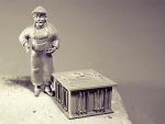
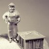
Unfinished from a previous post is a rain slicker that I wanted to hang on the pilothouse coat rack. I received some great suggestions from Druxey and Chris on possible approaches, but I just couldn’t get it right. I ended up using polymer and even though I’m not thrilled with it, I’m going to surrender and call it done. At just over ½” tall, this is the result.
The navigation lights are made of styrene and approximately 1/4" tall. I begin with the basic size and proportion requirements.
From this I select the four different shapes and sizes of styrene that will be needed – 2 tubes, a rod and some flat stock.
The rod and tubes that were selected are roughly the correct sizes and closely fit into one another. This defines the top of the housing.
A window is cut from the largest tube and the flat stock is used for banding.
The interiors are painted red and green and colored 0603 SMD LED's are soldered up and inserted. Clear Gallery Glass is used to hold them in place and simulate the lenses.
Directional light blocking boxes (I don’t know the proper term for these) are made up, painted and weathered. The NAV lights are glued in.
The searchlight is made up of styrene and brass. The bullet shaped housing is formed of .01" styrene. The tip of an ordinary construction nail was filed and polished to the desired shape. It was then heated and the styrene formed over it. A white 0603 SMD LED is inserted. It is painted with enamel and weathered with acrylic. A water based weathering is used so as not to effect the underlying enamel.
An air horn is made up which scales to about 18” in length. It too is made of styrene. The cone of the horn was made of a tube that was a larger diameter than required. The tube was heated in the middle and pulled to form the cone shape.
Painted
A pair of 1411 LEDS is placed up between the roof rafters for general interior illumination.
Everything glued onto the roof.
There will also be a pair of brackets attached to the roof for holding a dory. But I’m holding off on that until the dory is made.
Thanks for stopping by and taking a look.
Gary
-
kees de mol reacted to FriedClams in New England Stonington Dragger by FriedClams - FINISHED - 1:48 - POB
Thank you John, Keith, Druxey, G.L., Maury, Valeriy and johnp76 for your kind comments. I really appreciate it.
And thanks to all for stopping by and hitting the like button.
That's a good suggestion Druxey, I'm going to give it a try. Thanks.
Pilothouse Roof #1
One of the first decisions I made in modeling this boat was the time period in which it was built. I chose the 1920’s to early 1930's for a couple of reasons.
First, it was during this time period that these Western-rig boats were developed and came into wide spread use in southern New England. The inshore fishery was abundant and fish landings were strong. So there's an element of historical nostalgia to it.
Second, the era predates exterior plywood. Manufacturing of plywood as we know it today dates back to 1905, but waterproof adhesives wouldn’t be developed until 1934. So wooden boats were still being stick built with solid wood. And I prefer the detail and visual interest of individual boards to sheet goods.
Images of boats from the 1950’s and 60's show mostly pilothouses with simply constructed flat roofs. This is possible due to the extraordinary strength and durability of marine grade plywood combined with epoxy coatings. In contrast, the drawing below shows how earlier cabin roofs were constructed.
The curvature of the rafters gave the roof strength of the arch, water shedding and esthetics. Waterproofing was typically achieved through a covering of canvas/pitch or a rubber membrane. The 1 x 1 strips secured the edges of the covering.
I began by making the eleven arched rafters.
By creating a circle in CAD that describes the arch, I was able to bend material for all the rafters at one time. I cut the individual segments and positioned them on a template drawing. These rafters are placed on one foot centers which seems a bit of an overkill, but as a mechanical engineering friend of mine would say "when in doubt - make it stout.”
I then planked the top and added the fascia.
I’m going to simulate a rubber membrane roof covering. I did not sand or level the roof surface because I want the individual boards to show through the “rubber.” The surface was painted black and tissue paper will be used for the covering.
A thinned down PVA mixed with charcoal colored acrylic paint was liberally applied to the roof. The tissue paper (gift wrapping type) was applied to the wet roof and then more of the same PVA mix applied to the tissue. I jabbed at the tissue with a stiff paintbrush to create the wrinkling effect.
Edge trim was added and white pigment powder scrubbed in around the perimeter.
Roof scuppers were added to the aft corners.
Next post will be navigation and search lights. Thanks for stopping by.
Gary
-
kees de mol reacted to FriedClams in New England Stonington Dragger by FriedClams - FINISHED - 1:48 - POB
Pilothouse Interior #3
This update will complete the pilothouse interior.
There will be a separate switch somewhere on the display base to operate an interior cabin light, so I need to provide some interior details. The question for me is always - how much detail is enough? The level of detail found in the real world is simply way beyond my ability to recreate. So instead, I try to suggest detail and depend on the mind’s eye to fill in the rest.
I began with the door, which will be open.
I drew it up along with a bolt pattern for the strap hinges that would typically be attached to the rails on the reverse side of the door. The door swings inward and up against the wall so the hinges won't be visible and therefore have zero detail.
I first made up some hinges from styrene. They are scale 4” wide.
The door itself was made up from four strips of wood glued to three rails. It was then positioned on the backside of the drawing template so I could mark the hinge bolt locations.
Once the door was colored, I blackened the pinholes that simulate the hinge carriage bolt heads. This was done by poking a very fine dressmaker’s pin into the tip of permanent marker then placing it into the hole and giving it a little twist. A pinhead is used for the doorknob.
The hinges look too large to me. After the exterior siding and door trim are placed, I'll re-evaluate. If they still look too large I’ll try coloring them to contrast less with the jamb.
Under the window is a coat rack. I intend to hang a coat or rain slicker there, but simulating material with the correct texture and drape at this scale is a challenge and needs some rethinking. So for now, it remains empty.
I made a cabinet with a flat upper drawer for charts and what not.
I installed the cabinet and added a top and a few rolled up charts. Also shown here is a fold down seat for the skipper and a vertical grab iron between the windows.
This model will be displayed as a vessel under repair. And repair work requires repair parts, which often come in corrugated boxes. So I’m going to place a couple of them under the coat rack. I’ve played around with different ways to model small boxes before and always come back to the most simple - folded paper.
So I start with a drawing of an unfolded box complete with printing.
The most difficult part of this process is getting the color right. Using gauche in a very watery mix of yellow ochre, burnt sienna and grey produced an acceptable result. Any color medium that doesn’t bleed the lettering will work.
I then cut the "boxes" from the paper and folded them up. But simply folding and stacking them produced disappointing results. They looked like what they were - little pieces of folded paper pretending to be boxes. They need to look like they have weight. So I modeled the larger box to look as though it had been wet at one point and the smaller box was thrown on top.
The cut out in the floor provides access to the engine room, galley and berths. There is a ladder/stair that descends down, but only the top tread is visible from any cabin opening - so that is where the modeling stops.
That completes the interior and I’m glad to be getting out of such cramped quarters.
Thanks for taking a look.
Gary
-
kees de mol reacted to FriedClams in New England Stonington Dragger by FriedClams - FINISHED - 1:48 - POB
Thank you John and Keith. And thanks to everyone looking in and hitting the like button.
Pilothouse Interior #1
With the frame for the pilothouse done, it’s time for the interior wall covering.
But first I need to install the jambs on the six windows and the door. The jambs protrude from the frame both inside and out because they need to be flush with the outer surface of the wall covering. They are cut from 1/32” basswood sheet. This material is out of scale, but once the trim casings go on, only the face of the jambs will show with a reveal on the edges.
The openings of the frame were cleaned in the corners before the jambs went in to remove any adhesive squeeze out.
Next I added a band of wall frame cross supports that will serve as a landing spot for the lower edge of the exterior siding.
This is necessary because the pilothouse floor is lower than the forward deck as shown below.
The interior vertical wall boards are about 3.5” wide. I begin by staining a trial batch of wood. I stick the wood down to a sheet of paper using double-sided tape. Chalk is scraped off the side of sticks directly onto the wood and alcohol is used to liquefy and spread it. I want color variation so several chalks are unevenly applied in loosely defined mini piles. If the colors are evenly distributed it simply blends into a homogeneous color and that is not what I’m after here.
The color is darker when wet and certain colors will not fully emerge until it has completely dried.
I didn’t care for the reddish oxide tone of the trial batch, so I changed colors and found something closer to what I had in mind. In the end a scattered mix of burnt umber, raw umber and burnt sienna was used. The raw umber has a subtle green tint that I like. When it was dry, I went over the surface with fine sandpaper. To bring up a slight sheen, I lightly polished the wood with a little beeswax on the tip of my finger – more like burnishing really.
Then the floor of the cabin was constructed by gluing 6” wide floorboards directly to the template and cutting away the waste.
It was stained and a foot traffic pattern worn in. The floor is reinforced on the bottom side.
Next I made up the interior window casings. I first drew up the six window cutting templates. Only the fore and aft facing windows have square corners.
Then with the aid of double-sided tape, I cut and glued the casings together.
I painted the casings, window jambs and material for the shoe base an off-white acrylic. I then glued the vertical wall boards and all the trim into place.
Sitting on the floor section. The floor will not be glued on just yet.
Thanks for stopping by.
Gary
-
kees de mol reacted to FriedClams in New England Stonington Dragger by FriedClams - FINISHED - 1:48 - POB
Dave and Alexander - Thank you very much - I truly appreciate it.
And thanks to everyone hitting the like button.
Pilothouse Frame
Here’s a profile drawing of a typical pilothouse for this boat.
I used the above image and a similar one of another boat to produce the pilothouse drawings for this model.
The mast on this boat is perpendicular to the water line and the aft facing wall of the pilothouse is parallel to the mast. The roof and floor have a 4-degree pitch upward as it extends forward, so the sidewall framing forms a parallelogram rather than a rectangle. The small front angled walls are less steeply pitched because they point away from the sidewalls at 45 degrees. They have a pitch rise of only 2.9 degrees.
All six walls are drawn up.
Cutting templates and part locating drawings are printed for all walls.
Basswood is cut and assembled into wall sections.
Then the wall sections are combined.
Strip wood is cut and mitered for use as wall top plates. They extend a tad into the interior beyond the wall frame. This serves as a termination point for the vertical interior wall boards when they are placed and it also provides a wider landing spot for the roof beams.
Holes are drilled through the framing to hide the wiring for the P/S running lights, interior lighting and a pair of exterior rear facing floodlights. Notice in the photo below that the middle cross support in the angled wall has been replaced with two parallel facing boards. The windows slide down into pockets and this one window will be shown partially open.
When the forward deck was installed, the opening for the pilothouse was purposely left too small. With the frame completed, I now filed the opening to fit. Then the frame was placed just to see how it looked so far. The pilothouse will be detailed and totally completed before it is glued into place.
Thanks for taking a look.
Gary
-
kees de mol reacted to FriedClams in New England Stonington Dragger by FriedClams - FINISHED - 1:48 - POB
This post is unrelated to my Stonington dragger build and is just something I wanted to share. I hope this isn’t bending forum rules too far.
I’m in the process of building a series of small shadow box dioramas in 1:87 scale. Each diorama is 2.25” x 4.75” with a maximum depth of 2.5”. The exterior dimensions of the shadow box is 8” x 5.25” x 3” deep. It is made from poplar and assembled with biscuits. This is the second diorama I’ve completed and depicts the interior of a small fictitious boat building shop. It is completely scratch built with the exception of the following items:
The brick wall material is from New England Brownstone Co. in Massachusetts. It is made in white Hyrocal slabs that you cut and color as needed.
The window frames, truss rod queen posts, turnbuckles and the 55 gallon drum are unpainted injection molded styrene from Tichy Train Group in North Carolina.
And the two human figures are from Preiser in Germany.
I apologize for the quality of these images as they were shot through the glass using a polarizer and only diorama LEDs for lighting.
The exterior photographs visible through the windows were scaled and affixed to the inside of a PVC pipe that was split lengthwise creating a concave image plane. This means there is no upper or lower edge of the photo that can be observed. And because the photo sits back away from the window, the image shifts as the observer moves and their visual perspective changes.
I installed two pushbuttons into the bottom of the case that control interior and “exterior” LED lighting. Being able to control them separately allows for day/night display scenarios and changes the mood - much more than I expected. Compare the “nighttime” shot below to the “daytime” (with interior lights on) shot above.
And then exterior lights only.
Interior lights only.
Exterior lights only.
And a couple of other shots.
Thanks for taking a look – now back to the fishing dragger.
Gary
-
kees de mol reacted to FriedClams in New England Stonington Dragger by FriedClams - FINISHED - 1:48 - POB
Keith, John, Druxey, Mark and Alexander - That you for your kind words and for looking in on my build. I appreciate it.
Dave B - Glad that you find my log of interest, and thanks for the compliments. Happy to have you following along.
And thanks to everyone looking in and hitting the like button.
Some Deck Details
This is a small update showing the addition of a couple of minor deck details:
- Trim around the base of the fish and ice hatches
- Two fish hold deck plates
- Added rail to the port side
The added rail shown prominently in the following 2 photos is a mystery to me. I don’t know what it’s called or what its purpose is. It is shown in nearly every photo of every Stonington style dragger I have seen. It is always on the port side directly in front of the sorting pens.
- Is it to keep fisherman from flipping backwards over the rail when sorting fish on a slimy deck? It doesn’t seem high enough to prevent that.
- Or does some kind of cleaning table set on or hook over it? I have not seen a single image that would even suggest this.
If someone knows or has a theory – I’d love to hear it.
Here are a few more photos.
In this final photo a faint deck wear pattern is beginning to emerge. I don’t want to commit until the winch and gallous frame are built and placed.
Next I'll be starting in on the pilothouse.
Thanks for stopping by.
Gary
-
kees de mol reacted to FriedClams in New England Stonington Dragger by FriedClams - FINISHED - 1:48 - POB
Chris, Druxey, Michael and Dan - Thank you for looking in on my build log and for your kind words and encouragement. I sincerely appreciate it.
And thanks to all who stopped by and hitting the like button
Here’s an overview of hatch positioning on the aft section of the deck.
The placement of the bitts and the curvature of the transom differ here from my model because it’s a different boat. I’m choosing this deck layout simply because I found it in drawings and photos more often than any other layout.
The area highlighted in green is the top of the storage and sits 15” above the deck surface. There are two removable covers, one on each side.
The orange lines represent the wooden planks that make up the fish sorting pens. Period drawings often label this area “checkers.” These pens can be assembled in different configurations and pulled apart to be set out of the way. Even though the drawing indicates that these pens can be set up on both starboard and port side, I have not seen a single photo showing this in practice on these small draggers. They are always on the port side only. In use, the trawl net is emptied into this area and the catch is sorted by size and species. Non-target fish that still have a market value are sorted out into separate pens and boxes.
The image below shows a mixed catch of lobster and fish in the sorting pens. The photo is from an excellent book by Peter K. Prybot titled White-Tipped Orange Masts.
To get started on the storage area, I install a couple of support beams for the decking. They have been bent to match the crown of the deck and installed so the top sheds water forward.
A card template is made for the forward facing side. Wood is glued to it, cut out and then stained.
Card is cut and glued to the top of the storage area. Leaving the ends wild, pre-stained boards are glued on. The boards scale to 1” x 4”. Once this was complete, I tore them all off for a re-do, because they were crooked and looked terrible. In this photo you can see the boards tending toward port. After all boards were on, it was much more obvious.
After the redo, I filed the board ends even. And though the boards now appear to be pointed slightly starboard, I have convinced myself that it’s just a camera angle illusion thing. Before I am done with this storage deck, it will receive a wash to tone down the contrast a bit.
Next, I layout the cover positions and cut a hole in the deck for the hatch cover frame. Although there are two covers, only one will be removable on the model. The frame and the two covers are made.
Cover handles are bent from .0125 phosphor bronze wire and placed. I’m using the bronze wire over brass simply because that’s what I have. But as a side note, most of the fine wire I use in modeling is phosphor bronze. Like brass it’s a copper alloy, but it is harder and has more spring to it. It doesn’t have a tendency to slump like brass wire does, which makes it ideal for railings, tie rods, guy wires, etc.
The handle escutcheons are 1:160 styrene eyes.
Next, the pen boards are made up.
The sequence is simple and produces predictable results. In these next photos, I setup the lighting for strong contrast to show grain in the wood - so the texture appears exaggerated.
The piece of basswood is 3/16” x 1 ½”.
First, it is wire brushed to bring up the grain (soft wire brush).
Then hand holds are cut with needle files.
A hole is drilled to accept a knot. It is placed where the wire brush found softer material and dug deeper. This deeper cut is exaggerated with a file leading into the knot hole.
A toothpick is glued into the hole and cut flush on both sides. The wood is stained front and back with chalk/alcohol. The white along the bottom is meant to represent salt wicking. To get the colors to blend on such a small piece, a lot of alcohol was used. There is no such thing as too much alcohol – I’m talking about modeling here remember.
Wood 2" x 2" are installed as placement guides on the hatch sides and stanchions. The board ends slide down into these guides. Styrene nut/washers are added to the guides.
The arrangement of pens is slightly different on my model than is shown on the layout at the beginning of this post. The drawing depicts a larger boat and has pens forward of the fish hold. Smaller boats like mine have the hoisting winch directly in front of the fish hold and deck space is at a premium. These small boats sometimes have a diagonal pen off the port side of the fish hold. So that is how I configured mine.
Notice that of the three large pens, only the forward two have pen boards up against the bulwark stanchions. This is to keep small catch from slipping out through the scuppers.
Thanks for taking a look.
Gary
-
kees de mol reacted to FriedClams in New England Stonington Dragger by FriedClams - FINISHED - 1:48 - POB
Thank you John - I appreciate it. And thanks to those looking in and hitting the like button.
Fish and Ice Hold Hatches
I intended to include the equipment storage and checkers in this post, but that will be the next one.
The fish hold hatch sits slightly forward of center on the aft deck. It measures 8 feet long by 4 feet wide and has three covers. The hatch coamings are 11” high, but I’m building the box out of slightly wider material. This will allow me to profile the bottom edges to conform to the crown and sheer of the deck without loosing the 11 inches in height. The ice hold sits aft of the fish hatch and is 4.5 feet x 2.5 and stands 8” high.
I begin by drawing up the hatch coamings and covers for both fish and ice holds.
From 1/16” thick stock, I cut the coamings needed for both hatches.
I use a 1-2-3 block as an aid in producing a square corner. CA is being used because I’ll be using alcohol to color them. And as you know, PVA and alcohol don’t play well together.
I use a flat sanding surface to maintain flat square surfaces all around. I find it easier to push pieces around on a stationary flat surface than to sand a stationary piece with a moving sanding surface. I’ve made several of these surfaces - different grits of paper and emery that are glued down to both sides of a 4” x 7” piece of craft plywood. Having grit on both sides keeps them from sliding around.
Before I begin the hatch covers, I confirm the frame size.
To make the covers, appropriate sized strips of wood are glued directly to the drawing extending across all three covers.
I then cut along the dashed location lines with a straight edge and blade. They are left wide and will be adjusted later.
Coloring the frames starts with applying a mixture of India ink and 70% ethyl alcohol. (Any alcohol works.)
Then the frames are painted with an off-white acrylic and allowed to dry for about ten minutes. Applying regular cellophane tape to selected areas of the paint and then tearing it off like an old bandage leaves a peeled paint appearance. More paint can be pulled off in areas where you burnish through the tape surface. There is a window of time when this technique works most effectively – letting the paint dry too long or too little produces disappointing results. Experimentation on scrap is essential. Different species of wood and stain/paint combinations work with varying degrees of success. But it always works. (Batteries not included and your mileage may vary.)
The hatch covers are stained next. They are placed on a sheet of paper with double-sided tape. Chalk is scrapped off the side of soft pastel sticks (dry, not oil based) into three small piles – black, brown and white. After applying a wash of ink/alcohol, I highlight areas with the chalk. Black and brown for general coloration, and white to simulate sun and water bleaching. The chalk is applied with a brush wet with straight alcohol. Touching the chalk dust with the brush produces a puddle of wash as subtle or bold as you wish depending on the amount of alcohol applied. It penetrates the wood and can be blended and re-worked with straight clean alcohol. White is the most difficult to work because you can’t see it while wet. You have to wait for the alcohol to evaporate off to see the results.
Where too much chalk was applied, I remove and/or blend it back with clean alcohol.
This photo shows the three-stage progression.
For lifting rings I found some guy wire eyes in my styrene junk yard that scale to 3” in diameter. They were painted flat black enamel and glued into indents in the hatch covers. Brown chalk was used to simulate traces of rust on and around the pulls. This helped in visually setting the pulls into place.
Finally an insert is placed into the frame to hold the covers.
The ice hatch was built in the same way.
I’m going to hold off placing these hatches on the deck for now, as they would interfere with upcoming work.
Next - equipment storage and checkers.
Thanks for taking a look.
Gary
-
kees de mol reacted to FriedClams in New England Stonington Dragger by FriedClams - FINISHED - 1:48 - POB
Keith and John - Thank you for your comments and interest in my build. And thanks to all who have stopped by and for hitting the like button.
Railcaps
Here is a short update showing the rail cap and stern area bitts installed.
To begin I needed a pattern for the rails.
I took a sheet of letter-sized paper and placed it on the deck/bulwarks of the model. Running my finger over the paper and along the edge of the boat left a nice clearly defined crease in the paper. I did this for both P/S rails. Care was needed to keep from shifting the paper while tracing the edges. I found this much easier than tracing with a pencil.
Using a French curve, I refined both creases into smooth arcs. I then cut along these lines and held them to the model to check for accuracy. Satisfied, I then transfer the arcs to cardboard and cut them out. These were then glued to a cardboard base. This would serve as my forms for the railcaps.
To make up the caps, I laminated two strips of basswood with PVA and pinned them to forms to dry. Waxed paper was put down to keep them from sticking to the cardboard.
Once dry, they were sanded flat and smooth then trimmed and fitted. They were attached to the model using CA.
Extra material was added for a wider rail at the aft deck. Inwales were installed and rail cap was added across the top of the transom. All were base painted white.
Bitts were made up and installed through the railcap in each corner of the stern. This turned out to be one of those tasks that you think will be simple and fast, but ends up taking a lot longer. The bitts took no time to make – a square piece of wood cut to length with a piece of blackened brass stuck through it. But cutting the square holes through the railcap took much longer. They have to be positioned the same on each side. They have to stand parallel with the deck boards rather than the railcap. And one errant stroke of the file and the hole would be out of square, crooked or worst of all - too big.
Some other views.
Next, I begin on the equipment storage area, ice and fish hold hatches and the checkers.
Thanks for taking a look.
Gary
-
kees de mol reacted to FriedClams in New England Stonington Dragger by FriedClams - FINISHED - 1:48 - POB
Thank you Druxey and Keith for your words of encouragement. And thanks to everyone for looking in and hitting the like button.
Decking
To begin, I make up the deck beams by cutting 1/8” square basswood stock into approximately 4” lengths. Each beam is allowed to soak in ethyl alcohol for about 15 minutes before bending them to match the arc of the CAD printout. For gentle sweeping bends like this, I prefer alcohol simply because it dries so quickly.
Only 9 beams total are needed. As soon as the beams are dry, they are cut and sanded to fit, then glued into place. The beams are installed beginning at the point where the hull is the widest and then installed toward the bow and stern. If a beam is inadvertently cut too short, it could still used at the adjacent narrower hull position.
Additional stanchions are needed beyond those that are provided by the hull bulkheads; so intermediate stanchions are placed at the aft deck. Acrylic gray is applied to the stanchions and bulwark as a base color. Next, the covering boards are notched around the stanchions and checked for fit – then adjusted and re-checked over and over and … Finally, they are painted off-white acrylic as a base and glued into place.
Before the decking can begin, a socket for the mast is made up and installed. A short mast placeholder is inserted.
The deck planking used on this model scales to about 3.5” wide by 2” thick, which is in line with what I found to be typical for this boat.
The deck boards are placed on a piece of waxed paper and pre-stained with a mixture of India ink and alcohol. They are stained unevenly so the decking has a wide range of light to dark coloration. This is a base only and is applied to accentuate the wood grain and provide depth and visual separation between individual planks. When the decking is complete, it will be sanded and color washed.
At the beginning of every modeling project a decision about level of detail must be made. This is often driven by scale. The deck planks are .072” wide and a total of 62 planks make contact with the covering boards, so I decided not to nib them in. This model is not being built to celebrate its beauty - it is a working boat built to depict gritty reality. Or at least that is the goal. If this sounds suspiciously like a justification of laziness posing as a reasonable explanation – you might be right.
The king plank is the first to go on and then the planking proceeds to the covering boards.
With the aft deck completely planked, it looks like this.
After the deck is sanded, a wash of gray gouache is applied. It is thinned down considerably with water. Unlike watercolor, gouache is opaque but can be made translucent. It is also very flat, even dusty looking when applied in this way. And it is very forgiving and can be re-worked.
Here is a before and after of the same section of deck.
There will be more work done to the deck surface once equipment and hatches are installed and wear patterns established.
It’s hard not to look at the top of the stanchions and bulwark, but the weathering and wear to the covering board is the purpose of this photo. The acrylic paint was picked at with a dental tool and ink/alcohol applied. The alcohol bubbled up the paint and the ink stained the wood beneath. Loose paint is then scraped off.
Next, an area for the pilothouse is framed in the forward deck.
The planking and coloring is applied same as the aft deck.
Thanks for taking a look.
Gary
-
kees de mol reacted to FriedClams in New England Stonington Dragger by FriedClams - FINISHED - 1:48 - POB
Thanks to all for the hitting the like button - I appreciate it.
Keel Correction
Whether it’s a scale model or a bathroom re-model, I expect to encounter problems in just about everything I do. For me, finding solutions to the unexpected is part of the fun of model building. But it’s not fun when I cause the problem.
There should be a minimum of 6 inches of keel showing below the hull planking – there is only 2. So I added on 5 scale inches to the keel. I also added one scale inch to the stem. This brought the keel back to the proper exposure.
Some sanding and some paint will cover the patched-on wood.
Here is a before and after:
In the next photo, notice how the lowest hull plank swings upward away from the keel as it approaches the sternpost. It should remain parallel with the keel. Sometimes my desire to push ahead causes me to lose focus on the task at hand. I should have either tapered those lowest planks wider as they ran toward the stern or added steelers.
Rather than pull the lower 5 planks off each side for a re-do, I opted instead to mitigate the error with a cosmetic alteration. Also, I sanded down the planks that are lying flat against the sternpost to a thinner profile so that they appear rabbeted in with a slight reveal.
Thanks, Gary
-
kees de mol reacted to FriedClams in New England Stonington Dragger by FriedClams - FINISHED - 1:48 - POB
Transom
Here are a couple of photos of the transom backing taken after the hull was cut away from the base and before the top three courses of hull planking were put on. The tab that secured it to the building base hasn’t been removed yet. You can see the temporary jig holding the transom backing to the required curvature. Now with the hull planking on but still running past the transom, I am able to remove the temporary jig and apply the three transom boards that will make up the outer surface of the transom.
First I cut the boards from the basswood sheet leaving extra material to sand and fit each board. Unlike the transom backing where the wood grain is vertical, these boards are cut so the grain is horizontal.
Test fitting these outer boards was rather tedious and fiddly because I couldn’t cut the hull planking flush until the outer transom boards were on. They also had to be pre-bent against the grain to fit the curvature of the transom backing. One at a time they were fitted, held in position with clamps and glued with very thin CA. A few drops of the CA applied to the upper edge of each board were all that was needed to secure them. The watery CA raced down between the two wood surfaces, effectively creating a two-layer plywood.
At this point the base tab was removed and the hull planking trimmed and sanded flush.
Marking the water line was simple by placing the model back onto the base. The irregularity of the cuts when the boat was separated from the base allowed it to key back into place exactly and perfectly level.
There are several problems with the keel, stem and area around the sternpost that need to be corrected. They will be addressed on the next post.
Thanks for looking in.
Gary
-
kees de mol reacted to FriedClams in New England Stonington Dragger by FriedClams - FINISHED - 1:48 - POB
Thanks Keith
Lining OFF
Beginning the sawdust phase, I cut the bulkheads out with my scroll saw leaving the piece large (cutting to the outside of the template line.) I do this because I have no skill with the saw and cannot keep to a line. I then use a bench top disc sander and work back to the template outline. This works great with the convex edge and I use a Dremel sanding drum for the inside curves.
I glue these forms to the platform base and attach the keel/stem. Before the keel went on, I cut a rabbet on the stem.
Using a batten to see how the bulkheads faired, I found a problem. Station #8 was too small and #7 was ridiculously too large. Looking back at the body plan it’s hard to see how I missed it. But, that’s the point of going through the fairing up process. So, I built up #8 and went after #7 with a file.
Based on photos and drawings, the planking widths for this vessel seem to vary in the 5” to 7” range. I have a stash of stripwood that scales to approximately 6.5” wide x 1.75” thick so decided to use those. Because station #7 has the longest edge length of any bulkhead, it will be the location where the planks are at there full width. From here they taper to the stem and taper back to the stern. It will require 23 courses of planks per side.
There will be 4 belts per side of 6 planks each. Belt #1 beginning at the keel will have only 5. From station #7 back to the stern, 4 planks are lost in belt #1.
I measure the length of each station edge and check it against what my CAD drawing says it should be. Knowing how many planks will be required, I generate the following plank width tick mark strips for each bulkhead edge.
The width of the planks at the bow is just under 5.25” which satisfies the “not less than half” plank width guideline. No steelers or drops are needed.
The strip marks are temporarily taped on the bulkheads and a batten strip is used to get a general sense of the curve following the tick marks.
Happy with the way it looked, I transferred the tick marks to the stations with pencil and temporarily attached thread at each belt as a final check to see how the plank courses run. After a few minor modifications, I was ready to start planking.
Planking
The coloring and weathering the model will receive will not only reveal but also accentuate the planking on the hull, so I won’t be using any filler or putty. On a previous model, I planked the hull somewhat haphazardly, knowing that I was going to slather Bondo on it and sand it smooth. I’m happy with the way the model came out, but it would have been more realistic with the planks showing through the paint.
I set up a little jig to hold the stripwood firmly in place as I slice the taper into it - then sand to fit
I begin planking at the keel with the garboard and lay on two belts of planks on one side. Each course is tapered on the upper edge of the planks so that each successive course starts with a straight edge.
Each course of planks is made from a single strip of wood. After it is tapered and test fit, it is then cut to simulate the butt ends of two individual boards. The joints are reinforced on the reverse side.
Two more belts are added to the other side.
Then the last 4 belts are added minus the top three courses.
At this point, I cut the hull from the platform.
The next course of planking requires the scuppers.
Finally, I sand the hull and finish it off with a soft brass wire brush. The wire brush removes the sanding shine and any cross grain scratches and in general sort of unifies the look. It will also help with the weathering later on.
These final photos were taken in full direct sunlight in hopes that the effect of the wire brush can be seen. A few final licks with 800 grit paper will take the remaining wood fuzz off.
This post brings me up to date in real time on this model.
Thanks for taking a look.
Gary
-
kees de mol reacted to FriedClams in New England Stonington Dragger by FriedClams - FINISHED - 1:48 - POB
Hello Michael and John. Glad to have you looking in.
Some CAD Work
The hull dimensions come from an article by Charles S. Fox published in Ships in Scale magazine (Volume XII, No.1. 2001.) The article and plans are cursory and give little in the way of details, but is a good place to begin. The boat is 45’ in length, which equals 11.25” in 1:48
This build begins as most POB models do with developing bulkhead stations. So first I photograph the plans, straighten, clean and brighten them in a photo editor and then import into CAD. After more adjustments, I scale the images and trace the body plan onto a separate layer. I then make corrections, apply some line smoothing and mirror the bulkhead halves.
This model is being built upside down, so each bulkhead will have a tab included to reach the platform base. The length of the tab will of course be different for each station.
In profile it looks like this. As per the drawing, each station is 5’ apart.
The body plan lines are to the top of rail, but I’m redefining that point as the top of stanchions. The aft deck is 18” lower than that point, so those bulkhead templates are modified to reflect that. So for example, #7 station ends up looking like this.
Finally, I need a way to cut the completed planked hull away from the base. A horizontal cut through each bulkhead that can be reached with a Dremel cut off saw will do the trick.
The keel and stem are taken from the drawing and traced. It is cut into two pieces and arranged to take advantage of grain strength, then rejoined and installed as a single unit. Later in the build it will be incised to imitate/suggest actual joinery.
The bulkhead and keel templates are printed onto full sheet labels (blank 8.5 x 11 copy paper with an adhesive reverse side and peel off backing.) The bulkheads are cut from 3 mm craft plywood. The templates are arranged so the straight mounting edge lies along the factory edge of the 3 mm plywood. The transom (station #9) is cut from 1/16” basswood sheet. This is necessary because the transom has a gentle convex arc and the plywood is too stiff. The transom will be held in that shape with a temporary form and will eventually have an outer plank layer. The keel/stem is cut from 1/8” basswood.
The next post will be the lining off and a compression (not a skip over) of the complete hull planking which will bring this log up to where I am today in real time.
Thanks for taking a look.
Gary
-
kees de mol reacted to FriedClams in New England Stonington Dragger by FriedClams - FINISHED - 1:48 - POB
A “dragger” is a fishing vessel that tows a trawl net. A trawl can be dragged along the bottom of the seafloor, just above the bottom, or in midwater depending on the target species.
In the early 1920’s the Connecticut fishing industry began producing what is known today as the Western-rig dragger. These boats were not the first pilothouse forward fishing boats built in New England, but due to their small size, the design was affordable and perfectly suited to independent fisherman working the local inshore waters.
These small fishing draggers were typically less than 60 feet in length. Built of steam bent oak frames and planked with yellow pine or white oak, they were both light and strong. The popularity of this Western-rig design quickly spread and by the 1930’s could be found in many ports of southern New England. The use of these boats for ground fishing was so prevalent in the port of Stonington, Connecticut, that the design commonly became known as “Stonington Draggers.”
Western-Rig - Winthrop Warner Collection, Mystic Seaport Museum
Western-Rig vs. Eastern-Rig
The difference between a Western-rig and Eastern-rig boat is one of deck arrangement and not the gear used in catching fish. Western-rig boats have the pilothouse positioned in the bow with the working deck aft. On Eastern-rig boats the working deck is positioned mid-ship with the pilothouse in the stern.
Eastern-Rig - Albert E. Condon Collection, Mystic Seaport Museum
The Eastern-rig deck arrangement evolved from the New England fishing schooners and “auxiliary schooners” which required the helm to be over or near the rudder. But once fishing vessels became fully powered with a tiller system and rudder quadrant installed, the pilothouse could be positioned anywhere. Enter the Western-rig.
Western-Rig - Winthrop Warner Collection, Mystic Seaport Museum
The Western-rig has some advantages. With the pilothouse forward in the bow, there is easier access to the fo’c’sle and the engine room. It also provides better visibility for the captain, and the crew is somewhat safer in bad weather working behind the pilothouse rather than in front of it. One disadvantage to having the pilothouse in the bow is that the windows are more vulnerable to being smashed out in bad weather.
In the early days, the Western-rig boats were small and only used for inshore fishing while the larger more powerful Eastern-rig boats fished offshore. In time however, the Western-rig boats grew in size and power to become today’s offshore stern trawlers and the dominant fishing vessel type.
The Otter Trawl
Even though the Western-rig Stonington boats had an open aft deck and a square stern, most continued to drag off the side. And like the Eastern-rig boats, the gear most commonly used was the “Otter Trawl.”
Otter trawling was invented in England and came to America around 1910 – give or take. It derived its name from the “otter board” which was the name given to a sheering device that was being used for “hook and line” lake fishing in Ireland. Like a modern day planer board, this rectangular wood board would sheer on the water surface and course away from the direction it was being pulled. In commercial fishing, the otter boards are industrial scale and can weigh hundreds of pounds. Two such boards (commonly called doors) are used to hold open the mouth of the trawl net. Like underwater kites, the otter boards are setup to push outward, away from each other, as the hydrodynamic pressure of moving water acts upon them. This was a major advancement over the “beam” trawl, which as the name implies requires a beam of some sort to keep the mouth of the net spread open. Needing a beam also severely limited the size of the trawl being towed and was cumbersome and impractical for a smaller boat. Now with the otter trawl, a single small boat, like the Stonington dragger, could tow a net limited only by its engine power.
The Otter Trawl - above & below Copyright Seafish
The drawings, inspiration and photos for this build come from several sources and the model built from them will be a vessel typical of the design but not of a single example. The hull will be built from one source, while some detailing and features may come from elsewhere. All features and details will depict what would have been found on actual boats – nothing will be added for the sake of visual interest.
This model will be weathered to show honest wear. It will not be a wreck, but I have never seen a pristine commercial fishing vessel. Hard working fisherman worked these boats hard. I hope to capture that feel without making a caricature out of it.
Thanks for taking a look.
Gary
-
kees de mol reacted to Javier Baron in Zulu by Javier Baron - FINISHED - Scottish herring lugger
Thank you very much for commenting. the zulu is already finished, just in the absence of the showcase manufacturing.
Javier
-
kees de mol reacted to Javier Baron in Zulu by Javier Baron - FINISHED - Scottish herring lugger
To make the sails, I first cut out a pattern on paper and check on the model that its size and shape are correct.
As in this case the sails are colored, I have chosen brown fabrics to which I have given a reddish gouache. The fabrics are cocktail napkins that come in a roll from which they are detached, and although they are disposable, they can be used several times, as they can be washed. In the end I opt for the darker one.
Putting the napkin on the bias (that is, diagonally) I have been cutting strips of 3 mm. wide. Then I have glued these strips, one with the other, with minimal overlapping, making a composite canvas, from which I have then trimmed the sails using the paper patterns.
The edges of the sails are very thin strips of cloth that stick over the sails. These very thin strips are trimmed from the edges of the napkin, as they are treated with a varnish or resin sizing that prevents fraying.
-
kees de mol reacted to Mirabell61 in Zulu by Javier Baron - FINISHED - Scottish herring lugger
excellent build Javier !!
I love these small workboats
Nils
-
kees de mol reacted to Javier Baron in Zulu by Javier Baron - FINISHED - Scottish herring lugger
Thank you for your comments.
I have already painted the hull
-
kees de mol reacted to Javier Baron in Zulu by Javier Baron - FINISHED - Scottish herring lugger
Continue...
-
-
-
kees de mol reacted to Javier Baron in Zulu by Javier Baron - FINISHED - Scottish herring lugger
Thank you very much to all for your comments.
I continue with the constrction of the model.
-
kees de mol reacted to Javier Baron in Zulu by Javier Baron - FINISHED - Scottish herring lugger
My current project is a lugger of the east coast of Scotland, a type of ship called Zulu, which was the most powerful and efficient sailboat for the herring sail fishery among those of its size in the British Isles.
Its origin dates back to 1879, the year in which a Lossiemouth fisherman, William "Dad" Campbell, devised a radical design for his new boat for the capture of herring. He had the vertical bow of the fifie and the sloping stern of the skafie, and called this ship "Nonesuch." It was relatively small, with 16 m. of length and a keel length of 12 meters.
This design, which provided a longer deck and a shorter keel, markedly improved the maneuverability of the boat and provided it with a good speed, characteristics that made it highly appreciated by herring fishing fleets, as they managed to reach promptly to the fishing grounds and return quickly with the catch. Due to these qualities, that type of vessel quickly became very popular throughout the Scottish east coast.
The new type of vessel was baptized as a Zulu because of the war that was developing in South Africa at that time, in which Scottish soldiers fought, a war that was rejected by the population who thought they were fighting in an English conflict that, deep down, they were not concerned, which made their sympathies lean towards the Zulus.
The Zulu ships were carvel built, instead of clinker built, which was the most common in those waters. They were provided with two masts carrying lug sails and a bow jib. The sails were heavy and difficult to maneuver, and the masts to carry them had to be very long and strong. In the Zulu of greater size, the masts came to be 18 m high in boats of 24 m in length. As the twentieth century approached, steam winches were introduced aboard, which made maneuvering sails and nets much easier for crews.
However, and despite the success of its design, the life of the Zulu was quite short, since it was replaced by steam fisherboats after a brief existence of just over three decades.