
Supplies of the Ship Modeler's Handbook are running out. Get your copy NOW before they are gone! Click on photo to order.
×

kees de mol
-
Posts
796 -
Joined
-
Last visited
Reputation Activity
-

 kees de mol reacted to Mark Pearse in 28' Ranger-type Yacht by Mark Pearse - FINISHED - 1:12
the rudder gudgeon & pintle are now fitted & the rudder is painted, the fitting looks to be in scale
The rudder curves are nice, unfortunately a phone camera lens seems to distort the shape of the hull - but you get the idea
The next metalwork part is the boom gooseneck. I bent a piece of brass flat bar (about 1.25mm x 4mm) around some wood of the right diameter, cut & brazed it. This is the band that will go around the mast. You can see that it's not exactly round, but I don't think that will show when you can't see the hole, when it's on the mast.
like this
Flange, grooved one side to help hold the next part, the tube
weighted to hold it during brazing, the tube didn't initially want to take the solder...
& the result: the next part is the pin, then the part that fits on to the forward end of the boom
until next time,
MP
-
kees de mol reacted to Mark Pearse in 28' Ranger-type Yacht by Mark Pearse - FINISHED - 1:12
The sponson have been glued on, plus the transom fashion piece that completes the timberwork of the sponsons around the stern. The hatches also located, there's some more deck timberwork - some spray rails, toe rails etc,
Looking like a boat now.
thanks, Mark
-
kees de mol reacted to Mark Pearse in 28' Ranger-type Yacht by Mark Pearse - FINISHED - 1:12
Back to the work bench again, lots of boating fun over summer...
I've started the rudder blade, as below. My understanding is that the designer put a sloping transom on this boat because he didn't like the fine edge of the rudder blade getting damaged by a dinghy, so the concave part of the curve near to the waterline might be altered to fulfil this intention.
The careful work of setting out the sponsons is underway; it's possibly the most challenging visual thing to get right on the design; the gunwales line give one curve, & the sponson line is in balance with that. The setout was done by wrapping the hull in about 6 large rubber bands & sliding the sponson strips underneath the bands. When I was happy I put a pencil line on the hull topsides. To help with accurate installation, I made some small studs that temporarily sat in drilled holes in the back of the sponsor strips. The positions were marked by pressing against the hull; the studs were replaced with brass rod that will help hold the strips in a stable position while the glue goes off.
studs
drilled holes in hull, repainting underway
sponsons with rods; also the 'teak' colour of the hatches went ok
-
kees de mol reacted to Mark Pearse in 28' Ranger-type Yacht by Mark Pearse - FINISHED - 1:12
Most of the finished raised deck cockpit parts have been installed. I'm happy with the shellac finish on the timber, about 8 coats well sanded, the final one with steel wool; & finally a thin coat of clear polyurethane finish was wiped on with a cloth to give satin finish, slightly glossy.
The deck in the cockpit area has been painted with the final colour, a matt cream colour. The edge of the seating footwell will be trimmed in timber, where the colour changes from cream to white.
The side rectangular panels are removable in the design, hence their beaded edging. The storm boards are simple, true to the intention that the boat was used mainly for the harbour & some short coastal trips. I've left the top part over-height to be trimmed down later. The 2 main deck hatches are started, I'll stain the timber a colour to replicate teak. The hatch details will be simple, a lot of boats here of that time had fairly poor hatches - I suppose that if it doesn't get too cold then it doesn't matter so much if it leaks air.
The capping pieces are not glued on yet, I may wait until after the topsides are repainted first, to be decided.
thanks
-
kees de mol reacted to Mark Pearse in 28' Ranger-type Yacht by Mark Pearse - FINISHED - 1:12
I reshaped the profile of the keel line to a smooth curve - it is probably not what would have been built, but it looks nice & does reflect the drawings.
The painting has been redone, & is probably not over yet; I'm sure there will be some damage, & the topsides might be too cream but it's hard to tell at the moment. The paints are all mixed, gloss enamel for the topsides & matt acrylic for the underwater parts. The boot top is a mixture of an opaque enamel with some metallic added, the colour will make sense when the gunwales & sponsons (lower gunwales) are added. The antifouling colour in enamel wasn't working out well, it wasn't matt enough & the colour was blue rather than pale grey. When the hull shape on a boat doesn't change shape dramatically near the waterline, I like an underwater colour that isn't a huge contrast to the topsides, so that you can see the shape into the water as an extension of the above-water shape, hence the pale grey.
The boot top line masking bled a bit, & the transom part seems to be off a bit, so some touching up required. Also, it might not be obvious in the photos but the line itself is not as good as I'd hoped, but when you realise that it's actually only a very small deviation from a the curve, it might not be practical to amend it by such a small amount as the change might not look so good.
As you can see, the right-way-up support frame is made & she was cut off the build frame - it's very nice to see the lines - it is hard to appreciate the lines upside down, we are probably so used to seeing them one way.
The next steps, I think, will be to cut the profiles as the hull steps down from the raised deck. Also deck beams & mock up the deck & cockpit area in 2mm plywood. At the bottom is the start of a deck plan, at the moment it just shows the basic shapes that would be in ply - the cockpit seating & edge of the raised deck etc. The cockpit seats are solid, not hollow under. I will shape it all in ply & add timber & veneer sheets as required. I have some Queensland Maple veneer & some timber as well.
Thanks for looking, MP
-
kees de mol reacted to Mark Pearse in 28' Ranger-type Yacht by Mark Pearse - FINISHED - 1:12
A minor update: some more painting with colours closer to what I had in mind: cream topsides with a white / pale grey antifouling. The boot top line hasn't been done but I have some coppery colours for that. White antifouling isn't true to the period of the boat, but neither will the winches be that I am going to indicate. I just like the effect of the antifouling being a similar colour to the topsides, you can see the continuity of the hull shape more clearly as it goes down into the water, or when a boat is heeled.
The issues with paint drying I think were to do with not stirring the paint enough before I decanted it into another jar - which I did to make a mix of colours. Thanks to those in the painting forum that helped out. You can see below that the matt paint that I've used for the antifouling is more uneven in finish than the gloss. If it's still uneven after another I'll investigate spraying the matt paint, blotchiness in finish will make a smooth shape look uneven
I will probably do one more coat to each before removing the model from the base. Some very fine splits between planks are showing through the paint, as joints with insufficient glue are moving. It's not so different to a real planked hull, so the sort of 'defect' that is true to a real boat of this sort of construction standard is being accepted.
Anyway, here they are:
the model with the original designer's half model of Ranger, the half model must be getting close to 100 years old now
again, showing the half model off
the half model, the 28 footer, plus Ranger herself through the window
Thanks all, MP
-
kees de mol reacted to Mark Pearse in 28' Ranger-type Yacht by Mark Pearse - FINISHED - 1:12
I've undercoated the hull & set up the boot top line, using a laser level to get the waterline & then adjusting the model height & angle to get the boot top lines. I marked the waterline in 6H pencil, added 50mm (scale) height slightly aft of the middle for the lowest point of the boot top line, which is increased to 100mm at the bow & 65mm at the stern. The boot top line width is 30mm scale width at its narrowest, 50 at the bow & 40 at the stern.
I like the way lines added on to a hull shape improve its appearance - or maybe its truer to say that they explain or show off the shape. The artist Christo had the same idea: a curve is hard to see, but put a line on it & your eye looks at the curve of the line. I'm hoping to do some colours in the next week.
One minor issue has been that the Titebond glue resists sanding more than timber does, so when you have an internal corner with dried glue in it, it's difficult to sand cleanly.
On the hull sanding, I am accepting some visible joints in the timbers, especially in the keel. I think it's consistent with the probable construction standard of the yacht - if she had been built in the 1930's or 40's. I will fill some of them a bit, but I'm not planning to make the model look perfect.
thanks all, bye for now
MP
painted & sanded
waterline
waterline
the waterline & boot top lines in pencil
-
kees de mol reacted to Mark Pearse in 28' Ranger-type Yacht by Mark Pearse - FINISHED - 1:12
I've been sanding the hull, there's still some detail sanding to do but it's now almost done. I may paint the hull while it's still on the frame, it will be easier to do the boot top lines this way. It would mean that I can use a builder's self-levelling laser to get a horizontal line, tracing it with a pencil by hand, & then adjusting by eye to suit the right curve.
Sanding the inside edge of planking ends at the transom is especially delicate, & needs to be to accurate to give the impression of scale. I have done some of this sanding, but a few more hours of careful work required there.
I did have to splice in a strip of planking where the garboard was down too low.
In any case I need to place the mast, & the drawing son the design do not include any information on mast setout, spar sizes etc. I've sketched the sail plan below, which is based on the sailplan of the 24 footers, plus just my eye - for better or for worse.... I've noticed that there's a lot of different ideas about the gaff angle - this high peaked angle is typical here, you almost never see a low peaked gaff that seems to be popular in America. I believe that sail twist would be greater with a lower peak angle & especially with cotton sails, so I wonder if they used gaff vang lines from the peak of the gaff spar to the quarters - to control the twist...but that's another conversation.
I also had another go at the line of the sponsons - the lower gunwales - & I've put more bounce into it. See the brown lines on the drawing. I probably rushed into a detail drawing before when a broader view was still needed. I'll sit on that one, & will do temporary ones when the time comes, to see how they look.
-
kees de mol reacted to Cathead in Arabia 1856 by Cathead - FINISHED - Scale 1:64 - sidewheel riverboat from the Missouri River, USA
The results of this weekend's work: a rough draft of the port side bulkheads. I haven't faired these yet, but the rough run of planking seems close. I do have to figure out the proper run in some odd places; having a flat bottom that transitions into an angled side is quite different from the fully curved and flowing lines of a normal ship, and I've never been able to find a really good reference for how steamboats were planked in some of the odd places (around the lower bow in particular).
Overall view. I haven't bothered with the bulkheads right at the middle, as I can't pin them through the joint in the two keel pieces and they're perfectly rectangular. I'll add them once I start gluing things in.
Bow view. This is where I'm least clear on just how the planking is supposed to lie. Does it wrap up onto the sides of the bow from the flat bottom, or does the flat bottom remain a separate entity with the side planking fitting smoothly along its edge? I've looked at the few photos I can find of planking in various builds of the Chaperon (the only accurate steamboat model I can find on MSW) and still can't quite tell the best way to proceed.
Stern view. This is closer to a normal ship's hull form, so I'm less worried about this. The aft-most two frames need to be beveled a bit more toward the base of the keel.
Thanks for reading.
-
kees de mol reacted to Cathead in Arabia 1856 by Cathead - FINISHED - Scale 1:64 - sidewheel riverboat from the Missouri River, USA
Given that this is something of a seat-of-the-pants build, I wanted to figure out a way to lay out the hull framing and test it before doing any permanent work. This is the approach I hit upon:
Rather than make bulkheads spanning the hull, I'm going to make them one side at a time, as if I was building a half-hull model. This way I can pin each half-bulkhead in place until I get the whole half-hull laid out. Then I'll fair the bulkheads (using tape to insert temporary spacers for stability) so I can test whether their shape produces the run of planking that I want. If it doesn't, I can easily pull any bulkhead and replace or reshape it as needed. Once I'm happy with this side of the hull, I can use these half-bulkheads as templates to make the other half.
Sharp eyes may notice that #2 appears to extend too far beyond the line of the hull. This is intentional; it's hard to see here but that piece is higher than it needs to be on most of the deck side to accommodate both the horizontal camber and the longitudinal fall of the deck. I accomplished that by gluing an extra strip on the upper side, something I haven't done yet for #3-5. So #2 looks unnaturally long but it won't be once everything is shaped properly. That's the idea, anyway.
The basic wood I'm using is a set of (poplar?) strips my stepfather passed along as scrap from his shop (he's a professional cabinet-maker and all-around woodworking artisan). I've been holding onto these for years, thinking they'd be useful for something, and it turns out they're nearly the perfect dimensions for framing in this hull. As all my modelling work happens on a tight budget, I'm very happy to put these to use. They're solid, straight, and nice to work with.
For now, the work is just the repetitive measuring and cutting of half-bulkheads. The middle portion of the hull will be square, so I can mass-produce those a bit more quickly. The stern will be the most challenging, as here the hull curves back in on itself similar to an ocean-going vessel (unlike the far simpler sterns of sternwheelers), so there will be some extra-careful carving and shaping here. I'll update again when there's sufficient progress to show off. Comments, critiques, and suggestions are always welcome.
-
kees de mol reacted to Cathead in Arabia 1856 by Cathead - FINISHED - Scale 1:64 - sidewheel riverboat from the Missouri River, USA
The Arabia as envisioned by artist Gary Lucy; used with permission of the Arabia Steamboat Museum
As a resident of rural Missouri, not far from its eponymous river, I've long been fascinated by the less-well-known steamboats that worked the “Big Muddy” from the river’s mouth at St. Louis all the way to the head of navigation at Fort Benton, Montana, an astounding 2,300 river miles. Most modern impressions of interior American steamboats are of the large, highly-decorated “floating wedding cake” craft of the lower Mississippi River, which represent a small fraction of the full diversity of steamboat design and use. Those craft are, to my eye, too gaudy by far, the equivalent of overbuilt Disney cruise liners; I don’t care for them, and I really don't care for the highly inaccurate and toylike models that most kits claim represent American riverboats. I prefer the smaller, leaner steamboats of the upper rivers, those designed to risk the rocky ledges of the Ohio River (such as the Chaperon) or fight their way up the narrow, shallow, ever-changing treacherous channels of the Missouri River. By the 1850s, their design had been nearly perfectly adapted to the unique conditions they faced, changing little for decades to come, until railroads finally cut them off at the knees. Two of the most well-known and well-documented steamboat wrecks from this period are the Bertrand (a sternwheeler that sank in 1865 and was rediscovered in 1968) and the Arabia (a sidewheeler that sank in 1856 and was rediscovered in 1988). Both boats now have excellent museums displaying their highly diverse and extraordinarily well-preserved cargo; the Bertrand at a wildlife refuge north of Omaha, Nebraska, and the Arabia at a museum in downtown Kansas City, Missouri.
I began researching the Arabia in earnest in spring 2017, writing about and documenting my research and sources for information in a separate thread, but am now ready to begin building the actual model. The text above is copied and rearranged from that thread, but I felt it provided an important introduction to this project and so should be repeated for those who may not go back and read the research thread. Although I am far from a master modeler, this will be my third scratchbuilt Missouri River steamboat. I built a rudimentary version of the Far West when I first became interested in wooden ship modeling, and later tackled a fully-framed and interior-detailed version of the Bertrand. Both of those were built in 1:87, a comfortable scale for me as a former HO model railroader.
However, for this project I wanted a new kind of challenge, so decided to build the Arabia in 1:64. The model will be around 32 inches (81 cm) long, allowing for more detail to be added overall. At the same time, though, I've decided not to recreate a fully-framed hull and interior as I did with Bertrand, for several reasons. First, that was a lot of work and material and would be even more expensive at 1:64, and I've already done that style now. Second, creating a framed model of Arabia would be both redundant and speculative; the museum preserves her stern intact for anyone to see, while the rest of the hull wasn't well-documented by the salvage team, so I'd be guessing more than I did with Bertrand (which was meticulously documented by an archeological team). Third, I just like the idea of a complete exterior model this time, trading a bit less interior detail for more focus on the overall appearance and higher detail allowed by the larger scale. Basically, this is just what I feel like doing this time, and doing a project the way you want to is part of what makes it engaging.
Although my initial plan was to develop a full set of blueprints for this project, that effort has stalled. It just isn't working for me to spend that much time on a computer, which I already do professionally as a freelance science editor. I'd rather spend my downtime working with wood than with pixels. So I stopped after developing a basic outline of the project and will just dive in, holding the design in my head and in various rough sketches and notes. This is, in fact, an authentic way to proceed, as riverboats in this era weren't built from printed blueprints either (one reason few construction records exist) but were simply laid out and built by artisans on the frontier shores of the Upper Ohio River. So any mistakes or quirks I may build into my Arabia as I proceed from the seat of my pants will be, at worst, a tribute to the real vessel's construction.
Above are my loose outlines of her design. The real Arabia was about 170' long and 30' wide (hull, not including the wheels) and drew about 5'.
And the sketches from which I'm getting started. There is no definitive information on the shape of her hull, other than the stern-most portion, which I've based on photos and measurements I took at the museum. So for the rest I've adapted a representative hull profile for the era from Alan Bates' The Western River Steamboat Cyclopoedium. The wheel and its supporting cylinder timbers are drawn directly from measurements I took at the museum. Centered within these drawings is the central internal bulkhead/keel I've laid out. These riverboats didn't have external keels the way normal ships did; their bottoms were generally perfectly flat with a stronger internal keelson instead. In this case, I'll be laying out horizontal bulkheads against this longitudinal one, just like a regular plank-on-bulkhead build. Hopefully now that I've laid the keel, so to speak, I can keep progress coming steadily. Thanks for reading, and for offering any ideas, suggestions, and criticisms that come to mind. I'd sure appreciate it if anyone points out concerns or problems that I can either explain or correct as I go along, as again I'm not a master modeler, just an ambitious one.
Table of Contents
Below I link to posts starting various portions of the build. This is intended to help folks looking for information on specific aspects of steamboats or their modelling, or just those wanting to catch up on a certain section. I'll try to keep this updated as I go along.
Framing the hull Guards and main deck framing Planking the hull Cylinder timbers & engines Planking the main deck Paddle wheels Boilers Main staircase & chimney breechings Framing the boiler deck & superstructure design Boiler pumps & other main deck details
-
-
-
-
-
kees de mol reacted to ChrisLBren in La Renommee 1744 by ChrisLBren - 1/48 Scale
Hey Group,
I am excited to announce my next project - a fully framed build of the French Frigate La Renommee in classic 1/48 scale. After a couple of false starts (Le Gros Ventre in 1/36th and a 74 in 1/48 - I have deleted those logs) I have fallen in love with this ship. This will be a 6500 hour plus build as I intend to mast and fully rig her.
I have spent several years amassing the amount of tools necessary not to mention building out a workshop to handle a project of this degree. The reason I chose her over Le Gros Ventre and the 74 (I love both of these ships) is she embodies the best elements of French Naval architecture (extreme tumblehome, elegant sculptures, inner oblique planking and racy lines) and is scalable for a first fully framed build. Boudriot's Monograph of La Renommee landed last week (it took less than a week from when I placed the order from France to arrive at my door) and its spectacular. The figurehead and stern is intimidating and right now I am by no means a "carver". But this is a skill I want to master - and done right, in my opinion La Renommee's sculptures are some of the most beautiful in all of naval architecture.
For reference I have volumes 1-3 of Boudriots 74 Gun Ship Series and David A's The Fully Framed Ship Series for "how to" techniques.
My goal is to build the construction board/site and begin work on the keel by year end. Stay tuned....
-
kees de mol reacted to Maury S in Anchor Hoy c. 1825 by Maury S - FINISHED - 1:48 - Harbor craft - POF
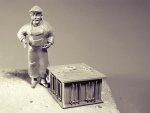
While I'm re-doing the spindle, I'm thinking about the pawls for stopping the unwinding of the capstan. I've looked at dozens of capstan layouts. The one Dan Vad did on his Swan class boat is far and away the simplest.
The pawls resist at the bottom of the whelps. They would be "kicked into place" by the nearest seaman. I realize this is 50 years or so older than the Anchor Hoy, but it is an effective, inexpensive solution for a harbor work boat. Any comments?
Maury
-
kees de mol reacted to Maury S in Anchor Hoy c. 1825 by Maury S - FINISHED - 1:48 - Harbor craft - POF
The barrels and whelps are done...better.
The drumhead is next and I need more experience on the lathe and mill. I have a 3-jaw chuck so I took a piece of square stock of pear down to eight sides, then 16 to get close to a round piece that will fit securely in the chuck. I turned it down to the right diameter then transferred the chuck to the rotary table on the mill. When tightening, I mistakenly loosened the chuck so knowing it was scrap, I continued on and milled the slots for the bars as practice. Going back to the lathe showed how an ever-so-slight loosening of the jaws threw everything off. I had a bit of a problem parting the piece (burning and binding), so off to YouTube for hints and techniques. Perfect alignment, half the rotation speed and a slow feed of the parting tool.
Second attempt:
Two pieces, the bottom one milled for the bar slots and parted off on the lathe. The top one finished on the lathe with a slight crown and a ring for a reinforcing band. Everything still in just test fitted. Next the base for the pawl ring.
Maury
-
kees de mol reacted to Maury S in Anchor Hoy c. 1825 by Maury S - FINISHED - 1:48 - Harbor craft - POF
Whelps and chocks installed. OK for a first attempt and I can do better. The chocks don't line up perfectly and I know I'll regret it if I don't do them again. When I started the barrel on the mill, I figured it was a test run so here I go again.
Back to the equipment and a better result.
Maury
-
kees de mol reacted to Maury S in Anchor Hoy c. 1825 by Maury S - FINISHED - 1:48 - Harbor craft - POF
The waterline was defined with Tamiya tape and the first two coats of yellow / ocher between the wales and the waterline.
A few more coats and then I'll paint the "White stuff"...
Maury
-
kees de mol reacted to Maury S in Anchor Hoy c. 1825 by Maury S - FINISHED - 1:48 - Harbor craft - POF
The wales are in. Minor sanding and a few repairs then to finishing the transom.
-
kees de mol reacted to Maury S in Anchor Hoy c. 1825 by Maury S - FINISHED - 1:48 - Harbor craft - POF
No secret to clamping in areas where regular clamps do not reach. Rubber bands and some blocking do wonders. Be careful that the bands are held on beams (see ends of two sanding sticks in the picture below). Wrapping the bands around the entire hull puts undue strain on the rails and pulls them in. You can increase / decrease pressure by shifting the bands. The parallel clamps hold the two planks together, even though they mate perfectly. This is the aft end of the second wale plank going on.
Maury
-
kees de mol reacted to Maury S in Anchor Hoy c. 1825 by Maury S - FINISHED - 1:48 - Harbor craft - POF
The Whiskey strake is in. I haven't had any "whiskey" since St. Patrick's Day, but I think we'll have some margaritas tonight. Some minor hairline cracks are visible between a few planks and I'll run some very diluted glue into them and rub in some fine sawdust. Some more sanding at the bow and stern and I can start work on the counter and the wales.
You can see the frames in the section I did not plank.
Maury
-
kees de mol reacted to Maury S in Anchor Hoy c. 1825 by Maury S - FINISHED - 1:48 - Harbor craft - POF
Thanks for the input! I guess I mis-read my other source. I can shift things around but I'd prefer not to remove the first strake above the garboard. Changing to 3 strakes between makes fewer joints and gives me only one little wrinkle to the pattern at frame 19. I'll re-do to accommodate the appropriate guideline. It all gets painted over so I'm not highlighting the seams.
The spiling pattern for the first starboard strake above garboard (see Primer on Planking by David Antscherl ) and the resulting plank with the required twist is shown.
It can be seen installed below. No ugly gaps between planks. There is some minor surface sanding yet to be done near the bow, but it's one of the better joints I've made. Every time is a learning experience.
Maury
-
kees de mol reacted to Maury S in Anchor Hoy c. 1825 by Maury S - FINISHED - 1:48 - Harbor craft - POF
Druxey, Yes, it's going to be a challenge. Once the garboard plank is in, re planning the layout of planks at the bow can begin.
The garboard plank has severe twists both at the bow and the stern. The bow portion was laid out in card first, transferred to wood, then adjusted to run fair.
Then the stern portion was shaped and twisted (hot air machine and gentle twisting).
Edge sanded where it enters the rabbet and glude in place.
THe center portion was then fit.
It needs some final sanding, then on to the other side.
Maury