HOLIDAY DONATION DRIVE - SUPPORT MSW - DO YOUR PART TO KEEP THIS GREAT FORUM GOING! (Only 51 donations so far out of 49,000 members - C'mon guys!)
×


timboni
-
Posts
58 -
Joined
-
Last visited
Content Type
Profiles
Forums
Gallery
Events
Everything posted by timboni
-
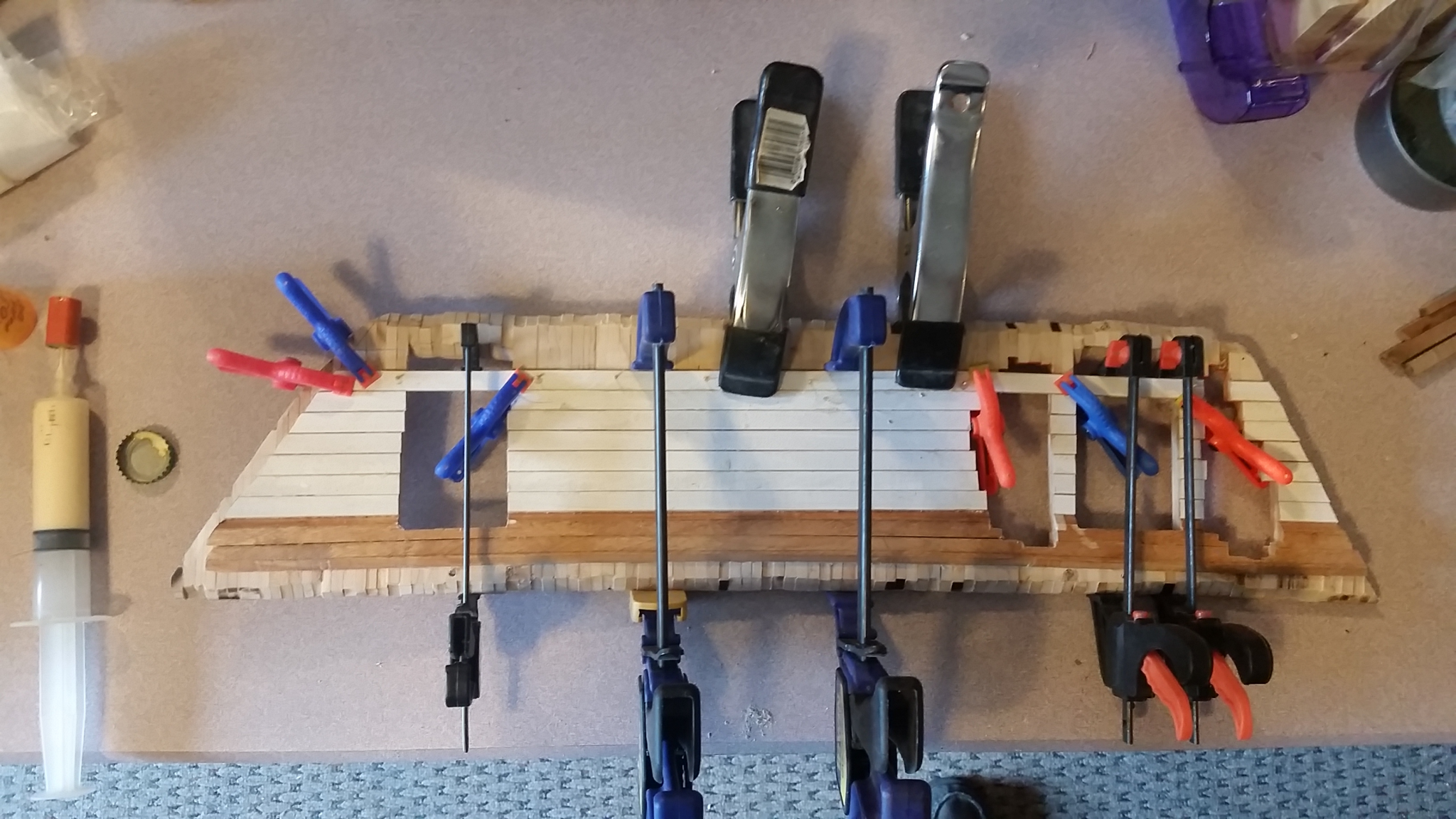
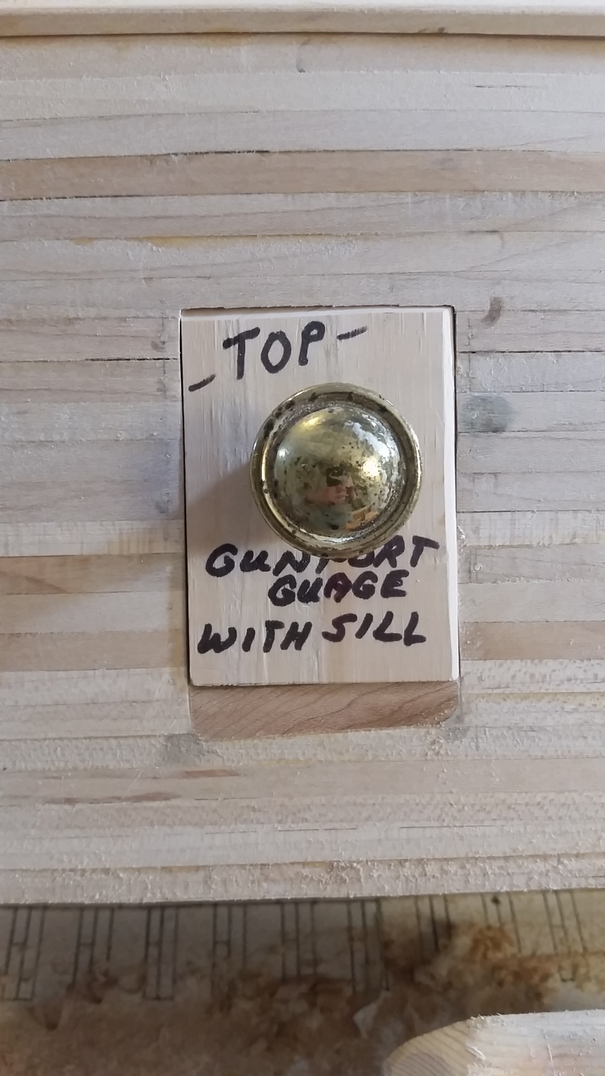
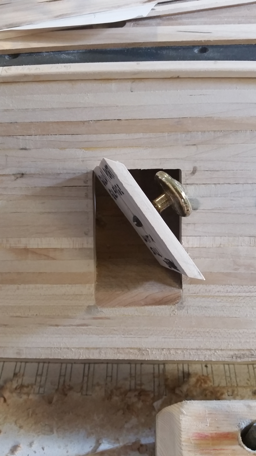
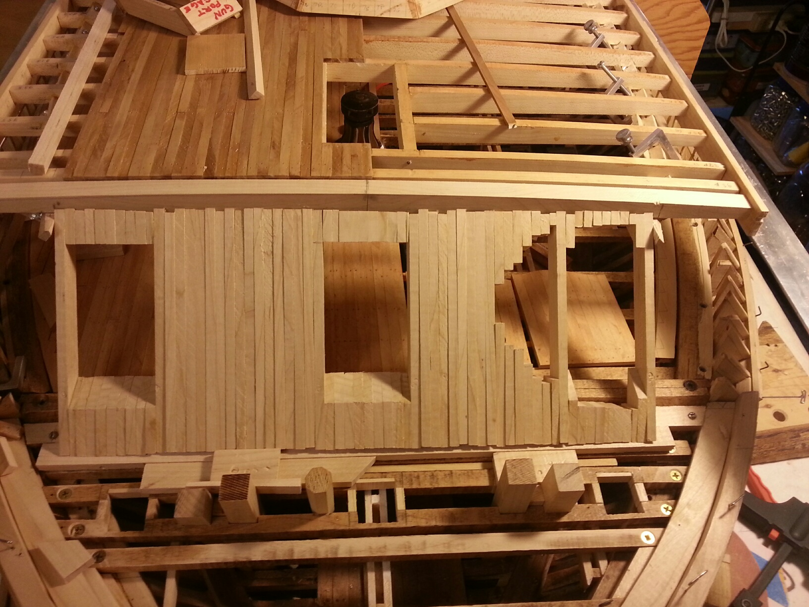
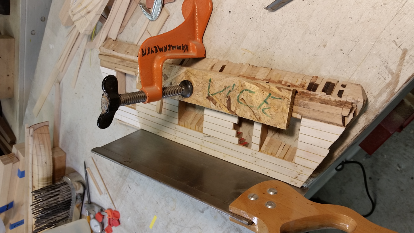
Hi all, hopefully this posting will go through; been having some problems getting the pictures to work. Apologies for the extreme delay, as my previous posting was back in January of 2019. The pictures below are from May of 2019. All pictures and text are by Bill Kammermeyer. And here we go! Stern casement ceiling being installed. Glue , clamps and tree-nails hold the camber (90 degrees off). Removing the interior tabs on all of the front casement timbers to allow it to be installed with the horizontal timber and armor plate in place. As it was this was impossible due to the curve of the bow construction. Bow casement ceiling (1st coat of white wash) has been installed. Edges at gun ports and cut outs to be finished later. Gun port gauge to show the interior shape of the port Fit of gauge in each gun port to insure uniform size and rectangular shape OK, I'm going to post this and see if it goes through. If so, got MANY more pictures for you. Tim Jovick


-
Well, well, well! Looks like my copying and pasting the original picture from the email ends up as a link, but the download works! Any comment from your end?
-
OK, here we go: The way I had done it is to take a picture from an email sent to me, click on it and right-click on that picture, click Copy Image, then Paste in this forum. Here's an example: Alternately, I guess I could download the picture and copy and paste from that. Here's the same picture in that format: In this format (which I hadn't used before), the picture comes out bigger and takes a bit of time to upload to this format. The image on the left is what showed up when I just clickedabove and entered Paste. The one on the right happened when I clicked Choose Files and then went to my downloads and found this. Look identical, but I may be wrong. So let's see what we got here!


-
I have ben attempting to enter into the build log for the Gateway Shipcrafters USS ST LOUIS Civil War Ironclad . When I did so previously (January, 2020), it went smoothly. This time, I entered a number of photos and captions, but when I entered "Submit," it didn't work. When I reviewed my entry, the pictures were in the form of links. And I can't submit even with the links. I don't know if this is a login problem because the website seems to recognize me. I sent an email to Kurt, but haven't heard back, perhaps it's an old email address. Any help would be most appreciated.
-
Well, OK, looks like I ended up with some duplicates of photos at the end of the posting. but if that's my worst sin, I"m OK.
-
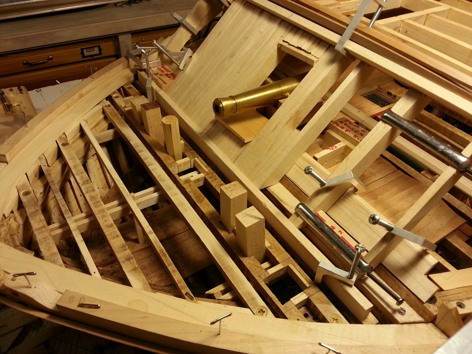
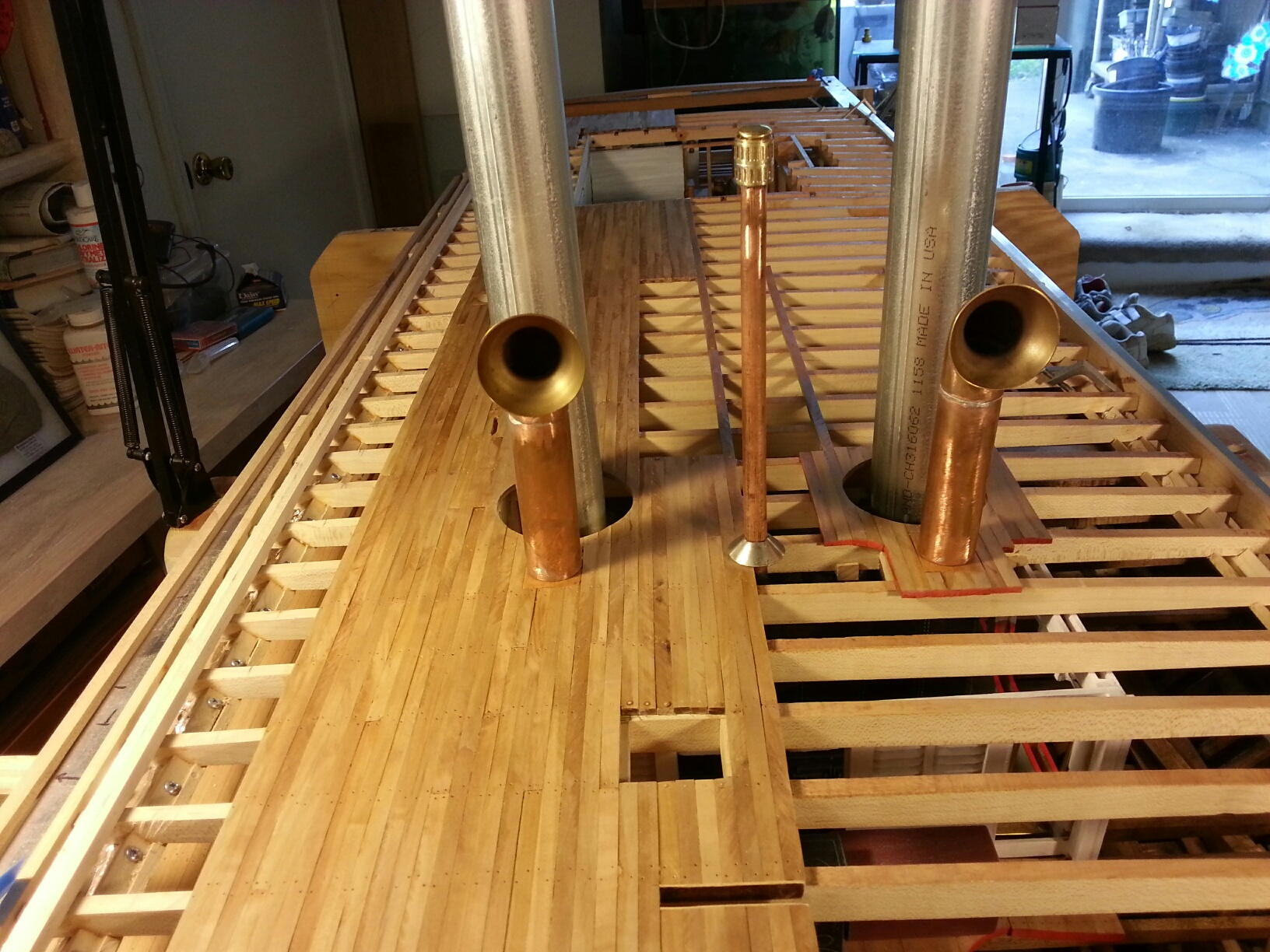
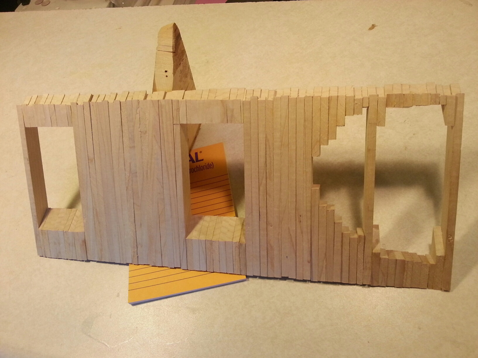
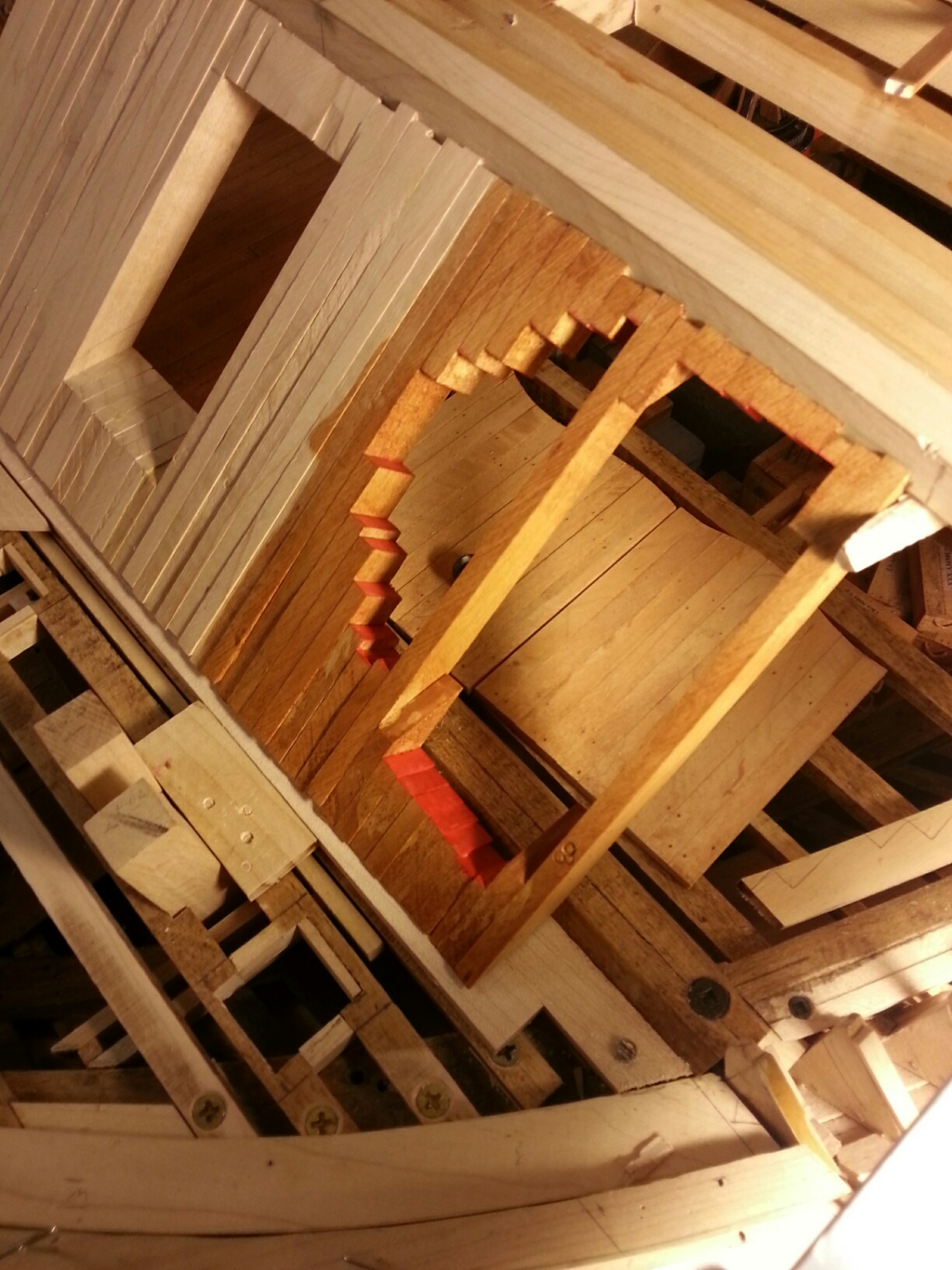
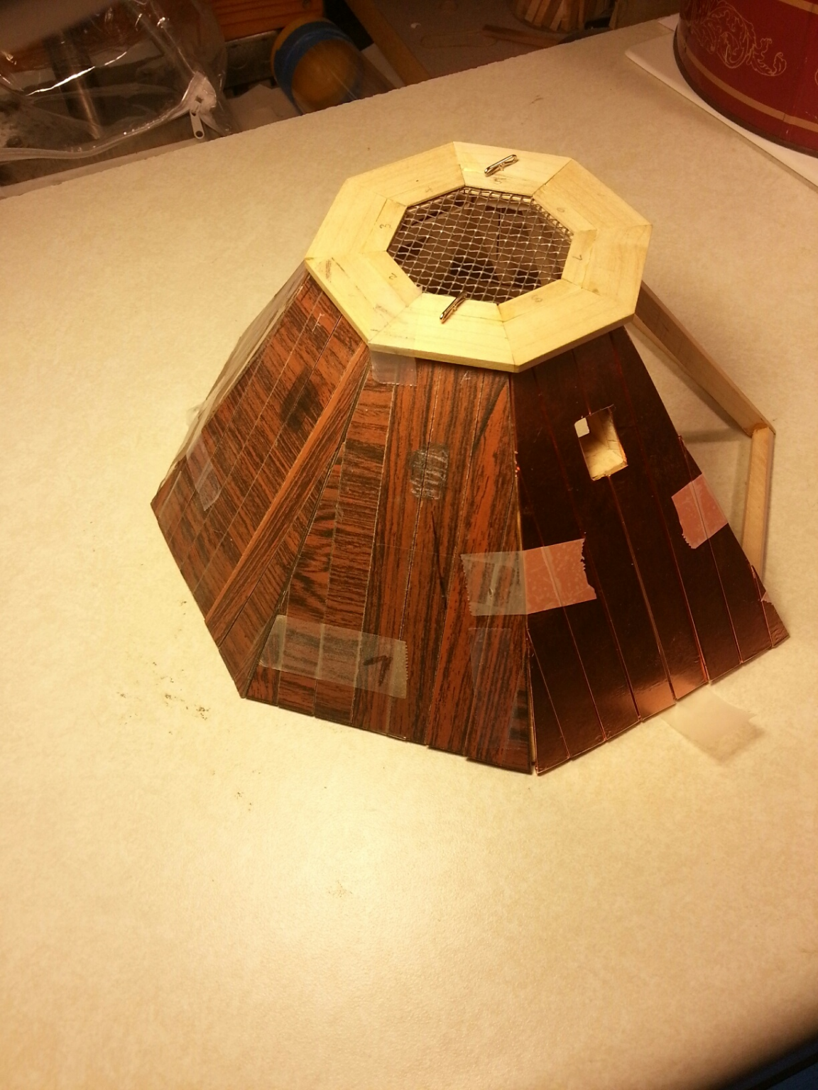
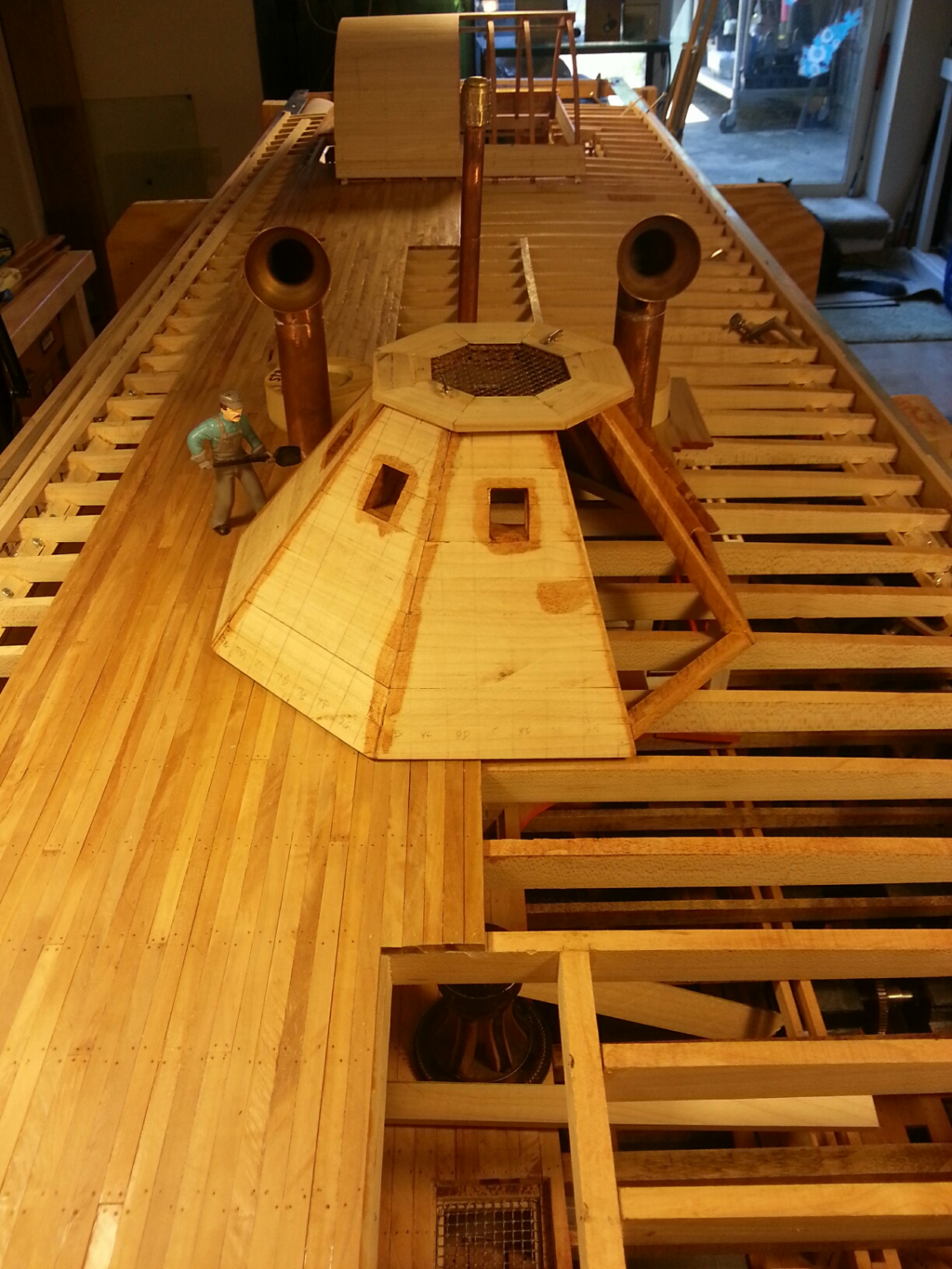
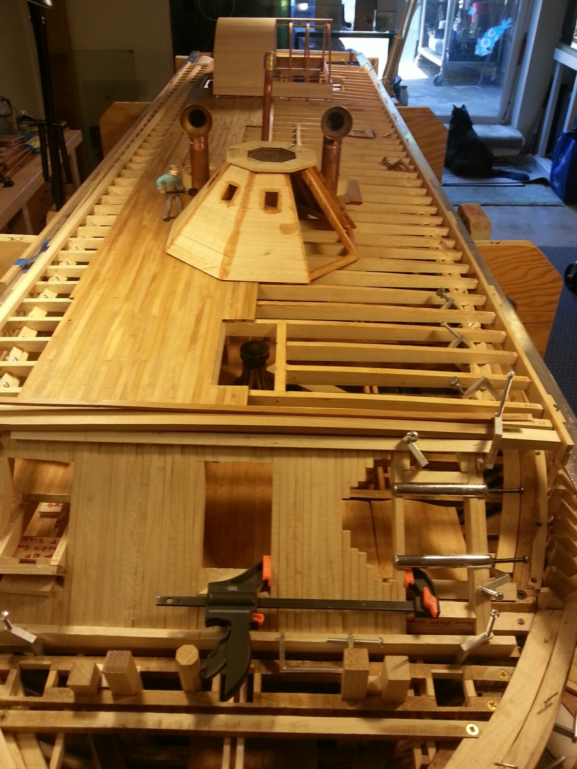
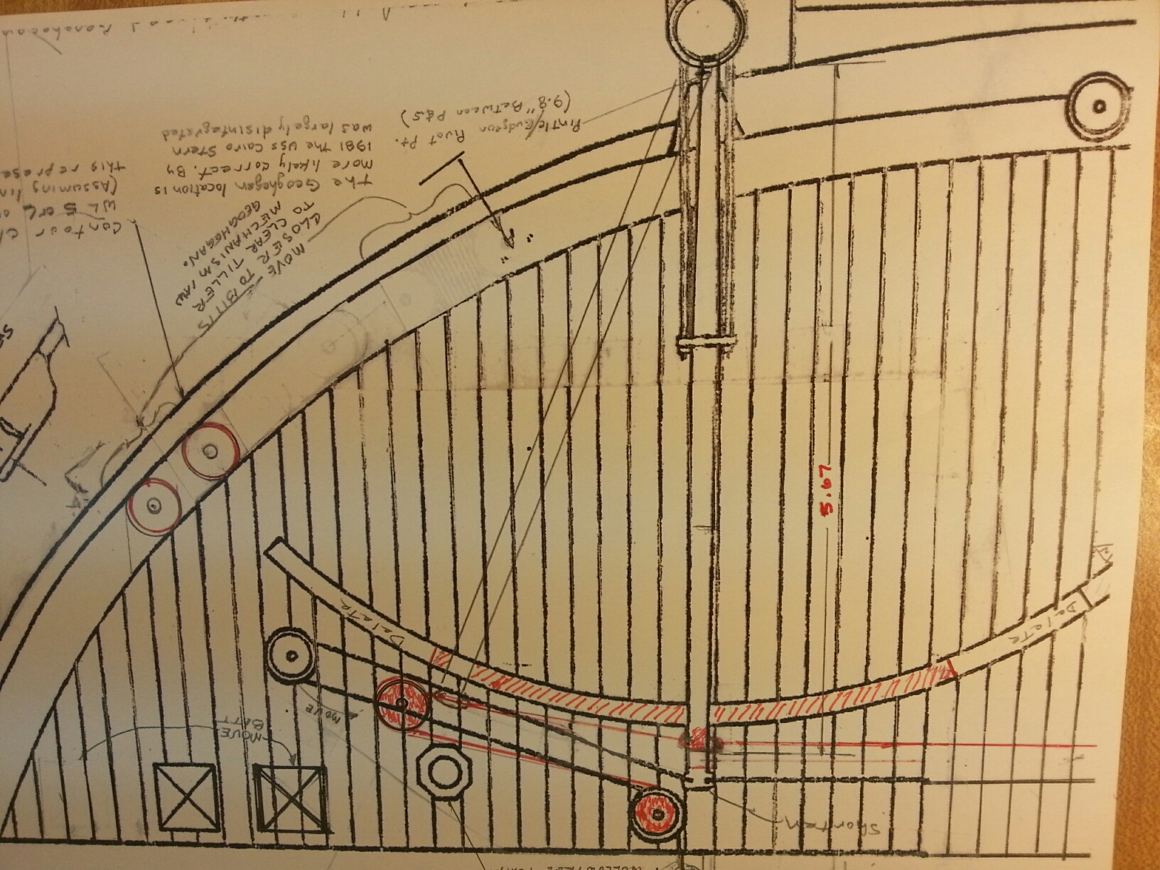
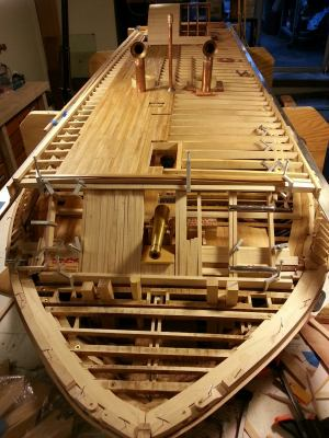
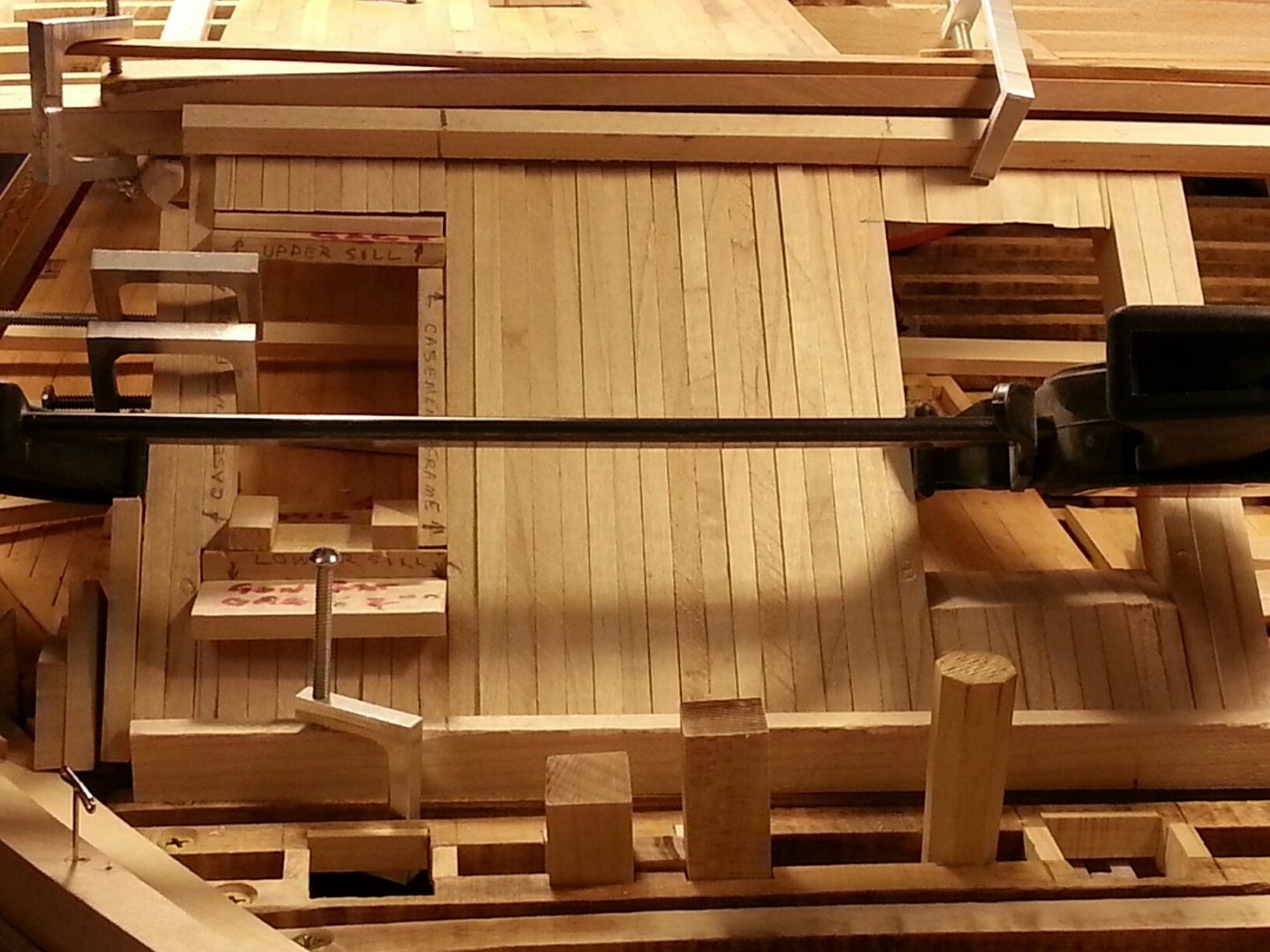
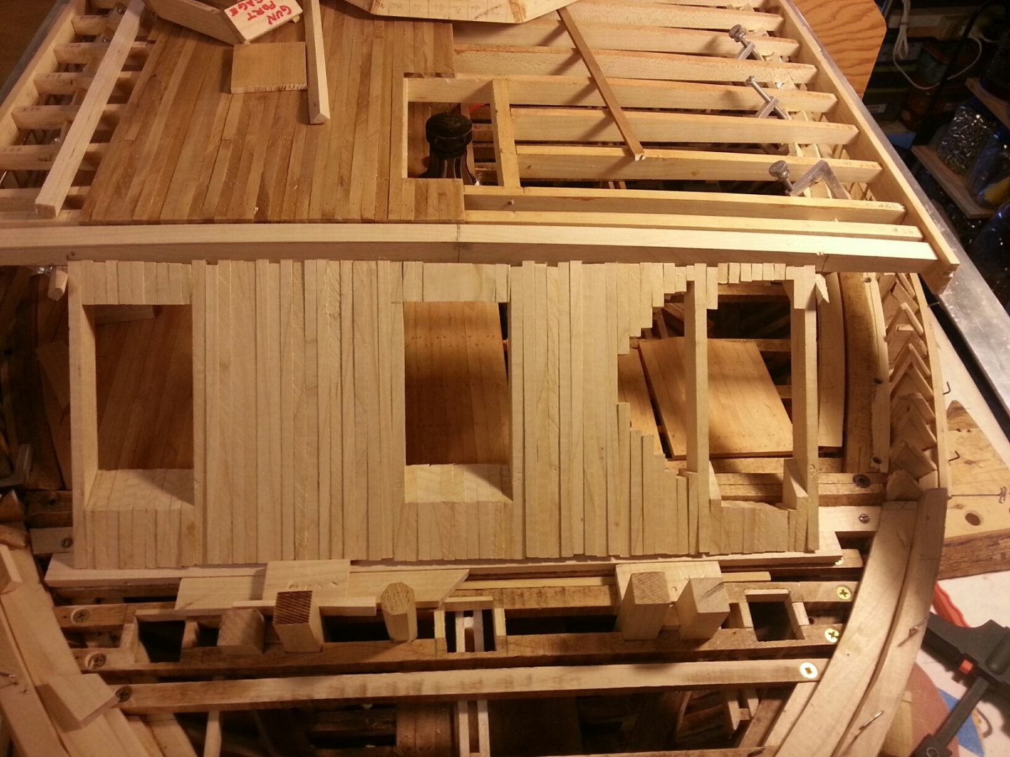
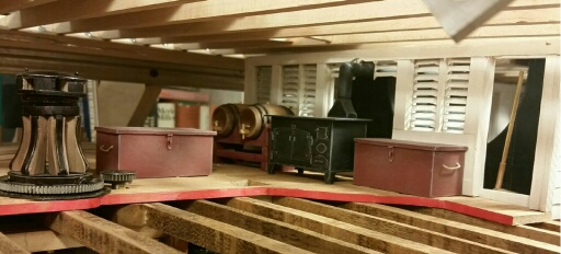
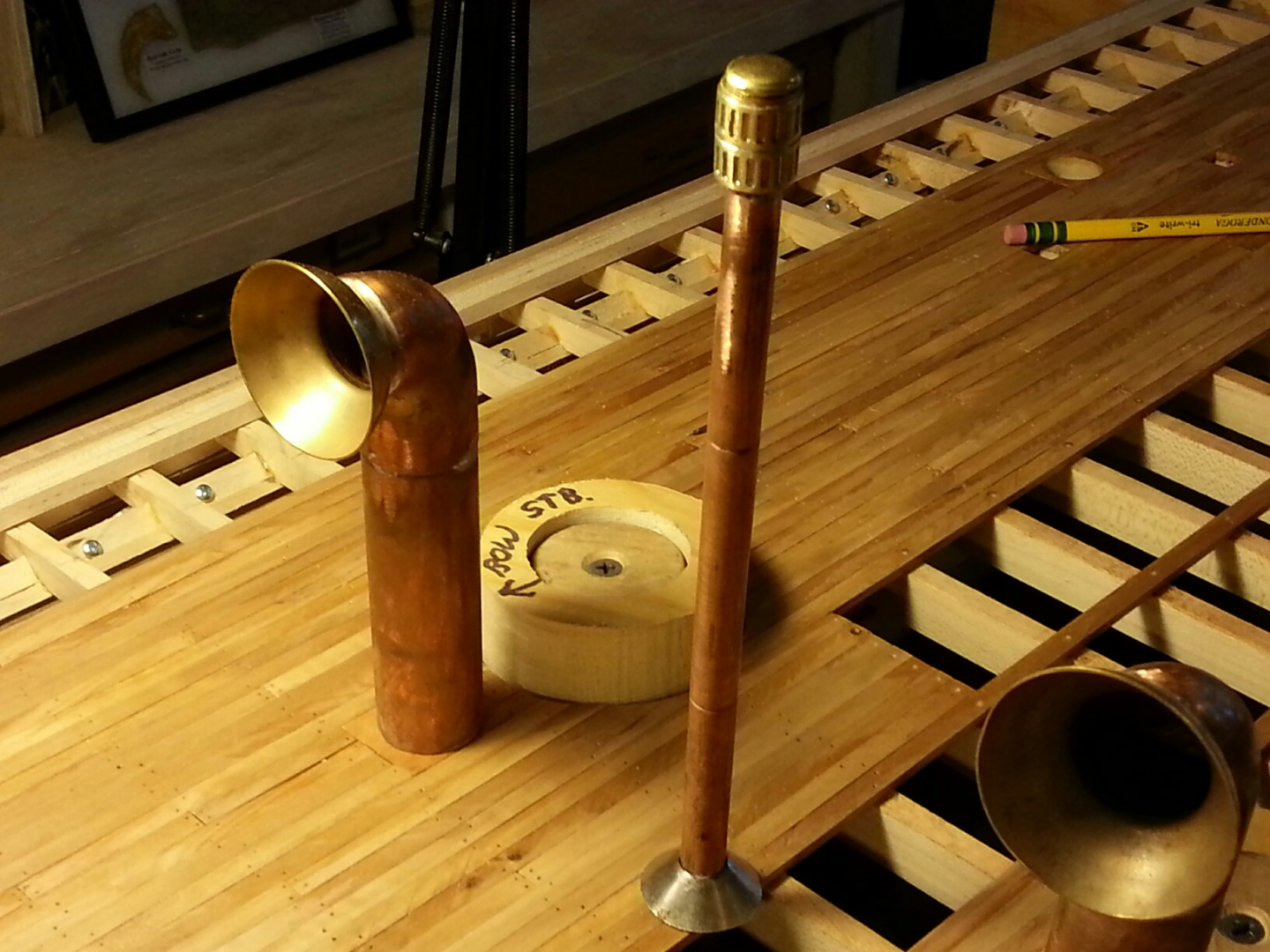
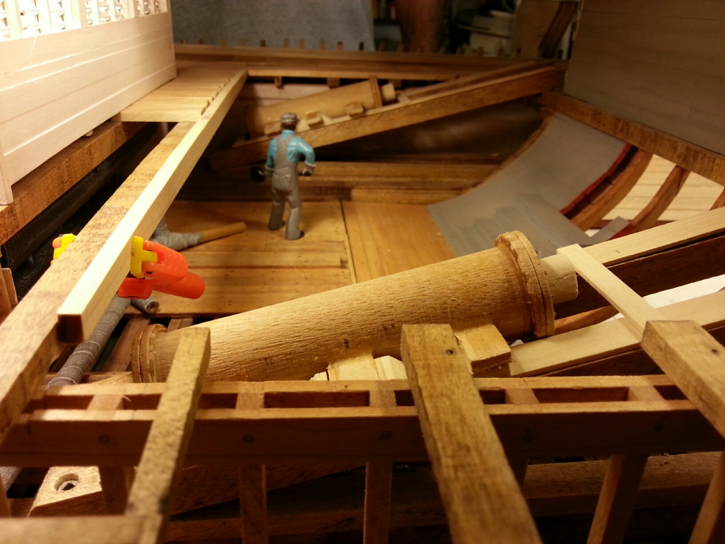
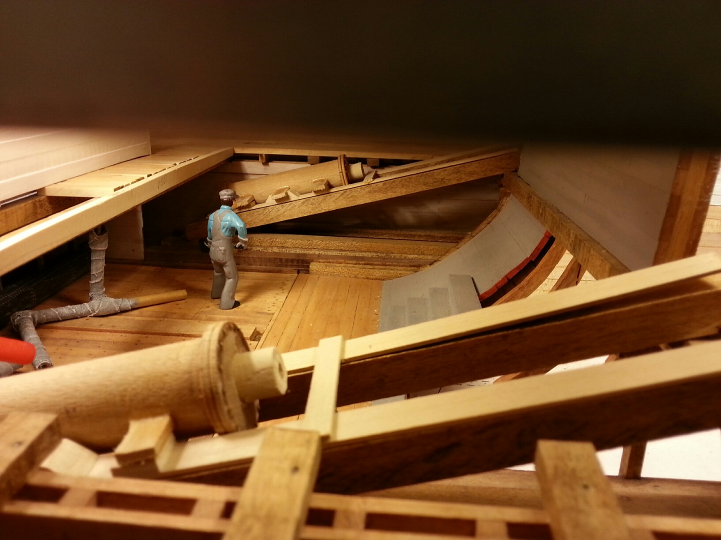
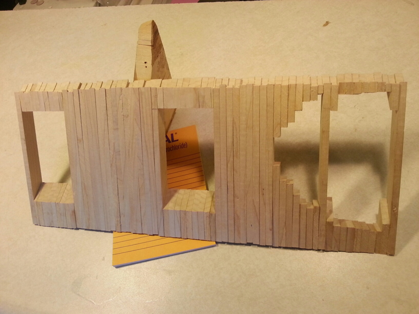
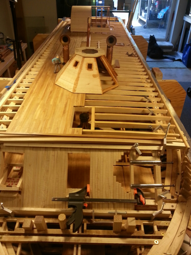
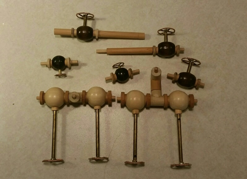
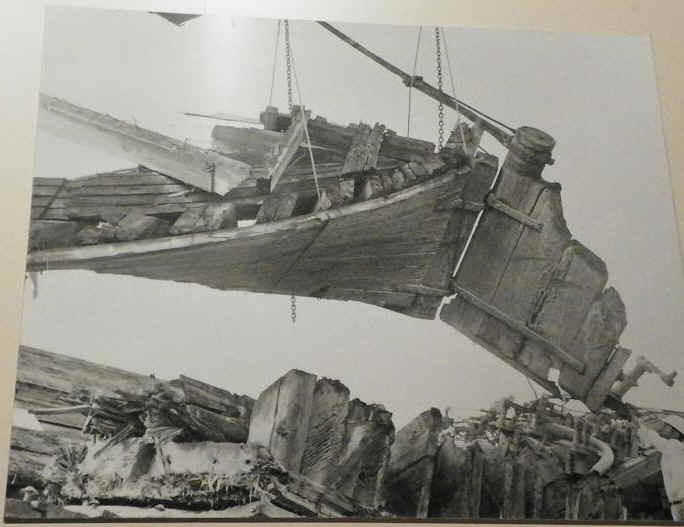
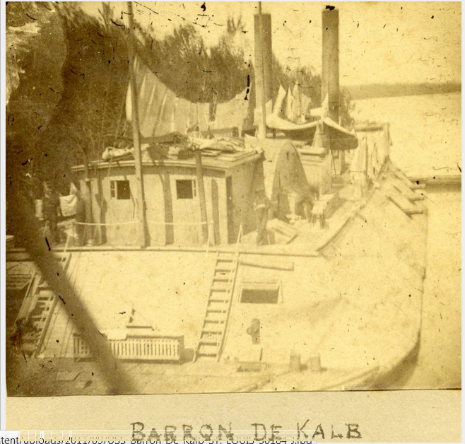
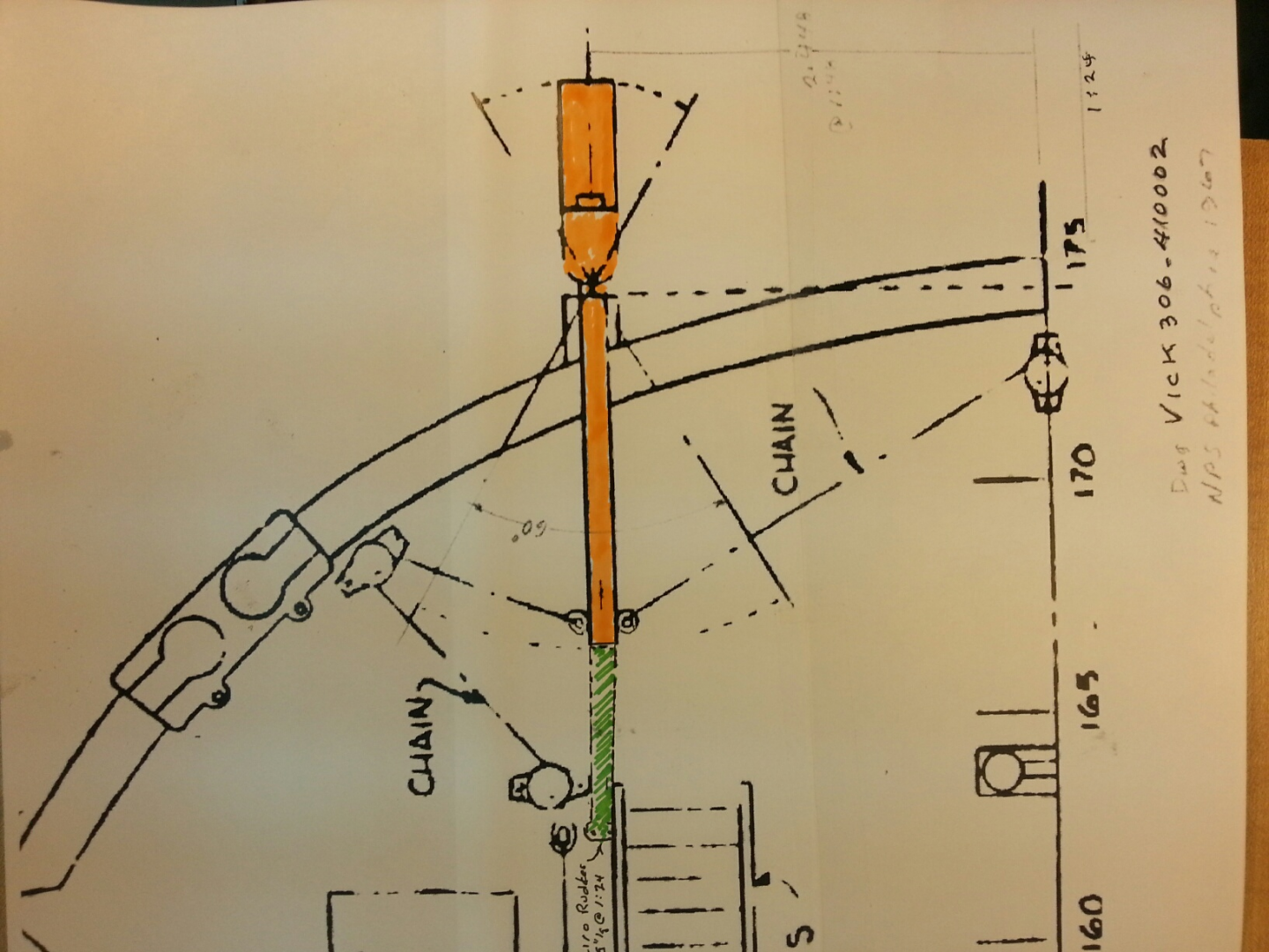
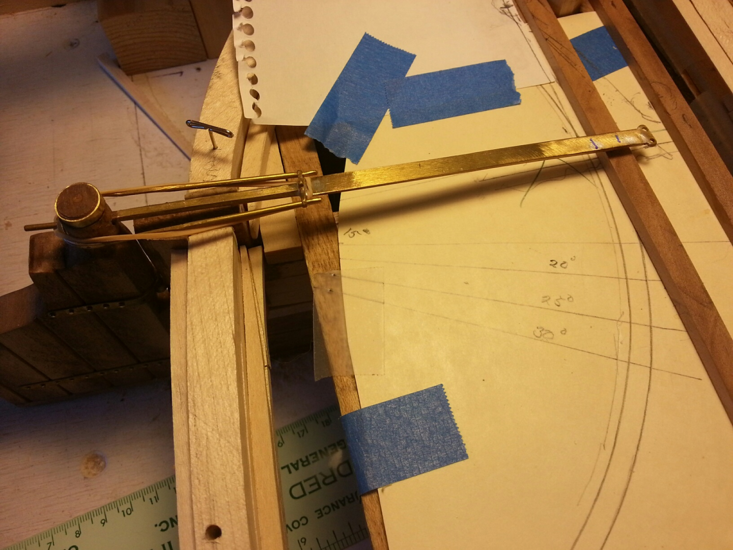
Hi all, this is the first installment of our "catch-up" for our Build Log for the USS St. Louis. This is a summary for our work as of August, 2018. All of the text and pictures are by Howie Smith. I'm going to try to have these pictures with appropriate captions, so here we go! Would be glad for feedback, as this is my first attempt at contributing to this build Log. Apologies for any inaccuracies. My email is timboni@juno.com Tim As part of an overall review of our USS St. Louis ironclad topsides, we focused on the forward 45-degree casement sub-structure with the brass 42-pdr Rifled Cannon Barrel on its carriage dry-fit in the centerline gun port. (Photos 1 & 2). We then proceeded to outline the remaining process for constructing the removable center section of this casement which originally consisted of a solid stack-up of vertical beams(Photo 3) between the outer sides of the P & S gunports covered by similar stacked horizontal beams, and then vertical iron armor plates, which totaled up to a thickness of 25-inches. Our model will duplicate this construction on the starboard side past the centerline structure (Photo 4 ) and then diminish by layers on the port side to reveal the underlying structure. This section will remain removable to maintain access to the gun deck until final stages of model assembly. We also reviewed the positioning of Vince & Tim’s galley stove and associated furnishings on the gun deck (Photo 5) and Bill’s exhaust stack thru and above the Hurricane deck (Photo 6 &7). This was followed by a second dry-fit of Bob’s port & starboard main steam engine cylinder wooden cores in the engine room, on their support ramps (Photos 8 & 9). The first stage of the bow casement, consisting of the vertical beams and gun port framing for the removable center section has been completed (Photos 10 & 11). The red beam edging indicates intentional disruption of structural members to reveal underlying or internal model features The second stage will consist of attaching a layer of stacked-up horizontal beams which include a similar diminishing effect as their ends near the port side. We spent a considerable amount of time discussing Tim & Vince’s problems cutting out the thin triangular strips of .030” thick Fomica substrates for the pilothouse armor plates and after a few experiments, it was decided that rather than sawing or cutting, a belt sander was the best solution and Bill graciously agreed to provide them a 1-inch table model belt sander to use for this purpose..Vince and Tim have made excellent progress shaping and fitting the Formica substrates for the pilothouse armor plates (Photo 12). They also have added .002” thick copper foil to the substrates for one of the octagonal pilothouse’s sides as seen in these photos. The foil will be chemically blackened and secured in place using the simulated ¾” bolts and washers previously stamped from No. 18 Escutcheon pins. The pilothouse has also been dry-fit to its location on the Hurricane deck to verify its proper relationships to the ventilation funnels, galley stove exhaust stack, skylight and forward casement.(Photos 13 & 14) Bill has developed and fabricated a series of improved steam pipe shut-off valves and control wheels (Photo 15) which will be integrated into his steam distribution piping system Activity will now shift to construction of the stern 45-degree casement and laying planking on the stern deck itself. As a pre-requisite, we decided to revisit the stern deck nautical operations, equipment locations, and functional geometry before committing to casement and decking configurations. None of the existing published aft deck drawings appear to depict a completely satisfactory operating geometry that is also compatible with the few existing contemporary photographs. This includes the 4 mooring bitts, 4 tiller control chain rollers, tiller arc of travel , tiller support roller track and bulwark mooring line guides. At the heart of this issue, it appears that the tiller was lengthened sometime during City Class ironclad construction but the resulting mechanism geometry wasn’t adequately documented. Since the USS Cairo iron tiller(Photo 16) was recovered with the USS Cairo and a photograph of the USS DeKalb(Photo 17) locates the bitts, our stern deck reconstruction utilizes these two features to locate the remaining elements to establish rudder travel which was reportedly inadequate in any event. National Park Service (NPS) drawing dated 1967 for the USS Cairo (Photo 18) depicts a short tiller (Colored orange to which we have appended its actual length in green) and its resulting geometry. Our reconstruction geometry is over-laid in red upon the NPS drawing dated 1981 of the USS Cairo (Photo 19) and depicts the maximum rudder travel achievable using the recovered tiller length and will remain the basis for our USS St. Louis model (Photo 20).


-
Hi all, Just letting you know I'll be taking over the updating of this build log from Howie Smith. I'll be posting a number of progress notes, from early 2019 through the present, with pictures and captions by Howie Smith (aka John Howard) and Bill Kammermeyer, credited. Hopefully this will be a smooth progress despite Murphy's Law. If anyone has any questions, please feel free to email me at timboni@juno.com or call me at 314-761-5435. Tim Jovick Secretary Gateway Ship Crafters Guild
-
Wow! For philo426. Looked at your album, very impressive! Have a musty, incomplete kit, looking for a building log. Very interested in the transom, as there wasn't a drawing in the plans we have, and the photo was blurry. Thanks for posting this, may consult you along the way. Tim Jovick