timboni
-
Posts
58 -
Joined
-
Last visited
Content Type
Profiles
Forums
Gallery
Events
Everything posted by timboni
-
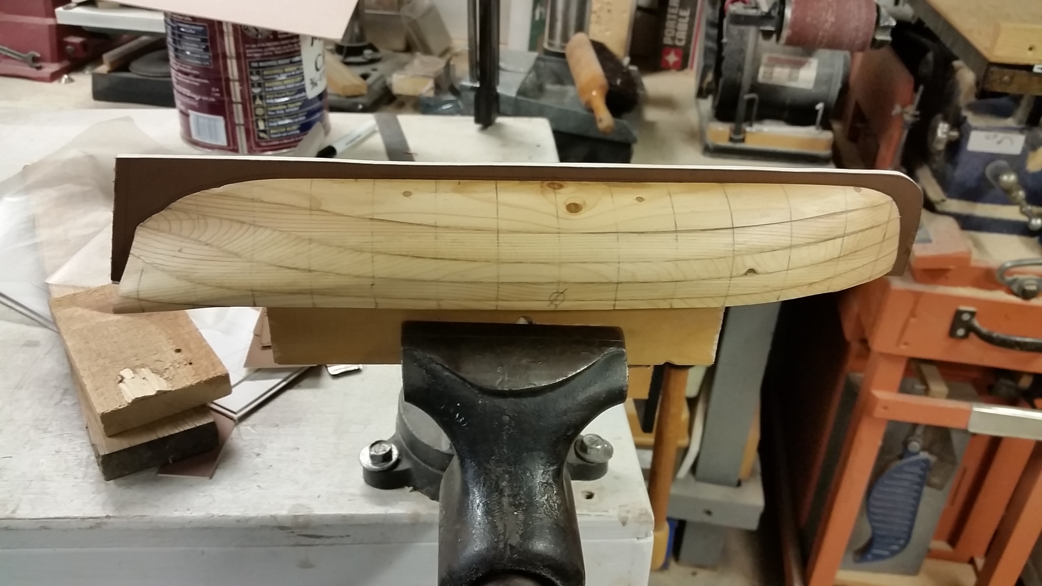
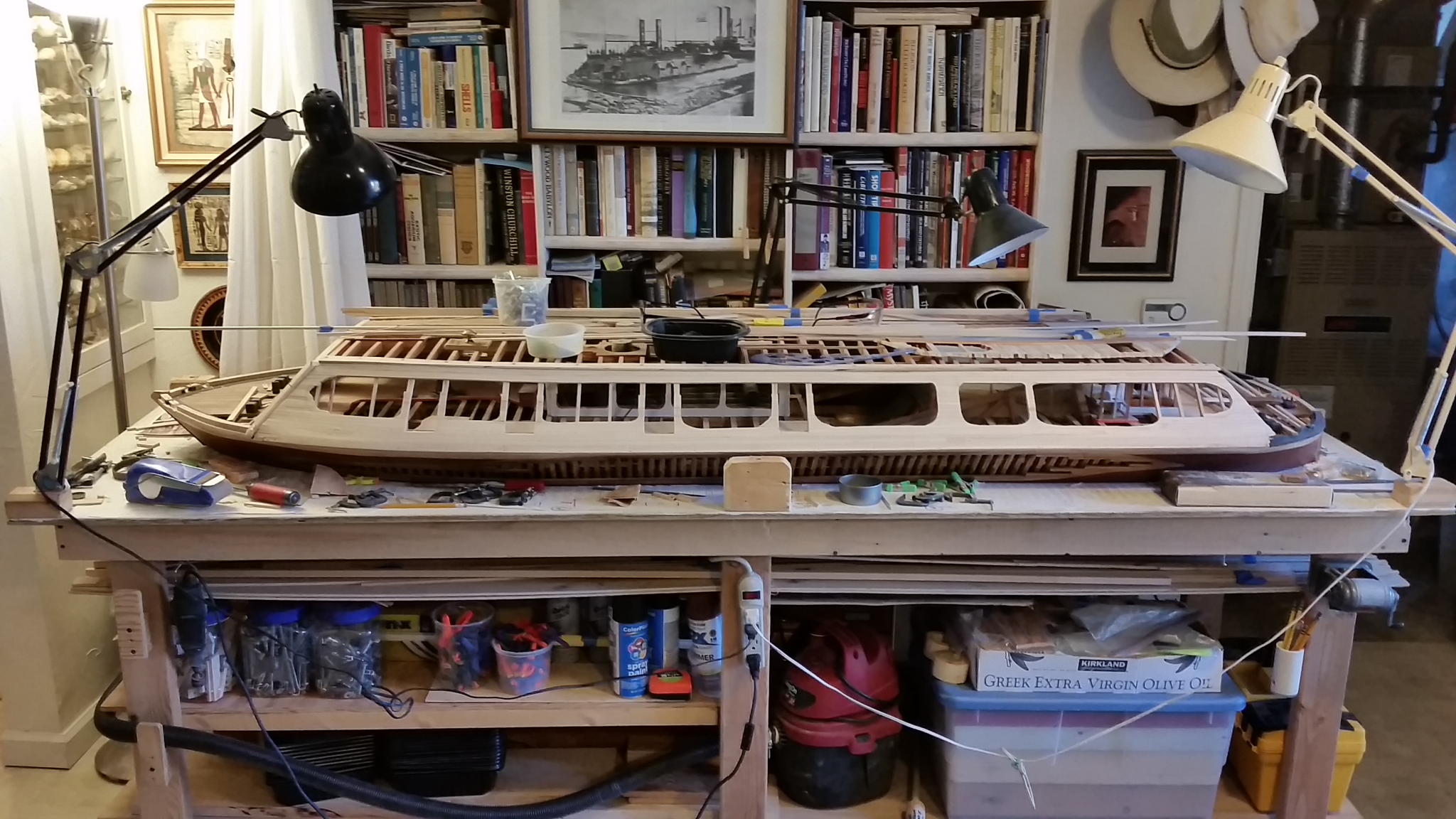
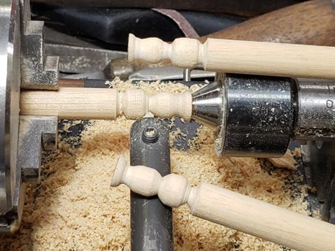
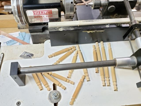
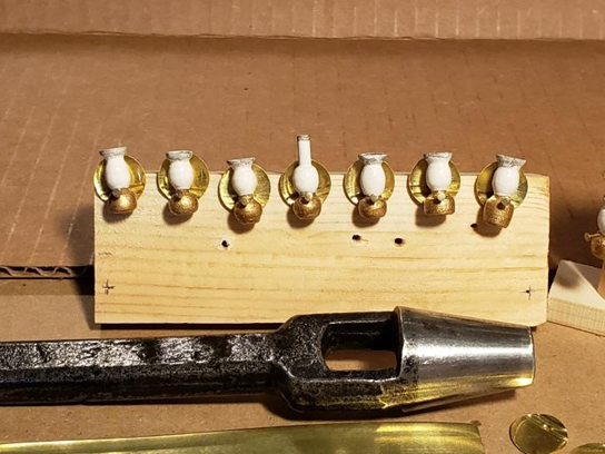
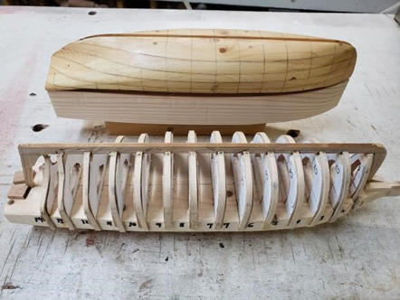
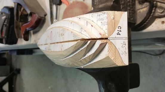
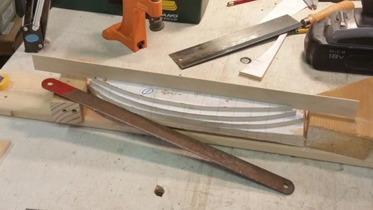
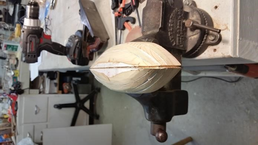
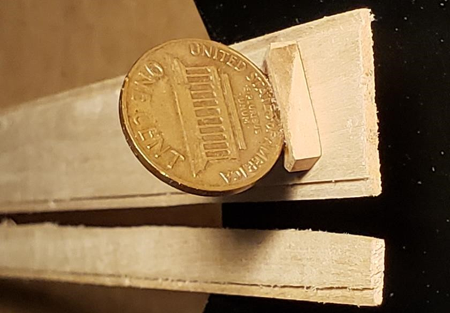
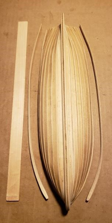
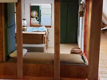
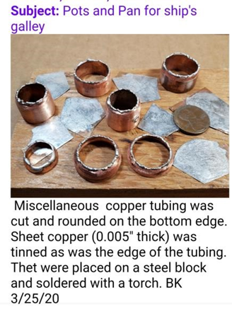
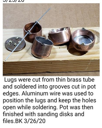
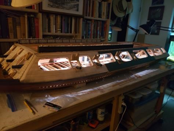
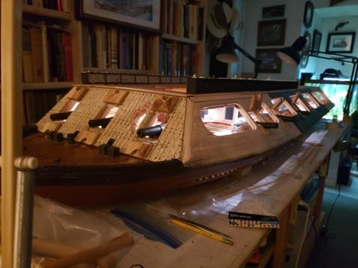
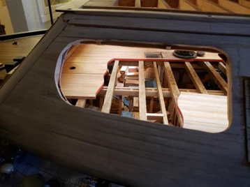
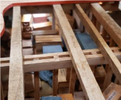
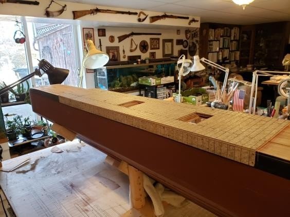
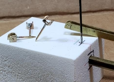
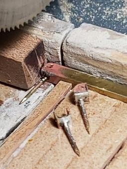
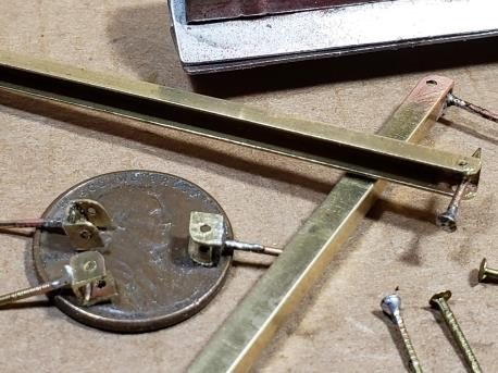
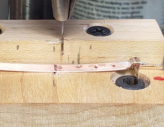
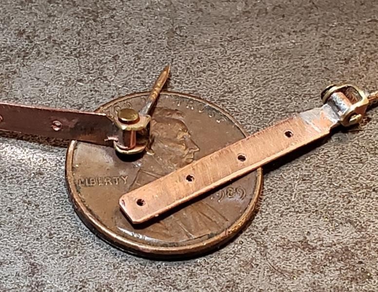
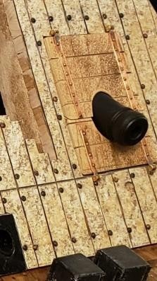
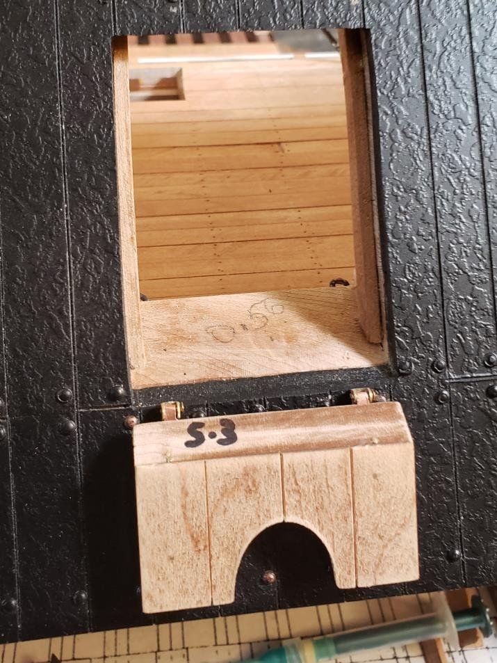
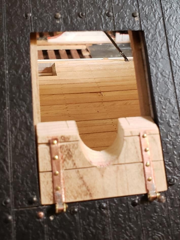
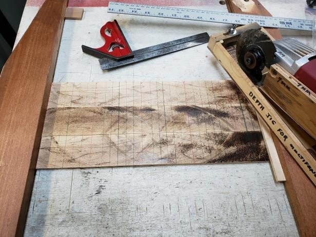
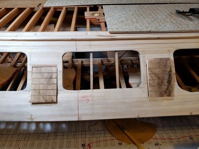
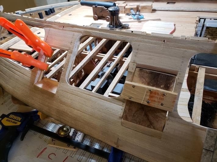
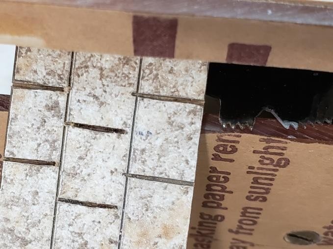
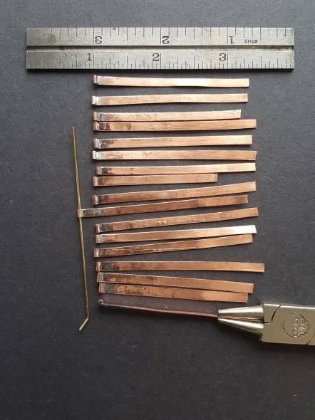
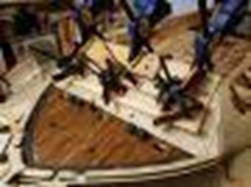
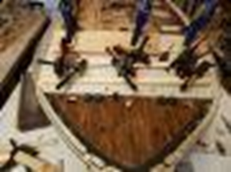
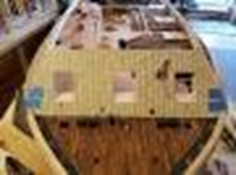
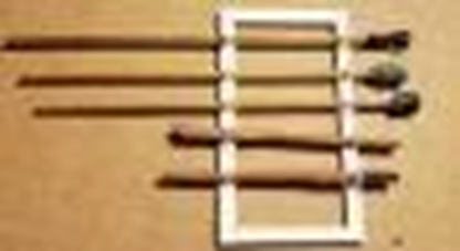
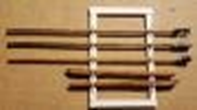
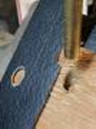
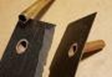
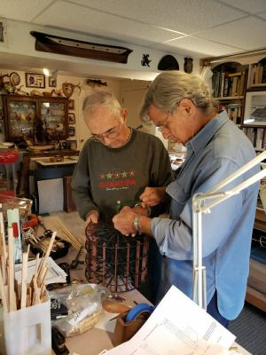
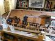
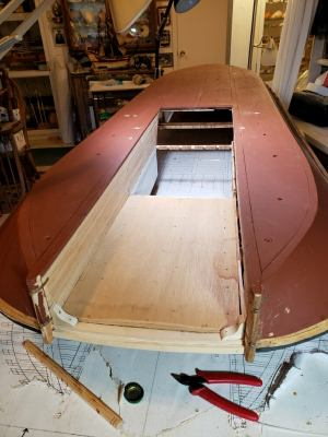
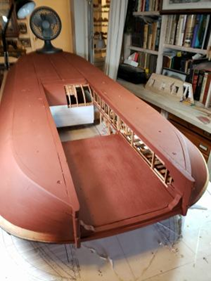
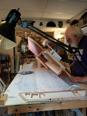
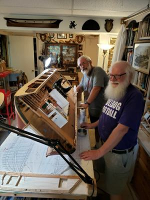
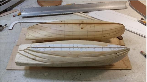
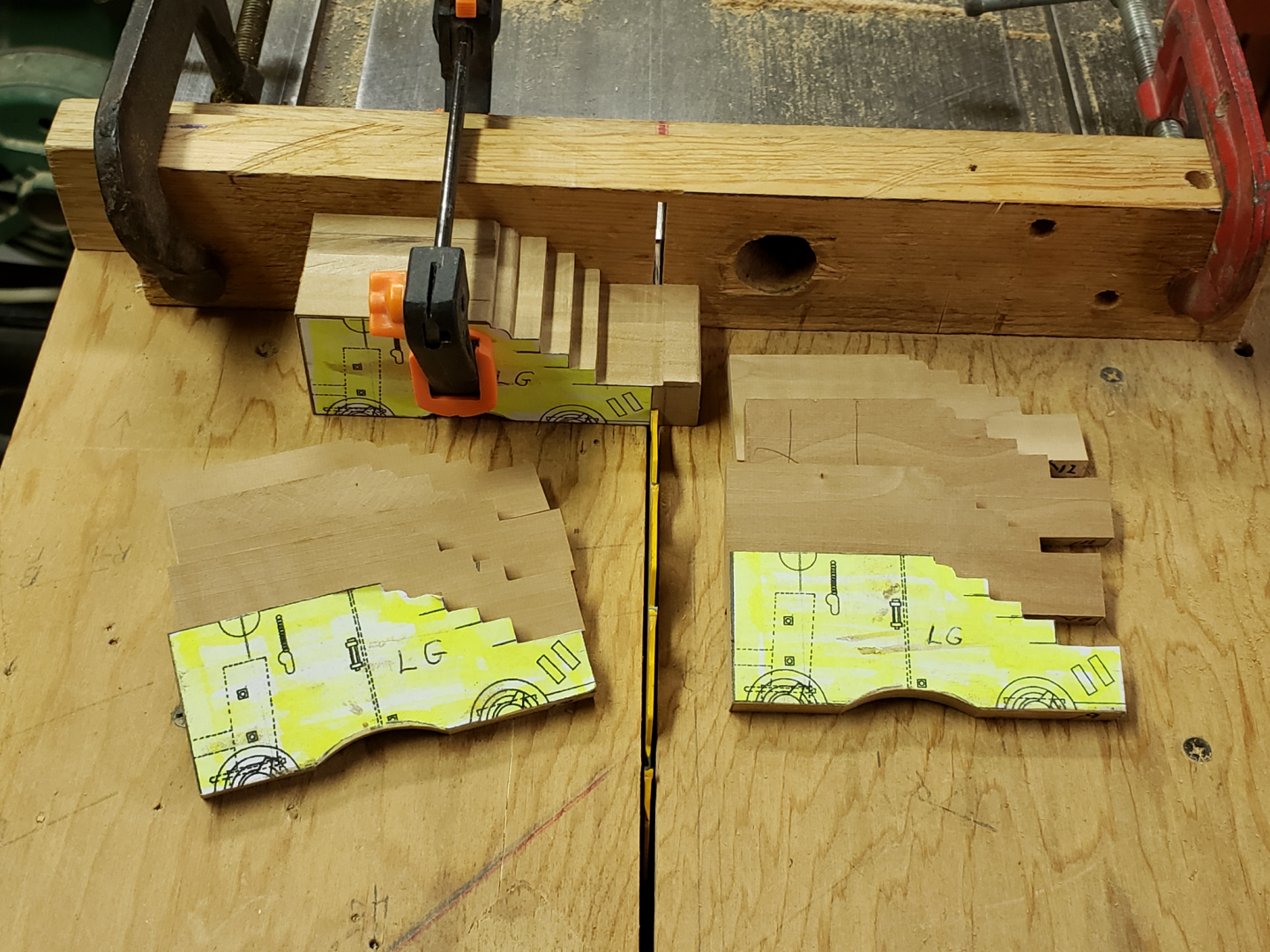
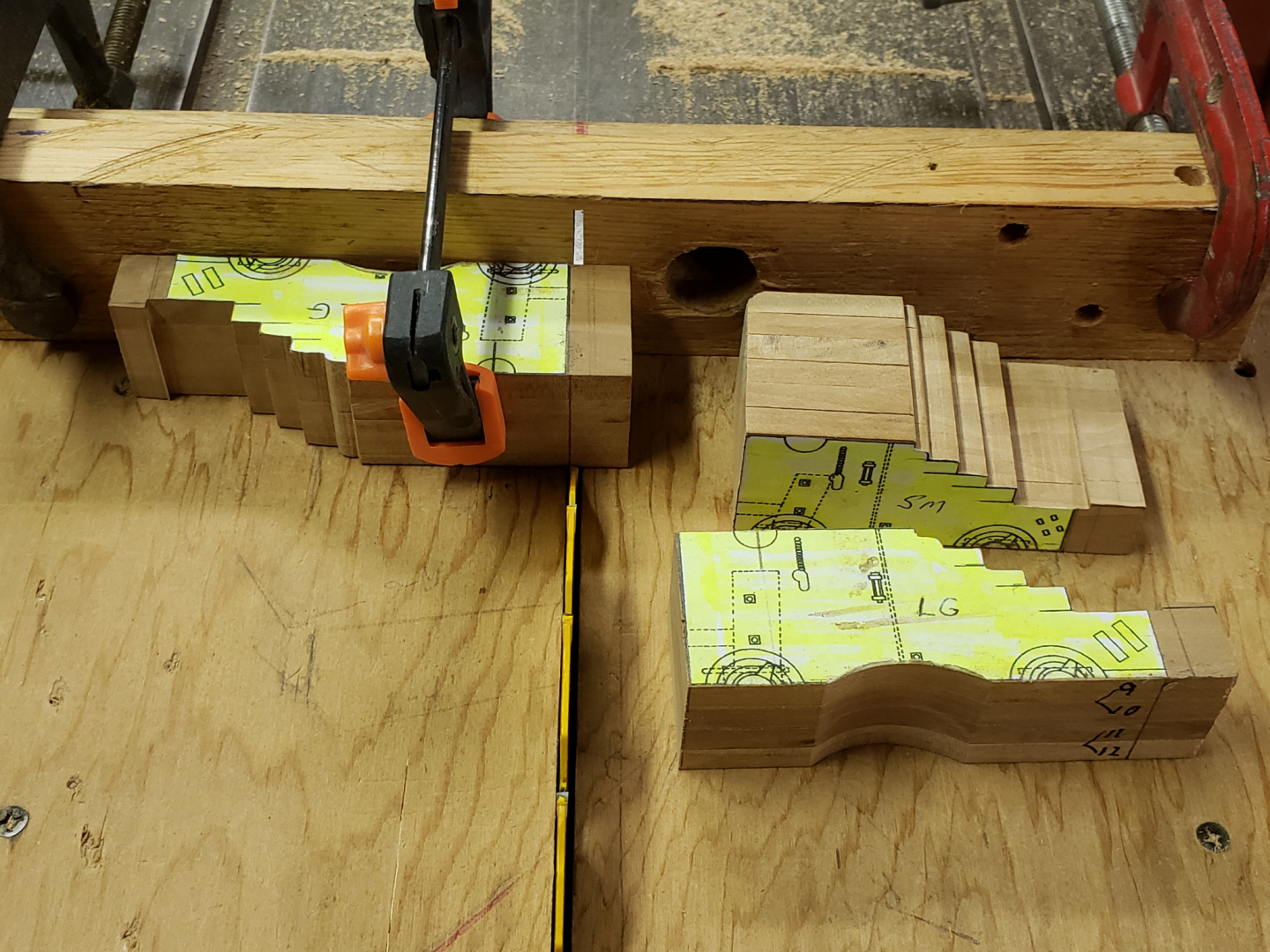
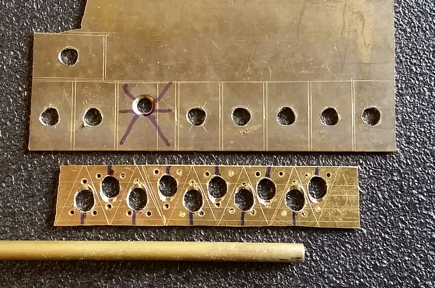
The following entries are from about June or July of 2020. Again there were not meetings due to COVID, but Bill Kammermeyer continued to work on his own. Pictures and captions are by Bill. Making Internal Lanterns: Using my pattern duplicator on my Sherline lathe, I cut 25 lamps from 5/16" dowels. The ends were countersunk to make the internal taper. I finished their shape with files and sandpaper. Leaving them on their dowels made it much easier to varnish, re-sand and paint the lamps. A 1/2" punch was used on a strip of brass weather stripping to cut the reflecting backs for the hurricane lamps. Pins were pushed through pre-drilled holes in the lamps as well as the reflective plates and super-glued in place. This made not only the wick-adjusting knob for the lamp, but also the attachment for the back plate as well as a mounting fixture to go into the walls along the inside of the ship. Penny for scale. Painting and drilling accurate pin holes were easily done while the lamps were still on their dowels. Cutting them on the bandsaw table was also easy with the dowel rolling on the surface of the saw table. Constructing Ship's Boats/Cutter: There were two different methods I was considering for making the ship's boats. The top shows a solid mold over which the ribs would be bent. The bottom one has lifts to which the ribs were bent. in both cases, the longer ends of the ribs woul be glued to the boat jig. To form the solid mold shown in the previous picture (top), I took the plan lifts and glued them to 1/2" wood boards that were cut and then glued together. The high edge of the top board was removed down to the high edge of the next lower board in a fair fashion. this transformed the plans into a 3-D shape. Lifts stacked and glued on center line with keel, stem and stern slots cut. Lifts filed and planed almost to completion. A boat form is developing. t was cut on each edge of the 1/16" basswood strips thaA 1/2A A 1/32" rabbet was cut on each edge of the 1/16" basswood strips that I cut as strake stock for the cutter. Penny for scale. This shallow rabbet was enough to position the edge of the plank in a uniform fashion to the curved edge of the previous plank. It also gave a good surface for gluing. It was very simple to do on my 7-1/2' saw with the rip fence and a thin carbide blade. I put a block of wood over the plank back at the cutting point to keep it in contact with the saw table. The run of the planks was at the lower plank edge. With the building of each boat, I became more adept at fitting the planks. Even at that, my first attempt turned out to be pretty good. More to come on the building of the ship's boats/cutter in the next entry. Please to enjoy. Tim

-
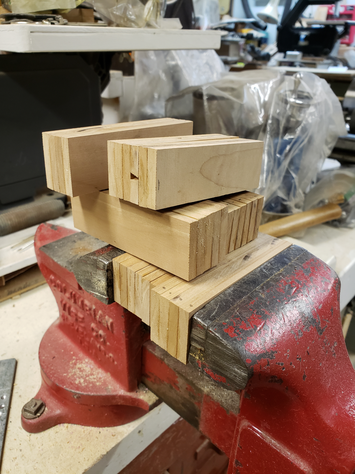
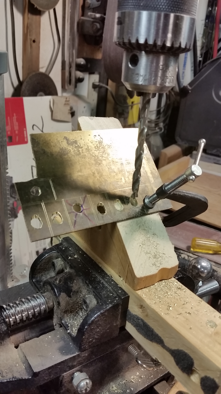
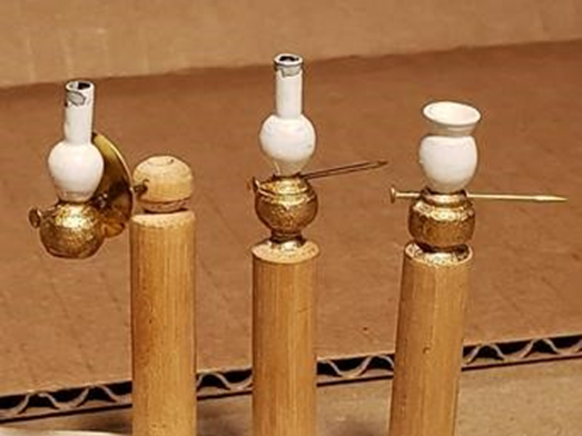
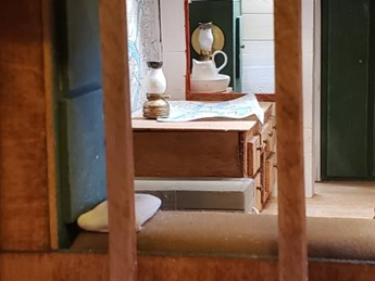
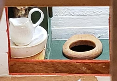
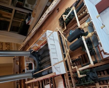
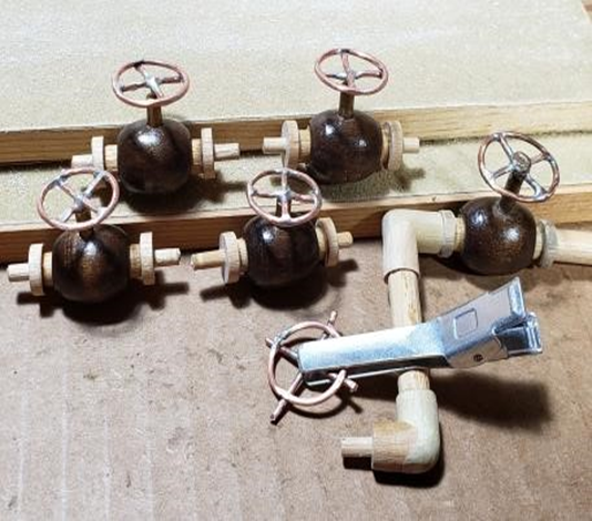
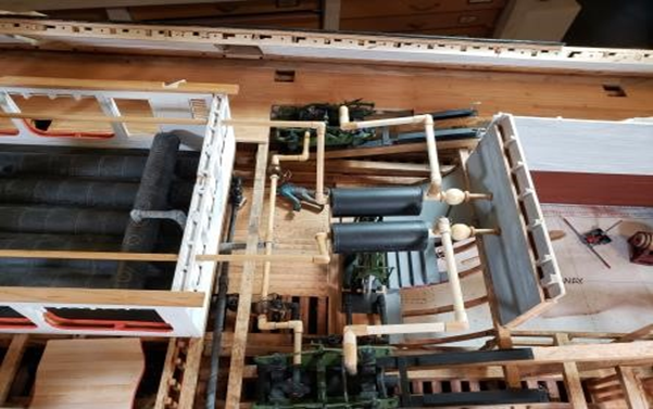
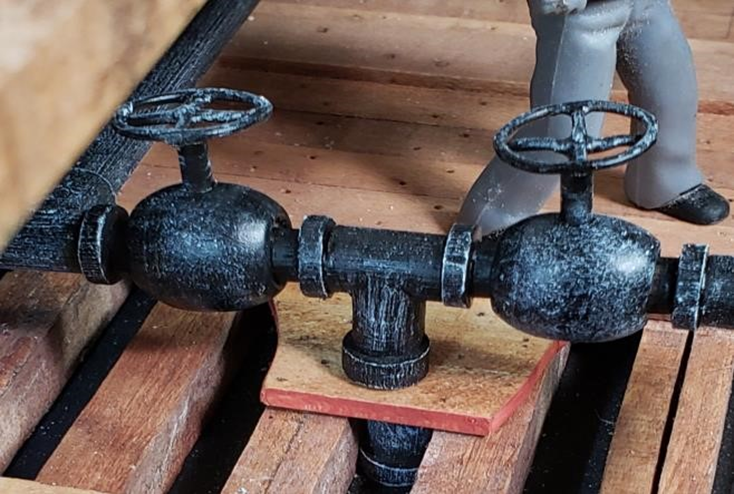
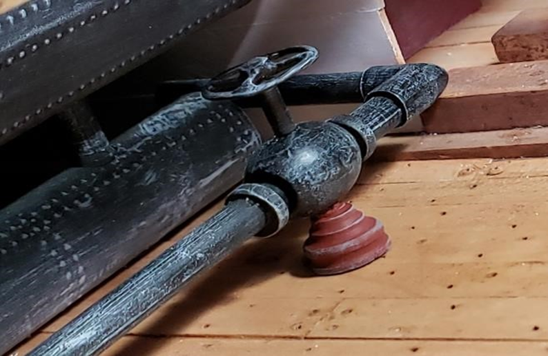
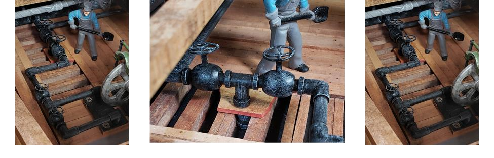
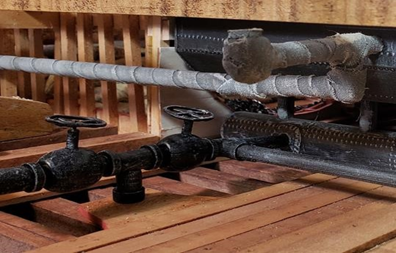
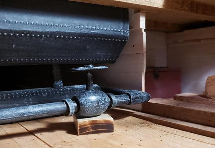
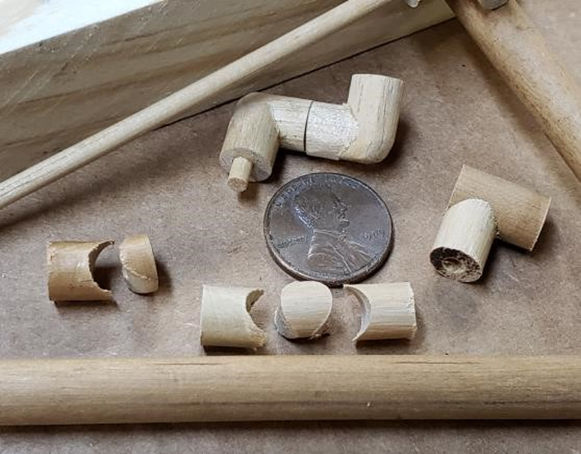
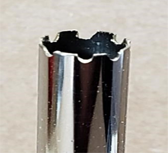
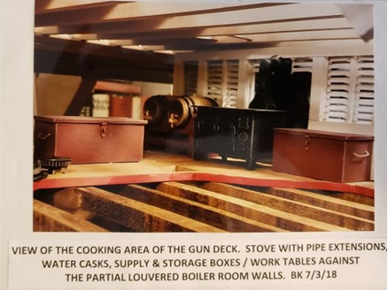
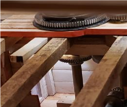
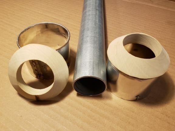
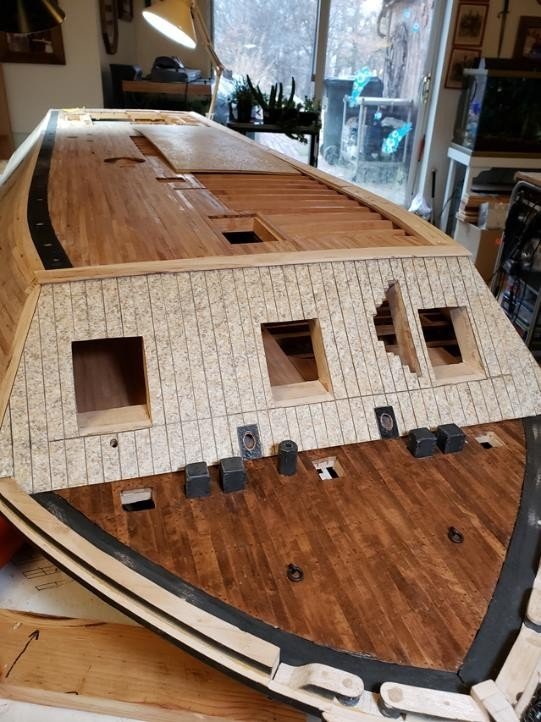
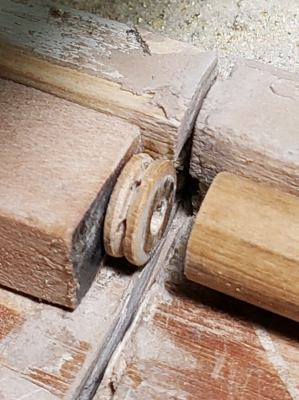
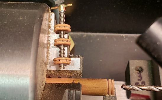
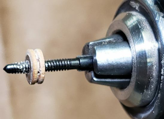
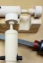
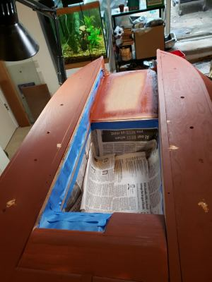
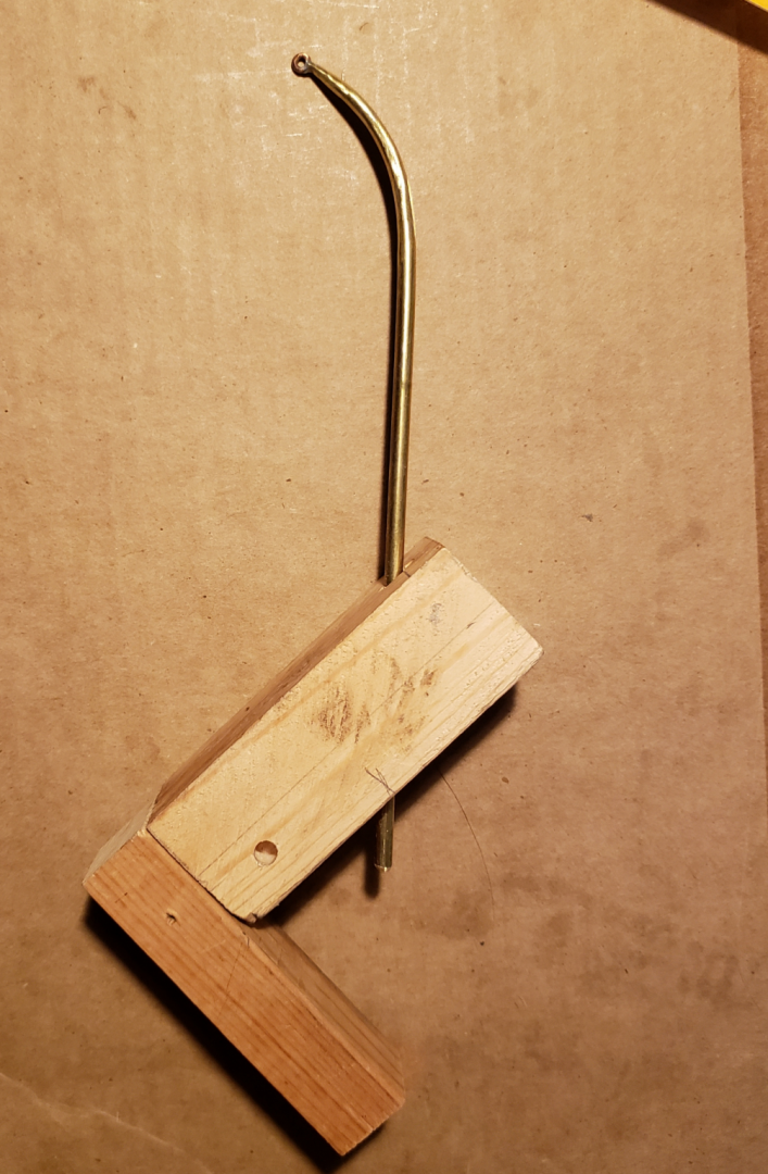
(more March 2020) Illumination in the Captain's Quarters Making water and steam valves in 1/24 scale: 1/4" Macrame Beads, 1/8' and 3/8" dowels, plus 16-gauge copper wire, and you are ready to become a steamfitter! Live steam pipe layout; Steam pipe elbows and T's measured, cut and assembled to form the live steam loop. Portside view of live steam loop. Main river water intake port through the hull. Valves control the direction of the river water in, and cleaning water out of, the system. Turned wooden support for goose pen valve just to add interest and color versus a block of wood. (Left Picture): Main water valves for the boiler and doctor engine: Inflow valves and water pipes to the doctor engine. (Middle Picture): Main in-flow valves and tap between them through the hull for river water. By opening and closing specific valves, this system could also be used to clean out a mud drum as well as the doctor tanks. (Right Picture:): Overview of the river system. Mud drum connection to main water valve and offshoot to water supply for goose pen. Valve to control flow of water to structure under the hot fire boxes (goose pen). Goose pen (loose brick in a tray with water circulation) kept the deck from being scorched by the high heat of the fire boxes. Quarter-inch dowel center drilled and cut in jig to fit at a right angle to a quarter-inch dowel making an elbow or a "T". Simple teeth cut on the end of a quarter-inch (O.D.) brass tube makes an excellent cutter when used with a simple wooden jig. Wooden jig and brass tube cutter cutting dowel. This was a demonstration cut. The real ones were center drilled first on the lathe with an 1/8" bit. Penny for scale. That's all for March 2020. The next entry will be from June or July of 2020. The Club did not meet as such for the next year or so due to COVID. However, Bill Kammermeyer posted photos and captions from work he did on his own. These will be posted in the next entry. Hope you enjoy these. Tim Jovick
-
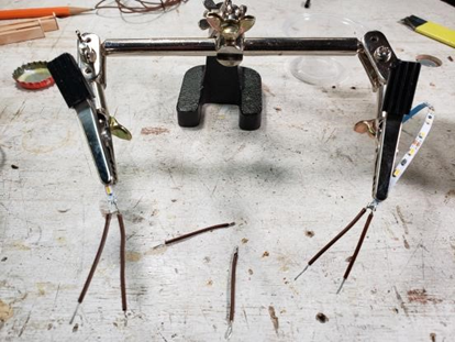
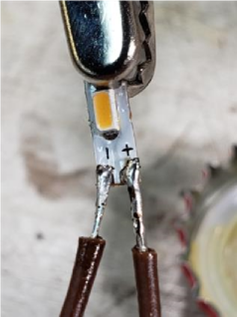
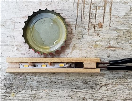
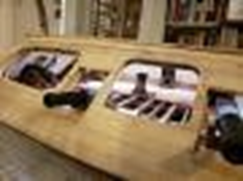
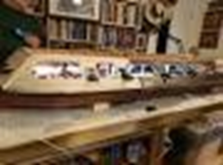
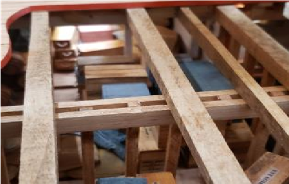
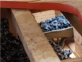
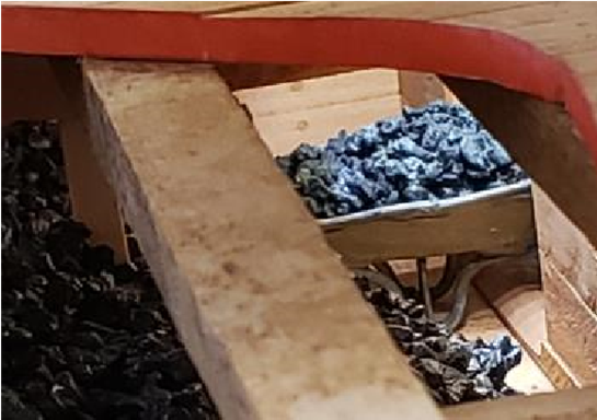
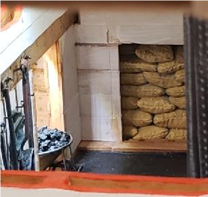
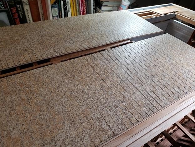
(continuing with March 2020) Making track lighting: Extra hands needed to hold 1/8-inch-wide LED light strips for tiny lead attachment. Detail of tiny lead attachment to 1/1000" thick foil strip on 1/8" wide LED slight strip. LED strip is immobilized in wooden track by glued block at foil contact points and glued 1/16" wood strubs between lights. Block covers heavier wire and protects the thin foil contact points from being torn from the light strip during installation. These 3 shots were just to determine what illumination level that would look best with cannon and propulsion equipment in place. (sorry for the fuzzy images) More light testing, this time in a darkened room. Center line of lights was in three parts. Connecting wires went to the starboard track under the Hurricane Deck planking and then as a common line to the Hurricane Deck terminal. One line went from here to a junction box on the Gun Deck. The long wood channels were screwed to the underside of the Hurricane Deck and then the LED strips were installed with glued wood blocks at the connection points and glued wood stubs between the LEDs. Lighting the forward storage room. Illumination in the steam capstan gear room. Illumination in the bulk coal storage bunker. Illumination of loose coal in wheelbarrow and bagged coal in coal bunkers of boiler room. Posting now so as not to lose the photos. More March 2020 coming below.


-
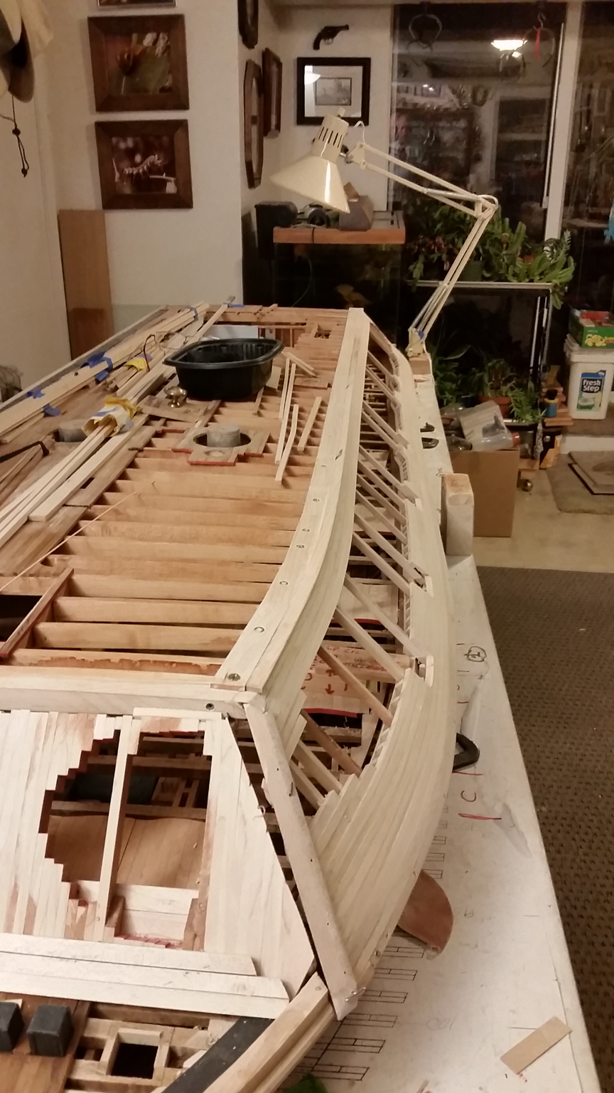
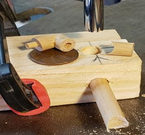
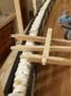
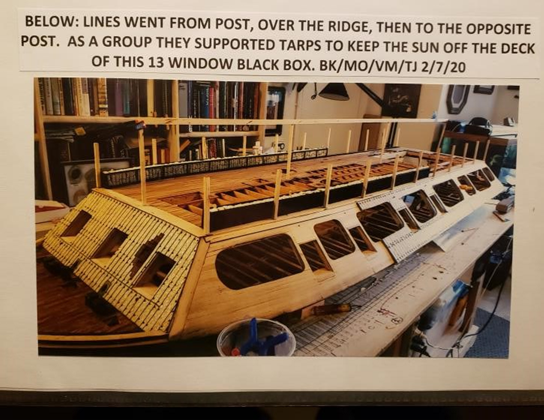
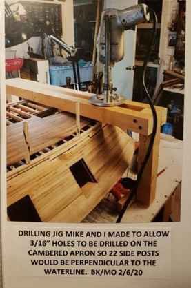
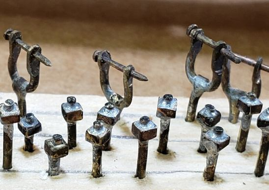
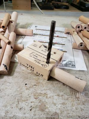
Hi all, Again apologies for my delay in posting entries from the Gateway Ship Crafters for some time. We've made a lot of progress since February of 2020, and indeed we're (maybe) getting close to the end, we'll see. So now we start with March of 2020 As the photos show, much progress has been made in designing and installing the micro-LED track lighting strips to illuminate the interior of the USS St. Louis. Stanchions for a canvas cover and the fashioning of pots and pans for the cook stove are also being planned. Work will also be done on building the launches plus other side projects. (Note that photos and captions are by Bill Kammermeyer) Making posts for a canvas cover on the Hurricane Deck. 3/16" dowels were cut into the ends of the posts for a centered, snug connection for the posts. This was the same procedure that I used for making axles on the axle trees of the cannons
-
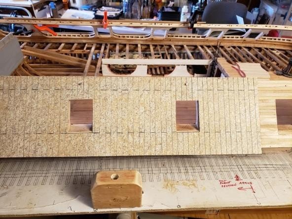
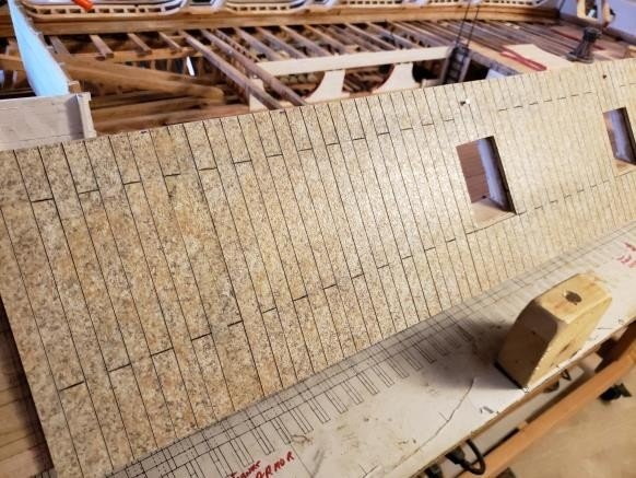
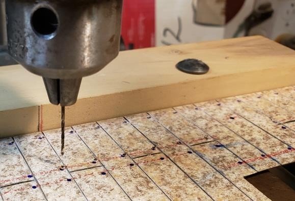
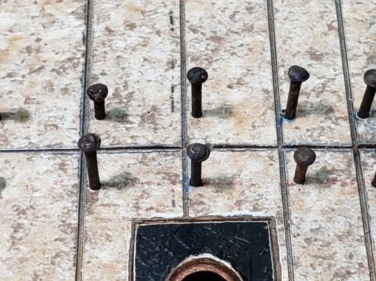
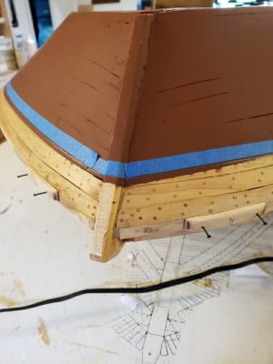
More from February 2020: When painted and dry-brushed, the seams should look quite realistic. Using a jig on the drill press and following pre-made marks as per plan, holes for the armor bolts were drilled. Modified brass pins with a washer and hex head pounded into them were placed in each hole and pushed flush with the surface. The bolts were placed in each hole for the lower band of armor, hammered flush and then cut and sanded flush on the back side. Every 6th bolt was omitted so that a full long nail could be inserted for extra strength after gluing. Mike and I attached Mike made the weather deflectors for the smokestacks that would run rainwater off the top edge of the insulating collars for the Hurricane Deck. They were center board pieces of maple that were then shaped to the plan dimensions by hand. I then enlarged the center hole on a spindle sander for a snug fit on the smokestack pipe. It will attach snugly to the smokestack and have no contact with the heat insulator below it. It will be covered with metal foil and rivets. Hard foam block used with a drill press to make uniform repetitive holes for hinge cups. After drilling center holes in bottoms of cups, holes were drilled for flat head pins which were soldered into place. One end was rounded while still on the brass stock, then they were cut to uniform size using a stop on my Mini- Chop Saw. The heads of the brass pins were tinned with solder and placed in pre-drilled bottom holes and heated with a soldering iron. There was instant attachment. Hanging a clip from the bottom of the nail caused it to drop down flat in the hole as soon as the solder was liquid. Other side of the cup was rounded holding it by the pin in a pin vise. Holes were evenly spaced on the hinge strap. Referencing mark on back of the wooden guide made for even spacing of holes Brass pin joined the strap and the cup with a brass hinge pin cut and peened to finish the assembly. Only 50 more to go! Bow gun port doors Working gun port doors. Making cleats out of 1/8” brass rod, for the ropes to the gun port doors. Sorry for the small size of photo and fuzziness OK, that's all for February of 2020. March 2020 comin' up!

-
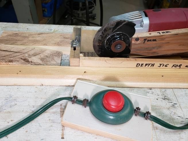
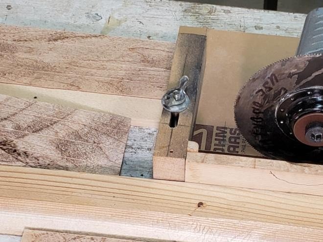
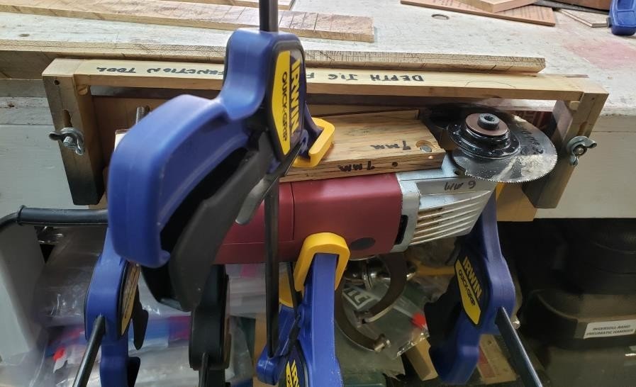
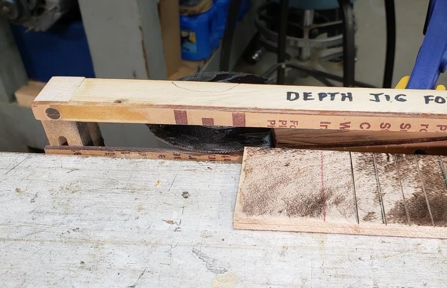
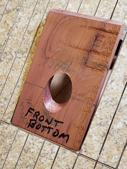
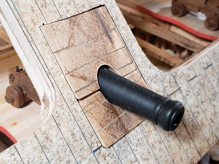
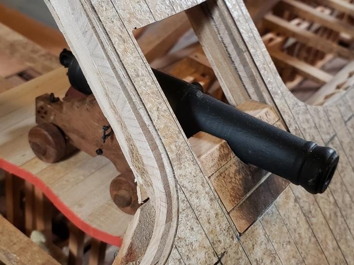
OK, more from February 2020: again, pictures and captions are by Bill Kammermeyer. Outboard horizontal plank scribe lines to be cut for gun port lids. Used a vibrating multi- tool and a Square to scribe the lines. Using a strip holder for the gun port lid stock, vertical inboard scribes were made with the multi-tool and jig. Wood at center was used as a straightedge guide for the jig using the adjustments front and back. Strip at side was a guide for both outside scribe lines. The jig was then used for the center line cut. Use of a foot control on/off switch made cutting the lines much easier and safer. Detail of fine scribe lines in gun port lid stock. Each took about 4 seconds to make and were very accurate with controlled depth. The gun port stock represents a two-layer lid construction. Horizontal planks on the outside and vertical planks on the inside. A differentiation line needed to be run down the center of the quarter-inch stock. The multi-tool in its jig was clamped to the side of the workbench. The lid stock was run along the side of the workbench at the correct height and the line cut into the stock in about 5 seconds. This type of construction was chosen to eliminate the need of laminating individual strips of wood and trying to keep them square and true. Also, there is no worry about delamination 45-degree holes are drilled in the centers for cannon barrels. View of the cutting blade 1/8-inch above the surface of the workbench surface. Center line cut may be seen on the facing edge of the stock. The lids will be pre-cut and the cannon holes drilled individually for the specific height of the cannon caliber. All doors will be painted black so the sugar burn on the Maple will be irrelevant. Gun port doors rough-cut to size from pre- scribed strips. 45 degrees at both top and bottom. Rough cut doors are checked for fit. Mike and I measured and marked the gun port blanks for the 45-degree-angle hole for each cannon. The doors will be cut across at that horizontal center line so cannon may stick out. Practice blank to establish center height for each caliber of cannon. Hole was drilled at 45゚ angle for proper alignment in casement. Actual gun port doors cut and rough fit for each caliber of Cannon. Bottom portion of gunport doors on casement sides will be in a closed position while the top portion will be open and held at a horizontal plus angle. Strap hinges will be added later. Before doors were made stops had to be placed inside each port. A jig (right) Was made to match door thickness and then stops were applied from the inside against the back of the jig. Stops were installed, glued and clamped (left). Using a 4-tooth vibrating blade on the modified on the multi-tool, I was able to cut controlled horizontal seam lines as seen here in a freehand practice session. I set up a straight edge on the seam line and cut every other armor plate in a very controlled fashion using a tool on/off switch. The tool again worked very well, and no extra blade need be purchased. I just ground out a flat spot on the 300-degree “half-moon” blade that left 4 teeth that moved only a few thousandths of an inch per stroke. OK, moe from February 2020 hopefully coming shortly. Please to enjoy. Tim


-
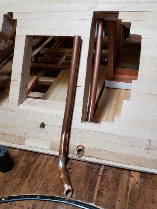
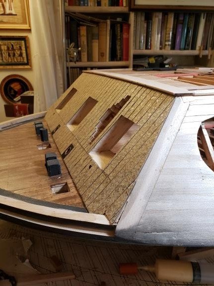
OK, these pictures are from February 2020. Again, apologies for the delay. And thanks to John (Howie) Smith for his clarifications of issues regarding several topics, for example the Doctor Engine and the rudder assembly. Photos and text by Bill Kammermeyer. Stern hurricane deck cap strap in place and view of Scribed sheets of Formica glued to thin plywood to make a scale 2½ inch sheet of armor front casement armor for the side casements Bow casement armor glued in place and cut to fit gun ports and descriptive opening. Long chain pipes to guide steering from the underside of the Hurricane Deck down to the Aft Deck pulley system for the rudders. The Hurricane Deck cap strip cut and glued in place. Both bow Just in from Fred Hecker, nicely gunport hinge straps made from ½ inch wide copper with a and stern deck cap strips had to follow the camber rolled and soldered bottom edge that fits the hinge pin. They will be cut to length and drilled with the Hurricane Deck. A tricky bit of fine work! and snugly fit the casements, yet still be able to be removed for attachment to gun port lids. These are only the first six of many from February of 2020. More to come later. Tim

-
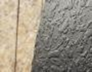
Well, it looks like those photos will work fine. Again, apologies for the graininess, but hopefully the pictures will give the general idea. Still from January, 2020: Armor for front casement cut, fit, glued and clamped in place. Glue was allowed to dry overnight with clamps. With gun ports and cutaway cut and filed to shape. The short side A close-up of the texture of the Formica armor which shows up pieces were added and clamped with tape until the glue is dry. much better when primed and painted flat black. This texture will have The chain pipe holes were cut to shape. a very nice effect on the scored armor plates. 32 pounder cannon implement rack made by Tim that will attach to Parrot Cannon implement rack by Tim. the interior casement walls. 45-degree setup on drill press to drill elliptical holes in armor plate This is how you drill an elliptical hole with a round bit so that that goes around the forward chain pipes. the angles chain pipe fits in a snug fashion. These plates will be cut in a rectangle a bit larger than the chain pipe and fit into a recess in the armor on the casement. OK, that's all fro January 2020. February 2020 coming up soon! Tim Jovick

-
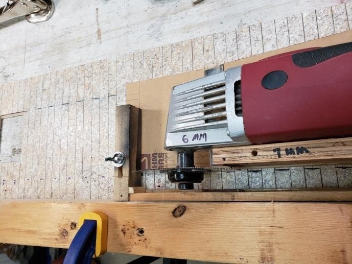
OK, these pictures are from January of 2019. Going to post a couple of them to test if they get saved. Unless otherwise note, pictures and captions are by bill Kammermeyer. Apologies for the graininess of some of these photos. A new and improved method for cutting the armor plates in a Using a hacksaw blade with a knife edge blade in a first cut slot, consistent width and depth using a flush cutting tool mounted in an the adjustable fence allows the next repetitive cut. The elevation screws elevating jig. keep it at just a few thousandths of an inch deep. Fast and accurate!
-
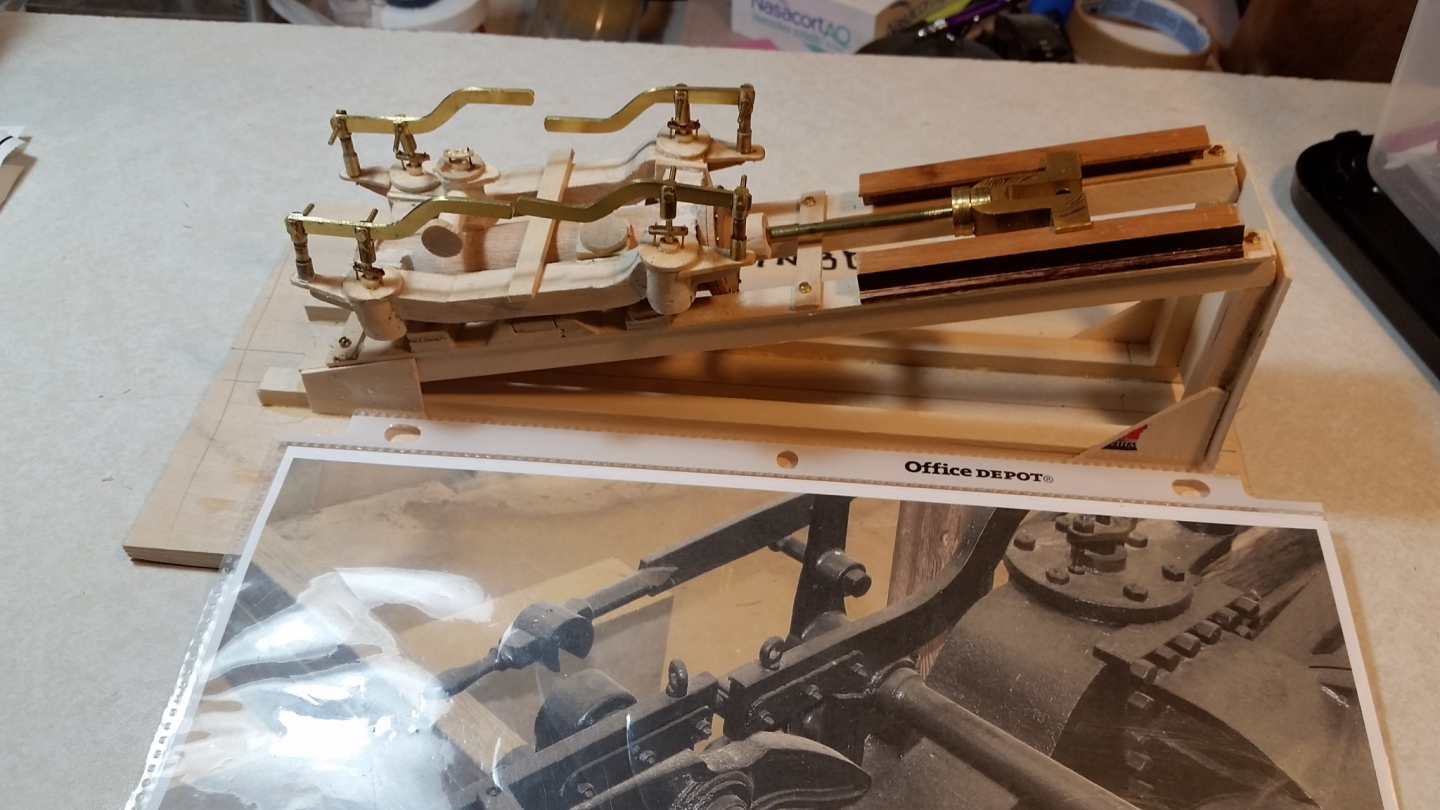
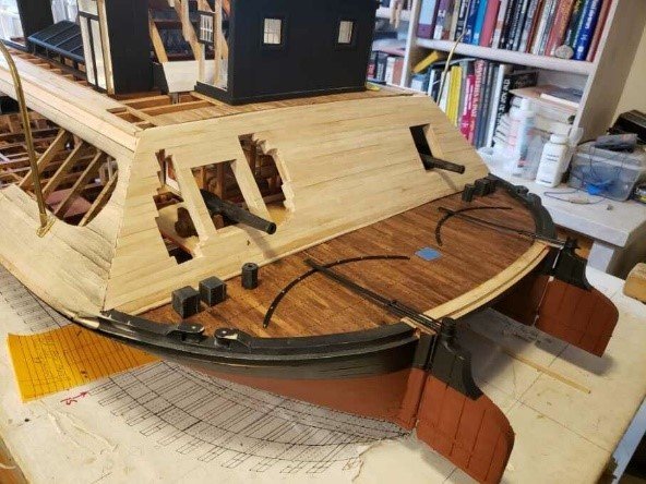
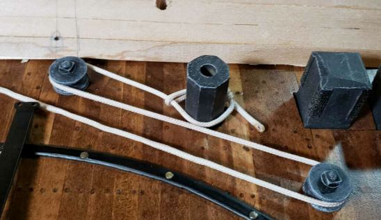
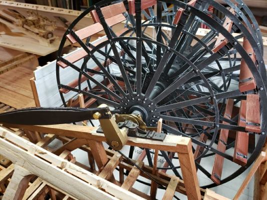
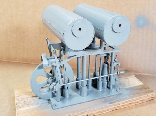
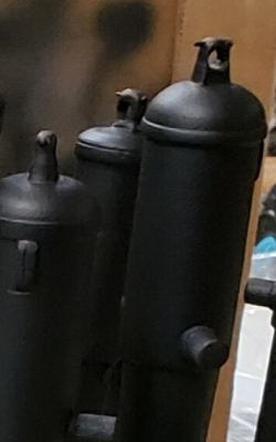
OK, a few more pictures before we go on to the next group. And keep in mind that our progress and meetings were very uneven due to the Pandemic. here we go! Waterline masked befoe painting back portion of the hull. Painted rudders and steering assemblies in place. Parrot rifles on carriages for another test fit. Cord from dot on rear casement (out of picture)to roller to second roller and Detail of cams and drive linkage on the paddle wheel shat. then to tiller. The cord will be chain on the finished model. Dr. Mike Orgel and Bob Keeler work to set up drive rods Steam engine in place with Pitman arm and drive linkage for paddle wheel. and cams off the Pitman arms. Doctor Engine parts soldered together (N.B. Parts and assembly by Doctor Engine and condensing tanks primed with petroleum-based primer. Howie Smith) Doctor Engine painted fat back as a base. Cylinders and pumps will be painted a dark green along with frame as was frequently the custom for steam engines at the time. All right, next installment in a few days. Please to enjoy.
-
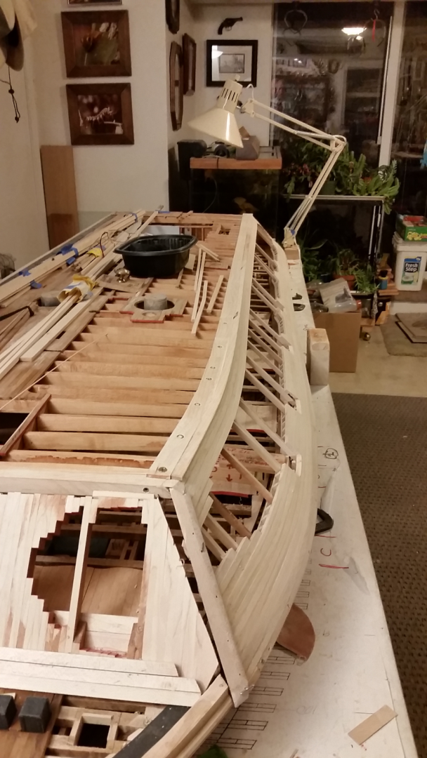
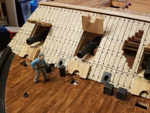
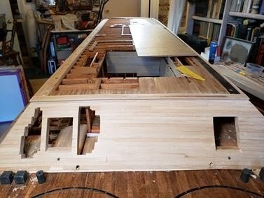
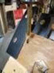
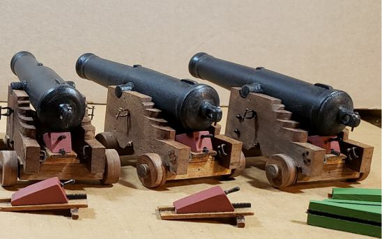
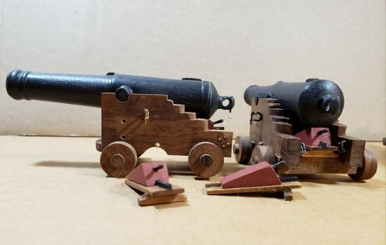
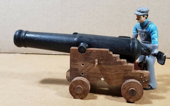
OK, more cannon pictures! Lugs cut to consistent size on my mini chop saw. Turning elevation lugs for 42 pounder and 8" cannon on lathe. Finished lugs to the left of the cutting tool on the lathe. Next time, pictures of rudder mechanism and Doctor Engine! Lugs being tapped with 4/40 threads. The hull is canted to a 45-degree angle with the use of angled supports while the portside ceiling is added around the open sections of the casement. (sorry for the small picture) Breech rope guides, as well as nuts and bolts for carriages. Elevation wedges for 32-pounders. Green wedges for greater suppression Detail of elevation wedges. of muzzle. Scale (1/24) man next to 32-pounder. Cannon in place looking at port side of gunboat. (again apologies for small size of picture and pixillation) Cannons in place looking at starboard side of gunboat. Note racks filled with rolled/folded hammocks on hurricane deck.
-
Got it! Thanks, Stephen, for your guidance in getting rid of unwanted pictures. I'm sure I'll use it many times over.
-
Again apologies for the "three sizes of picture" of the cannon barrels. Somehow can't get rid of 'em. We'll do better next time.
-
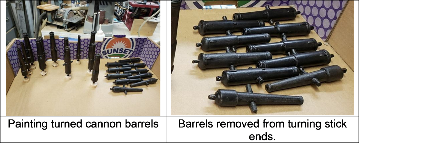
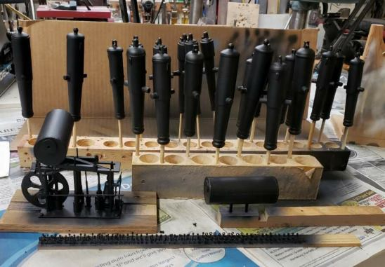
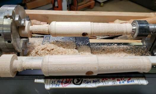
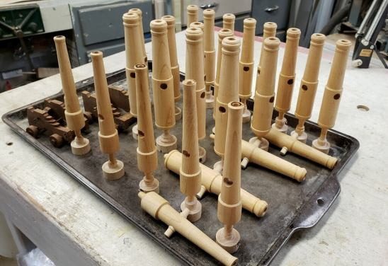
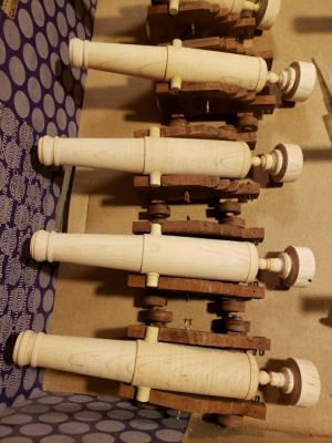
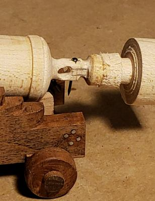
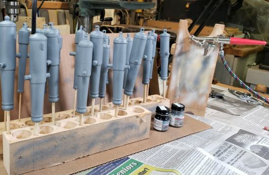
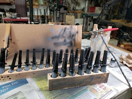
Again from April 2019, making cannons. Pictures and captions by Bill Kammermeyer Trunnion Drilling Jig "Slugs" on lathe with pattern below it that was under the barrel exactly in line with the end of the pattern. Rough plugcuts are ade to pattern limits and then removed to get a smoother surface. Same, closer to the final contour. After cannons are turned, they are given a coat of varnish and sanded again on the lathe. Here, they are drying with ends still attached. 42-pounders showing what a great job a duplicator A test fit in the custom-made carriages for each type of cannon. The 32-pounders can do, with a little practice. Here with trunnions needed to have inside-of-trunnion area of the carriage reduced for a proper fit. inserted and laying in carriages. All the trunnions for all the sizes of cannons are the same size, which makes for a lot less work. Hole for breech rope drilled in cascabel with hole for removable Detail of the flat taper of the cascabel, before and after. Untapered plug so breech rope can easily slide into the hole for the back. cascabel on jig, coarse file used for tapering below. All cannons are primed with petroleum-based primer using dowels to Primed cannons are handheld to paint the distal end of the barrel let them dry without marks. and the bore and then placed in large holes to dry upright. When the barrels were dry, dowels were used to flip and hold them Detail of painted finish on cannons. It's hard to believe that while the breech end was air-brushed with acrylic flat black paint. this is turned wood and not cast metal. I was pleased with A wonderful finish was produced. the end result. OK, that's all for now. Apologies for inconsistencies in picture sizes and some fuzziness. Still learning this stuff. More on cannons and carriages, placement on the boat, and the doctor Engine next time. Tim


-
O, here we go! These are from November of 2019. Unless otherwise indicated, photos and captions are by Bill Kammermeyer. Covering the underside of the waterway The open and closed portions of the Waterway finished waterway masked for painting Hull on 45-degree angle lift to facilitate easier access by Tim and Vince in Final fitting aft casement painting the ceiling inside the walls of the sides. Final fitting forward casement OK, I'm going to post these pictures to see if they come through. Next series is of making the cannon barrels and trunnions. Back soon. Tim
-
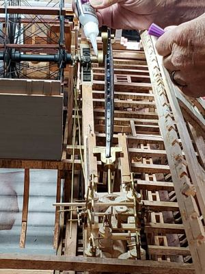
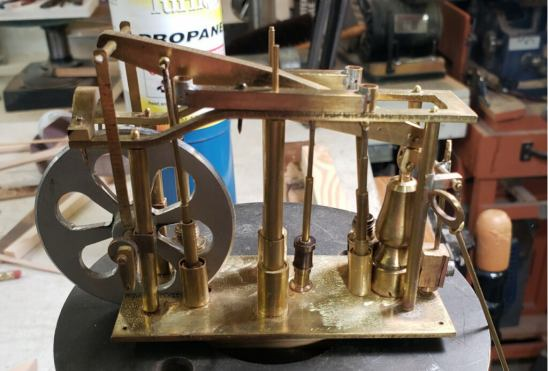
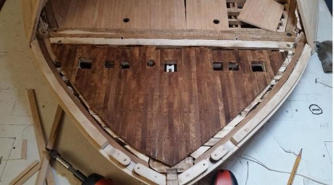
Hi all, and many apologies for this two-year delay in posting pictures from the Gateway Shipcrafters' USS St. Louis 1/24 scale model for the Missouri Civil War Museum. I have had considerable difficulty downloading pictures from the Newsletters, and the attempts to copy and paste from the Newsletters themselves have been fruitless. This difficulty will not be present for the more recent ones, as I have pictures from the Newsletters already downloaded. SO, hopefully these pictures will work. I am going to only post a few, as sort of a test, along with captions. These are from April of 2019. If this works, expect a flood of 'em over the next month or so. Please let me know if there is any problem viewing these pictures. And by the way, my current email is timboni7263@att.net. My phone number is 314-761-5435. Please feel free to contact me anytime. Here we go! Tim Jovick These are some random photos of the building of the cutters, using the bread-and-butter method, plus decking and one of the engines.. Photos and captions are by Bill Kammermeyer. Bread and butter layup for cutter mold. Just sand and file the high spots down to the low spots and you have a hull. Bow deck fully planked and trunneled Steam engines with valve lifters in place

-
All right, here's all the pictures and captions duly redone from above. Grrrrr..... The way the jig was used to drill a 3/16 inch hole equidistant from the edge of the casement at all Davit points. A 3/16 inch long drill bit used in place of the brass rod. (BK05/24/19) With the use of the jig, the stanchions were able to be aligned perfectly. (BK 05/24/19) All four and a half surfaces of deck houses are finished to add visual appeal to the model. (BK 05/24/19) Hammocks (160) are tied and ready to be fitted into the line of hammock stanchions on the hurricane deck (done by Vince and Tim, 05/10/19) Using a 1-in. belt sander, the front casement portholes are rough sanded off the ship. (BK 10/10/19) The horizontal timbers are all fit in place and the port and starboard gun ports are filed smooth and true to the template gauge. (Previous two pictures) Pear slabs are end glued to begin remaking the gun carriages. (BK 05/30/19) Front of carriage locks are trimmed to plan dimensions. (BK 05/30/19) When glue which joined the stacks of cannon carriage sides is removed at plan lines, the stack of gun carriage sides falls apart. (BK 05/30/19) OK, hopefully this will be good. Again sorry for the clunkiness, working to get better. October coming next.


-
()*%T&)(^#$+#@&(_*!^&!!! Did it wrong again, will duly download and copy/paste appropriate pictures. May take a day or so. Sorry folks, 'twill be done!
-
Hi all, finally getting around to posting the remaining pictures from the June 2019 Newsletter from the St. Louis Shipcrafters on the USS St. Louis. Sorry for the delay, and here we go! The way the jig was used to drill a 3/16 inch hole equidistant from the edge of the casement at all Davit points. A 3/16 inch long drill bit used in place of the brass rod. (BK05/24/19) .With the use of the jig, the stanchions were able to be aligned perfectly. (BK 05/24/19) All four and a half surfaces of deck houses are finished to add visual appeal to the model. (BK 05/24/19) Using a 1-in. belt sander, the front casement portholes are rough sanded off the ship. (BK 10/10/19) The horizontal timbers are all fit in place and the port and starboard gun ports are filed smooth and true to the template gauge. (BK 10/10/19) (Previous two pictures) Pear slabs are end glued to begin remaking the gun carriages. (BK 05/30/19) Front of carriage locks are trimmed to plan dimensions. (BK 05/30/19) When glue which joined the stacks of cannon carriage sides is removed at plan lines, the stack of gun carriage sides falls apart. (BK 05/30/19) OK, that's all for now. The next Newsletter was not done until October of 2019, and those pictures and captions will (well, hopefully should) be coming soon. Any questions, feel free to contact me anytime. Tim
-
Hi Brian,
I got your feedback on my most recent posting from June, 2019 (remainder of that should be posted today). I copied the text and forwarded it to Bill Kammermeyer, who's heading up this project. Bill would be able to respond to most of your questions. However, I don't have your email to provide to him, but you're welcome to send it to me (timboni@juno.com) or Bill (bkammermeyer@att.net), so Bill can get a response to you. Please feel free to contact me (314-761-5435) if you have any questions.
Tim Jovick
-
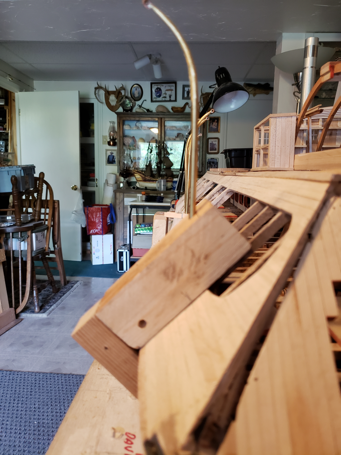
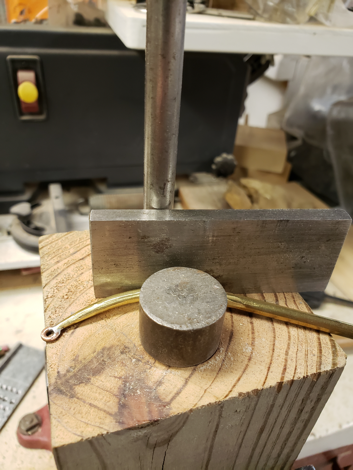
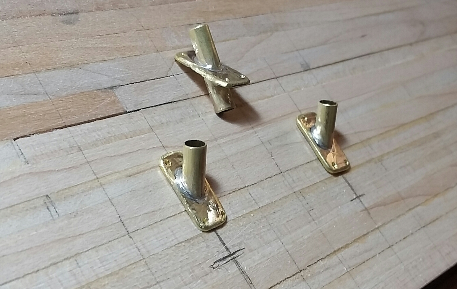
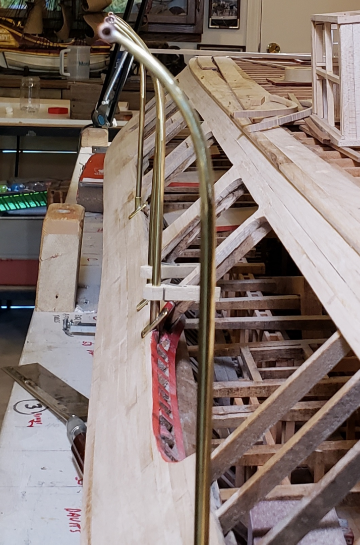
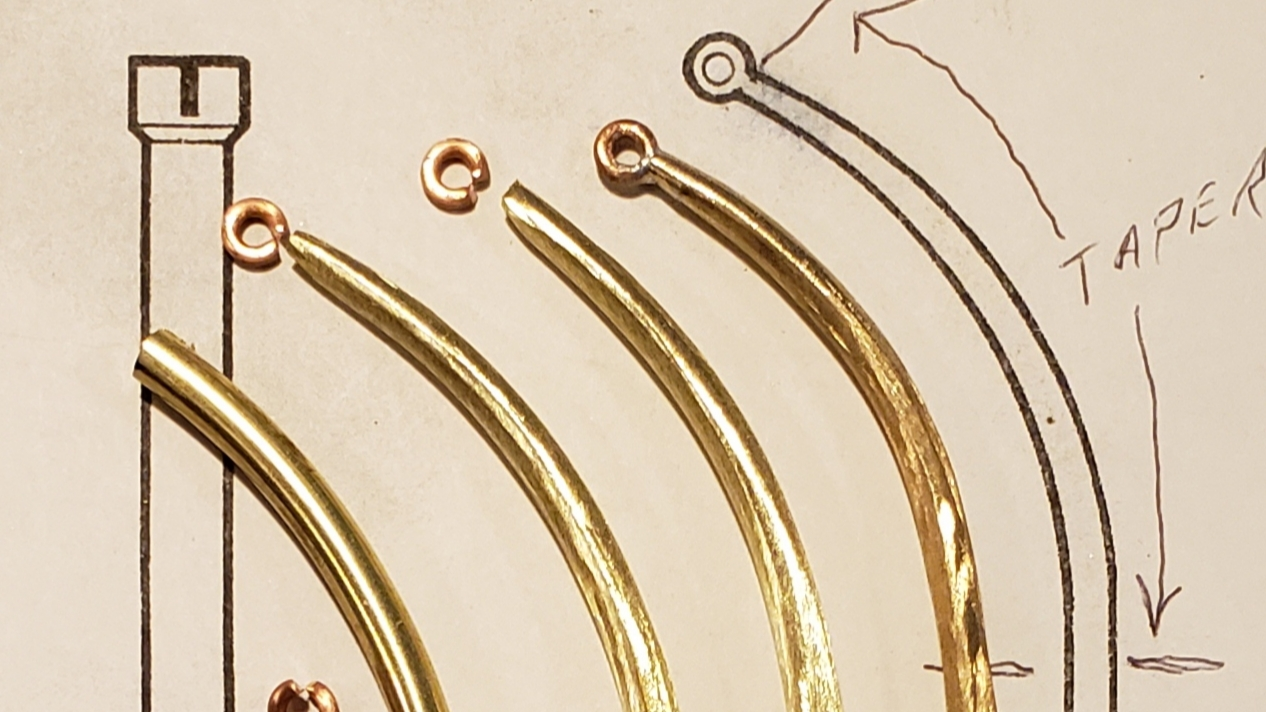
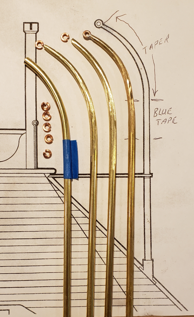
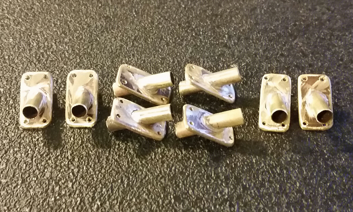
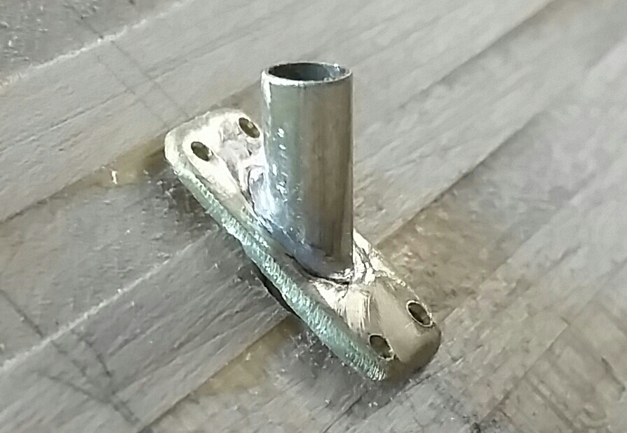
Hi again all, and thanks for your patience. I'll be posting pictures and captions (most if not all by Bill Kammermeyer, noted by BK in the captions) from the June 2019 Gateway Shipcrafters. And here we go! 1/8” brass plate drilled with 3/16” holes to be re-drilled to 45 degrees later. Lower plate was an idea that did not work. (BK 05/06/19) Jig to redrill the holes at 45 degrees on my drill press (BK 05/06/19) Jig used to form the bend in the 3/16 brass rod before tapering or the attachment of the end ring. (BK 05/24/19) Jig used to drill 45 degree angle holes in the casement service to produce an angle perpendicular to the waterline at a constant distance from the edge. (BK 05/23/19) 3/32 inch brass rod was bent and tapered at the ends as per the plans and rings were added to slots in the ends. (BK 05/22/19) Detail of taper process. Sides are sanded on belt Sander to match taper then top and bottom are likewise sanded. edges are rounded and fared into a taper. (BK 05/22/19) Eight 45-degree stanchion supports for the davits have been soldered at the proper angle. (BK 05/21/19) The stanchion as it appears in the pre-drilled hole on the casement. (BK 05/21/19) The pre-drilled holes and the angled soldering of the stanchion sockets made for a very realistic result. (BK 05/21/19) More from June 2019 coming in the next couple of days. Hope these are enjoyable and helpful.


-
Thanks, James. It worked! Now just awaiting some more photos and we'll be off to the races - again! Thanks again for everybody's help and support.
-
Well, well, well! Looks like my copying and pasting the original picture from the email ends up as a link, but the download works! Have now finished loading pictures and captions from May 2019. Many more to come! Thank you for your guidance and patience. Any comment from your end?
-
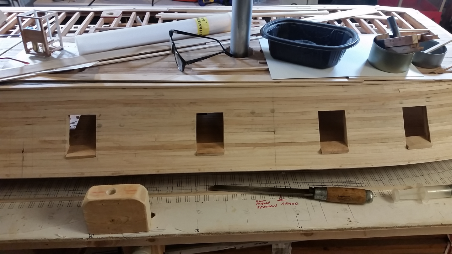
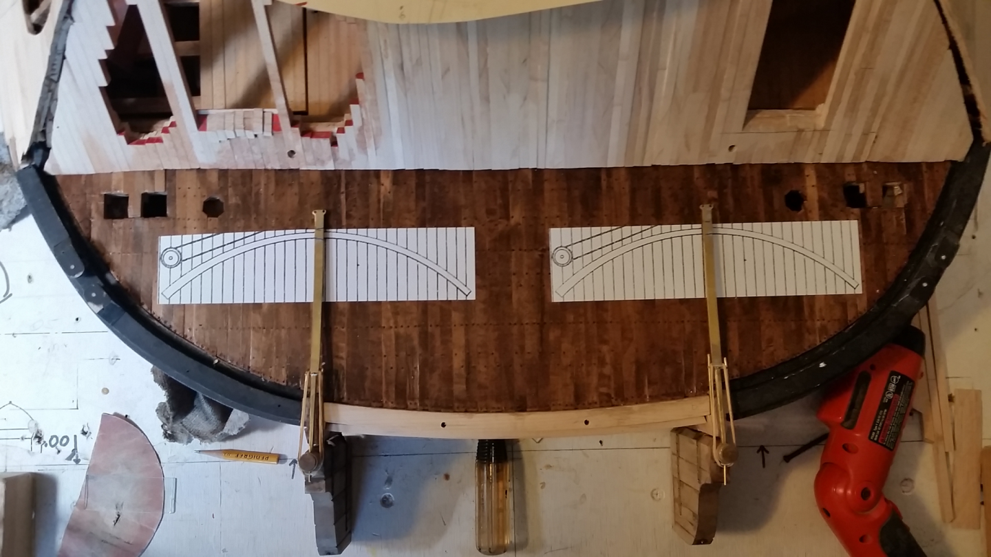
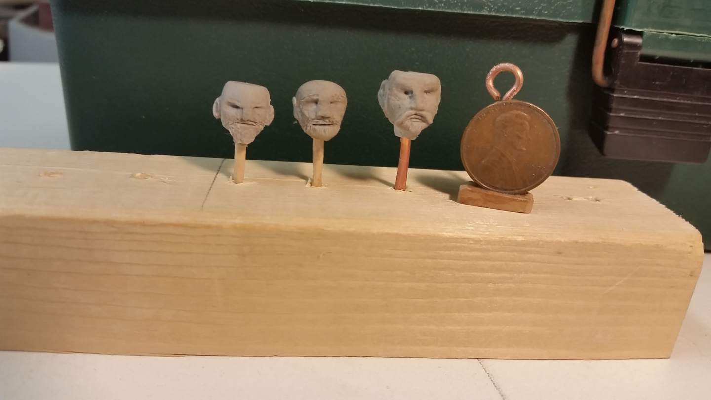
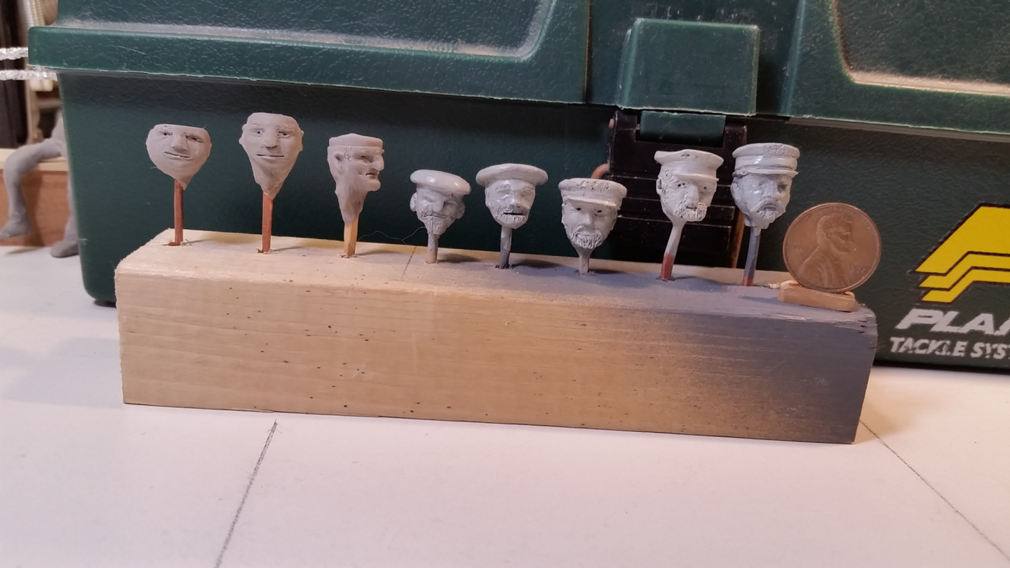
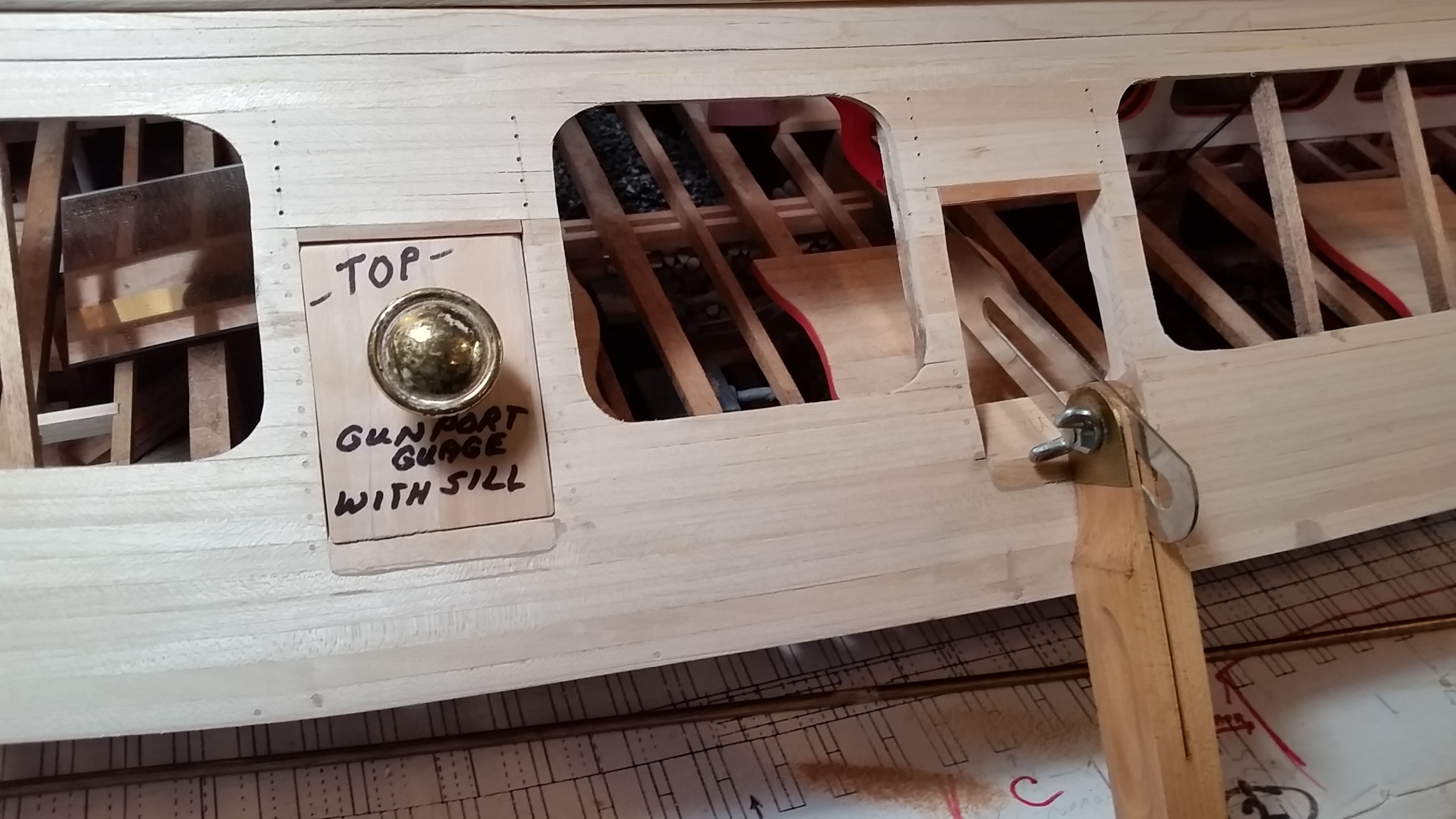
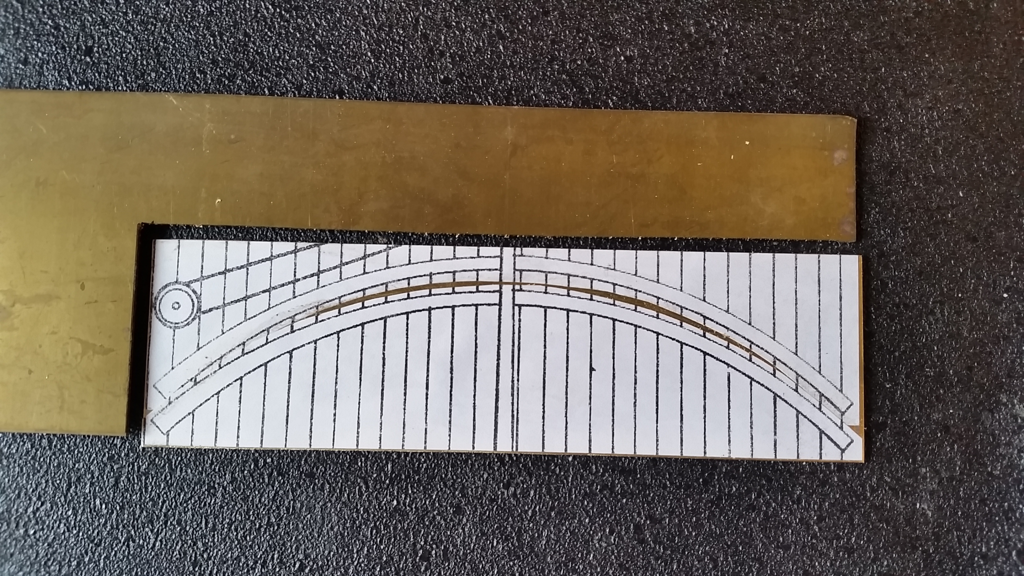
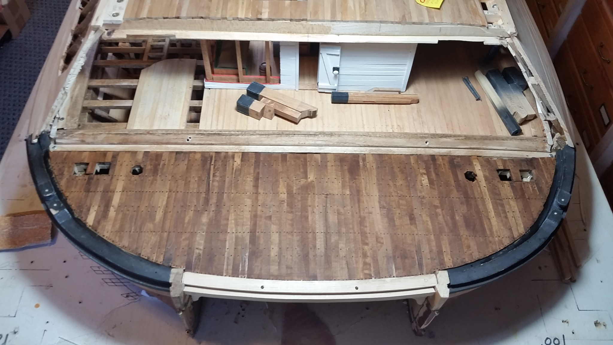
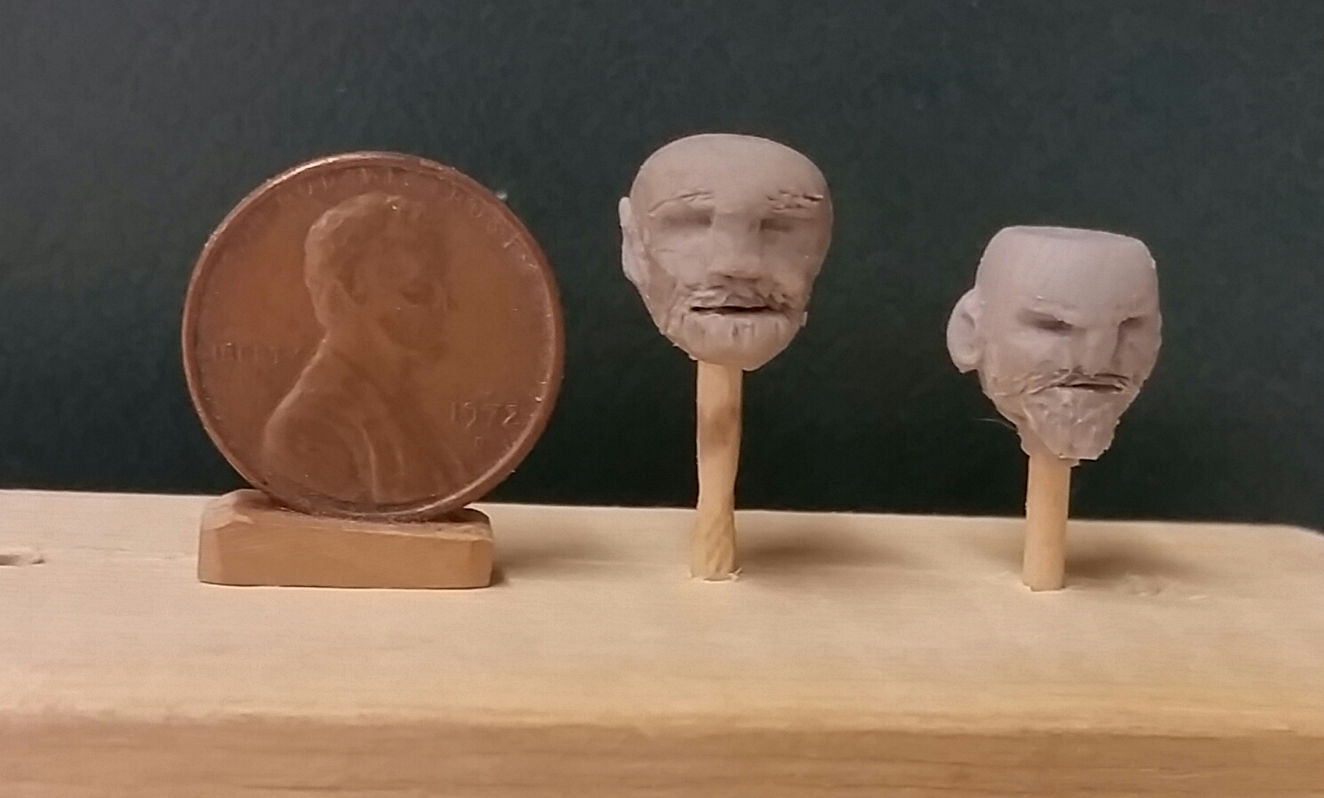
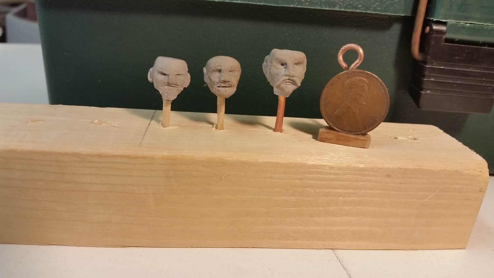
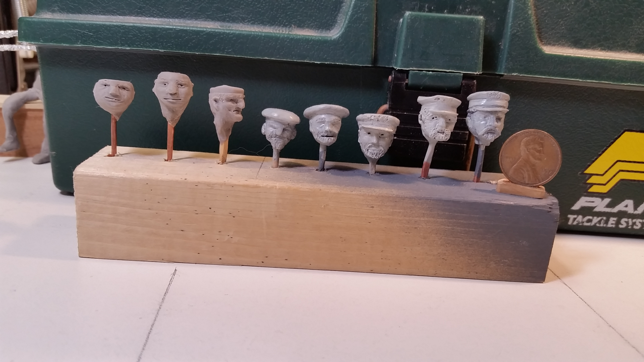
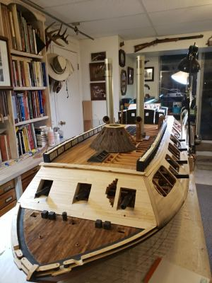
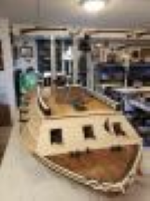
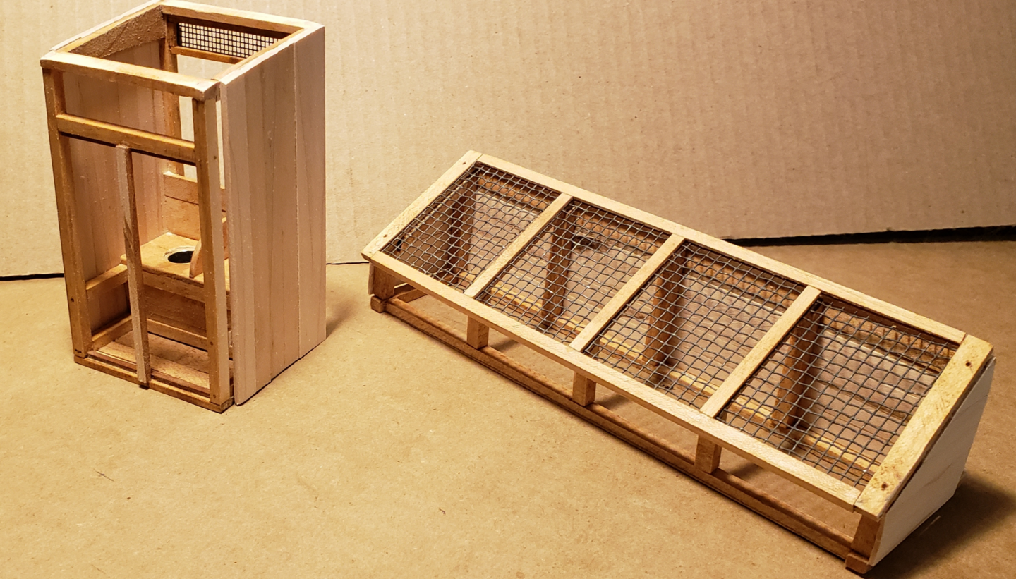
A few more from May, 2019. Again, pictures and captions by Bill Kammermeyer. Uniform gun-port openings with sills installed. Time consuming task to make sure the gun-port sills were 45 degrees to the casement and that the gauge still fit flush. Lay-out of tiller rollers on plans for the "iron" arcs that will protect the deck. After adjusting the tiller "hinges" and rechecking deck layout it was found that the full arc could be used. 1/16" brass sheet with both arcs glued to it with rubber cement. The concave bottom will be cut and filed to the line first, then the convex top. This order gives me more grasping material. The 2 center cuts are easy but filing the edges is more difficult with less material to grasp. Rear deck finished. Crew and Officer heads, with and without hats. Steam engines with valve lifters in place. Bread and butter layup for cutter mold. Just sand and file the high spots down to the low spots and you have a hull. Plank on Hurricane Deck header that will cover attachments off deck to casement and be a base for the hammock racks. View of port side showing improved interior viewing modifications. OK, next entries will be from June of 2019.