timboni
-
Posts
57 -
Joined
-
Last visited
1 Follower

Recent Profile Visitors
632 profile views


-
 berhard reacted to a post in a topic:
USS ST LOUIS by thorn21g - 1:24 - POF - Civil War Ironclad - Gateway Model Shipcrafter's Guild
berhard reacted to a post in a topic:
USS ST LOUIS by thorn21g - 1:24 - POF - Civil War Ironclad - Gateway Model Shipcrafter's Guild
-
 KeithAug reacted to a post in a topic:
USS ST LOUIS by thorn21g - 1:24 - POF - Civil War Ironclad - Gateway Model Shipcrafter's Guild
KeithAug reacted to a post in a topic:
USS ST LOUIS by thorn21g - 1:24 - POF - Civil War Ironclad - Gateway Model Shipcrafter's Guild
-
KeithAug reacted to a post in a topic:
USS ST LOUIS by thorn21g - 1:24 - POF - Civil War Ironclad - Gateway Model Shipcrafter's Guild
-
MAGIC's Craig reacted to a post in a topic:
USS ST LOUIS by thorn21g - 1:24 - POF - Civil War Ironclad - Gateway Model Shipcrafter's Guild
-
mtaylor reacted to a post in a topic:
USS ST LOUIS by thorn21g - 1:24 - POF - Civil War Ironclad - Gateway Model Shipcrafter's Guild
-
Canute reacted to a post in a topic:
USS ST LOUIS by thorn21g - 1:24 - POF - Civil War Ironclad - Gateway Model Shipcrafter's Guild
-
Cathead reacted to a post in a topic:
USS ST LOUIS by thorn21g - 1:24 - POF - Civil War Ironclad - Gateway Model Shipcrafter's Guild
-
Nunnehi (Don) reacted to a post in a topic:
USS ST LOUIS by thorn21g - 1:24 - POF - Civil War Ironclad - Gateway Model Shipcrafter's Guild
-
Ryland Craze reacted to a post in a topic:
USS ST LOUIS by thorn21g - 1:24 - POF - Civil War Ironclad - Gateway Model Shipcrafter's Guild
-
GrandpaPhil reacted to a post in a topic:
USS ST LOUIS by thorn21g - 1:24 - POF - Civil War Ironclad - Gateway Model Shipcrafter's Guild
-
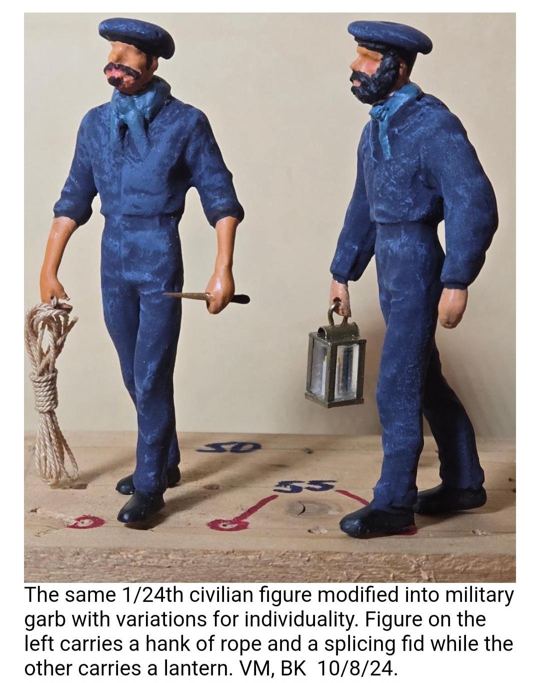
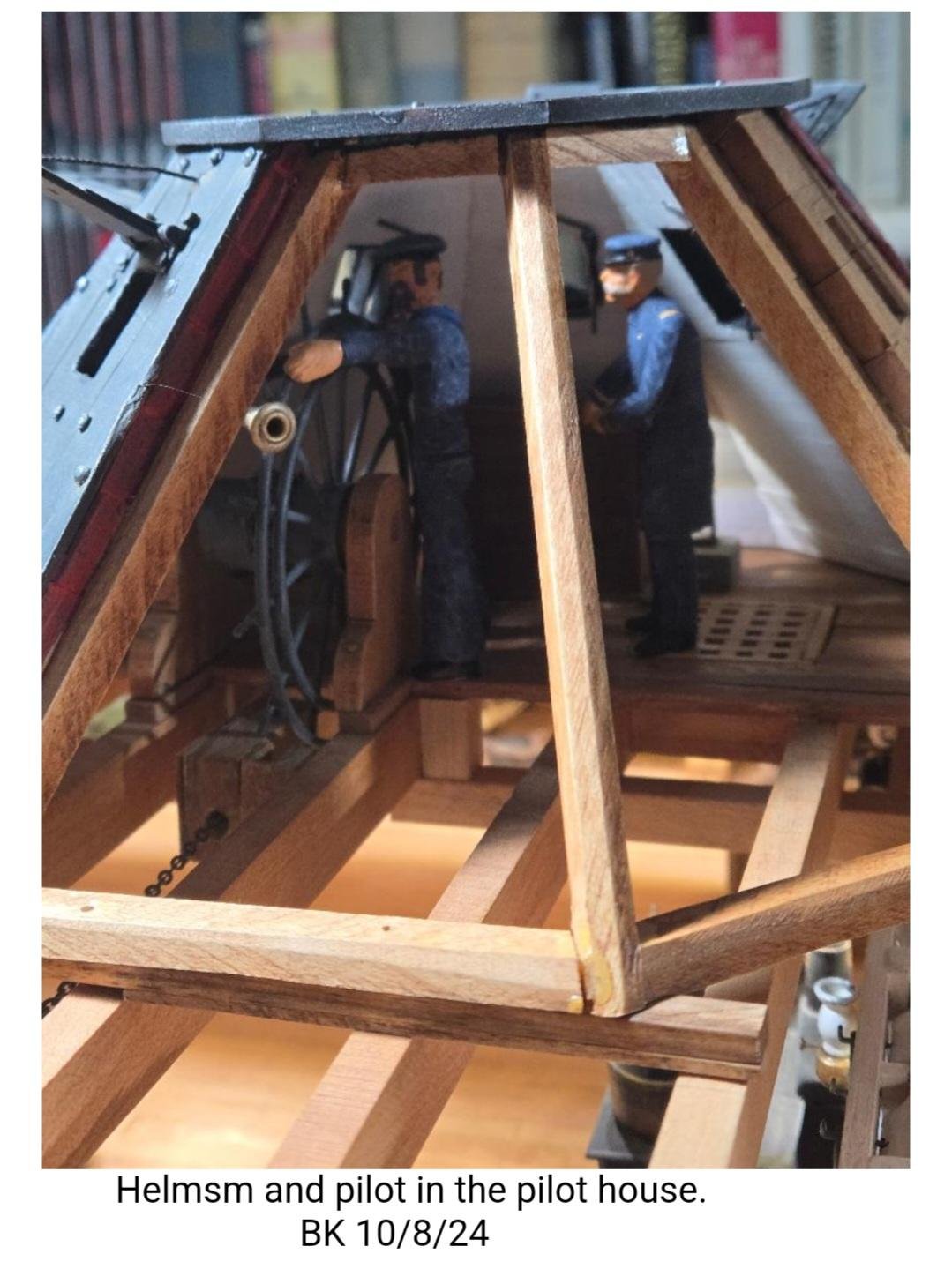
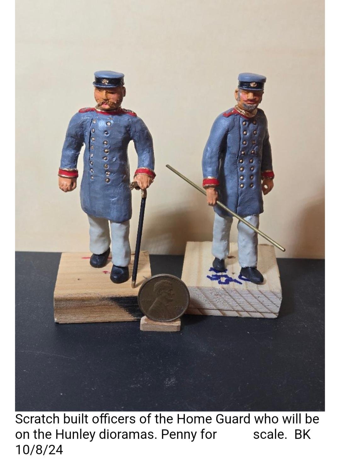
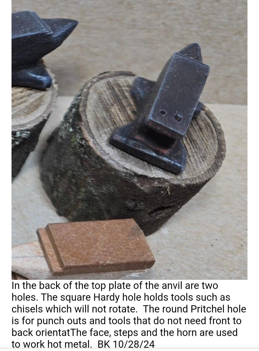
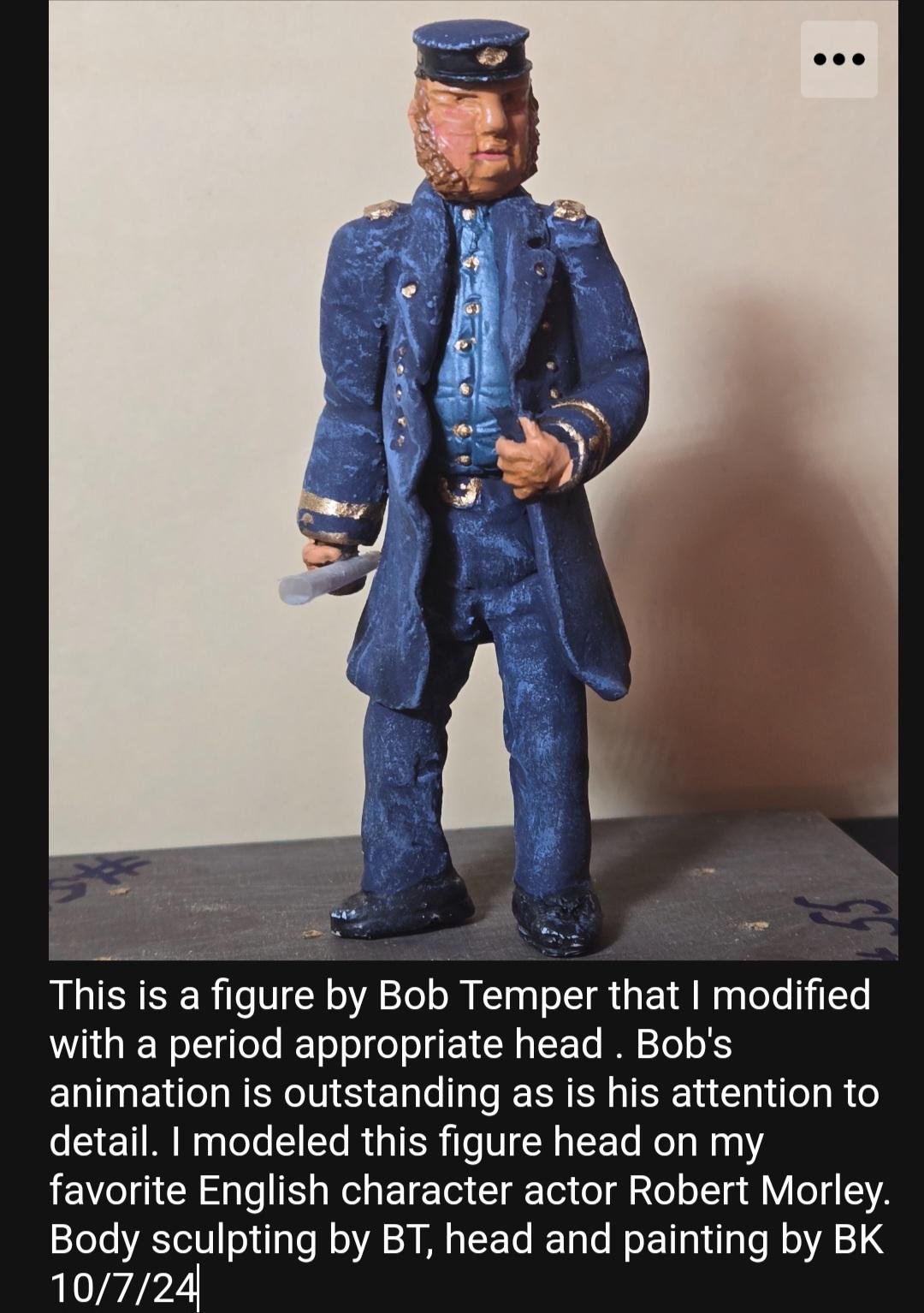
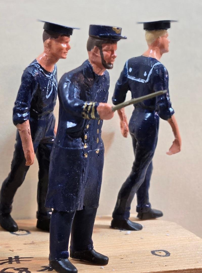
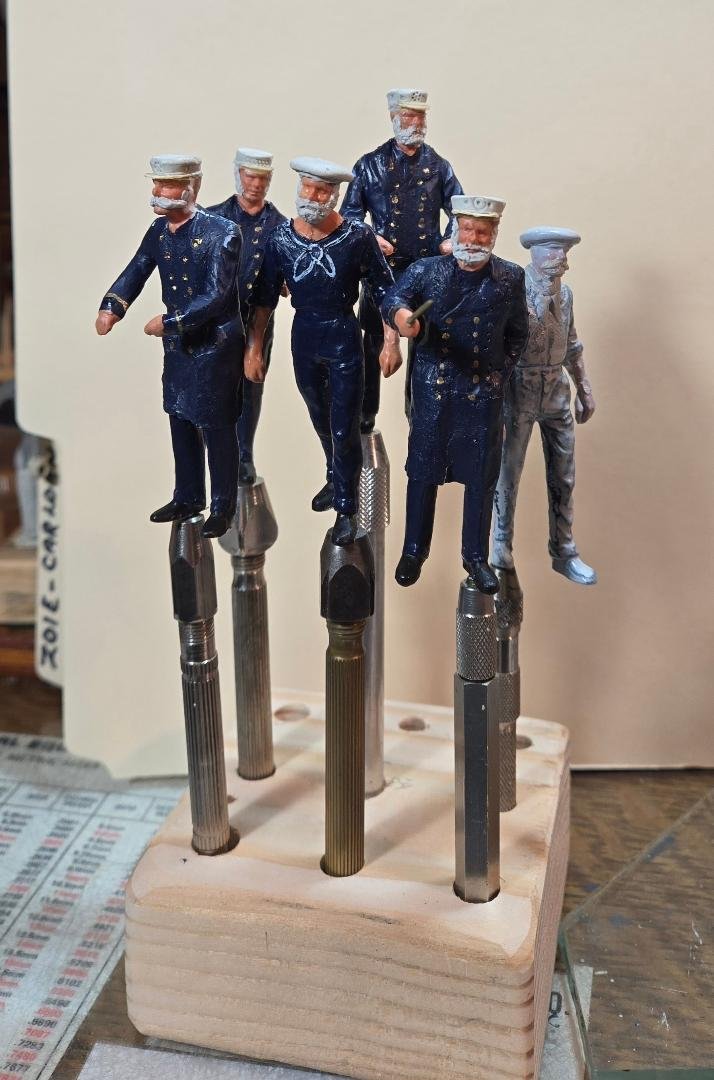
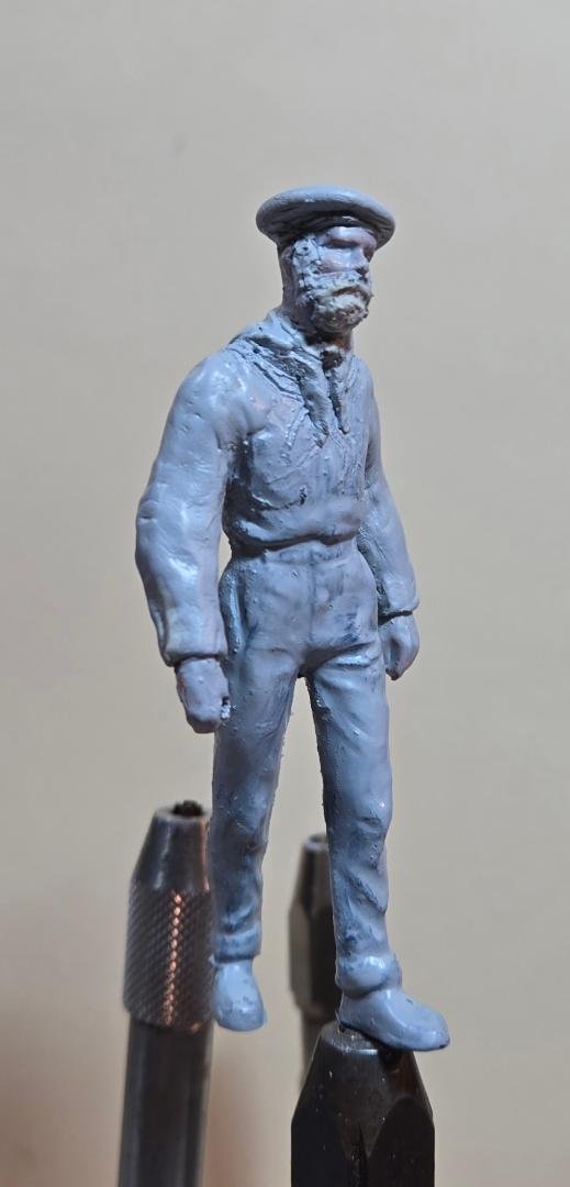
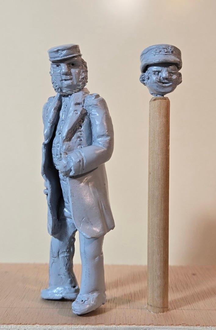
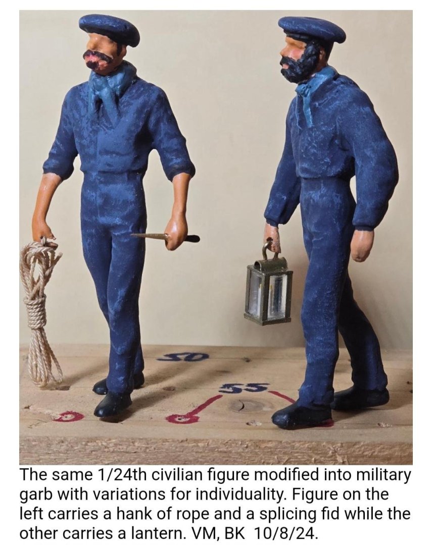
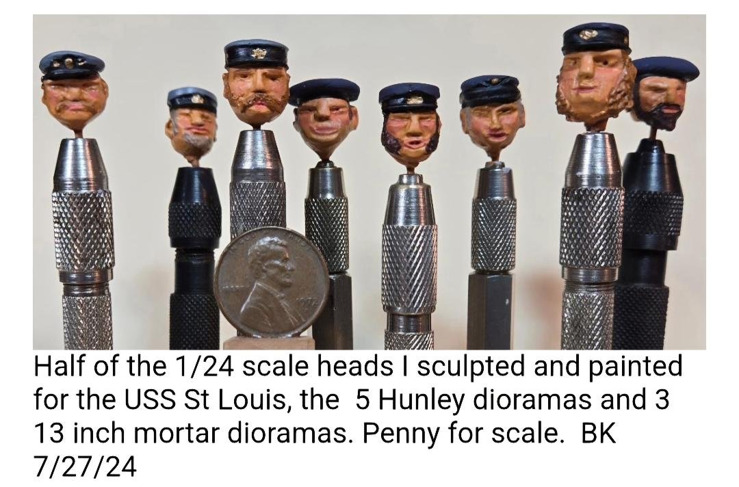
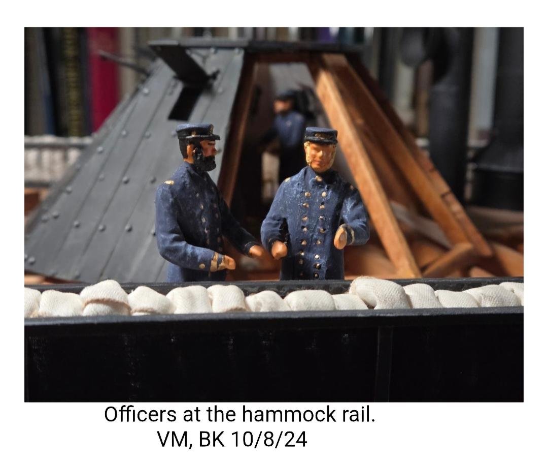
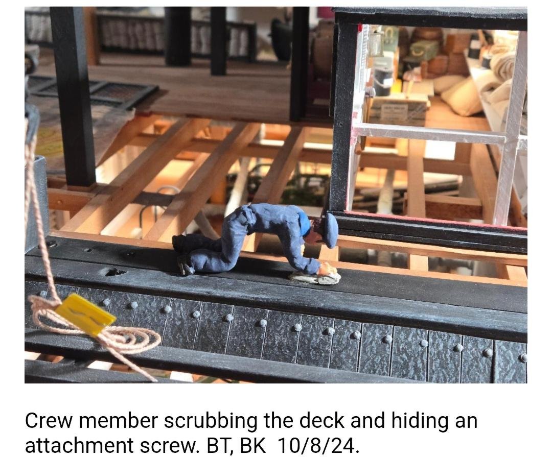
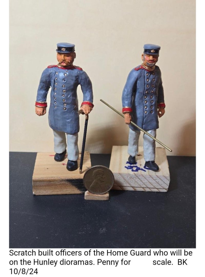
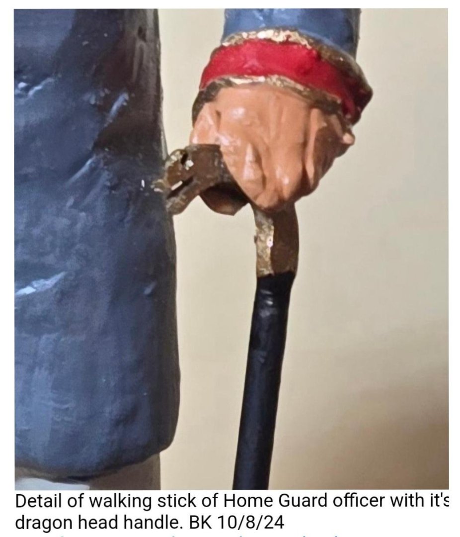
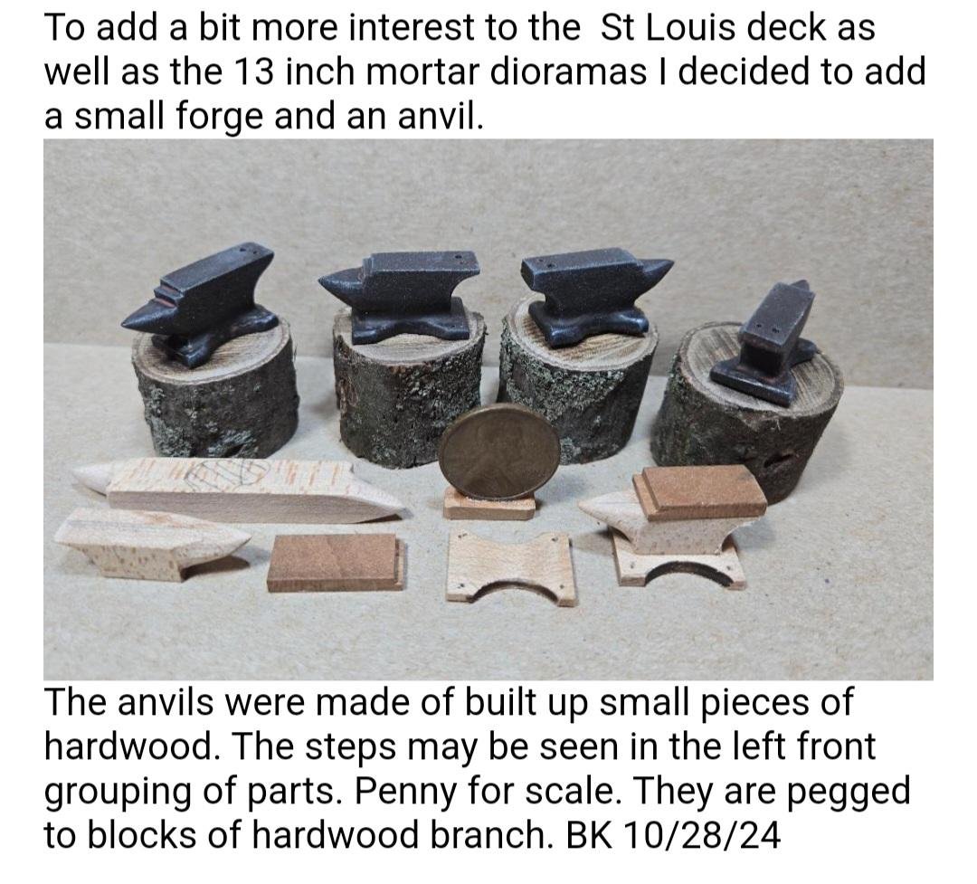
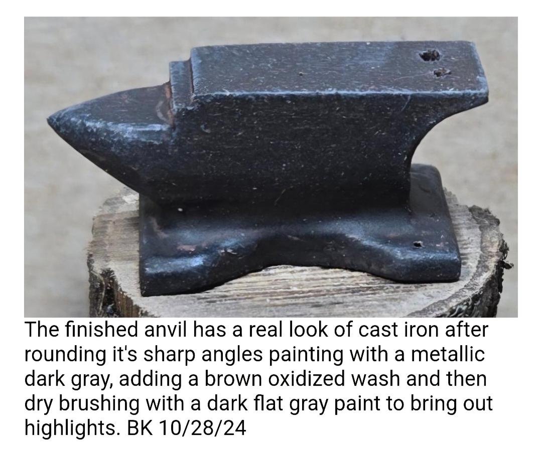
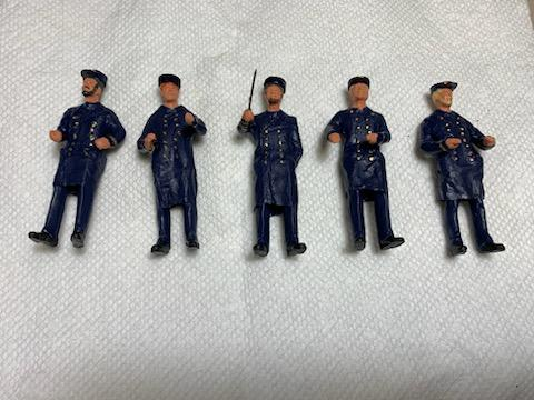
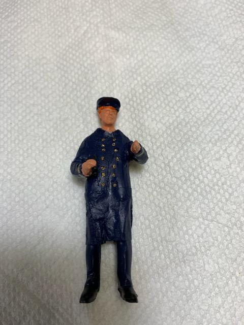
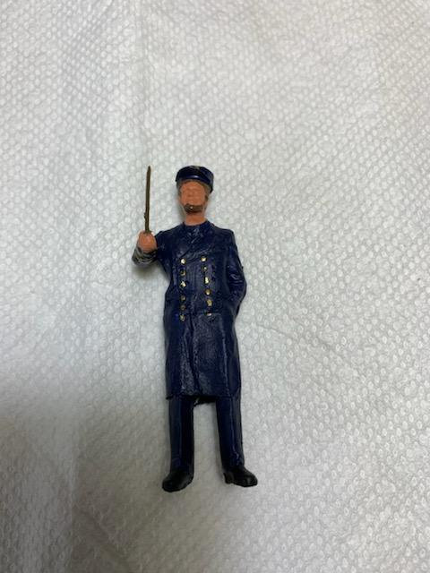
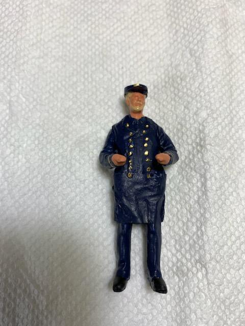
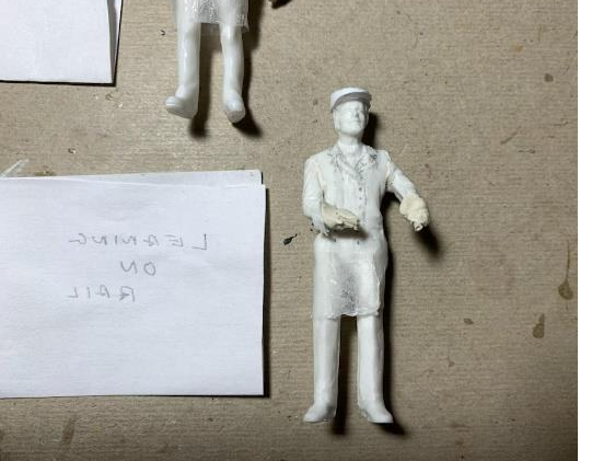
Happy New Year! Here's the latest, from October of 2024, mostly regarding modifying and placing the figurines, but also some anvils, just for fun. All photos and captions are by Bill Kammermeyer. Officer Figurines, Continued (Bill Kammermeyer) The figurines (officers and ordinary seamen) shown in the July Newsletter have been modified by Bill Kammermeyer to better reflect more realism and historical accuracy. Figures before modifications Figures before modifications Figures with more realistic/softer, better-fitting hats, also with facial hair. Sculpey added to figure, to add mass and softer lines. Officer figure initially designed by Bob Temper, plus a modified head, unpainted. Bill has been working on these figurines for both the USS St. Louiss and the Hunley dioramas. Not only painting and animating them, but also staging them to look as natural as possible. ANVILS That's all for now. More on the Figurines and other fun stuff coming soon. Please to enjoy. Tim Jovick 314-761-5435


-
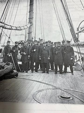
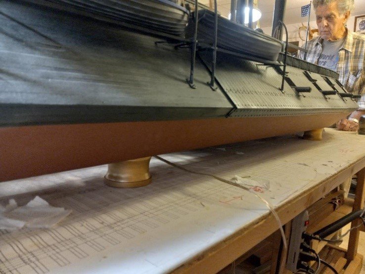
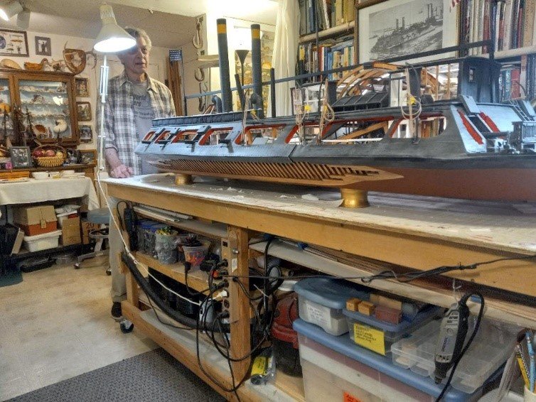
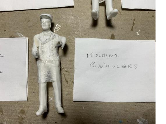
OFFICER FIGURES, Continued: Photo of offices aboard the USS St. Louis. Officer figures, some with beards, jackets painted a dark blue with gold buttons. The Notice that the jackets are about knee-length and Kleenex lengthens the jackets quite nicely. are either open at the neck or buttoned up, with a double row of gold buttons. The hats are flat on top, with a stiff bill in the front. Officer with binoculars. Officer with pointer. Will likely be placed in Captain’s cabin, pointing at a map on the wall. Officer with hands on rails. PEDESTALS (To rest the gunboat on the stand) This is one of two proposed sets of pedestals for the USS St. Louis to rest on. There are four, two at the bow and two at the stern. These are 2-1/4” by 4” and painted gold. There is a hole in the stern starboard pedestal to allow the wiring from the boat to go down into the stand unnoticed. Another set is painted brown and is somewhat taller. That's all for now, which briings us up to July of 2024. The next entry will be from October 2024 and will have more on modifications of the figurines.
-
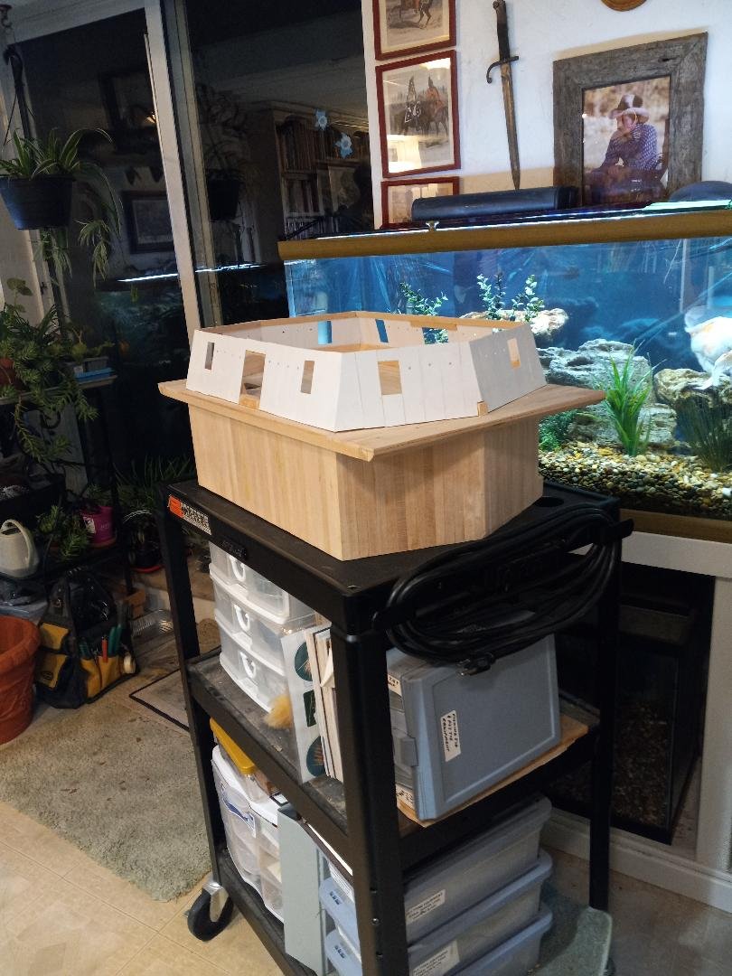
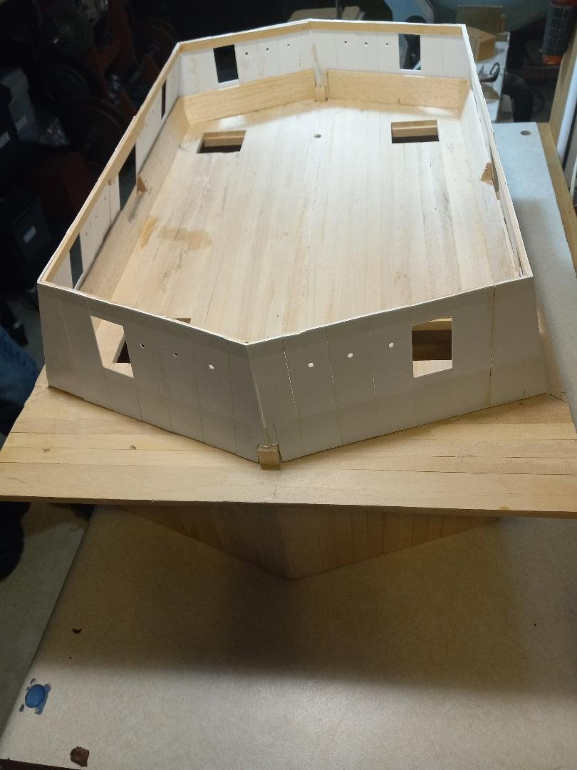
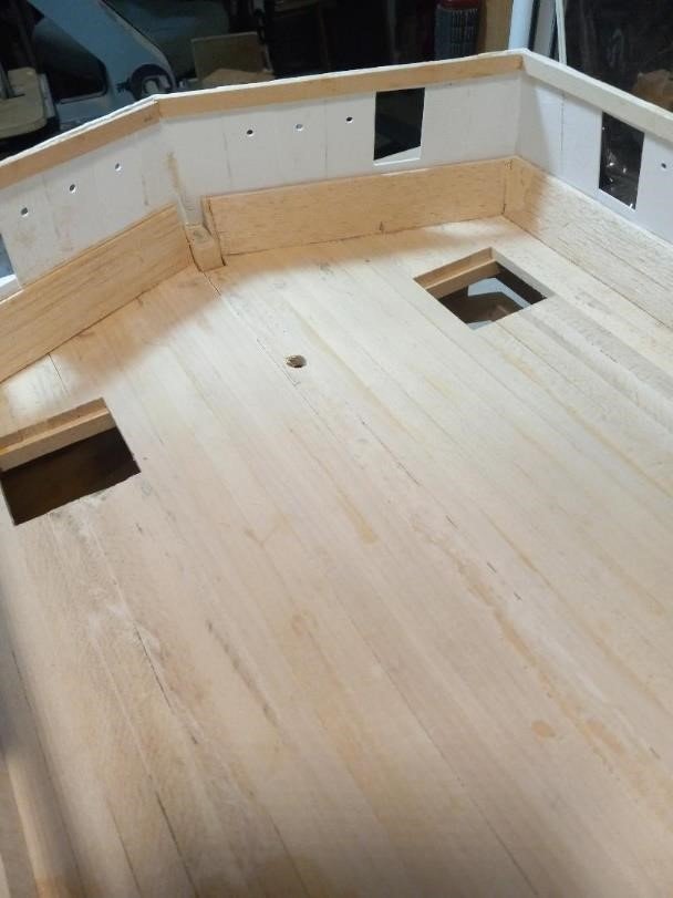
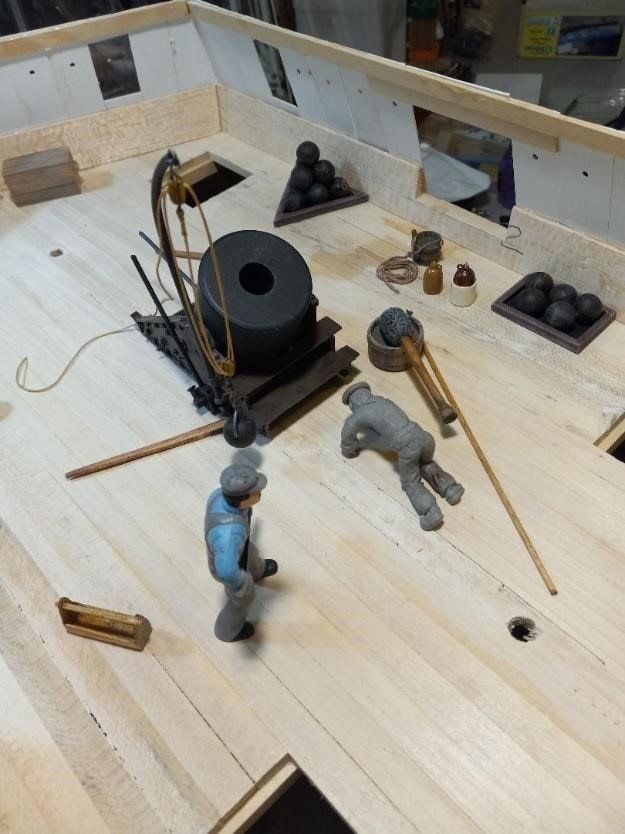
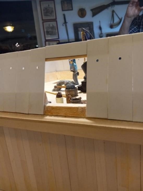
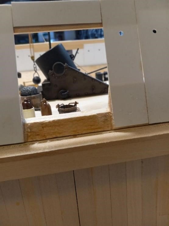
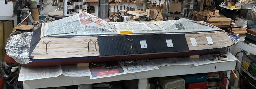
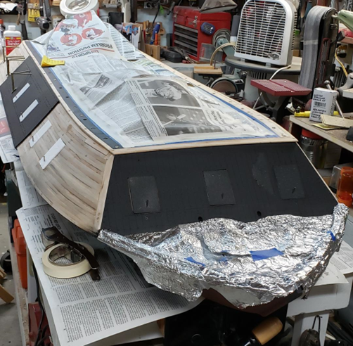
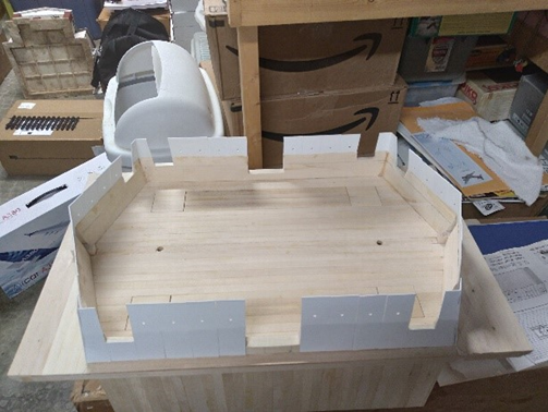
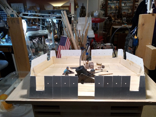
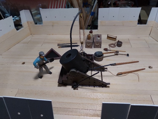
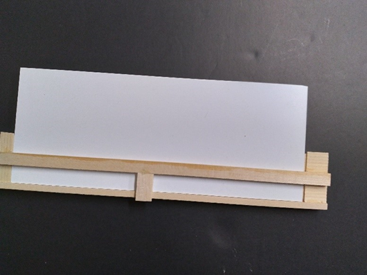
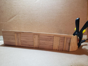
MORTAR BARGE UPDATE (Bob Keeler) I redid the upper walls to more accurately reflect the scale seven-foot-tall scale (1/24). They are made from .040” plastic sheeting and are 1¼” tall (as opposed to a previous try, which was 1” high and found to be too short). The walls lean in at a ten-degree angle. The supports are made of balsa “trailing-edge” planks, which are used in R/C airplane models, glued together. Holes for doors and windows had to be recut to reflect placement on the 7’ scale. Doors and windows will be fashioned to scale. Interior of walls, floor supports and upper supports. Interior view, with previously constructed (by Bill Kammermeyer) mortar, cannonballs, equipment/tools, and figures. View through door Another view through door That's all for March/April of 2024. The next entry will be from July of 2024 and will look at further work on the Offier figures and pedestals for the gunboat. Coming soon! Tim Jovick
-
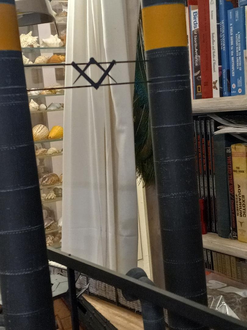
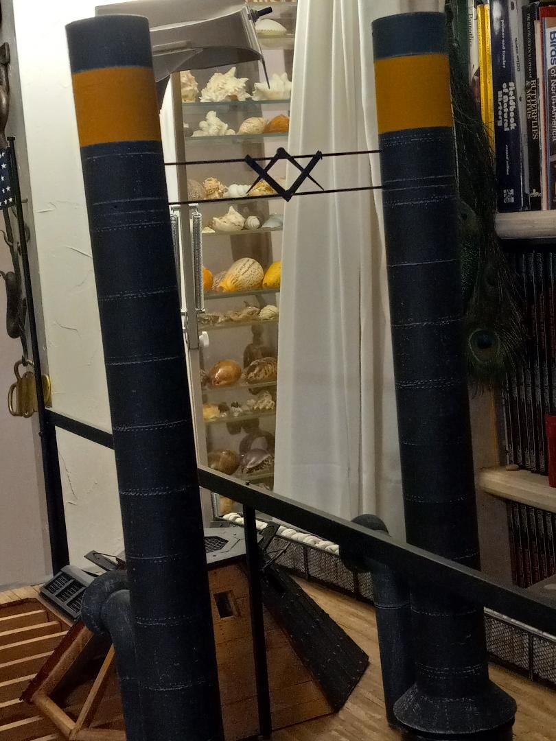
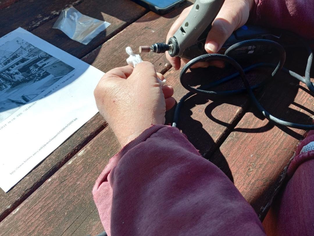
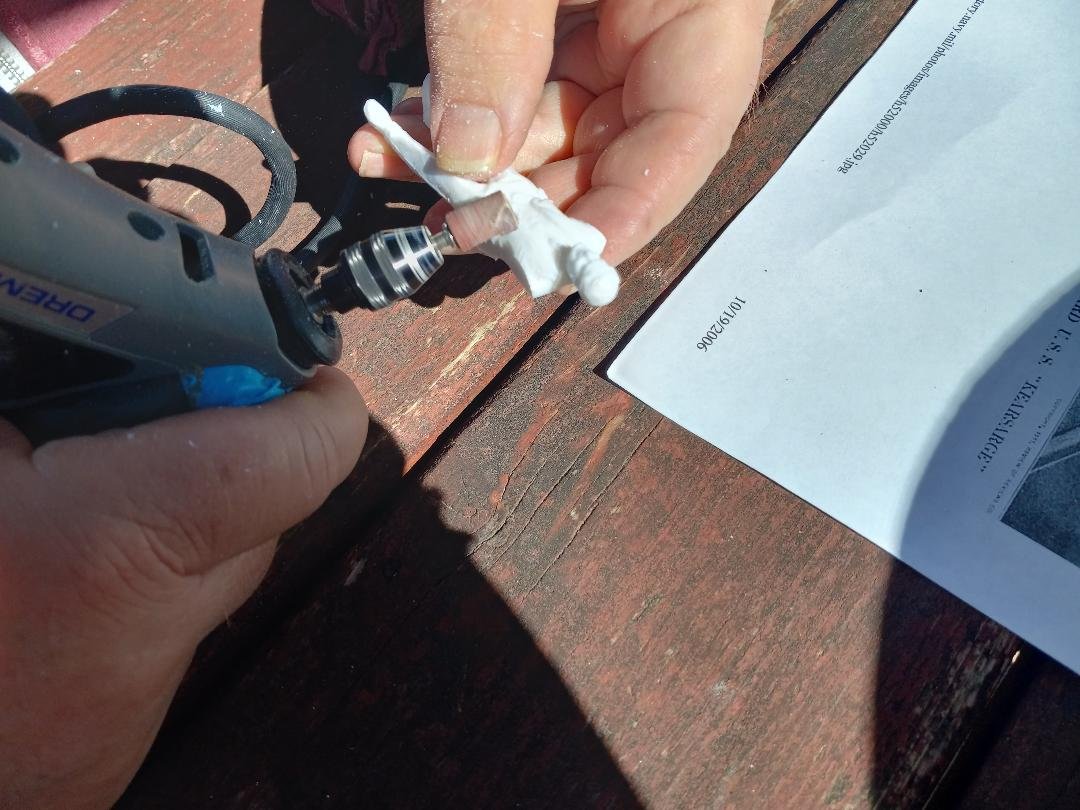
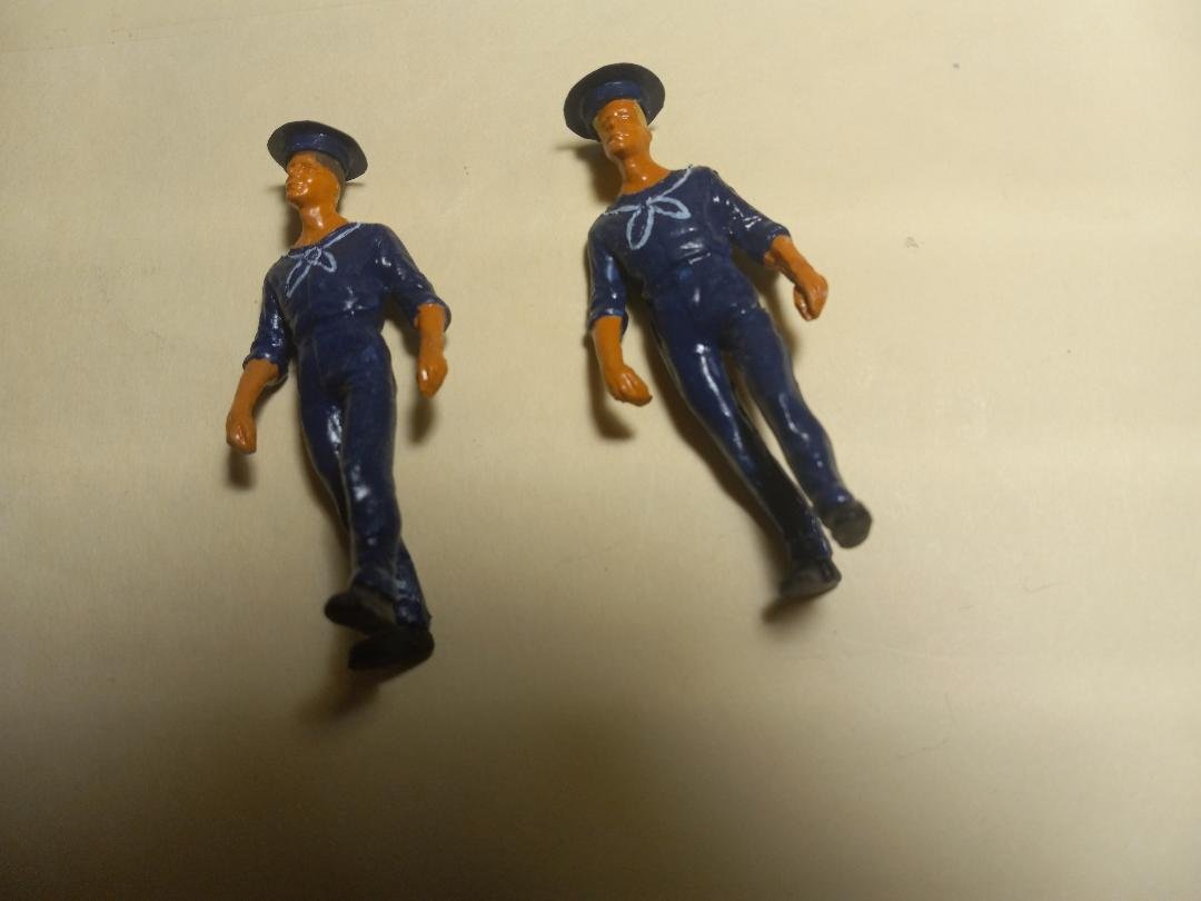
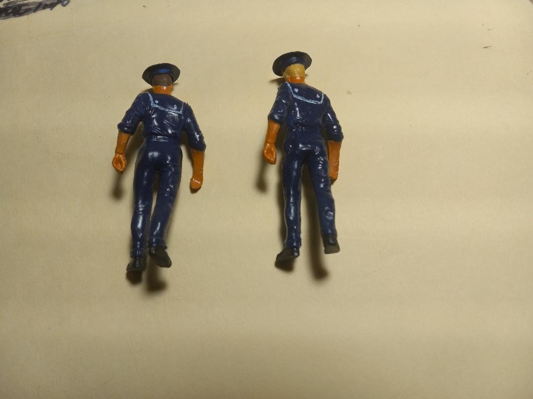
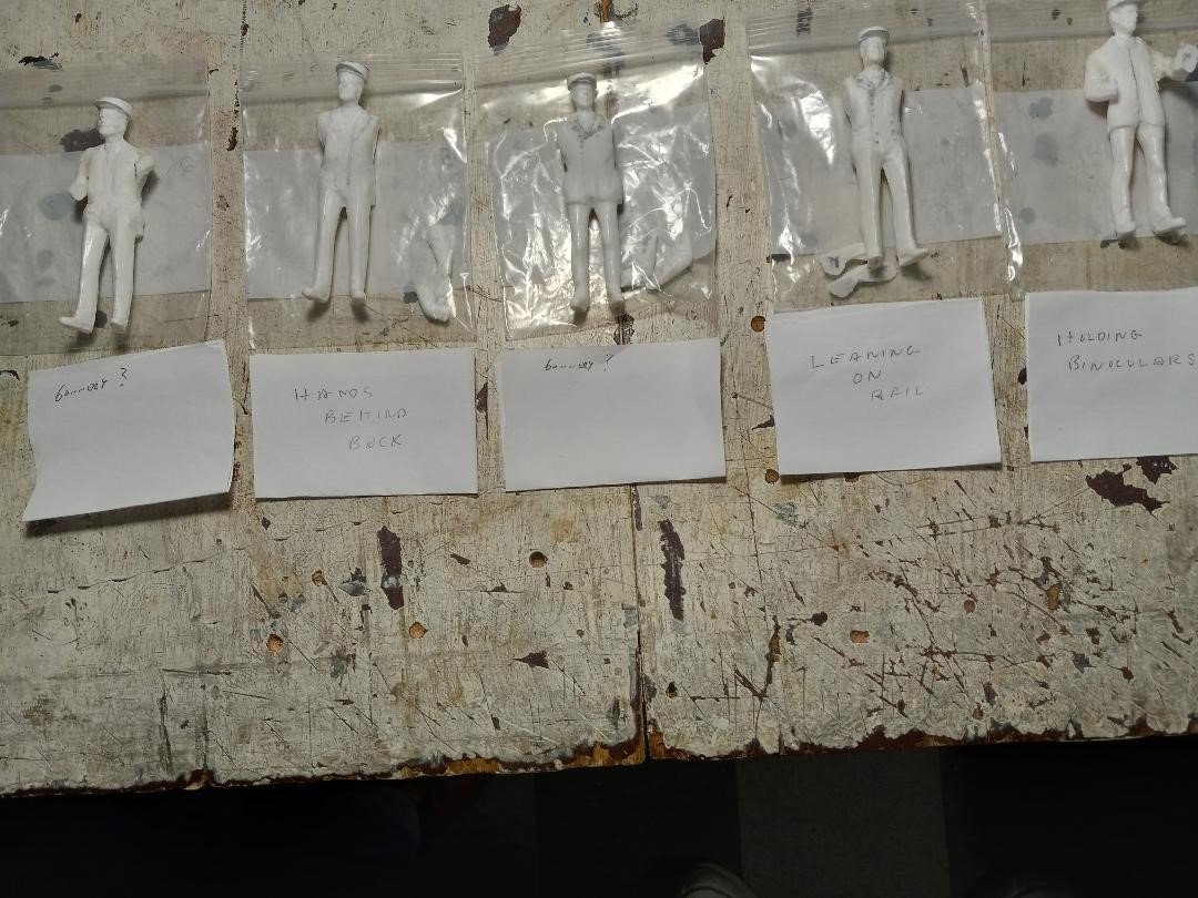
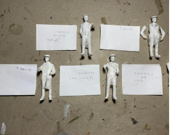
Hi all, back with some more pictures of our USS St. Louis project. Again apologies for the delay in posting. As of this writing, we're still closing in on completing the gunboat, mostly figurines, but also other mini-projects. Unless otherwise noted, alll photos and captions are by Bill Kammermeyer. Completed smokestacks, painted, with Masonic symbol attached, painted black (Note Bill's seashell collection in the background). FIGURINES: OFFICERS AND ORDINARY SEAMEN (made by Vince Murphy and Tim Jovick) Making figurines from 1/24 scale plastic figurines, male, with suits or regular shirts and ties. Procedure is to cut off the arms, at least for the officers (the figures for the Ordinary Seamen already had rolled-up sleeves), and grind off areas such as ties and pockets, as well as molding seams. This required delicate work, using not only grinding attachments but also small /dental burrs. (ta follow-up note: These figurines were in the Model Railroad section of the hobby shop we go to (Schaefer's in St. Louis), but when we recently went to purchase more, we were informed that they are no longer available, as there were veery few customers that had wanted them). Ordinary Seamen figures. The hats were made from plastic tubing, with the tops of the hats made of plastic sheet cut into circles. The front neckerchief and back flap were outlined with a scribing tool. These appear to reflect the period pictures and drawings. Officer Figures, after grinding off irrelevant details. Hats made of plastic tubing, with bill made from plastic sheeting . Hats “filled in” with plastic wood filler. The labels indicate what function each figure will be doing, at least at this point. Thus, there are two gunnery officers, one holding binoculars, one leaning against the railing, and one with his hands behind his back. A good deal of work still needs to be done on these figures, including modification of the arms and hands, lengthening the jackets to about knee-length, and placement of many buttons on each side. Officer figurines with coats lengthened using Kleenex (toilet paper was too flimsy and paper towels were quilted). After wrapping around the figure from waist to knee, they were stiffened using thin CA glue. Additionally, the coats were modified to make them appear to be closed. Rows of buttons (eight on each side) were marked and then shallowly drilled with a small drill in a Dremel, to be filled with a Pentel gold-paint pen. That's all for today. Next entry will be progress on Bob Keeler's 124 Mortar Barge

-
timboni reacted to a post in a topic:
USS ST LOUIS by thorn21g - 1:24 - POF - Civil War Ironclad - Gateway Model Shipcrafter's Guild
-
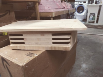
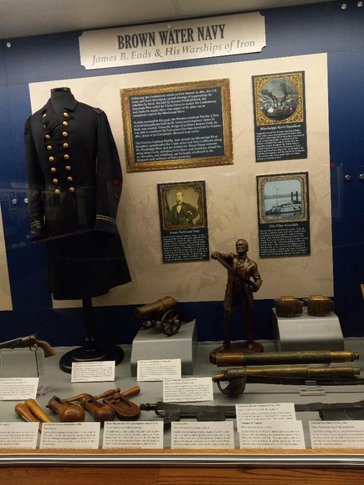
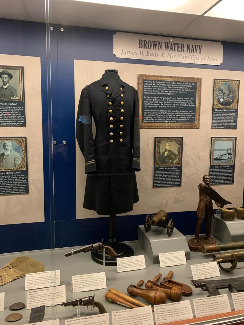
Hi all, It's been quite awhile since I posted, so, with apologies, and with massive gratitde to Kurt Van Damm, who guided me through a myriad of glitches and false starts, herein we do some catching up: TRIP TO MISSOURI CIVIL WAR MUSEUM Several members of the Gateway Ship Crafters visited the Missouri Civil War Museum, which had commissioned the USS St. Louis project. We spoke with Mark Trout, Director of the Museum, who gave us a tour and showed us a couple possible places where the USS St. Louis will be displayed. Very impressive place, would recommend visiting it. The address is 222 Worth Road, St. Louis MO 63125. Their phone number is 314-845-1861. Below are a few pictures relevant to our project: This is the display of the “Brown Water Navy,” referring to the seven sister ships of which the USS St. Louis is one. It has, among other things, a statue of James Eads, designer of the Eads Bridge, who designed these gunboats. Closer view of an Officer’s uniform, which we are using as a guide in making the “Officers” figurines. Stand for the USS St. Louis, made of oak, with a groove around the top to insert the sides of the acrylic case, which has yet to be made. This is a beautiful piece of woodwork, which is actually lighter in color than the photo appears. That's all for today, I'm exhausted! More coming in the next few days. Thanks again, Kurt! Tim

-
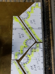
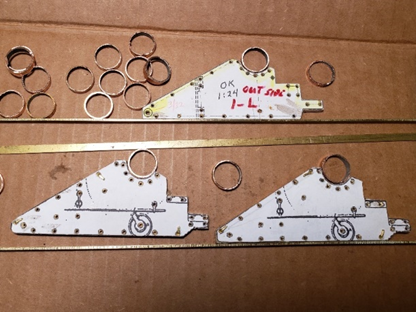
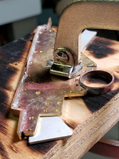
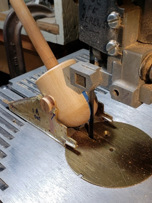
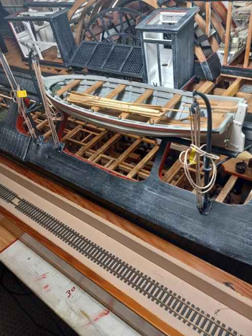
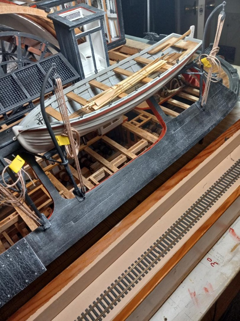
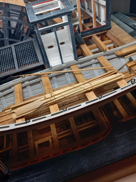
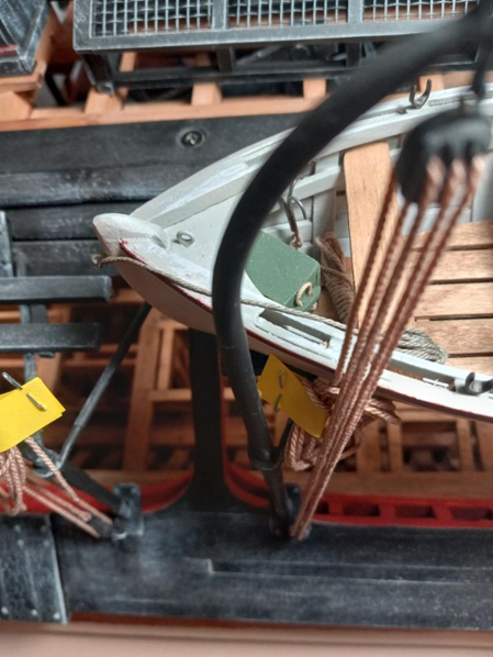
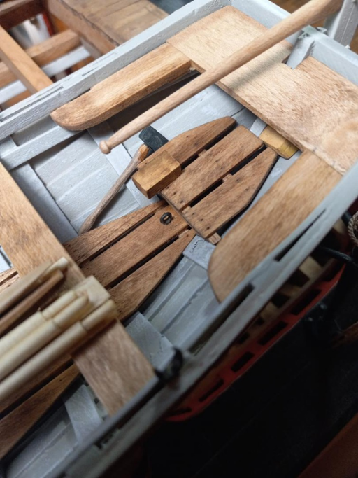
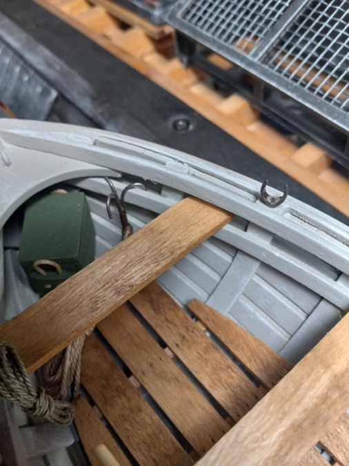
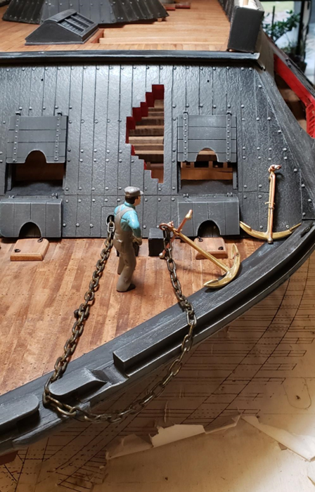
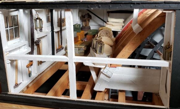
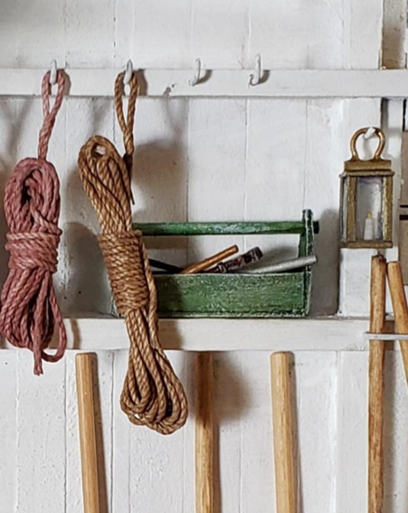
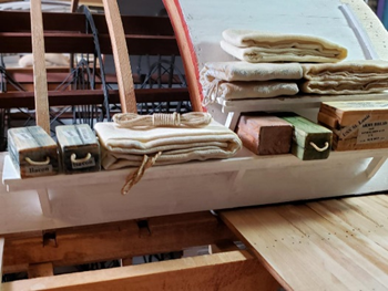
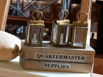
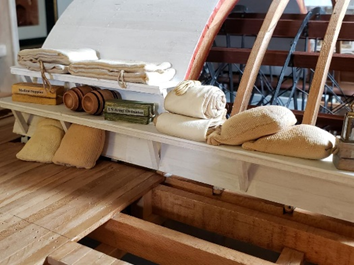
Hi all, and Happy New Year! Bill is still working on the figurines, but in the meantime, here are some pictures of one of the ship's boats on davits, with tackle, and also some items such as oars, a boat hook, a box for smaller items, a grappling hook, an axe, and several lengths of rope. (The "railroad track" is in fact part of a ropewalk device made by Bill) Tim
-
Thanks, Howie, always good to hear from you. Hopefully we will be able to wrap this project up soon, and then hopefully get the Civil War Museum to actually communicate with us as to installation. Will keep everyone posted. Happy New Year! Tim
-
Don, this project was commissioned by the Missouri Civil War Museum, located on Jefferson Barracks (now a veterans' cemetery) in St. Louis. To be honest, there have been some communication problems between us and the Museum's director, so we're uncertain if and when the installation will be done. Hopefully it will come to pass, and if so, I'll be posting some pictures of the dedication/installation ceremony. Thanks for asking. Tim
-
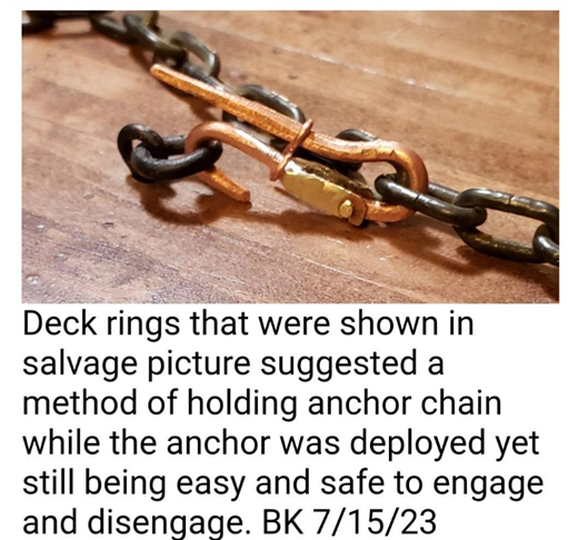
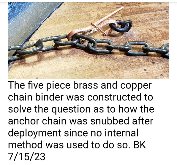
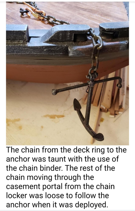
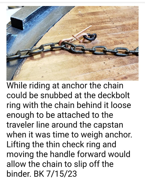
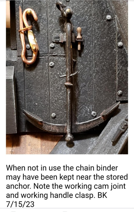
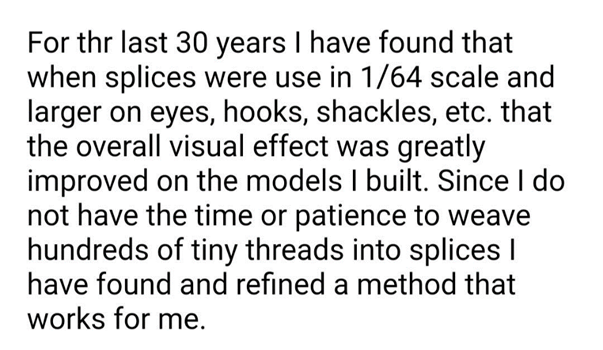
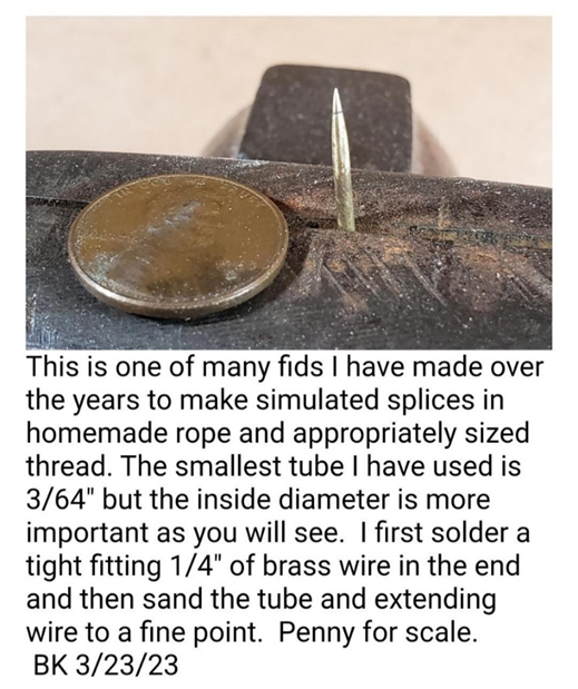
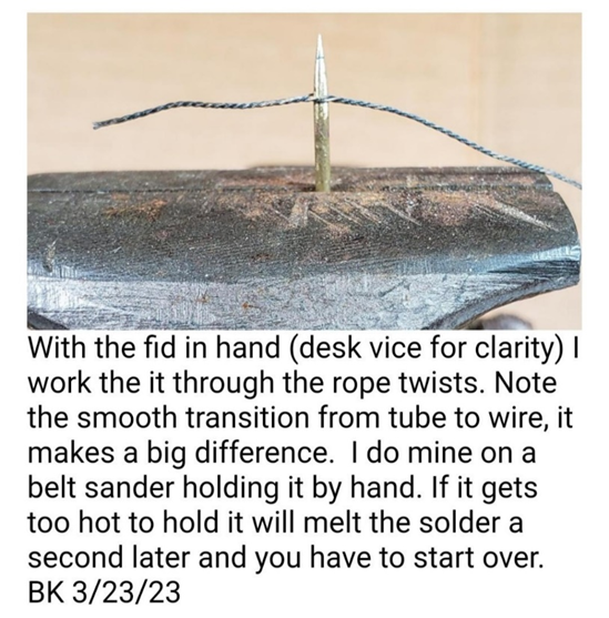
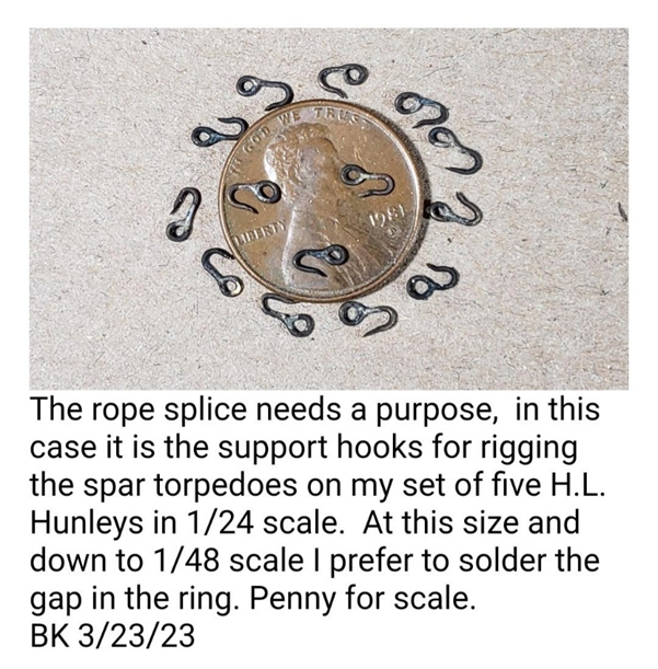
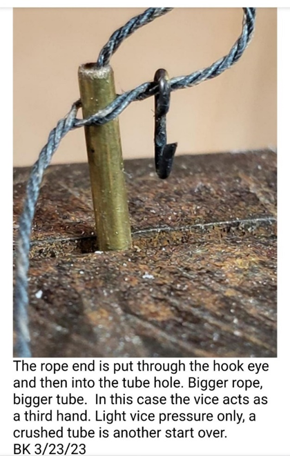
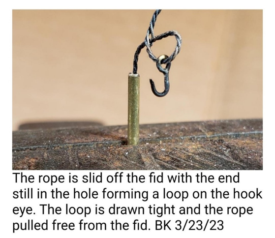
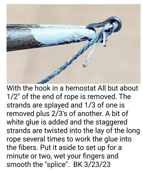
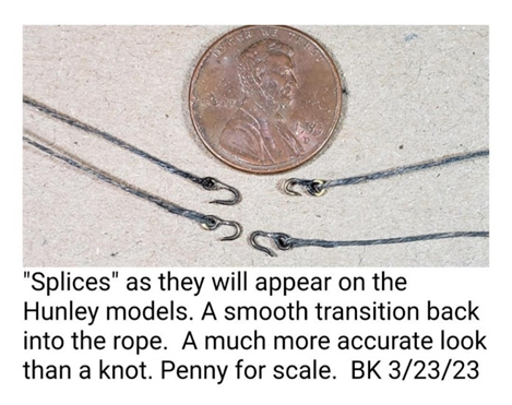
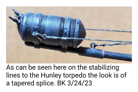
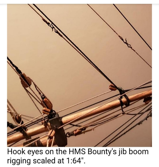
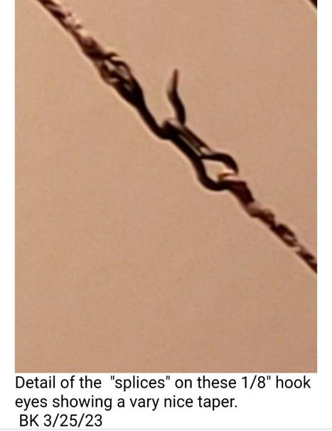
Hi all, This entry is from July, 2023 and looks at making a chain binder w/ slip handle, and how to do splices using a homemade fid: LEVER CHAIN BINDER WITH SLIP HANDLE This device answers two questions on the fore deck of the St Louis. Number one, what was the purpose of the large ring bolt in one of the salvage pictures? Number two how did they control the anchor chain when deploying, it snubbing it, and weighing the anchor? This type of lever chain binder may have been used in this period of time. MAKING SPLICES IN ROPES, with illustrations of their uses on Bill’s C. L. Hunley and HMS Bounty (Pictures and captions by Bill Kammermeyer). While not technically OK, folks, we're caught up! The project is almost finished, with most of the effort going to making figurines 1/24 scale. Previous entries have looked at making armatures, heads and some clothing, which will be supplemented by adding specific figures in various poses around the gunboat. Tim 314-761-5435
-
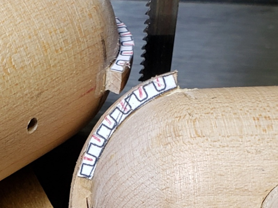
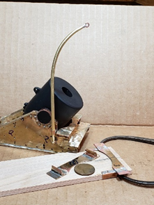
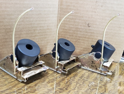
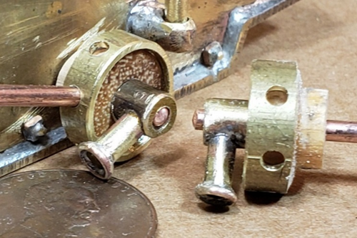
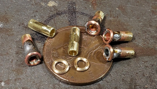
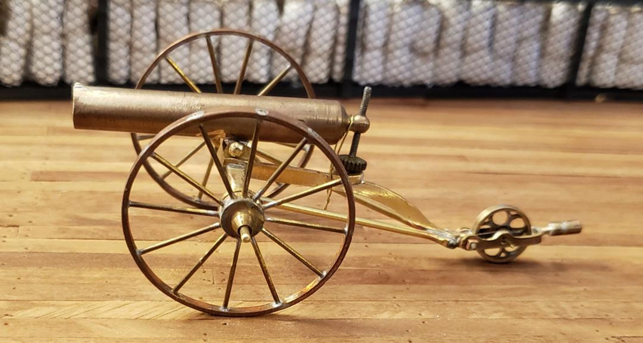
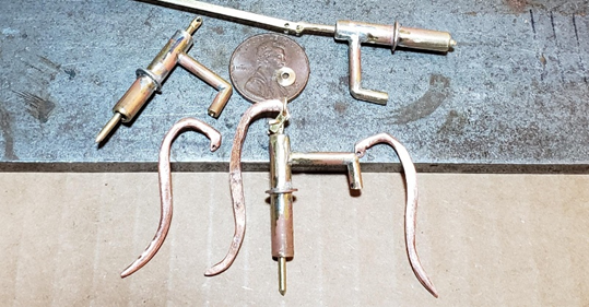
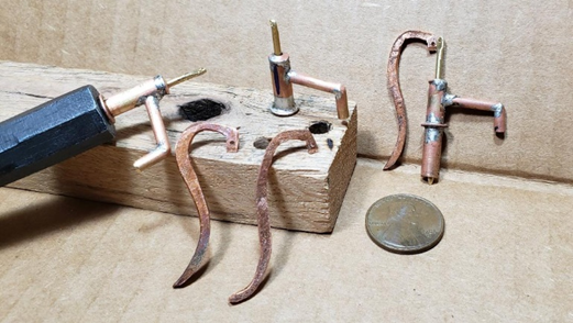
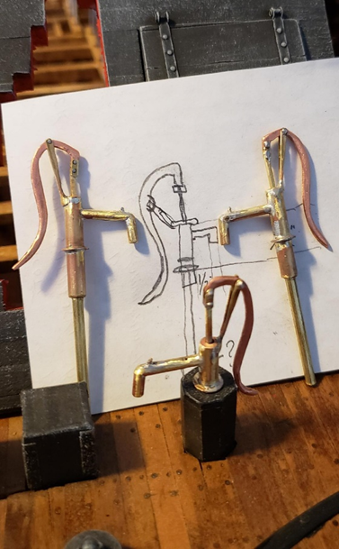
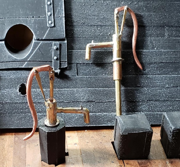
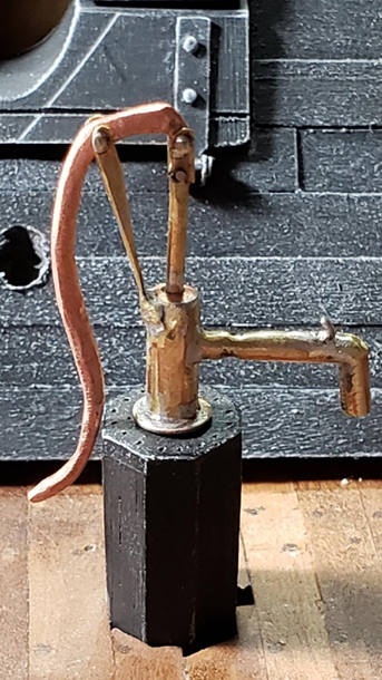
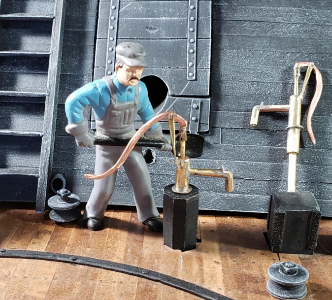
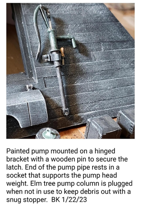
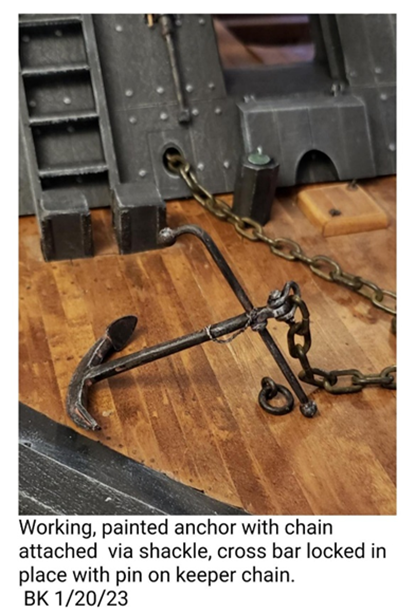
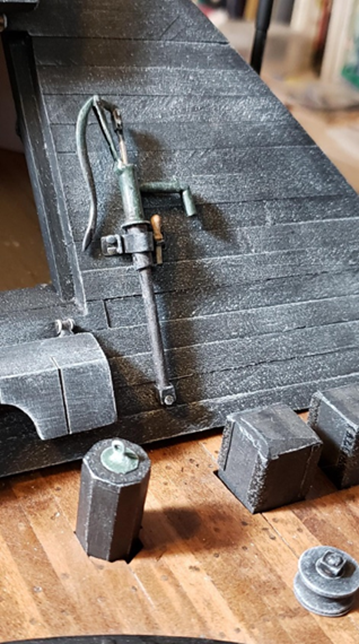
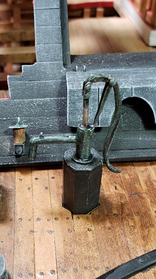
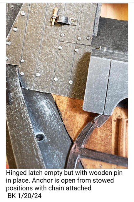
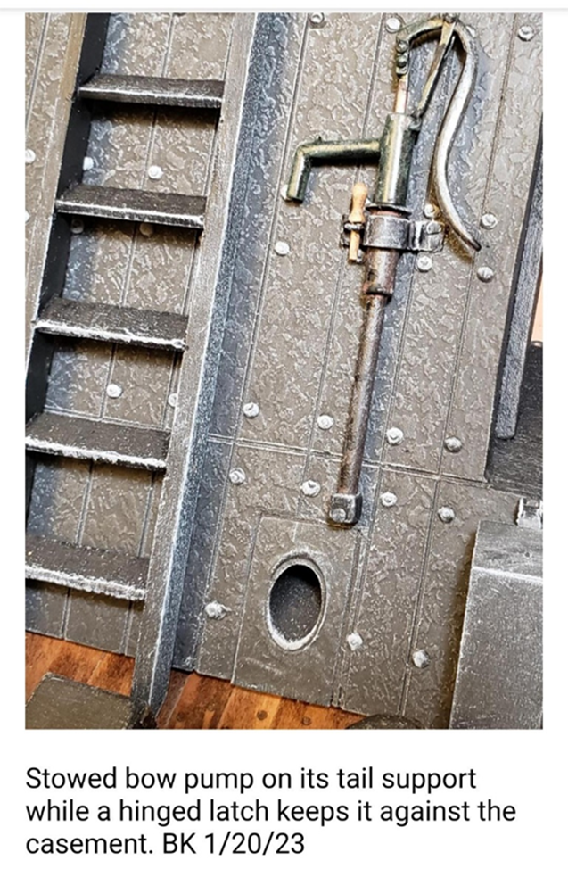
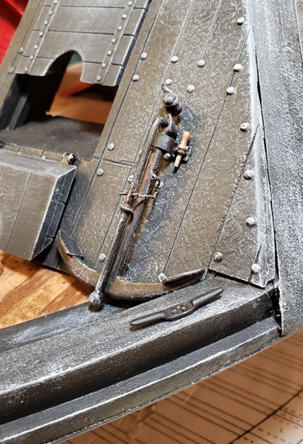
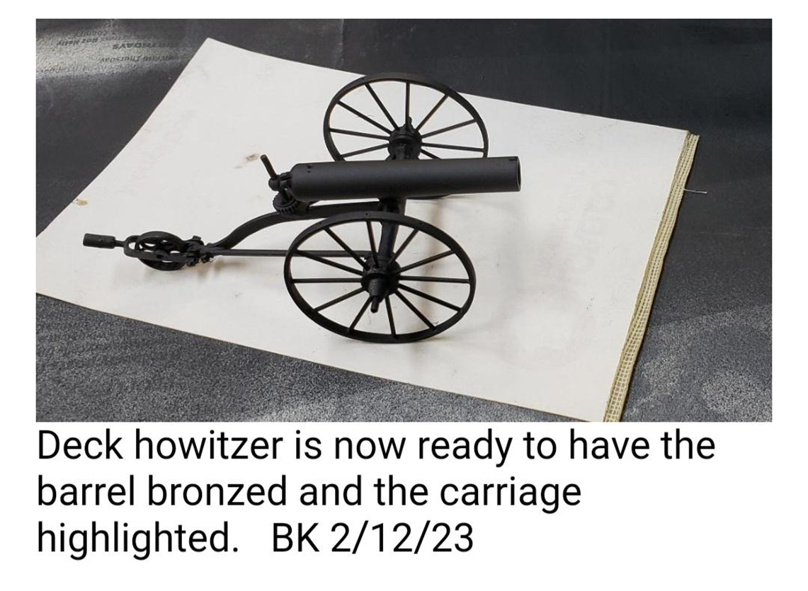
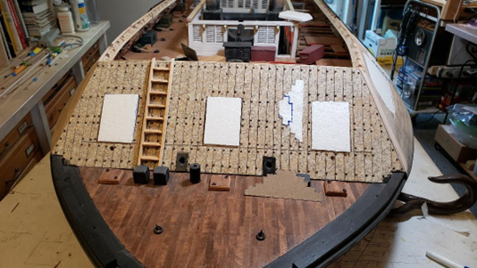
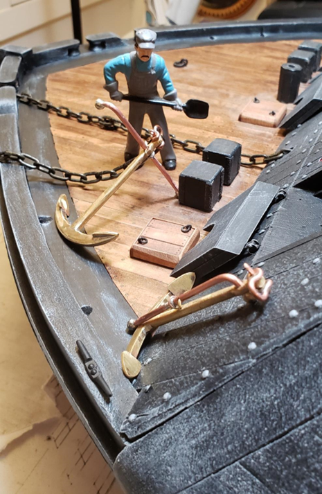
Hi all, This next installment is from January/February of 2023. 12 Pound Deck Howitzer BK 11/23/22 Deck Pump Heads Three octagonal "oak tree pump" shafts were made 4 years ago by Vince and Tim and installed in the bow and stern decks as per the Cairo plans. No pump heads were shown on the plans. Research shows that hand pumps were removable and stored on deck casements. I found a number of period pumps and drew plans for plausible type. These were used to empty the bilges, not as emergency water removal. In an emergency, the ship was run aground and the emergency addressed. Brass tube, rod, sheet stock and 14 guage copper wire were cut and soldered. The hardest part was attachment points so the pump handles would work the internal pump rod. BK 1/4/23 Plan that I drew as guide for pump construction behind the finished pumps. The 2 in back will be mounted on the casements. The tail pipes will fit into a water-tight fitting to create a vacuum after the pump is primed. BK 1/11/23 The mechanism that drives the pump rod works well, and all pivot points pins are soldered in place in a fashion that allows movement. When they are painted this feature may disappear. BK 1/11/23 The pump heads rotate 360° with a nib on top of the spout to hold an attachment for a leather or heavy waterproof cloth hose to take the foul water over the side. No internal discharge was shown on the plans. BK 1/11/23 Our scale figure shows relative size of the pumps. When in action, the pumps needed to be stowed to avoid damage by cannon discharge. BK 1/11/23. Painted pump mounted on a hinged bracket with a wooden pin to secure the latch. End of the pump pipe rests in a socket that supports the pump head weight. Elm tree pump column is plugged when not in use to keep debris out with a snug stopper. BK 1/20/23 Painted, working pump head in the elm tree well that goes into the port bilge. The plug is stored in the pump tail support on the casement. BK 1/20/23 Port anchor painted and stowed against the bow casement in its hinged latch with a wooden pin to secure it. BK 1/20/24 That's all for this time. Next will be the fashioning of anchor chain binders. See you then! Tim 314-761-5435
-
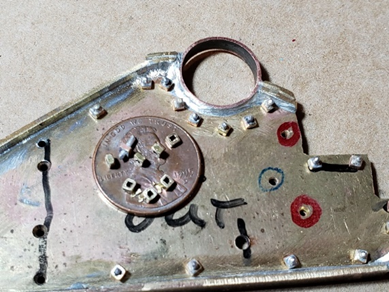
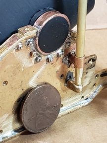
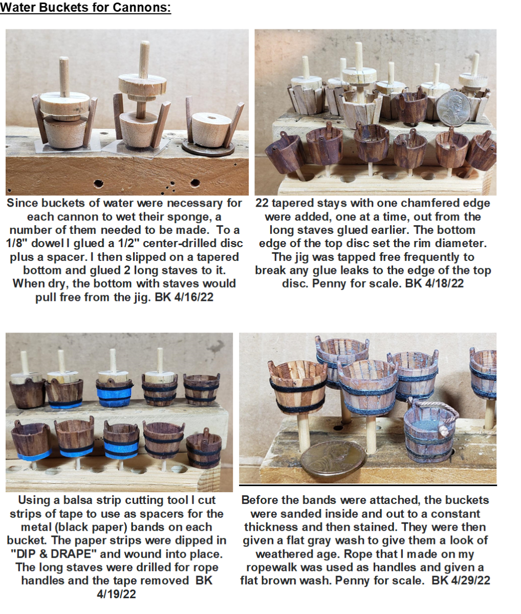
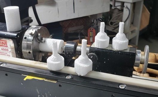
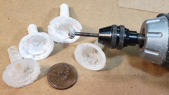
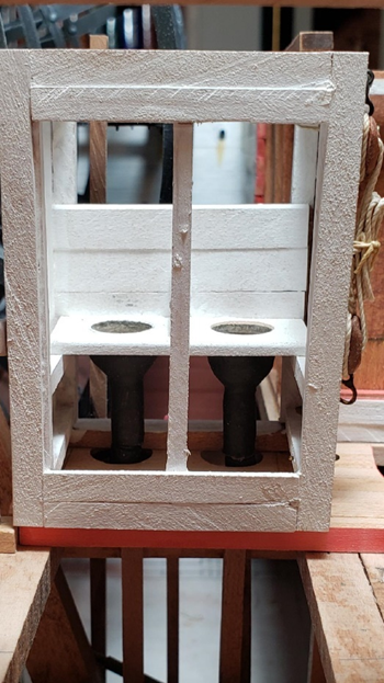
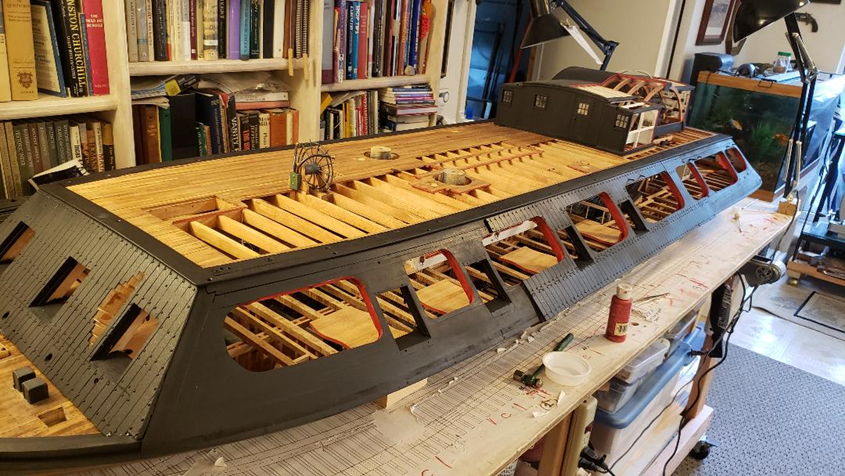
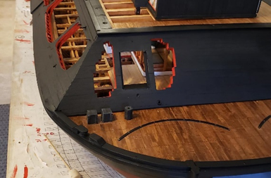
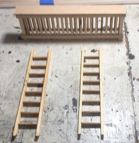
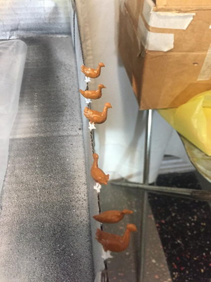
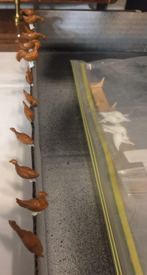
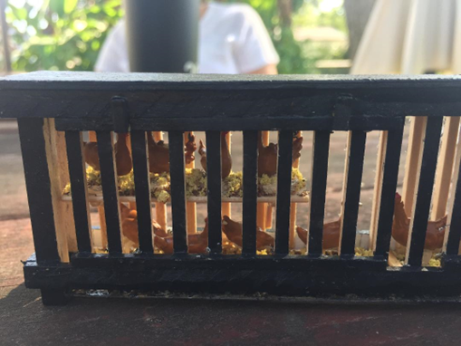
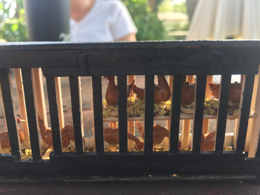
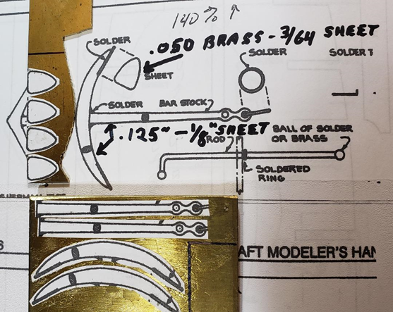
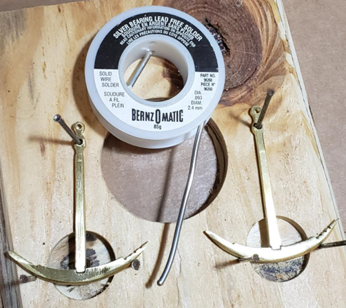
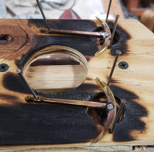
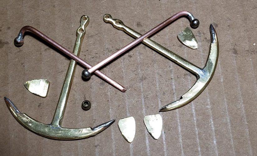
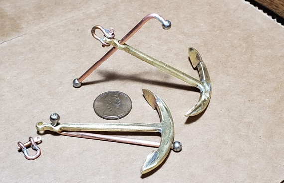
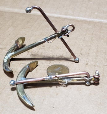
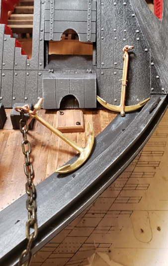
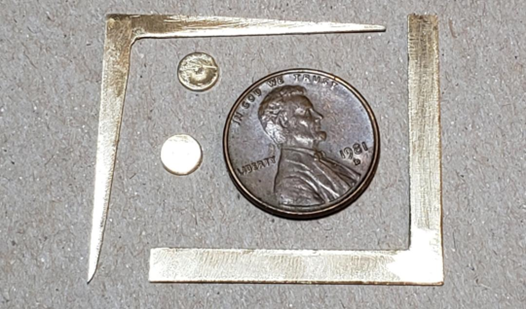
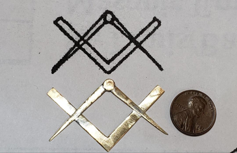
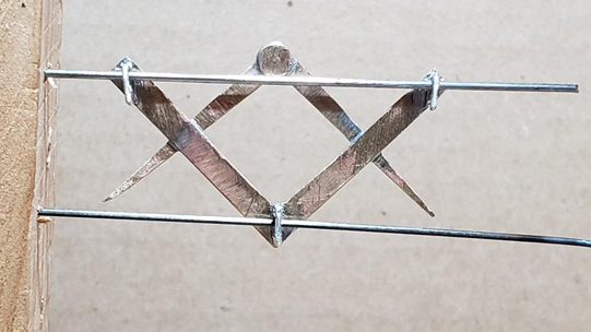
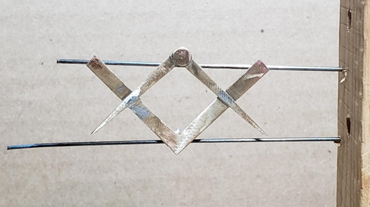
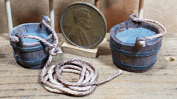
OK, this next session cover much of 2022, and covers not only further progress on the USS St. Louis , but also progress on the accompanying Mortar Barge built by Bob Keeler. USS ST LOUIS (Photos and text by Bill Kammermeyer unless otherwise noted) In the pilot house, the lanyards for holding the armor plate window lids open are put in place around their pins. LED lighting has been put in place as a trial. Fred and I are looking into fiber optics for the candle flame. BK 3/21/22 CREW HEADS: The difficult mechanism for building the plumbing apparatus for the crew heads was as overcome by turning Styrofoam molds to be covered with liquid epoxy in the shape of a bowl and pipe using a pattern and duplicator. BK 4/24/22 The Styrofoam mold was trimmed and then removed from the dry epoxy bowl shapes using a moto tool with a round bit. After most of it was removed, a drop of acetone melted the rest. The rims were sanded flat. BK 4/26/22 The bowls were painted copper on the inside and black outside. The flat edges of the bowl were glued to the underside of the seats of ease with the pipes making a right-angle turn into the waterway. A drain from the starboard upper head may be seen with a stain in the background. BK 4/28/22 MASKING AND PAINTING OF THE CASEMENTS: Blocks of Styrofoam were cut, with Vince and Tim’s help, for a tight fit in the gun ports and open viewing cuts. BK 6/9/22 With Styrofoam plugs in place and masking complete the casements and the upper portion of the hull are ready to be painted. BK 7/27/22. Bow and stern casements were painted off the ship and the side casements are ready to be painted. Aluminum foil works very well with irregular surfaces. BK 7/27/22 Painting went off without a hitch. The Styrofoam plugs worked very well. The use of a flat red paint to designate removed sections of casement were applied. BK 8/4/22. All the edges of the gunports as well as well as the removed area had to be painted flat black and flat red respectively. BK 8/4/22. SPITOONS, CHICKEN COOP AND LADDERS: Using beads as the base and paper as the rims, Vince and Tim made a number of spittoons for placement around the ship. Pegs were attached to the bottoms of the spittoons so they could be placed solidly in holes drilled in the decking. They were painted brass. (see below regarding “straw” for the flooring of the coop) Chicken coop (unpainted), and ladders for bow and stern casements, made by Vince 1/25 scale chickens (hard to find, gotten from a Canadian company) white (see on right), painted brown, in preparation for their becoming residents of the coop. They came with pegs on the feet, for anchoring on the coop floor, and these pegs were placed in the end of a piece of corrugated cardboard while the paint was drying. VM/TJ 9/9/22 Coop painted black. Floor had standing chickens (including one rooster). Upper shelves had “nests” made from buttons. The legs were cut off these and the hens placed in the “nests” as if they are laying eggs. The “straw” for the floor and shelves was made from scale “rough grass’ and “dirt.” ANCHORS: Research plans for an Admiralty anchor were printed to the proper scale, cut to rough shape and rubber cemented to brass sheet. 1/8" for the arms and shanks. .0218" for the palms. BK 10/28/22 The brass parts were cut to pattern size, filed, and sanded to final shape with a notch in the top of the arm and a shoulder filed on the end of the shank for a stronger soldered joint. These parts were pinned to scrap wood with a hole under the joint so the wood would not act as a heat sink. BK 10/30/2 The joints were fluxed and then overwhelmed with torch heat. Silver bearing solder was touched to the joint and I was done. A solid joint that just needed to be cleaned and filed. BK 10/30/22 The finished joints after filing and sanding were smooth and true. 12-gauge copper wire was cut and bent as per plans with balls added to the ends. Balls were from an old brass bead chain with the links cut and one end drilled for the cross arm. BK 10/30/22 The palms and notches in the arm tips were fluxed and tinned, then spring clamped together and torch soldered while in a vise. The clamp was removed and palms were finish set using pliers and torch. Balls were soldered in place. Penny for scale. BK 10/31/22 Shackles were made from 14-gauge copper wire. Stop rings and retaining pins were made of 22-gauge brass wire. Pins were drilled and 28-gauge brass wire was twisted and soldered to simulate the keeper chain. Anchors shown in working and stowed positions as they will be displayed on the bow deck. Penny for scale. 11/5/22 Anchors displayed on bow deck, top view View from the bow. The anchors store more easily with the cross bar stowed. MASONIC SYMBOL: The existence of a Masonic symbol located hanging from the support rods between the smokestacks is seen in some period pictures, although it has been difficult to verify. It is known that the USS St. Louis was renamed the USS Baron DeKalb (named after Johann DeKalb, a French military officer who served as a Major General in the Continental Army) in September of 1862 when it was transferred from Union Army service to Union Navy service. Her last Captain, Lt. Commander John Grimes Walker, was known to be a Mason. It is also known that during combat, Masonic members would not fire upon other Masons, even if they were the enemy. (thanks to Casey Jovick and Keith Dockins for their research assistance). Thus, despite the speculative nature of this symbol, it was decided to construct one, which could be removable but still part of the display if need be. Sheet brass .021" from an old award plaque was cut to make the square, compass, and hinge buttons. Buttons were made with a Whitney #5 jr. punch. Penny for scale. BK 10/26/22 Assembled parts were tinned, clamped and then flash soldered with a propane torch. Excess solder was sanded and filed away. The result was pretty close to the plans I used. Penny for scale. BK 10/26/22 20 gauge brass wire hooks was soldered to the back for optional mounting between the stacks. It will be firm but not glued, giving us the option of removing it if proof is presented that in fact it was not historically accurate. BK 10/26/22 Finished Masonic symbol as it will appear on the stack support rods viewed from the bow. BK 10/26/22 Buckets to be used on Bob Keeler's 1:24 scale 13" mortar barge (see below). Long rope attached to retrieve bucket when thrown over the side to refill the sponge tub. Stained water in buckets is liquid steel. It dries level and has a water sheen. Penny for scale. BK 4/21/22 MORTAR BARGE, Continued (photos and text by Bob Keeler, 06/03/22) Shows .04 in x 1.25 in x 3.25 in styrene shielding representing 1 in x 30 in x 7 ft iron shielding on wooden supports. Side view View showing Bill’s mortar and supporting hardware with our scale man for perspective. No, I didn’t paint the shields black; just the lightingeffect. It does show the rifle ports to advantage. Another view showing the interior details Tool for cutting styrene into 1.25 in wide strips Tool for cutting strips to 3.25 in length. Right hole is for drilling 1/8 in rifle holes; left hole is for locating hawser holes in 4 pieces. After doing all this, it didn’t look right. When I went back to the plans, I found out that I had made wrong calculations. The supports should have been 1 in. high instead of 1.75 in. high, and the shields should have been 1 in. wide (24 in wide) instead of 1.25 in. wide (30 in wide). So I will remove these supports and shield and build new correct ones. WHEW! Lotta stuff there! Next installment will be from January/February and will look at the deck howitzer and the pump heads. Tim 314-761-5435


-
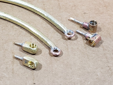
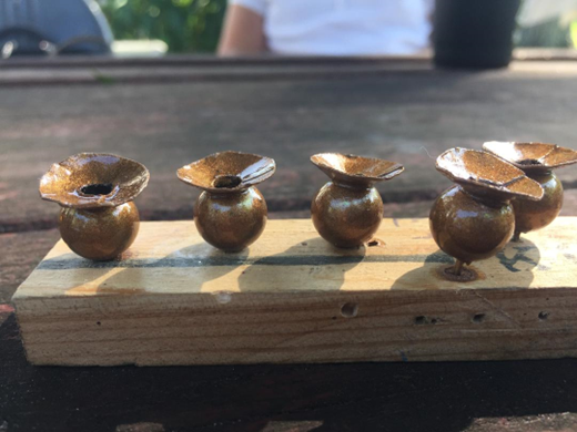
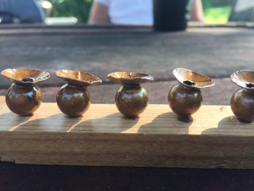
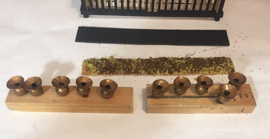
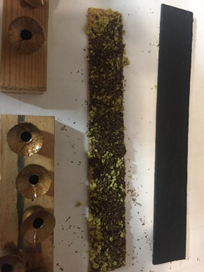
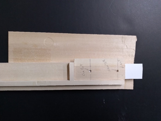
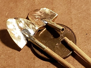
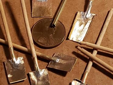
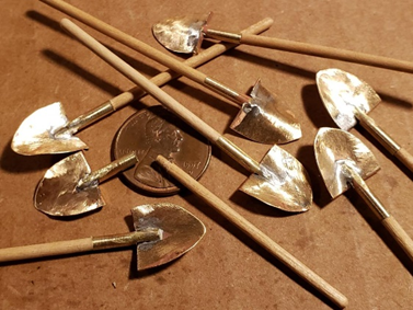
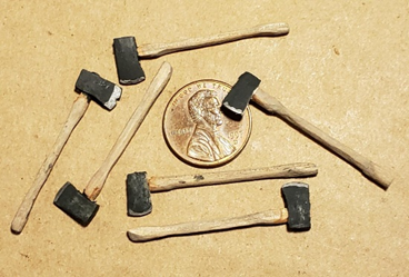
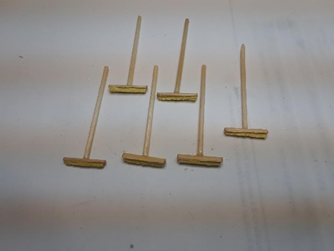
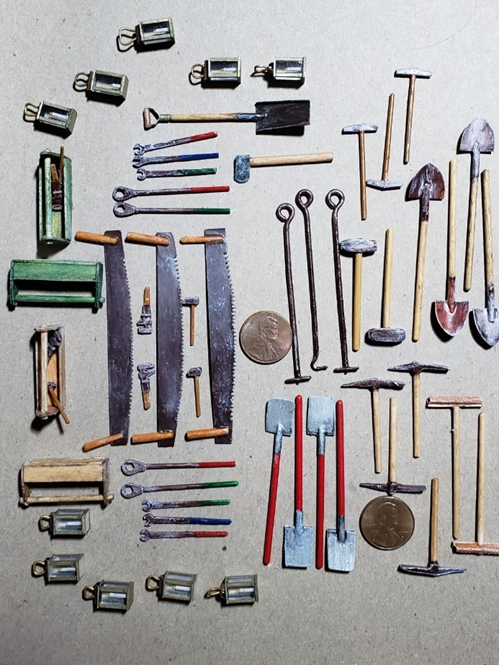
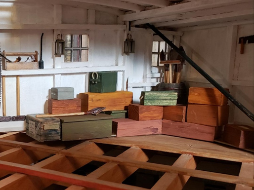
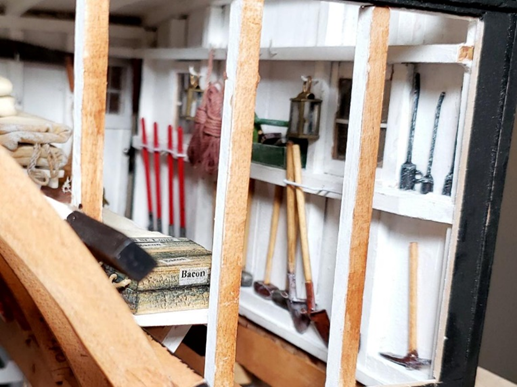
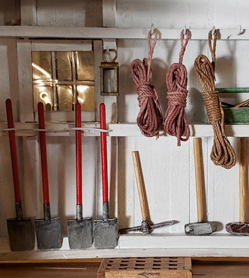
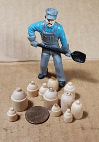
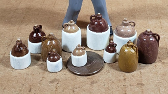
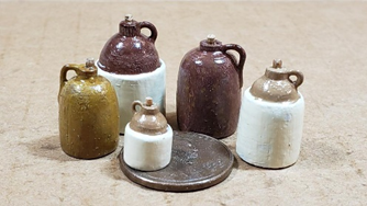
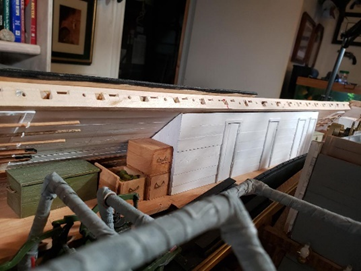
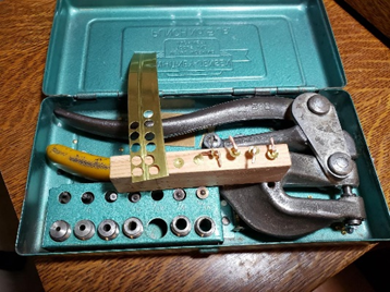
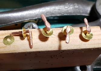
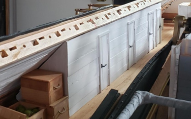
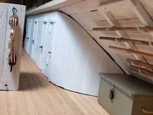
Hi again all, More from February 2022, this time focusing on making and displaying tools as well as ceramic jugs. The former involved several people, including Bill Kammermeyer, Fred Heckr, Bob Keeler, Vince Murphy and myself. Making Shovels I formed blades and soldered tubes to them to make collars. Penny for scale. BK 5/18/21 Using the same size tube with teeth filed into the end (as seen on the penny) a peg is formed that fits perfectly into the socket. BK 5/18/21 Old brass weatherstripping was repurposed into shovel blades with tube shafts soldered to them. BK 5/18/21 Tools, Lanterns, Brooms, etc. Axes built and painted by Bob Keeler 8/9/21 Push brooms by Tim (VM 9/15/21) Oil cans by Vince (VM 10/6/21) Tools for the deck storage sheds and the engine room. Lanterns by Fred. Saws, shovels, sledgehammers, clinker rakes and hook and most painting by Bill. Brooms, mattocks, hammers, wrenches and tool boxes by Vince and Tim. Axes by Bob. Penny for scale. 10/14/21. FH / BK / VM & TJ / Bob K. View into forward work shed with tools in place. BK 10/21/21 Forward work shed corner detail. Front boxes had bottoms reduced to cover "L" of cardboard that was glued to the bottom of the walls to allow the crates to be removed intact when the shed was removed from the hurricane deck. BK 10/15/21 Rear shed tool and equipment placement. BK 10/20/21 Tools and lanterns by everyone, selection and placement by Bill. BK 10/20/21 Detail in rear shed. Rope, sledges and shovels by Bill. Tool box and tools by Vince and Tim, lantern by Fred. 10/21/21 BK /VM-TJ / FH Shelving attached to the curve of the wheel house made sense for added storage in the deck sheds. Canvas sun shade would have been stored here along with miscellaneous everyday ship needs. BK 10/10/21 Unlit and empty lanterns along with beans and general supplies. FH/BK 10/10/21 All sacks, boxes, canvas tarps and barrels are attached to shelves and surface of the wheel house so they will stay in place when the wheel house and sheds are made into one unit that can be removed. BK 10/21/21 CERAMIC JUGS FOR PLACEMENT AROUND THE USS ST LOUIS First I turned them by hand. Penny for scale. BK 1/31/22 Then I attached handles, painted as with a ceramic glaze, and corked them. BK 2/3/22 I made 1/2 gal.,1 gal. and 2 gal. size. Lookin' pretty good! Penny for scale. BK 2/3/22 OFFICERS’ STARBOARD QUARTERS Covered mockup by Vince with thin planks and added doors and corrected after gap. VM/BK 10/28/21 Framed the doors and painted as the casement. Using the fit/sand/fit/sand method I was able to get a tight fit. BK 10/27/21 Using a punch, I was able to make door hardware. BK 10/29/21 Detail of door handles made of bent and worked copper wire with plates made wIth punch. BK 10/20/21 View aft with officers’ cabins installed, painted, doors framed and handles attached. BK 10/19/21 I spent more time than I should for a snug fit for this curved wall. I forgot that boxes would be blocking my handiwork. BK 10/29/21 That's all for now. Next entry will be from October, 2022. Please to enjoy. Tim
-
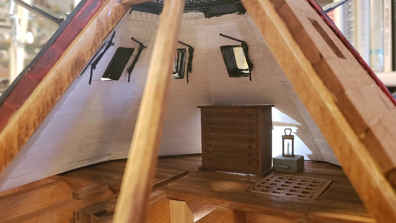
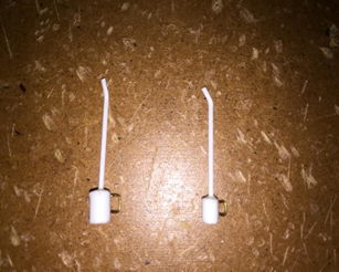
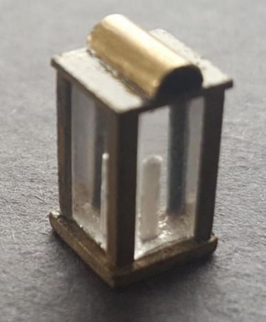
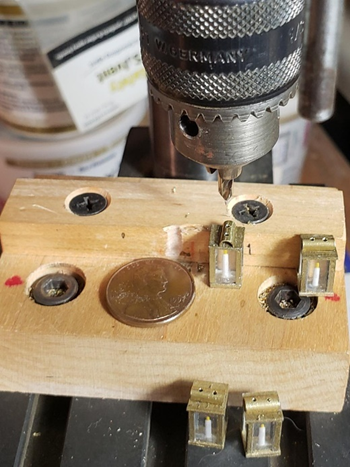
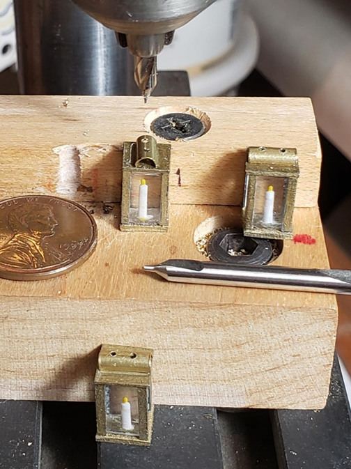
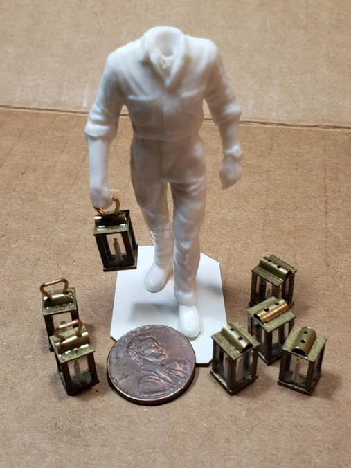
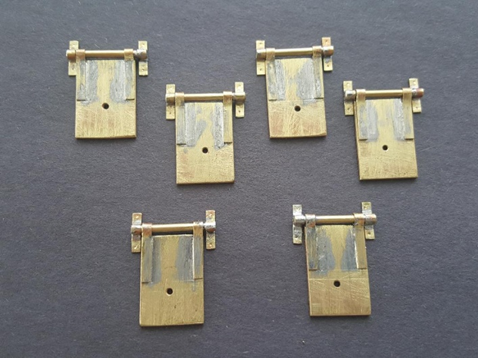
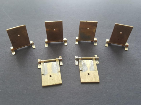
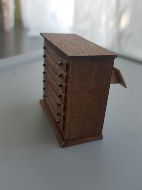
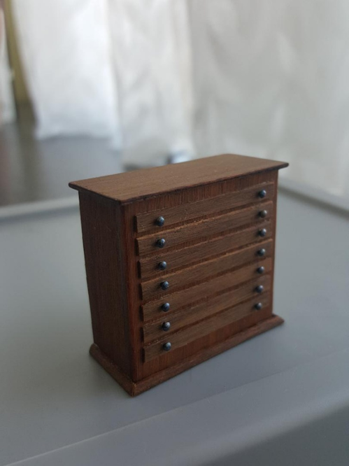
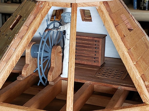
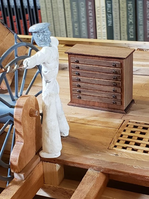
Hi all, Here's the next installment, which is from February of 2022: MAKING SMALL BRASS LANTERNS (built by Fred Hecker and Bill Kammermeyer; photos and captions by Bill unless otherwise noted) An alternative method of making the lanterns was developed by Fred using square, clear, acrylic rod as the glass. The edges were the same plastic angle with a brass tube cut in half for the vent. The bottom of the rod was drilled with a tiny bit, frosting the side of the hole-- PRESTO!, a candle! Some were “lit” by using an even smaller bit for the wick and a bit of paint on a thin wire for the flame. Great job, Fred ! FH 5/28/2021 Drilling holes in the brass lantern vent for wire bail handles was Bill's job. The use of a special bit allowed the holes to be drilled without the use of a center punched mark. This is a good view of the candles with their lit flames. these will be used in the lower working part of the engine room and storage holds. Penny for scale. BK 8/10/2021 Use of a machinist’s centering bit allowed for pilot holes to be drilled quickly without damaging the glue joints and then they could be slightly enlarged later to fit the 20-gauge brass wire used for the bails. the relatively heavy shank of this type of bit relative to its tip keeps the tip from wandering on the surface as would a standard bit. Penny for scale.. BK 8/10/2021 The 20-gauge wire handles add a touch of realism to the look and will be added to a few of the crew below deck as with the 1/24 figure that I use as a gauge for my figure sculpting. Penny for scale. Fred made a total of 21 lanterns that will be used around the "dark places" of the ship as well as in the deck storage sheds ready for night maneuvers. BK 8/11/2021 OPERATING PILOT HOUSE WINDOW ARMORED COVERS (MADE BY FRED HECKER) Operating pilot house window armored covers. 2 will be in closed position, 4 will be open and 2 will be left off of open viewing sections. Another outstanding job done by Fred. Hinge plates have been punched for Bill to drill to appropriate size for attachment pins. FH 10/13/21 MAP CASE FOR PILOT HOUE (made by Fred Hecker) When Fred Hecker sent these photos of a map chest to me, I thought it was for my approval. I thought they were pictures of an antique chest. I wondered if they would fit in the pilot house. FH 10/4/21 Fred said this was what he built. It looks so good I thought it was a photo of an antique. It looks great in place and there is still room for officer and crew as well as floor hatch use. FH/BK 10/7/21 That's all for today. Next time, also from February 2022, many many tools. Tim
-
Hi Bruce, Beautiful picture of your Whaleboat! You can be sure Vince and I will be visiting your build log for it when we start our build. Tim
-
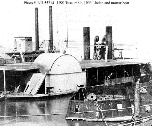
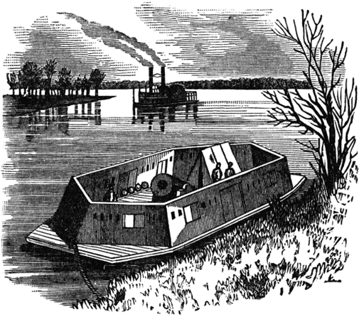
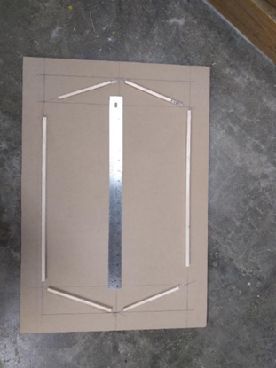
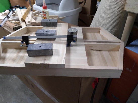
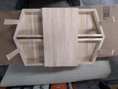
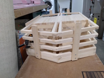
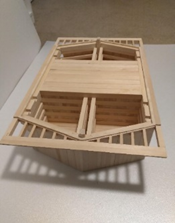
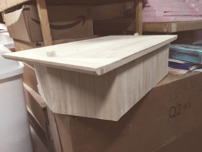
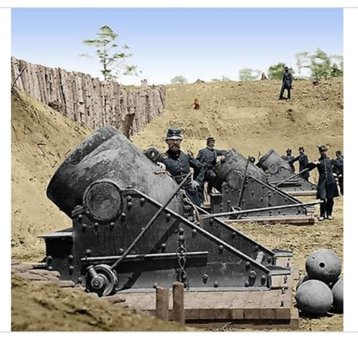
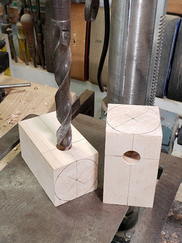
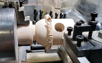
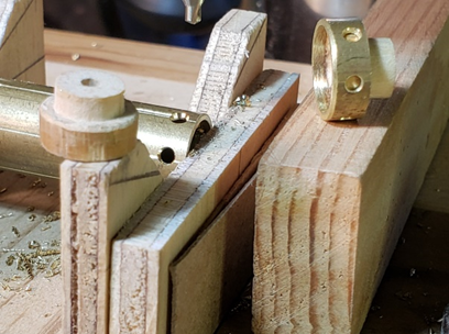
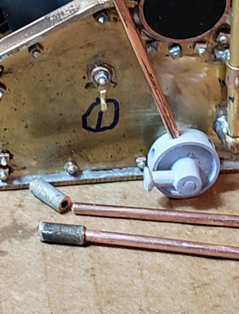
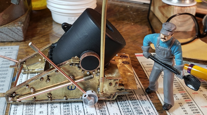
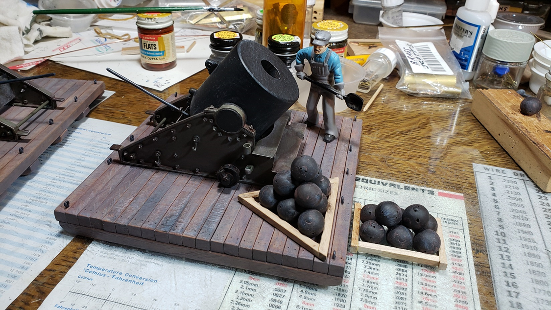
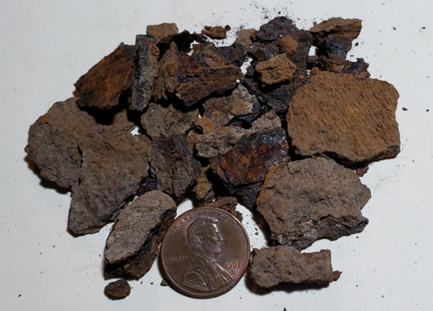
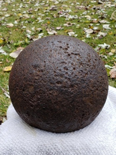
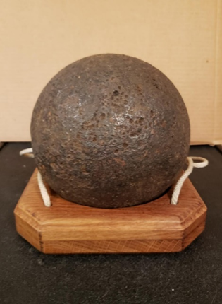
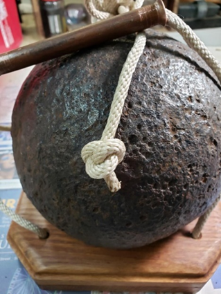
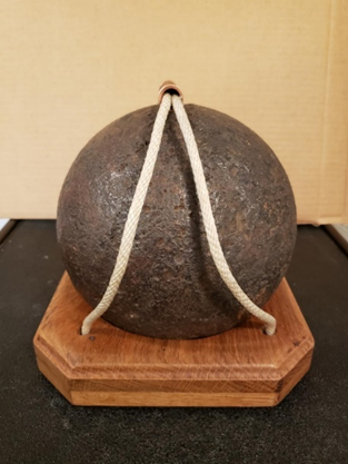
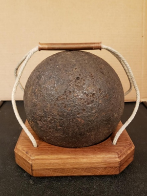
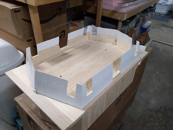
OK, now, here we go with April of 2022, which concentrates on the building of a mortar barge and the mortar itself: This month’s focus for the USS St. Louis will be on a 1/24 scale mortar barge, which is being built by Bob Keeler. The mortar itself was built by Bill Kammermeyer. These mortar barges typically accompanied larger steamships or gunboats, and has been discussed for possible inclusion in the USS St. Louis Display. MORTAR BARGE (photos and captions by Bob Keeler) The mortar barge was 45 ft long x 30 ft wide. Building at 1/24 scale gives a model that is 22.5 inches long by 15 inches wide. Mortar barges were not built for long life as you can see by condition of this barge. Civil War sketches of mortar barges were not consistent with photos and each other’s sketch configurations. Tool used to build interior structural beam layers Building the lower skin first layer of beams and start of interior cribbing which would support the mortar's weight and recoil of mortar. Looking down at the lower skin (,5 in wide by .25 thick planks), structural beams and interior cribbing made of alternate layers of .75 in x 1.00 in beams. Notice strips used to keep things aligned. View showing interior beams made up of .75 in by .75 in beams and .5 in x .5 in beams Adding the support beams for the Exterior cribbing after skinning sides and . Cribbing on mortar barges was1 foot on sides and 2 feet on ends. Model with the side skinned, the upper deck in place and the exterior cribbing. The upper deck is removable for access to the interior. One side is exposed to show interior. This is current status of model. Next step is to add supports for .04 in armor shielding. (It was 1 inch thick iron plate.) MORTAR (photos and captions by Bil Kammermeyer) As part of our build of the USS St. Louis, one of our members Bob Keeler decided to build a mortar barge in the same 1:24 scale. This non-powered raft of timbers had a 13-inch costal mortar mounted amid ship and was pushed where needed by a powered member of the fleet. I had seen these mortars at White Garden near the Battery in Charleston SC and was impressed with their squat bulk and the 200+ shell they fired over 2 miles in a big arc. I decided to build 3 scratch built models, one for Bob's barge, one for me and one for my son-in-law, Lance Carlton who lives outside Charleston and grew up on Folly Beach, the site of a lot of the action during the civil war. Just thought those who had no idea what I am building might like to see a period photo c.1863. BK I drilled hard maple blocks for the bores and trunnions. BK 4/16/21 Turned the barrels on 3 different types of lathe. BK4/23/21 I cut the carriage sides out of sheet brass as per plans that Bob obtained. BK 6/8/22 Parts were cut and soldered together. BK 6/25/21 Flash soldering required the use of a propane torch, heat sinks and clamps to join brass of different thickness without unsoldering previous joints. BK 13/27/21 Using the carriage as a guide i cut a groove for the elevating lugs on my bandsaw. BK 12/31/21 Using a horizontal jig i cut the lugs in the strip of hard Maple I had glued in the slot. BK 1/3/22 Over time I made 300+ "nuts" for the "bolts" that joined the 2 sides of the carriage half that clamped the "t" strip around the edges of the carriage half. BK 1/5/22 The mounting hardware for the loading cranes as well as the cranes (gibbets) themselves were made. Penny for scale. BK 1/9/22 Parts of the cranes as sub assemblies (7 parts for each crane) soldered together. BK 1/9/22. The front loading steps we're soldered to brass angle using a spacing jig. The full crane is in place and functional. BK 1/11/22 The triplets are moving right along. It is a constant situation of fit and file. BK 1/12/22 The small wheels on the side and the internal cam operated by the tube on the axle allowed the wheels to lift and hold the 8 tons of mortar and carriage a fraction of an inch and then with iron rods in the wheel holes, rotate the mortar left or right. Penny for scale. BK 1/23/22 Making the cam sockets required soldering small brass rings to the ends of small brass tubes. Penny for scale. BK 2/23/22 Using an indexing jig I drilled 6 equidistant holes in a half inch brass tube. I inserted a wheel that I had turned to the exact internal dimensions of the tube to form the cam section of the wheel in the cut ring of drilled brass. BK 1/22/22 All the wheel parts were permanently attached to the axle and bars were made to switch the cam mechanism as well as turn the wheels. All parts were primed before painting. BK 1/25/22 All of the parts had to be finished and attached on the right side and free and open on the left side so I could pull the carriage sides apart and insert the cannon barrel. I did this due to the strange size and configuration of the cap squares that cover the trunnions on the cannon. I will never do this again. In retrospect the significant amount of time and effort needed to make the 2 sets of steel jigs for the cradles and cap squares would have been well worth it. BK 2/27/22 Since only one of the mortars will be in a mortar barge the other 2 will be on a hard surface platform. As per period photos I built 2, scale 12' x 12' heavy timber platform with heavy skids. I then tried different methods to show the use of the crane, 200 lb. shells and tools needed to load and service the mortar. BK 2/12/22 MORE TO FOLLOW Extra Added Bonus! Bill’s very own CIVIL WAR CANNONBLL!!! (pictures and text by Bill) As I was leaving a garage sale with my 50 cent purchase I noticed a small dark object at the corner of the driveway and the street. It was convex and about 4 inches in diameter. I asked the homeowner if it was a cannon ball and he said "That's what the guy who gave it to me said". I asked if he wanted to sell it for $5 and he said yes. I borrowed a shovel and kept hitting iron as I worked outward. the ball was much bigger than I thought and I needed help getting it out of the now 10 inch hole filled with wet mud and slick leaves. I just could not grip it with my finger tips. Turns out that it was not only wet and slick but weighed 65 pounds. It was a shot for an 8 inch Civil War cannon. Oddly enough the 3 largest cannons on the USS St. Louis that I am building at 1:24 scale happen to this same gun. This 65 pound hunk of iron could be fired over 2 miles with devastating effects to fortifications and troops, and was! The ball was heavily rusted and large flakes of scale from about the size of pinheads to that of quarters distorted its shape. (Penny for scale, no pun intended). After about 3 hours of chipping with a brick hammer at the scale I was able to remove most of it. A steel cup brush on an angle grinder removed the rest of the flakes. After rinsing it with water, this is its current condition. I have no idea how long it was in the ground or its origin other than the fact that they were stored aboard the City Class gunboats built in Carondelet, south St. Louis and Mound City, and were fired at fortifications in mass south of St Louis. BK 11 / 1 / 21 To be able to more easily move and store my treasure, I built a carrier of white oak boards, which were cut, glued and screwed together at cross grain with a tapering hole in the center. The ball rests securely in the pocket and stays where I put it. Holes were drilled through both boards at the corners, with the bottom hole being enlarged to hold the knot for the ends of the nylon rope handles. A piece of copper tubing was flared at the ends and used as a handle with both ropes passing through it to comfort the hand while lifting the 65 pounds. It is great fun watching the reaction of friends and family as they give this relatively small sphere a lift. One-inch, rotating casters were screwed to the bottom for easy movement. It is a lot easier to roll it than lift it. It is a neat conversation piece and I am pretty sure I am the only guy on the block that has one, BK 12/12/22 Hope you have enjoyed this little tangent. Back to the USS St. Louis proper in the next installment, which will look at all manner of things, such as lanterns, multiple tools and ceramic jugs. Tim