gak1965
-
Posts
698 -
Joined
-
Last visited
3 Followers


Recent Profile Visitors
2,546 profile views


-
 gak1965 reacted to a post in a topic:
Flying Fish by Jared - Model Shipways - 1:96
gak1965 reacted to a post in a topic:
Flying Fish by Jared - Model Shipways - 1:96
-
gak1965 reacted to a post in a topic:
Flying Fish by Jared - Model Shipways - 1:96
-
J11 reacted to a post in a topic:
USS Kearsarge by gak1965 - BlueJacket Shipcrafters - 1:96
-
J11 reacted to a post in a topic:
USS Kearsarge by gak1965 - BlueJacket Shipcrafters - 1:96
-
J11 reacted to a post in a topic:
USS Kearsarge by gak1965 - BlueJacket Shipcrafters - 1:96
-
J11 reacted to a post in a topic:
USS Kearsarge by gak1965 - BlueJacket Shipcrafters - 1:96
-
J11 reacted to a post in a topic:
USS Kearsarge by gak1965 - BlueJacket Shipcrafters - 1:96
-
J11 reacted to a post in a topic:
USS Kearsarge by gak1965 - BlueJacket Shipcrafters - 1:96
-
J11 reacted to a post in a topic:
USS Kearsarge by gak1965 - BlueJacket Shipcrafters - 1:96
-
J11 reacted to a post in a topic:
USS Kearsarge by gak1965 - BlueJacket Shipcrafters - 1:96
-
J11 reacted to a post in a topic:
USS Kearsarge by gak1965 - BlueJacket Shipcrafters - 1:96
-
J11 reacted to a post in a topic:
USS Kearsarge by gak1965 - BlueJacket Shipcrafters - 1:96
-

Bulwark Posts
gak1965 replied to Jackie's topic in Building, Framing, Planking and plating a ships hull and deck
I assume you are going to put some bulwark planks on, correct? If so, put on the planks and Dremel the down to size once you are done. The extra adhesive on the planks will keep the from flying off. I've done that before with good success. Regards, George -
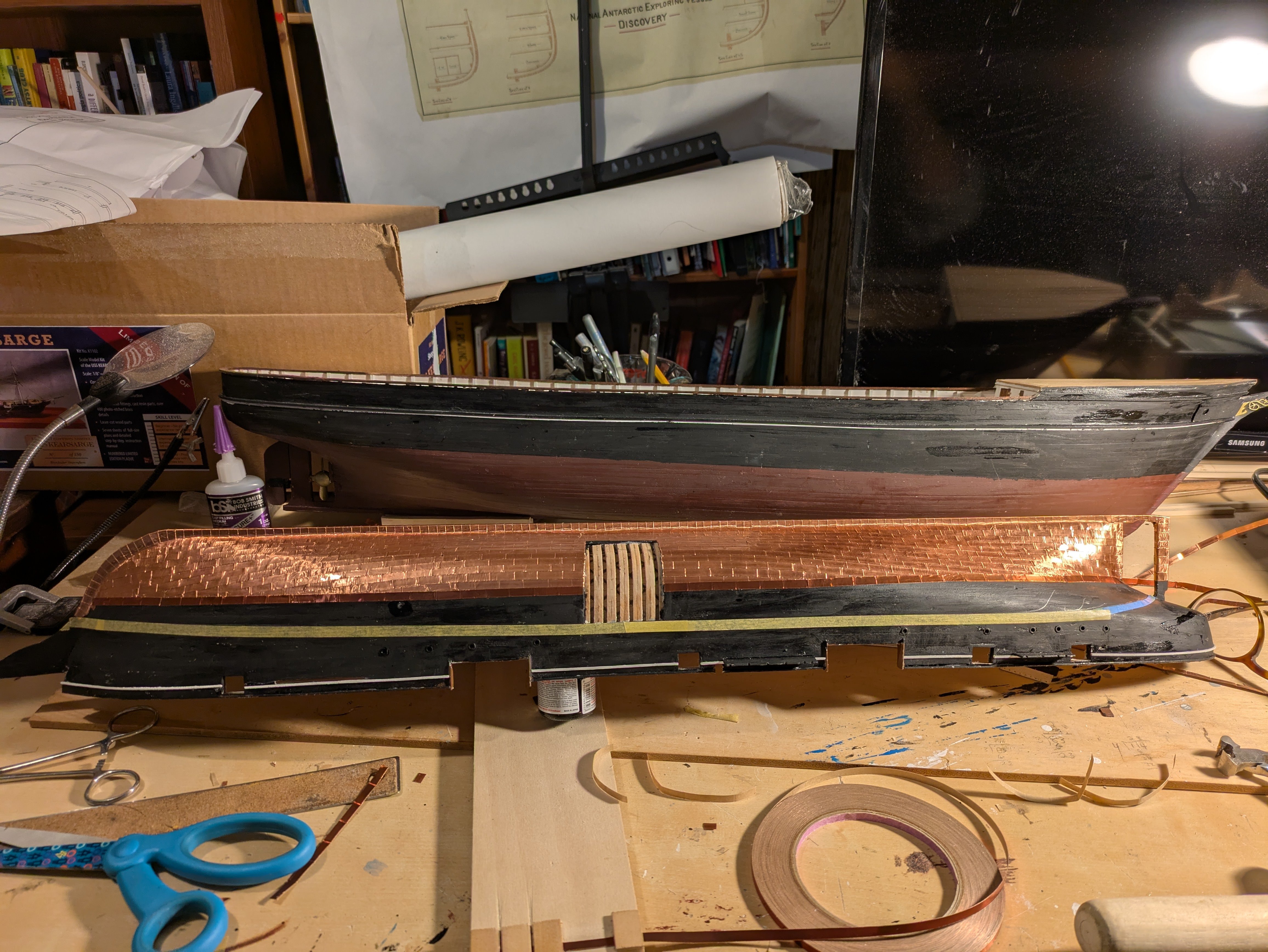
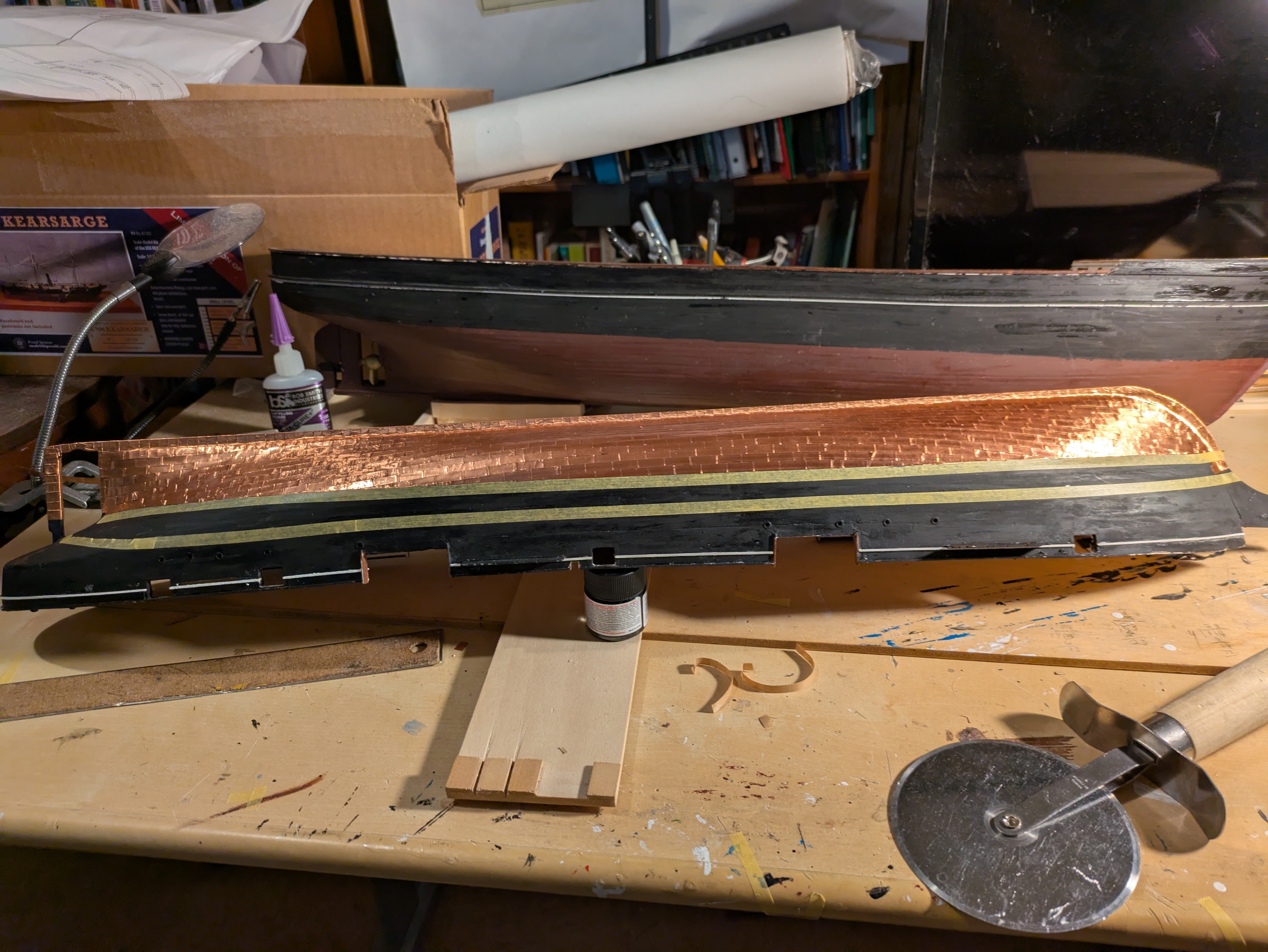
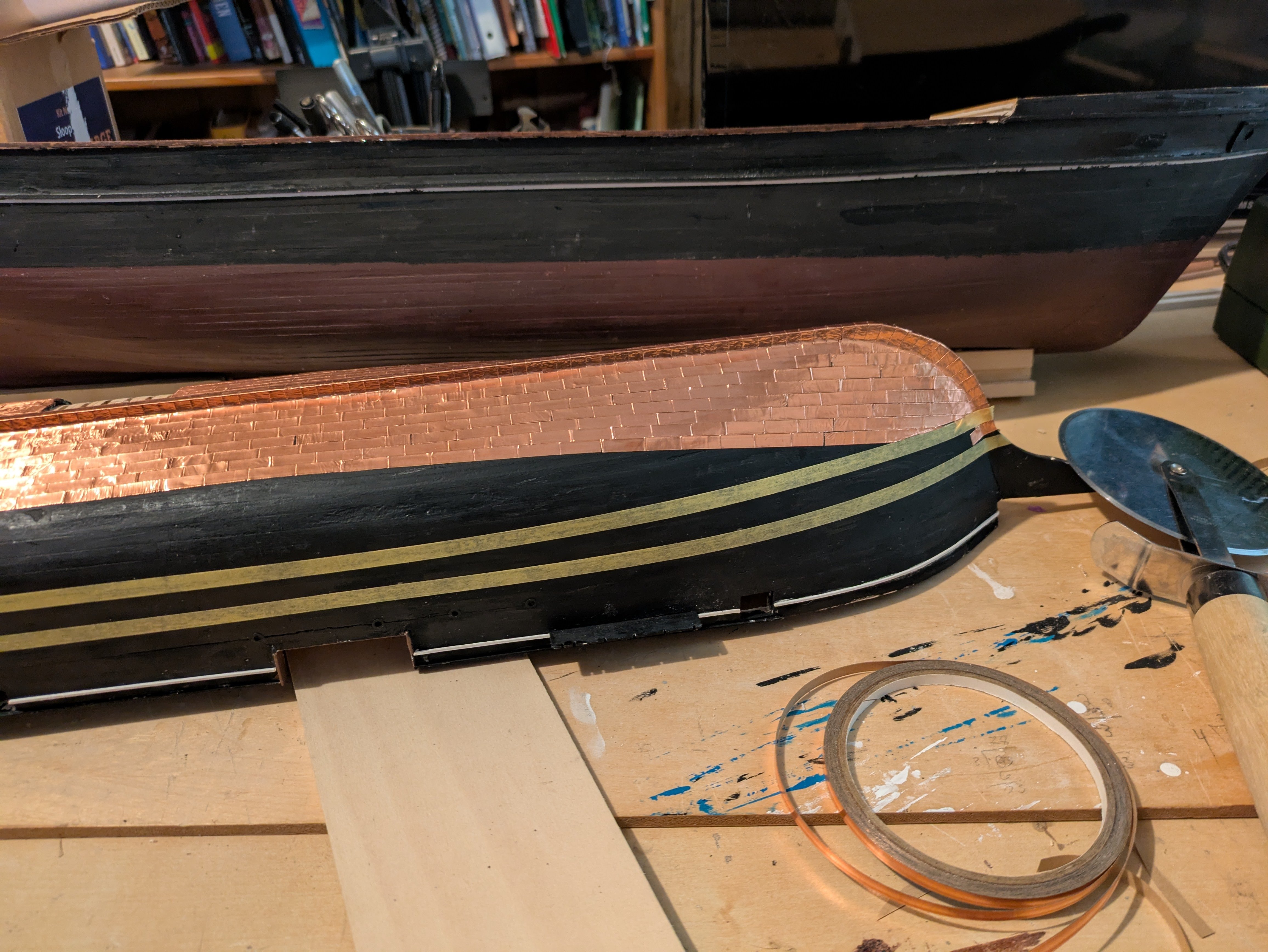
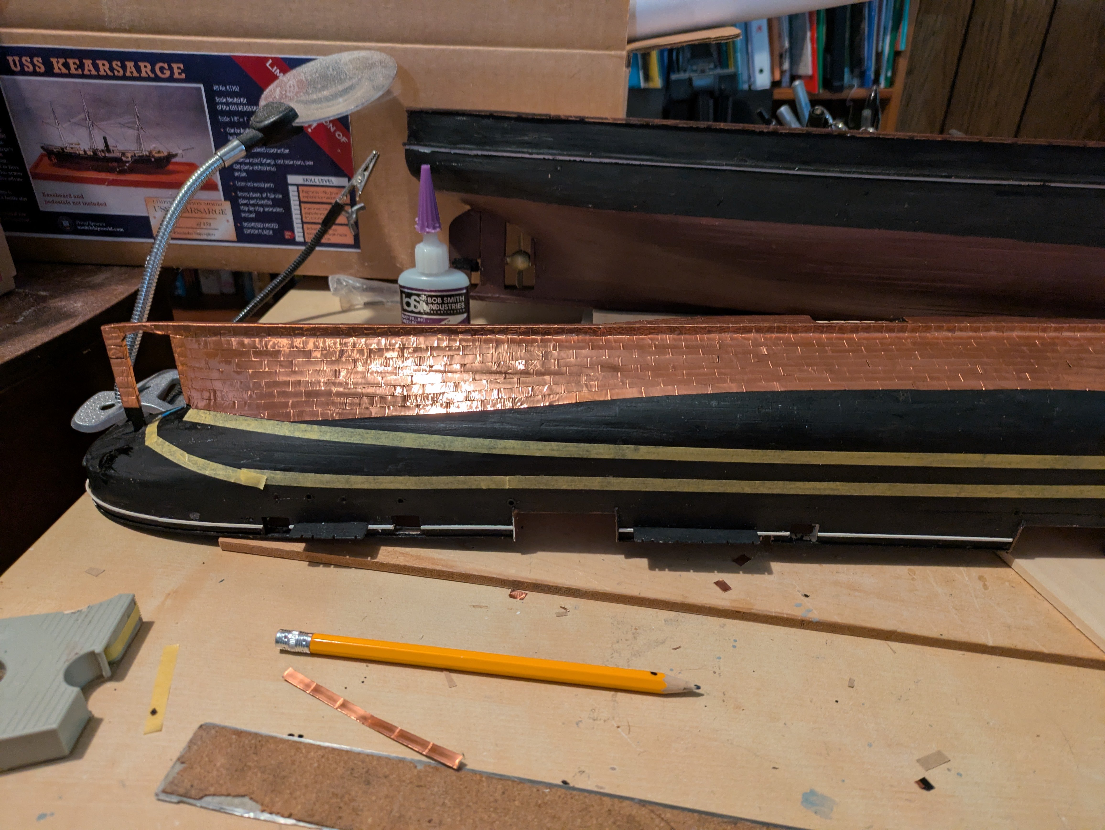
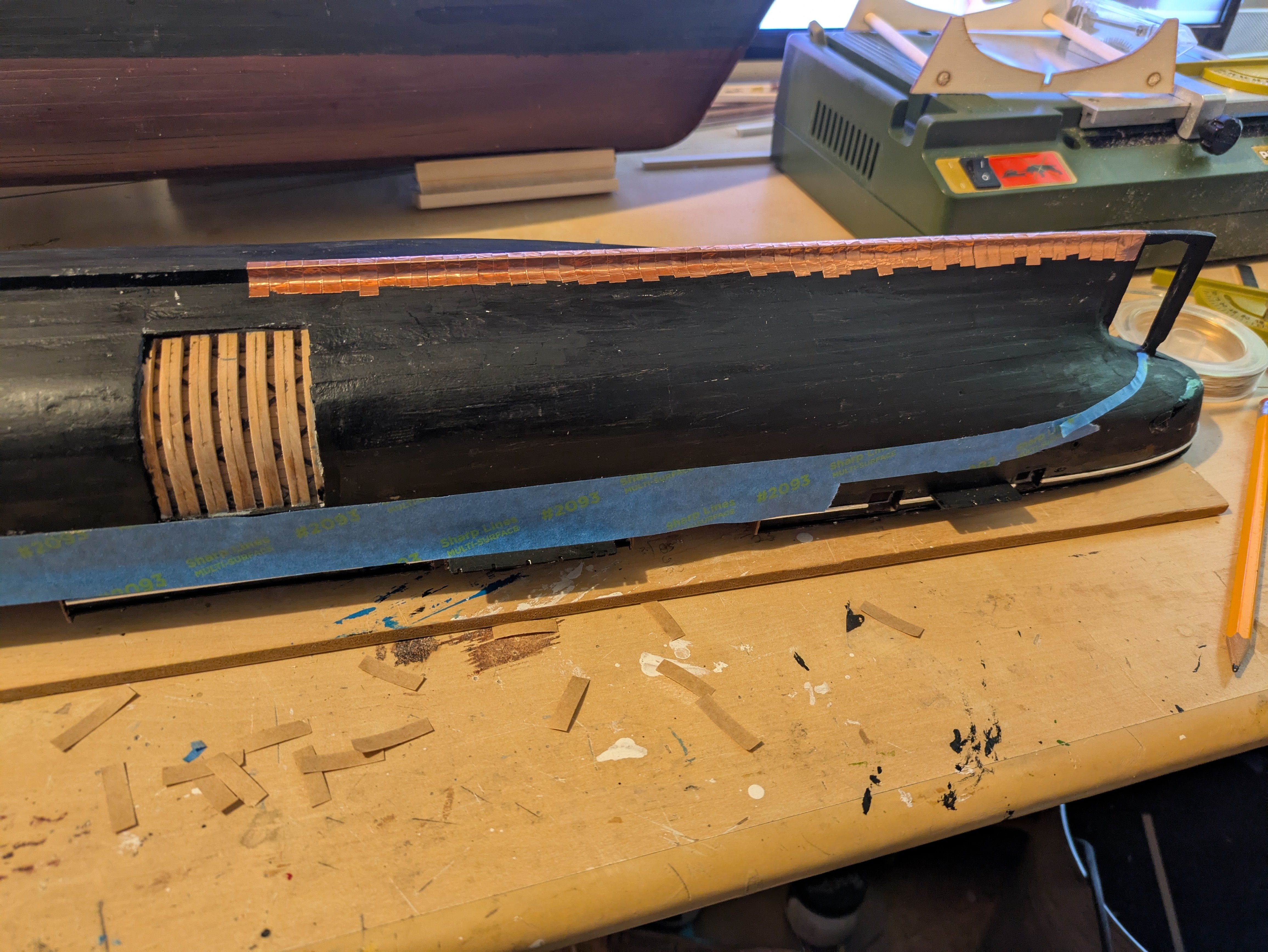
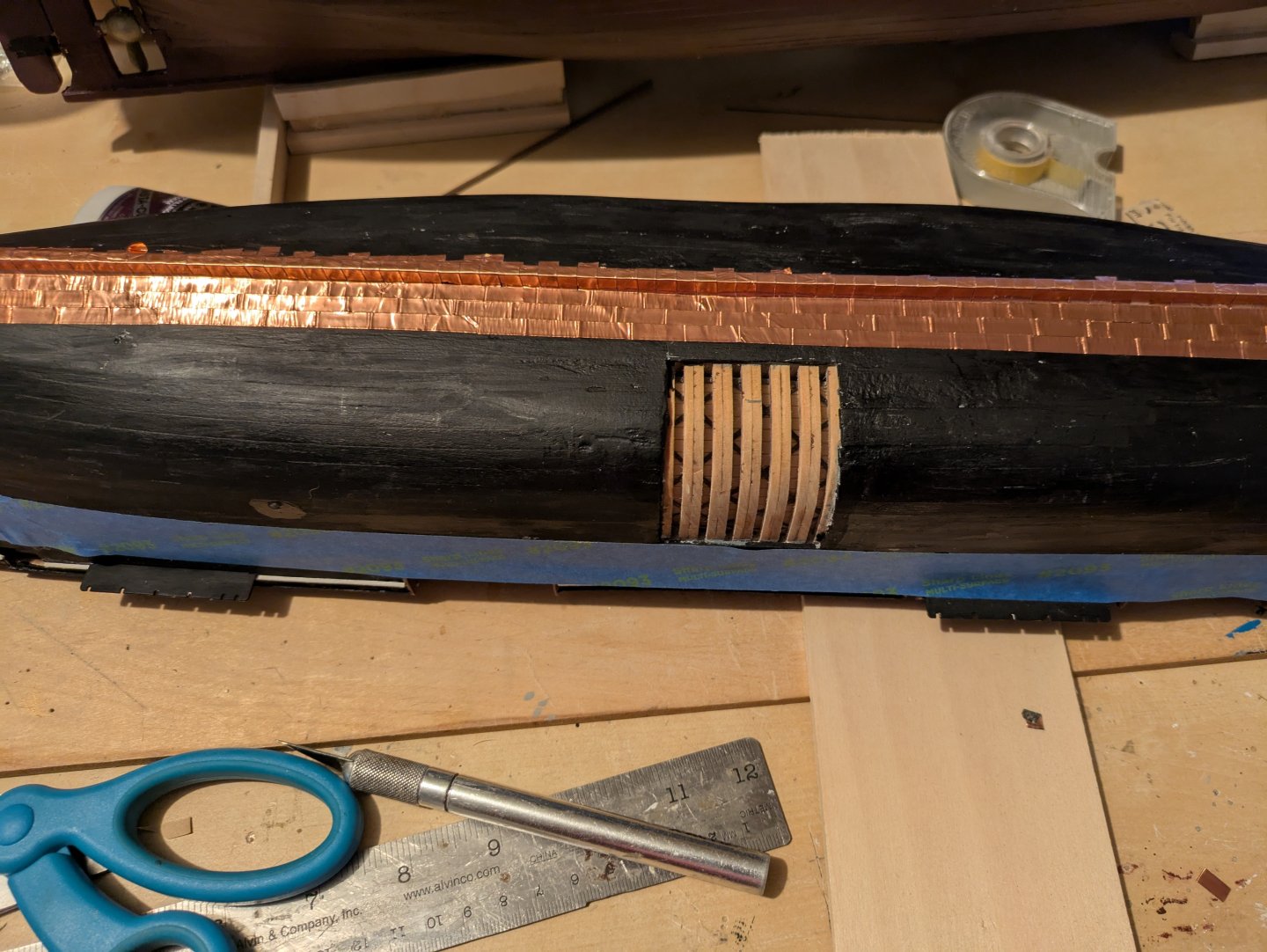
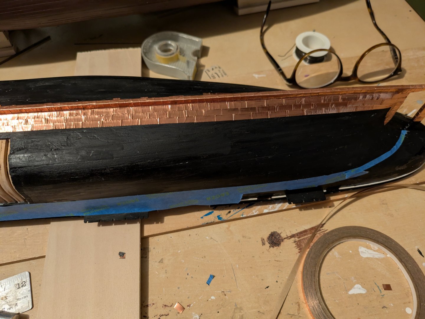
Copper plating continues. The first picture shows the plating before I was really reaching the gore line: As the plating was "bending" up at the stem and stern, it was terminated at the tape marked gore line, where I will start a new row of plating that is more in line with the final waterline. Here it is at the stern: and the stem: The next two show the plates up to the gore line with the tape still in place: And removed Finally, here is the first of the plates above the gore line: One thing that surprised me was that I started a new roll of Venture tape when I went to the gore line and it seems a bit redder to me. I doubt that it will matter once it tarnishes a bit, but it was still a surprise. Fortunately, I ran out of the old roll just as I finished both sides below the gore line, so it will at least be consistent. If it really starts bothering me, I can hit it with some copper paint, but, like I said, my guess is once it starts tarnishing it won't be very obvious. Regards, George


-
Looking great, Jared!
-
gak1965 reacted to a post in a topic:
Flying Fish by Jared - Model Shipways - 1:96
-
gak1965 reacted to a post in a topic:
Lancha Chilota by JacquesCousteau – Scale 1:32 – Chilean Coasting Sloop
-
gak1965 reacted to a post in a topic:
Libertad 1925 by Valeriy V - Scale 1:100 - Spanish Type F Light Cruiser
-
gak1965 reacted to a post in a topic:
RRS Discovery 1901 by gak1965 - 1:72 - First Scratch Build
-
gak1965 reacted to a post in a topic:
RRS Discovery 1901 by gak1965 - 1:72 - First Scratch Build
-
gak1965 reacted to a post in a topic:
Endurance by Tomculb - OcCre - 1:70
-
Jared, Is it only the forestays, or are you seeing other stays sag a bit as well? If it's just the forestays, did something happen to the bowsprit or the dolphin striker? That seems more likely than the foremast starting to bend forward to any degree.
-
gak1965 reacted to a post in a topic:
USS Kearsarge by gak1965 - BlueJacket Shipcrafters - 1:96
-
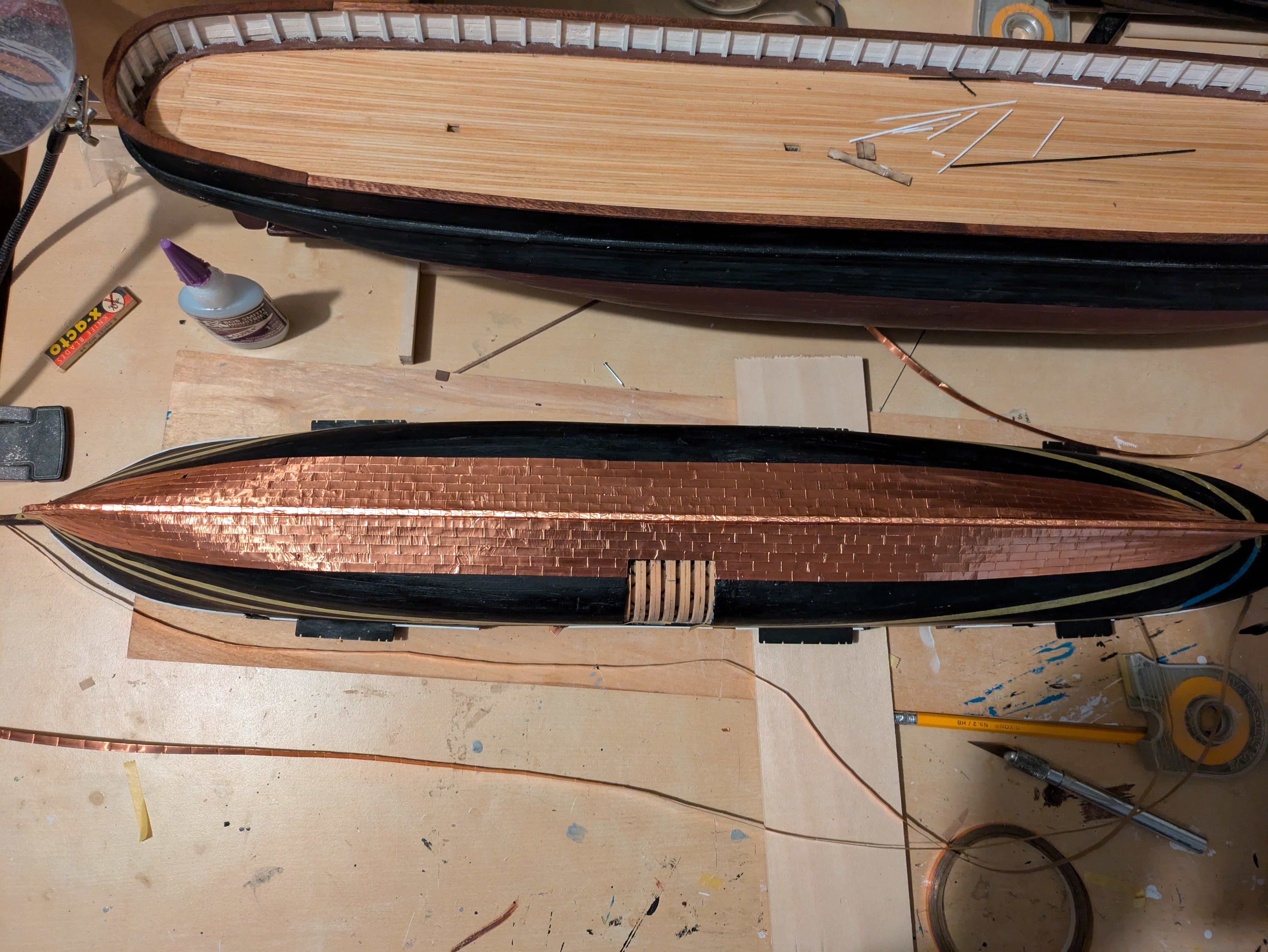
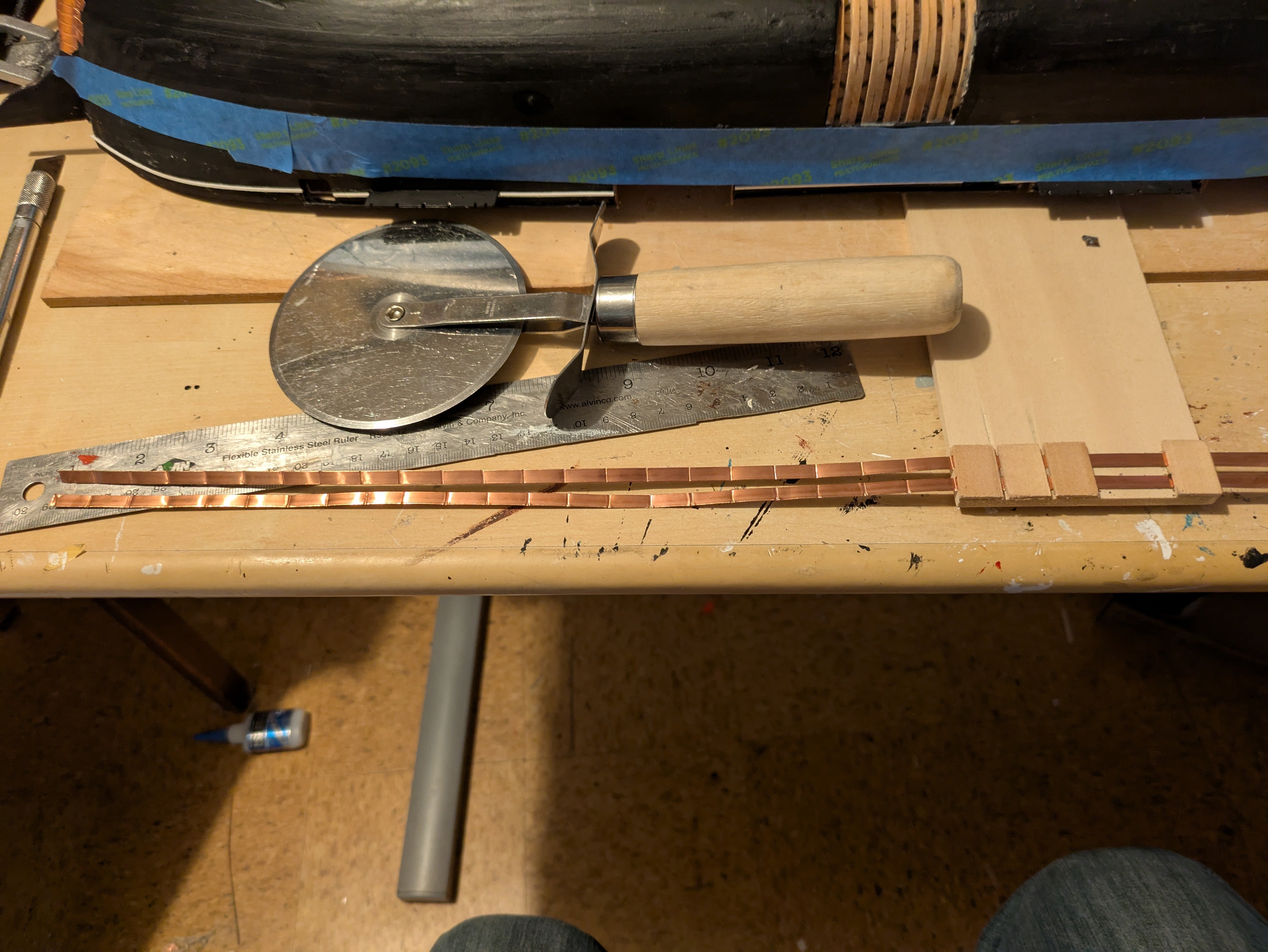
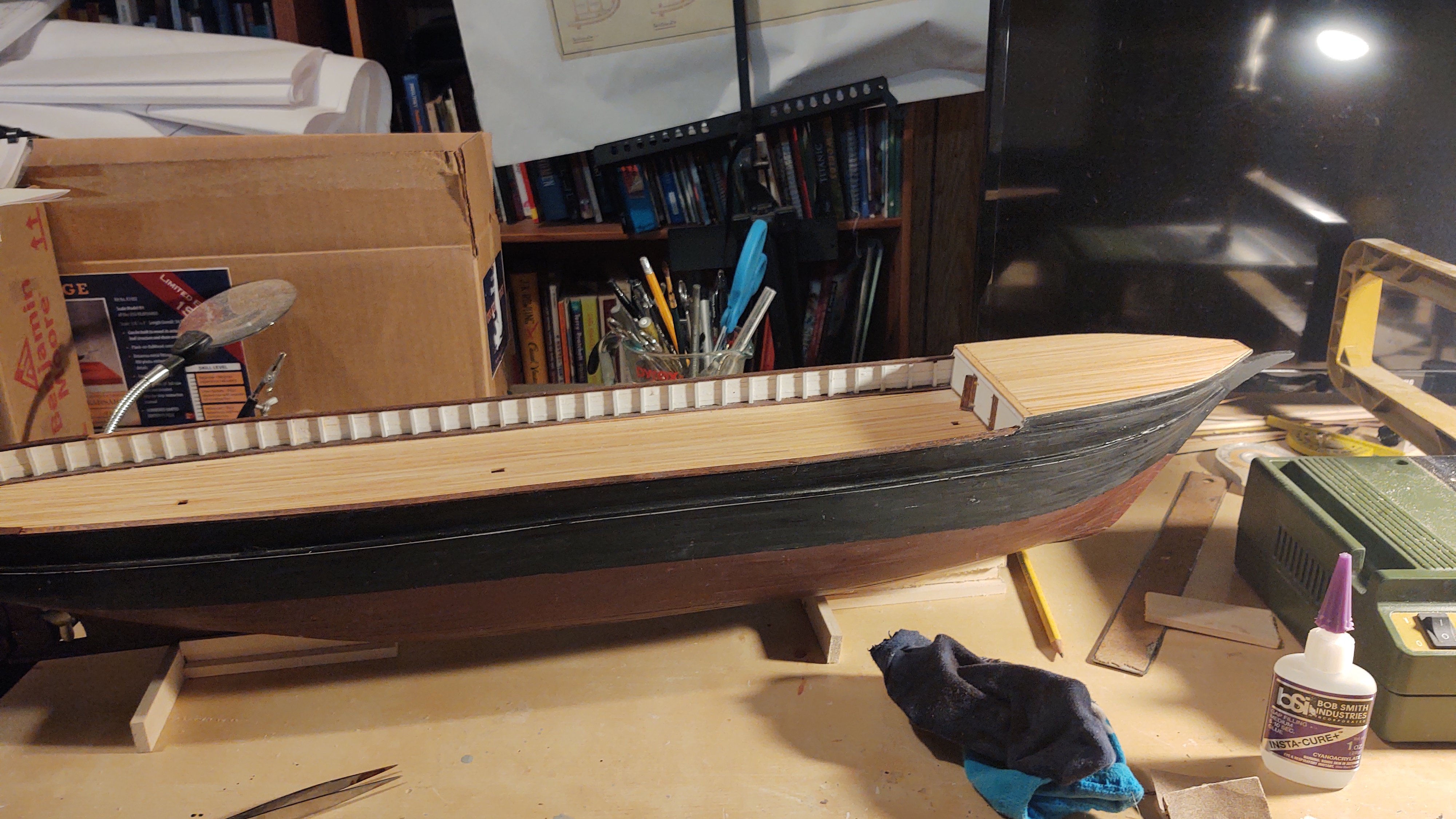
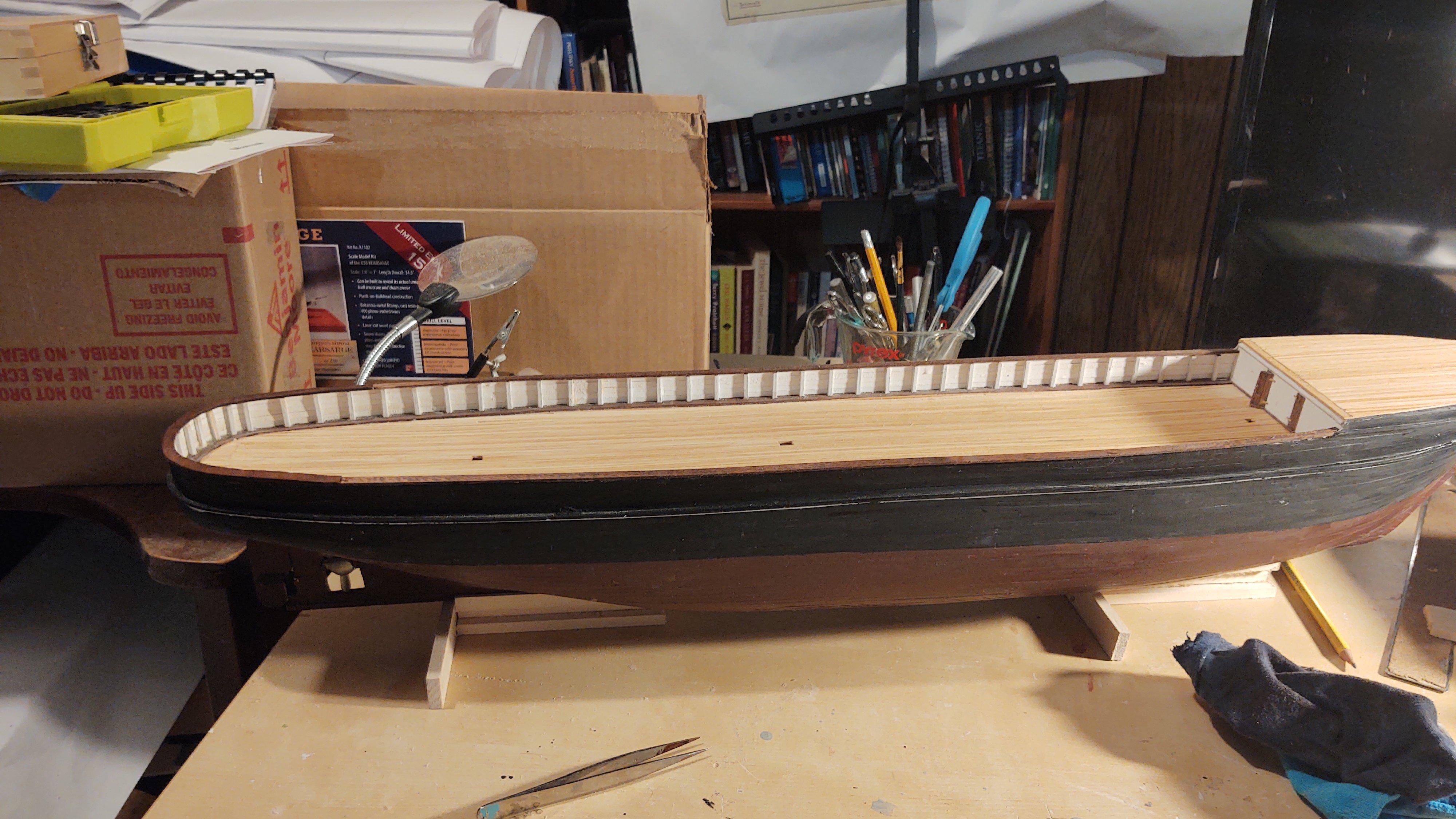
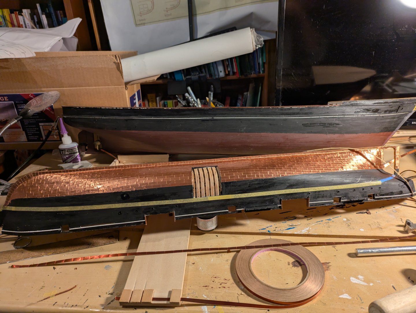
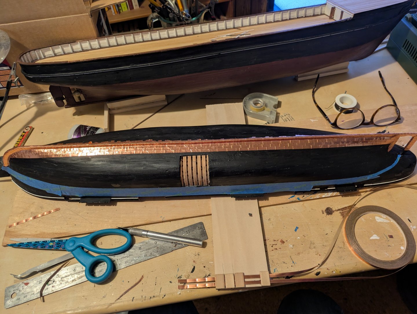
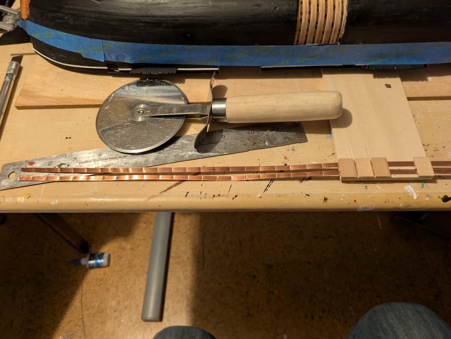
Okay, it's been a couple of months where I've been mostly focused on the Discovery. Here she is now, including the bow decoration which was a royal pain to make: So, back to the Kearsarge for a bit. As I indicated above, next is going to be the copper plating, after which, I can mount on a build board. I like to use 3/16 venture tape, which is now discontinued, for making plates at 1:96 scale. I also like to make them about 1/2" long, which translates to a 18" by 48" plate in real life. The Flying Fish called for 14" high plates, looking at some of the ones on the Constitution makes me thank that this is close enough. So, step 1 is to put copper tape on the keel and at the stem and stern to sort of frame the bulk of the copper work. I have a batch of 1/4" Venture tape that I used for that. Obviously I wasn't going for precision, but it won't matter, because, except on the actual keel, it will be covered by the rows of plates. The blue tape marks the point where I will stop coppering. Next, here is my plate making apparatus, which I kept from the Fish. I run two sets of tape through the jig, use the pizza cutter to score along the two gaps on the left. Then I move the tapes so that the new scores are even with the left side of the jig and repeat. I tend to cut the strips into 6 plate sections, as anything larger can be difficult to work with. I use the adhesive from the tape to attach it to the hull, but don't bother with nail marks, which would be pretty much invisible at this scale. Instead I let the imperfections in the tape suggest the surface (including the nails). Here is the first few rows on the starboard side. First, overall, with the Disco in the background: And two closer looks: I wasn't sure how it was going to lay on the hull, but if you look at the bow you will see that the natural flow has a definite "upsweep". I expected as much, so will be laying down a bit of tape to mark a gore line. Basically, I'll run the tape up to the gore line and then restart the plates in a flatter arc. I'll point it out when I get there. Thanks for looking in! Regards, George


-
Hi Jared, Glad you had a good time in Costa Rica. When you say that some of the lines are starting to sag, can you be a bit more specific? Are you concerned about the bit of slack in the tackles that are connecting the lifts with the deck or other lines, and if so, are we talking mostly standing or running? I found that I got a bit of slack in the tackles as well. Part of the problem (I think) is that the stress on the lines was bending the yards slightly up, which caused a bit of slack in the tackles. The crane on the model was made of brass, not iron and so bent more easily than on the real ship. In a couple of cases, it got loose enough that I was able to do a wrap on one of the belaying pins, but I mostly just ignored it. No one else noticed, and real ships tend to not have running lines that are extremely taut when they don't have sails. Regards, George
-
gak1965 reacted to a post in a topic:
USS Cape (MSI-2) by Dr PR - 1:48 - Inshore Minesweeper
-
It took more than a little bit of futzing around, but I tried @Javelin's idea of using wire, in this case, primarily 24 gauge annealed steel wire. The hardest part was actually making two sets of the wires. However, here it is, mounted on the ship: It's not exactly the same as the real ship, but it is much better. Regards, George

-
Getting really close there, Jared! Regards, George
- 342 replies
-
- 1
-
-
- Flying Fish
- Model Shipways
- (and 1 more)
-
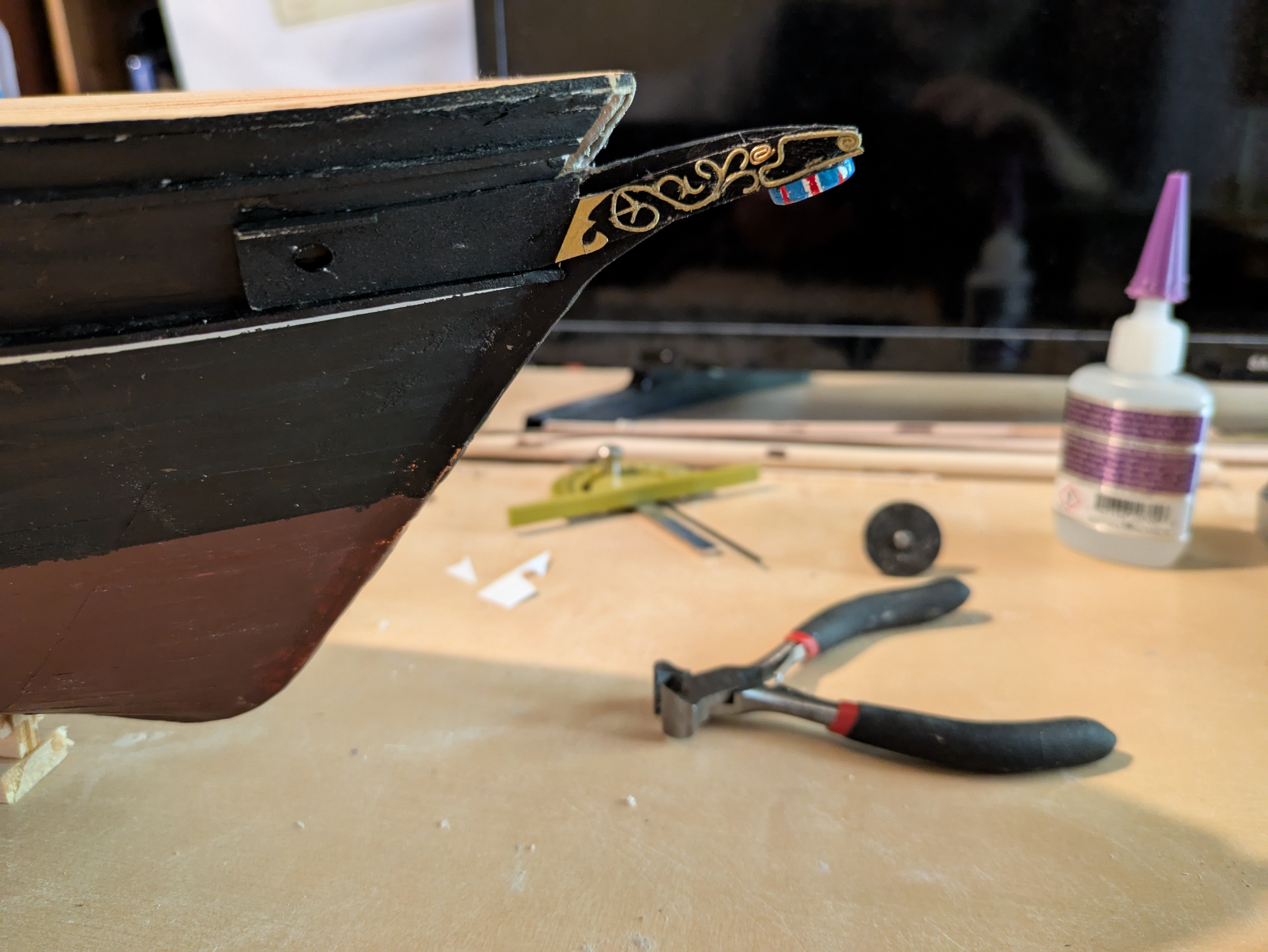
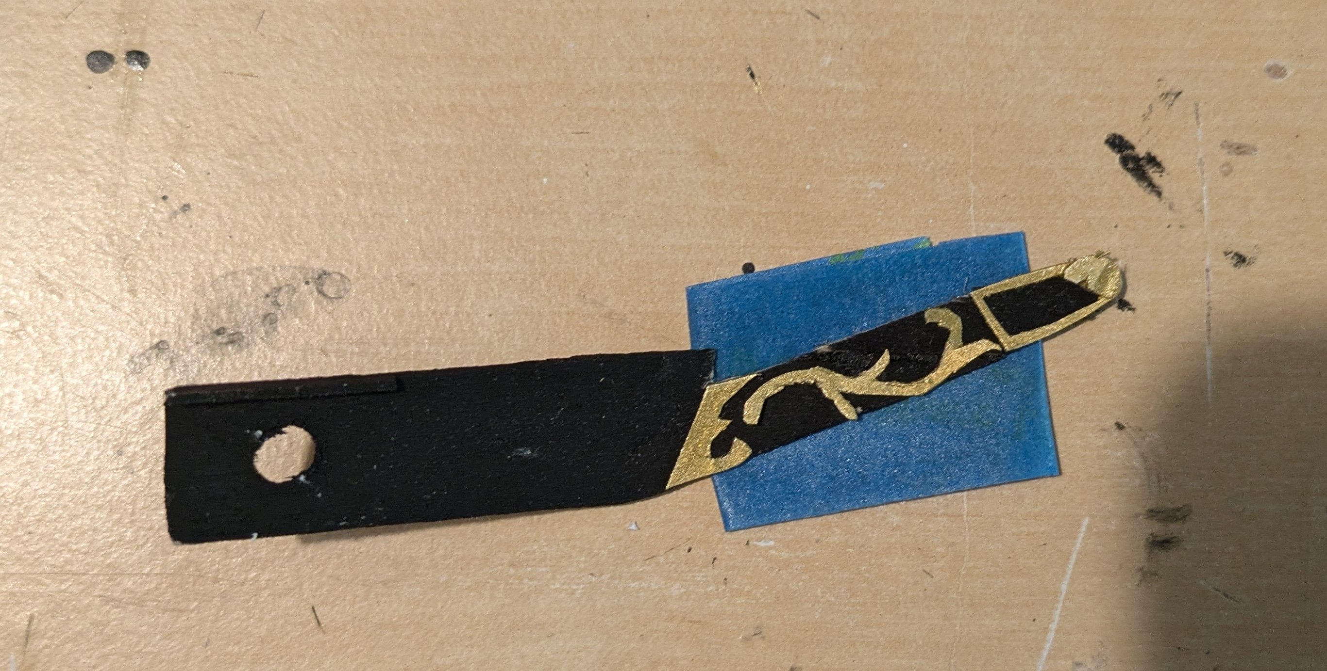
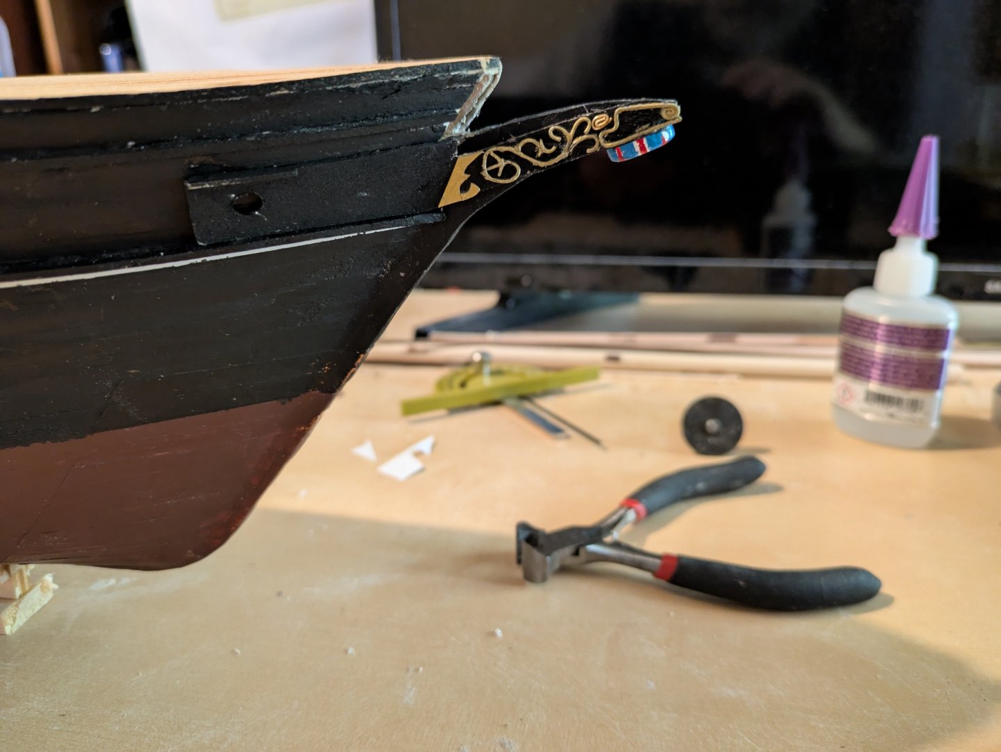
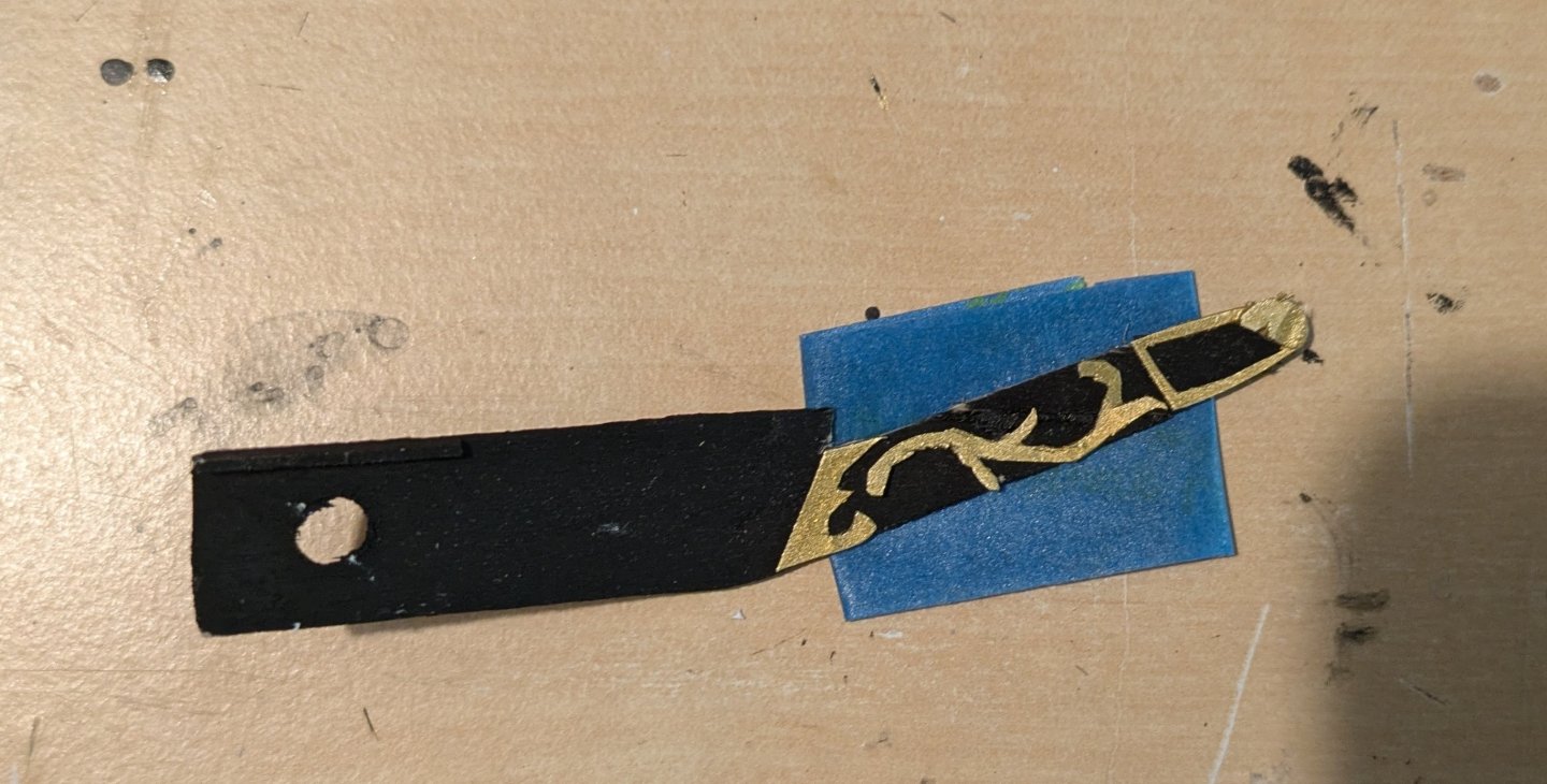
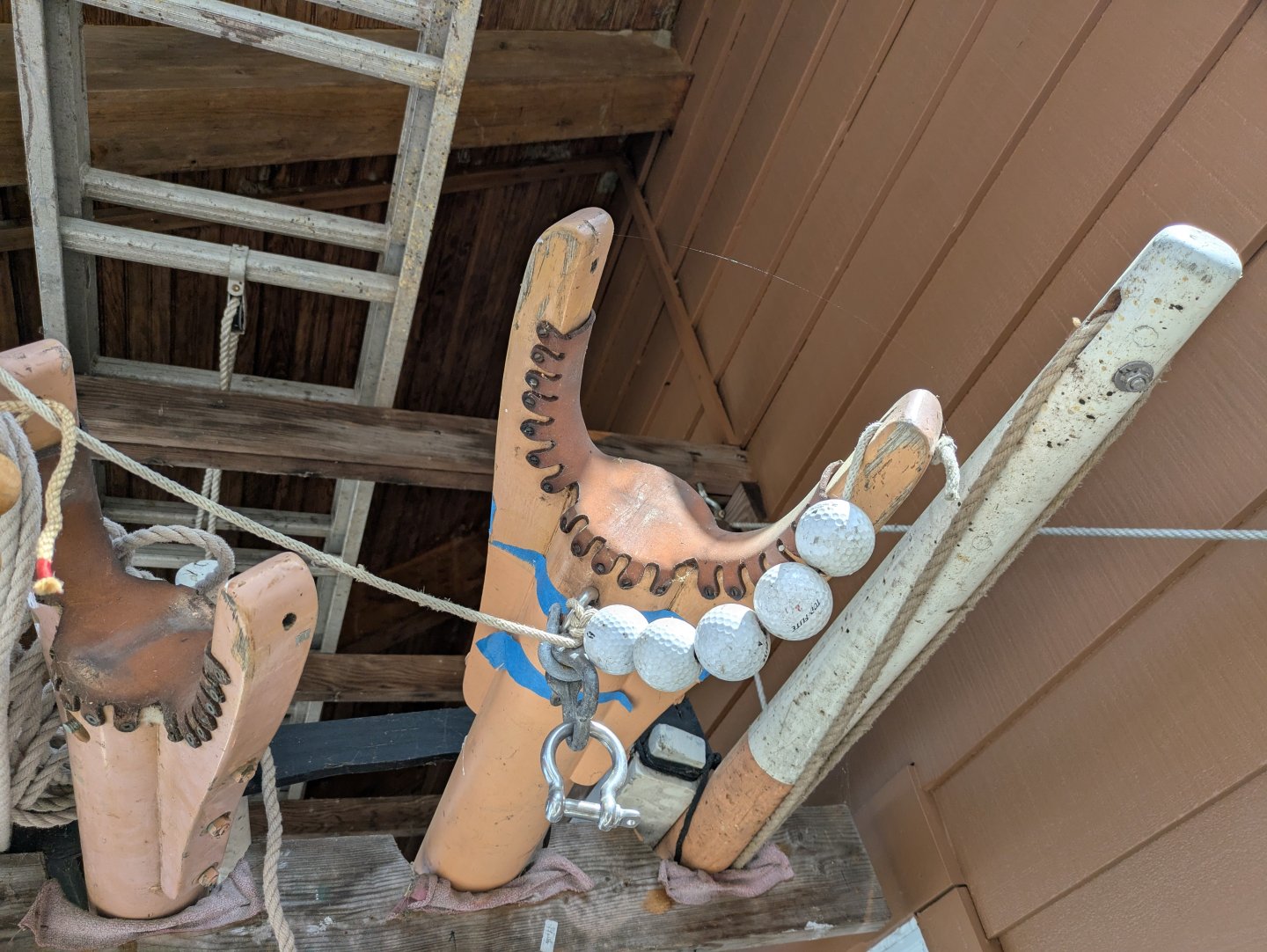
Thanks @iMustBeCrazy, @Lecrenb, and @Kevin-the-lubber, thank you for the suggestions! I tried using card, but I found it tore too easily. Maybe my blades aren't sharp enough, but it didn't work. And unfortunately, I don't have access to a 3D printer or an entity that will make a brass copy alas... However, I then returned to a thinner piece of polystyrene, and was able to make something that, I think works...? (the pieces are not glued on yet, they are just sitting there to see how they look). It's not perfect, it's probably as good as I'm going to get at this scale. I also made the shield that is the figurehead on the ship. It's not perfect, but it is probably as good as I'm going to get. Anyway, I need to make a duplicate of the scrollwork for the port side, and then I can mount on the ship. On a more amusing note. My wife and I teach math to apprentice shipwrights at the Alexandria Seaport Foundation, and when I was there, I noticed two gaffs being stored on the roof. At the jaws of one, there were standard wooden parrel beads. On the other, were these rather atypical ones: Waste not, want not, I suppose. As always, thanks for looking in! Regards, George
-
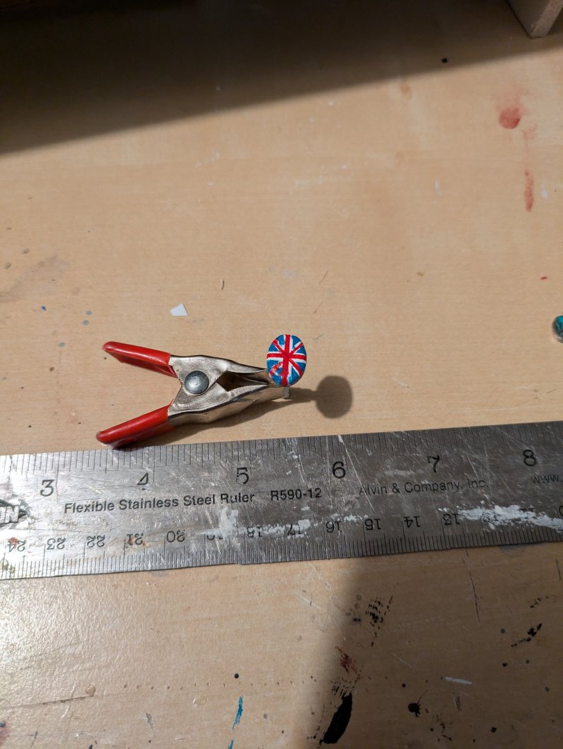
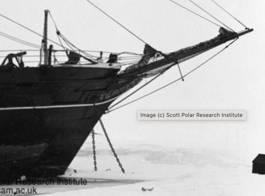
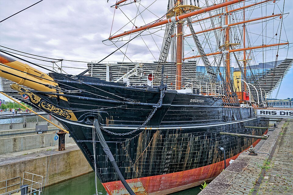
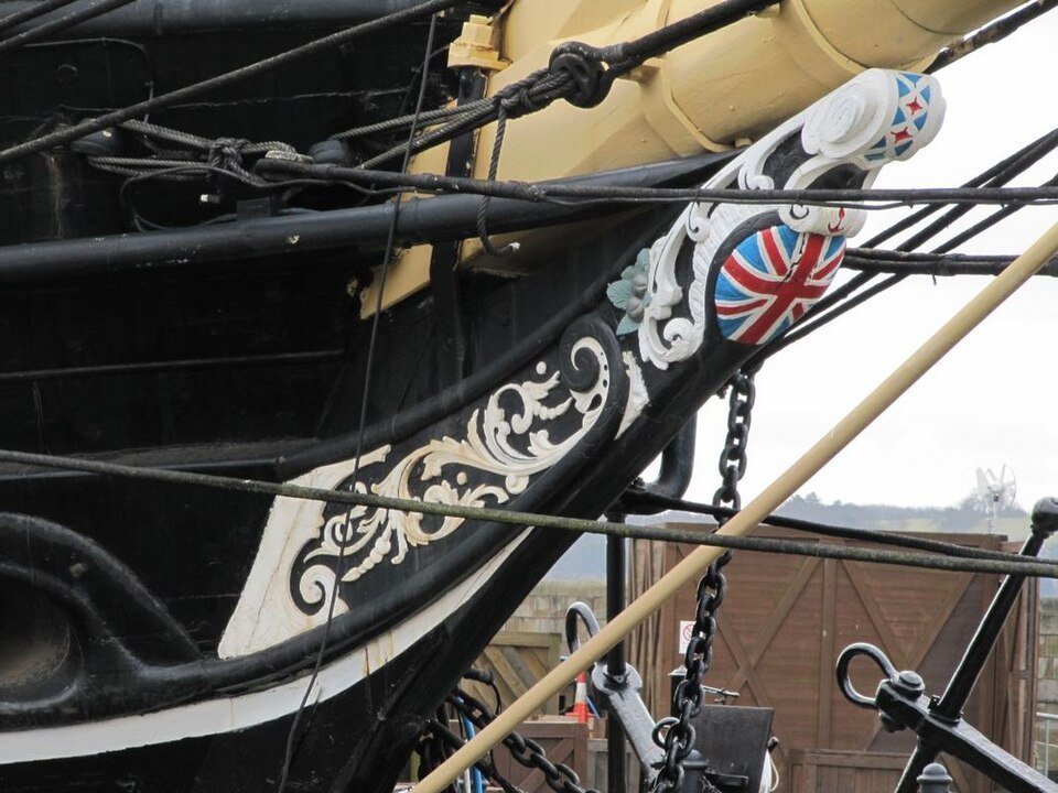
Thanks Rick. Let's just say it took more than one try and leave it at that! I've been working on the stem now. I had earlier cut and bent two pieces of wood that would represent the naval hoods (?) which have the hawse holes and the scrollwork on the stem. Drilling the hawse holes was easy, I've been working on the scrollwork which is much harder. Here is the ship stuck in the ice in 1901, you can see the scrollwork (probably gilded since it is a different color than the white stripe). Here is the ship in 2010 with (nominally) the original bow: Here is the ship today with a replacement (nominally identical) bow (licensed CC-BY at https://commons.wikimedia.org/wiki/File:1901_wurde_die_RRS_Discovery_in_Dundee_vom_Stapel_gelassen._02.jpg: The scrollwork is, to say the least, complex. My original thought was to simplify somewhat, cut it out from 1/32" thick bass, sand the edges, paint them, and mount onto the naval hoods (or whatever the correct terminology is). However, I have found that I can't cut even a simplified version out of 1/32" bass, the things just break (repeatedly). I've tried cutting things out from polystyrene sheet. This seems more promising, but getting something that doesn't look like it was done by a child has proven complicated. Any thoughts on this? I've looked at some of the carving tutorials on the site, but they seem more focused on taking pre-cut items and carving them to be more three dimensional. Are there other materials I should be thinking about? I know that I'm going to have to simplify it given the scale, but so far my best attempts have looked simplistic at best. Anyway, appreciate any insights anyone might have. Regards, George PS - The Union Jack is going to be made separately.
-
Jared, She's really looking fantastic! Glad you took the time you needed, and are ready to proceed apace. Regards, George
-
Hello! I am also George from Washington, DC (well, Rockville a bit north of you). Welcome to MSW! George
-
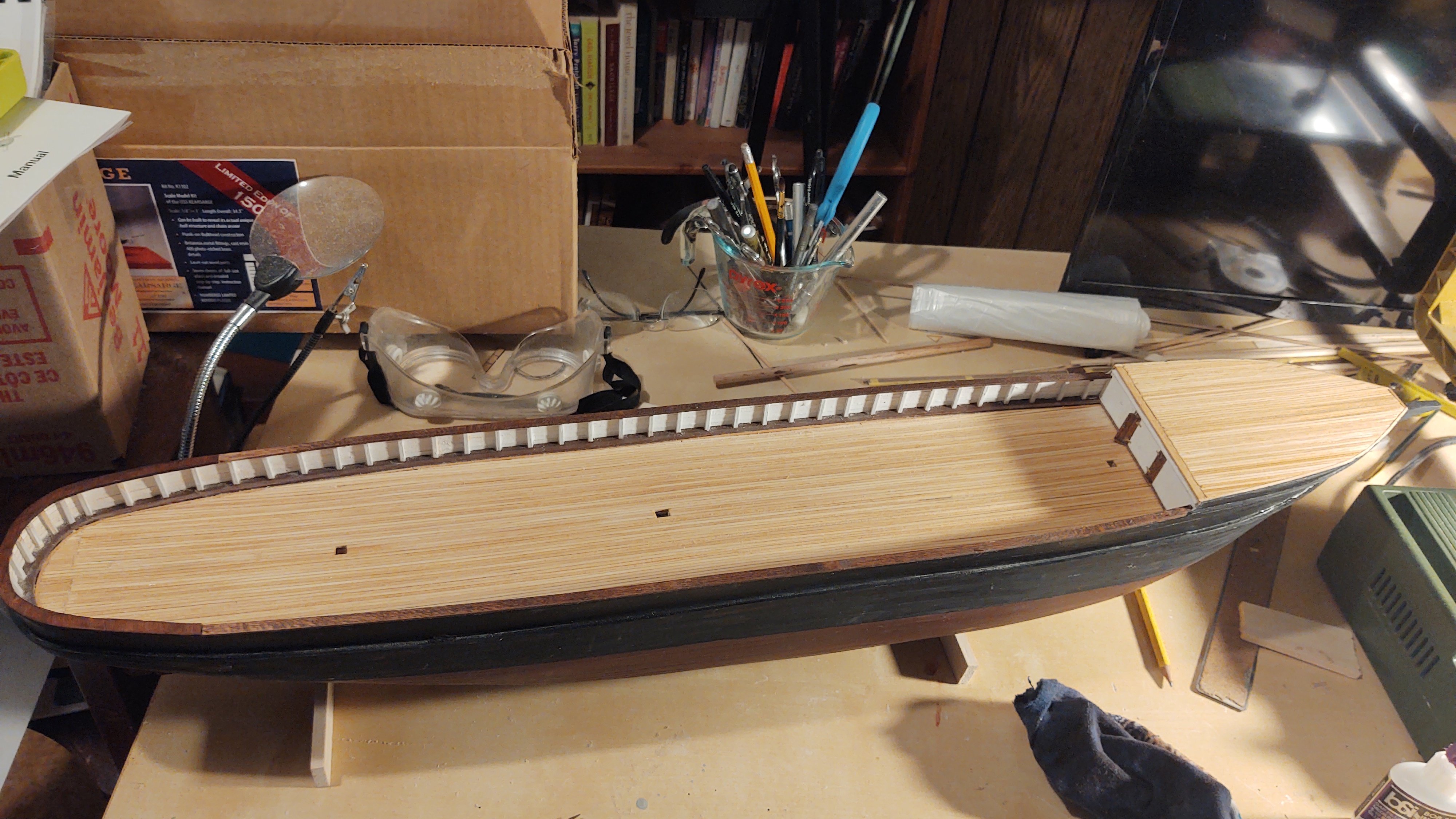
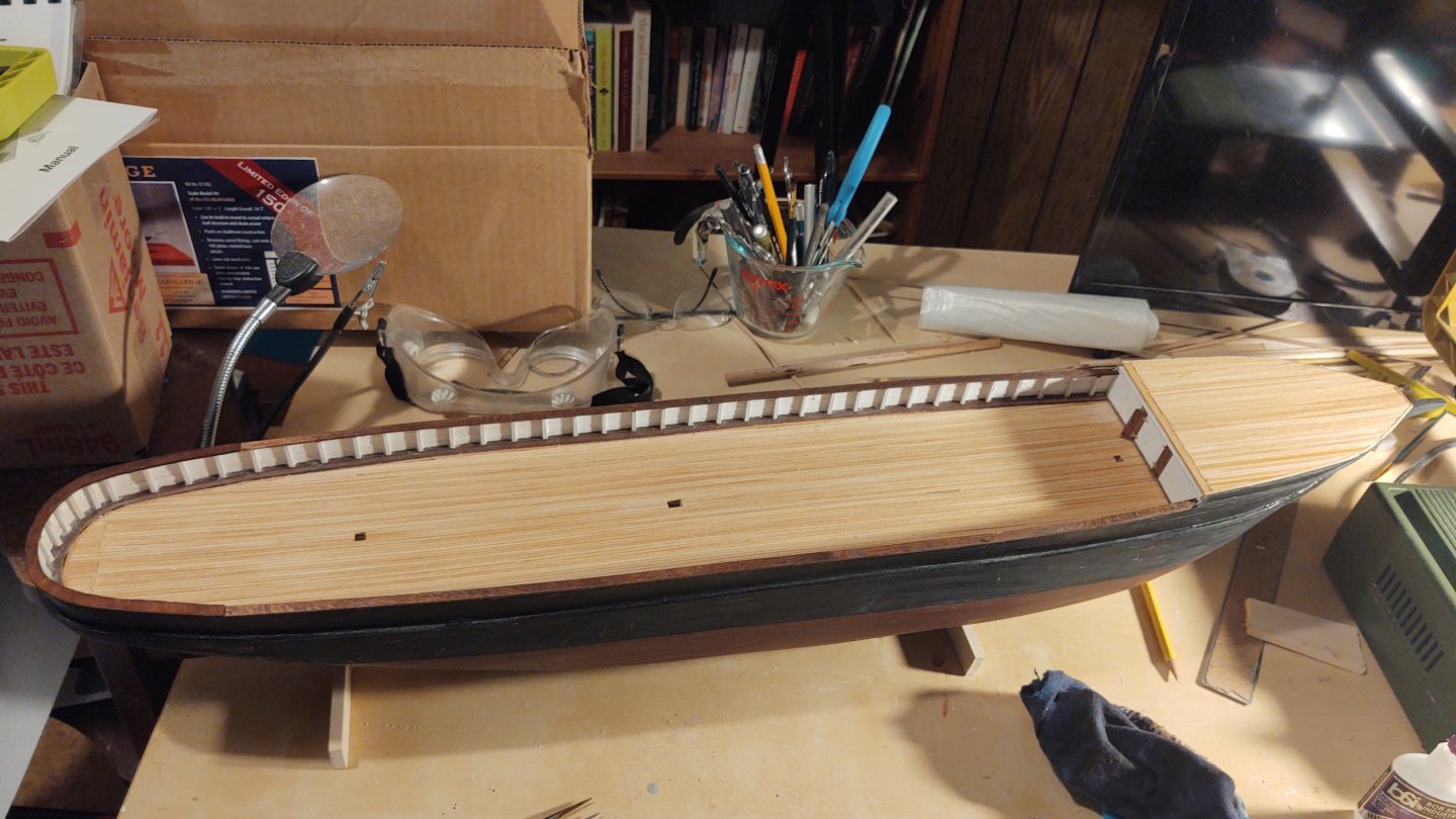
Quick update. I've cut, stained and installed the cap rails. Most of the rail is made from 1/16 thick bass I cut to 6 mm wide. The stern is cut to match the stern from a piece of 1/16 bass sheet and fitted in place before staining and permanently gluing. Regards, George


-
Rick, That makes a lot of sense. The ship was not a great sailer, and if it was pinwheeling a prop with a steam engine attached, I imagine it would be a lot worse. Regards, George