RobZorba
-
Posts
90 -
Joined
-
Last visited
Content Type
Profiles
Forums
Gallery
Events
Everything posted by RobZorba
-
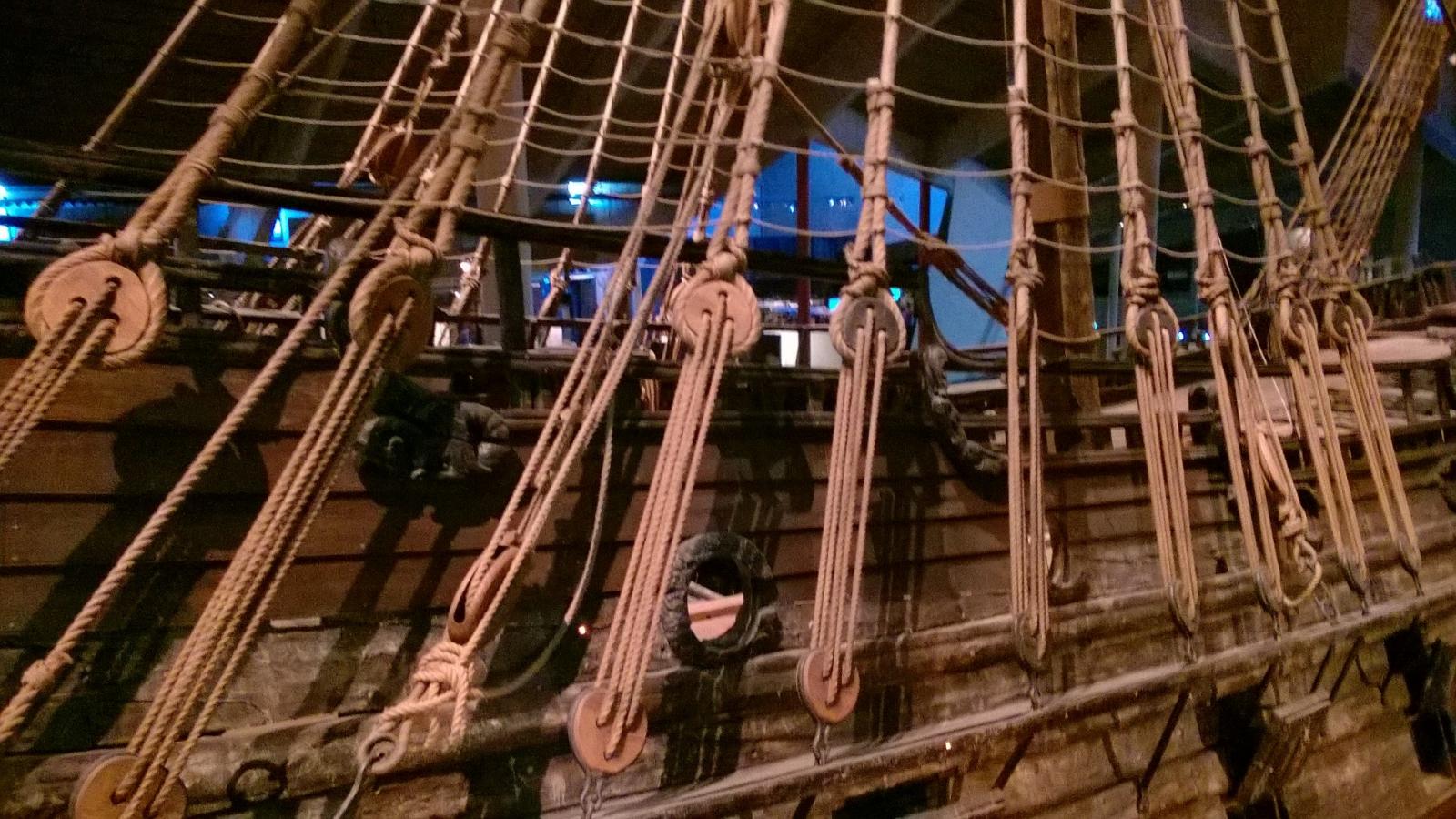
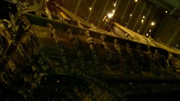
 And finally some other images from the museum that may help with building fixtures and fittings:


- 86 replies
-
- 3
-

-
- billing boats
- wasa
- (and 1 more)
-
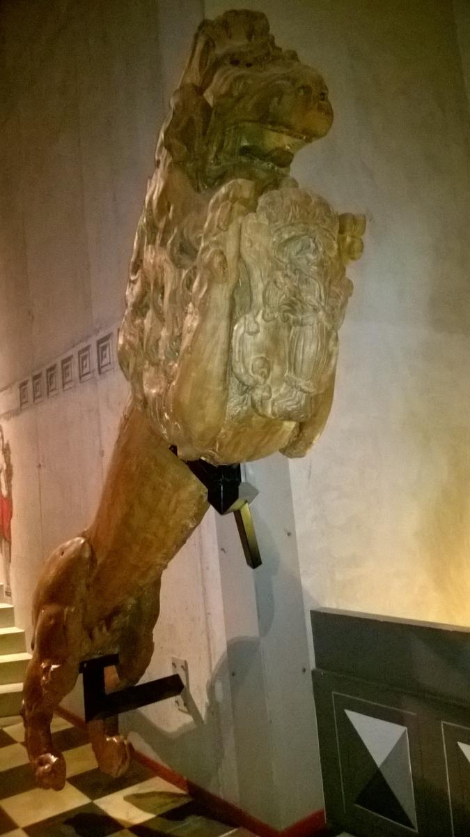
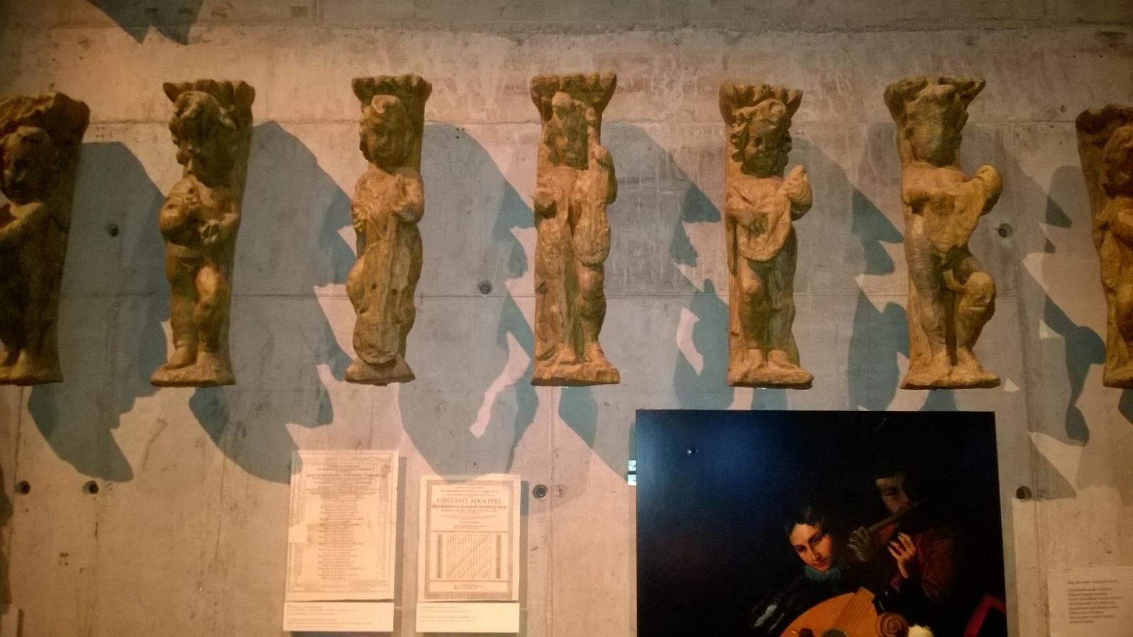
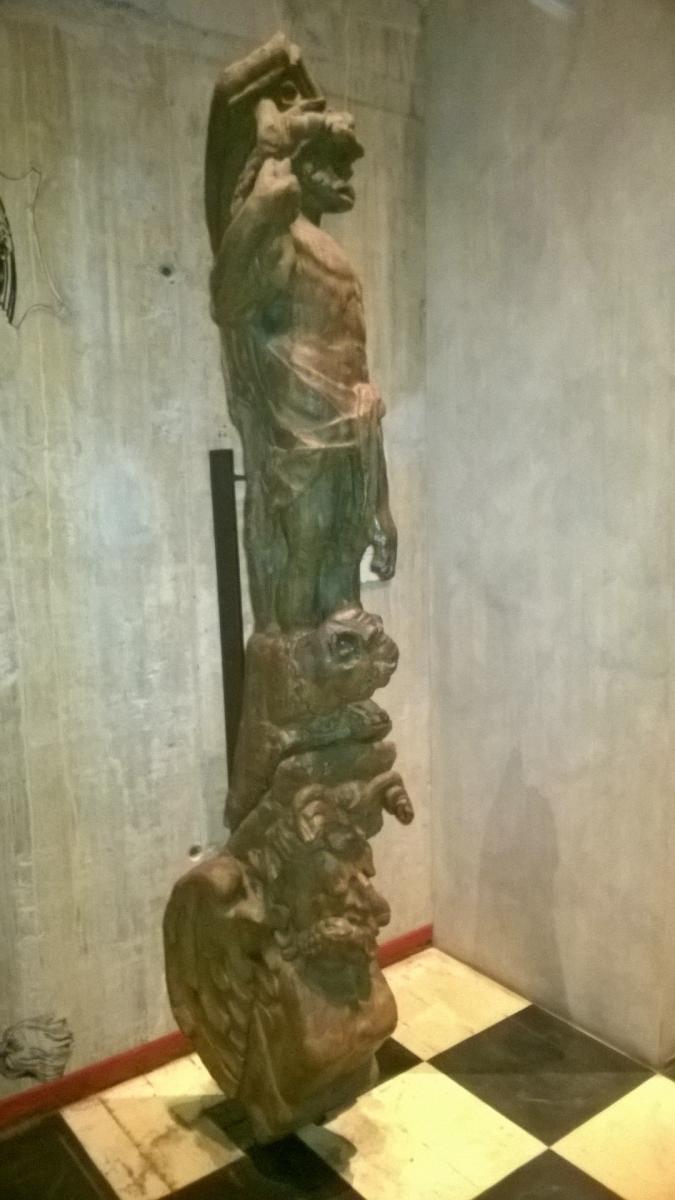
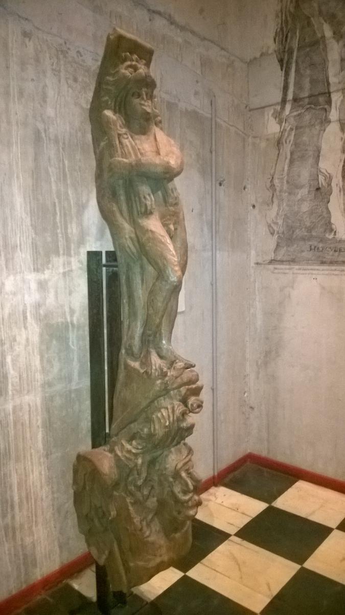
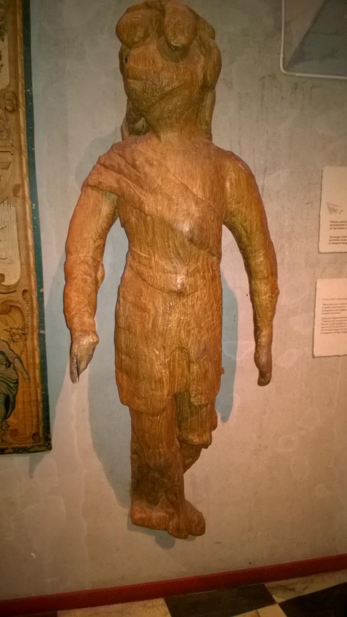
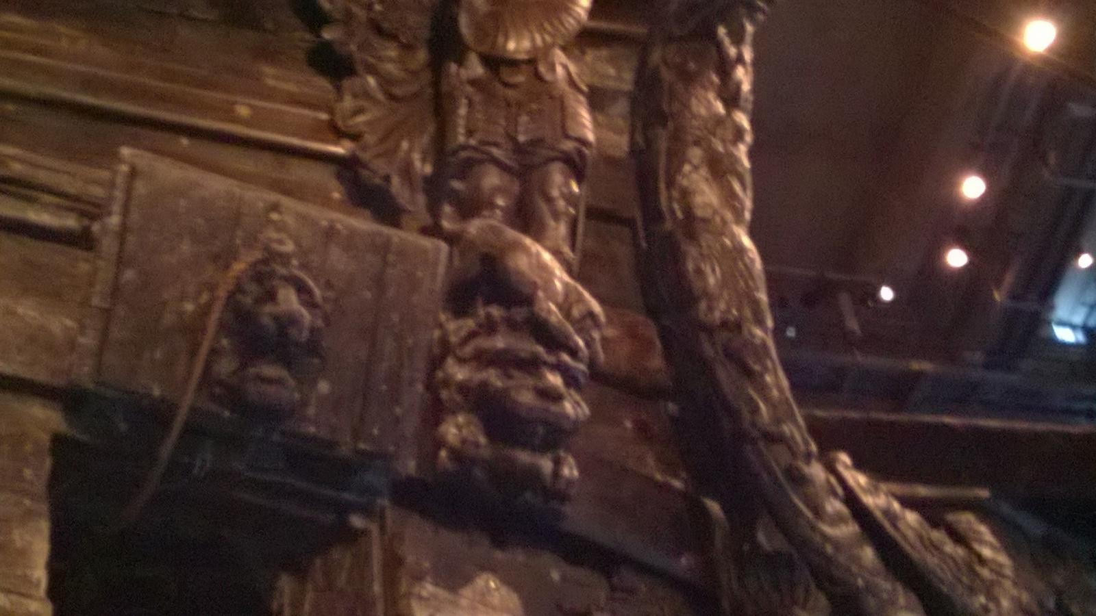
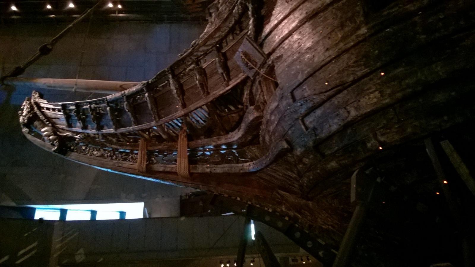
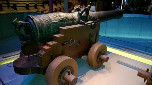
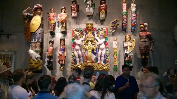
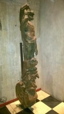
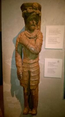
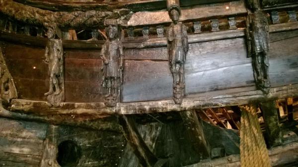
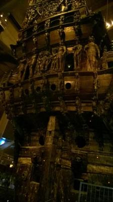
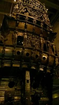
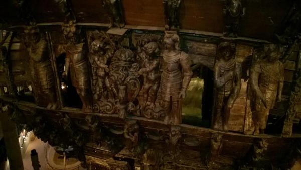
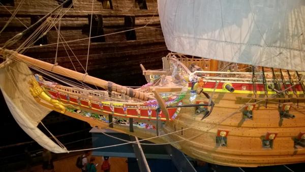
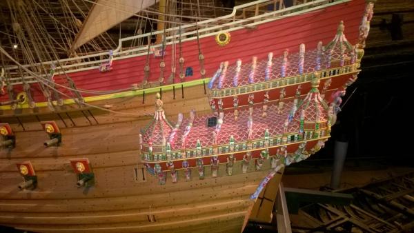
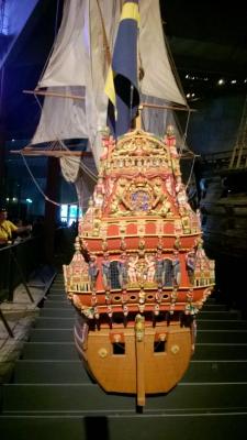
Now a set of images of the "full size" figure carvings on the actual Vasa, plus the Museum's reconstruction of the paint colors that were used on the original:


- 86 replies
-
- 2
-
-
- billing boats
- wasa
- (and 1 more)
-
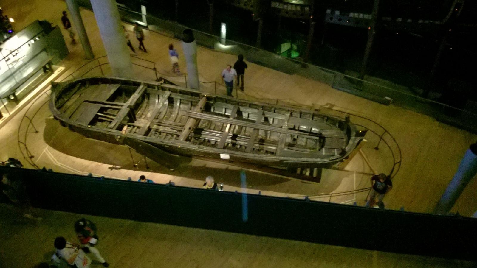
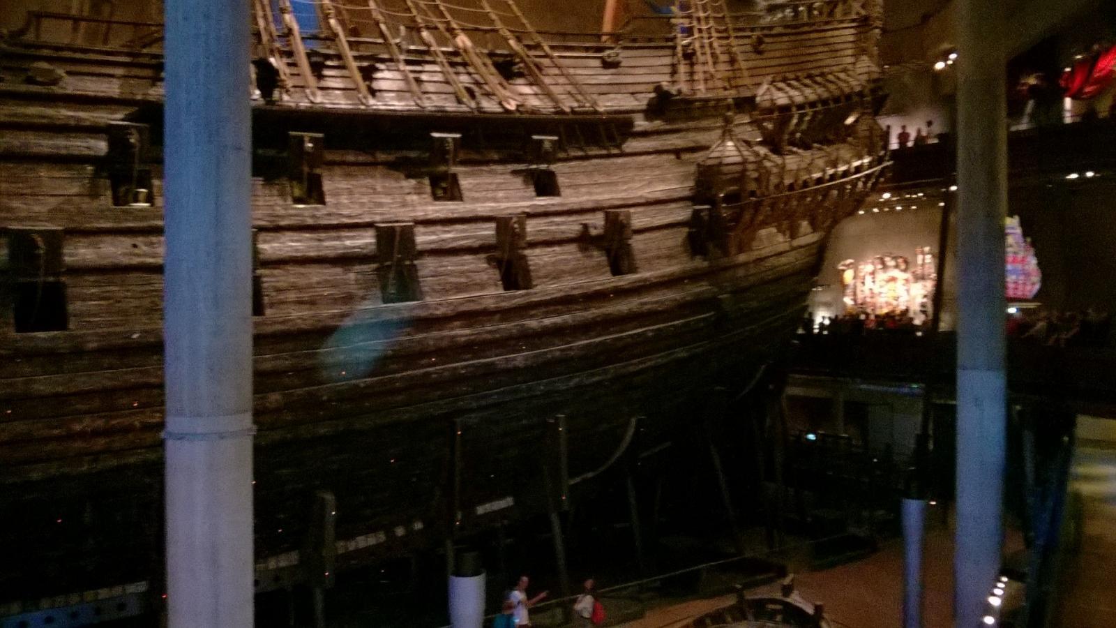
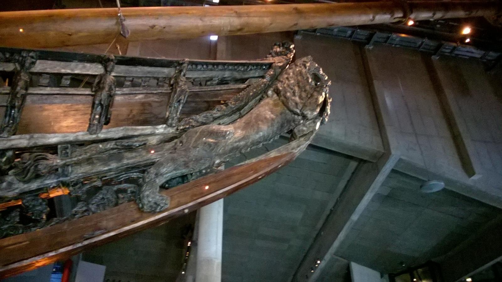
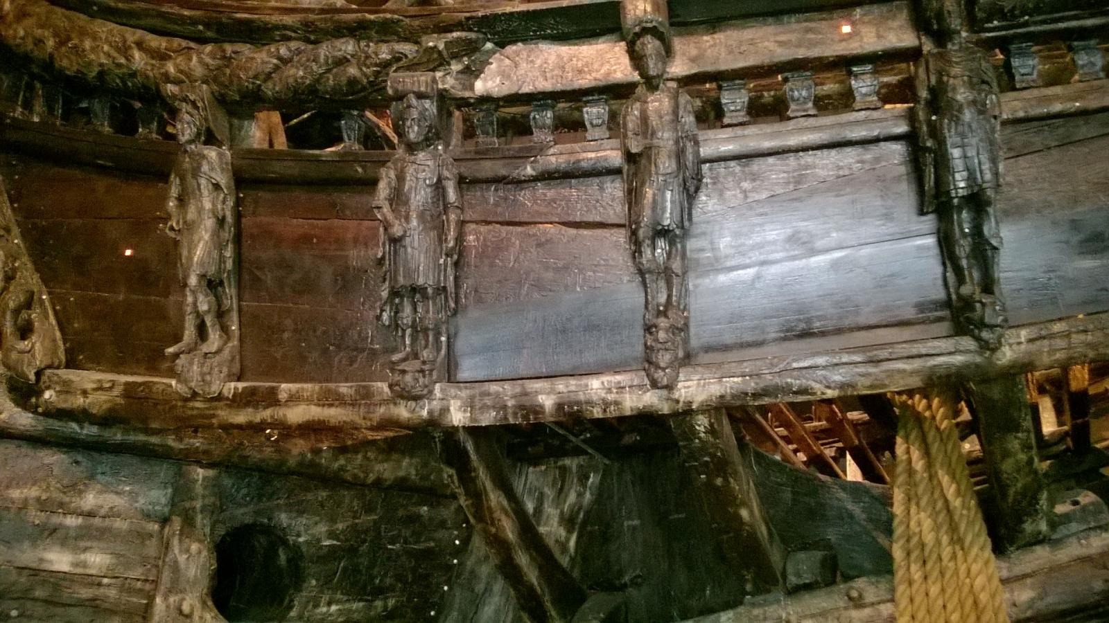
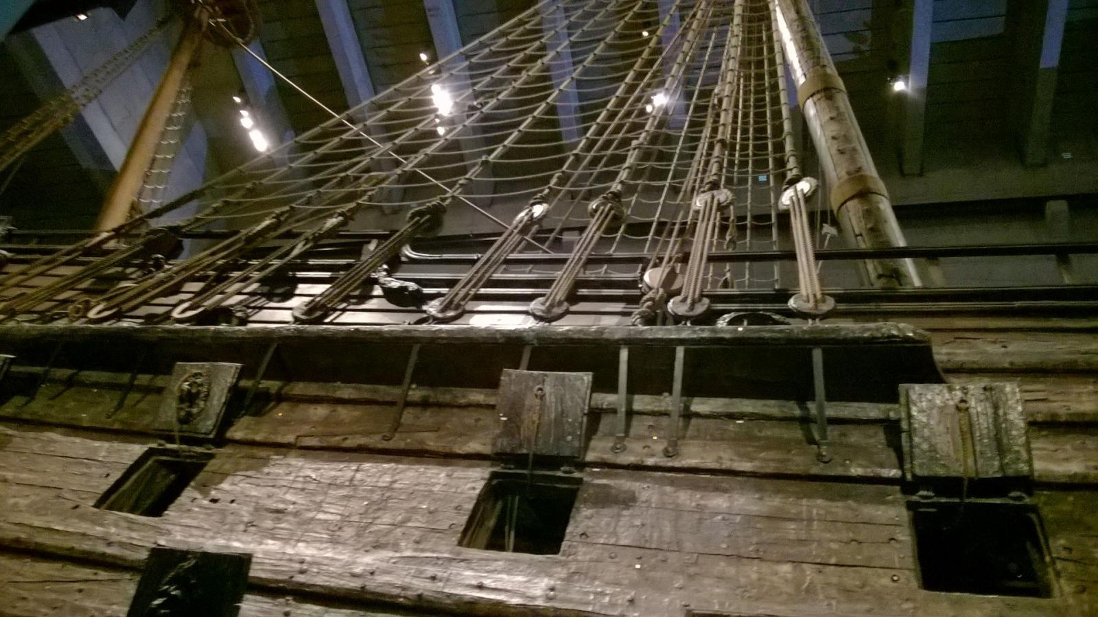
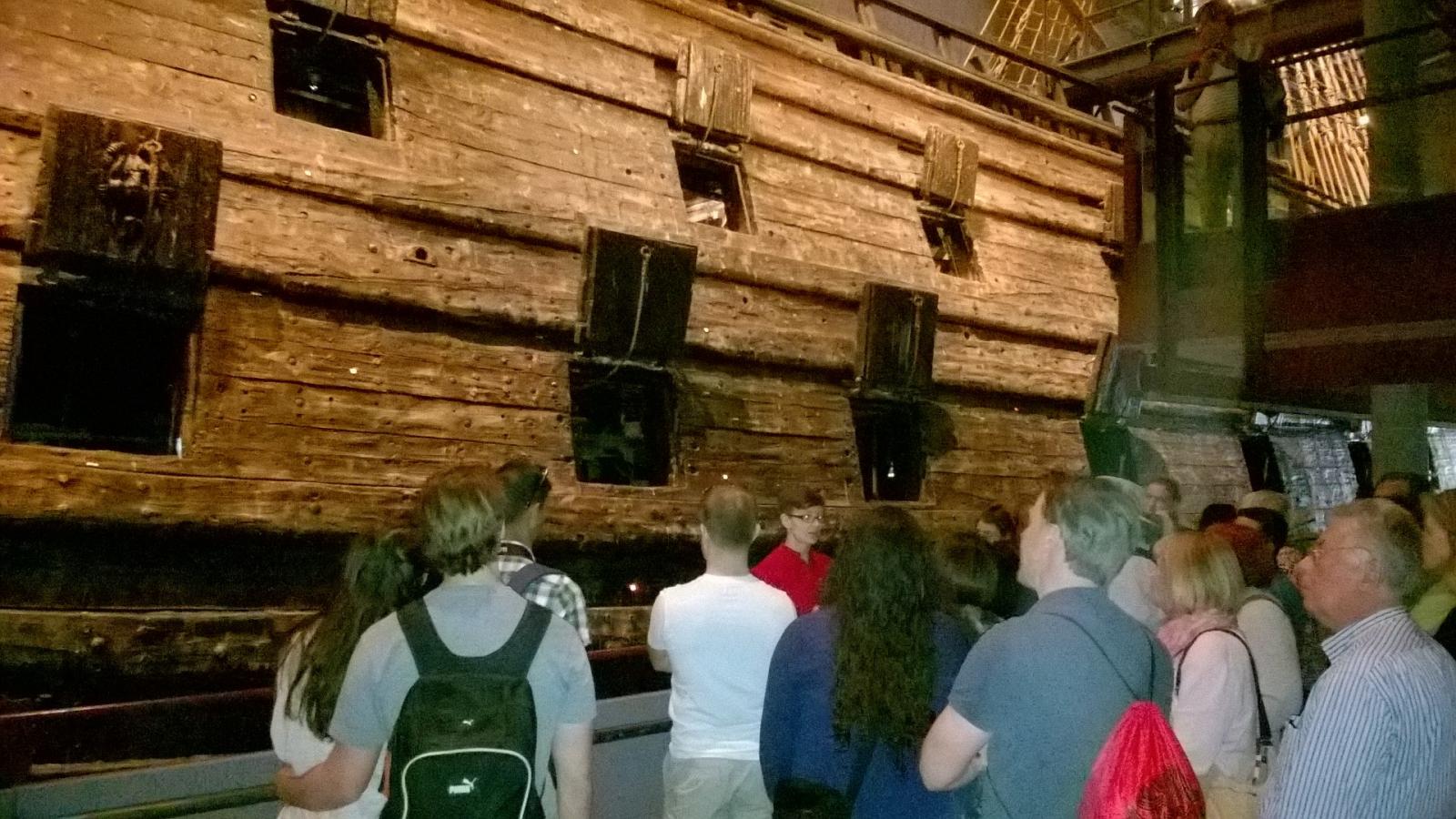
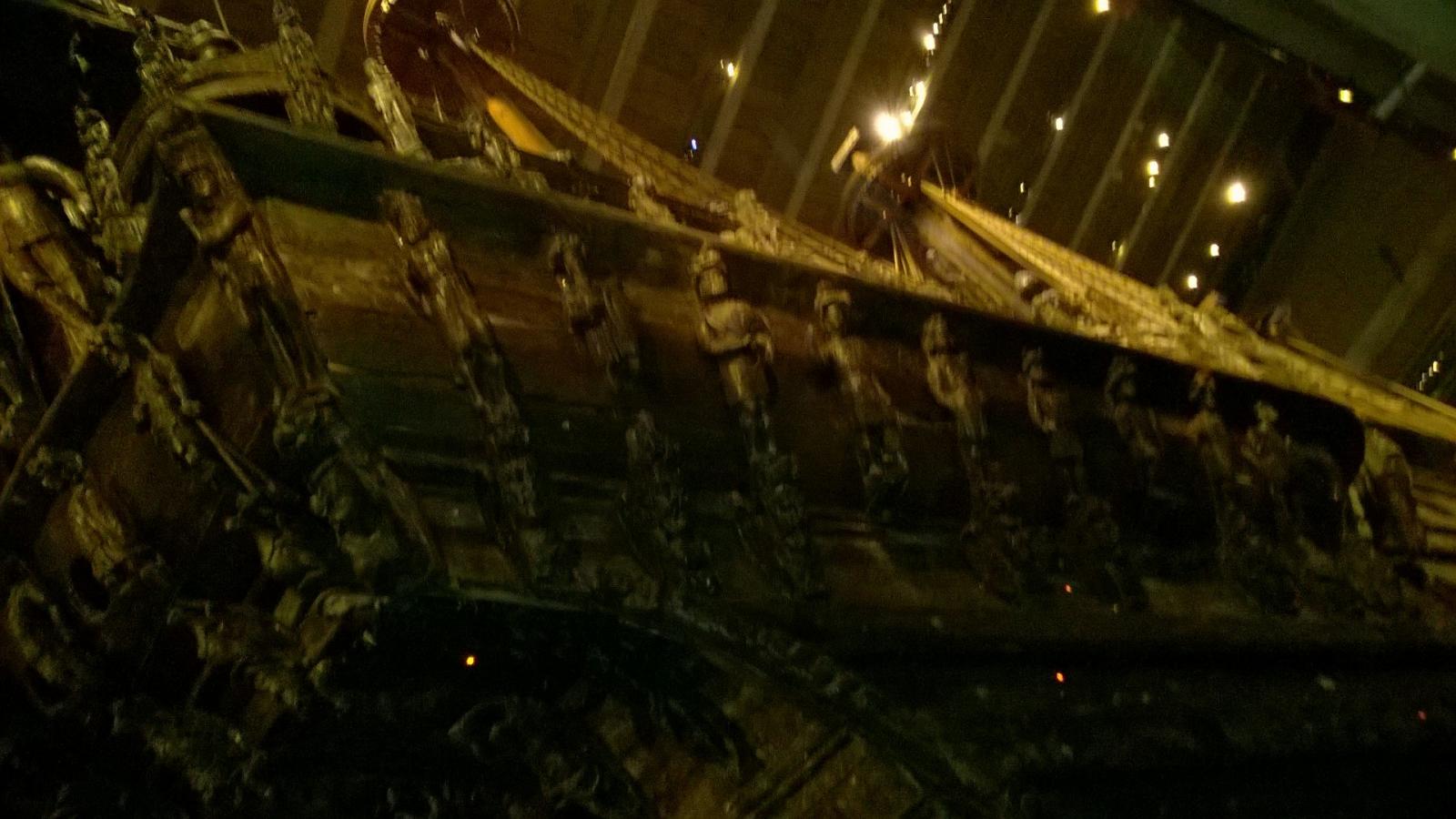
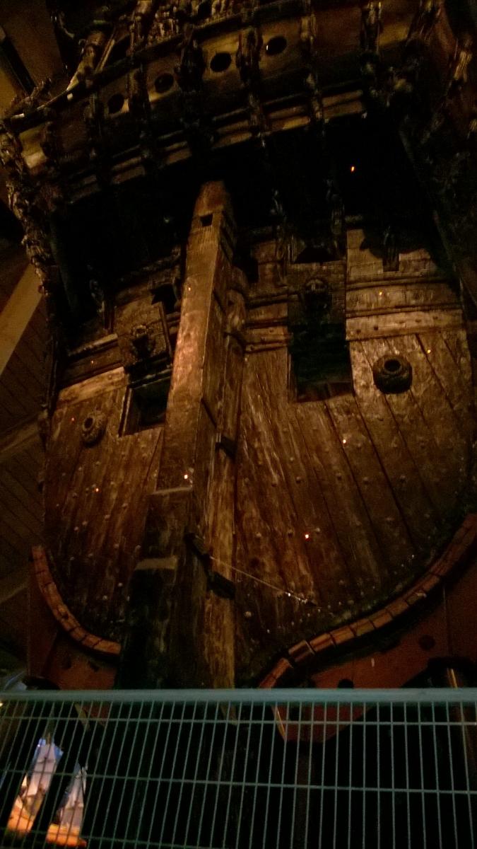
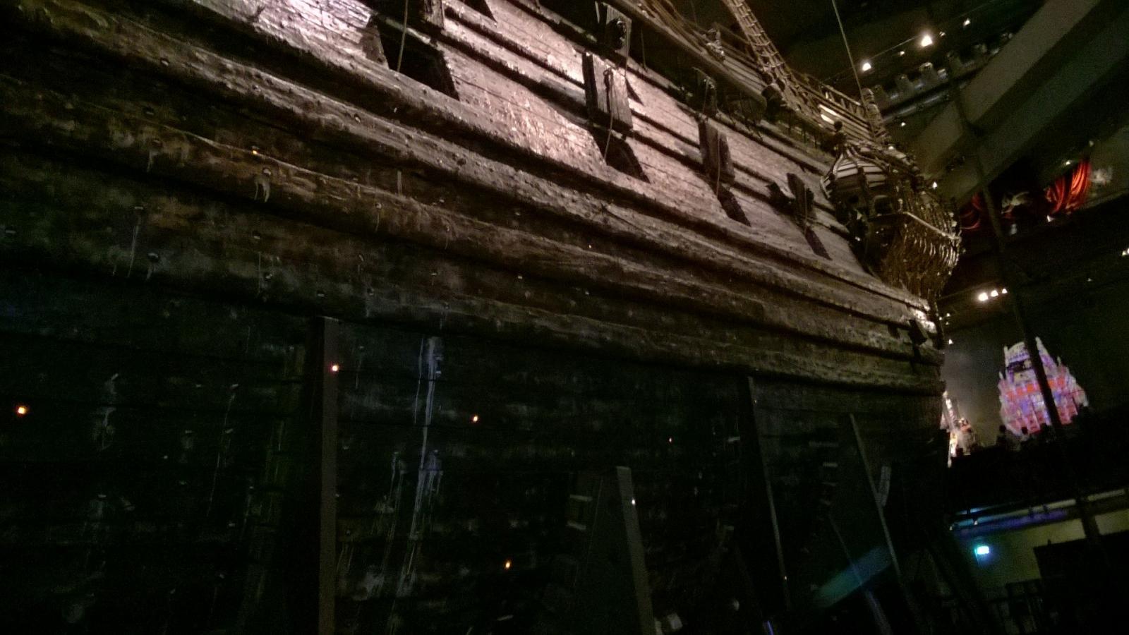
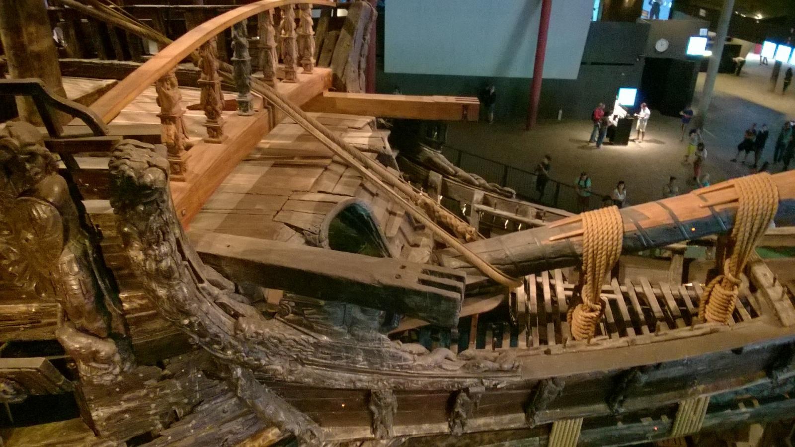
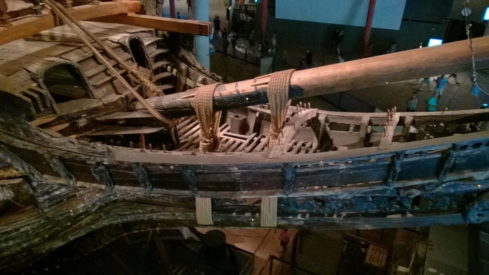
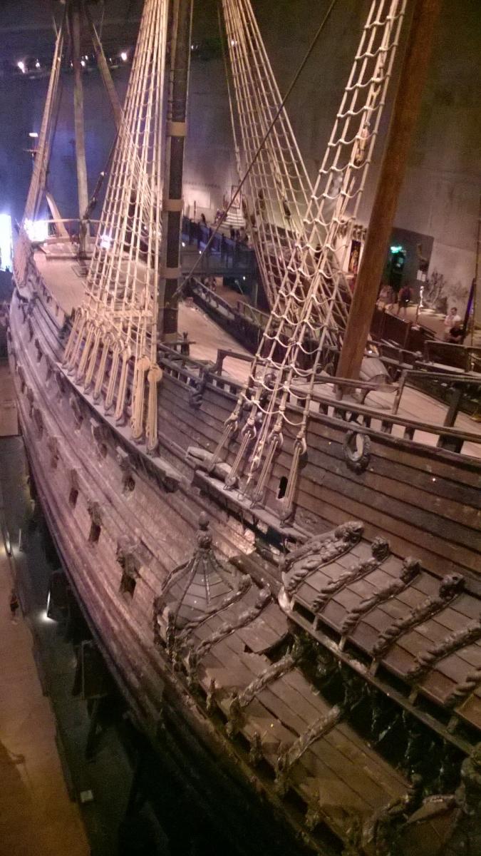
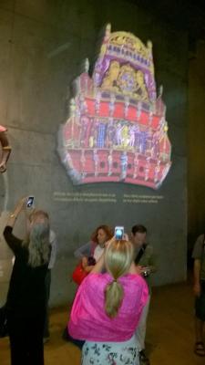
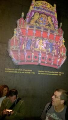
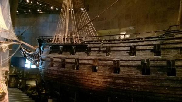
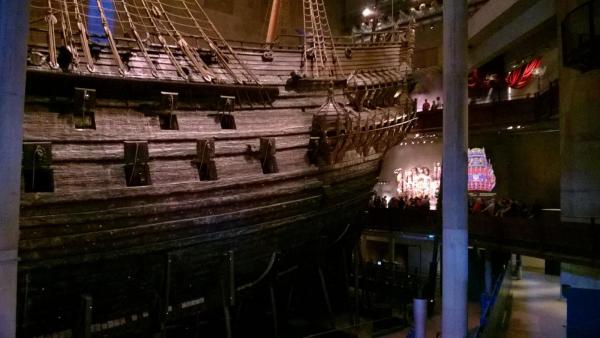
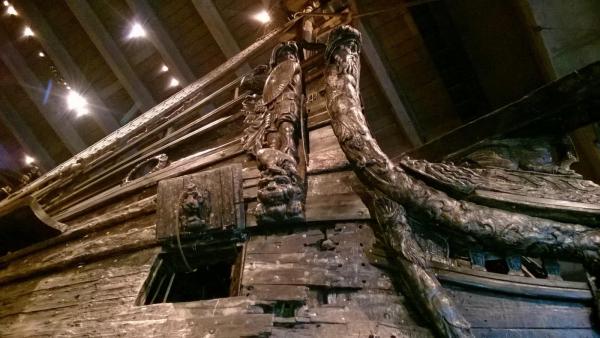
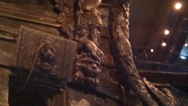
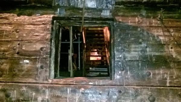
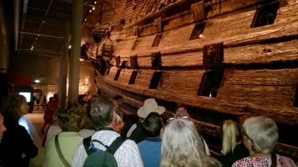
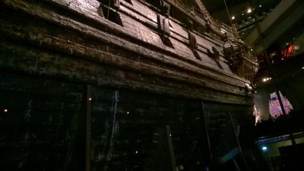
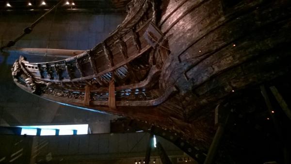
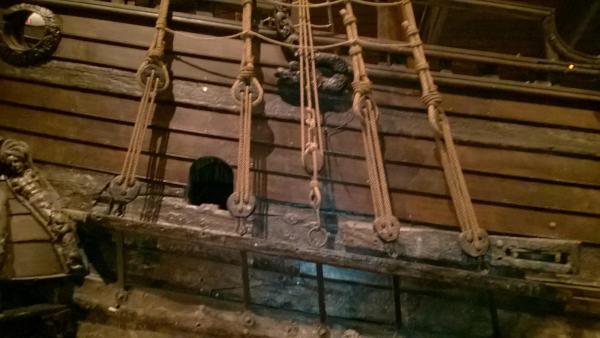
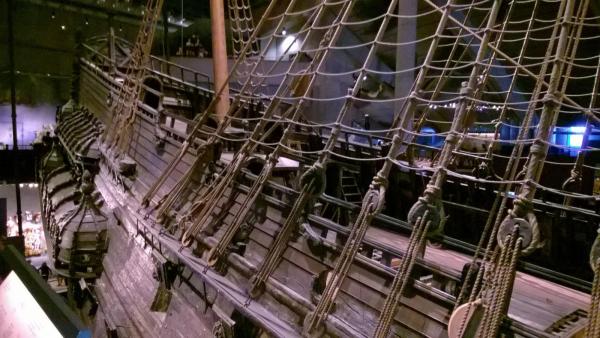
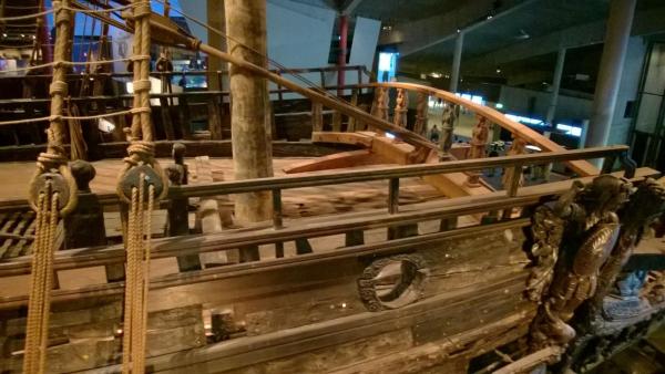
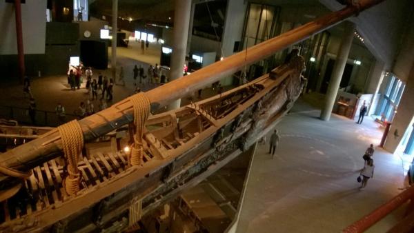
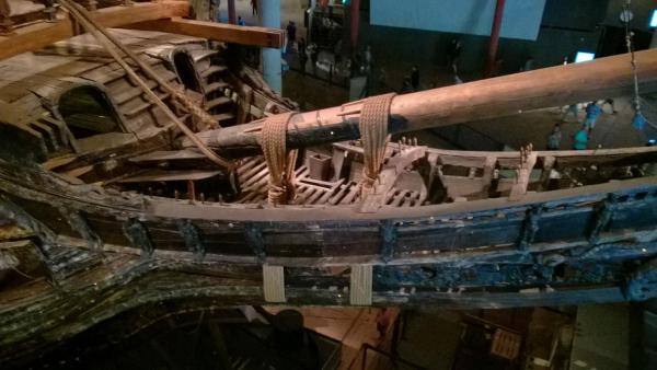
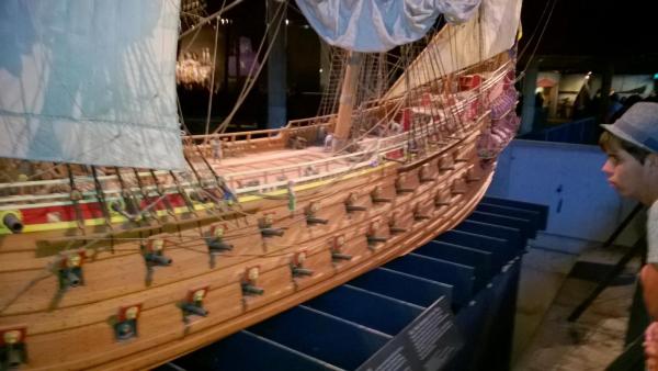
Now a set of images of the actual Vasa which is preserved in the museum:


- 86 replies
-
- 3
-
-
- billing boats
- wasa
- (and 1 more)
-
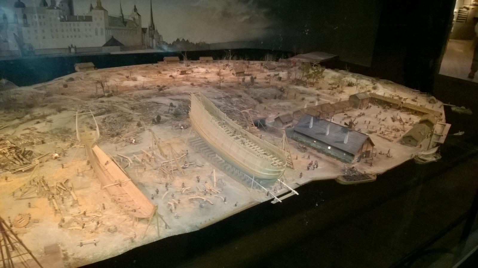
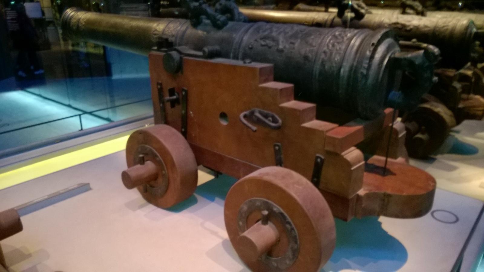
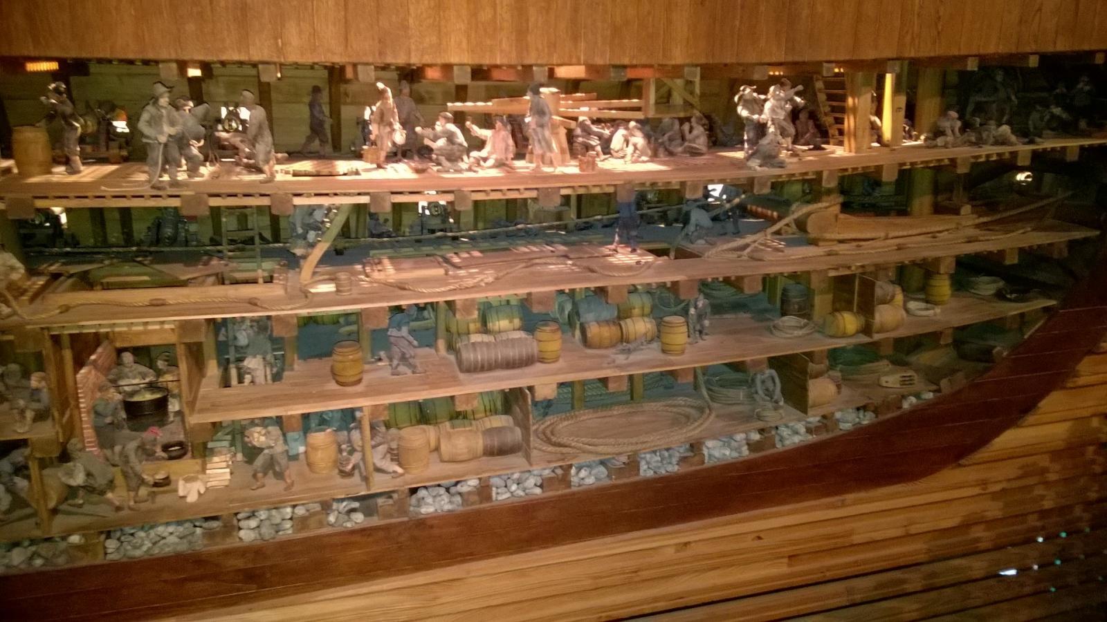
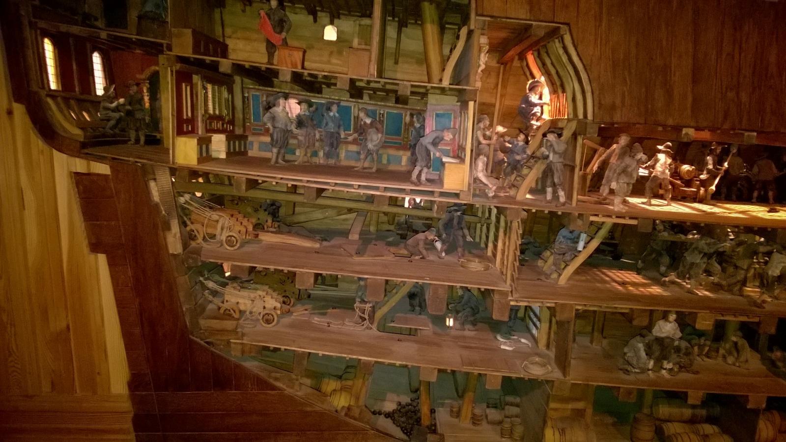
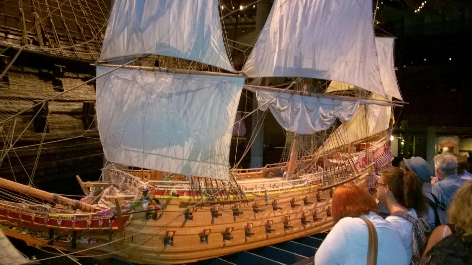
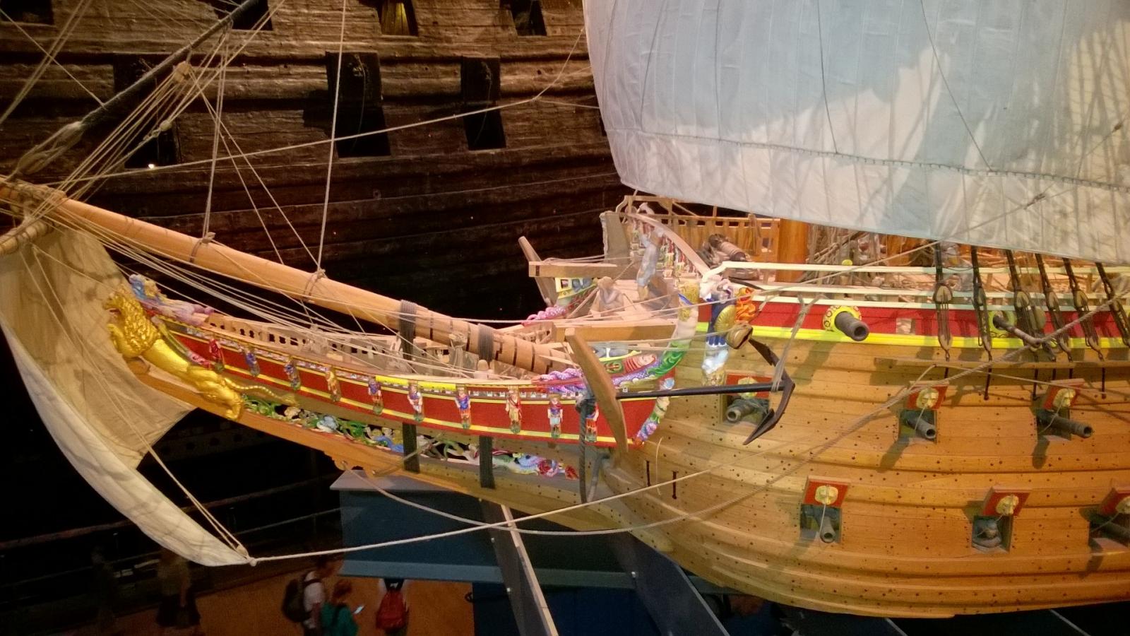
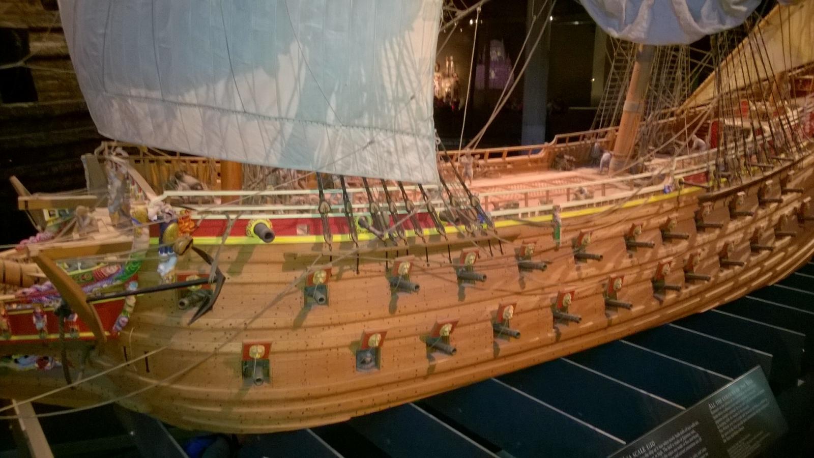
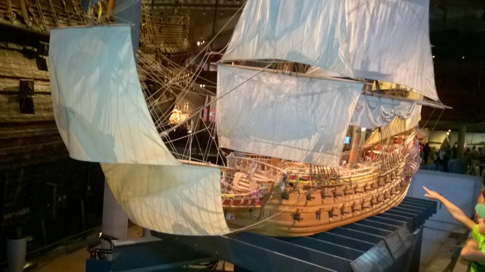
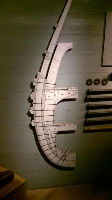
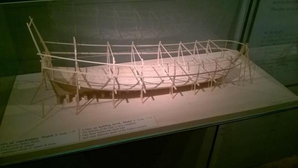
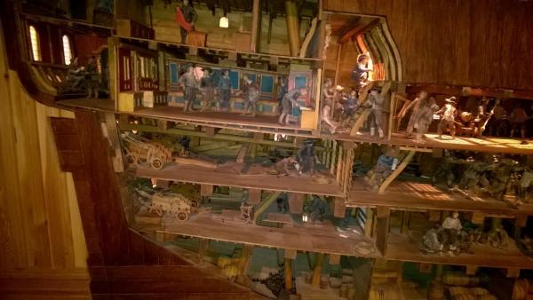
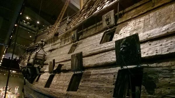
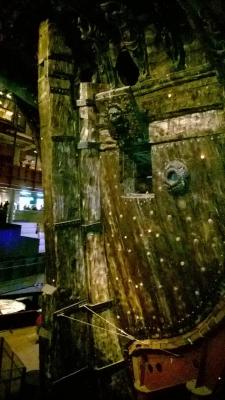
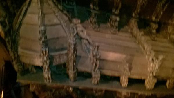
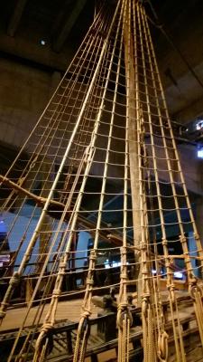
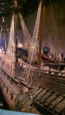
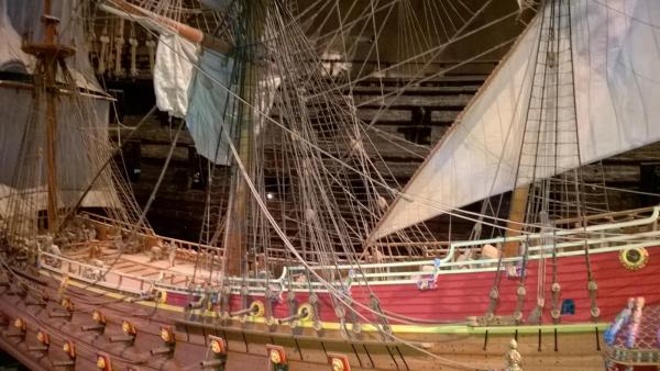
At this point I will post some of the pictures I took in the VasaMuseet, in case any of these pictures help other Vasa model kit builders. The pictures have been invaluable for me. I keep a copy on my smartphone, and I often look at the museum images when trying to decide whereabouts each part in the Billing Boats kit needs to be fixed. This first set of images is of the 1:6 scale museum model which is about twenty feet in length.


- 86 replies
-
- 3
-
-
- billing boats
- wasa
- (and 1 more)
-
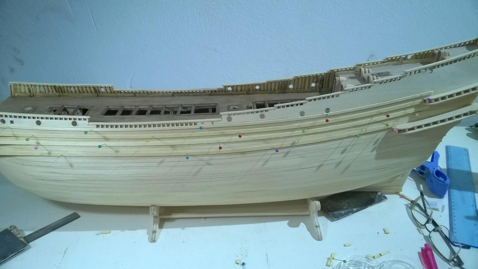
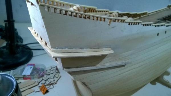
Another picture of the "test fit" of the cladding pieces ... the spacing is correct in this photo ... the 4 mm strip 2 links to the center of the upper gallery. The 3 mm strip 1 hugs the bottom of the lower deck railings, and just touches the bottom of the first and last cannon opening on the open decks. Strips 1, 2, and 3 occupy an overall width of 19.5 mm. The spacing from the bottom of strip 3 to the top of strip 4 is 16 mm, and the area between these strips defines the upper gun deck where I will cut gun port openings later. Like all the other Billing Vasa kit builders on this forum, I do not like the idea of the frames for gun ports being glued on the surface of the hull. On the actual ship, the gun ports are openings in the hull with a wooden frame that sits inside the surface of the hull planking, not on the outside. So I will cut gun port openings also. But I don't want to go to the trouble of building lots of little boxes and buying replacement "longer" canon. My "idea" for how to "sink" the gun port frames into the hull and still be able to use the stub cannon supplied with the Billing kit is as follows. I will glue a small square of 3 mm acrylic (safety "glass") to the rear of each plastic frame. Drill the center of the acrylic to fit the dowel on the rear of the stub cannon. Paint the rear of the acrylic matt black. Paint the window frame red with gold trim. Paint the canon with an unevenly stirred mixture of Humbrol antique bronze and gunmetal paint. Glue the canon in place. Then stick the completed assembly using Cyano into the gun port opening that I cut, using the canon as a "handle" with which to position the frame accurately into position before "kicking" the Cyano with acceleratort. I will cut the openings one at a time, insert and glue one gun assembly and then cut the next one. This will minimise any risk of hull planking moving out of position.

- 86 replies
-
- 4
-
-
- billing boats
- wasa
- (and 1 more)
-
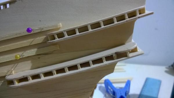
Here's the stern gallery (in progress) with the excess length of the timbers trimmed off using a fine toothed Dreme cutting saw. In the photo, I am also "test fitting" some of the hull cladding pieces to get the spacing correct. In this photo the overall width taken by these three strips was 25 mm and was not correct. I had to move the first and third cladding strips closer together so the overall width taken by these three strips was 19.5 mm.
- 86 replies
-
- 1
-
-
- billing boats
- wasa
- (and 1 more)
-
Thanks Piet, it seems you have a "Dutch" first name ... of course, you know the Vasa sank on its maiden voyage. The Dutch shipbuilders were working to a "specification" issued by the King of Sweden which included standardised (heavy) guns on all decks and a narrow and shallow design presumed to "go faster" through the water. Previous ships had lighter cannon on the two upper decks. So, it was top heavy and rolled over and sank when one of the crew sneezed. During the ensuing inquiry, the Dutch workmanship was not faulted, nor was the Admiralty held responsible.
- 86 replies
-
- 2
-
-
- billing boats
- wasa
- (and 1 more)
-
Thank you Brian. What I learned when building the Bounty was that I did not have a clue to plank hulls or decks at the time. I made a mess of it, it sat dormant for 6 years gathering dust, and eventually I threw ithe model away in disgust, just keeping the brass fittings and some spare wood. But this time I've read many books and articles and have made an acceptable attempt (for me), but not yet a good enough attempt to be fully satisfied. I did everything by "calculation" of the width of plank needed at each frame to keep the number of planks constant on each frame. But this method did not prepare me for the sideways twisting of planks that occurred. Also, I should not have tapered any plank to less than half its original width. I should have used more "stoppers" and "fillers". Next time I plank a hull, I will not permit any sideways twisting of a plank, I will leave it fall on each frame exactly where it wishes, and use more stoppers and fillers where necessary.
- 86 replies
-
- 3
-
-
- billing boats
- wasa
- (and 1 more)
-
Thanks Elijah. I use PVA fast drying wood glue for parts that require a large glue area all at once, such as the decks and deck planking - it sets in about 90 minutes. It is waterproof when dry but is water soluble while liquid so you can clean up with a damp cloth. Then I use "Bullfix" which is a slow setting Cyano together with an aerosol accelerator that sets it in 2 seconds. I have to be very careful not to use excess Cyano because if it "spreads" onto a surface I want to stain or paint, it prevents the stain or paint from sticking. There are occasional "accidents" and after the Cyano has set, I use a Dremel "router tip" bit to carefully clean it up and get back to the clean wood. For the hull planking I left a small 0.3 mm gap between planks, I did not glue them together initially, and I used a small drop of Cyano on every frame. Occasionally the Cyano "spread" into the gap between planks, and in those cases I used a Dremel cutting disk to remove the Cyano. After planking the hull I sanded it down to remove the uneven edges from one plank to the next. Then I used a water-based ebony color wood putty to fill all the gaps and simulate caulking. I pressed the putty well into the gaps so it flowed through to the inside of the hull. Then I used a slightly damp rag to wipe off the excess putty, being careful not to get the hull too wet. By wiping carefully there was no puttly left on the surface of the planks. Then I sanded the hull very lightly with very fine emery.
- 86 replies
-
- 3
-
-
- billing boats
- wasa
- (and 1 more)
-
I'm building the Billing Boats Vasa currently, and as you know the written instructions are sparse. Can anyone help me identify which color (white / black / grey-brown) the various aspects of rigging should be? a) For example in 1636 did the Swedish shipbuilders use tar-stained black shrouds? Were any of the ropes actually white as per many of the spools supplied by Billing Boats? ... seems improbable to me, I thought hemp was used and it's kinda yellow-brown in color, not white. At the moment I am thinking of bleaching all the threads supplied in the Billings kit, and then mixing some fabric dye to get a dark yellow-brown color, then dyeing all the threads the same color. But maybe some of the rigging was color coded in some way? Maybe they tarred some of the rigging e.g. shrouds. I just don't know, so would value some advice ... Many thanks, Rob
-
At this point I have not yet cut holes for the gun port openings in the side of the hull. It's something I will do later once the rest of the hull timber strips have been fixed in place. I will use these as the guides for where the gun port openings will be cut. I have a cunning but simple plan for how to modify the Billing gun ports to achieve a more realistic appearance, but I don't want to go to the trouble of making false boxes for every gun port. I'll post pictures of the gun port modifications later on in this build log.
- 86 replies
-
- 2
-
-
- billing boats
- wasa
- (and 1 more)
-
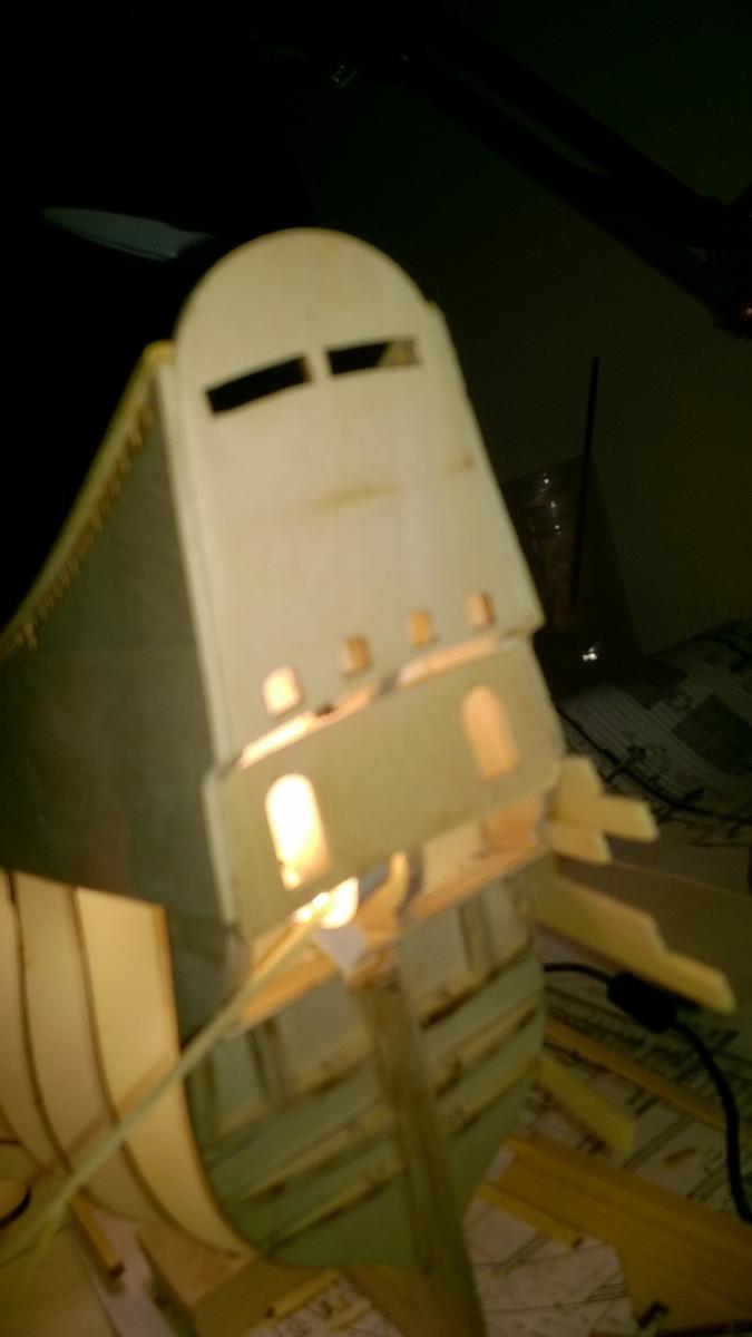
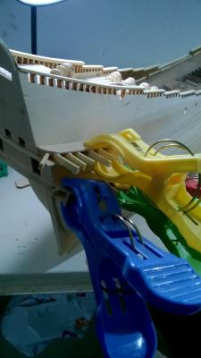
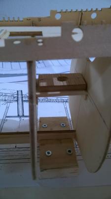
Because I had used 4 mm wide timber strips, the height of each piece was exact and followed the curvature of the lower stern gallery plate perfectly. I then used PVA glue and spring clamps to fix the upper stern gallery plates in place. The assembly was very robust and much stronger and more accurate than would be the case if I had used 1 mm x 1.5 mm window brace pieces. You might notice a couple of pieces glued at a 45 degree angle. This is because the conical pieces that will be fitted later have decorative mouldings fitted every 45 degrees and the mouldings also fix to the vertical window post.
- 86 replies
-
- 3
-
-
- billing boats
- wasa
- (and 1 more)
-
After the lower stern gallery plates were glued in place, I measured the exact spacing for the window bracing pieces from the Billings side elevation, and marked the brace piece positions on each lower plate. These braces have to fit flush with the upper stern galery plates because the platic mounlding / ornamentation pieces will be glued to these later. I used strips of 1 mm x 4 mm timber to make the window posts instead of the tiny 1 mm x 1.5 mm strip stated on the Billing plans. At only 4 mm in length these tiny 1 mm x 1.5 mm pieces are too fiddly for me to place accurately. I used Cyano to place the tip of each 1 mm x 4 mm strip in the correct location ... I did not glue the whole length, only the tips by about 1mm.. This is what it looked like after my window brace pieces were glued ...
- 86 replies
-
- 3
-
-
- billing boats
- wasa
- (and 1 more)
-
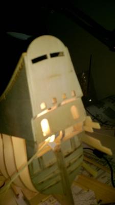
Started work on the stern galleries yesterday. I used a photocopy of the side elevation of the ship, cut it out and used it as a template to mark the exact position of the support pieces for the plywood plates for the galleries. I glued the support pieces in place, then sanded the plywood plates to an exact fit allowing for the curvature of the support pieces.
- 86 replies
-
- 3
-
-
- billing boats
- wasa
- (and 1 more)
-
@Elijah@ Thank you for nice comment. I started the build on 16th September, doing 3 hours per day on average. It's now 29th October so I've put in about 130 hours to date. Have you a model ship project in progress, or are you thinking of starting one?
- 86 replies
-
- 3
-
-
- billing boats
- wasa
- (and 1 more)
-
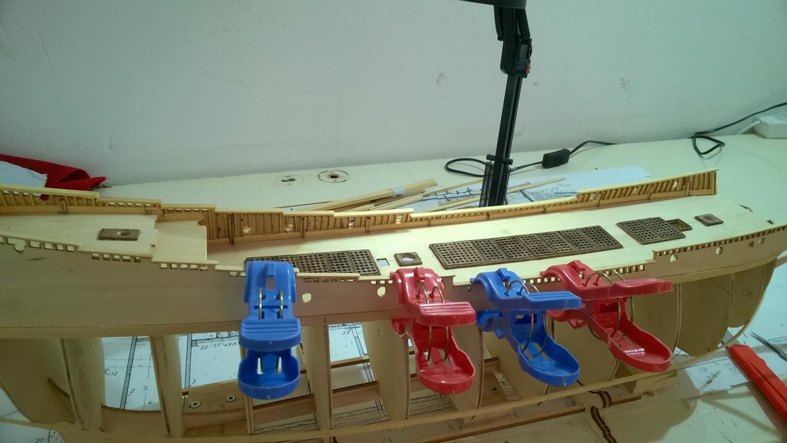
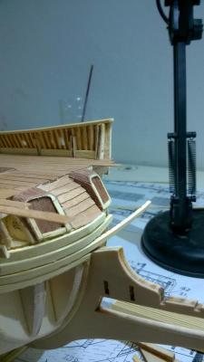
Because the lighting looked so good, I decided not to glue the deck hatches in place, but allow them to be removable. This created a problem because the Billing Boat's kit has no lower gun deck. So restrospectively I made an "imitation" lower gun deck out of some veneered plywood pieces. Better late than never I guess. I did this before planking the hull, sorry my pictures and build log got out of sequence slightly. I will in future make another Billing Boats "Vasa" and the next time, I will modify the frames that are visible from the deck hatches, by cutting rectanguilar slots to follow the line of the upper gun deck and then fitting a single ply gun deck sheet, planking it properly and so on. I also found plans showing the fittings on the upper gun deck, so I would scratch build those parts in future. You live and learn! It woulod be great if Billing Boats made this modification as a standard feature of the kit, it would enhance the quality of the finished model a lot! When displayed, a couple of hatch grating covers would be "part open" instead of closed, and the gun deck visible below.


- 86 replies
-
- 3
-
-
- billing boats
- wasa
- (and 1 more)
-
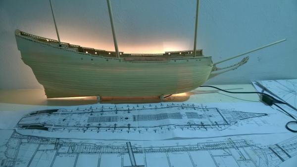
I decided to add lights. I didn't want to fiddle around too much so I bought a 1 meter strip of 3M LED "yellow" lighting complete with 12v power supply. I managed to glue it upside down below the deck gratings so the LED's shine indirectly with reflected light coming up through the gratings. I also cut holes in the rear frames and threaded one end of the strip so it would light up the captain's cabin. In the pictures, the LED strip is not yet in its final centralized position.

- 86 replies
-
- 5
-
-
- billing boats
- wasa
- (and 1 more)
-
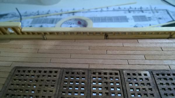
This is the finished planking, sealed with putty and sanded, but not yet stained.
- 86 replies
-
- 3
-
-
- billing boats
- wasa
- (and 1 more)
-
The evil day arrived where I needed to start planking the hull. I read several books about it, I worked out the plank width needed for every frame, I sanded the planks to the right width. But I did hit problems because there are places where the required sideways curvature of the plank is just not gonna work, no matter how much the plank is soaked, steamed, ironed or whatever. So I ended up using "stealers" and so on. The job was not perfect and I think I'd do it differently next time. I glued each plank two frames at a time using a drop of Cyano on the frame, and a cyano "spray accelerator". It was very quick, and meant I did not have the bother of nails and nail holes in the wrong place. I deliberately left a small gap between each plank that would be filled with "ebony" water soluble wood putty later on. This would simulate the tar "caulking" that is used between each plank on the actual Vasa in the museum.

- 86 replies
-
- 3
-
-
- billing boats
- wasa
- (and 1 more)
-
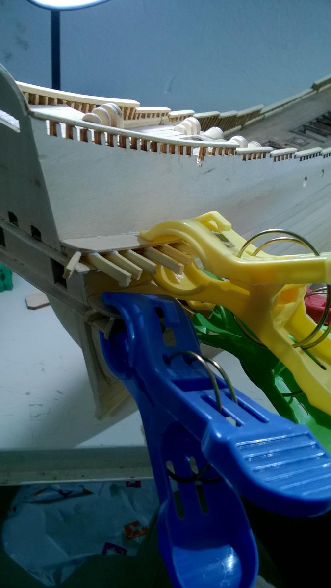
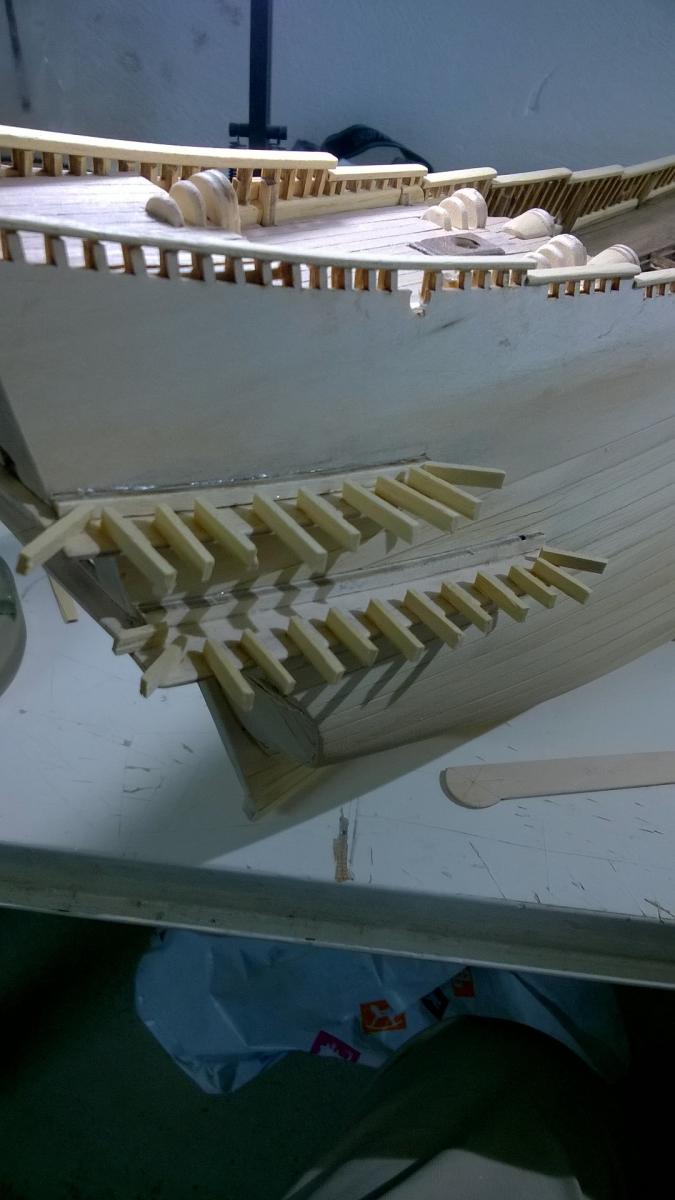
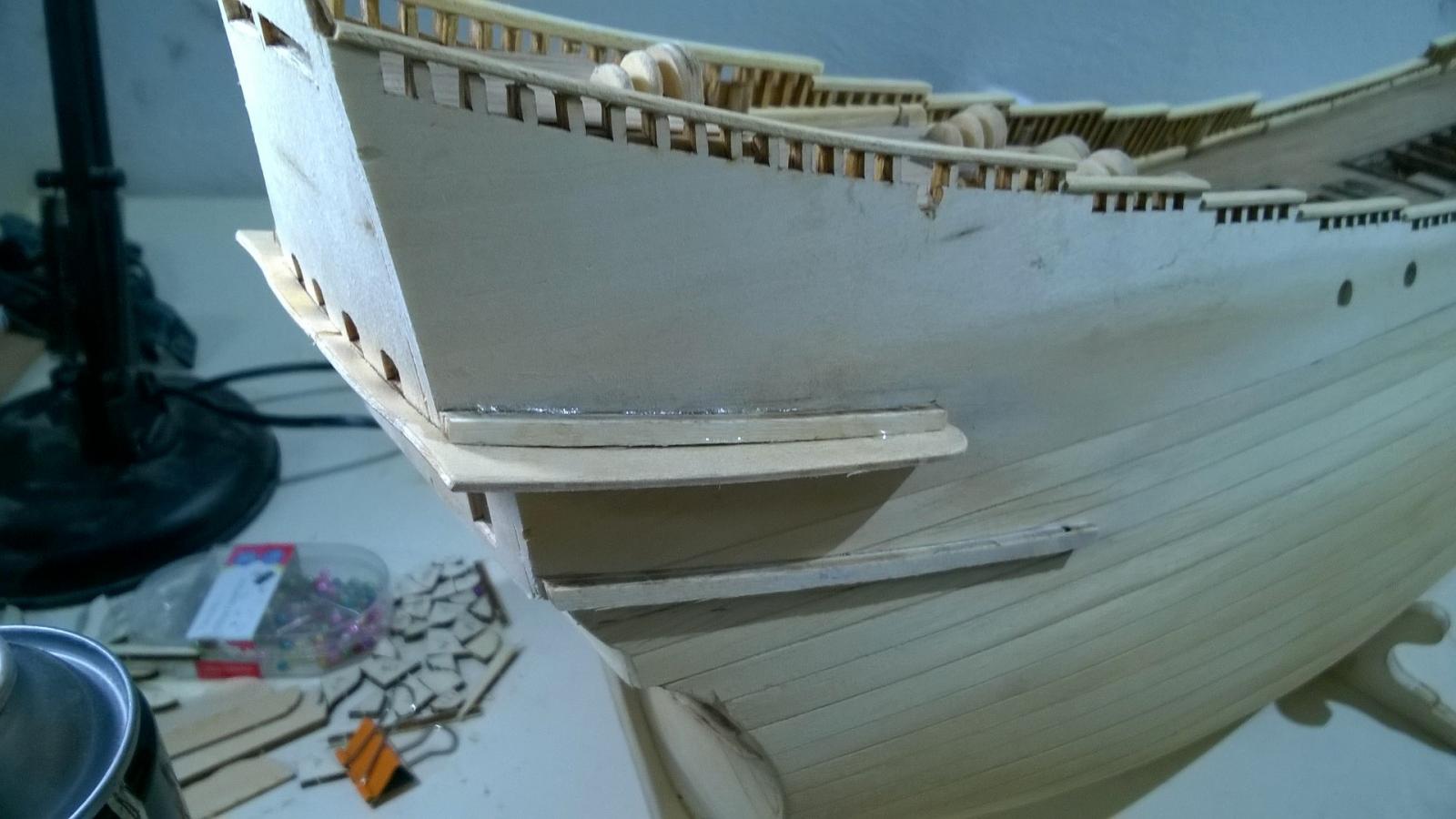
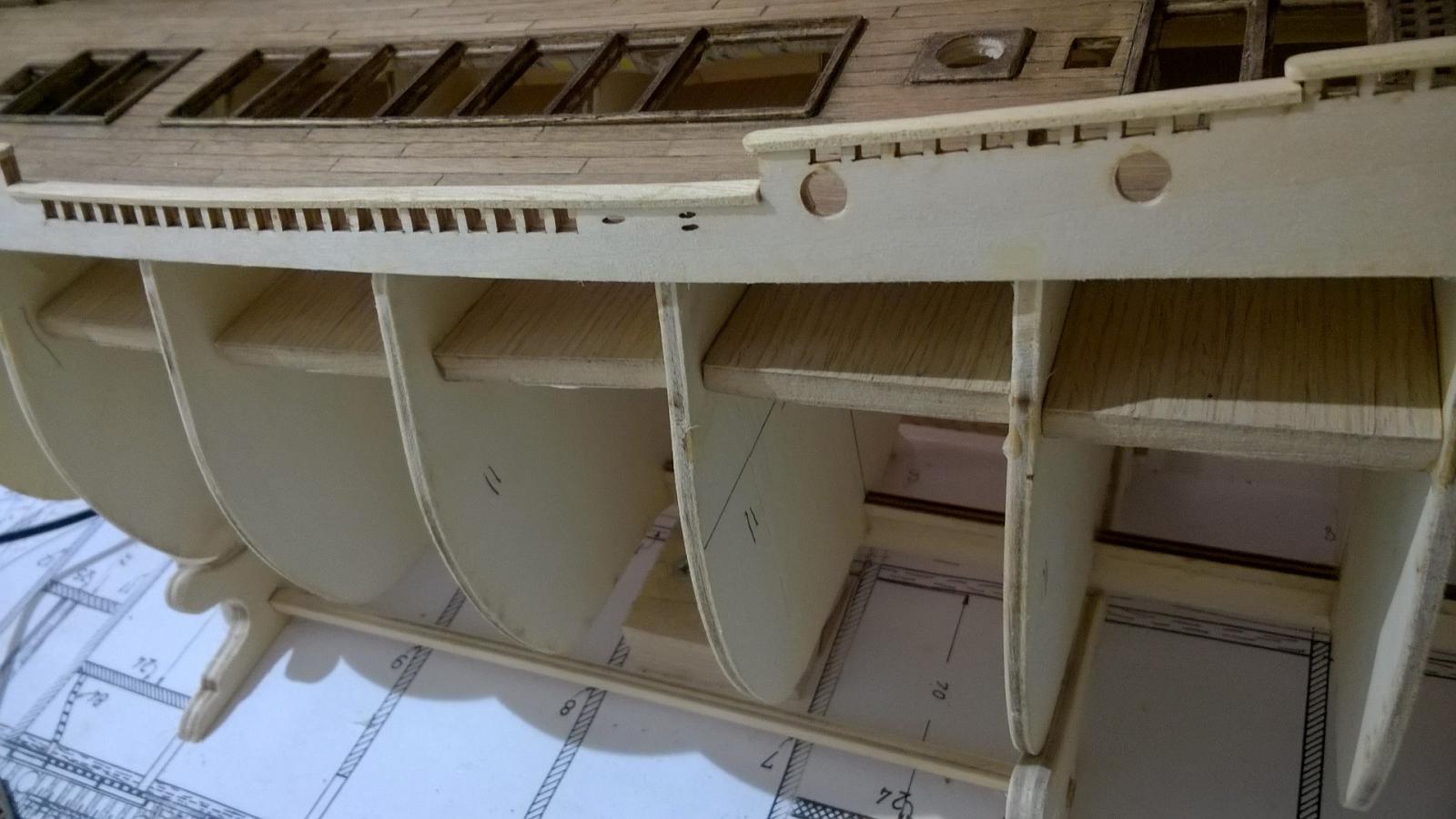
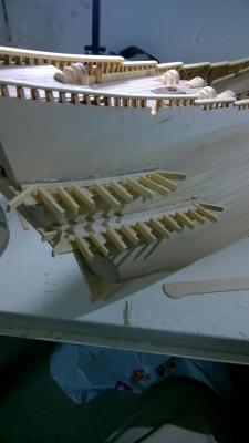
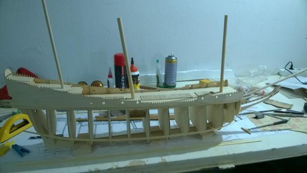
After glueing about 200 more 1 mm x 1.5 mm "matchsticks" to form rail posts fitted to every crenellation in the deck side pieces, I realised that these crenllated edges were very fragile. I broke a couple and had to superglue them back in place again. So I decided to fit the lower side rail pieces before planking the hull, to "protect" the work done so far.
- 86 replies
-
- 3
-
-
- billing boats
- wasa
- (and 1 more)
-
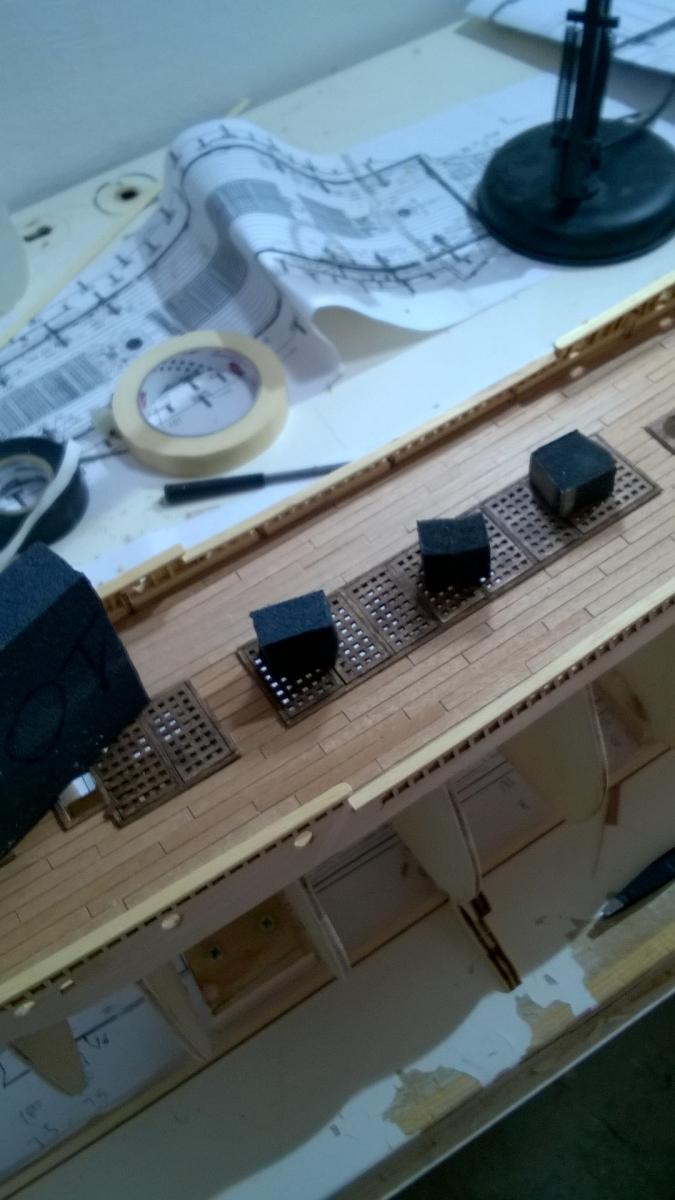
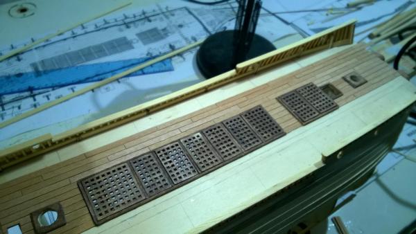
Here's a shot of the main deck after filling with dark oak wood putty, sanding and staining with light oak water soluble wood stain. I used a cloth, not a brush, to apply the stain. I used dark oak wood stain to color the gratings and deck hatch sides. The little black cubes are pieces of a foam sanding block that I cut and used to sand the deck.

- 86 replies
-
- 3
-
-
- billing boats
- wasa
- (and 1 more)
-
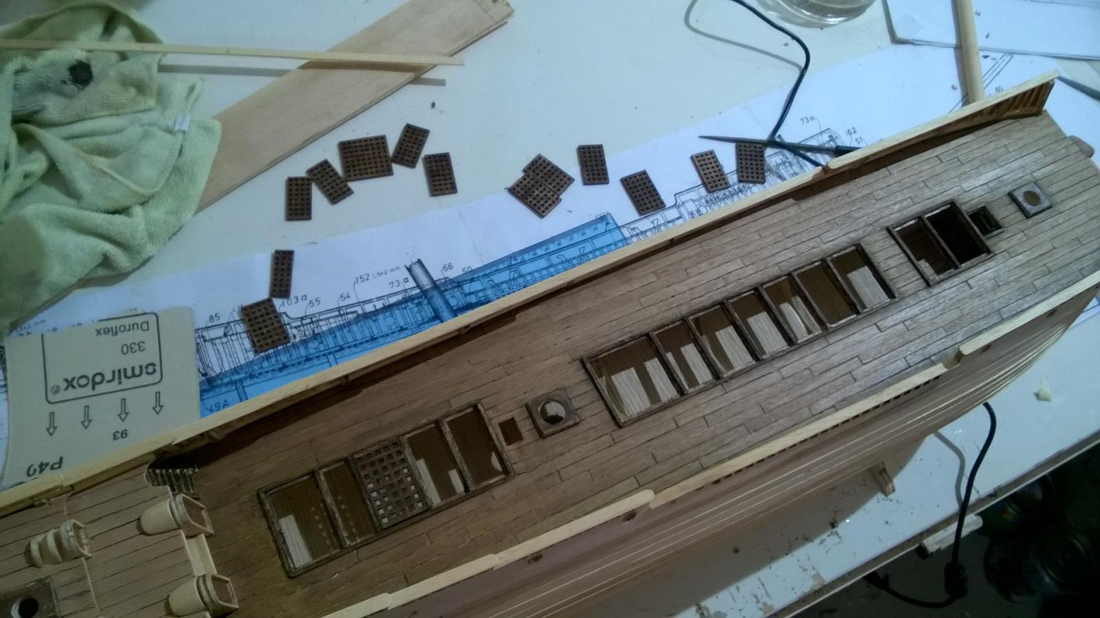
And then there's the fiddly job of glueing tiny "match stick" pieces of 1 mm x 1.5 mm strip to form the sides of each hatch. Again I used PVA glue not Cyano, because I used my fingers to position and align every piece and I didn't want to glue my fingers to the deck. I don't like the end result because the hatch sides come flush with the hatch gratings. When I looked at the "real" Vasa, I realised that the gratings were an inch lower than the top of the hatch sides. So, it would be far better to make the hatch frames from 1 mm x 3 mm strip. In future I will cut off the 1 mm x 1.5 mm strips and redo the hatch frames with 1 mm x 3 mm strips. You can also see the deck planking that I've added but not yet sanded and finished in this picture. I used 6 cm planks which at a scale of 1:75 represent 4.5 m planks on the full size ship. I think the deck plank pattern on the Vasa was faily "random" but I used a pattern of offsets that repeat every 4 planks, the pattern being 1, 0.5, 0.75 and 0.25 offset in sequence. I laid each plank with a very small gap that I would fill later with dark oak color water soluble wood putty.
- 86 replies
-
- 4
-
-
- billing boats
- wasa
- (and 1 more)
-
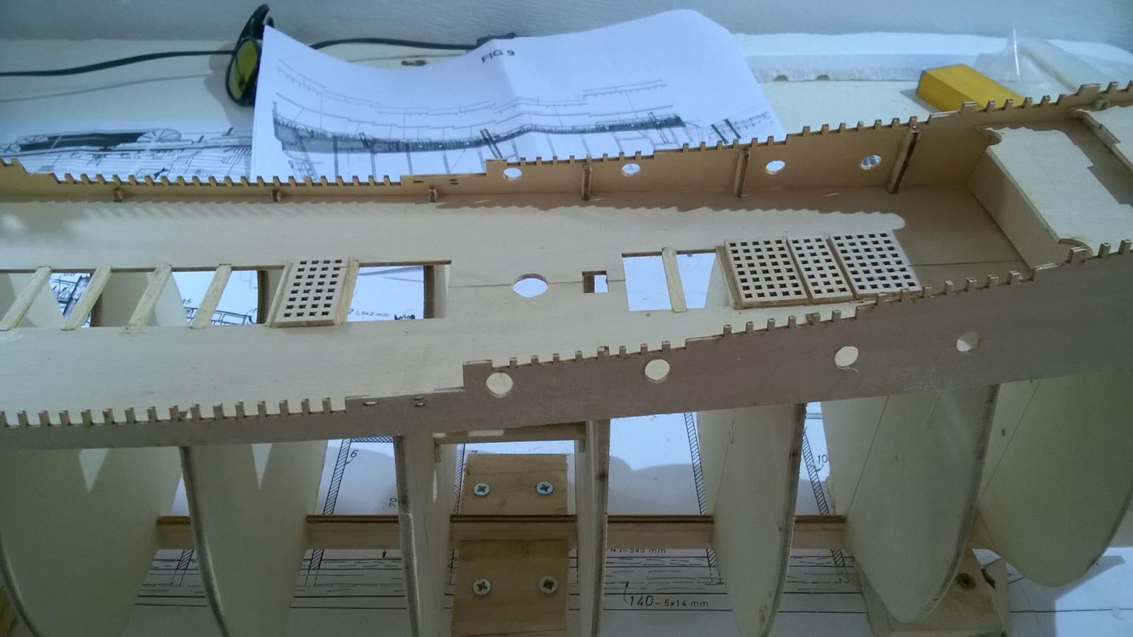
This next pic shows the support pieces being added for the main deck gratings. The slots in the plywood are 5 mm wide and you use strips of 7 mm timber to form the cross pieces. Sanding each corner at a 45 degree angle allows the 7 mm timbers to be pressed into position where they are self-supporting while the glue sets, in this case I used PVA because I used my fingers to ensure the upper surface of each cross piece was exactly flush with the main deck.

- 86 replies
-
- 2
-
-
- billing boats
- wasa
- (and 1 more)
-
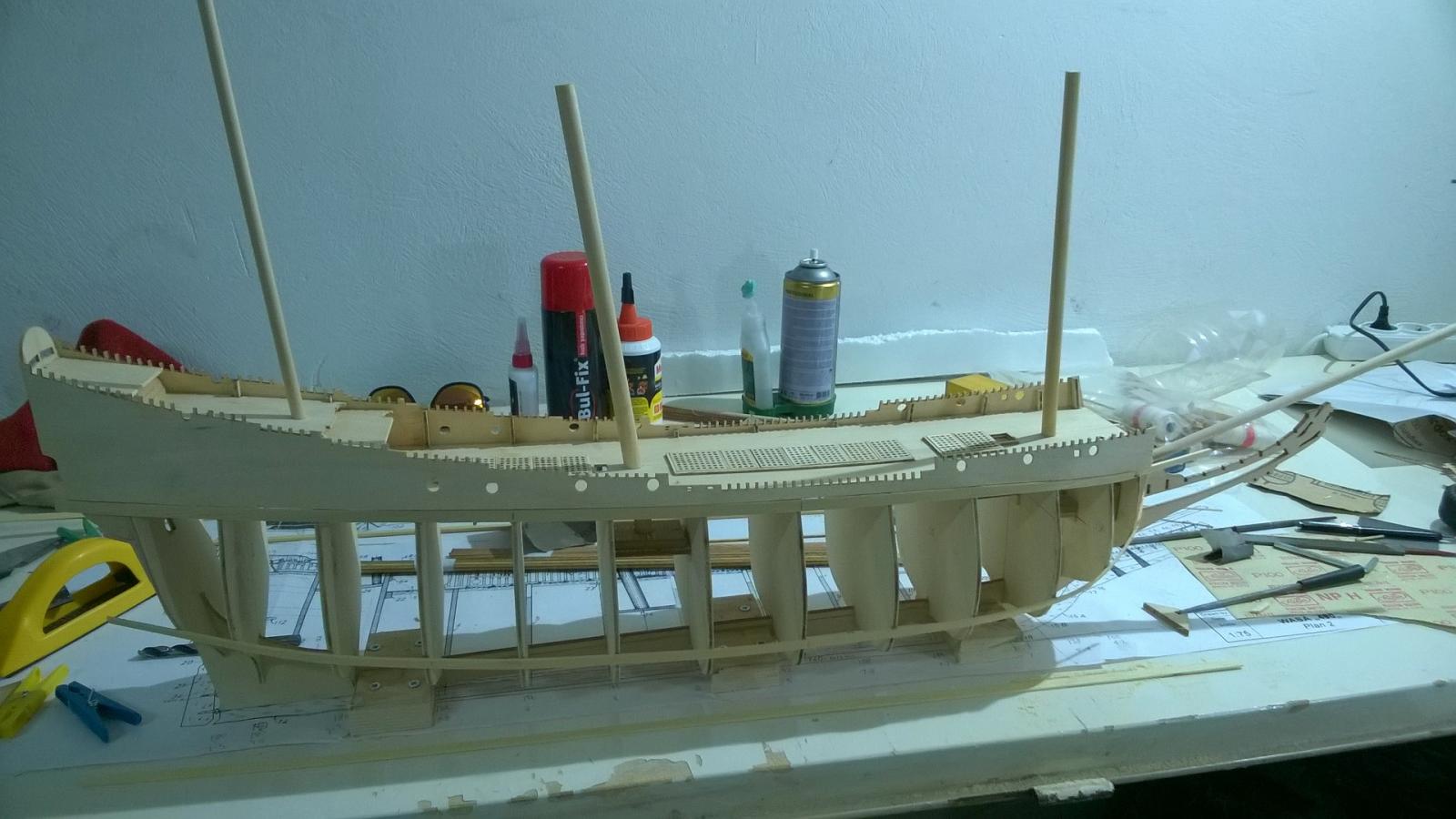
I had followed Billing Boats' instruction leaflet when glueing in place the mast bases at the correct position. But then I realised there was nothing to accurately locate the masts later on when I wanted to glue them in place. So I made some supplementary blocks out of fiber board, drilled them at the correct angle for each mast, "dry fitted" each mast in the fiber board block, aligning each mast with the plans on my worktable, and then used PVA glue to fix each fiberboard block to each mast base. There should really be an additional ply piece supplied in the kit to do this. It's not immediately obvious in any of the instructions provided by Billing Boats which piece of dowel rod is the correct one to use for the lower section of each mast. The deck holes are approximately the correct diameter, do not enlarge any of them by more than 0.1 mm! The main mast is 12 mm, obviously. Then there are two 10 mm dowels supplied in the kit, one of which is the lower section of the foremast. There is a great temptation to use the second 10 mm dowel as the rear mast base, but that is wrong! The rear mast is an 8mm dowel, as is the bowsprit mast. The second 10 mm dowel is part of the main mast assembly to be used later.
- 86 replies
-
- 3
-
-
- billing boats
- wasa
- (and 1 more)
-
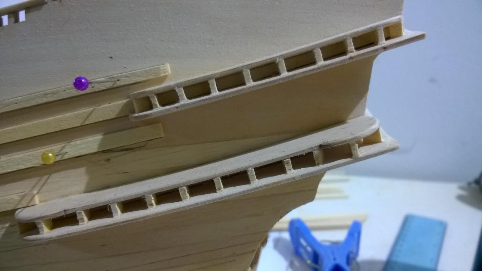
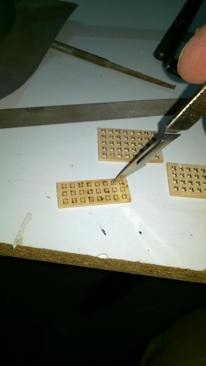
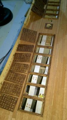
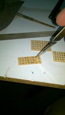
The Billing Boats kit contains many laser cut parts on plywood sheets, but it's annoying that every laser cut stops short of the "finish line" by between 0.5 and 1 mm. In the case of the deck hatch gratings, it was very frustrating to have to cut the final 0.5 mm of every little hole and then use a needle file to clean up each hole afterwards. I'd have much preferred Billing Boats to complete the laser cutting job with these little holes! As it was, I used a surgeon's scalpel with a new blade. But it was nearly impossible to prevent some bits of the plywood from de-laminating and spoiling the finish of the gratings. It then took ages to glue tiny scraps of wood to repair the areas of damage where the ply had de-laminated.
- 86 replies
-
- 4
-
-
- billing boats
- wasa
- (and 1 more)