RobZorba
-
Posts
90 -
Joined
-
Last visited
Content Type
Profiles
Forums
Gallery
Events
Everything posted by RobZorba
-
 Michael, Meticulous and ingeneous work for a very complex part of the ship! Many thanks for pioneering and for sharing the details of what you've done. It will help me when and if I get that far! Rob
 -
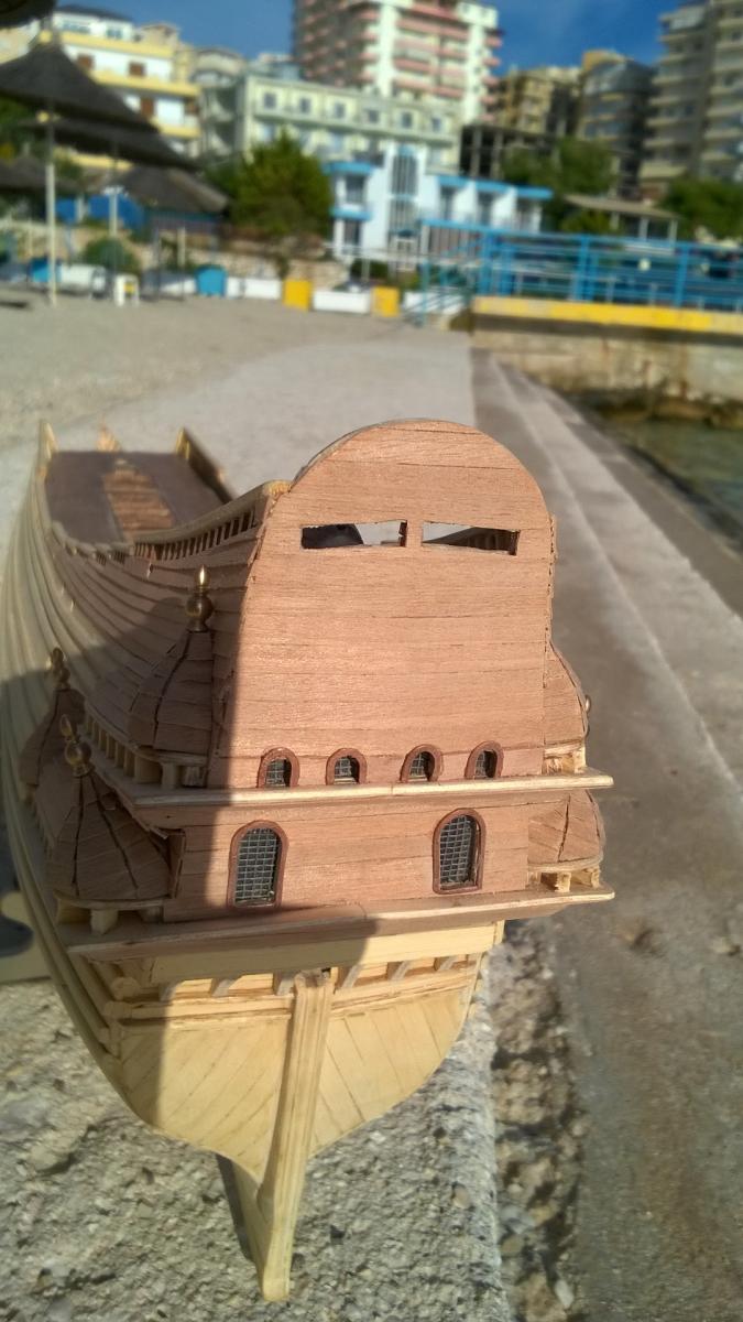
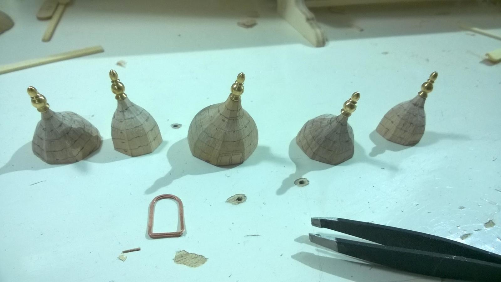
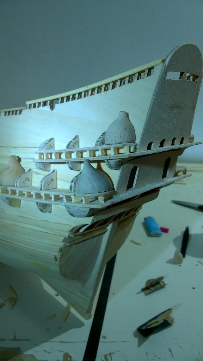
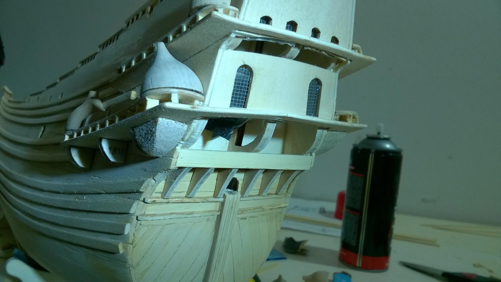
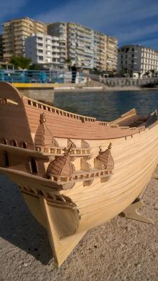
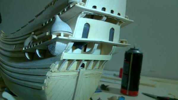
A couple of pics in daylight ... progress so far ... We had to angle the octagonal towers to point outwards at an incorrect angle. This was caused by the earlier "error" causing the two galleries to be 7mm closer together than they should be. We made window frames from copper wire, hammered flat ...

- 86 replies
-
- 3
-

-
- billing boats
- wasa
- (and 1 more)
-
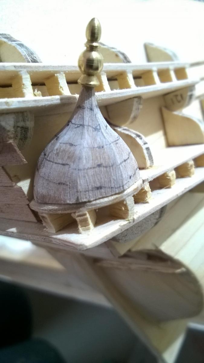
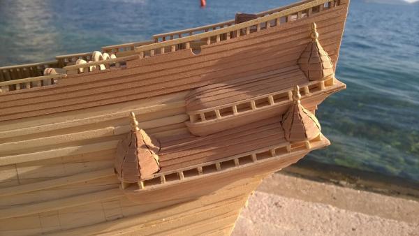
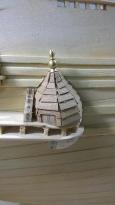
After much adjustment of angles, managed to make everything fit and now proceeding with planking the galleries and finishing the stern. I decided to add some "packing pieces" before planking the gallery top and bottom. Also I "squared off" the conical towers into 45 degree sections because the Vasa's towers were octagonal, not conical per the Billing kit. I then decided to "plank" the conical towers the same as the full-size. It's been quite a lot of fiddling around for the last 2 days to progress these details.
- 86 replies
-
- 5
-
-
- billing boats
- wasa
- (and 1 more)
-
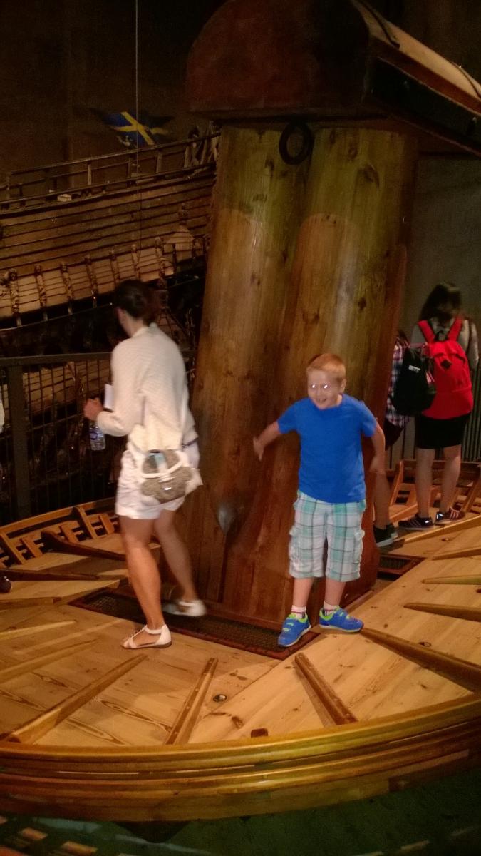
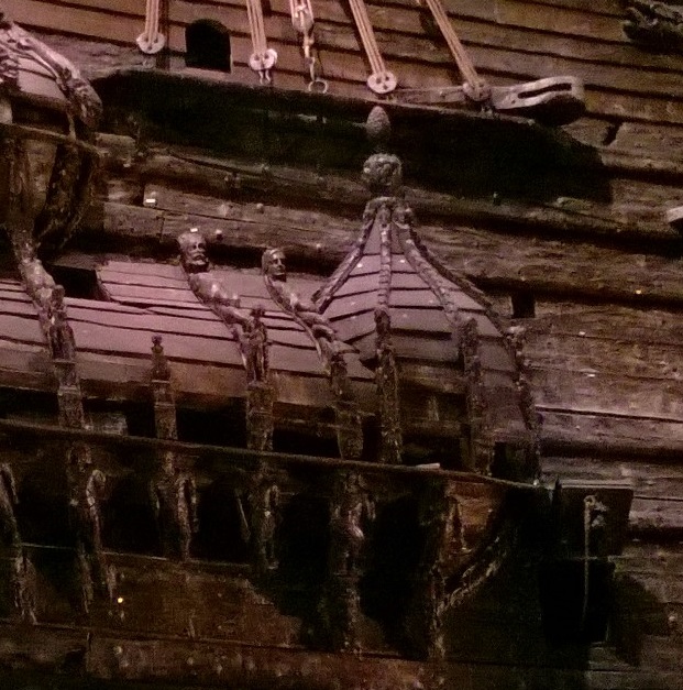
Hi Michael, In case it helps you, the Vasamuseet have a reconstruction of one of the crow's nests which I think is a fairly recent addition in the museum. I attach a picture I took. Forgive me if you have this already ...

-
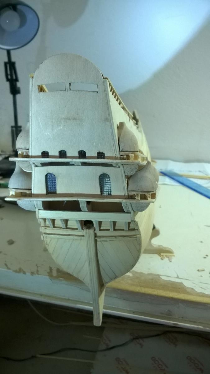
Thanks! ... too late now to tear the model apart and rectify the errors, so Turi and I are continuing with the build by adjusting parts on the galleries to avoid "collision" as far as possible. The two lower gallery towers are now adjusted to point outwards, looks a bit wrong, but I think it's the best we can do in the circumstances ... the cladding of the lower part of the upper gallery will merge into the cladding of the upper part of the lower gallery ... will do better next time ...

- 86 replies
-
- 1
-
-
- billing boats
- wasa
- (and 1 more)
-
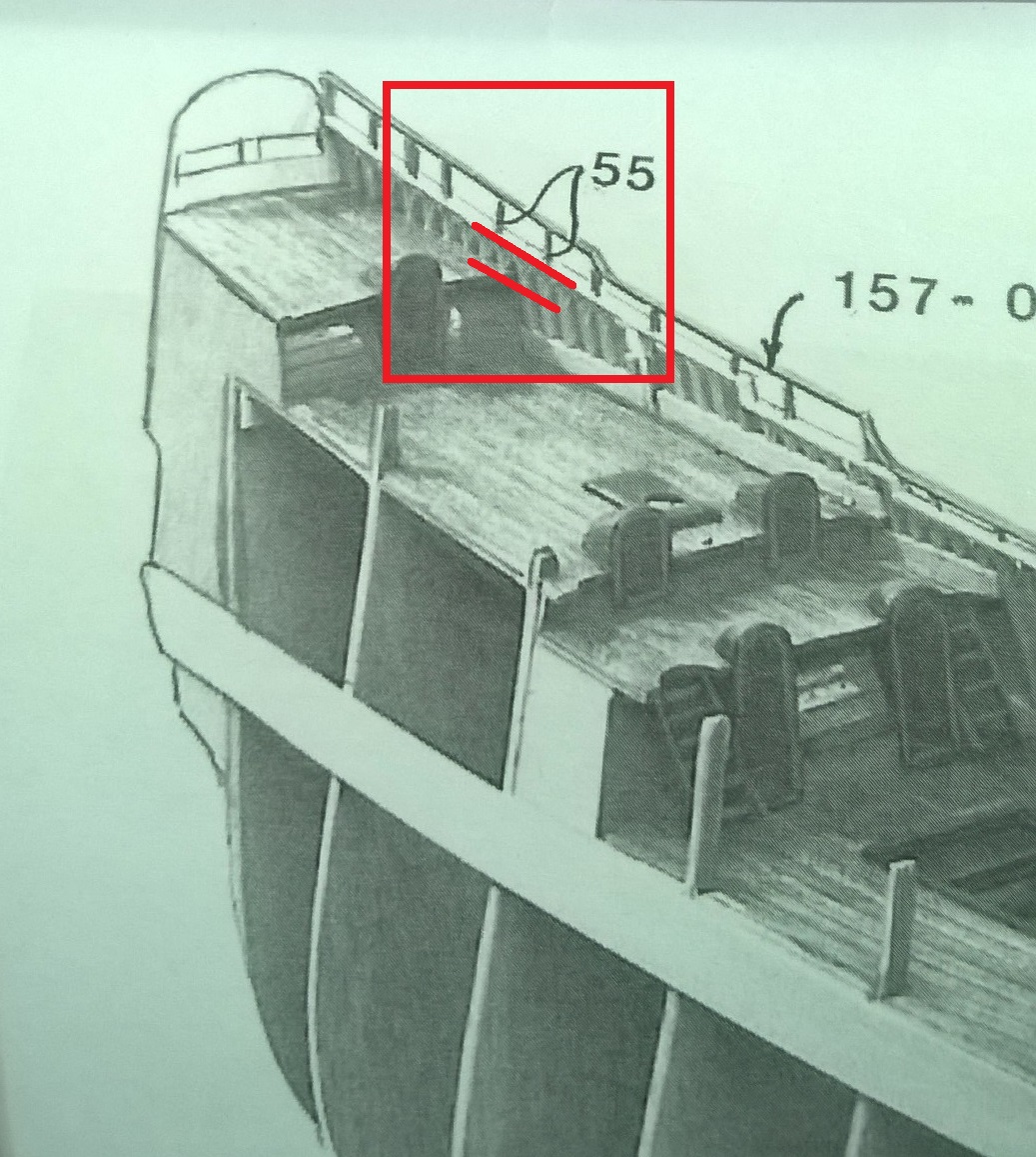
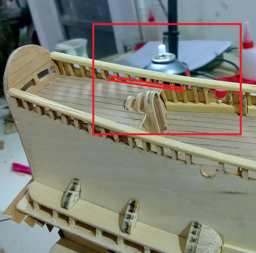
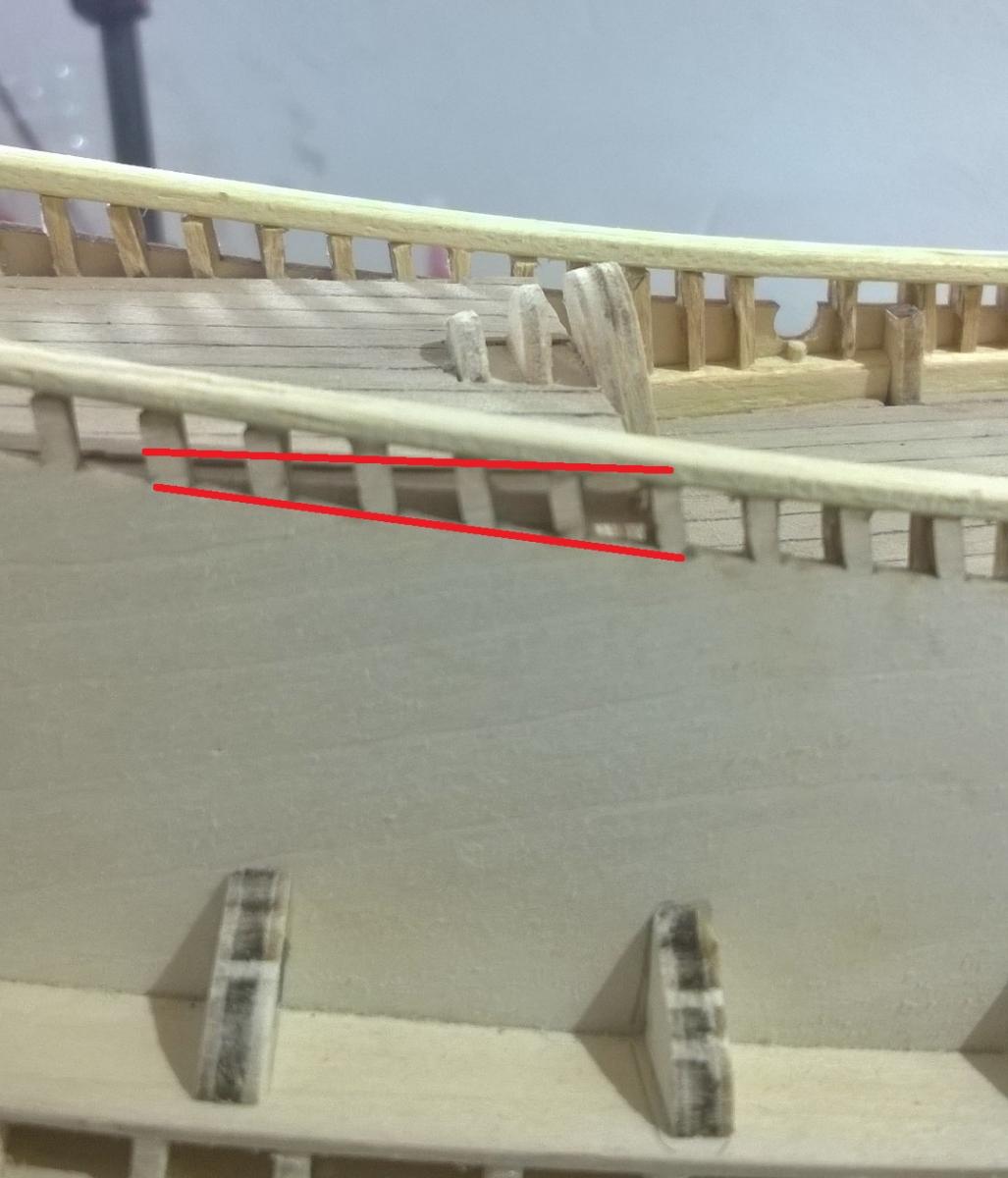
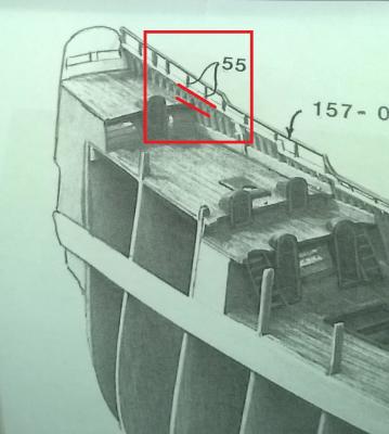
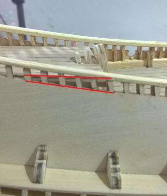
After much investigation of what I initially believed to be a Billing Boats kit design error, I conclude that it is assembly error on my part. Here is an illustration from the Billing instructions, note that the ply piece forming the railings is above the stern deck by about 4 mm. Here's the equivalent picture of my model, the equivalent line on the ply side piece is 3 mm below the stern deck: So, I think the most likely "error" of 7mm was introduced somehow by me very early on by positioning the ply side pieces 7mm lower than they should have been, and then following this by setting the upper stern ply piece also 7mm lower than it should have been positioned. I hope that by exposing my "mistakes" in this build log, it will assist other builders to make sure these ply side pieces are placed correctly. If you get it wrong, then the upper and lower stern galleries will "collide" and cause all sorts of problems later on.

- 86 replies
-
- 1
-
-
- billing boats
- wasa
- (and 1 more)
-
Incidentally, the digital plans published by the Vasamuseet are incredibly helpful. I downloaded the set of them, I think 7 large sheets in total. I wish I had found these before starting my build of the BB Vasa. I will ask one of the architects in Sarande if they will print the set on their drum printer, scaled to 1:75 per the BB kit.
-
Yep Michael, your changes to the Corel kit look perfect. I am cross with myself for "believing" the BB kit would not have a similar problem. Why the heck did I not check it more carefully before I started assembly and planking? The strange thing here is that with Corel it is the lower Gallery that is too low, and the upper gallery is OK. With BB, the lower gallery is OK but the upper gallery is too low. So ... Corel's Vasa needs a butt lift ... and BB's Vasa needs a breast lift ... :-)
-
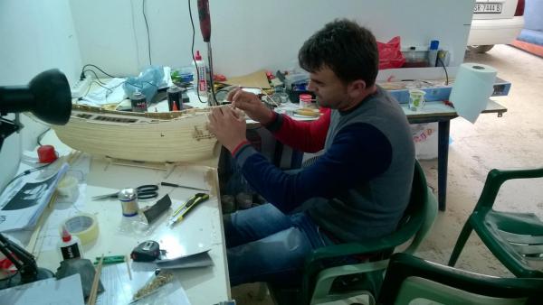
Thanks Mark and Michael I will not tear the BB Vasa model apart this time, but I will get another few BB Vasa kits soon, and make these modifications with some scratch built parts to correct this error, and also build scale upper and lower gun decks with improved canon fixings - perhaps similar to how Euromodels do it with the RW you are building, Mark. I am very interested to see the Euromodels frame parts and how the canon deck assembly comes together. As you know, one of my goals is to build a team of two or three Albanian "experts" who can deliver high quality ships in display cases for sale in Europe and Eastern Bloc countries at reasonable prices. I care nothing to make a profit myself, but instead wish to provide a reasonable wage for a few hard working Albanian people who are desperate for jobs. I have my first "employee" named Turi who is working 4 hours every day, and who is meticulous and passionate about the exact scale details. Here is a pic with Turi working on the planking of the stern ...
- 86 replies
-
- 3
-
-
- billing boats
- wasa
- (and 1 more)
-
Nick, Fantastically accurate work, beautiful model and really good pictures. Thanks a lot for sharing your build log and hints and tips with us! Best, Rob
- 84 replies
-
- 1
-
-
- finished
- caldercraft
- (and 1 more)
-
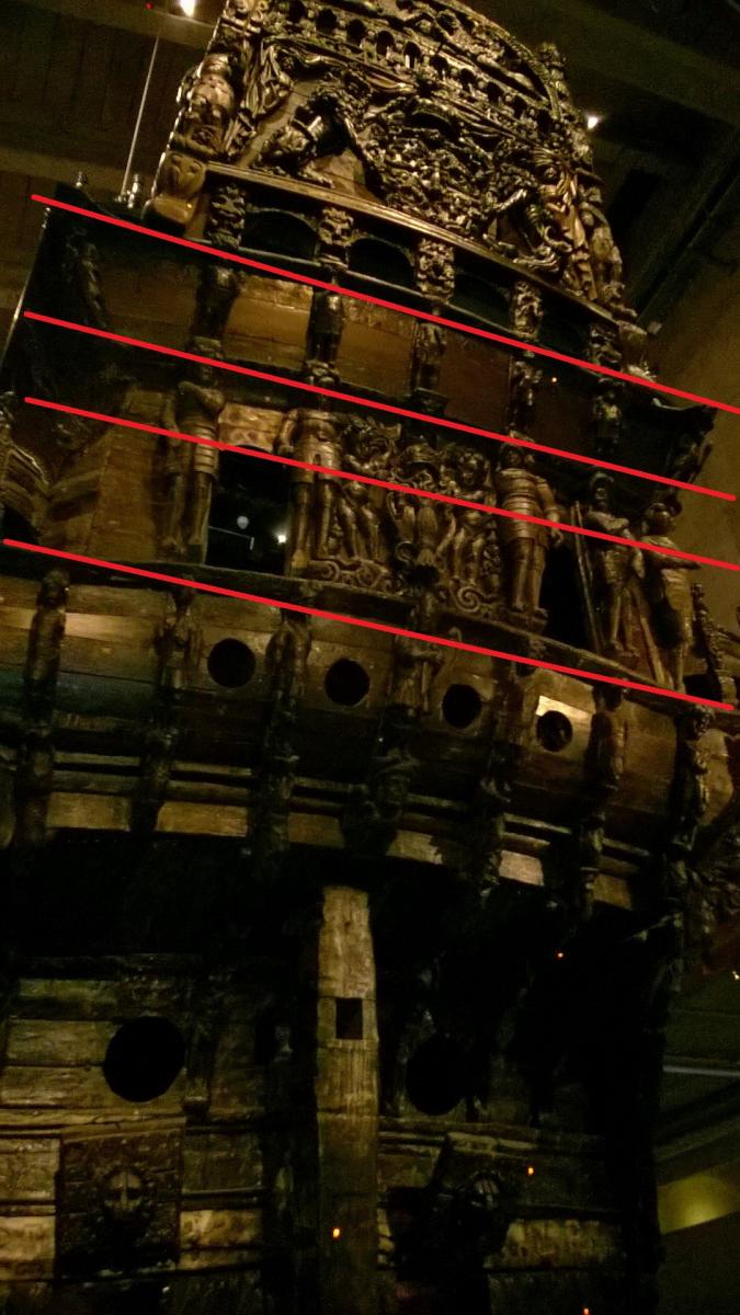
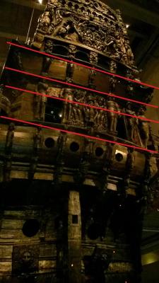
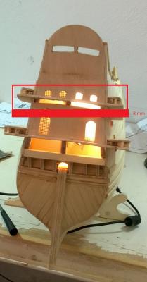
There is a discrepancy in the Billing Boats kit between the model and the full-size. The discrepancy results in the upper and lower stern galleries being positioned too close together, causing a "collision" between parts in the two galleries. The discrepancy also occurs in the plan and elevation views of the Billin Boats kit. Let's look at the stern, where the gallery bases are fitted ... The upper gallery on the Billing kit should start about 8 mm higher up the stern, in order to be correctly positioned. This will involve a redesign of the Billing Boats stern, plus a number of laser cut pieces attached to the port and starboard sides of the kit. Because of the design error, the user has to modify the lower gallery conical towers to "point outwards" at a stupid looking angle, to avoid "collision" with other parts of the model. So far, this is the most serious design error in the Billing Boats kit that I have found. It is too late for me to correct it without starting again with a new kit. Unless Billings are persuaded to fix this error, I will scratch build the stern another time ... using the Vasamuseet digital drawings ... At this point I'm feeling pretty depressed to have discovered this serious error in the model I am building ...
- 86 replies
-
- 1
-
-
- billing boats
- wasa
- (and 1 more)
-
Reshaped the conical towers to be octagonal, and commenced gallery and stern planking .. When I visited the museum, it seemed that one of the gallery towers has an extra "open window" in it, and I added that "feature" only to discover that it was a "missing plank" on the full ship, and not an "open window" at all! So I'll plank that bit again tomorrow ...


- 86 replies
-
- 1
-
-
- billing boats
- wasa
- (and 1 more)
-
Hi Mark, The way you assembled this seems very innovative to me. A question: how did you manage to glue the bulkheads to the keel with the decks in place? Individual bulkheads could not be removed with the decks in place. My guess: did you first fix all the bulkheads together by fitting the stringers and extra supports, then lift the bulkhead and deck sub-assembly away from the keel, apply glue to all the keel slots in one go, and then press the keel back into place? Also, I believe the Euromodels/ Como kit provides half cannon and false canon posts for the lower decks. Will you use those, or will you make complete cannon for the lower decks and replace the half cannon provided by EM? I am very impressed that EM provide all decks. Have you thought of providing some kind of "cut out" view in part of the hull, maybe only from one side of the model, so a part of all the internal decks can be seen, perhaps with some deck fittings / scratch built ladders / rigged canon etc for the visible area? For me, when I can afford the RW, I think I would use a 2mm perspex sheet as a "window" between two or three of the frames, and cut "gun ports" into it, as well as fixing part of the canon rigging and gunnery accessories to the side of the perspex. Perspex can be moulded quite easily by gentle heating and applying pressure where it needs to bend. If you haven't seen it already, there is another build in progress on another forum, build log here
- 652 replies
-
- 2
-
-
- royal william
- euromodel
- (and 1 more)
-
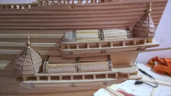
Fitted many of the gallery parts today. The Billing Boats kit does not show balsa blocks for the junction between the galleries and the stern planking. But without blocks, it would be a hard job to join the 90 degree corner of the planking properly. So I made some corner pieces. The preparation for planking is not quite complete yet, I will chamfer the conical corner towers so the planking will lie flat. The measurements for cutting the conical corner towers in Billing instruction sheets were wrong for the lower gallery. In fact the rearmost lower gallery corner tower would not fit below the upper gallery with the measurements Billing provided. And when I studied some of the Billing photographs, I could see they had grafted in an extra ply spacer because they had cut the cones to the wrong shape. An additional 6 mm needed to be removed from the lower surface compared with the Billing dimensions. Unfortunately, I'd already cut four of the planking strips to "fit" the parts made with Billing oversized measurements before I realized it was not correct. So I had to "graft" some replacement planking strips.


- 86 replies
-
- 4
-
-
- billing boats
- wasa
- (and 1 more)
-
Michael, Thanks a lot for your reply, I 'm glad to hear that the Billings kit is fairly accurate! It was also good value at about 250 Euros.
-
Michael, thanks for your valued reply. I am surprised you said "Billings" was a wise choice ... why not "Corel" ... which is the ship you are building? Also it was not a well informed choice on my part. I visited the VasaMuseet, saw the Billings kit and purchased it. They did not sell wooden kits from other manufacturers, so I guess they made the choice for me!
-
Hi Mark, I will follow your build log with great interest, it is a possible future model for me also (but currently out of stock and I have much work remaining to do on the Vasa). The RW model looks really nice - because the upper gundeck is provided, their metal castings for decorative pieces are superb, and the quality of instructions and plans are high. I see that the castings are sold separately and cost more than 60% of the total price of the kit. Are they cast in gold? :-) Joking aside, I wish you much success and great fun with the build, matey! Best regards, Rob
- 652 replies
-
- 1
-
-
- royal william
- euromodel
- (and 1 more)
-
Fantastic work Michael. You are an inspiration to newbies such as me building only my second ship. I can see you are "into" the rigging in a big way. From the images it looks like a rat's nest with ropes tied to the bowsprint mast everywhere. How do you manage to sort it all out? Maybe in my ignorance I imagined I will assemble all the masts and then fit one rigging rope or rigging piece at a time, building it gradually. Is that a bad way for a newbie to start on rigging? Thanks, Rob
-
@Mark / marktiedens@ and @Michael / md1400cs@ Thank you both for reading my newbie build log, and for the helpful links you sent me. I have looked through your own build logs and the quality and skill shown in your work is outstanding. I hope to improve my own skills to be able to produce higher quality models, and for me that goal is as a hobbyist and perfectionist. But I also have a conflicting motive. I am "training" a couple of Albanian craftsmen who wish to produce model ships (built from kits) commercially. There is tradeoff between quality and cost, and they will be doing this to earn a living. What I am trying to find are ways to improve the "quality" of models bult from standard kits such as those from Billing Boats without adding hugely to the time taken to build each model. Each model must be built to an acceptable standard with a "cost" budget of no more than 400 hours work, plus the cost of the kit and materials used. I believe there is a market for such models in Europe - especially Scandinavia, Germany, Austria, Belgium etc, but the selling price needs to be 2000 Euros or less including display cabinet. Here in Albania, craftsmen consider they are doing very well if they earn 3 Euros per hour. The typcal wage for craftsmen is 10 Euros per day. Have either of you produced ship models for sale, and if so, what is the "tradeoff" between quality and cost (hours worked) that you advise?
- 86 replies
-
- 3
-
-
- billing boats
- wasa
- (and 1 more)
-
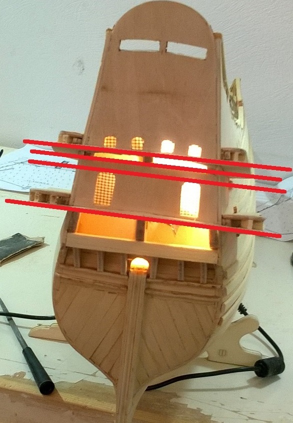
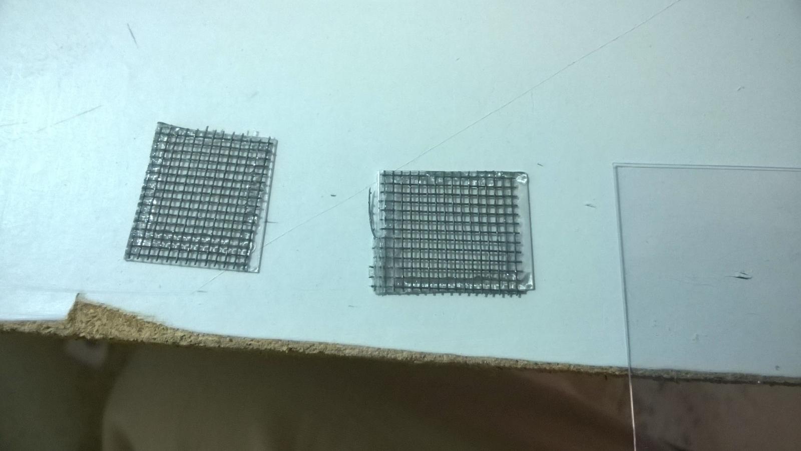
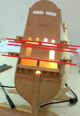
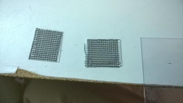
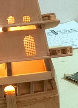
I found a great way to make the "window bars" to simulate leading in the captain's cabin windows. I used a small piece of black mosquito net, the sort that is fitted to double glazing fly-screens. I glued the mosquito net using Cyano (without accelerator) to the front of the perspex, making sure the glued area would not be visible. Then I stuck the perspex windows in place, again using Cyano, making sure the "bars" were vertical. The 3M LED lighting strips I fitted are a bit too bright, especially in the area of the captain's cabin. It was a dead easy and prewired lighting solution ... but I need to dim the lights quite a bit ... they even shine through the timber of the hull and that's not right! Before I finish the model I will fit a resistor in series with the 12v power supply to limit the current to the 3M lights. Anyway, now the "window bar" solution is in place I can proceed with the rest of the work on the stern. The paints I ordered will arrive next week, and I'm looking forward to doing some decorating!
- 86 replies
-
- 3
-
-
- billing boats
- wasa
- (and 1 more)
-
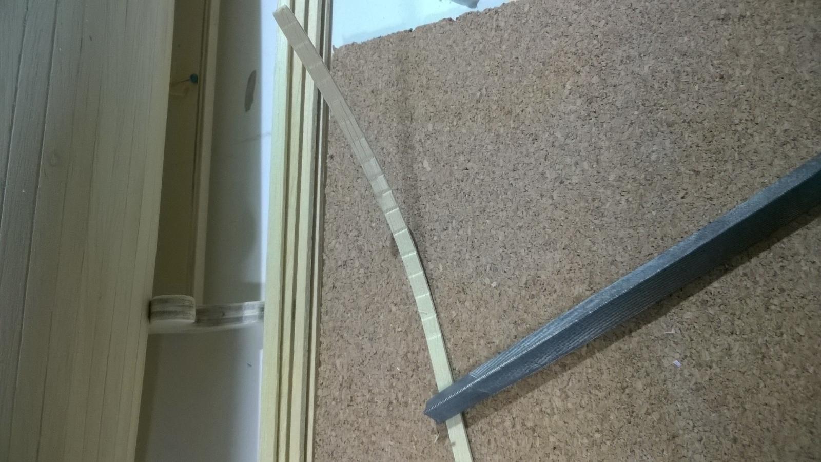
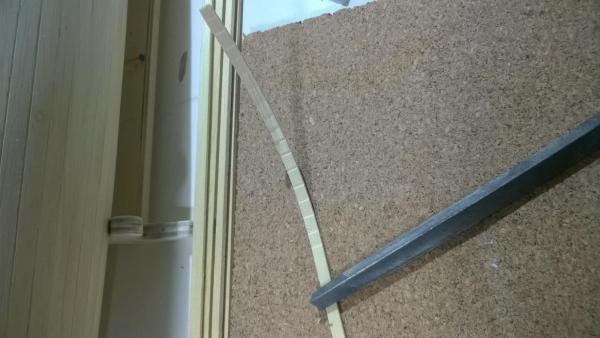
Here's my method for bending planks. It's dead easy and requires no special tools apart from a robust triangular file. I lay the plank on a piece of 2mm cork matting below which is my flat and level worktable. I press the vee of the file into the strip, rolling the file slightly from left to right as I do it. The strip curls beautifully and there is never a break. I don't have to soak the planks or do anything else.
- 86 replies
-
- 4
-
-
- billing boats
- wasa
- (and 1 more)
-
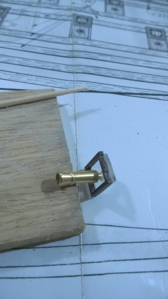
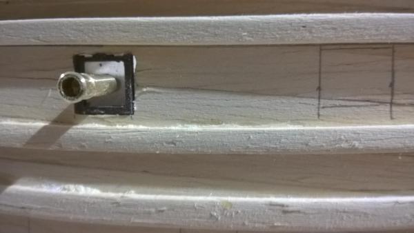
My "ultra quick" Gun Port modification (sorry for some repetition from an earlier post) ... I glued a small square of 3 mm acrylic (safety "glass") to the rear of each plastic gun port frame. I drilled the center of the acrylic to fit the dowel on the rear of the stub cannon. I will paint an area of the acrylic matt black to simulate the gun carriage. The window frame will be painted red with gold trim. I will paint the canon with an unevenly stirred mixture of Humbrol antique bronze and gunmetal paint. I will stick the completed assembly using Cyano into the gun port openings, using the canon as a "handle" with which to position the frame accurately into position before "kicking" the Cyano with accelerator. I will cut the remaining openings one at a time, because I want to insert and glue one gun assembly and then cut the next one. This will minimise any risk of hull planking moving out of position.

- 86 replies
-
- 4
-
-
- billing boats
- wasa
- (and 1 more)
-
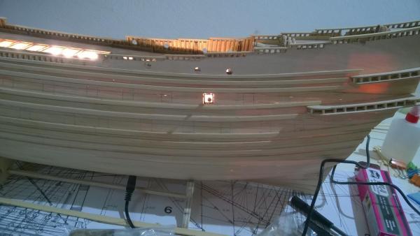
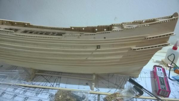
Finished the port side cladding planks, and marked the gun port openings. I cut the first opening as a test.
- 86 replies
-
- 5
-
-
- billing boats
- wasa
- (and 1 more)
-
Rigging the Vasa .... what color goes where?
RobZorba replied to RobZorba's topic in Masting, rigging and sails
@Mark@ Thank you for a most helpful reply. So, I know what I have to do!