HOLIDAY DONATION DRIVE - SUPPORT MSW - DO YOUR PART TO KEEP THIS GREAT FORUM GOING! (Only 24 donations so far out of 49,000 members - C'mon guys!)
×


hervie
-
Posts
68 -
Joined
-
Last visited
Content Type
Profiles
Forums
Gallery
Events
Everything posted by hervie
-
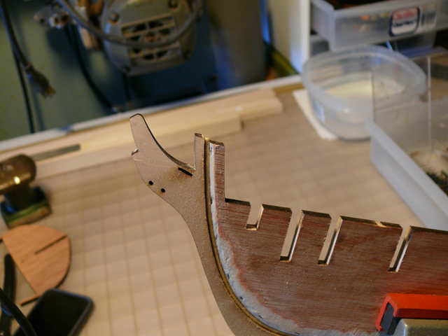
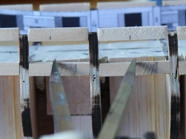
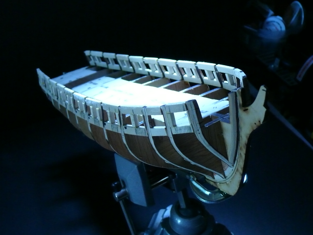
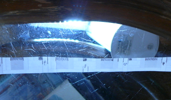
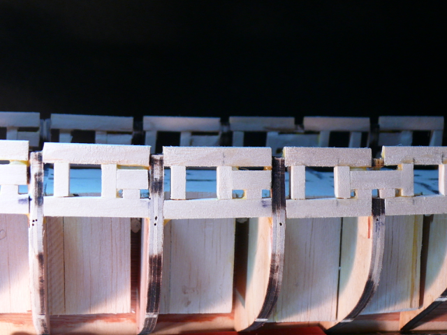
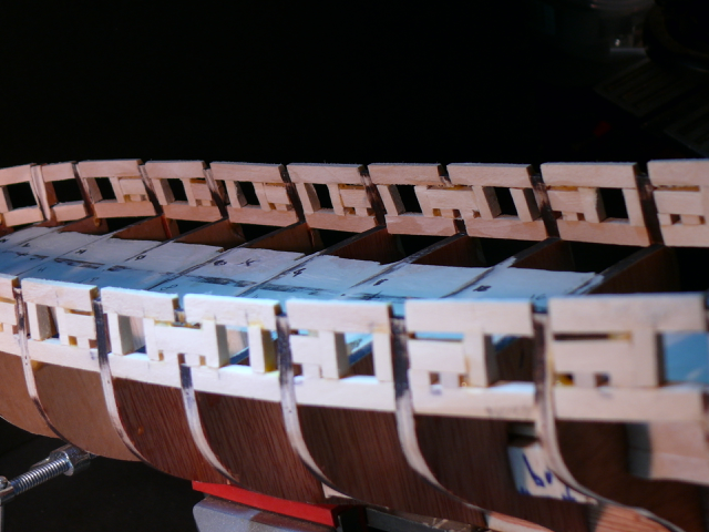
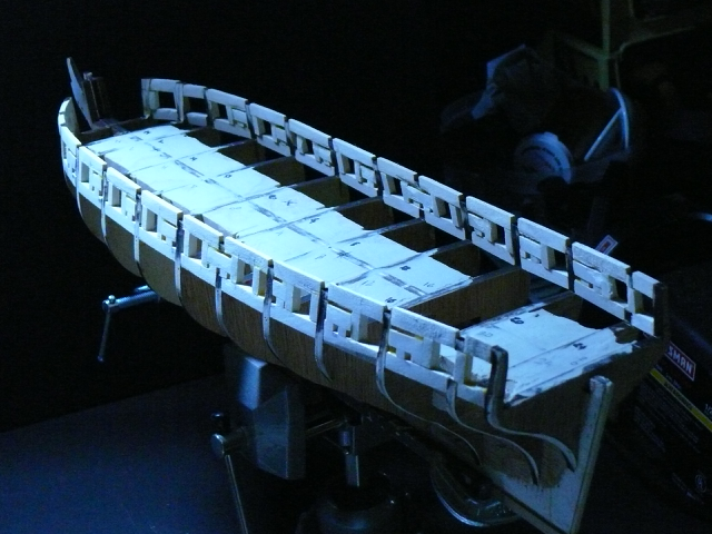
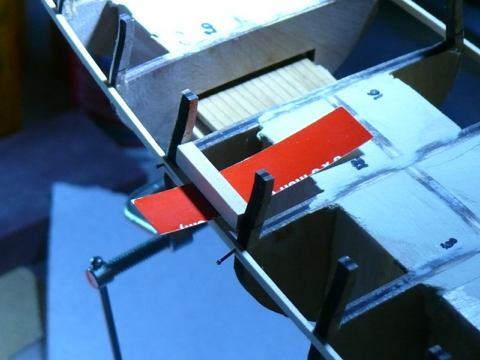
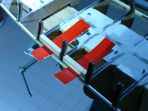
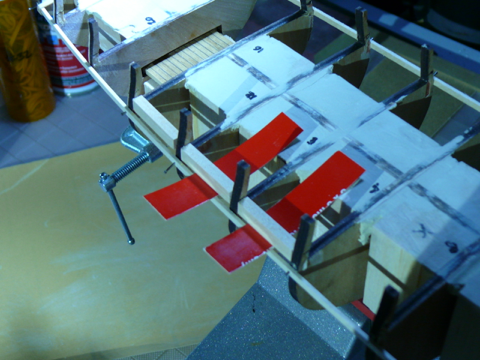
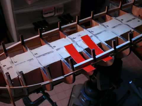
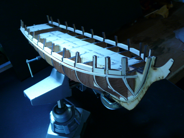
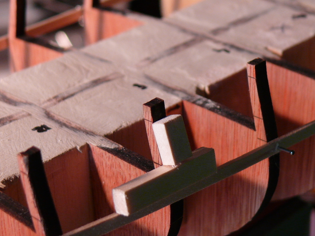
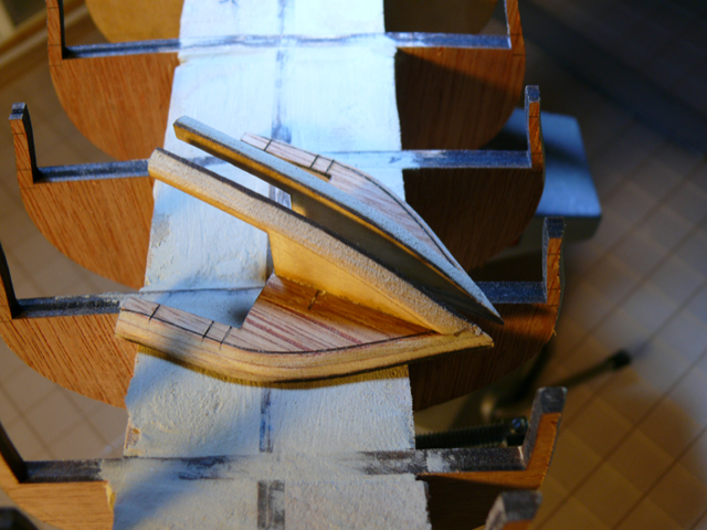
 Gun Ports framing The scale of the kit supplied templates is off, so I scanned a new template from page 2 of the plans. That one is a bit off too (Because of misalignment of my bulkheads), but all that is needed to draw all gun ports is the correct position of just one. Why? Because the distance between gun ports appears to be the same. The position of the gun port close to bulkhead 16 was easy to locate since we know the distance to the bulkhead is 3/16 (the width of the vertical gun port frames). From the plans I obtained the distance between gun ports so all gun ports could be drawn on the model. And the width of the gun ports (15/32) could also be drawn. The gun port where shaded on the sills to avoid making mistakes later on. Lastly the vertical position of each gun port frame was marked on the lintels. It appears from the plans the vertical orientation of the gun ports is perpendicular to the ground (or to the water line) With all gunport marked, the rest was routine cutting and gluing. Here are all gun ports in place before sanding. This time I did wait for all framing to be complete before sanding. I was not sure the structure could withstand sanding at this point. The Sweep Ports I marked all sweep ports using the template produced from page 2 of the plan. After removing the sills from the paper template, the gun ports and sweep ports were traced to the other side of the template. I used a makeshift backlight for that. Now the template could be used for both sides of the ship. After marking the position of the sweep ports on the hull (not shown), I cut 1/8 x 1/8 x 3/16 small pieces to serve as the vertical sides of the waterways. I decided to reverse the suggested order of gluing the sweep ports frames by first gluing the vertical sides (blue) then the top side (red). The top side frames would then simply rest on top of the vertical frames. To properly space the sides of the sweep ports I used a 1/8 x 1/8 wood strip. When all vertical frames of the sweep ports were done, I glued the horizontal pieces for the top side (red frames). To finish the job, I sanded both the outside and the inside of the bulwarks using first the Dremel drum sander, second the hand sander and third the pen sander, in that order. Total sanding time: 1 hour. Here’s a close up after sanding: And here is a picture of the inside and outside of the bulwarks. The completed frames: This completes chapter 3. Onwards and upwards!
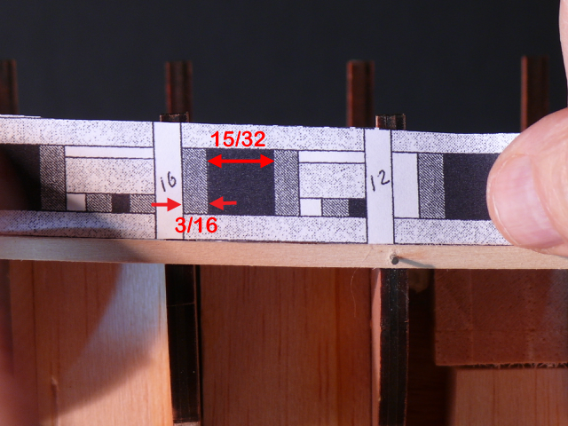

-
I agree, Gary, it is risky, but less so if you hold the hull firmly on your lap with the left hand and work closely and steadily with the right. It would not work (for me) using a vise to hold the hull. Thanks for the tip for the inner bulwark.
-
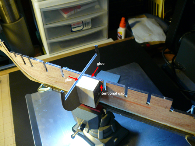
The lintels Before installing the lintels, the sills were sanded. Then I made two 15/32 square cuboids (the size of the gun ports) to assist with the placement of the lintels, as well as with the rest of the framing. As with the sills, the side of the lintels facing the deck was aligned with the interior of the bulwarks. It is a lot easier to sand the exterior than the interior of the bulwarks. Same process for the other side. With all lintels in place, it remained the sanding to do. The manual says: “The lintels should be about 1/8” thick at this point and the sills a little thicker at 5/32” . Here is a view before sanding: For sanding, I tried different tools but settled on a dremel with a sanding drum and a padded hand sander. With the dremel I carefully removed most of the wood, then with the hand held sander smoothed out the unevenness along the hull. I’m finding the dremel with a sanding drum is becoming the tools of choice for this type of tasks. The end result so far: There will be more sanding later as the framing progresses. Next: the rest of the framing.
-
Allow me to climb onboard Brian. For a guy with no experience building wood boats, you're doing an amazing job! I'll be following your build with great interest. .../hervie
- 17 replies
-
- 1
-

-
- syren
- model shipways
- (and 1 more)
-
Thanks Brian, I did check what you did with the masts. Good call! I also read the rest of your log. Very interesting approach. I'll be following it with anticipation ...,/hervie
-
Thanks Gary! Sorry I deleted the post you're responding to Here it is again ------------------------------ Something’s been nagging me for a while: when to drill the holes for the masts? The manual and logs I've seen defer the drilling for after the deck planking and fittings are in place (chapter 17). I am tempted to drill them right now, before the lintels. Why? Because the jig I have in mind for the alignment of the masts sits smack on top of the deck, and with the lintels in place that would not be possible. And because drilling holes after the deck planking and the delicate deck fittings are in place doesn’t seem to be the right time to be playing around with a big drill. The mast holes do not need to have a very precise diameter at this stage. Slightly larger would be better, leaving the final mast alignment for later. I think I may just have talked myself into doing this. Unless someone shares an opinion to the contrary … ---------------------------------- Then I saw Gham's very clever jig for making the holes (p 12) and like him decided to defer the hole making till after the deck planking is done. Hence the deletion of the post. (But I could not resist the temptation of marking the position of the mast holes on the 'deck'. Just in case ... )
-
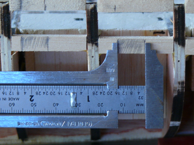
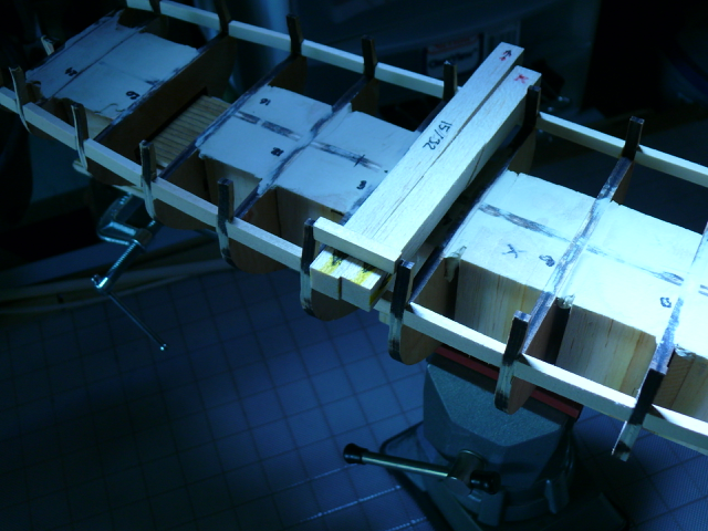
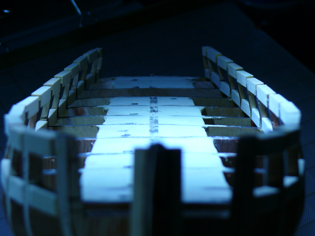
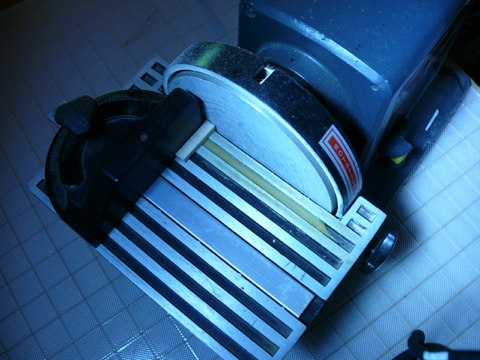
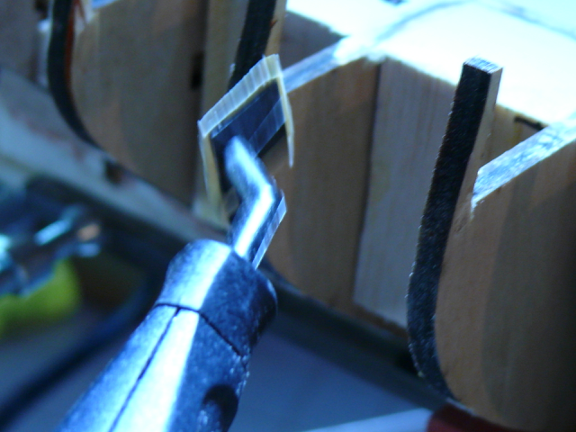
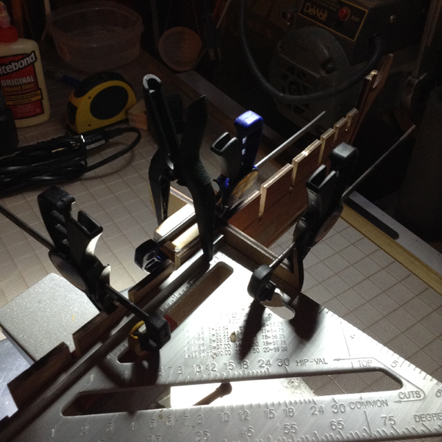
The sills. With the temp battens in place, it’s time to cut, fit and glue each sill. measuring … (slightly longer than the target space) … transferring … Trimming and fitting … starting with the power sander and fine tuning with sanding paper. The power sander chews up wood fast even when fitted with a super fine sanding disk. But for square and angle shapes it is irreplaceable in my opinion. (I know I know, others manage just fine). For maintaining the desired angle in relation to the top of the bulkhead, and the proper alignment in relation to the temp batten, two trips from the cover of a notebook are used as shown below. (Again, the position of my temp battens is not the same as the one suggested in the manual, nor is it necessarily a better one, see previous posts.) first sill ... while the glue for the first sill is drying, here comes the second sill … and by the time the second sill is in place, the jig for the first sill can be removed and used for the third. And so on in leapfrog fashion. Same process for the other side. After about 3 hours, the finished sills before sanding. Next the lintels. Thanks for reading.

-
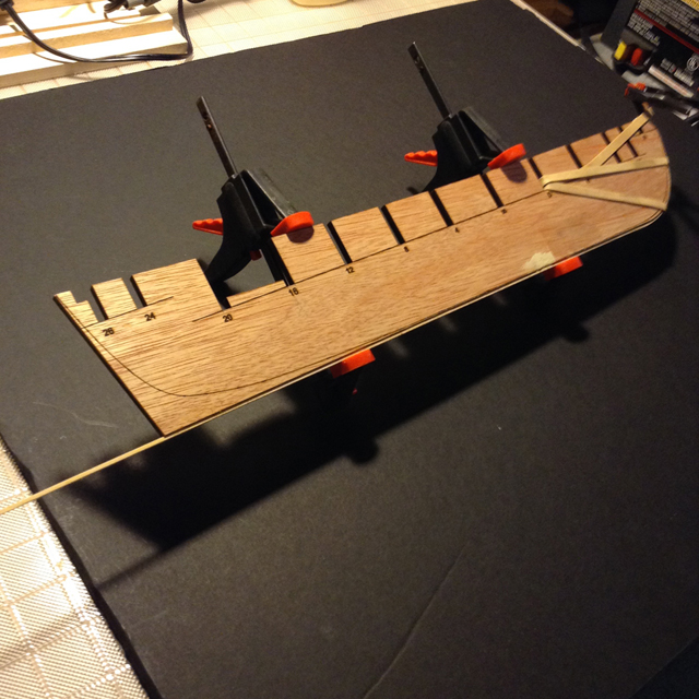
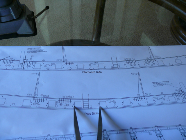
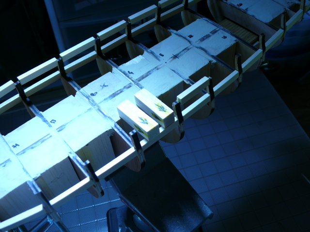
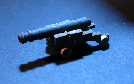
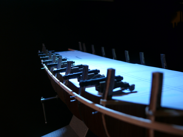
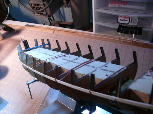
The reworked temp battens For positioning the new battens I used two small 3/16 pieces as guide as I went along. Again I nailed the battens to the hull in a few places in order to be able to wiggle the battens to obtain a smooth curve. A few corrections were required. I also scanned and cut the top view of the deck in page 2 of the plans. I positioned the paper cut on the model’s deck to confirm the plans have the right scale (unlike the supplied templates). The cannons come from an abandoned model of the Constellation. Wrong scale for the Syren, but much better cannons. Another view. I may leave the paper cut on the deck for awhile. Nicer than the filler blocks to look at. This finishes (again) the temp battens. Next: the sills and lintels. Thanks for reading.

-
Just visited Mirabell61 (Nils) log and finished models. I am in awe of the talent displayed in these forums! Pretty humbling ...
-
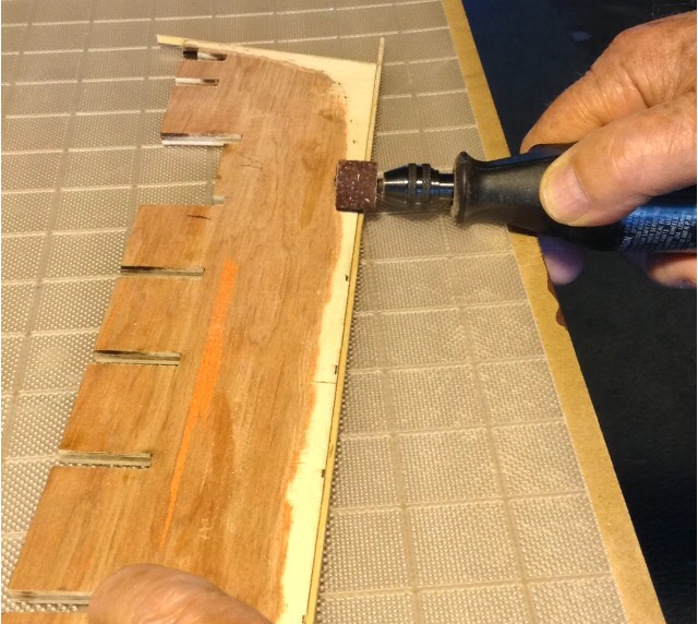
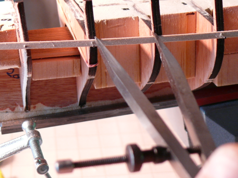
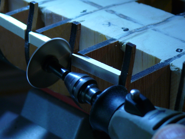
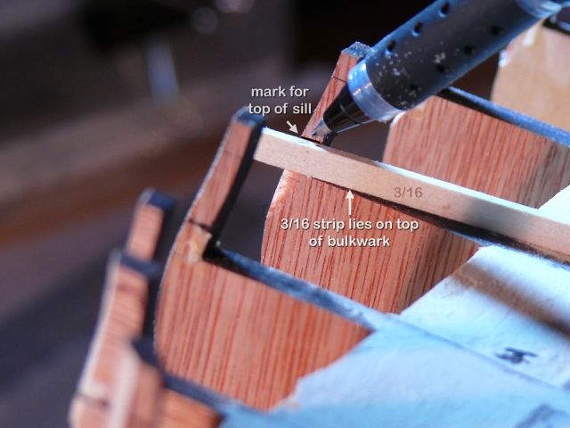
Part 3 - Sill Deconstruction … OK. I went back to other logs and I think I answered my own question. I’m going to go with (3), parallel with the top of the bulkheads. So it’s time to deconstruct. I used PVA glue so far. Rather than trying to un-glue — a messy proposition — I just cut the sills away. Not much finesse required here. Step 1 - dremel with saw attachment: Step 2 - pen sander to remove leftover: (I’m warming up to this pen sander!) Step 3) Re-mark the bulkheads for the top of the sills. I used a 3/16 wide strip as guide to make sure the distance from the top of the sills to the top of the bulkheads ends up 3/16. This was the main reason for the deconstruction. Finally, I bent the planks that will be used for the temporary battens (unlike the first time around). I soaked the battens for 10 minutes, then secured them to the hull for overnight drying. The first time around the sills took an hour and a half per side. So I'll be back in three hours build time.
-
Jesse, I'm a new member also building the Syren. Before starting I studied many logs including yours. I'd like you to know I find your close up pictures among the most useful for answering questions. Thanks for sharing.
- 1,306 replies
-
- 7
-
-
- syren
- model shipways
- (and 1 more)
-
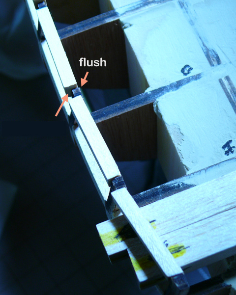
Sal, thanks again. Good to know you are watching! I already modified the post to alert unsuspecting viewers. Although we are allowed a number of mistakes with a ship with this level of details (only the builder sees them), there is a limit. This is a reminder of the importance of reading ahead in the manual. Chapter 7 (p.28) says: "Use a 3/16” x 1/16” thick strip as your first bulwark plank. This plank should fit nicely since you should have 3/16” of space from the top of the bulkheads to the top of the gun port sills." I think it's very important to maintain the 3/16 space from the top of the bulkheads to the top of the sills because it affects all gun ports. Unfortunately in my case it is not maintained for some bulkheads. (Yes, the sills are already glued). Before continuing, can someone clarify this line in the manual (p.11) : "The top of the gun port sills should be perfectly flat. Do not slope them inboard or outboard"? (The top of the gun port sills is also the bottom of the gun ports). Does this mean the top of the sills should be: 1) perpendicular to the bulkhead? 2) parallel to the ground? 3) parallel to the top of the bulkhead? Any help on this will be greatly appreciated. I chose (2) but I think that was wrong, in which case I would start all over again as opposed to try to fix what I have. More fun.
-
Everybody, Thanks. I enjoy doing the log (although I may be spending more time on it than on the actual build ) Sal, thanks for the tip. The battens are back in. There is an area of confusion (to me) as to where these battens should be placed. The manual clearly states that the top of the battens correspond to the TOP of the sills. For my battens it is the BOTTOM of the sills that match the top of the battens. As mentioned, the top of my battens aligned pretty closely to the third mark on the bulkheads, which the manual says is the top of the whales. So who's on first?
-
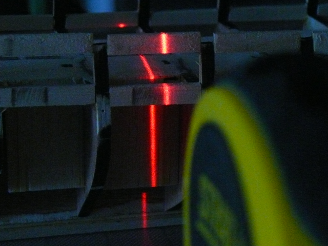
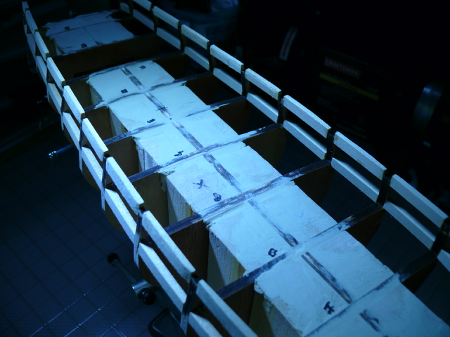
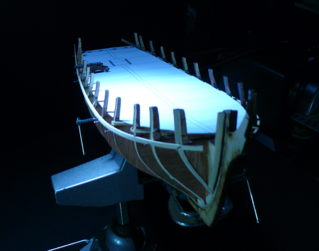
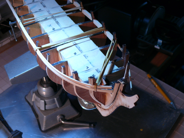
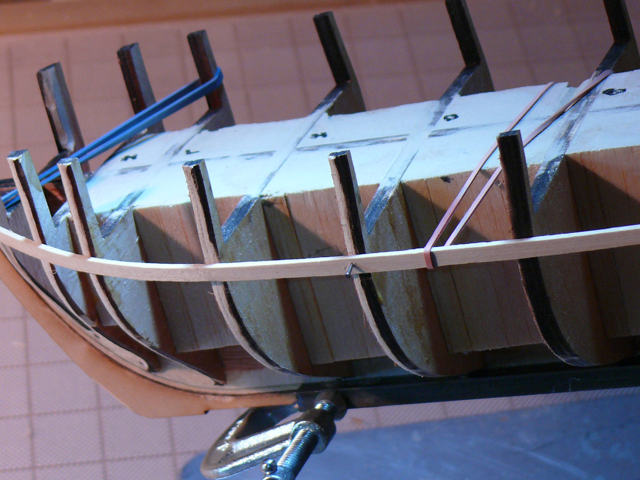
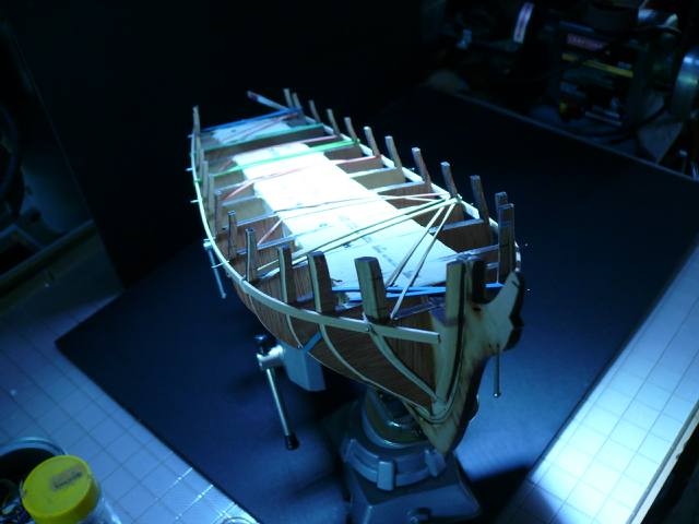
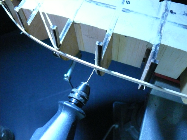
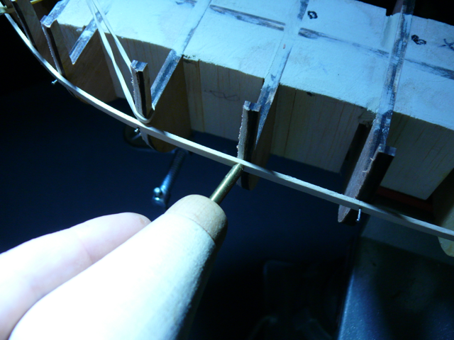
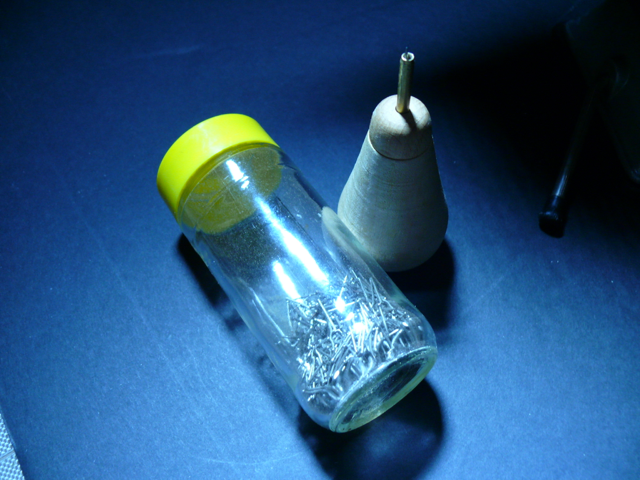
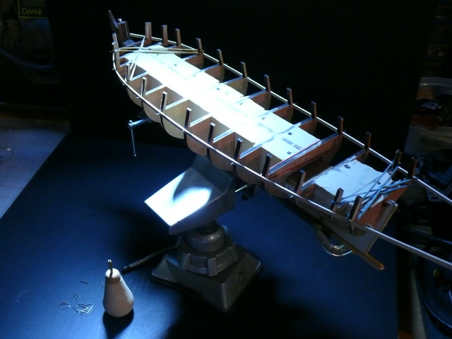
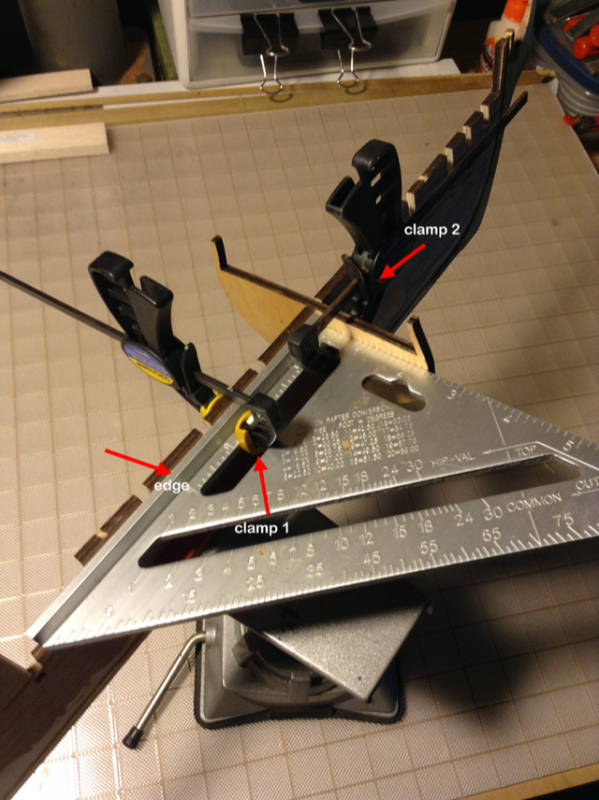
Starting chapter 3 The Temporary Batten I looked and looked and couldn’t find details in other logs on how, precisely, to attach the temporary battens to the BF. I wanted to be able to adjust the alignment to produce a smooth curve. And what to use for battens to begin with? Too narrow, the nails would split them. To wide, they would be inflexible. After some experimentation I cut my own, 5/32 wide strips from a 1/16 basswood plank. (I’m lucky my local hardware store sells basswood in all dimensions. I prefer not to use the kit’s wood for temporary jobs). And I re-discovered the value of rubber bands. I did not pre bend the battens. The rubber bands would keep them pressed against the bulkhead. But I did use very small nails to attach the battens to the bow (BH P), the stern (BH 26) and a couple other location along the hull. At these locations I aligned the battens with the bottom reference mark of the corresponding bulkhead. That was important. (Important ... but not quite right! The battens should have been aligned with the second (from top) not the third reference mark on the bulkheads. The second reference mark corresponds to the bottom of the gun port openings, which is also the top of the sills. _SalD_ pointed this to me after this post, but he also indicated that aligning the temp battens to the thirds reference line might still work. It does.) Now I could wiggle the battens to produce a smooth curve. Here’s a picture of the first batten at this stage: Yes. I did insert rubber bands along the battens before nailing the battens to the bow and stern. Here is a picture of the two battens with mostly rubber bands holding them in place. Now came the time to use more nails to keep the battens in place. After that the rubber bands could be cut. First I used a #60 drill bit to make a hole in both the batten and the bulkhead. (I always pre-drill before nailing). Then I pushed a nail using my nail pusher tool. (One of those “just-in-case” purchases to the chagrin of the admiral). Here is a better view of the tool. Actually pretty handy. It will make a reappearance when it’ll come time for the tree nails and the deck planking, It is hard to start a hole with the drill at a precise location, this tool makes it easy. The last step was to cut away the rubber bands. Here are two pictures minus the rubber bands: Sadly, the purpose of the battens is only to enable marking the bulkhead for positioning the sills. Which I did, then removed the battens. Next: the sills. Thanks for reading.
-
captgino, thanks. Thanks for the thumbs up. They help. _SalD_, when I'm looking for answers, your log is the first one I check. Chuck, you're the boss of bosses!
-
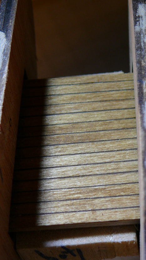
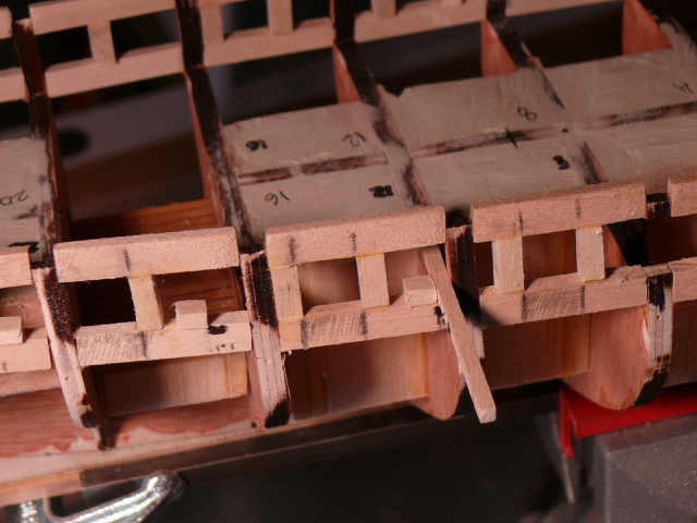
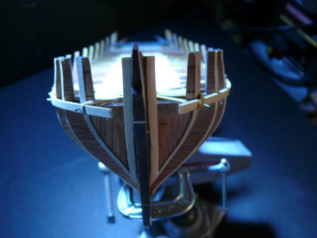
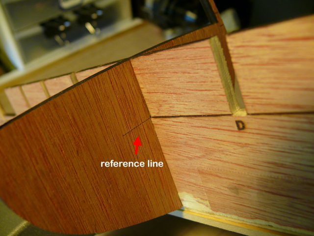
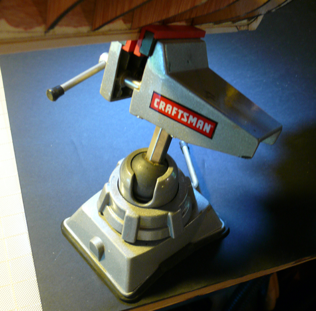
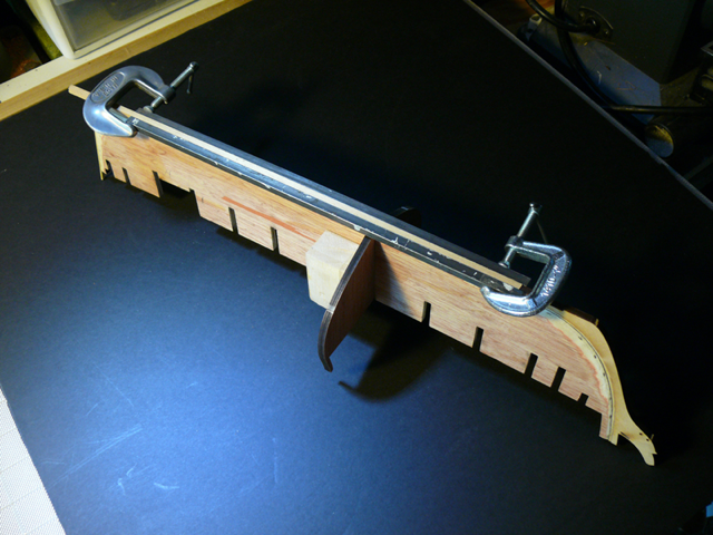
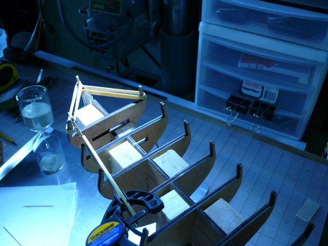
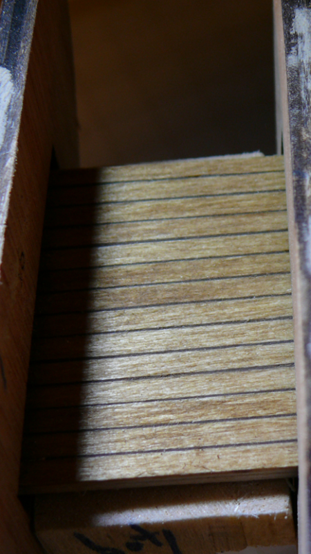
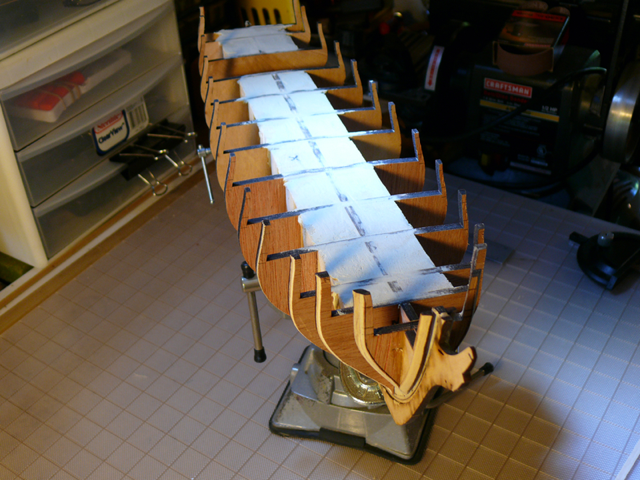
Chapter 2 Fitting the bulkheads to the BF I made sure the reference lines in the bulkhead and BF were aligned. Then dry fitted all bulkheads This suction vise secures the hull and positions it in any direction. Most of the time it’s not necessary to use the suction base. When fitting each bulkhead to the BF, I concentrated on their being perpendicular to the BF. I used a drafting square with an edge that can lie flat against the BF. I chose to glue the bulkheads to the filling blocks and NOT to their respective slots in the BF. One side of the filling block is glued to the BF and the other to the bulkhead. This keeps the bulkheads firmly in place. After the first bulkhead is glued it looks like this. Notice the filling block does not go all the way to the next bulkhead. This is intentional. The gaps will be filled later with wood fill. I also decided to alternate the filling blocks to opposite sides of the BF as I went along. This to have room for the clamps. Again, my main concern at this point is to keep the bulkheads perpendicular to the BF. Still concerned about the curvature of the BF, I secured the keel with two steel rods I found in the garage (who knows where they come from!). I plan to keep the rods in place as long as posible. This is in lieu of building a base for the keel as the manual suggests. More fillers are in place. Notice the hourglass; it is a 45 minutes hourglass. After gluing a filler block (or anything with PVA) it’s a simple visual indicator to know when to proceed. Bulkhead P and the two laser cut bow fillers were assembled separately in order to facilitate beveling. Once the bevel was done the assembly was glued to the BF. Next, the platform between bulkhead 16 and 20 was completed. The ‘simulated’ caulking between platform planks resulted from darker wood filler inserted into small separations between planks. The planks are then scraped. The problem is that it looks too neat, so I may not use this method for the deck. I ignored the tree nails at this point. Finally the overall beveling of the hull was done with plain old elbow grease. Here is a photo of the completed filler blocks with gaps filled with wood filler. This completes chapter 2. Thanks for reading. Total hours to this point: about 18.

-
Ryland, EL_L, thanks for the welcome .../hervie
-
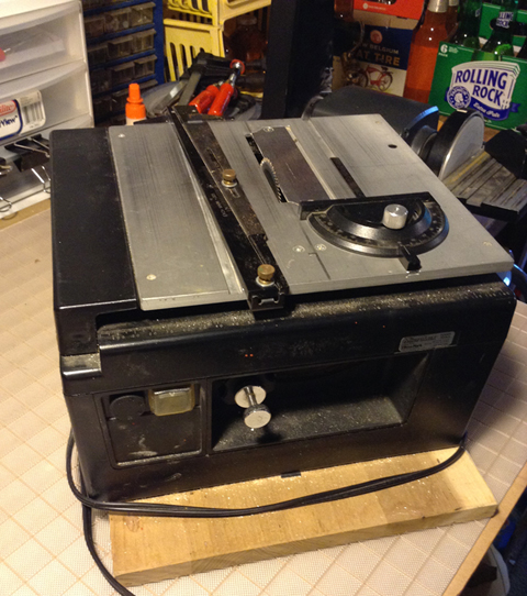
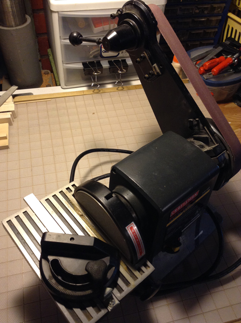
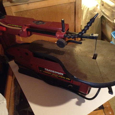
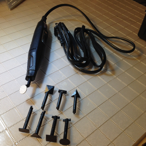
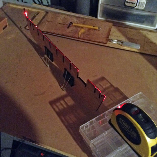
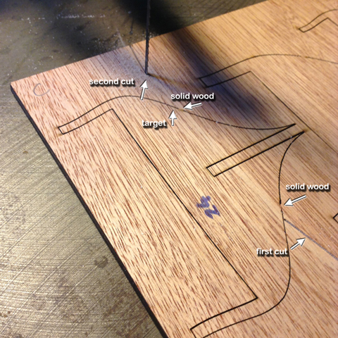
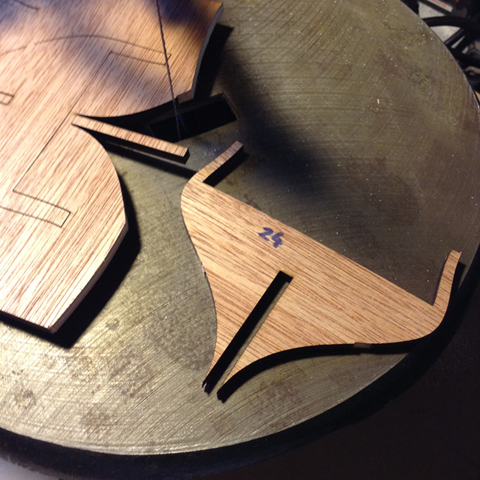
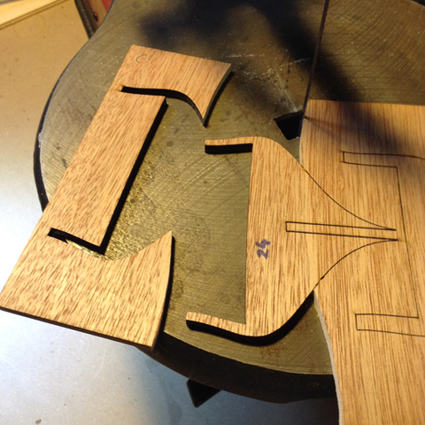
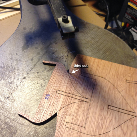
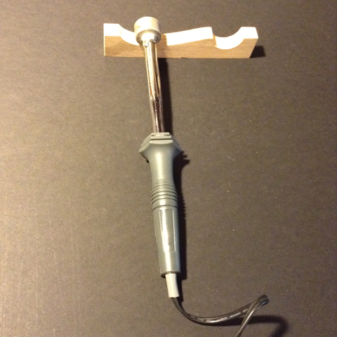
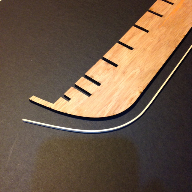
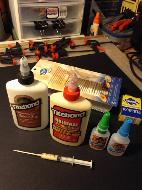
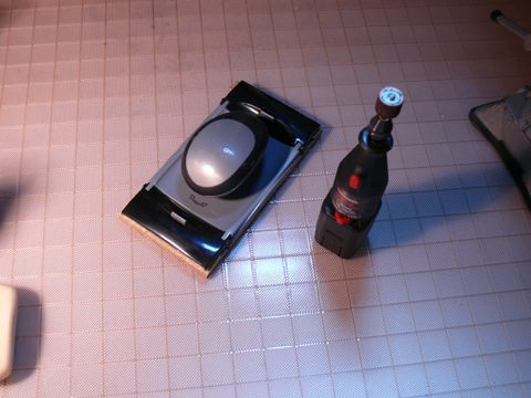
Hello everybody. I’m Hervie. Glad to join this company of model builders. Why the Syren? Because of the excellent manual and because of the build logs found in this forum. I studied them all. Thank you members for your efforts in documenting your builds. For those of you unfamiliar with Chuck Passaro's excellent manual, here is a link to it: http://www.modelexpo-online.com/product.asp?ITEMNO=MS2260 Couple things about myself: I’m a retired software engineer here in Silicon Valley. In addition to model building I write apps for the Apple App Store. Since retirement I’ve built four model ships, one after the other, and all of the same ship: the Bluenose from Artesania Latina. (I know this is unusual, but like Steve Jobs said: “The journey is the reward”). I gave them away as presents. That was eight years ago, and since then nothing on the modeling front. Now I resurrected all my tools and am about to embark on the Syrus. I’m very excited about it. About this log —————— I'll skip the unboxing of the kit. Others have done a good job at displaying the contents. I'll concentrate in describing the hurdles whose solutions I did not find in other logs. Possibly because those hurdles may be trivial for others to solve. Any advise will be greatly appreciated. I am creating this log first as a document on my Mac, then transferring it to the forum log. My tools ———— Aside from the regular clamps, cutters, dremels, measuring tools etc, I’ll be using four power tools. 1) a MicroLux Mini Tilt Arbor Table Saw from MicroMark. I use it with a vernier adjustable rip fence for very accurate rip cuts. (also available from MicroMax) 2) A single speed belt/disk sander. Big and clunky, but very useful, particularly the disk sander. 3 ) A scroll saw. Of the three the least useful for model building, but good to have when need it. 4) A pen sander from MicroMark. Don’t have any experience with this tool but others said is pretty useful. The kit ——— The kit arrived in good shape, promptly, and apparently complete. I was not expecting some parts to be so small, like the rigging blocks whose size is not apparent in the photos. Rigging is going to be a challenge. After reading about the misadventures of others with warped Bulkhead Formers (BF) and fragile bulkheads, I checked my BF and was relieved to find it very robust, with clear and precise laser cuts. However the relief was suspended when I discovered it to be slightly warped. I used a laser gadget to check for straightness since my glasses show everything curved. Chapter 2 of the manual mentions that any warp in the BF may disappear after gluing the filler blocks. Let’s hope. Anxious to check the bulkheads, I run into the first hurdle. How to separate them from The BF? The laser cuts are so fine that no blade can be inserted in them. So I came out with this solution: 1) Only two small solid wood areas keep each bulkhead attached to the BF. So for each bulkhead, with the scroll saw (any saw would do) I made two cuts on either side a the bulkhead terminating just above the respective solid areas: This resulted in the top part of the bulkhead to separate from the BF. 2) Following the contour of the bulkhead, I cut the solid wood area attaching the bulkhead to the BF: And voila! Removing all the bulkheads, stern post and rudder took about 1/2 hour. Not a single piece was damaged. The rabbet ————— I glued the rabbet to the BF in spite of the BF being curved. I bended the rabbet with the method described in the manual, but also with the assist of the electric plank bender tool. I am not known for my patience … bended rabbet strip: gluing the rabbet: For glue I used the original Tilebond. I was surprised about how quickly it sets, less than a minute. Centering the rabbet on the BF edge had to be done fast.. These are the glues I am using: Carving the BF from the bearding line to the edge of the rabbet. Since I’m not good at carving, I tried a portable Dremel with a drum sander at low speed. That worked well although the photo looks messy. Another view of the rabbet . The stem post was trimmed with the disk sander. This concludes chapter 1. Thanks for reading.