KurtH
-
Posts
449 -
Joined
-
Last visited
Content Type
Profiles
Forums
Gallery
Events
Everything posted by KurtH
-
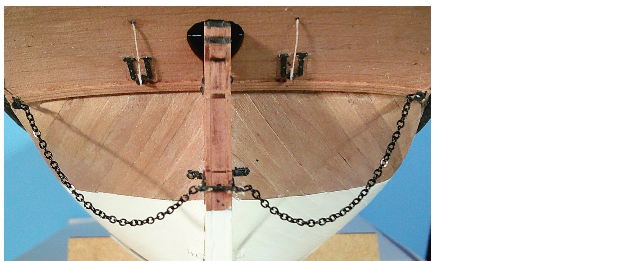
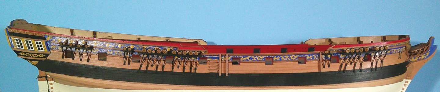
It turns out that I did have the time to install the rudder chains: And what beautifully manufactured and finished chains they are too! So here is the state of play as of today: I expect to resume work in mid January.

-
I forgot to mention that I have glued the rudder back on, this time with Devcon 2-ton epoxy. I will be really disappointed if it comes loose again.
-
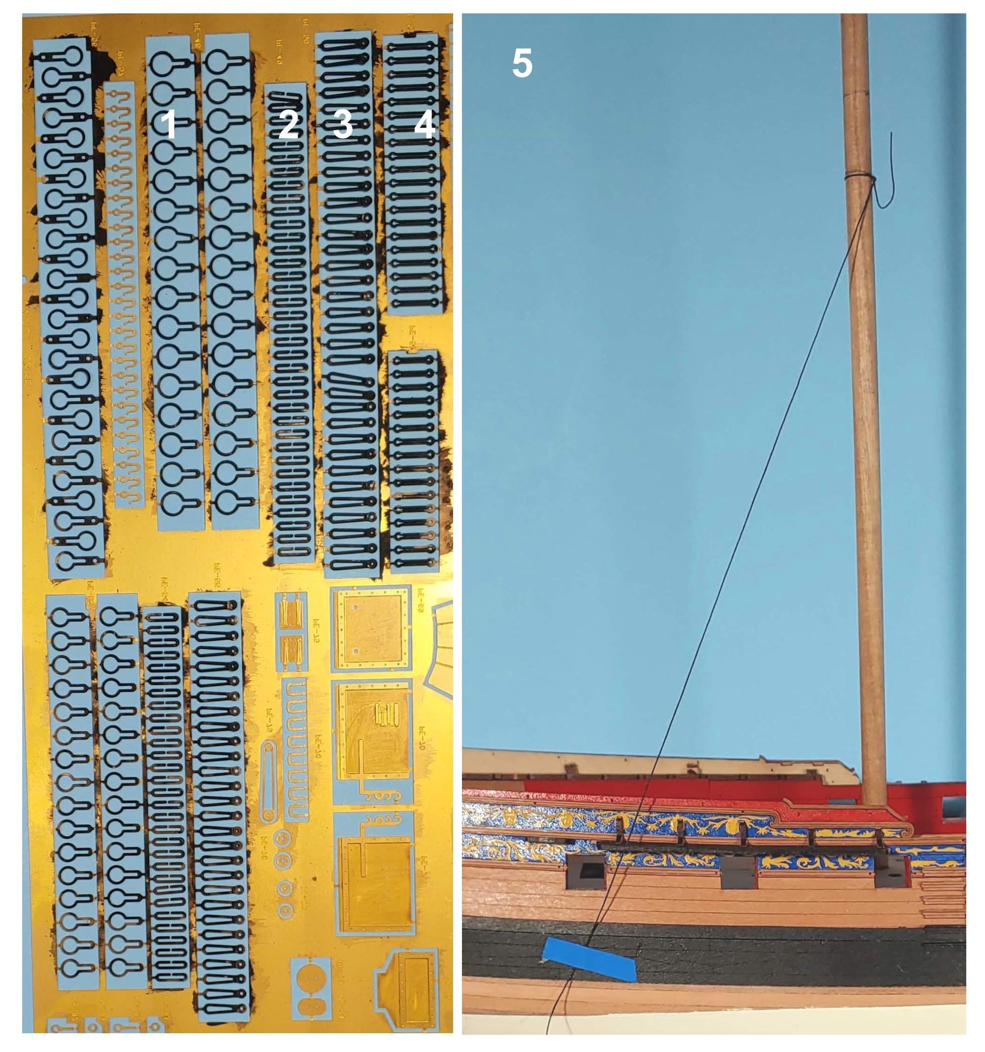
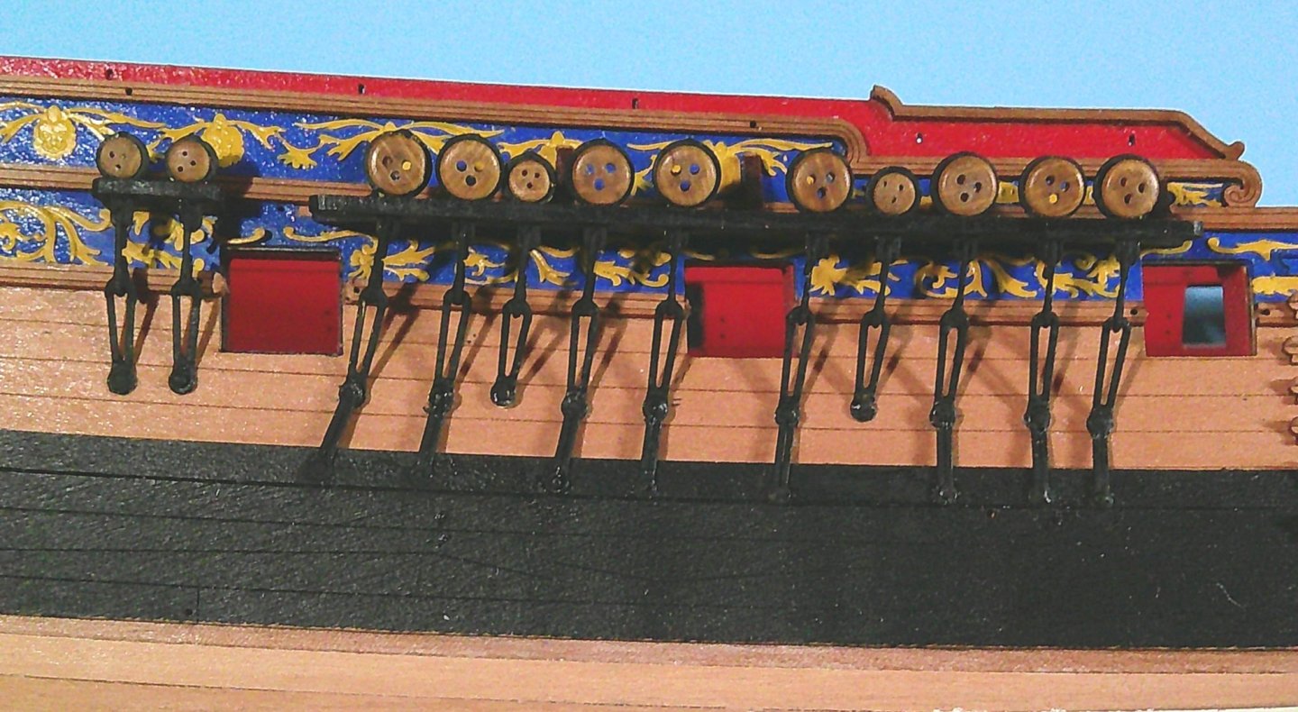
Work on the chains has been completed except for the mizzen backstays. It looks like these will stick up, begging to be broken off or bent, so I will wait until much later to install them. The components of the chains are all on the PE sprue, including some extras of each: 1. Strops 2. Mid Links 3. Toe Links 4. Backing Links (AKA Preventer Links) 5. The method I used to determine the angles of the link assemblies. Here is a photo of the starboard main chains: And here is a shot of the finished chains: Next are the rudder chains. Let's see if I have the time to do that before I have to put this project aside to do video and audio work.

-
Thanks Ron!
-
Hinges and ropes installed for the bridle ports and airing and small items loading ports. The afore mentioned PE letter "P" arrived from across the pond (Thank you Chris!) enabling me to complete the name on the upper counter: Now on to the chains.

-
Thank you so much Rick!
-
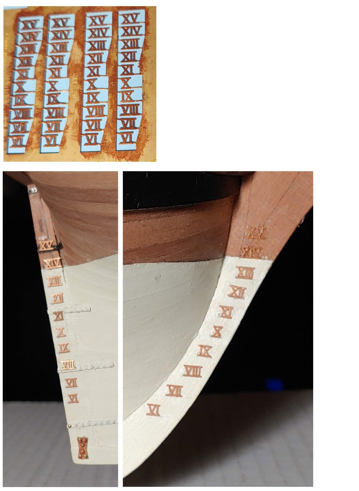
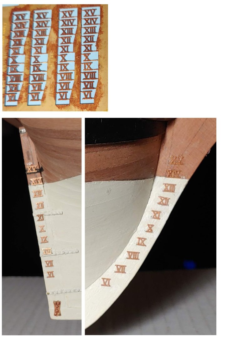
The next step is to prime, paint, remove from the sprue, and glue on the depth numerals: The next step is to install the hinges and eye bolts on the chase port and stern ports and do the rigging.
-
Immaculate work as always!!
-
Thanks so much Ron!
-
Time to glue on the PE decorations to form the frieze. Here is a sampling of the PE filigree: The numbers you see on the sprue correspond with those on the detailed 1/64 scale drawings provided, assuring accurate placement of these elements on the hull. And here they are all glued into place using Vallejo acrylic matte varnish with occasional touches of CA: I have seen several different versions of this frieze in other builds, and I applaud the skill needed to pull them off, but I am content with the bas relief design, electing only to change the color from gold to yellow ochre.


-
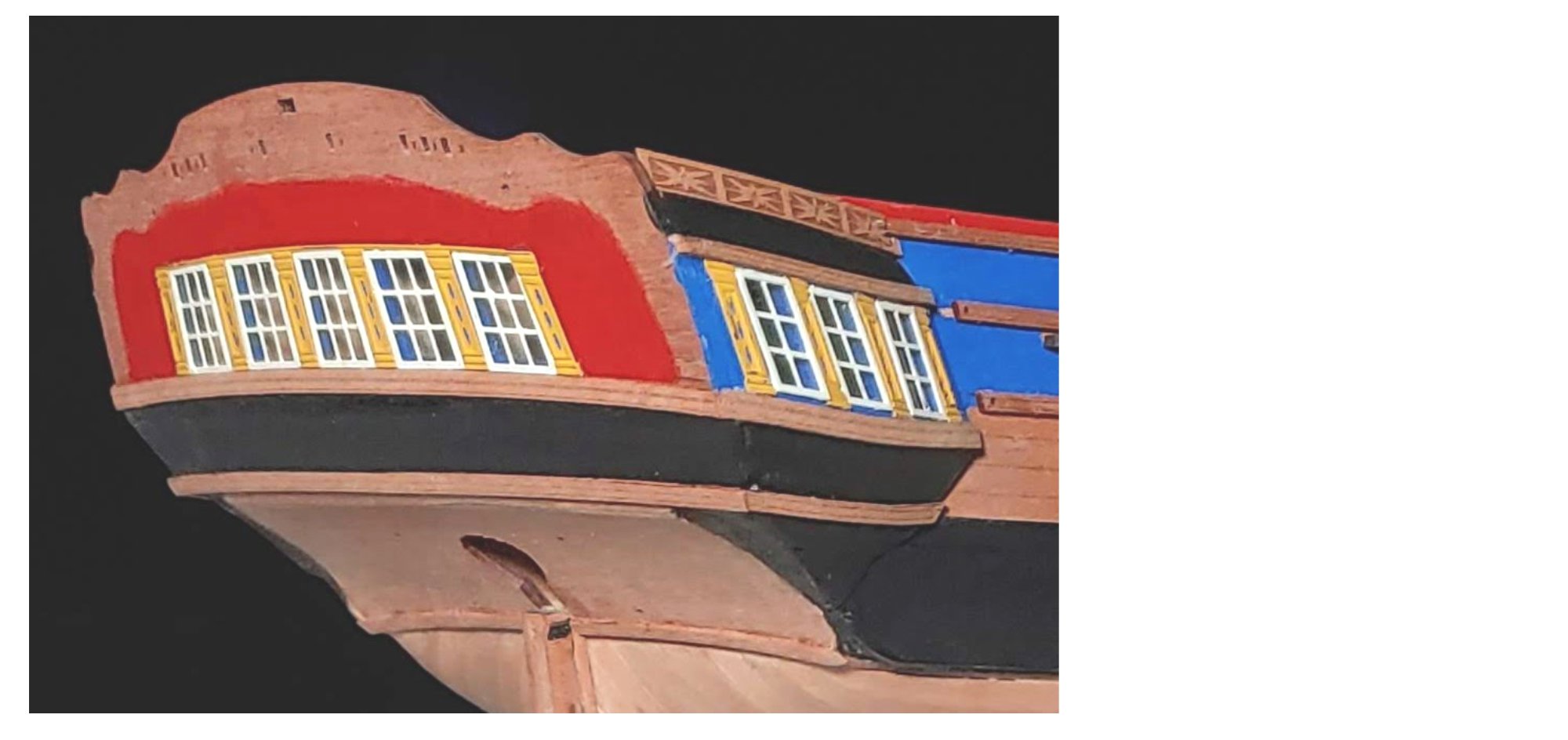
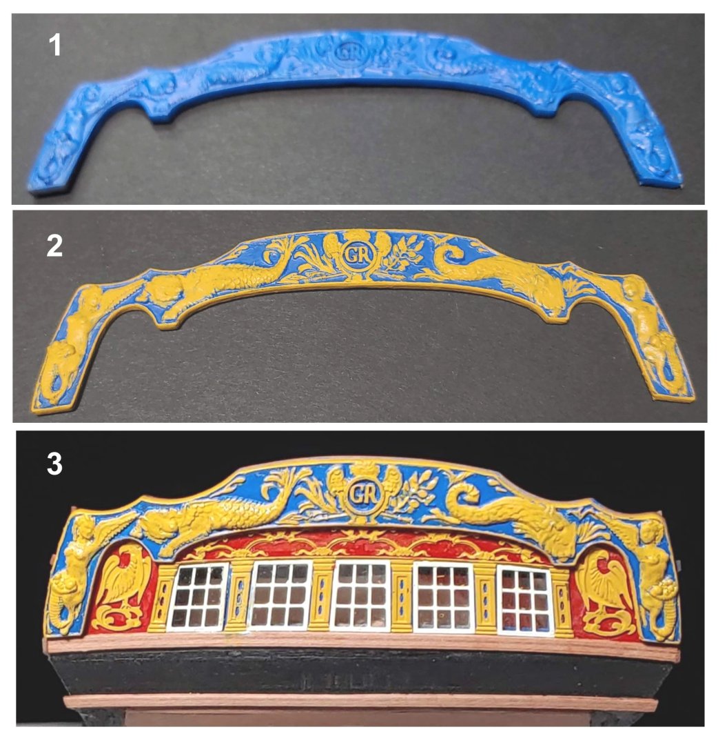
Work is proceeding on the stern: 1. Background painting done. 2. Acetate window panes and frames installed. The same issues I described in my reply to @Ronald-V question are the same here. 3. PE pilasters glued in place using CA. Rails installed. My rendition of the stern is not without its flaws, but at least I managed to have the quarter gallery rails and the transom rails meet neatly at the corners. Next: 1. The superb cast resin taffrail, primed and painted Vallejo Royal Blue. 2. My best effort to paint the detail thereon with yellow ochre. Touchup was done on the pilasters after the photo was taken. Why not before? Well, that's a long story. I began work on the upper counter, but the letter "P" in the name disappeared seemingly right out of my hands. I contacted Chris expecting to buy a new PE sheet, but it turns out that he had some scrap parts of that sheet at hand, and was willing to send me a new "P", no charge. I can add my gratitude to the many compliments I have read concerning Chris's customer support. I will post the results of my efforts at decorating the upper counter when I have finished it. Meanwhile, the next step is the assembly and installation of the gangway steps: 1. These parts sure beat having to make them from scratch 2. Having looked at photos of the gangway steps of HMS Victory, I decided to round the steps. 3. After having exposed the bare wood where the steps will go with the point of a file, I glued the steps in position using PVA. The laser inscribed lines were a big help, especially in view of the fact the steps do not line up with the planks, but with the water line.


-
Thank you Ron. The paint impeded the reaming out of those openings to accommodate the acetate window panes which were larger than I anticipated. After having made a mess of the forward opening on the port side, I ended up filing down the acetate panes to fit. As I could not do the same with the frames which were the same size as the panes, I installed the panes flush with the gallery pattern and then added the frames on top, leaving them proud of the surface of the gallery. This defect became a lot less noticeable once the plasters were installed fortunately.
-
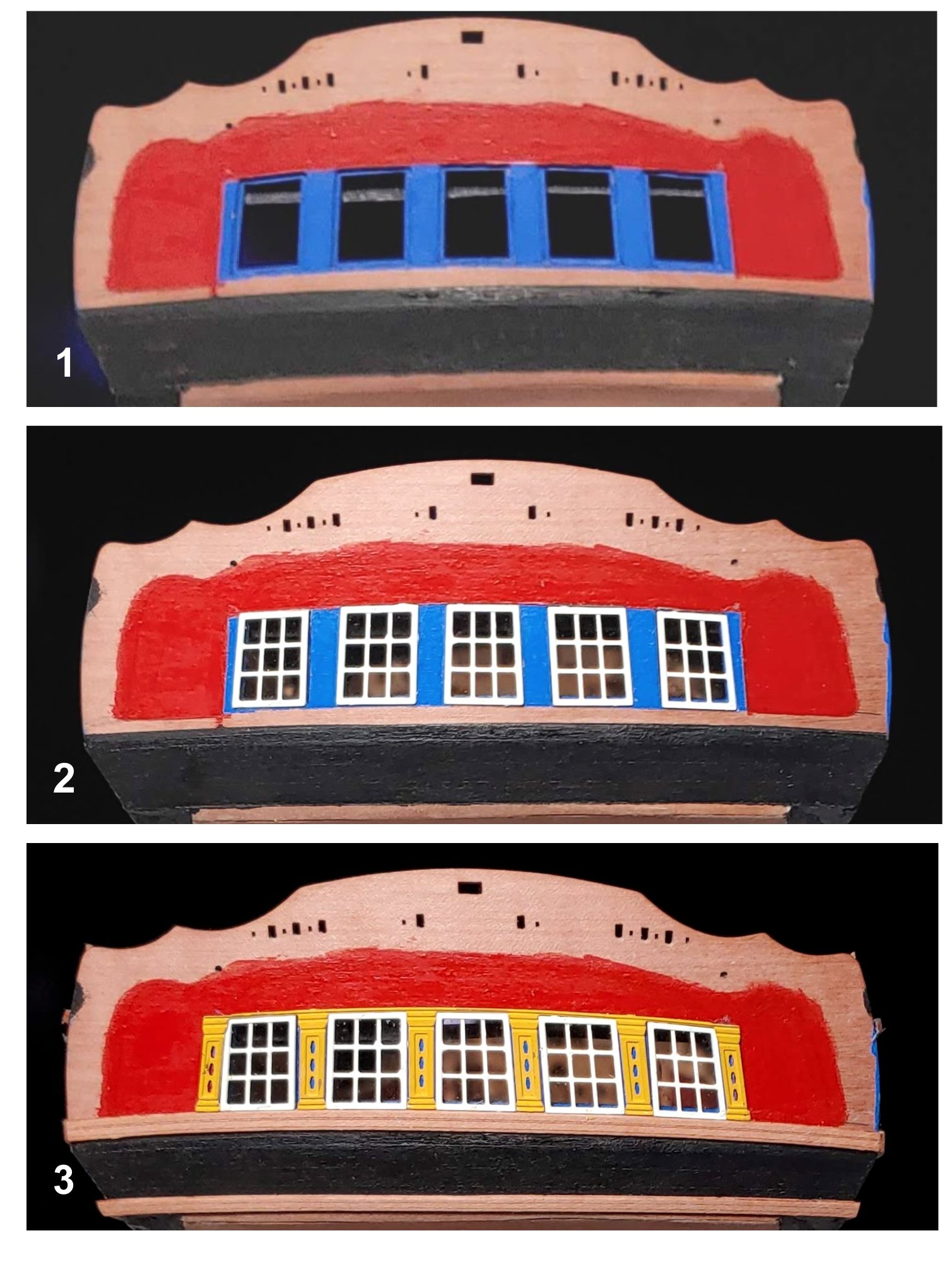
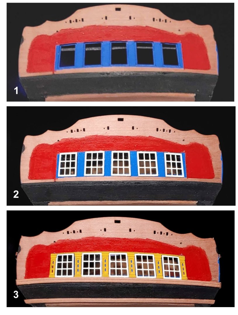
Work is proceeding on the stern. I have not quite finished the transom yet, but I did finish the quarter galleries, so I thought I would post that work now. Here is a shot of some of the PE items which have been primed and painted: As you can see, I elected to paint the decorations yellow ochre rather than gold. I started with Vallejo Yellow Ochre. I thought it was too dark, so I added two drops of Vallejo Ivory, then a squirt of Vallejo Light Yellow which gave me the tone I wanted. I looks very dark here, but the following photos give a better idea of the actual color: 1. I painted the window insert spaces blue. Big mistake!! It caused me no end of problems when the time came to insert the acetate window panes. 2. Acetate windows and their frames glued in place. I used Vallejo matt varnish for this. 3. Rails PE pilasters, and upper fret work installed. I notice that in other builds, there is quite a variety of color schemes used in the fret work and in the bow head rails and bowhead timber fasciae. I thought about doing that, but ended up deciding to leave well enough alone, discretion being the better part of valor. 4. PE decorations added to the quarter gallery berthing patterns and lower finishing stool. I applied a coat of varnish, installed the decoration, then put another coat of varnish over that. The instructions suggest doing that with floor polish, but I found that this method also works. It turned out that there was not enough room for both PE parts on the lower stool, but I am happy with how it looks with just the lower one. 5. Shingles added. One of the PE shingle patterns slipped out of my hand and into the space between spaces, so there are three rows here instead of the four that the instructions call for. I see that several other fine builds also have three rows, so I do not see this as a disaster. There are four rows of shingles on the port side, but as one can only see one gallery at a time, and as I never had any thought of entering my work in a show, I can live with it. You might have noticed that the rudder is absent in these photos. I found it difficult to handle the model while applying decorations without having the rudder come loose, so I removed it. Once all the outer hull details have been completed, I will re-attach it, this time using maximum strength epoxy. I will post my work on the transom when I have finished it.


-
The rake is relative to the water line. According to the BJ instructions, the foremast has a rake of one degrees. The mainmast has a rake of 2 degrees, and the mizzen mast has a rake of 3 degrees.
-
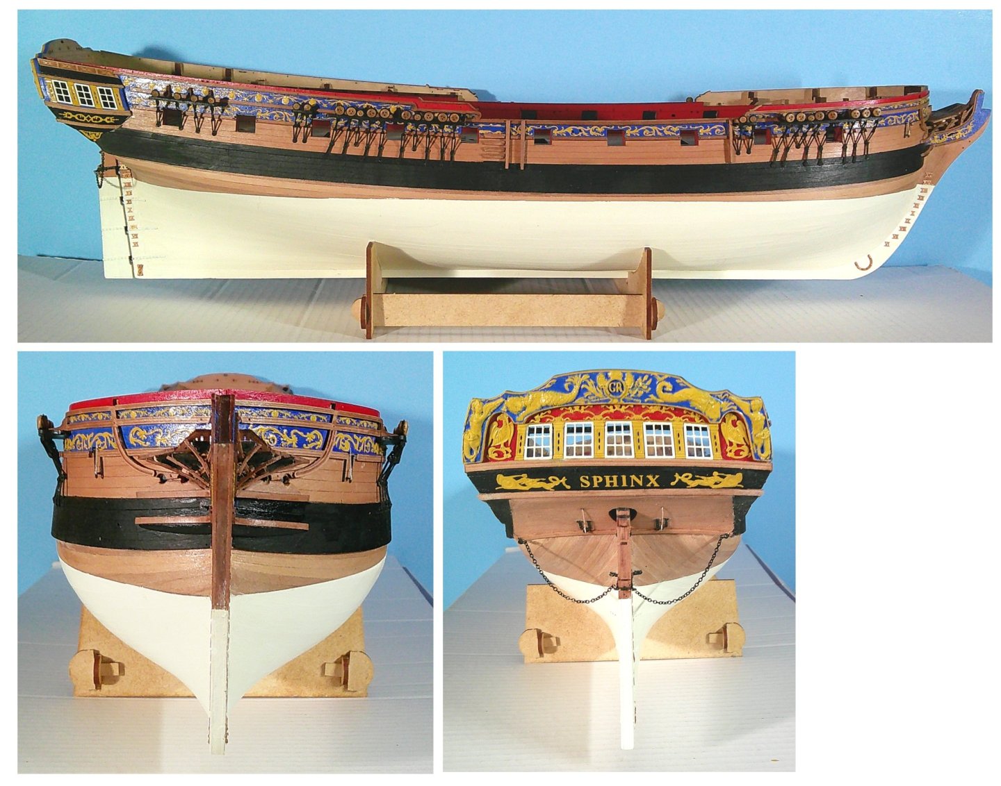
I agree. So do a number of other ship model enthusiasts. Before all is said and done, there may be enough Sphinxes on MSW to form a squadron. By the way, the blue is Vallejo Royal Blue.
-
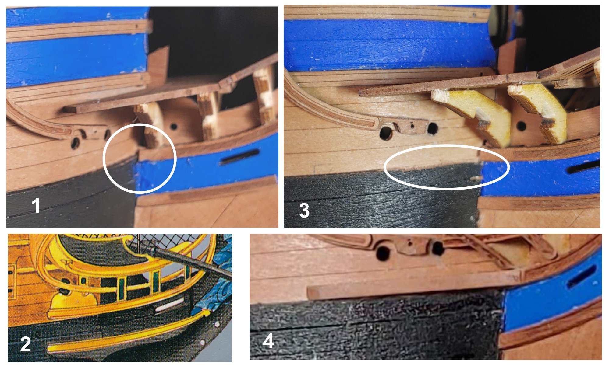
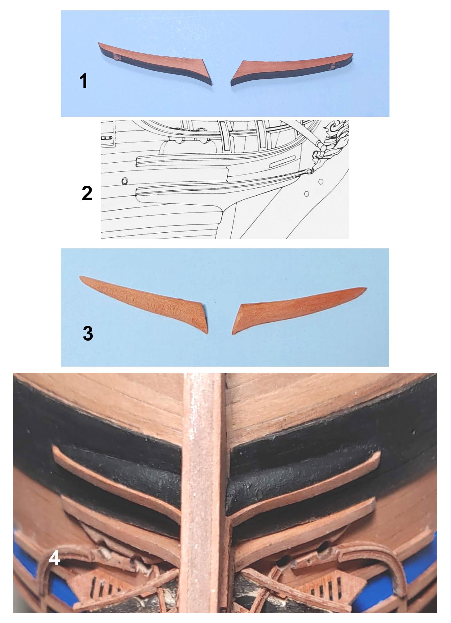
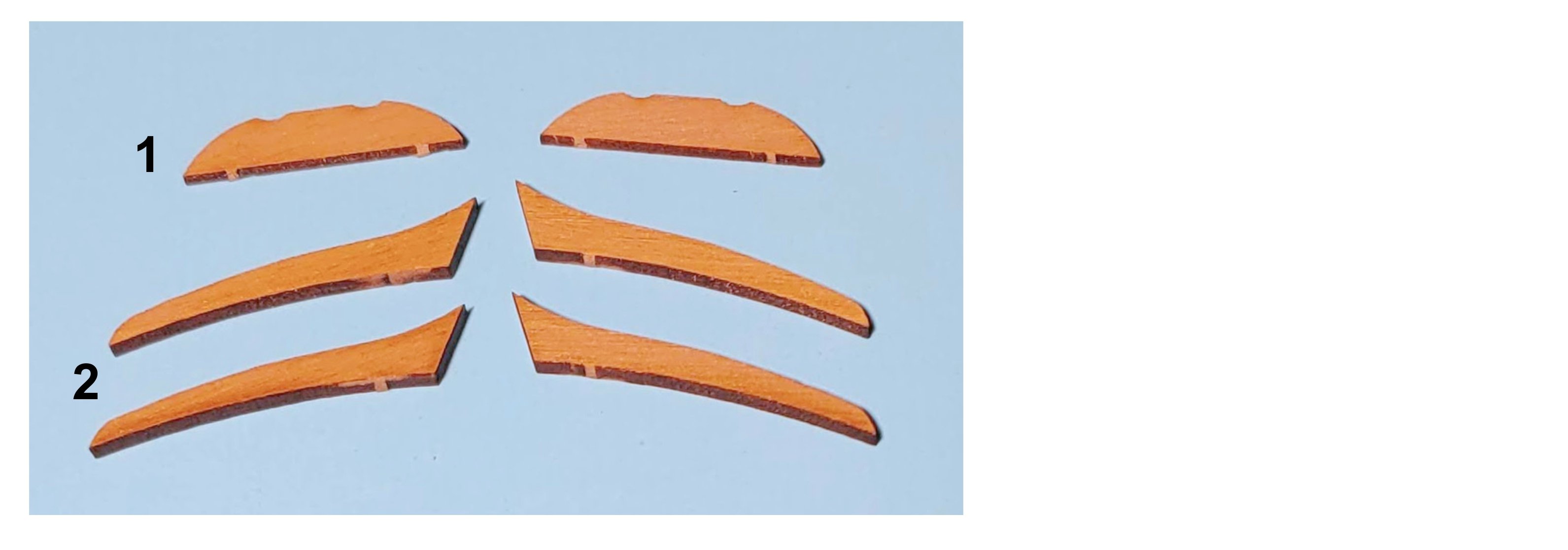
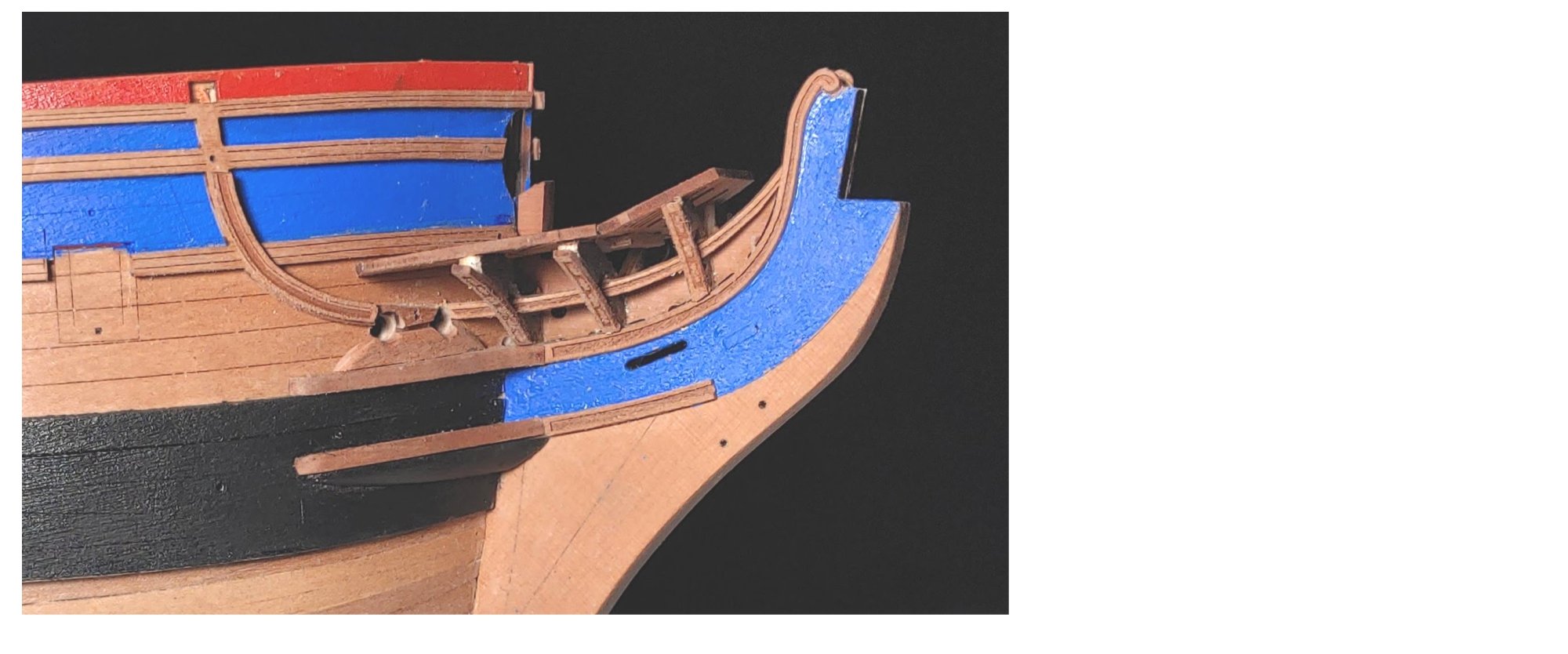
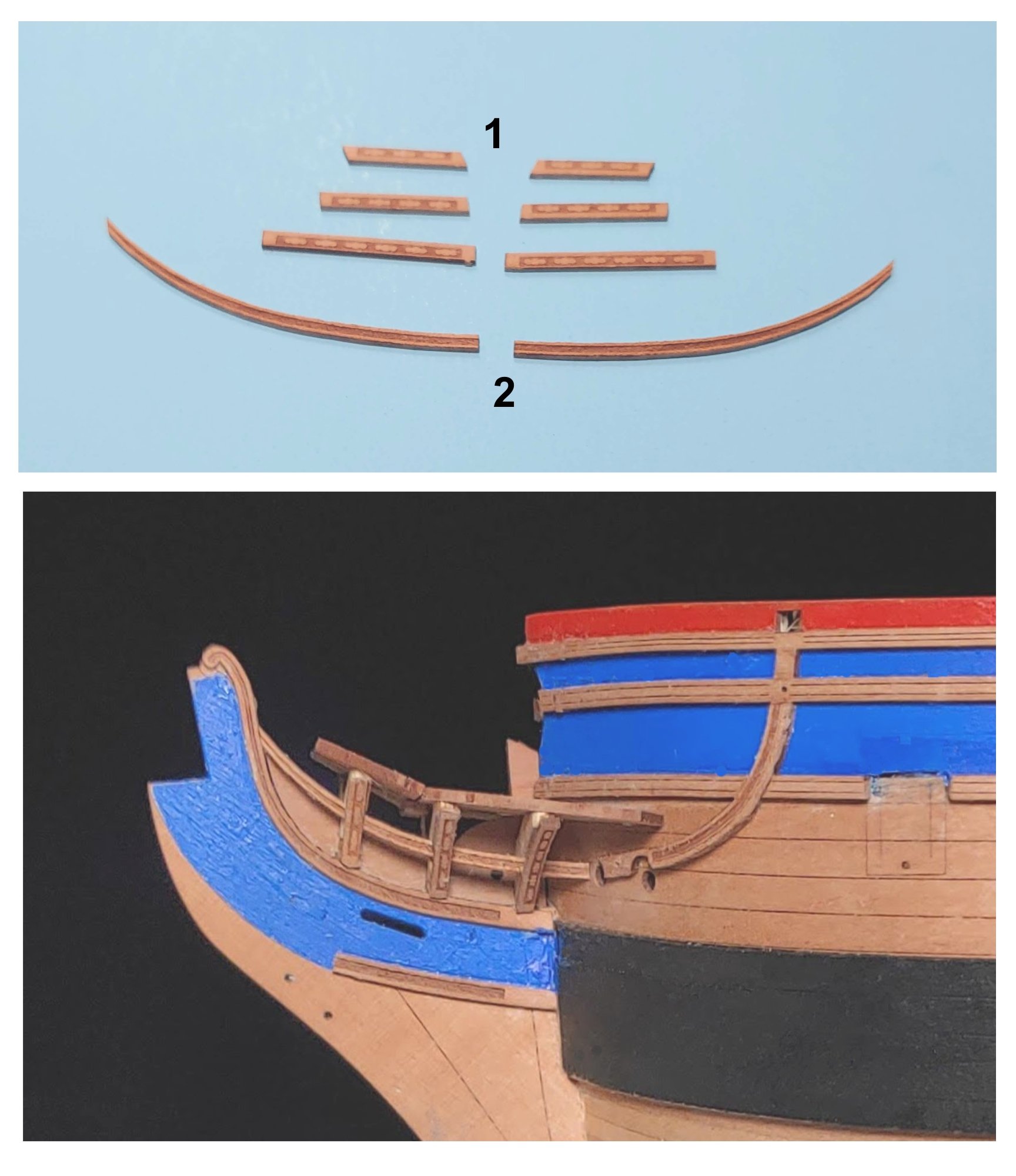
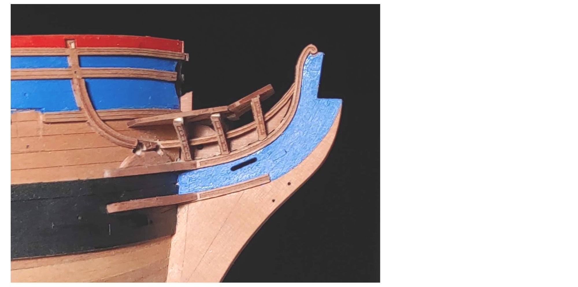
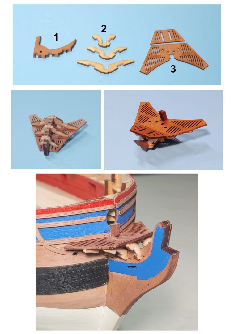
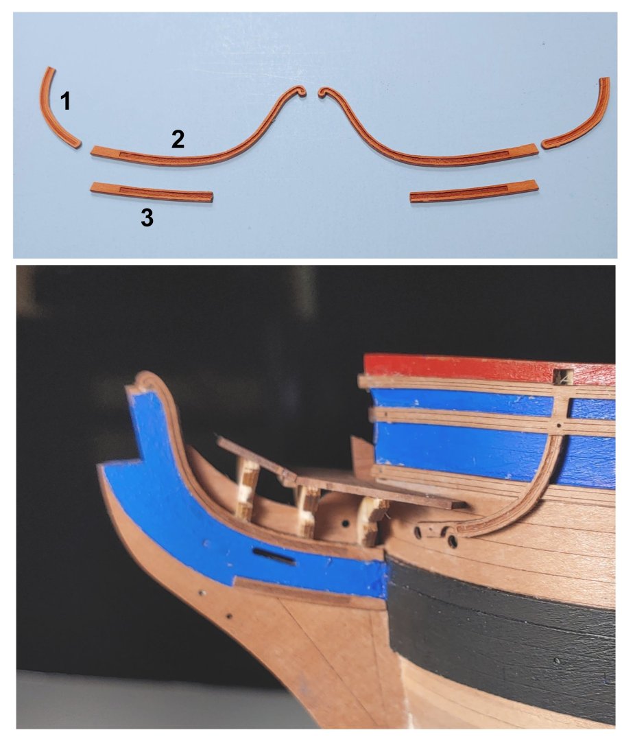
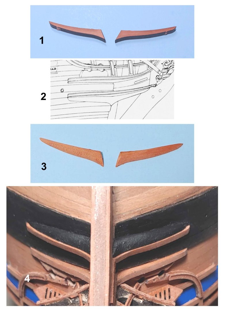
Now for the bowheads. 1. Gammoning knee 2. V brackets (AKA bowhead timbers) It did not occur to me to paint these black. Once I got everything together they stood out like the proverbial sore thumb from all the pear components. I noticed that in step 300 on p. 52, they are black. I saw the same in James H's build. I managed to blacken the forward surfaces of these with a fine felt tip pen as you will see. 3. Bowhead grating. Photos of their assembly are self explanatory. They fit together very well. Next up: 1. Ekeing moulding patterns. There was some temporary confusion as these parts do not match what is shown in the photo (p51, #288), but looking at other builds cleared things up for me. 2. Bow hair brackets: 3. Bow lower rail Next I installed the second rail (2) and the head timber patterns (1). This is not in the prescribed order, and I do not have an explanation of why I did it at that time. I do not necessarily recommend it. On the other hand it did not cause any problems for me either. 1. Facia for the outboard edges of the V brackets. I needed to soak and pre-bend these as they were not flexible 2. Second rail Next step, the bow cheeks (2) and hawse bolsters (1): The next set of photos illustrates a problem I ran into and how I got round it: 1. It seems that I installed the wales 1.5 mm too low resulting in the mismatch identified by the circle. The upper edge of the cheeks should coincide with the upper edge of the black strake which then lines up with the bow hair bracket. 2. I looked at the bowhead illustrated in the Pandora AOTS and saw that the upper cheek sits atop the wale black strake. 3. I trimmed down the wale a bit. 4. I then installed the upper cheek. Now it lines up with the bow hair bracket. The Pandora was a sister ship to Sphinx and nearly identical to her in most respects, so I do not think I am completely off base here. Lastly, the wash cants: 1. The wash cants as provided. 2. Again, I looked at the Pandora AOTS and liked the shape I saw... 3. ...and replicated it as closely as I could. This took some time as you can imagine. 4 They fit nicely under the lower cheeks. This completes the bowheads except for the main rails, seats of ease, and figure head which will be added much later in the build.


-
Thanks so much Ronald! I look forward to seeing what I have no doubt will be an immaculate set of channels.
-
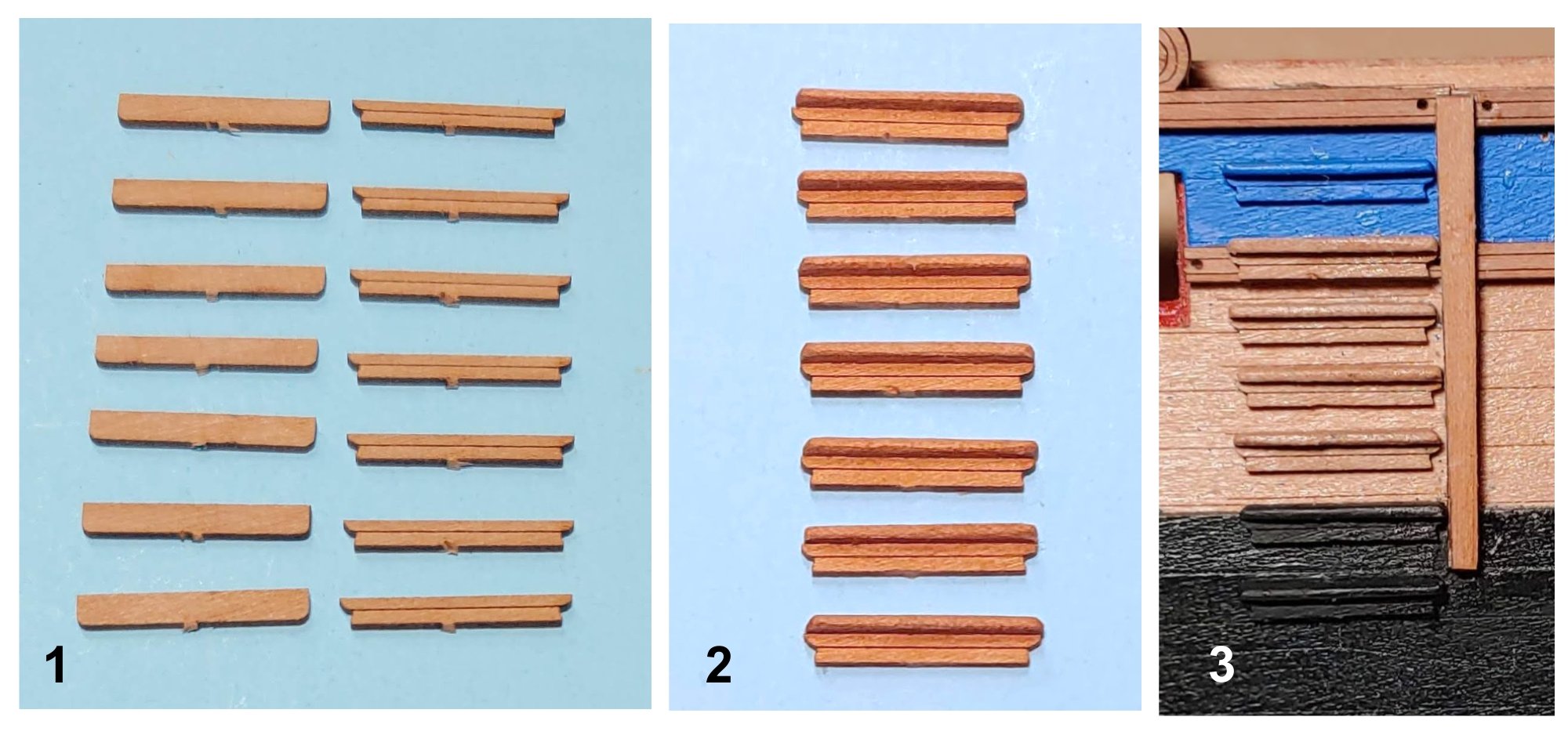
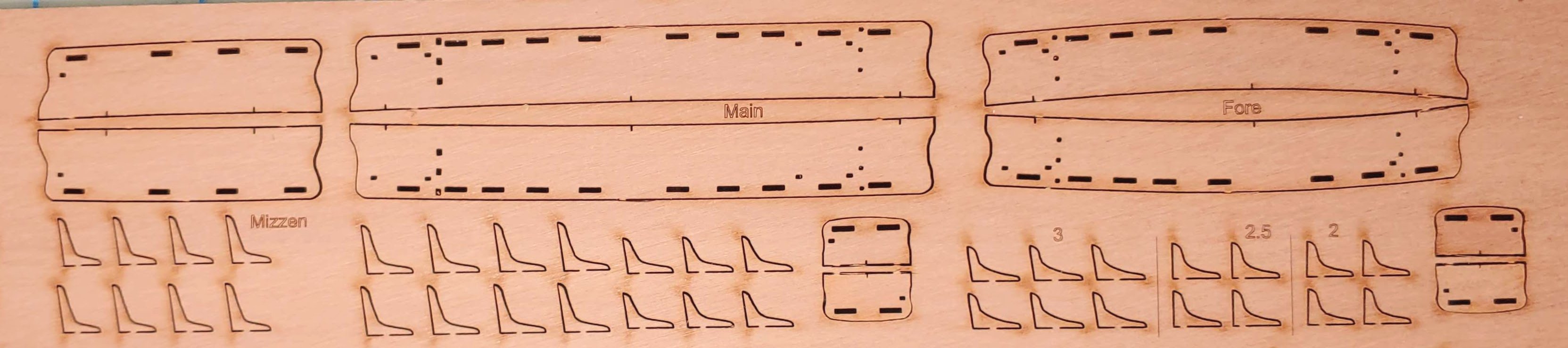
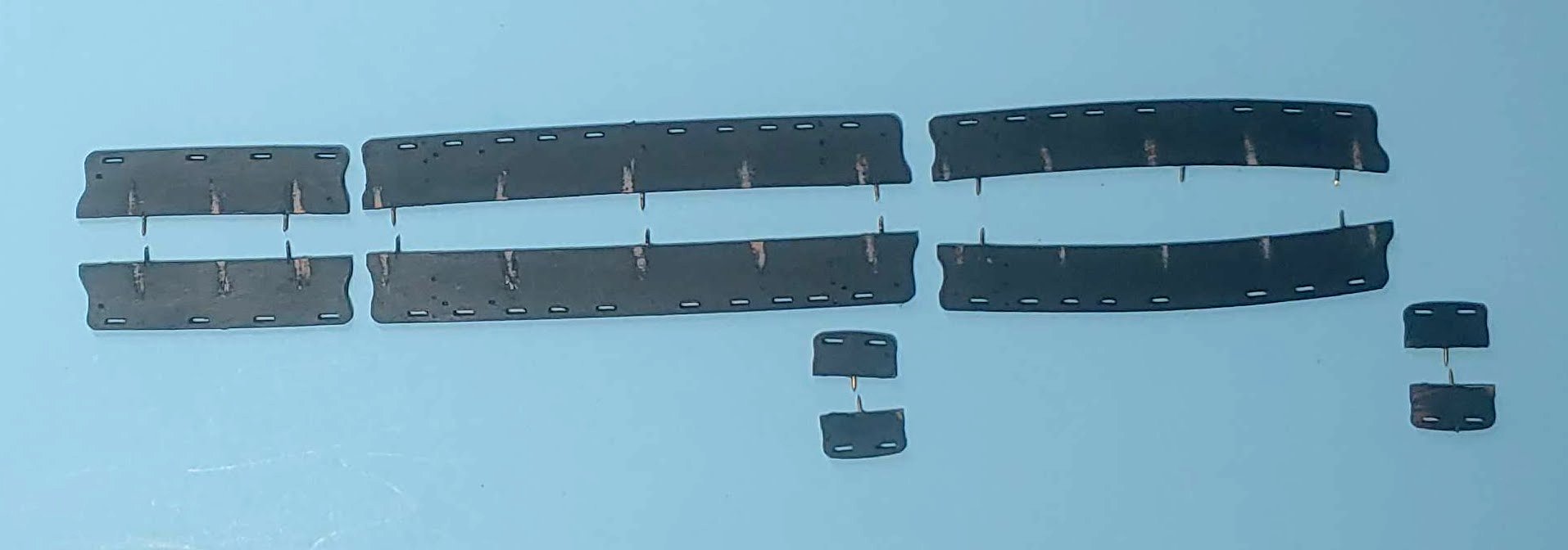
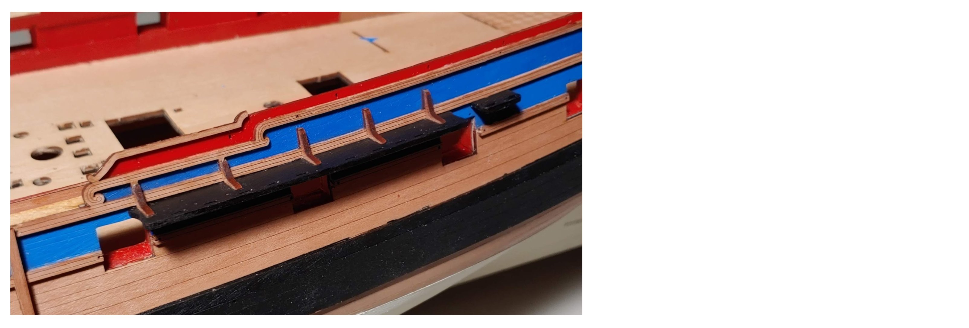
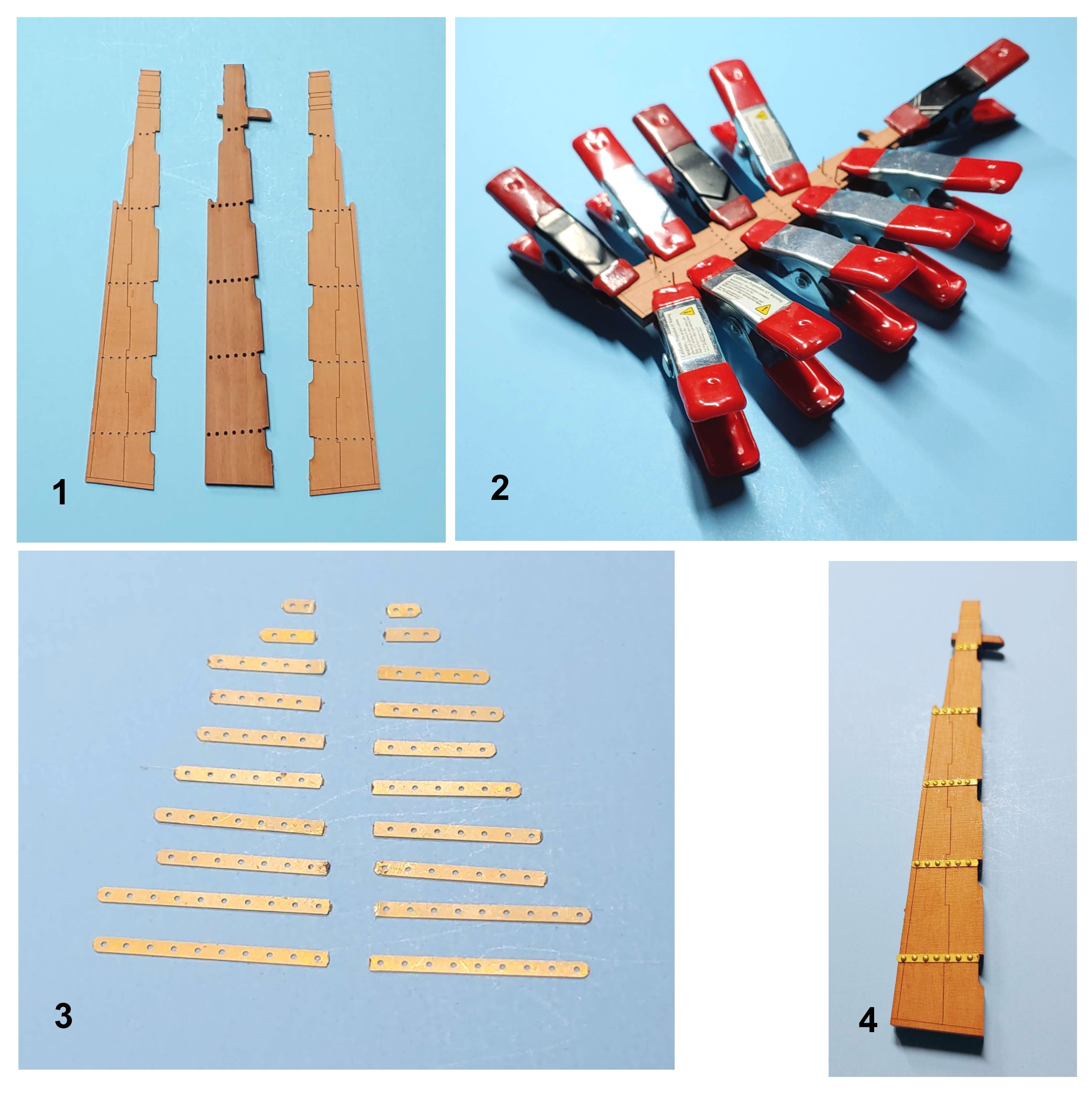
Nest step: preparing and installing the channels. These are the channels and their knees as they appear in the sheet: Here are the channels after having been painted, paint removed at the places where the knees will be located, and the pins installed: Holes are drilled into the channel at the laser cut notches. If you do this by hand as I did, be careful that your bit does not emerge from the upper or lower surface of the channel. The ends of the pins which have been cut off during the installation of the pintle and gudgeon straps are then inserted and glued in so that the points face outward. These in turn go into the holes provided in the planking pattern. It all lines up well insuring precise location of the channels. Here is a view of the port main channel with its knees installed: This is the current state of play:


-
Thanks Ronald! I appreciate the compliment! I use small pliers with serrated jaws to grip the pins. I have lost a few into the space between spaces. For any work which involves inserting pins, I recommend a Pin Insertion Plier (Micromark #85282). I found mine absolutely indispensable.
-
Gudgeon straps installed and painted: As you can see, I did not insert pins where the depth numerals will go. Yeah, I know, the quarter galleries need touchup. That will be done when work on finishing them begins. Next will be installation of the channels. Gluing in the pins will require great precision, as the holes provided are very close the rails. Wish me luck.
-
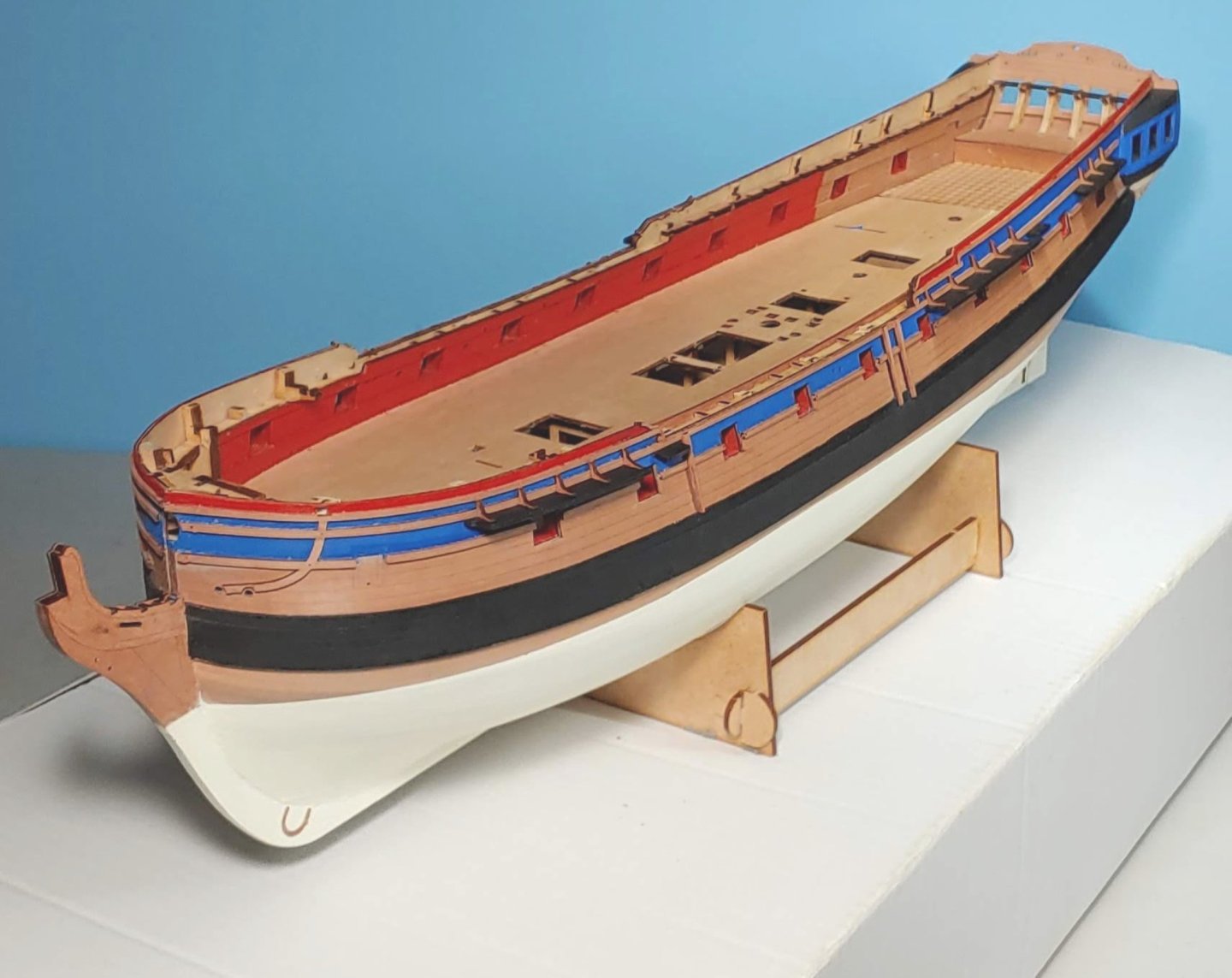
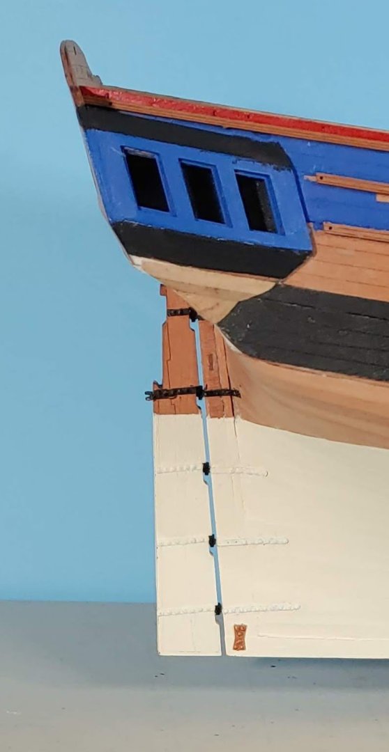
Horse shoe and fish plates installed. Copper paint was applied to the pin heads with the sharp point of a bamboo skewer: Rudder glued in: Installation of the gudgeon straps is proceeding.. Precise alignment of the straps is challenging for me due to their tendency to shift slightly while i am inserting the first two pins. This may take a while.


-
Thanks Ronald. I will watch what you do with great interest. I was thinking of not inserting the pins where the depth numerals will go.
-
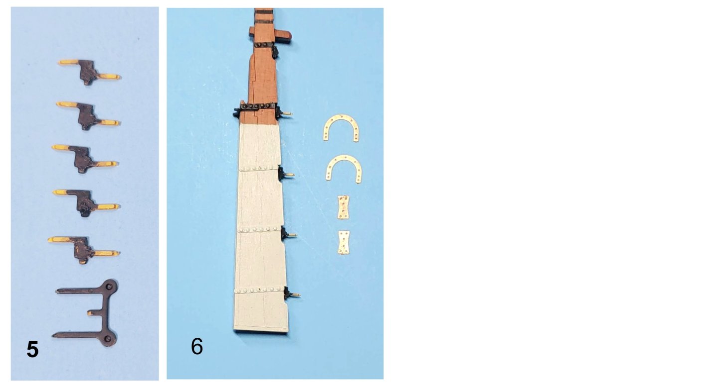
1. Rudder and the two outer patterns. This will make the usual sandwich arrangement providing detail which I would not be able to as neatly achieve on my own. 2. Sandwich glued and clamped. 3. PE brass gudgeon and pintle straps. 4, PE straps installed on the rudder using brass pins thoughtfully provided in the kit. These are cut short so that pins can be inserted from both sides. Steady hand needed to insert these. Loctite CA gel control used here. I like this glue as it can penetrate well, yet is easy to control. 5. PE brass gudgeon/pintle hinge patterns and PE spectacle plate. These hinge patterns are two dimensional, but enable precise alignment when installing the rudder; a fair tradeoff I would say. I was not planning on being able to turn the rudder anyway. 6. Hinge patterns and spectacle plate installed on the rudder. I dry fitted the rudder on the model after each pattern was glued in before the glue set to insure proper alignment of the pins. PE brass horse shoe and fish plates. These have been painted copper (Vallejo Copper), and look more like copper to my eye than they do here. Now to install them.

-
Wow!! What a great job you have done with the bowheads! Yours is the only bowheads with this configuration I have seen on any wooden model build other than the one by Herb Ebson a photo of which which I posted above. Congrats!!
-
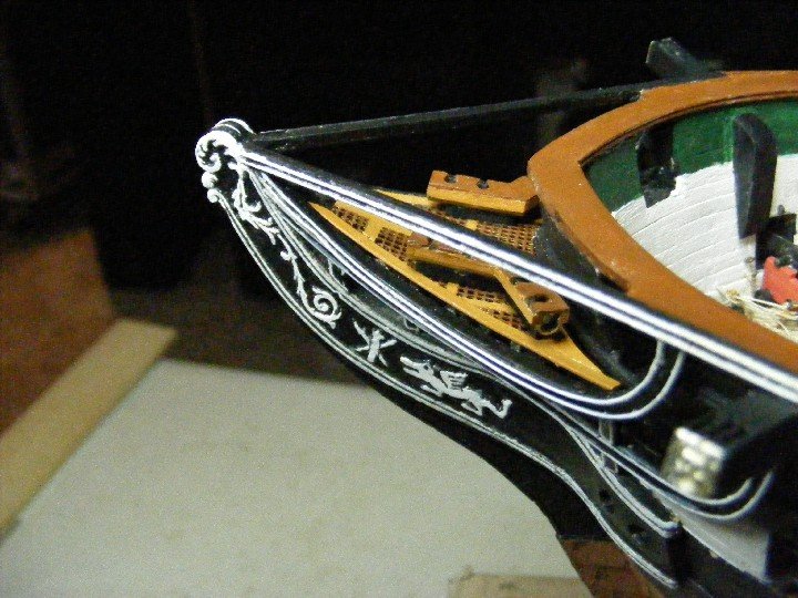
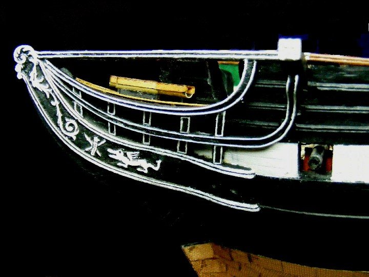
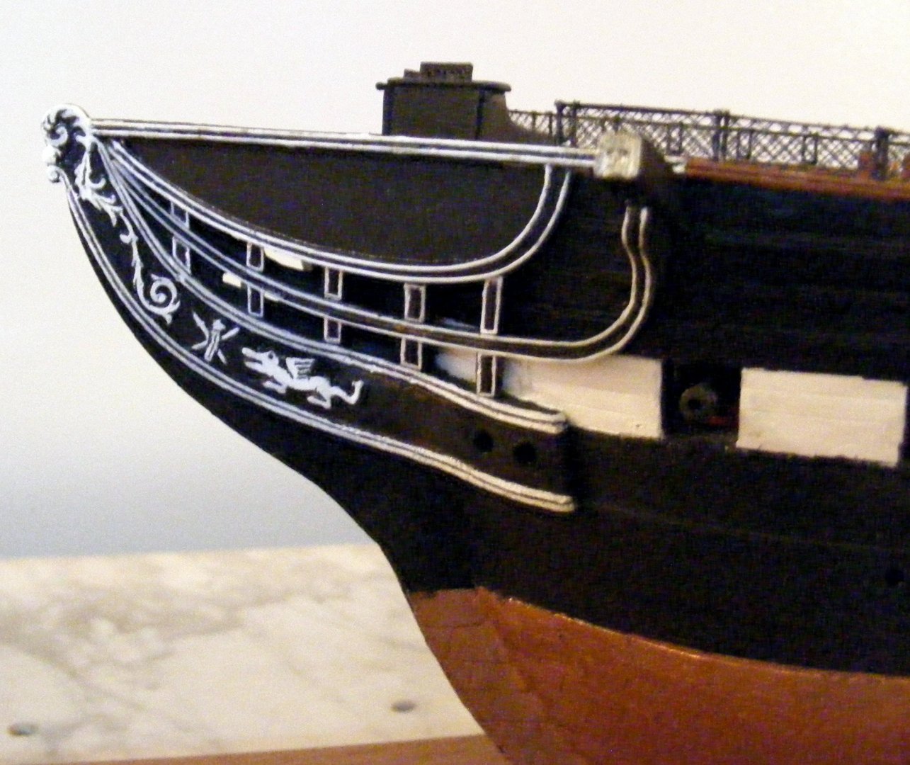
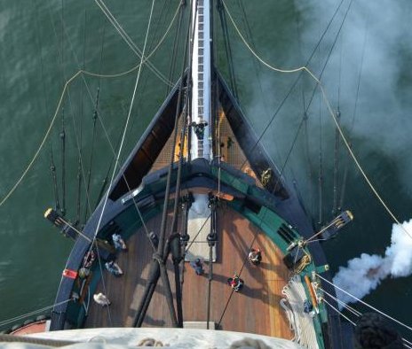
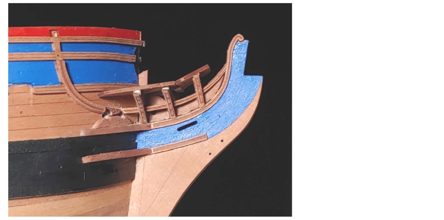
First, some definitions. The straight rail which extends from the cap rail to the billet head is what I call the false rail. The rail below that is what I call the main rail. The lowest one that curves upward to become the cathead knee is what I call the second rail. Looking straight down on the bow of the carved hull provided in the kit, you can see that it is semicircular. The provided PE grating is designed to fit this profile. You can see in this photo of the actual ship that this design is wrong: Accordingly, I altered the profile of the bow when I did the hull shaping. It looks like you did the same. Consequently I made major changes to the PE piece narrowing it quite a lot and adding Britannia metal strips on each side to replace the framing that I cut away: I did not cut any additional notches out of the center. I believe that it sits on top of the stem, but I cannot remember for sure. As you can see, I had to shorten the seats of ease so that they would fit into the reduced space. My intention was that the grating would curve to match the curve of the main rail. As you can see, it sits slightly above the rail. This defect was fortunately masked when I installed the carboard (canvas) covering: The bowsprit sits a millimeter or so above the grating on my model, but I see no reason not to have it sit on the grating. However, since the angle of the bowsprit is different than the grating the only contact would be at the aft edge of the grating.