


dunnock
-
Posts
532 -
Joined
-
Last visited
Content Type
Profiles
Forums
Gallery
Events
Everything posted by dunnock
-
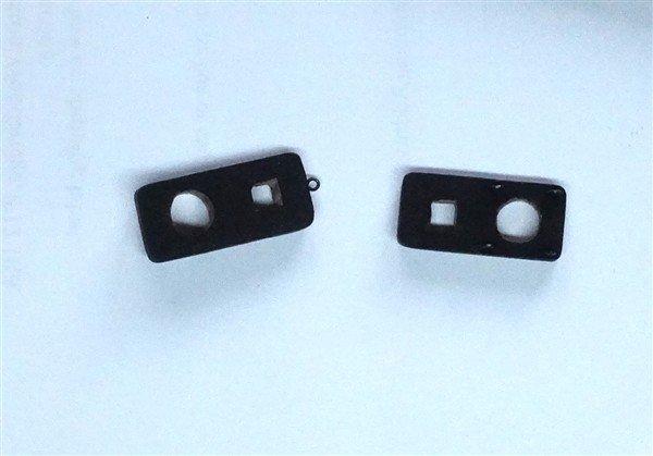
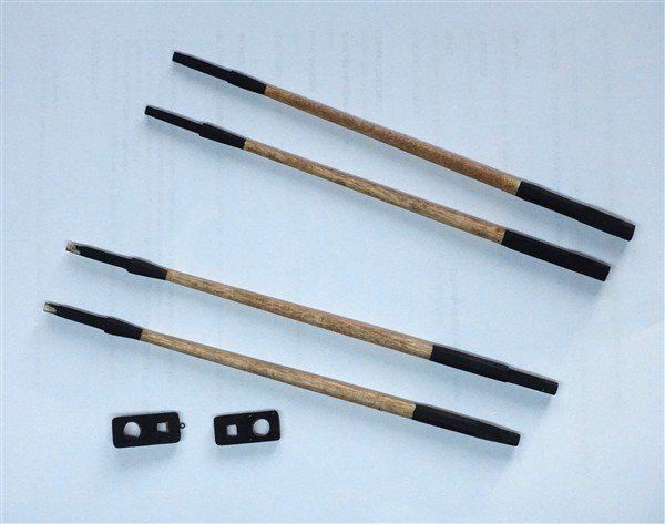
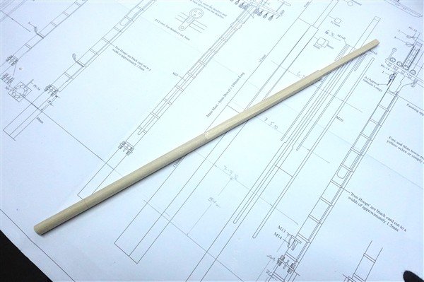
Boom and Gaff The main boom is made from 5mm ramin dowel first reduced to 4mm and then tapered. According to Lees, the outer end is ¾ and the inner 1/3 of the diameter. I have great difficulty reducing a dowel beyond 1.5mm on my lathe without it breaking out so this is where the inner end of the boom sits. The gaff, or driver boom as per the plan is made similarly from 5mm dowel. The jaws for the gaff had to be scratched from some 3mm boxwood sheet. I found that the supplied jaws needed to have a lot of wood removed for them to fit around the main mast and cheeks by which time there was no room for the holes for the parrel rope. The jaws are glued in place and then shaped to more of a taper around the boom. Three iron bands ae added, for preference, heat-shrink tube but when I forgot to add them before fixing the cleats, black card. The cleats are fitted according to the plan but when I fit the boom to the main mast and rig the sheet, I see that they are too far forward making the cleat ineffective against the pull on the sheet block. I'm not sure why that should have been. It was a simple fix to move the cleats to a more sensible position. For now, I have left the gaff out of the way, in the lowered position and tied to the driver boom while I move on to the front end. David


-
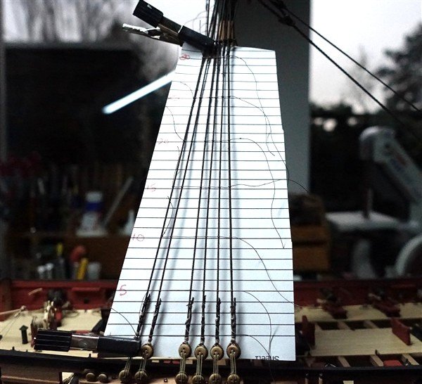
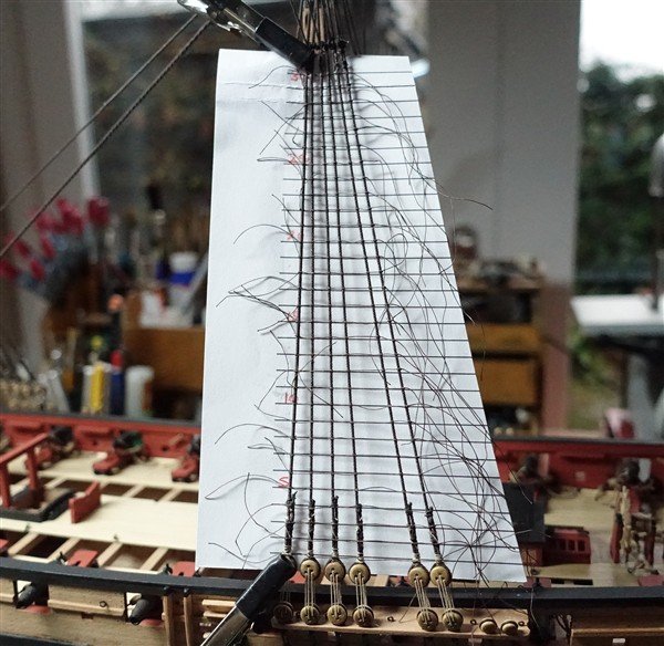
Rattling Away I followed my usual approach to the ratlines. I printed out a series of gridlines at 5mm spacing from a spreadsheet and marked every 5 lines. I use 0.1mm Gutterman dark brown thread and first tie every 5th ratline. I begin with a half hitch with an extra wrap which helps the thread emerge straighter from the knot, then its clove hitches and a final half hitch. Dabs of dilute pva hold everything in place. Nearly 800 knots later, including the futtocks, and it’s all done. Not much more to say so here are some pics... Moving on to to the main boom and gaff David
-
Thanks Ross. No the hooks are bought. They come as ready- blackened PE hooks from HiS Models. David
-
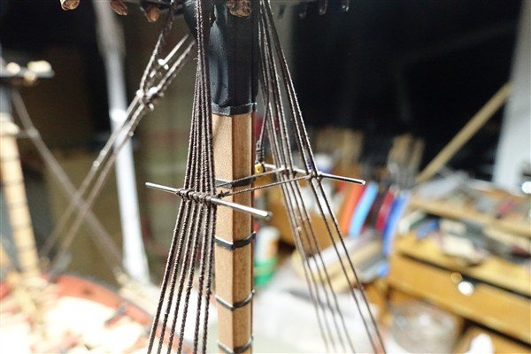
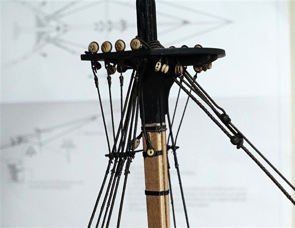
I've got a bit behind with my log but I thought that the next bit of work would be better described in a separate entry. Futtocks And All That I have made the futtock staves from 1.0mm brass rod and blackened in the normal way. They are tied to each shroud beginning with the two outer ones. According to Longridge they are fitted ‘as much below the upper edge of the trestle trees as the top of the cap is below’ Catharpins are made from 0.35mm rope and there are two per mast. I begin by seizing around one stave and then threading it aft of the mast. I tension the first catharpin and seize it to the stave. The second is tensioned to match the first before being seized to the stave. The futtock plates are blackened before fitting the 3mm deadeyes (they measure at 3.5mm) There is an excess of deadeyes supplied, necessary because the reject rate is high. The plates will need a bit of touching up to repair damage to the blackening The futtock shrouds are 0.45mm rope. They were all prepared with a 3.5mm hook seized in one end. They are hooked into the plates and tensioned while two seizings tie them to the lower shroud. I used 0.1mm thread for the seizings rather than 0.25mm suggested on the plan. Next up is everyone's favourite job - ratlines... David
-
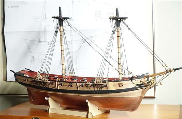
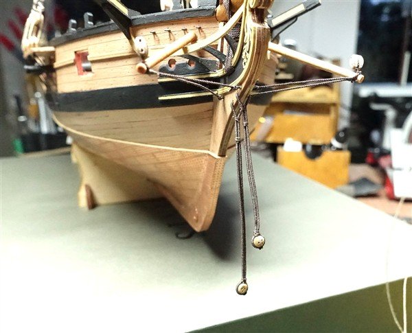
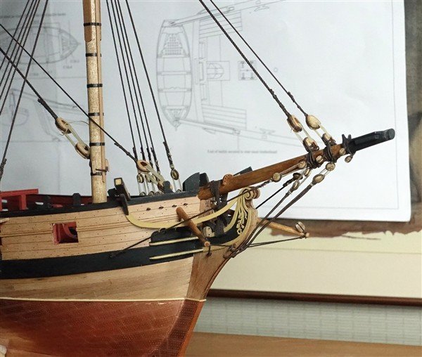
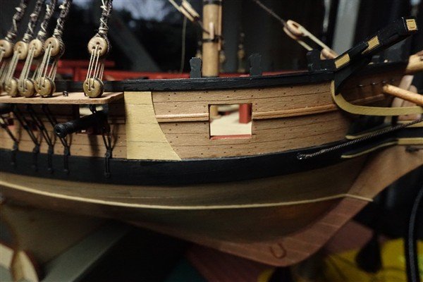
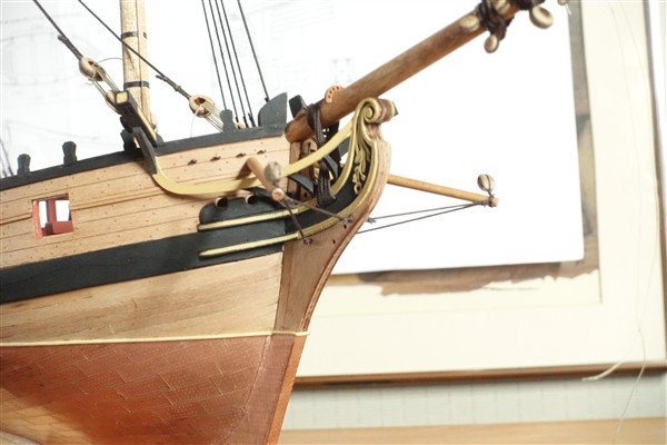
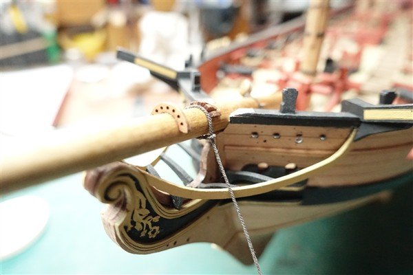
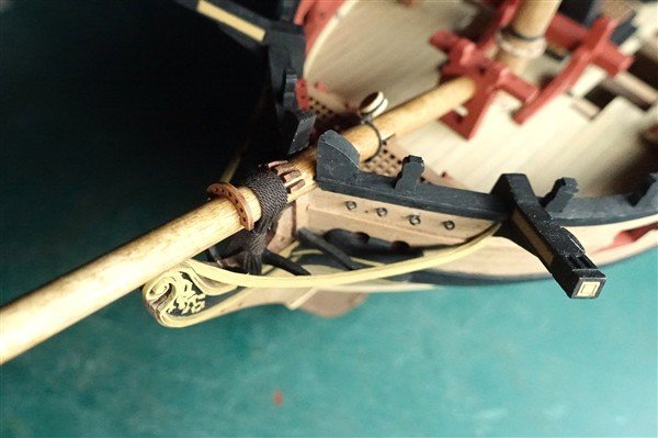
Bowsprit Rigging The bobstays are formed from a length of 0.7mm rope served for the whole of its length. The served rope is thread through the holes in the knee of the head and spliced into a loop. A 3.5mm dead eye is seized into the bight and two seizings are used to secure the stay at the prow. I had great difficulty in getting the length of the loop correct before splicing the two ends together. I also should have realised that fixing the boomkins first was going to make rigging the bobstays more awkward. There is a bit of a twist on the upper deadeye which I hope I can improve by wetting out and weighting. The shrouds are a simpler arrangement although I was unsure whether they should be hooked into the eyebolts at the bow. In end I decided to seize them directly. The shrouds are made up off model using 0.6mm rope and 3.5mm deadeyes. Anchor Lining The anchor lining protects the sides of the ship from damage when the anchor is shipped. It’s not shown on the plans but it’s a simple matter to add. I made it from 5mm boxwood strip glued together edge to edge. The general shape is standard as far as I know and I simply drew one of the correct size on tracing paper and transferred it to the glued strips. A piece of the sheer rail is cut away before gluing the lining in place. The position just forward of the fore channel is determined by the position of the anchor when shipped. David
-
Thanks Maurice. Yes she is and I'm enjoying the build but I can't decide whether to fully rig her or take an approach similar to yours (if you don't mind) David
-
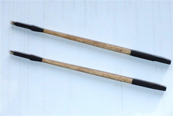
Tidying Loose Ends There seems to be a shortage of the particular colour (1712) of Gutterman cotton thread that I use for serving and seizing standing rigging. It has not been available in shops locally so while I wait for more supplies from that well-known on-line supplier, there’s some tidying up of the shrouds and the addition of the boomkins to keep me going. I check the tension of the shrouds, tightening the lanyards where necessary before tying hem off with a couple of rounds of thread. The shrouds themselves are finished of with a ‘seizing’ using the last remains of dark thread that I have: a simple clove hitch around the tail before trimming them. The boomkins are 3mm dowel tapered to 2.5mm on the lathe and a 2mmwide groove added at the end to accommodate the boomkin stays and the forecourse sheet block. A brass pin is glued in the end of the completed boomkins and located in the holes drilled in the bow. Stays are 0.5mm rope. I have 0.45 or 0.6mm. I prefer to go heavier and use 0.6mm. The 5mm single block is added to complete them David

-
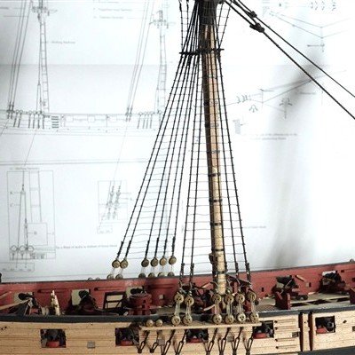
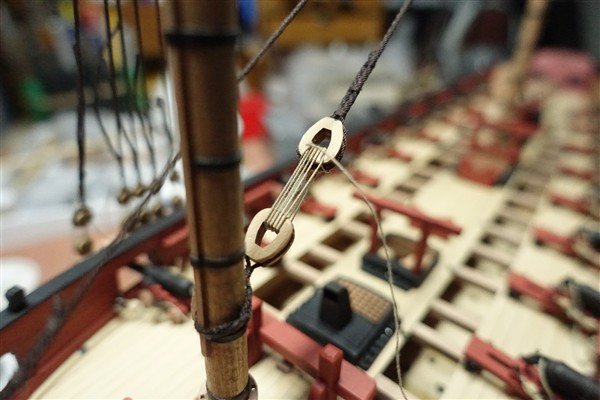
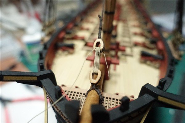
The Stays I began by removing the deadeyes from bowsprit and foremast which according to Lees had been superceded by hearts from the late 17th century. For the mainstay I used 6.5mm closed hearts and the preventer 5mm closed hearts, all from Vanguard Models. For the foremast stays I have used open hearts on the bowsprit and closed hearts on the stays. The strops are all served 0.6mm rope. The open hearts are double stropped. I had to widen the groove in the heart with a file to accommodate them. The mainstay hearts are fitted with served single strops. It would have been much easier to do all this before the bowsprit was fixed in place when I should have checked whether to use deadeyes or hearts. It also meant that I had to redo one of the 3mm deadeyes for the bobstays. The reworking completed, I could turn to the stays. The main stay is 1.35mm cabled rope and the preventer 0.8mm. They are served to about 30mm below the position of the mouse. Once served, an eye is seized into one end and the position of the mouse marked with the stay in position on the model. The mouse is made from styrene tube; 3.5mm outside diameter for the main and 2.5 for the preventer stay. Once shaped with file and sandpaper, I cover them with some nylon mesh using CA to fix it. At this scale, it’s difficult to get a good profile but I think they will be acceptable on the model. Foremast stays The stays are completed with lanyards: 0.35 for the main and 0.25mm for the foremast stays. The lanyard is tied on and given five wraps around each heart. The grooves in the hearts are pretty small, so the tricky part is preventing the wraps from overlapping and keeping them separate. Once completed and tensioned the lanyard is tied off and fixed with some dilute PVA. I'll leave the ends unfinished in case the tensions change. David
-
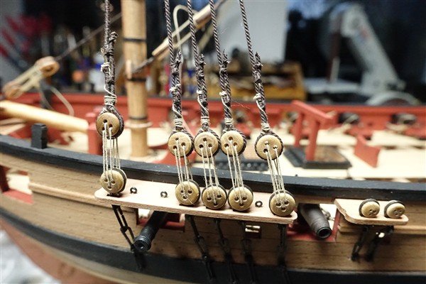
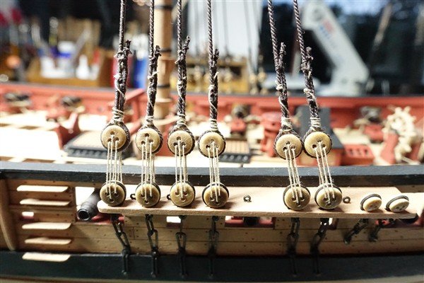
The Shrouds I used 0.8mm dark brown rope. The foremast has two pairs of shrouds each side plus one that is spliced across the masthead. The spliced shroud is treated in the same way as described for the pendents. The foremost shroud is served completely and the others to about 8 feet (scale 38mm) below the top. After serving, the shrouds are prepared on a mocked up masthead and then slipped over the real mast when completed. The mainmast shrouds are treated in the same way. There are three pairs each side so there is no need for a spliced shroud. I left the shrouds under tension overnight to remove any stretch, a step that may be unnecessary since they are put under quite a tension during serving I use the normal technique of a scrap of wood with a pair of pins top and bottom at the required distance (15mm in my case) for spacing the deadeyes. Even with a jig, I still find turning in deadeyes a fraught experience. A cross seizing of the shroud holds the deadeye. Lanyards are 0.25mm rope and needed a hefty knot to prevent them pulling through the over-large holes in the deadeyes. I will leave the lanyards and shrouds unfinished for now in case further adjustment is necessary. Thanks for looking in and for the likes David


-
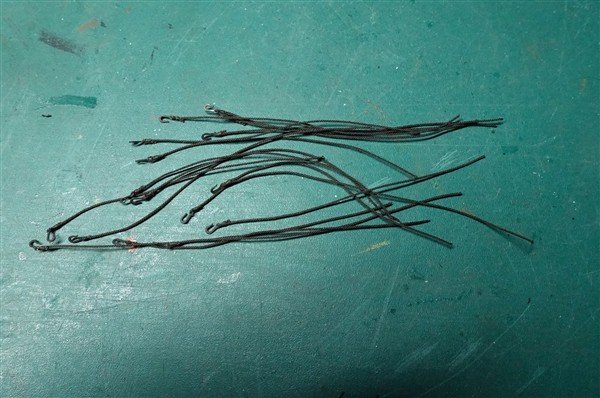
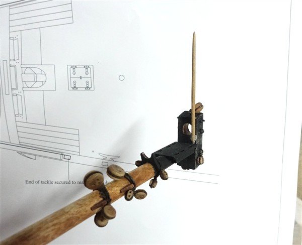
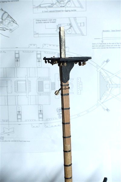
Pendents of Tackles First over the mastheads are the tackle pendents. They are spliced over the masthead and are served for their entire length. Using some spare thread, I estimate the length of the spliced section, 18mm in my case and spliced these short lengths. The total lengths of each pair of tackles is 136mm and will fall to just below the hounds. The first part of the tackle is served then the short length is spliced in. I separate the three strands and splice in two and then one strand to achieve a more gradual merge. Serving continues to the other side of the splice, the other end is spliced in then serving is completed to the end. 2mm wooden thimbles are seized into each end. The completed pendents are fitted over the masthead. This turned up under my tree on December 25th... I've had a look inside the box and I think it's going to be a challenge. I'll be doing a lot of thinking and planning before I start but I have plenty of time, there's still a way to go with Harpy. David


-
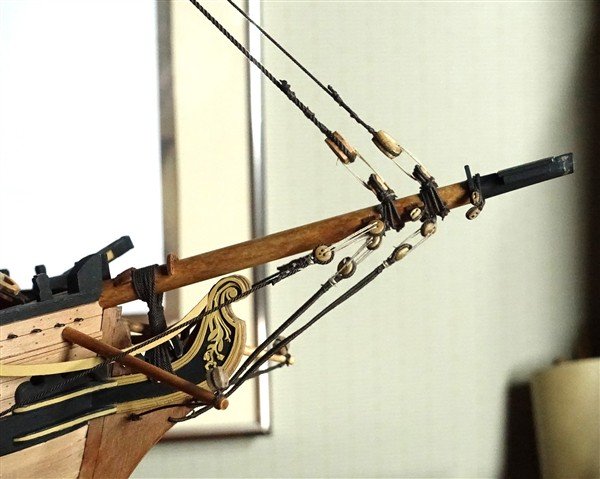
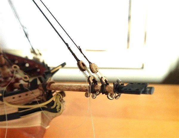
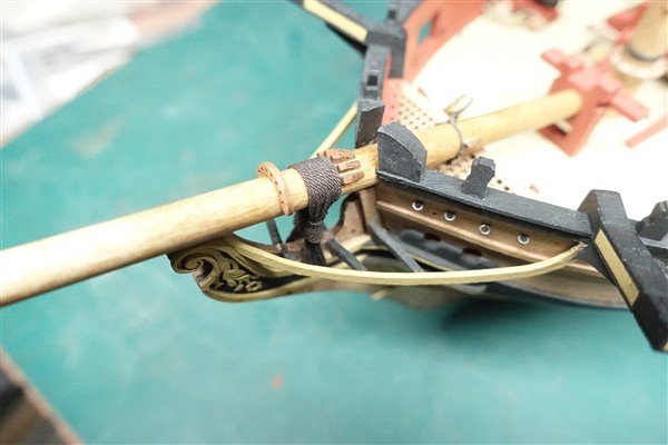
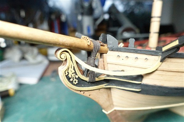
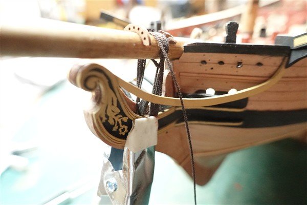
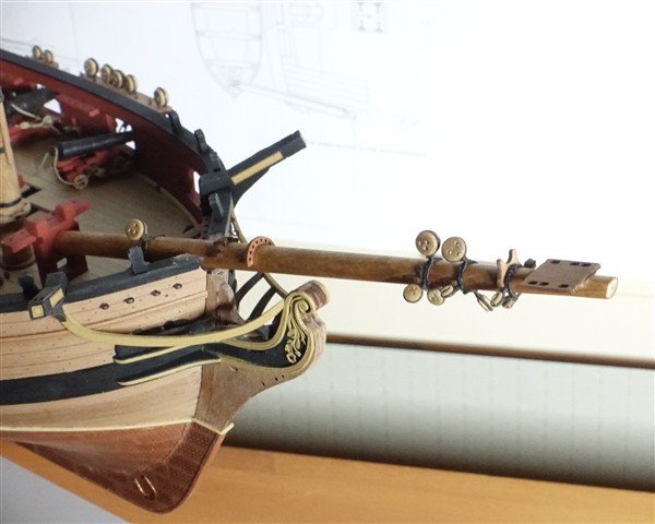
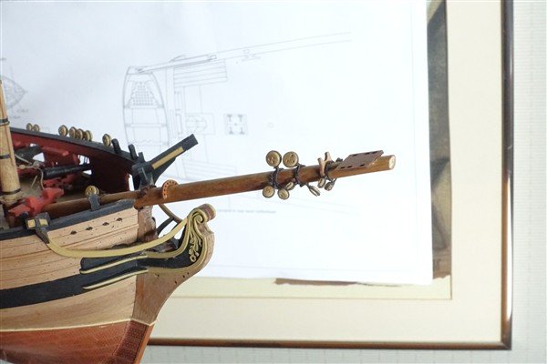
Completing the Bowsprit The cap has been cut to size. A groove is formed on the starboard side of the cap for the jack stay. The blocks and eyebolts are added to complete the cap. The cap and staff won’t be fixed in place until I’m ready to add the jib boom. With the blocks added and the jibboom made, I fix the bowsprit in place with the gammoning. I estimate how much rope I will need by making five wraps with some thread. It works out at about 1100mm so I cut 1200mm of 0.7mm rope to be sure. I begin by making an eye splice in one end and thread the other end through passing the resulting loop over the bowsprit. The eye sits on the port side. Wraps run forward on the ‘sprit and aft-wards through the gammoning slot, putting a twist in the wraps. Ten wraps fills the slot. In theory I should take ten frapping turns around the wraps but nine fills the space. Finally the end is seized to the first wrap using 0.1mm thread. I can now move on to rigging the lower masts, beginning with the tackle pendants. David
-
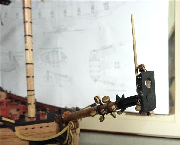
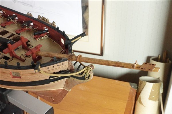
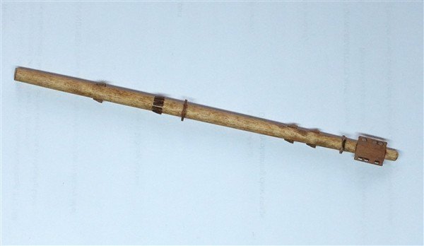
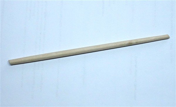
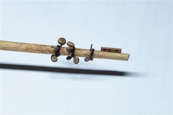
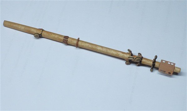
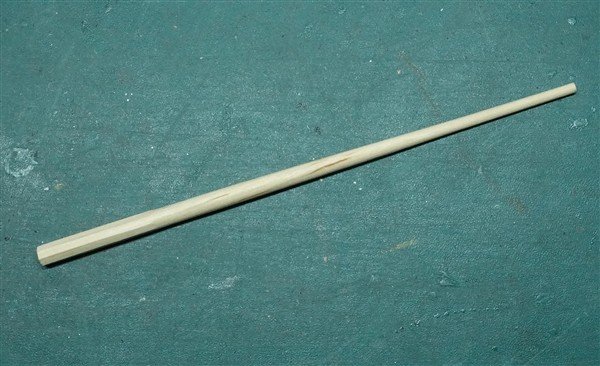
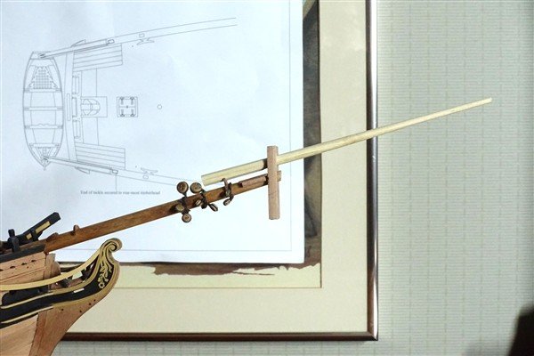
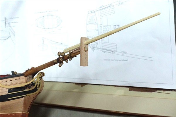
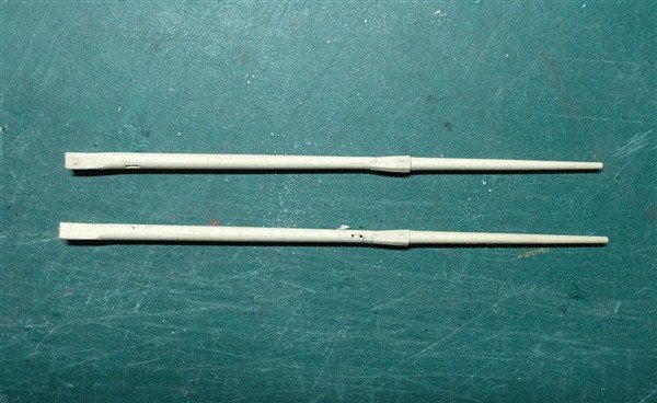
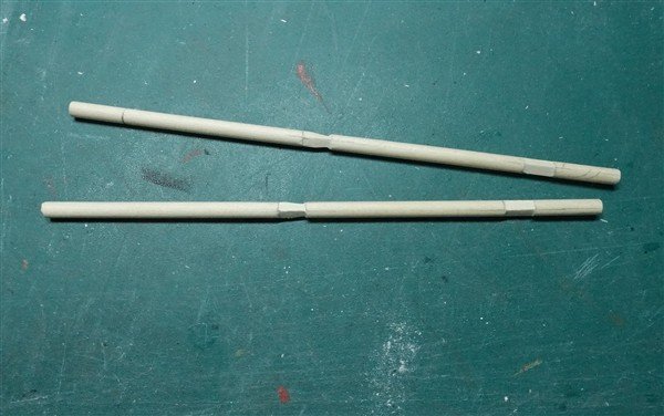
Bowsprit The maximum diameter of the bowsprit is at the bed: where it sits on the stem and according to Lee’s, is about the same as the main mast at the gun deck. I have settled for a compromise of just under 7mm with a taper to 6mm at the step and 5mm at the cap. I have temporarily removed the knightheads to sand back the hole for the bowsprit at the stem. The gammoning cleats, jib saddle and various cleats are added and then the variety of blocks and deadeyes. I have made bee blocks to go under the bees using some 2mm pear fret. First and most straightforward is the main preventer stay deadeye. I measure the length of rope needed to go around the deadeye and bowsprit and the required length is served. In reality I can serve three strops in one length on my machine. I’m using 0.4mm polyester thread served with Gutterman cotton. The deadeye is siezed in to the bight of served rope and the tails of unserved polyester are threaded into each other around the bowsprit to form a false splice. Each single or pair of blocks is secured in similar fashion (life is hard enough without attempting to fit more than two blocks on one strop). Jibboom The inner part of the jibboom up to the cap is an octagonal section. I used an 8mm dowel which I first planed square and then formed the octagonal. After further planing and sanding, the round section taper was finished on the lathe. This basic form of the jibboom is now used to check the measurements for the bowsprit cap. Bowsprit Cap The cap is scratched from some spare 4mm pear wood. I have made it 20 x 10mm: wide enough to accommodate the flying jib and jack staff. The holes for bowsprit and jibboom are formed at an angle so that the cap sits at right angles to the waterline. The cap will be cut to final size with top and bottom cut to follow the angle of the bowsprit before adding eyebolts and blocks. David
-
Thanks for that Geordie. Good of you to say so and glad that the log is of some help
-
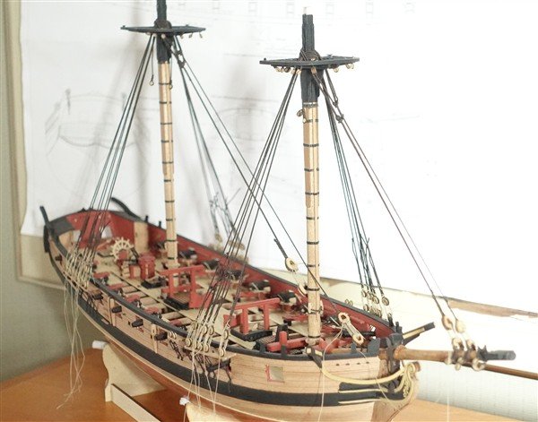
Topmasts Cont’d The top-rope sheaves and hole for the fid are cut. I needed a bit of a fiddle to make the block fit through the hole in the top by filing it back up to the fid. I then had to re cut the octagon. The ramin is stained as before with a mix of antique pine and teak. I couldn’t use the caps provided in the kit so made them anew from the spare 4mm fret. They are a little larger than supplied at 24x11mm and correspond more closely to dimensions given by Lee’s. I cut a square 3.5mm for the main mast tenon and a 6mm round hole for the topmast. There are a pair of cheek blocks fixed to the head of each mast. The 2mm pear bolsters supplied for the main mast top, which I haven’t used, seem to be the ideal size. I cut two sheaves in each and will glue them to the mast once the cap has gone over and the mast is in place. The top pair are the topmasts that I rejected earlier but have finished them as good enough for spares to sit on the deck. Top Gallants These an easier proposition than the topmasts. According to Lees and to Petrejus's Irene there are options of octagonal or round sections at the base but either way, a square block is required. I have taken the simple option of a round pole. The masts are cut from 5mm dowel and a 3.5 x 9mm square section is formed first at the heel. A further tapered 4mm square section at the hounds is also cut before sanding in the taper on the lathe. The hounds are finished to an octagonal section. A hole is cut athwartships for the fid and a sheave cut fore and aft just below the hounds for the yard tie. I was able to adapt the topmast caps to accommodate the square section tenon on the topmast. Oddly the holes for the eyebolts on the underside of the cap are pre-cut but run through the cap. A bit of acrylic filler soon fixed that. With all the masts in place Harpy is now quite tall. I hope there's enough headroom on my shelf! Thanks for the likes David
-
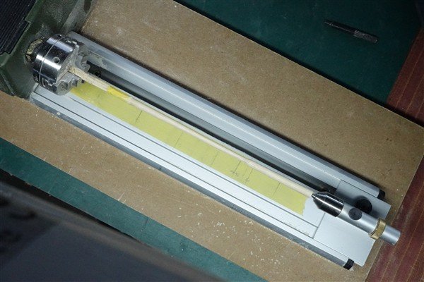
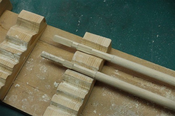
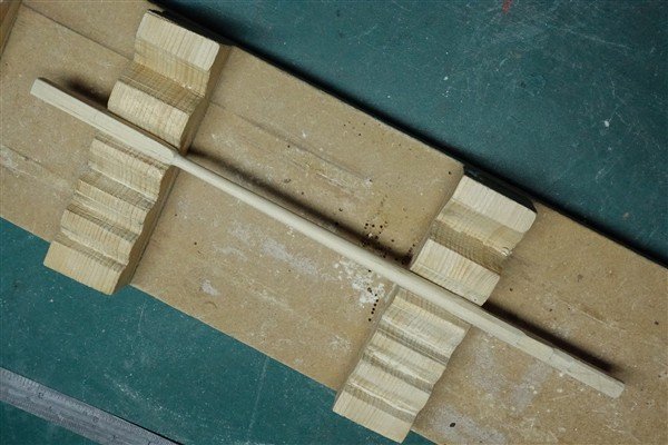
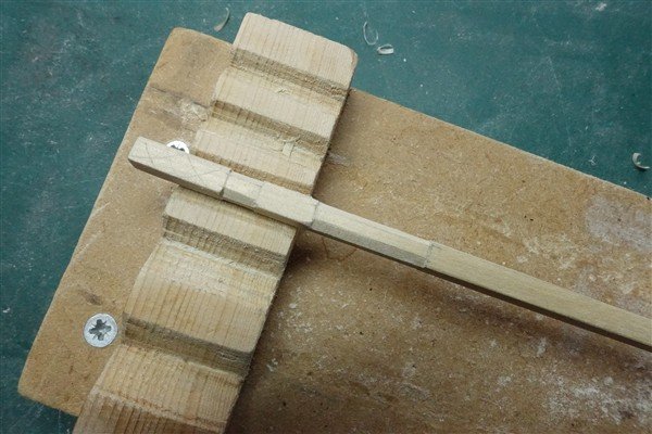
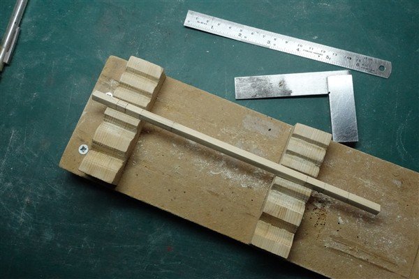
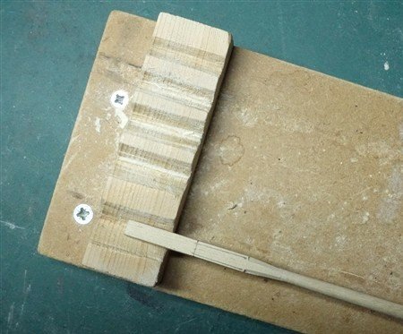
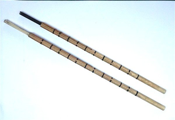
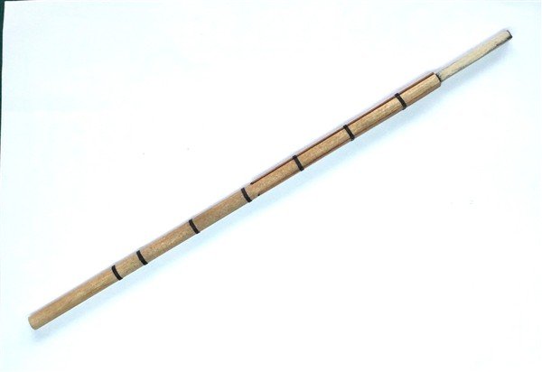
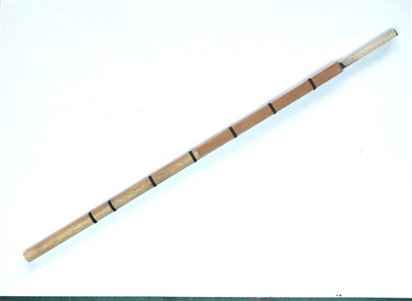
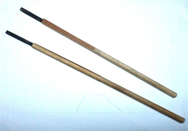
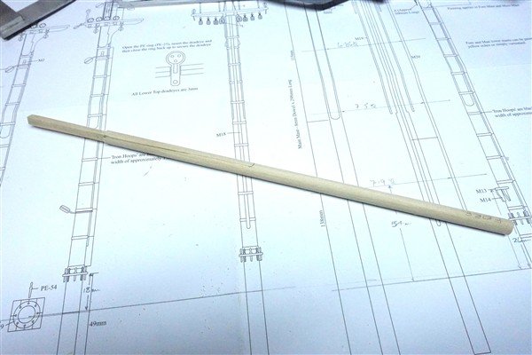
Topmasts The plans are a simplification of the base of the mast with no block or octagonal sections and I redrew them to the proportions given in Lee’s. I start with 8mm ramin dowel and squared off the section between main mast top and cap at 6mm and then cut the octagonal sections using the 7:10:7 rule. This done, I use my lathe to reduce the main part of the mast to 6mm and then taper to 4mm at the hounds. I wasn't happy with the results, especially the main topmast so decided to remake them using a different route. I began with the same 8mm dowel but using a plane and sanding sticks, made the entire length 6mm square. I marked out the octagonal and square sections of the block and heeling using the 7:10:7 rule and cut the octagonal sections with chisel and sanding stick. It's difficult to measure such small faces accurately and the diagonal was coming out oversized. The face of a 6mm octagon is 2.48. I set this on my calipers and score down the partially cut diagonal faces and then sand back to the correct width. I cut the hounds into a square section of 4mm at the base increasing to 6mm at the beginning of the head. The bulk of the mast is prepared for the lathe by roughly sanding it from square to octagon and then to a hexadecagon before finally sanding it round on the lathe. The hounds are finished to an octagonal cross section as before and the head cut square with a taper from 4 to 3.5mm at the cap. Finally the cap tenon is cut at 3mm square. It's left slightly long to allow for the final trimming. I have marked the rough positions of the fid and also the top and bottom top rope sheaves. I'll remove the waste wood at the base of the masts after these have been cut. This is much longer process than trying to work with a round section but I’m much happier with the results. With a bit of extra work, my previous efforts might serve as spare masts on the deck. David
-
Thanks Geordie
-
Thanks Ross
-
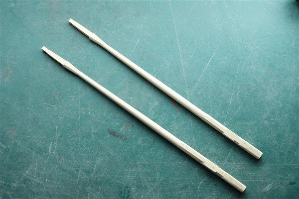
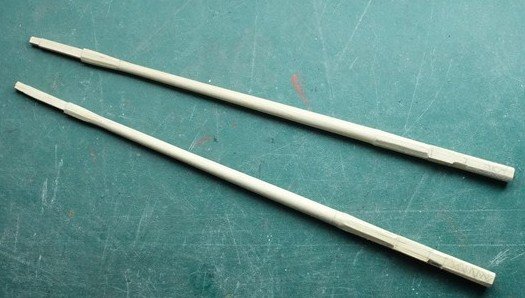
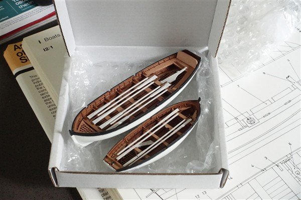
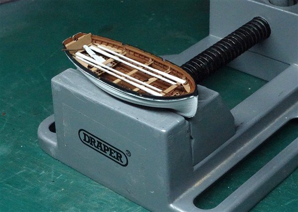
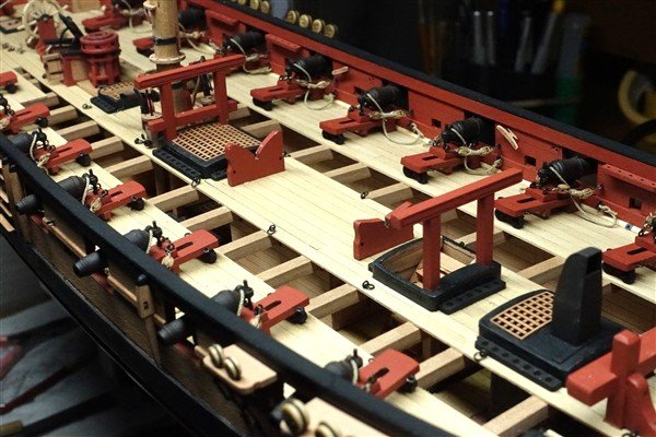
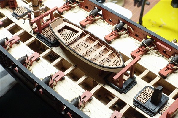
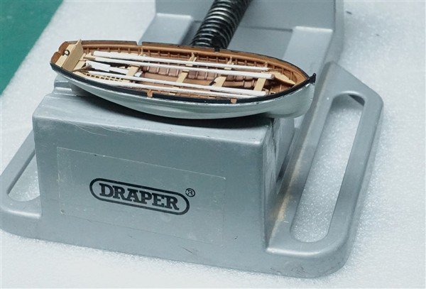
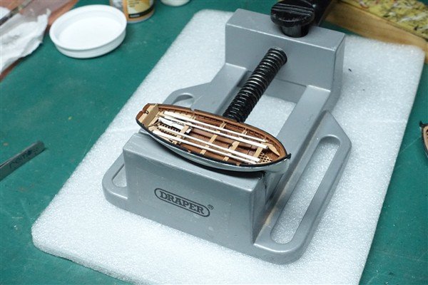
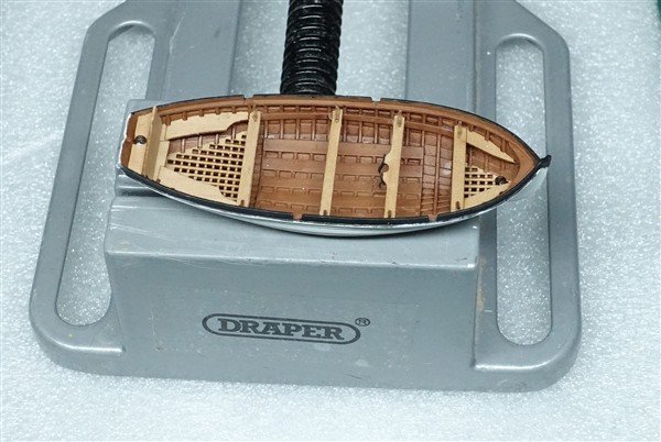
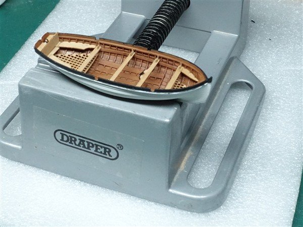
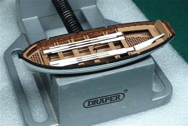
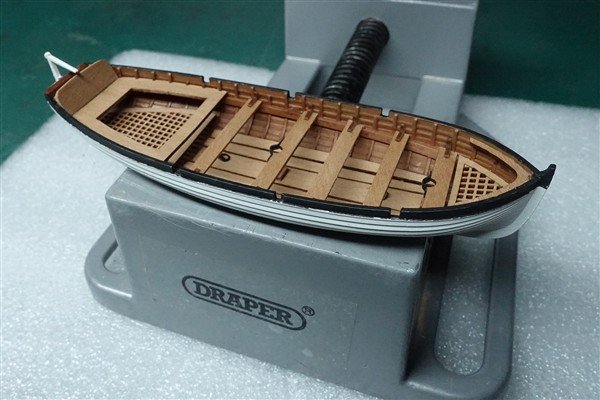
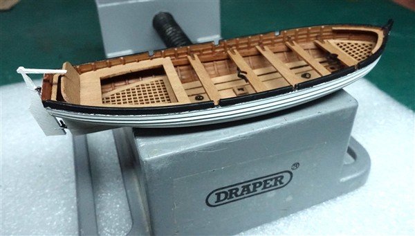
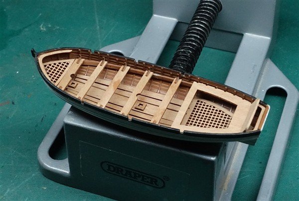
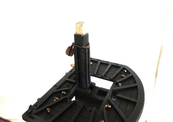
Ship’s Boats Before going much further I needed to position the boat stands for the 22’ cutter so I decided to make up both boats. I painted the interior with a mix of browns and ochre until I was happy with the colour and then added a colour wash of dark brown. The exterior is painted using off-white and iron-black (as an off-black) for the wash strake. The interior fittings of the 24’cutter are laser cut 0.8mm pear. To help with the alignment of the forward mast step, I began by placing the forward grating and thwart. I used a cocktail stick to align mast step and thwart. The other four pieces of footwalling were then glued in place. I scraped off the paint and used thick CA but still had trouble achieving a decent bond. Damping the wood helped. Once the footwalling was in place, I could fit the stern gratings and stern bench. I added lifting rings as a bit of extra detail. The thwarts were a puzzle. Only four were supplied but the single-banked oar arrangement suggested five were required. I cut the fifth from the same 0.8mm pear sheet. The thwart at the main mast was added first followed by the other four. I copied @Blue Ensign's idea for the rudder and added a pintle and a ring to the stern from which to hang it. I haven’t used the provided oars. They are undersized according to May’s Boats of Men of War and I wasn’t sure of the shape. I had some brass etched ones from a previous model which, although still a little short, I preferred their look. The boat stands needed to be lifted with a strip of pear to raise the boat above the deck gratings. They are only pinned in position at the moment. I positioned the stands centrally between the hatches but looking at the photo below I may have to move them back a tad to clear the forward hatchway. The parts for the smaller cutter are very delicate. The footwalling is moulded into the hull so gratings are added first. The sternboard posed a problem in that it appeared oversize by about 1.5mm. It maybe because I placed the stern grating too far aft and therefore the sternboard, to sit in line with the grating, was also too far back. I cut the sternboard to size but the thwart split and was eventually cut out completely and replaced with a separate piece. At least the join at the rear could be covered by the backrest. Both boats are now put to bed until towards the end of the build. Thanks for looking in David
-
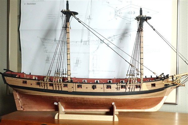
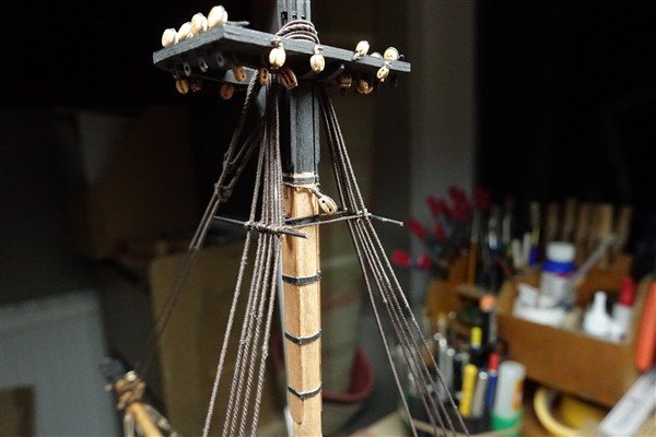
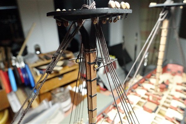
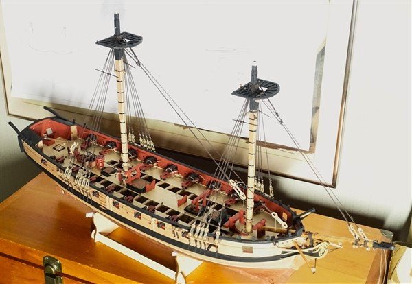
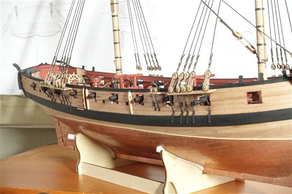
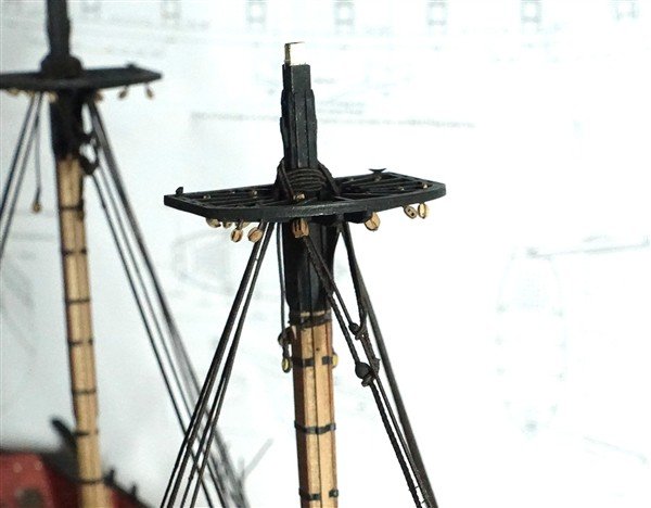
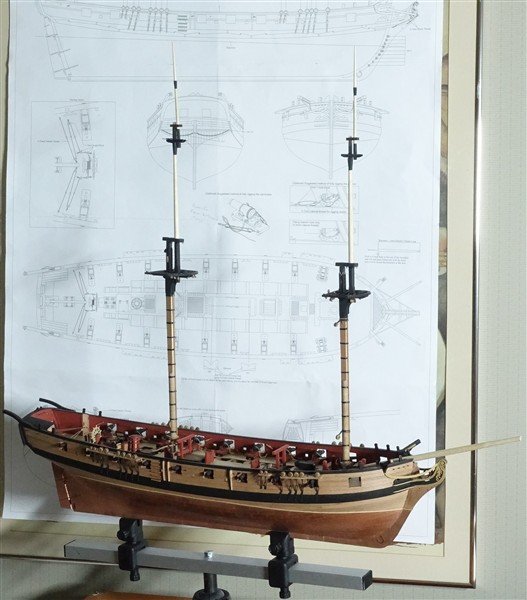
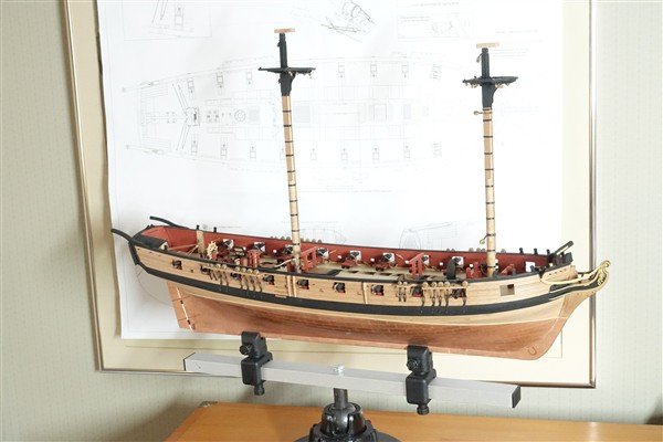
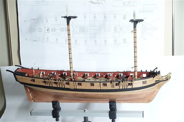
Lower Masts cont’d With the tops fitted, details at the head can now be added. The bolsters are made from some 2mm fret and cut and rounded off. They are cut a little longer than those supplied. The hoops are cut from heat-shrink tubing and spaced according to the plan: four on the foremast and five on the main. Eight battens are fitted around the head to reduce chafing of the shrouds and other ropes I cut them from 0.8mm fret which allows enough depth for them to be notched over the hoops. With these details added, I have painted the head and mast to the bottom of the bibs in matt black. A 5mm block is stropped to the foremast head for the main topmast preventer stay using 0.5mm served thread. The main difficulty is judging the length of thread required. I served 50mm of thread leaving a short length unserved at either end and siezed the block in centrally. The unserved section is threaded through to make a false splice, tightened against the mast and tied off. The boom topping lift runs through a 5mm block at the head of the main mast. It is siezed to an eyebolt and glued into the mast. I made the tenon 4mm square to fit into the tops and therefore need to cut new caps. They are made from 4mm pear, using the kit piece as a pattern for size. The holes in the main mast cap also need to be cut a a slight angle so that it sits parallel to the top and the waterline. The corners of the cap are rounded as per the drawings in Lees. I’ve still to add eyebolts and the block on the main cap. This will wait for the fitting of the topmasts when I can finish the forward hole in the cap. The violin blocks for the yard lifts will be made up and added at the same time. This is Harpy as she stands. The masts don't need any glue, they are just slotted in. Thanks for likes and comments. They are much appreciated as always. David
-
Just catching up on your D-of-K Glenn. She's looking very nice. David
-
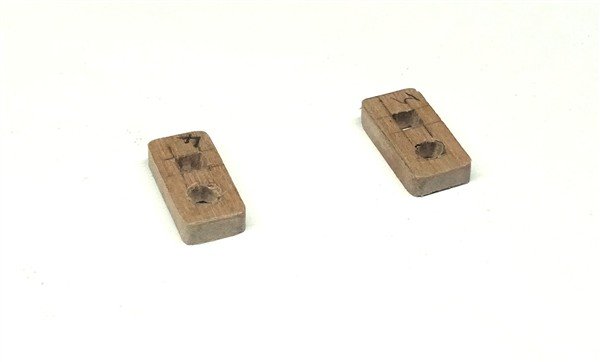
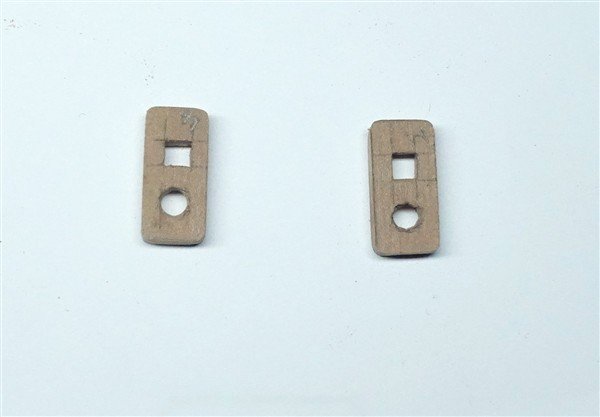
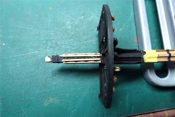
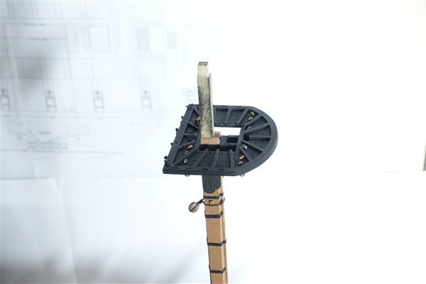
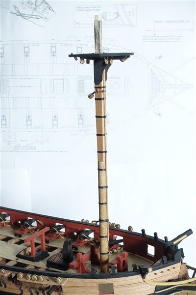
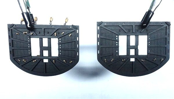
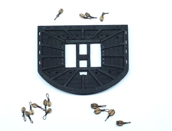
Lower Masts cont'd Cheeks and hoops are added and then the front fish and the remaining hoops. I checked the angle of the main top which must sit parallel to the waterline before the bibs are glued in place. The foremast is not raked and the top sits squarely on the mast. I drilled 0.9mm holes ready to take the lower yards which will be pinned in place when the time comes and I also drilled a 0.5mm hole in the after side of the main mast at the hounds ready to take the block for the throat halliard. The foremast has a 5mm single block on a strop just below the hounds for the main topmast stay and a 5mm deadeye set at 53mm above the deck for the main stay. Strops are 0.5mm thread served with Gutterman cotton thread. Before going further, I need to complete the tops... Tops The mast tops fit together very nicely: trestle trees and crosstrees slotting together and then into the deck. It’s easier to add blocks, eyebolts and cleats before fitting the tops to the mast. The plans show the blocks for tacks and sheets suspended from eyebolts in the crosstrees but according to Lees, they were suspended from toggles on the deck. The main mast has six blocks and the foremast twelve. There are also four single blocks on eyebolts at the rear of the fore top for the bowlines. I checked how long the strops need to be to hang clear of the crosstrees. The strops are made from 0.4mm linen thread. I siezed the toggle loop around a 2mm dowel with 9 wraps of Gutterman cotton thread. The block is fixed with a simple knot and some dilute PVA added to seal it. I make the toggle overlong from 1mm square boxwood, rounded and reduced slightly by scraping. Once the blocks are in place, the toggle is cut to size with a micro chisel. The tops can now be fixed to the masts. I rechecked that the tops sit parallel to the waterline before glueing in place. I made some slightly longer bolsters than the kit provides from some 2mm pear cut from fret. It is rounded off and glued to the trestletrees. Before I finish the head of the masts, I need to get my paintbrush and some matt black paint out. Thanks for looking in and the much appreciated likes. David

-
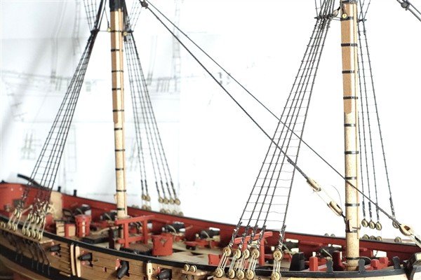
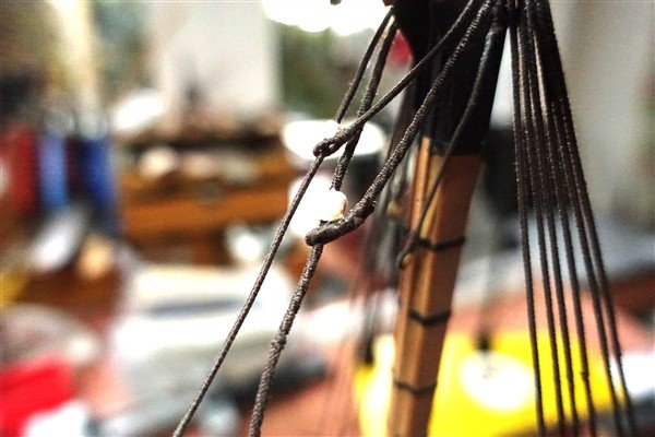
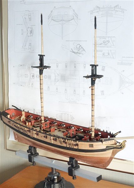
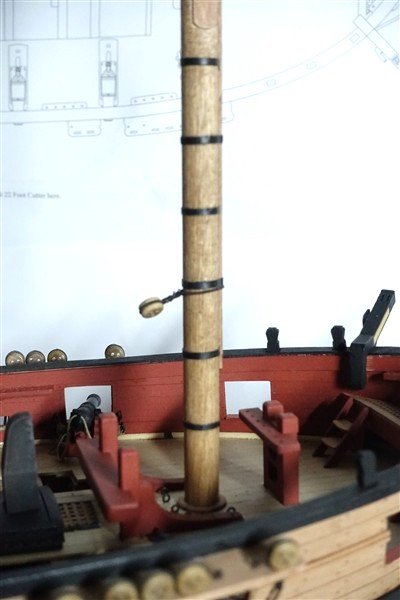
Lower Masts I considered applying the appropriate tapers as given in Lees (I assume that they are valid for brigs too) but looking further ahead, it would have meant a few other modifications. The mast at the head is given as scale 6mm so cheeks and bibs would have to have been reduced and maybe the tops too. I decided to just go with the plans. The masts begin with 8mm ramin dowel and the 5mm square section for the head is marked up. I use a mini chisel to remove the bulk and then sand to final size, regularly checking for width and squareness. Fore and main masts are the same differing only in length. A flat is added to each side of the mast to take the cheeks. I mark the position of the cheeks and remove a little of the wood with a chisel but mostly I use a sanding stick to reduce the width between the flats to 6mm. The cheeks are glued in place. I have stained the masts with antique pine wood stain mixed with a drop of teak to even out the colour between ramin and pear – not entirely successfully. There are a number of ‘iron’ bands to add over the cheeks which I cut from black card. Further hoops will be fitted once the front fish is added. The foremast is similarly ‘hooped’ I’ve also begun work on the tops but that’s for another post. David
-
You're too kind Andrew, thank you
-
Thanks very much Chris and Geordie for your generous comments David
-
Thanks Bob, that's very kind of you


