dunnock
-
Posts
529 -
Joined
-
Last visited
Content Type
Profiles
Forums
Gallery
Events
Everything posted by dunnock
-
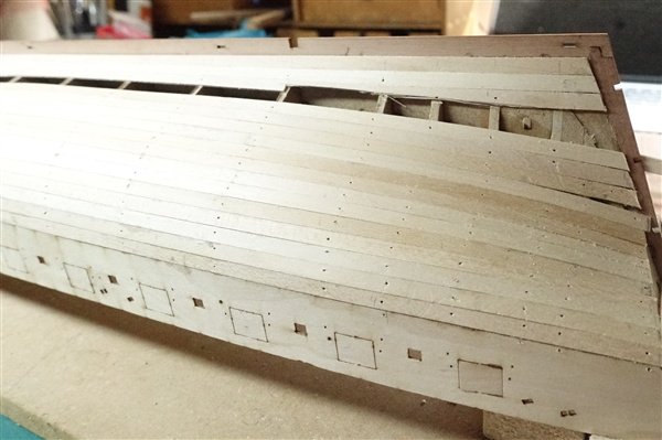
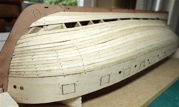
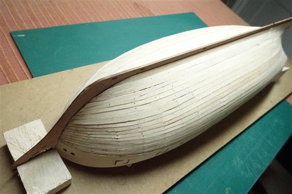
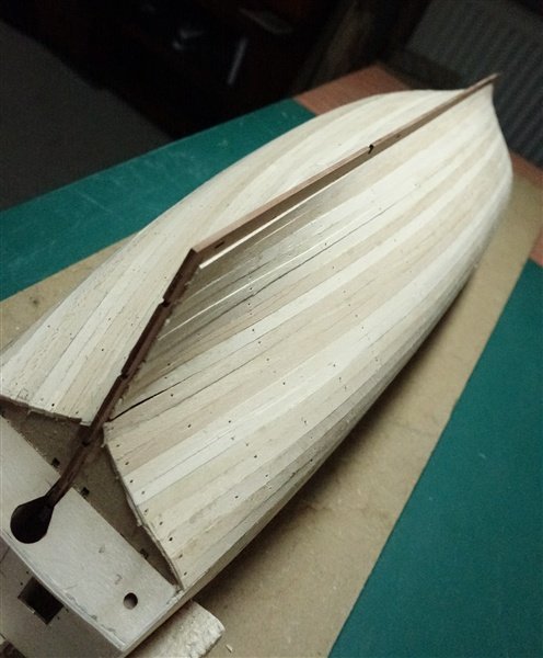
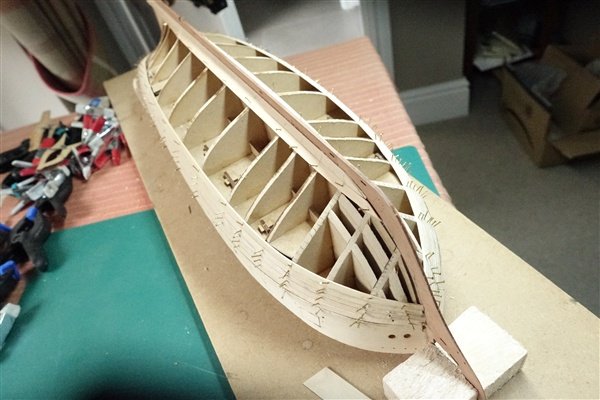
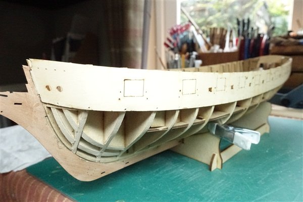
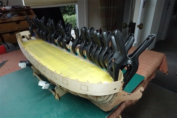
First Planking Cont. A bit of a break in work on Harpy. I've been visiting a friend in Preston with the most incredible model railway based on Preston station in 1938 and followed by a week staying with friends on the Isle of Man. A couple of afternoons and evenings and the first layer of lime planks is complete. There is some work to do, especially around the bow on the port side where I think I made a mistake early on. It meant that some of the edge-bends were a bit extreme and I had to add a wide spiled plank. The final strake was a bit of a mess with a wide plank required at the bow and stern and a thin piece in the middle. Overall though, I’m happy enough. Some lighting angles are not very kind; a lot of sanding and some filling follows. Thanks for following and support. David
-
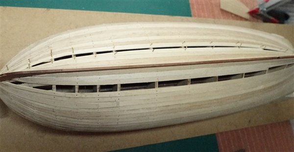
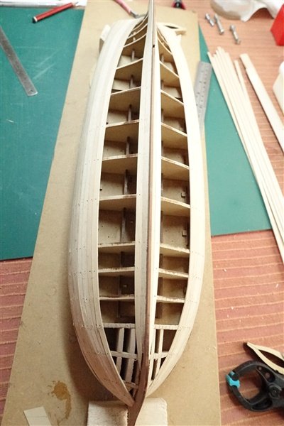
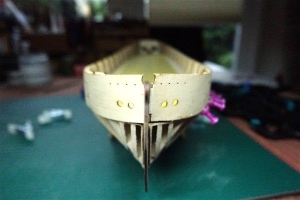
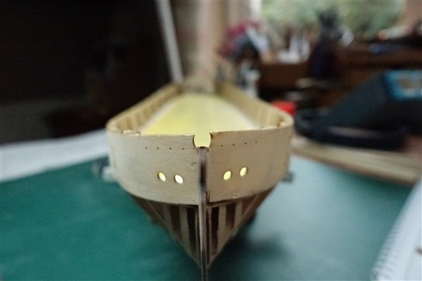
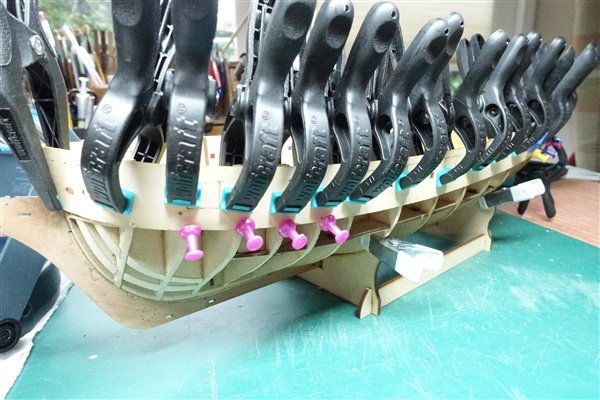
First Planking The first layer of planking with 5x1mm lime is going steadily. I used tick strips to measure the width of the plank at each bulkhead. Each plank is tapered to 2.5 or 3mm at the bow and gradually runs to full width between bulkheads 6 & 7. The planks are bevelled before glueing and pinning. After five runs down from the gunport patterns I fitted the garboard strake and the one above. With eight runs completed, I’m nearing halfway. Some edge-bending is needed at the bow but I’ve not needed to use any spiled planks yet. Onwards and upwards (and downwards) David
-
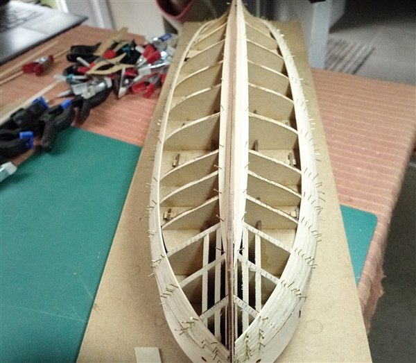
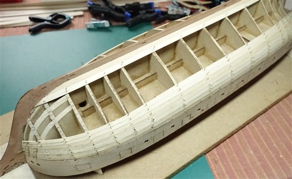
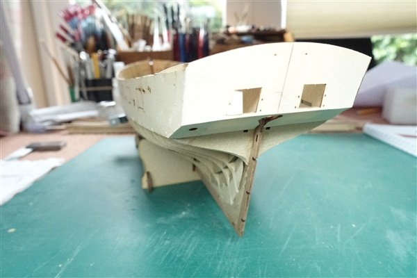
Thanks to all for the likes and comments Preparation for First Planking I spent a happy couple of hours in the sunshine fairing the hull . There was even sufficient breeze to keep the dust down. The inner patterns for prow, stern post and keel are added next. The prow needed some sanding to make it fully seat into the slots between frames. Before glueing in place, I tapered the leading edge of the knee of the head. I don’t have exact measurements of the taper but drawings in Longridge and AoS Diana show a reduction of about 1/3. To achieve this would mean sanding away the leading edge of the pattern completely when the two 1mm thick outer pieces are taken into account. I thought that too extreme for this modeller and reduced it to 1mm; sufficient to see a taper. The stern post and keel also needed a slight touch of sanding to achieve a tight fit. There was a 1mm gap between prow and keel which I filled with a sliver of pear. Sorry, I forgot to take pictures of a lot of this stage. I gave the gunport patterns a short soak to accommodate the curve around the bow. I couldn’t get the two patterns to fit in the slot at the prow so enlarged it to give more space. I also tapered the leading edge of the two support pieces that are glued to the prow. Even so it was a tight fit and I didn’t entirely succeed in getting both parts to meet. The first patten went on easily, glueing along the false deck every three or four bulkheads clamping and pinning the lower edge to each frame. The fit was perfect at the stern and required only a light sand. The starboard side had to be refitted because the forward end slipped out of the slot and there was about a 1.5mm overhang at the stern. A second attempt was a great improvement but still required some sanding to bring it flush with the counter and transom pieces. As a final step before planking, I made a support for the upturned hull from a piece of mdf and scraps of balsa. David

-
Hi François, I use a Pigma Brush to blacken one edge of each plank. David
-
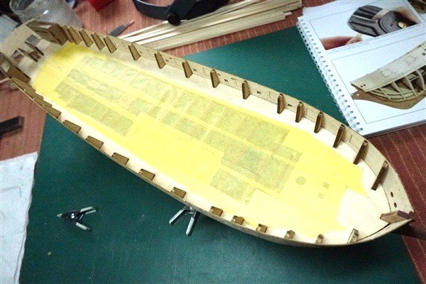
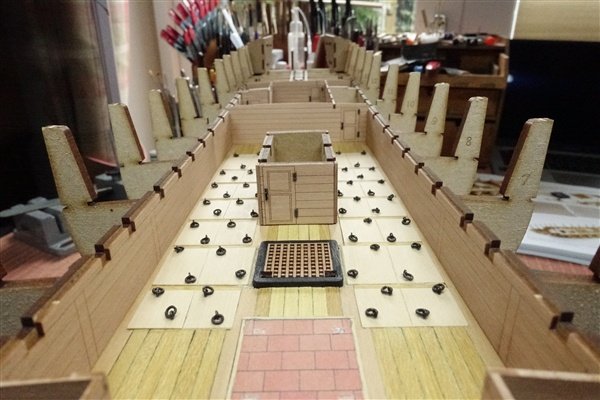
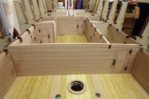
Completing The Lower Deck I have made some of the gun deck centre line fittings but I'll save that for a more appropriate point in the log The hinges and handles that I was waiting for have arrived from Syren and I can continue with fitting out the lower deck. The small Syren handles are added to the pear cabin fronts using small dots of CA gel and the paper hinges with PVA. They all slot together easily but the side walls need clamping to stop any risking of warping. Once in place, I gave them a couple of coats of diluted matt varnish. The beams are all sanded to remove the char and dry fitted. There was only one slot that needed a bit of attention but only because of a slight overlap from one of the cabin pieces. Carlings, mast partners and capstan base are added and alignment checked with scraps of dowel. The ship’s stove is 3D printed and nicely detailed. I painted it iron black and dry-brushed it with pale grey to bring out some highlights. It’s quite subtle. I glued it in place on the hearth with CA before the final carling pieces are added. The ply sub-deck clips in place after a bit of fiddling and lies nicely flat. Next up is to complete fairing the hull. The deck is covered in wide masking tape to keep the majority of dust out. Time to make some more dust... David
-
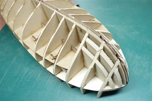
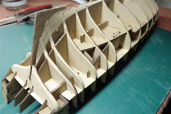
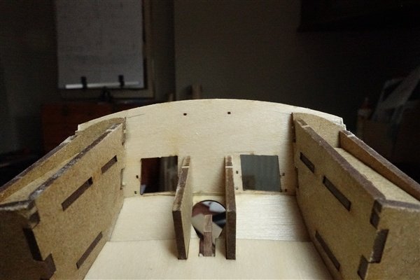
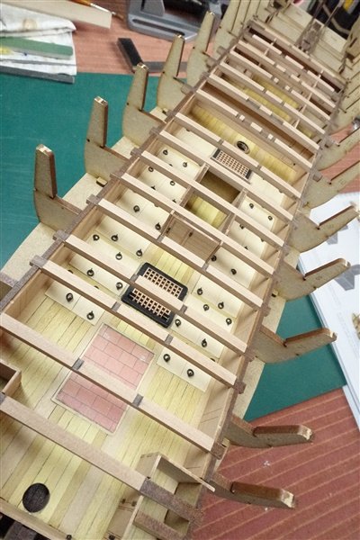
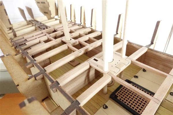
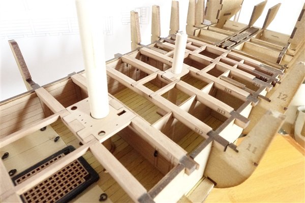
Completing the Hull Structure The four bow filler pieces are bevelled to the laser etched marks on each piece and glue in place. The final two pieces atop the bow section are also added. At the stern there are two pieces to add which slot either side of the keel section to support transom and counter and to provide a firmer base for the final bulkhead which is glued in place. The last pieces to build are the two cabin structures at the stern on either side of the gun deck. These are also cut so that they can’t be assembled wrongly. I learnt from past stupidity and got it right this time. I felt that they need some fettling and bevelling at the joints to allow for the angles of front and rear walls. I hope that this hasn’t thrown them out when it comes to adding the outer etched pear pieces. Everything looks lined up and good to me so I can brush glue into all the joints and leave it to dry. I'm now waiting for some hinges and handles (among other things) from Syren. They were despatched promptly but are somewhere in the US or UK postal system. In the meantime I'll begin assembling the gundeck centreline fittings. David


-
Thanks Maurice that's very kind of you. Yes the wood for the planking is from Original Marquetry (two different orders). The scuttle covers are 1mm sheet from Hobbymill. David
-
In awe... So impressed by your care and attention to detail David
-
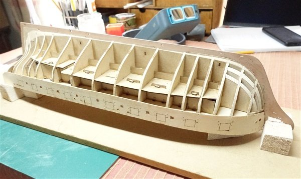
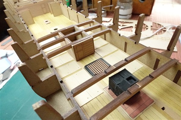
Lower Deck The scuttles are cut from 1mm boxwood using a copy of the deck plan as templates. The centre line is scored and highlighted with pencil. Ring bolts using 2mm Amati and 3mm rings are yet to be added. I added the hatches before planking so some 0.8mm fret was used to maintain their height above the deck. I pondered about the stove hearth: should I place it on top of the planking or plank up to it? I was concerned to maintain the distance between the top of the stove and the gun deck. In the end I decided I would glue the hearth to the sub-deck and plank to it. I found a suitable brick pattern courtesy of Mr Google and printed it off. The hearth is finally edged with 1mm square boxwood. I have marked the position of the stove using a copy of the centre section from the plan. Planking is mostly 3.5 x 0.7mm boxwood. I was surprised by the variation in colour since all the planking comes from the same supplier. The centre section is planked using my latest order but the wider 4.5 and 5mm planks used along the edges of the hatches and scuttles are from a previous batch. Probably not an authentic look but I quite like the added interest and it will not be so obvious in the completed model. Planking the after deck section was straightforward and the block for the capstan is glued in place. The decks easily locate with the frames and the pegs hold them in place. The sail room is complete but awaits hinges and latches from Syren. There are inner wals of mdf and an outer covering of etched pear. The instructions say that the mdf parts are cut so that they can’t be assembled incorrectly – but I know someone who can. 🙄 Once reassembled, I checked it’s position and that the gun deck beams, cabin walls and stove locate properly. Thanks for looking in David


-
Wish I'd thought of that it would have saved a lot of trial and error.
-
A nice tweak Richard. Always tricky to get the shape right but yours looks very good David
-
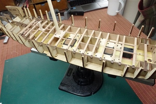
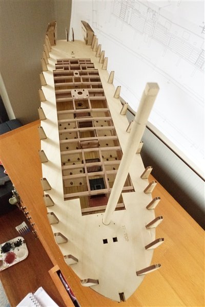
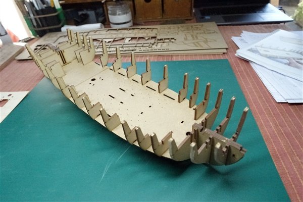
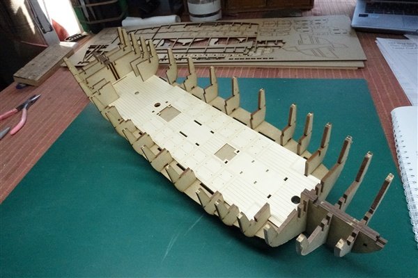
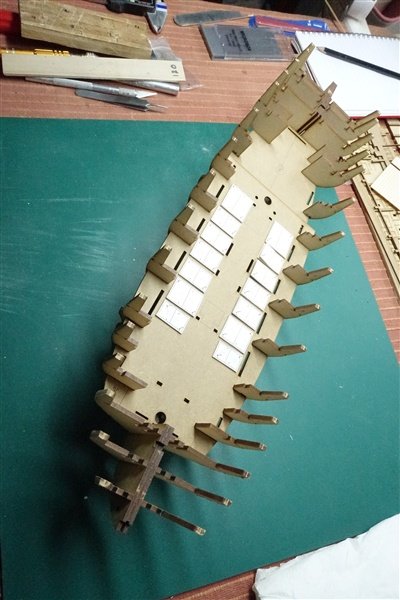
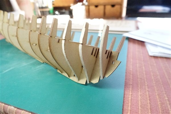
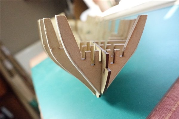
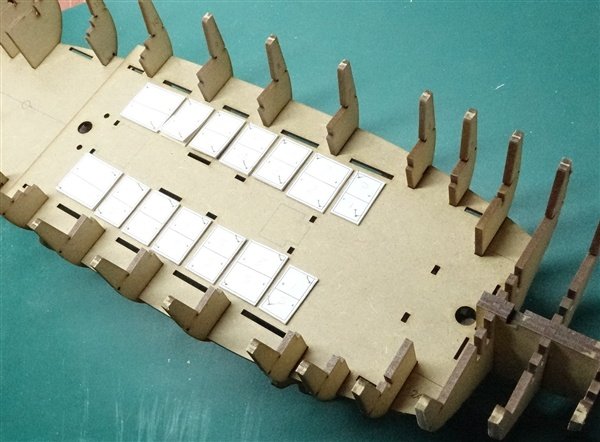
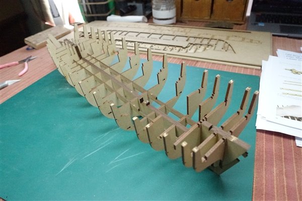
Basic Hull Structure After a three week break Inter-railing through Europe, I can finally start building Harpy. Much has already been said about the contents of the box and the initial build of the basic framework and by far better builders than I. There is nothing for me to add so I will limit my remarks to once more praising the simplicity of this stage of the build thanks to Chris’s innovations, accurate plans and laser cutting. Everything goes together easily without the need to put excess pressure on parts and apart from making the cradle, there is no gluing required until later on in the construction of the basic framework. The first three frames bevelled back nearly to the laser-etched marks, leaving a bit still to play with. I’ve completed the first stages and am now working on the lower deck. I’m following Maurice’s @Blue Ensign lead here and as with my Speedy, will be planking both fore and aft sections as well as later the gun deck with boxwood. Supplies are on order and expected Monday. Until then there is work to be done on the scuttles and the deck structures. The laser etched decks as supplied The scuttles cut out of 1mm boxwood sheet and temporarily pinned to the deck
-
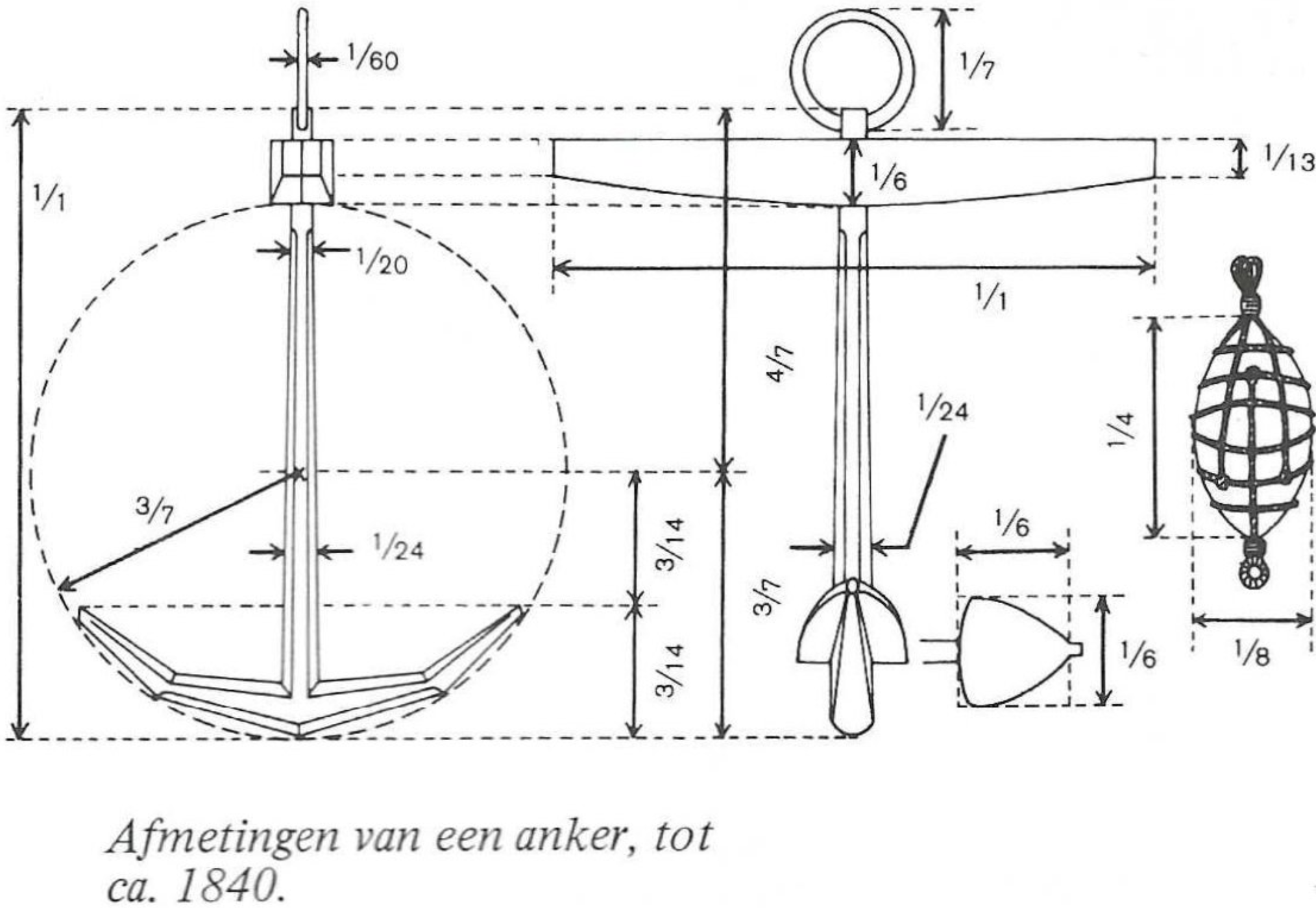
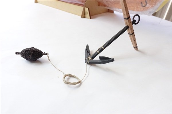
Back in Post#91 I said that I couldn't find information on the size of anchor bouys. Yesterday @En-Dan sent me a message with the following drawing, which I thought would be interesting and useful to others so with his permission, I have copied it below. The drawing is presumably from a Dutch publication but unattributed and from a later period than Speedy but hopefully still relevant. The bouys that I made are 16.4 long by 9mm diameter so pretty good for length against Chris's 60mm anchors but a little wide in the girth. Next time I would use 6mm diameter dowel as the starting point for the same anchors. David

- 114 replies
-
- 3
-

-

-
- Vanguard Models
- Speedy
- (and 1 more)
-
Thanks Ron. Yes it is good to see it completed - there were times when I wondered... Thanks Dan, Glad the log will be of some help. Just take the rigging a step at a time and I'm sure you'll be pleased with the result. David
- 114 replies
-
- 2
-
-
- Vanguard Models
- Speedy
- (and 1 more)
-
Thanks Chris and Thuky David
-
Thanks everyone and thanks Uwe for your very kind words. It will all be worth it in the end. Would love to see some photos of your finished model. David
- 114 replies
-
- 1
-
-
- Vanguard Models
- Speedy
- (and 1 more)
-
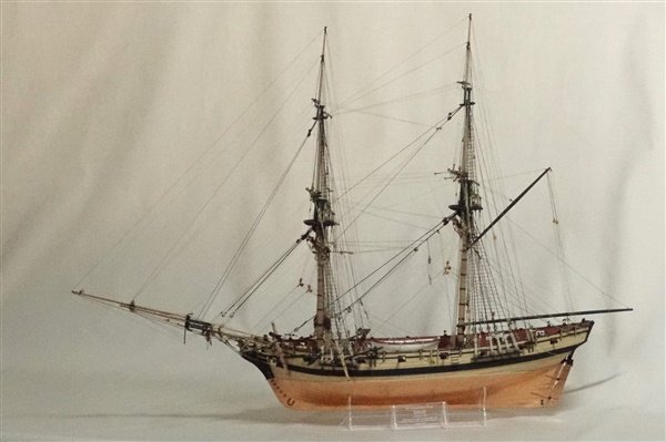
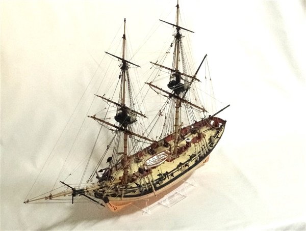
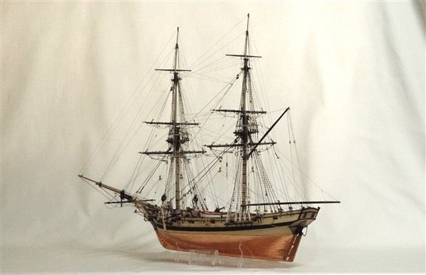
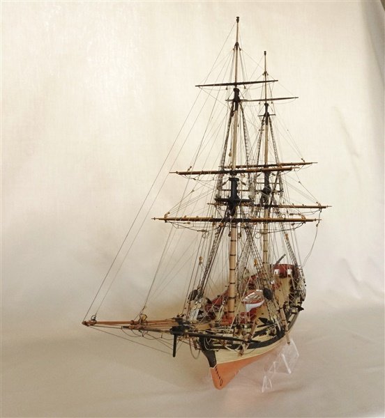
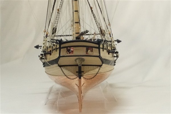
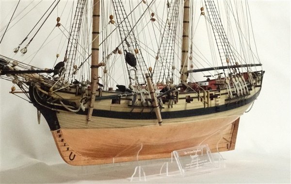
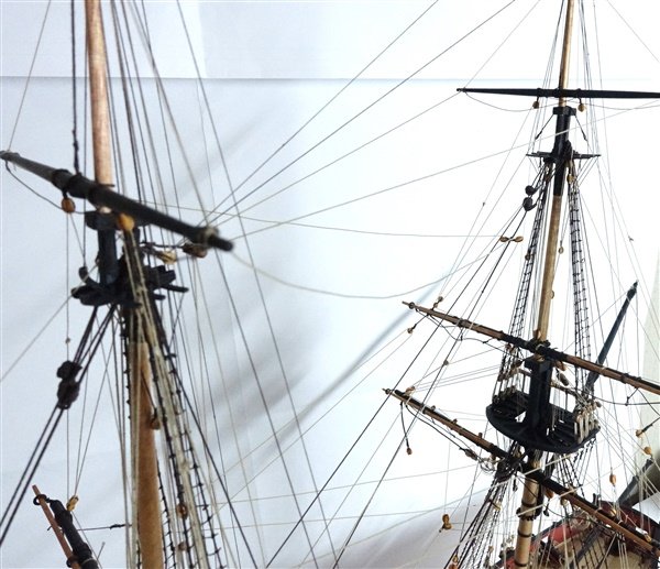
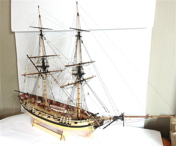
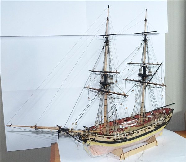
A few shots of Speedy sans ensign but otherwise complete. I did find a mistake in the topmast yard braces which needed correction. There maybe more that I haven't seen but hopefully not. Thanks again to everyone whose followed, liked or commented. David
- 114 replies
-
- 16
-
-

-
- Vanguard Models
- Speedy
- (and 1 more)
-
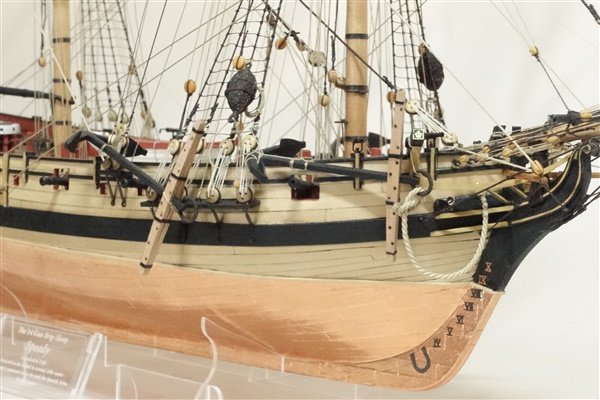
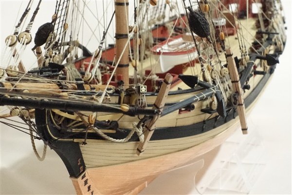
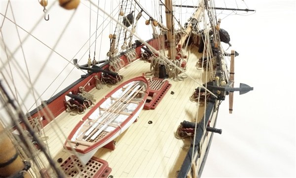
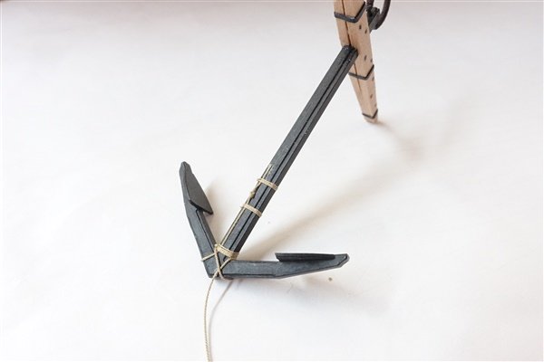
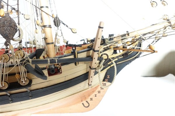
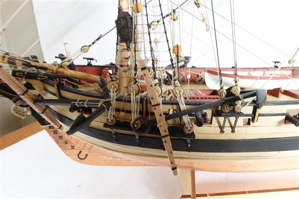
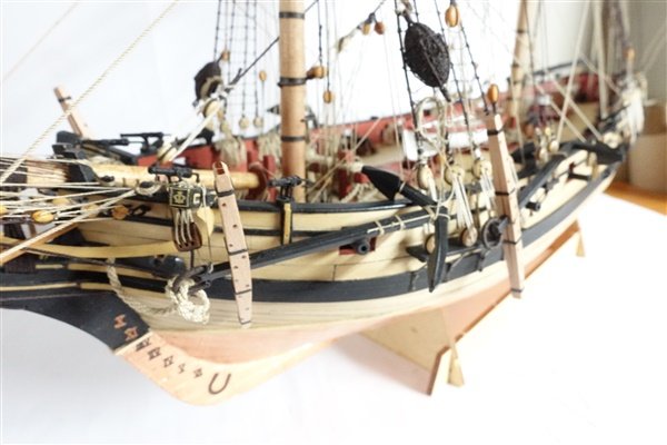
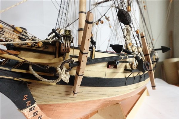
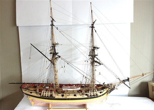
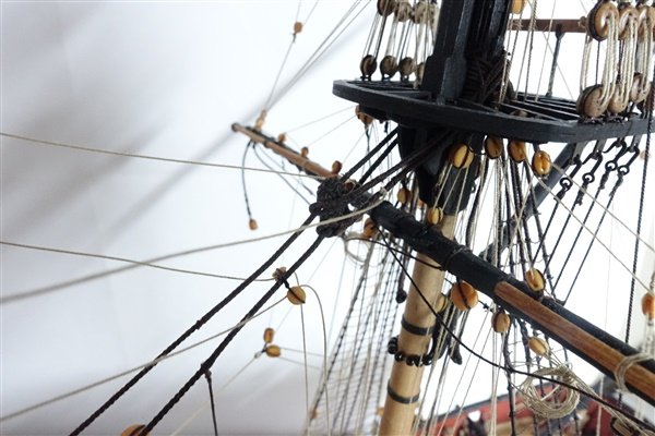
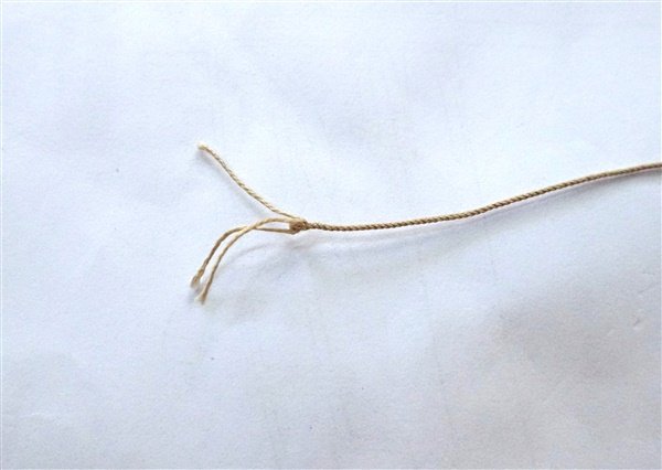
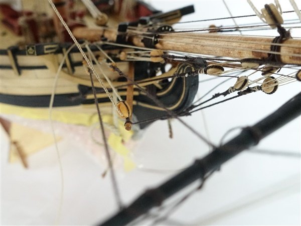
Anchors – The first job is to attached the anchor bouys. I used 0.35mm rope. A knot is tied in the rope and a seizing put on either side around the shank. A third seizing is added at the end of the shank nearest the crown. The rope is wound round the crown and the anchor bouy seized on the other end. The excess rope is coiled and two siezings added to hold the coils in place. The bowers are attached to the cable by a clinch. The cable is taken through the ring from the front, wrapped around itself and secured with three seizings. I decided to show one bower catted and with the stopper in place and the other fully tied in the chains. The other two anchors, spare anchor and sheet anchor, I think they are called, are tied up in the chains. Finally I’ve added the ensign halliard using a 3mm double block at the peak and a single in the stern. This will now have to wait for a slot in my flag painter’s schedule to add the ensign. Other than that everything is there. It only remains to tidy up the horses and lines by wetting them out with very dilute matt varnish and small weights. The build has taken almost a year, a little longer than I expected – but I wasn’t in any hurry. I planked the upper bulwarks and stern in boxwood rather than using the patterns provided and I also planked the deck in boxwood and modified a few bits and pieces along the way. I'll post a few more photos when it's all 'ship-shape' In the meantime, thanks to everyone who has been following and for all the comments, help and encouragement - it has really been appreciated. David

- 114 replies
-
- 13
-
-
- Vanguard Models
- Speedy
- (and 1 more)
-
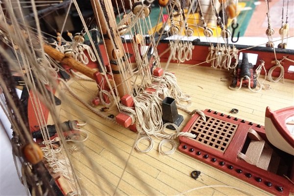
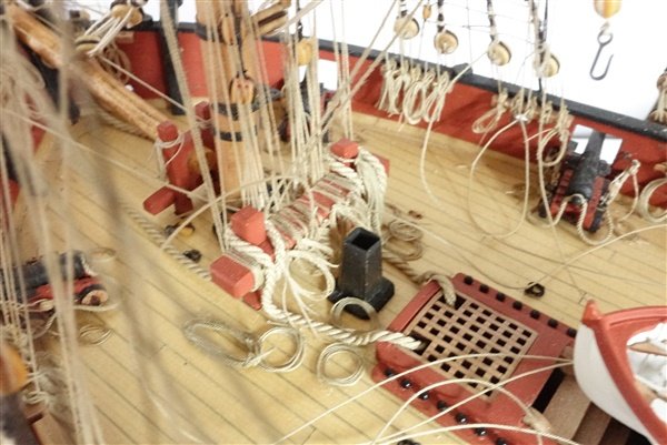
Thanks everyone for the likes and kind comments - much appreciated. Bowlines – This is the first model to which I’ve added bowlines and with all the other lines present it is quite a challenge. On reflection, I wish that I had added them to Diana I used 0.2mm line. Each bowline begins by being tied to the yard with a timberhitch. The foremast bowlines lead down through the blocks on the jib or bowsprit, through the saddle and to the bowsprit step. The main mast bowlines again start from a timberhitch on the yard. The topgallant lines feed through holes in the fore topmast trestle trees, the topmast through the outer blocks on the foremast top and the main course through the blocks at the base of the foremast. All lines are tied off at the forward bitts. To be honest I struggled to get them into their proper place so some lines just run to where I could reach. Maybe, I should have checked how all the ropes ran down to the bitts before starting the rigging, I would also have just trimmed the lines and left off all the hanks and coils until the end. Well that completes the rigging which was by turns challenging and frustrating and the most complicated that I have tackled so far. There’s a lot of rope in a such a confined space. I’m glad that I'm not adding sails and their associated ropes. It's hard to see all the smaller ropes but I'll take some better shots when she's finished. David
- 114 replies
-
- 11
-
-
-
- Vanguard Models
- Speedy
- (and 1 more)
-
Many thanks Maurice that's very kind and encouraging of you to say so. I've been closely following your build of Harpy. There are some great tips and ideas which I would like to try when I start work on it after Speedy David
- 114 replies
-
- 1
-
-
- Vanguard Models
- Speedy
- (and 1 more)
-
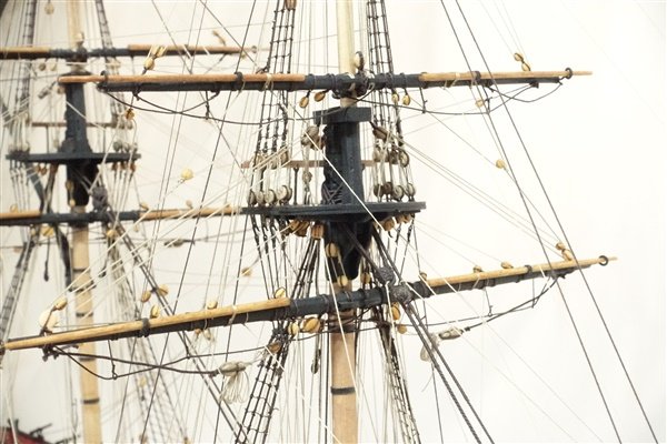
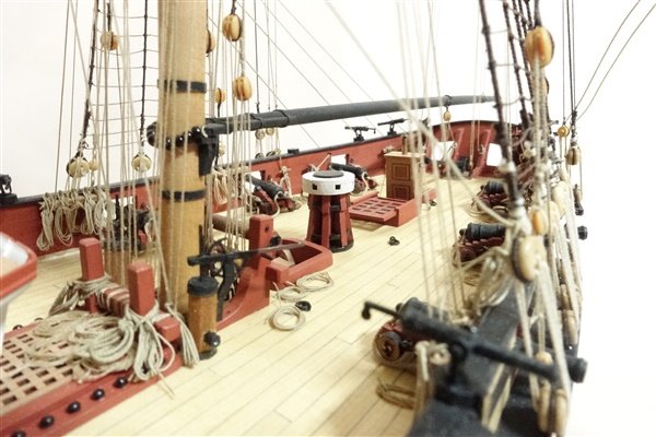
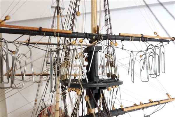
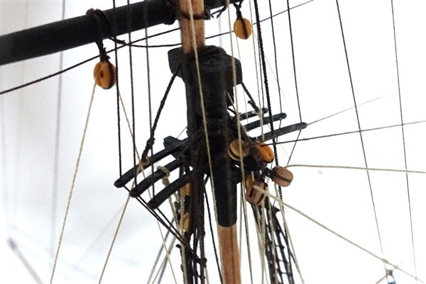
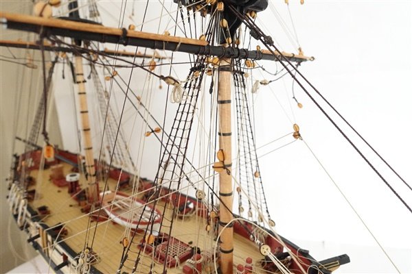
Braces – I am running out of 0.25mm rope from RoS, so I have used 0.35 for the topmast, topgallant and spritsail yard braces. Although oversized with reference to Steel, I think that they look fine. The main issue with the braces was again finding space for the topmast yard braces on the bitts. I count that there are 23 ropes tied off to the forward bitts and 13 at the main bitts. How the crew could find the correct rope in time before incurring the wrath of the officers is a miracle. There was also the difficulty of adding a pair of blocks to the fore topmast head at this late stage to take the main topmast braces. Like Derek, @DelF I resolved the issue by using a single long strop for the two 3mm blocks needed. I have left some slack in the braces which will need some small weights and dilute matt varnish to give the catenation that I’m looking for. The spritsail braces are threaded through the inner sheave of the double blocks under the foretop. I was struggling until I used a fine broach to align fore and aft blocks and then I could slip the end of the stiffened rope through easily I’ve reached the home straight as far as rigging goes with just the bowlines to complete. David

- 114 replies
-
- 11
-
-
- Vanguard Models
- Speedy
- (and 1 more)
-
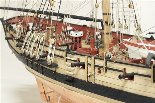
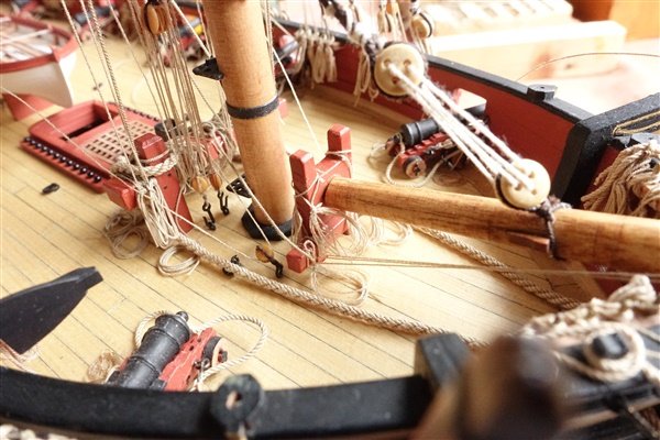
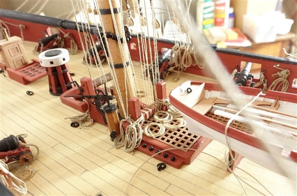
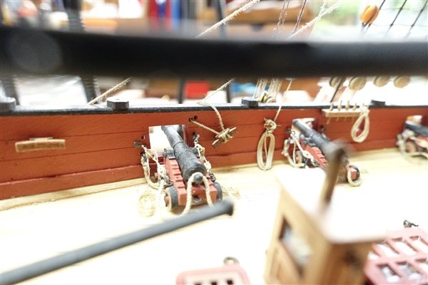
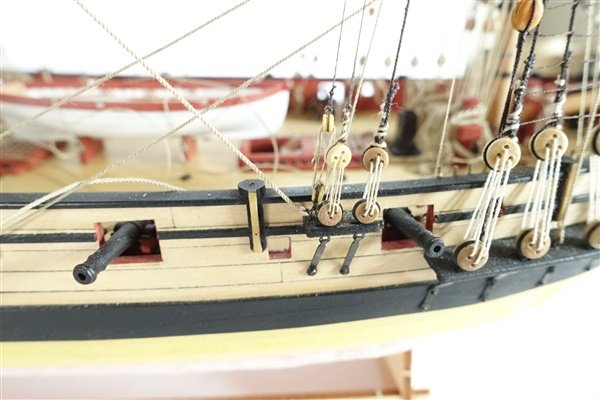
Moving on to the Main and fore course sheets and tacks. Steel says sheets are 3”, Tacks 4” and clews 2” ropes. I have used 0.45, 0.35 and 0.25 respectively as the nearest that I have available. All the 5 mm needed were stropped with a becket the lines prepared and threaded in one go. I tried to make a tack knot rather than use a toggle shown on the plan but couldn’t quite get the interlacing right but have ended up with a reasonable approximation that looks OK to me when rigged. The clew line is tied to the yard with a timber hitch and feeds through the block on the yard down to the already overcrowded bitts. The fore tacks lead through the blocks on the boomkins and are tied off at the knightheads at the bow and the sheets lead aft through the fixed blocks and tie of to the large cleats. The main clews were threaded in a similar way to the fore course. The tacks lead through the fixed blocks just behind the forward stools but there was no provision for the main sheets to tie off. The cleat is shown on the rigging plan but not shown on the drawings of the inner bulwarks nor could I see a slot provided for it in the inner bulwark patterns. However, it was a simple matter to modify a cleat and pin and glue in place just forward of the aftmost 6 pounder. I am now faced with more lines trailing around the ship that need tidying before completing the rigging with the braces and bowlines. Thanks to everyone for the like and for continuing to follow my build. David
- 114 replies
-
- 13
-
-
- Vanguard Models
- Speedy
- (and 1 more)
-
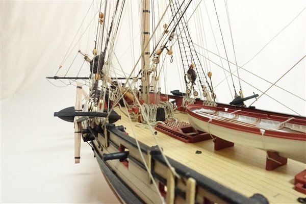
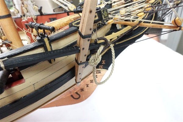
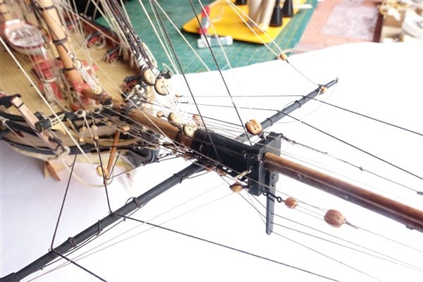
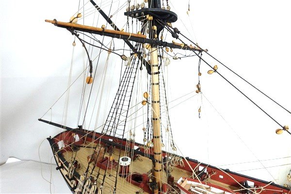
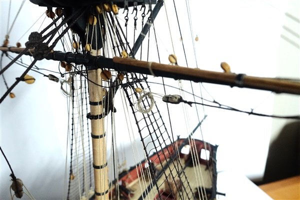
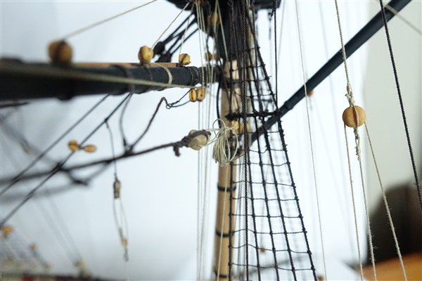
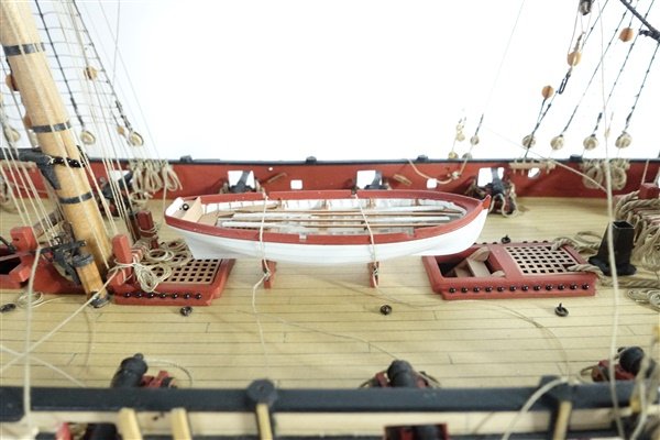
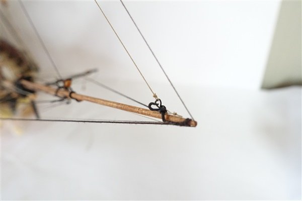
Lees has saved me from the tricing lines. He says that they were usually removed once the tackles were in place – that’s good enough for me. Before access is made even more difficult, I fix the ship’s boat in place. Although I had marked up the cheek blocks on the plans, I had forgotten to add them so had to make them now. I used some 2x2 boxwood reduced to 1.5mm and cut two notches to represent the sheaves. They were painted black before being glued to the topmast heads. The jib and flying jib stays and outhaulers are added, using 0.25mm rope. I think I have attached them to the travellers the opposite way round but I have trimmed them off and now am short of rope to replace them. I hope that no one will notice. Thanks for the comments and likes David
- 114 replies
-
- 10
-
-
- Vanguard Models
- Speedy
- (and 1 more)