HOLIDAY DONATION DRIVE - SUPPORT MSW - DO YOUR PART TO KEEP THIS GREAT FORUM GOING! (Only 24 donations so far out of 49,000 members - C'mon guys!)
×

The Bitter End
-
Posts
279 -
Joined
-
Last visited
Content Type
Profiles
Forums
Gallery
Events
Everything posted by The Bitter End
-
 Thank you very much my good man! I hope I don't disappoint. It has been a great journey so far.
 -
Hello Peter! Thank you very much for this and for your reference to the work of Marquardt. All very interesting and another opportunity to learn. I think I am with you and monsieurs Grok and Marquardt that there were certainly wales comprised of heavy strakes. The question is now becoming more and more, how visible are these wales, somewhere between a totally smooth curve and a total step above and below. From a practical perspective, I would say that there was probably a thickened section with heavy chamfering on the corners to prevent tearout, so essentially a sort of hybrid between a curve and a step. It is so hard to really determine what to follow, in reality when trying to make an approximation of what the vessel really looked like. For one, I wont be painting her, so that is certainly wrong, but the subtleties of the choices made by the ship builders on the day are sadly impossible to know, but make a great opportunity for discussion and interpretation. Cheers! Haiko
- 233 replies
-
- 2
-

-
- Model Shipways
- constitution
- (and 5 more)
-
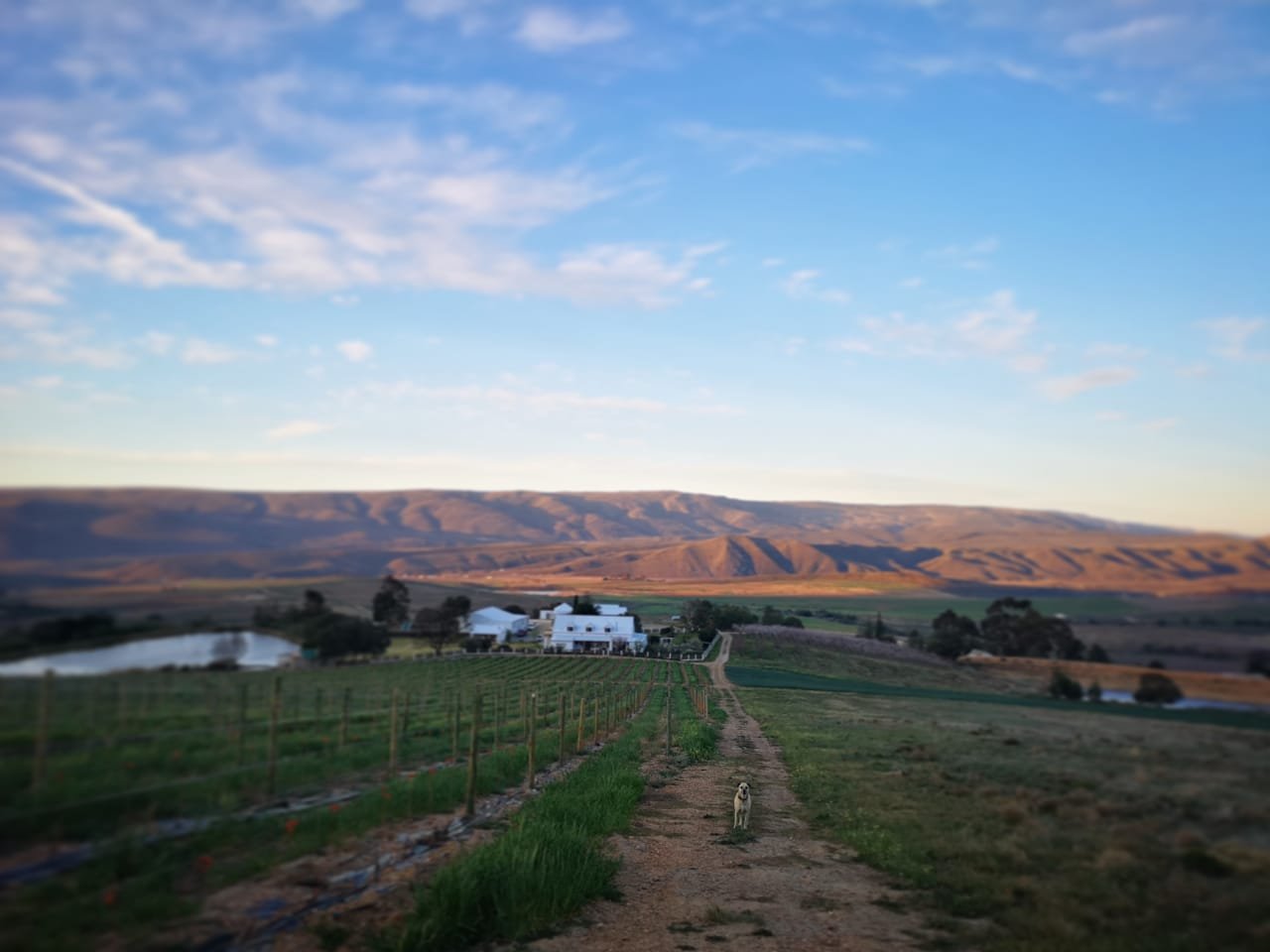
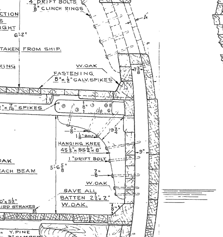
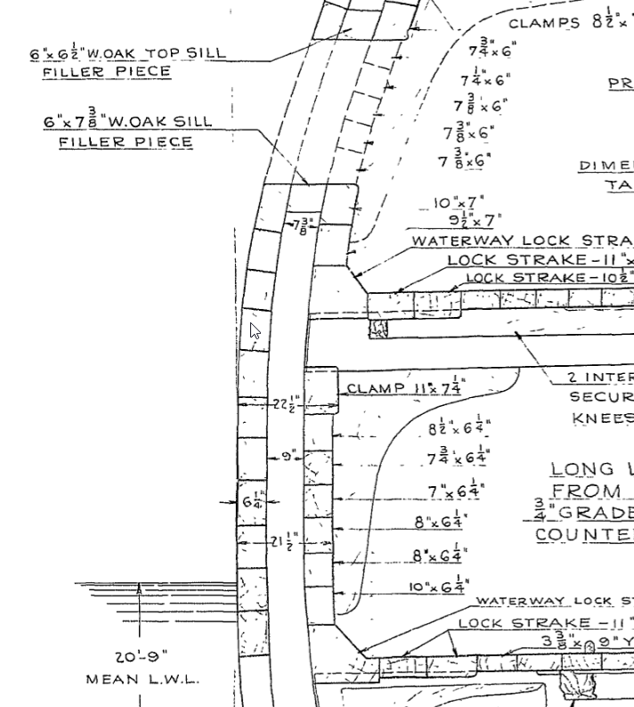
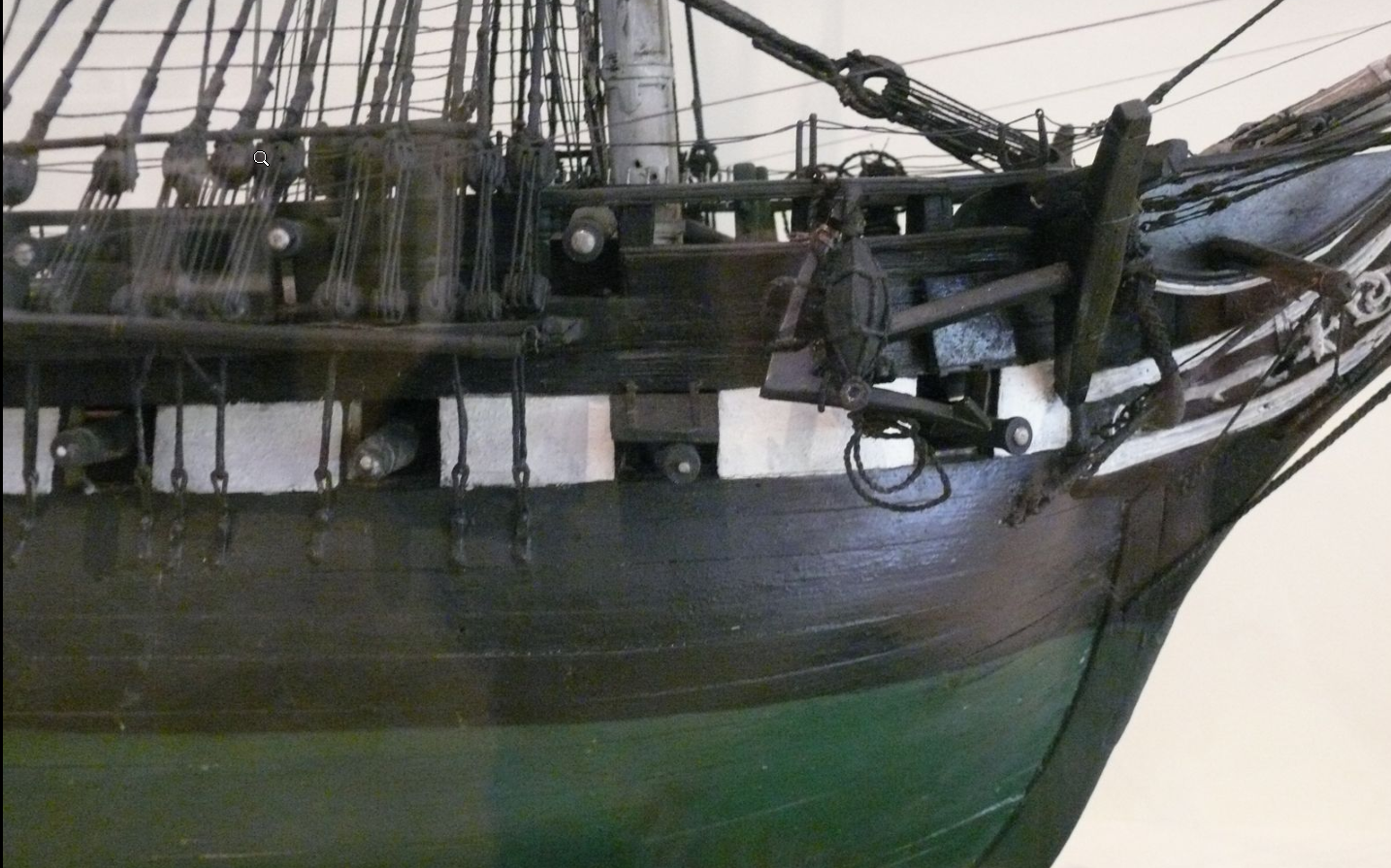
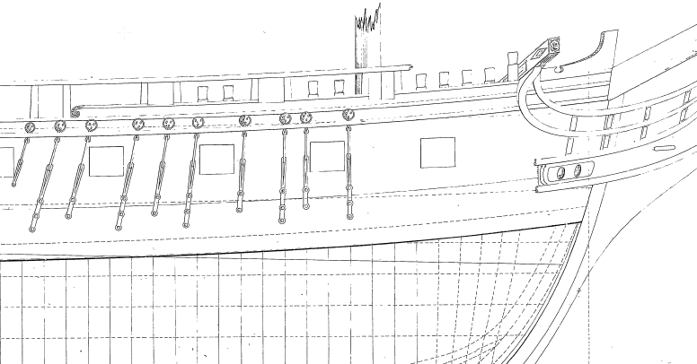
Good evening All After a bit of a break to focus on redoing the farm website as well as the labours of preparing for the summer season I am back at work on the important stuff. I dove right back into planking and quickly ran into some problems and then some more problems. firstly, the wale. In my attempt to pursue historical accuracy I did a little research on what the wale might have appeared like in 1797 and came across the following very confusing information... 1. the 1926 lord cross section drawings: Starboard side(presumably showing what the restorers were meant to built to). Note only one lip on the wale upper edge 2. 1926 Lord cross section, same drawing, Port side, presumably as found?? smooth hull no Step on the wale 3. yet another lord drawing showing an upper and a lower step with a protrusion of 1 to 1.5 inches 4. The hull model from 1812 showing what appears to be a totally smooth hull....this model pays alot of attention to other details so it would surprise me if this feature was there but was not shown in some form. 5. and finally the humphreys plans which appear to show some wort of wale like markings but that is by no means a definite It is of course possible that the wale was there but was just so insignificant in protrusion that it was not shown on any of the paintings or drawings of the ship from the time, while in reality still being there. The fact that Lord included this feature may also simply have been a byproduct of the fact that he simply expected it to be there based on standard practice. I am personally unable to find any feature or piece of text which indicated the stepped wale other than the one version of the Lord drawing. I would love to hear your views and perspectives on this. how should the wale be represented?! Should it be there at all? and if it is, an upper and lower ledge or just the upper. Cheers Haiko
- 233 replies
-
- 2
-
-
- Model Shipways
- constitution
- (and 5 more)
-
Thank you for this, I assumed that this was just a deck planking layout but It seems that it was applied to hull planking too. I am probably going to make use of this plan coupled with the suggestion by Dziadeck below. Thank you to you too, this is a great example of how well all your contributions can help. I have decided to go for roughly a 4 butt shift while simultaneously always erring on the side of longer planks rather than shorter planks where a question comes up about where a joint should land. this is a small detail but the intention is to show that the builders in america at the time would have had access to more abundant timber resources than their european counterparts. I have quickly found that landing on a perfect 4 pattern shift very rarely happens. a plank ending near the bow or stern can easily be extended a few feet or a oint landing too near a gun port can be shifted. quickly leading to a lost 4 butt pattern, in short im using the 4 butt pattern as a guide while working as a ship builder would have...as far as possible. Cheers Haiko
-
Hello Ladies and Gentlemen I am in the process of doing my second planking on my USS Constitution. (see log in signature). I have opted to go with a double planked hull for reasons which currently escape me. I see most modelers allow the joints to fall on the bulkheads provided in the kit but as these have been covered I can have my joints fall wherever is most historically accurate. Does anyone have any sort of idea of how planks were staggered in terms of distances between joints and not just pattern(although I would love a reliable planking pattern too). Dude to the short intervals between the ribs on the actual ship I guess any plan could theoretically have worked but I am really interested in achieving as much accuracy as possible, specifically focusing on how she would have looked when launched in 1797. Any ideas would be very well recieved. Cheers Haiko
-
Beautiful and unique. I wish I could see it in person. Well done!
-
And normally the bottle neck to the results is the ability of the user. So congratulations, good tools or not, you are the one steering the ship. What exact models of lathe and milling attachment do you have? Cheers Haiko
-
Holy smokes I want that lathe.
-
Good morning Daniel, Thanks for your message. I wish I could show you a proper finished product but life has been incredibly busy and I have not had a chance to actually get to the finishing part of any of my build(besides a matte aerosol varnish on the completed stern gallery). That being said I did do some testing and I must say that the finished produced by the osmo poly-x was by far the most beautiful. This was suggested by @Mike YAnd is the result of careful testing which he did, I couldn't be happier with the results. Here is his work https://modelshipworld.com/topic/7297-beavers-prize-1777-by-mike-y-148-pof-hahn-style/?do=findComment&comment=788496 I look forward to seeing what you come up with. Good luck! Haiko
-
What a beautiful shot, you are doing spectacular work. I love the natural wood.
-
It seems the tribe has spoken and everyone agrees you are the man to go to for planking advice. I will take a look through chucks instructions and read your log and see what I can come up with... Also thanks for the advice on ropes, I will be doing some online shopping in the near future. Haiko
- 233 replies
-
- 1
-

-
- Model Shipways
- constitution
- (and 5 more)
-
Thanks Ronald, Exactly what I was looking for. I wasn't aware that the chapters could be downloaded on their website. Cheers, Haiko
- 233 replies
-
- 1
-
-
- Model Shipways
- constitution
- (and 5 more)
-
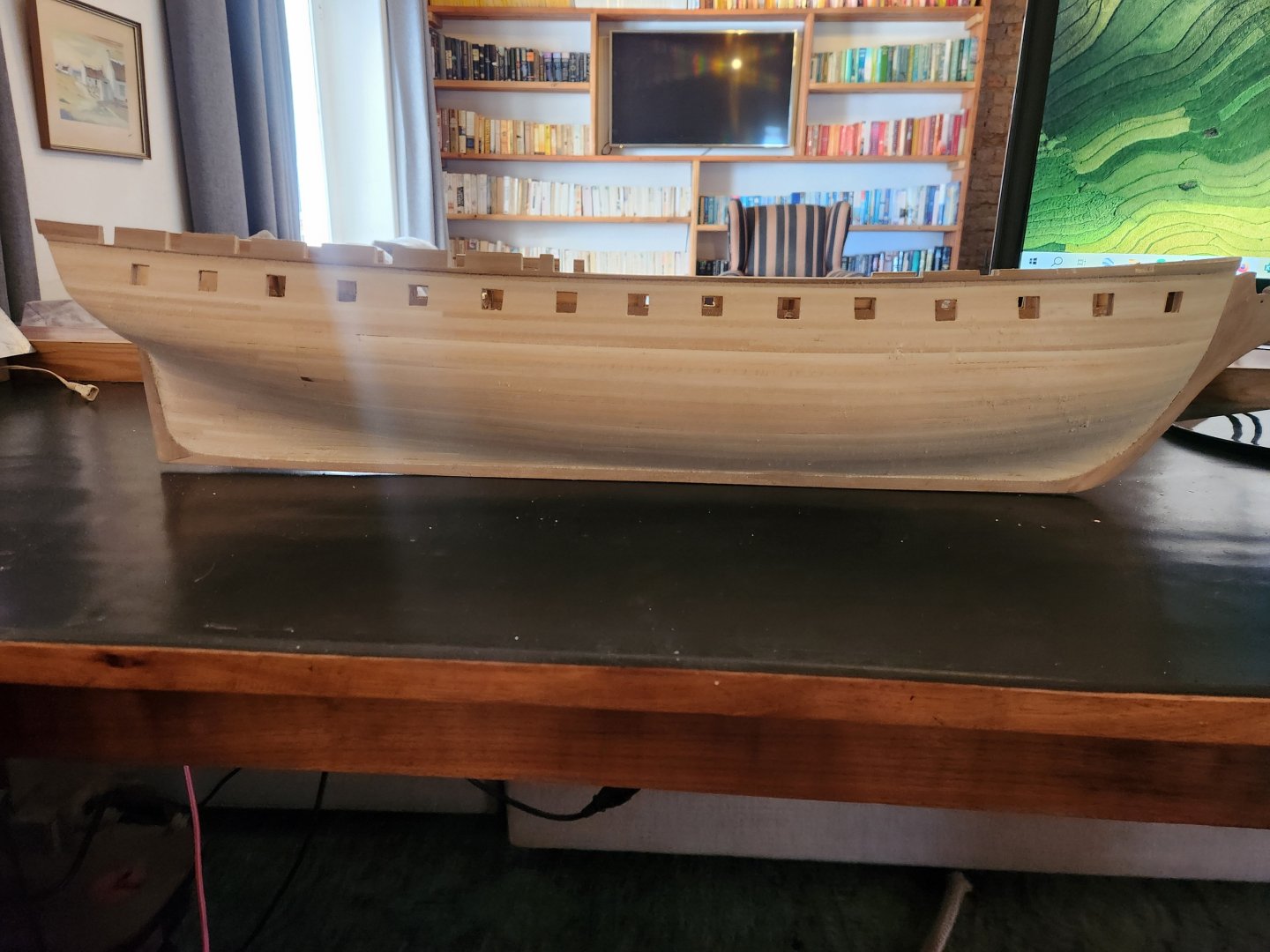
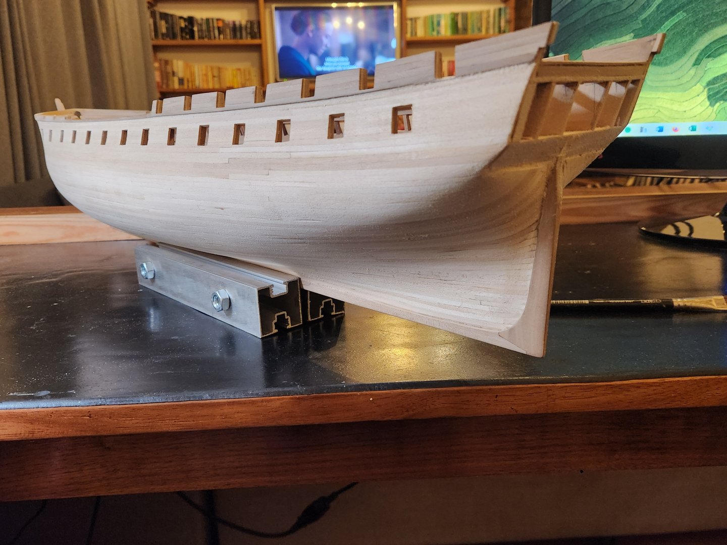
Hello Everyone Not a terribly exciting or in depth post today. Just an update to show the first planking. There is nothing of historical significance here except for the fact that one can now more clearly see the 1707 spacing of the gun ports, which are evenly spaced below the gun ports above and the absence of a bridle port. As some of you may know I am going with a double planking approach, the first layer being done with the supplied timber(fairly nasty stuff) and the second with pear wood(still to be cut from logs which are drying). This approach has 2 main benefits, the first being the creation of a smooth stable shaped hull to secure the pear wood to and the second being an opportunity to learn a bit about planking. This being my second build this was much needed to hone my skills before the final planking. I did the starboard side "correctly" besides the fact that I used single runs of planking as far as possible instead of the correct length planks as in the final layer. I did however attempted to taper the planks correctly etc. This went pretty well on the Starboard side but I somehow messed up the process on the port side and developed a strange curve in the planking. At this point I decided that it didnt make sense to keep torturing myself and completed the final planking with full width planks. My next step is to plank below the stern gallery and then move onto the final hull planking. All this being said...does anyone know where I can find a good complete planking tutorial. I have seen chucks great videos but they begin after the hull has been marked as far as I can tell. T.B.E. 20250718_071315.jpg-autosave.kra

- 233 replies
-
- 7
-
-
- Model Shipways
- constitution
- (and 5 more)
-
Peter my good man, where did you get this rope? i presume the answer is in this log but I am taking the lazy route to get the information. I love the look at this scale. Thanks, Haiko
-
I think you are right about filler and sandpaper being my friend. I look forward to hearing about the new family orchard. I actually learned alot of what I know from the pen state university textbook on fruit farming. Cheers! Haiko
-
Good Morning Peter! Its great to hear from you, and thanks for checking in. I wish that were true but unfortunately my research has had to largely come to a standstill for now. I was hoping for a quiet winter but no such luck, the farm has been incredibly busy and we are planting a new apricot orchard, so there has been far too much to do. I have however made some decent progress on a rough first planking layer to place the final layer over. This gives me a whole lot more respect for your fine planking on your model, even this rough planking has been a real labour intensive challenge...Hopefully I finish up soon and can post something. At least I have been keeping a close eye on your build to get my constitution fix. Your guns are looking spectacular. Cheers Haiko
- 233 replies
-
- 1
-
-
- Model Shipways
- constitution
- (and 5 more)
-
The Margheretta may have been found
The Bitter End replied to trippwj's topic in Nautical/Naval History
Here you go For more than two centuries, stories have circulated along the Washington County coast: that the British burned a captured Revolutionary War schooner in Jonesport’s Sawyer Cove. Some versions were recorded in 19th-century newspapers and George Drisko’s 1904 “Narrative of the Town of Machias.” Others were handed down through families like the Sawyers. In the 1960s, Valdine Atwood and her mother followed those stories to the shoreline. “Dorley Sawyer’s family lived nearby,” said Atwood, now a Machias historian. “And the story passed down was that they saw the Margaretta beached, saw the crew run into the woods, and saw the British come and set it afire.” No wreck was visible on the day of their visit to the shore, but Atwood reached blindly into the mud and pulled up a piece of timber. On their way out, they passed a white cross on the rocks. “They used to do that to mark a shipwreck,” she said. Atwood said she always believed the stories. Now, a multi-year archaeological study strongly supports her instincts and centuries of oral tradition — the wreck of the Margaretta likely lies in Sawyer Cove. The area around Sawyer Cove is now private property, with no public access, but a neighboring landowner permitted the research team to work on-site. “The wreck in Jonesport, we think, is Margaretta,” said archaeologist Arthur Spiess, co-author of a report about the shipwreck that is soon to be released by the Maine Historic Preservation Commission and the Natural Resources Conservation Service. “There’s no evidence against it, and some strong evidence for it.” Spiess and fellow archaeologist Nathaniel King were alerted to the shipwreck in 2021, when Maine Game Warden Joe McBrine — also a local historian — heard reports of “a ship coming up out of the mud.” “At low tide, you could see it,” recalls McBrine. “We measured it, and it was within a couple of feet of what the Margaretta would have been. I thought, ‘Man, this could really be it.’” McBrine already knew the story well. As a member of the Machias Historical Society and a local reenactment group, he’s spent years educating the public about Washington County’s Revolutionary War-era clashes — including what some view as the first naval battle of the American Revolution, the Battle of the Margaretta. That battle began just weeks after Lexington and Concord. On June 2, 1775, three ships sailed into Machias Bay — among them the British schooner HMS Margaretta. Their mission: to trade for lumber, forcibly if necessary, to supply British troops occupying Boston. The residents of Machias had other ideas. They planned to capture the British officers during Sunday services, but when the British escaped to their vessel and sailed for Machias Bay, the Americans gave chase. They met in battle exactly 250 years ago, from June 11 to 12 of 1775. The clash ended with the deaths of three Americans — John McNeil, Robert Avery, and James Coolbroth — and the injury of several others, as well as the mortal wounding of British commander James Moore and the capture of the Margaretta. The Americans soon hid the 50-ton schooner in what is now Marshfield’s Middle River. In 1776, when Machias men judged it safe to move the vessel, they likely reballasted her in Machias — using local ballast stones that now provide one of three key pieces of evidence linking the shipwreck to the Margaretta. “Her ballast was derived from eastern glacial till deposits,” said Spiess, “and that fits with the rumor that it was laid up for a year and refloated.” Spiess believes the ship’s original ballast stones would have come from modern-day Massachusetts, where the vessel was likely built. The wreck’s construction also offers a critical clue. “The way it was built was not ‘Navy fashion,’” said Spiess. “Everything’s a little bit variable. It’s a local job, not a military job, not perfect.” https://i0.wp.com/bdn-data.s3.amazonaws.com/uploads/2025/06/Drs.-Arthur-Spiess-and-Nathaniel-King-600x450.jpg?resize=600%2C450&ssl=1 Researchers think they have found the shipwreck of the Margaretta, a ship that wrecked off Maine during one of the earliest naval conflicts of the Revolutionary War. Credit: Courtesy of Joseph McBrine This fits with British records showing the Margaretta was not purpose-built but a hired vessel — brought into service by Vice Admiral Samuel Graves, then the highest-ranking Royal Navy officer in North America, to serve as tender to his flagship, HMS Preston. The rougher workmanship of the Jonesport wreck also helps rule out another local theory: that the wreck was an 1812-era Revenue Cutter, which would have been built to stricter military standards. To help date the ship, Spiess and his team extracted pencil-sized samples from one of the rib bases — each with 82 growth rings — and sent them to environmental and maritime archaeologist Brita Lorentzen, a specialist in dendrochronology and shipwreck dating. “Dr. Lorentzen is an expert in this field,” said Spiess. “She determined that growth ring 79 near the outer edge formed between 1750 and 1765.” He added, “That means the tree was still alive around that time, which is exactly the right range for a vessel that could have been built five to fifteen years before the Revolutionary War.” Spiess and his colleagues stop short of a definitive identification. “The statistics on this are that that date range, 1750 to 1765, has an 80 percent chance of being correct, and a 20 percent chance of being wrong,” Spiess said. But with no contradictory evidence and several key alignments, Spiess said the case is “very strong.” But why did the Margaretta end up in Sawyer Cove? According to McBrine’s research, after the Americans repurposed the Margaretta, they used it to pursue British forces and privateers in Machias Bay and the Bay of Fundy. Possibly seeking revenge for the capture of five fishing boats, they set out to pursue the British vessel, HMS Viper. “When they rounded Mount Desert Island, they saw a British ship on the horizon,” said McBrine. “As they got closer, they realized it was bigger than they thought. They turned back toward Machias but couldn’t outrun her. So they went right to the head of Sawyer Cove.” And the rest is history. Before releasing the report to the public, the research team — Spiess, King, J.N. Leith Smith, Lorentzen and McBrine — is waiting to learn whether the U.S. Naval History and Heritage Command will assert a legal claim. “I think this research is important to the entire region,” said McBrine. “To be able to piece together the puzzle — and have experts say this is likely the Margaretta — it adds to our understanding. And it brings a little more respect to the people who were willing to stand up, fight, be wounded and even die to capture her.” Spiess, McBrine and other Revolutionary War history enthusiasts and reenactors will attend the 250th Margaretta Days Celebration, June 20-21, at West Branch Farms Event Center in Machias. -
Thank you to everyone for their kind comments, It makes all the hard work worth it to see it appreciated by people who really understand the challenges. As a side note, What Marcus shared about the window colour and the East India Marine Hall, is a great example of just how many facets there were to this investigation and how many things we looked at and discussed. In fact i completely forgot to mention that we also looked at the color shown in the quarter galleries in the 1803 painting by Corne. This was in fact the final colour used to colour match the stern windows. Cheers! TBE

- 233 replies
-
- 1
-
-
- Model Shipways
- constitution
- (and 5 more)
-
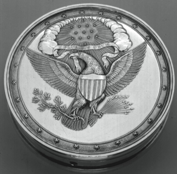
Good Afternoon everyone After quite a long break from this build log it is finally time for an update. This is going to be a long one for a number of reasons so please be patient. Hopefully there is something in here for everyone. I left my last post with the intention of planking the hull but I somehow got sidetracked by possibly this biggest challenge of this build…the stern. As I am sure you all know by now, my intention is to try and build this vessel as she was when she was originally launched in 1797. Little did I know just how impossible this task would be. What you will see below is a combination of compromises, guesses and historical accuracy which I hope does a fair job of representing the spirit of how she would have appeared on the date of her launch. I cannot stress enough just how much of a role @Marcus.K. has played in this process. Without his patience and inuput(thousands of texts and over 600 shared images on whatsapp) this stern would have looked very very different. Many hours of discussion in the early hours of the morning before we went to work or Saturday afternoons while we had some time to relax have completely changed the way in which I see this project, the ship and Marcus himself. Many times we have come to a decision only to realise our mistakes and start again. I think we both learned a great deal during this project and I look forward to working with him until she is ready for launch and beyond. I have gained an enormous amount from my time shared with Marcus, but by far my greatest reward has been his friendship. Thank you Marcus One final note before I begin. This stern changed many times during this process. I will not include all of the failed attempts and as far as possible only show the “final version” of each step. There may be subtle or obvious changes between versions but the 3 images below are the very final permutation. There are several sources which we used for reference including eyewitness description, the writing of Tyrone G. Martin, general information about the styles and attitudes at the time and several artworks. That being said our main sources were the 1804 painting by Michele Felice Corne depicting the constitution at the bombardment of Tripoli and the so called Isaac Hull model which was built by sailors sometime near the period of the great chase in 1812 and presented as a gift to Captain Hull. Neither of these is a flawless source for a number of reasons and therefore required a large amount of interpretation. The painting by Corne is both somewhat unclear and borders on propaganda in many ways and is clearly riddled with inaccuracy. The hull model in the other hand was built several years after ger launch by sailors who had limitations of their own as well as time constraints to complete the model. There is however truth in both and teasing this from the sources was a big art of the journey. One other simple yet notable source was the only real description of how the stern was meant to appear: “The Secretary of War, James McHenry, proposed that the sterns of all six original frigates "should be all alike to shew they belong to one family and represented by an Eagle in the Center with the Constellations around him, suported on each Quarter by the figures of Liberty and Justice." [Brewington, M. V. Shipcarvers of North America. New York: Dover Publications” As mentioned before this is simply one interpretation which should hopefully show the elements of the constitution stern at the time which are most important. I look forward to all input on what might have been done differently but I hope that all can see the method to our madness. Below is a numbered reference image(in a rather strange order) which I will use to summarise the build and decision making process 1: Overall shape of stern 2: Lady Justice 3: Decorative arch 4: Great crest of the United states 5 “Real” windows 6: Lady Liberty 7: Quarter gallery decoration 8: Window decoration painted 9: Name “CONSTITUTION” 10: Window Decoration Carved 11: False Window 12: Hause Hole and wreath 13: Painted banner 1: Overall shape of stern This was determined by simply comparing the shapes of the stern on the hull model and corne painting. Then the images were mirrored and overlayed they produced a surprisingly similar outline. I began by tracing this outline and creating a template which I glued to a 6mm plank of pear wood. Once this was cut out I then repeated the process for the second layer of the stern. And finally planked over all of this with a layer of pear wood. Hause holes were then marked and drilled out. There is a certain belief that these hause holes may not have been open but it is clear that these served an important function and were almost always shown as open in contemporary models of other vessels. The final step was to steam and bend the whole assembly to produce the gentle curve the stern has. Once this basic shape had been made I added the uprights between the windows. I got this spacing from the ratios on the hull model 5: “Real” windows The decision to make this a 6 window configuration was due to the clear 6 window setup in the corne painting and the hull model. There is also a reference as follows: “8 Oct 1812 -- Five "drops" (carvings) replaced between stern windows. [Navy Agent Amos Binney Summary Statement (with enclosures), 1- 31 Oct 1812, RG217, 4th Auditor's Accounts, Alphabetical Series, Box 39, DNA.]” This clearly shows that there were 6 windows in the stern at least around 1812. The 6 real pains of glass as opposed to the possible 4 shown in the hull model was a choice made mostly due to the representation in the corne painting and the known style of the time. The first order of business was to frame the outside of the windows and then install the internal frames. This was done with lime wood, a decision I deeply regret, it resulted in a very fluffy finish which was hard to fix. I allowed the wood to protrude to the back of the transom and be sanded flush later. It can also be seen in this photo that I sanded a taper below the windows and added a rough trim below the edge. Determining the colour of the window frames was a difficult process. I originally painted them white but found the result to be too stark and the white paint too unforgiving I then settled on a dark red brown with some red highlights to create depth. It is also almost impossible to see but I installed a clear plastic sheet behind the windows to represent glass. An effect far more visible in real life. 10: Window Decoration Carved Decisions on how exactly to execute these decorations were difficult, there is very little visible info on this, We ultimately decided to follow the general style of the time more than something specific. The outer drops were made by rolling out milliput on a layer of wax paper, I then cloated the milliput in a thin layer of olive oil and made a small punch using a folded section of soft drink can. This I then used to punch out leaves. Once these had dried I glued them down onto a sheet of wax paper with superglue into the desired shape and sanded then entire decoration flat and thinner before placing it on the stern(the image below shows the decoration before sanding). The center window drops were made by making a slight modification to a image found by Marcus which is period appropriate. (number 6) This was the result of the modification for the 5 drops: These were then printed at the correct scale, glued to a piece of pear wood and carved These vertical wreaths were painted yellow and flanked by window trim 7: Quarter gallery decoration The quarter galley decorations were done in much the same way as the outer window decorations. In this case however some additional milliput elements were added to fill out to space, some simple balls to represent fruit and some other minor embellishments. 3: Decorative arch This arch was another situation where information was very scarce, the corne painting appears to show some sort of lighter embellishment. The hull model shows this as a blank space. The first step was to bend 2 thin pieces of pear wood. I found this was best achieved by first using CA glue to secure one end of the arch and then applying wood glue and clamping the arch in place. This was then filled with a decoration created by cutting up various leftover pieces of brass etched parts from my Pegasus and flooding them with silver solder to connect them and build up 3 dimensional structure as shown in X.kens build log. https://modelshipworld.com/topic/11935-uss-constitution-by-xken-model-shipways-scale-1768/page/11/#findComment-410386 4: Great crest of the United states and 13: Painted banner This particular element took a vast amount of research to nail down. I believe one can safely assume that the eagle appeared on the stern and one would hope it would be in this location. There is a reference to constellations requiring their appearance on the stern and I beliebe I see something like clouds on the hull stern and possibly even in the corne painting. The great seal of the united states appeared as follows from 1782: It officially evolved to a seal looking like this in 1825: I realised that my date isn’t quite right but I like to think that this evolution was a gradual one and an eagle similar to this may have been carved onto the stern. There are numerous eagles of this style which can be found at the time. Below a great example: One interesting quirk of the eagle of the constitution on the hull model is that it appears to be facing “sinister” (viewer right) the normal convention for the seal is for the eagle to be facing “dexter” viewer left. The eagle represented is somewhat unclear and it is possible that the item which appears to me to be the head and neck may well be the scroll it carries but who knows! The eagle does however face sinister from at least 1908 on the restored constitution so I went with this design. Above the eagle I placed clouds carved from pear wood and a sphere above the eagle showing the 13 stars representing the 13 states. A little titbit of information is that there were already 17 states at this stage but that is neither here nor there. On the corne painting it appears that there is some white in the area of the eagle, this could well be the banner the eagle holds. This also presented one of 2 opportunities to show that the decoration on the stern may well have been at least partially painted. I opted to paint this banner using white paint with a small amount of red to indicate the text, followed by a light brushing of yellow to blend the colour into the rest of the stern. 2: Lady Justice and 6: Lady Liberty These elements were copied from baroque style art for their basic shape and carved in pear. Lady justice holds a sword and mirrored shield with a mask below her feet. Lady liberty holds a chalice feeding the eagle(another possible motivation for the sinister facing eagle) and she has a sword below her feet. These ladies were painted yellow as with the rest of the elements but the shield was given a light white coat to show the mirrored shield. Once all these parts had been glued to the transom with a combination of wood glue and CA glue the whole was spraypainted black using rustoleum matt black primer 9: Name “CONSTITUTION” The name of the ship was apparently painted on the stern. There is limited evidence to work from so I simply copied a popular style from the time. This was a pretty laborious process but it was made easier by printing the name at the correct size and then taping it just above the place where the name should go. This allowed me to copy eat letter directly in its correct position. The font I used is called Castellar with a single space between letters. Its not perfect but good enough at a distance. 8: Window decoration painted This little element isn’t too exciting, it was just another opportunity to show that the decoration of the stern may well have been a hybrid carving and painting scenario. These are meant to represent small “bows” used to tie the decorations to the arch close to the top of the window. 12: Hause Holes and wreath The Hause holes were surrounded by wreaths made with the same technique as the outer window decorations. Their position was a subject of some debate and I moved them 3 times. Ultimately their final location was the result of a combination of practical considerations, historical evidence and aesthetics. Final position on the vessel: The final placement of the stern on the vessel was determined by looking at corne, hull and some other contemporary models. This placement requited the removal of a small amount of the bulwark and removing the stern planking which was then glued directly to the transom to allow for the curvature of the stern. At a later date the taffrail will be installed, but that is a project for another day. I think this post has only touched the surface of what was done on this portion of the build. If anyone would like more information about something specific or more detail on how the various parts were made please feel free to ask. As always any comments or criticism is most welcome. Kind regards T.B.E.


- 233 replies
-
- 16
-
-

-
- Model Shipways
- constitution
- (and 5 more)
-
Would photos of the plans help at all? I am happy to try and take a few and send your way
-
I couldn't ignore this observation. Some heavy sanding has leveled things out quite a bit and I'm hoping the planking will. Solve the rest. I can't stress enough how much I appreciate the feedback. This is how one avoids looking at a model with 500 hours in it and realising you made a silly mistake at hour 20 Thanks Peter Haiko

- 233 replies
-
- 5
-
-
- Model Shipways
- constitution
- (and 5 more)
-
Peter my good man! Firstly, thank you and secondly I think you are both observant and correct. The way in which I sanded these seem to have resulted in the concave appearance that you are seeing. I am hoping that I can eliminate this with the 2 layers of planking I must still add over them. I must actually take a look at the Lord drawings and see what exactly the profile should be but it's definitely not like that. I hope this can all be ironed out Cheers Haiko
-
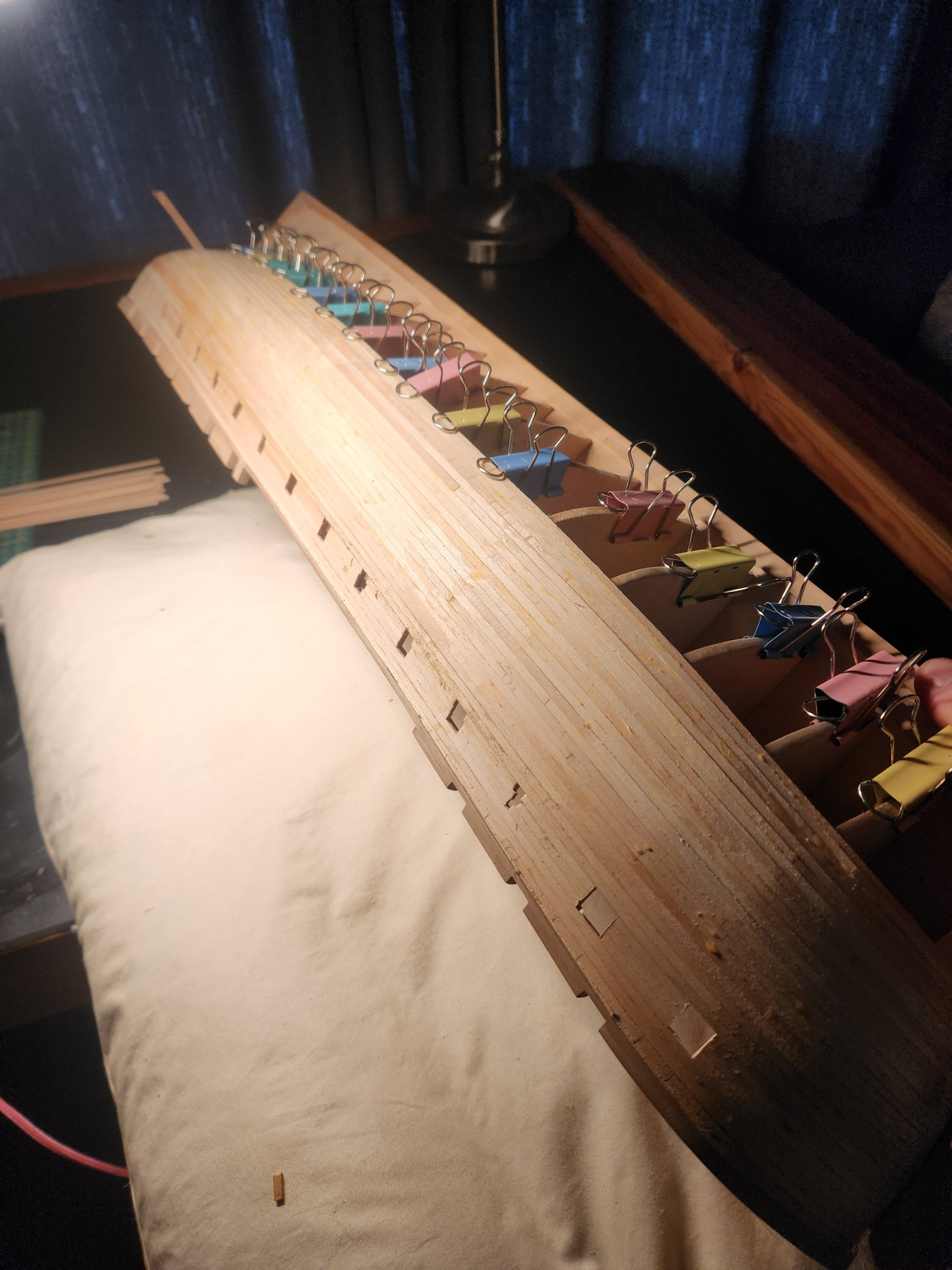
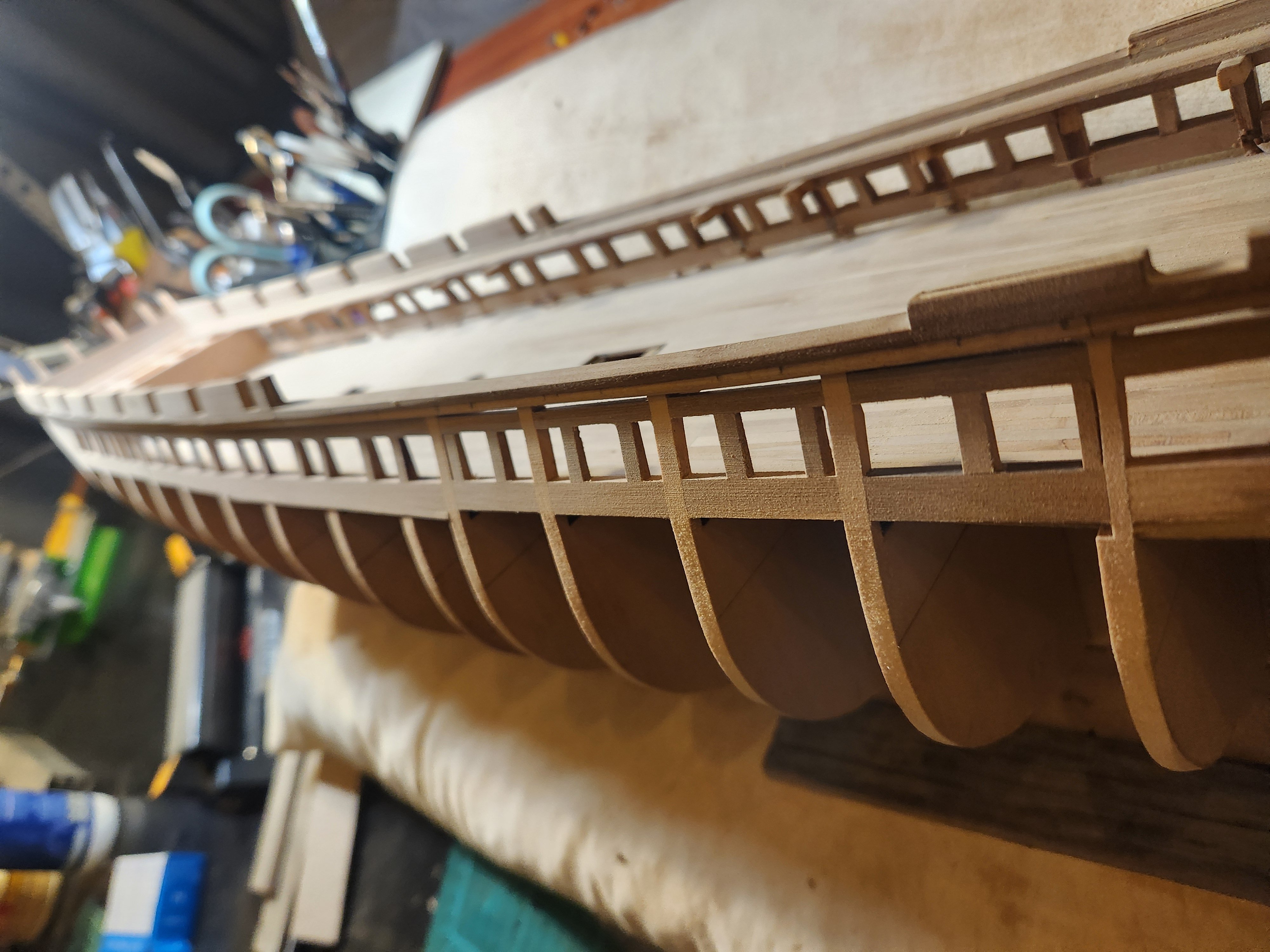
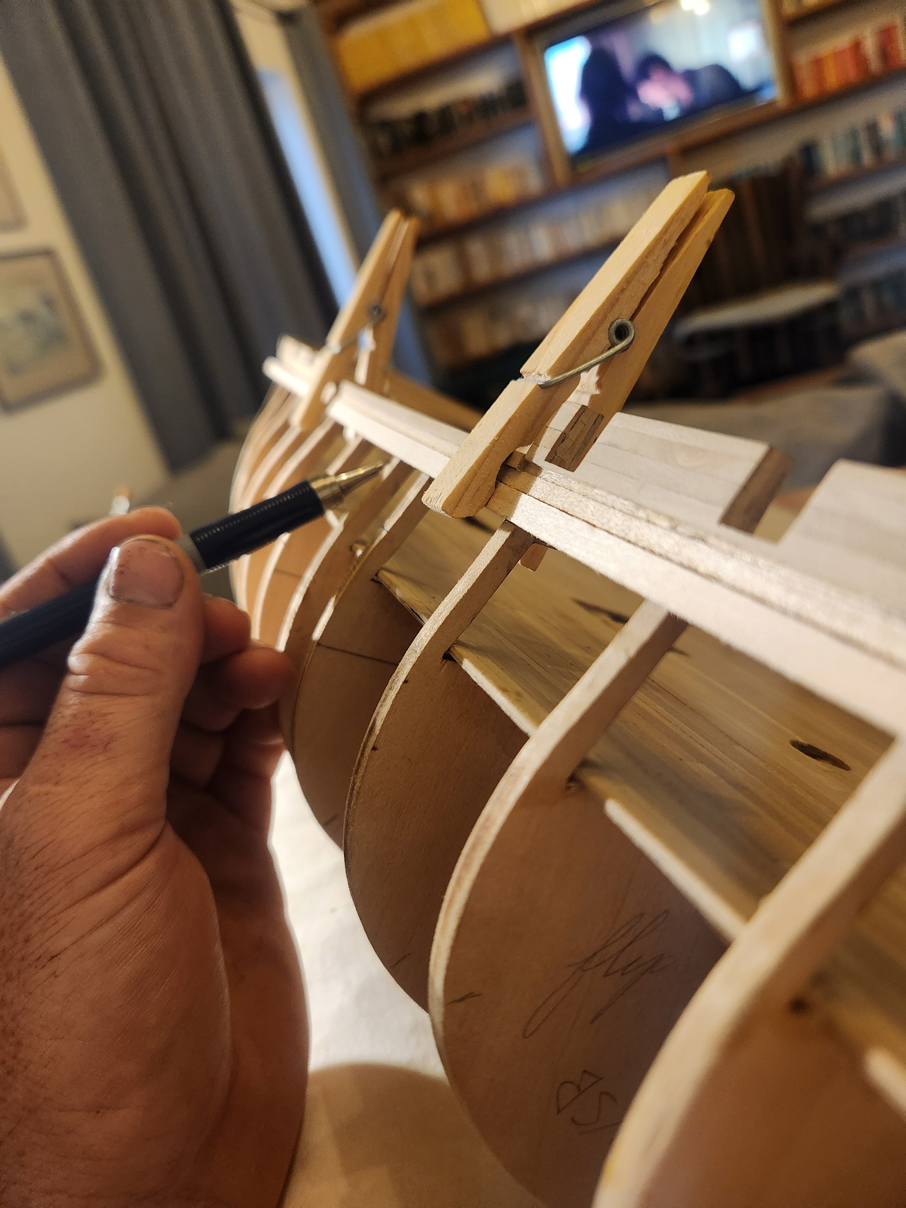
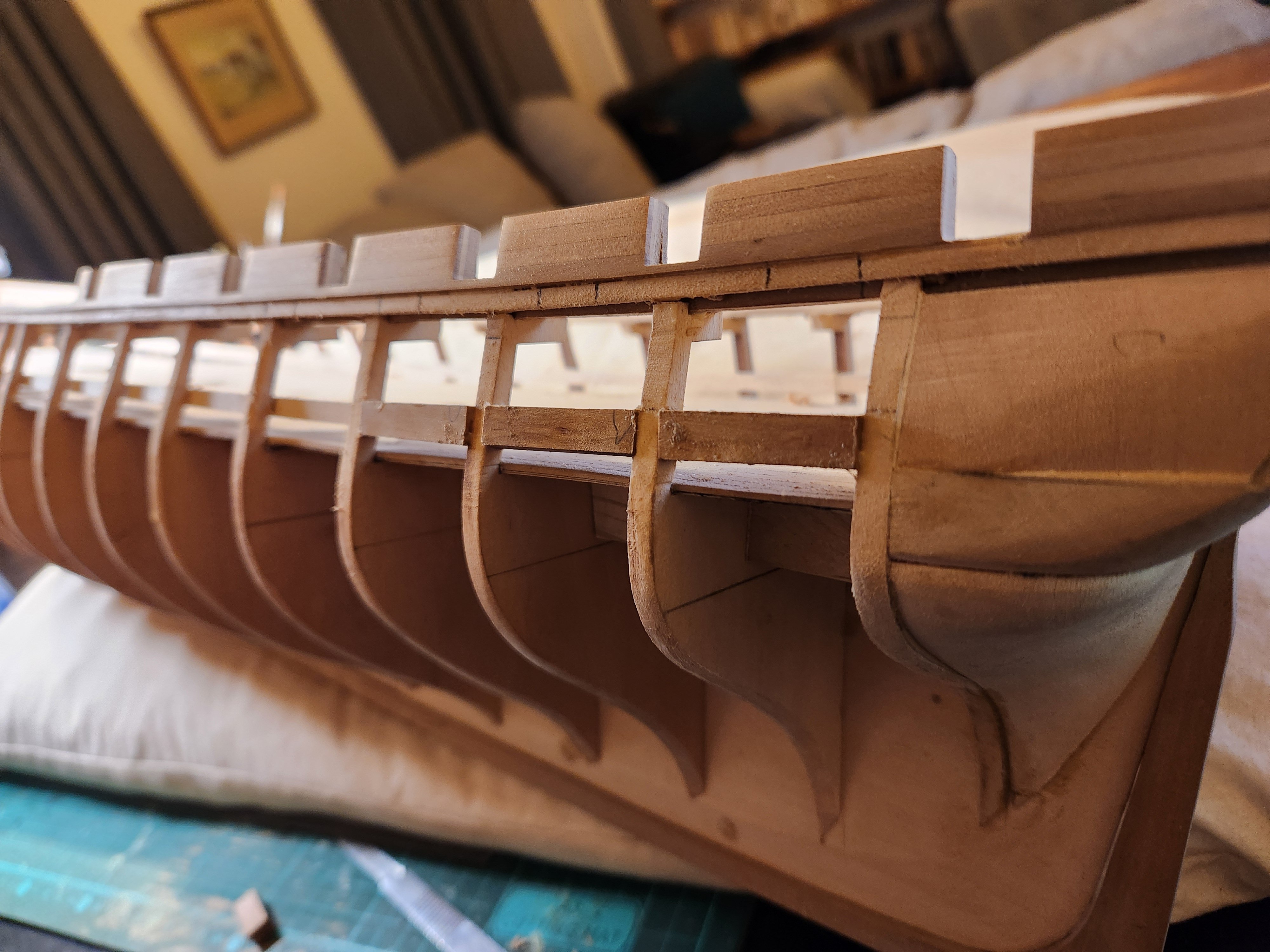
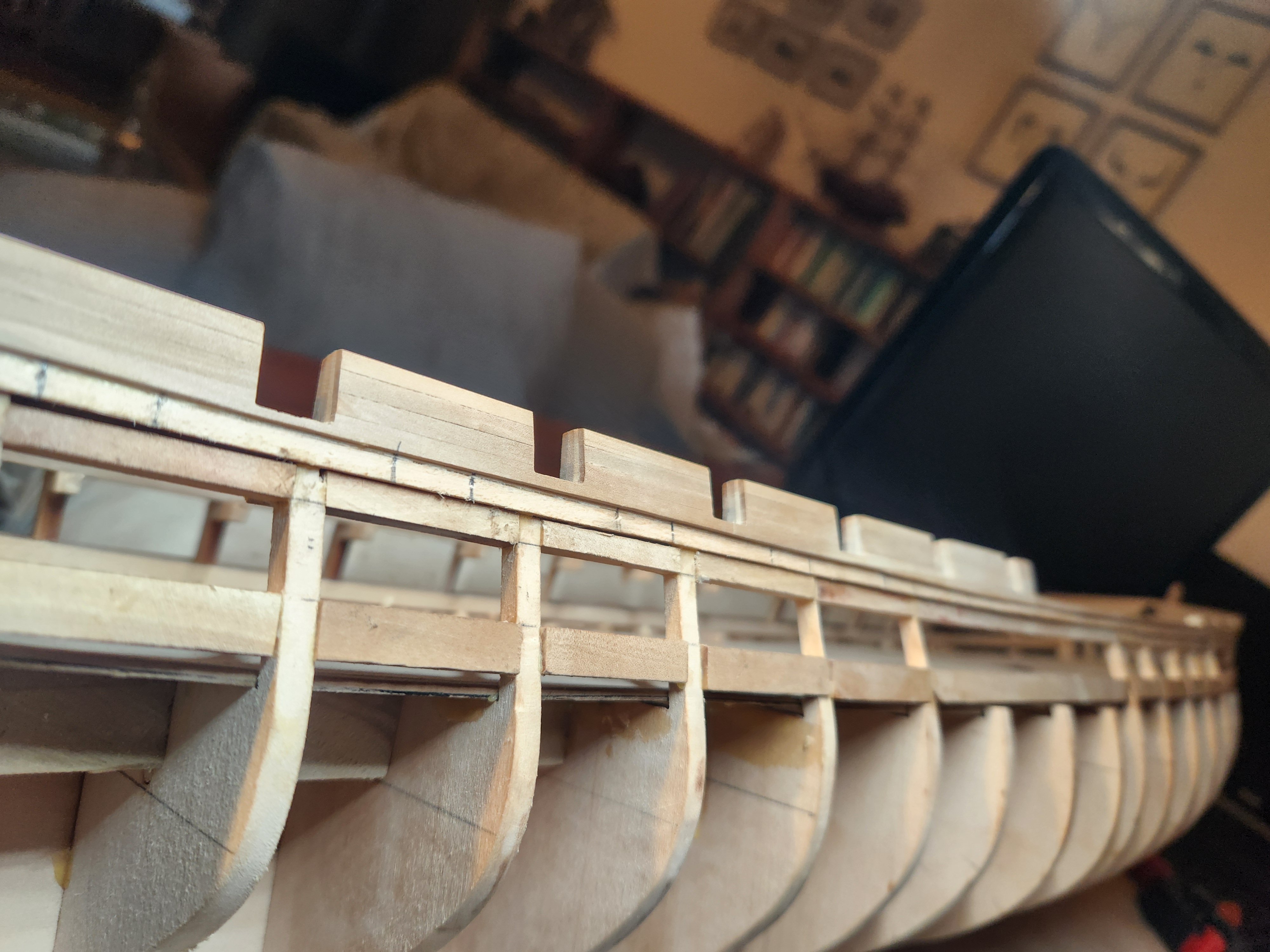
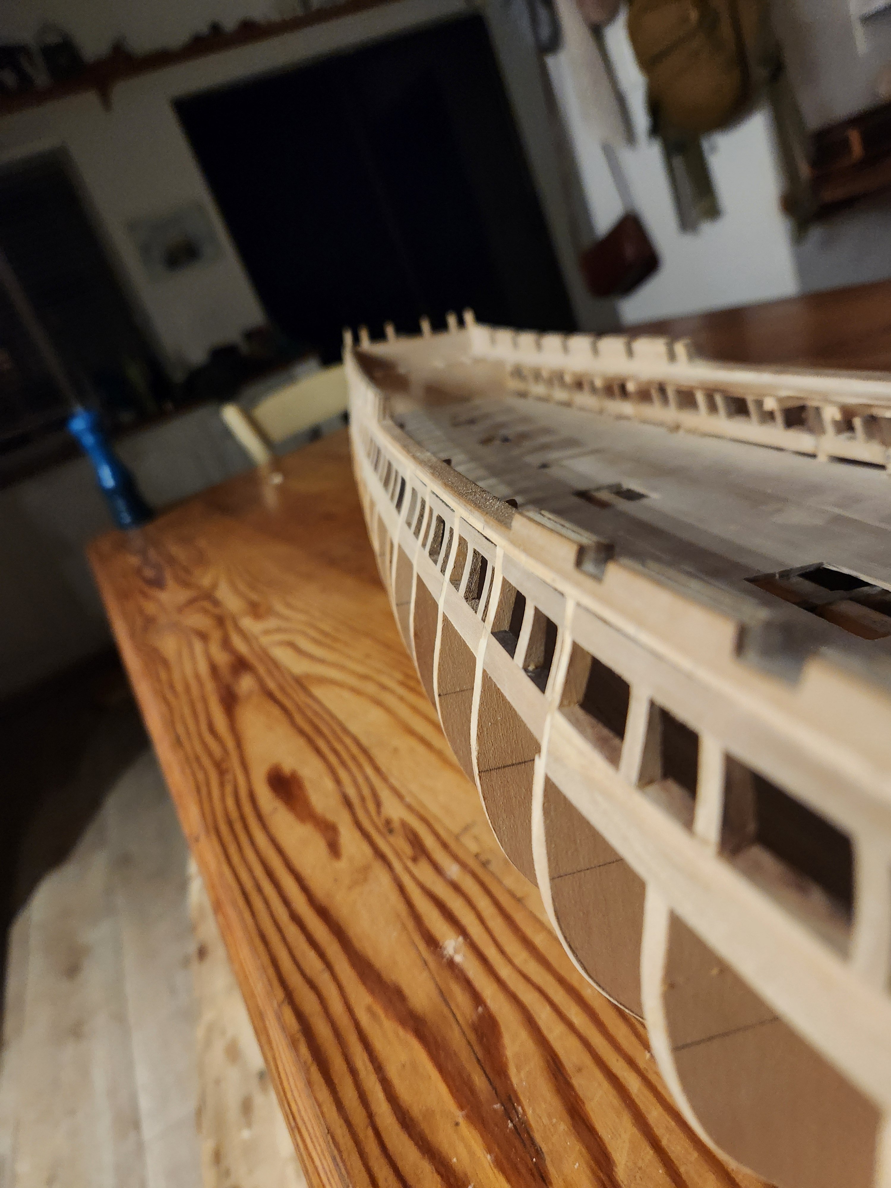
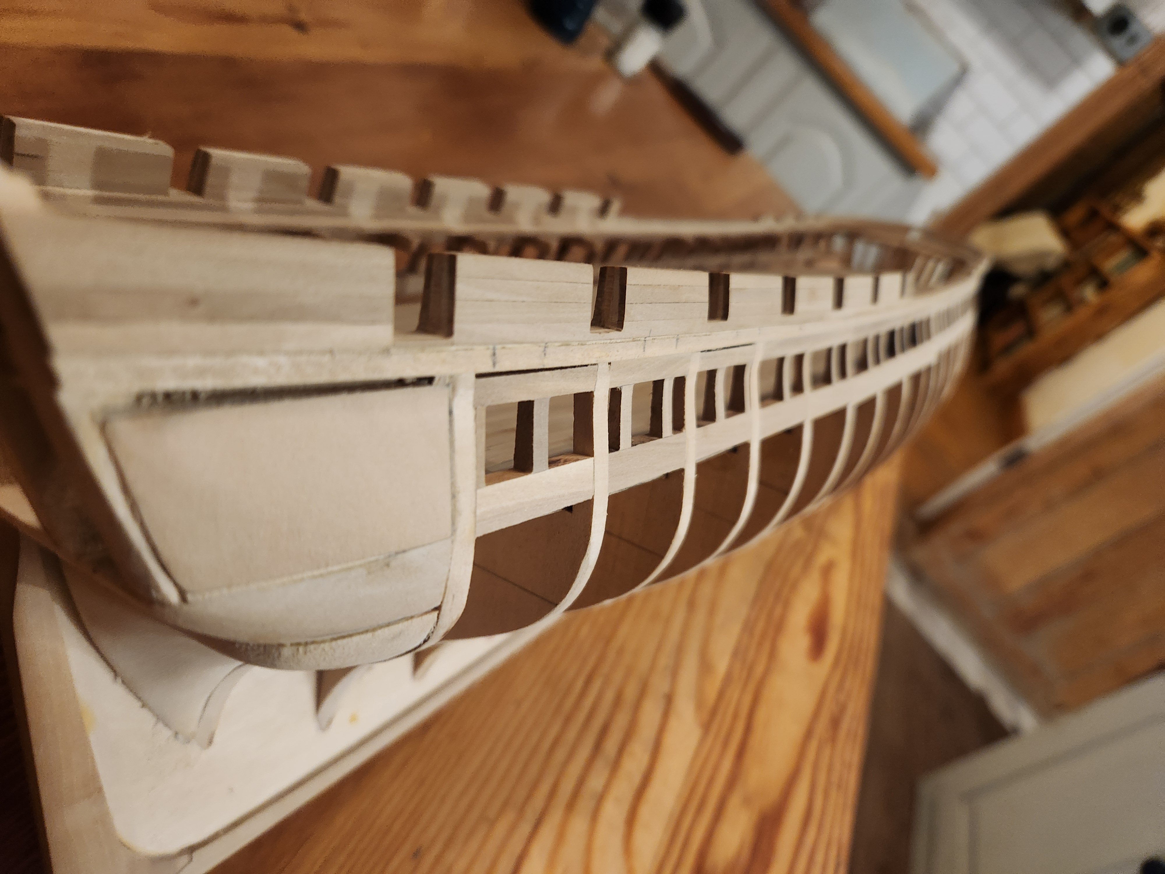
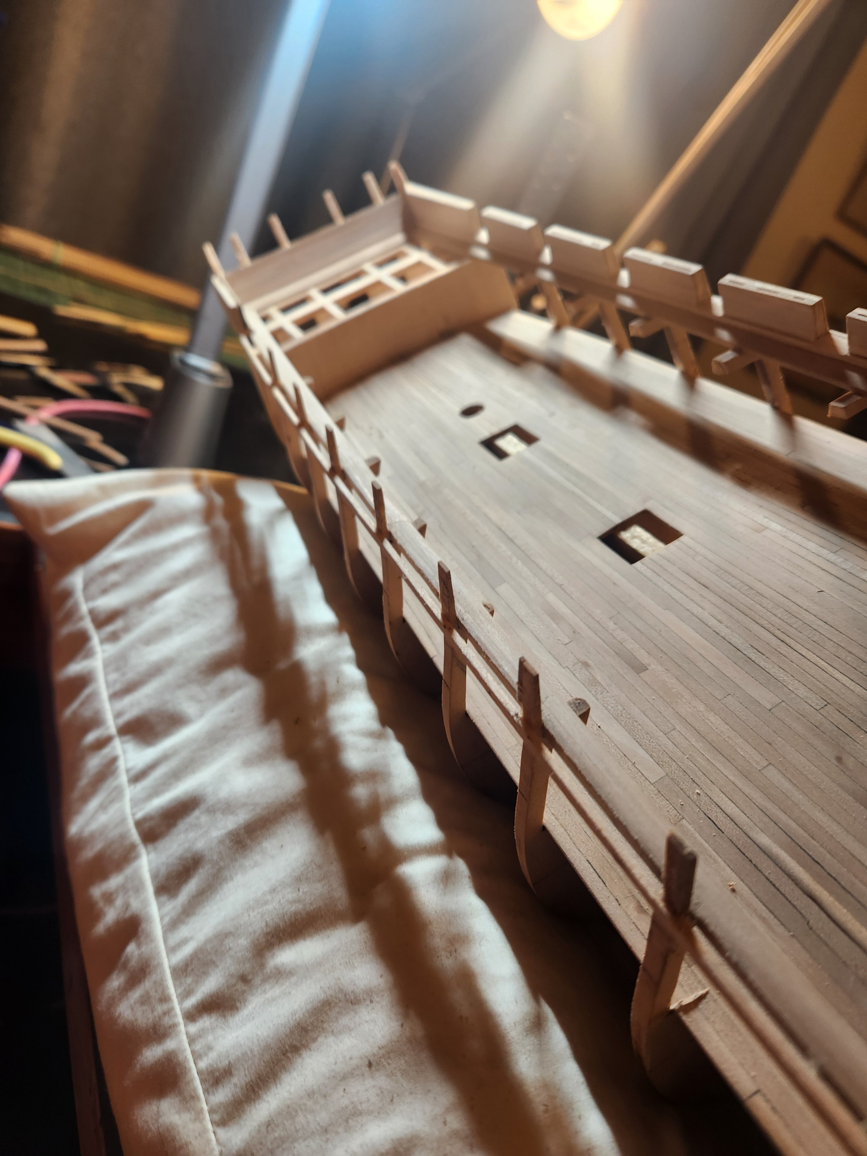
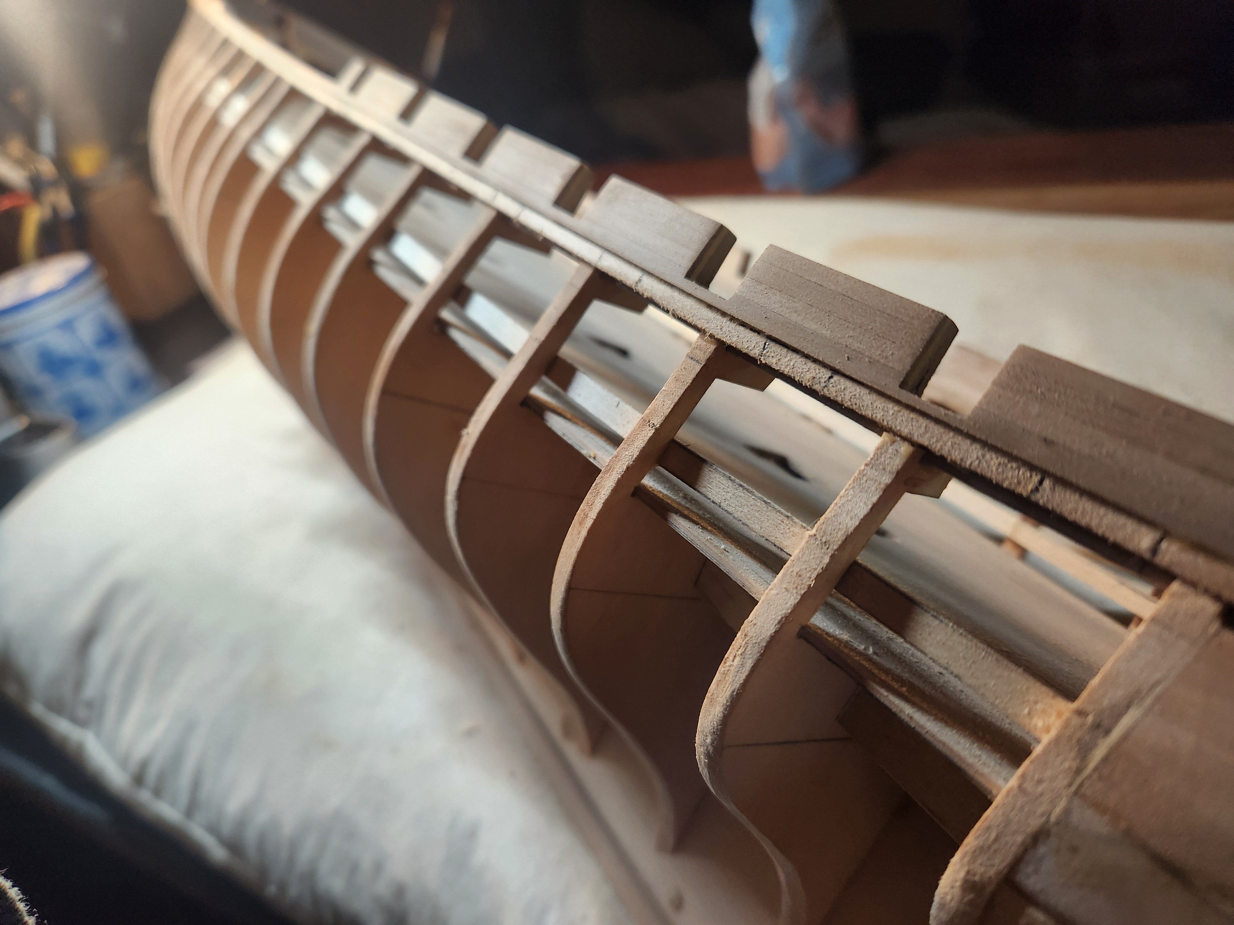
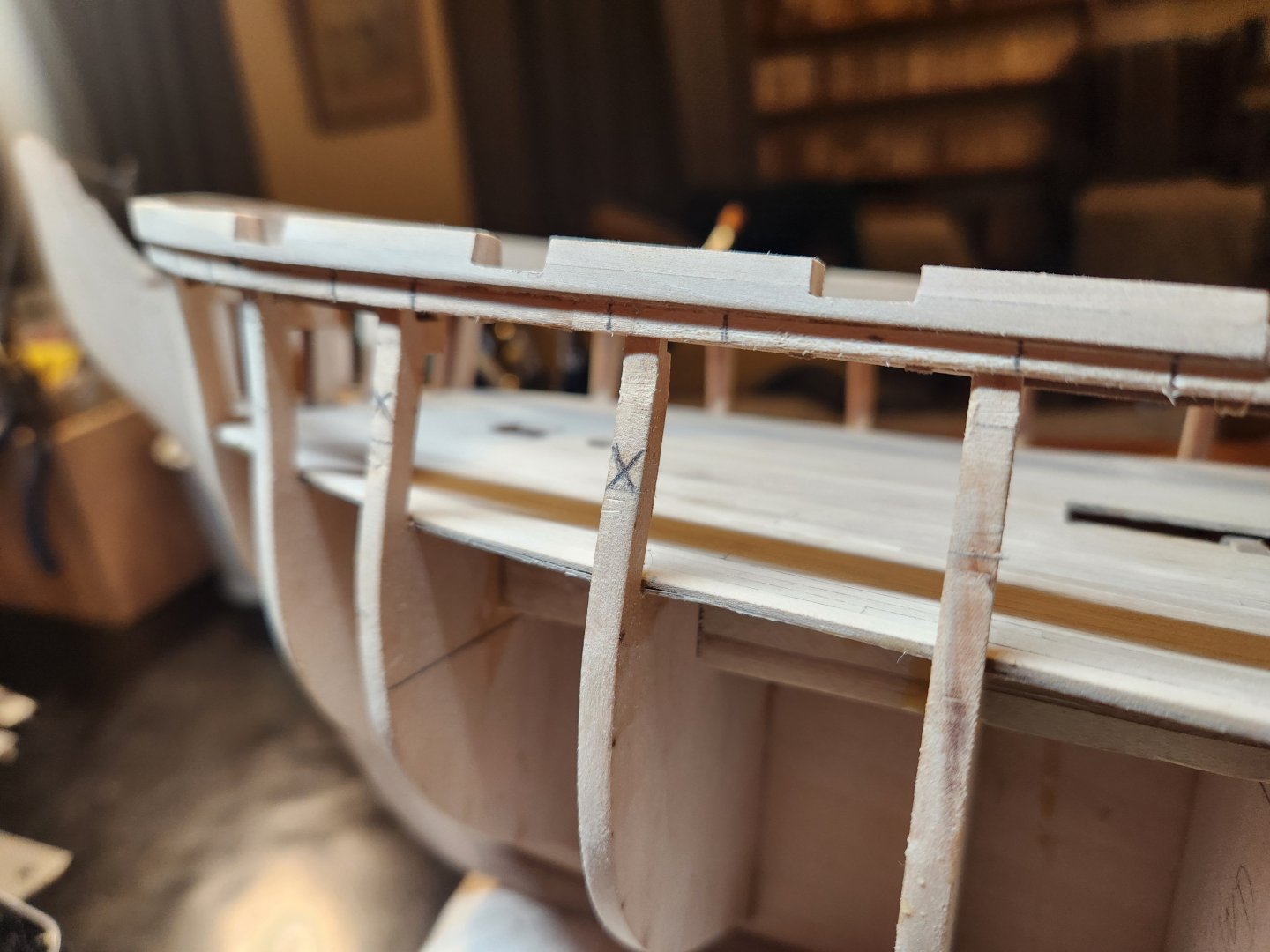
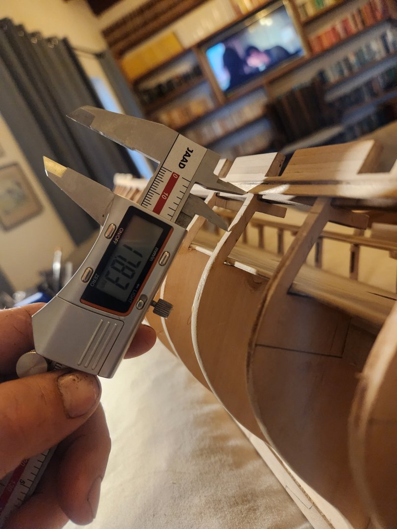
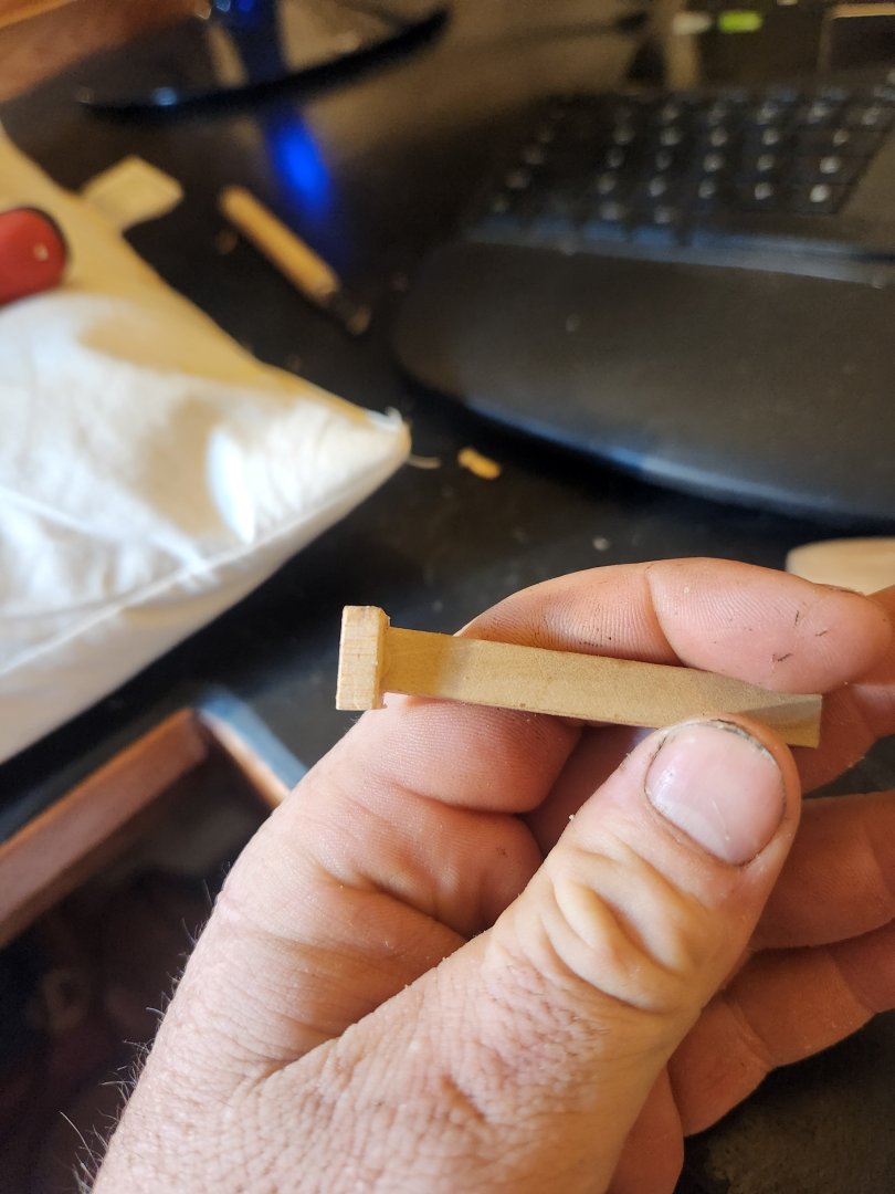
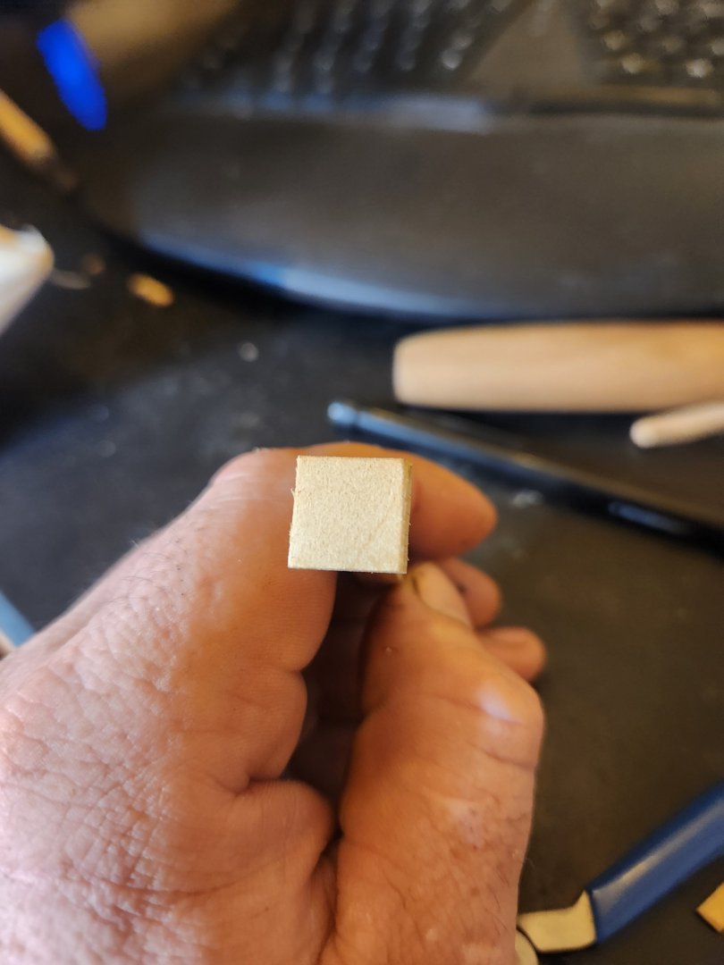
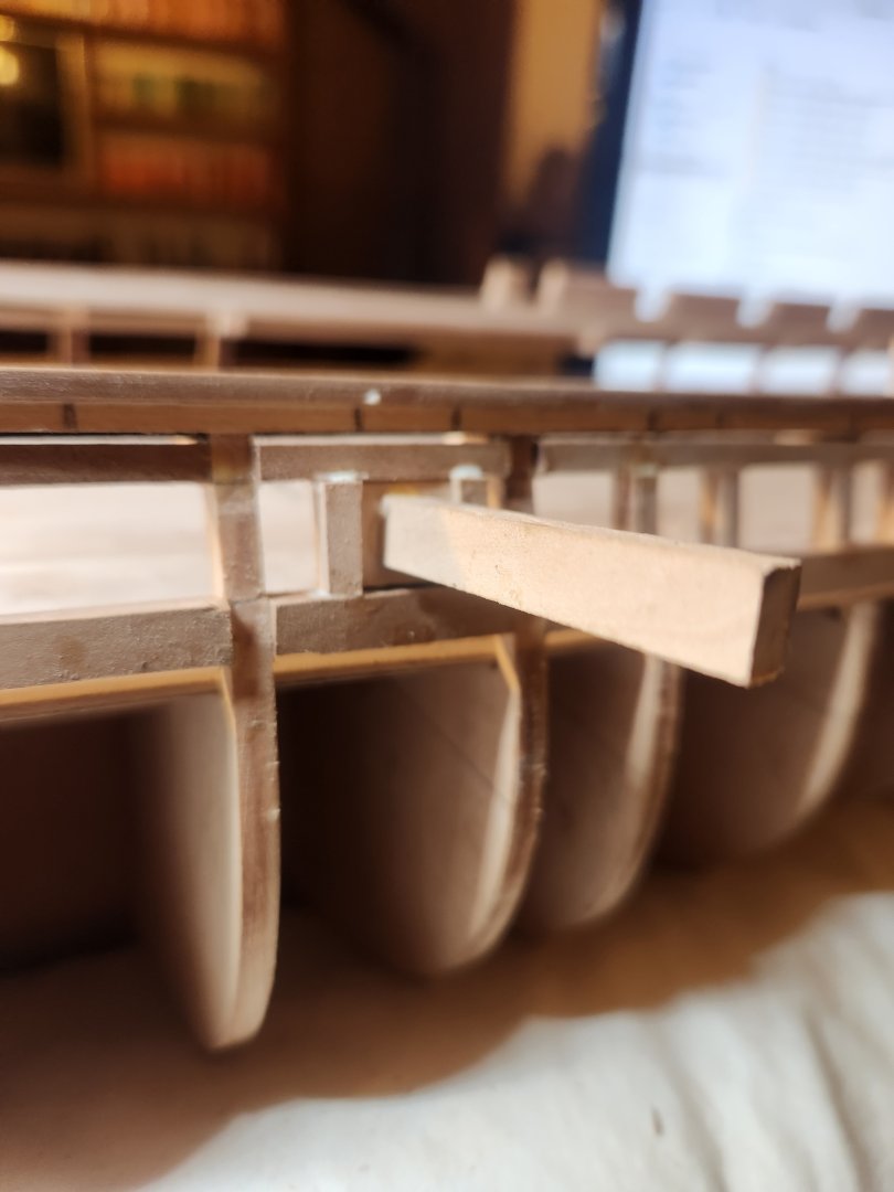
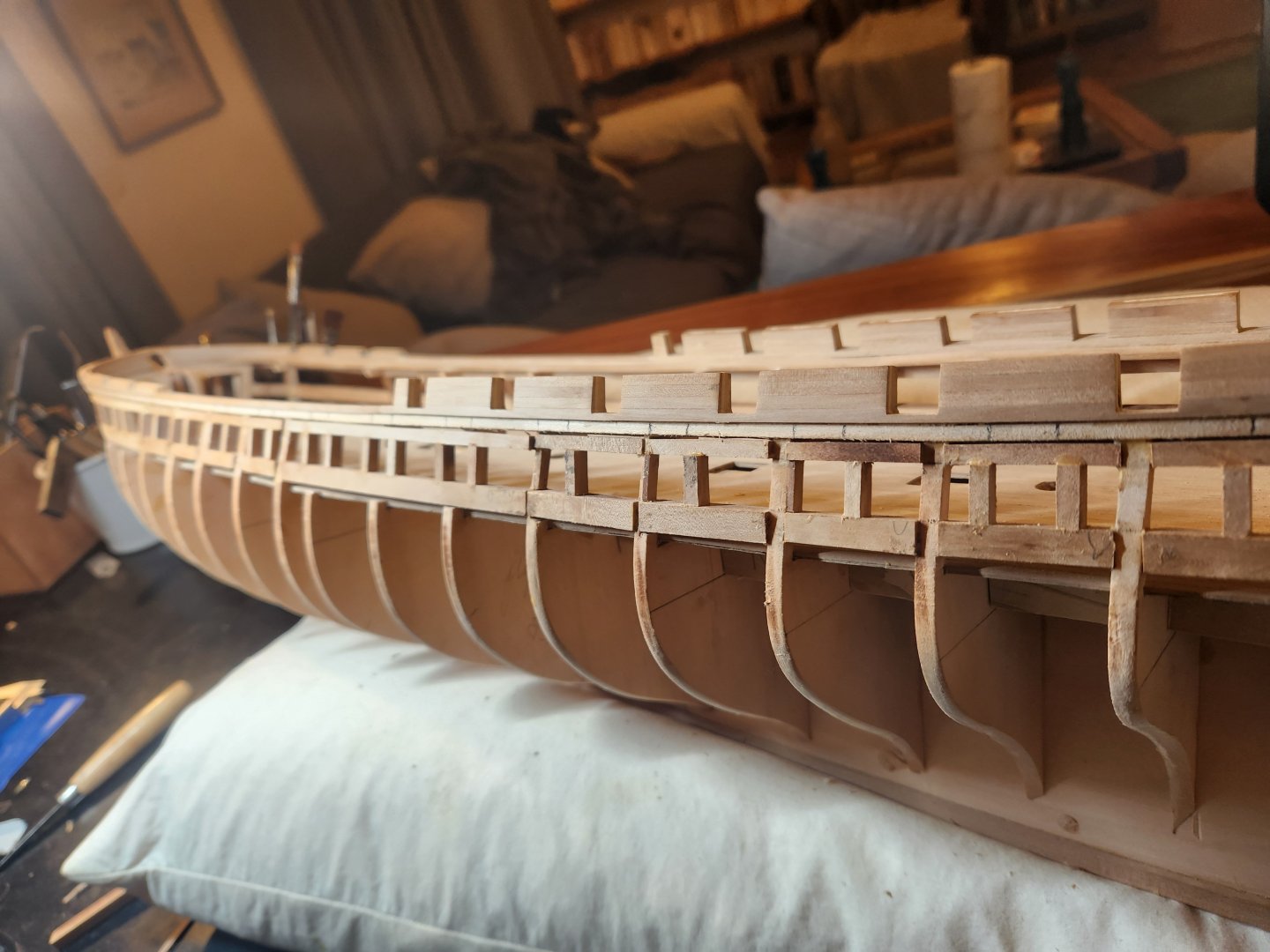
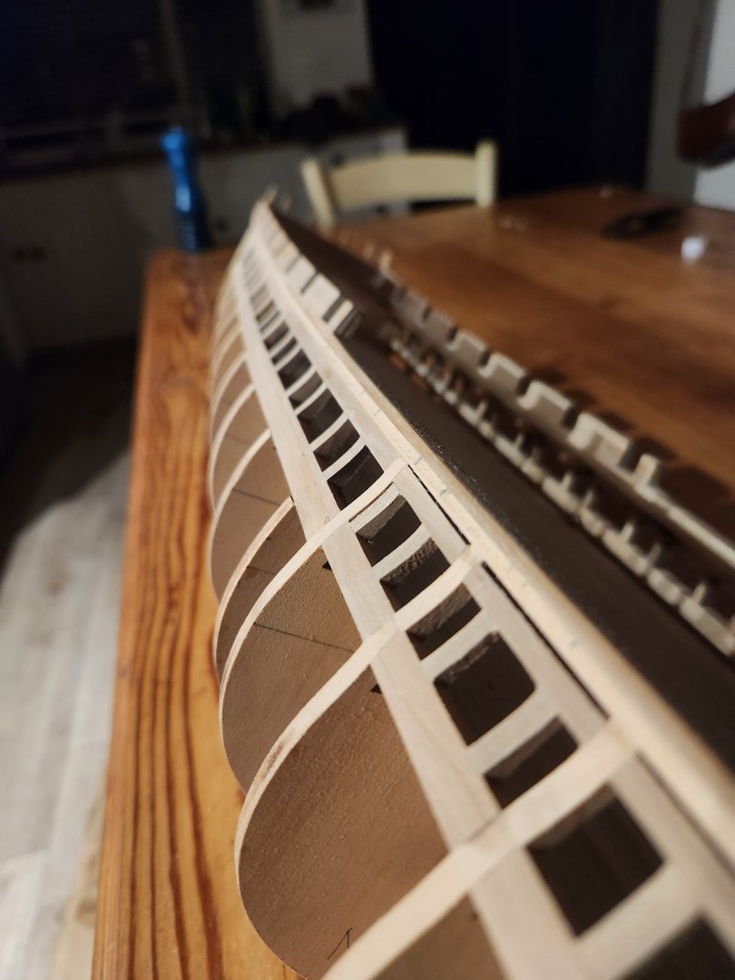
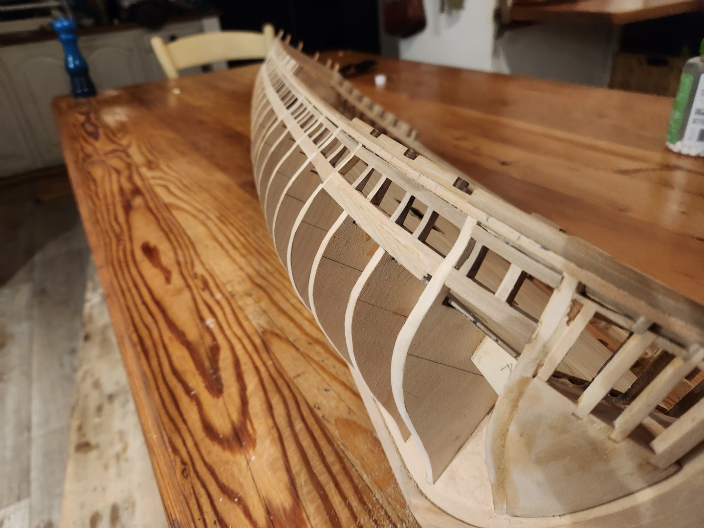
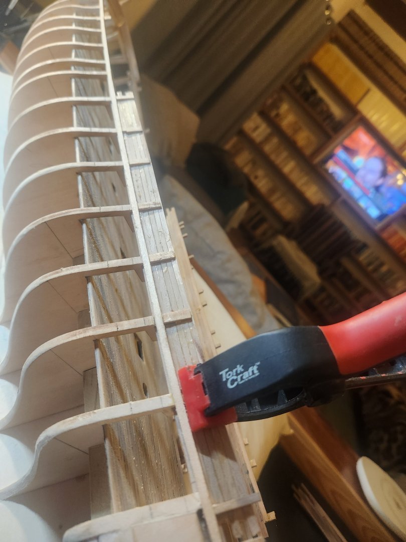
For Framing the gun ports of the gun deck I began by marking out the locations of the gun port on the strake just below the plankshear in pencil. These gun ports are 3.1ft by 3.1ft at full size according to the Doughty plans, 12.3mm at scale. which is slightly larger than the spar deck gun ports. For all reasonable purposes these are located directly centred between the gun ports of the spar deck. Here you can see the pencil marks as well as the X on the frames which need to be removed to accommodate the gun port. Next I marked the upper and lower sills of the ports in pencil on the frames by measuring a uniform distance down from the spar deck to make sure that the gun ports followed the swoop of the spar deck fairly closely. and clamped a single strake to the frames to create on smooth line and did a final marking of both upper and lower sills. I then double checked this against a gun on carriage built to the naval spec. All these measurements dovetailed perfectly resulting in a cannon which was nicely aligned with its port as well as ports which looked fairly well placed to the laymans eye. I then clamped a single long run of plank to the inside of the frames at the level of the lower sill so that I could mark out where the gun ports would land as well as providing a reference surface to put my main gun port sill beams against so that the barrels would all protrude and equal distance from the hull when the carriage was pushed up against the bulkhead on the gun deck. Next was to take pear offcuts of roughly the same size(these were mostly from my learning phase on the table saw. I didnt need a perfectly uniform piece of wood, it just needed to be flat on one side and slightly thicker than the frame so that it could be sanded back when all was said and done. I began with the lower sill, working from aft to forward, removing the frames that were in the way as I went. This did require a bit of steaming and bending to get the sill to follow the correct lines, particularly where the bow curved and where the frames had been removed. This process was then repeated for the upper sill. Please ignore the ragged egdes etc. only the internal frames of the gun ports will be visible after planking. On to the verticals. I made a small template to build the sides of the gun ports around. This ensured square corners and the right uniform width for all ports. Just a 12.3x12.3mm piece of wood on an angled stick. I then installed the verticals. And then some sanding. (I have a blister) Lots more work to do and cleaning up and sanding on the other side to get this done. Cheers TBE


- 233 replies
-
- 5
-
-
-
- Model Shipways
- constitution
- (and 5 more)
-
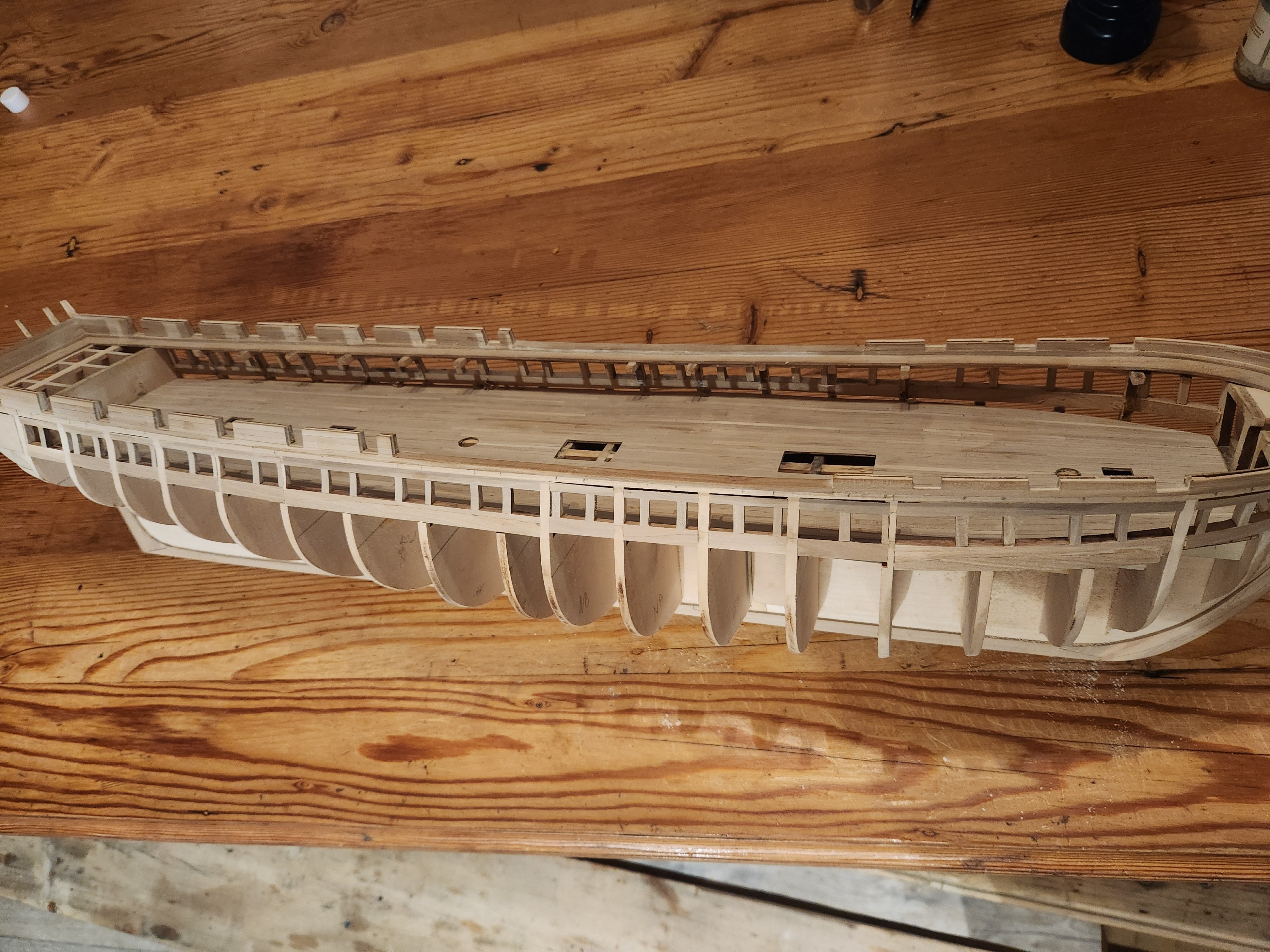
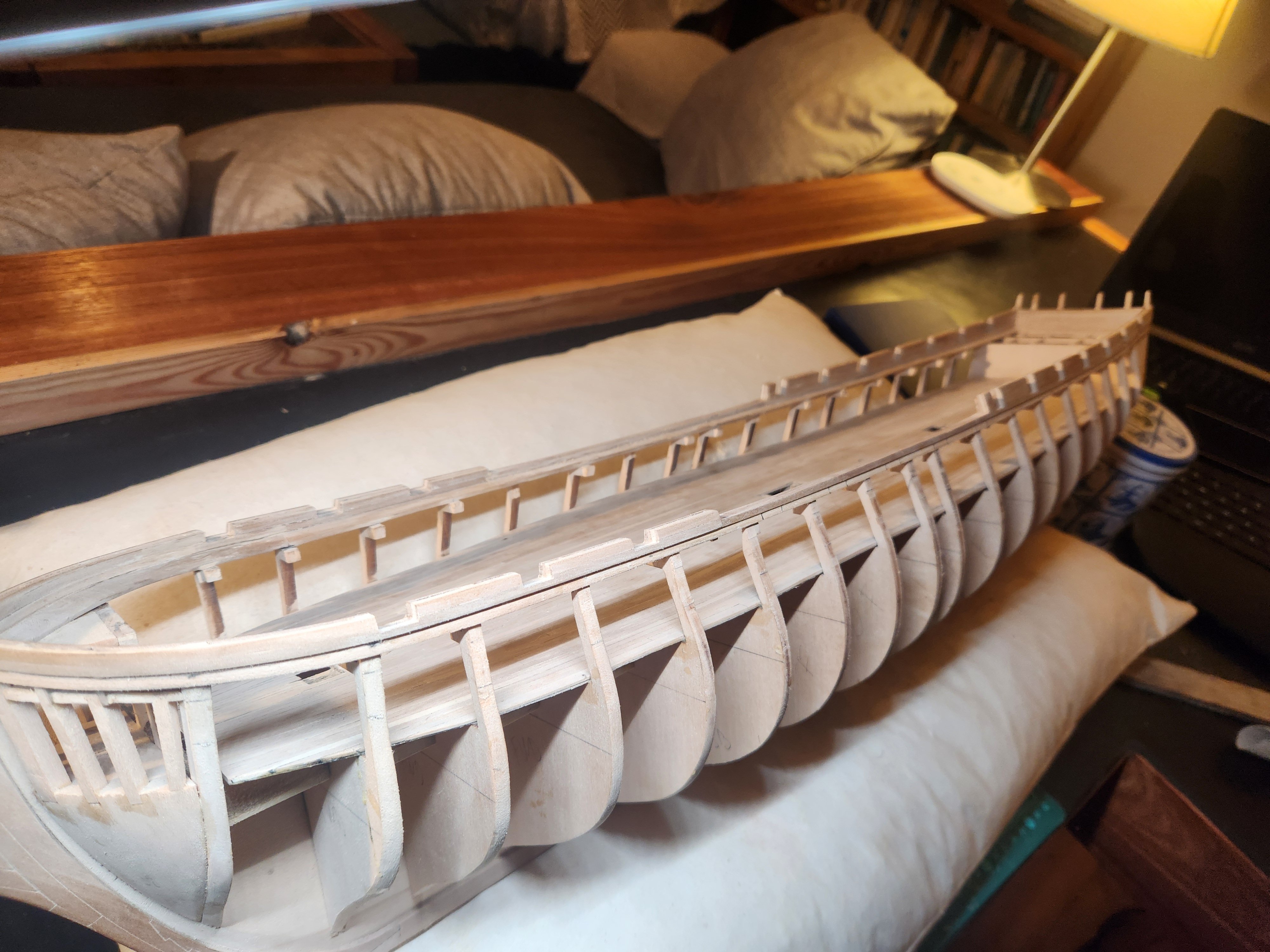
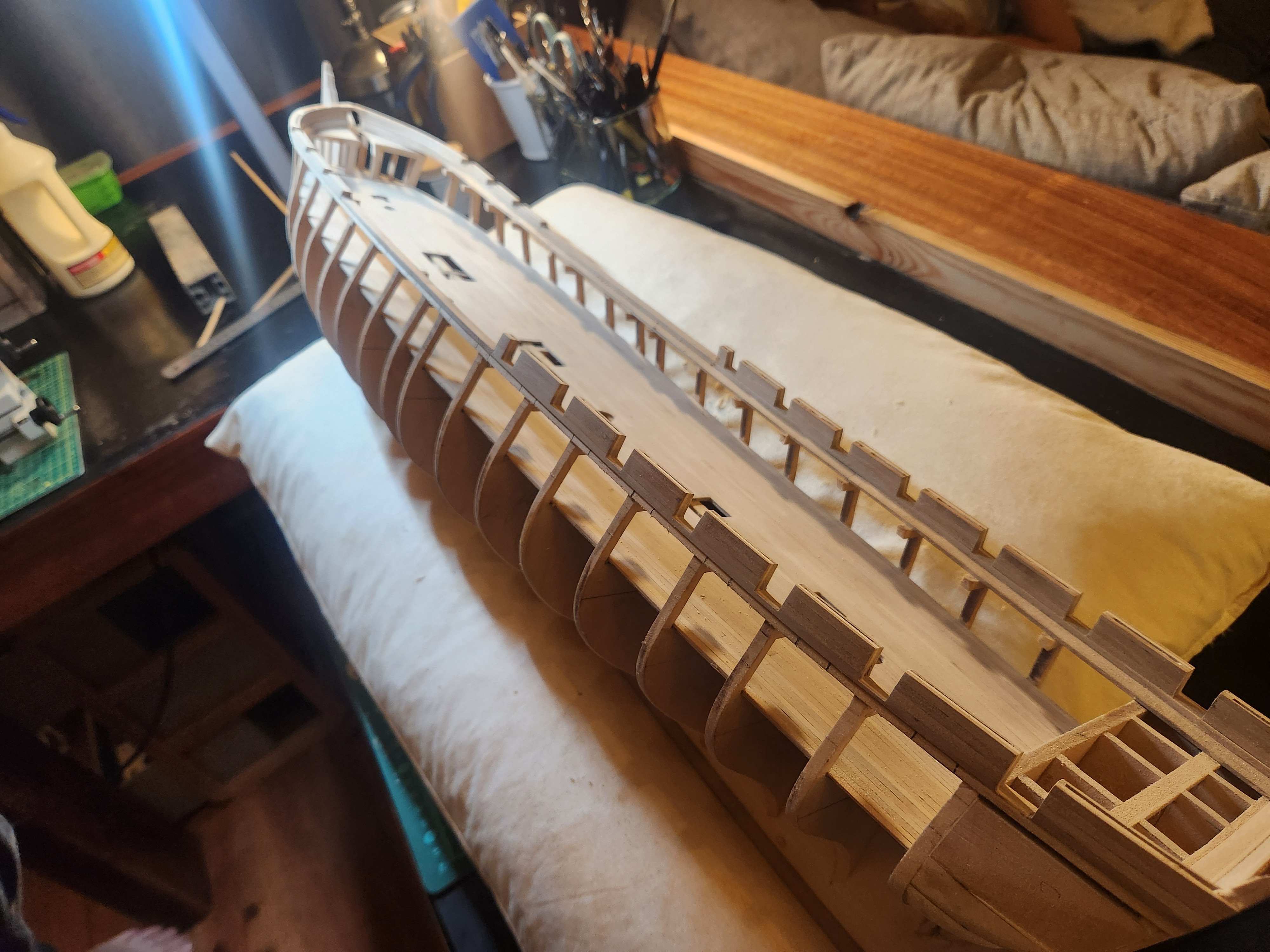
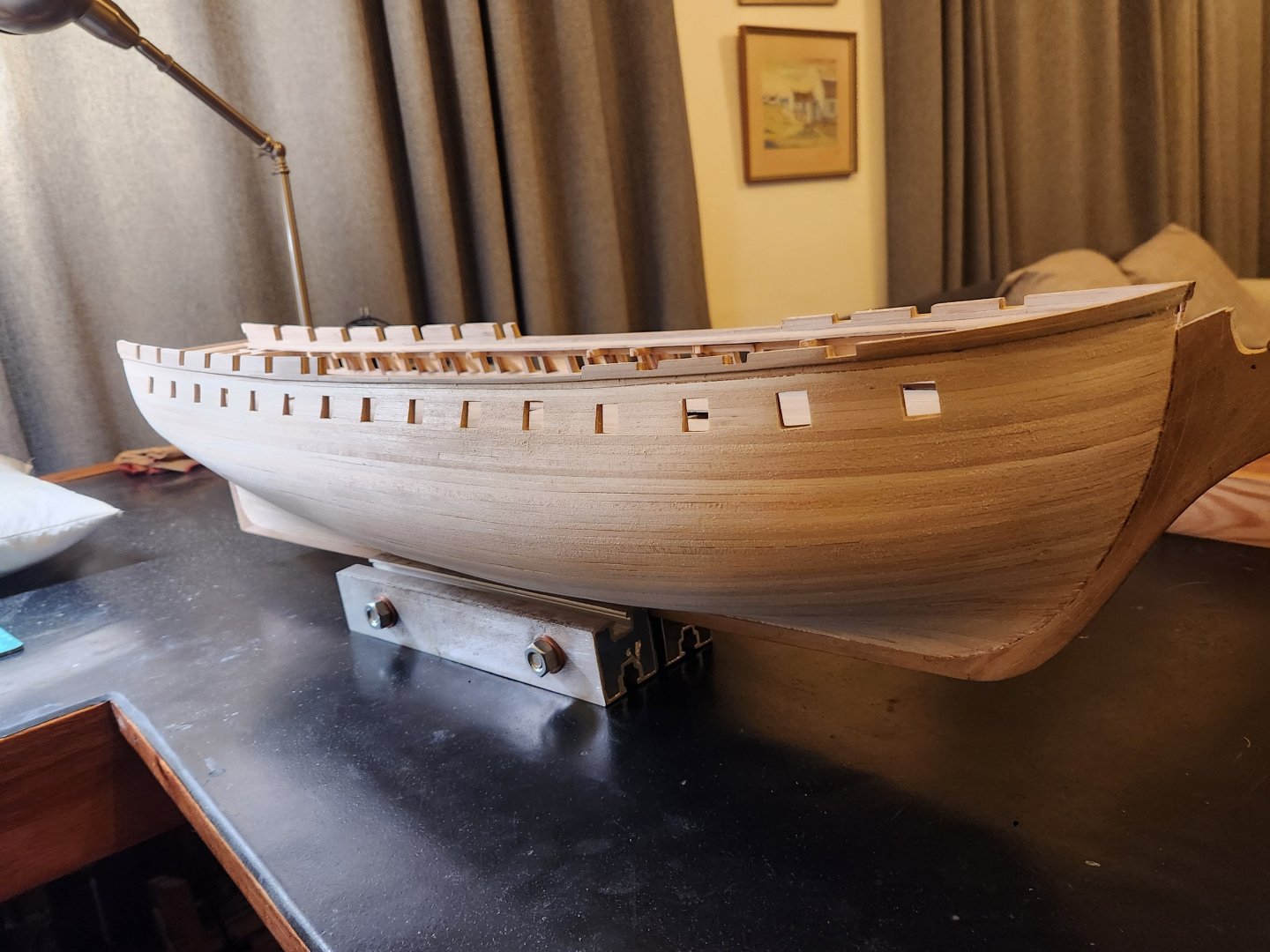
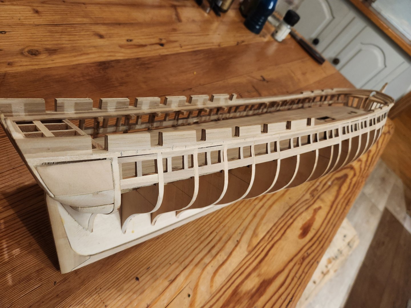
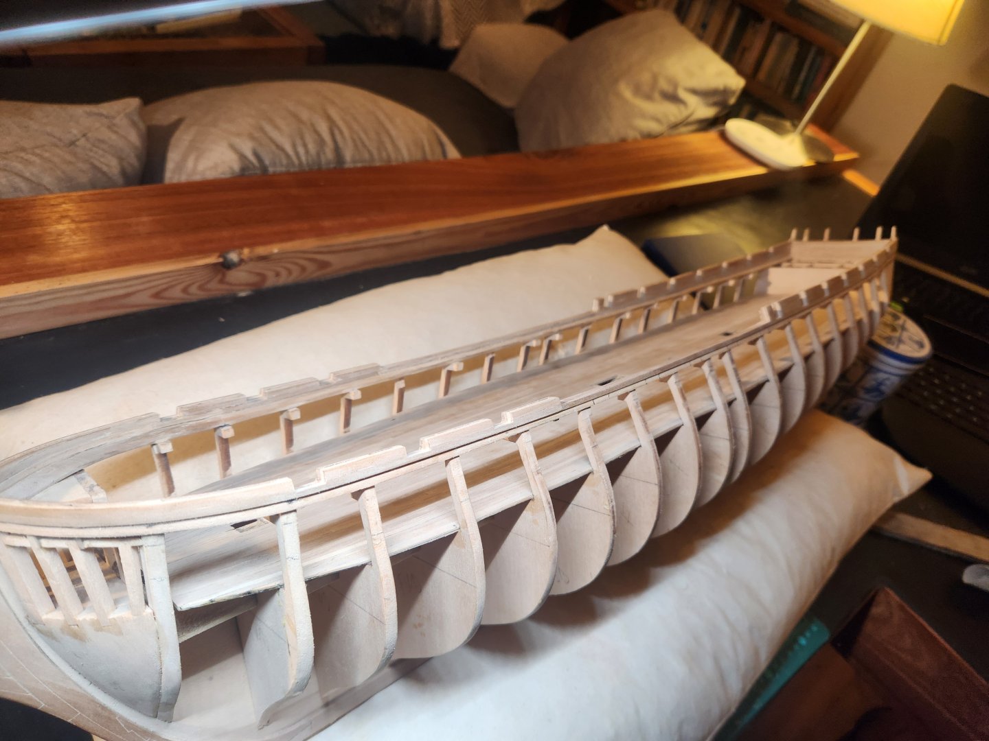
Hello everyone. After the very demoralising step of pulling off all my spar deck gun ports I managed to make some progress again. I dont know how exactly I managed to mess up the gun port placement so badly. Something about measuring once and cutting twice...I can't quite recall...anyway. I won't bore you too much with the repeat process but here are the basics... I couldnt find any drawings of step 1 in the plans: Then repeating the process that was completed in a previous post but this time measuring very carefully and this resulted in a far longer waist than before and slightly more elegant lines. On to the gun deck gun port framing... TBE


- 233 replies
-
- 6
-
-
- Model Shipways
- constitution
- (and 5 more)
-
Hello Marcus Thank you for taking the time to present this information so clearly and including additional sources etc. This is what we need. Also as I said before, What a beautiful painting. These discussions really bring a whole new level of joy to the hobby. Cheers Haiko