

KrisWood
-
Posts
314 -
Joined
-
Last visited
-
 aaronc reacted to a post in a topic:
Oseberg Ship by KrisWood - 1:25 - Vibeke Bischoff Plans
aaronc reacted to a post in a topic:
Oseberg Ship by KrisWood - 1:25 - Vibeke Bischoff Plans
-
mtaylor reacted to a post in a topic:
Redoing Oseberg
-
thibaultron reacted to a post in a topic:
Redoing Oseberg
-
Redoing Oseberg
KrisWood replied to KrisWood's topic in CAD and 3D Modelling/Drafting Plans with Software
@thibaultron OMG that is awesome! Also I learned a thing. I'd thus far been unable to find a translation for the modern Danish word "Lot", old Norse "Undirhlutr". This video taught me the English word "Underlout", which is middle English for "Subordinate". Thank you for sharing! -
KrisWood reacted to a post in a topic:
Redoing Oseberg
-
mtaylor reacted to a post in a topic:
Redoing Oseberg
-
Scottish Guy reacted to a post in a topic:
Redoing Oseberg
-
Redoing Oseberg
KrisWood replied to KrisWood's topic in CAD and 3D Modelling/Drafting Plans with Software
It's been a while. I took a break from drawing while debating with myself over how I want to proceed with the project. I'm having a hard time figuring out how to build it and keep everything square when I don't even know how to build a proper jig. I came down in the side of, I'll just start building and making mistakes. Next step is to finish making the stems solids so I can slice them into layers for printing on card. -
mtaylor reacted to a post in a topic:
Redoing Oseberg
-
Scottish Guy reacted to a post in a topic:
Redoing Oseberg
-
Scottish Guy reacted to a post in a topic:
Redoing Oseberg
-
Redoing Oseberg
KrisWood replied to KrisWood's topic in CAD and 3D Modelling/Drafting Plans with Software
Yeah, vector CAD is an entirely different animal than poly modelers. I actually started learning CAD with 3DS Max a couple decades ago but switched to Rhino for this project. I'll never go back, when it comes to ships at least. It's far easier to draw curves accurately. As for end product, my goal is a paper or wood model. I can't afford a CNC mill at the moment, but I can probably get a laser cutter in the next year or so. In the meanwhile I can print on card to my heart's content so I'm going to do that and cut the layers out by hand and glue them together. I just have to get all the parts into 3D so I can slice them into layers for printing. 🙂 -
KrisWood reacted to a post in a topic:
Redoing Oseberg
-
mtaylor reacted to a post in a topic:
Redoing Oseberg
-
mtaylor reacted to a post in a topic:
Redoing Oseberg
-
Redoing Oseberg
KrisWood replied to KrisWood's topic in CAD and 3D Modelling/Drafting Plans with Software
Ok I figured out how to get it into 3D by using crv2view since I've done the math in front and profile views. Now to figure out how to get solids out of these.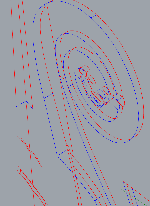

-
Redoing Oseberg
KrisWood replied to KrisWood's topic in CAD and 3D Modelling/Drafting Plans with Software
Here's the problem. The blue lines are easy. They are given in the paper. The stem is 5.5cm wide at the forward edge and at the top of the stem-top, 10.7cm along the inner edge of the rabbet, 15cm at its widest point at the aft edge of the base of the stem-top. The green lines are of unknown length. Their length is determined by where you draw the cross section through the stem, and at what angle. You'll get a different number every time on these depending on how you slice it. You can't just use the cross sections because the length is undetermined in them. I try sweeping the rails using the known dimensions but it comes out all wavy, not a nice straight line like in the plans.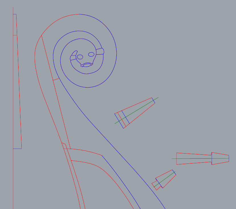
-
Redoing Oseberg
KrisWood replied to KrisWood's topic in CAD and 3D Modelling/Drafting Plans with Software
Ok I'm stumped. Can anyone help me make this 3D in Rhino? -
Redoing Oseberg
KrisWood replied to KrisWood's topic in CAD and 3D Modelling/Drafting Plans with Software
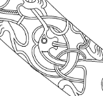
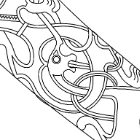
Whoops, right after that last one I realized I'd only done the carvings in profile view. NOW all the carvings are done.
-
Redoing Oseberg
KrisWood replied to KrisWood's topic in CAD and 3D Modelling/Drafting Plans with Software
I got frustrated with trying to make the stems 3D so I focused on 2D instead. All carvings complete!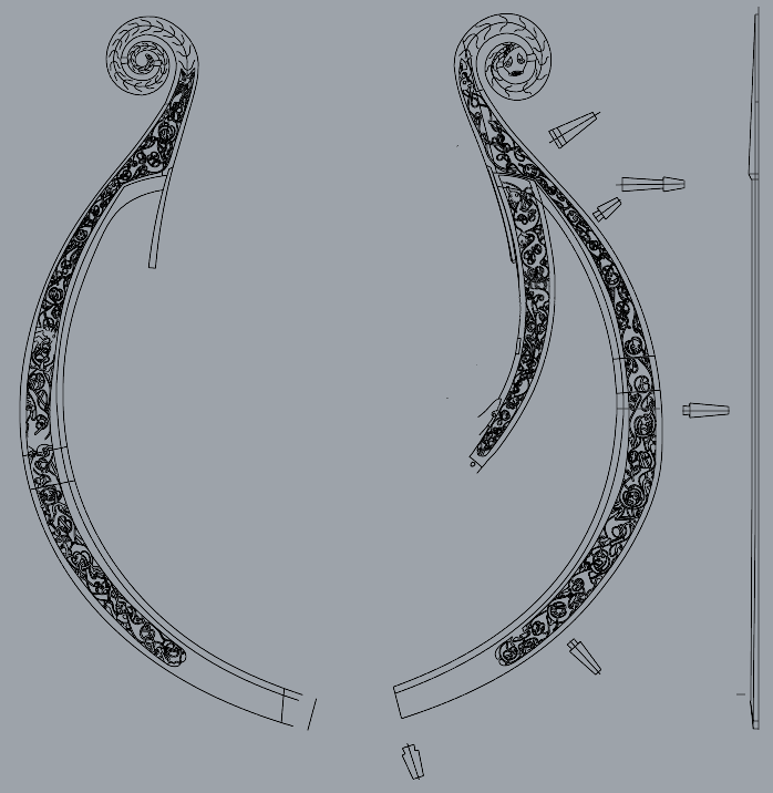
-
Redoing Oseberg
KrisWood replied to KrisWood's topic in CAD and 3D Modelling/Drafting Plans with Software
I've redrawn the fore stem. The cross sections in the original drawings are not to scale so they can't be used directly. I've redrawn the widths of the sections to scale using the numbers from the paper, but cannot reconcile them with the curves of the stems. Can anyone help? I've put my newly drawn stem at 1:10 here as an SVG. How do you draw this in 3D? stem.svg -
Redoing Oseberg
KrisWood replied to KrisWood's topic in CAD and 3D Modelling/Drafting Plans with Software
Got the keel faired. The numbers in the paper are more accurate than those in the Saga Oseberg book.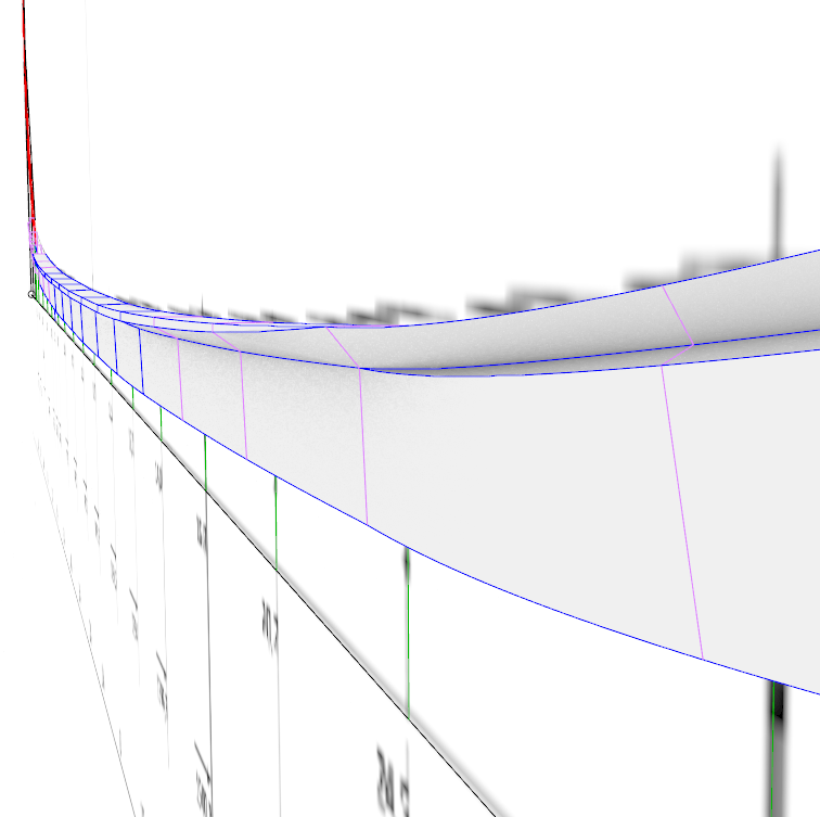

-
Redoing Oseberg
KrisWood replied to KrisWood's topic in CAD and 3D Modelling/Drafting Plans with Software
I'd disagree on one point only. The paper and its contents are intellectual property of the Viking Ship Museum in Roskilde, Denmark. I think as long as we don't redistribute the original PDFs we'll be ok. Edit: I've got the keel and stem cross sections done. Next step is fairing them together and drawing the 3D curves. Edit: The paper's measurements for the keel do not fair, at least at my skill level, so I'm trying again with the numbers from the Saga Oseberg book. I'll update this in a bit when I get a chance.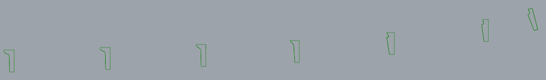
-
Redoing Oseberg
KrisWood replied to KrisWood's topic in CAD and 3D Modelling/Drafting Plans with Software
Also we still need to resolve the question of, if the drawings are based on published plans, are they ours to share? Either way, if you want to follow along, the starting point is to download the plans from the link above. -
Redoing Oseberg
KrisWood replied to KrisWood's topic in CAD and 3D Modelling/Drafting Plans with Software
I think the problem is going to be polygon modelers vs vector. Rhino doesn't work with solid objects as much as it does curves. Does blender support a common vector format? Maybe DWG? -
KrisWood reacted to a post in a topic:
Redoing Oseberg
-
Redoing Oseberg
KrisWood replied to KrisWood's topic in CAD and 3D Modelling/Drafting Plans with Software
I worked page 28 into it but it doesn't quite line up with the rest yet.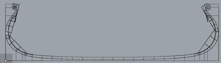
-
KrisWood reacted to a post in a topic:
Redoing Oseberg
-
Redoing Oseberg
KrisWood replied to KrisWood's topic in CAD and 3D Modelling/Drafting Plans with Software
Alright! You'll need to download the plans yourself to use them and I'm not sure how compatible Fusion 360 is with Rhino. First step is coming up with a sane format. Let's see how far we can get. 🙂