KrisWood
-
Posts
314 -
Joined
-
Last visited
Content Type
Profiles
Forums
Gallery
Events
Everything posted by KrisWood
-
Redoing Oseberg
KrisWood replied to KrisWood's topic in CAD and 3D Modelling/Drafting Plans with Software
@thibaultron OMG that is awesome! Also I learned a thing. I'd thus far been unable to find a translation for the modern Danish word "Lot", old Norse "Undirhlutr". This video taught me the English word "Underlout", which is middle English for "Subordinate". Thank you for sharing! -
Redoing Oseberg
KrisWood replied to KrisWood's topic in CAD and 3D Modelling/Drafting Plans with Software
It's been a while. I took a break from drawing while debating with myself over how I want to proceed with the project. I'm having a hard time figuring out how to build it and keep everything square when I don't even know how to build a proper jig. I came down in the side of, I'll just start building and making mistakes. Next step is to finish making the stems solids so I can slice them into layers for printing on card. -
Redoing Oseberg
KrisWood replied to KrisWood's topic in CAD and 3D Modelling/Drafting Plans with Software
Yeah, vector CAD is an entirely different animal than poly modelers. I actually started learning CAD with 3DS Max a couple decades ago but switched to Rhino for this project. I'll never go back, when it comes to ships at least. It's far easier to draw curves accurately. As for end product, my goal is a paper or wood model. I can't afford a CNC mill at the moment, but I can probably get a laser cutter in the next year or so. In the meanwhile I can print on card to my heart's content so I'm going to do that and cut the layers out by hand and glue them together. I just have to get all the parts into 3D so I can slice them into layers for printing. 🙂 -
Redoing Oseberg
KrisWood replied to KrisWood's topic in CAD and 3D Modelling/Drafting Plans with Software
Ok I figured out how to get it into 3D by using crv2view since I've done the math in front and profile views. Now to figure out how to get solids out of these.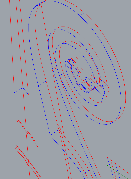

-
Redoing Oseberg
KrisWood replied to KrisWood's topic in CAD and 3D Modelling/Drafting Plans with Software
Here's the problem. The blue lines are easy. They are given in the paper. The stem is 5.5cm wide at the forward edge and at the top of the stem-top, 10.7cm along the inner edge of the rabbet, 15cm at its widest point at the aft edge of the base of the stem-top. The green lines are of unknown length. Their length is determined by where you draw the cross section through the stem, and at what angle. You'll get a different number every time on these depending on how you slice it. You can't just use the cross sections because the length is undetermined in them. I try sweeping the rails using the known dimensions but it comes out all wavy, not a nice straight line like in the plans.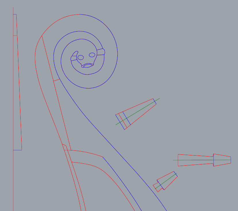
-
Redoing Oseberg
KrisWood replied to KrisWood's topic in CAD and 3D Modelling/Drafting Plans with Software
Ok I'm stumped. Can anyone help me make this 3D in Rhino? -
Redoing Oseberg
KrisWood replied to KrisWood's topic in CAD and 3D Modelling/Drafting Plans with Software
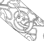
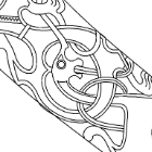
Whoops, right after that last one I realized I'd only done the carvings in profile view. NOW all the carvings are done.
-
Redoing Oseberg
KrisWood replied to KrisWood's topic in CAD and 3D Modelling/Drafting Plans with Software
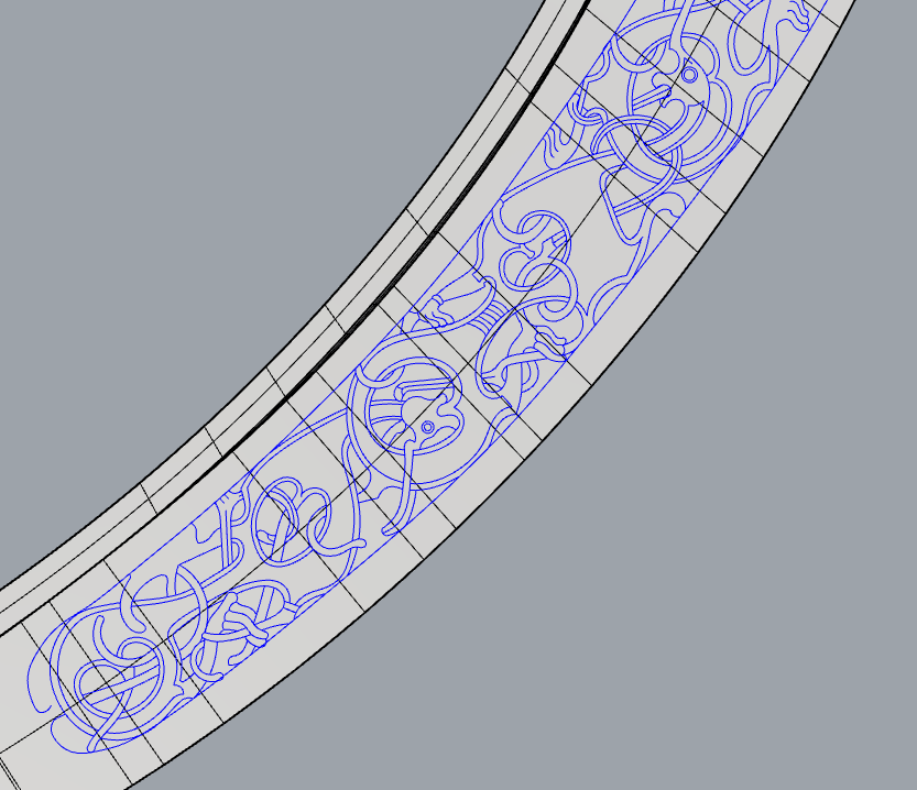
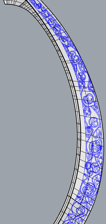
I got frustrated with trying to make the stems 3D so I focused on 2D instead. All carvings complete!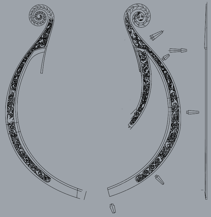
-
Redoing Oseberg
KrisWood replied to KrisWood's topic in CAD and 3D Modelling/Drafting Plans with Software
I've redrawn the fore stem. The cross sections in the original drawings are not to scale so they can't be used directly. I've redrawn the widths of the sections to scale using the numbers from the paper, but cannot reconcile them with the curves of the stems. Can anyone help? I've put my newly drawn stem at 1:10 here as an SVG. How do you draw this in 3D? stem.svg -
Redoing Oseberg
KrisWood replied to KrisWood's topic in CAD and 3D Modelling/Drafting Plans with Software
Got the keel faired. The numbers in the paper are more accurate than those in the Saga Oseberg book.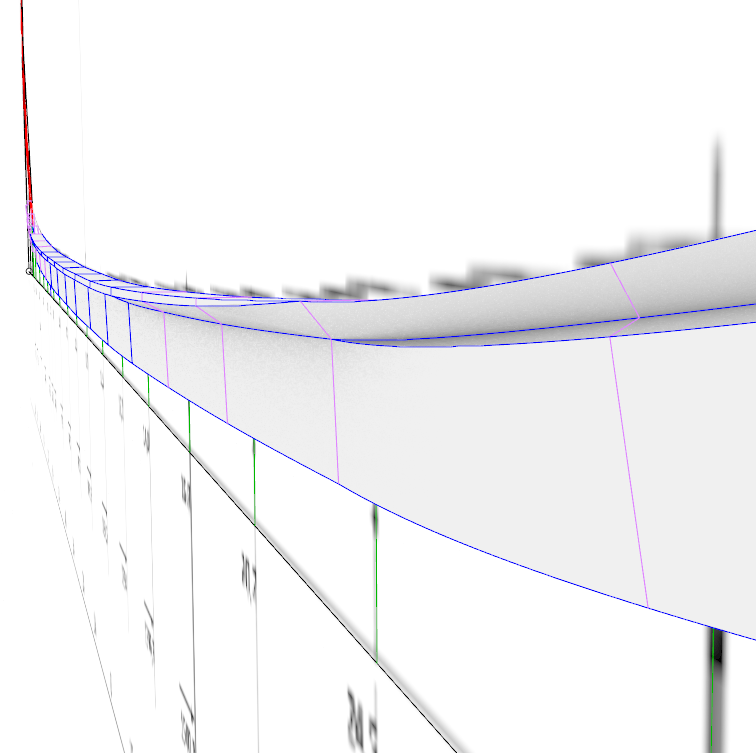

-
Redoing Oseberg
KrisWood replied to KrisWood's topic in CAD and 3D Modelling/Drafting Plans with Software
I'd disagree on one point only. The paper and its contents are intellectual property of the Viking Ship Museum in Roskilde, Denmark. I think as long as we don't redistribute the original PDFs we'll be ok. Edit: I've got the keel and stem cross sections done. Next step is fairing them together and drawing the 3D curves. Edit: The paper's measurements for the keel do not fair, at least at my skill level, so I'm trying again with the numbers from the Saga Oseberg book. I'll update this in a bit when I get a chance.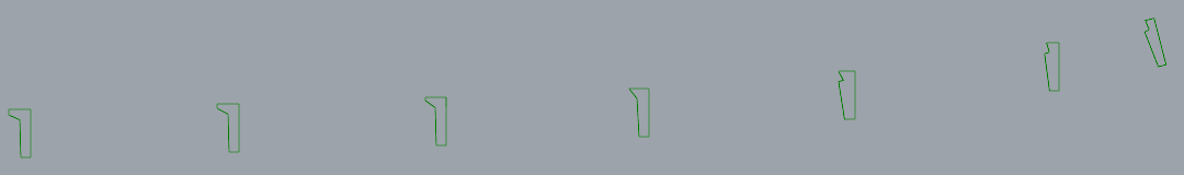
-
Redoing Oseberg
KrisWood replied to KrisWood's topic in CAD and 3D Modelling/Drafting Plans with Software
Also we still need to resolve the question of, if the drawings are based on published plans, are they ours to share? Either way, if you want to follow along, the starting point is to download the plans from the link above. -
Redoing Oseberg
KrisWood replied to KrisWood's topic in CAD and 3D Modelling/Drafting Plans with Software
I think the problem is going to be polygon modelers vs vector. Rhino doesn't work with solid objects as much as it does curves. Does blender support a common vector format? Maybe DWG? -
Redoing Oseberg
KrisWood replied to KrisWood's topic in CAD and 3D Modelling/Drafting Plans with Software
I worked page 28 into it but it doesn't quite line up with the rest yet.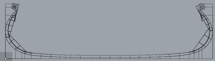
-
Redoing Oseberg
KrisWood replied to KrisWood's topic in CAD and 3D Modelling/Drafting Plans with Software
Alright! You'll need to download the plans yourself to use them and I'm not sure how compatible Fusion 360 is with Rhino. First step is coming up with a sane format. Let's see how far we can get. 🙂 -
Redoing Oseberg
KrisWood replied to KrisWood's topic in CAD and 3D Modelling/Drafting Plans with Software
Anyone want to collaborate? I could use some help with fairing and integrating the various parts into the model. I can do initial drawings of all the parts but they may or may not fit. This part was already done on my lost backups but they're lost. 🤷♂️ -
Redoing Oseberg
KrisWood replied to KrisWood's topic in CAD and 3D Modelling/Drafting Plans with Software
Re-drawing things I've already drawn a million times is exhausting so I went to dig up my backups of the project. They're gone. The most recent one in the cloud is from three years ago. This will be painful.... -
Redoing Oseberg
KrisWood replied to KrisWood's topic in CAD and 3D Modelling/Drafting Plans with Software
First step is trying to read the numbers from https://www.academia.edu/49550641/Rekonstruktion_af_Osebergskibet_Bind_II plan 2 (page 26). This will be necessary for the curvature of the keel, which is what all other numbers are based on. I've got all the numbers plugged in from page 29. The green lines are the stations. Lines below the base line are ones for which no height was given in the plans.
-
Redoing Oseberg
KrisWood replied to KrisWood's topic in CAD and 3D Modelling/Drafting Plans with Software
Hi all! It's been a while. I had to take some time away while life got in the way of hobbies. Things are settling down now and I'm thinking about picking this up again. This time around I'd like to start over and do it open source. Most of the lines can be derived mathematically. Some of the lines cannot be derived mathematically and must be based on existing reconstructions. My question is, if my CAD files are drawn by hand by me, how different must they be from existing plans to count as original work? -
Redoing Oseberg
KrisWood replied to KrisWood's topic in CAD and 3D Modelling/Drafting Plans with Software
That is what I thought. I found the equivalent of Max's FFD boxes. It's called Cage and CageEdit. It takes a little getting used to but gets it into the right ballpark and I can improvise from there, though it's never going to be exactly accurate. -
Redoing Oseberg
KrisWood replied to KrisWood's topic in CAD and 3D Modelling/Drafting Plans with Software
Two questions for you all... 1. How do you project curves onto a surface in Rhino? 2. My reference materials from the stems are, I think, based on Johannessen's reconstruction drawings and Sofie Krafft's detailed drawings of the carvings. They do not line up with Ms Bischoff's reconstruction. In my game modeling days in 3D Studio Max there was a tool called Free Form Deformation that could scoot curves into place en-mass in situations like this. Is there an equivalent in Rhino?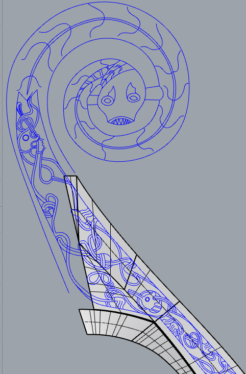
-
Redoing Oseberg
KrisWood replied to KrisWood's topic in CAD and 3D Modelling/Drafting Plans with Software
Now to do the aft stem and then I'll be ready to slice it into printable layers. Edit: oh wait, I still need to figure out how to project the carvings onto the stems...
-
Redoing Oseberg
KrisWood replied to KrisWood's topic in CAD and 3D Modelling/Drafting Plans with Software
And next question is, depth of rabbets, drawn in CAD or just the placement of the rabbets and cut them to depth physically when building? Edit: Here's a fun diagram to explain how to draw the depth of the rabbets on any Viking ship that has them. It's actually surprisingly easy. The following is a cross section of the stem at a point where I have no numbers beyond those calculated from the documentation for top and bottom width of the keel / stems. The plans have lines for the top and bottom of the rabbet and the bottom of the keel in profile view. I've drawn these as horizontal lines in RED. Given the measurements of the widths from the documentation, I can now make a trapezoid shape connecting the dots, which I've done in BLUE. Next I draw the depth of the keel as two circles, centered at the intersection of the red lines with the blue line, which I've drawn in GREEN. I'm not bothering to taper my planks, so my circles have a diameter of 2.5cm along the entire length of the keel / stems. To get the correct ANGLE of the rabbets, draw a line connecting the two circles from the intersection of the top circle with the top red line to the tangent of the bottom circle, which will give a perfect right angle to the bottom of the rabbet, drawn in BLACK.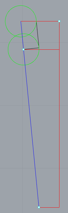
-
Redoing Oseberg
KrisWood replied to KrisWood's topic in CAD and 3D Modelling/Drafting Plans with Software
Question: Is there a good (free?) automated tool for importing ship plan drawings from any raster format into any vector format which can be imported into Rhino? I've tried a number of methods but they all end up with curves drawn as bubbles around the black lines rather than through the middle of the black lines. I've got photoshop if anyone knows of a method there as well. -
Redoing Oseberg
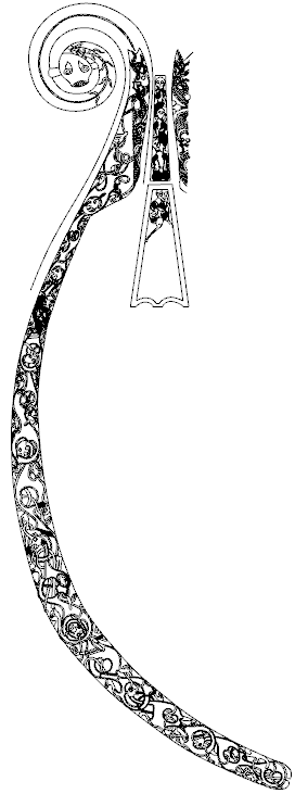
KrisWood replied to KrisWood's topic in CAD and 3D Modelling/Drafting Plans with Software
Finished the port-side fore-stem carvings, moving on to the "tingl".