Matrim
-
Posts
1,401 -
Joined
-
Last visited
Recent Profile Visitors
2,880 profile views


-
 Mr Whippy reacted to a post in a topic:
Bounty by Matrim - FINISHED - Caldercraft - 1:64
Mr Whippy reacted to a post in a topic:
Bounty by Matrim - FINISHED - Caldercraft - 1:64
-
Mr Whippy reacted to a post in a topic:
Bounty by Matrim - FINISHED - Caldercraft - 1:64
-
Mr Whippy reacted to a post in a topic:
Bounty by Matrim - FINISHED - Caldercraft - 1:64
-
Mr Whippy reacted to a post in a topic:
Bounty by Matrim - FINISHED - Caldercraft - 1:64
-
Mr Whippy reacted to a post in a topic:
Bounty by Matrim - FINISHED - Caldercraft - 1:64
-
Mr Whippy reacted to a post in a topic:
Bounty by Matrim - FINISHED - Caldercraft - 1:64
-
Mr Whippy reacted to a post in a topic:
Bounty by Matrim - FINISHED - Caldercraft - 1:64
-
Mr Whippy reacted to a post in a topic:
Bounty by Matrim - FINISHED - Caldercraft - 1:64
-
Mr Whippy reacted to a post in a topic:
Bounty by Matrim - FINISHED - Caldercraft - 1:64
-
Mr Whippy reacted to a post in a topic:
Bounty by Matrim - FINISHED - Caldercraft - 1:64
-
Matrim reacted to a post in a topic:
HBMS Amphion 1798 by Matrim - 32 Gun 18pdr Frigate
-
Stuff is still happening though my updates are not particularly good. I spent some time on the transom plans which can be seen in the thread here and those are now done (whether I have to re-draw when wood is cut remains to be seen - at the moment I'm waiting until next month when I can afford some more fixogum before starting some test pieces. In the meantime I switched back to frames which will need doing sometime. My frame structure will be staggered (at least that's the intention) so when building the individual frame plans I am putting a horizontal line at the furthest point of the frame then the individual futtock can be sized accordingly when cutting onto the model. I am also keeping both forward and reverse lines on all plans (red and blue with Waynes guide). On the mid frames there is bugger all difference but there is slight. I am also 'just' using one line to build the relevant thickness for the inside where I am less worried about the slight shape differences - this will change when moving away from amidships as having the inside bevel will help fairing. One other thing I did was to print one of the central frames out and stick it on cardboard and then just test fit on the keel to see if it 'looked' right. Seemed okay once I had counterbalanced the weird balancing of very thin cardboard

-
Transom Build Plans
Matrim replied to Matrim's topic in CAD and 3D Modelling/Drafting Plans with Software
Thanks all, with the extra waterlines I am happily drawing out the easier filler frames first before moving to the angles on the wing/deck -
Matrim reacted to a post in a topic:
Transom Build Plans
-
Matrim reacted to a post in a topic:
Transom Build Plans
-
Matrim reacted to a post in a topic:
Transom Build Plans
-
Matrim reacted to a post in a topic:
Transom Build Plans
-
Matrim reacted to a post in a topic:
Transom Build Plans
-
Matrim reacted to a post in a topic:
Transom Build Plans
-
Matrim reacted to a post in a topic:
Transom Build Plans
-
Matrim reacted to a post in a topic:
Transom Build Plans
-
Transom Build Plans
Matrim replied to Matrim's topic in CAD and 3D Modelling/Drafting Plans with Software
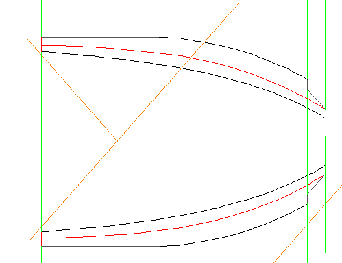
Bleugh , nomenclature incorrect, it is new station lines I want... So I decided to do this so I could improve the curve. The gap between station lines on the sheer around this area of the plan is 62 inches so I added 4 new station lines beyond the last station and one more in front of it at 15.5inch gaps. (Following image shows 'new' station lines in pink with the top one highlighted in red with the vertical constructions at the waterline points made) I then pushed a construction line up from the relevant waterlines and connected on the body plan to get the correct representation higher up. First image shows the same line as above generated, the lower all the new stations on the body Now I have more lines of reference for generating the shape of the transoms on the sheer.
-
Transom Build Plans
Matrim replied to Matrim's topic in CAD and 3D Modelling/Drafting Plans with Software
It would be easier if I could add some extra waterlines the problem being how to draw on the sheer.. -
Transom Build Plans
Matrim replied to Matrim's topic in CAD and 3D Modelling/Drafting Plans with Software
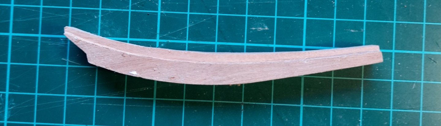
Made my first attempt at the lowest filler transom using a combination of the master plan and inner post. It helped when someone pointed out that the inside line is not terribly important as its non viewable and as long as the shape is tracked anything which might use it can then be adjusted accordingly. With that said my approach was to throw constructions down to the sheer and do an entire waterline then to trim using the body to the correct size I could then use the inner post plan to add the correct chunk for the joint and then took an approximate size for the width If there is anything hideously wrong with the approach then please shriek! One curiosity Turbocad wise was that I found the control points curve was happier with this than the bezier. One thing done differently to the pictures above was that the width of the joint is slightly wider than the keel so I took the start point from there in the end. This piece still needs the scores for the vertical filler pieces on the bottom side (which will be done at the end). I won't start on the rest of the filler pieces until Tuesday and I think I will switch to drawing them all on the master plan mainly so I have a track of where they are (the master plan is quite large at the moment) but that keeps the parts in a consistent location.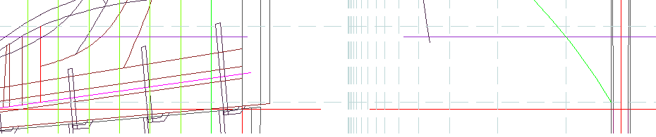
-
Transom Build Plans
Matrim replied to Matrim's topic in CAD and 3D Modelling/Drafting Plans with Software
thanks both. That 'use the deck plan' for one of them (plus some extra for fairing) is a lovely idea. I can also then take that one and project back on the plan to see where the waterlines would be and then extrapolate the opposite for the others... Crag gets extra points for using the actual plans of the ship I am building in his response (that was a surprise - I looked and thought - hold on that's my ship, I must have mis-read) -
Matrim reacted to a post in a topic:
Transom Build Plans
-
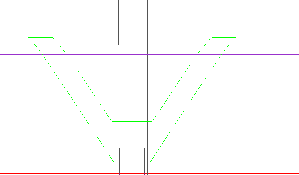
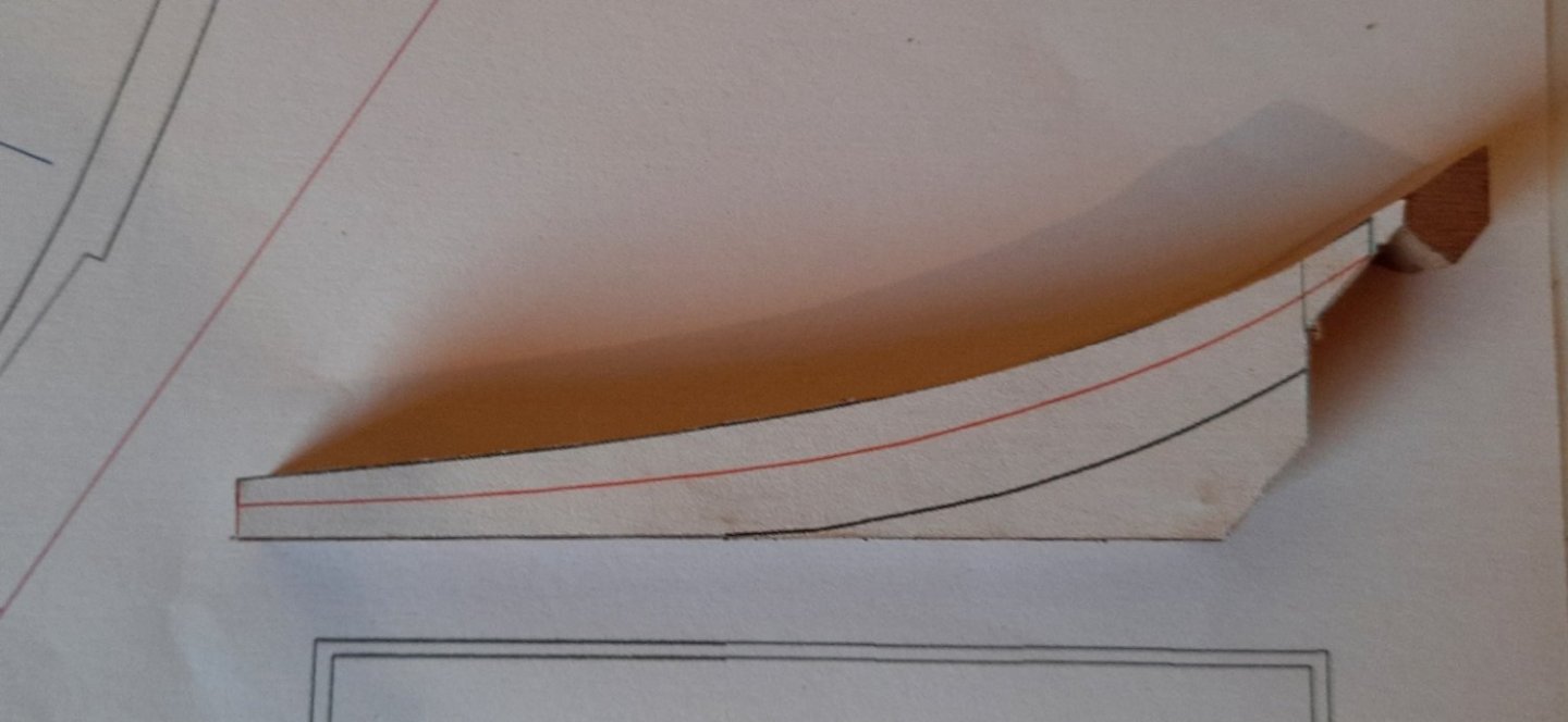
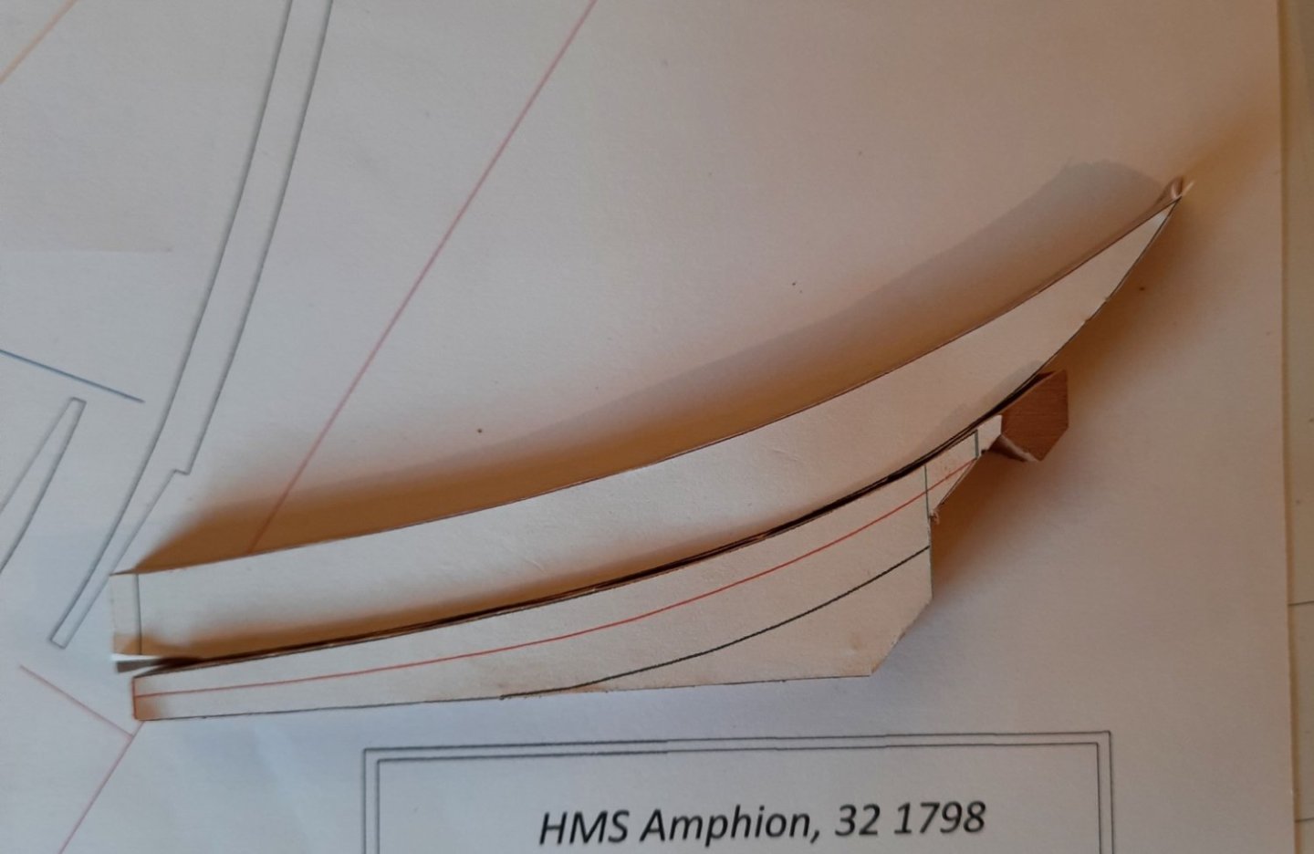
Evening all. Having just finished the stern post/inner post and attached to the keel I am not turning my attention to the wing transom/deck transom and 4 filling transoms. Now these appear to be complicated little beasties. From a plan perspective my plans have several cutaways of what I assume is the central spine of the transom and the frame plan has what I am guessing is possibly an end point (or middle end perhaps). I also have the fashion piece marked which is the end point. Is there a logical way to describe how to work out the correct size of one of these (once one is done the others would duplicate the approach). I am guessing construction lines projected but am unsure so looking for assistance from the plans masters out there. Once these are out of the way then the cant/full frames will fill my time for a year or 2 and Wayne Kempson's wonderful CAD drafting plan covers how to create those in details so I will be good cad wise after these are done. If anyone has any pointers on how to plan one of these out then I would be grateful. For those just interested but without knowledge here is a cad view of the area in question with the transoms in green and the fashion piece (I think) in pink and from the actual plans we have the body plan frame plan with a curious wing shape and the internal fittings plan
-
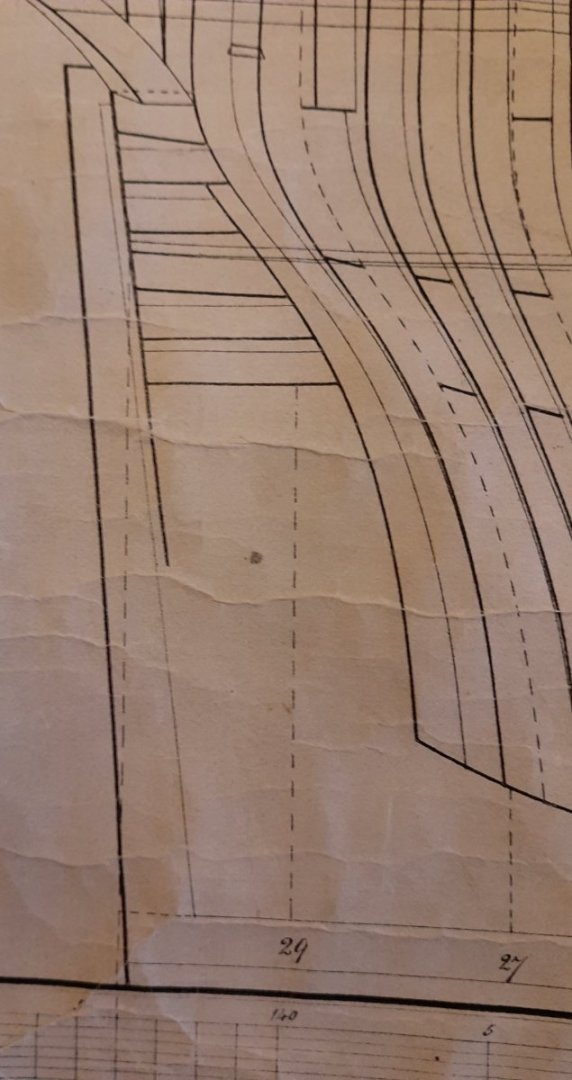
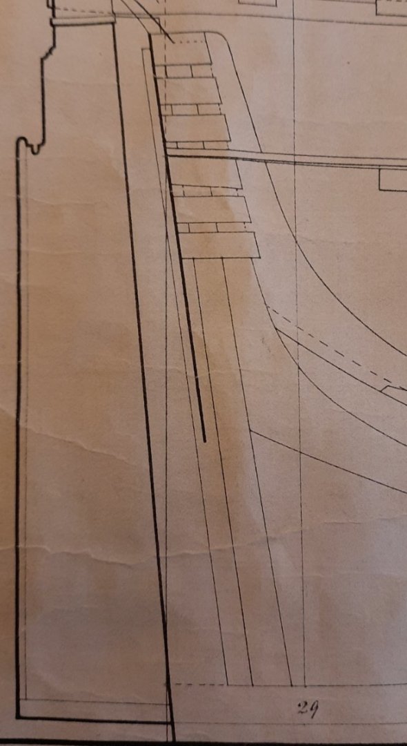
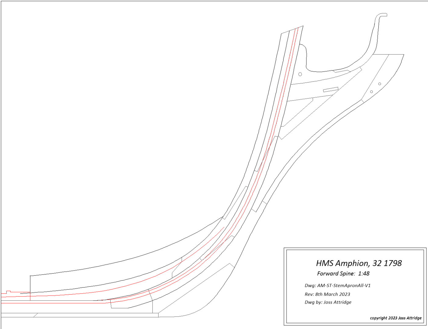
Stem/Apron depth
Matrim replied to Matrim's topic in Building, Framing, Planking and plating a ships hull and deck
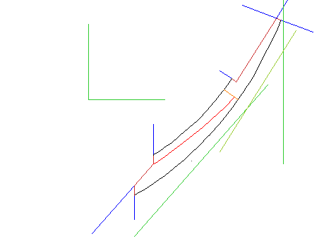
thanks, though isn't that the knee of the head? I have must replaced my pc and my turbocad program is refusing to activate so once that is sorted I will add a direct plan of the part in question. Sorry for any confusion (though the knee information will be useful when i move to that section) -
Sorry for the probably bad nomenclature.. I am looking now at shaping my stem/apron. From the front it seems logical - all books I have have a shape to the follow so I can print a template and stick it to the front. What is confusing me somewhat is whether or not the depth tapers as well or is the side size the same across its length...The Swam books have a dual taper (so 14'' top to 10'' at keel) and 12'' keel to 10'' at boxing - though this looks to me more like the default keel tapering and not a taper impacting the rest of the apron? My guess is that the side width is stable and the front width tapers around to plan. But if someone could confirm either way then that would be great.. (It's with regard to me 32 gun Amphion in case that's relevant - the sizes will obviously be larger than the Swan)
-
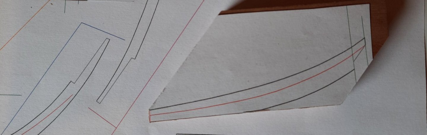
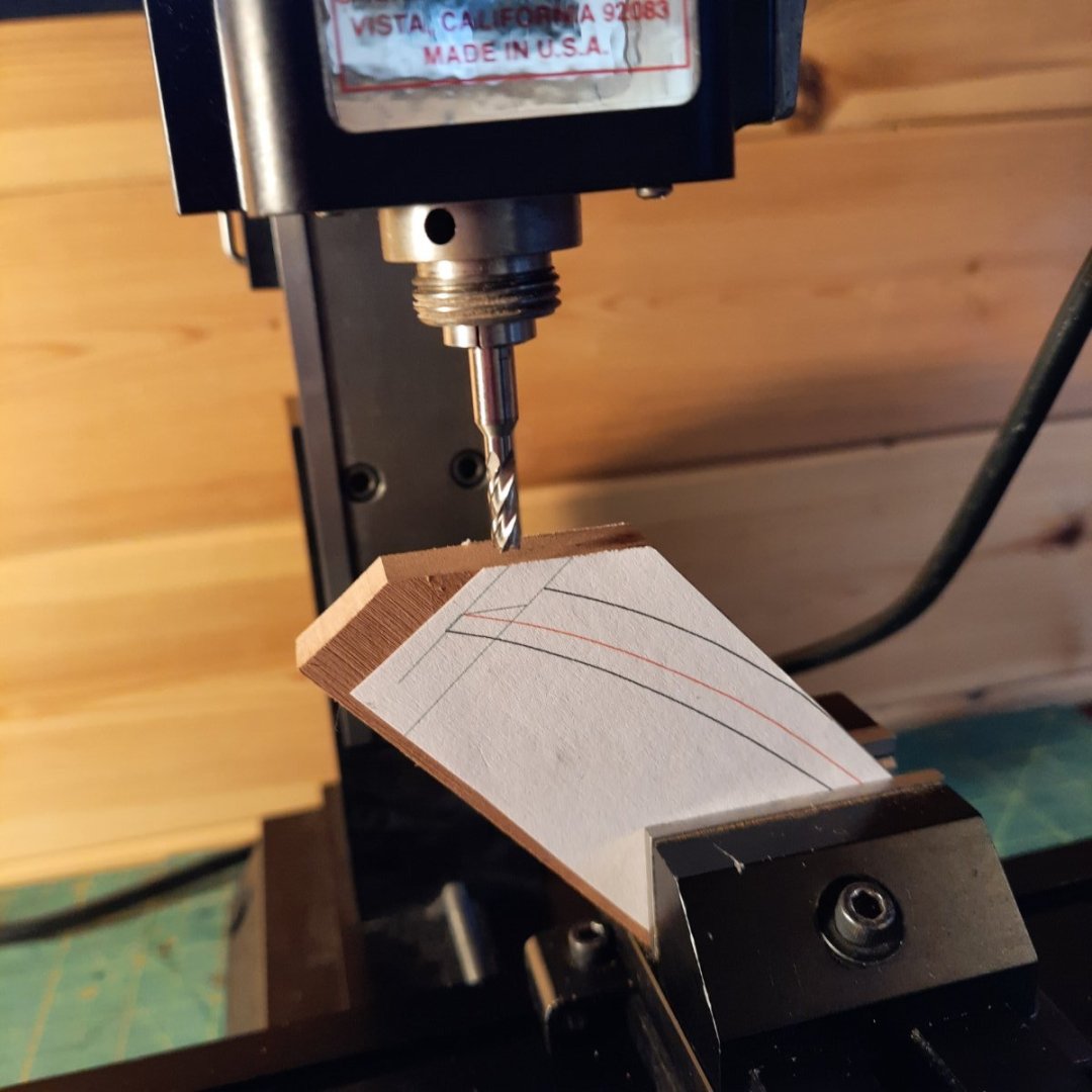
Couple of plan shots while I work on the middle and upper apron. First up I am gradually refining my technique when creating build templates. My new structure is to extend the edges of joints with blue lines (the joints themselves being a burnt red), these lines are then used as a cut check when milling so I can start on the extension line and move inwards. I am also adding a lot of opposing green lines (I may even double these up in future). I use these as table saw cut lines that allow me place the wood at these points and know that (hopefully..) the actual cut line being milled will then be horizontal. Example for middle apron - it looks complex (which is why I simplified the colours) but does help when cutting. The next plan (just done now) is a combined view of the forward keel, apron stem and some other. I plan to use this to ensure the eventual combined apron and stem is accurate.
-
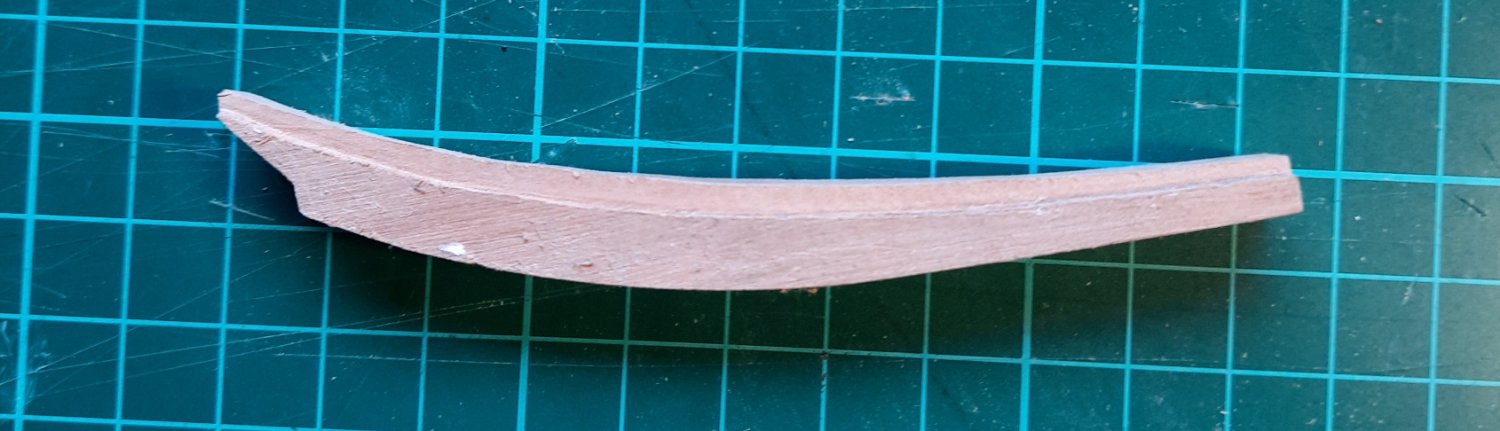
Tidied up the sides of the piece and gap dry fitted to the pieces above and below. Leaving the 'extra' below the shelf (which will eventually by angled to allow the planks to sit) as I have generally read its better to leave 'meat' there..

-
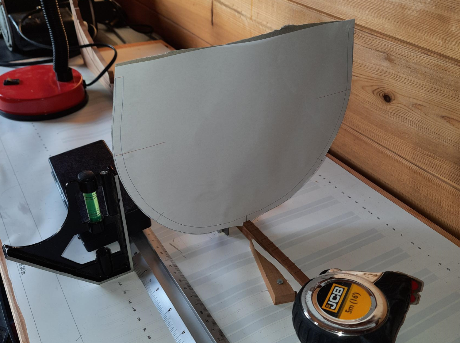
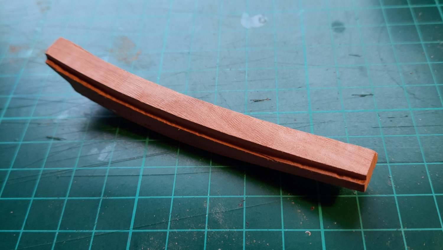
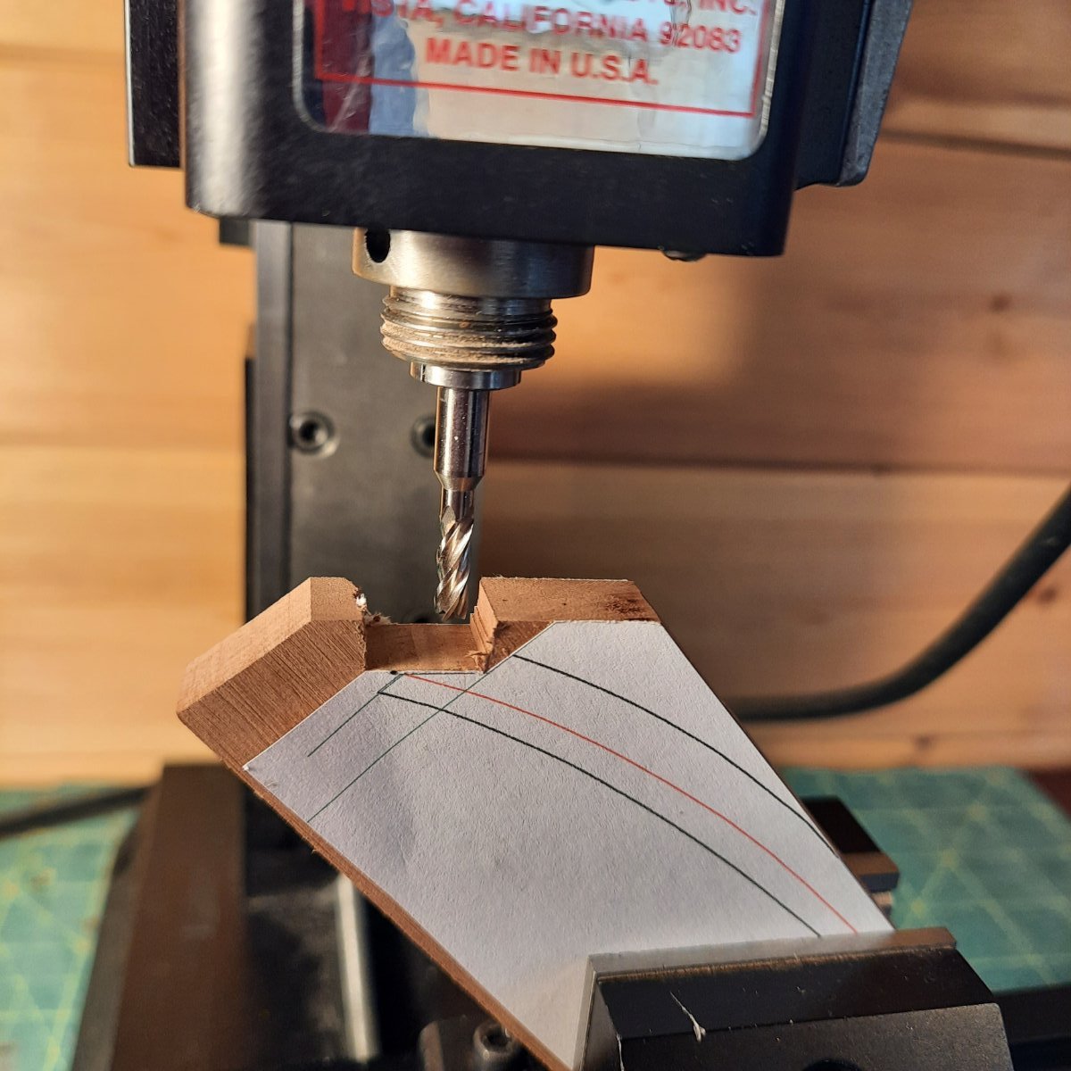
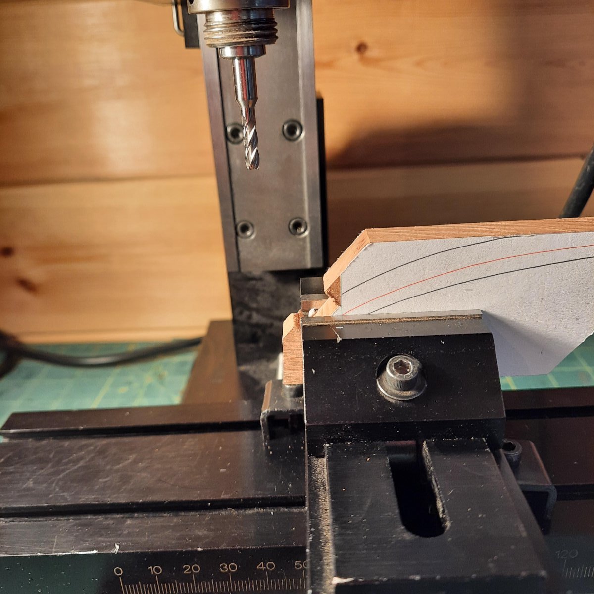
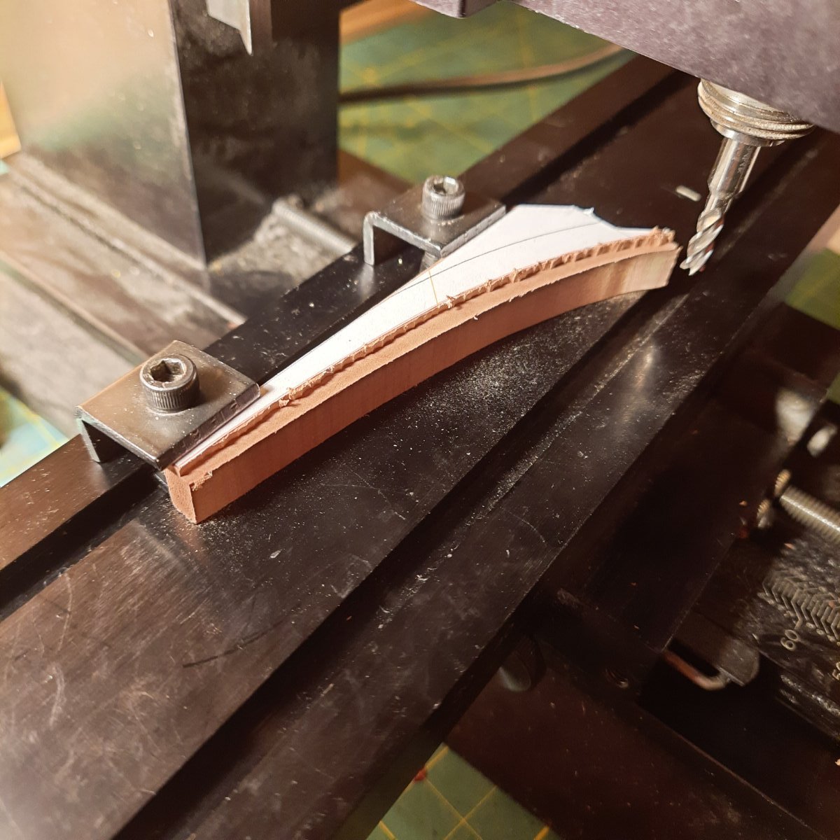
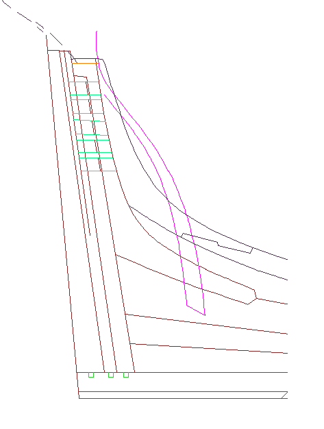
Time for an update. I have been working on the rear deadwood plans (with a question elsewhere on site) while I waited for some thicker wood stock to arrive for the lower apron. I also have had some interesting thoughts on plan accuracy. It suddenly occurred to me that I might be obsessing overly about 'correct' sizes when the reality is that as long as I use the master plan as the target for every step then any inconsistency in lower steps will be counteracted. That's not to say that being accurate isn't good it's just that it's cope able if the process is correct. So as an example lets say I misunderstood Steel (very very possible) and I made my rising wood 1mm to high! As long as when I seat my frames I use the model height of the rising wood (say 9mm (random numbers) versus the should have been 8mm) and thus make the floor depth say 29mm instead of 30mm then the problem gets ironed out. An issue would only occur should I just use plan measurements for the next piece. Hopefully that makes sense to someone. Anyway onto the next piece which is the lower apron (wood having arrived). It's not 'done' yet as this is my practice piece which I only use if by a miracle its perfect and this wasn't but only due to the last cut. For the plans I did my usual job of adding lots of helper lines, the usual orange ones indicating parallel to cut lines and the green were sighting lines to try and help line up both plans. You will notice this also needs a mirrored plan due to the ledge. This is a cut out of the full sheet which includes the other two apron pieces. One of the things I found very helpful when cutting this piece is ensuring all four sides of the blank were square (and not just two L sides which is what I usually do). This is due to the key fact that the bottom left of the apron is horizontal and flat and the three vertical lines are all at right angles to that line. Therefore I can cut my pattern and place it on the bottom of the wood blank and know I can use the sides of the blanks in the mill to allow me to accurately cut the inner of the right hand vertical cuts.. Anyway the process I ended up with was as follows. Overly detailed perhaps as ever.. 1 - Cut blanks oversize 2 - Thickness blanks to target width with thicknesser 3 - use table saw to make certain all 4 sides were both flat and at right angles to each other 4 - Add pattern to one side using the bottom left vertical and horizontal lines as the line up points 5 - Use the left vertical side as the mill base and cut out the inner of the right two vertical joints (in this practice piece I actually did this the other way round with 6 and 7 which made things harder so this is how it will happen next time) 6 - Use the table saw to cut along the big orange line (which is parallel to the face of the joint) 7 - Use the step 6 cut as the base inside the mill to allow me to mill the face of the joint 8 - Use the sc roll saw to cut along the upper edge of the apron. (Plus rough fit with fore deadwood above) 9 - Add the reverse pattern to the other side of the plan using the upper cut, and left two straights to help align. 10 - Use a scalpel to cut out the upper section of the paper pattern (above the red line) which marks the ledge position. 11 - Use the mill to cut out the depth required for the cut. Not exact here but the best procedure seemed to be to start on the right and move to the left (best sight line) and basically cut outside the line a little then slowly move it into the line. You end up with lots of tiny humps which will need smoothing out later but the key is that this gives an accurate side of the shelf. 12 - Use the scalpel to repeat step 10 but on the other side of the piece 13 - Repeat step 11 for the other side of the piece. For 11 and 13 I hit a problem with how I was holding the piece and in the test cut changing this half way through (as the clamp started interfering with the mill) adjusted the depth of cut slightly causing the last 20mm of one side to be .1-.5 mm deeper than it should be 14 - Tidy the ledge curve with a scalpel 15 - Sand the end to the correct size 16 - Dry fit with surrounding pieces to see if continuing is possible. With the test piece it dry fitted nicely on the stem and with the upper deadwood above - all three needed some tidying but nothing major from the looks of things which was a relief. So the pictures are actually with a slightly different order than above but it gives the general idea. Thanks for reading.


-
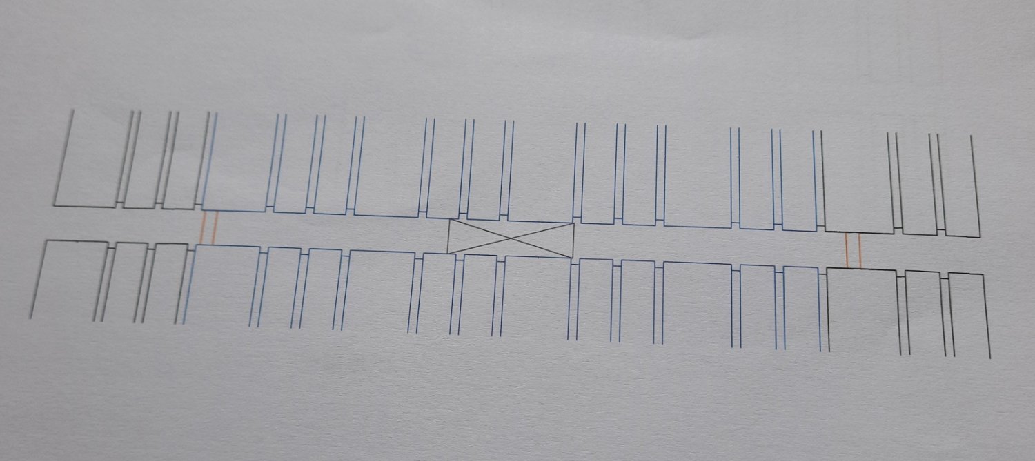
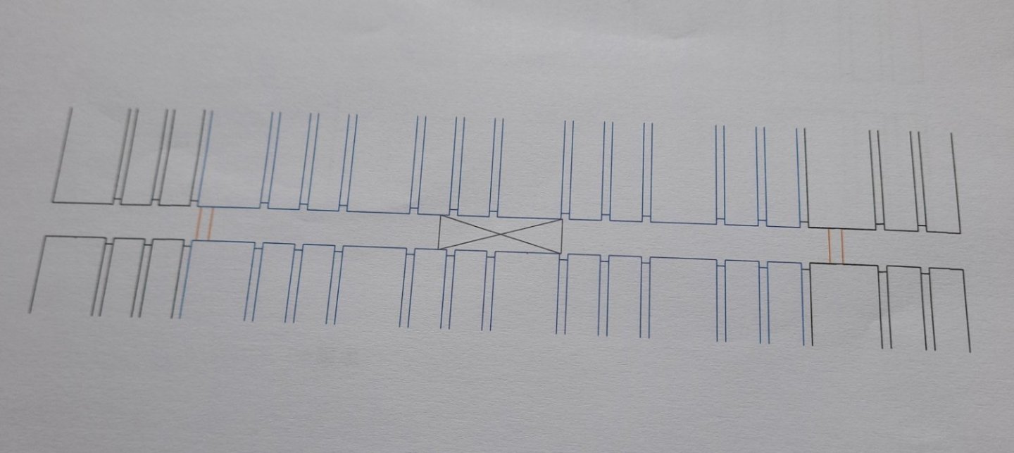
Update time. Once the vertical cuts were dealt with I briefly used some of the 'wrong' pieces to test how easy it would be to accurately cut the side cuts and rapidly decided the game wasn't worth the candle (nice old phrase that, apparently way back when prior to electricity candles were expensive so gamblers had to decide if the potential prize through playing was worth the cost of the candle (or not)to have light to play by - causing that phrase to move into the language). Anyway though I could have worked round it I decided it wasn't worth it so essentially wiped the side cuts and just cut to all the pieces to width. I then needed to cut the end butt joints and ensure they fitted well with the adjourining pieces. For this I generated 'joining templates' which consisted of the majority of a rising wood piece and the next two joints to either side. That way I could put pieces together and ensure they matched. As you can see the blue indicated the 'live' piece and the black either side adjourning pieces. One sheet was produced for each section. I also cut out the side templates (roughly) and stuck them to the pieces. This was to roughly check alignment but also so I could see from the side potentially issues as well. Things seemed good so I rapidly hit another problem (and one that Mark P had noticed when my fish plan was produced) and that was that I had not included every line I might have needed on my base plan and specifically in this case the forward mark where the keel stops. Now the rear section lies very close to the Aft Perpendicular but as its angled I was less trusting of this. So after some failed attempts to measure on the master and then use a ruler to set the keel at the correct location (never working) I then produced another throw away plan by drawing vertical lines on the master plan for all the forward keel boxing joint lines, the fore perpendicular (which was on the fish plan), the forward rising wood joints (in red) . This could then be placed on the fish plan with the fore perpendicular being the join between the two and then allowed me to place the keel exactly. I need to insert some temporary battens to hold the keel at some point soon as well. Anyway this was obviously important as the keel is the fulcrum of the entire build and the rising wood needs to be exact otherwise it would throw everything off Next up 'wood' wise I am going to glue and bolt the stem. Plans wise I am moving to the lower/upper apron and the fore deadwood.
-
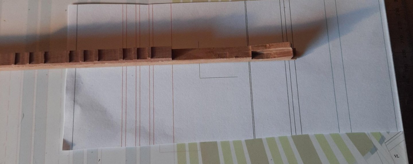
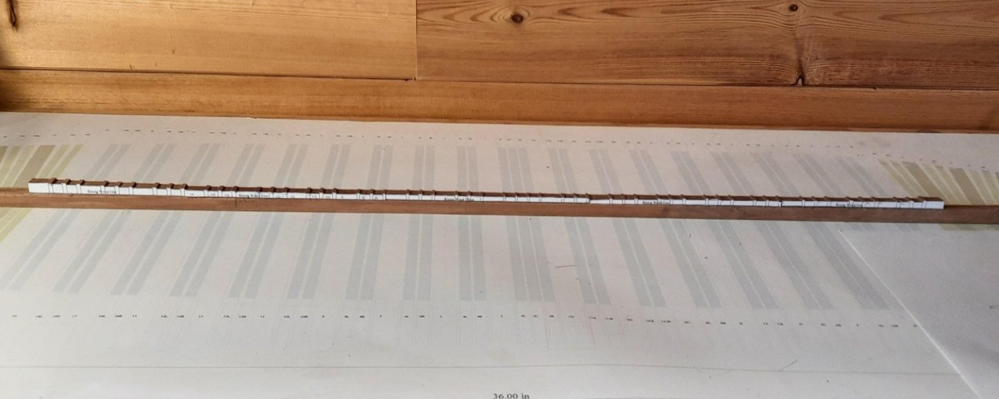
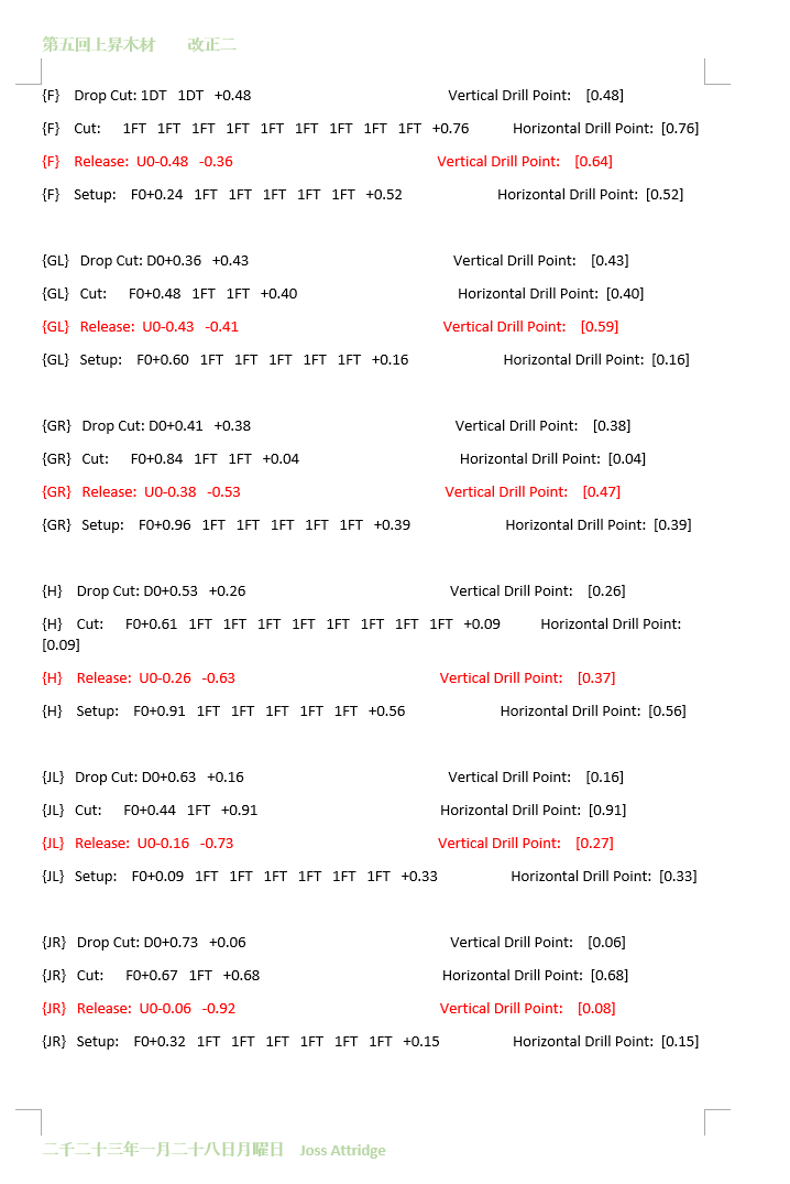
Currently cutting the top cuts with the mill and like a lot of ship building things it is proving that old quote of 'think three times, measure twice, cut once' is usually true. I rapidly hit issues due to having to do maths in my head when cutting. So let's say the horizontal axis was at 0.48 and I needed to make a cut 3.68 then ... anyway the waste of electricity and chance of mistakes were huge so after some thought I decided on a more reasoned approach. I split the stages of cuts into 4 so we have drop cut/cut/release and setup and decided the horizontal axis would be sacrosanct so at least one axis would have minimal risk of backlash. I then split the cuts into three simplified unique types - Forward to zero, Forward 1 full turn and forward by a specific amount indicated on a cut list in this way F0+0.43 1FT 1FT +0.55 would be forward to zero for 0.43, two separate full turns (so 2.43 cut so far) then forward to 0.55 (so 2.99 for that cut). For the cut and release cuts these would always use the positive axis and move forward. The vertical axis though had the drop cut moving forward and the release cut moving up (so had back to zero 1BT for 1 back turn and -0.44) . That way I could split the cut into recognisable steps that can, more importantly, be tracked. Now that is is also a lot of maths so I wrote a simple program to do the maths and produce the individual steps for me. (screen shot below, that particular cut list is for the fourth rising wood, you will note I also colour the release step in bold red as that's the point an error is more likely to occur). The program not also calculated the individual steps it also printed the end drill point on the sherline axis counters so i could also mentally evaluate the step as I was cutting it. Finally I also added incremental counters so I could show on screen the horizontal and vertical cut list so I could validate that the amounts the program thought it was cutting matched the input I wanted it to cut. The nice thing about this approach is that it simplified the methodology. I would start on a piece, go to turbo cad with a handy sheet of A4. Write D/C/R/S and then measure off the plan each cut directly. Once done transfer the totals into the application adding the expected start wood depth and the start height and run the app. Once finished I would validate the horizontal and vertical cuts were as expected then print them off. Now the actual cutting. I used a 4mm end mill - I tried the 6mm as the largest mill to fit the gaps but found this had a tendency to damage the wood or at least cause excess weird shavings... The 4mm seemed a good compromise between cutting and not being so thin as to be influenced by the wood it was cutting into. When cutting I carried out each step in the cut chart and then crossed it out with a pencil before carrying out another. I also restricted any cut to 2mm max (so a 2.16 cut would be a single cut of 2 followed by a cut of 0.16). This was protection in the larger cuts of wood damage or losing alignment. I also found the end mill mush preferred cutting into the wood from the direction closest to me as opposed to scooping it out from the end closest to the mill base ( logical really when it approaches from 'my' side the drill cuts a relatively even amount of material, when from the other side it starts with a very light cut the gets progressively deeper - whether that's true or not I don't know but I found cutting this way made for cleaner cuts with less mill complaining). This meant I had to carry out a cut then return the mill to its start point as I set up the next. Usually I also pulled the mill away from the wood to set up the next cut with one important exception which was the drop cuts which I tried to setup half on and half off the wood. This is because the drop cuts usually occur after the tiny 'steps' and this way reduced the risk of those steps (some as small as 1.36mm wide) being damaged.. Anyway apart from the cut list no nice pictures here and only a technical description. I am almost done with these top cuts then have to think about the best way to do the sides...
-
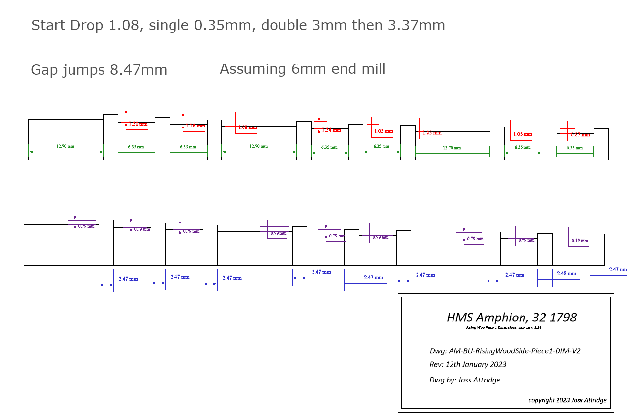
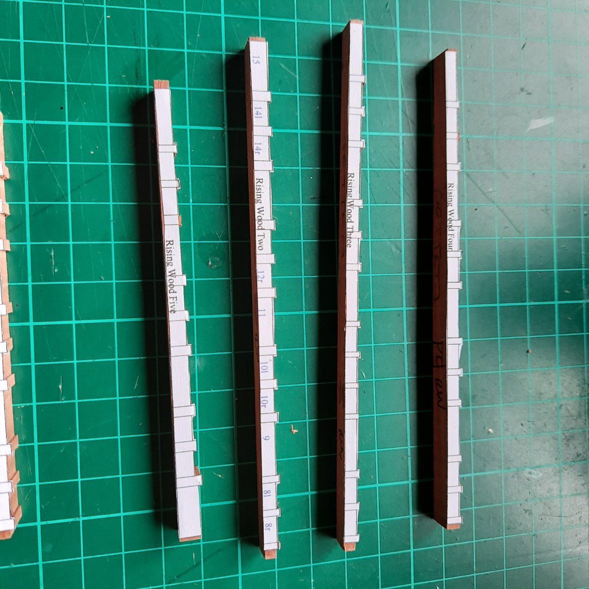
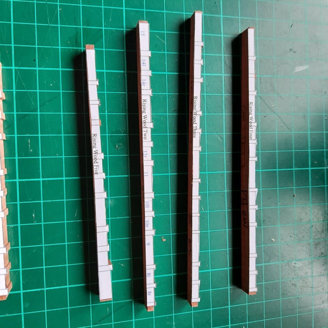
Thanks for the comments all.. Now for a brief digression onto rising wood planning. For some reason I am using the turbocad structure better to simplify the plans. As an example looking at my existing rising wood plan I would have previously put the measurements on each section making it somewhat confusing to read. After trying (taking my piece 1 as an example, the rear piece) copied it 5 times and then split the measurements over those 5 colour coding to differentiate better between vertical and horizontal as can be seen below. I then started on my cut plan and realised even that was excessive and I could just concentrate on those measurements which would need cutting. I could then change the print scale to 2.5:1 so it was much bigger and get all the relevant measurements in two copies. Piece 1 is the smallest piece and I have enough wood to start producing some testing pieces to work out how I want to cut it. You can also see I am retaining my plan to simplify the piece by removing the horizontal angle and replacing with a straight edge.