
My Fathers Son
-
Posts
259 -
Joined
-
Last visited
Content Type
Profiles
Forums
Gallery
Events
Everything posted by My Fathers Son
-
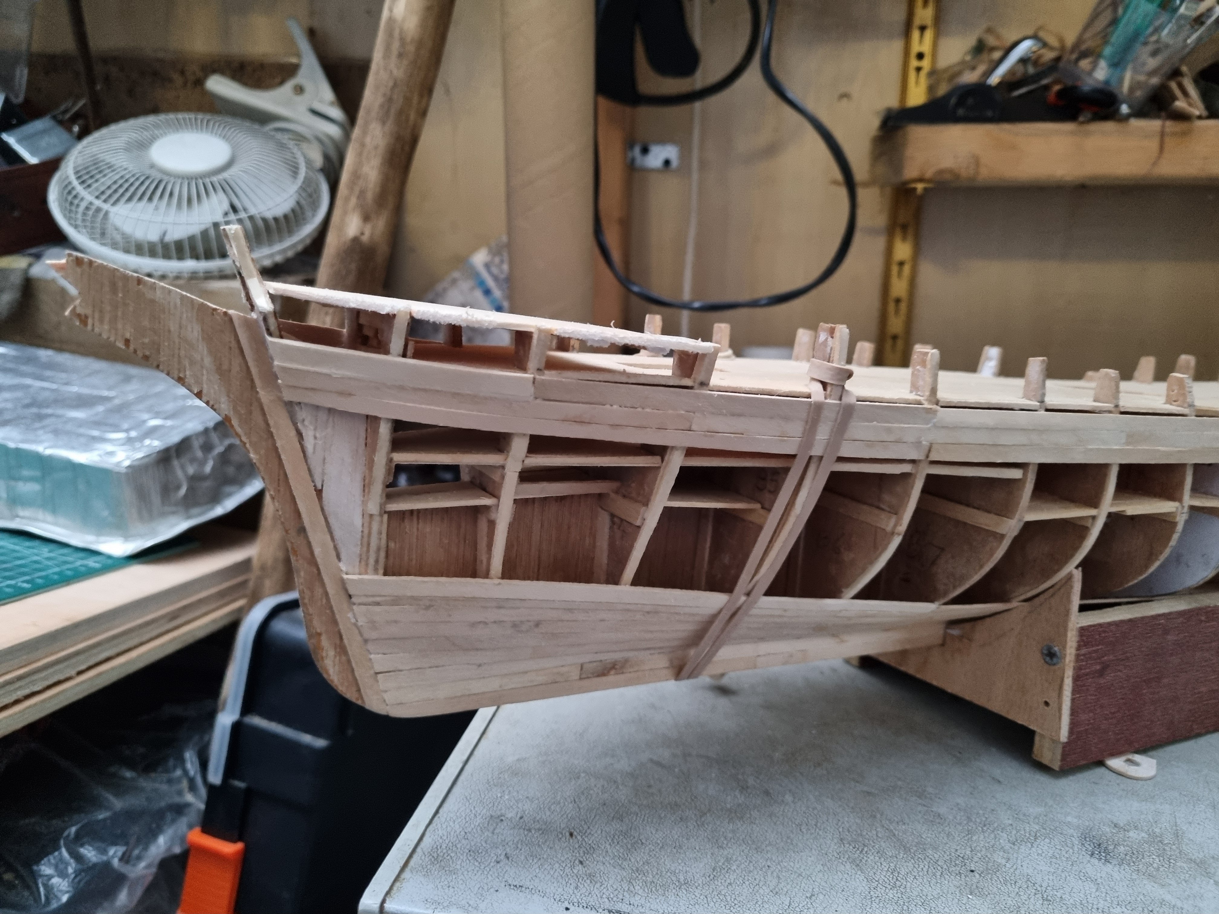
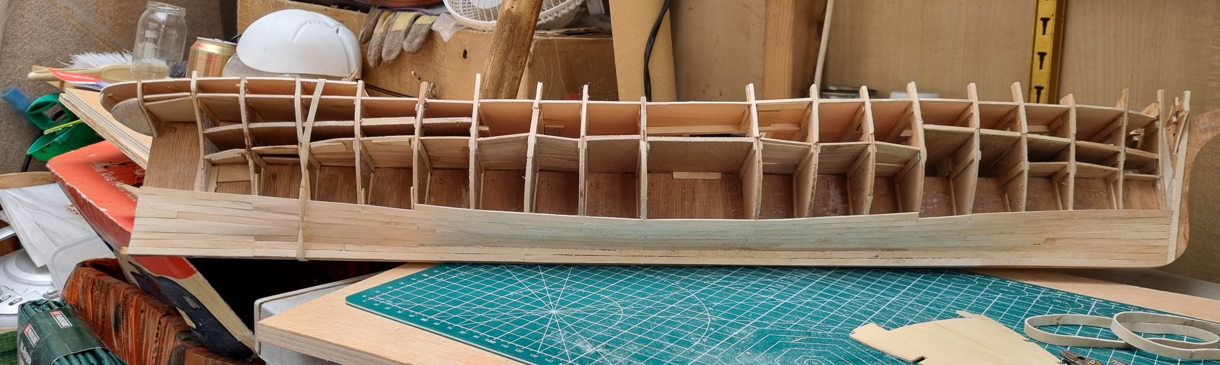
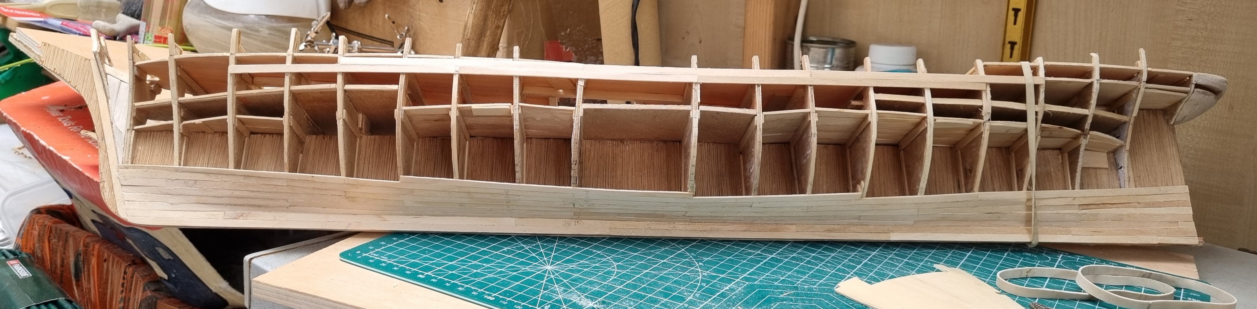
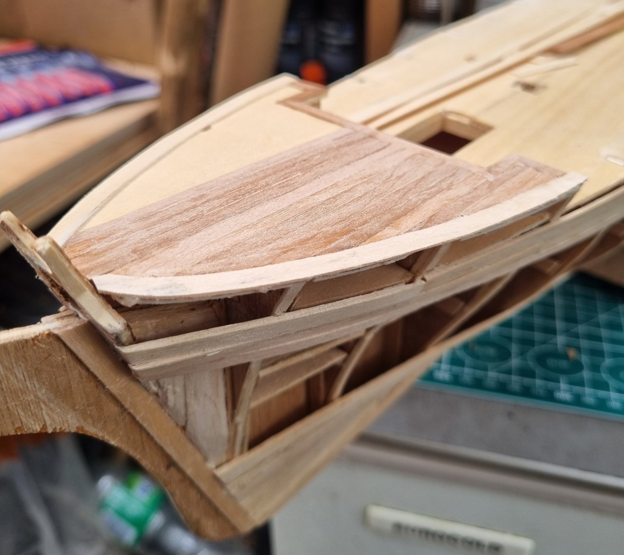
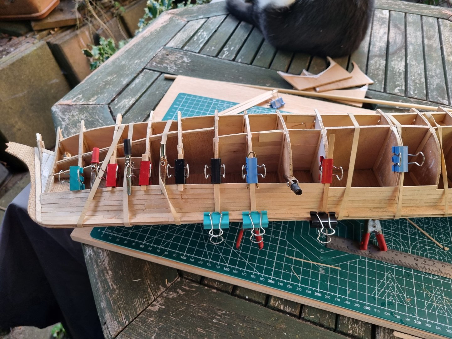
I started from strikes 3, 4 and 5 from stem to stern. There is no tapering on these strikes. The fore section is a gentle curve into the knighthood. Aft is another story. Still very little tapering but there are compound twist and curve. The later section had to use hot water to soften the basswood and this has given me a result I am content with. The top strake is no 2 and is not glued yet, i am just gentle persuading it that it might like to become that shape. The Basswood strip behaves quite well in these circumstances. I did intend to put no 1 strake on to forn the shape but I think I will leave that till tomorrow, I am on the late shift for today and tomorrow so won't get much if any done tonight. simon

-
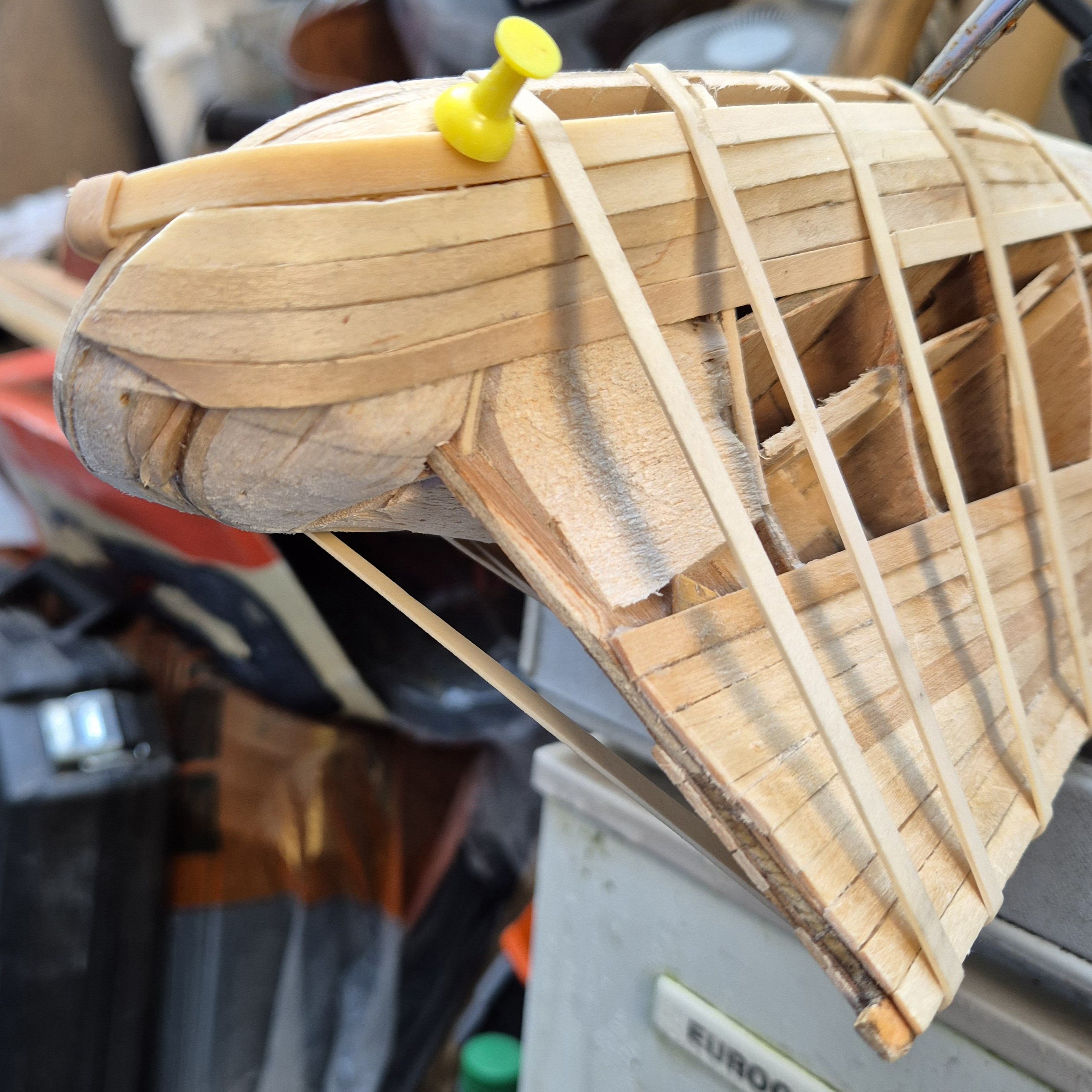
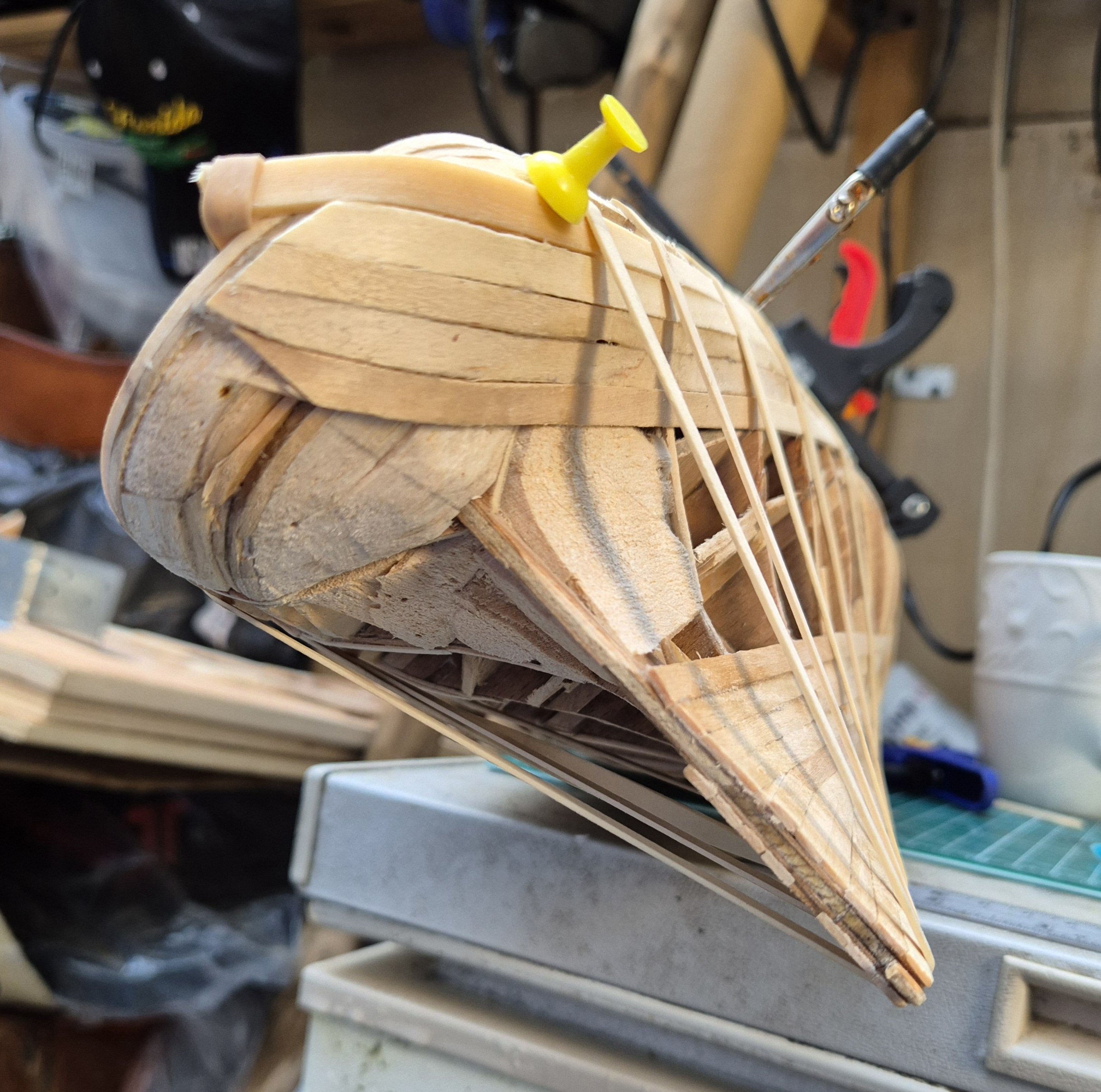
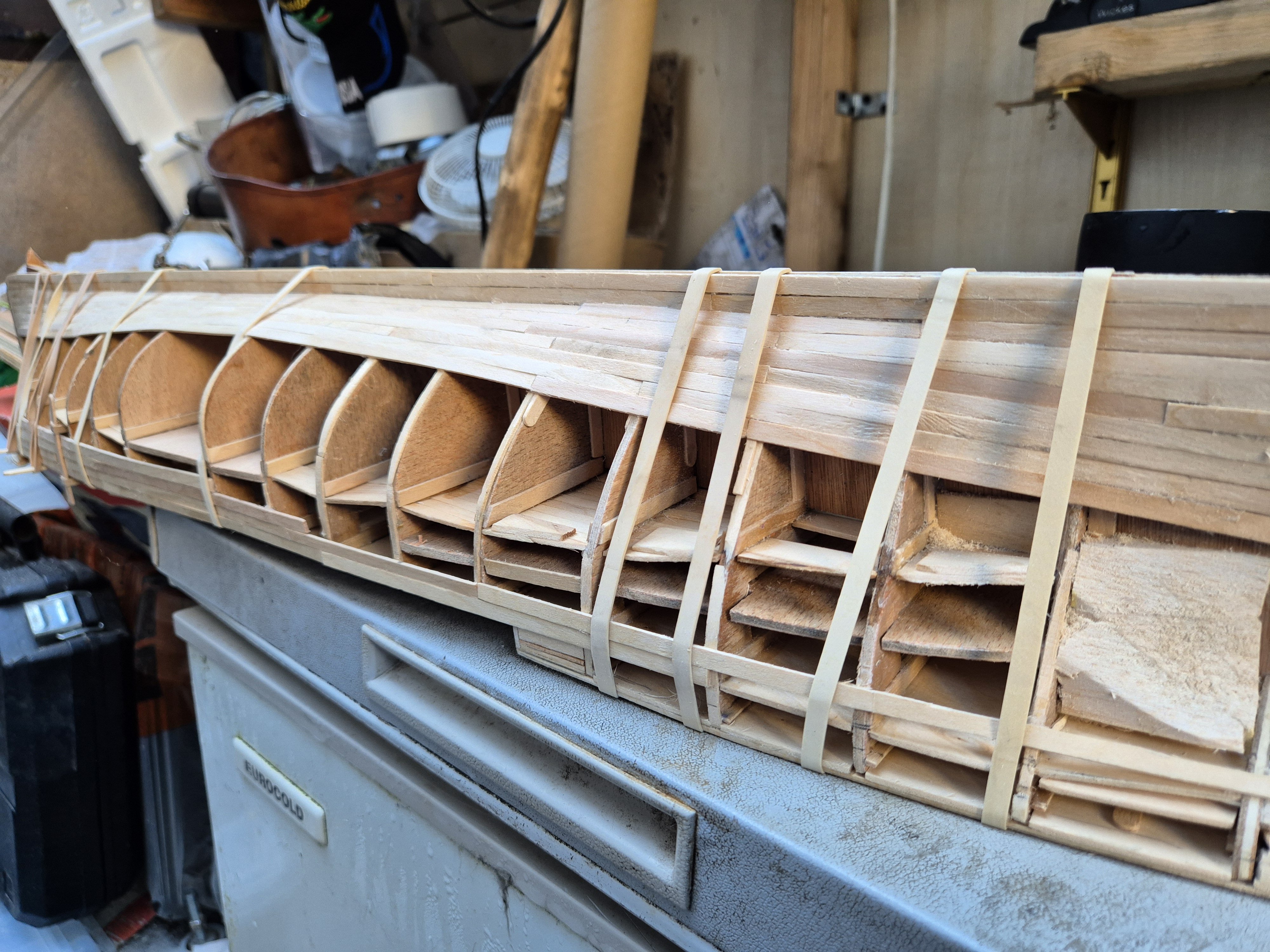
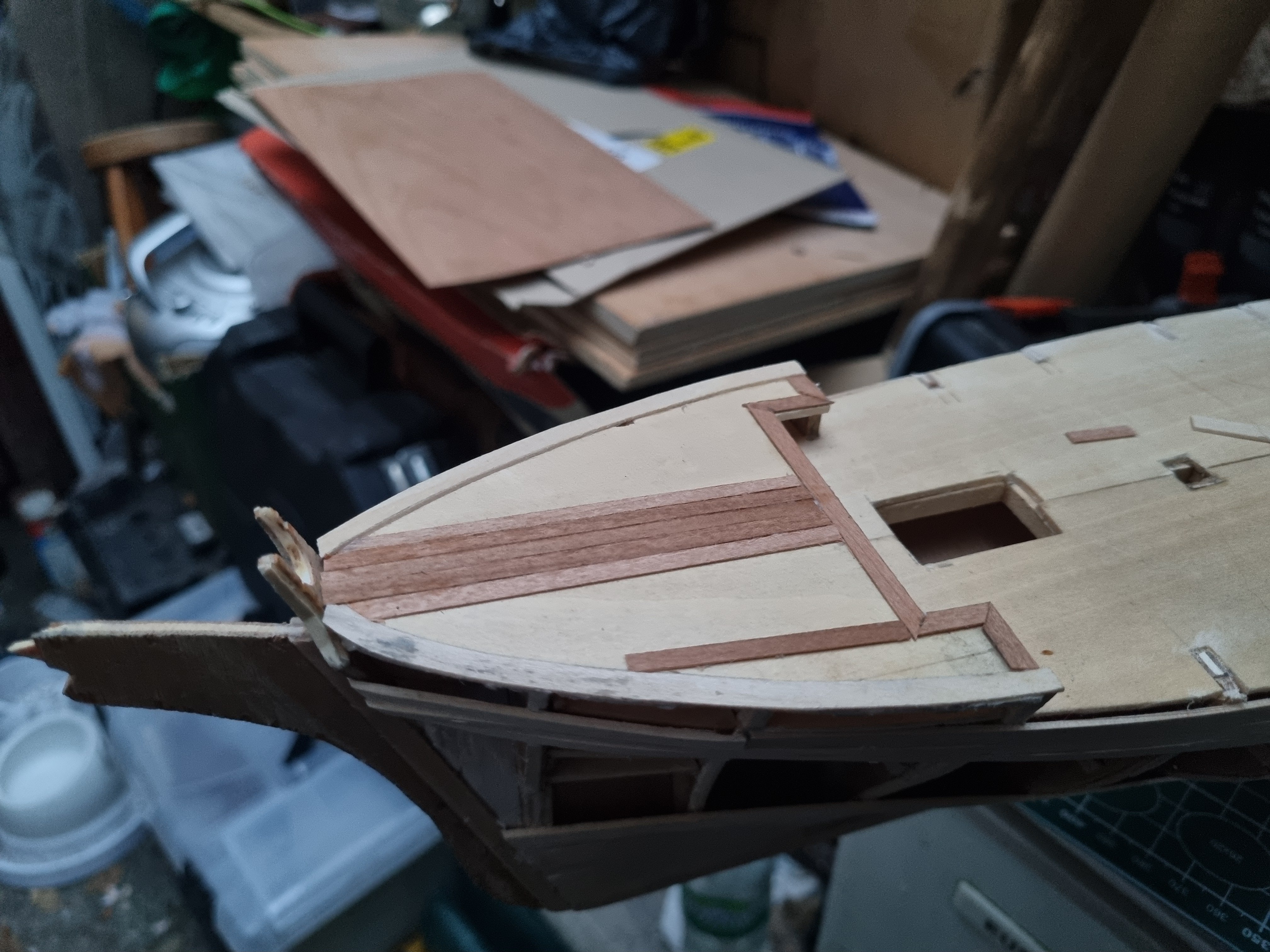
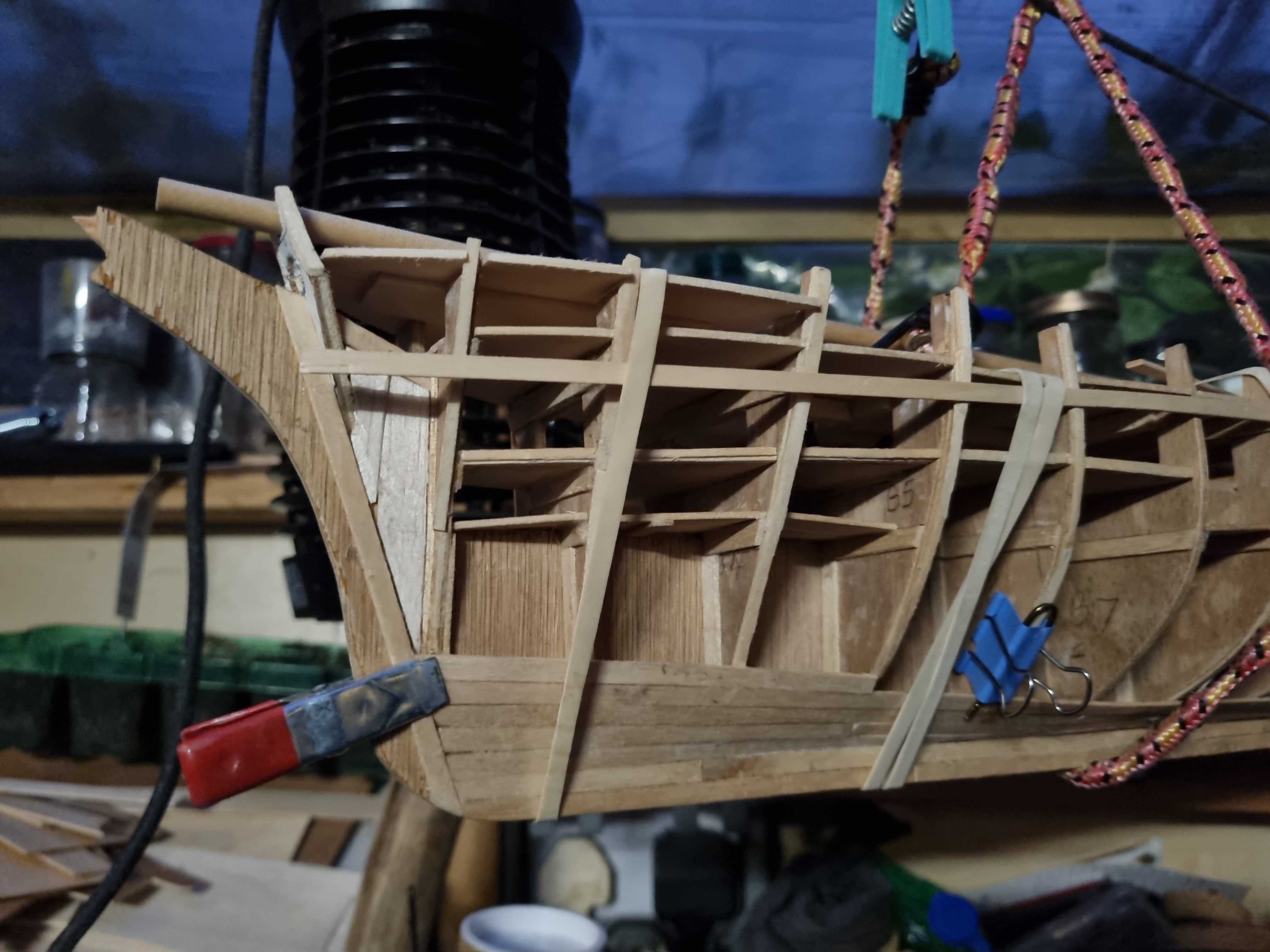
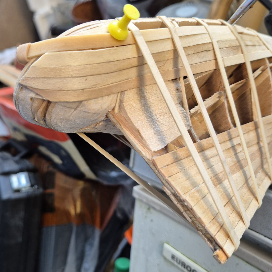
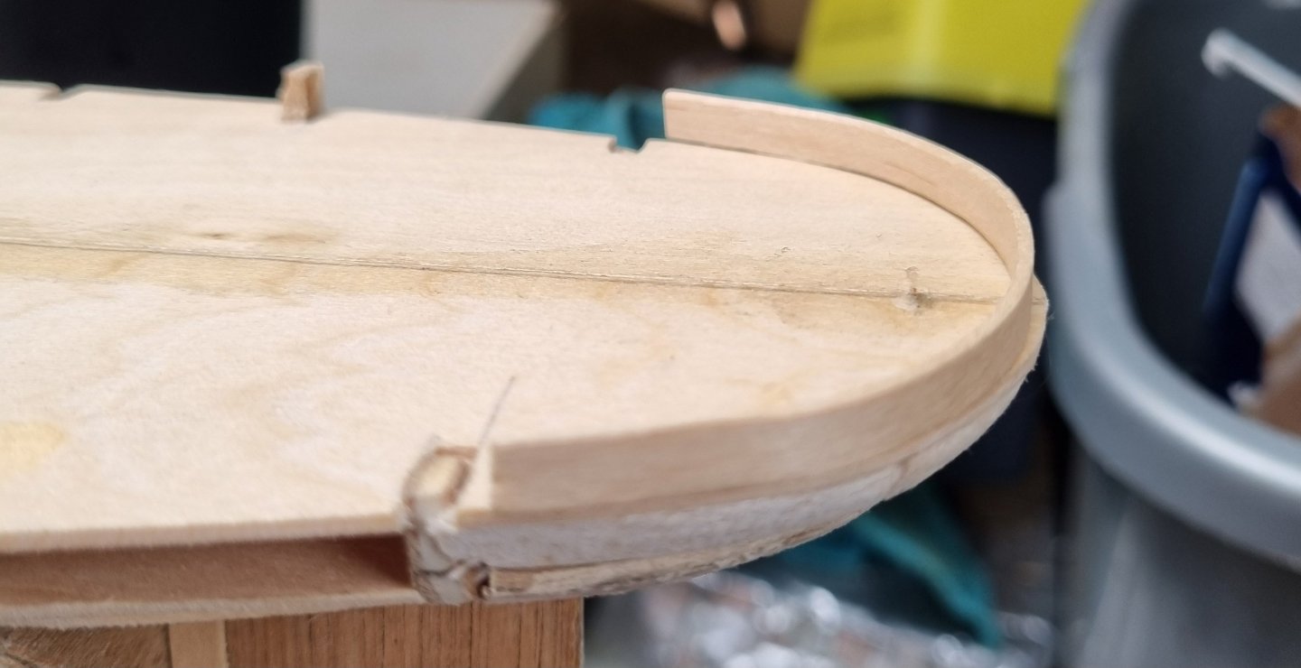
Have been wearing the old thinking cap trying to figure out how i am going to plank the stern. One piece in and it was a son of a gun to get it to stick. I havent had to steam or soak any timbers till now but i have come to the conclusion that this has to change or i am not going to get the finish i want. Also, getting clamps on that last corner is next to impossible and had to resort to the universal clamp, a rubber band, or in this case, multiple rybber bands. There were two pieces here but one broke and i removed it. Also, you can see that I had to fill the void where the transition is the most complex curve, this will be a good test of my patience. The rest of the planking is coming along but I am not rushing this. There are a couple of places where I will overlay some 1/32 basswood and apply judicious sanding. I am not aiming for a perfect finish. I want to be able to see individual planks through the paint. Going to have to start shopping for accessories such as portholes, blocks and deadeyes soon. Simon


-
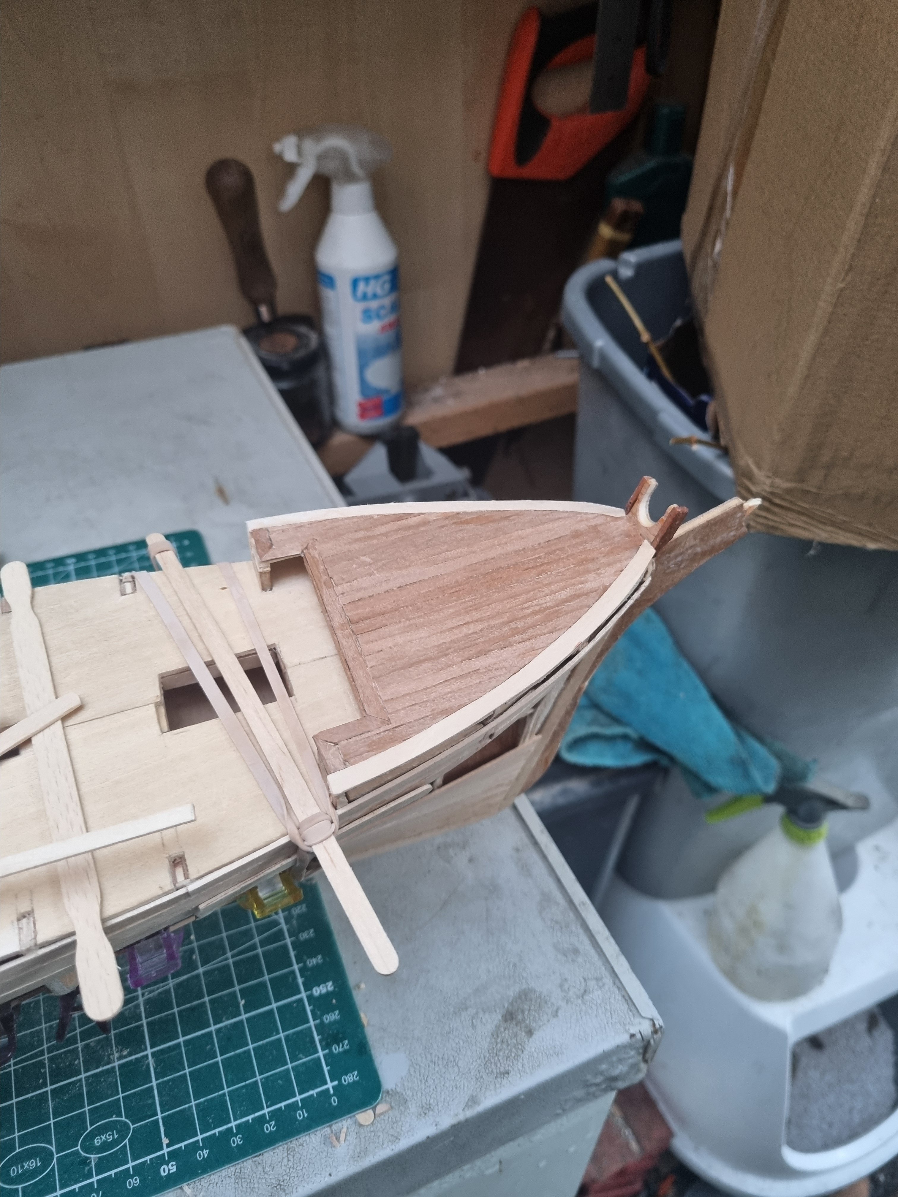
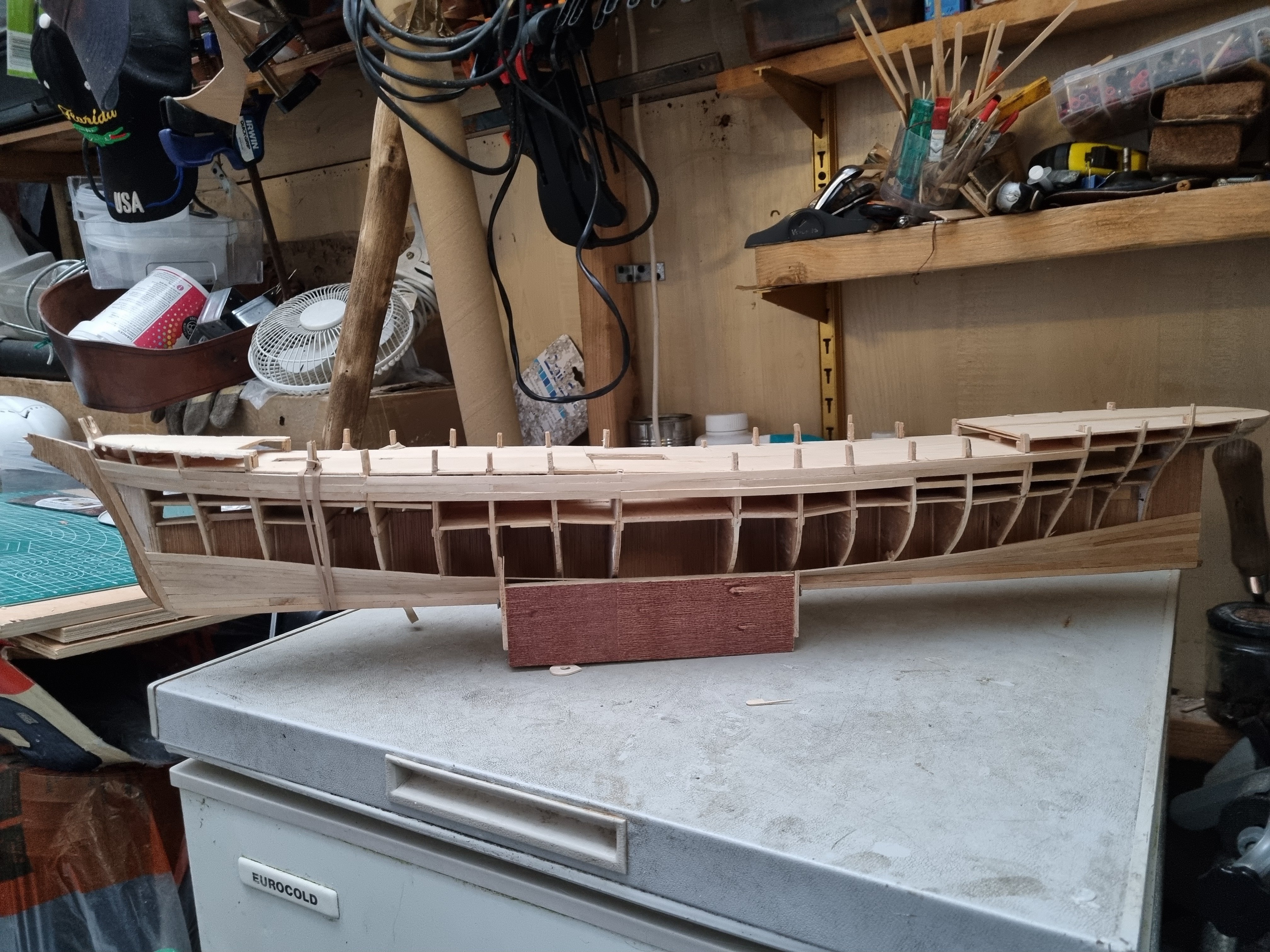
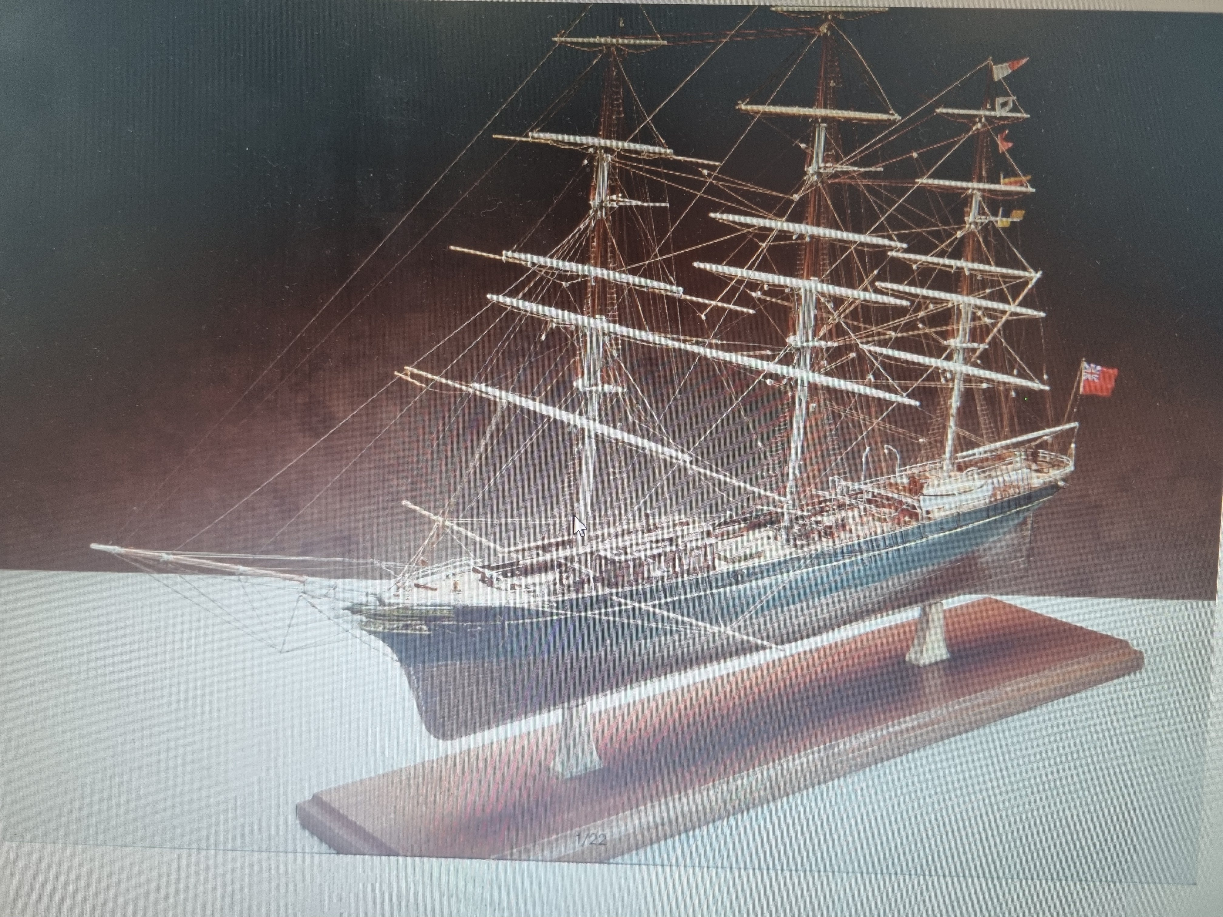
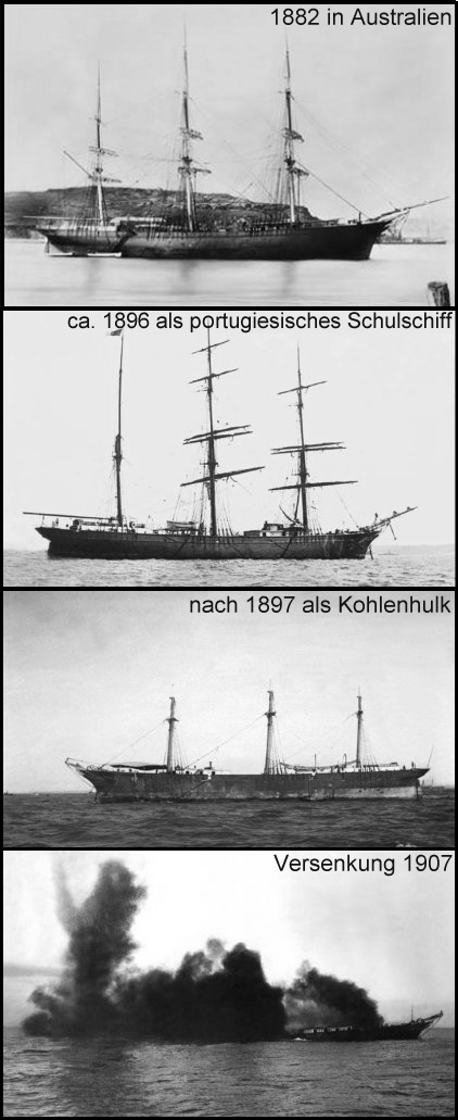
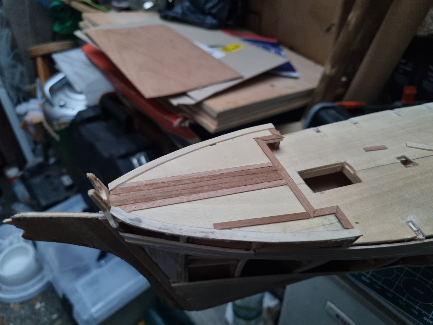
Nor much progress the last few days. Had to correct three strikes on the starboard side as they were out of alignment. Fine tuned the frames adjacent to the stern deck ready for planking and started marking out where the aft deckhouse is to be located. Rough it out on FreeCAD and transfer to a card template. Once I am happy with the layout, I can transfer this to the actual deck. This morning I have been using up my supply of coffee sticks advancing the hull planking on the Starboard side and looking at how I will be planking the stern. You can see from these images that the gunwales are not flush with the aft deck. Rather a sad ending for the old girl. The 1937 model has gunwales about 50% up of the height of the aft deckhouse so i will emulate that and compare to the 1896 profile above to see if it makes sense. Simon
.jpeg.32df40942063b4d33e2b0cc31298f1eb.jpeg)
-
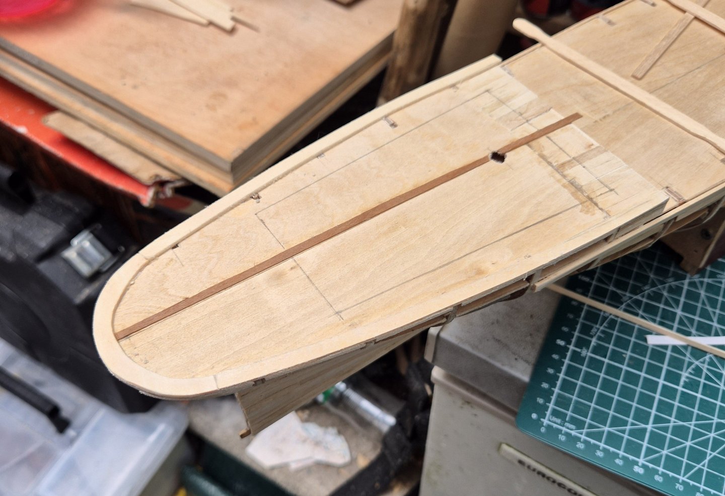
Thank you guys for the likes and comments, the veneer cuts easily and the prep work on the deck paid off. I have measured her today and let's keep it metric to make it easier for all. She is 720mm between perpendiculars, 125mm across the beam and 100mm from the main deck to the foot of the keel midships. I am not sure we're the draft is measured from but the gunwhales will be 15mm from the main deck. So from gunwhales to keel she will be 115mm. 212ft is 63.6 metres which at 1:95 should be 670mm. So the actual scale is about 1:88 Beam is reported at 36ft so 10.89m. At 1:88 that should be 12.37cm so at 125 that is pretty much on the mark. Depth of 6.4m or 20.9ft is 7.2cm, but I am not sure where that is measured from. That might account for her sleak lines. Simon
-
Forgot to mention I finished planking the forecastle. Simon

-
K7 It's the Admirals birthday tomorrow so I might not get the chance to look at this in detail. I did a rough and ready calculation this evening and the beam seems to be in proportion with the length. I will take some physical measurements and post them soon. According to the plans, it is 764mm between perpendicular but I will have to check. Simon
-
I have just checked by dimensions and think I might have made a boo boo. T was 6" shorter than CS at 215 ft. My model is 32" in length. That is Not 1:96, more like 1:75. Do'h. I will have to check the beam before I go any further. Simon
-
Just a little bit of planking while waiting. Simon
-
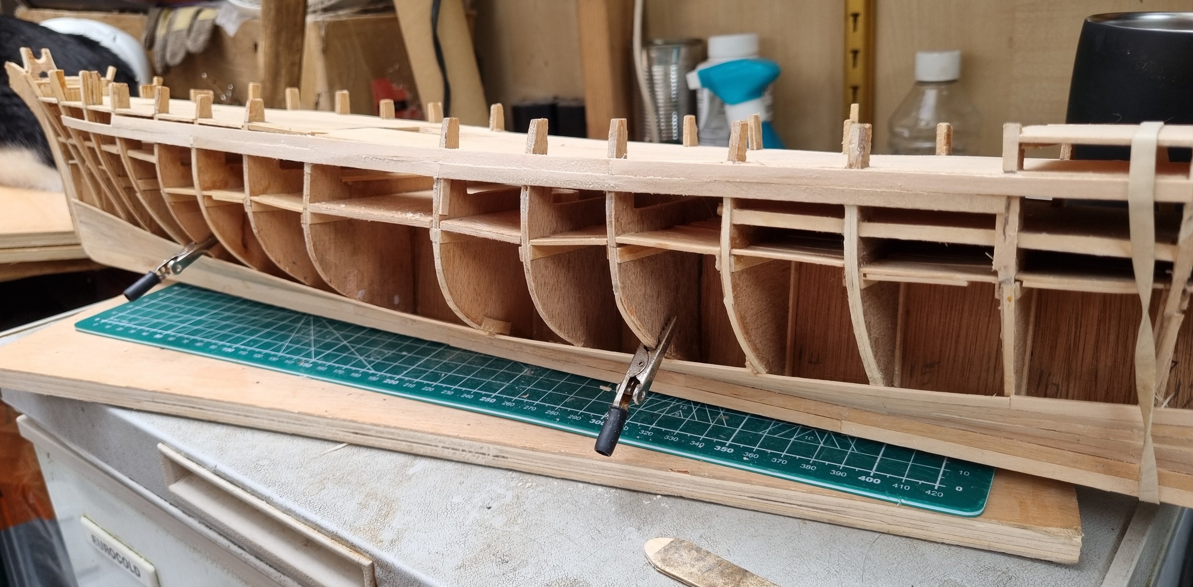
So work was early start late finish today but dinner is over a d I am enjoying the cool evening on the edge of outside. I am short of planks now and will have to replenish my supply of coffee sticks. In the mean time I have trimmed of the tops of the frames flush with the deck. I can then run channels around the perimeter of the decks. The forecastle is done and I have edged and laid a few centred deck planks in Cherry vaneer. I won't be edging the planks, at this scale I don't think it appropriate . I am losing the light and it's been a tiring day so will be putting her away for the evening now. Simon


-
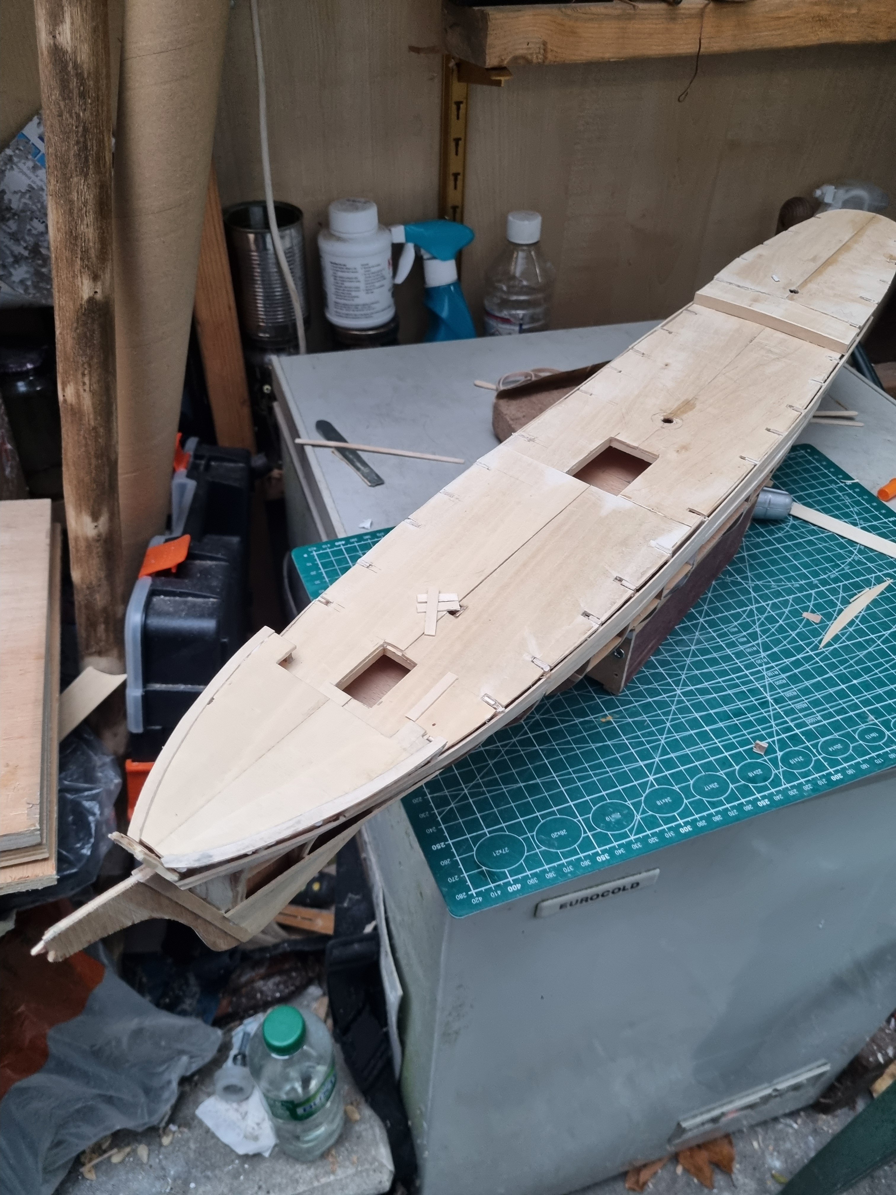
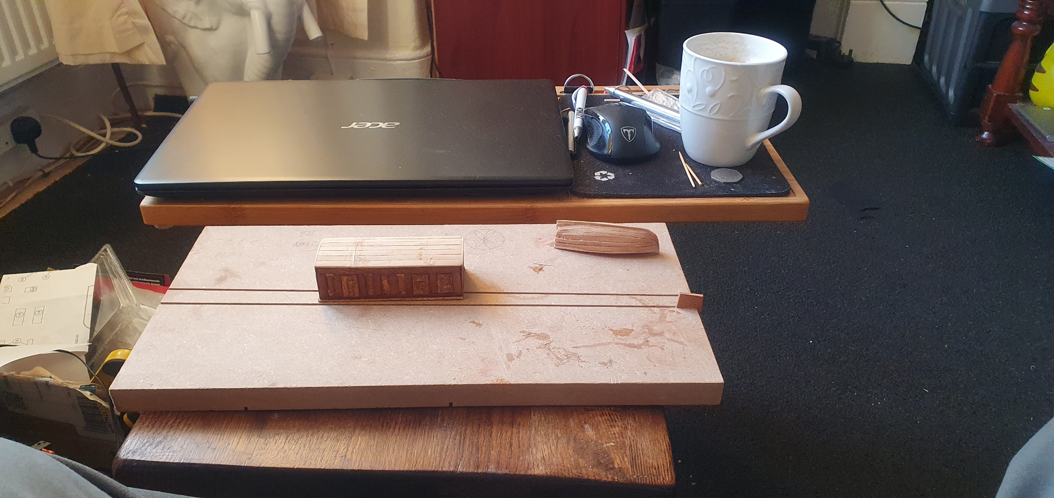
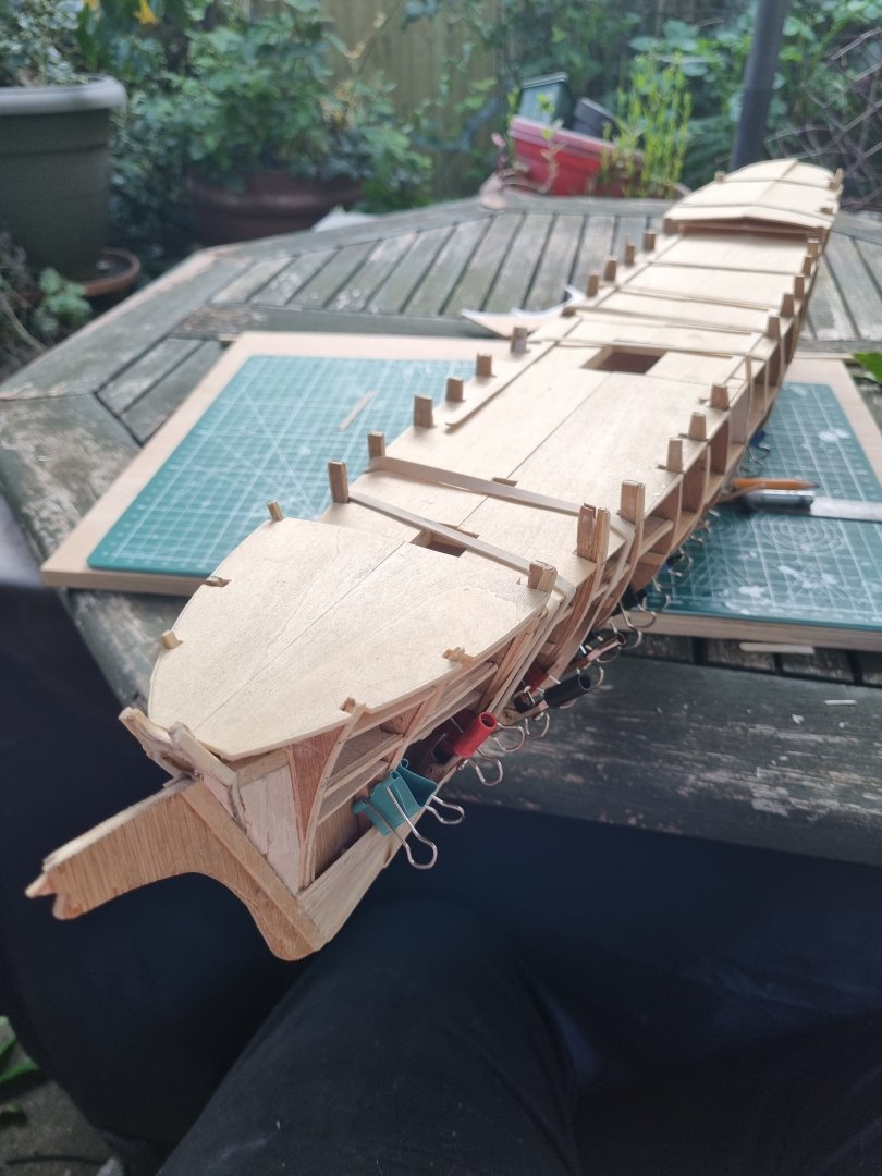
Still working on planking but thought I would just post a couple of images of T so you can see where I am at. That yaught profile. Both sides are equal in progress. Forecastle is locked in, just sanding to the final shape. Temporary stand just to sit her on while working on her. Simon


-
Hi Rob, Thank you for your comments, I certainly would not just disregard the Antique model, as you say, the maker had significant skills. I also get the point about timeliness, T like CS went through changes over the time of service, both ending their working days rigged as Barques. When built, I don't believe either had stunsails, both improved on sailing times so expect these were installed in the early 70's. My plan, such as it is, is for CS and T to both be on display in my living room but that was as far as it goes. If I were to choose a date, if I did, the most reliable time would be the period were I actually have drawings of her deck plan. However, those plans are not the best quality image wise and just blowing them up does not improve things. There are a few photo's and paintings but for some reason the artist prefers to depict her from the front quarter with sails straining in the wind instead of convenient overhead views of the deck. The nature of the gunwhales prohibits sight of the deck when pictures were taken in side profile. The deck plans I have set out the basics but say nothing of essentials such as the chicken coup nor is there any reference to a pig pen. Voyages of 100+ days would make the provision of fresh meat essential. Also. With only one deck house forward, we're are the crews quarters. Perhaps that is why the forecastle is walled in with a door. Hume's model has the anchor chain run almost the full length of the main deck. The damage to her wooden deck, not to mention the risk to sailors when the chain is deployed would be horrendous. But lifting that anchor without a windlass would be impossible and it has to go somewhere up forward. CS had bunks deep inside the forecastle, perhaps T did as well or on the deck below. As much as I want to make an accurate model, I think I might have to be like a journalist rather than an historian, and not let the facts, or lack thereof, get in the way of a fair model that is a reasonable facsimile of T. I know this approach is not the preference of everyone but I hope to create a model that stretches my ability, is aesthetically pleasing and to people who can tell the difference is recognisable as T. If, and I sincerely doubt it, I get anywhere near as accurate and pleasing to the eye as your Glory, I will be proud as punch, and in truth, I would love to be able to do that. By the way, I enjoyed your piece on the representation of detail pertaining to scale in your blog, I agree that it is better to use less detail and do it well than to go to far and do it poorly. Of course if you can do that detail and do it well, such as Cyril Hume's barrel! Simon
-
I don't know about good set, I used Cambells drawings, as these are reputed to be fairly reliable. I am also more likely to follow Hume's model, I read that he interviewed former sailors who served aboard her. As good as the Antique model is concerned, I don't know what the provenance is and there are significant differences where Cambells plans and Hulmes model have things in common. The all green model in the museum was made circa 1900, at that time she was re rigged as a barque and tramping around Africa. The builders prototype only has one image and you can't see the deck, but what you can see is missing key details, was probably done deliberately to make the deck seem bigger and uncluttered. So time to start comparing images to plans. Simon
-
No, and the fore castle is walled with a central door and hatch over. No knighthead in the Antique either.
-
Hi Rob, Not sure, but that is a much better than the one that I can find at the moment. The only thing I can find is at emuseum.aberdeencity.gov.uk/objects/27267Thermopylae-clipper-ship The images there are of a rather crude model simply rigged with boats that are completely out of scale. There is a prototype model object number 13563 which is what I was originally thinking of. The virtual tour of Aberdeen Maritime Museum only seem to have Ariel. I will have to wait till I get home and look on my PC. The above pics are of a much more skilled modeller. There are some nice paintings on Doric columns and a couple of photos as well. Also, powerhouse collection have Cyril Humes model which I would presume to be reasonably accurate. Many thanks for the update and images. Simon

-
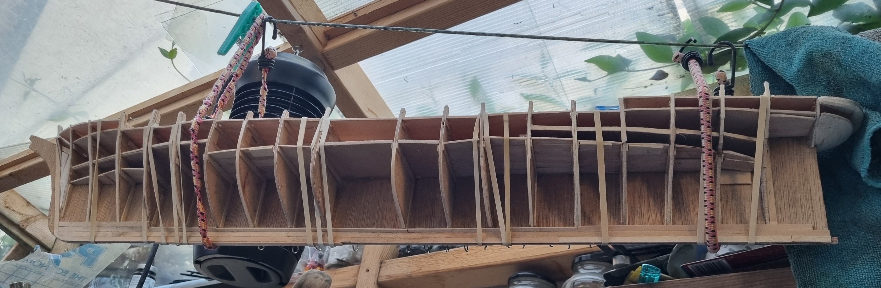
John, I have seen this image of that model and the builders model in the museum in Aberdeen, I think, don't quote me, and these images are informing my model. I had noticed that the chain lockers were set a long way back. Whilst I am doing my best to produce a ship recognisable as Thermopylae, I don't have the skill levels of Mr Hulme nor 8000 hours. The skill to make, shape and assemble a barrel 8mm high in individual saves and metal rings is, well I am lost for words, incredible. I won't be using my hair for rigging material, there are no lines on her that short, and I need to keep the little I still have. I am on strake 7 on both port and starboard sides, on the port side Also on the port side I have started the top two rails so that the uppermost 4 or 5 strakes will be a full run from stem to stern. I have steamed a single strake for the gunwhales around that curved stern but I have to admit that I am not looking forward to that section. I am not finding planking difficult at this scale, just slow and it is hard to see progress when the sides only increase in size by 5mm per strake. My inventory of coffee stirrers is dwindling, and my usual source has changed the spec on their supplies. I have about 60 left. Each strake uses 4 and I have at least 14 strakes on each side to complete. That's at least 112 and does not allow for recuts. I think I need another Coffee. Simon


-
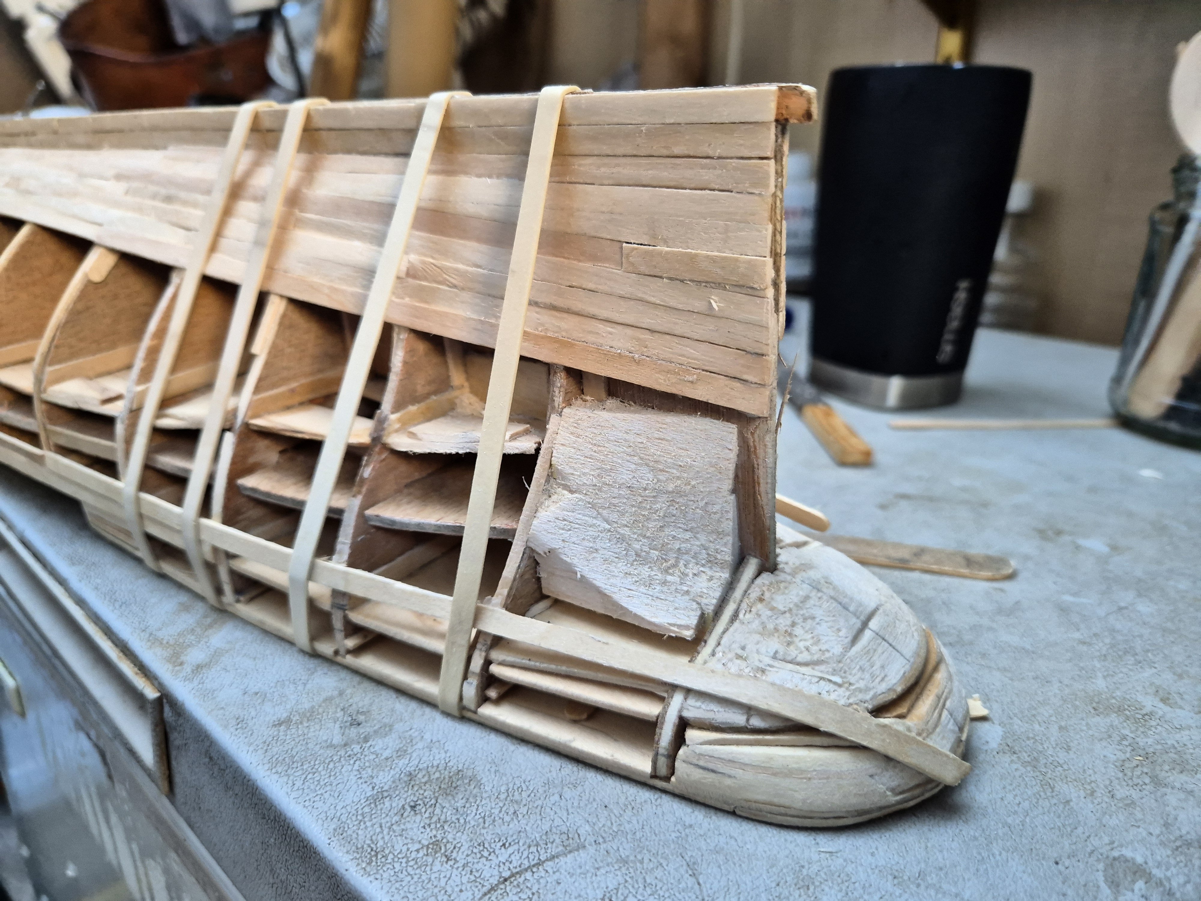
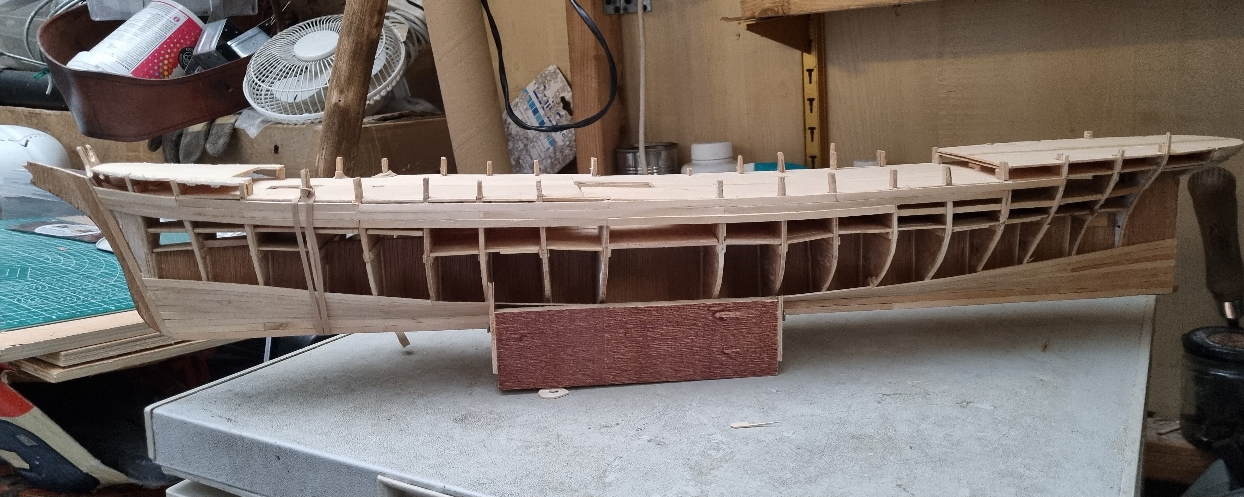
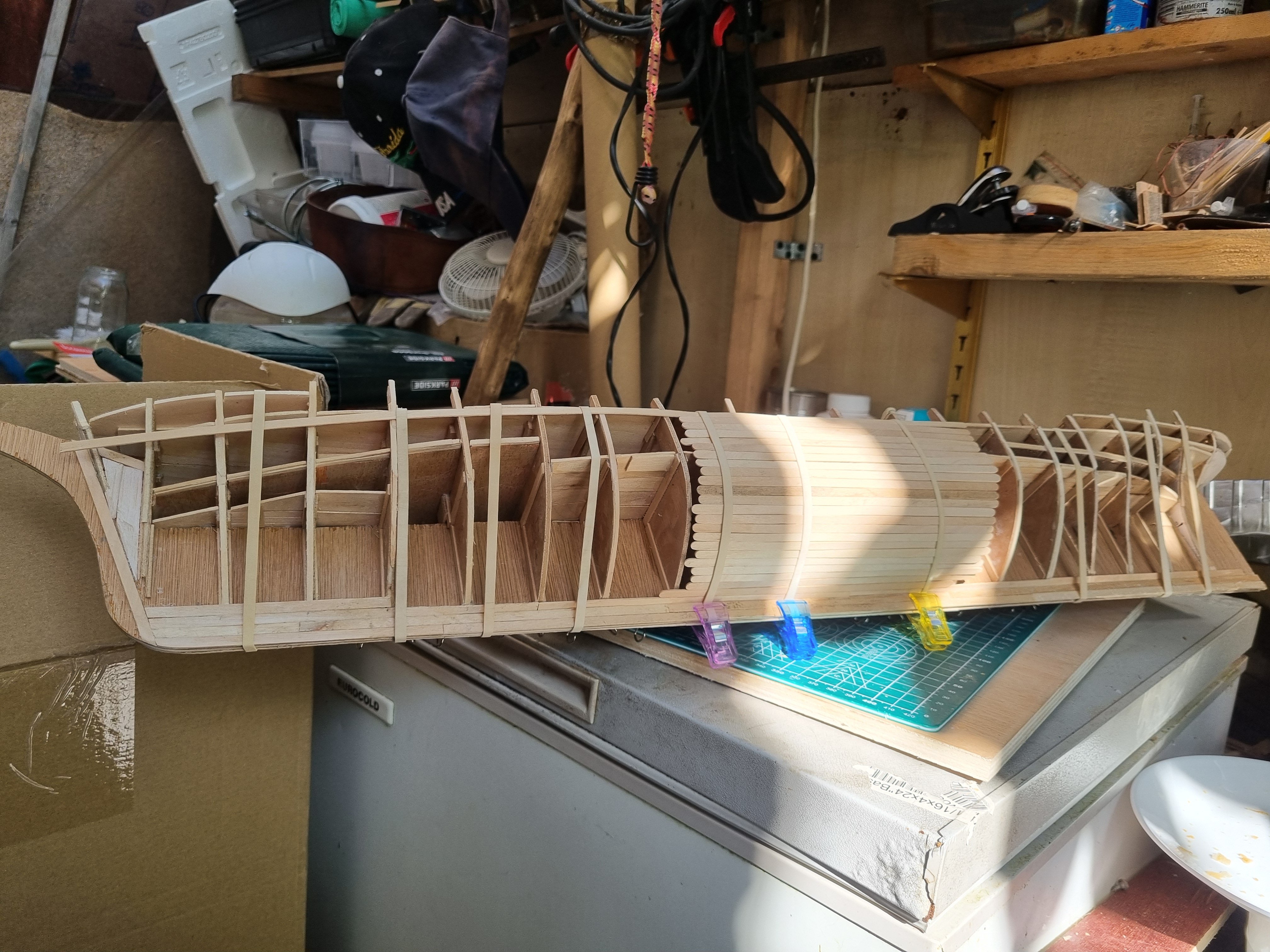
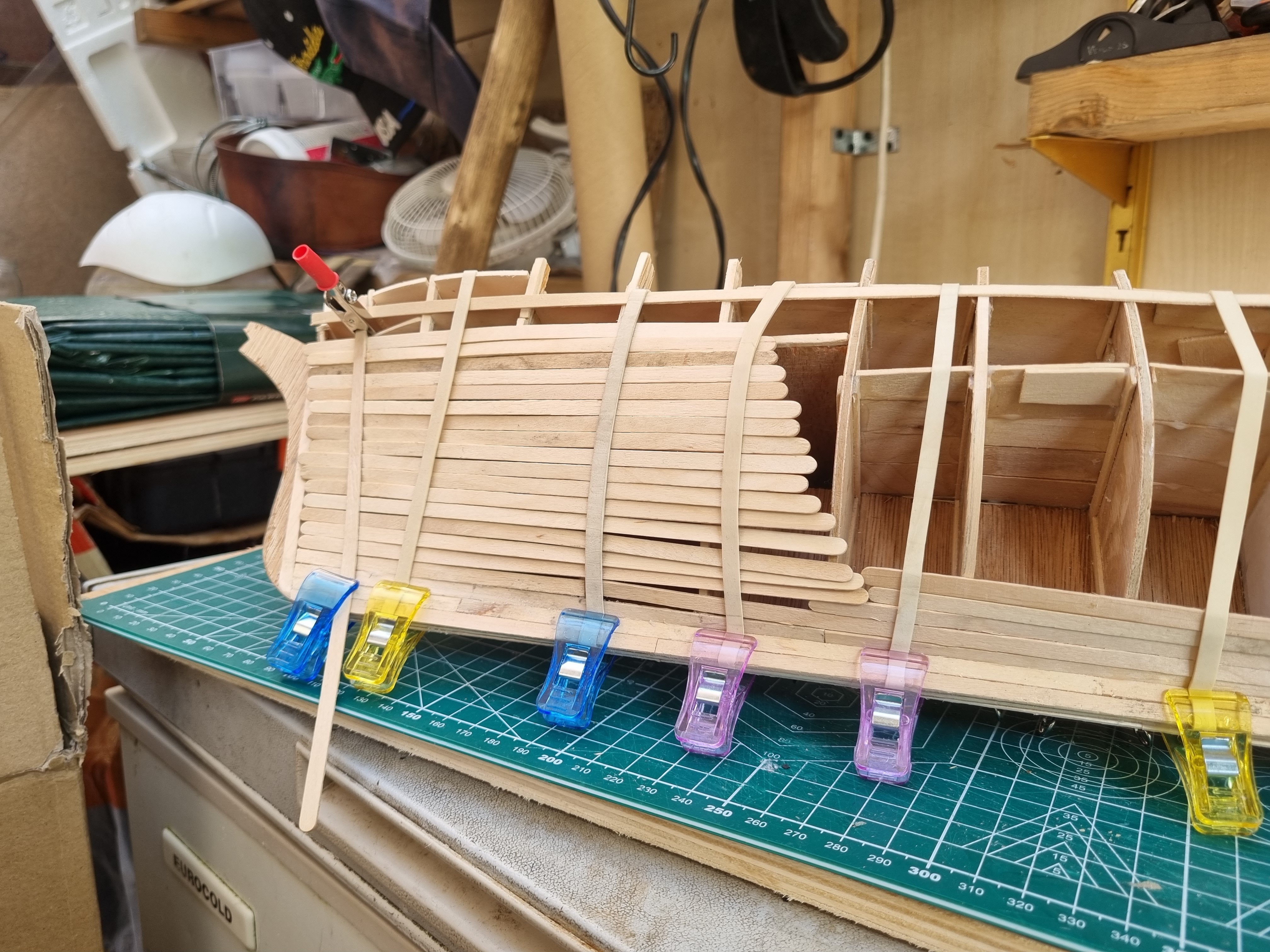
Yeah, warships are not for me. Don't get me wrong, a visit to Portsmouth and drool over Warrior or Victory would be a fantastic day out but I have no desire to model one. Similarly, I can wonder walking over Belfast on the Thames at Tower Bridge and admire her design, or that from her moorings, she could drop a shell on my home town of Oxted out past the M25. If I were to tackle something smaller, it might be fun to do Orca from Jaws, but Big T is my current task, getting her built before the weather turns back to the usual cold, wind and rain that blesses old London town. Speaking of Big T, I finished up the internal mount for the lower Jib so can probably mount the foredeck tomorrow, unless I leave it of until I have created the channels for the anchor chains. Should probably plank the main deck below the foredeck with Cherry while I still can. Have I forgotten anything else under there, I know the pig pens were below there on CS and there were Sail lockers on the Starboard side but not sure I have enough space under there at this scale for me to do it justice. One thing about planking, you don't have to put your clamps away when you are done for the day. Hopefully, this looks a bit more even, there were a lot of adjustments to make. Simon
-
Making slow progress but I know patience is key with this. One thing extending the time scale is I am not using CA, but PVA. Keeping glue to minimum but coating all areas of contact. Thus is resulting in firm boards just making the hull stronger. Simon

-
So my planks are running at approximately 18cm long by 5mm wide. 180mm is about 56 feet long by 1.5ft wide so maybe not quite to scale. I have to take an accurate measurement of the edge of each frame from the lowest strake after the garboard strake to the intended run of the top strake. There are 23 strakes in the central area. I suspect the rear will take more and will be requiring stealer. However, forward of the central area needed 3 less strakes. I will measure frames 2 to 12. That measurement will be divided by 23 to get the correct width of the strake at that point. This will be unique to each strake section so may take a while. Nothing glued, just counting planks. Simon


-
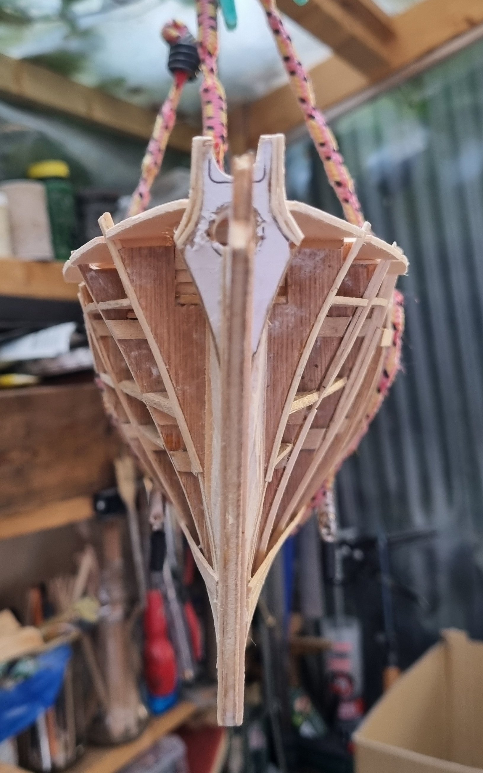
Oops, a nerve has been touched, I will also take the opportunity to say that no offence was taken nor intended in my reply, and if it was taken, then I apologise unreservedly. I will say that my planking will definitely not be mirror perfect, nor would I expect that a commercial construction such as these clippers would have been. But I stand by my point that they would have been run with almost fanatical precision as so much was at stake. So, the fun part. The life boat mkii was a bust, it would have turned out as a boat, just the wrong shape for a lifeboat. I will review my mantua CS plans as this is the same scale and their lifeboats would have been stock. Got back to the main event. I found some Balsa and managed to fill in under the stern, I need more but am not paying £5 for 1/4" * 4" * 24" length, bah humbug. That's half of what I paid for 1sq meter ply I used for the base. Keel has been planked over and garboard strake is done on both sides. I might be making my life difficult using 5" lengths, but there were very few trees that produced 215' planks so it's my little bit of realism. Simon

-
I think a lot of people think the world has gone health and safety mad but in some ways we have gone backwards. I think life on board ship would have switched from abject boredom to manic action in a heartbeat and an untidy ship would have been a nightmare, not just for the risk factors, but for controlling the ship as well. The idea of have to change tack in a force 8 gale at night and having to stumble about in the dark trying to identify what ropes you needed or if they were left tangled by the last person to use it would likely result in the loss of the ship. Discipline aboard ship, not just in the Andrew, but on commercial vessels as well was of the utmost importance. There was one voyage on Cutty Sark well documented where a Bosun used excessive force to discipline a sailor and killed him. The captain, an alcoholic, let the Bosun escape before they made port and to avoid a trial for himself, was suspected of going overboard to avoid the shame for his own misconduct and the loss of his masters ticket. So do we go overboard on detail, probably not, most models are of a ship in port, so would be spick and span in preparation for the next voyage. We do however get the opportunity to decide to what level of detail we go to. Personally, I will go as far as I am able, recognising my own limitations on capability and affordability and will be proad of my achievement. It might not be even close to the model used as your example or models by many here such a Rob, Keith or Chuck but it will be my choice and by my hand and hopefully recognisable as a representative of the ship it's modelled on. Not a rant, just my 2 penny's worth. Simon
-
That is not a bit of guidance, that is a master class in microplanking, producing a museum quality exhibit. Just wow, I haven't tried the rubber bands idea yet, I have a few around, so will have a go. Simon
-
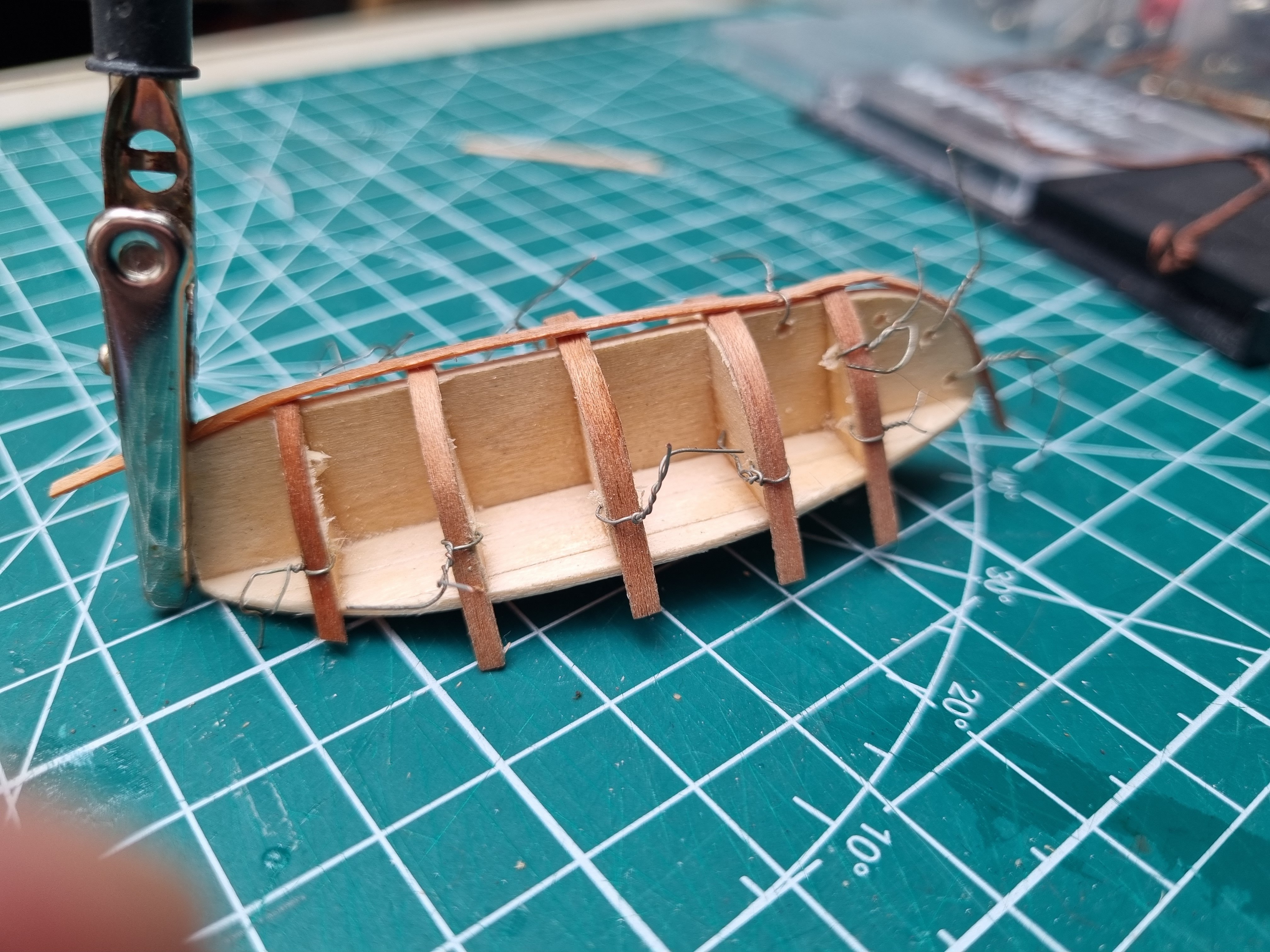
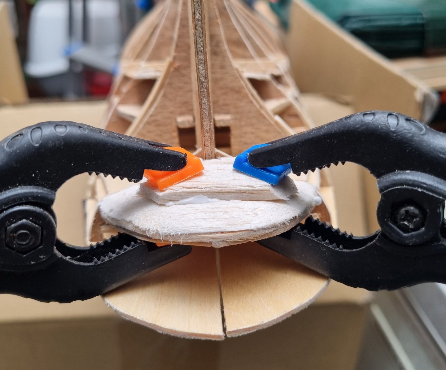
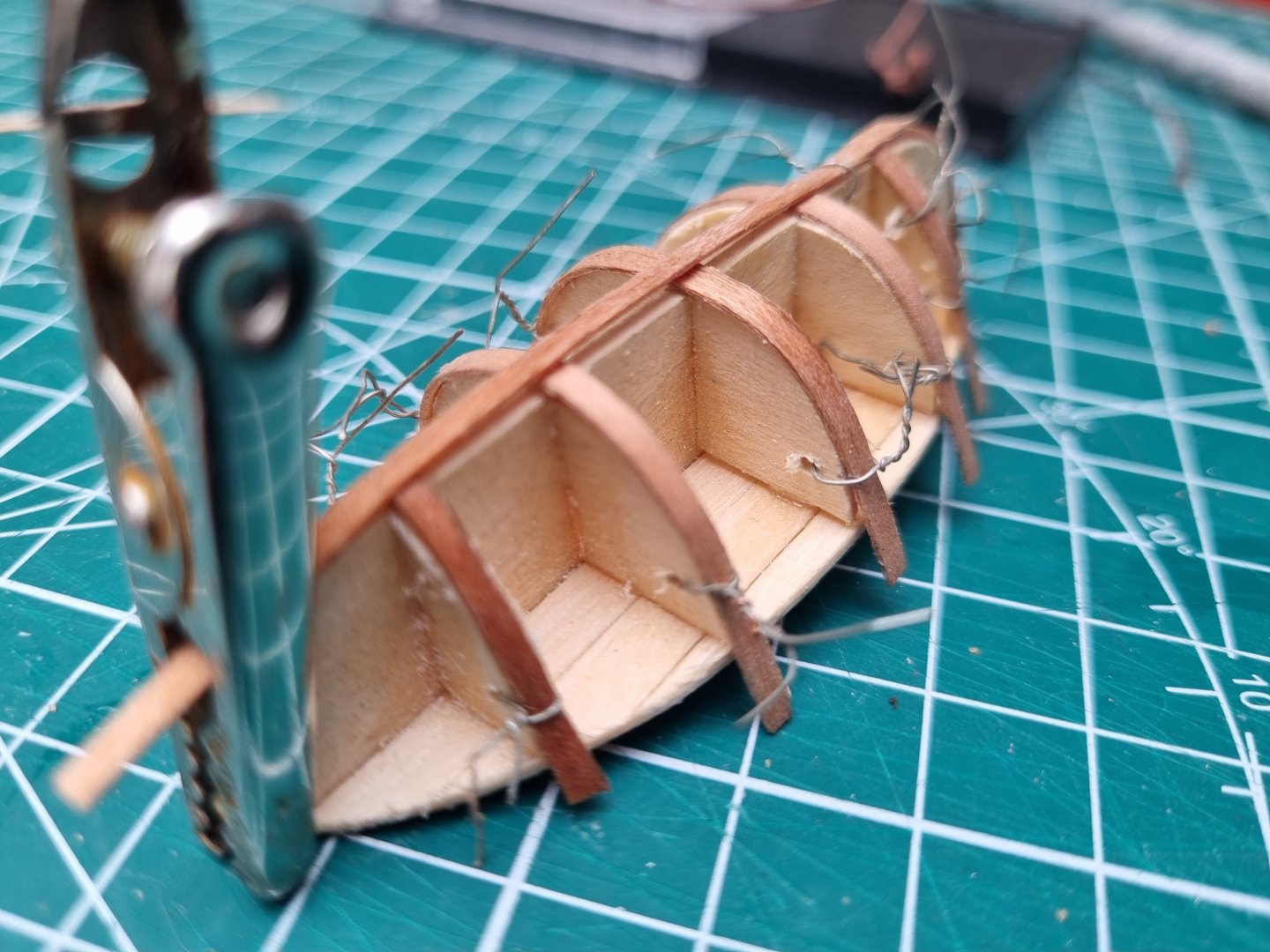
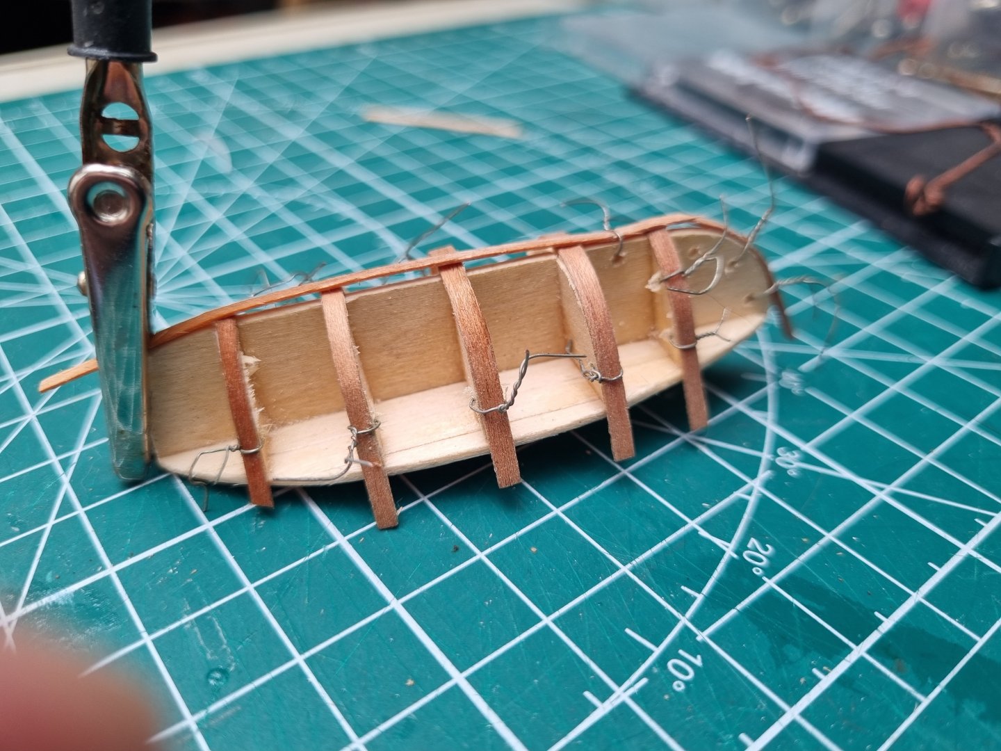
Made a start on the frames this morning. Still experimenting with ways to secure them to the former. Old fuse wire fed through a hole in the frame and twisted to keep the piece in place. These had come from a hot bath so they were soft and eand easy to bend into shape. Nothing is glued yet. Simon
-
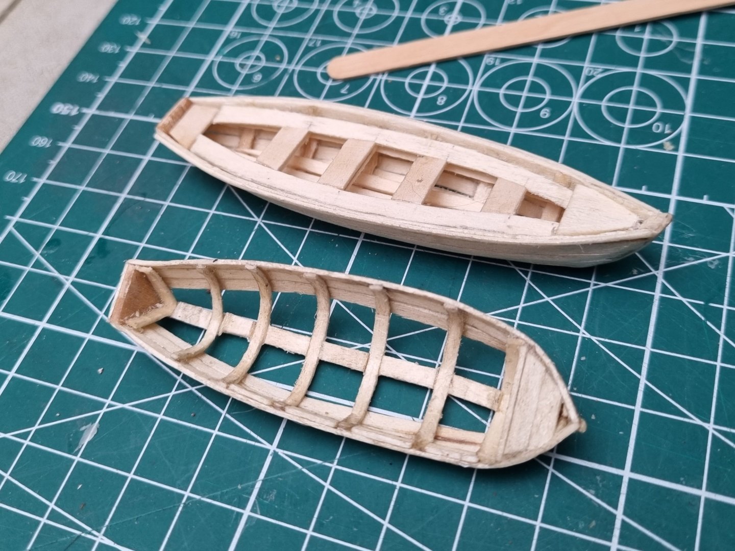
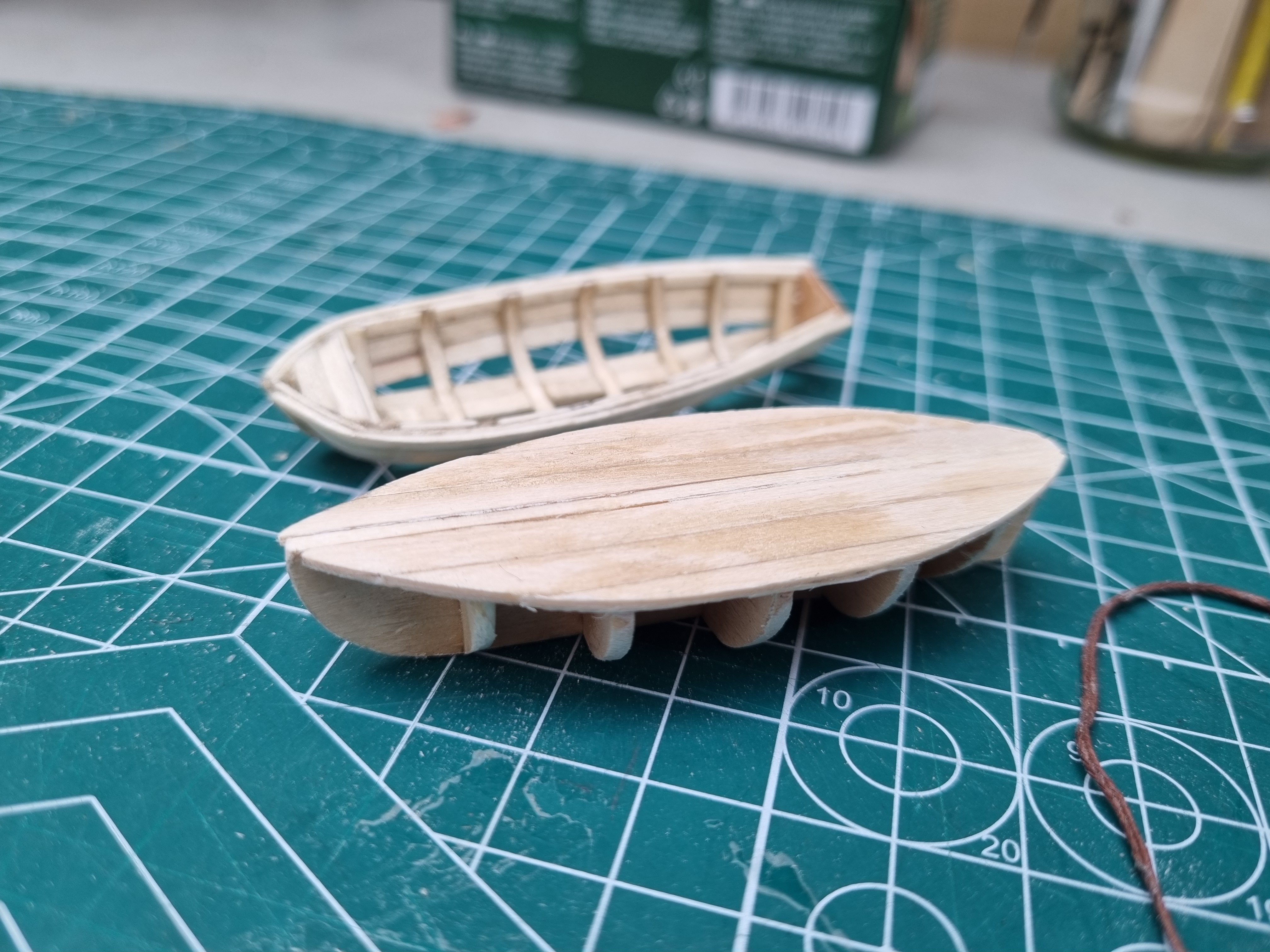
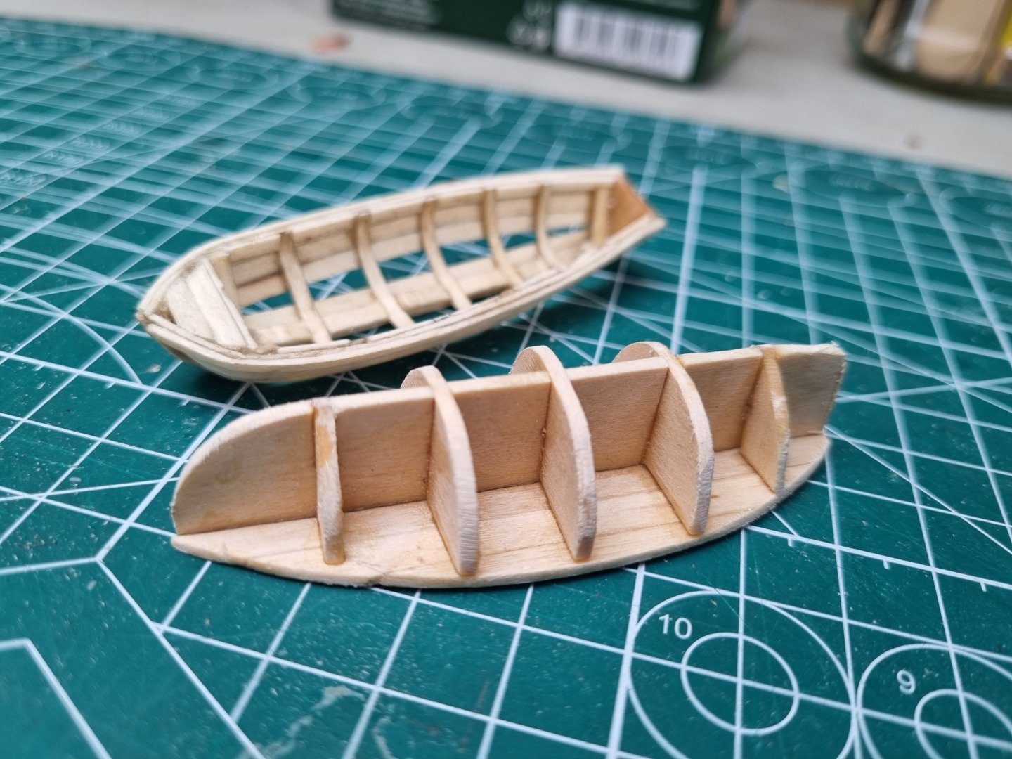
I have not done anymore to the lifeboat, home life got in the way for the last few days. The more I look at it, the less I like it, and the former I used to make it broke when I dropped it. I didn't like the shape at the front and it is not supposed to have a transom. So I have started again and just finished cutting out, assembling and fine tuning the new former. I have sourced some cherry veneer and I will try this as the material for the boats from this. Simon

-
I did one of the garboard strakes and both of the gunwhales before I finished for the evening. I am not working tomorrow so should finish it then. Simon
-
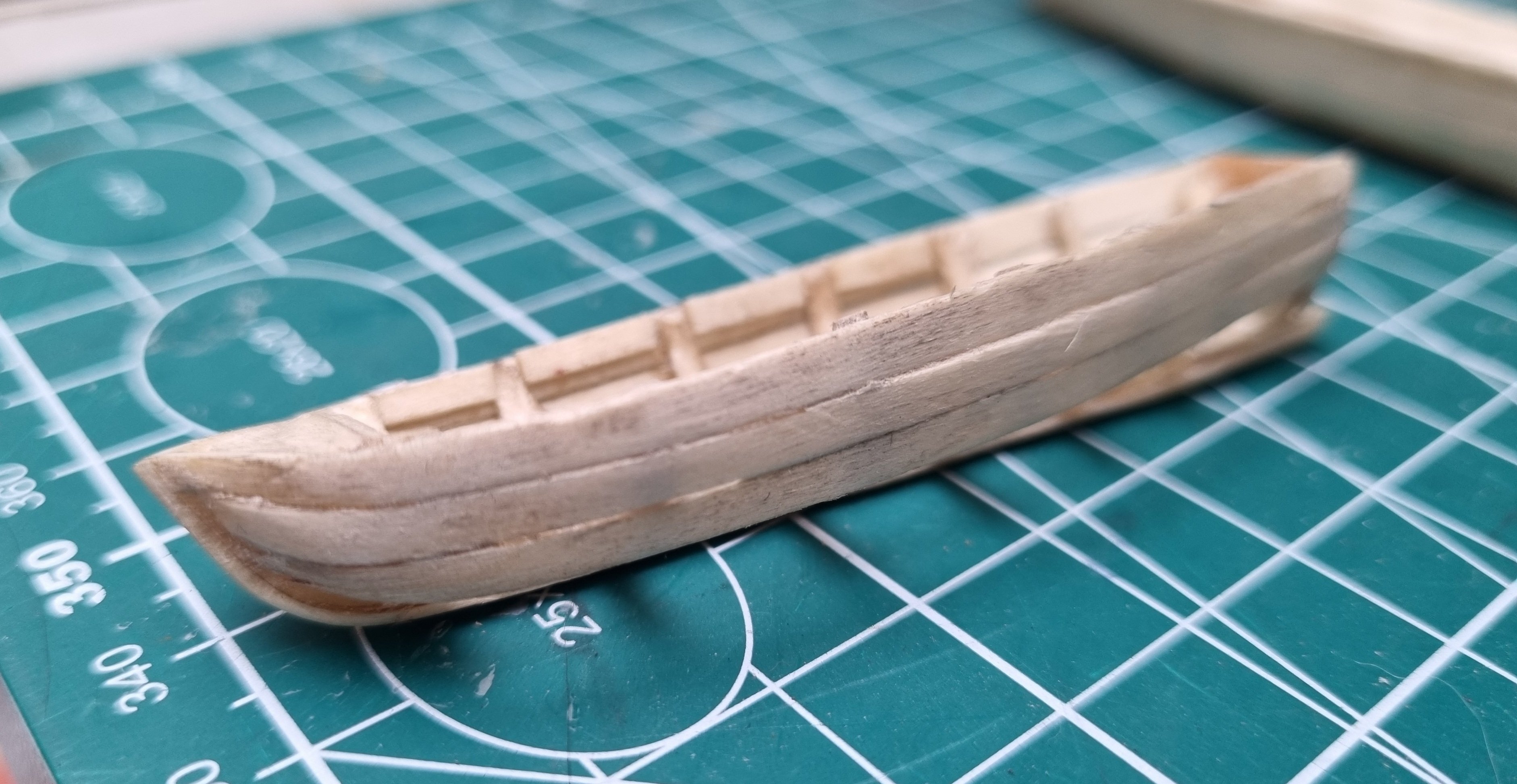
Not sure about this boat. I used lines for a generic 19th century ships lifeboat but the shape just seems off somehow. The front curves are from 15mm copper pipe. I have cut off a couple of rings. Holding a ring in a spring clip, I heat up the ring with a mini torch and the gently wrap the piece to be shaped around the pipe. It seems to have worked and the stakes did not need to have been clamped to create the shape. I will finish it then look for a different set of line drawings if I am still in two minds about it. Simon