HOLIDAY DONATION DRIVE - SUPPORT MSW - DO YOUR PART TO KEEP THIS GREAT FORUM GOING! (Only 24 donations so far out of 49,000 members - C'mon guys!)
×

My Fathers Son
-
Posts
259 -
Joined
-
Last visited
Content Type
Profiles
Forums
Gallery
Events
Everything posted by My Fathers Son
-
If anyone has wondered why there have not been any recent updates from me its because I have had to put CS to one side for a bit. We brought two kittens into the house a month ago and they get into everything. I cant do anything without them sticking their noses in it and they would create havoc with CS so she is up high on the shelf and is going to have to stay there for a little while. In the mean time I will still be popping in to keep up with every one elses progress. Simon
-
Keith, as you know, my knowledge of rigging is what I have gained in restoring my Cutty so I will not attempt to comment on the accuracy, but you have captured the essence of how she should look brilliantly. Keep up the good work. Simon
-
Cutty Sark by NenadM
My Fathers Son replied to NenadM's topic in - Build logs for subjects built 1851 - 1900
I hope so Rob, it is a good start. I would not remake the mast based on this as this part will be below deck any way. I would temporarily set the mast in place and mark the height for the deck level, mast foot, this ring and the spider ring. The ring NenadM has made is a good template for the Spider ring so this can be drilled out for the pin mounts. The mast can then be reassembled and nobody will be any the wiser of the initial slip up. Simon- 4,152 replies
-
- 2
-

-
- cutty sark
- tehnodidakta
- (and 1 more)
-
Cutty Sark by NenadM
My Fathers Son replied to NenadM's topic in - Build logs for subjects built 1851 - 1900
Hi NenadM, Just a thought, but won't you need to insert the base of the mast into the deck? That is a nice neat ring, you will need to install the spider ring above this first though with the loops horizontal to accept the belaying pins. Simon- 4,152 replies
-
- 1
-
-
- cutty sark
- tehnodidakta
- (and 1 more)
-
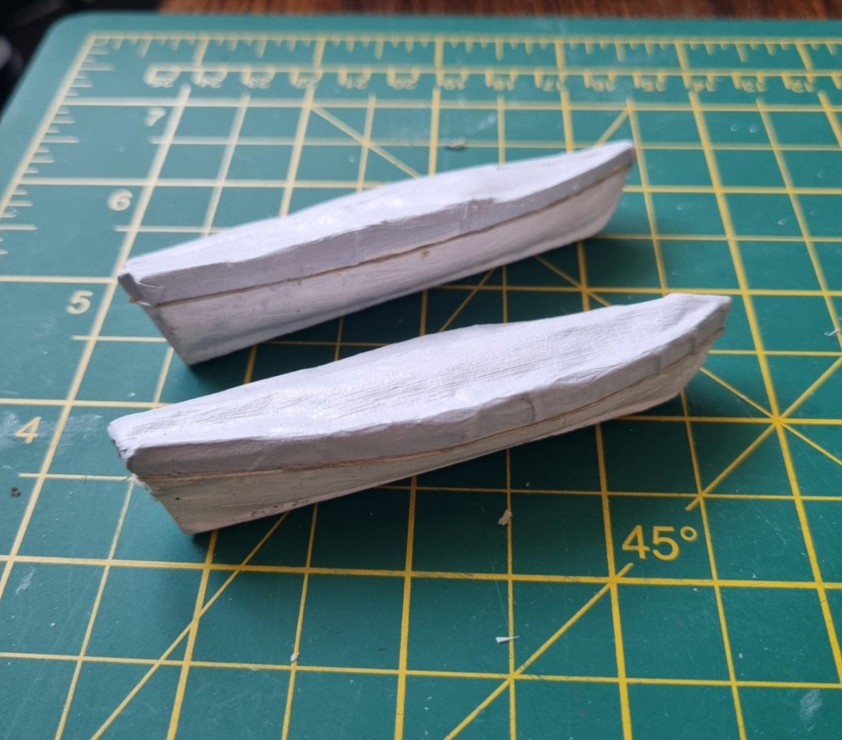
A little more done. I have trimmed up the sides a little a given them a coat of paint. This was normal white with just a touch of matt black. As you can see, I have put a single rope around the edge of the canvas, the zigzag is going to be very small and require a degree of patience. Once this is done, I think I will be happy with these. I will not be doing this for the captains gigg. As pointed out by my Admiral, why go to all the effort of all the detail just to permanently cover it up. The gigg will have a full sett of oars, mast etc on board and on display. Simon
-
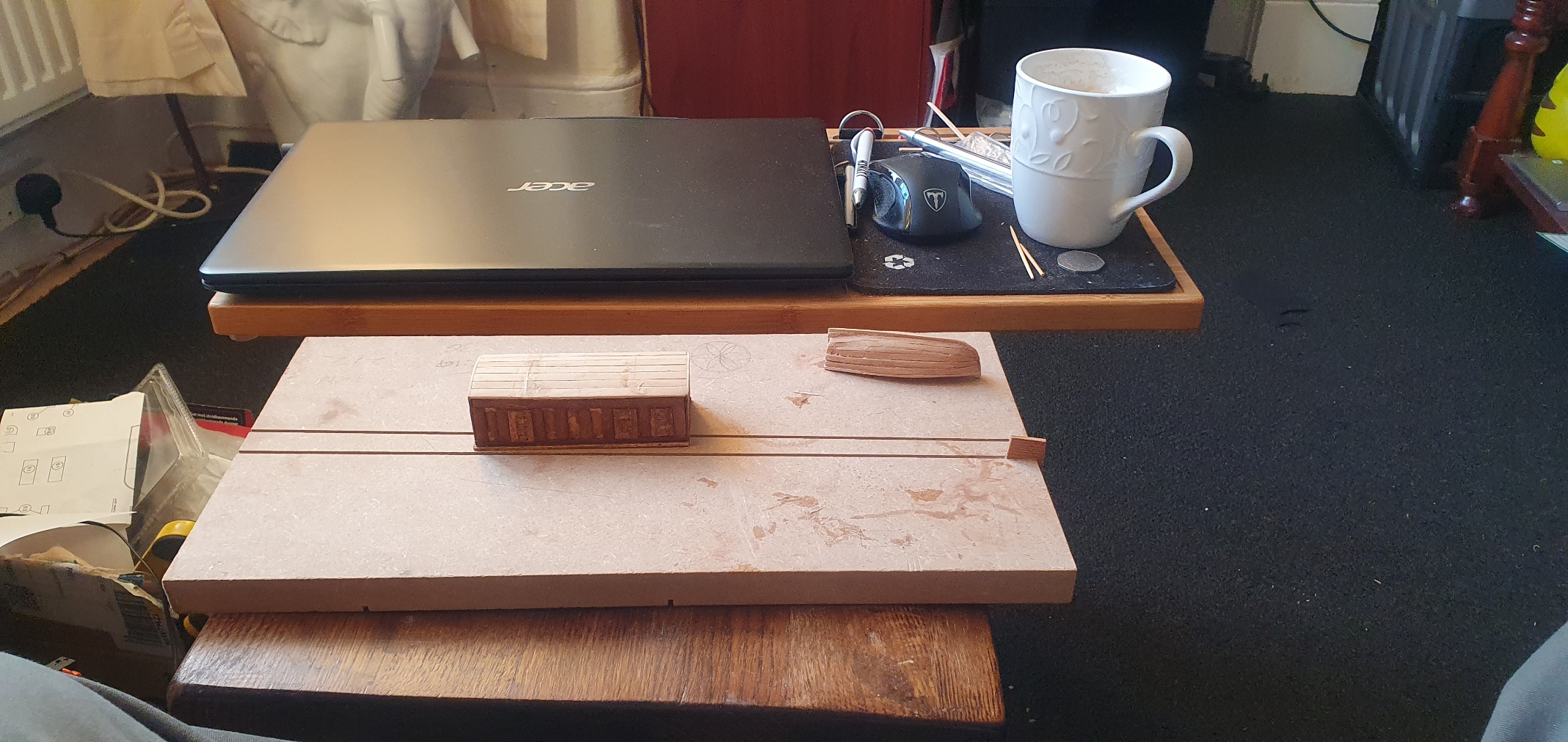
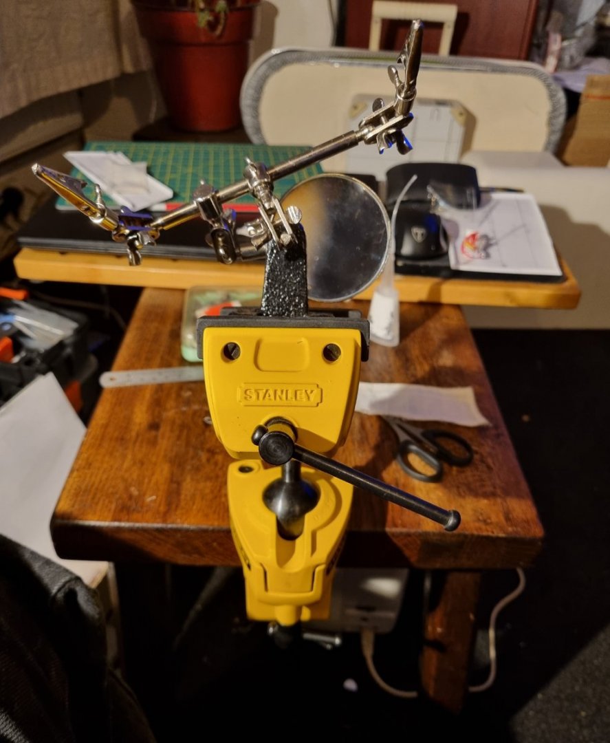
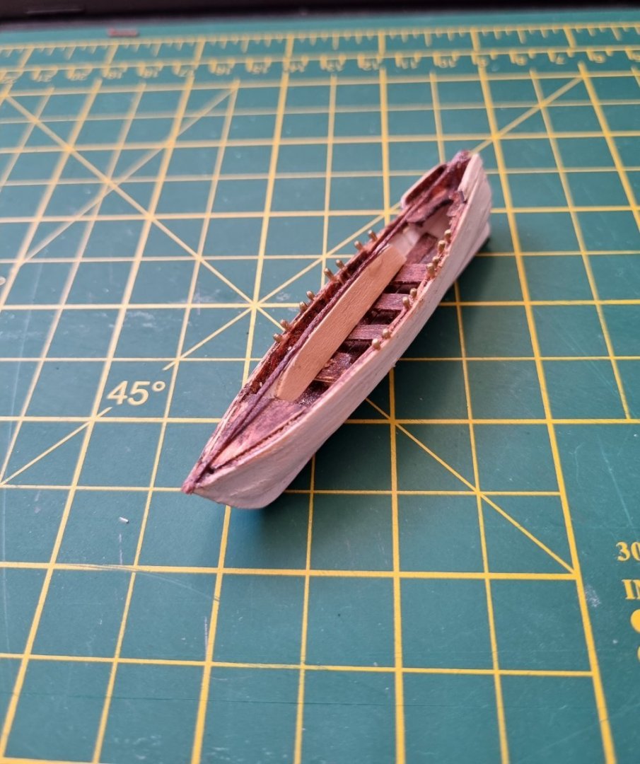
I have not been spending much time on CS recently so there is not much to report at the moment. Still only on the Mizzen, after completing the lifts, I set out to complete a set of sails, no problem sewing these but adding the the loops for the Clew, Bunt and Downloads. I tried brass rings on the Royal and top gallant and while I liked these, I thought I should try to do these in rope and tried several methods on the tops and crossjack. The scale is wrong on these, but rhe material is correct. I need to find a process that will do both. I have an idea but have yet to try it. This is my set up for working on the sails. the multi grips in the vice attached to the table brings the whole thing up to a convenient height in front of me so I can work on the small stuff without having to sit awkwardly. I have mounted the Royal and the crossjack. Here is the Royal. i was distracted by Robs wonderful images of Glory and have started recovering one of my boats. I removed to cloth I had made and tried to find a stiff metal rod to use for the brace across the top, the only thing I had was a shirt hanger. Unfortunately, I could not make that work. I could have used brass but instead I went for something a little more subtle, I length of cord I use for stays. I CA'd this to the stem and the stretched this over the stern post as tight as I dared, after giving the glue a short time to set up. I could see this was not going to give me that arch that Rob has but a length of coffee stirrer stretched for and aft sanded to shape and slipped under the cable gives a nice shape to the rope. i then coved it in masking tape, creasing the edges with my fingernails gently to gi e it shape. My method hasn't given that crisp centre ridge but then i haven't painted yet so this might change at that point. Fingers crossed but looking good so far. Simon

-
Cutty Sark by NenadM
My Fathers Son replied to NenadM's topic in - Build logs for subjects built 1851 - 1900
I must applaud your tenacity NenadM, metal is a much harder (as in difficult) material to work with, and you have produced an excellent end result. Simon- 4,152 replies
-
- 1
-
-
- cutty sark
- tehnodidakta
- (and 1 more)
-
Rob, Thanks for the explanation on the boat covers, I will have a practice on one of my rejects first and if I can make it work for me, then I can bring my Cutty boats up to spec. Simon
-
Rob, She has wonderful clean lines and it is so obvious without her masts at this stage. I have been admiring your boat covers, (I have been admiring everything) but specifically, I have been looking at the boat covers as mine are rubbish in comparison. Are these silkspan? Simon
- 3,560 replies
-
- 1
-
-
- clipper
- hull model
- (and 2 more)
-
I am not too far behind you, I have just made my sails for the Mizzen and will be mounting them shortly. I stopped rigging at the lifts, then worked on the sails, planning on installing from top to bottom. Just makes a bit more sense to me. Loving your work so far. Simon
- 525 replies
-
- 1
-
-
- cutty sark
- mantua
- (and 2 more)
-
I see the advantage of the B&D vice over a normal vice, the extra width gives the opportunity to spread the lines at deck level so you can plan their securing points better. Much tidier. Simon
- 3,560 replies
-
- 1
-
-
- clipper
- hull model
- (and 2 more)
-
My attempts at ratlines definitely improved when I started using the guide cards, I mocked up a clamp gluing extensions to a small clamp then when it was in just the right place, clamped it on the opposite side to balance the weight. I know you are working at a much smaller scale and looking to get a result closer to Robs than mine, but I am sure that this is the way to go. You've got this. Simon
-
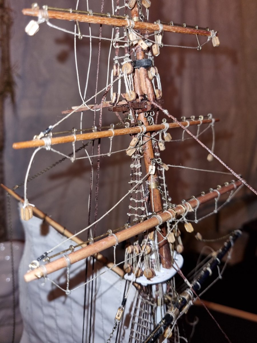
A little progress this evening. Lower three lifts squared away and made a start on the coils of excess rope. Regards Simon
-
I am definitely paying the price of not following this advice and have learned my lesson the hard way. Both yours and Keith's yards are works of art. Simon
-
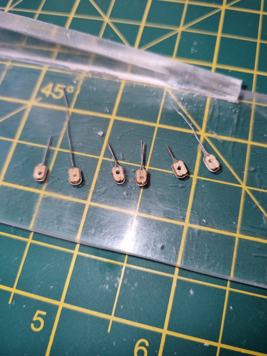
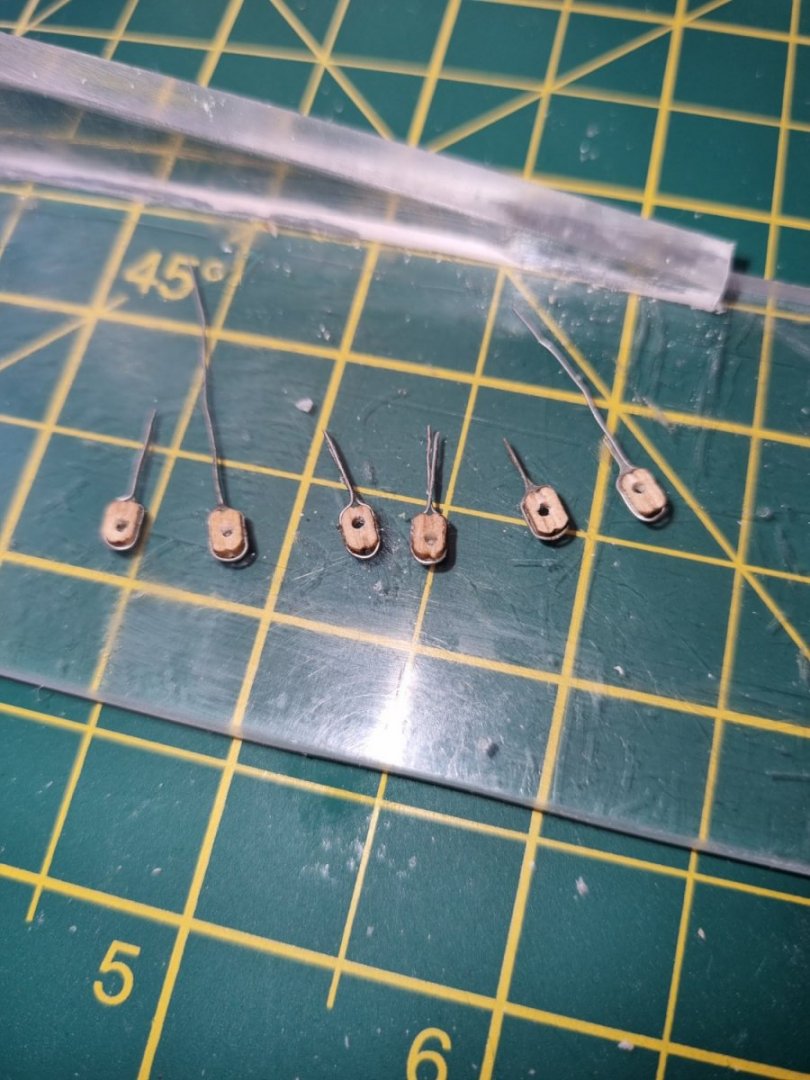
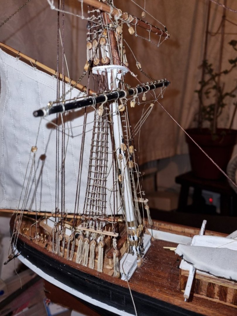
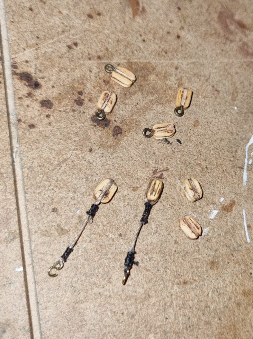
Hi, Made these last night for the crossjack bunt lines. I did try with 2mm blocks to start with but they were too small for my fat fingers to handle. I have drilled through the leading edge of the mizzen mast top and these will be glued in place tonight. Keith, I do get what you mean about working in tight spaces, it seems that ever time I work on one thing, I upset another. 😡 this is in part because I have not actually fixed any line in final position and just tied them of as they would the real thing as I want to be able to make adjustments when it's all in place. Oh well, time to go earn a few pennies again, ta ta for now. Simon
-
Hi all, I am not planning to do any work this evening, other than maybe adjust a few of-the-shelf blocks to suit the purpose of their use, but I thought I would outline how I finally got my head around the thorny problem of when, or not, a block should be used. Firstly, I took on board that what I am working on is "Running Lines" which means these are not Fixed lines like shrouds but are expected to be frequently adjusted by crew members. For each foot above deck the crew member works, the level of risk increases exponenetially so any routine adjustment needs to be at deck level as much as possible. The old joke about "How long is a piece of string" comes to mind but its simple, its the distance between the two ends, and its the two ends that need to be addressed. The best way to simplyfy a system is to ensure that any adjustment is only necessary on one end. So if one end (Point A) is fixed, the the line can pass through as many function blocks (Points F) as necessary to carry out its purpose before going to the other end (Point B ) where it can be temorarily secured, ready to be released and adjusted by a crew member when required. So I came to the conclusion that Points A shoud be Shackles, Points B will be Belaying Pins and Points F will be Blocks of a type appropriate to their function. It might be that the Shackle is attached to the deck, a yard or even to a block when it is part of a block and tackle arrangement, but that is still a Point A shackle as it is permanantly tied off. Points F are for two purposes, either as a multiplier to reduce the load level on a specific line or, to change the direction of a line, or both at the same time and this can only be achieved with Block(s). So that is my rational behind the use of shackles and blocks in my rigging. Simon
-
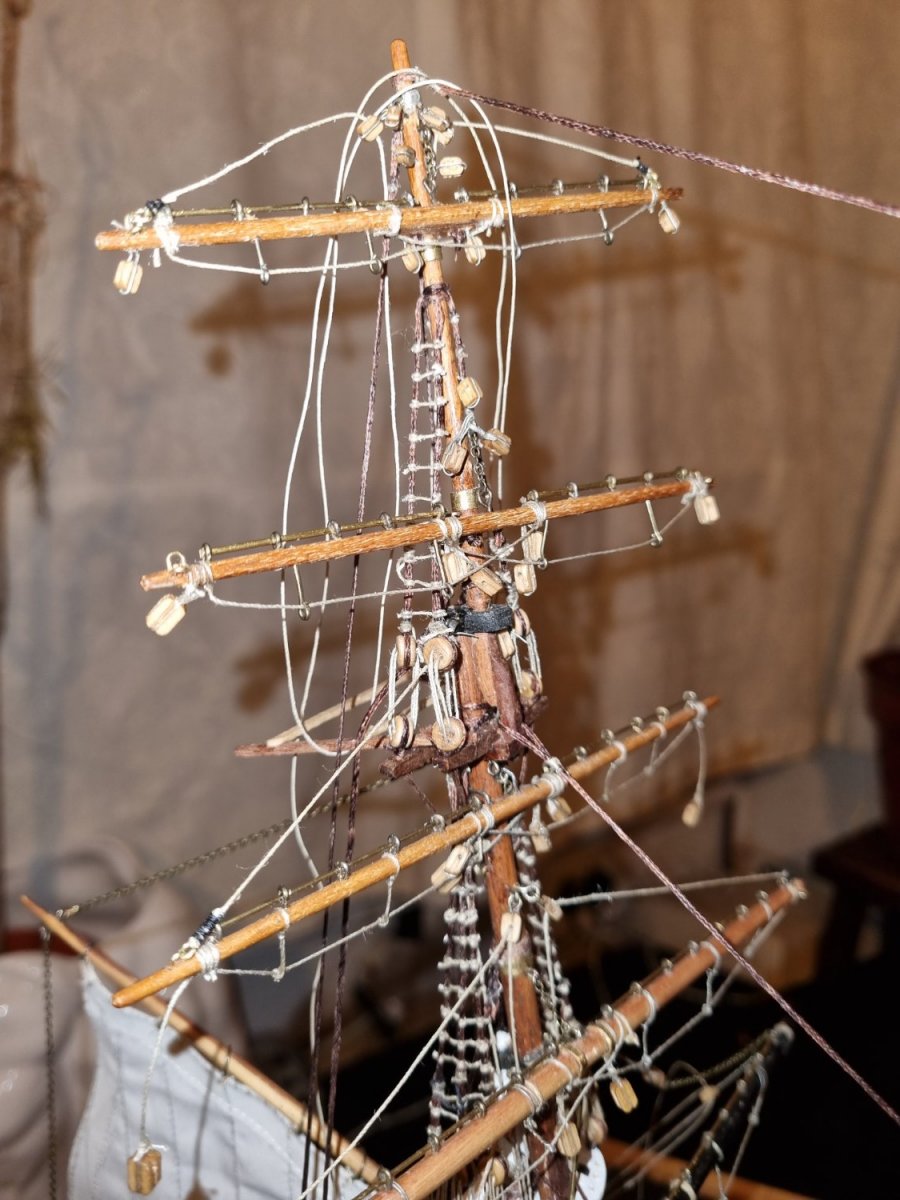
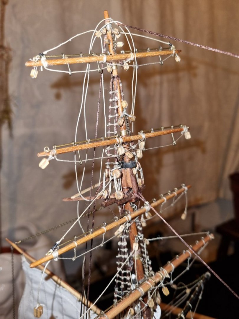
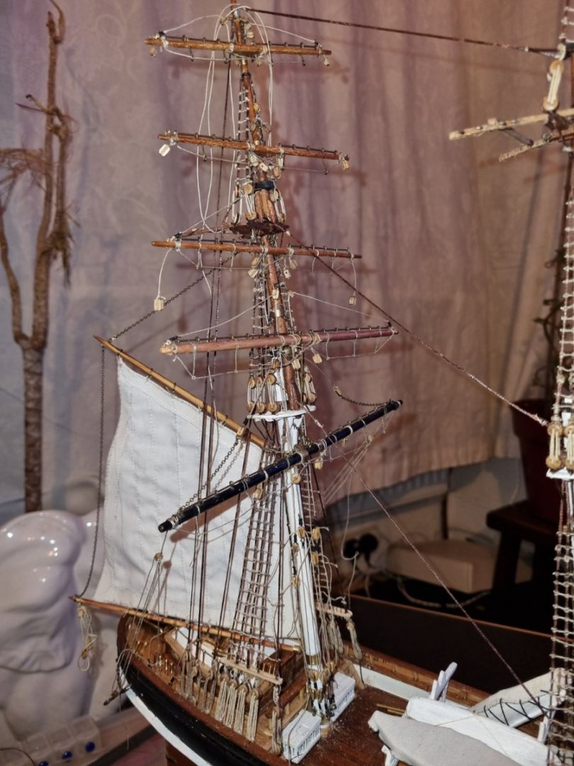
Well, I have been spending quite a bit of time on the lifts on the mizzen mast. Not finished yet but thought I would post a progress report. Simon

-
Didn't want to take the boat down this evening so spent some time preparing some blocks for the tackle for the Mizzen Crossjack and lower top yard lifts. These started out as basic 5mm blocks which I have shaped so they are more oval. The two with tails will be hooked onto loops at the base of the mast. The upper top will have similar arrangement but will have 4mm blocks treated the same. The topgallant and royals are secured near the backstays, they will have similar block and tackle, longer but the blocks will be in 3mm. Takes time to adjust the blocks and stop them looking like a small brick. Simon
-
After having a good read through Keith's suggested reading and downloading a few of the plans that were linked, I now have a much better idea of where I am going. I was right about the excessive use of blocks to connect lifts to the spars/yards and am now working on devising proportionally sized anchor points and shackles to connect the cables. Using a combination of the Revell and Cambell plans, I can see where the lifts are anchored on the deck so know what to do next. One thing I am curious about though is, why is the port side equipment given stronger lift capability than starboard, the drawings show the starboard to be on lighter gear? Can't show images just yet as I can't add tension until the sail is fitted and the downhaul takes up the slack as the yard doesn't have enough weight to do this in itself. Simon
-
I too am confident that you will find your way through this as you have done with your previous hurdles along the way. Simon
-
Keith, You were right about the last link in you post, the draftee has taken Campbells drawings and made sense of it and the annotated it in colour setting out what equipment goes were and in what order. I have house guests from USA till the weekend but will get to reading as soon as I can. Thanks very much for this. Simon
-
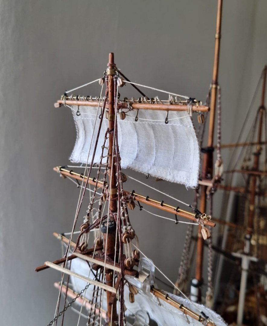
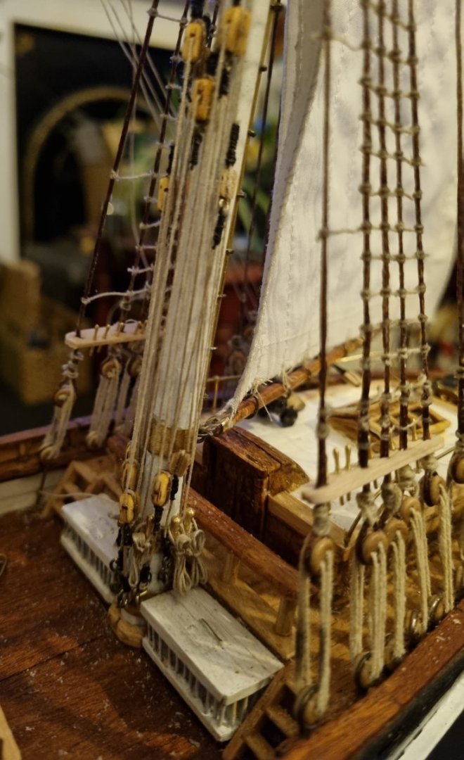
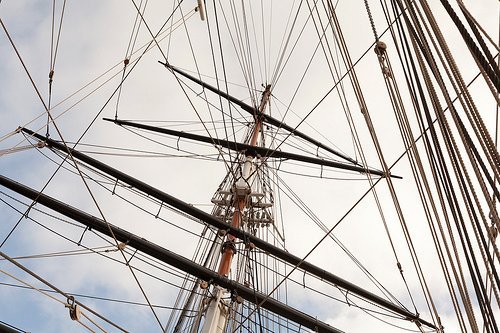
Hi Keith, Well, I have been modelling my most recent attempts based on your excellent example set out in your build, but when Rob posted his most recent images of his yards, I noticed that he had not installed a block on the top of the Yard, just a Hoop for a Shackle to attach to. This made me look at the Cutty Sark herself and while it is difficult to see above the Yards from the deck level, I cant see any blocks at the ends of the yards. I do understand that she is not fully rigged, there are no bunt or clew lines, or leech lines evident here but the Lifts and Braces are installed. In fact, I suspect that these are the only running lines that are installed. I can see the Blocks on the Braces and those for the lifts close to the Mast, but none on top of the yards. You can see on the Coarse, Lower Top and Upper Top, there are Block and Tackle connecting the yards and that definitely will require blocks but I think that I will omite this on the Top Gallant and above. Simon
-
Thanks for the likes and I really appreciate the support, it has helped me a lot on my learning curve to restore this model. I have been looing at Yards and how differnt models get fitted out and one thing in particular is puzzling me. How do you connect the Lifts to the end of the yards. Some people mount blocks and attached the lift that way, but looking at Rob's Glory, he has hung a block below for the Clew Line but only has a Shackle above the yard to connect the line for the lift. There is no need for doubling the line to ease the lift, except maybe the Course and Lower Top Yards, so why would there be a need for a block at that point. Please feel free to comment. Simon
-
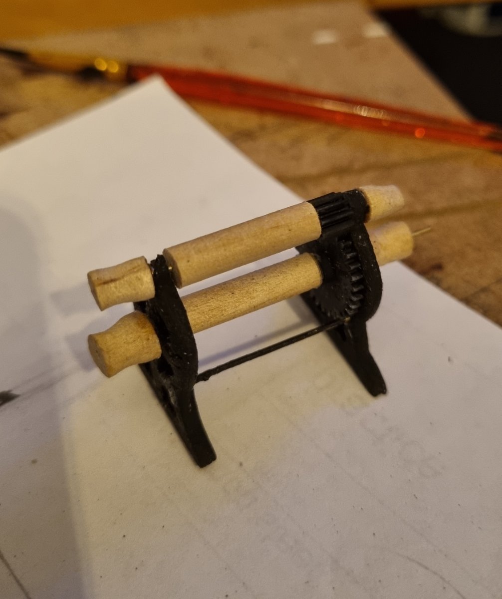
I had toyed with the idea of making a rope walk and had bought a bag of assorted plastic cogs. A couple of them came in handy.
-
Right, that is the Hoover damage remade. I think these things should be a little smaller but I looked for one in Kit form and could only find 2. One was the Mantua 18mm model for Thermopylae but that would be 1:124. The only other one was 50mm which would put it at 1:76 . So my hand made one will have to do. So now it's back to fitting out the Mizzen mast. Simon