John Murray
-
Posts
100 -
Joined
-
Last visited
Content Type
Profiles
Forums
Gallery
Events
Everything posted by John Murray
-
I started to sand the bulkheads on my model of HMS Winchelsea today. It will be a long, slow process doing this. I made a video to show the process to my friends and family. https://youtu.be/JrVObBMVb4c?si=fpDXILDY2NxrL-Ev
-
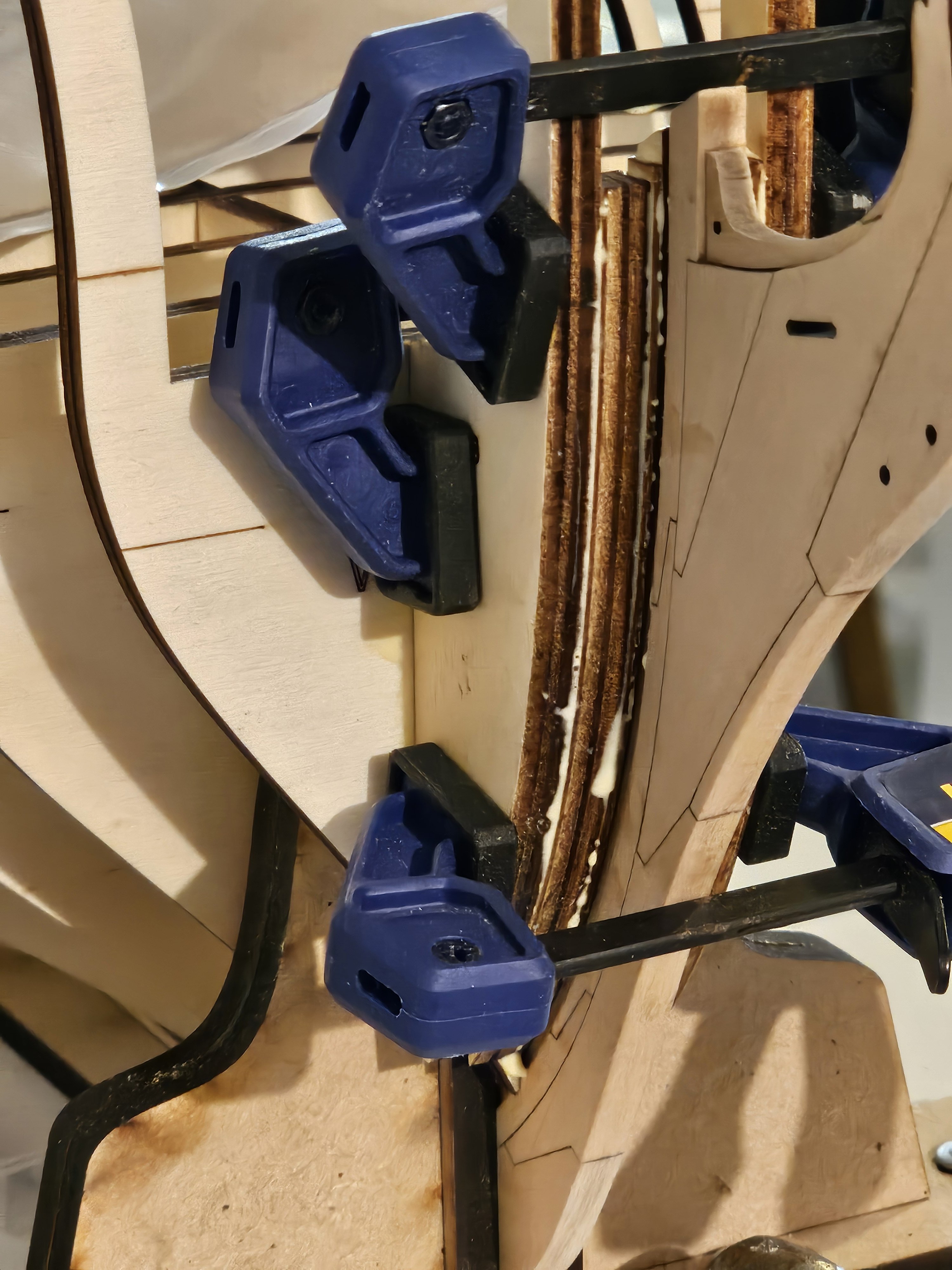
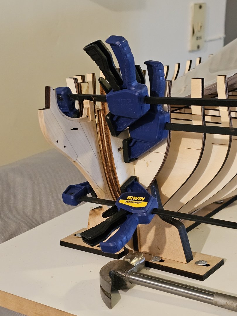
Today I spent some time using corner brackets and foldable clips to protect the bulkhead extensions as suggested in the chapter 1 instructions. Naturally, after placing the last one, I snapped off one of the rear extensions after a slight bump whilst placing it into the building board after making adjustments. Luckily, the broken piece fitted into one place only so was easy to glue into the correct place with Titebond II. It has a bracket to align it vertically and two foldable clips to keep pressure on it whilst the glue cures. This demonstrated to me how much care will be needed fairing the hull.


-
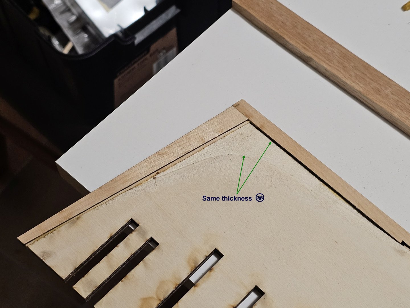
I visited a local specialist timber supplier who had various veneers of different thicknesses. I got 3 pieces of 750mm x 190mm x 0.5mm thick Rock Maple. I cut two of them into 4 pieces just over 300mm long. I then used Titebond II to glue two together giving me 2 final pieces at 300mm x 190mm x 1mm thick. The glue layer will add a touch of thickness I hope. I have them both under a weight of books to keep them flat until fully cured overnight. Checking them this morning I found the veneers had corrugated due to uneven glue thickness when applying it. Bugger. I know why though so that issue won't crop up in future. So, today I went into the makerspace and used the laser to cut 6 of the spacers (I only need 4) from the 0.5mm veneer I had. I glued two of the spacers together which gave me 1.15mm thickness which is close enough. I clamped the two of them between two planks of flat wood for two hrs. Releasing them, I found the laminations were flat, not corrugated. These two final pieces are BF-1. There are two pieces BF-2, and a further two pieces BF-3. 2 stacks comprising in order, BF-1, BF-2, and BF-3 were glued together and placed into the bow of the ship and glued into place. Now they are cured, It is time to start fairing the hull. I anticipate a few days to do this as I am house sitting a dog in their house for the next 10 days. After that, I start assembling the gun ports.


-
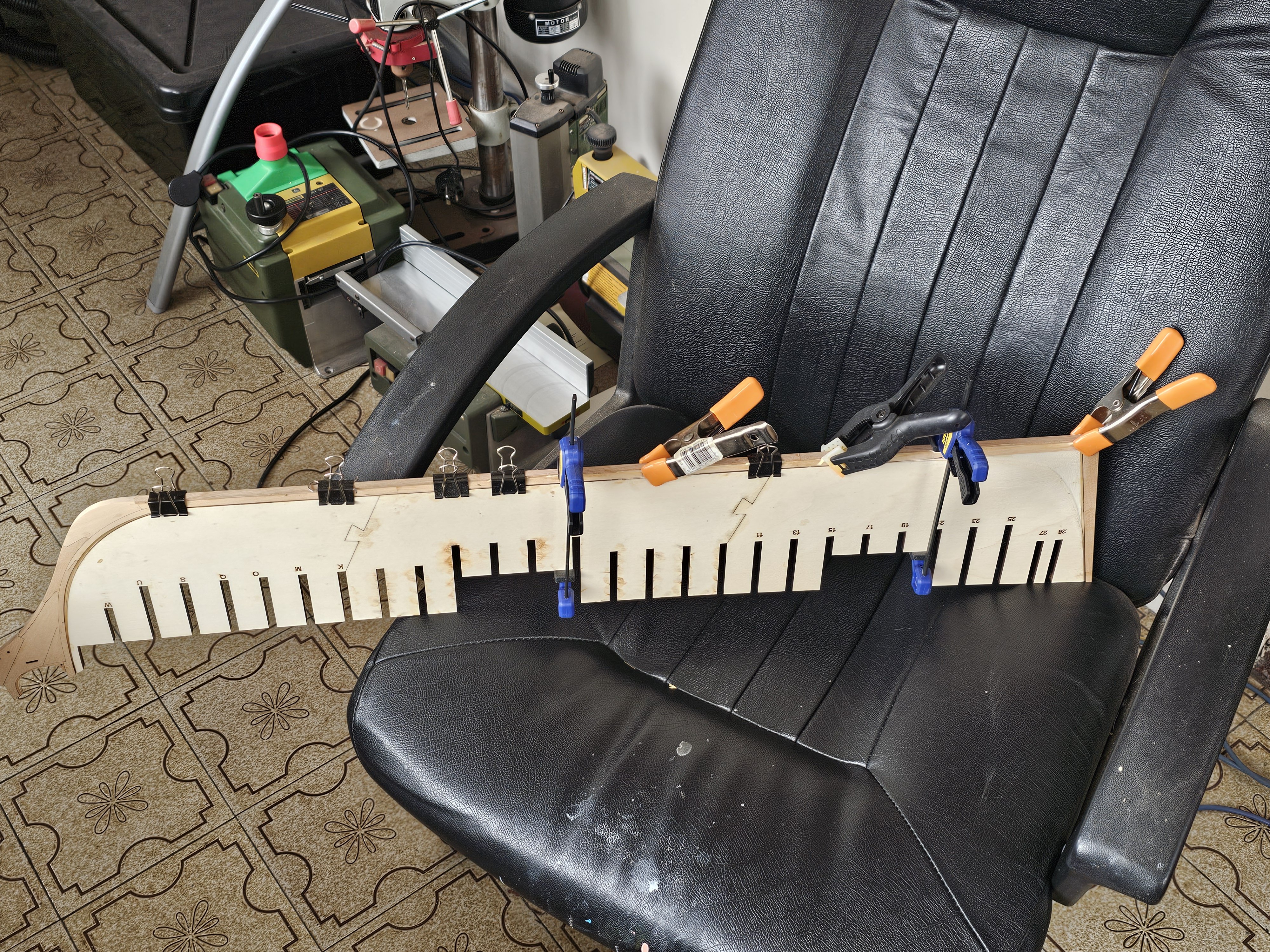
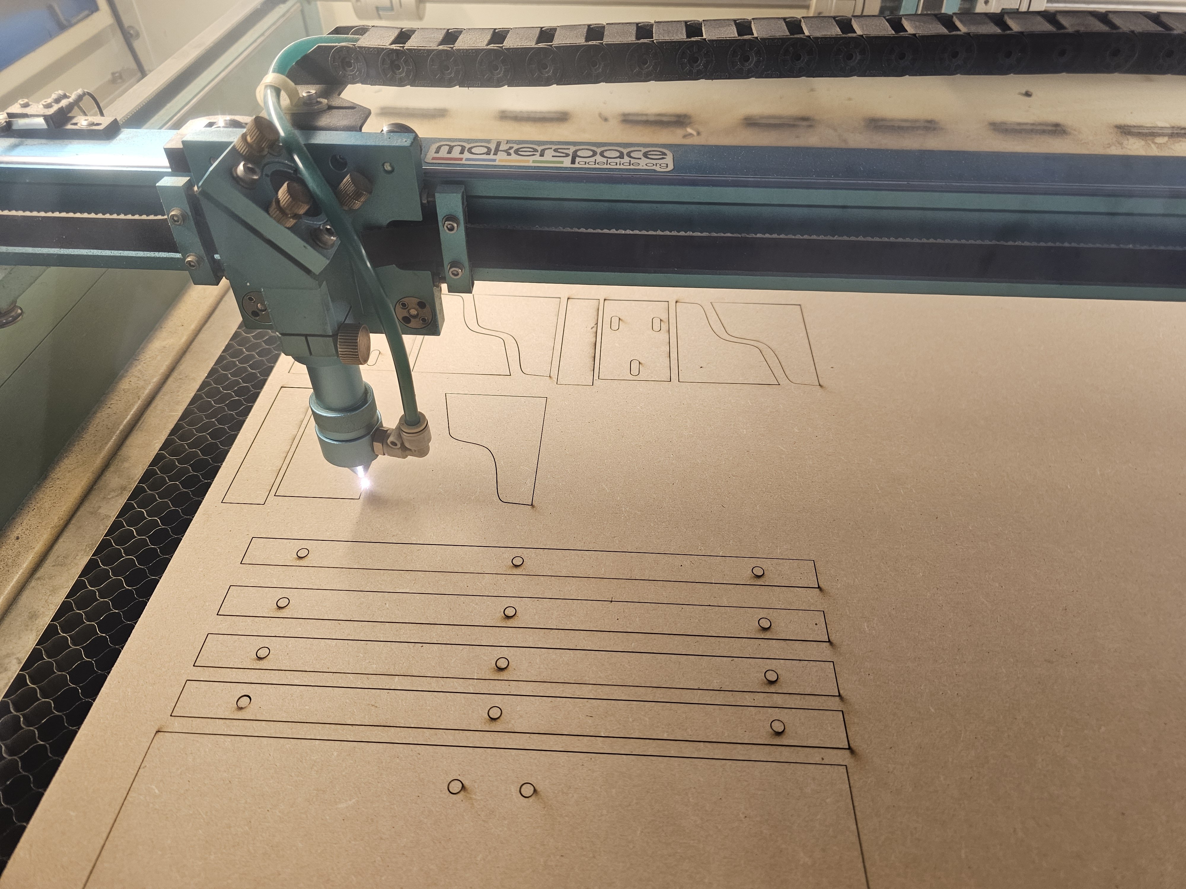
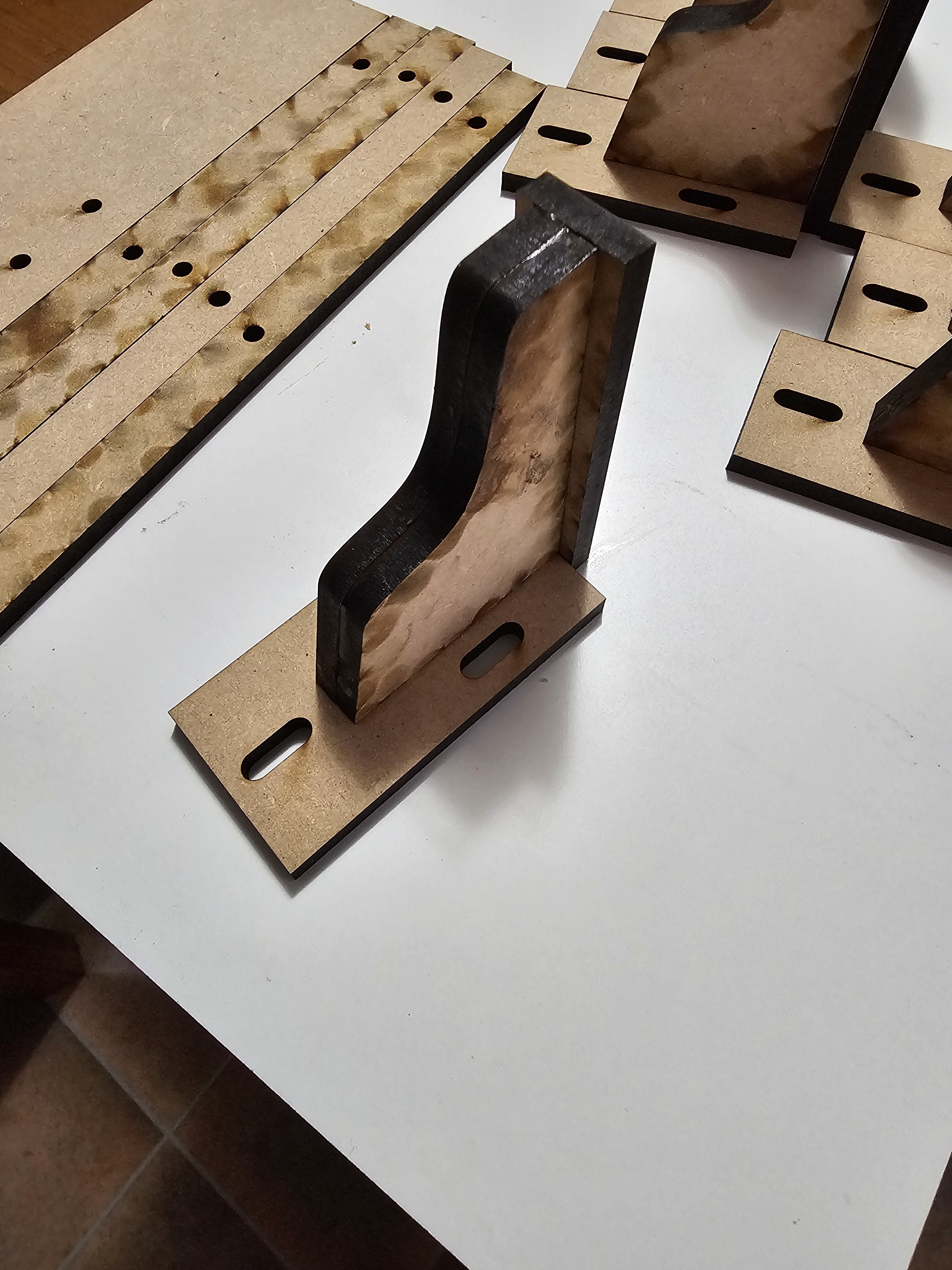
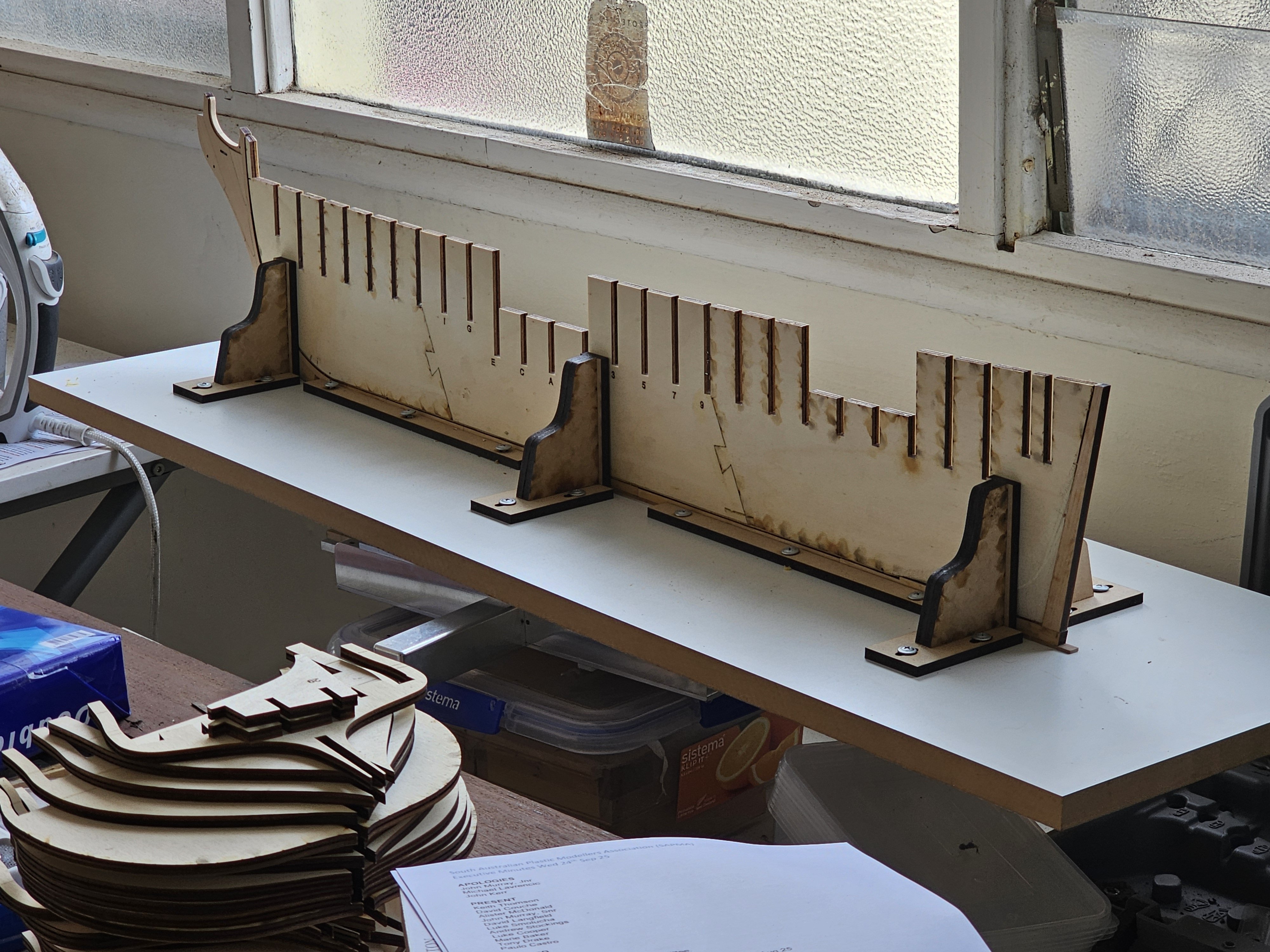
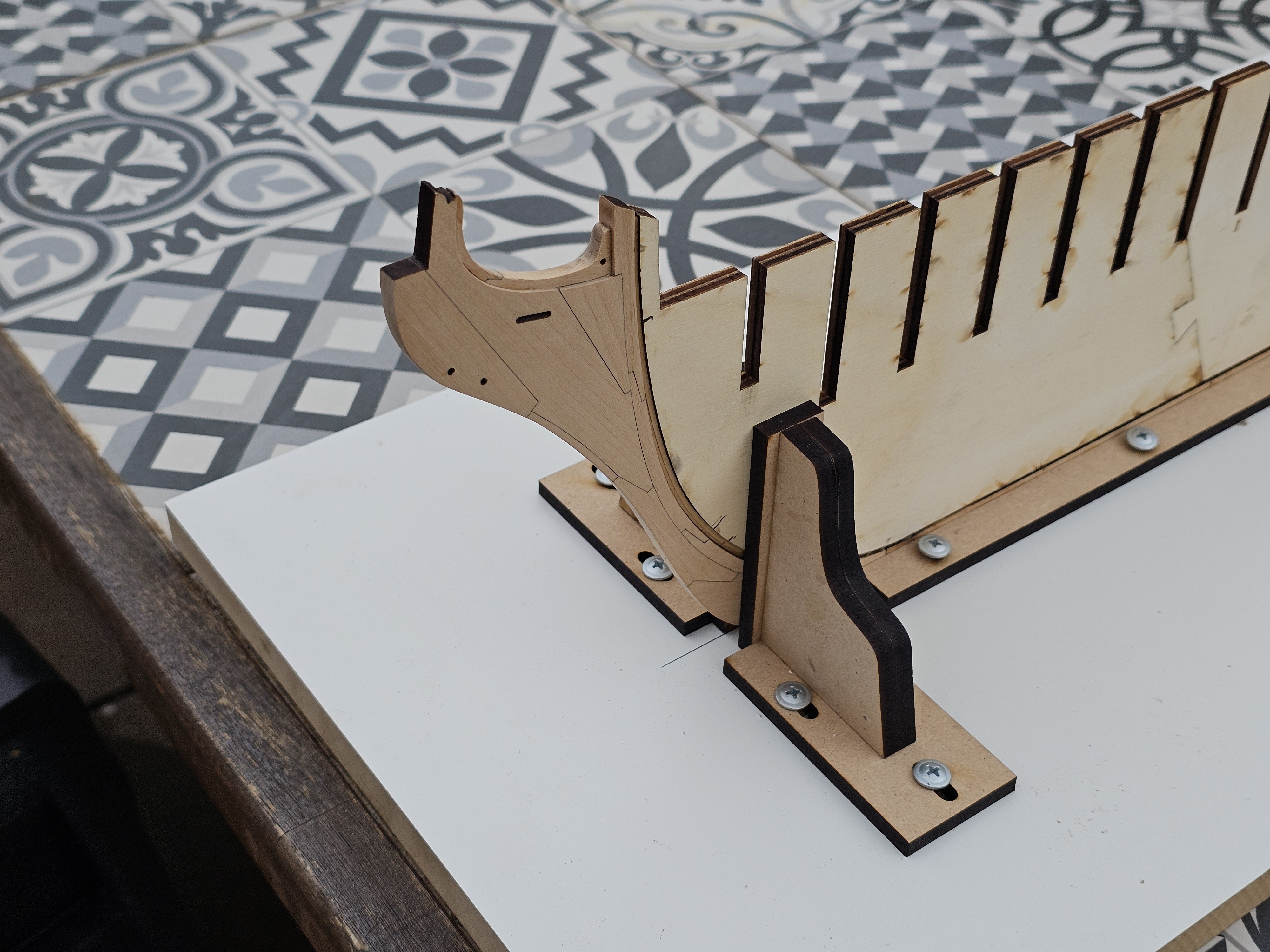
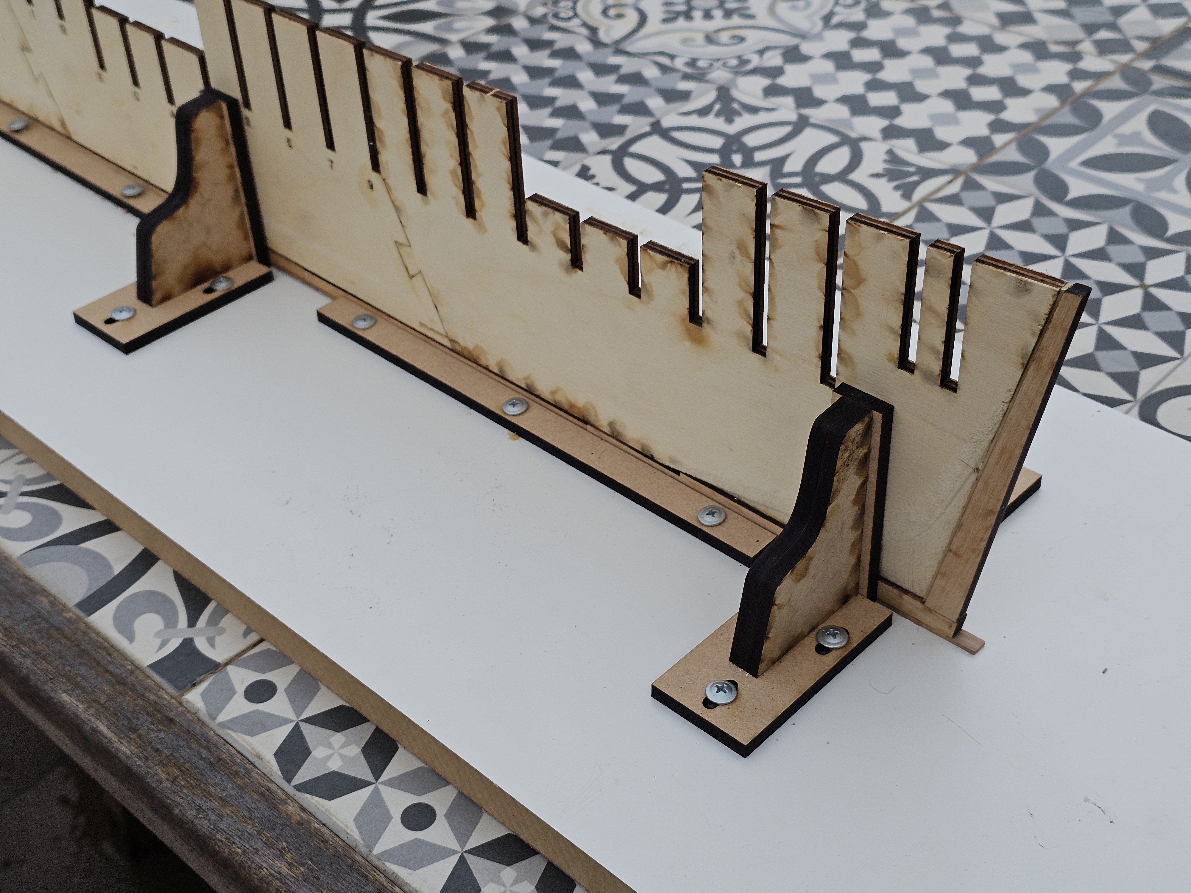
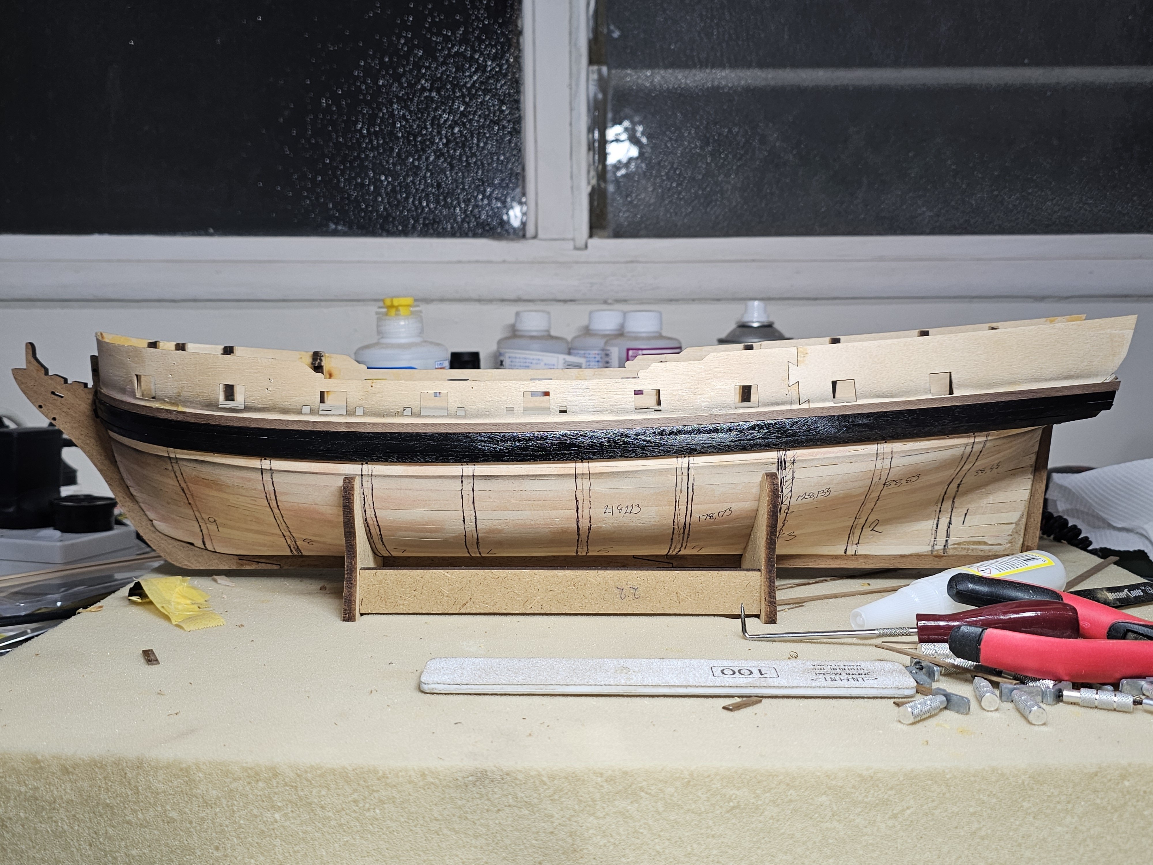
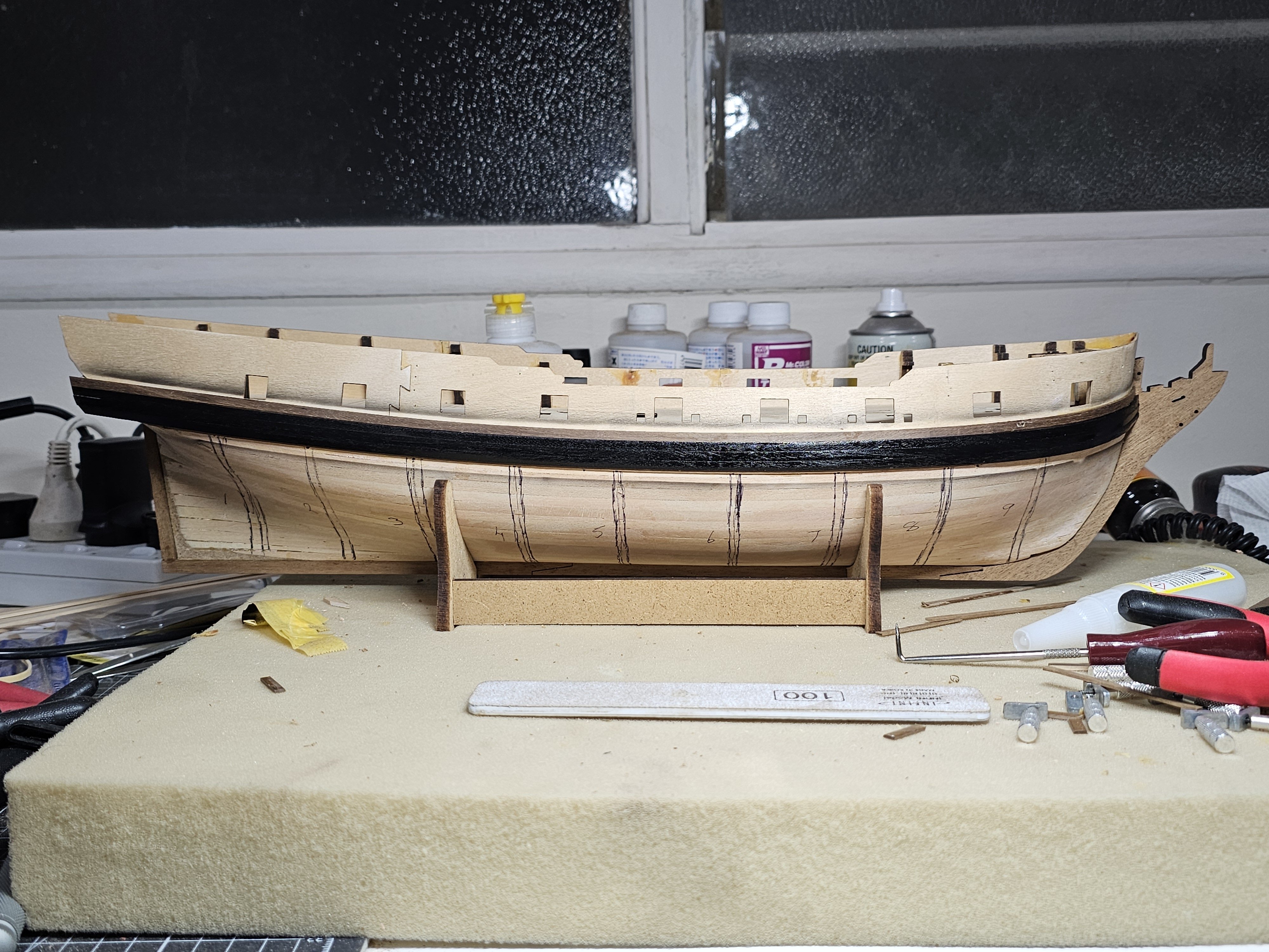
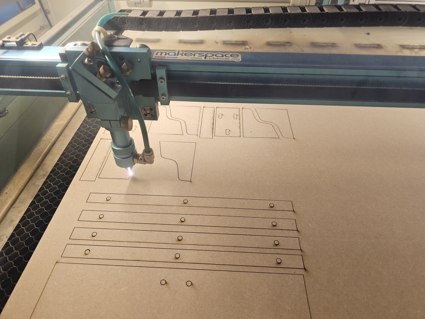
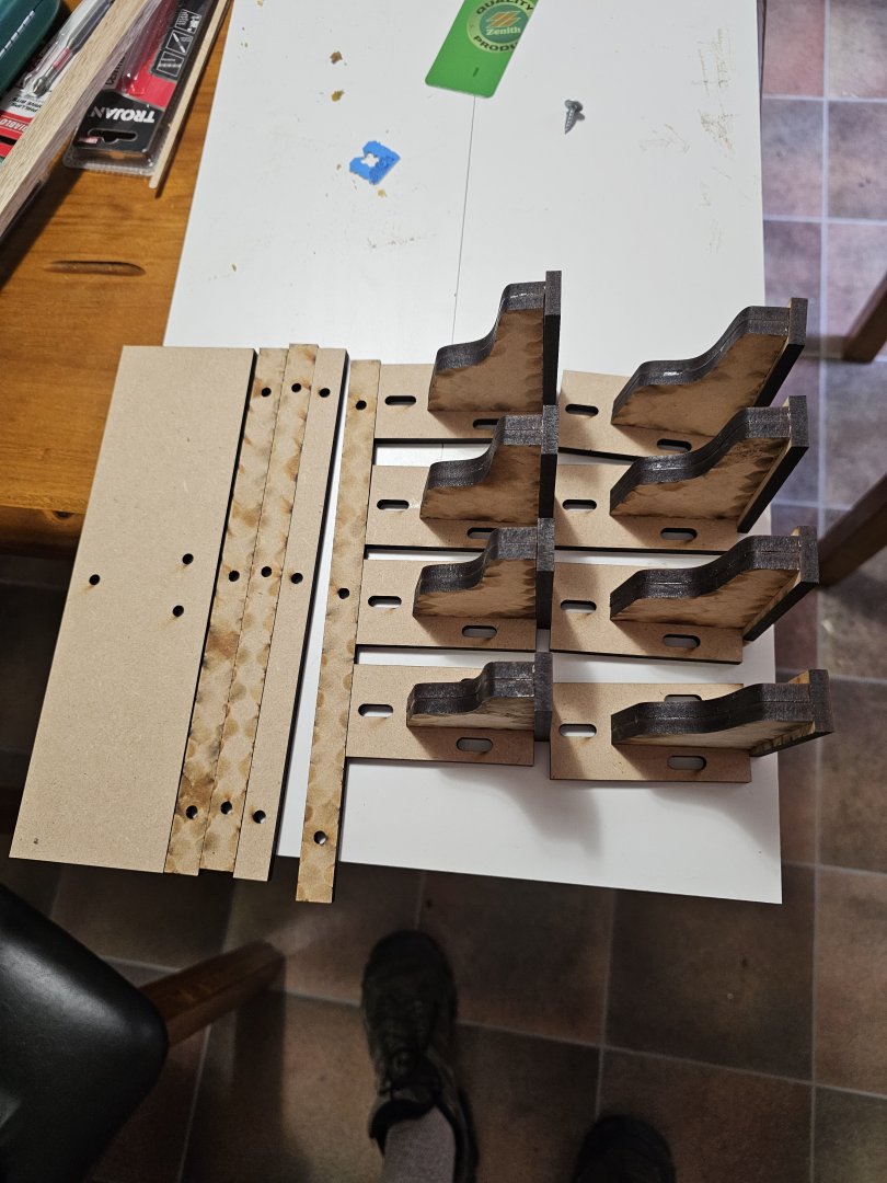
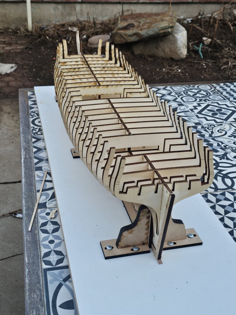
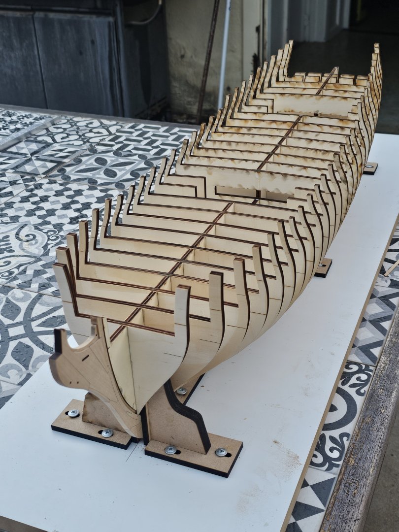
I have been busy with life but have been pottering along on the Winchelsea. Over the last several months I have added the Rabbet, the Keel, and the False Keel. Various small issues were encountered but I tackled them one at a time. After a long layoff, I was eager to get going and screwed up when removing some of the bulkhead former at the stern to allow planks to lay correctly. I did not angle the thinning, i gave no thought and took it down evenly. 😒Some filling will be required. After that, the keel and false keel were added. After cleaning the joins and surface up, attention turned to my building board. In Lightburn, I designed some 6mm MDF supports that needed to be cut by the laser as well as 4 strips of MDF that are straight edges. Yesterday, I used the laser cutter at Adelaide Makerspace to cut a load of sub assemblies from the 6mm MDF. The were assembled into braces that hold the bulkhead former, and the keel straight. A couple of hrs later and I had the building board, supports, and the bulkhead former completed and in place. I then glued in the bulkheads making sure the orientation was correct for the numbered and lettered bulkheads. I then turned my attention to the 3/64th inch pieces for the window spacers, the BF-1 spacer shims and the rear transom. I got 3 veneers, 1 . My Proxxon machines cut to a width of 80mm max. So, how to get a sheet or two of that size (I use mm, so it is 1.2mm sheets needed.) I visited a local specialist timber supplier who had various veneers of different thicknesses. I got 3 pieces of 750mm x 190mm x 0.5mm thick Rock Maple. I cut two of them into 4 pieces just over 300mm long. I then used Titebond II to glue two together giving me 2 final pieces at 300mm x 190mm x 1mm thick. The glue layer will add a touch of thickness I hope. I have them both under a weight of books to keep them flat until fully cured overnight. I will then go into the maker space and use the laser to cut these shapes out. Hopefully my next update won't take as long.


-
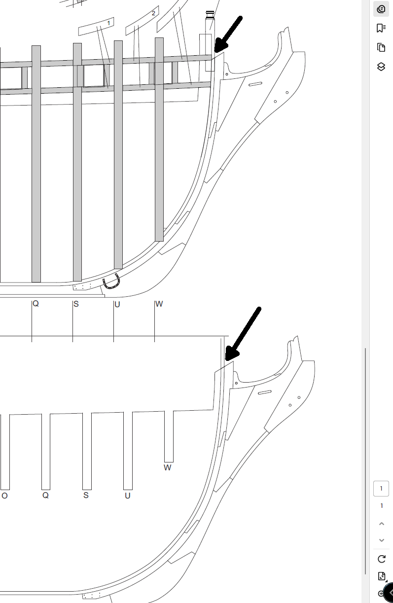
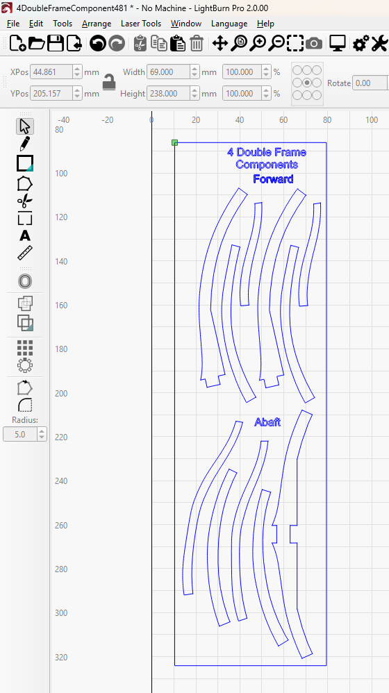
Morning All, I have downloaded all of the files for the Triton build. On my HMS Echo cross section, I used rubber glue to place the paper cutouts on the wood so they could be cut out. I found this not a particularly good solution as the glue would quite often let go.. For this section I have taken the assembly pdfs and imported them into Lightburn to see if I could separate out the frames only and place them onto the Lightburn working area. Shown below are the forward and abaft components for the 4th frame. Since the frames are symmetrical for both sides I only needed to copy the relevant ones for the opposing side. I plan to lightly vector etch the wood. I had considered cutting them on the laser but the charred edges would need cleaning up. Any thoughts pro or con for doing that? I am combing the pdfs and the wood sections. Best I can make out is that all timbers on each frame are the same thickness at 5mm thickness.
-
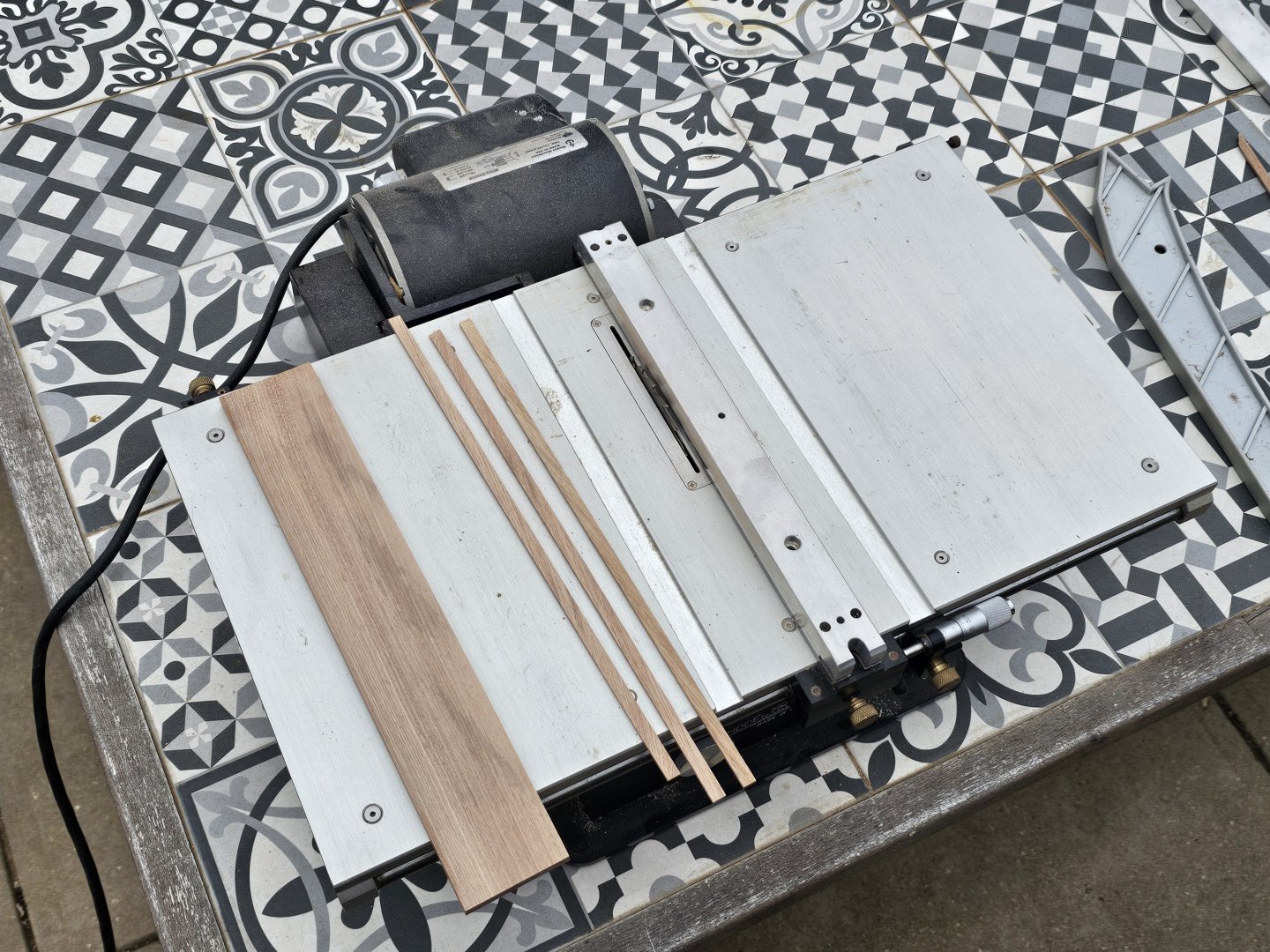
Cheers Frank. I have milled some planks up on my Proxxon planer and thicknesser. It machines, bends, and sands ok.
-
Dusan, Thank you for that. The picture does help. I am glad to see this issue isn't just me. I will add more to the rabbet and then thin and adjust until the stem fits correctly.
-
Yes, that makes sense.
-
Cheers. 🙂I searched the forums but it seemed a 50 50 split between basswood and limewood being the same and they are different...
-
One further question I have is that I have just discovered a local supplier to me able to supply sheets and strips of Limewood, Mahogany, and Walnut in the lengths and thicknesses I will require. This would be a better option for me if the woods are suitable. The Walnut and Mahogany are darker though and my preference would be a lighter coloured wood such as the Limewood. Searching the wood forum here did not assist in the decision. Not being a woodworker, I am not familiar with the advantages and disadvantages of these woods.
-
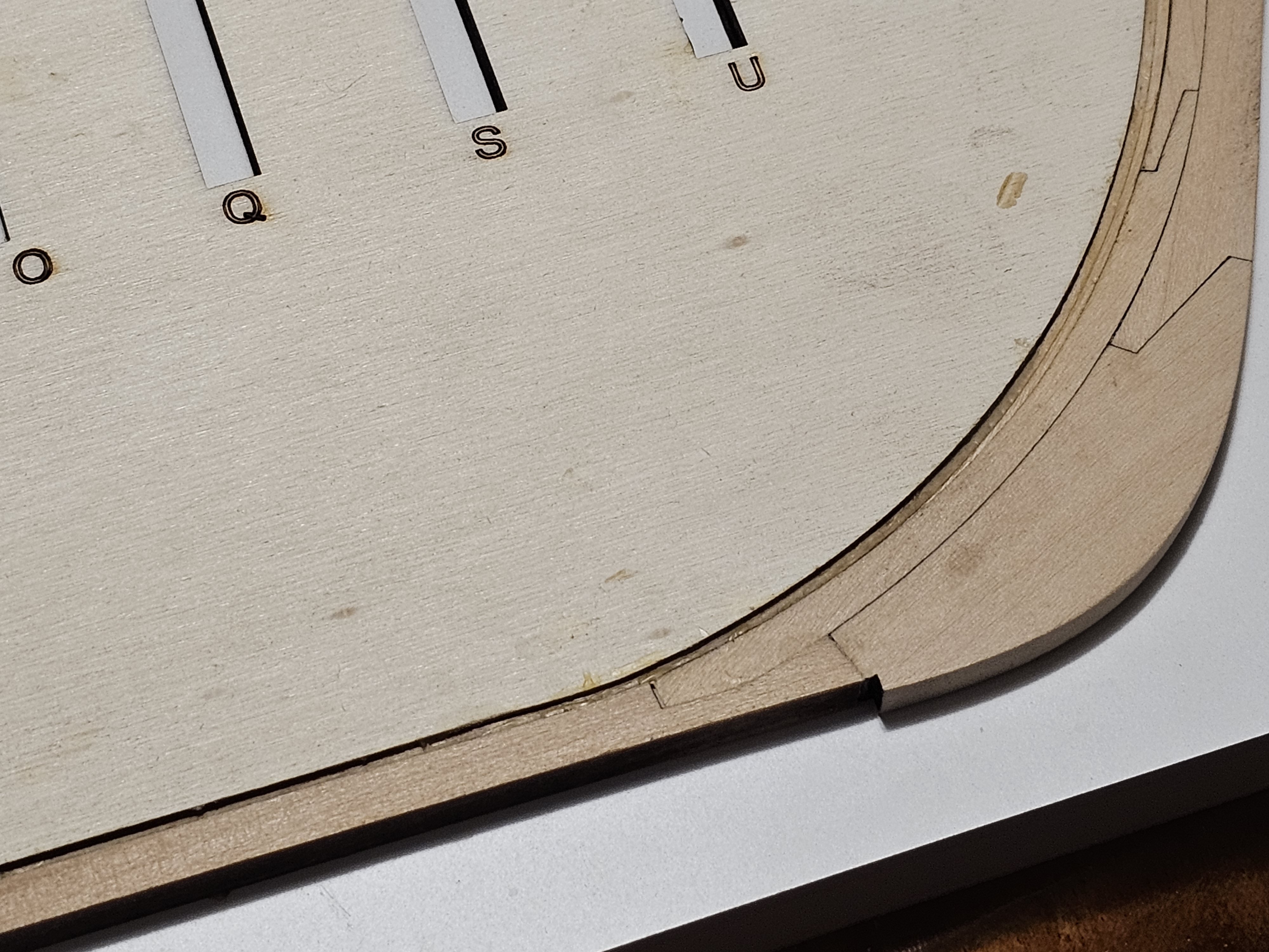
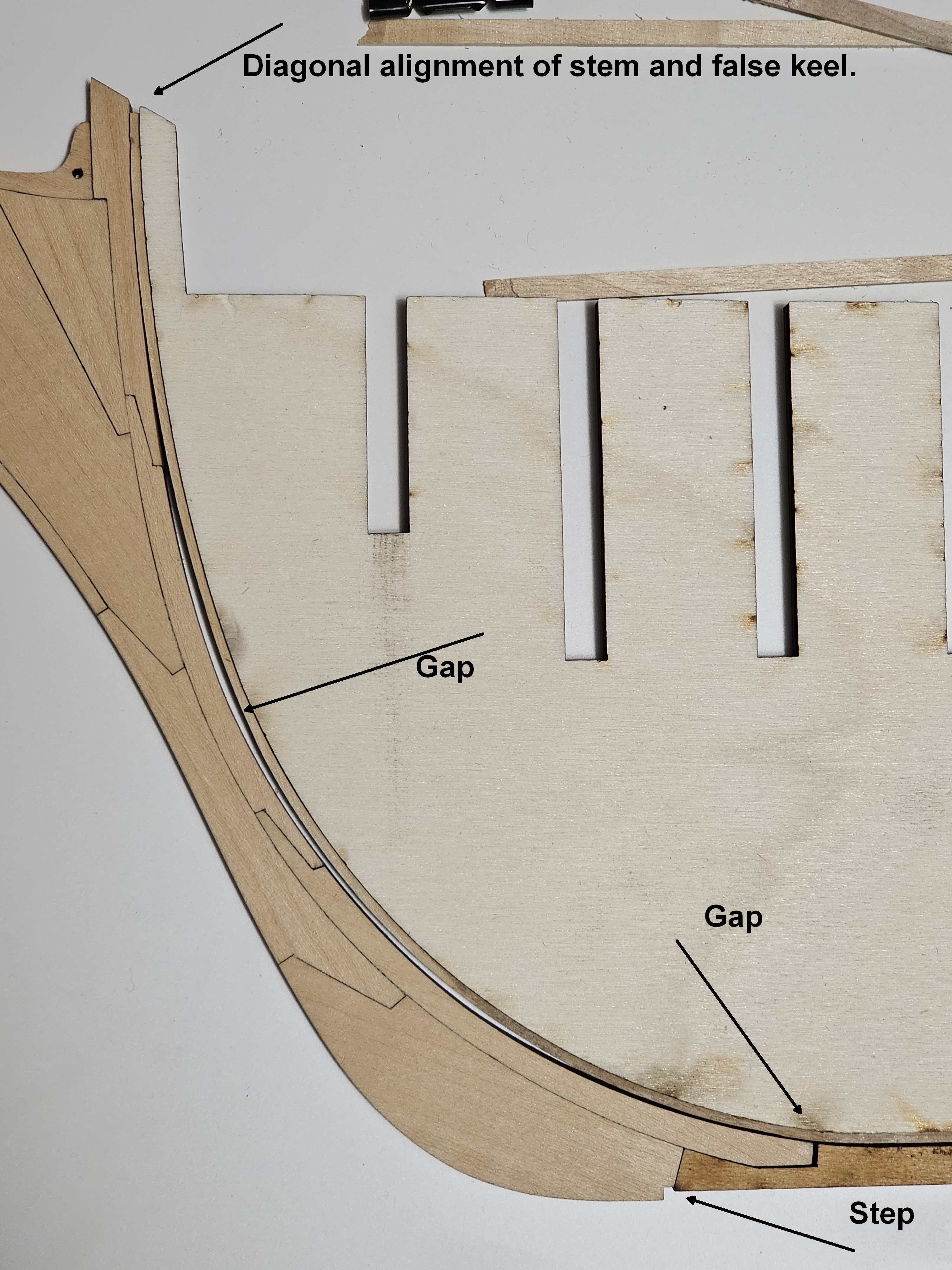
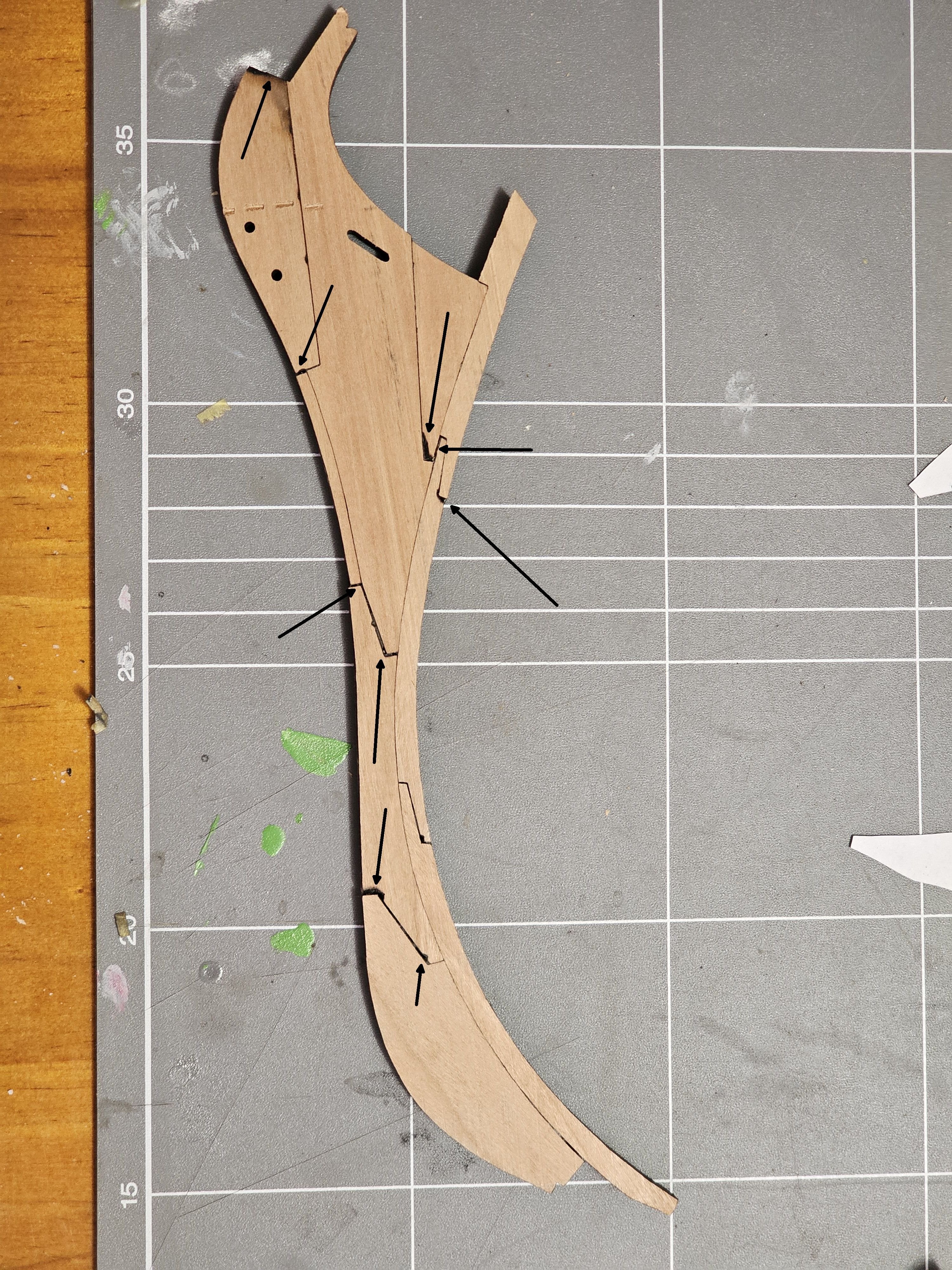
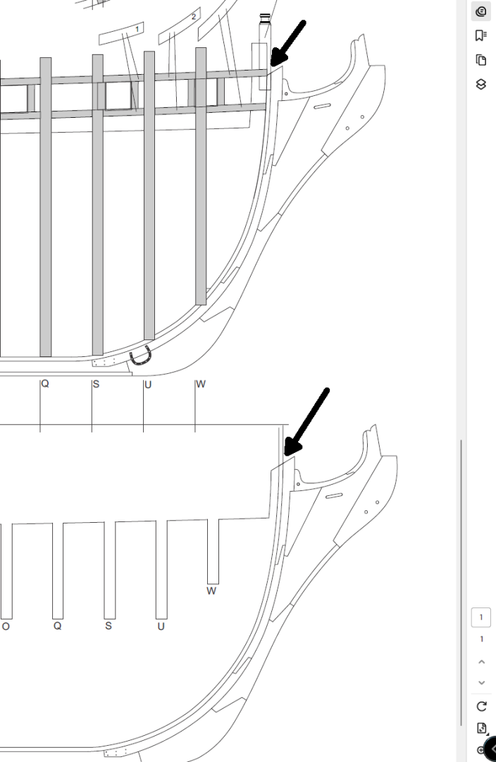
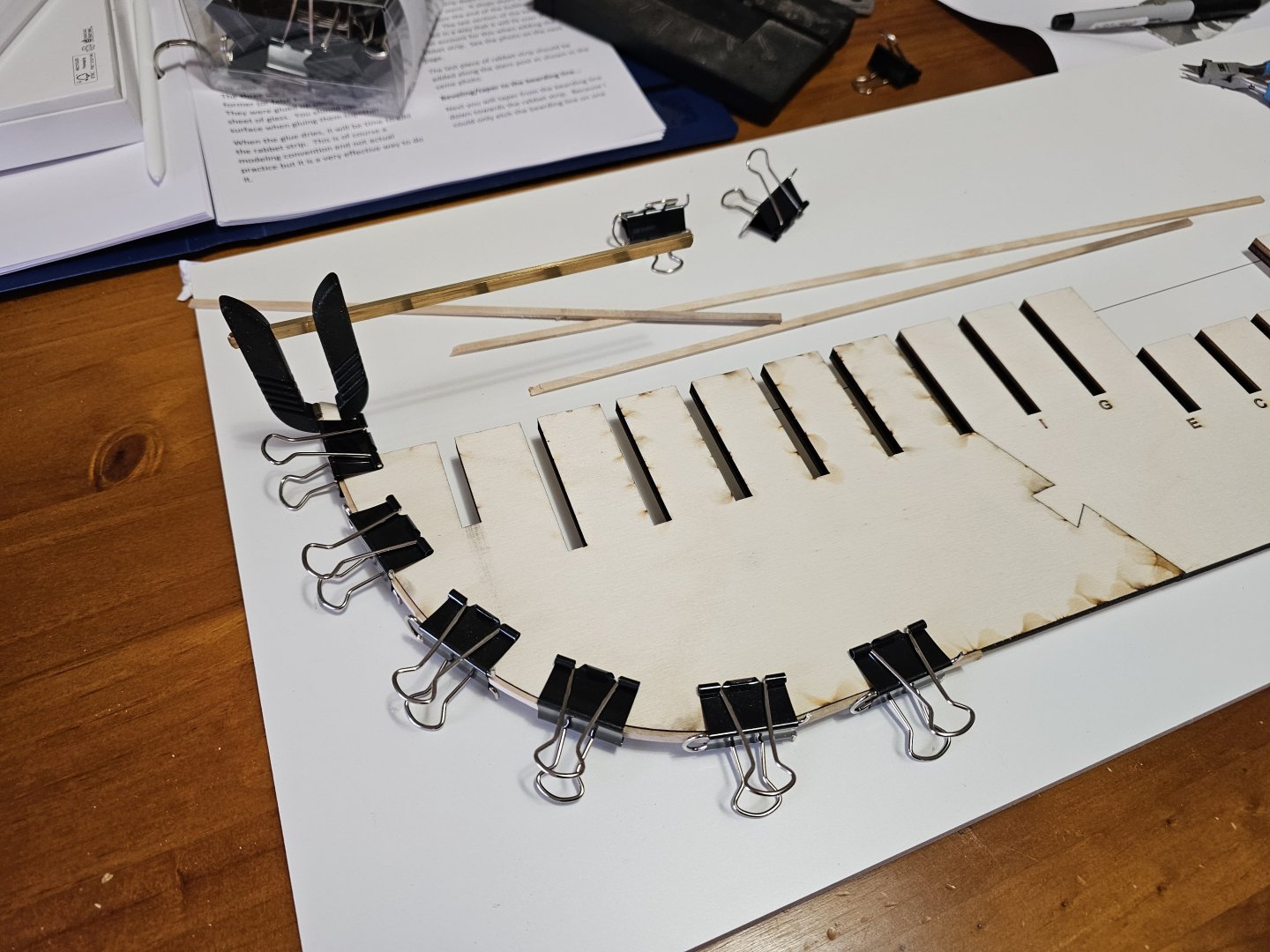
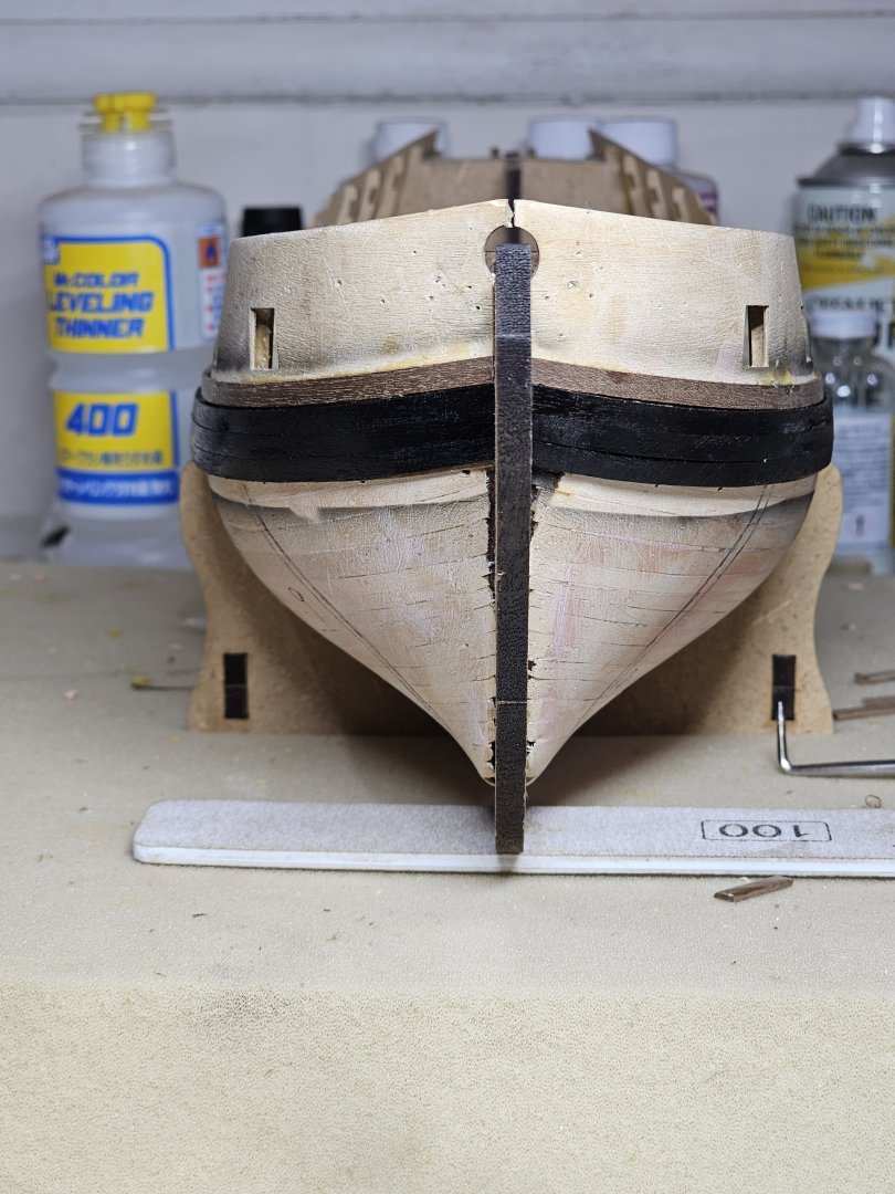
Morning all, Work slowly progressed the last few days. I have gotten myself a melamine building board and have started to glue the rabbet onto the false keel. I used my Byrnes table saw and Proxxon thicknesser to make the 4mm x 1.56mm (5/32nd x 1/16th) strips for the rabbet. The rabbet eventually came out to 1.53mm thickness. I used an Iron to heat the strip and clamped in place whilst it cooled and set with a curve. With the rabbet in place, I positioned the stem and the keel piece #1in position to check for fit. As can be seen in the 1st image, both ends of the stem are in contact but there is a roughly 0.8mm gap (perhaps more) in the centre. My question then is how to rectify this? 1) Do I remove wood from the top of the stem allowing the bottom to act as the pivot? 2) Do I remove equally from the top and bottom realising that this will affect the stem to Keel #1 piece. If you look carefully at the stem to keel #1 joint, you will see there is a flush fit everywhere bar the stern most vertical joint where there is a 0.8mm gap. Also note the false keel step on the stem and keel #1 piece joint. Thoughts on how to proceed would be appreciated.

-
All of the joins were as supplied in the files. I calibrated the cut power as best I could. I have not yet investigated the kerf or taper of the laser. The machine though apparently has a 0.15mm kerf. The 11 pieces of the stem fit together snugly after cleaning the tabs that hold the pieces in place after cutting. I am now in the process of assembling the keel and frames. I hope to have an update here soon.
-
Thank you. 😊 I should be so lucky the rest of the build will be like this. A wood worker I am not. 🤣 Not all my photography is like this. I do have pro equipment but sometimes I find the Samsung phone does the job for in progress shots.
-
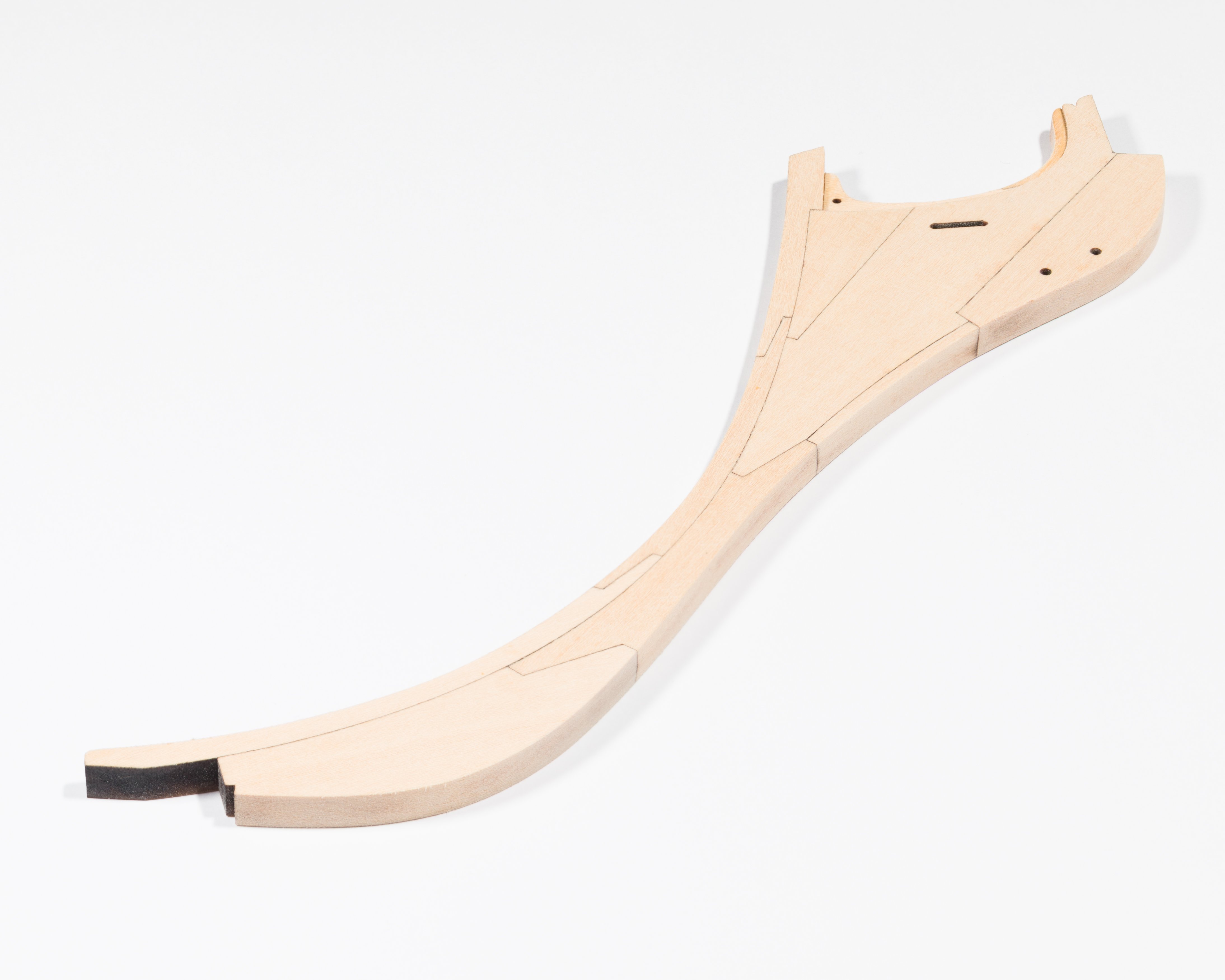
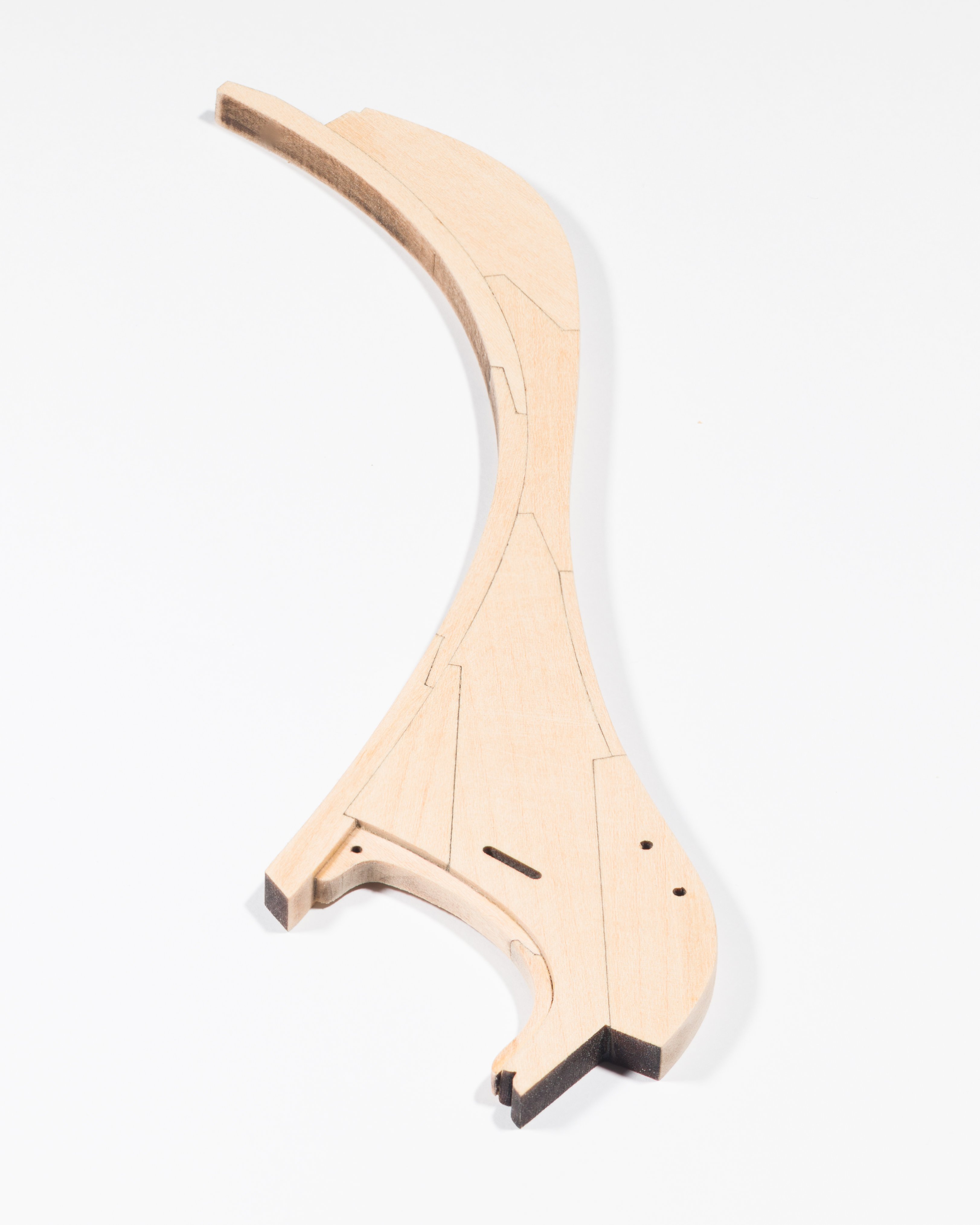
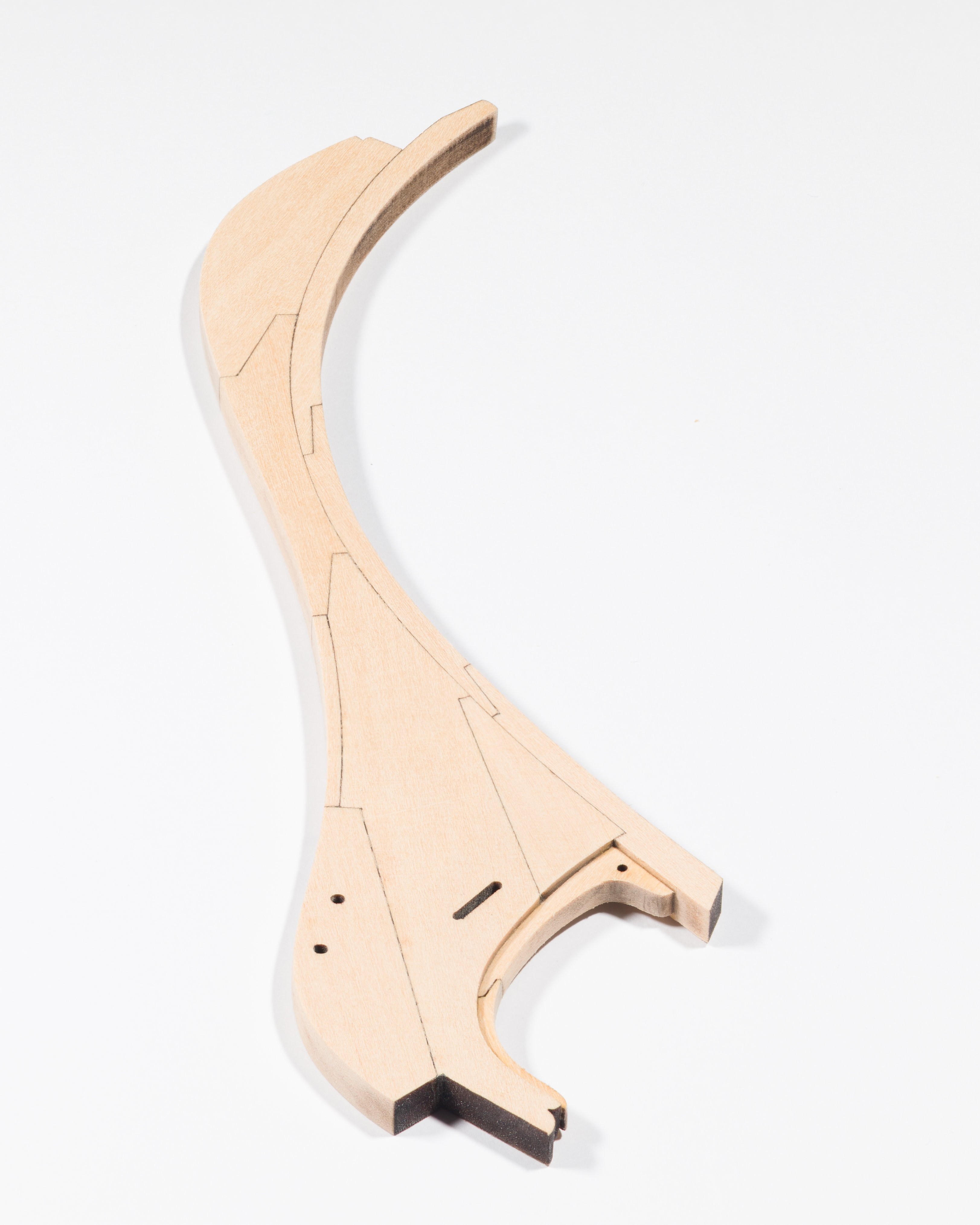
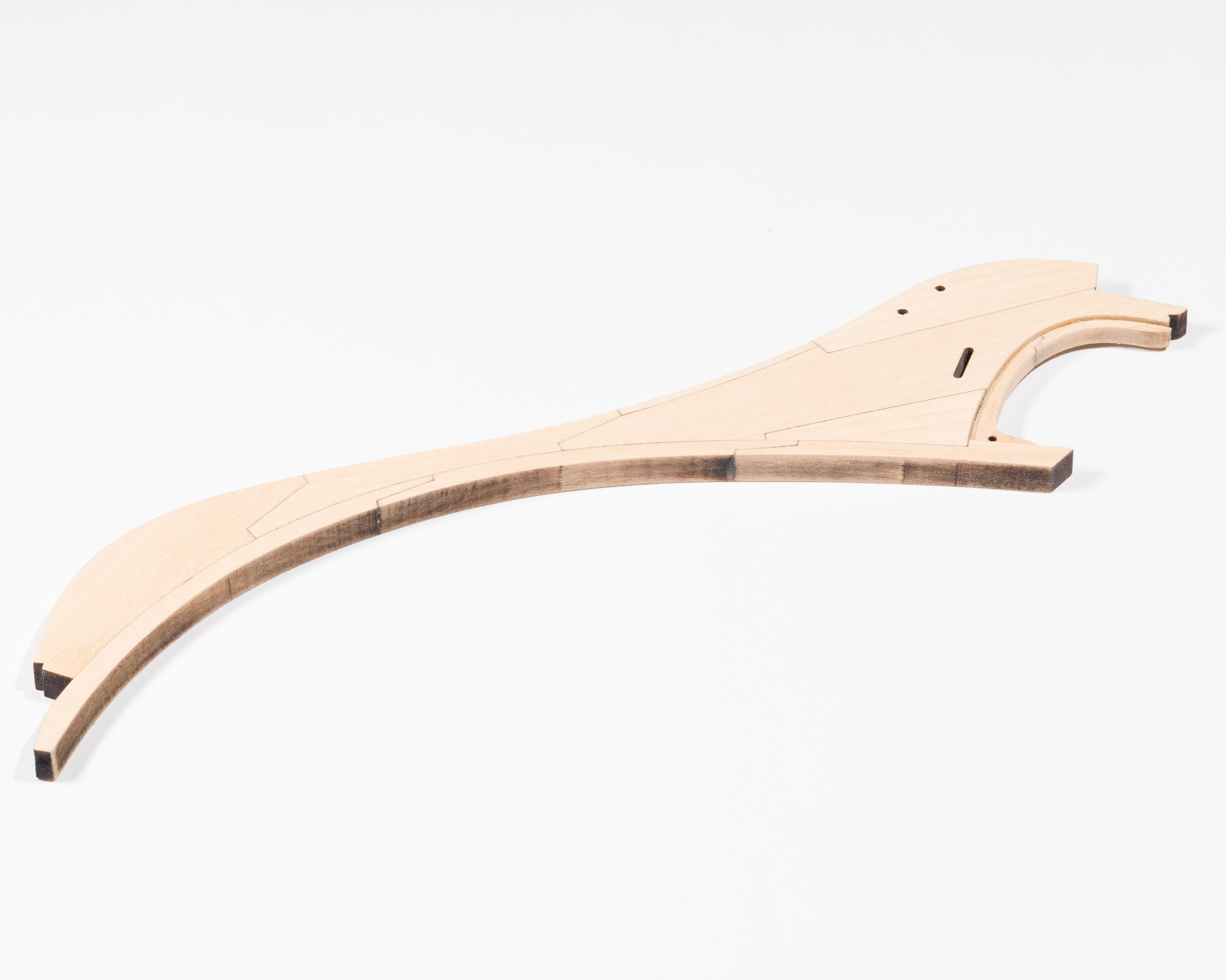
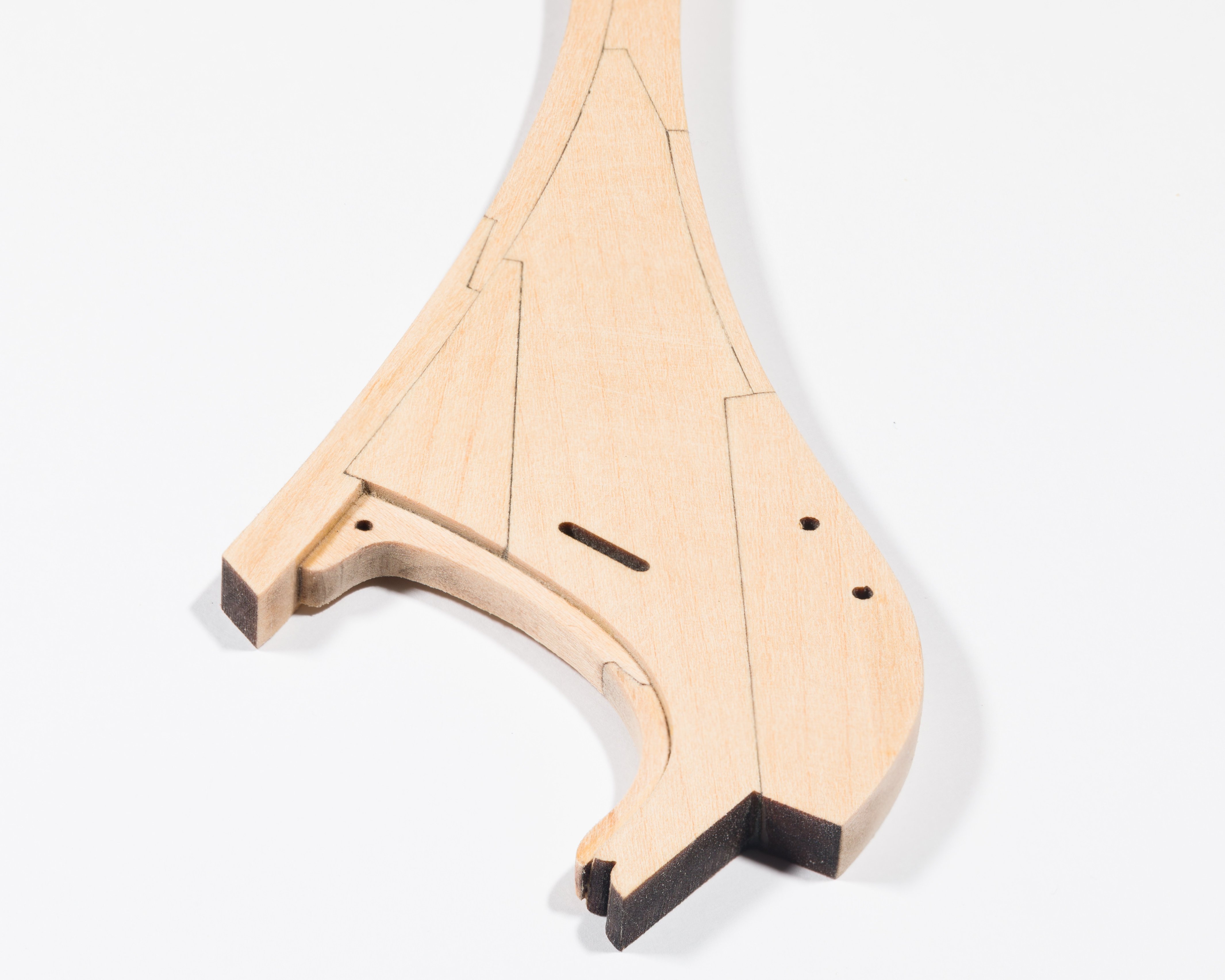
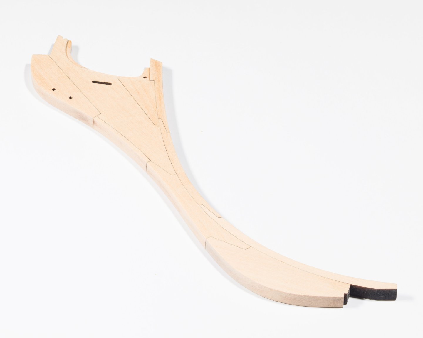
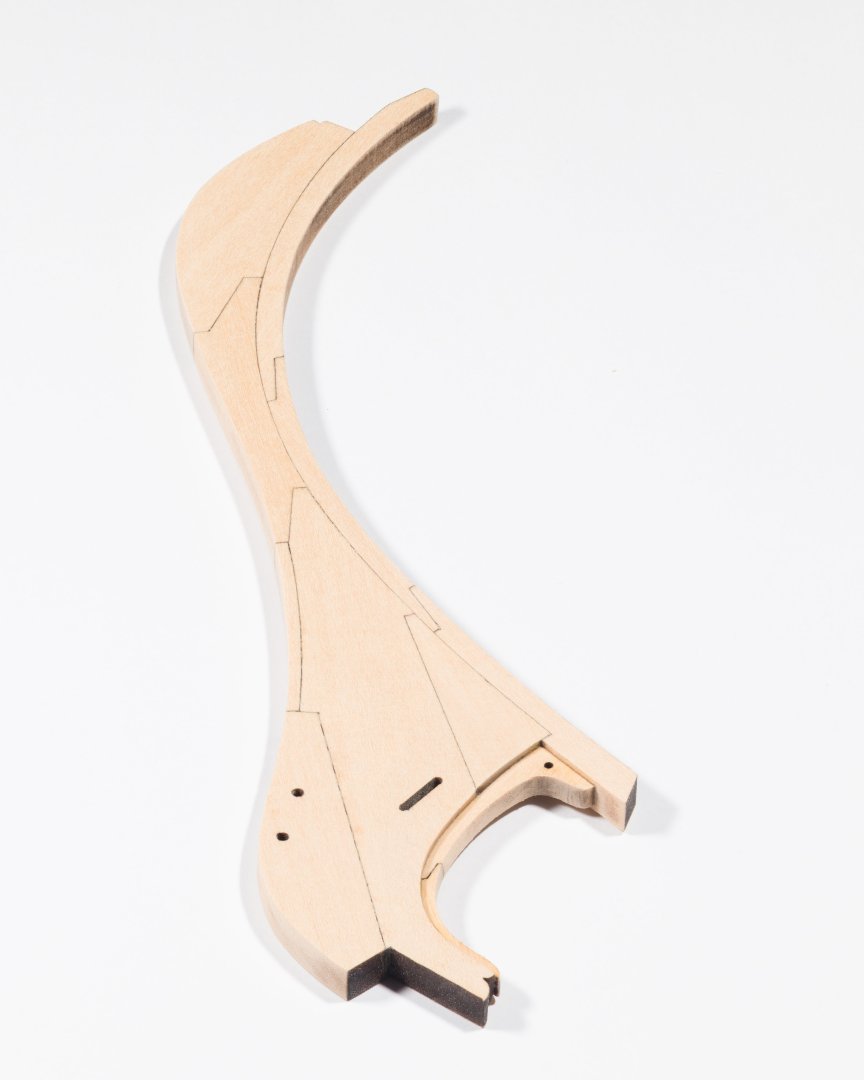
I have assembled my 3rd version of the stem after having issues with the laser using too much power.. I used some Sassafras that I had and thicknessed 3 300mm x 80mm x 6.35mm planks with my Proxxon DH40 thicknesser. I used one plank to calibrate the lasers power to the material and then cut the pieces out on the 2 remaining planks. I had taken the original files and used acrobat and illustrator to make new cut files that would fit the plank sizes I had. I may use this as the final version of the stem.


-
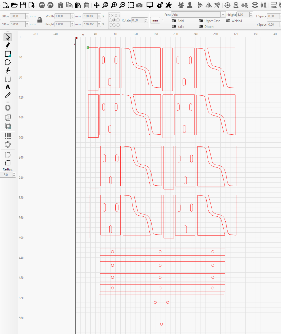
G'day Frank, Thank you for that. I have joined a makers space nearby that has woodworking, metalworking, 3d printing, and 2 laser cutters in the space that I can use. The two laser cutters are 1 ) Trotec Q500 running Ruby with a bed size of 1,300mm x 900mm and a 120 watt laser. 2) Thunder Laser Nova 35 running Lightburn with a bed size of 900mm x 600mm and an 80 watt laser. I have used both. I found the Nova 35 running Lightburn much easier to use due to the Lightburn software. I need to be inducted though in 2 weeks time before I can do it myself. Currently, I need someone over my shoulder supervising. My plan is to use Poplar 900mm x 600mm 6mm ply that I can source locally for the bulkheads and other things requiring 6mm ply. For the 1/4" stem etc I plan to use either Poplar or Huon pine slabs that I can rip to thinner boards with their bandsaw. Once that is done, I will run each boards large face flat on the planer. Once they are all done, I shall then flip them all and run each board through the thicknesser to get to 1/4" thickness. I have downloaded the full Creative suite. I split the bulkheads into individual pdfs. Then, in Illustrator I created 2 documents sized 900mm x 600mm. The first document has the 3 keel pieces and the first 14 bulkheads all fitted into the document. The 2nd document has the remaining bulkheads. In Chapter 1, all of the 1/4" pieces were placed into a new document sized to minimise the waste of the Polar or Huon. The MDF 6mm cuts were ok, some slight scorching on the rear. Having talked to a few users in the makerspace I get the feeling they use just the material defaults in Lightburn and are happy with the results. Me though, I have looked into the software and there is a lot of tweaking that can finetune the laser to the particular material and thickness. Once I am inducted, I shall do some calibration tests for the 1"4 Huon or Poplar and 6mm Poplar ply so that I will get good, consistent cuts by the laser. I will also be checking to see if the laser is set to allow for the kerf of the laser. Once that is done, I will then run the final 1/4" and 6mm pieces through the machine. Everything I am doing so far is to build my experience with the software and to eliminate as much waste as I can. I will do things myself only to eliminate the issue you raised or buy things I need that I cannot manufacture myself off Chuck. .
-
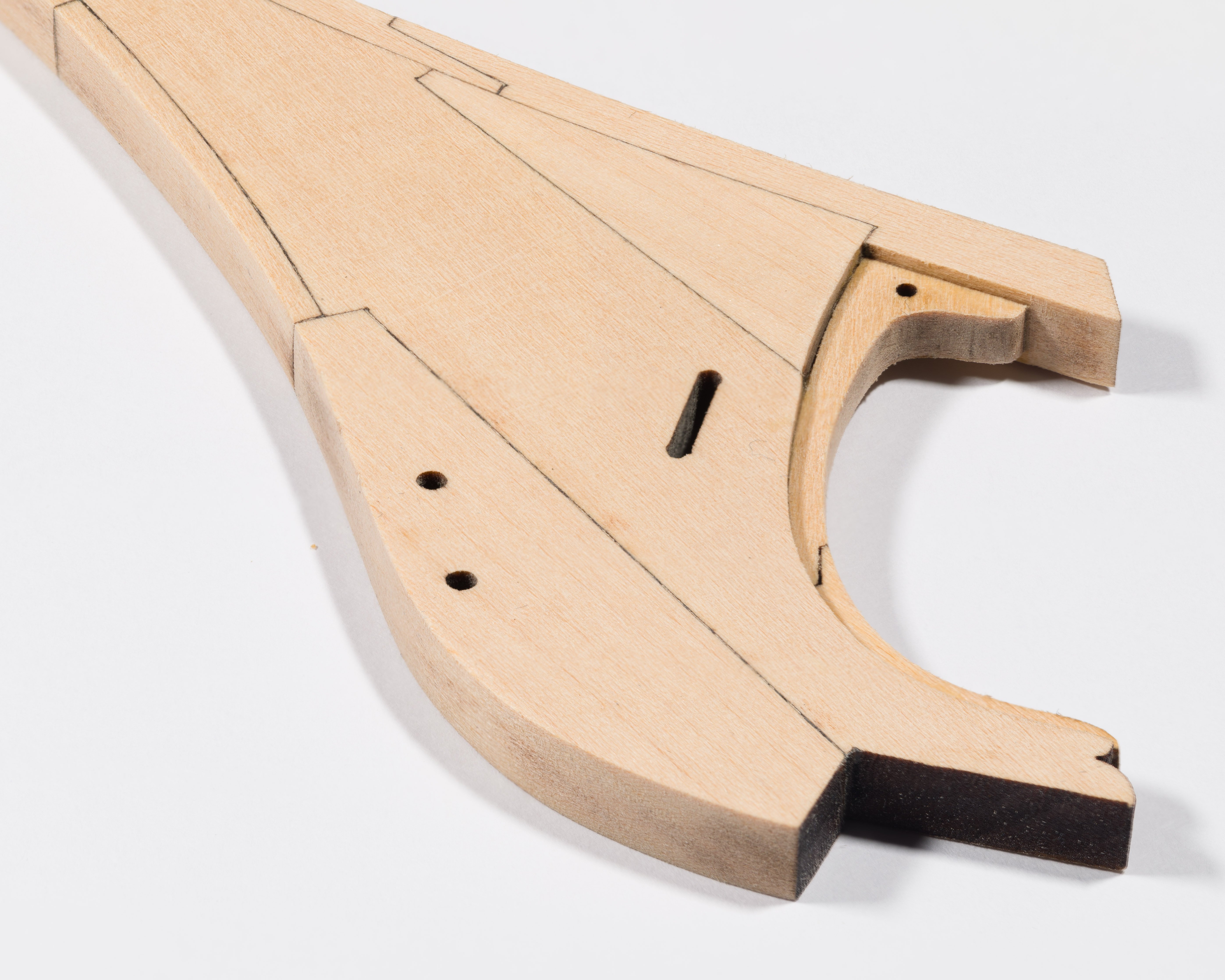
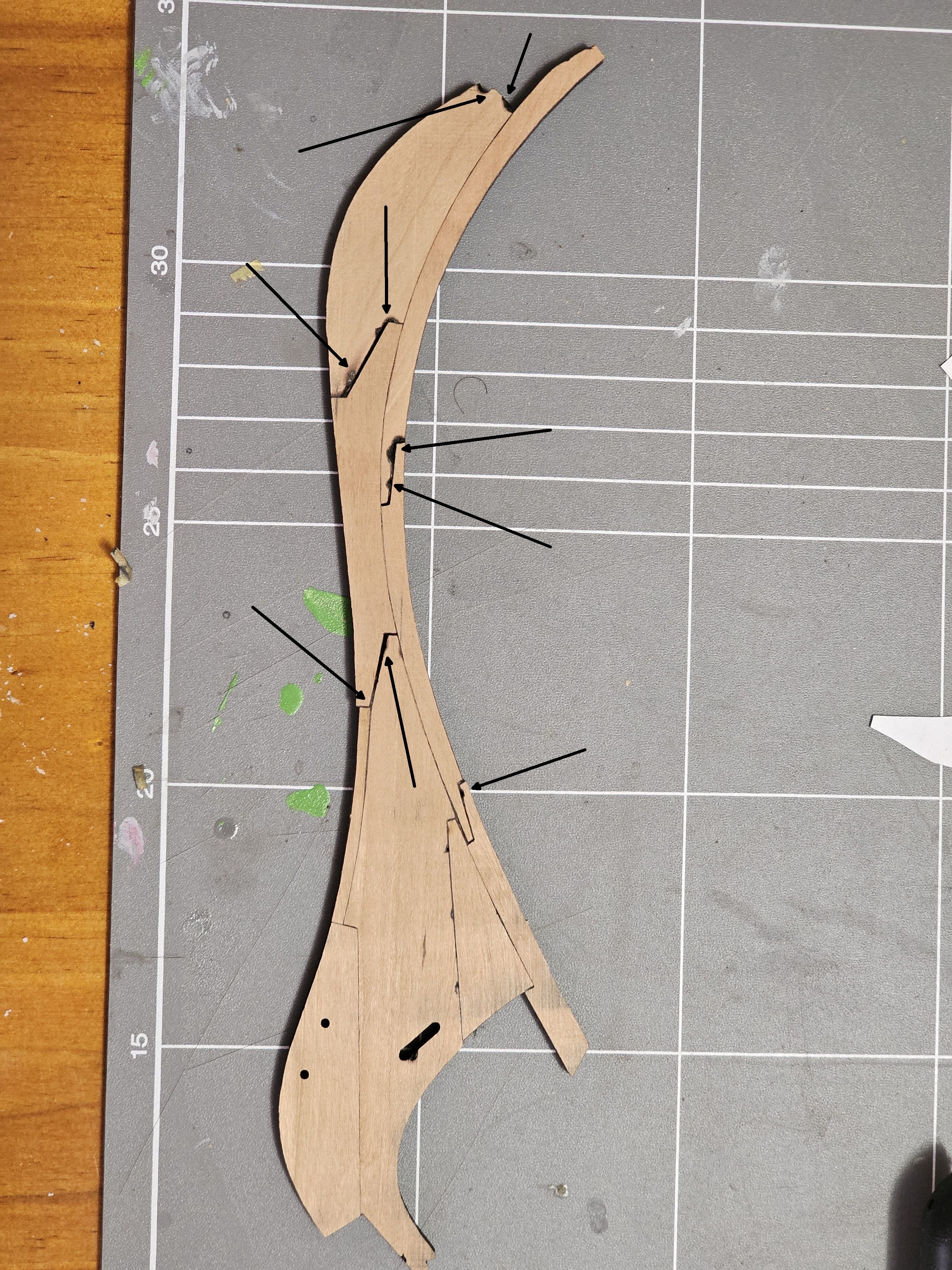
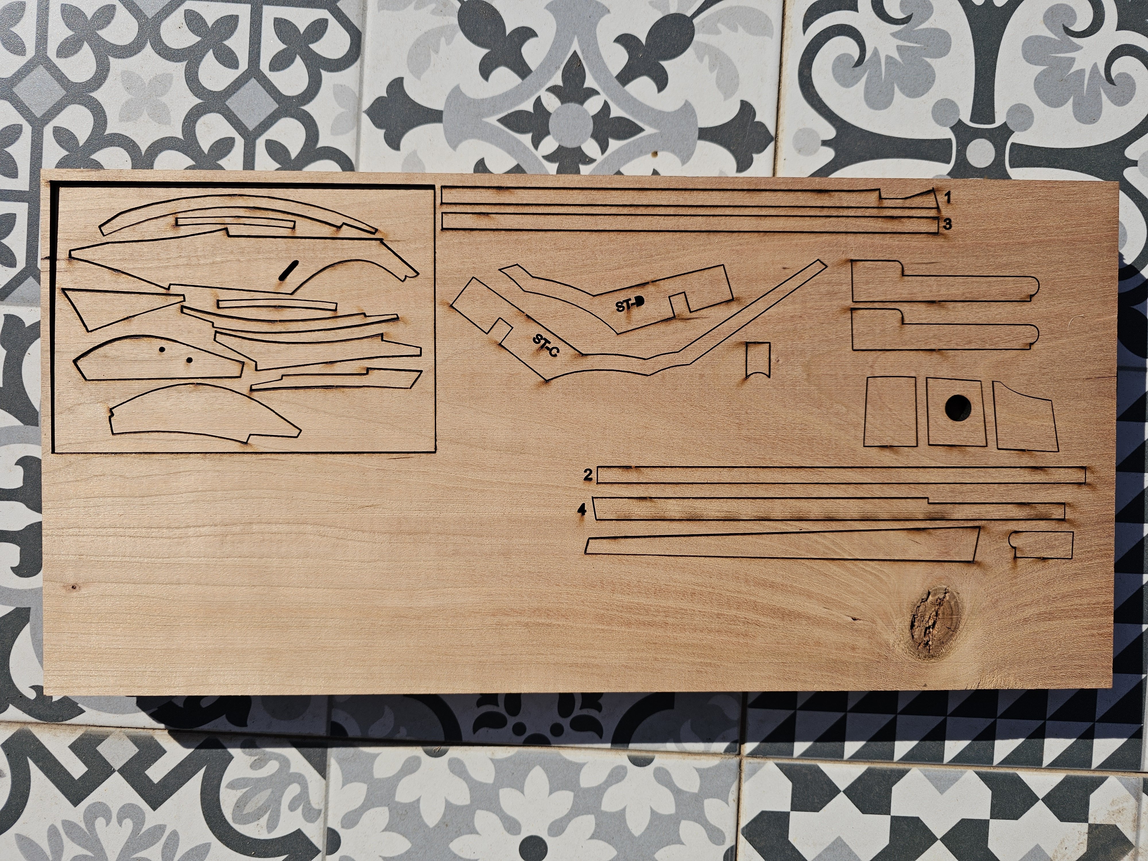
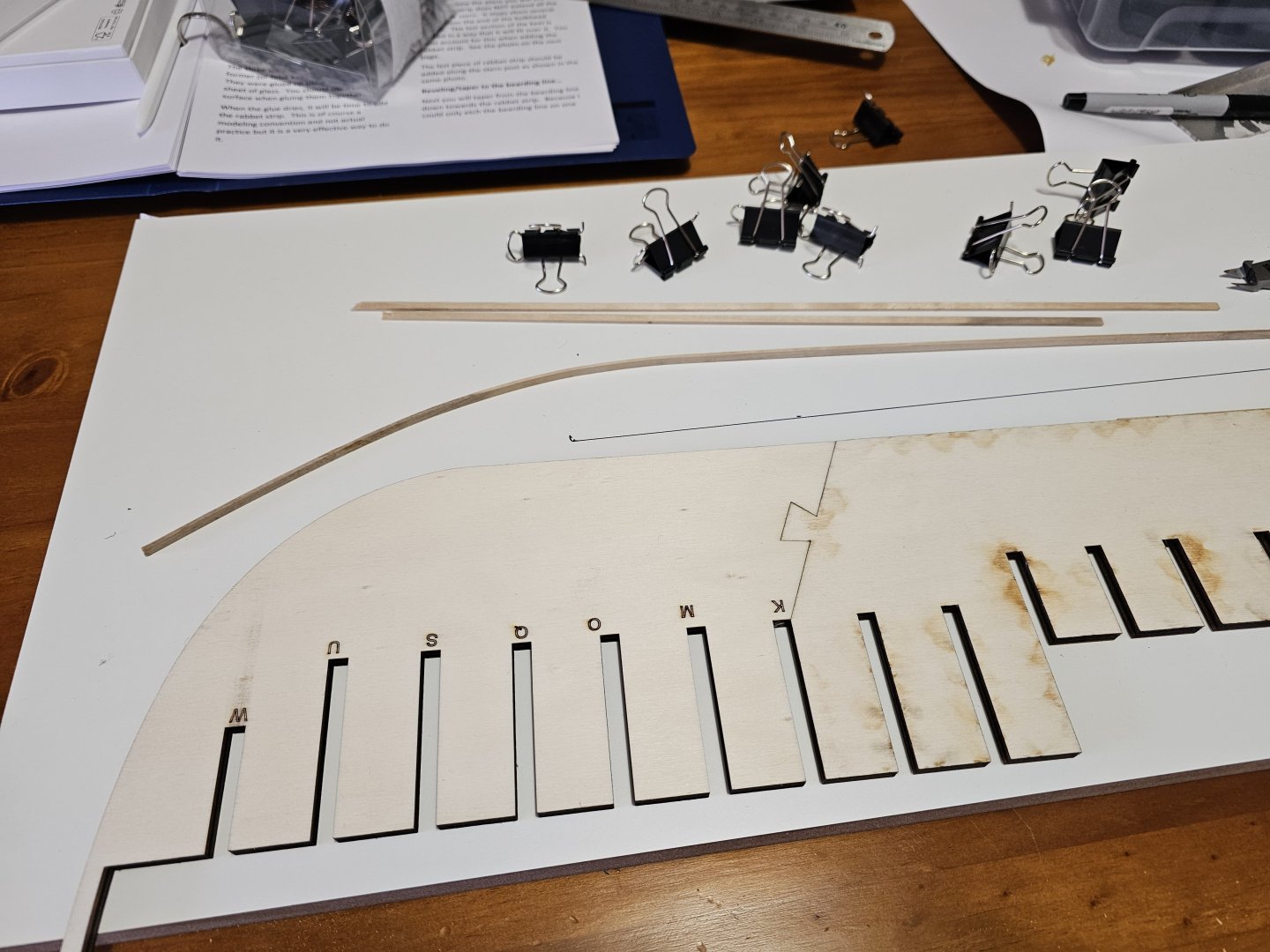
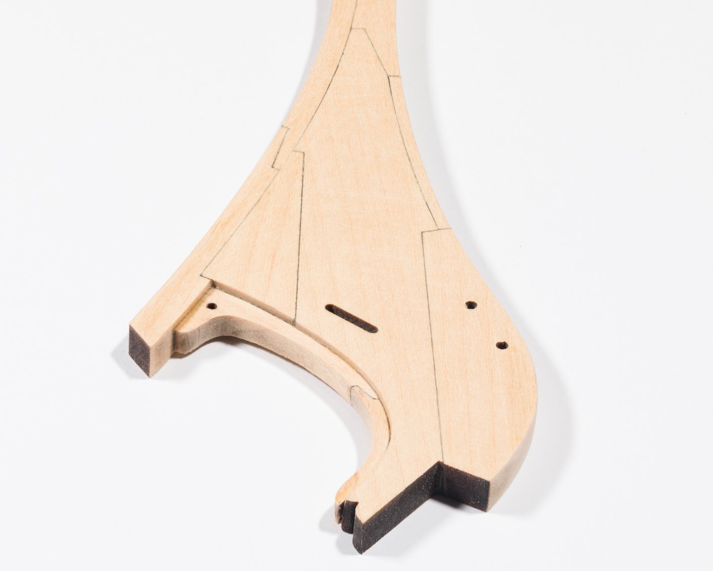
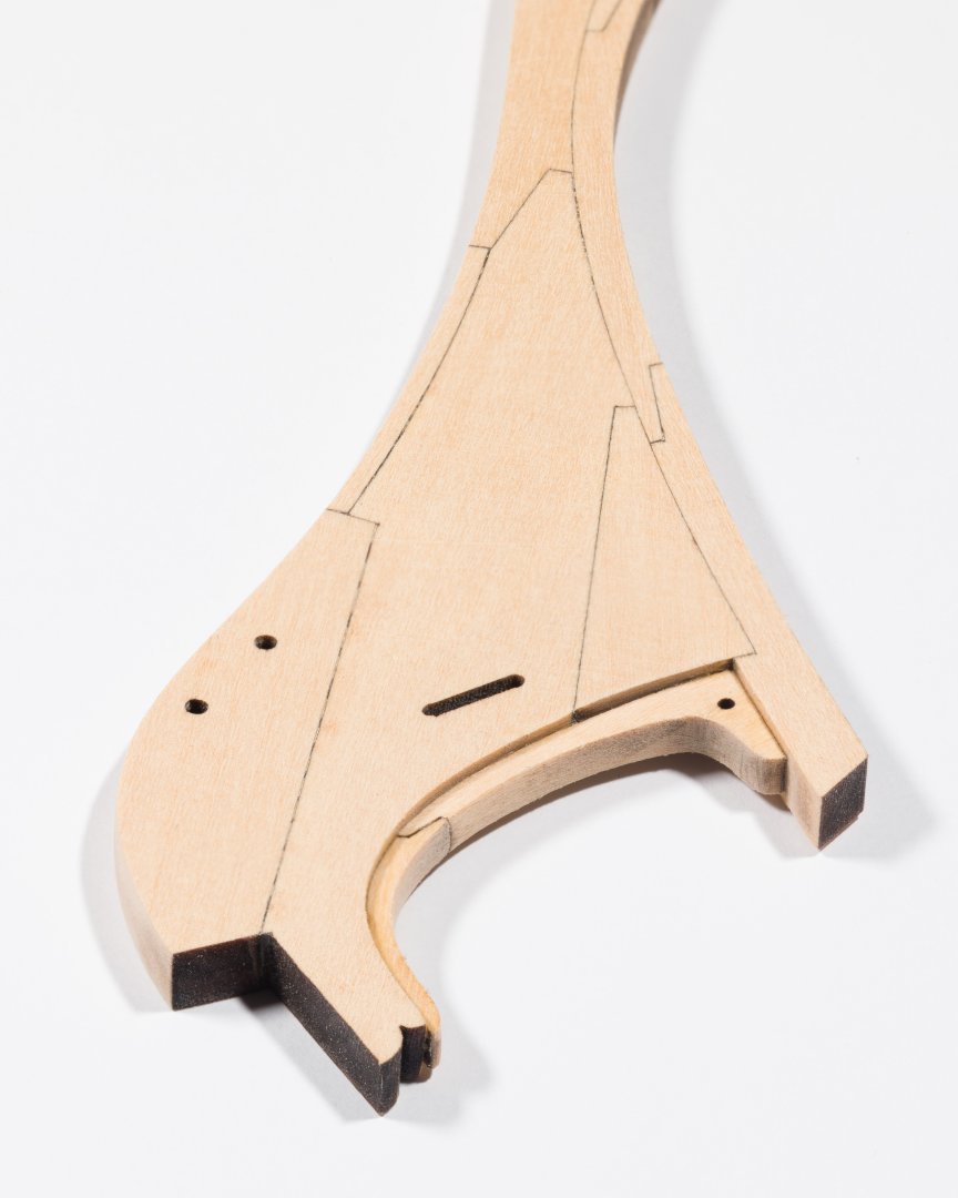
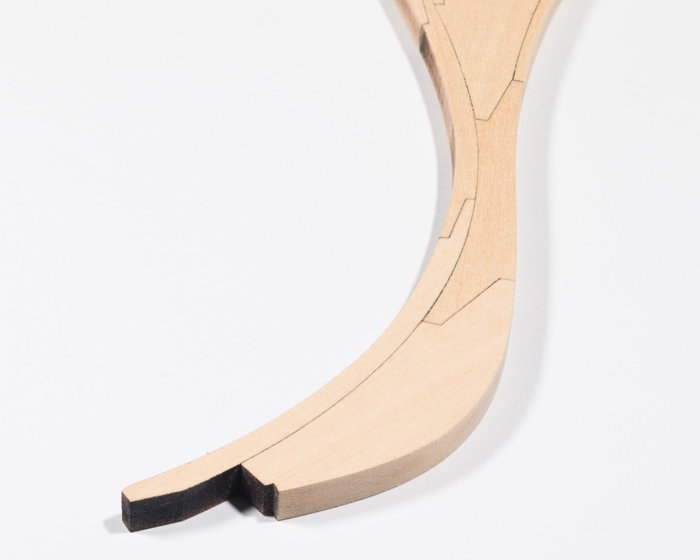
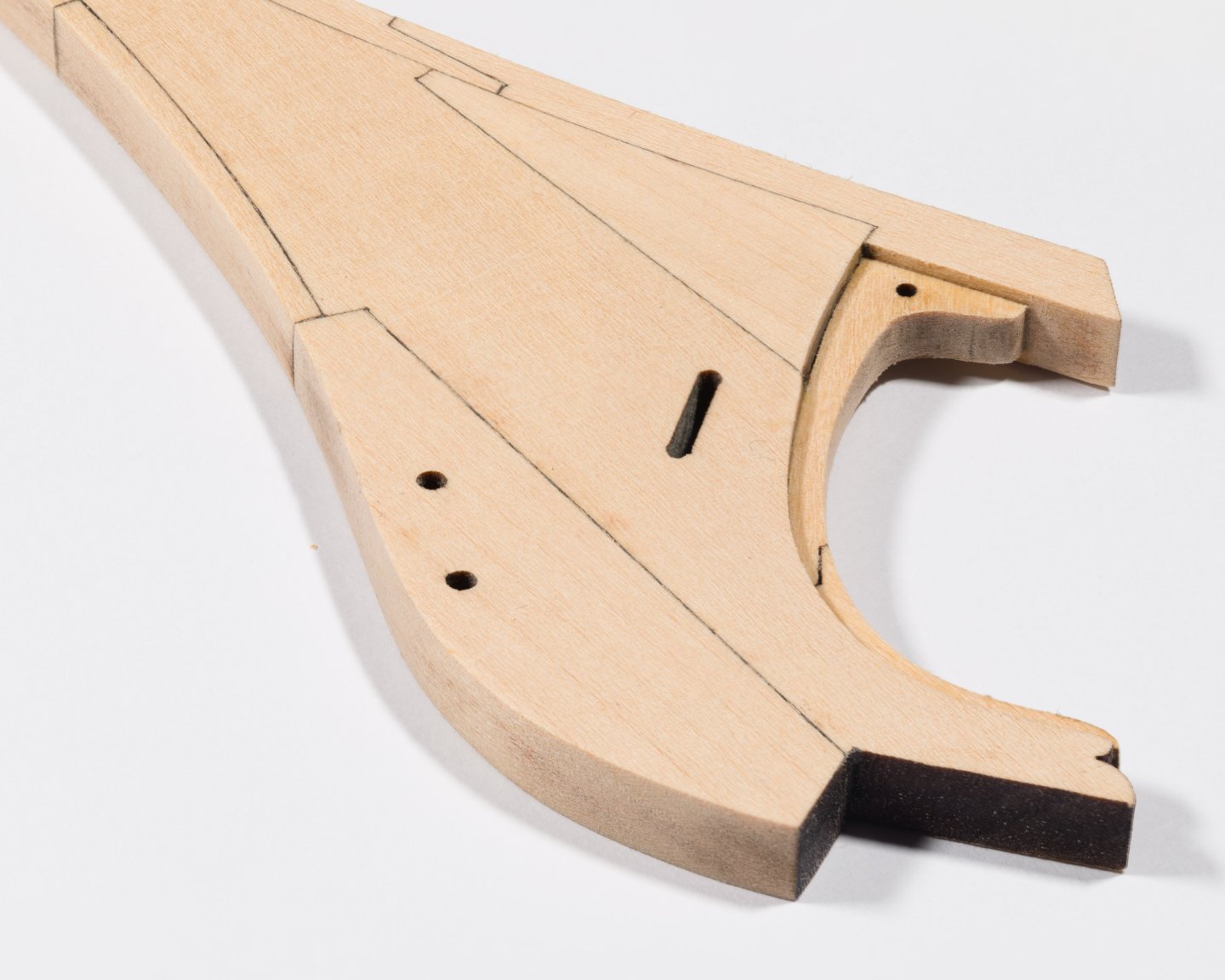
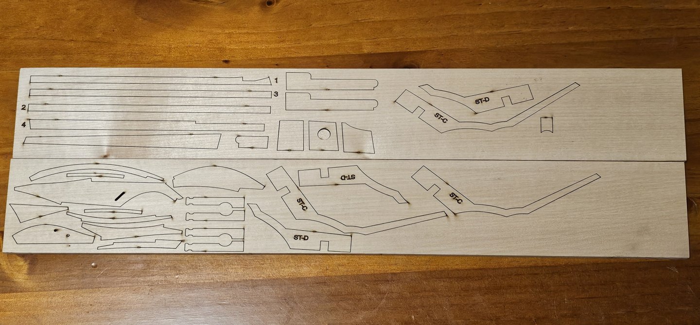
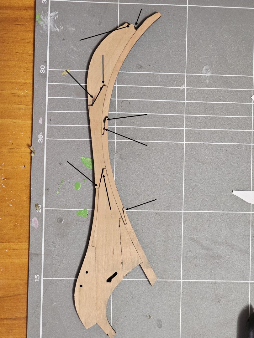
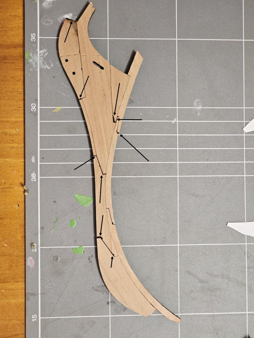
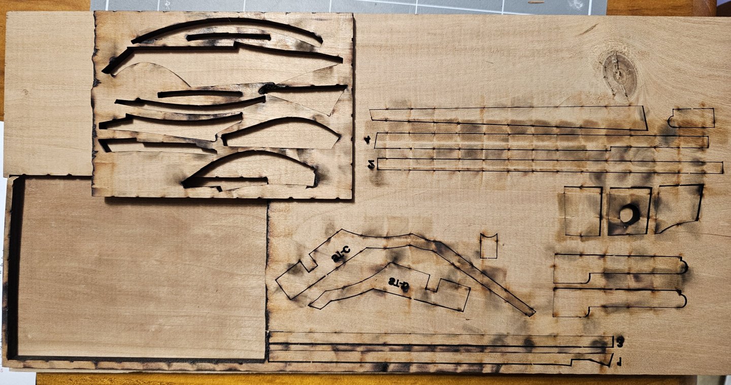
I spent some time gluing up the parts. One thing I noticed whilst I was watching the laser cut was that around 2 thirds of the lines would cut with a single pass of the laser. These resulted in nice clean cuts. However, the remaining lines each had up to 10 or more passes which resulted in scorching and small holes from I assume reflections of the aluminium grid it was resting on as the beam repeatedly passed over the same path. As can be seen in the two images, some of the joints are spot on. However, there were other joints where the wood had been scorched away from repeated passes of the laser. This resulted in gaps in some of the joints. I have highlighted problem areas in the two images. The scorch mark are obvious in the images I posted above. That is the top side view of the board. The underside was much worse. I suspect the person operating the laser (I wasn't inducted) did not know how to correctly setup for the cherry. I did not notice a setting in the software for wood except MDF or Plywood. I shall be modifying my approach to this piece. I used 1 1/4" cherry and after cleaning the scorch marks and correcting a very slight bow I induced from the glueup, To glue up I will be using pins and a board to hold the pieces flat whilst drying. This attempt though I did not. (I used my Proxxon Planer then Thicknesser to flatten and clean up both sides.) I ended up with a flat stem at 210 thou instead of 250 thou. It shall be remade and I am considering changing from Cherry to another wood that I can source in Australia. Poplar or Huon Pine. I have also attached an image of two other laser cuts I made on the same wood panel. This show the underside though with the scorching. Unfortunately I did not get an image of the stem panel underside.
-
A little bit of progress on Pegasus. The wales were sanded flush to each other, masked and then tamiya flat black with mlt to thin was sprayed on the wales. There is also one row of the 2nd planking above the wales on both sides. I have yet to decide how to trim the rear of the wales as I don't yet understand the run where they should finish and what shape they should be.

- 16 replies
-
- 2
-

-
- Pegasus
- Victory Models
- (and 1 more)
-
Hi Everyone. I bought the plans and downloaded them several weeks ago. I was contemplating having Chuck send the starter kit to me in Australia. It seemed the easier way. However, I have chanced up a community makers space a few miles away which provides access to laser cutters, and woodworking machinery that I don't have. I bought a block of Cherry a while ago and thought I would see if they could assist with sizing it into 3 x sections by ripping the 1 1/4" slab on a bandsaw. The bandsaw was waiting a new blade so they used a table saw. I sized the slices to 1/4" on their thicknesser. I then used 2 of the pdfs I had for the stem to test out their laser cutter. It has a bed size of 1300mm x 900mm. My little piece was accommodated with ease. One question I have though regards the bulkheads and keel pieces. They are 1/4" ply. That size is problematic in Australia being a metric country. I can source 6mm or with some difficulty 6.5mm plywood. Both are fine? grades for exposed faces in furniture production. 1/4" though is 6.35mm. If I substitute the 6mm OR 6.5mm ply, what issues could be expected further down the build? Thoughts or workarounds?

-
I shall be posting updates as I go. I have a build log here. I am currently finishing the two layers of the 1mm x 4mm Wales in the kit. This is a problem area for me as I am trying to work out how the Wales finish and are shaped at the stern.
-
I think this method makes sense to me. It may be what I do on my next model.
-
Cheers for that, I am being flooded with information from youtube builds, a few of my books, and suggestions here. They all make sense. However, with this being my first build in 40+ years, I plan on this method to try and get just basic techniques down pat. I want to find out the shortcomings and then perhaps look at adapting what I did on this model and then adapt and modify what I did to the next model. I have seen 4 of Chucks videos on shaping the planks. Nice method but I do not have enough info at this stage to go further.
-
Hmm, I haven't noticed any posts. I shall do a search. Cheers for that.
-
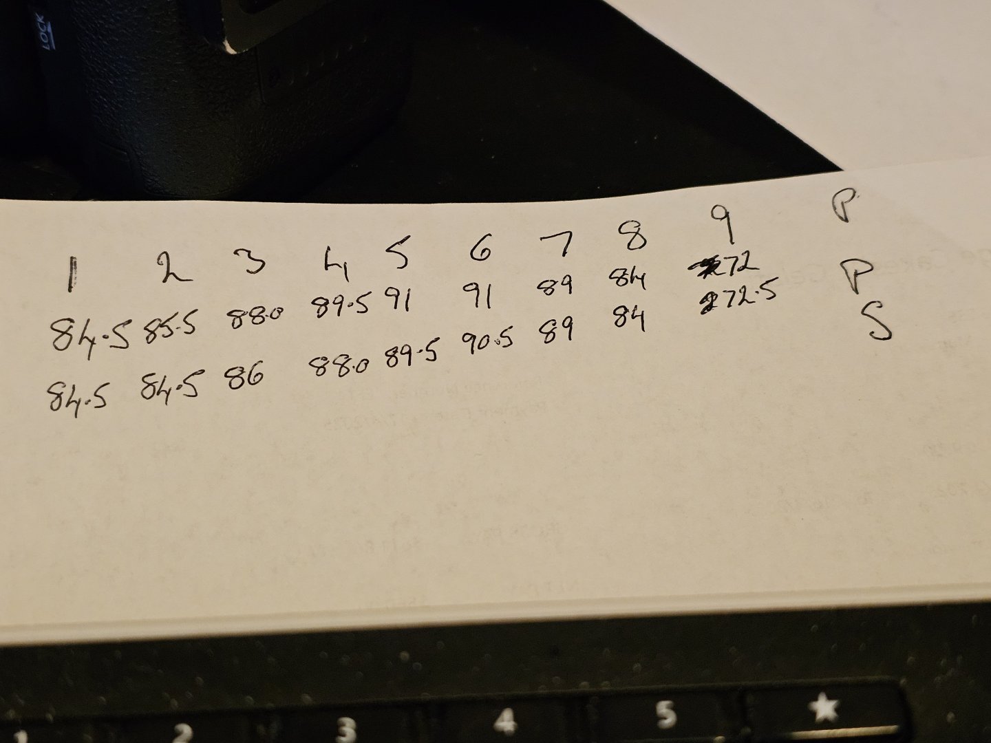
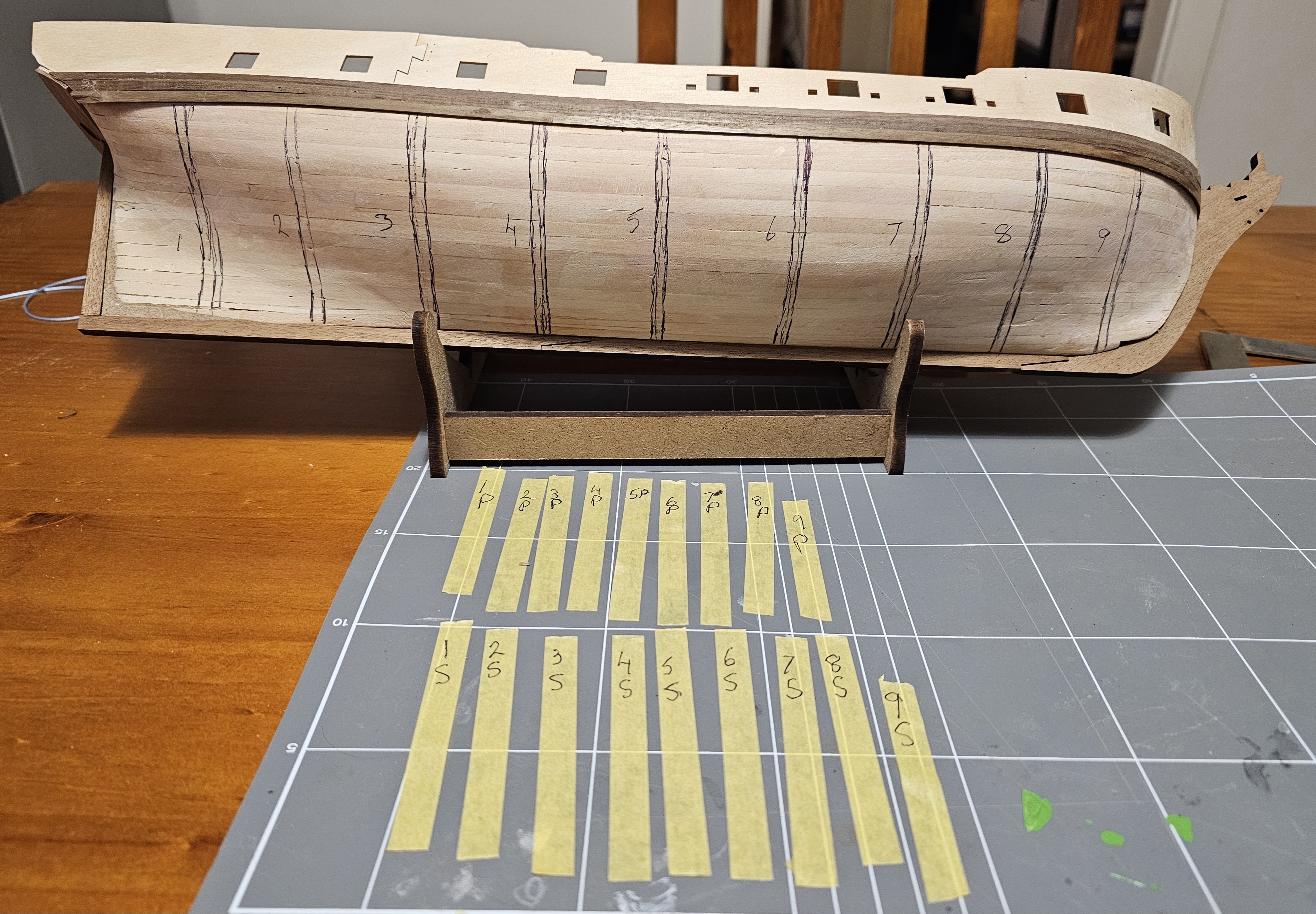
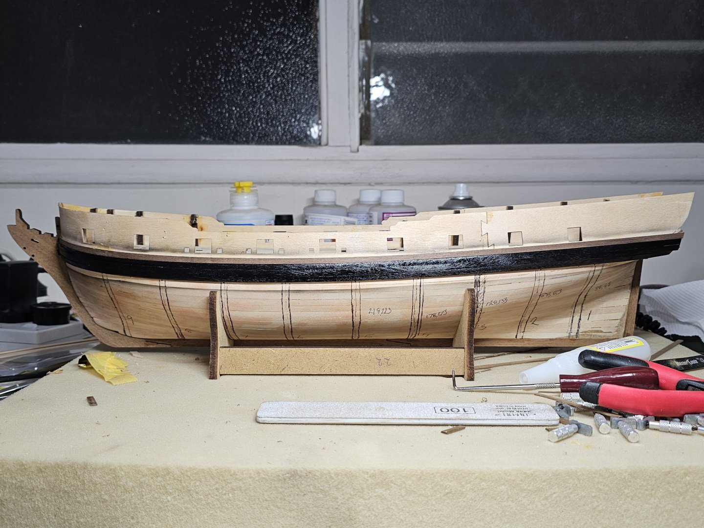
Thank you for that. I plan on doing 5 or 6 and then remeasure the gap and redo the calculations. The hull will be coppered but I do want to do the best I can to learn the techniques for when I do a hull that is not coppered.
-
Hi, I will be edge setting and bending the planks as supplied in the kit. I plan to lay down 5 or so planks each side to thee size suggested and then redo the planking calculations based on new measurements. I plan to redo that every 5 or so planks. Regarding the taper from the last bulkhead, I plan on assessing those as I fit each plank. I have yet to come up with a solution so will assess on each plank.
-
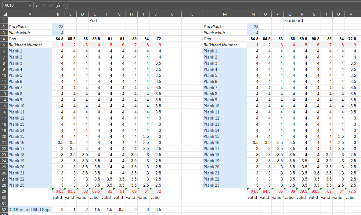
Evening, I am starting to get close to 2nd planking on my Victory Models HMS Pegasus. I think I have the idea of a planking fan sorted out. Does this look a reasonable way to approach this? Do the calculated tapers seem reasonable? I have seen other more involved methods but being my 1st wooden model in 40plus yrs, I think this will do for this one.