Dan DSilva
-
Posts
81 -
Joined
-
Last visited
-
 Dan DSilva reacted to a post in a topic:
Mary Rose by Baker - scale 1/50 - "Your Noblest Shippe"
Dan DSilva reacted to a post in a topic:
Mary Rose by Baker - scale 1/50 - "Your Noblest Shippe"
-
 Dan DSilva reacted to a post in a topic:
La Renommee 1744 by ChrisLBren - 1/48 - 2025
Dan DSilva reacted to a post in a topic:
La Renommee 1744 by ChrisLBren - 1/48 - 2025
-
ccoyle reacted to a post in a topic:
HMS Grogblossom c. 1700 by Dan DSilva - 1:128 - hoy - solid hull
-
Dan DSilva reacted to a post in a topic:
La Couronne 1635 by toms10 - 1:96 scale - POB
-
Dan DSilva reacted to a post in a topic:
Le Fleuron 1729 by Chris. - scale 1/72 - French warship from Delacroix monograph
-
Dan DSilva reacted to a post in a topic:
Le Fleuron 1729 by Chris. - scale 1/72 - French warship from Delacroix monograph
-
Dan DSilva reacted to a post in a topic:
Le Fleuron 1729 by Chris. - scale 1/72 - French warship from Delacroix monograph
-
Dan DSilva reacted to a post in a topic:
Le Fleuron 1729 by Chris. - scale 1/72 - French warship from Delacroix monograph
-
JacquesCousteau reacted to a post in a topic:
HMS Grogblossom c. 1700 by Dan DSilva - 1:128 - hoy - solid hull
-
Dan DSilva reacted to a post in a topic:
Mary Rose by Baker - scale 1/50 - "Your Noblest Shippe"
-
Dan DSilva reacted to a post in a topic:
Mary Rose by Baker - scale 1/50 - "Your Noblest Shippe"
-
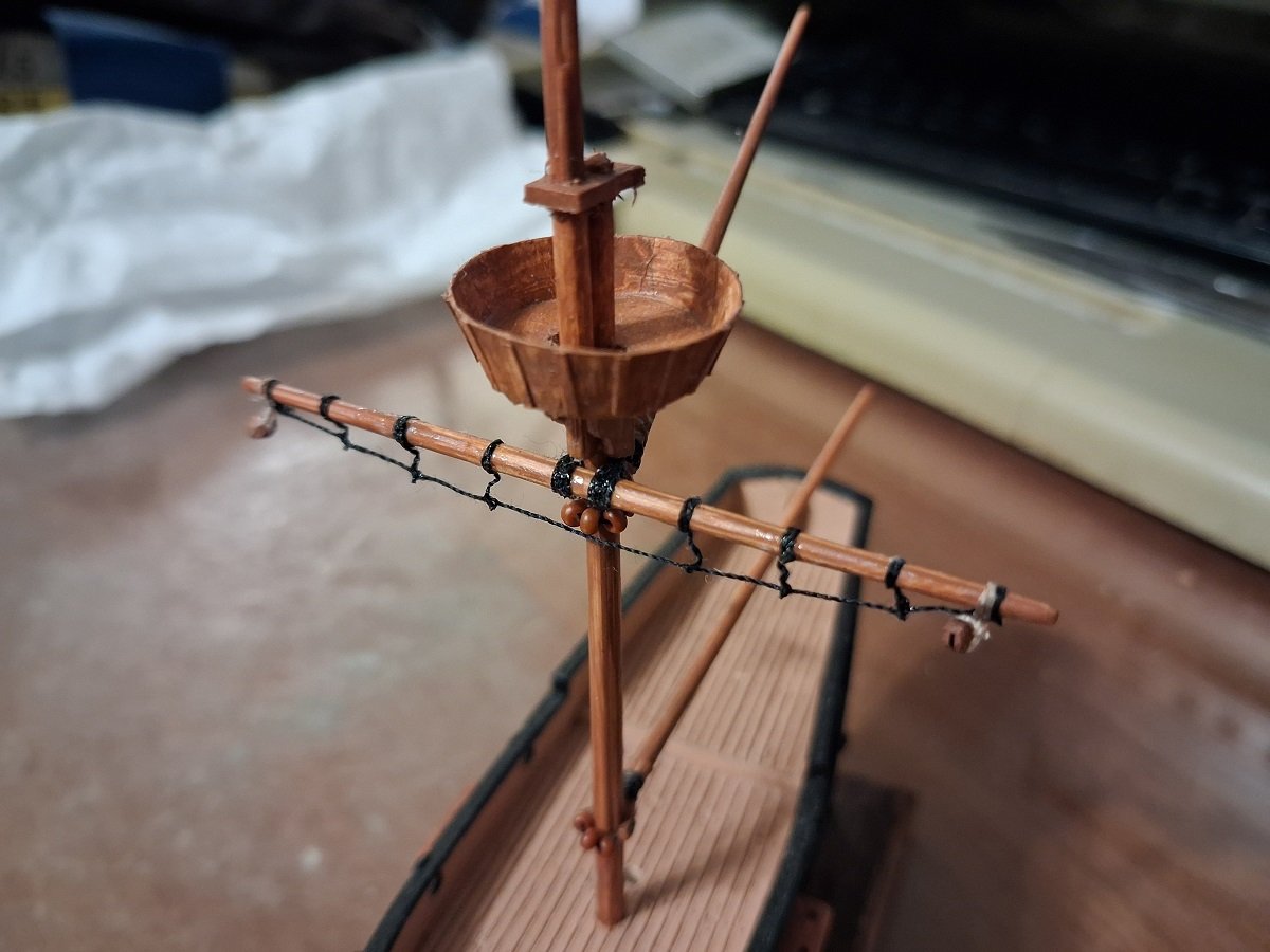
 The crossjack lift is in place, but I managed to break both the glued cardstock spar yokes in the process of stropping the blocks (you can see the white lines where they cracked). Wish I could think of a stronger construction for them -- I tried making some out of thin birch plywood, but it was too splintery for something so tiny. I know the lift should be attached to the mainmast, but there's no room to fit the line between the mainmast and foremast. Well, this whole project is a learning process -- next time I'll know to put more room between the holes in the top and cap. It also occurs to me that this means the shrouds will have to be looped around both masts instead of just the mainmast. Jeez, the missteps keep piling up. On the plus side, I'm finding installing the yards with the aforementioned simplified method a lot easier and more enjoyable than I expected.
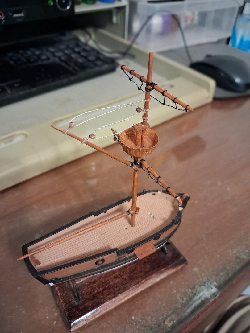
-
Baker reacted to a post in a topic:
HMS Grogblossom c. 1700 by Dan DSilva - 1:128 - hoy - solid hull
-
GrandpaPhil reacted to a post in a topic:
HMS Grogblossom c. 1700 by Dan DSilva - 1:128 - hoy - solid hull
-
JacquesCousteau reacted to a post in a topic:
HMS Grogblossom c. 1700 by Dan DSilva - 1:128 - hoy - solid hull
-
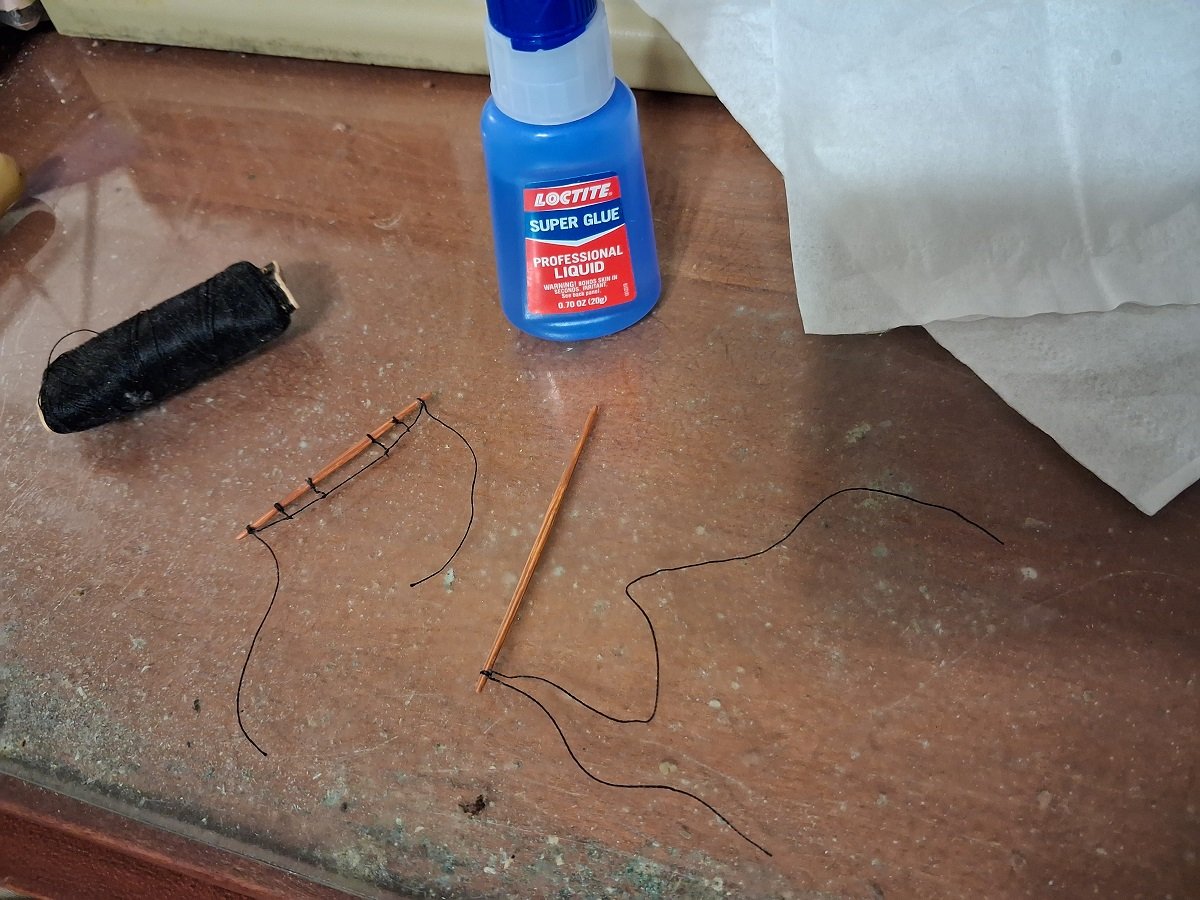
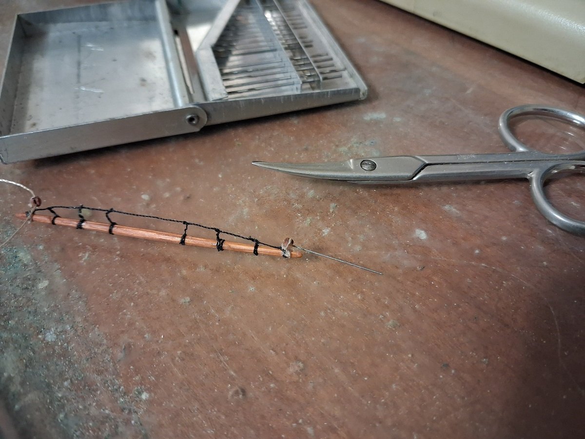
Okay! The Model Expo blocks are in and I'm finally officially starting to rig. Bad news: I have to use the smallest ones available and it's like trying to work with a poppyseed. Not a great start: It'd been so many months since I looked at proper pictures that I forgot that each yard is supposed to have two footropes. Also, I didn't strop the first block with a line through it, and I clogged it with glue. Great-Uncle Andy's tool chest saves my bacon yet again, as he had these incredibly tiny drill bits. I don't own a drill with a chuck small enough to use them, but I was able to use the bit between my fingertips Because of the small scale, I'm going with a simplified method for attaching the yards -- no blocks, just tied on with thread and glued.
-
GrandpaPhil reacted to a post in a topic:
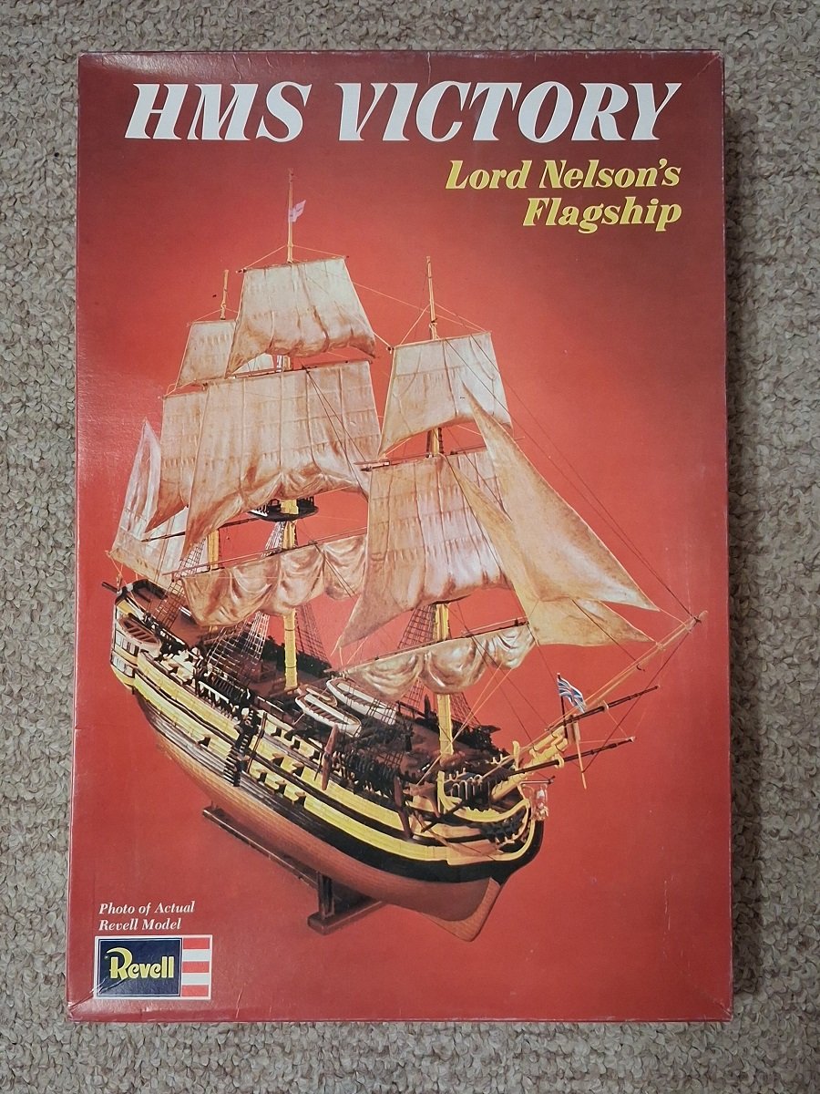
WTS: Revell HMS Victory, 1971 edition (updated)
-
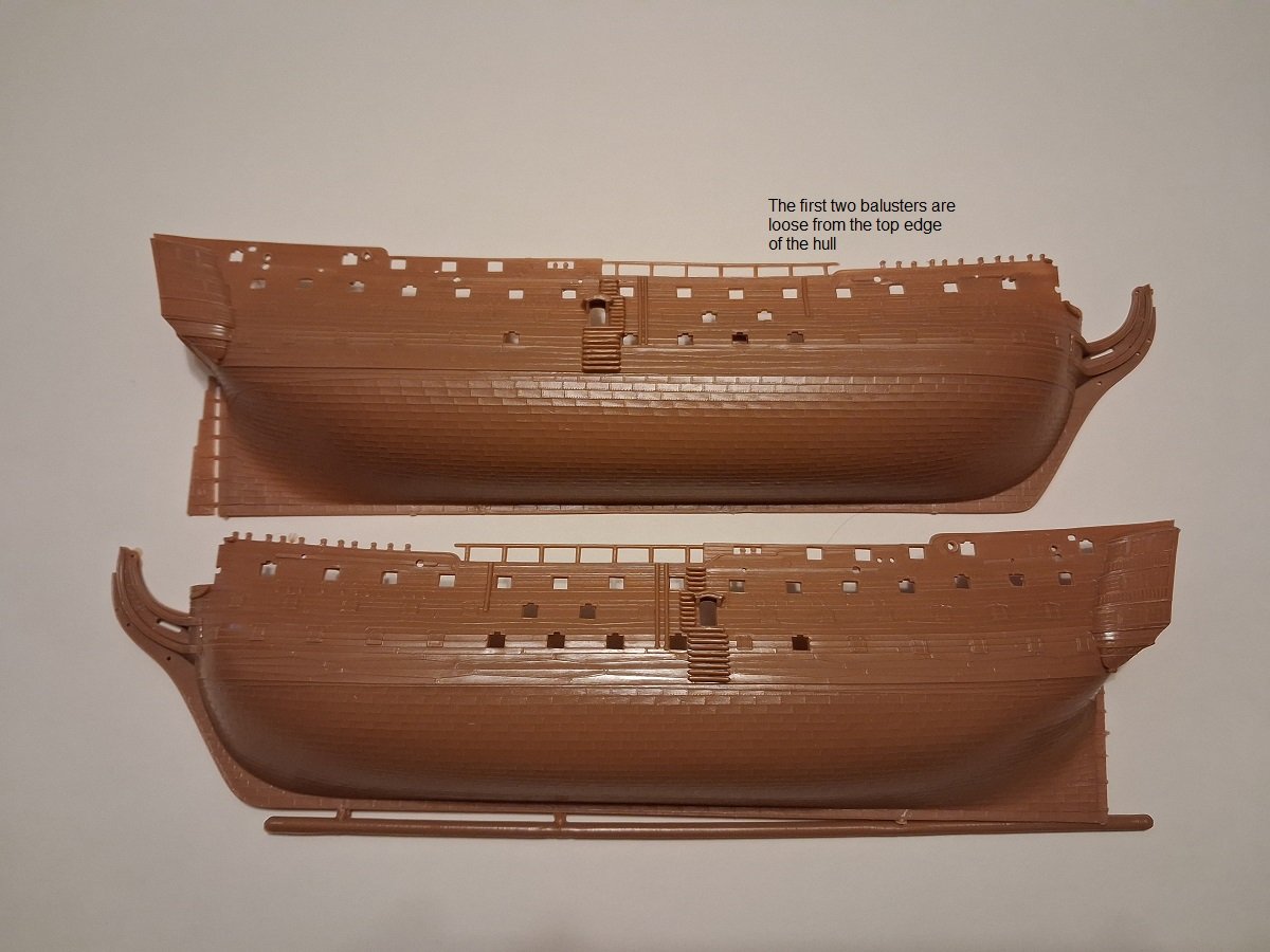
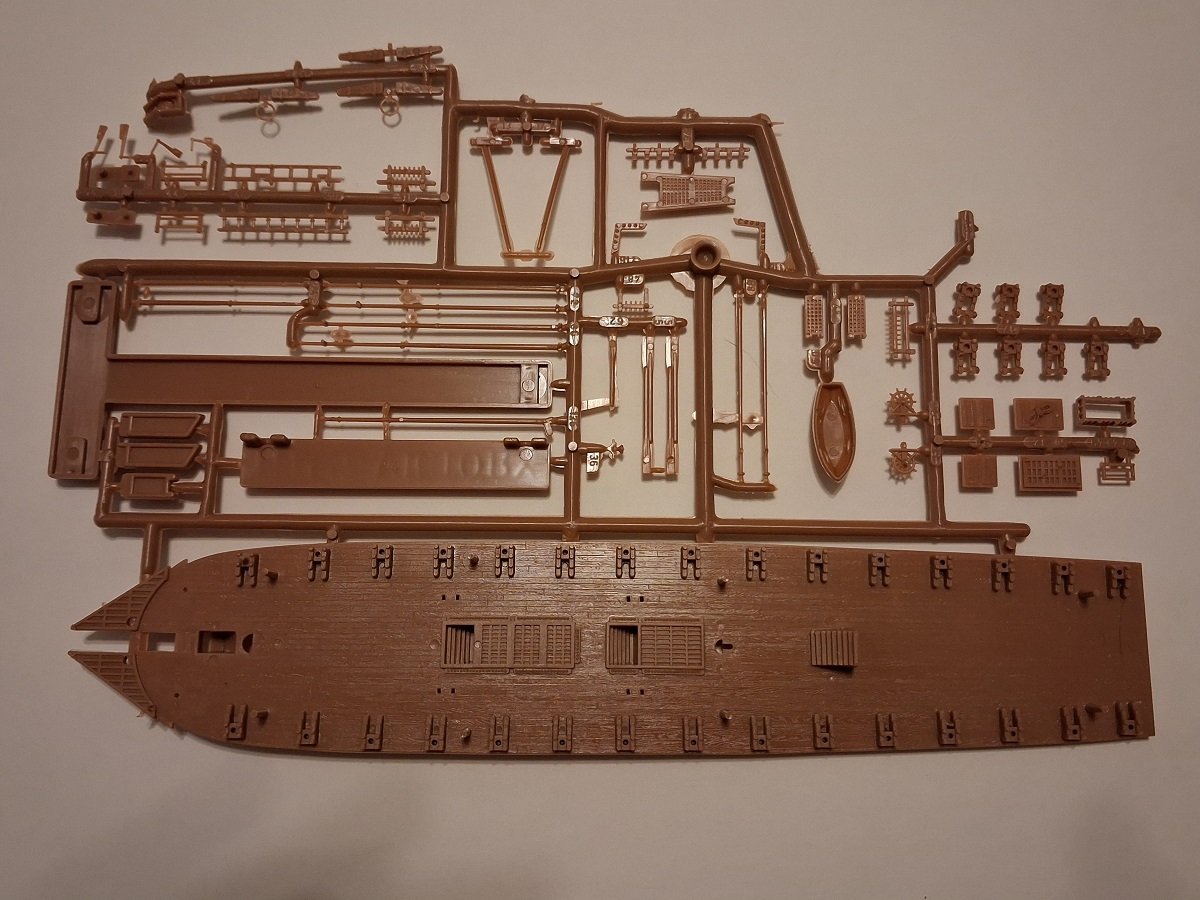
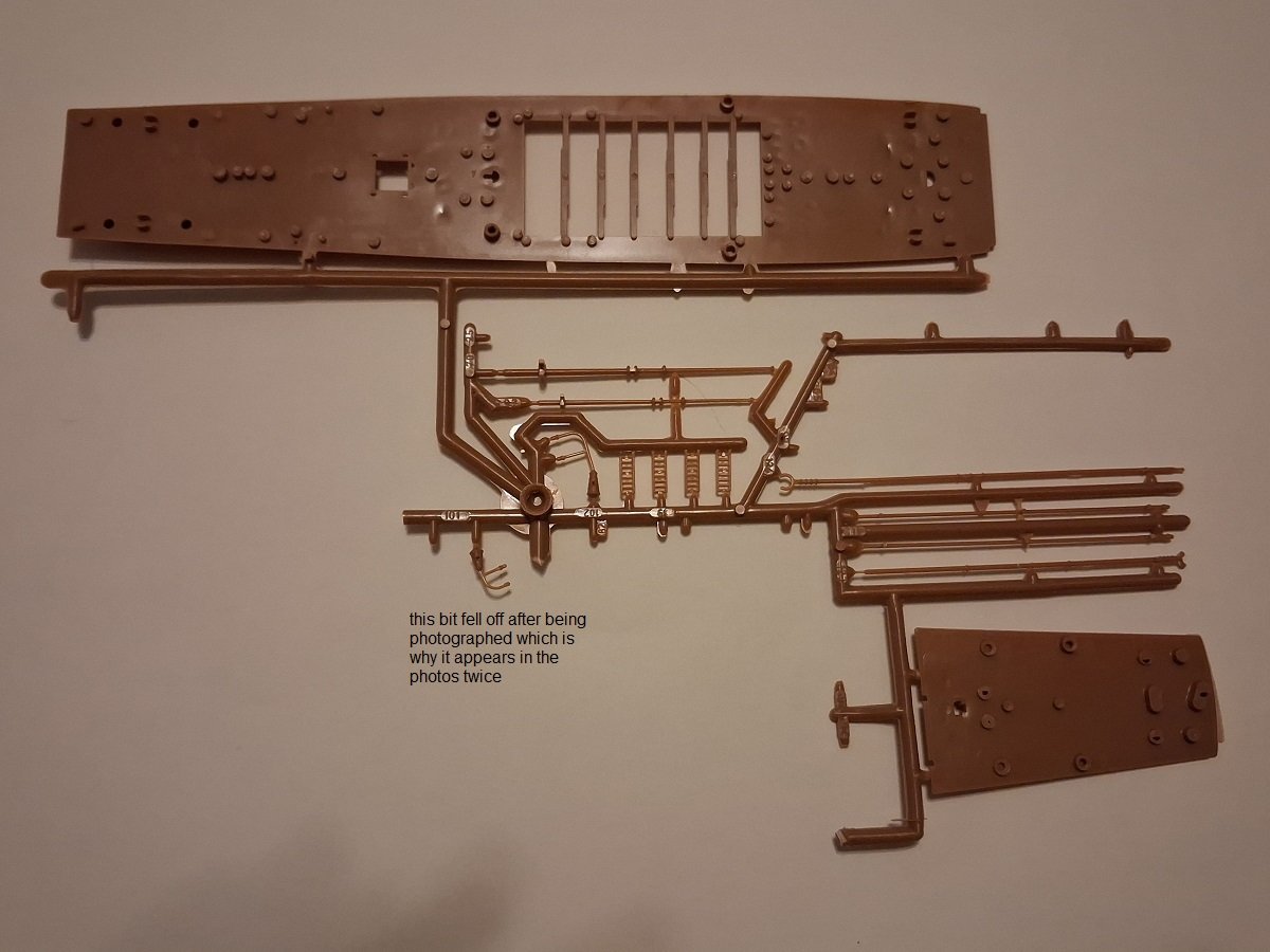
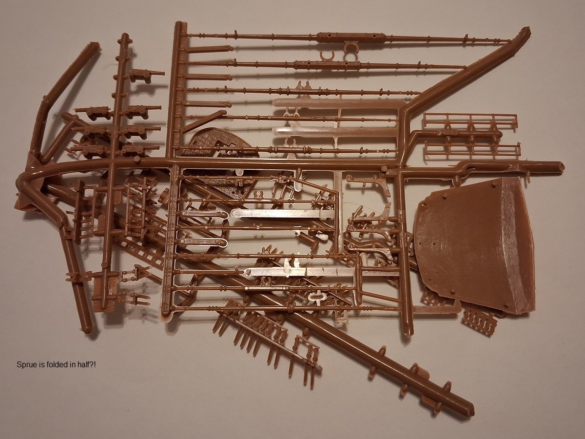
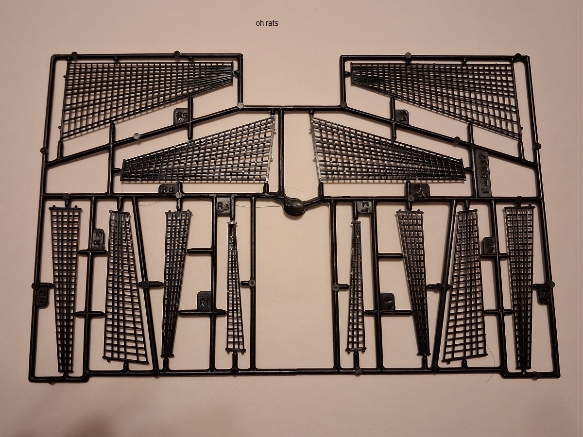
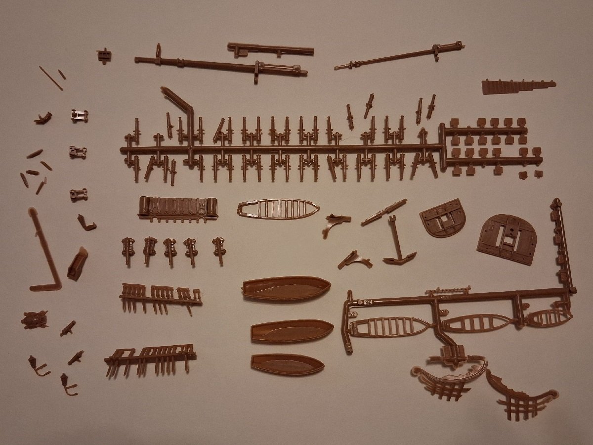
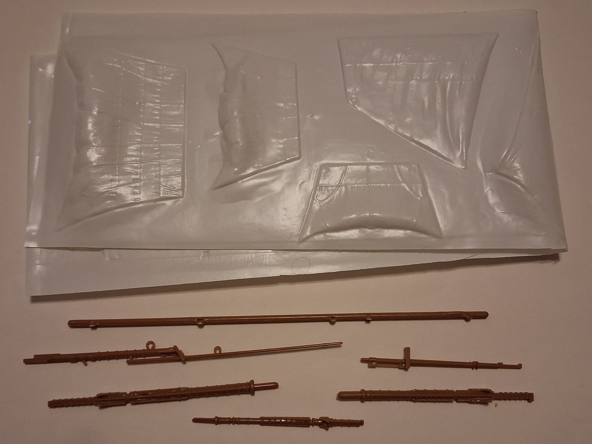
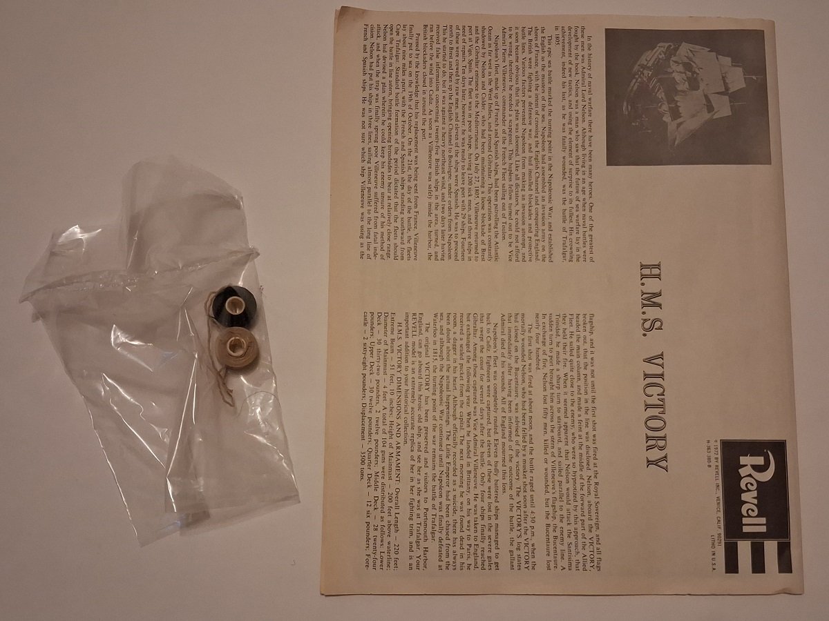
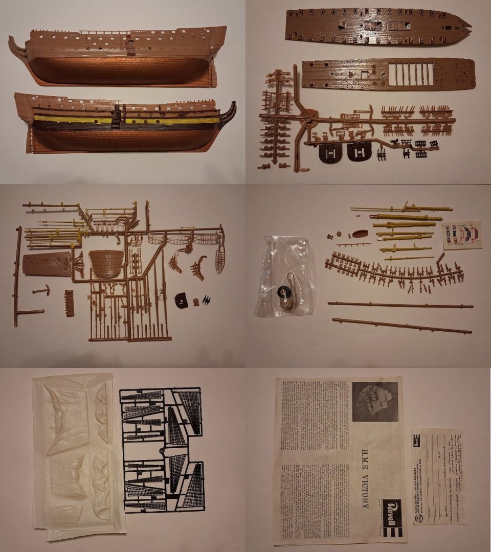
Bought this one with the intention of molding some parts for other models because it's from the period when it was mislabeled 1:146 and that's what the seller advertised it as. It's actually 1:225. It was sold as new, but lot of parts have fallen off the sprues. I've tried hard not to let anything go missing. I've seen build threads for this model and it can look great when finished. $30 shipped in the continental U.S. Shipping from Newtown, PA. PM me for PayPal if interested. Edit: If you like, I have another, partial kit for spare parts that I can send in the same box for no extra charge, just to reduce the chance of anything being missing or damaged.

-
- 1
-
-
Thanks. I'll look into getting a copy.
-
Thank you. Would you think the ten- and nine-oared boats would be a good general guide?
-
Tumblehome reacted to a post in a topic:
What did an early 18th-century pinnace look like?
-
Hello again. As mentioned earlier, I obtained an Airfix HMS Prince as the centerpiece for a War of the Spanish Succession collection. I gather from The Boats of Men-of-War that after 1702 Royal Navy first-rates were allotted a longboat, a pinnace and two yawls. I was wondering if anyone can point me to sources on what the pinnace would have looked like at this time. I know of the Model Shipways English pinnace, which is supposed to represent one from 1750-1760, and various plans from RMG which were drawn up in the 1790s, but obviously designs could have changed a lot from the 1700s to then, so I don't assume I can just copy one of them.
-
Keith Black reacted to a post in a topic:
When were these ropes added to the sides of ships' boats?
-
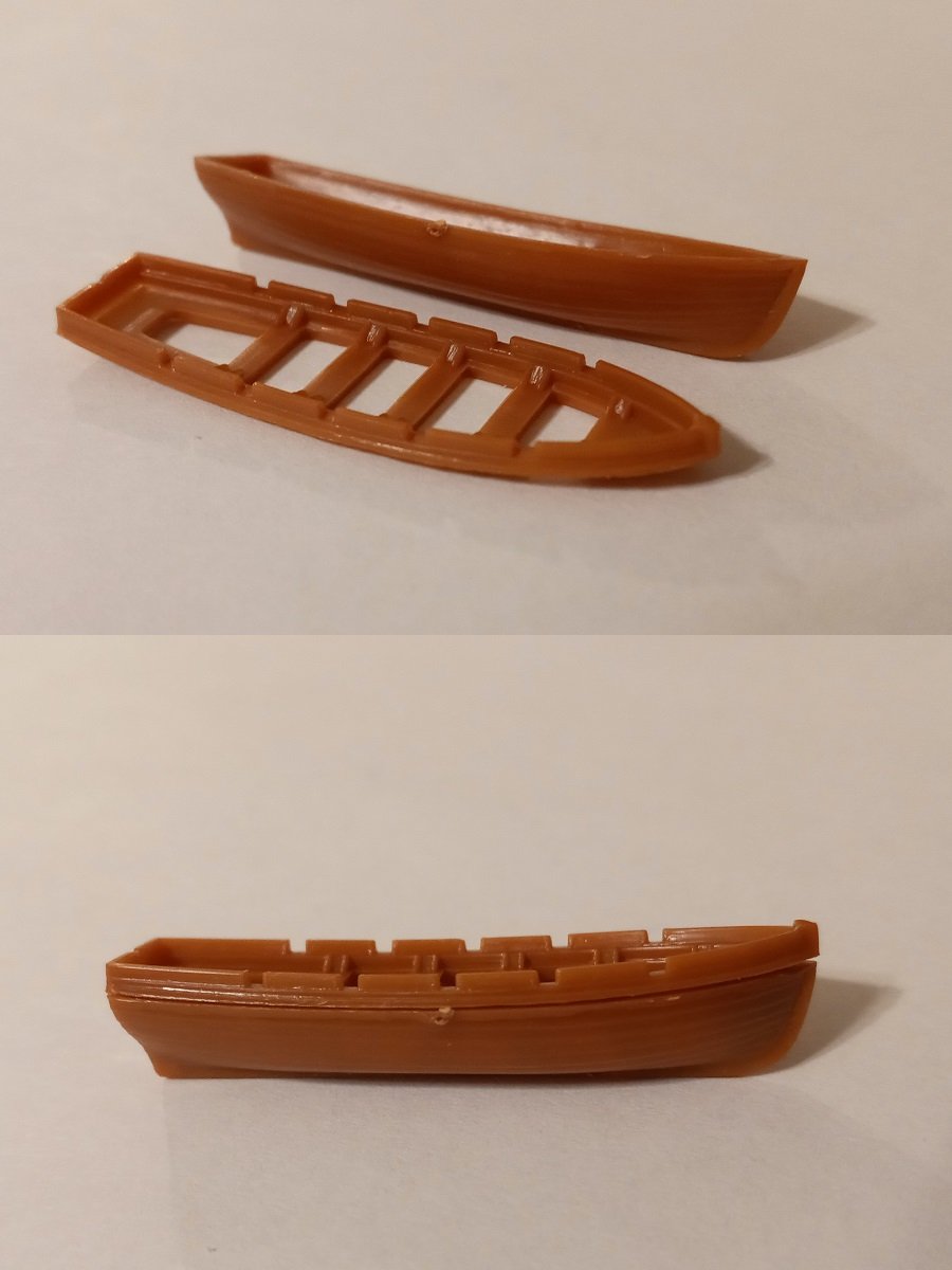
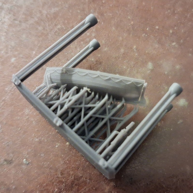
I got a dinghy from Micro Master. Unfortunately, with the lines being basically just raised ridges on the hull, I'm having a difficult time imagining how to remove them except by filing or sanding and an even harder time imagining doing that without damaging the hull or at least obliterating the strake detailing. With the level of skill I have at using an art knife, I really don't expect to be able to just scrape the lines off.
-
Keith Black reacted to a post in a topic:
When were these ropes added to the sides of ships' boats?
-
Keith Black reacted to a post in a topic:
When were these ropes added to the sides of ships' boats?
-
Thanks for that, I'll take a look ASAP.
-
Interesting. I'll give it a try like you say. Thanks for the advice.
-
Thanks. It's sounding like they should be avoided at least on ships' boats in the Age of Sail, which means most of the Micro Master boats would be unsuitable unless I was able to file or sand the ropes off.
-
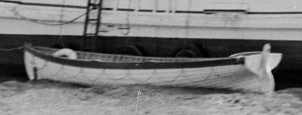
The ones that are attached so a row of half-circles hang below the rubbing strake. One of my books appears to call them lifelines, but everyone else seems to use that term differently. Picture yoinked from Ian Scales: I'm asking because I'm considering ordering some boats from Micro Master, most of which have these ropes. So I'd like to know whether they'd be anachronistic on boats from the 19th century or earlier.
-
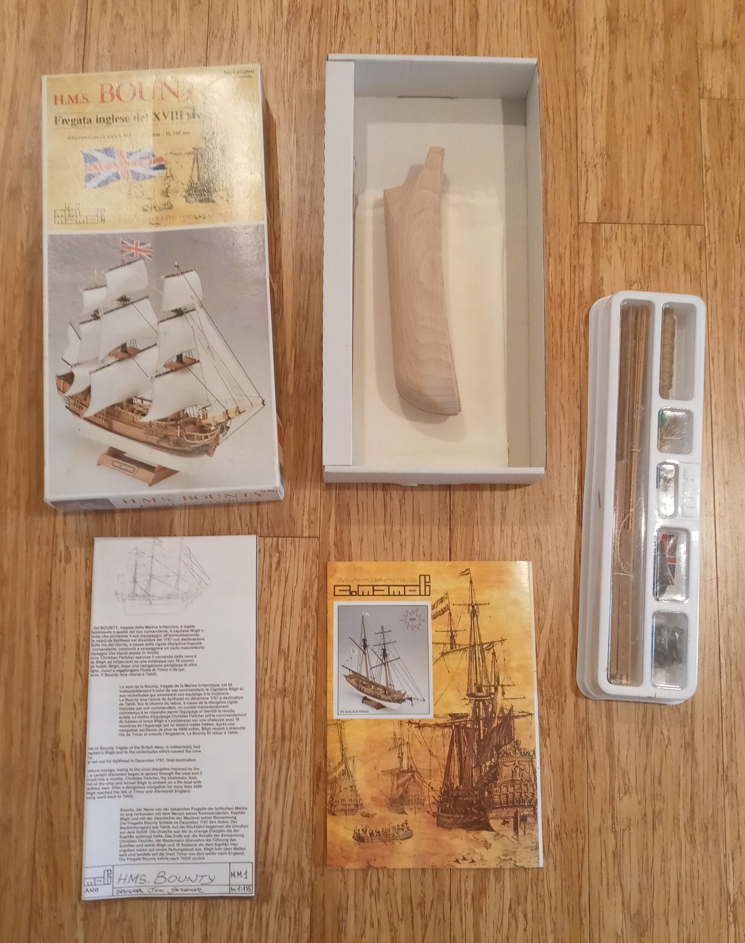
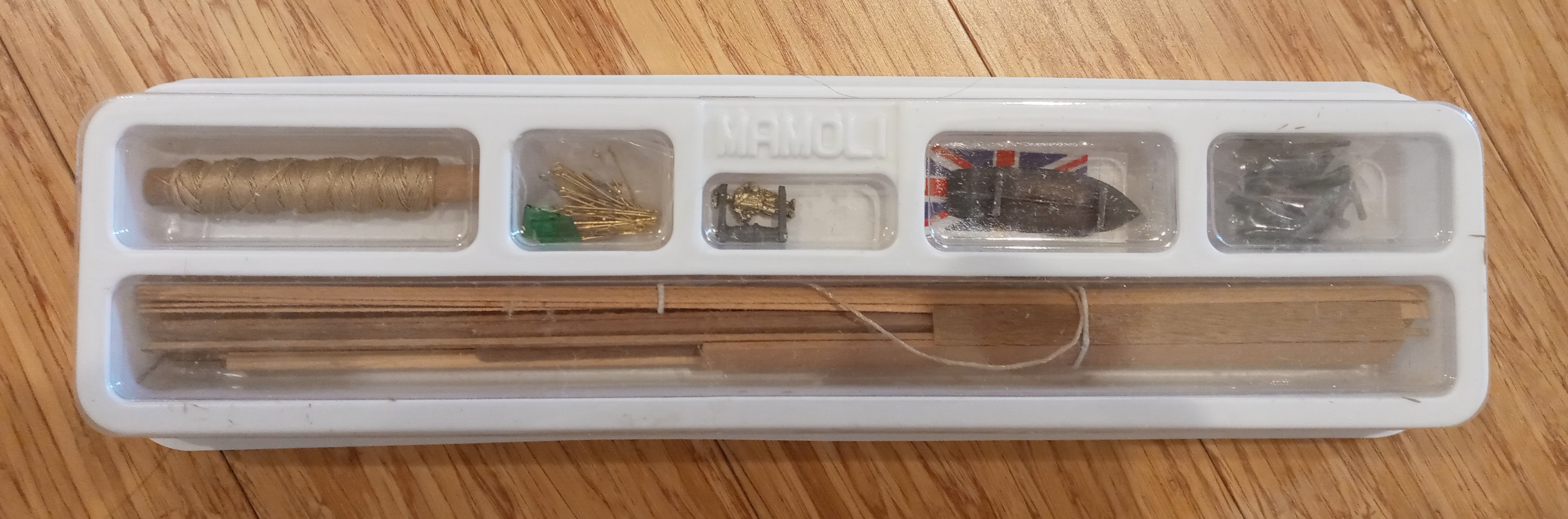
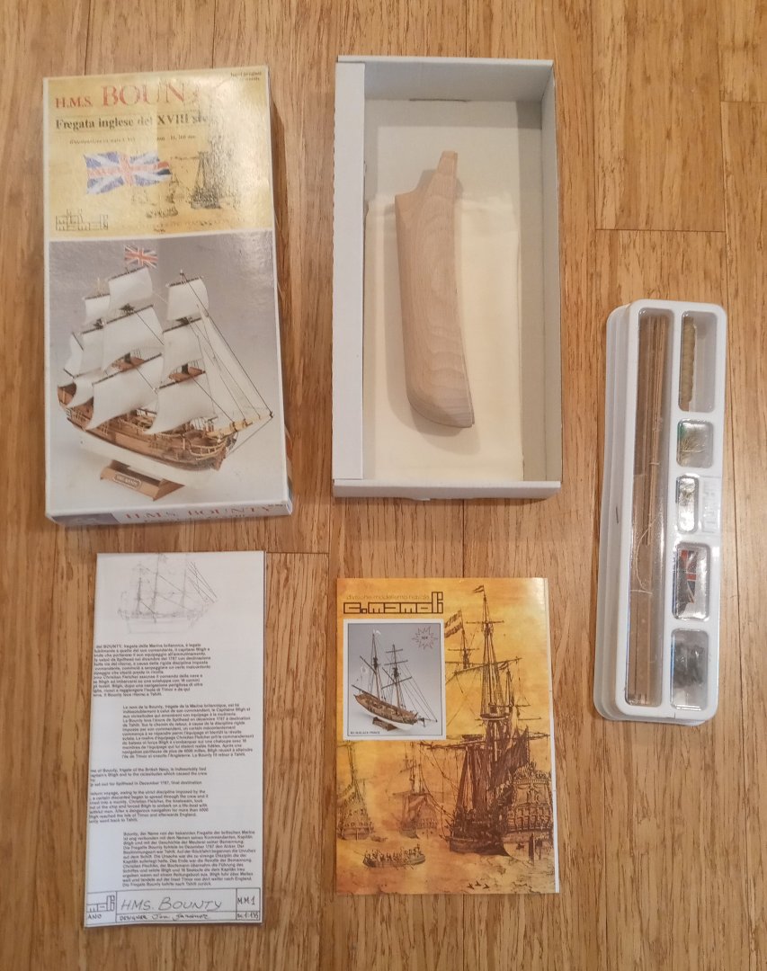
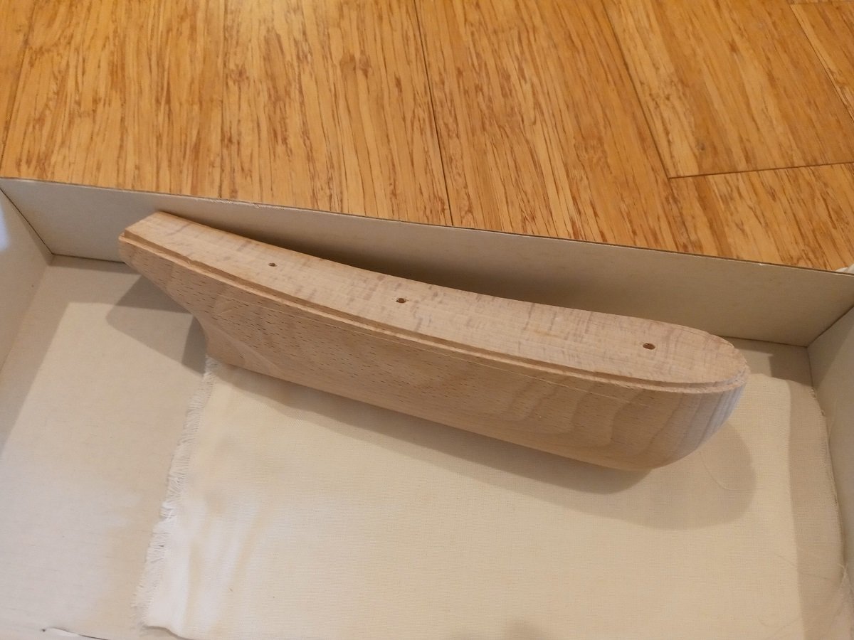
Bought for a home improvements project before I fully researched whether it would work or not; turns out the hull is too narrow. Box is opened but no work done. NGL, this isn't a great-looking kit; the bow, especially, could use reshaping. As is, it's just a step or two up from those models you see at souvenir shops at the shore. But I think someone with decent skills could make it look good. $35 shipped in the continental U.S. Shipping from Newtown, PA. PM me for PayPal if interested.

-
- 2
-
-
Thanks. I've been using May as my main source too; that's what led me to raise the question. May provides some evidence (page 17) that longboats were hoisted in at least some of the time from the days of Nathaniel Butler (he uses the spelling "Boteler") onward. I can't answer whether the Prince in real life was designed from the start to have room on deck to do this, but if Airfix based their version on an admiralty plan, I would guess it was designed to carry much smaller boats if any and tow its longboat.
-
Thank you. Sorry, I should've included a photo. By the way, the boats seem undersized to me, even at the official 1:180 scale (and I think the ship itself is closer to 1:150, which would make the larger boats at 37.5mm less than 20 feet long). But the capstan is also amidships on this model and a boat of more than 50mm or so would interfere with it being turned.

-
I recently got an Airfix HMS Prince (1670) for my War of the Spanish Succession fleet. It has three boats, whose gunwales have rectangular notches for oarlocks, and I'm wondering whether this is accurate for the late 17th to early 18th century, or I should try to modify them by filling in the notches and adding thole pins. If I'm reading The Boats of Men-at-War (page 65) correctly, it seems to say that this style of lock was introduced with cutters, and other types of boats were modified in the late 18th century to eventually have the same style. Can anyone corroborate or disprove these claims?