


bc_63
-
Posts
10 -
Joined
-
Last visited
Content Type
Profiles
Forums
Gallery
Events
Posts posted by bc_63
-
-
On 3/26/2023 at 9:19 AM, Baker said:
An example from a great modeler
Yes, thanks, Patrick. I've scoured his build repeatedly and already borrowed/stolen many, many ideas. 🙂
What I've decided to do is to square off the top of the mast at 7mm down to the top of the platform crosstrees; below that is a 4mm tall section that's 8mm square (to support the crosstrees), then go down another 35mm at 8mm round (cheeks). The taper will thus go from the bottom of the cheeks down to near the top of the weather deck. Right or wrong, that's today's project.
-
-
Thank you, Chuck, for taking the time to not only respond, but to go make a sample. Wow! Beyond gracious. And I truly appreciate your kind comments on the look of the rope I'm making.
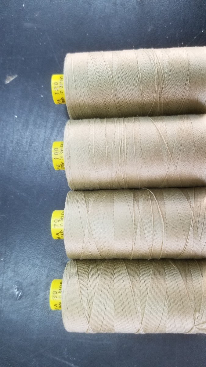
I'm not sure what's going on with the size, but it does make sense that perhaps my thread isn't quite right. Here's a picture of the 4 spools I have, and I'm pretty confident that I was using the 120.

Final question: Does the lay (left or right) make any difference on size?
Cheers,
Bryan
-
Thank you, Allan, I truly appreciate your response. I was able to sort out some, though unfortunately not all, of my questions from the RMG drawings. I think I'll just use my best judgement at this point, as this model is more about fun than trying to be 100% historically accurate...
Cheers!
Bryan
-
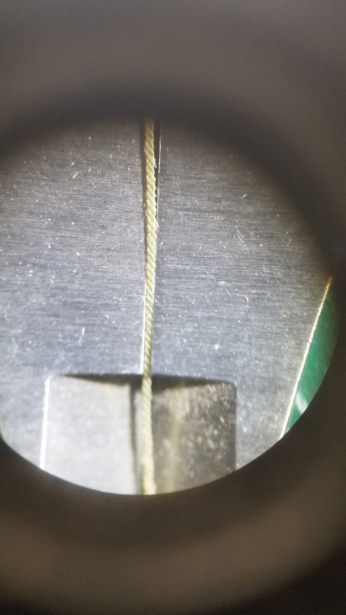
Thank you very much, Chuck. I have tried making the rope (3x Mara 120) as tight as I can but am unable to make it less than 0.015. Here's a shot of it fitting into calipers locked at that dimension:
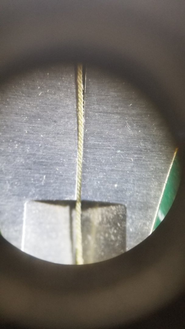
If I try to put more twists in the thread (before allowing it to start being rope), it starts bunching up on itself, which then ends up as little bumps in the rope. Obviously not acceptable.
At this point, I'll just use this rope for my model and I think it'll be fine. Net-net is that I'm really enjoying making my own rope and would not have even attempted this without your help!!
Cheers,
Bryan
-
Hello, first-time modeler here, and I'd like to start by thanking everyone for this great forum, from which I have picked up SO much already!!
I'm getting ready to start making the masts, etc., and am having trouble making sense of the instructions. I'm hoping that someone who has either built one of the Occre models, or someone who just generally knows this stuff, might be able to help me out here, please. Questions below this first set of drawings that I've made some annotations to:
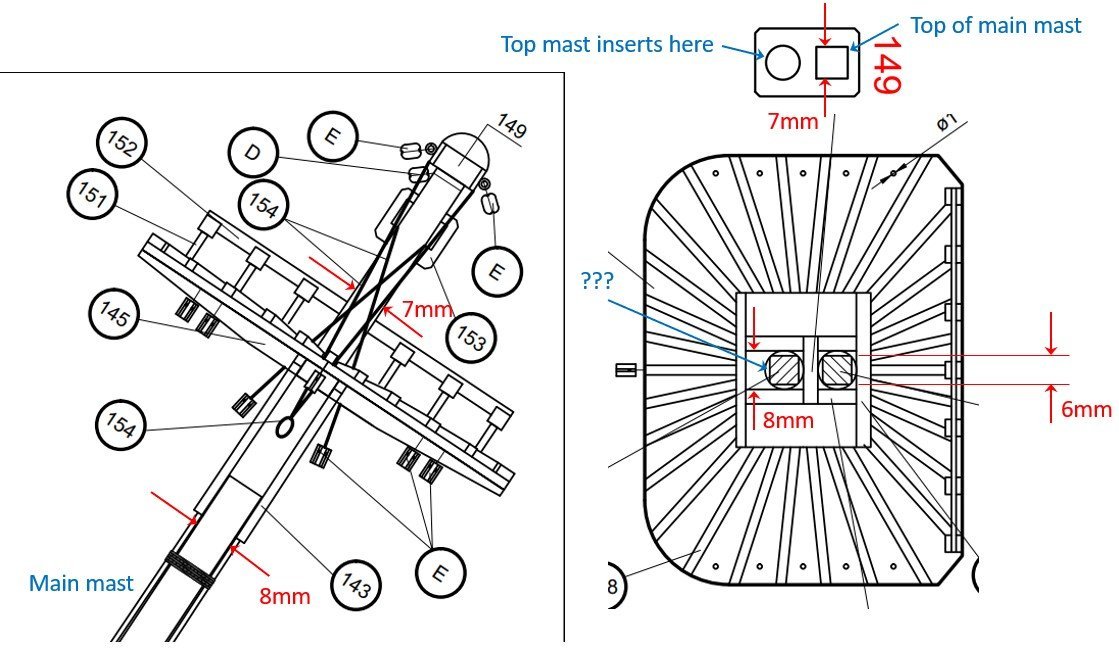
My primary question is this: Where should the main mast turn from round to square?
1) Under the cheeks? (would increase the contact patch between the mast and the cheeks)
2) Where it penetrates through the platform? (would provide rotational stability to the platform's supports)
3) Where it fits into the mast cap?
Some other questions:
a) Where should the mast diameter reduce from 8mm to 7mm? Just above the platform since the platform spacing is 8mm?
b) Why does the drawing show the top of the main mast squared off to 6mm when the mast cap's square hole is 7mm?
c) What does the square on the top mast indicate (the blue ??? callout)? The hole that it goes into in the mast cap (part 149) is round.
d) What serves as the "step" for the top mast and supports its base vertically?
I hope these questions make sense... Any and all advice or clarifying questions are welcome!
The model as it sits today...
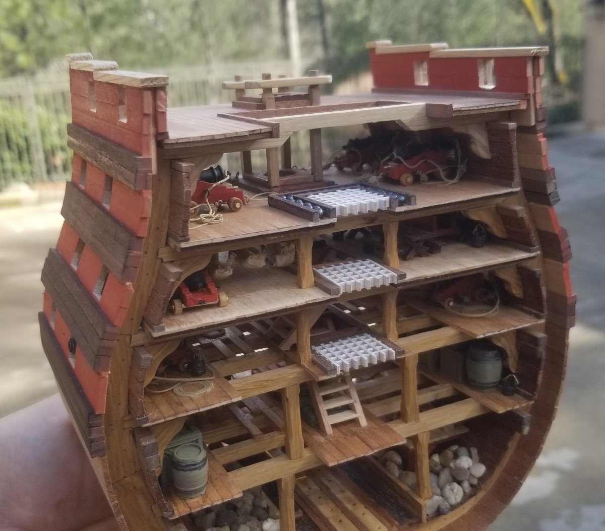
Cheers!
Bryan
-
Thank you, Sir! Very helpful. I like the idea of the 2nd set of pinrails and will steal/borrow that (along with so many of your other great ideas!) Things are just a bit too crowded in the area that the kit specifies for the side pinrails. And how they expect you to install 8 of their FAT pins in that location is far beyond my imagination.... 😉
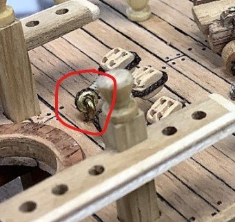
And if I may, one more question: Where did you find (or how did you make) these eyelet / ring assemblies? Very nice touch!!
-
Hi Chuck,
Please add my sincere note of thanks and appreciation to this thread. I'm a newbie model builder and rope-making hack, and trying to understand this process a bit better.
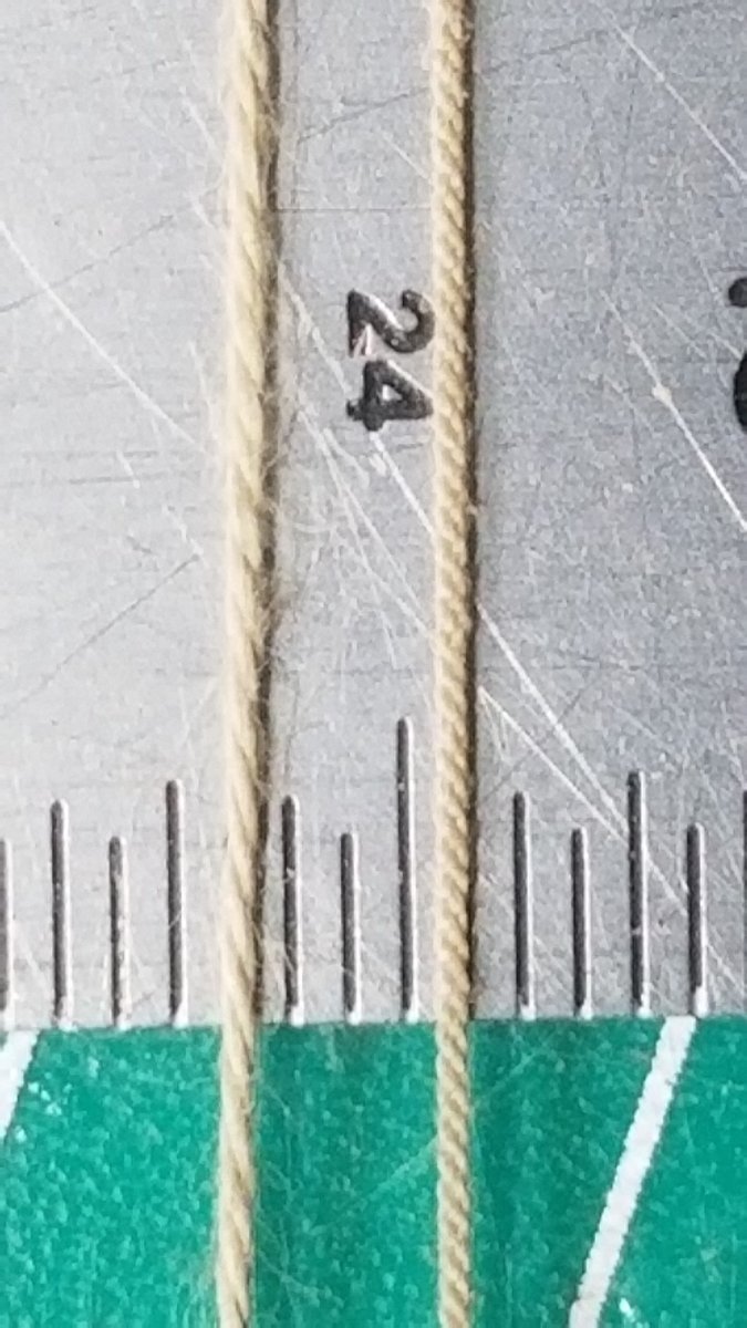
I've made this rope using 1x3 Mara 120. I measure it to be about 0.016", basically double the diameter of yours. (That's a 1/32" scale on the ruler.) Any tips on what I may be doing wrong?
Also in this picture is the thread that Occre supplies as 0.15mm, or 0.006". To my eye, they are about the same size, so clearly my confusion abounds.
Thank you!!

-
On 5/5/2020 at 6:24 PM, md1400cs said:
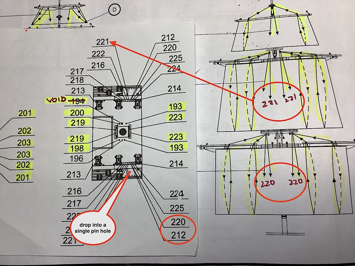
Now in the process of locating the ropes in the correct places – the instruction sheet only references only two pin locations per yard for 220 and 221 -- need four location.
And NOW looking even more carefully it appears as if locations numbers 212, and 220 drop into a same single hole. So need to find/invent four extra pin locations -- Need to figure out how to “fix” this grrrr.
Hello Michael,
I'm now to the point of sizing belay pin blocks and I want to thank you for the "heads up" regarding lines 220/221. Do you have any further thoughts on how this is supposed to be done? The plans seem to (loosely) indicate that the "inner" 220s head down toward the base of the mast while the "outer" 220s are secured on the side pin blocks. Of course, no attachment point is listed for the "inner" 220s. Same thing for the 221s. Did you end up running all 4 of each set to the outer blocks? Thank you!

Order of attack for rigging a model (section)
in Masting, rigging and sails
Posted · Edited by bc_63
Hello, first-time modeler here. I've completed the hull of the Occre Santisima Trinidad cross section, plus completed the spars and all attached blocks, but am now a bit intimidated by the rigging itself. Specifically, I'm wondering what you folks here generally do in terms of the order of attack of the various jobs.
Occre's plans seem to suggest:
1) Main mast installed, all three sections
2) Standing rigging complete
3) Yards installed
4) Sails lashed to yards
5) Running rigging installed
I've also gleaned a great deal of information and learning from Michael (md1400cs) and his build of this same model. His order:
1) Build the mast up from 3 sections
2) Mid and upper shrouds installed onto mast assembly; install upper ratlines
3) Sails lashed to the yards
4) Prelim install of much of the running rigging
5) Yards installed to the mast assembly
6) Complete running rigging on mast assembly (all dangling loose for now)
7) Finally, insert mast assembly into hull
8 ) Tie off running rigging to pin rails, etc.
9) Last step, install main mast shrouds and ratlines
So there are a couple of approaches and I imagine there are more ways to do this. I've searched through this section of the forum, going back several years, so I'm hoping that this hasn't been asked and answered a hundred times already -- apologies if it has. I appreciate everyone's input on this.
Thank you!
Bryan