


OkesaBuilder
-
Posts
31 -
Joined
-
Last visited
Recent Profile Visitors
233 profile views


-
 Mirabell61 reacted to a post in a topic:
Okesa 1918 by OkesaBuilder - Scale 1:96 - Ferris Type WWI Wooden Steamer built in Portland Maine
Mirabell61 reacted to a post in a topic:
Okesa 1918 by OkesaBuilder - Scale 1:96 - Ferris Type WWI Wooden Steamer built in Portland Maine
-
Mirabell61 reacted to a post in a topic:
Okesa 1918 by OkesaBuilder - Scale 1:96 - Ferris Type WWI Wooden Steamer built in Portland Maine
-
Mirabell61 reacted to a post in a topic:
Okesa 1918 by OkesaBuilder - Scale 1:96 - Ferris Type WWI Wooden Steamer built in Portland Maine
-
Mirabell61 reacted to a post in a topic:
Okesa 1918 by OkesaBuilder - Scale 1:96 - Ferris Type WWI Wooden Steamer built in Portland Maine
-
FriedClams reacted to a post in a topic:
Okesa 1918 by OkesaBuilder - Scale 1:96 - Ferris Type WWI Wooden Steamer built in Portland Maine
-
FriedClams reacted to a post in a topic:
Okesa 1918 by OkesaBuilder - Scale 1:96 - Ferris Type WWI Wooden Steamer built in Portland Maine
-
FriedClams reacted to a post in a topic:
Okesa 1918 by OkesaBuilder - Scale 1:96 - Ferris Type WWI Wooden Steamer built in Portland Maine
-
FriedClams reacted to a post in a topic:
Okesa 1918 by OkesaBuilder - Scale 1:96 - Ferris Type WWI Wooden Steamer built in Portland Maine
-
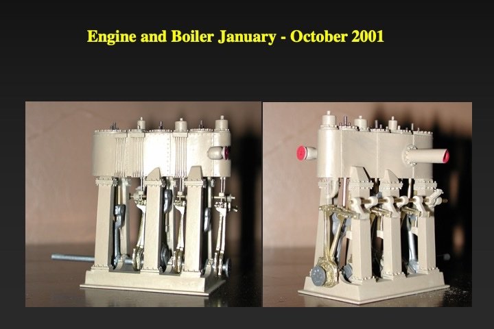
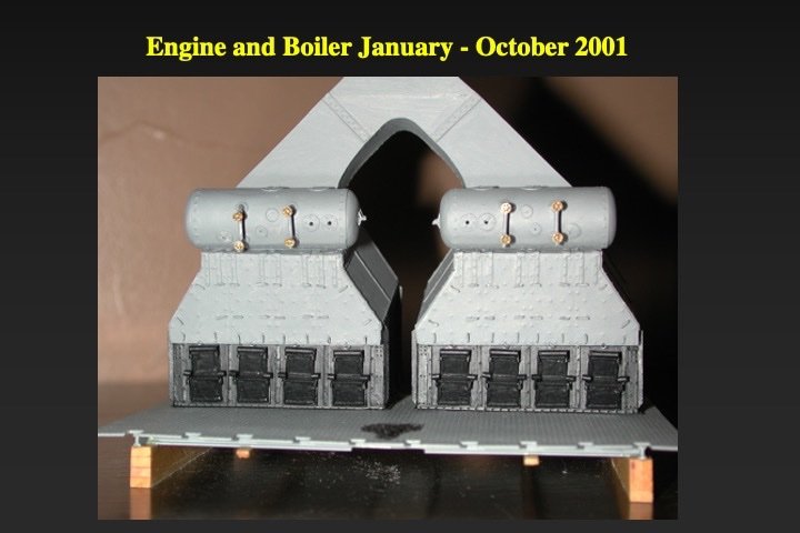
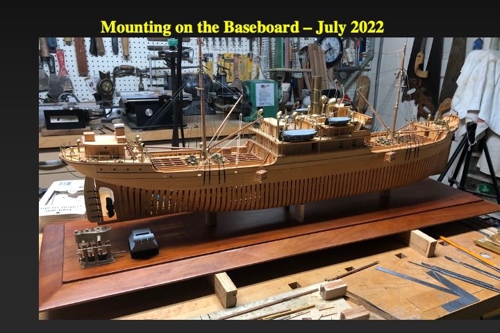
Thank you all for yourwonderful comments. A copy of the boiler and engine are mounted on the baseboard.
-
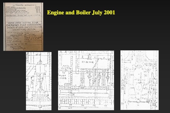
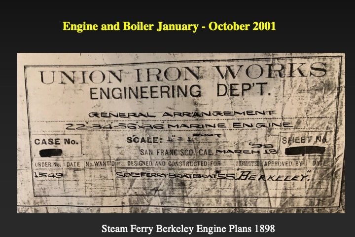
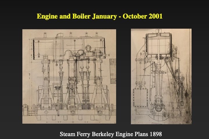
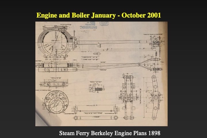
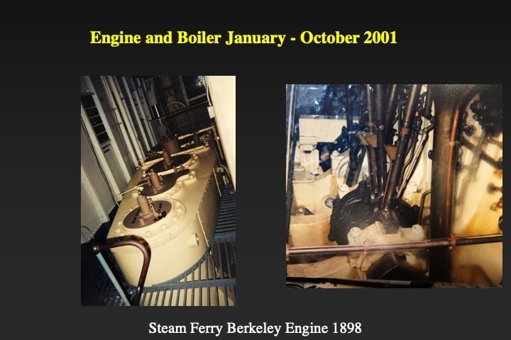
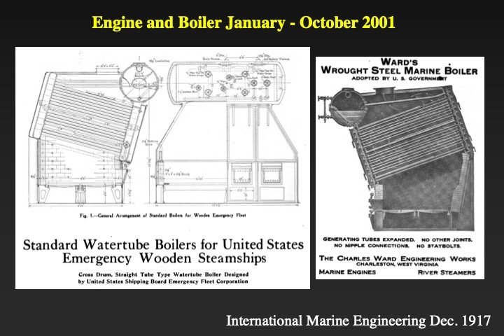
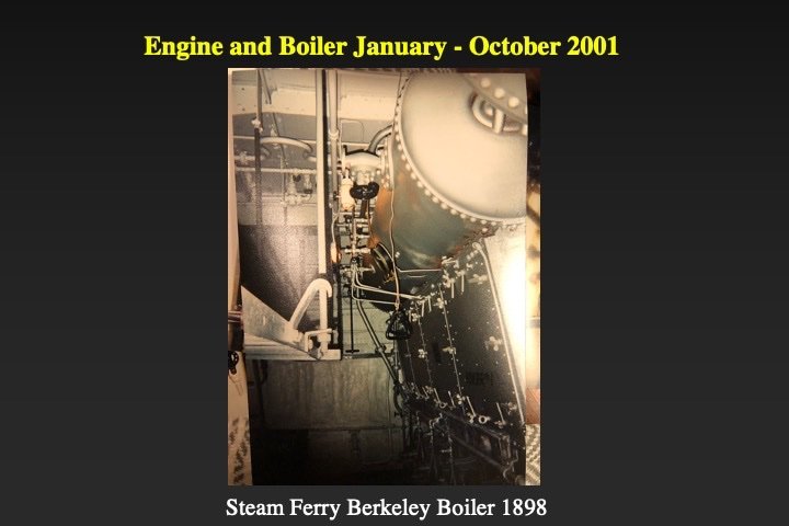
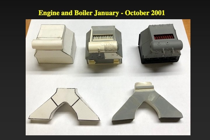
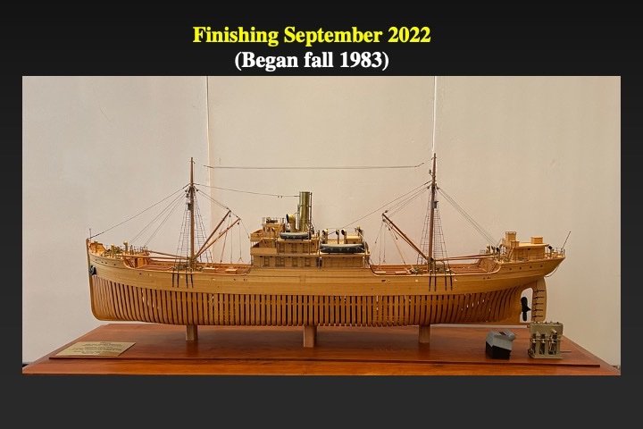
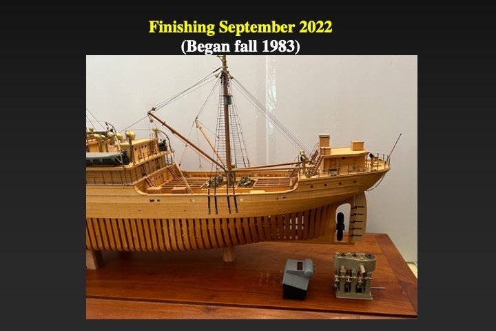
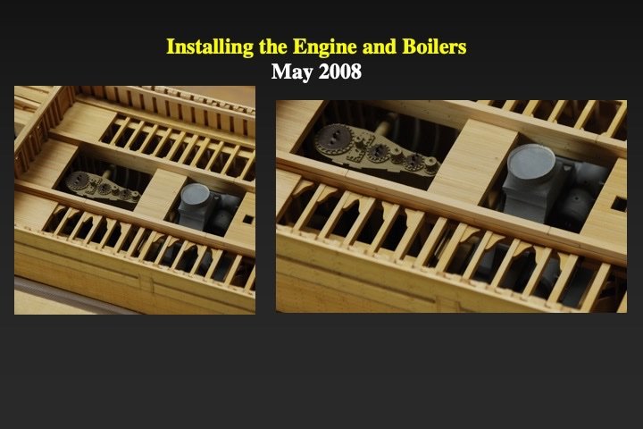
Postscript: Back to the engine and boilers. These were made in 2001 and then stored in a safe place until needed. There are extensive!!! plans of the 1898 triple-expansion steam engine that was installed on the ferry Berkeley at the California Marine Museum (San Diego branch). The Ferris-type wooden steamship engines were nearly identical. I also had (rough) plans of the engine from the Emergency Fleet Corporation documents. I also took many pictures of the Berkeley engine (and boilers). The engine was modeled from wood, plastic, and brass. Some of the parts were carved from boxwood and then cast in plastic. Nearly all the important parts were modeled; including the drive shaft, the pistons, the eccentrics, and the reversing gear. I built two engines: The poor one is inside the model and the better one is mounted on the baseboard. The boilers were built of plastic using plans from the 1918 journal of International Marine Engineering. I made paper models first, then plastoc mock-ups and then finally made three boilers. The "worst" two are inside the model and the best one is mounted on the baseboard. Now truly Fin'
- 40 replies
-
- 12
-

-
-
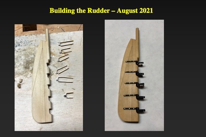
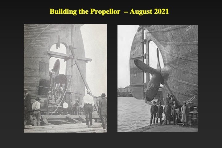
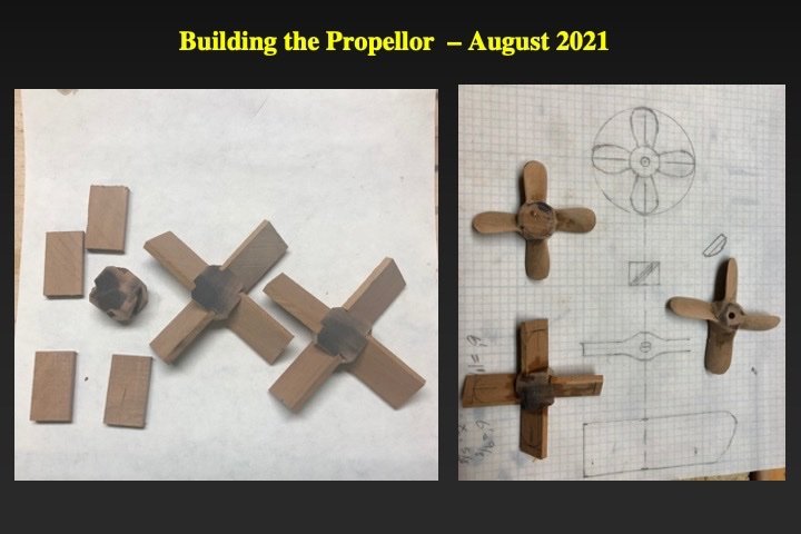
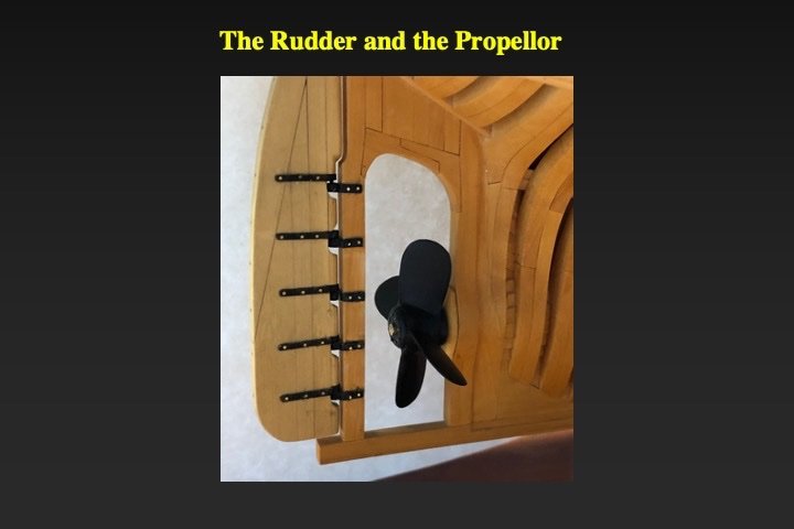
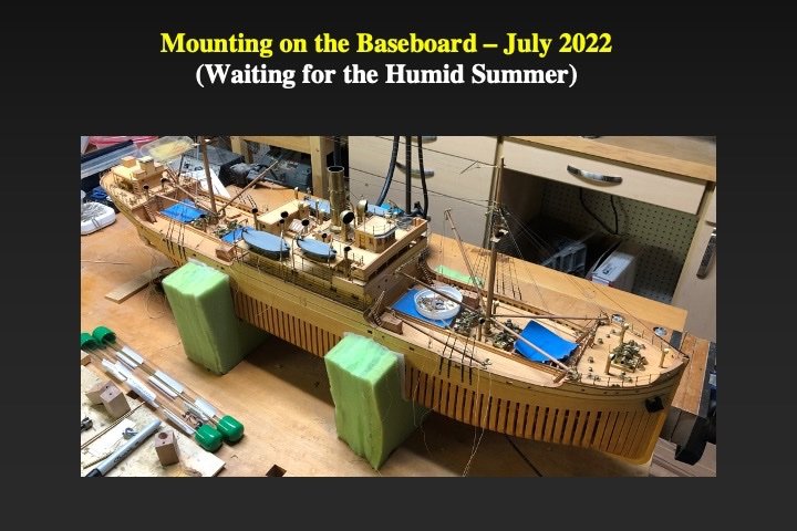
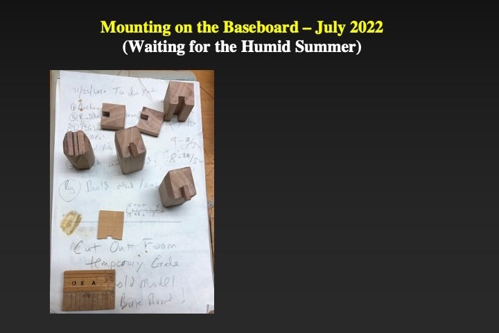
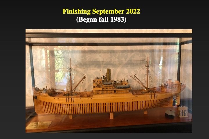
I was onto the final stages. The rudder was modeled next. There was a dedicated plan of the rudder in contemporary Emergency Fleet Corporation plans from 1918. The rudder was built up as per those plans. The propellor was modeled using a contemporary picture of the Ferris-type wooden steamship as well as other photos. The propellor was built-up from an applewood blank, shaped with the Foredom and hand-finished. Note that I made three propellors - to practice my carving technique. As mentioned above I knew that I wanted to show the operations of cargo loading. For that I needed crates. I found online some 1917-1918 articles on crate building. I built the crates using that information. Finally the model was ready to be mounted on its cherry baseboard. To make the model completely secure I used four applewood pedestals - two for the keel approximately in-line with the masts and one each 2 inches port and starboard of the keel amidships. Because of the low- and high-humidity in the winter and summer, respectively, where I live, I waited until the summer to mount the model (when the model, baseboard and case were most expanded). While the model is secure, there is also sufficient space for expansion and contraction of the model, baseboard and case with the weather. I purchased a cherry case kit from Bluejacket Shipcrafters. The case was extensively modified using cherry lumber I had on hand. Each off the frame parts were separately painted with multiple coats of black paint (and wet-sanded between coats with 400-600 emery paper). The final coat was clear satin lacquer and then case was assembled. Museum quality/low glare acrylic was used for the panes. Fin'
- 40 replies
-
- 11
-
-
-
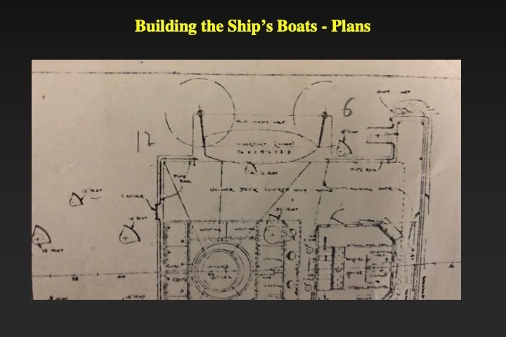
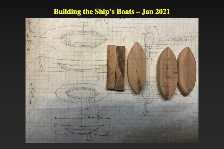
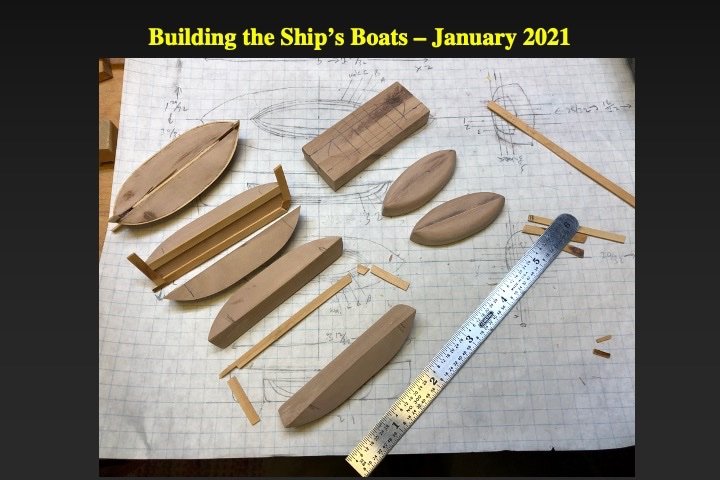
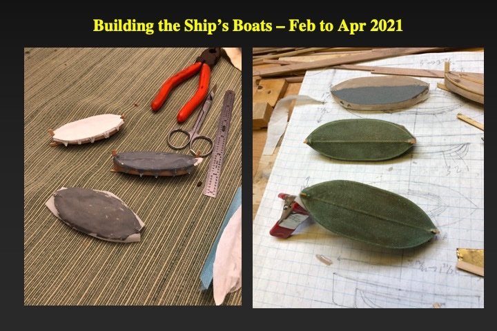
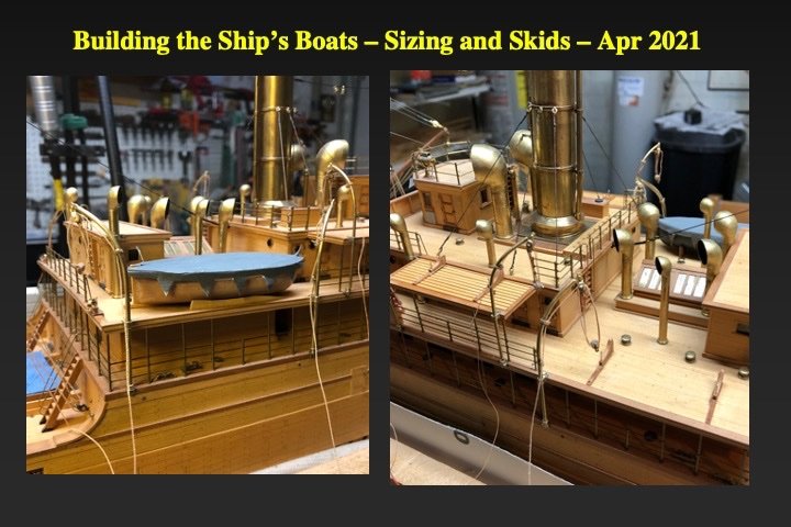
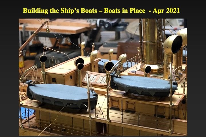
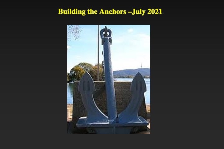
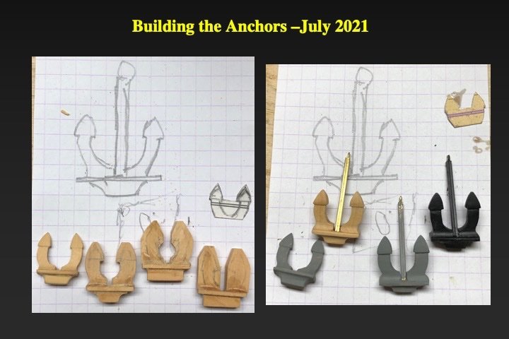
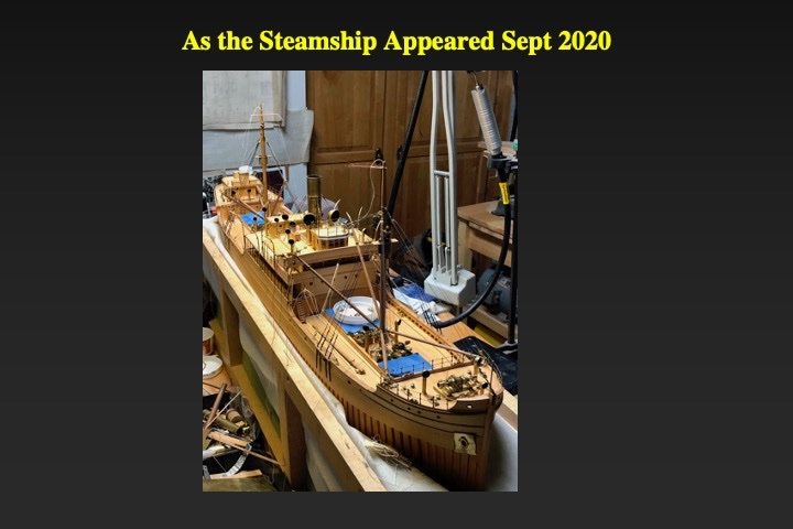
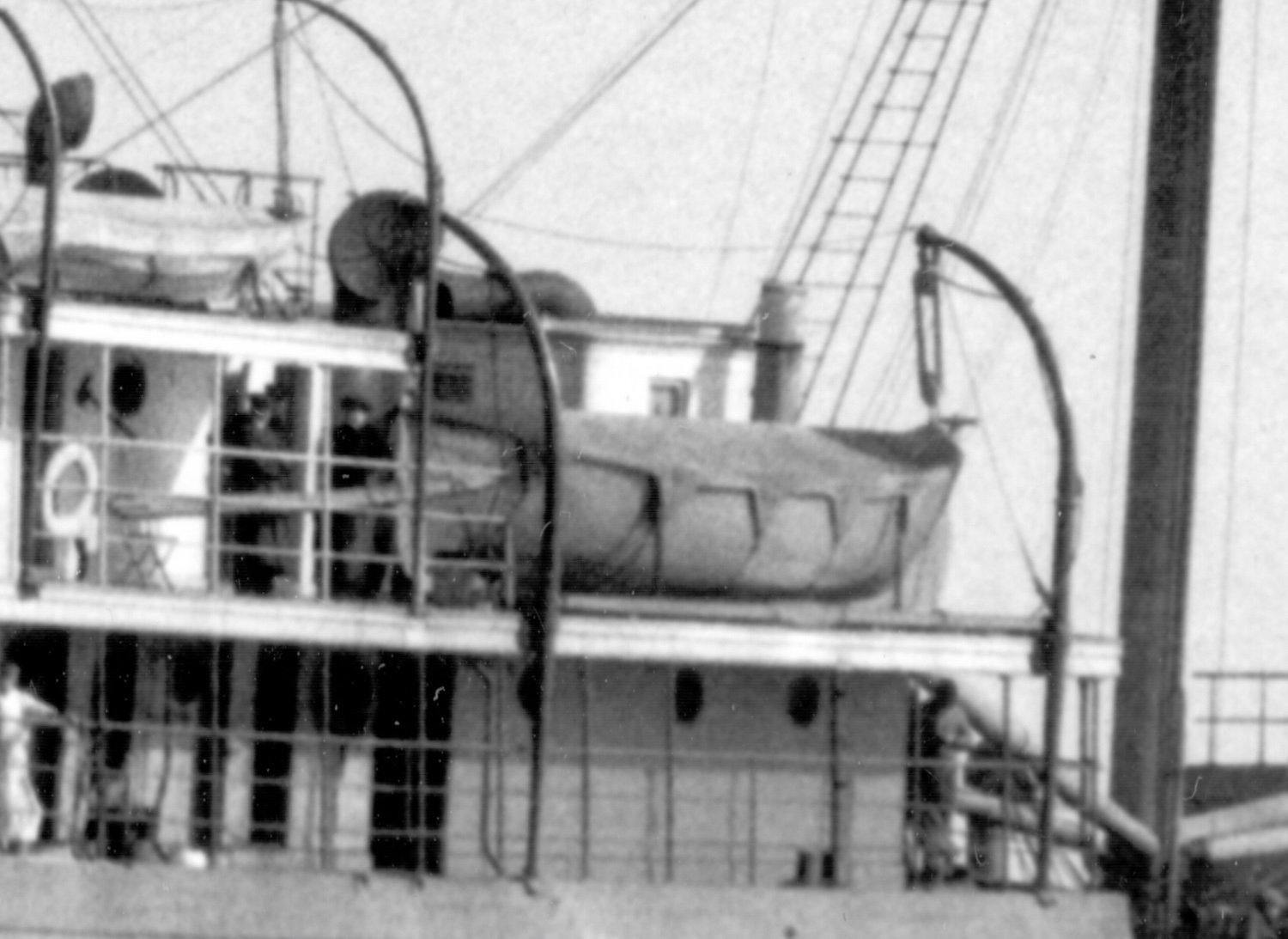
Another modeling hero of mine was the late Dana McCalip; a prior NRG Director. In honor of Dana I used his method for making the ships boats; One that he taught me many years ago. Two matching blocks of applewood were temporarily glued together and carved to the appropriate lines. The halves were separated and the stem, keel and stern post were inserted. The challenge for the ship's boats was modeling the tarpaulin coverings (see picture from the ship Okesa). I tried paper and plastic screen (see left side of picture 5) - neither gave the look I wanted. Finally I tried finely woven cotton batiste cloth. I wrapped the cloth around a saran covered"dummy" model. I "painted" the cloth with epoxy. Once the epoxy cured I gently removed the model tarpaulin from the "dummy," trimmed it, painted it maritime gray and then attached it to the ships boat. Looked great (See right side of picture 5). The contemporary Emergency Fleet Corporation plans from 1918 explicitly described how the ships boats were installed - including the components of the skids. I modeled the skids as per those plans. The captain's launch was only temporarily installed. Someday, I hope to build an scale replica of the launch; showing its internal construction, fittings and gear. The steamship's anchors were constructed from wood and brass. I made four anchors and picked the best two to go the model.

- 40 replies
-
- 13
-
-
-
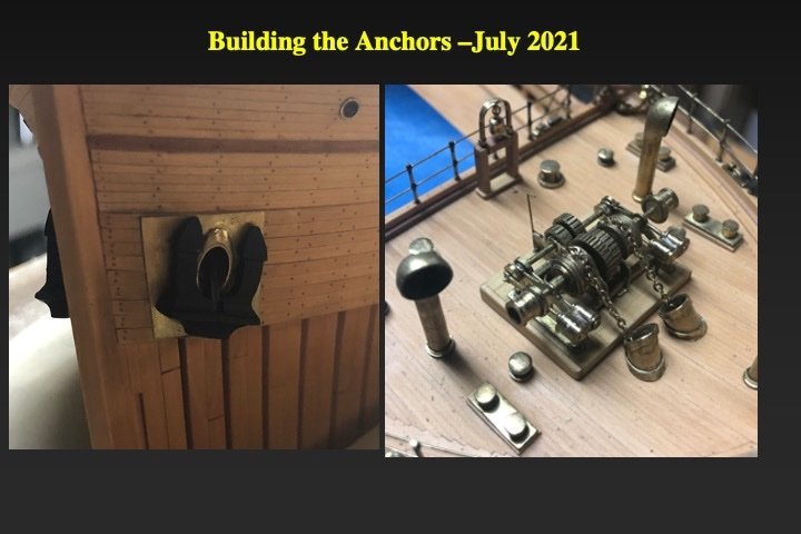
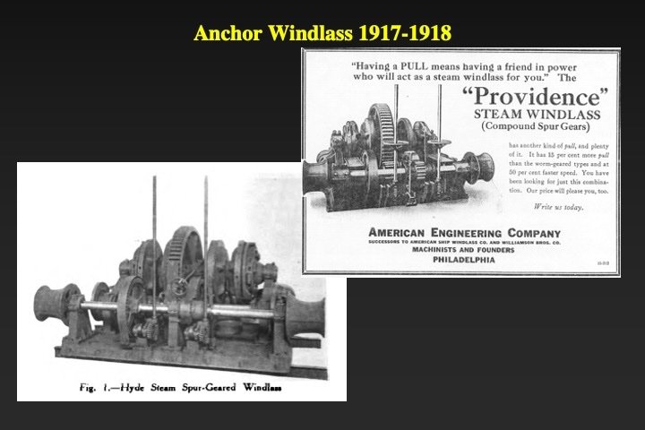
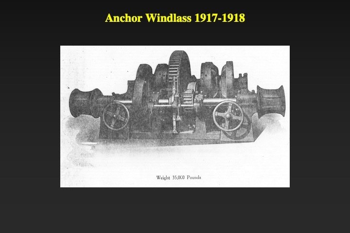
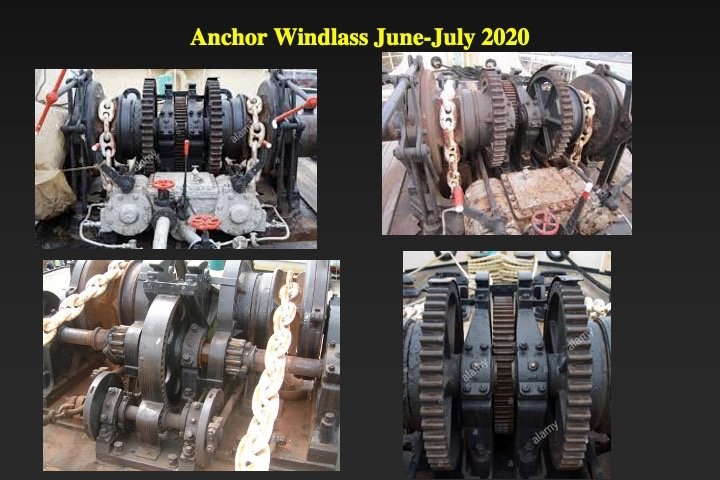
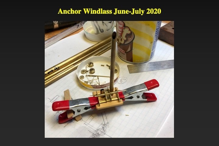
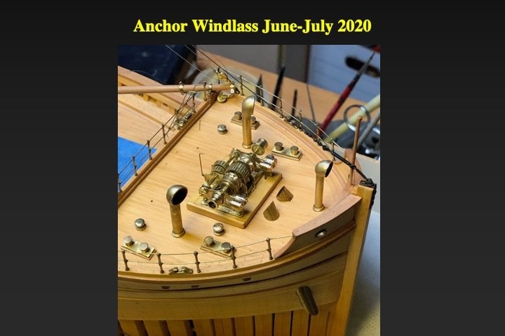
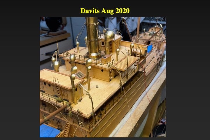
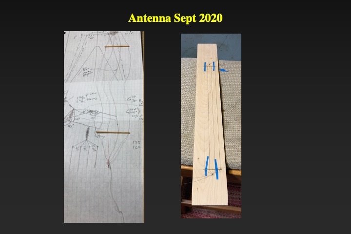
The anchor windlass presented challenges. I had a picture of the bow of Okesa, showing much of the windlass in partial profile. I found other contemporary pictures of similar period windlasses in the 1918 volume of the International Marine Engineering journal and from pictures from ships of the period. However, the arrangement of the windlass components (and their relationship to each other) in those pictures did not match the actual windlass on the Okesa. So I drafted new plans based on the Okesa windlass - using parts that I could discern from the other contemporary pictures. From my research I knew that the steam components of winches and windlasses were very similar. So I used many winch parts in the windlass. The contemporary Emergency Fleet Corporation plans from 1918 explicitly described the components of the davits, their layout and their rigging. I modeled the davits from brass components, wooden blocks and scale manila (linen) rigging. The Ferris steamships carried a wireless (radio) room (deckhouse). An antenna was rigged between the two masts that facilitated wireless communication (and direction-finding). I built the antenna with beading wire (with the plastic burned off), brass spreaders, wooden blocks and scale manila (linen) rigging.
.thumb.jpg.87156fc3c1c7301a104d7a6ec2019c93.jpg)
- 40 replies
-
- 11
-
-
-
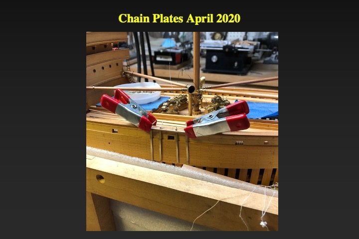
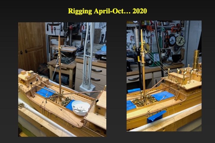
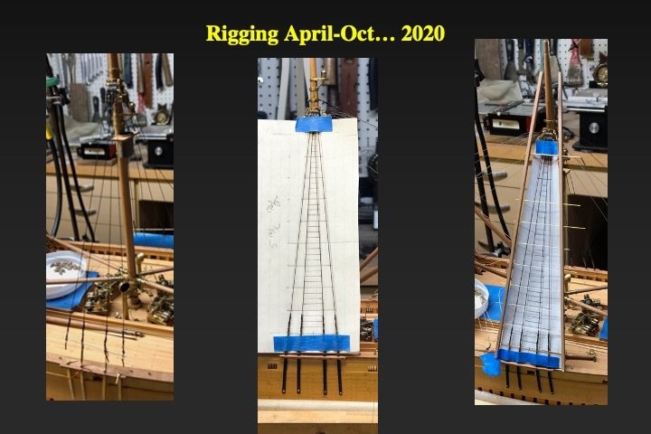
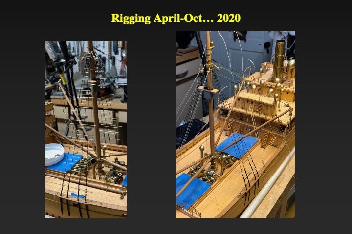
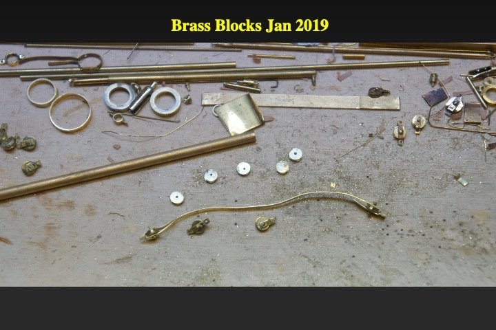
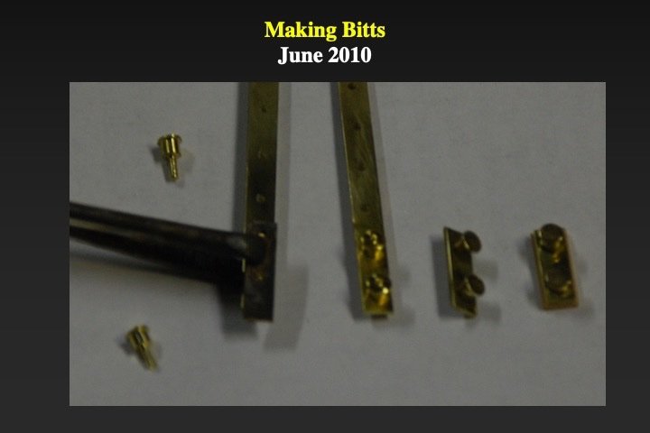
The COVID came...... And suddenly I had more time at home and had more time to complete the rigging of the steamship. When the contemporary EFC plans arrived from the National Archives (in the 1980s), I was surprised to see that they explicitly documented the different ways the booms were rigged for various stages of cargo loading. I knew right then that I wanted to show all the ways the cargo booms were rigged (stowed, lifting from the dock and loading into the hold). Since the winches were a key part of the rigging process and I needed space to work, the booms were rigged before the shrouds and ratlines were installed. Seven stand steel beading wire (for jewelry) was used for the steel components of the rigging. Beading wire is coated with plastic coating, which I (carefully) burned off. The 0.012 inch diameter wire was the correct scale (after burning) for the boom hoisting lifts, topping lifts and vang pendants. I painted it grey. Single and double steel blocks were made by turning the sheaves from brass rod and stropping with scale brass strips (See photo in an earlier post). For the hoisting and topping lifts I made lines long enough to load the drums of the winches, and to run through all the relevant blocks. The wooden vang and vang fall blocks were made the usual way by carving and drilling holes into scale dimensional strips of applewood, cutting off the block and stropping with brass. The manilla bag falls were made with my home-made model rope walk (that is another story!) using 0.001 linen thread as stock. The standing rigging (shrouds, head-stay and fore-stay) were made of 0.018 inch diameter beading wire and rigged as per the specifications in the EFC rigging plans. I made miniature (fake) turnbuckles from brass tube and eyebolts for attaching the lower end of the shrouds to the chain plates. The wooden steamships used steel rod for the ratlines, I used scale brass wire. Paper templates (behind the shrouds) and wooden jigs fore and aft of the shrouds were used to get the correct spacing of the ratlines (see pictures). My scale ratline knots were ugly! So I used superglue to temporarily attach the wires, then a dab of epoxy; snipping the ends off with a clippers. Looks great and easy to repair. All painted black.
- 40 replies
-
- 10
-
-
-
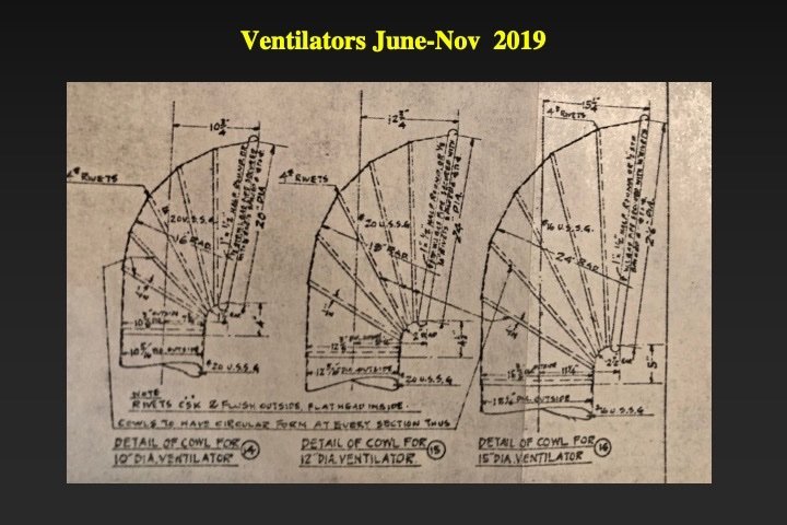
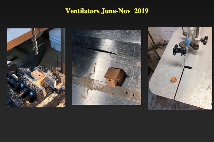
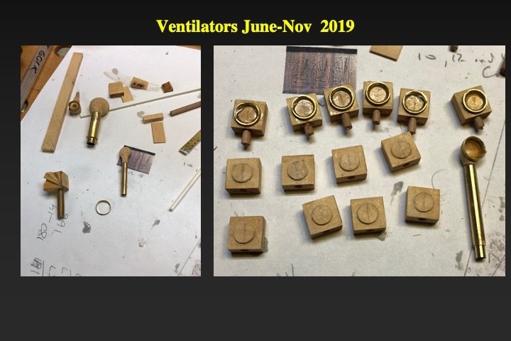
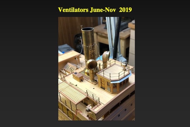
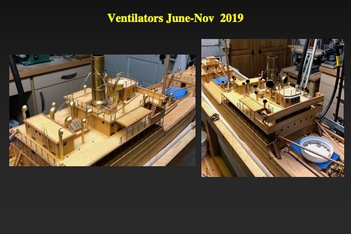
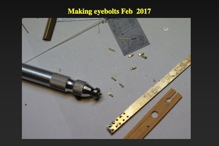
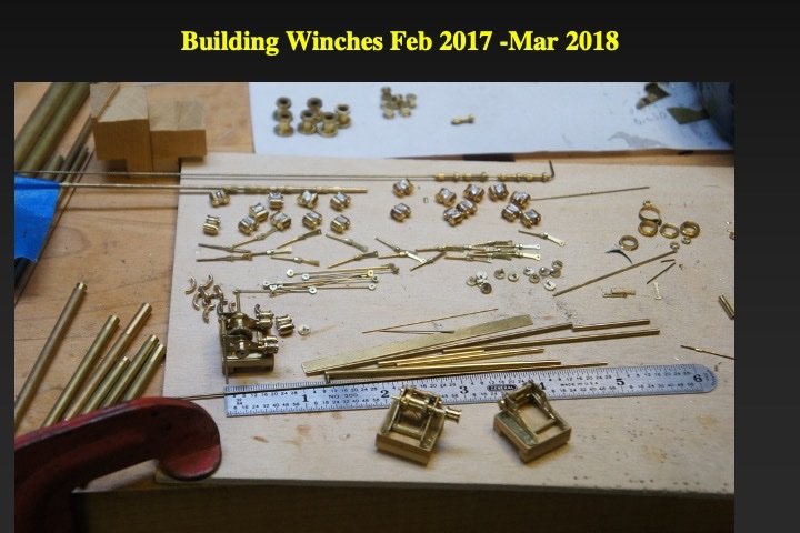
Thank you for the comment. I'm sorry that I didn't take more pictures of the process(es). Most of what I do is pretty straightforward: using pliers, hammer, miniature vise/anvil, lathe, epoxy, silver solder. My first "secret" is that I buy a lot (!!) of brass: rods, tubes, wires, I-bars, T-bars, angle strips etc. in many dimensions - to have at hand any material that I might need. My second "secret" is that I use pictures, historical plans and plans I draft myself to generate scale parts from all that brass. My third "secret" (and the major one) is that I practice (a lot!) making parts until I have a method that generates the "best" part. When I enter the "production" phase I make many extra parts (breakage, wastage, dropping/losing). I made ten winches; So I could pick the "best" eight. Making the ventilators was a good example of this process. The actual ventilators were made of bent steel plates: E.g. they were not smoothly rounded (see the photo below of the ventilator plans from the contemporary EFC plans. I simply did not have the skills to assemble sections of brass tubing to generate the appropriate ventilator cross section/profile. And I needed a method that produce 26 ventilators of multiple sizes. So I used boxwood (and brass) to make the ventilators. I glued together wedges of boxwood with the dimensions of the needed ventilator sections. I epoxied a brass ring to the forward boxwood section and then shaped the exterior of the ventilator. Very carefully, I used my Foredom tool with various sized bits to carve out the interior of the ventilator. After painting the interior black, it is very hard to tell that ventilators are not completely hollow. A scale brass tube comprised the ventilator shaft. The ventilator exterior with coated with (now unavailable) FloQuil brass paint.
-
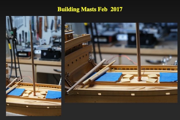
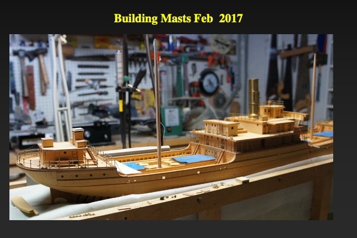
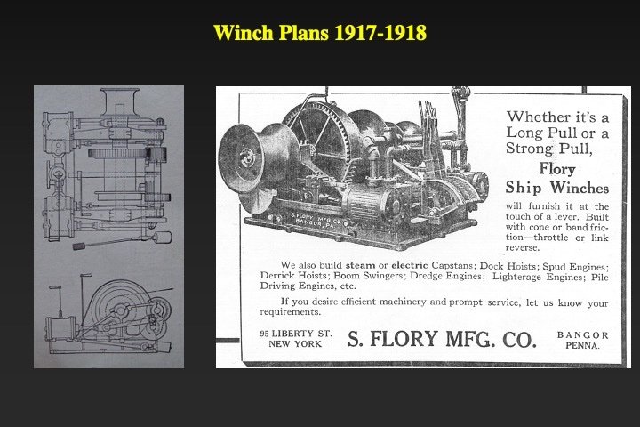
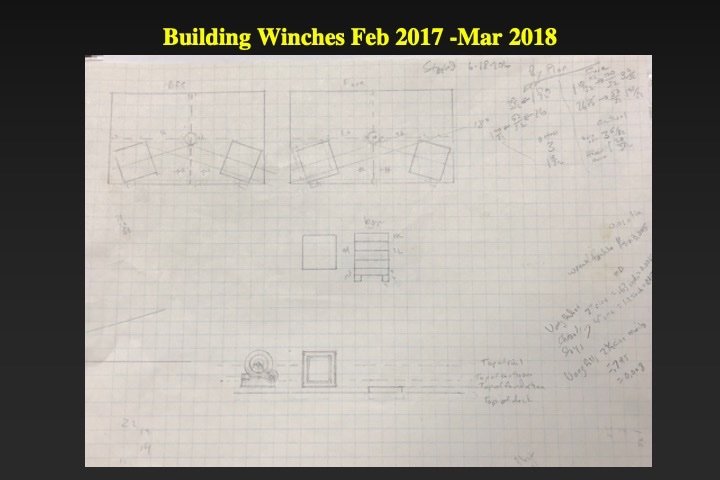
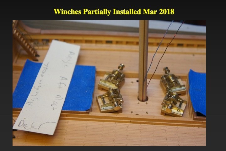
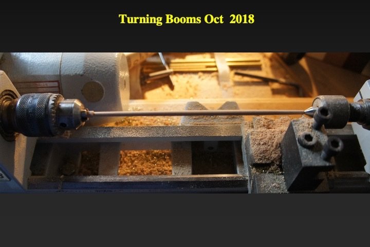
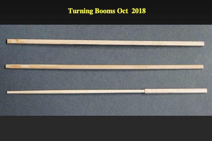
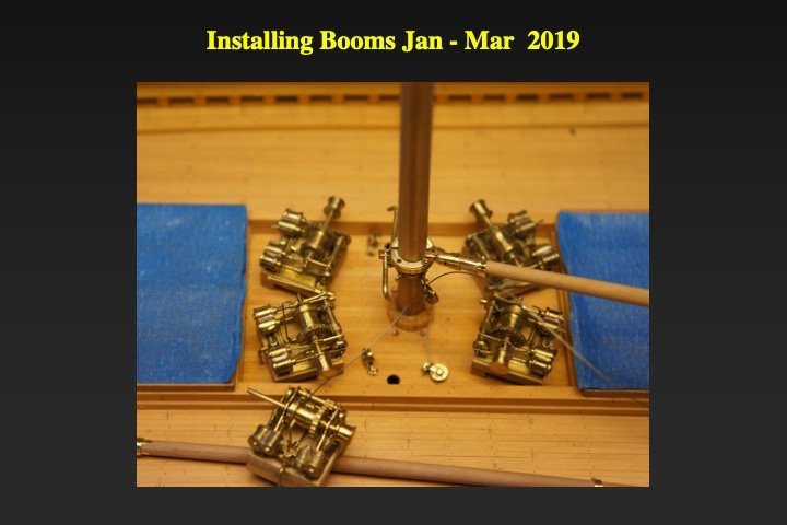
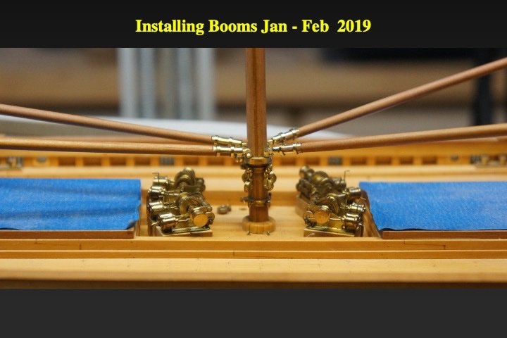
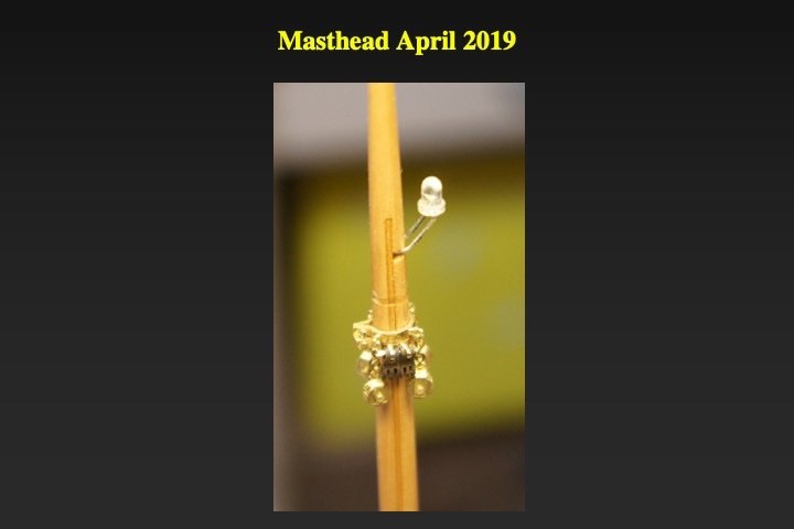
The two masts were turned out of applewood on a Unimat lathe. Slots were cut on the port and starboard side of each mast to hide the wires of the masthead navigation lights. The slot was later filled with a narrow applewood strip. One of the slides shows a close view of the near-final masthead The winches were next. Making the winches took over a year. The winches were modeled based on pictures from the 1918 journal International Marine Engineering as well other documents. The slides illustrates the plans that were used for the eight winches. Each winch was composed of over 30 brass parts, the were soldered or epoxy together. The cargo booms came next. The various mast and boom fittings were carefully modeled on the detailed specifications provided in the rigging plans prepared by the Emergency Fleet Corporation for the Ferris-Type wooden steamship.
-
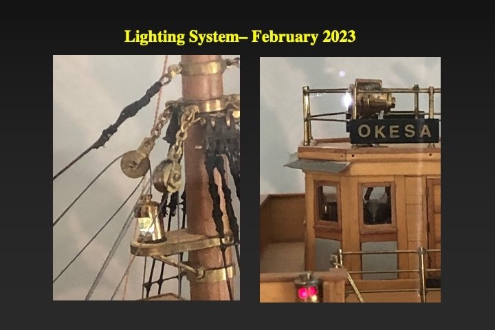
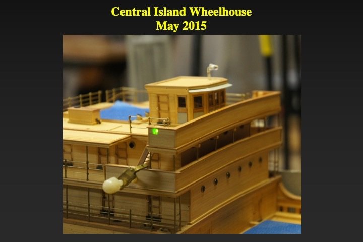
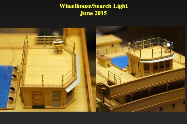
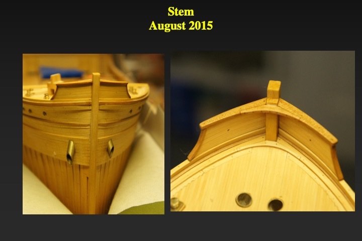
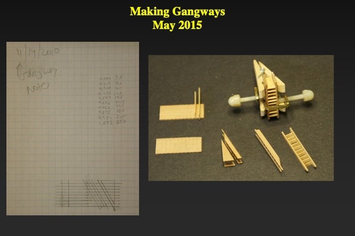
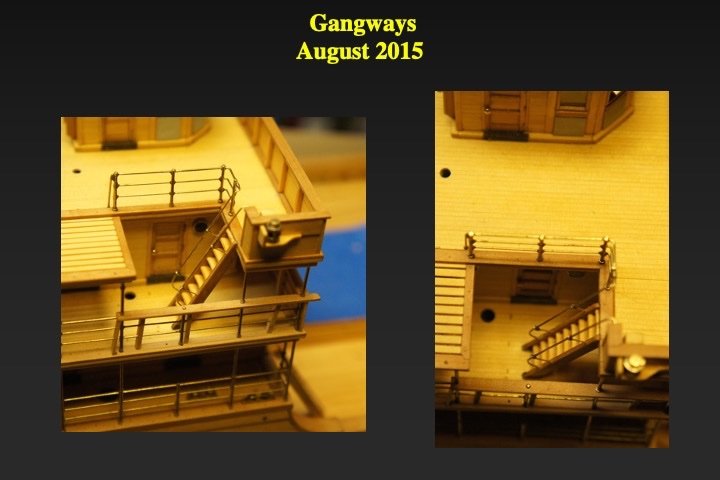
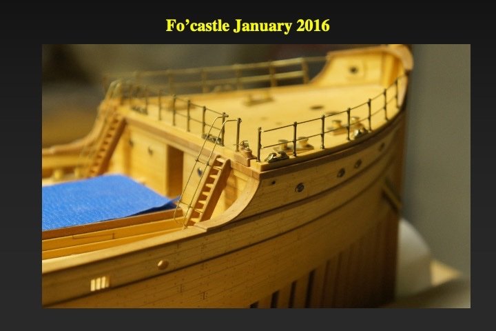
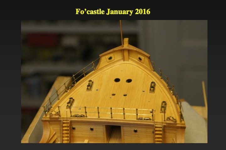
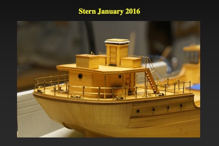
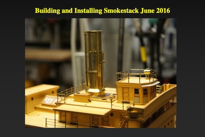
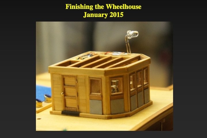
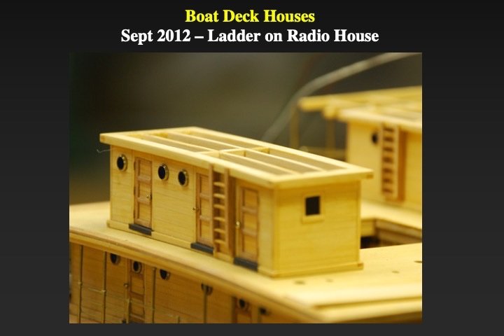
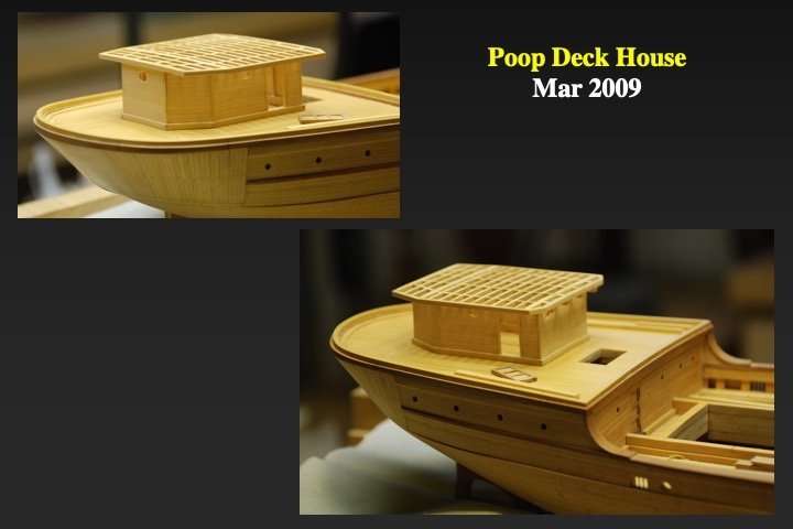
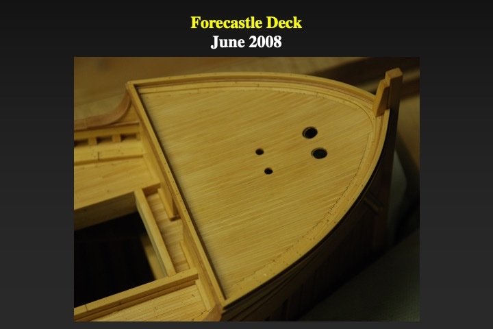
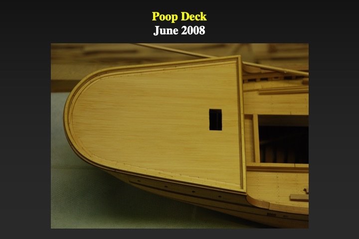
Before rigging commenced the final fitting out of the hull and cabins was completed. Railings and the searchlight were installed on on the wheelhouse. The searchlight was created from turned brass tube; the leads for the LED inside the searchlight were enclosed in its mounting. The stem was completed and the forecastle rails installed. The poop deck and poop deckhouse fittings were completed. The slide illustrates how the gangways (ladders) were built. Slots were placed in 3/4 inch wide strips of applewood and boxwood stairs were glued into the slots. After the glue cured, the block was cut at the appropriate angle to make the gangways. The rough gangways were trimmed, glued in place and the gangway railings installed. From contemporary pictures and from the Ferris-type wooden steamship plans from the National Archives, I was able to reconstruct the smokestack. I made the basic smokestack and its mount using various dimensions of large diameter brass tubing. An etched outside ladder, a vent for the boilers, a steam whistle and eyebolts for its supporting stays were soldered on and the smokestack was installed.

-
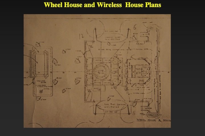
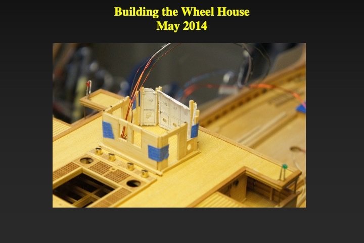
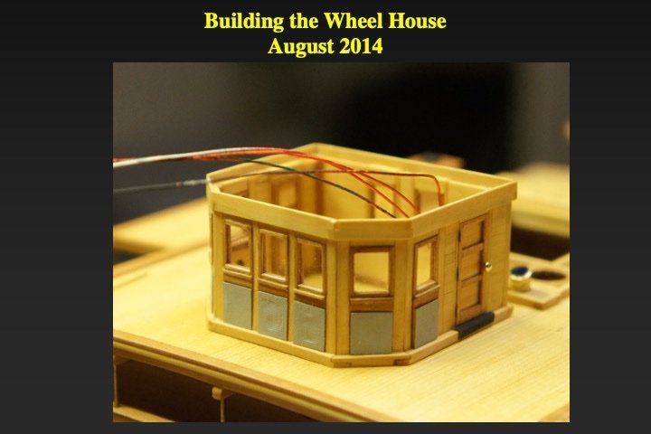
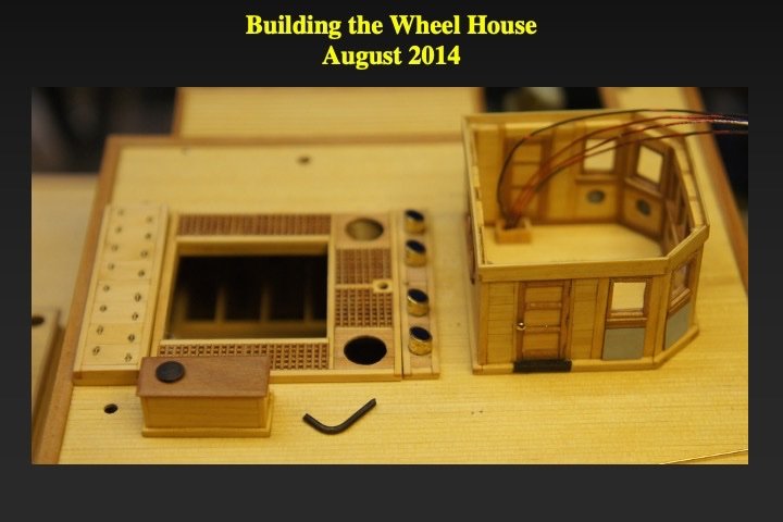
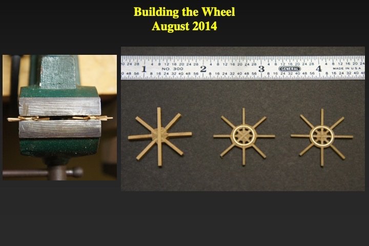
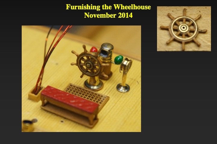
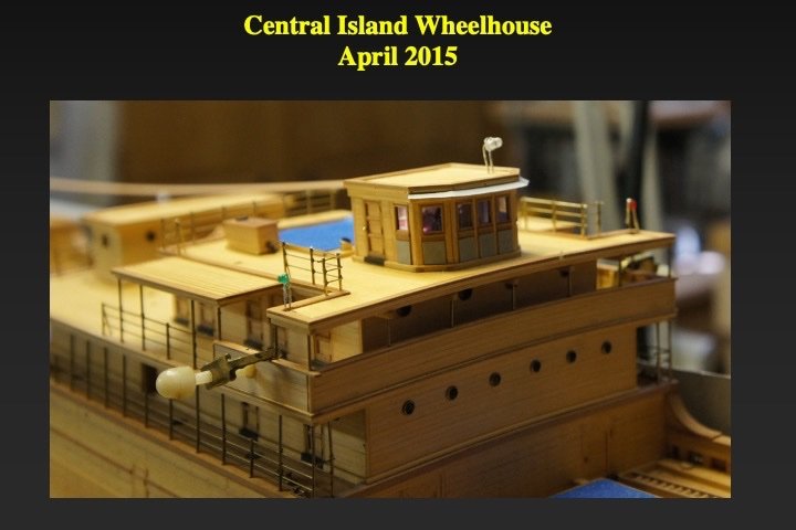
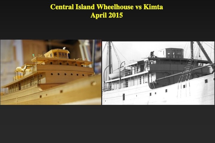
Yes there was a bit of chopping - but the amount a metal removed was quite small. I tried a jig with a needle file and that method worked;. However, I had about 100 stanchions to make and cutting them 10 at a time with saw was easier - even with the wastage. I had fun building and furnishing the wheelhouse. Throughout the build, I knew I wanted to furnish one of the ship's cabins - and the wheelhouse was my choice. The lighting system was designed to illuminate the wheelhouse (like a dollhouse) as well as the search light on top deck above. The wheel house was built like the rest of the cabins - with six sides. The actual wheelhouse had one interesting feature: Below the square ports, the forward three bulkheads contained large round openings (covered with canvas) so that the wheelhouse officers could communicate with the outside crew with just a little "yelling." I modeled that canvas with cloth. The square ports were glazed with clear plastic. One of my modeling "heroes" was Steve Wheeler. He would model upholstered seats/benches by carving and painting appropriate blocks of wood. In memory of Steve, I built the wheelhouse bench in the same way (from carved boxwood). The pictures show how I assembled the wheel (it took four tries before I achieved one that looked just right). I built the binnacle/compass and the engine room telegraph using contemporary (1918) photographs as guides. I had several photos of the Okesa and the Kimta (a sister ship). For fun, I took a shot of the model from the same perspective as that of the Kimta at a similar stage of construction.


-
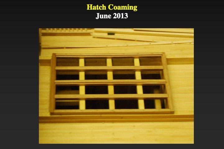
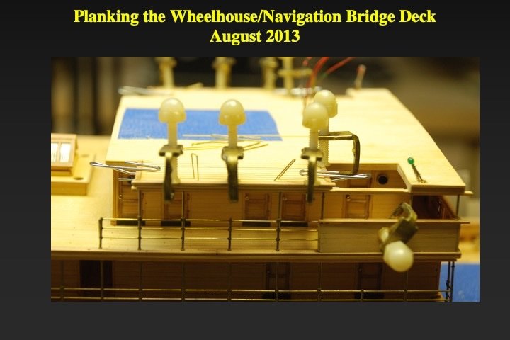
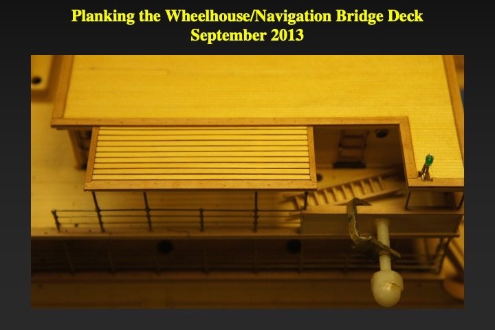
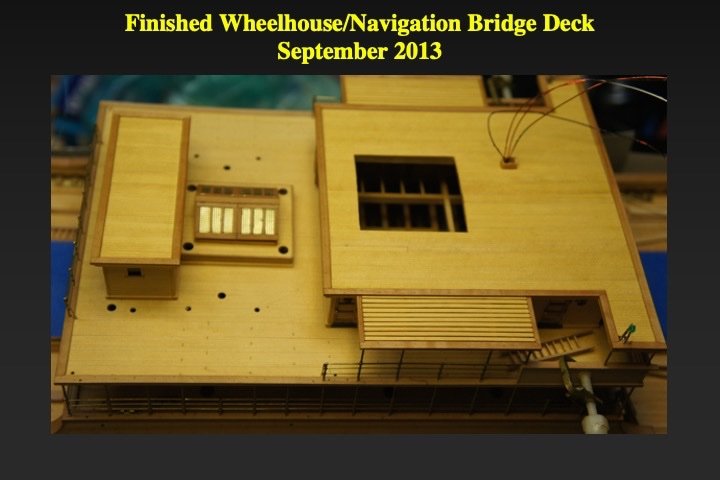
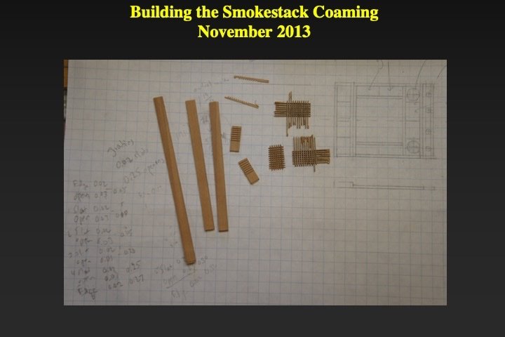
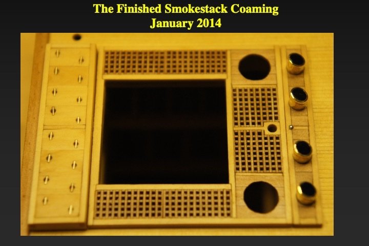
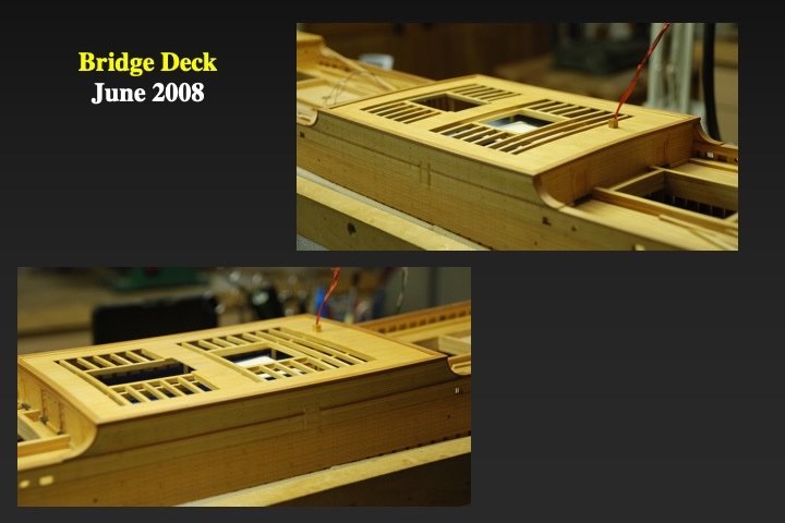
Cargo-hold hatch coamings came next. They were then covered with blue tape to keep dust out of the hold. The planking of wheelhouse/navigation bridge deck followed. Note the lathes that will support the skids for a starboard lifeboat. Port skids will support a workboat. The jutting green LED, will become the starboard navigation light (A red LED is on the port side). The smokestack coaming was drafted, assembled and installed. I made the gratings in the usually way: Slotting applewood planks, cutting strips and assembling. The large holes are for the boiler room vents. The foreword-slanted brass tubes with the plastic insert are the skylights for the galley stoves that were just below.

-
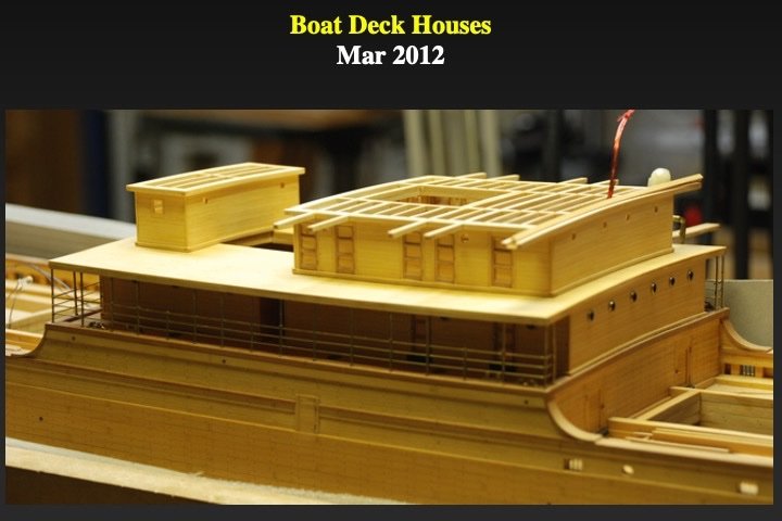
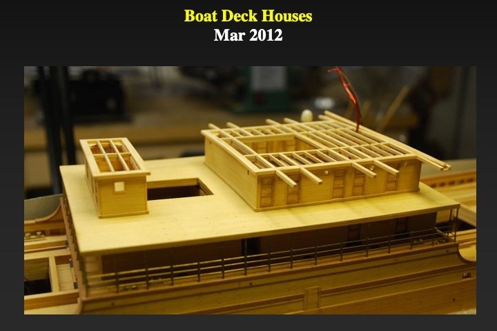
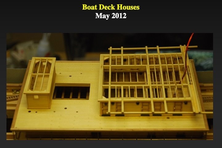
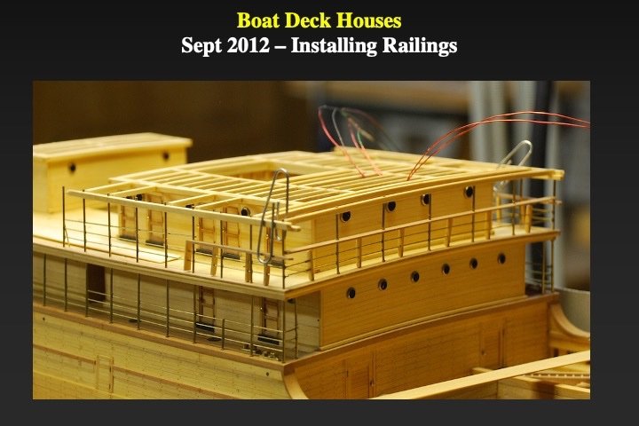
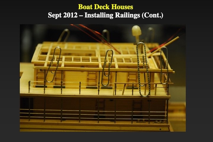
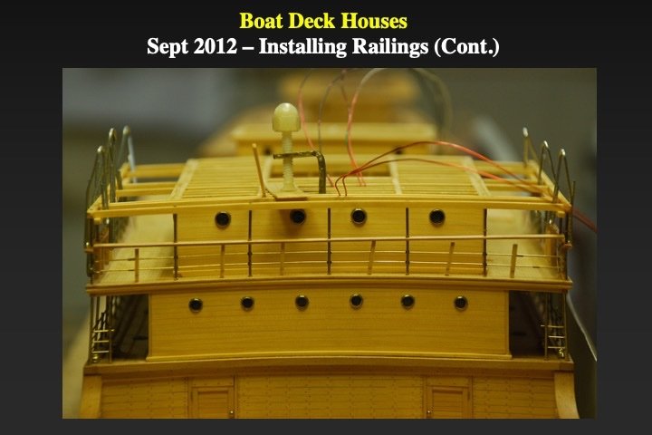
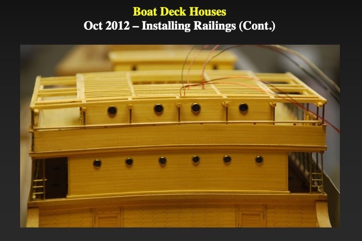
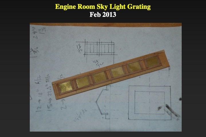
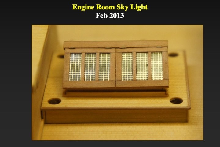
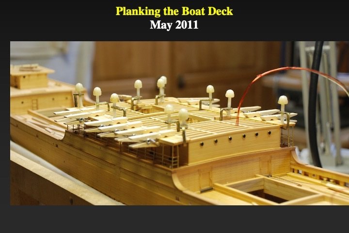
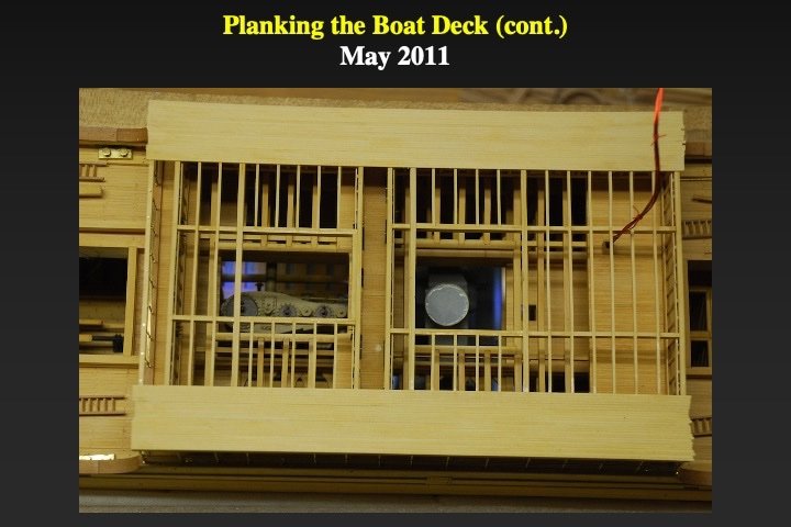
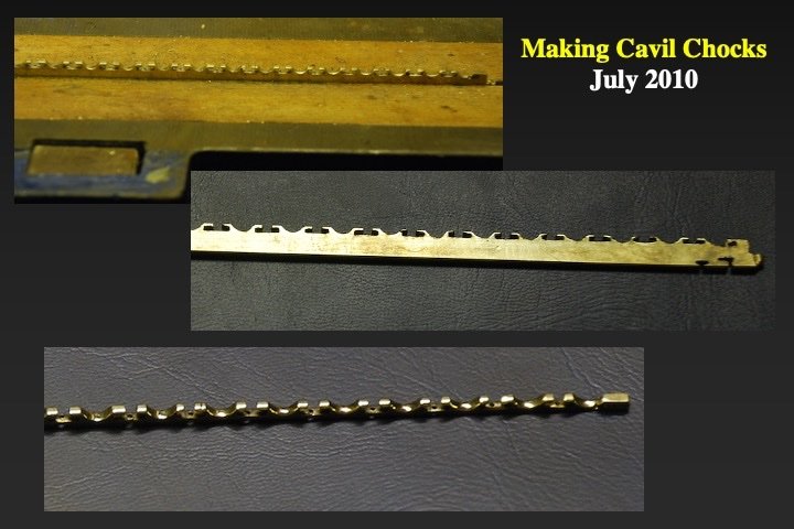
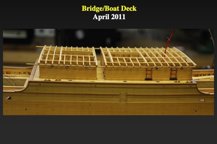
I suppose that they are technically "guard rails." In some cases they support the deck above, so I like the terms stanchions and railings. I used a 0.020" circular slotting blade on the Bynes saw with the cutting depth as low as possible. Even so, there were many "failures" with a slot too deep or too shallow. The next step was the assembly and installation of the boat deck house and the radio house. The railings were similar to the bridge deck railings. However, on the actual ship, the fore-most railings/stanchions were covered with a wood/canvas "bulkhead" to reduce incoming waves/water. From the pictures it can be seen how those "bulkheads" (without the canvas) were installed. The engine room skylight was installed next. The "munitins" were modeled using sheets of etched brass and the "glass" was modeled using a thin layer of clear epoxy applied to the underside of the brass; with Saran wrap on the top to generate smooth finish. After the epoxy cured, the saran wrap was removed. The circular holes in the skylight are for future ventilators

-
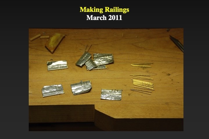
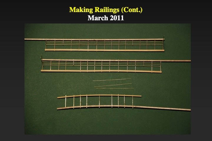
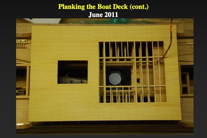
It took me nearly a year to figure out how to make realistic scale railings. I tried both standard soldering techniques and well as resistance soldering. Neither yielded results that satisfied me (maybe my technique was poor...). Finally, I tried this method: I cut scale brass wire into the length needed for the stanchions. About ten stanchions were aligned (flat) on aluminum tape. Using my Jim Bynes table saw, I cut 2 or 3 slots (depending on position on the rail) in that bunch of stanchions (see photograph). Jigs were made that modeled the fore-aft and port-starboard camber of the ship and kept the stanchions in their correct positions. Scale brass for each of the rails was temporarily superglued into the stanchions slots. I used brass dust - mixed with epoxy - to model the stanchion-rail joints. Once the epoxy cured the rails were ready. I used the same jig to accurately drill holes in the plank-sheer and the boat deck beams to install the railings. A small brass ring was used to model the lower joint of each stanchion. A similar method was used for all the railings on the model. Once the bridge deck railings were attached it was time to plank the boat deck.


- 40 replies
-
- 16
-
-
-
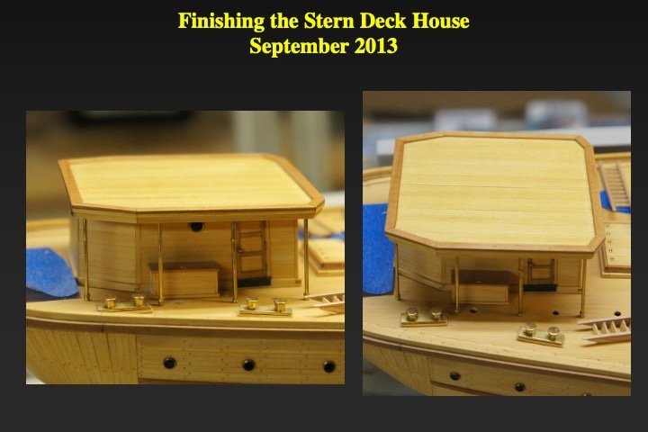
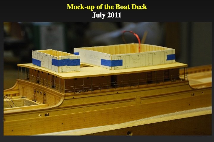
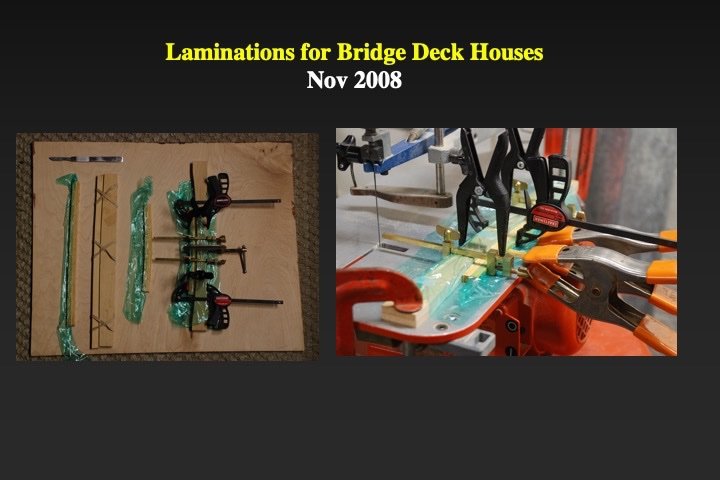
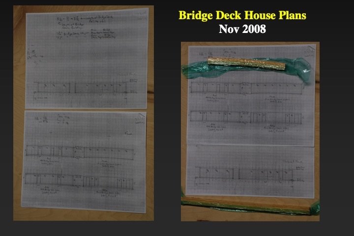
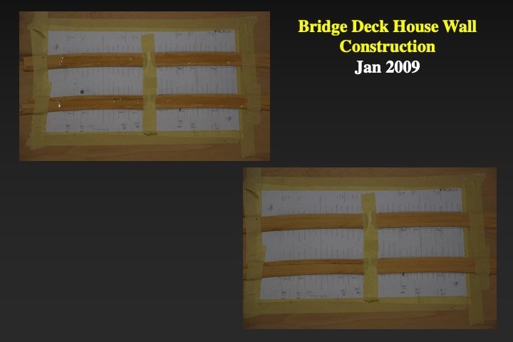
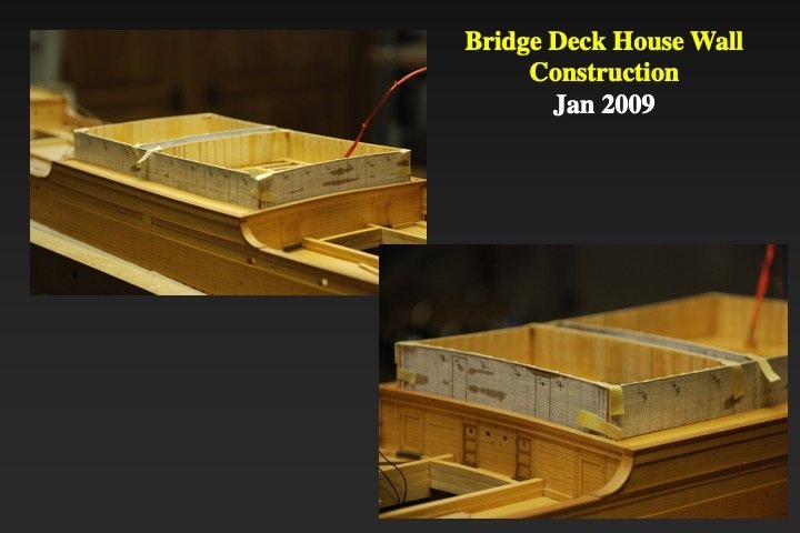
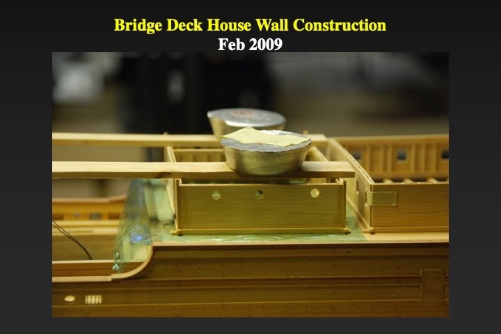
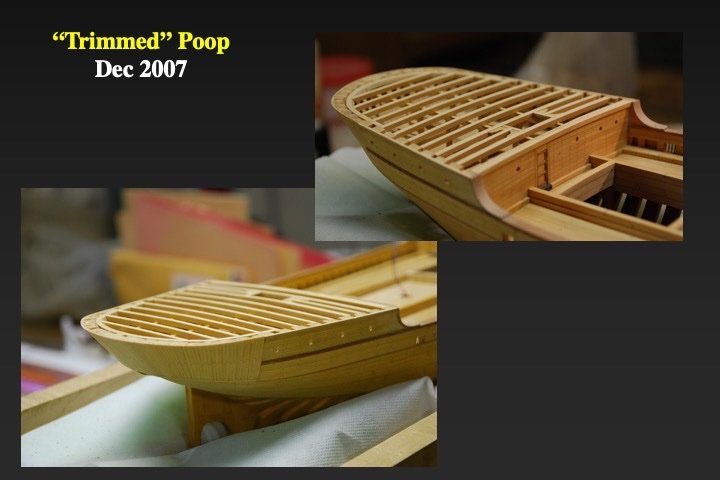
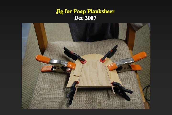
I drafted paper plans of the bridge and poop deck houses. To plank the bulkheads of the houses I laminated boxwood strip with the thickness the same as the as the width of the planks. I then glued several strips together and clamped them to jigs that matched the fore-aft and port-starboard camber of the decks. Once the epoxy had cured, I used a miniature table saw to cut long wall sections. These were rubber cemented to the paper plans and then the holes for the doors and portholes were cut out. Then the walls were assembled.

-
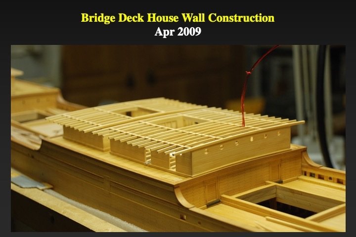
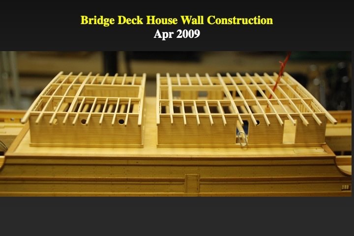
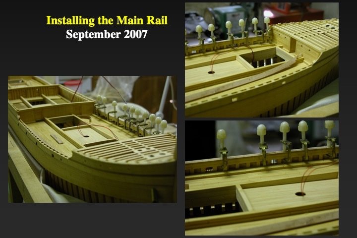
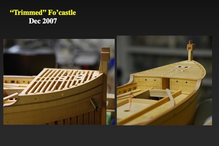
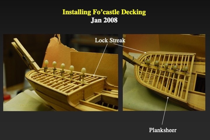
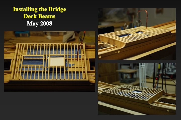
The next steps were the installation of main rail. That was followed by trimming, installing the beams and laying the decking for the poop, bridge and forecastle decks. There will be more on the engine and boilers in a later post. The blue tape in the installing the bridge deck beams was a temporary measure to keep debris/dust out of the engine room and boiler room.
.jpg.7de2712b3fe62cad9add2a686bb69569.jpg)