
HOLIDAY DONATION DRIVE - SUPPORT MSW - DO YOUR PART TO KEEP THIS GREAT FORUM GOING! (Only 36 donations so far out of 49,000 members - C'mon guys!)
×


MisterMeester
-
Posts
83 -
Joined
-
Last visited
Content Type
Profiles
Forums
Gallery
Events
Everything posted by MisterMeester
-
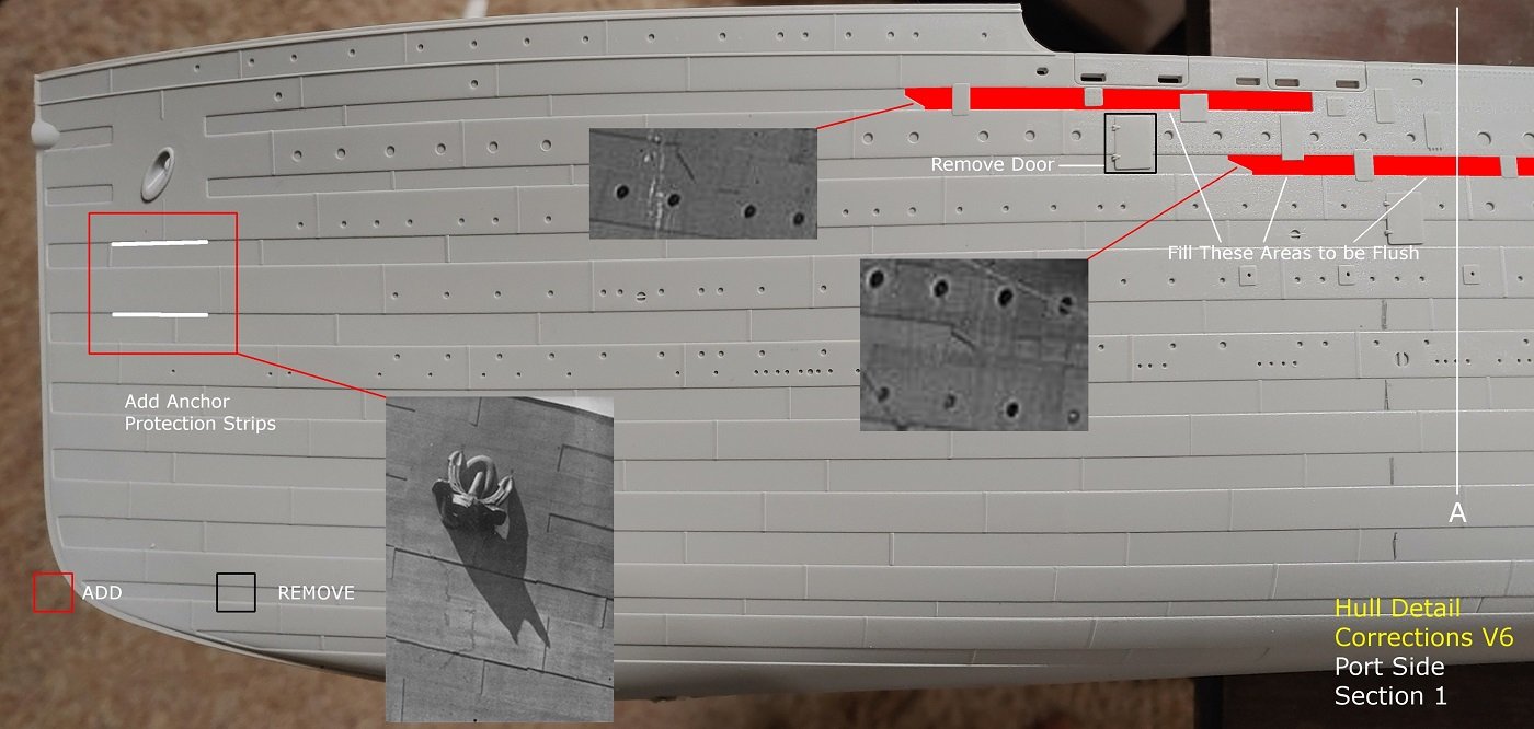
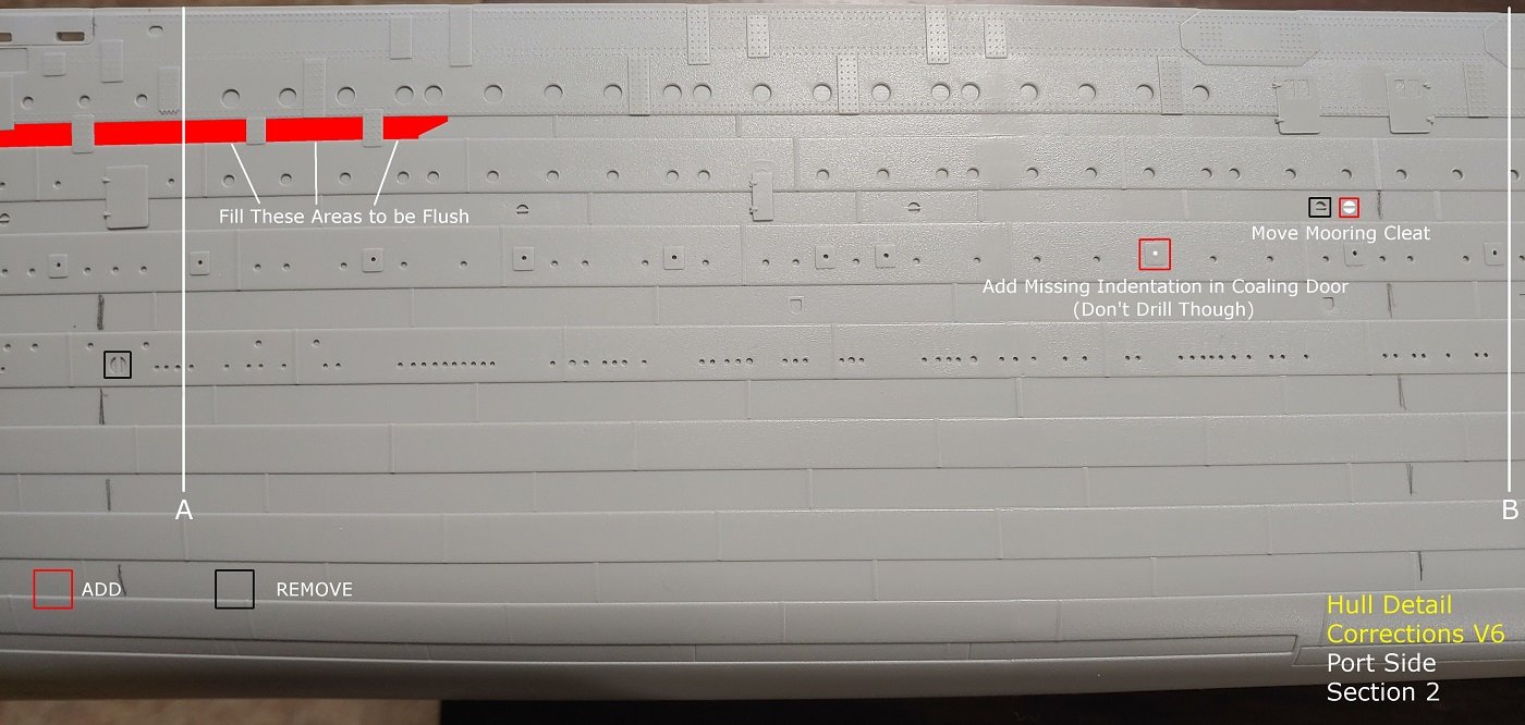
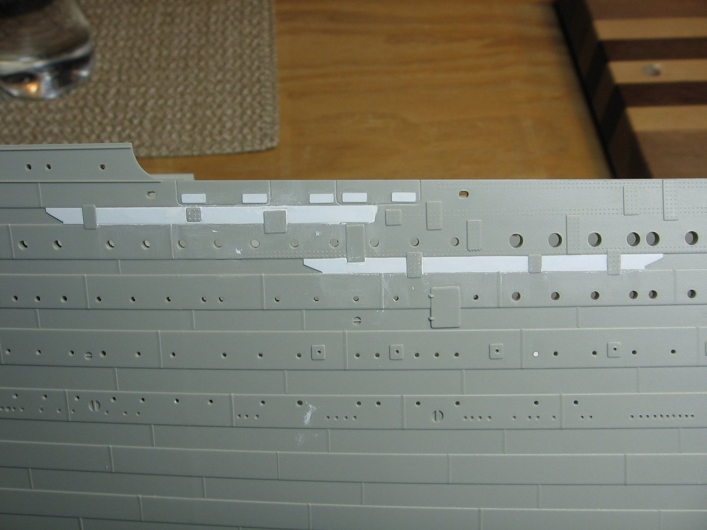
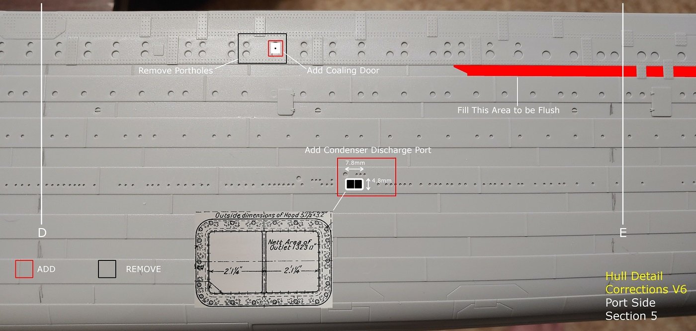
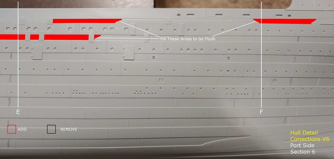
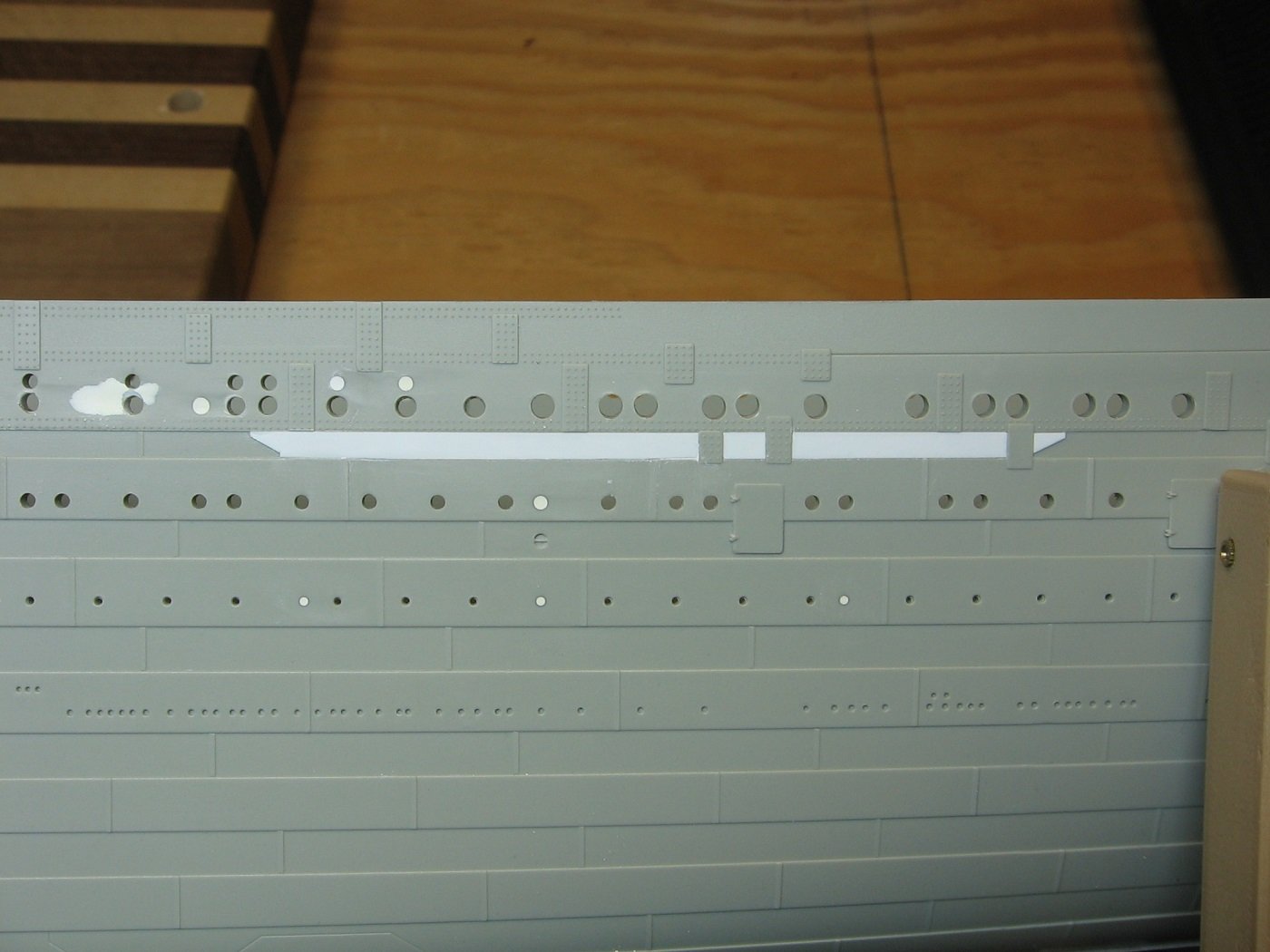
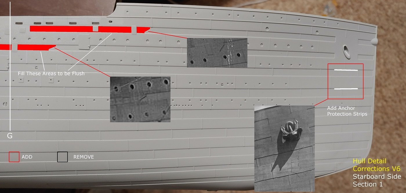
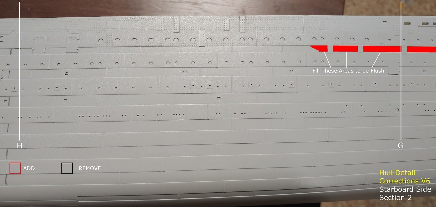
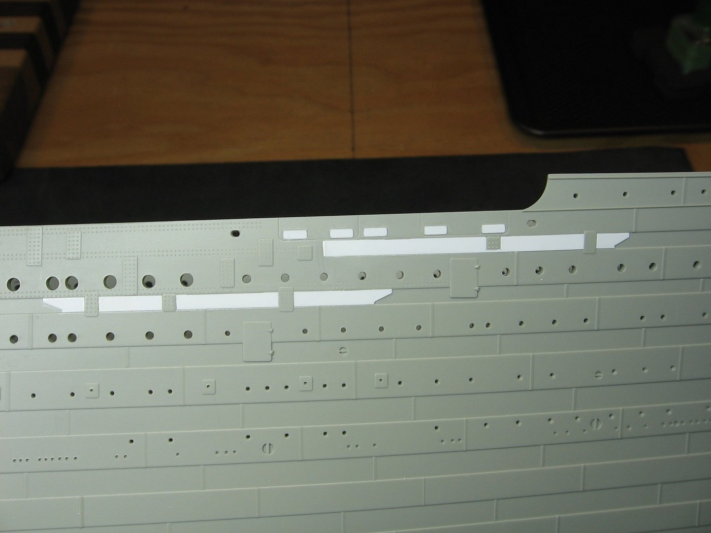
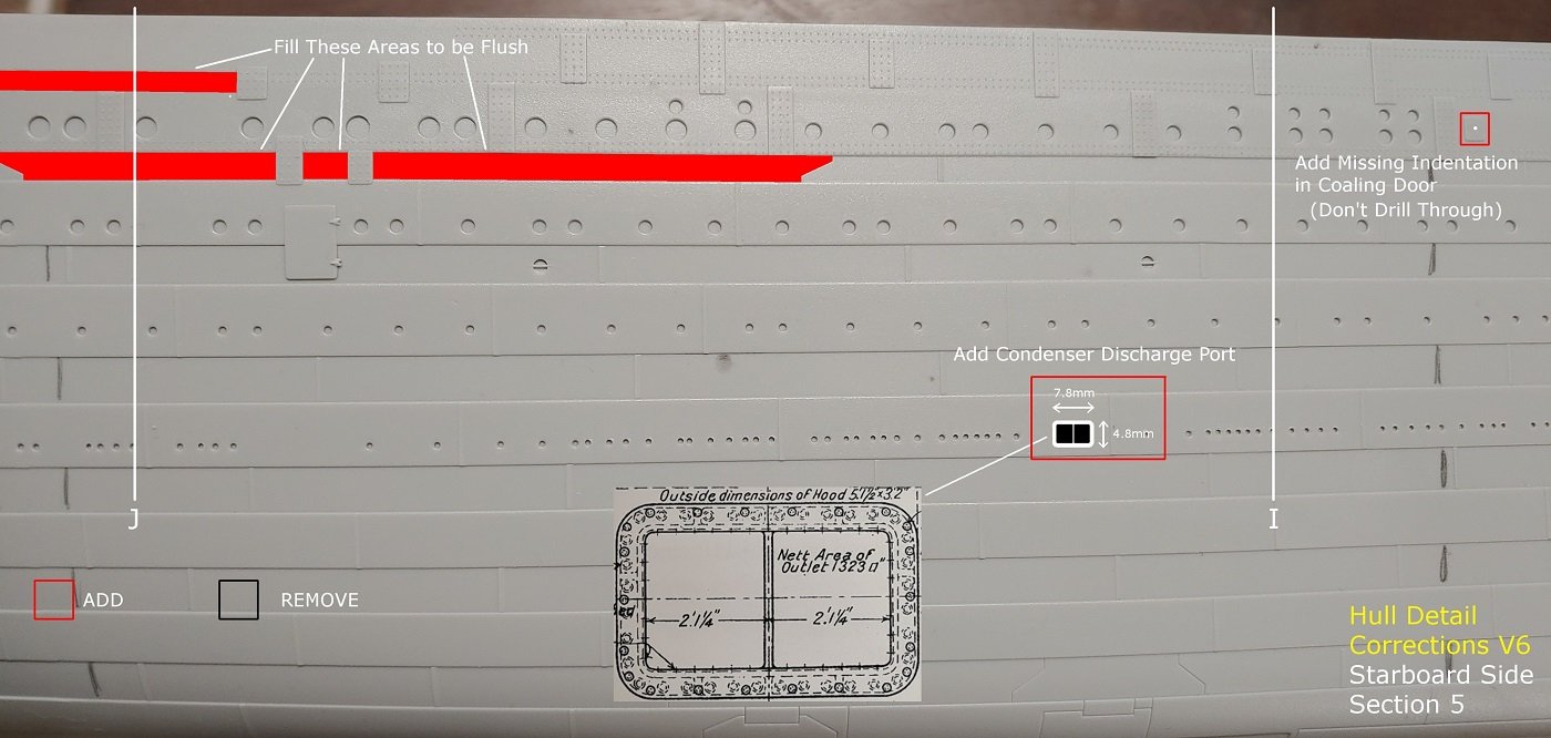
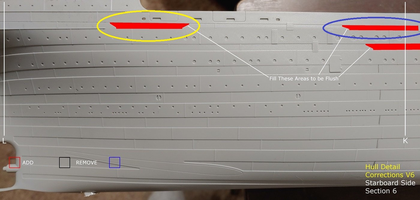
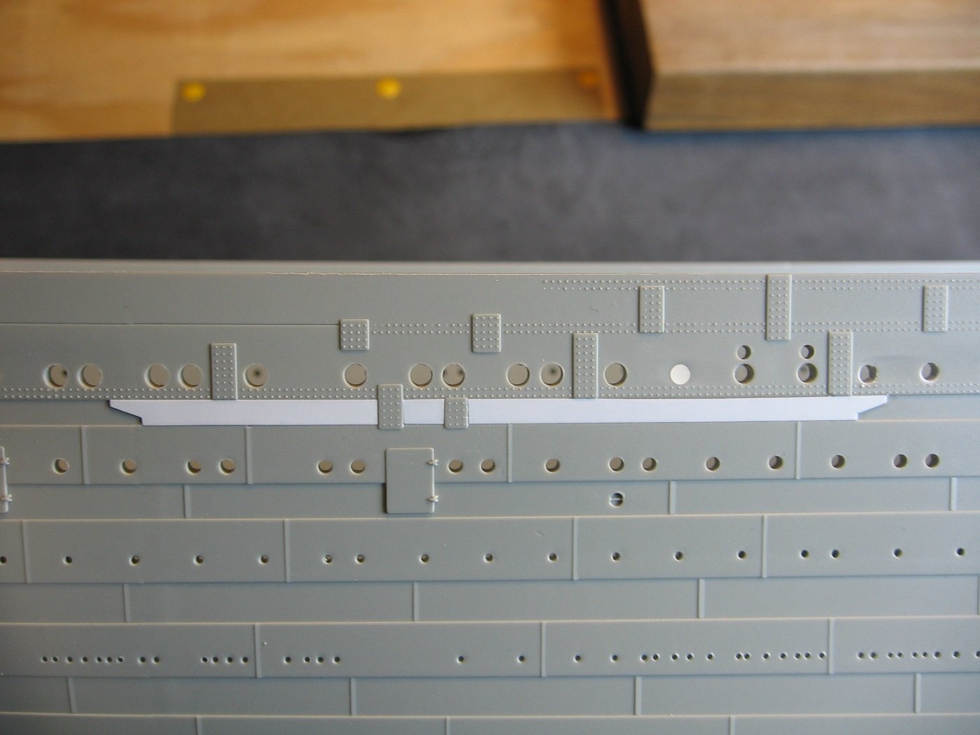
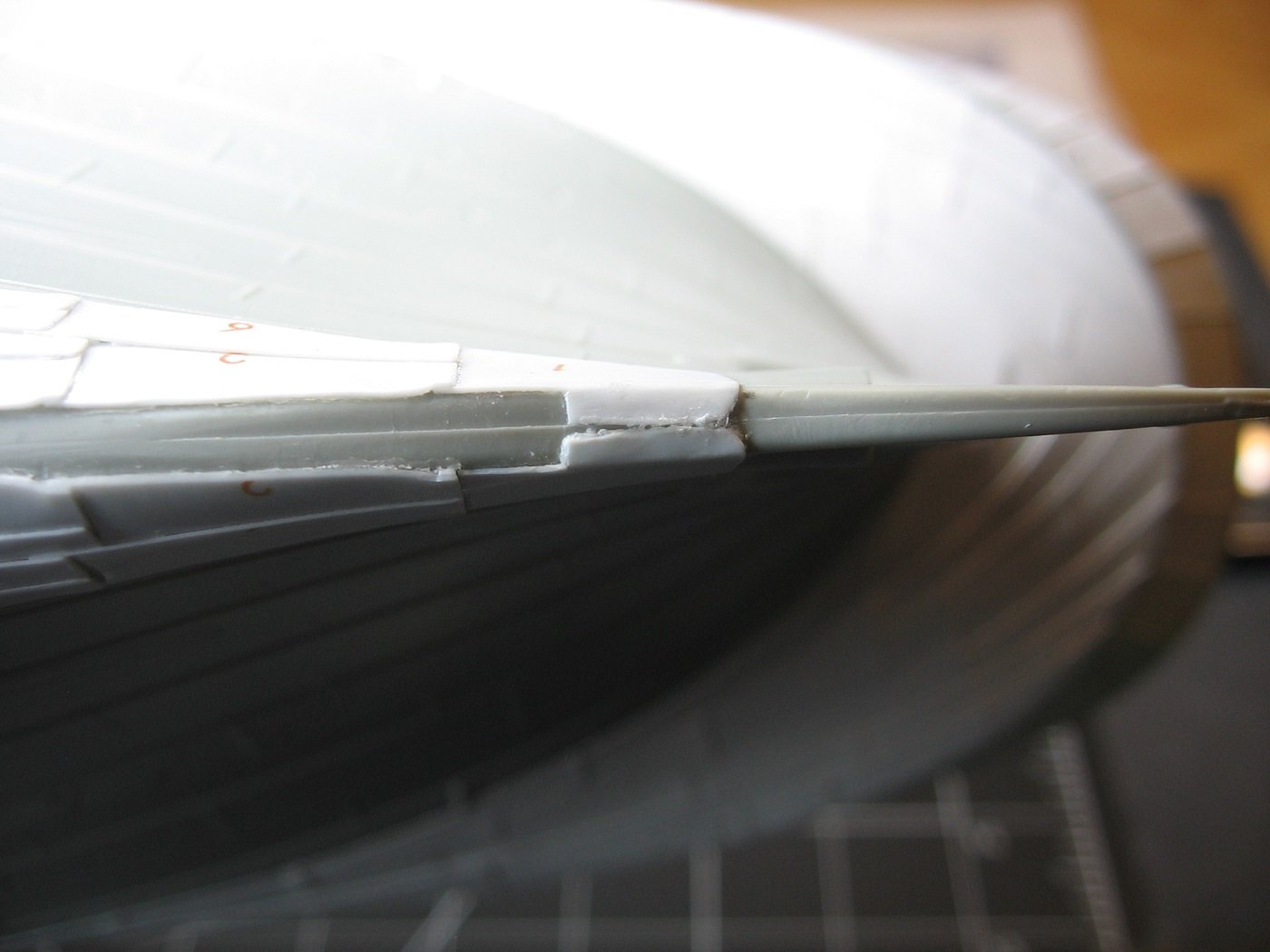
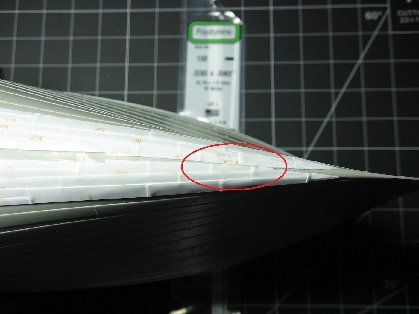
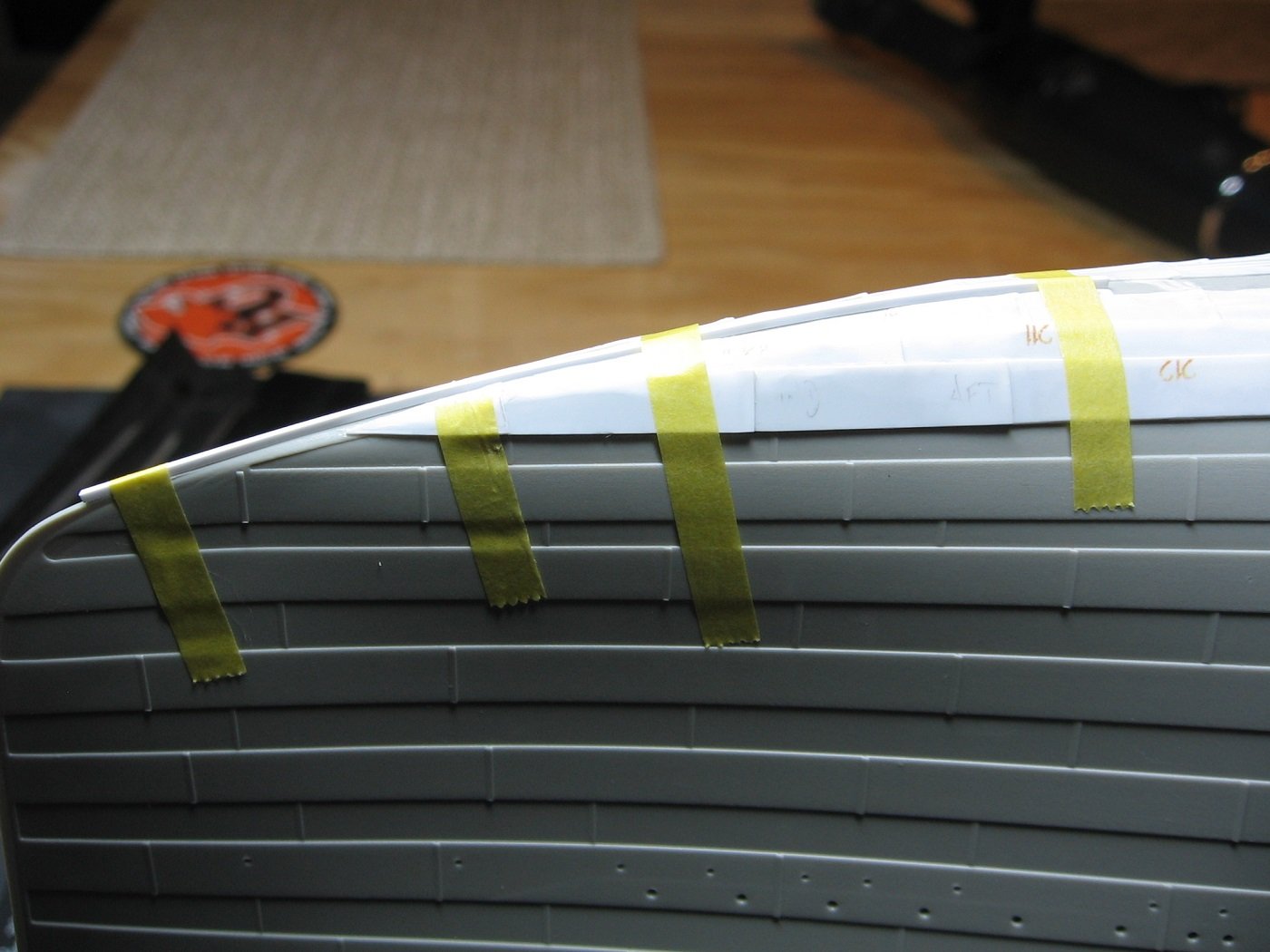
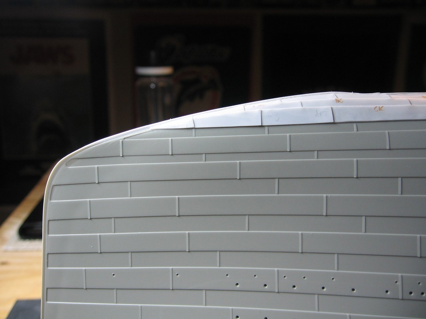
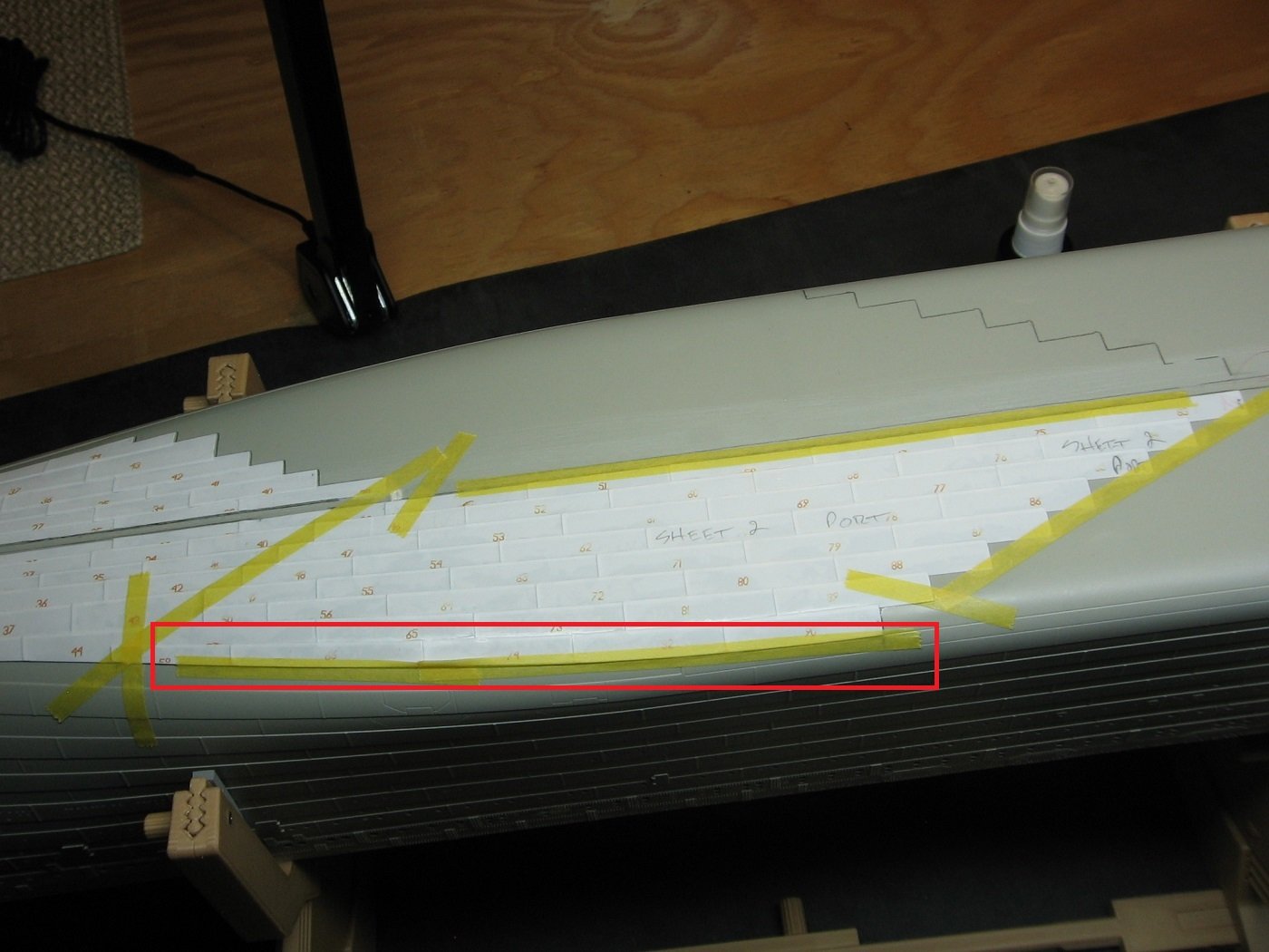
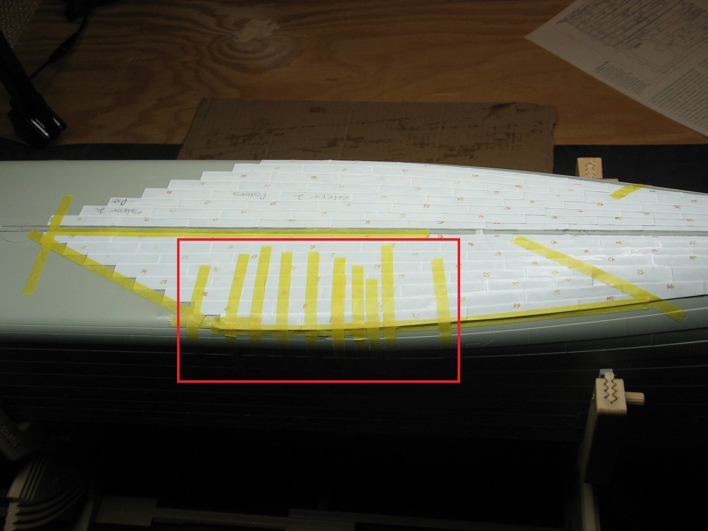
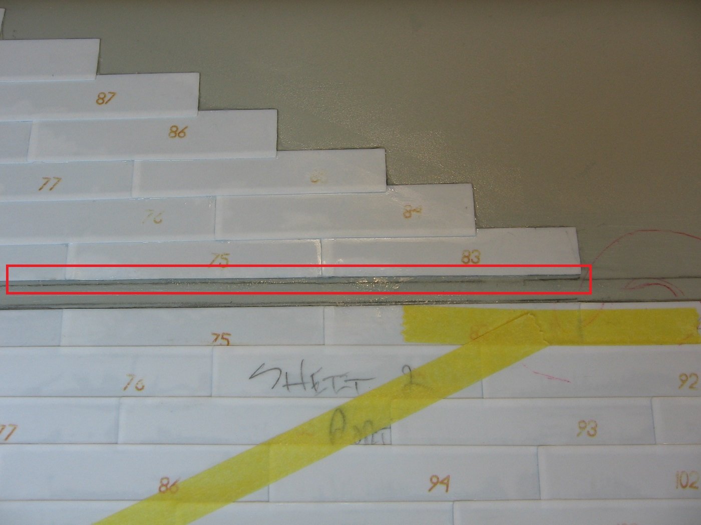
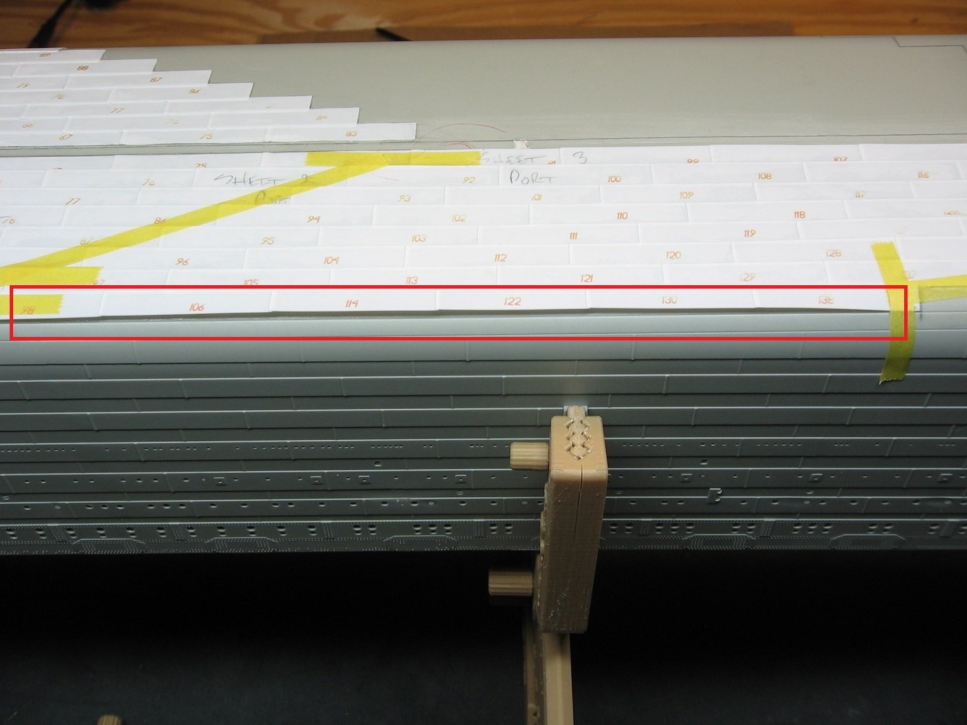
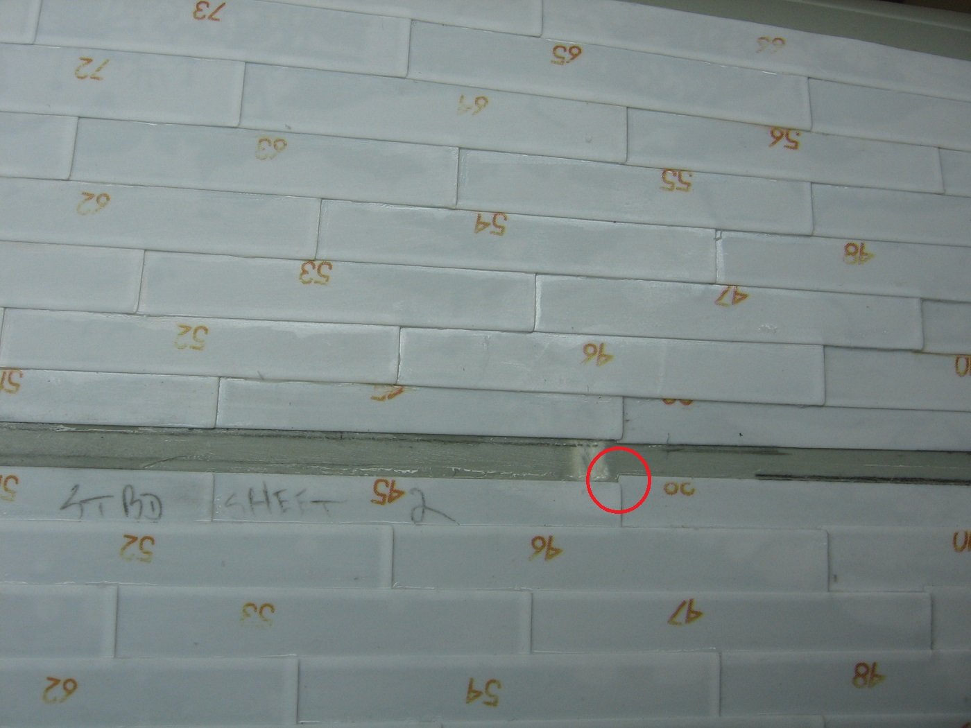
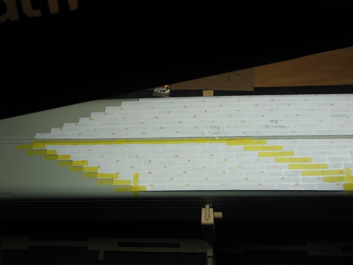
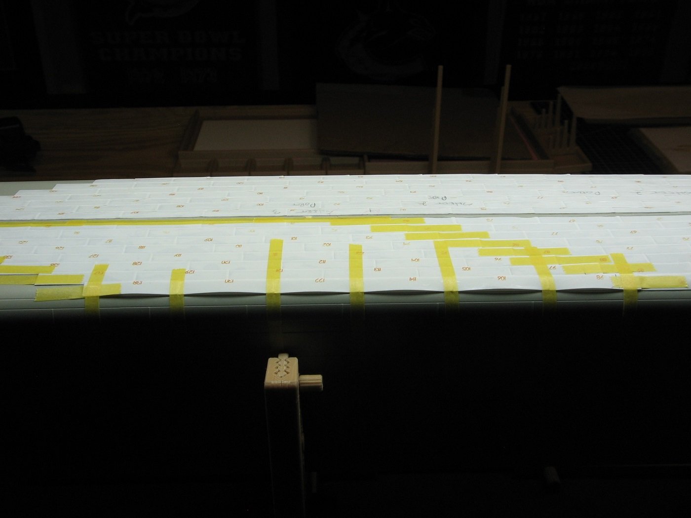
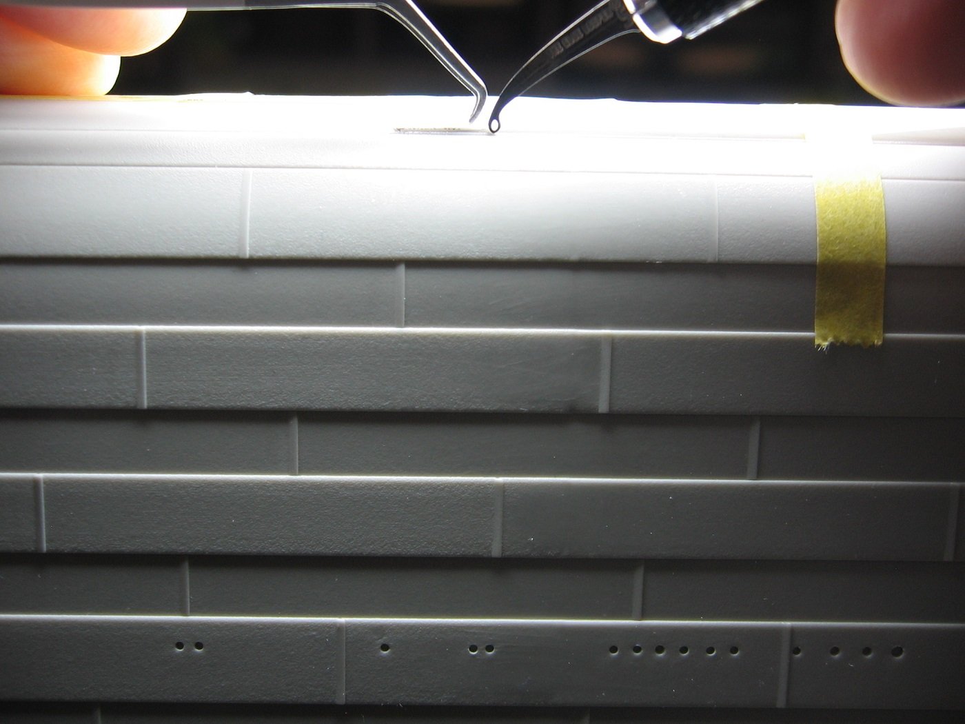
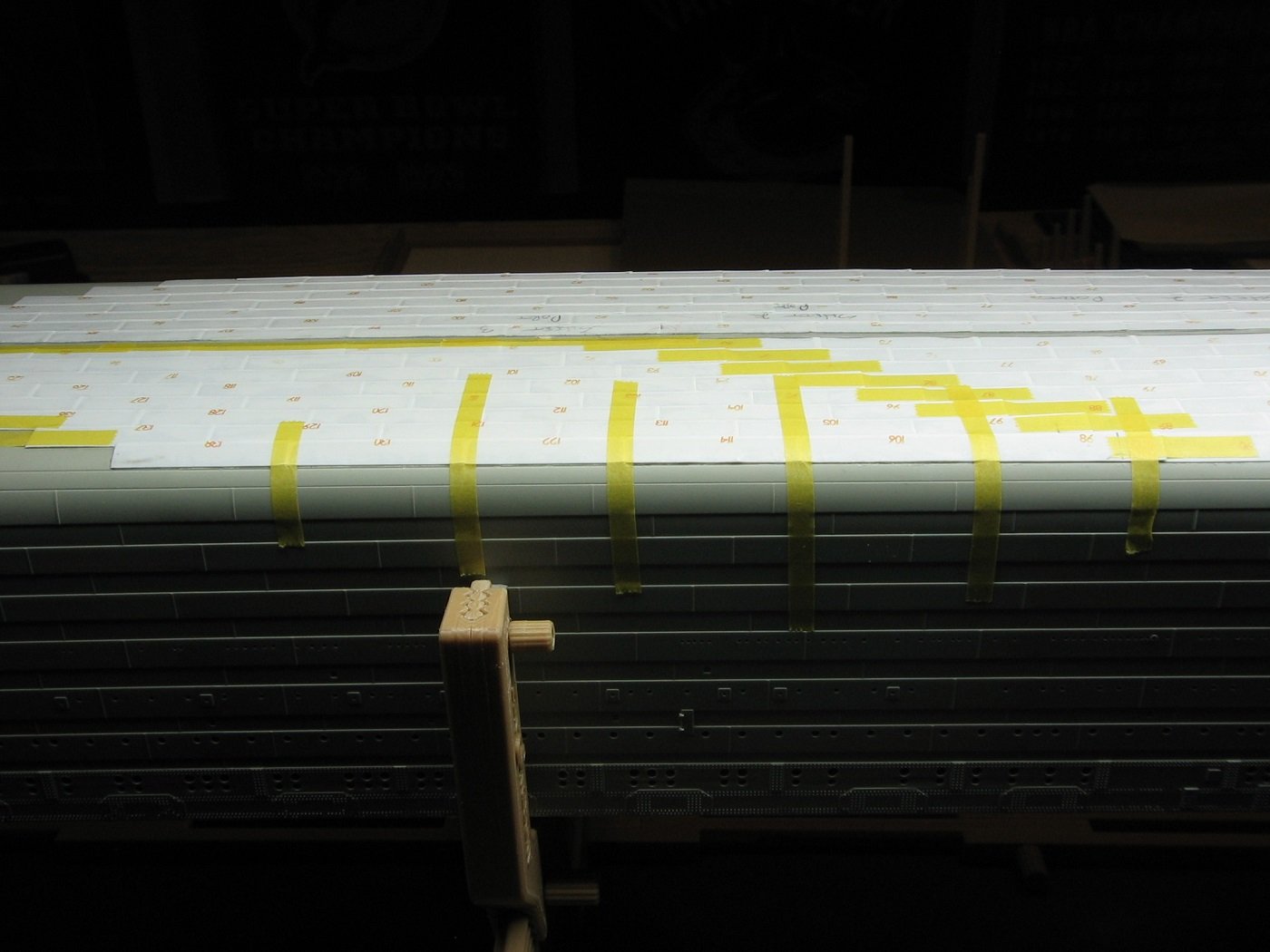
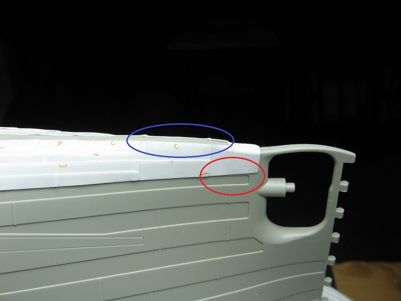
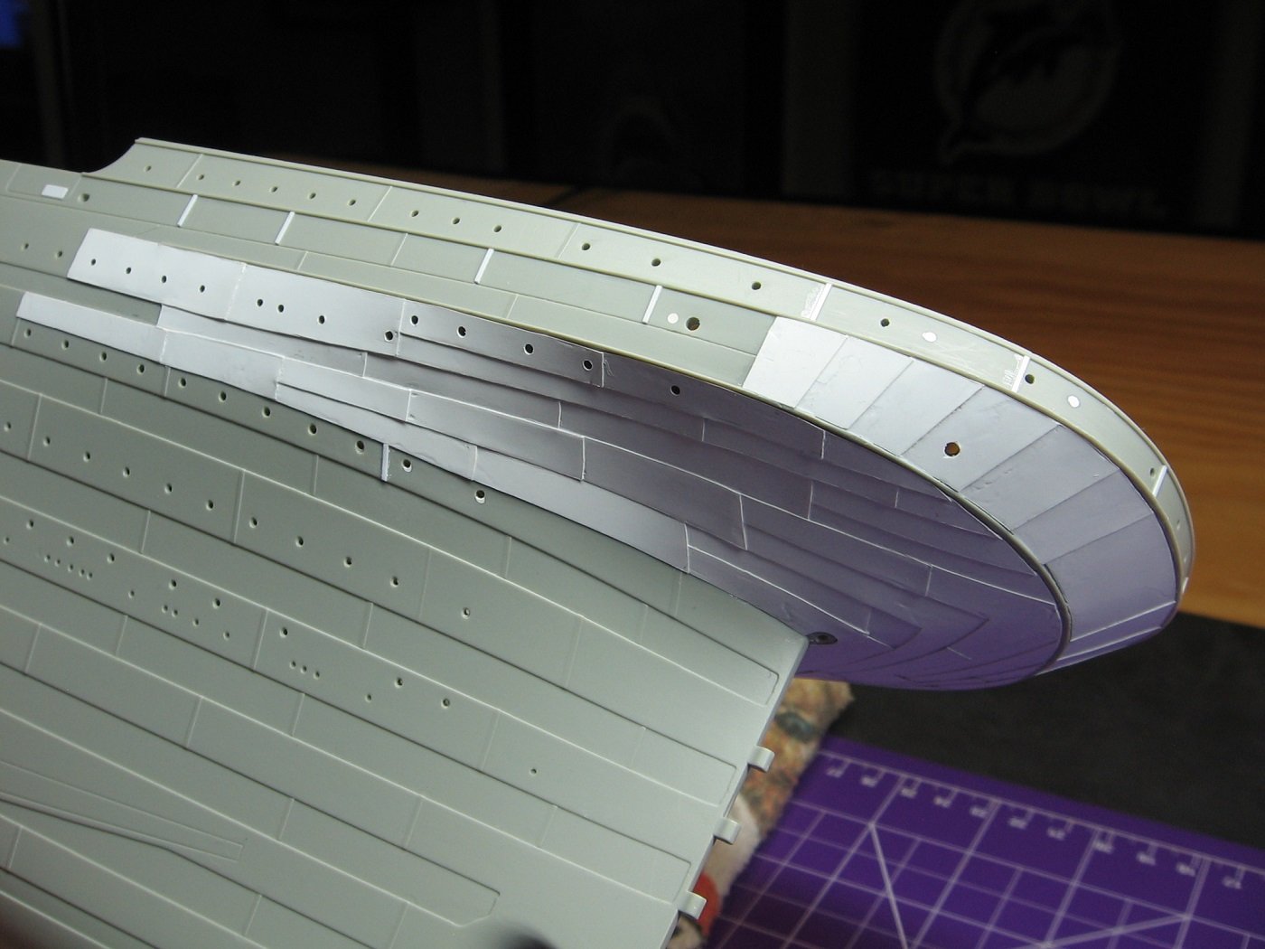
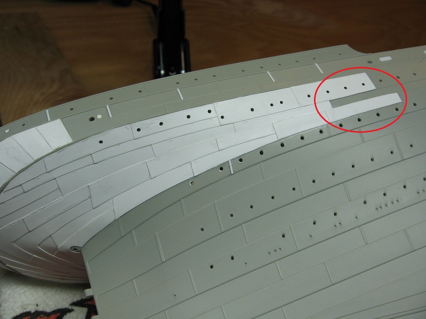
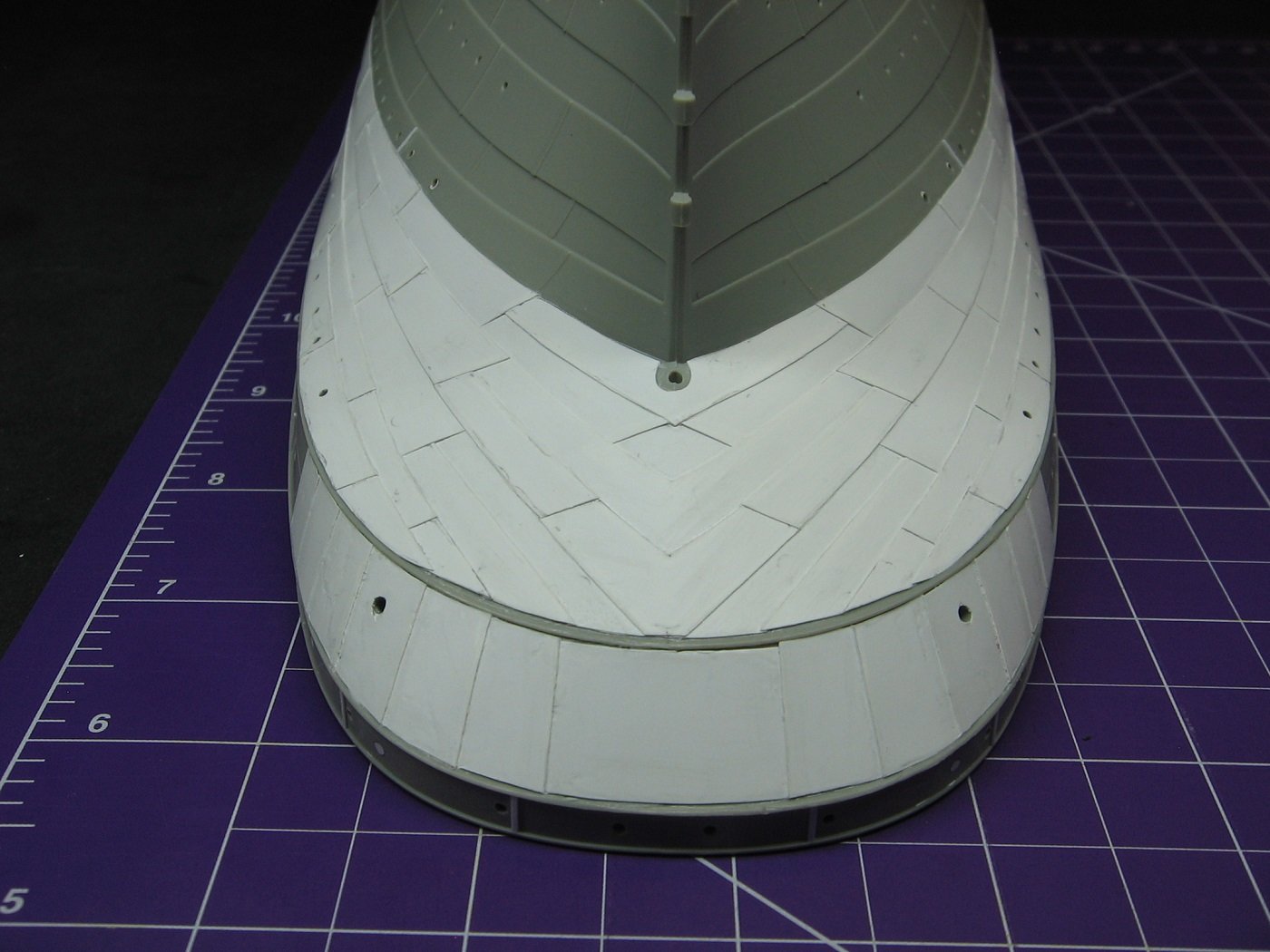
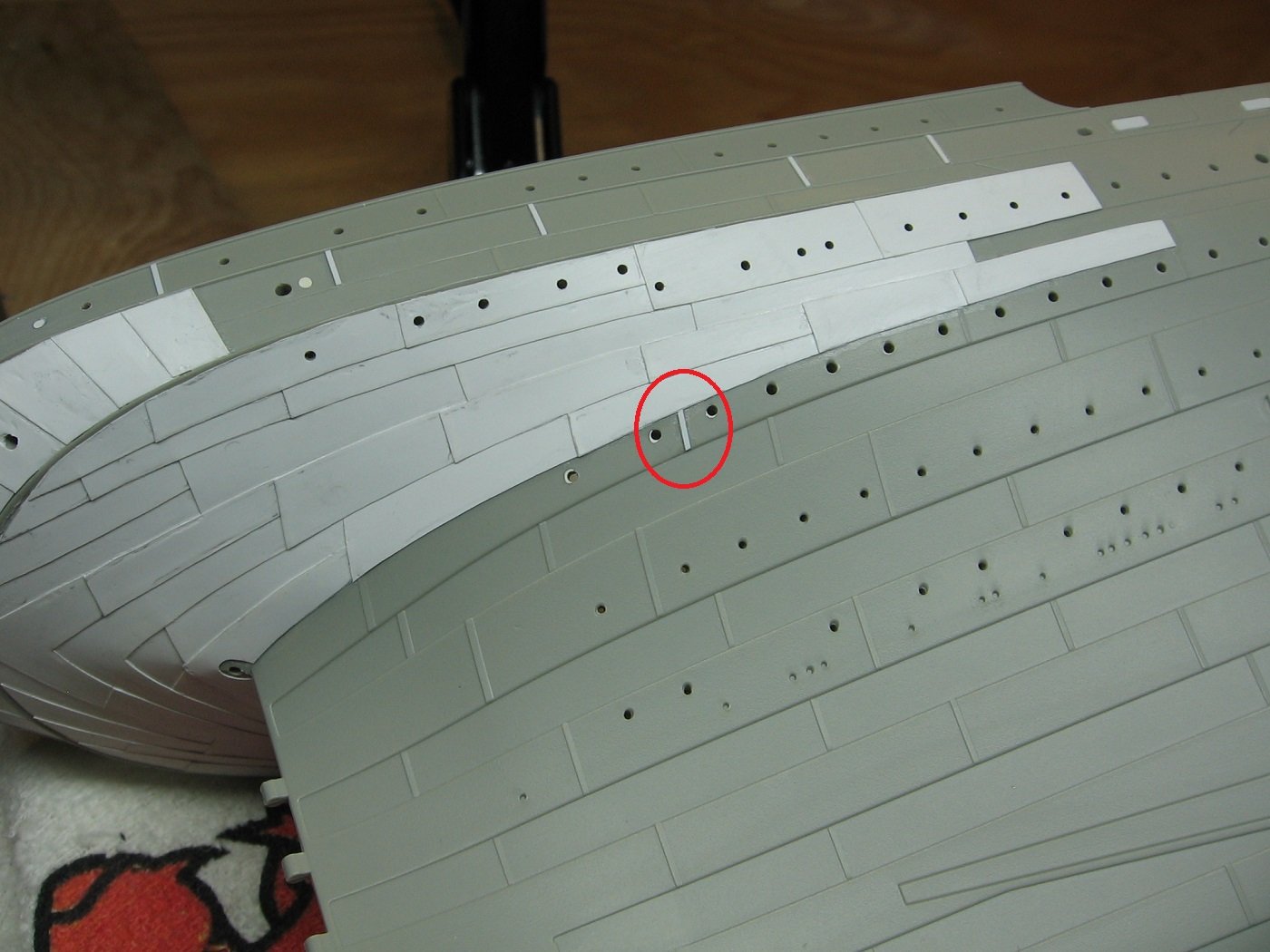
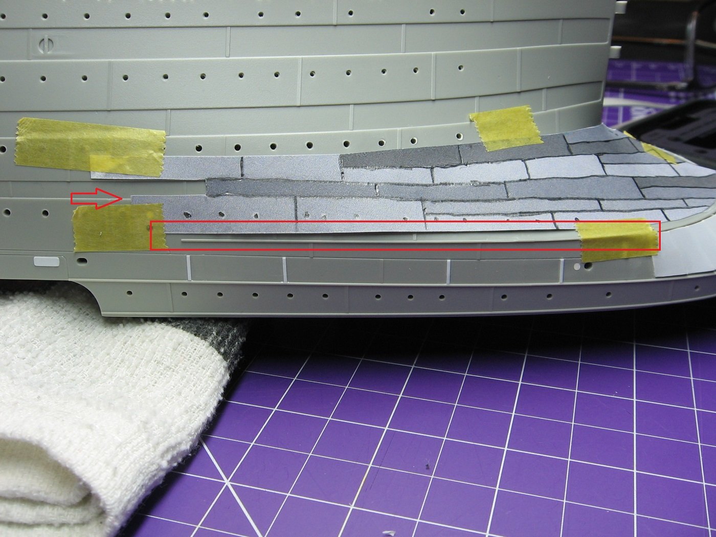
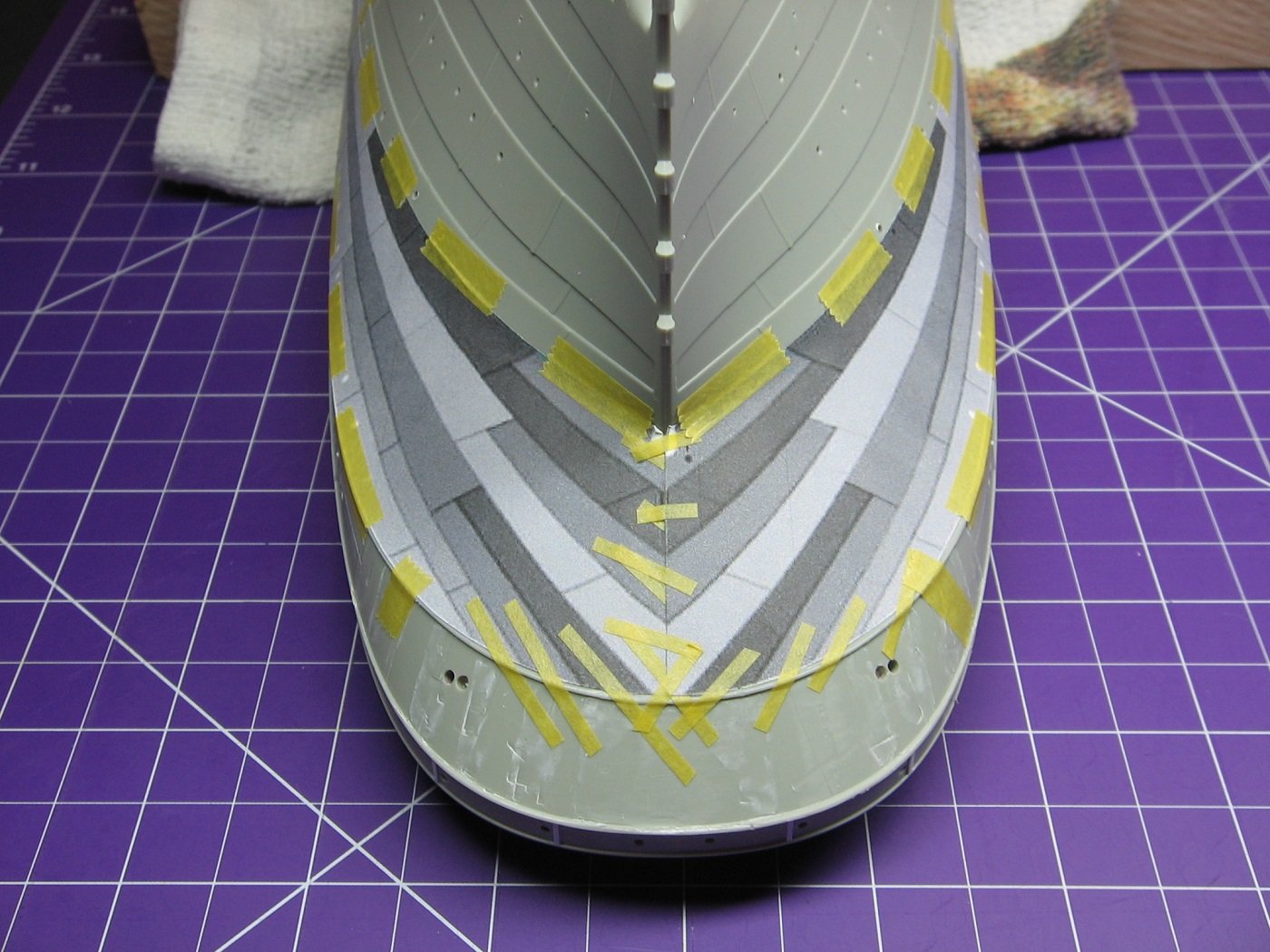
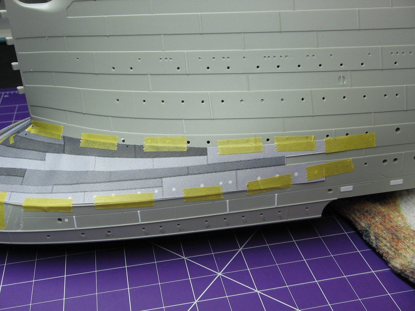
 Returning to the project after a somewhat lengthy and unexpected hiatus. So, last May, Mr. Boyd amended his Hull Corrections document to include some double strakes that are missing on the kit hull. Honestly, my first reaction to this was "Ugh. More corrections. I'm NOT doing them.". But alas, it's winter and I've done them. (Well...not ALL of them. To be explained later). I purchased some 0.25mm x 4.0mm styrene strip for this task. The thickness is very close to bang on (perhaps a wee bit thick), but the width is not. I used a set of calipers to scribe two strips to 3.75mm wide and then trimmed them with a #18 blade. Having said that, I found I still had to trim the width of each strake a tad more just prior to cementing in place. With using strips, I was guaranteed to have one edge perfectly straight. Port Fwd.... I struggled with the Port Fwd section somewhat and had to fill quite a few gaps. I used Milliput Superfine epoxy putty. Port Aft..... Port Aft went quite a bit better.... Starboard Forward.... Starboard side went very well. Just one small gap to fill in the forward section..... Starboard Aft.... More on the yellow and blue circled sections in a bit. Starboard Aft went well also.... Regarding the strake circled in yellow, (both sides, Port and Starboard), two images above.....this is already flush (on the kit mold) and adding a strake here would just create another inaccuracy, in that it would then NOT be flush as reference photographs indicate there are strakes above and below this strake. To make this "flush" would require adding strakes above and below it as well. Therefore, I did not add a strake here. What is missing, however, is a lower panel line here, as indicated.... Panel line added, Port Aft..... Starboard side aft. I used the edge of an erasing shield as a guide for the scriber, (both Port and Starboard)..... And the result.... And finally, regarding the strake circled in blue..... Again....this part of the kit mold is already flush. To add a strake here introduces yet another inaccuracy. For the same reason. Referencing historical photographs shows that there were strakes above and below this strake. To make it accurate would require strakes above and below to be added as well. But that begs the question, where does it end? I have come to the conclusion that the kit hull has LOTS of inaccuracies. How much? 20%? 30%? I have no idea and I'm not about to try and find out. My model is not going to be a museum piece. Myself and my wife are essentially going to be the only ones who see the completed project. And anyone else who does see it will not know in the slightest. Having said that, I still have lots to do to the hull to correct other inaccuracies. I have already committed in my own mind to do so. But chasing the inaccuracies of the double strakes ends here, for me. Thanks for looking. Suggestions are welcome. Cheers, Mark
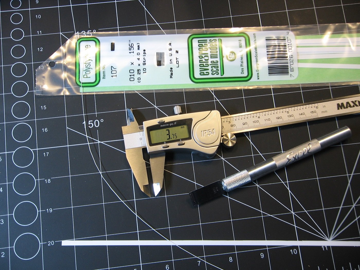
.JPG.671848421c5c3eaa4be3bff7b83602a8.JPG)
.JPG.37b0cabfc47a2b22afd2608c72202bcc.JPG)
.JPG.ec7339e553c8b149a4c8f516cc157c46.JPG)
.JPG.b765ffa907591f1b1d0eb515bd0946b1.JPG)
-
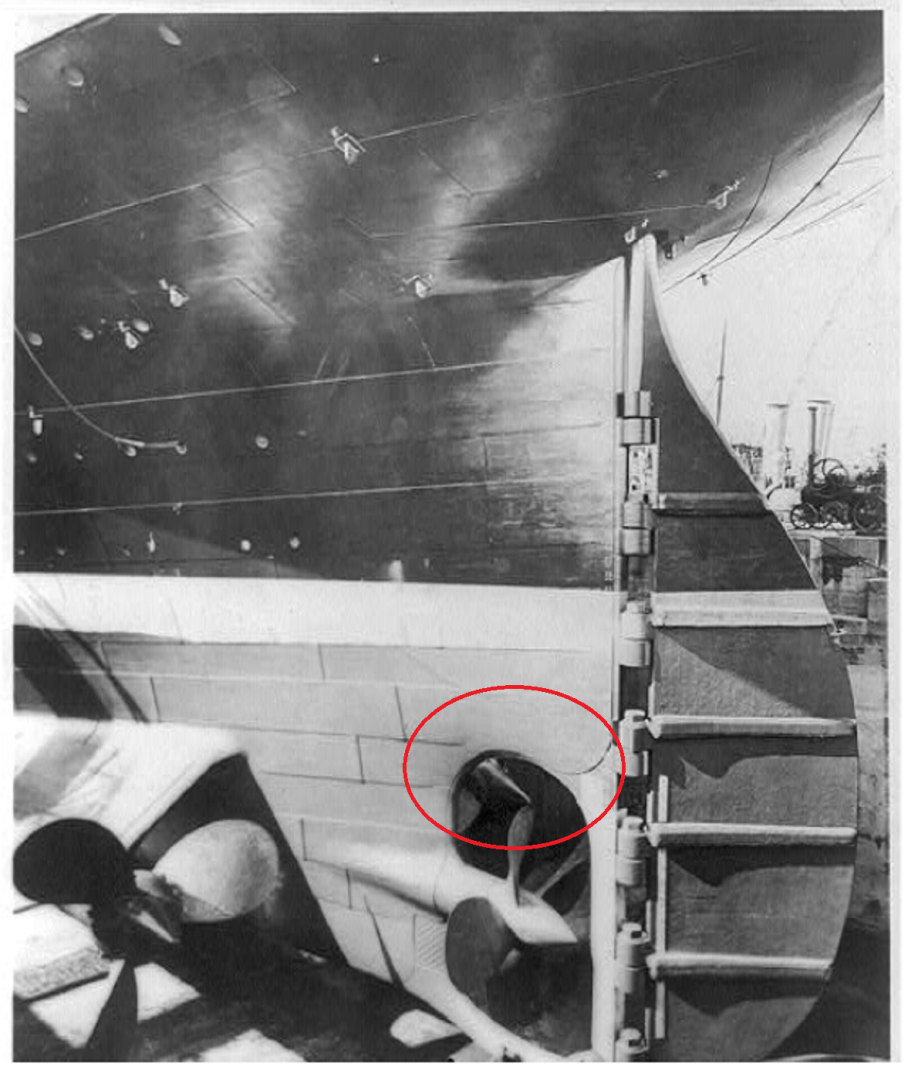
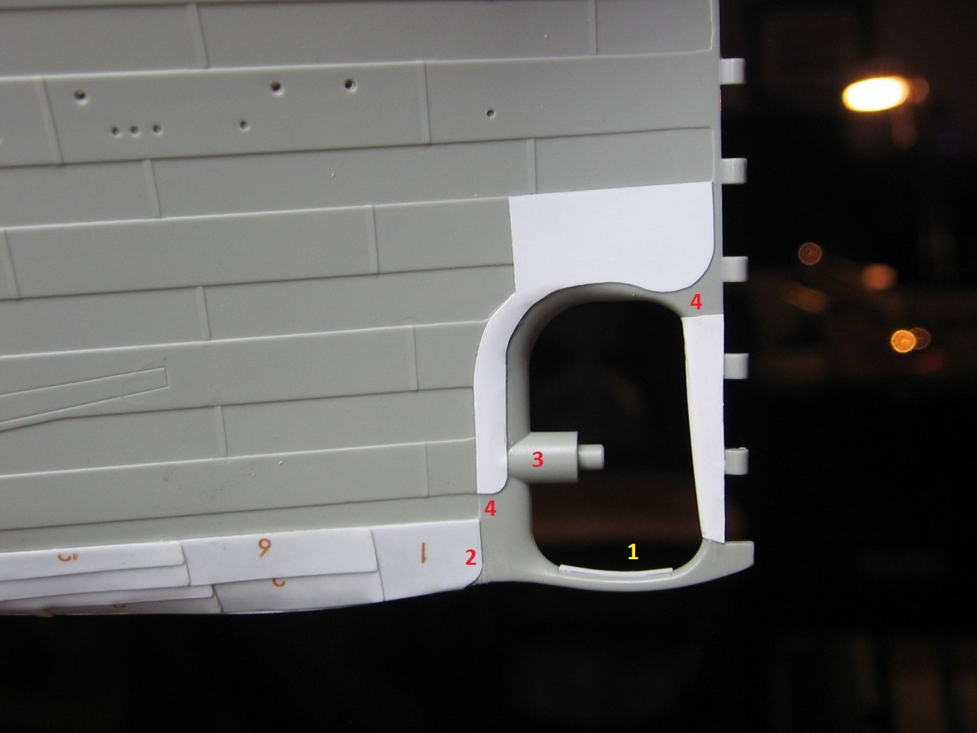
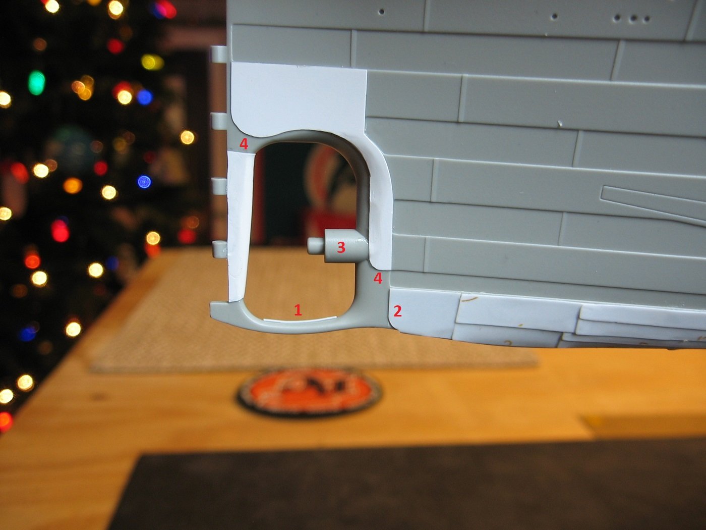
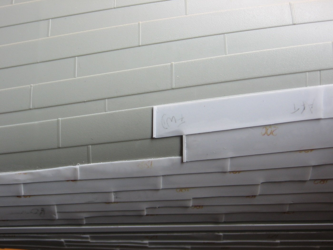
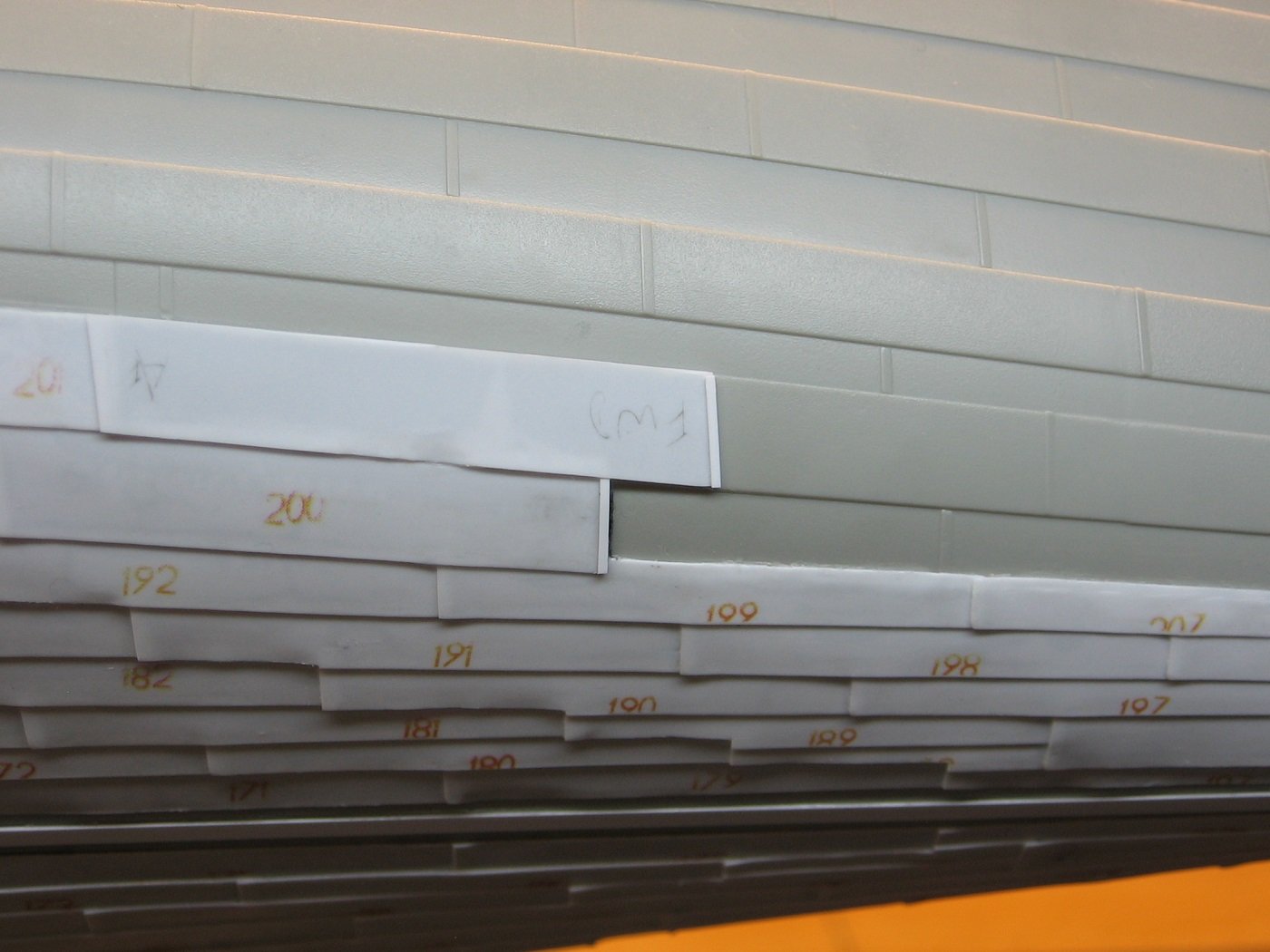
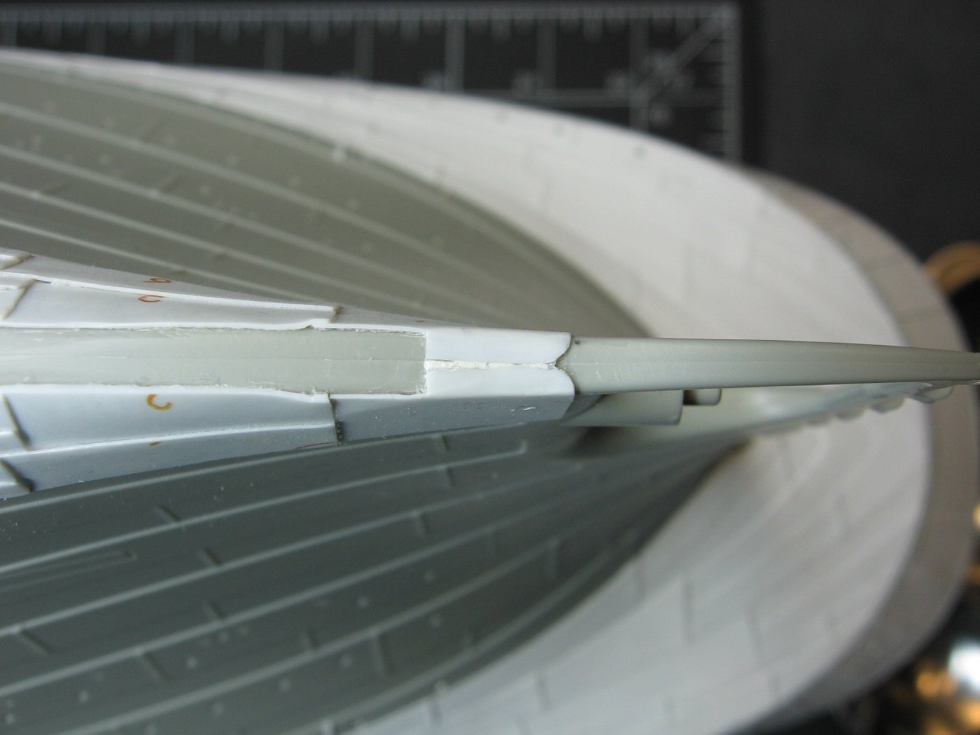
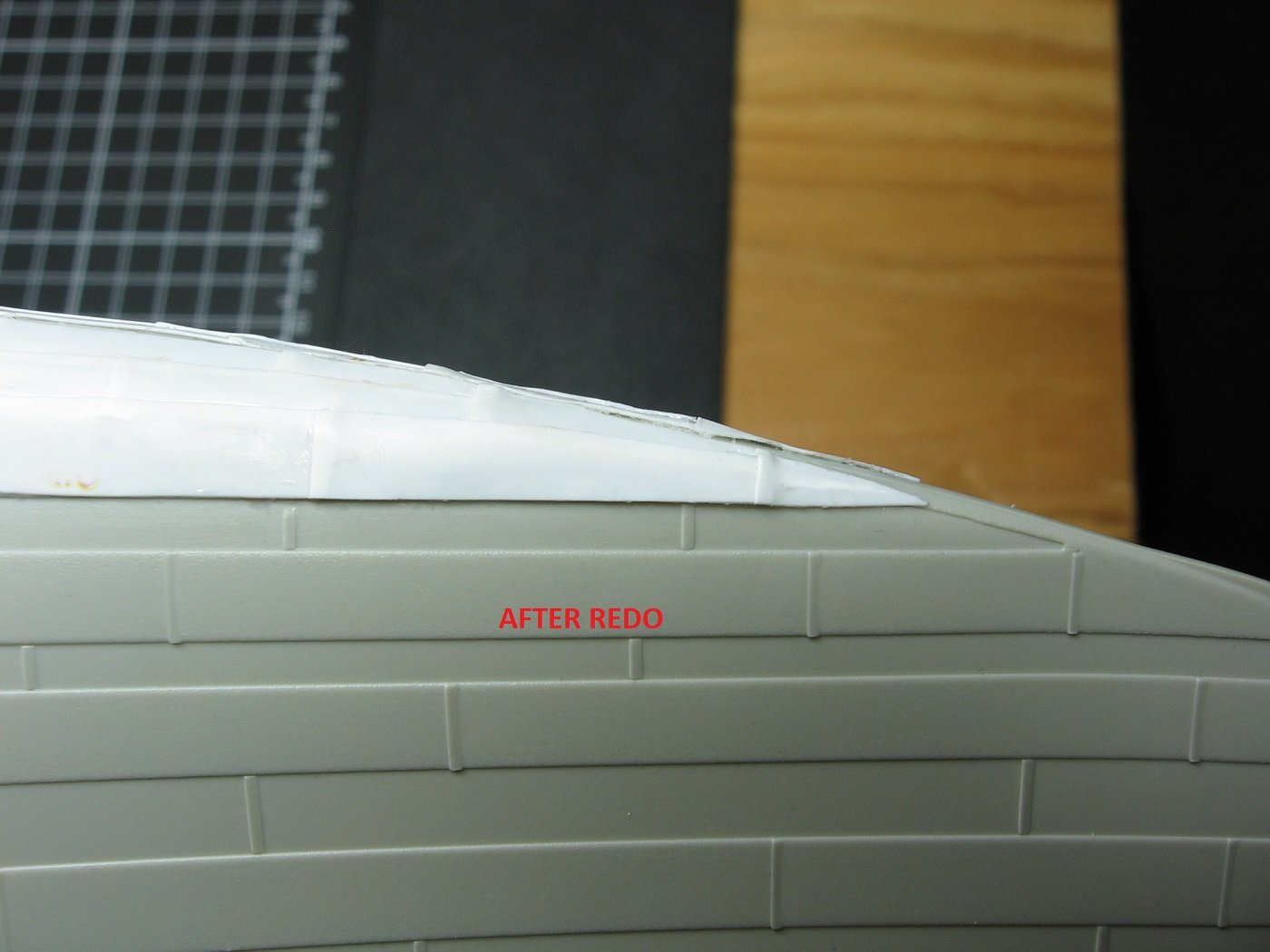
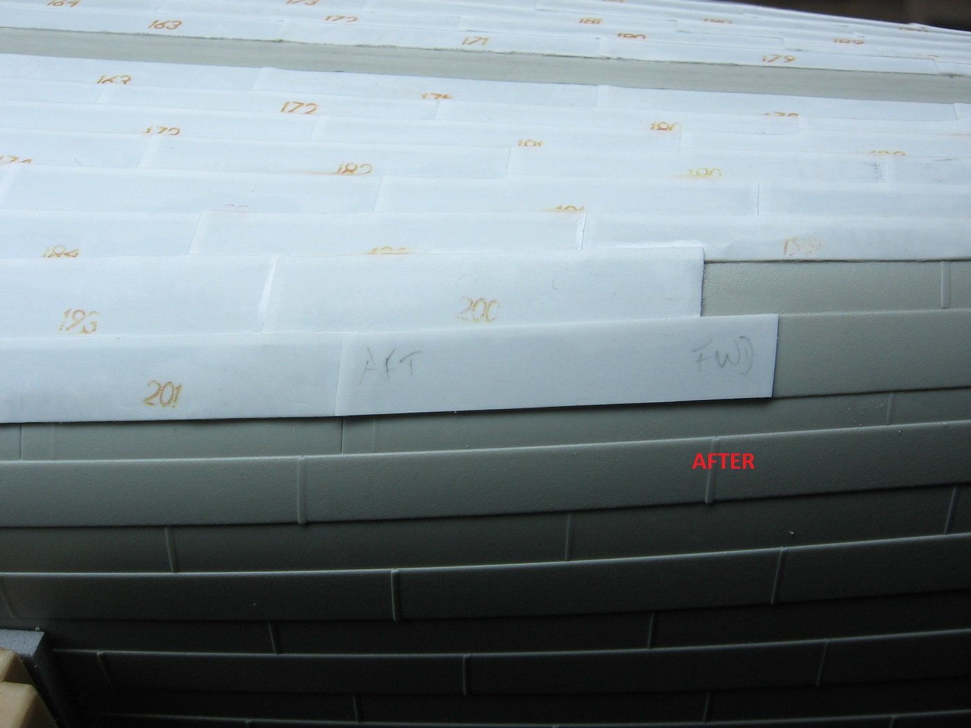
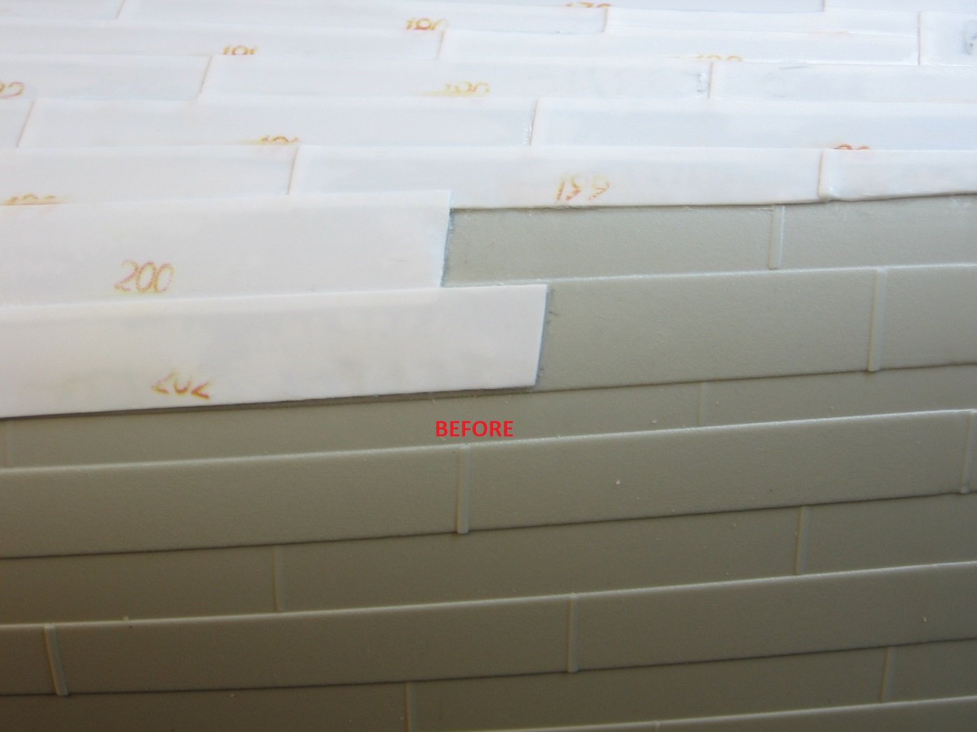
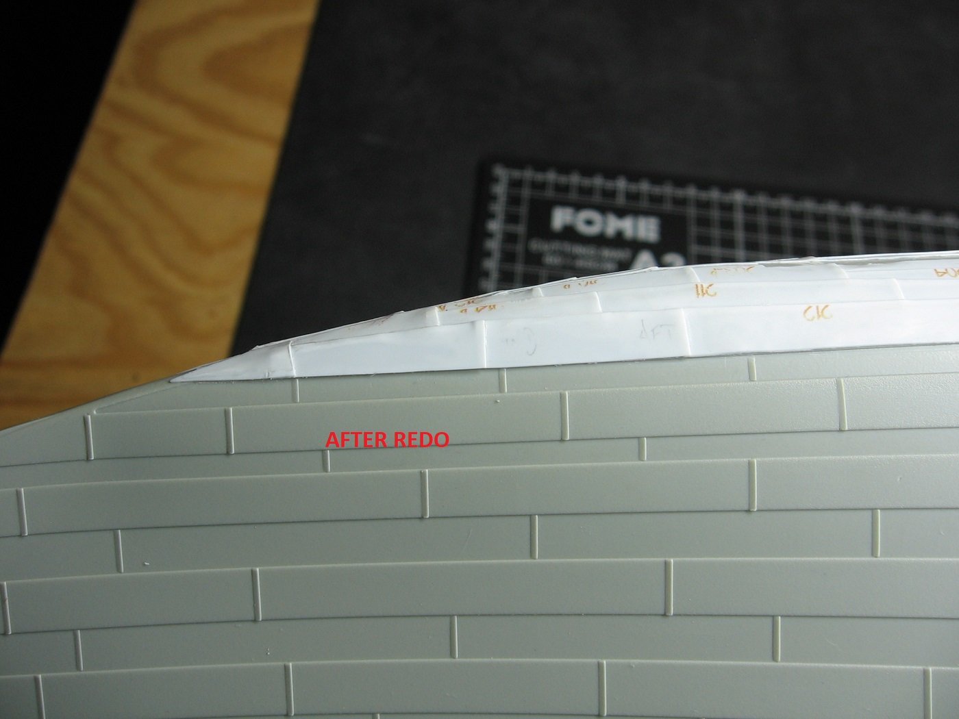
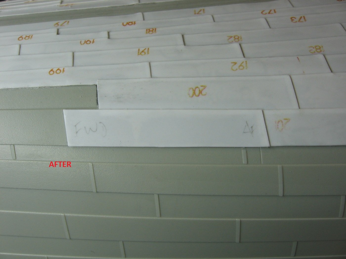
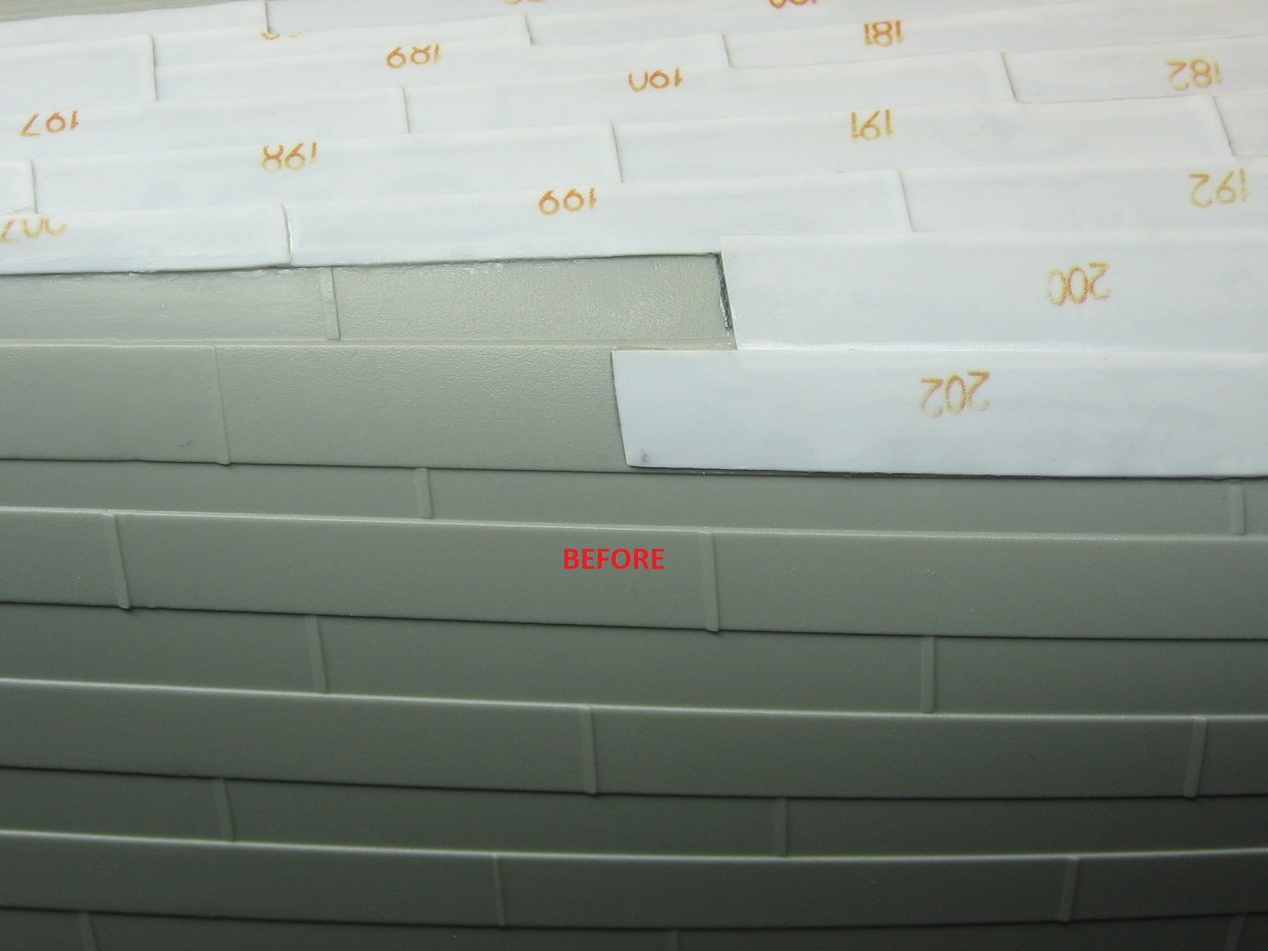
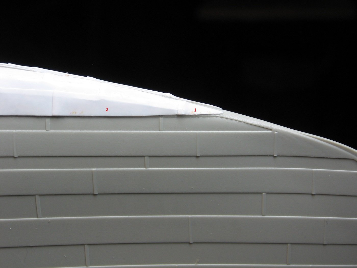
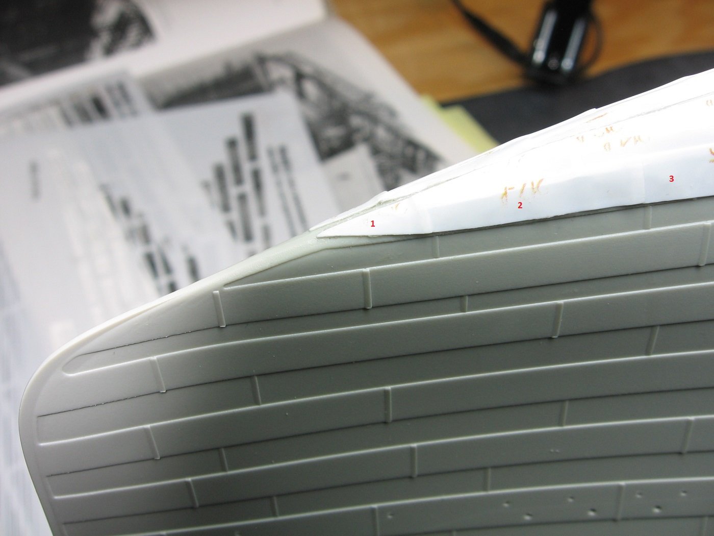
My initial intent with work around the Stern Frame was addressing the kit's lack of the curved lines the plating has in this area, as indicated in this photograph (image obtained from the Library of Congress). But upon beginning this and looking into this further, a few other things came up. First of was the zinc anode sheathing on the Rudder Post. I figured dealing with this was within my skill level. I simply used masking tape and pencil shading to get a measure of the distance around , and also measured the height required (26mm) before removing the tape. And then transferred that to .005” styrene sheeting. Part of the process of cementing this “zinc” anode in place. It took a few clamping/cementing sessions. Then on to my original intent…. First off, I scanned a certain diagram (of the Stern Frame) from a certain publication and then printed it more than once, reducing it each time and matching it to the kit until I got what I thought was the right scale. The original scan reduced to 65% seemed right to me. With some more pencil shading, I got this…. I’m not showing the printed side so as to avoid any copyright infringement. Transferred to .005” styrene sheeting. I applied these pieces primarily with E6000+ glue. After 24 hours I used a rubber band to pull in the edges that didn’t lay flat and finished the job with CA glue. Port Side: Starboard side: 1). “Zinc” anode strip also added here, as per research. 2). Note modifications to Plate #1 of the aftermarket under hull plating kit. Trimmed longitudinally to bring it in line with the kits plate line immediately above, and curvature added as per research. 3). The stern tube for the center prop is just wrong. Still mulling over what to do with this, if anything. Might just leave it as is. It appears to me, upon comparing the mold to historical photographs, that it’s not just the lack of the tapered sheath plating here that is an issue, but I think the diameter of the stern tube itself is too narrow. Next step with this will be deciding which propellor I want to go with and see if the propellor boss diameter matches the stern tube. If the boss is by chance larger, then I’ll look at ways to build up the diameter of the stern tube and continue the modification forward, for the raised plating. Not holding my breath on this one. 4). I have an aftermarket kit that has PE for these locations. And back to the under hull plating one more time…..I came across a build log in a different Forum that made mention of Plates 200 and 202, of the same aftermarket kit that I used, with regard to how these plates just abruptly end and look unfinished. I agree. Therefore, I added .010” x .020” styrene strips to the forward edge of these plates. Port: Starboard: Thanks for looking. Suggestions are welcome. Cheers, Mark
.JPG.dec2a83f68d47b30a4d9a1d19d557145.JPG)
.JPG.1b6d9fc1a76a9bea0707fd9b78e53b85.JPG)
.JPG.2d99efb2a410bce1ebcc5811e42a6aa0.JPG)
.JPG.c94b7f45967e0df5f42188d8a6b5e843.JPG)
.JPG.56693081cb6e10b96add9d6e74e64ea1.JPG)
.JPG.78140d7f4d1f1ebc23eb7fa51518eeb0.JPG)
.JPG.9a33173792f1a9f61073f612fdfc4d9a.JPG)
.JPG.18be9aecda39273628d26faecff57a0c.JPG)
-
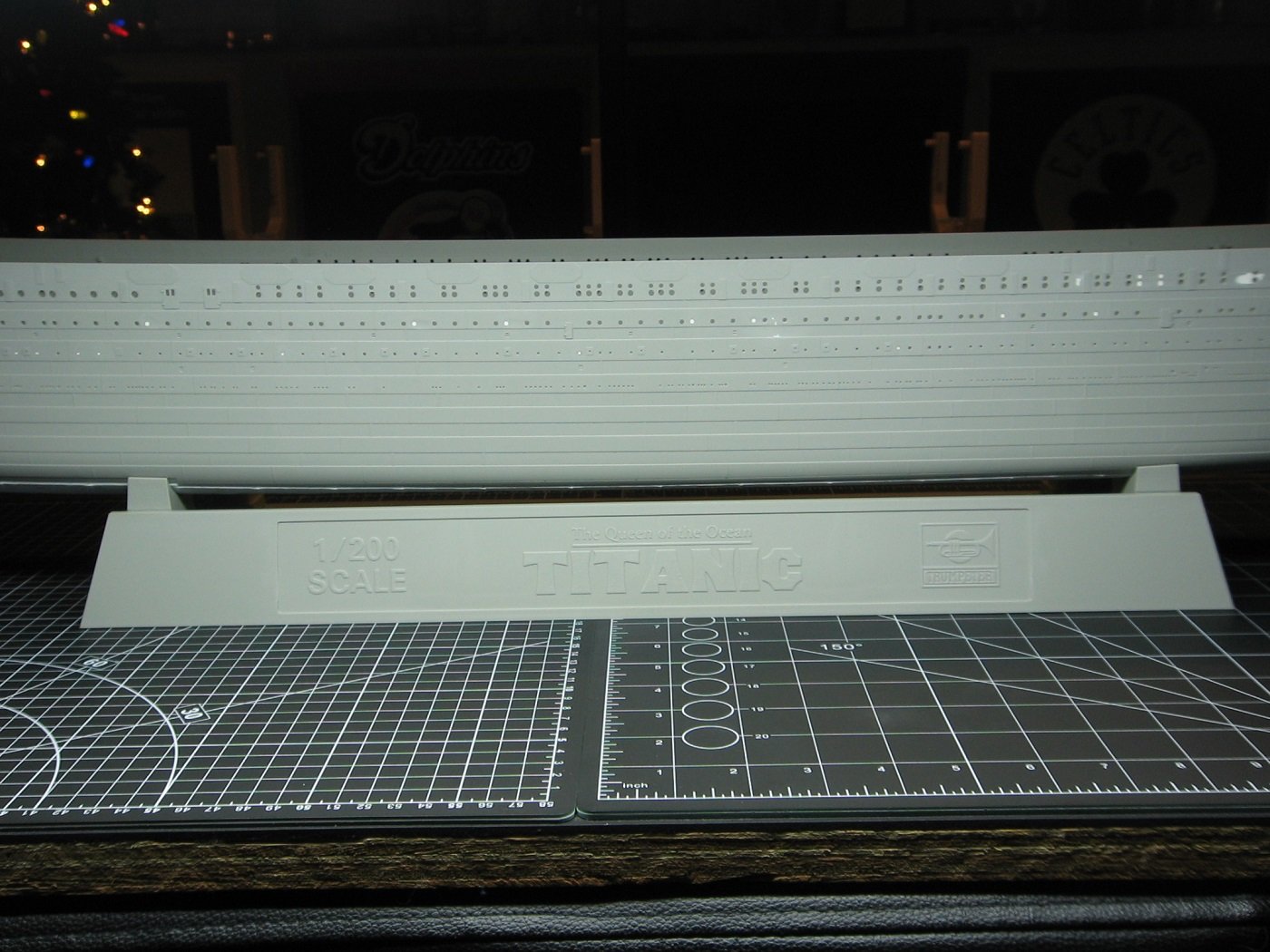
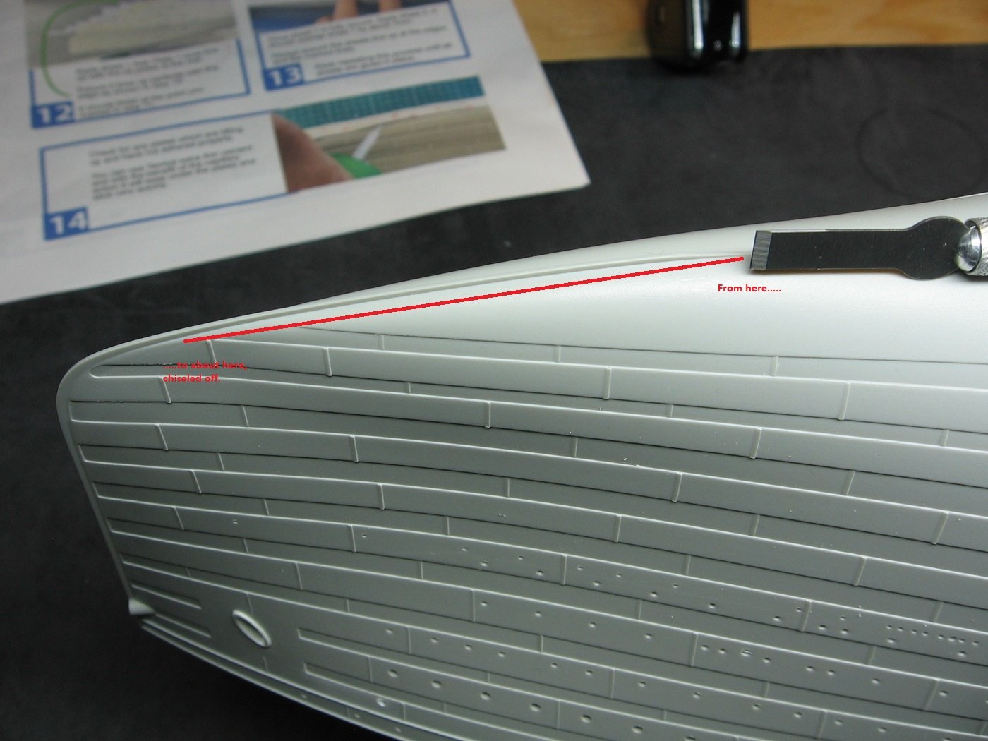
Change of mind. Decided to do the few other things first and the Keel Bar last. So, during the dry fits it appeared to me that the “steel” casting leading up from the Keel to the Stem was in the way of Sheet 5. So, I knee jerk reacted and chiseled a portion of it off. This was weeks ago. Since doing that, I was concerned that perhaps I was wrong and shouldn’t have. However, upon applying Sheet 5 it was confirmed that it was in fact in the way. In hindsight, if I did make a mistake with this, it would be that I chiseled off too much. OR,….perhaps I should have left well enough alone and modified the plates of Sheet 5 instead. Regardless, it is what it is and it needed fixing. I used .75mm x 1.0mm (.030” x .040”) styrene rod to replace what I removed. .75mm is the transverse measurement, 1.0mm is the vertical. There were some gaps between the plates and this new casting that needed filling. I used Vallejo Plastic Putty 70.401 for that. I also used Vallejo Plastic Putty 70.401 to clean up the mess where the two #1 plates meet at the Stern. The Keel Bar in place. As mentioned earlier, I used 0.38mm x 2.5mm (.015” x .100”) styrene strips for that. And finally, will the hull still fit in the kit provided stand with this aftermarket kit applied? Yes. It will. And that’s that. As long as it took, I’m really happy with how this aftermarket kit turned out and I’m really looking forward to seeing what it will look like with paint on it. (Much better, I expect.) Having said that, I can’t give it 5 stars out of 5. I think the instructions could have been a little more comprehensive. - In particular, regarding EXACTLY where should the #1 plates on Sheet 1 start on the longitudinal axis, when applying those sheets to the hull. Kind of important. Thankfully, I made it work with three dry fits. - A bit of a heads up on what to expect with the application of Sheet 5 would have gone a long way too. - And finally, both #202 plates were clearly not cut wide enough. Up next, I’m going to look at doing some scratch plating above the Stern Frame. Thanks for looking. Suggestions are welcome. Cheers, Mark

-
Thanks, Alan. It has taken me quite a bit longer than I originally envisioned. Looking forward to completing this aspect of the build and moving on to the next. Oh, and Santa usually comes through with a bottle or two. I have no concerns with that. Cheers, Mark
-
Foremost plates of Sheet 5, both sides, redone. Port side. Starboard side. More misalignments….. Plate #1, Starboard….. ….and redone. I must say the following two “misalignments” (for lack of a better word in this case), in the vicinity of Frame 90F, are not the modeler, but rather, the aftermarket kit. The pictures clearly show Plate #202, on each side, are not wide enough. They come pre-cut. They should be wide enough. Port Side. Starboard side. Next up, I’ll be installing the Keel Bar. I will not be using the supplied aftermarket keel strips for two reasons. 1. Four of the seven strips provided are distorted. 2. They are not to scale. (Perhaps a moot point, but given reason #1, might as well model the Keel Bar to scale). Titanic had a Keel Bar (flat bar strip for protecting the keel) that measured 19½” wide x 3” thick. At 1/200 scale this is 2.48mm wide x 0.38mm thick. The kit provided strips are 2.0mm wide (1.5mm at some points due to the distortion) x 0.20mm thick. I’ll be using 2.5mm x 0.38mm styrene strips for the Keel Bar. Just a few things left to do after that. Thanks for looking. Suggestions are welcome. Cheers, Mark
.JPG.c1185abcae7d1c7025afbf6fe2f6a233.JPG)
-
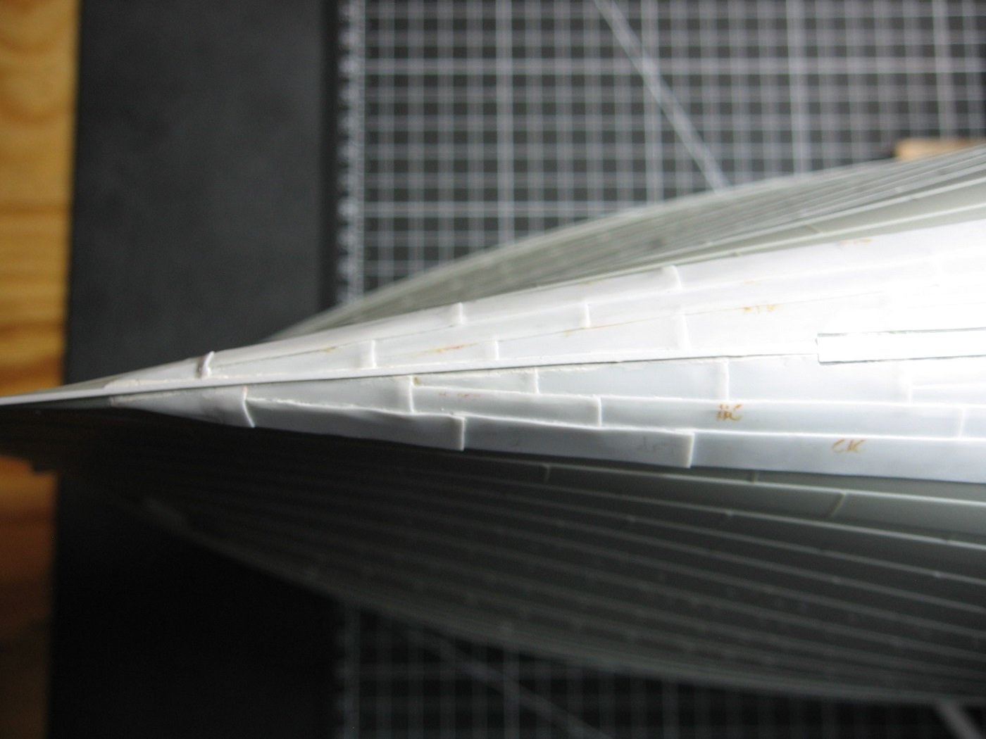
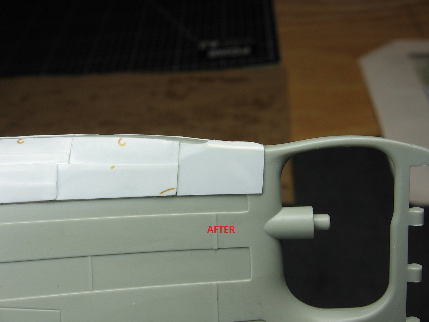
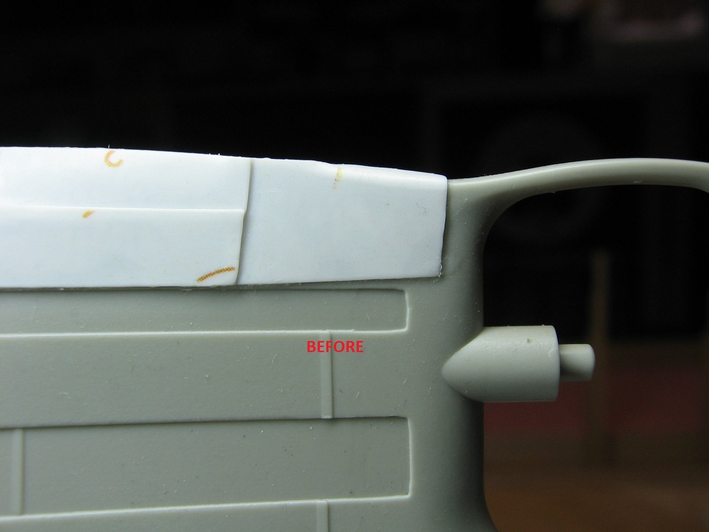
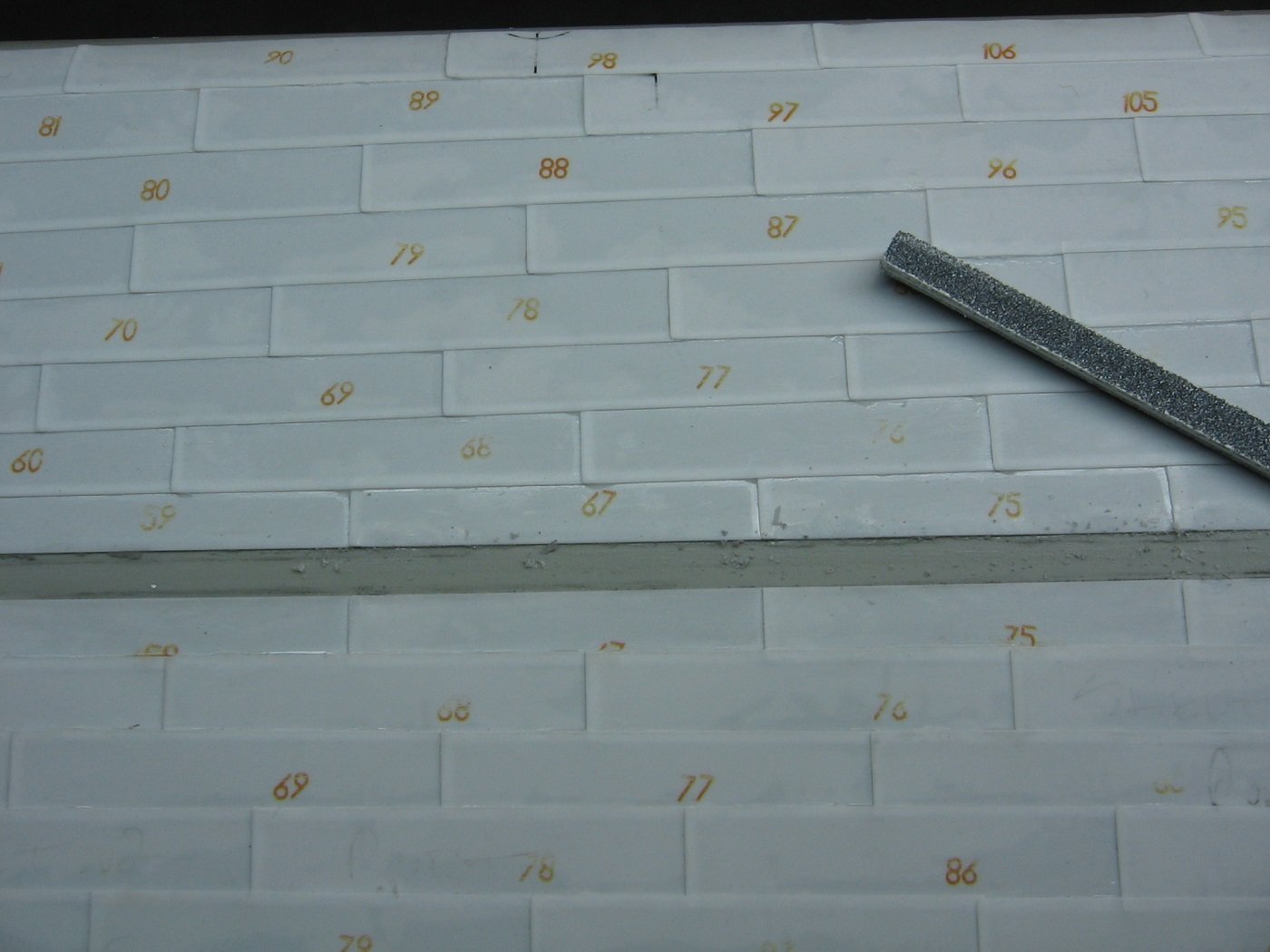
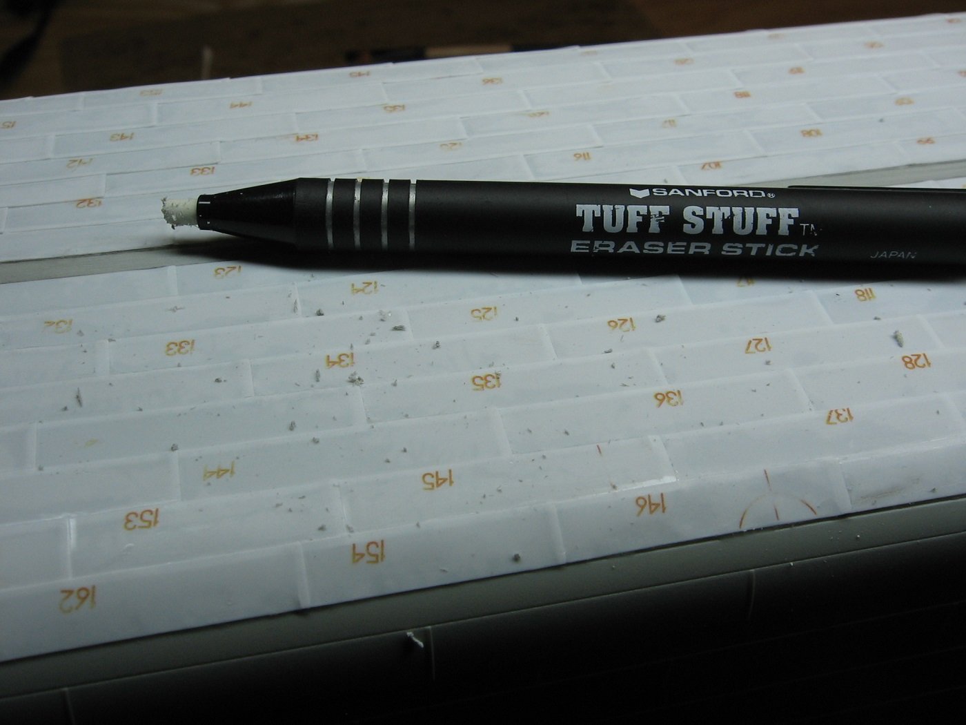
Getting back at it after basically one week away from the model bench due to a lot going on. All sheets are now affixed to the hull. Began prepping for laying the Keel Bar by giving the Keel Line a sanding. Before continuing with the Keel Bar itself, I decided to clean up the entire job. The texture of the E6000+ glue is similar to silicone, when dried. I found an eraser stick very useful for cleaning up excess E6000+. For excess CA glue, I used a 17a chisel blade, very delicately. After completing the clean up, I decided I was not happy with some plate misalignments along the Keel Line. Therefore, I used masking tape to provide a straight edge, and chiseled them clean. In the meantime, I was pondering how to deal with some misalignments of both sides of Sheet 5 at the bow. Port side. Starboard side. Option 1: Leave it as is. Option 2: Sand down the kit lines. (This just seems wrong.) Option 3: Remove and replace. I’ve chosen option 3. I’ll be removing the existing plates, as numbered in the pictures, and using new plates cut from the leftover scrap styrene sheets. Footnote: I can’t explain all these misalignments. I thought I was quite precise with building the plate sheets on the templates. Can’t figure if it’s me, or the manufactured product? Or perhaps a combination of a bit of both? Anyhoo…. Thanks for looking. Suggestions are welcome. Cheers, Mark
.JPG.30000f6b1a27cf7767620649293da773.JPG)
.JPG.631b779bb2d8de9af82ed3071d319b1f.JPG)
.JPG.c04b48591db3e7ec2cb875bb015f4760.JPG)
.JPG.df4709c2c44285f0a59066e9ac4fd3a2.JPG)
.JPG.976830daa1dbf50798307560a1c5eccb.JPG)
-
Thank you. I am only one year in as a scale modeler, so to receive such a compliment means a lot. Cheers, Mark
-
Progress Report. Sheet 5, Port side. I found it necessary to robustly tape this sheet down. No shifting occurred. There was significant overlap here, of the aftermarket kit overlapping the kit’s plate line. I sanded down the overlap and this is the result. Hard to tell in this picture but it is much better. Again, hard to tell in the picture, but there is unexplained misalignment here. I’ve marked with a pencil what needs to be trimmed. And this is the result. I know, hard to see in the pic and it is not "historically accurate", but it is definitely cleaner and better. Some further trimming was required here, so I used masking tape for a straight edge. Trimmed using a 17a chisel. And on to the final sheet. #5 Starboard side. I must say that Sheet 5 on the Port side has been the most difficult and time consuming, so far. I'm expecting the same with the Starboard side, as there looks to be some unexplained misalignments with this sheet as well. Thanks for looking. Suggestions are welcome. Cheers, Mark
.JPG.438936bdc335826d567e347a6b6a8c7d.JPG)
.JPG.0c75c7c4c737a9a40df6fbed18901764.JPG)
.JPG.97a4a5a3e30e2406eba88f9c297ad0d9.JPG)
.JPG.0d907687ea2caaf458990ab56f20fc06.JPG)
.JPG.85575052dedcdd857130c7ea230b5805.JPG)
.JPG.c89ca9e4a422ca50b448aec918fb3ad6.JPG)
.JPG.3f0a4bac33c2a3218827f14a47486853.JPG)
.JPG.bcd8721021fc19845907afbcec3d8bc0.JPG)
-
Progress report. Trial and error learning curve while continuing the under hull plating application. I was finding applying CA glue to the edge gaps tedious and time consuming. So, in order to assist the E6000+ glue with doing its job, in particular....the outer edges along the Turn of the Bilge, I changed my taping strategy. However, I found taping the outer edge of Port Sheet 2, as shown, didn’t work so well. It was not enough tape, and lifted. CA glue was still required. So, for Starboard Sheet 2, I beefed up the taping on the outer edge, transversely. However, the edge here lifted somewhat as well. Not only that, but applying the transverse tape strips actually pulled the whole sheet outward and away from the keel. Unfortunately, I thought it was fine and walked away from it. The inboard edge, here, should be up to that pencil line. Misalignment shown here as well. For Port Sheet 3, I was still optimistic that I could tape the outer edge down, and save a lot of CA gluing time. So, I beefed up the transverse taping on this sheet even more (no pic). However, doing that pulled this sheet outward by a lot. Fortunately, I noticed it this time (hard not to) and the curing time of the E6000+ allowed me to remove all the tape, and lift and reposition the sheet. I re-taped the sheet without taping down the outer edge. Just left it as is, as shown, and then just walked away, letting the E600+ glue do its thing. Starboard Sheet 3 taped as shown. Outer edge left unsecured. Letting the E6000+ cure. Next day (allowing at least 12 hours to cure)….taping the outer edge in preparation for CA gluing. CA gluing is inevitable. In my experience, there are no shortcuts with this. It is what it is. Applying CA glue, pushing the plate down to the hull and allowing capillary action to do its thing. Next step, remove the transverse tape strips and CA glue there, where the plate overlaps are. In my experience, there are more edge gaps than just the outer edges that require CA glue. For these six larger sheets, it’s taking me about 3 hours each sheet to apply CA glue and get the edges and gaps secured. Thanks for looking. Suggestions are welcome. Cheers, Mark
-
Did a complete dry fit of the Starboard side and pencil marked the hull for fit, accordingly. Sheet 1 for the Starboard side applied last night. Ended up with a slight misalignment with Plate #1 (indicated within the red circle). Not sure why that is as the rest of the sheet is aligned properly. I haven't completely researched the Stern Frame plating yet, but I'm hoping I'll be able to "fix" this when I get to that. The blue circle indicates plate edges protruding below the keel that I intend to sand down. I found this sheet a bit more of a challenge than the first Port sheet, in regard to getting the fit right as well as applying CA glue to the large gaps. Seems odd as I had 2 -4 glasses of wine in me for the first sheet. Perhaps different ergonomics that come with working on the opposite side is the explanation. But I digress. Thanks for looking. Suggestions are welcome. Cheers, Mark
-
Yves and Evan, I still consider myself a rookie model builder, so thank you for the words of encouragement. It's means a lot. Yves, Interesting suggestion re: aluminum tape. It would be more malleable. Evan, When I did a Google search to find an answer to my above question(s) this very build log came up as one of the search results. Needless to say, I was quite pleased with that. So, yes....absolutely I hope that my documentation here will be of benefit to others who choose this aftermarket kit. Regarding sanding of the prominent plate overlaps, thank you for that suggestion. I will consider it, however, I'm not sure my skill level won't botch it. Some sanding I am very much considering is the plate edges in the after part of Sheets 1 (both sides) as there are quite obvious protrusions below the keel. Cheers, Mark
-
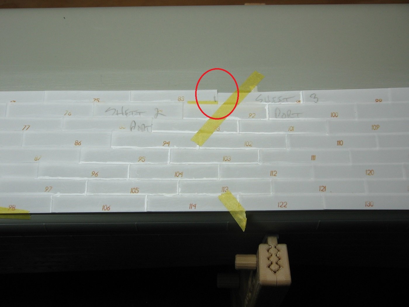
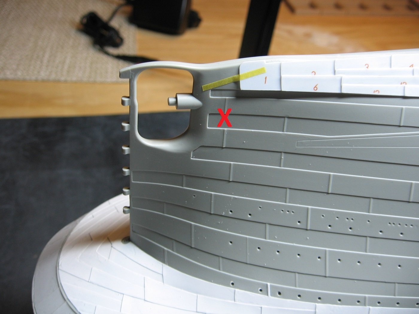
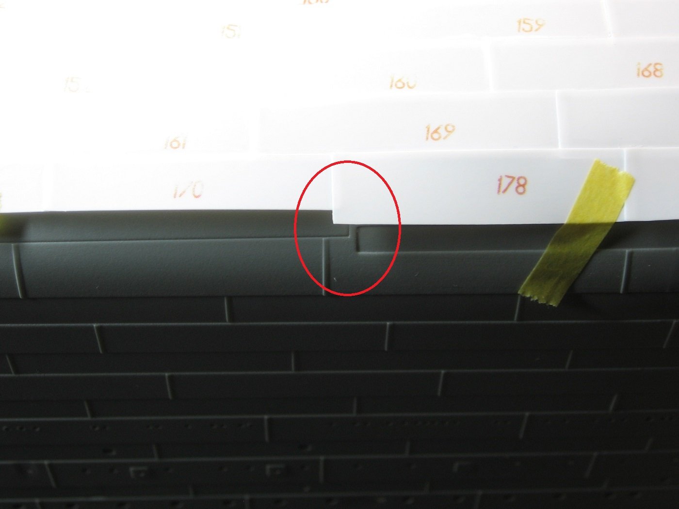
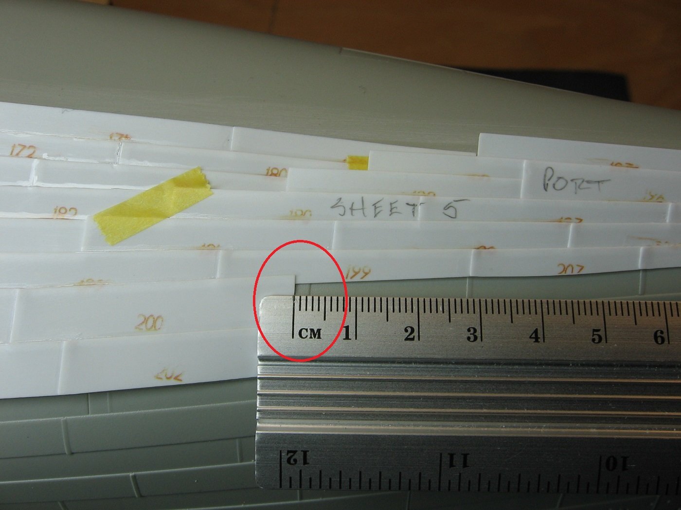
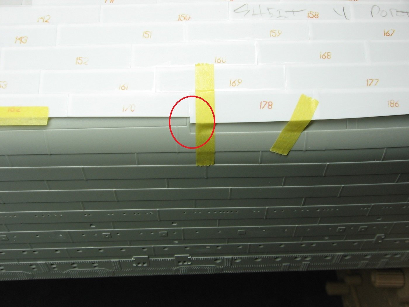
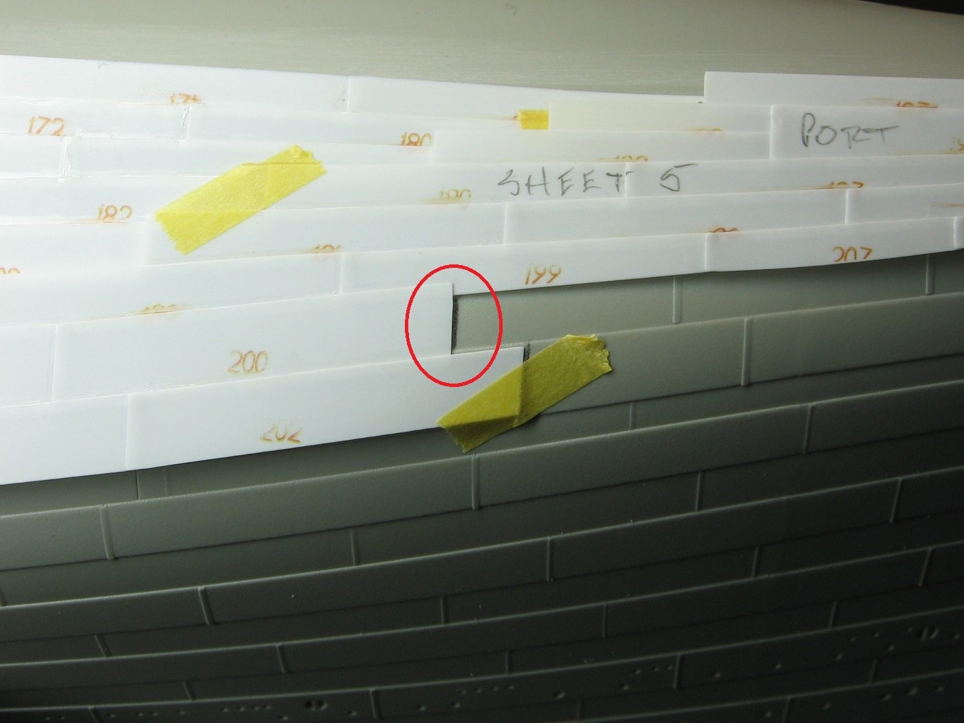
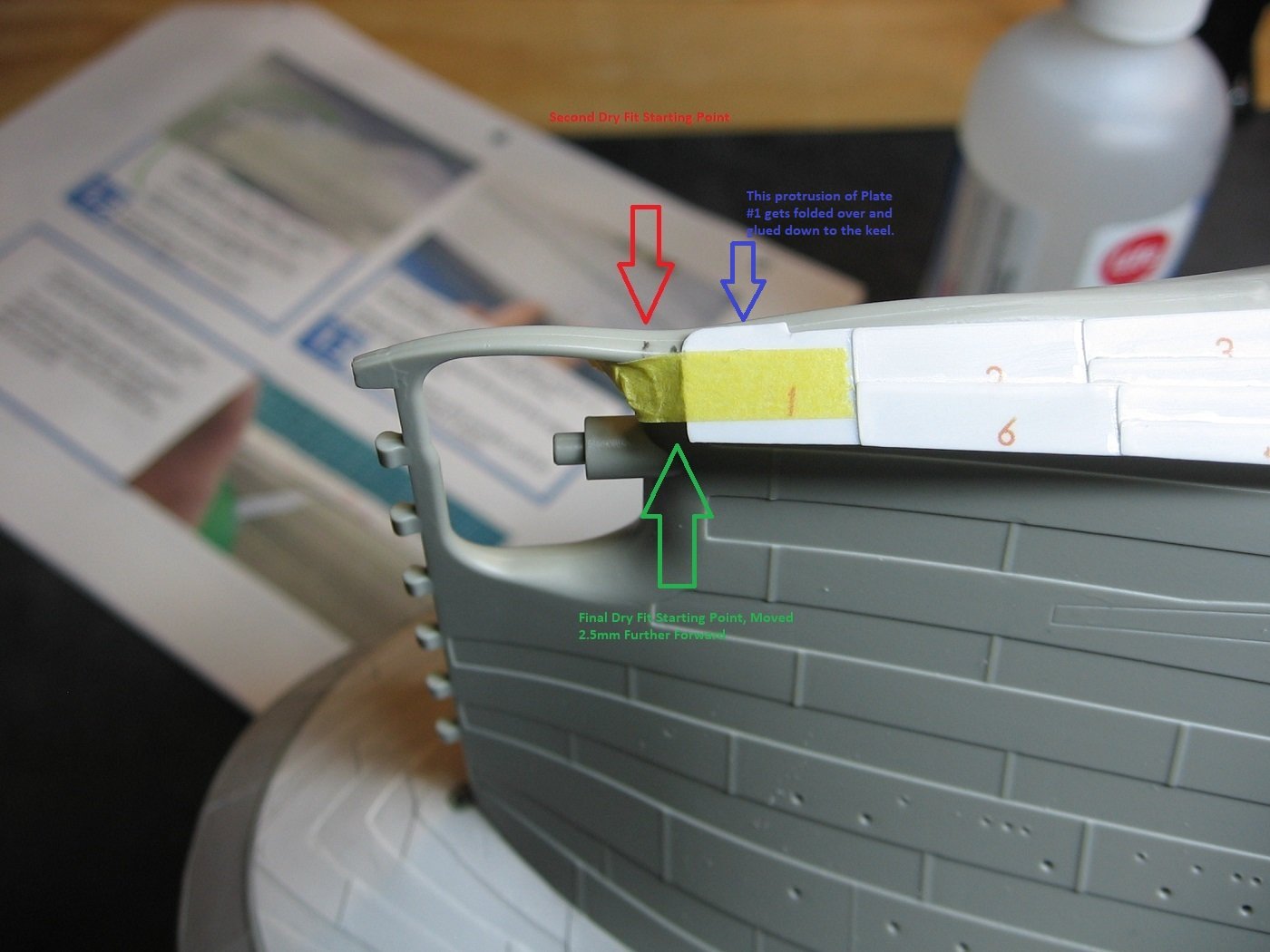
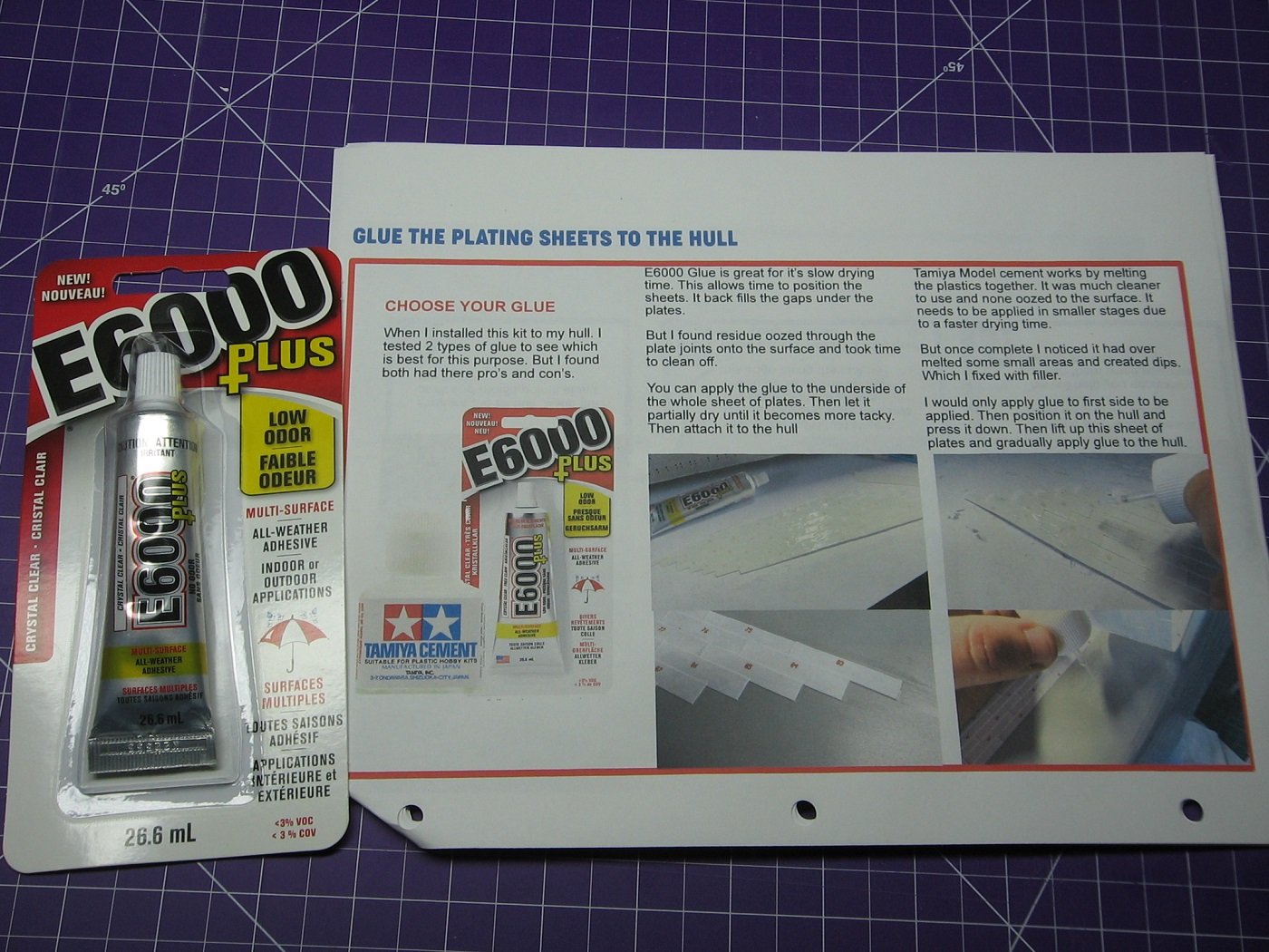
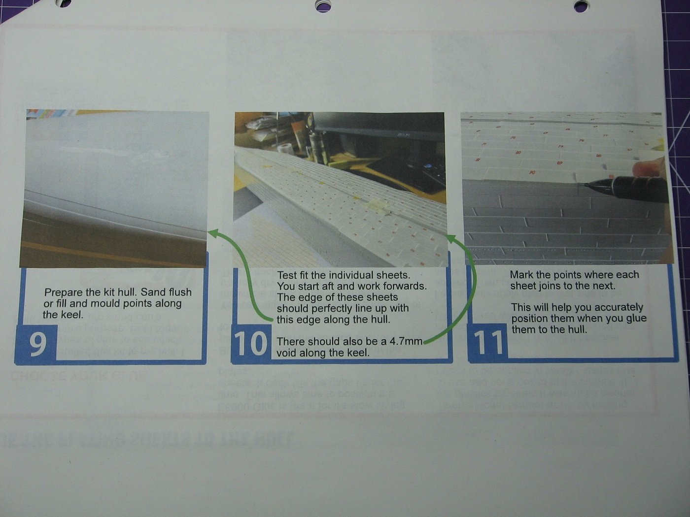
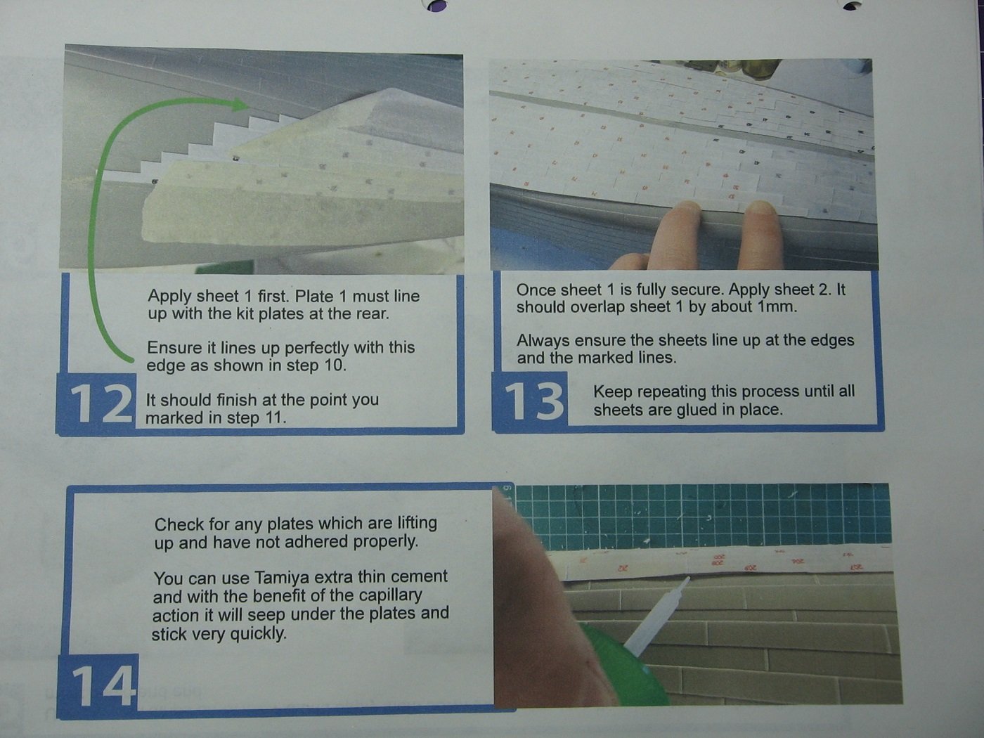
Sheet 5 done. Time to begin attaching the sheets to the hull. Instructions for doing so.... The instructions are quite clear and specific regarding the fit of the sheets transversely. However, they are not clear and specific regarding where to start with Sheet 1 longitudinally. “Plate 1 must line up with the kit plates at the rear.” It is unclear what, exactly, that means. Dry Fit #1 This is where I started with Sheet 1, Port Side, taking into account the vertical width of Plate #1. This positioning ended up being wrong. Marking for the 1mm overlap for Sheet 2. Port Sheet 1 dry fit, showing transverse alignment. Port Sheet 2 dry fit, showing transverse alignment. Port Sheet 3 dry fit, showing transverse alignment. Port Sheets 2 and 3 dry fit, showing transverse misalignment inboard. Something isn’t right. I continued the first dry fit with Sheets 4 and 5, but neglected to take pictures of this. The overlap of Sheet 5 onto Sheet 4 was way too much. From memory it appeared to me to be ~10+mm overlap, rather than 1mm. Something was clearly not right. It was quite obvious that everything needed to be shifted aft. But how far aft? Where is Sheet 1 supposed to start? Off to YouTube to research an answer. Dry Fit #2 – I found little information on YouTube regarding this aftermarket kit, and nothing that specifically addressed my question. However, in one video there where a few seconds that appeared to show the aft edge of Plate #1 of Sheet #1 as far aft as the stern frame. This was my starting point for the second dry fit. Unfortunately, I neglected to take a picture of this as well. However, this starting point is indicated in an upcoming third dry fit photo. The following two pictures show longitudinal misalignment still present. Everything now needs to be shifted forward. The middle of Sheet 4. The step from Plate 170 to Plate 178 is supposed to align with the kit plates. This isn’t mentioned in the instructions, but it’s obvious. Longitudinal misalignment of Sheet 5 indicated here. Again, proper longitudinal alignment isn’t mentioned in the instructions regarding this sheet either, but it’s obvious. By measurement, everything needs to be shifted 2.5mm forward. Dry Fit #3 Sheet 1 moved 2.5mm forward. Red arrow indicates the pencil mark showing the starting point of the second dry fitting. Sheet 4 aligned longitudinally. Sheet 5 aligned longitudinally. As well, the inboard misalignment mentioned earlier, of Sheet 2 with Sheet 3, is no longer there. Okay. Appears I got it. Time to glue. I chose to go with the E6000+ option. In another YouTube video, the modeler used a Q-Tip to spread the glue on the underside of the sheets. I did the same, but I would not recommend that method as the cotton spreads out from the tip and, at one point, a chunk of cotton came off. For the subsequent sheets, I plan on using a cheap bristle brush. I managed to spread the glue thin enough to avoid the potential issue of glue coming up through gaps at the plate seams. Dealing with large gaps along the Turn of the Bilge…… At first I attempted using Tamiya Extra Thin Cement to deal with the large gaps, as per instructions, however, as one has to hold pressure on the styrene during the curing, it became quickly apparent that doing all gaps by this method was going to take way too long as the curing time is relatively slow. Therefore, I switched to CA glue and applied it with a Glue Looper. Another aspect I learned from one of the YouTube videos is that the protrusion of Plate #1 is actually to be folded over and glued down to the keel. This is not indicated in the instructions. I'm still undecided on the position of the aft edge of Plate #1. I may choose to trim that when I tackle the plating work around the Stern Frame. Port Sheet 1 completed. I figure it would be best to do Starboard side Sheet 1 next, as opposed to the rest of the Port side. In my mind that approach would ensure uniform alignment of both sides on the longitudinal axis. Thanks for looking. Suggestions are welcome. Cheers, Mark
.JPG.d2872364142b58d621b0fdbc048b7fba.JPG)
.JPG.3390200615061d84e9bc0337e0a0fb3f.JPG)
.JPG.6b5d57574d567ac0aedecfb209dcc468.JPG)
.JPG.3d46cf23b940eca649663545558c54b2.JPG)
-
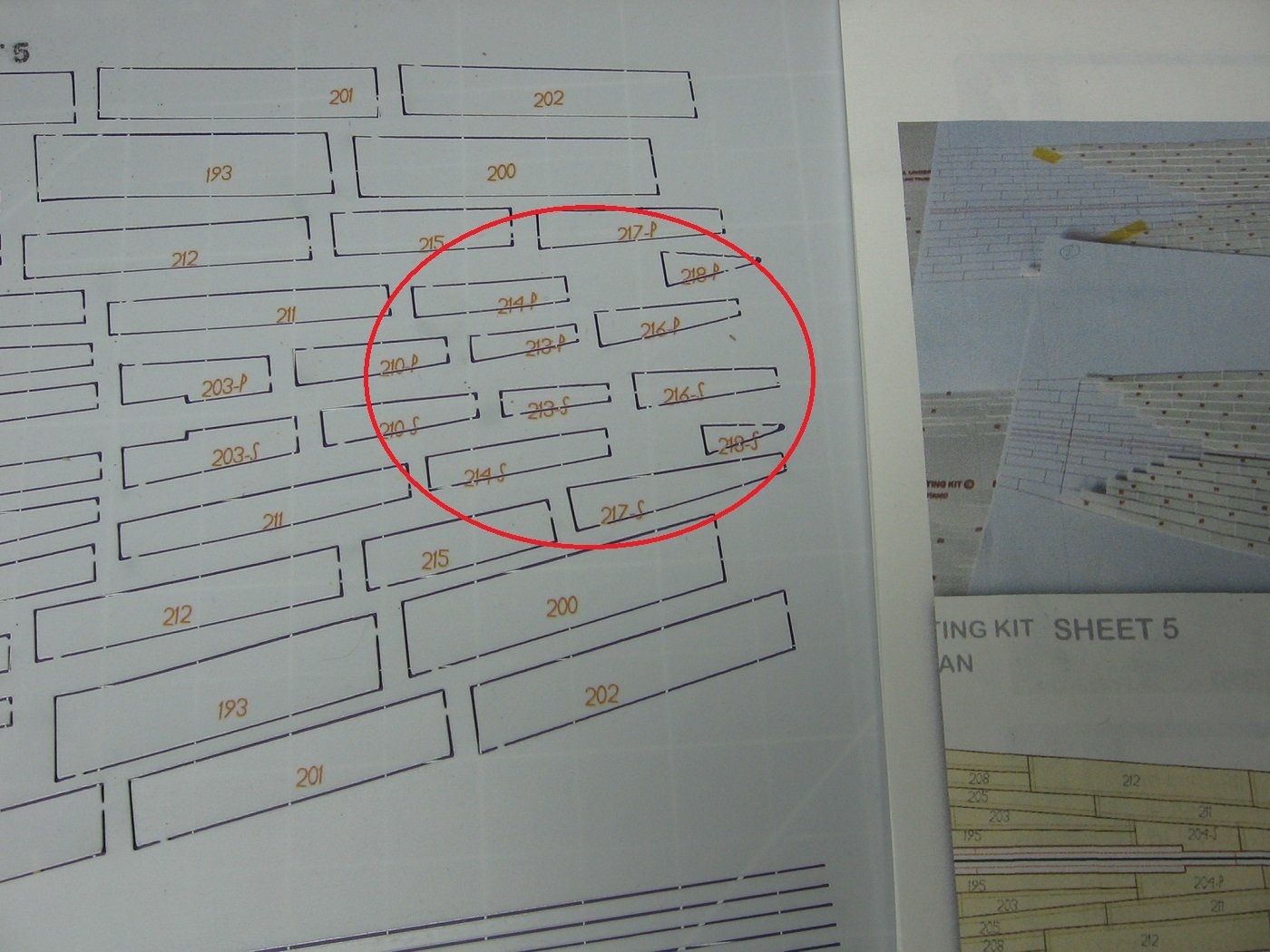
Another labelling mistake from the manufacturer. Plates 203 and 204 of Sheet 5 are mislabeled on the styrene sheet. The template sheet is correct. Seems with each aftermarket kit I've bought and either looked at or begun working with, so far there is at least one issue. Again, not a big deal here, but for a detailed person who expects better, it's a tad annoying. Further, as per instructions, the plates are to be laid in the numbered order. Took a minute or two to figure this anomaly out. Buyer beware when it comes to aftermarket kits, in my opinion. I might just send a short email to the supplier of this kit to give them a heads up on this. Thanks for looking. Cheers, Mark
.JPG.e01073cd0eb7abd345754279248df249.JPG)
-
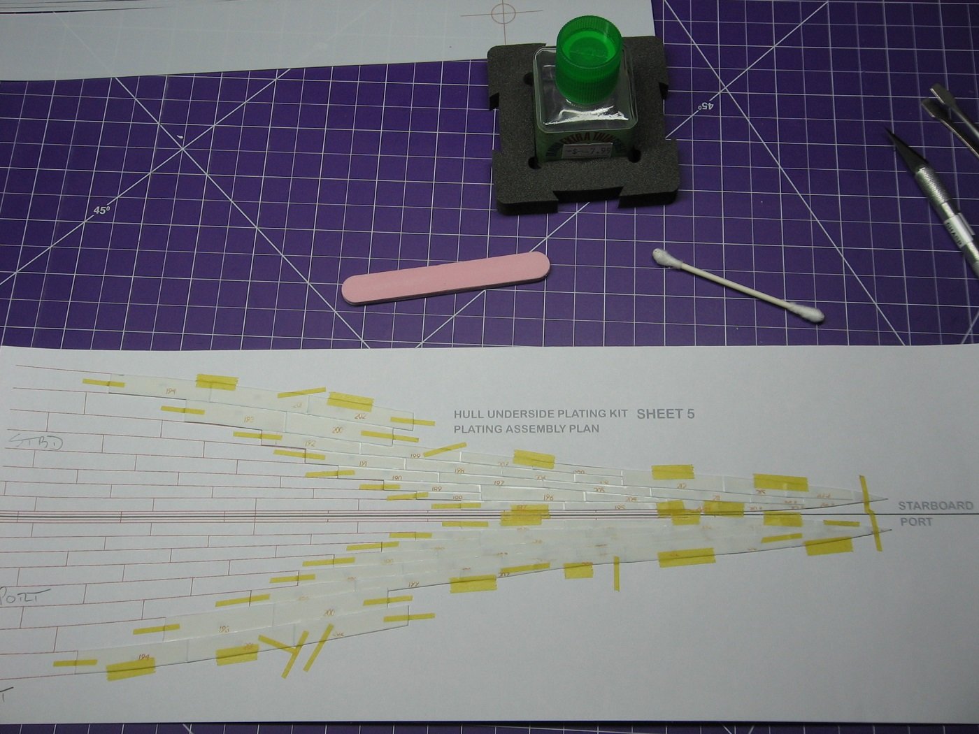
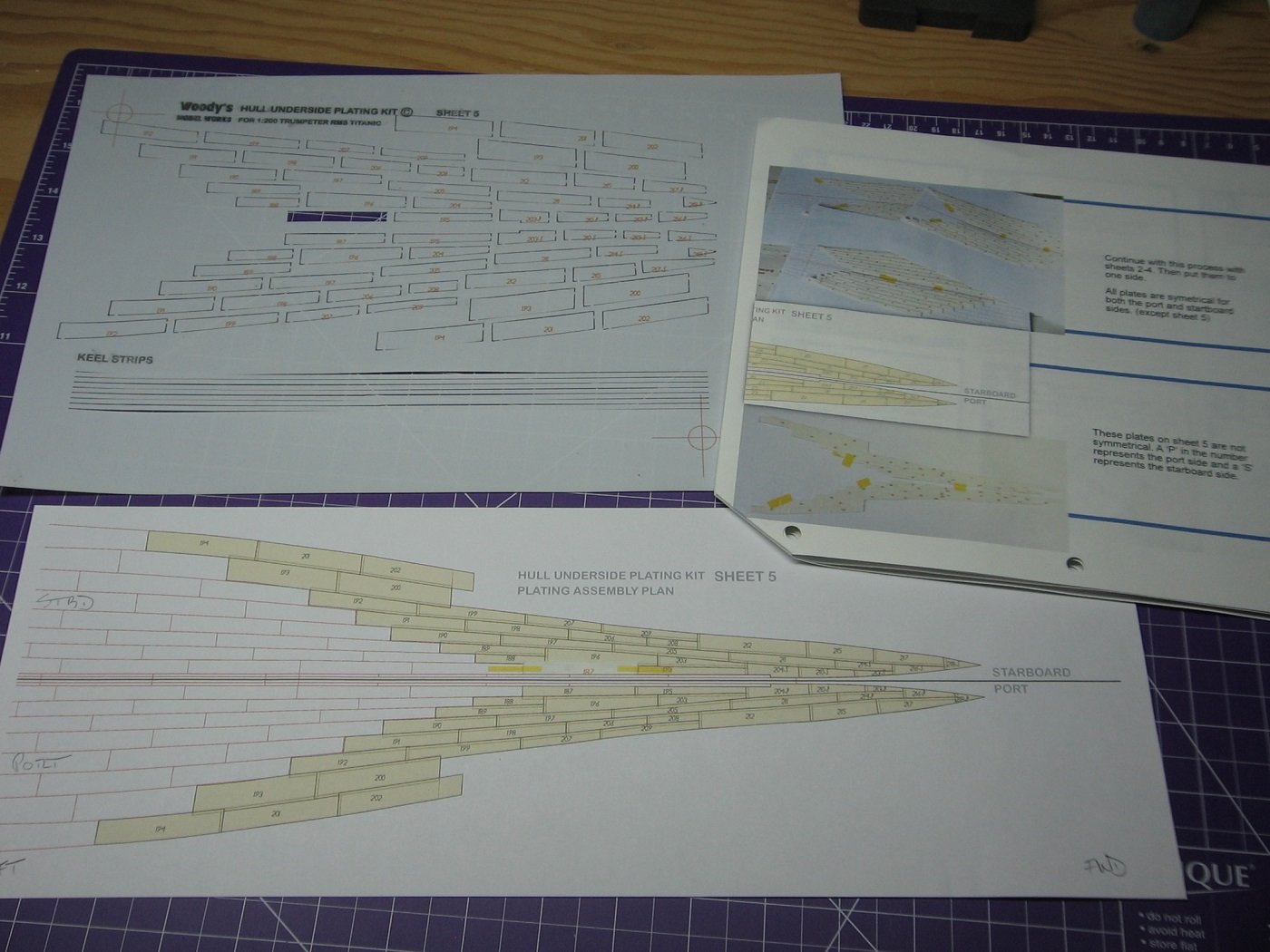
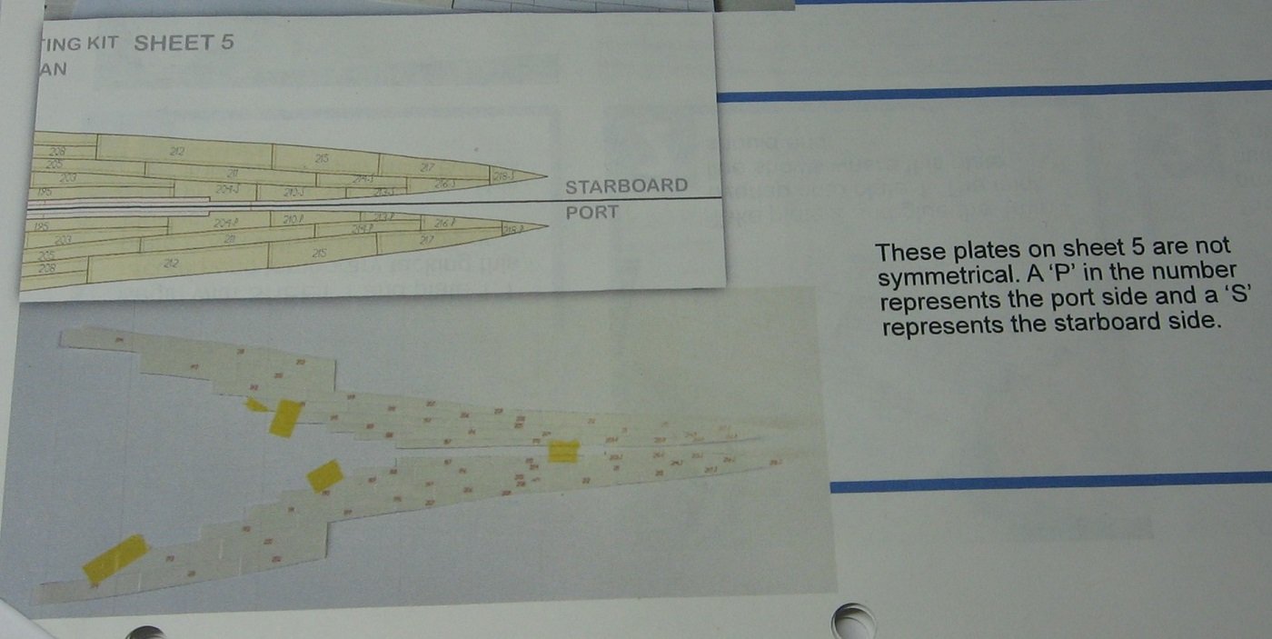
Started Sheet 5 ...... .....as per instructions, noting that some of the forward most plates are not symmetrical to each side.... ....and it didn't take long to discover that these asymmetrical plates are labelled incorrectly. Not a big deal, and I suppose it's irrelevant, if one is paying attention and cuts, then applies, each plate as one goes. Further, it appears that this sheet does not have as many plates as the previous four. Should be able to get this sheet done in less than a week. Thanks for looking. Cheers, Mark
-
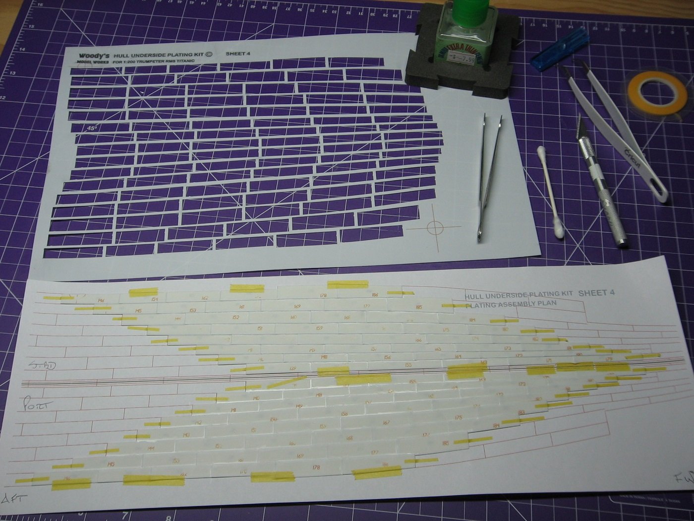
Sheet 4 done. One sheet left. It takes me about 1 hour and 20 minutes to do one row of eight plates. ~ 16 hours for an entire sheet. Hoping to have Sheet 5 done in a week. Thanks for looking. Cheers, Mark
-
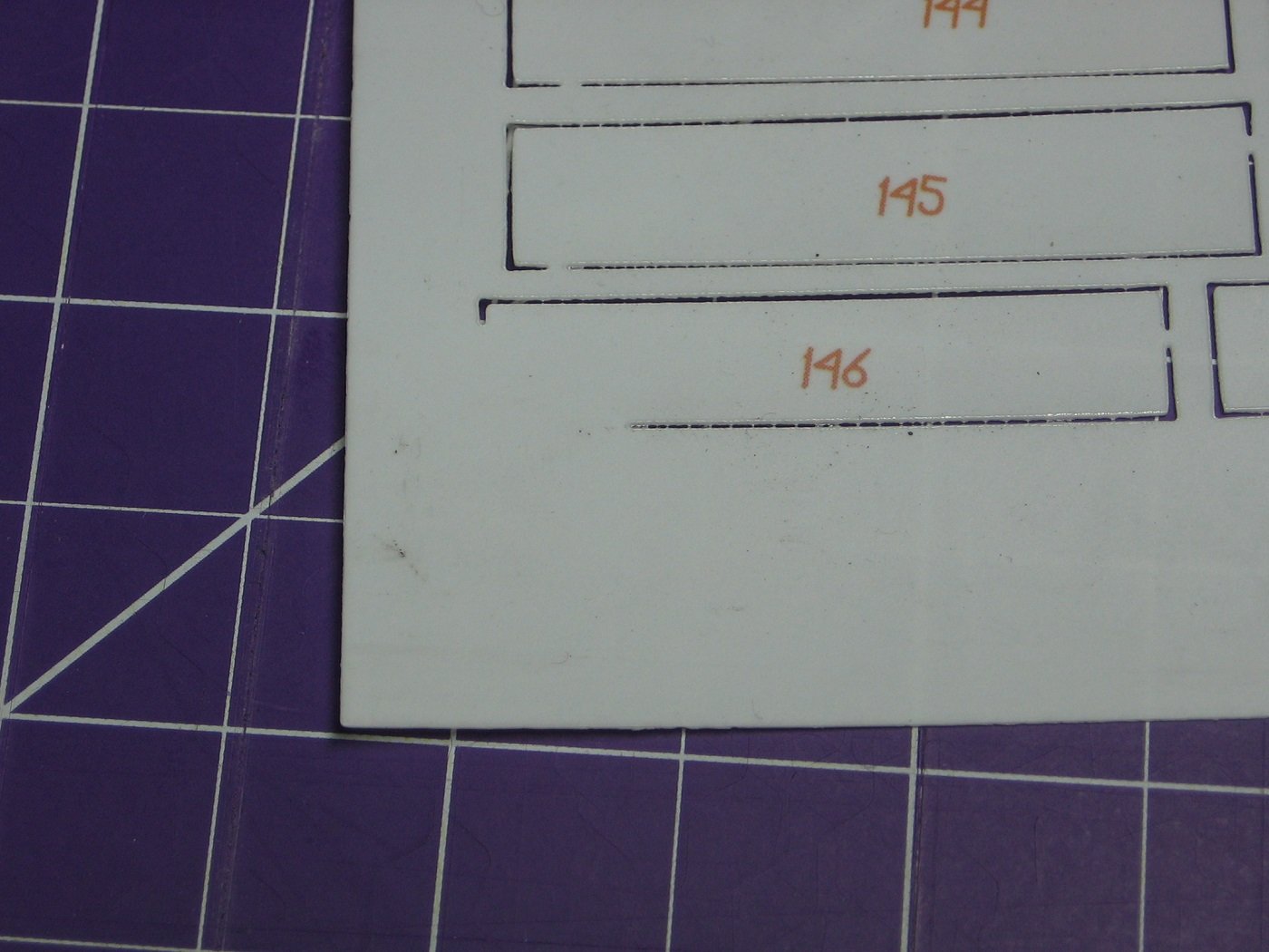
Minor imperfection on Sheet 4. Port plate #146 not entirely cut through. Not a big deal. Cheers, Mark
-
Sheet 2 done, a few months ago. Golf season over, Scale Modeling season commenced. Sheet 3 completed today. Two more sheets to go before applying to the hull. Thanks for looking and cheers, Mark
-
Sheet 1 done. Starting Sheet #2 soon. One recently learned disadvantage to being on a blood thinner as a result of an angioplasty is that back issues are not immune to easily being rectified by a chiropractor. As it is, I have suffered a back ailment (not the first time), that, because of my recent stent implants, cannot be rectified in a traditional "back crack" chiropractor way until said implants have "healed" (6-12 months). A disappointing aspect of this (the back ailment) is I can't swing a golf club without resultant pain and can't get "fixed" by my chiropractor without "back cracking" until said stent healing is complete. I've been worse off before, but not in this scenario, and hoping that this setback can be rectified with modified chiro appointments as well as self care (read: annoying exercises) at home. Point being, I will initially, and maybe beyond, have more time on my hands than expected to continue work on this project this summer. Hoping not, though. Thanks for looking. Suggestions are welcome. Cheers, Mark
-
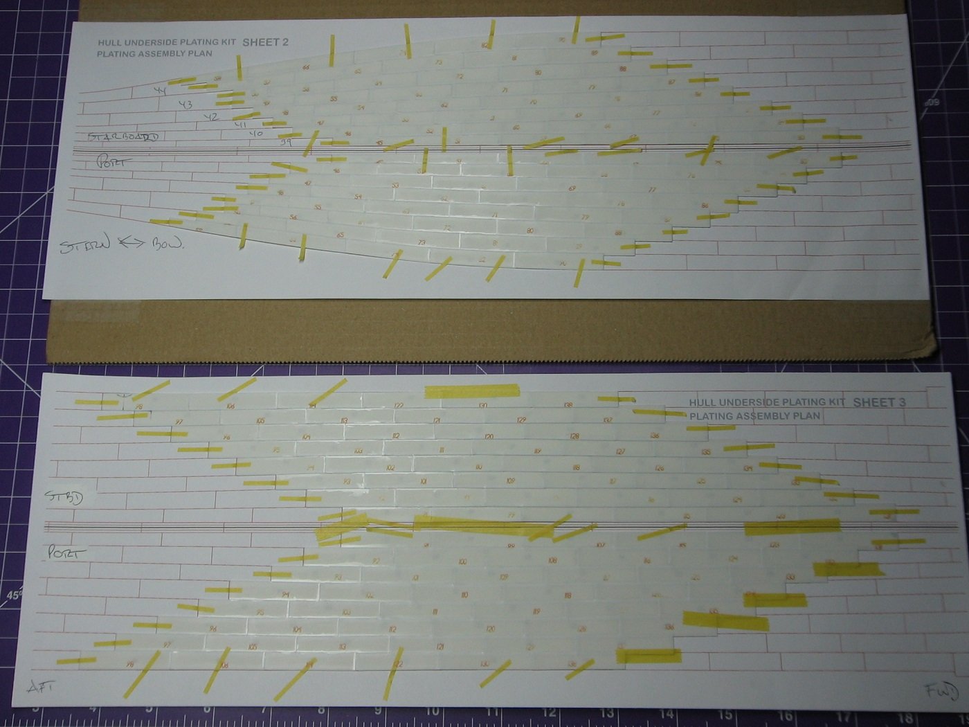
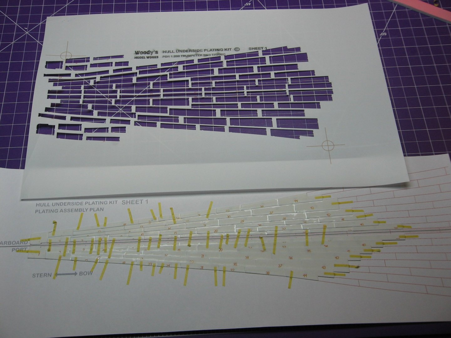
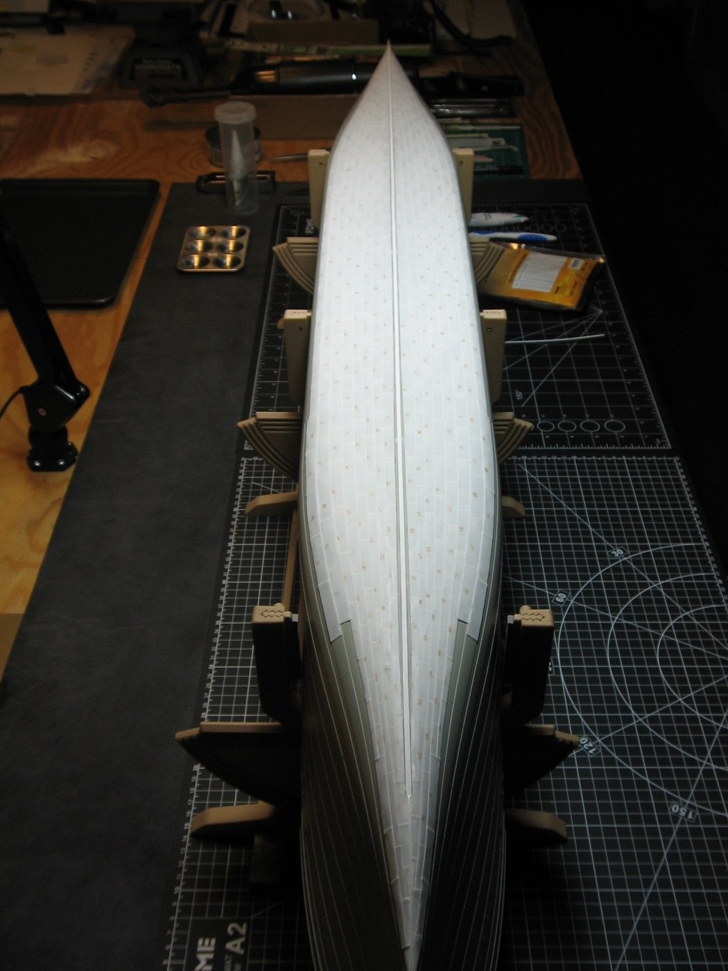
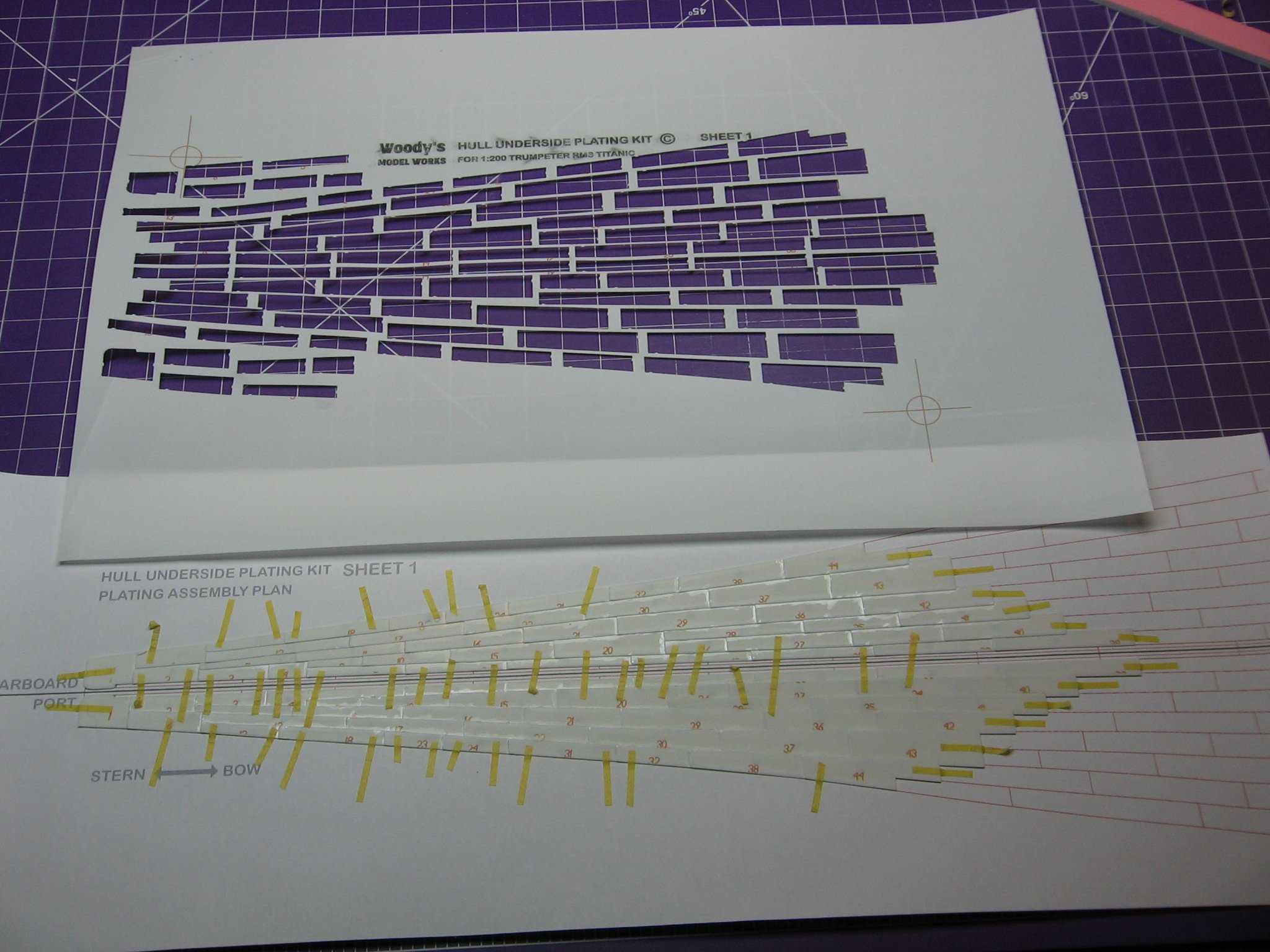
Working the underhull plating kit from Woody's Modelworks (aka Maritime Models) has begun. The idea here is to build the plating in five sections, setting aside each section as it's completed, and then glue the sections to the hull en masse. The seller states (in an email reply) that the thickness of the styrene is 0.20mm. I don't dispute that as it appears, in a side by side comparison to the .005" (0.13mm) styrene I used for the stern plating, to be slightly thicker. As with the stern plates worked, there is a "lip" on each of these plates that I deem necessary to sand down. And so it begins. I think this will be fairly easy, just tedious and time consuming. It's going to take awhile. Thanks for looking. Suggestions are welcome. Cheers, Mark
.JPG.12657bd77c3896e2a7c6564abc422070.JPG)
.JPG.5ece22e0390f73cd2827f6af89fc13ea.JPG)
.JPG.00a704a190b102955eef0bc2e921b30b.JPG)
-
Phil, Very good points. Thanks. Never considered a ruler might be inaccurate. I do not have calipers. The ruler I used is a cheapo bought at a drug store. Anyway, it all worked out. If I'm ever in need of this kind of accuracy again, which I suppose is likely, I will definitely take your points into consideration. Me thinks a Staedtler ruler would be accurate. Cheers, Mark
-
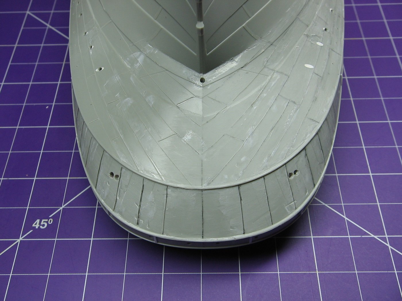
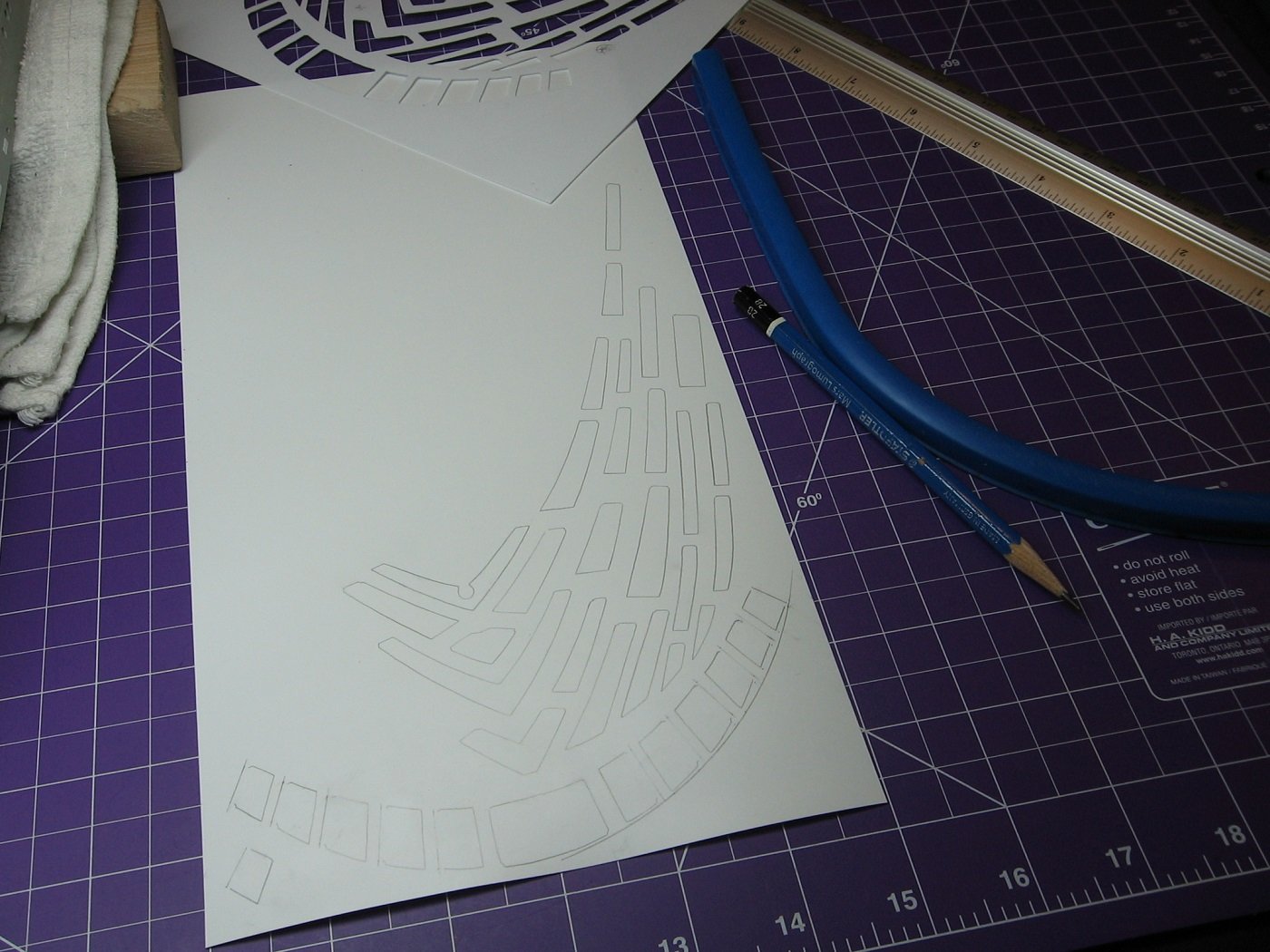
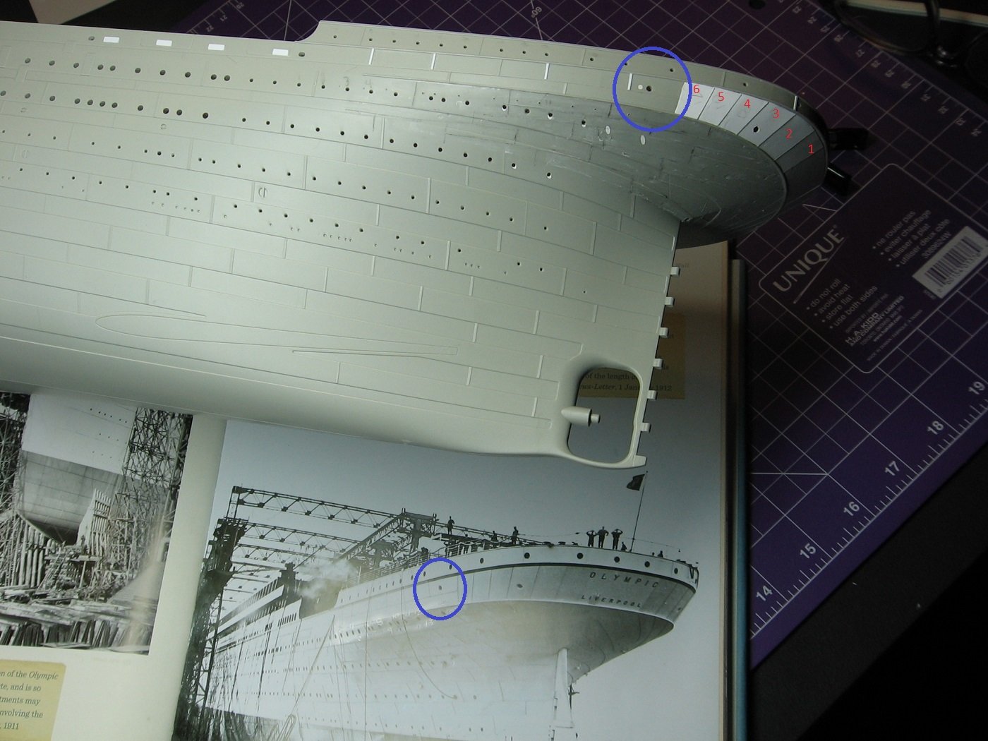
Stern plating completed. As mentioned earlier, I decided to go with .005" thick styrene. So, essentially, I paid $70 CDN for a template and instructions, as, in the end, I did not actually use Midwest Model Shop's .010" styrene kit. . .005" x 200 = 1". According to “Titanic: The Ship Magnificent” (Vol 1, pg 145), the ship's shell plating was various sizes, but 1" thick at the most. .010" is not to scale. Here's a pic of the layout guide scribed onto the hull.... Here's the .005" styrene traced out using the .010" aftermarket kit's sheet.... I used the negative spaces of the original kit sheet. Most of the traced plates on the .005" sheet were smaller than needed. A lot of measuring was required, for most plates, to cut them a tad larger than traced and get them close to right. I added 1mm to the width of each of plates 1 thru 6, indicated in this picture, to bring the whole sequence 6mm further forward and thus a more accurate representation, as indicated within the blue circles. Applied to the Stbd side as well. Some pics of the final result. Immaculate? No. "Museum Quality"? No. But I'm pretty happy with it. The .010" styrene was just too thick and resulted in many gaps and protrusions along the rub rails. The .005" styrene, although maybe still not perfect, results in a cleaner finish, in my opinion. Very happy that the aftermarket kit plate seams now line up with the Trumpeter kit plate seams, as indicated here..... So far so good, right? Not quite. An unavoidable inaccuracy exists with this application. I mentioned a reference to it earlier in this build log and it didn't go away despite applying the correct scale layout guide. To repeat....the top row of portholes on Trumpeter's representation are not high enough. This results in a conflict with the location of portholes on a couple of the aftermarket kit's plates. Here's a pic, before trying to explain it in words..... Contrary to Trumpeter's representation, the line of portholes indicated here on the Olympic, within the green rectangle, are actually in the upper 1/3rd of the row of shell plating they are respective with. Continuing this line with the aftermarket kit in place creates a problem. The aftermost 5 portholes would end up being on the wrong (lower) plate (blue arrow) and too close to the upper adjacent plate seam there. You're damned if you do and damned if you don't with this. The only way to REALLY correct this , that I can see, would be to fill the entire upper row of Trumpeter's porthole locations, bow to stern, and re-drill them higher. A task I'm not willing to do. The lesser of two evils for me was to offset the line of this row of portholes so that the aftermost five are represented accurately as per the shell plates they are associated with (red arrow). A further aspect that had to be corrected, in my mind, was four portholes, (two each side), that needed to be relocated as a result of extending the upper plates by 6mm. The following is a more accurate representation, in my mind.... And finally, in all this, I had inadvertently sanded off a Trumpeter kit seam line on one side. So I purposely sanded the respective seam on the other side off and added styrene strips to rectify. Super stoked that I've completed this step with relatively satisfactory results. I'm confident it will look good once painted. Next up will be Woody's Model Works underhull plating aftermarket kit. Thanks for looking and suggestions are welcome. Cheers, Mark
.thumb.JPG.9cf504fb69e9f2225977659dad384aca.JPG)


-
Sorry I haven't replied sooner. I'm supposed to get an email notification advising me of replies to this log. Not sure how I missed that. Pictures from that other site? Which pictures? The MiniBrass kit? There's a good video or two on YouTube on that one. I have an elderly aunt in Winnipeg. Hate to say it, but I might be out that way in a year or two for a funeral. She's 93. Cheers, Mark
-
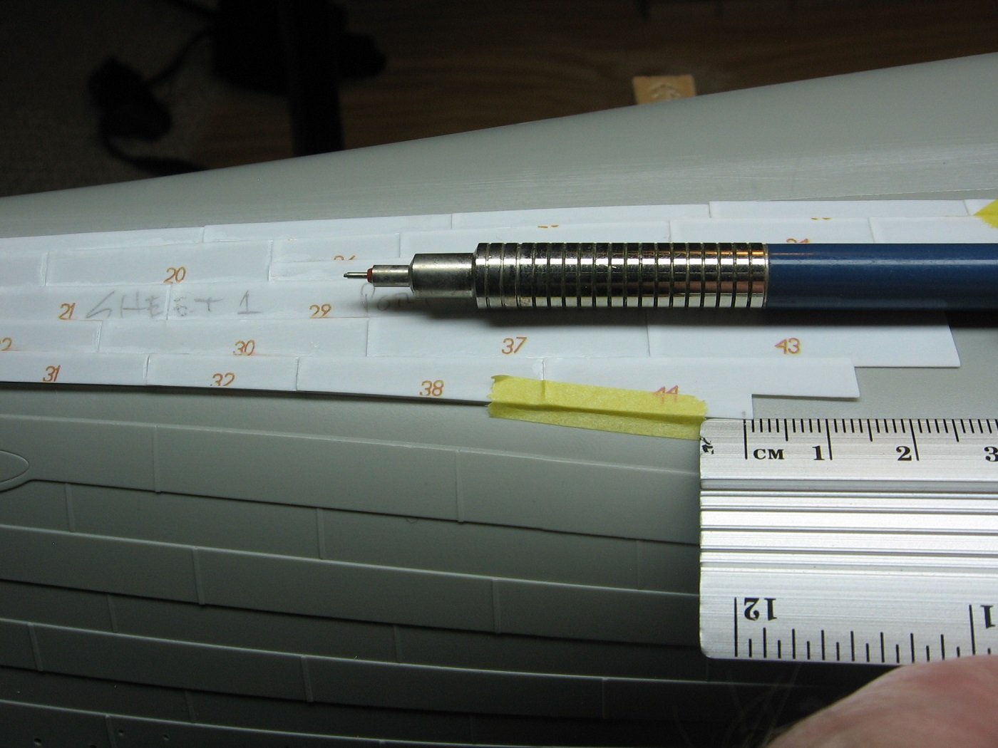
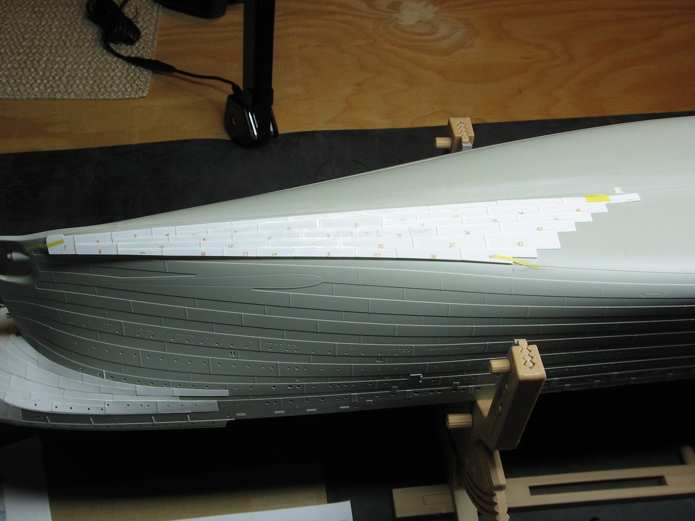
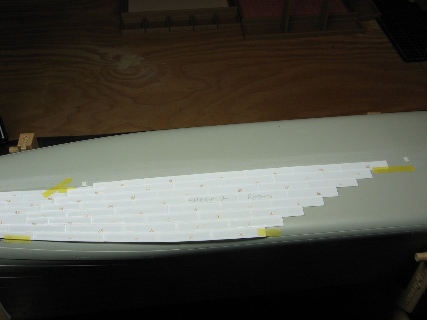
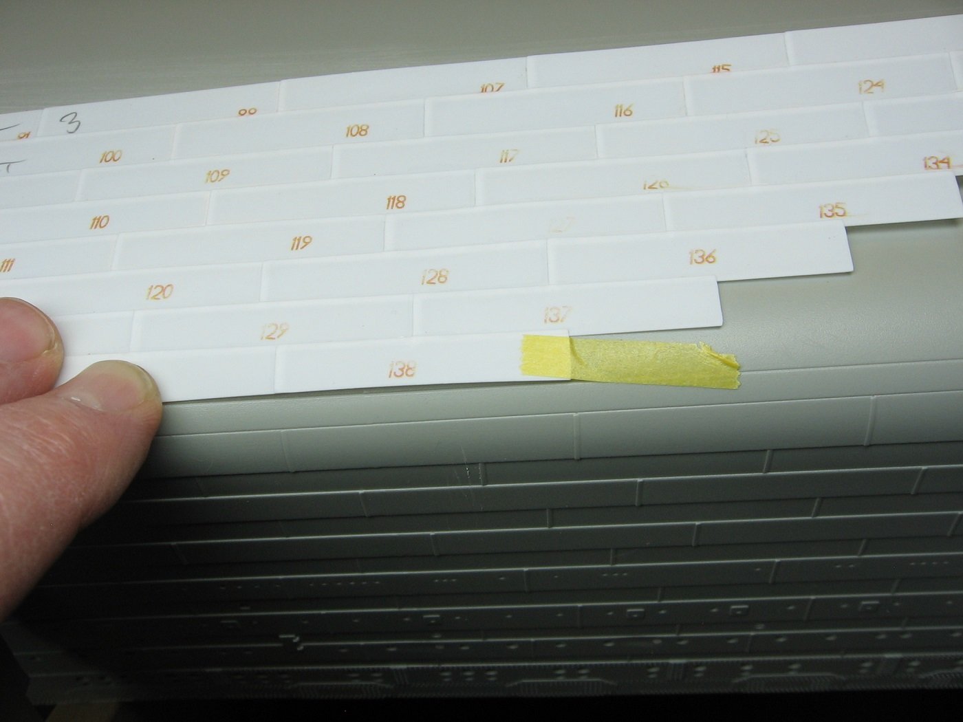
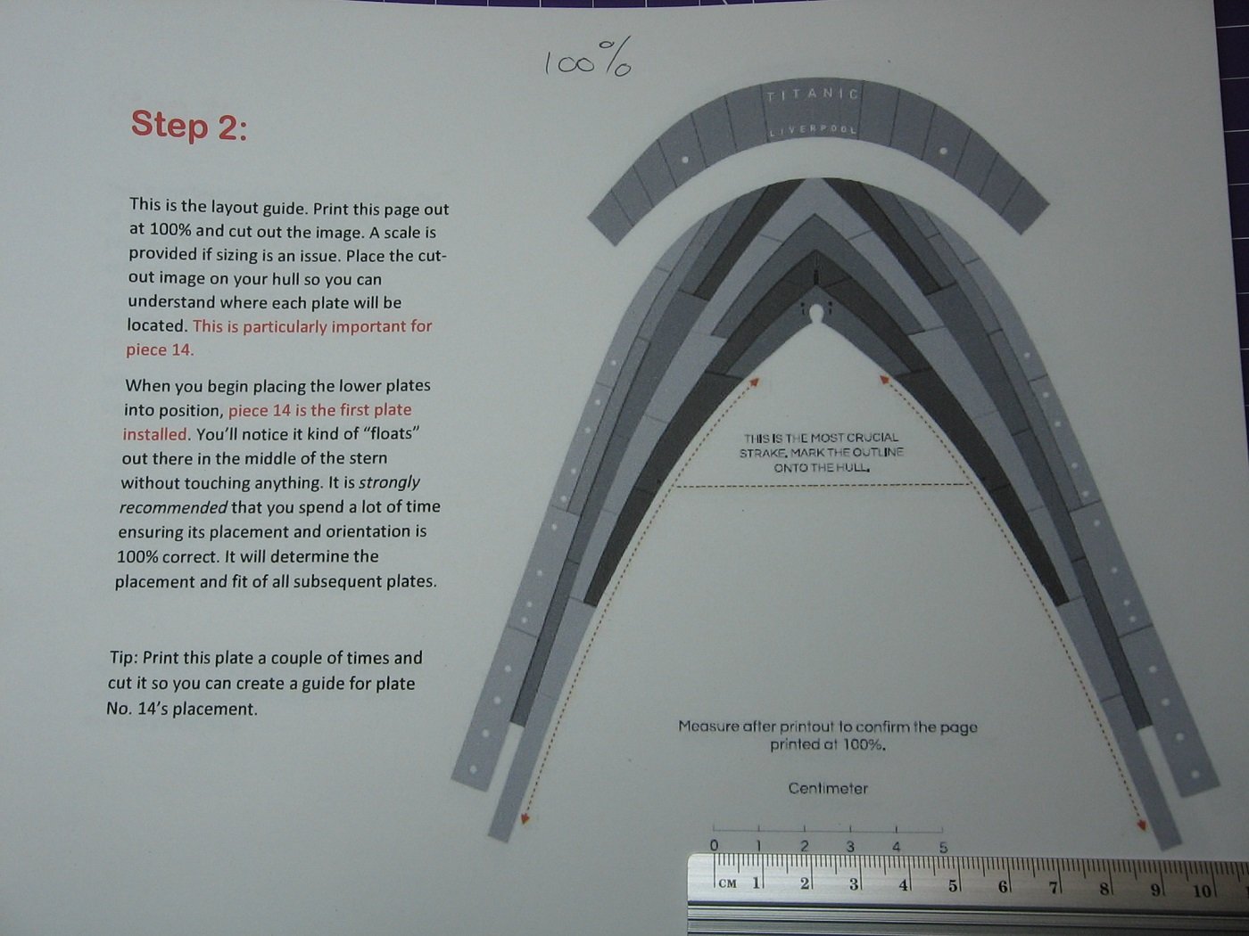
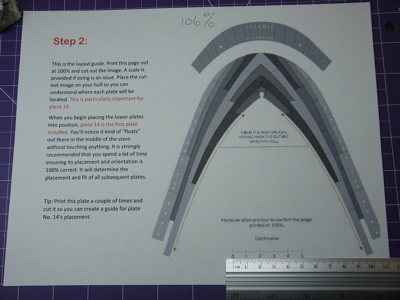
Eureka! Modeler error discovered! Or perhaps oversight is a more appropriate word. Regardless, quite embarrassing, actually. I attribute this to my lack of experience as well as just plain stupidity. Simple as that. But instead of hiding it, it should be mentioned here for a couple of reasons. 1). To help explain how my stern plating application will be immaculate henceforth (ya, we'll see about that), and 2). hopefully prevent the next person using this aftermarket kit from making the same mistake, although I can't imagine anyone else being as dumb as me in this regard. The oversight: Midwest Model Shop's stern plating kit has instructions. They are available on their website in pdf format. Part of those instructions is a layout guide. The instructions say to print that layout guide at 100%, cut out the image, and lay it out on the hull to better understand where each plate will be located. Done. This was prior to my first attempt at applying plates: As one can see, the guide does not line up with the kit seams (red arrow), and why is there a huge gap between the guide edge and the adjacent rub rail? Although not mentioned in the instructions, a further advantage to doing this is from a tip I learned from a YouTube video. Take a hobby knife and cut through the paper at each plate seam line, thus leaving score marks on the hull and thus transposing the layout guide onto the hull itself. But alas, due to the fit issue of the layout guide, I abandoned the use of that altogether and began laying the plates as described previously in this build log. So, why did I do that? Why did I not use the layout guide? This is where the dumb part comes in. After stripping all the plating of my first attempt off, I had another look at the layout guide. Here it is prior to cutting out the image: As one can see, it says "Measure after printout to confirm the page printed out at 100%". First of all, measure what? Ohhhhhhhhh!!! Measure the SCALE!! I did not clue into this my first go around. How dumb is that? On a scale (no pun intended) of 1 to 10, I'd say 10. Secondly, I had my printer set at 100%, so therefore, in my mind, how could my print job not be 100%? It appeared to me that there was something wrong with the instructions, rather than my misunderstandings. Thirdly, I'm not a techy and it hadn't occurred to me that one could print something MORE than 100%. 100% is 100%. Period. Once I realized what I'm supposed to "measure", and actually measured it (clearly in the above picture, this 100% print job falls short of 5cm on the scale), it then dawned on me that perhaps printing at 100+% is possible. Turns out it is. Who knew? Further to "I'm not a techy".....I suppose all printers are not created equal? (insert shrugs shoulders emoji here). A 100% print job on one printer might be 95% on another? More specific instructions on this would have been beneficial for an idiot like me, but I don't not want to pass blame, and I digress. So, I tried printing the page at 105% and that measured still too small by about 0.5mm. So, I tried 106%. Pretty much bang on. Maybe 0.1mm too large. Maybe. Close enough. And voila! Pics of the layout guide in place. That's better. Next step will be scoring the plate seams through the guide and onto the hull. Not mentioned in the instructions, but learned from online...these lines will not be the gospel as to where the plates lay exactly. They are just a guide. But better than guessing free hand. Regardless of all the above, I still disagree with the .010" thickness of the aftermarket kit provided styrene. I've obtained .005" and will be going with that, using the negative spaces of the kit sheet for tracing. Until next time, thanks for looking and suggestions are welcome. Cheers, Mark


.JPG.5b930101e7f8c998e52330503827a2b7.JPG)