Frecap
-
Posts
85 -
Joined
-
Last visited
Content Type
Profiles
Forums
Gallery
Events
Everything posted by Frecap
-
 Hello everyone! I'm continuing with the head. There's a lot of confusion with it. In the drawings from Corel, there's only a template for the Main head rail and the head timbers. I had to draw the lower and middle head rails roughly based on the available projections and model images. The assembly sequence is also unclear. Logically, you should start with the head timbers with the slots cut out and then try to fit the rails. However, I didn't think it would work out that way. I won't be able to accurately match the location of the grooves. Therefore, I did the opposite. I glued the rails, trying to maintain symmetry on the top view and relative parallelism on the side view. Now, I will attempt to incorporate the head timbers into this structure. Yours sincerely, FriCap
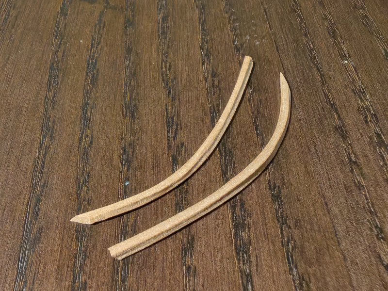


-
Ronald, it's great that you're so meticulous about the little things! Even if it doesn't seem like it, we're doing it for ourselves!
-
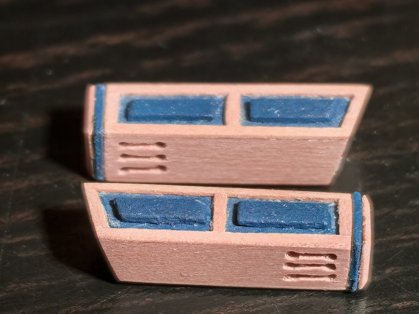
I looked at the photos on the Vanguard Models website, and the trims are not painted. It looks good overall. But you have a very beautiful color for the columns, and I think that with careful painting to avoid damaging the relief, the overall look will be stunning! It's worth trying) Yours sincerely, FriCap
-
I'm sorry, Ronald, but I really misunderstood! Translation costs( And in fact, In my opinion, painted trims on the Brunnels model look more harmonious. Perhaps it depends on the perception of the model as a whole, but also on the fact that they are in the same color scheme with the columns between the windows. Although, on your model, the trims color is different from the Blue Ensign color. If, as you say, you have removed the trims so far, maybe try to paint one strip and attach it, see how it turns out? Yours sincerely, FriCap
-
Ronald, Hi! In my opinion, a three-dimensional decor looks much better than an applique. I think that it is unlikely that you will use flat images when building such a magnificent model. Yes, you've talked about it yourself) Yours sincerely, FriCap
-
... I visited the Vanguard Models website, looked at their products – it's very cool! There are many excellent models, and most importantly, there is an example – the assembly of HMS Sphinx by Ronald-V. Unfortunately, we do not have any sets from this company for sale!( But time is passing, and I think I will be busy building Bellona for a long time, and maybe something will change for the better... Sincerely yours, FriCap
-
Hi, Nearshore! Thank you for the feedback!) Yes, I went beyond the scope of the Korel kit, although I didn't think about it when I started. The photos of the model from this kit inspired me. However, I faced some challenges, such as not understanding how to lay the planking layers, especially in the stern area, when I first started building the hull. When I visited this forum for the first time, I came across a wealth of information from your build log and the Harlequin build log. Looking at the photos from these topics helped me do my work. Then, when I looked at the photos of the models from the museum, I wanted to do some things differently from the set. This, of course, complicates the design and greatly increases the work time. But we are not bound by any regulations, we are just doing what we love, so there is no rush. Your work continues to inspire me and help me make the right decisions. For example, I am currently working on a head, and you have many excellent photos taken from all possible angles. So, yes, this resource helps us and I hope it will help many others who will build this and other models. I wish you good health, patience, and success in your creative endeavors! Yours sincerely, FriCap
-
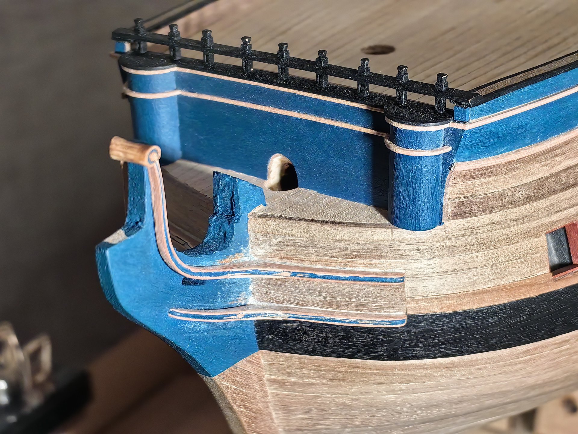
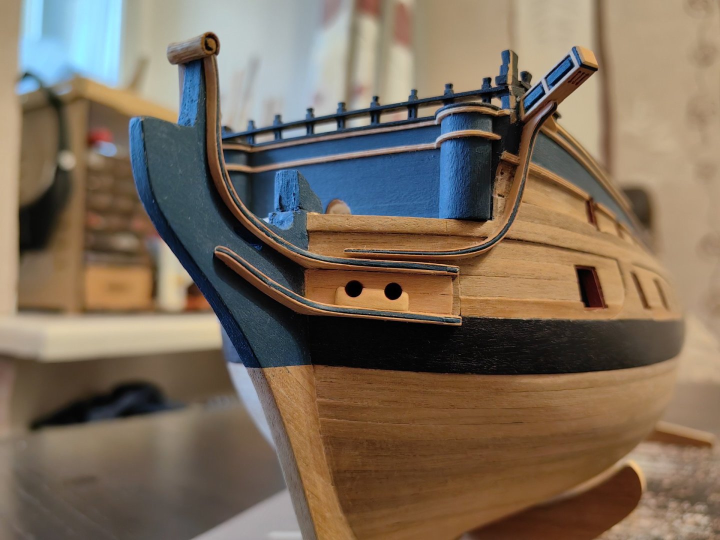
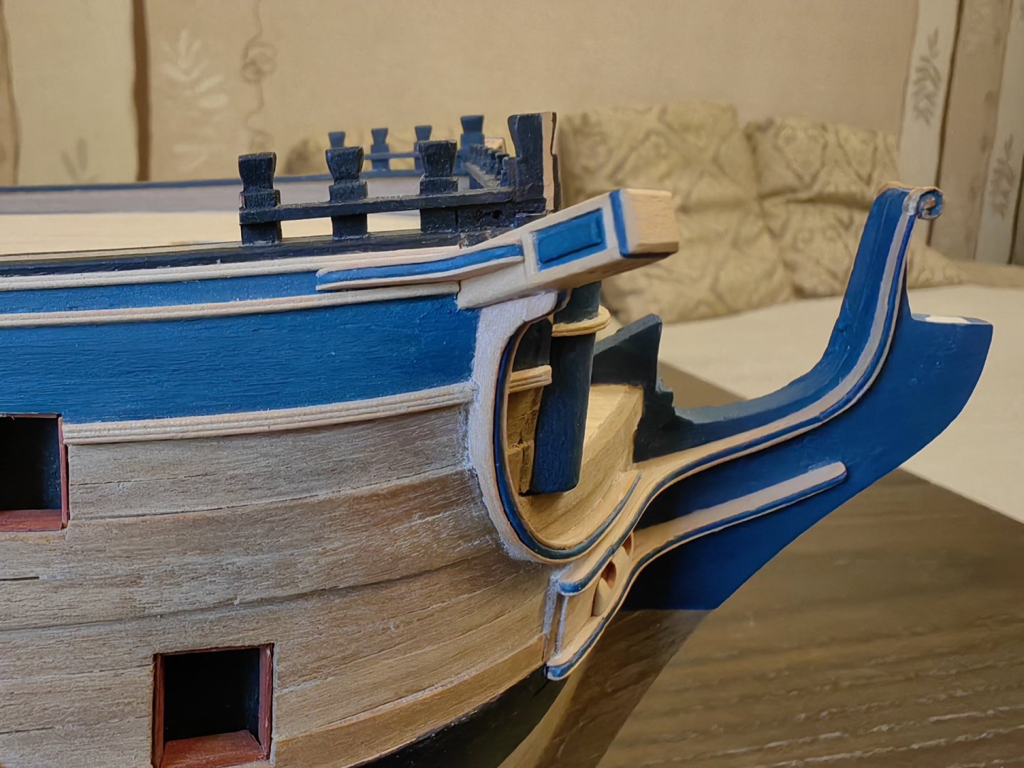
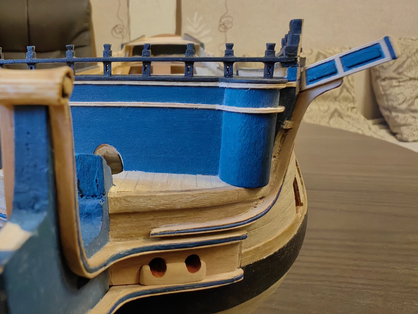
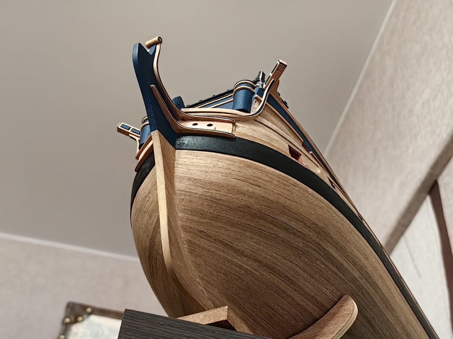
Hello everyone! My work is not progressing as quickly as I would like, but there is some progress) I have decided to make the knees that support the Catheads in a horizontal plane. The detail is not complicated and did not take much time. Much longer had to tinker with the knees Catheads, which smoothly pass into the regels of the head. I decided to make these elements single parts, glued in the same way as the chicks of three rails each. This may have been the wrong decision, as the part needs to be curved in two planes to fit the rounded cheekbone of the ship. Despite my best efforts, I was unable to achieve a perfect fit. I did not have the necessary tools to secure these elements to the hull, so I had to hold them in place with my hands until the glue dried. PVA glue sets quite quickly, but it's not enough to hold the springy ends of the part to the body. Therefore, I had to divide this process into two stages, with a 24-hour break to allow the glue to fully harden. However, in some areas, the parts didn't fit snugly against the body, and I used small pieces of wood to fill in the gaps. I'm not entirely satisfied with the result, as there are still traces of glue visible in the corners of the glued surfaces, which I haven't yet managed to remove. Visually, the knees appears to be more protruding than it should be. But I won't be doing that anymore. I also cut the hawse hole, installed the Navel woods, and installed the hawse hole bolster. That's all for now, and the remaining head regels and head timbers are next in line... Sincerely, FriCap


-
Hello, Nearshore! You've done an excellent job, as always - carefully and with love! Each new detail adds authenticity to the model, and it looks great! It's great to have our loved ones supporting us in our hobby! The organizer your wife made is absolutely amazing! I agree with you about the casting quality of the set. I found a link on the internet to a nose figure of Bellona that someone made for the Shipyard set, but I think it would be suitable for our sets as well. There's not only a nose figure, but also various decorative elements. You may want to use this now or in the future. Here's the link: https://www.thingiverse.com/thing:6776867 You'll need an SLA 3D printer to print this. Just experiment with the scale. Regards, FriCap
-
Hi, Ronald! It's clear that the Vanguard Models kit is beautifully crafted, but without the right hands, it's worth nothing!) As always, I am impressed by your work and attention to detail! I can't wait to see how stunning the model will be once you're done. While I rarely use standard photoetching in my work, seeing the results of your painting, I'm considering incorporating this technique. Yours sincerely, FriCap
-
Good afternoon and Merry Christmas to all! Happiness, health, and good luck to you and your loved ones, and new interesting projects!

-
Ronald, hi! I like your well-equipped workspace. Doing what you love becomes even more enjoyable when you do it in a comfortable and cozy environment! I also want to compliment you on your choice of color scheme for your model. The colors all blend well together. I especially like your blue XF-18. By the time I asked you about it, I had already painted the case, otherwise I would have used this particular color. I used Russian-made paint, and I had to mix several colors to achieve a more or less accurate match. But it's what it is. In addition, I have a different material and color for the case. Now I'm also thinking about what color to paint the decor. In my opinion, the color should be somewhere between gold and ivory. The time has not yet come to make a decision, so I will be watching your experiment with interest. I am confident that it will turn out beautifully!) Good luck and happy holidays! Sincerely, FriCap
-
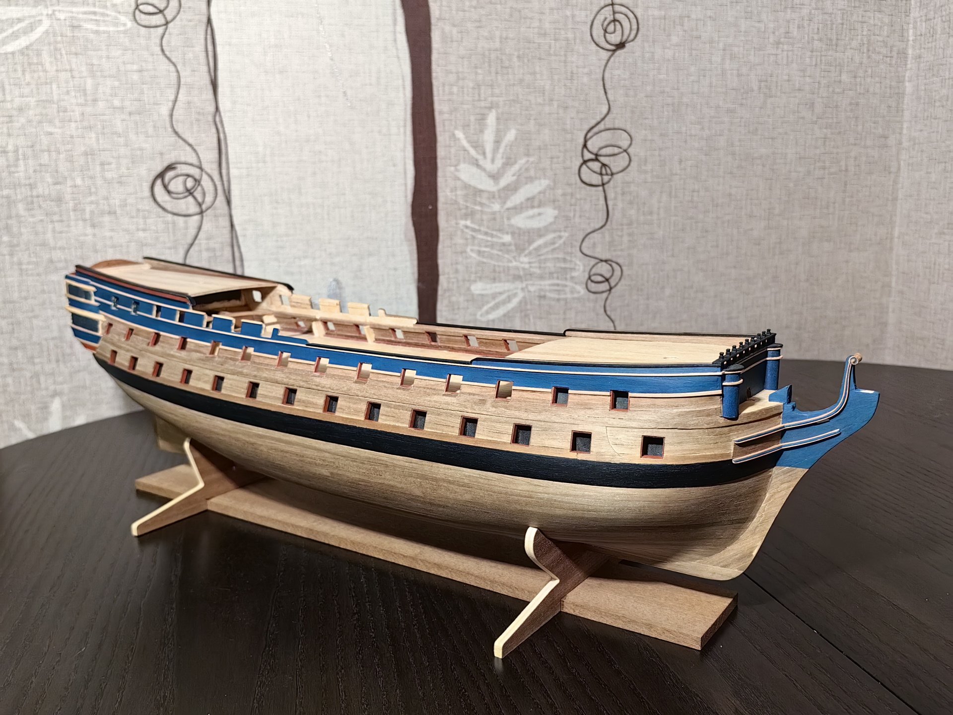
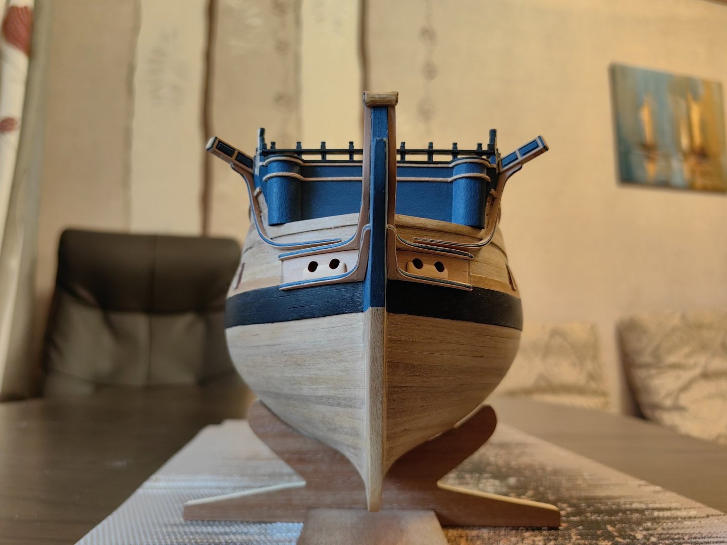
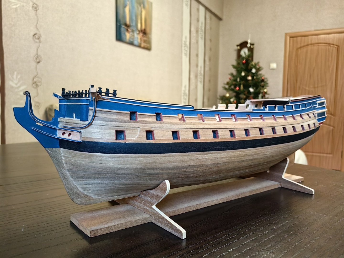
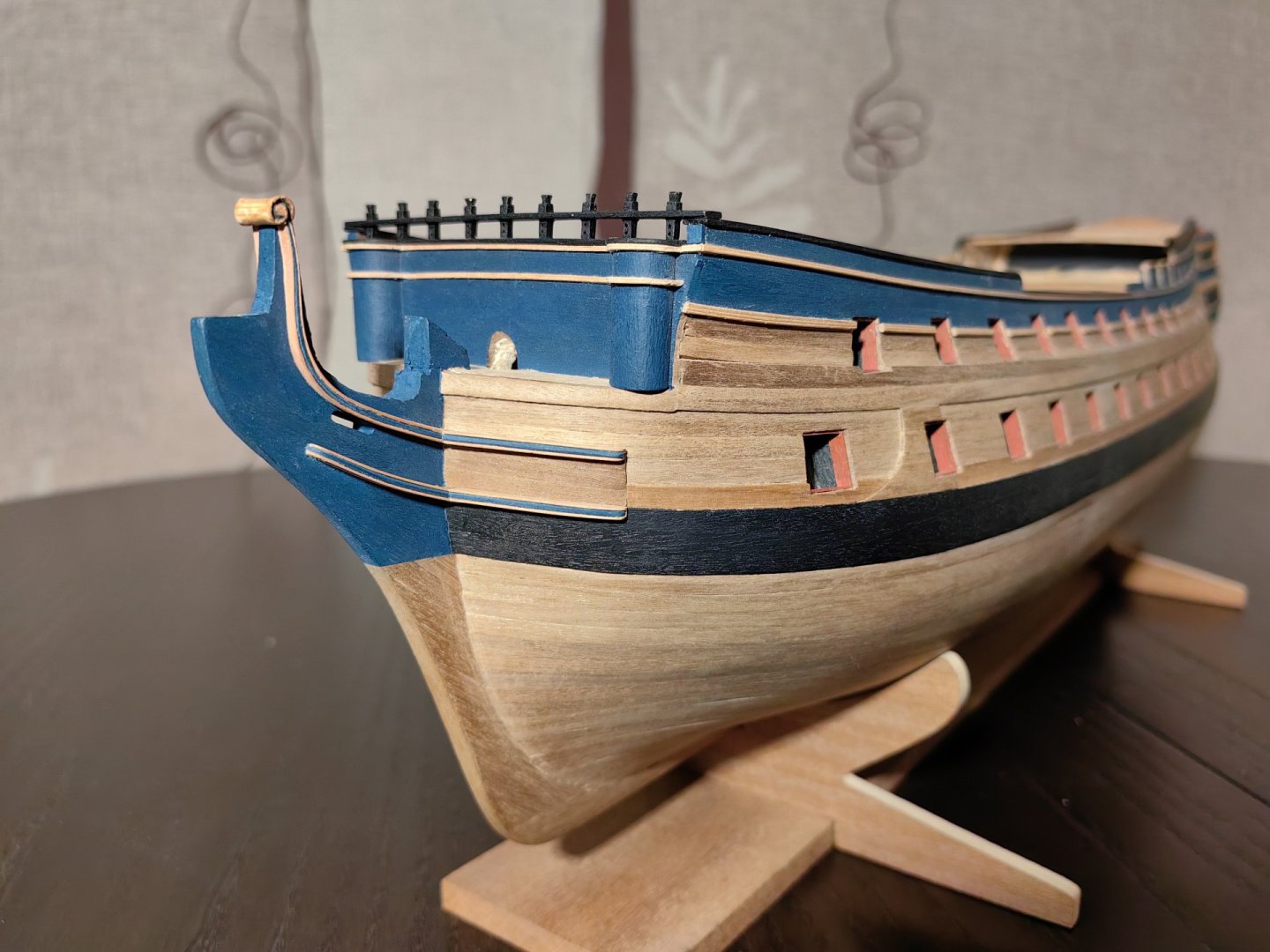
Hello, Nearshore! Thank you for your feedback and evaluation!) But of course, I am not an expert in our field. When I started building Bellona, I had no idea that I would add my own elements to the model. As I studied the photos, I began to think about how to improve the design. Your model has always been an inspiration for me. Even before I registered on this forum, I downloaded photos of your work and studied them countless times, learning about the placement of various elements. You started earlier, and I was in a better position to learn from your excellent work. I also like the colors of natural wood, and I didn't initially plan to paint the model. However, I thought that a touch of blue wouldn't detract from its appearance, and I used the Middleton museum model as a reference. It may seem that there is more blue than should be, but I think that as the hull grows with external structures and subsequently with rigging, it will not be so striking. And the hull will be darker after varnishing ... And of course I am interested in the history of the ship and everything that is associated with it. Everything that I found is on the Internet, in open sources. Of course, everything that I have on this topic, I will be happy to share if you have any questions. Let me wish you good luck and patience, may this wonderful hobby bring you the maximum pleasure! Happy holidays to you and your loved ones! Sincerely, FriCap
-
Yves, hello! I've seen the Bellona made by your hands. It's a great job, done with care and love! You've done an excellent job. It doesn't matter what ship served as the prototype, we're doing what we love, and the main criterion for evaluation is that we enjoy it ourselves. Yes, I've been interested in the history of this ship, but I'm still in the early stages of building the model, and I hope I have the perseverance and patience to see it through! Good luck with your new projects! Sincerely, FriCap
-
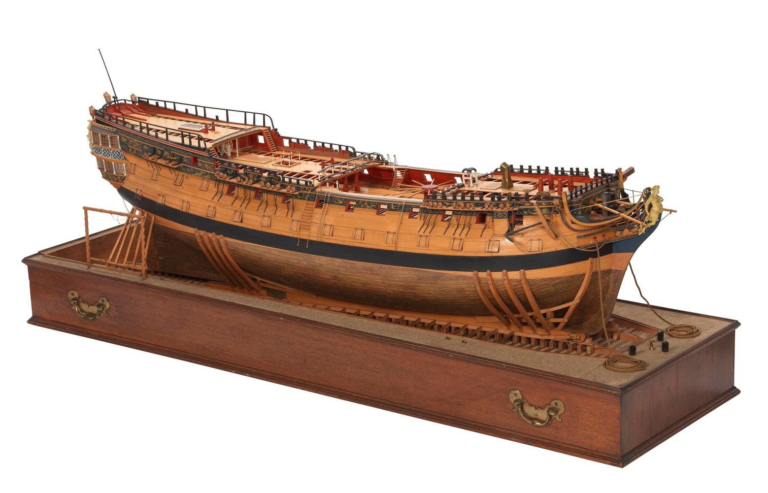
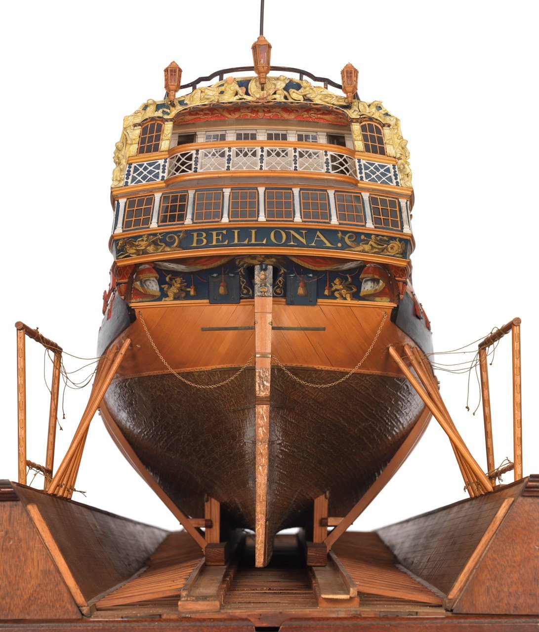
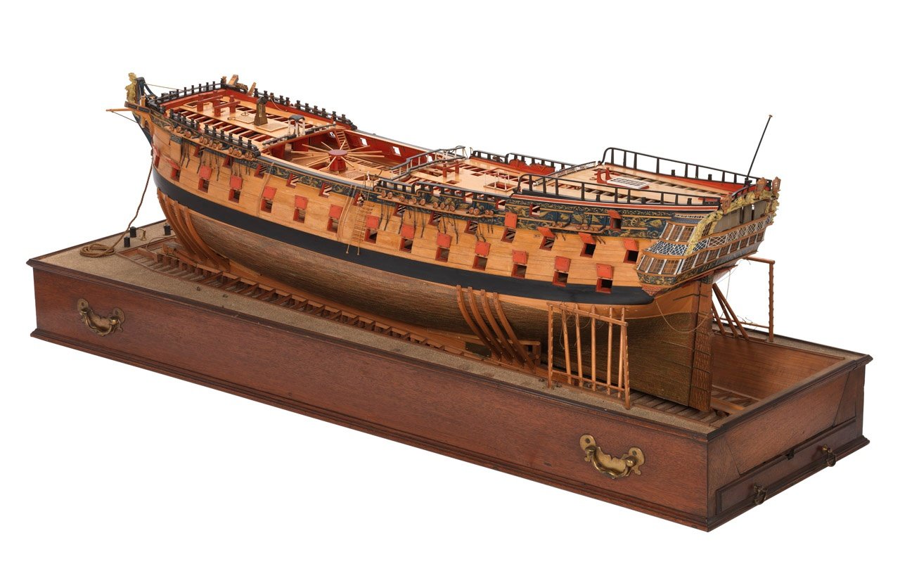
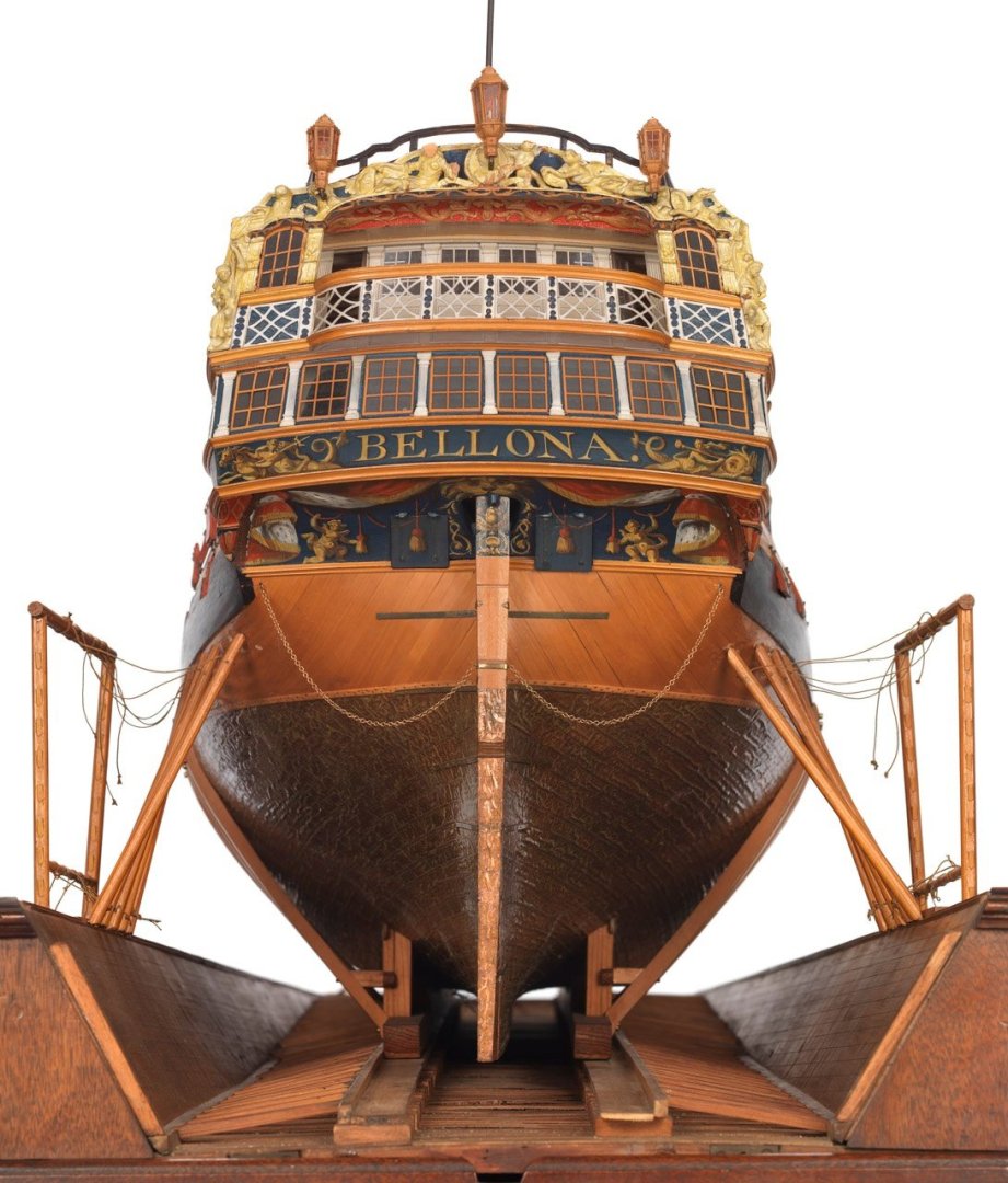
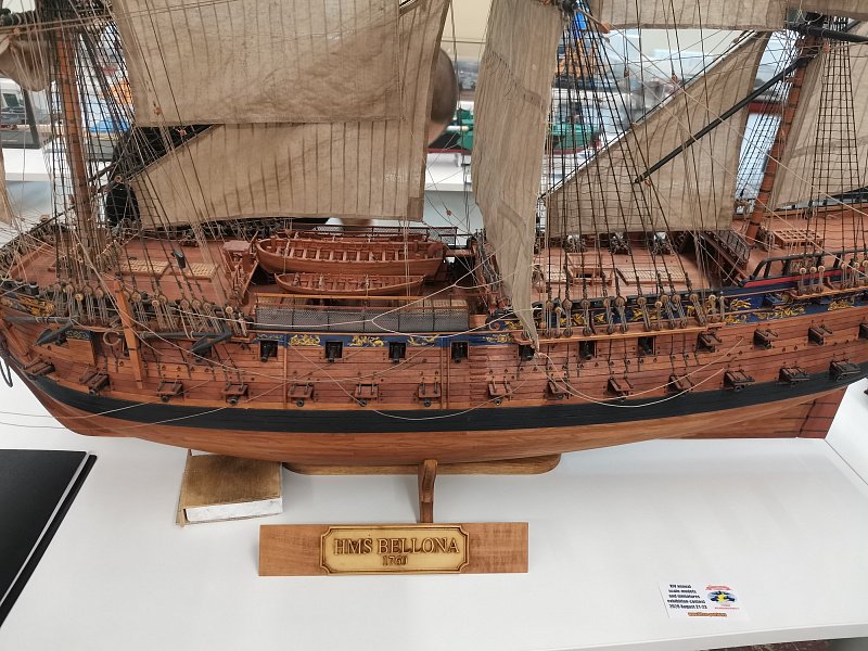
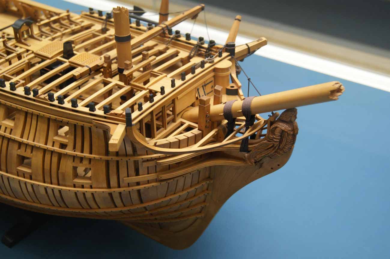
Yves, do you mean the model from the National Maritime Museum in Greenwich? Specifically, this model shows a third-rank battleship of the "Dublin" class, not the "Bellona" class. There is a difference. It's all about the history of the model. This particular model was commissioned by the Surveyor of the Navy, John Williams, as a gift to King George III during a scheduled audience. Williams was pushing for government funding to cover His Majesty's Navy ships with copper sheathing. The plan was to cover the entire fleet with copper, which would have been extremely expensive and required a significant increase in metal production. The protracted fighting in the American War forced the blockade to be conducted in an extremely unfavorable long stay in the waters of the Caribbean, where, after the loss of colonial naval bases, the English fleet suffered losses from the shellfish teredo ("shipworm"). The ship "Bellona", by that time already an old man, was the king's favorite - it was with the launching of "Bellona" that the reign of the long-lived king began, and George treated the ship like a godson. The model was intended to impress the king, and it also served as a demonstration of John Williams's technology, including methods of sheathing, insulating layers, and more. Since there was no time, a model of the first seventy-four guns ship was obviously taken, covered with copper for demonstration, and decorated to look like a Bellona. The ship itself was sailing near India at that time, and apparently there were no drawings for comparison (and they are) at hand. It's funny, but the Greenwich collection contains not only the original drawings of the Bellona, the first ship of the largest series of 74-gun ships, but also a model of the work of the Navy Surveyor Thomas Slade. So the photos show a certain 74-guns ship of the "Dublin" class, with a working stand that simulates the ship's launch (the copper coating was done by tilting the ship, and it was pointless to bring the ship into a dry dock and put it on a launching sled - this is clearly an unsuitable model for explaining the technology, let alone the idea of mass copper coating of the entire Navy!). The audience and demonstration were a success, and the king signed the relevant decrees. For the first time in the world, in less than two years, the entire British Royal Navy was copper-clad at the government's expense, as part of a government program. The first ships to receive copper cladding using Williams's technology were... of course, the Bellona and the Victory. The Middleton model is a great example to follow in many ways. In my work, I try to do many things the way they are done there. The CAF Model kit is most likely based on this model. However, even within this kit, each modeler can do many things in their own way. For example:

-
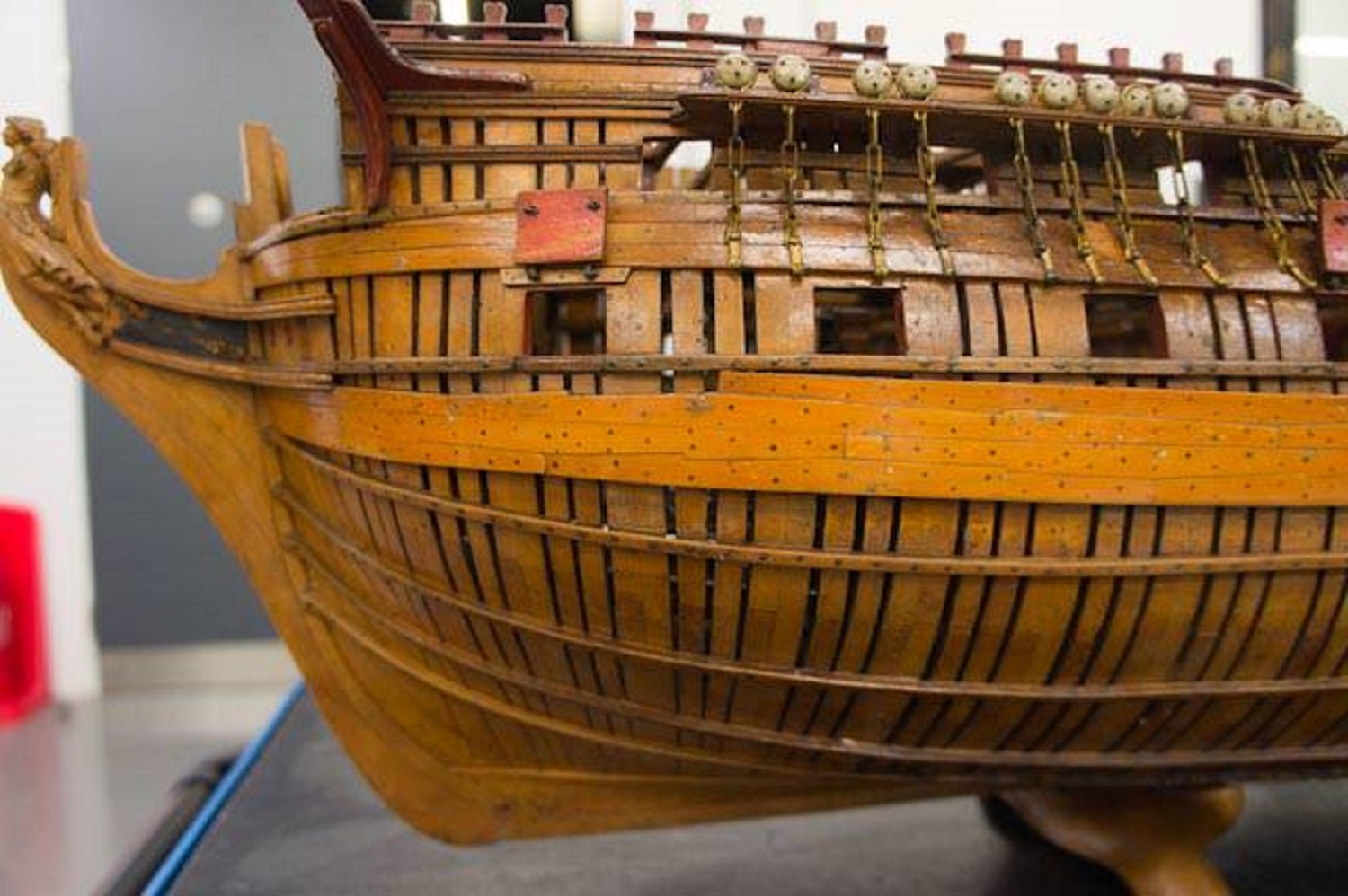
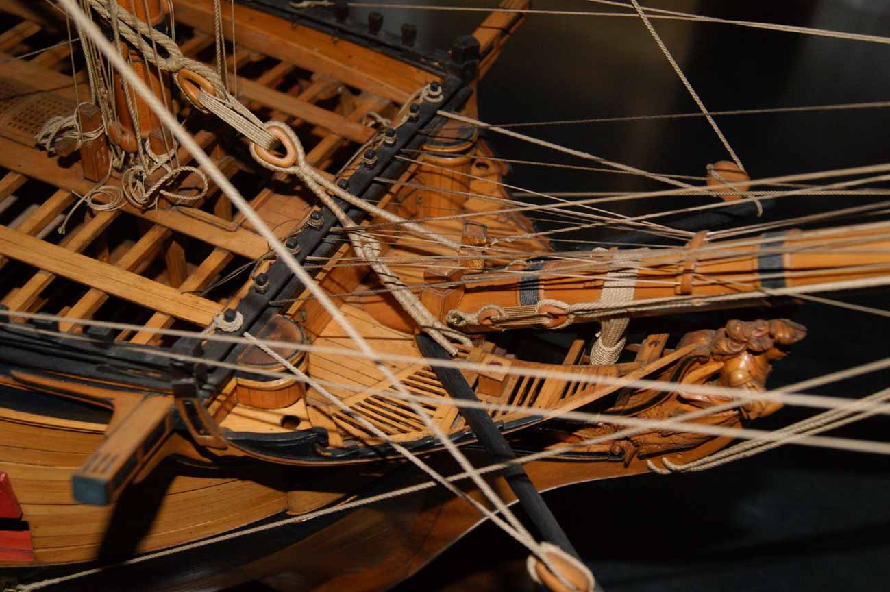
Hello, Yves, thank you for your comment. I haven't decided yet whether I'll make this knees or not... It looks good as it is. However, I would like to disagree with you about the necessity of this knees. The krambol was used to lift a multi-ton anchor and secure it to the side of the ship, bringing it to the stern. It is evident that the krambol had to withstand tremendous loads in two directions, which were compensated by these knees. The models from the Greenwich Museum demonstrate the presence of these knees: Edgar, Egmont, Thunderer, Warrior And the Slade model, unlike the later Middleton model and even more so the modern Lavery anatomy, is the exact prototype on which the ship was built. And the "Installation Party" of the series consisted of not one, but three ships. Bellona, Dragon, Superb. The Dragon model, which also shows this knee, has been preserved in Greenwich. In my opinion, these knees do not spoil the ship's appearance at all. Sincerely, Frecap
.jpg.9aa12b7891f82c8eaf908f549720e6b5.jpg)
.jpg.85c0c8ab7500f0134e062e6e4413c866.jpg)
.jpg.6662025a5fbf8467d63d8ae6594df0ec.jpg)
.jpg.fadf6fc74dd54bec291de8519a55a854.jpg)
-
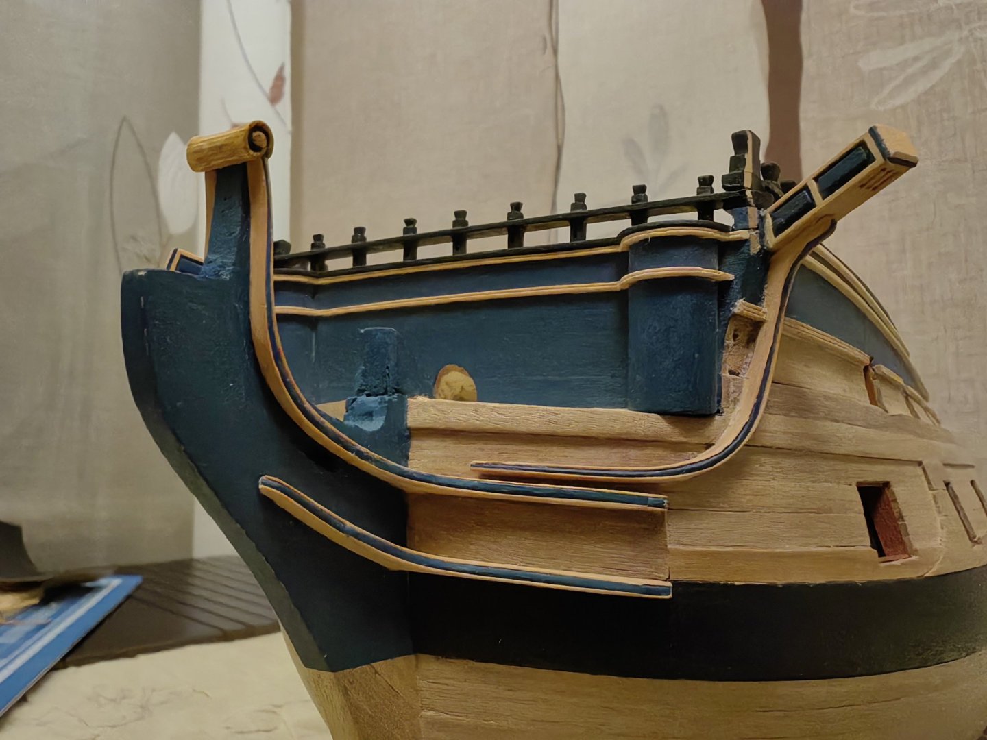
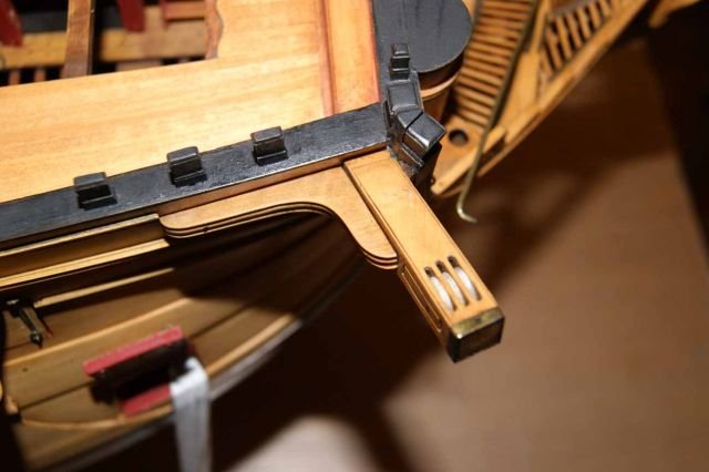
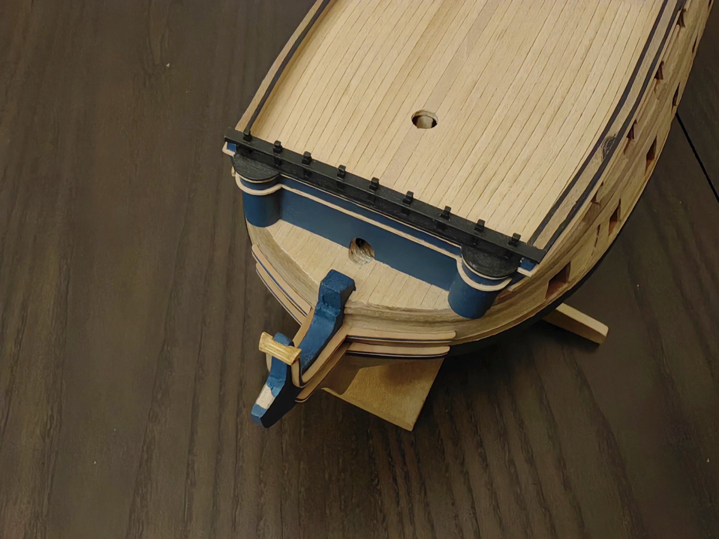
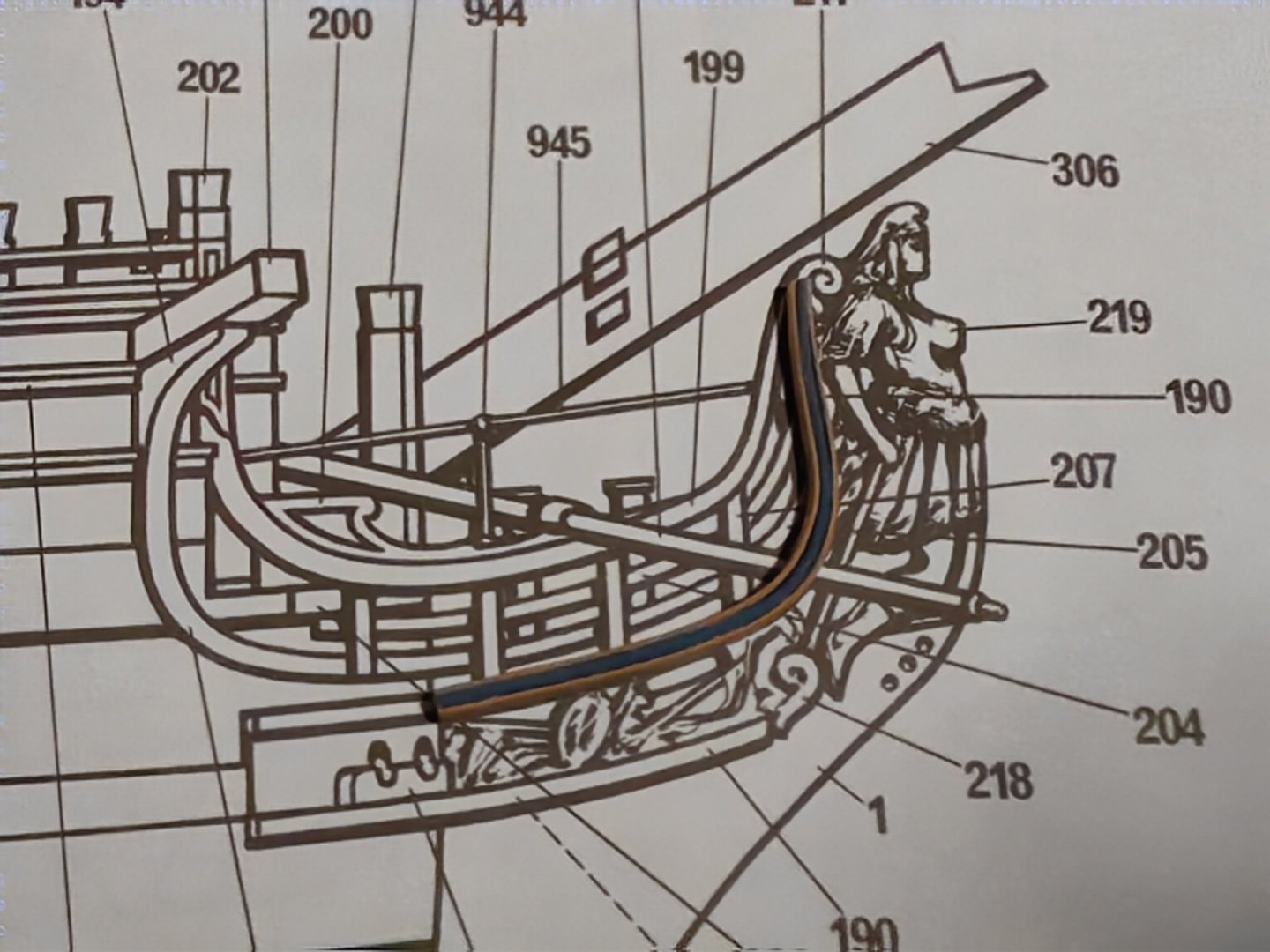
... Looking at the photos of the museum models, I noticed that Thomas Slade's model has catheads supported not only by the saportus, but also by a knitsa pointing towards the stern. However, this detail is not present on Charles Middleton's model, in Lavery's anatomy, and certainly not on Corel's drawings. Since I am building a Bellona model, I believe it is necessary to include this element. Unfortunately, I have already installed the catheads on the model. It's not difficult to make a knees, but I don't want to remove the catheads, so I'll have to carefully cut off the back of the decoration to attach the knees to a flat surface.
.jpg.6a396939093b8ef9321ca62e33e8e2c9.jpg)

-
🙂
-
Thank you, Ronald! But there's no more putty left. I've scraped it all off).
-
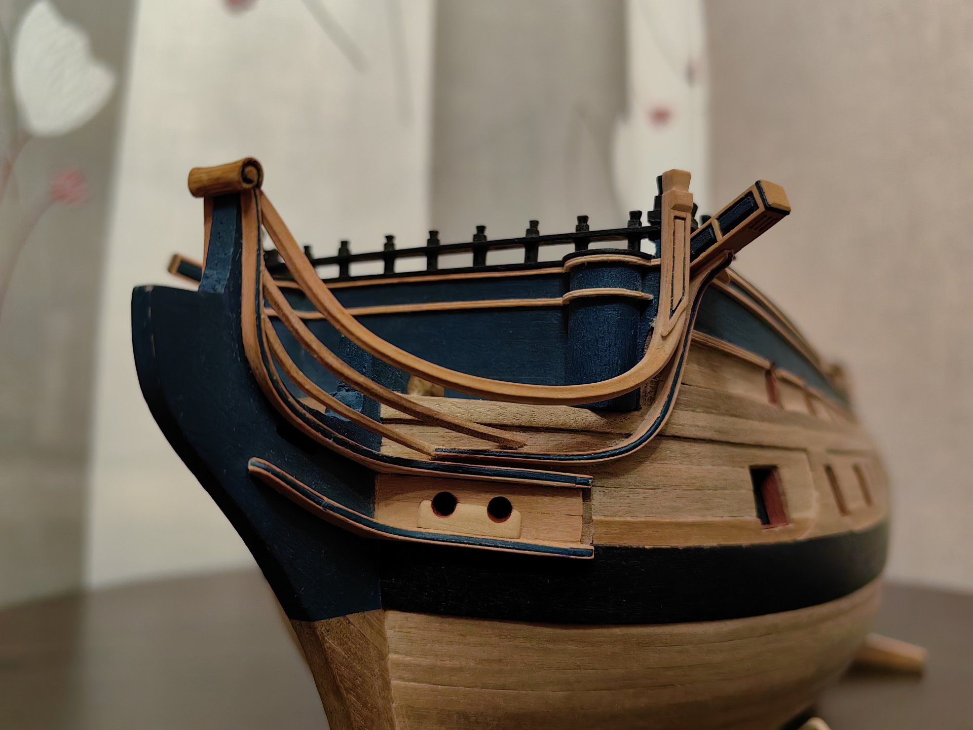
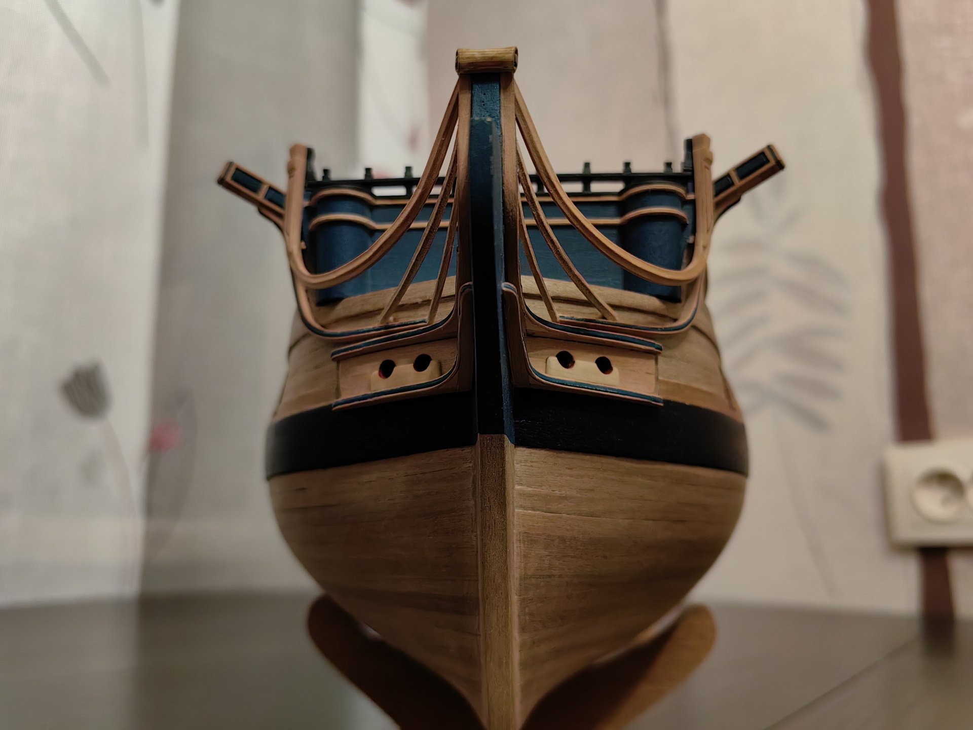
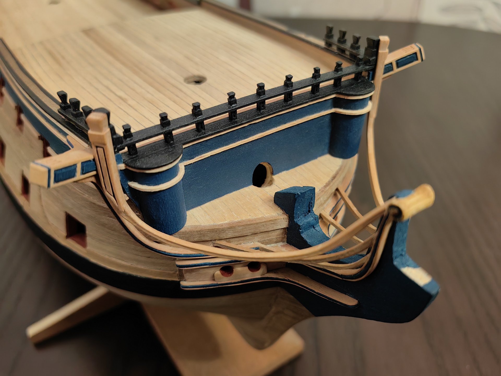
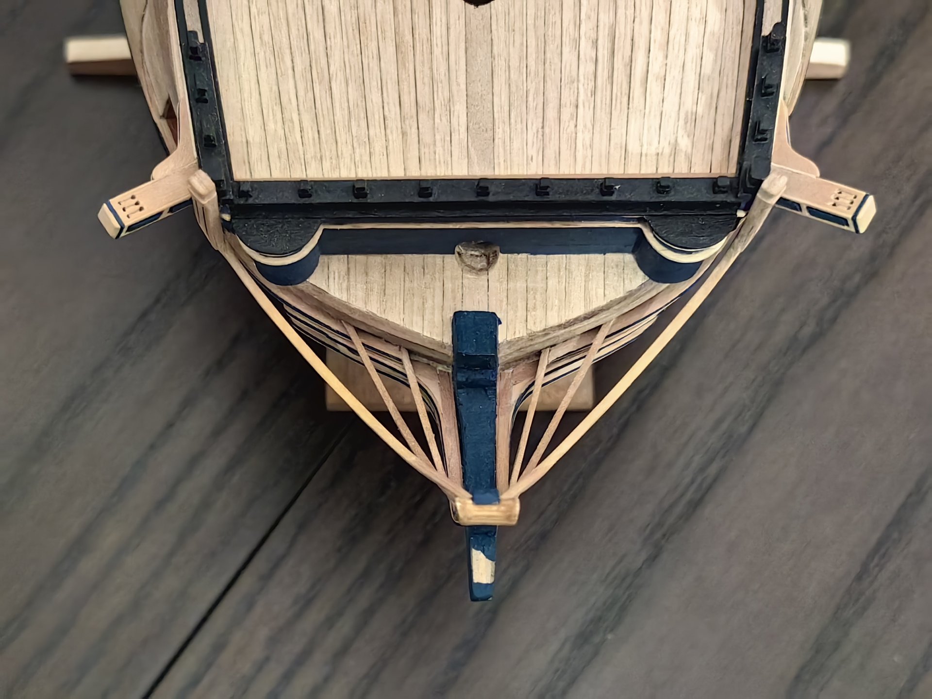
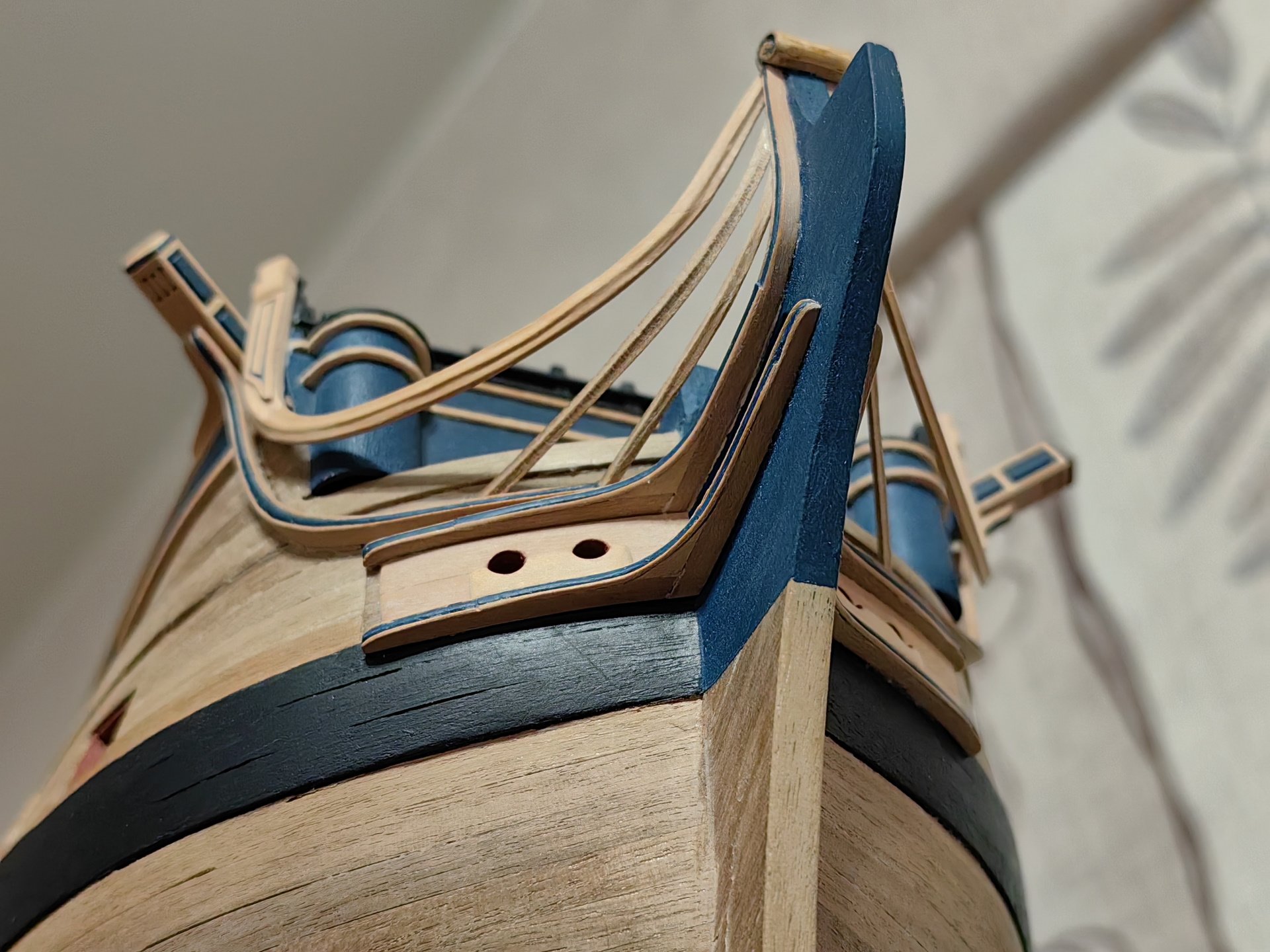
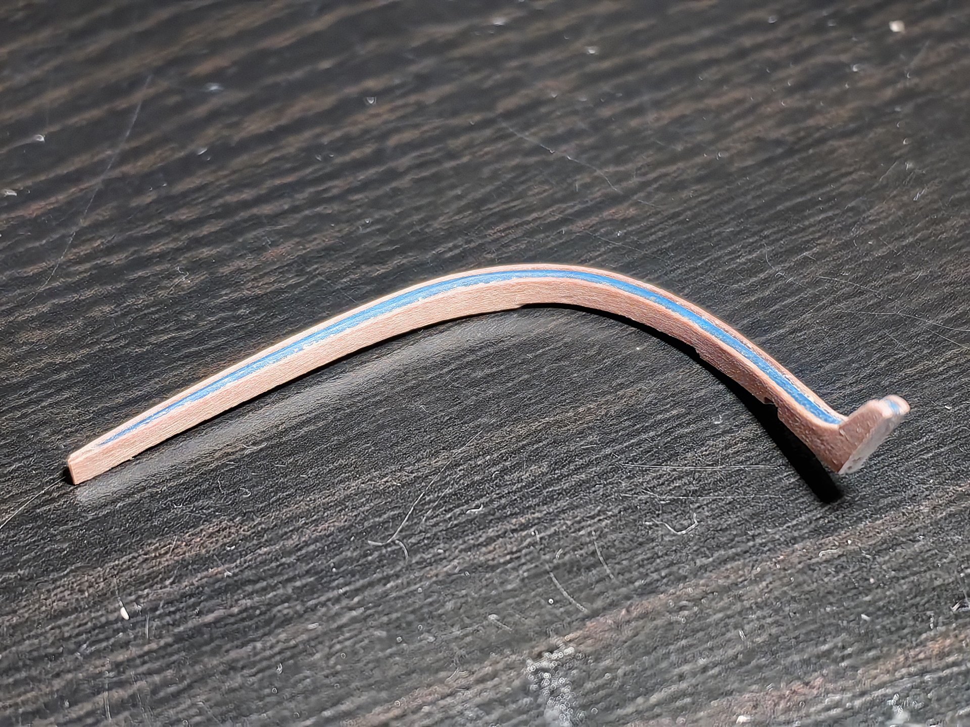
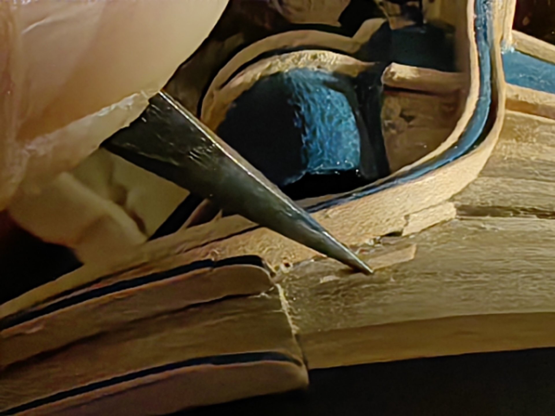
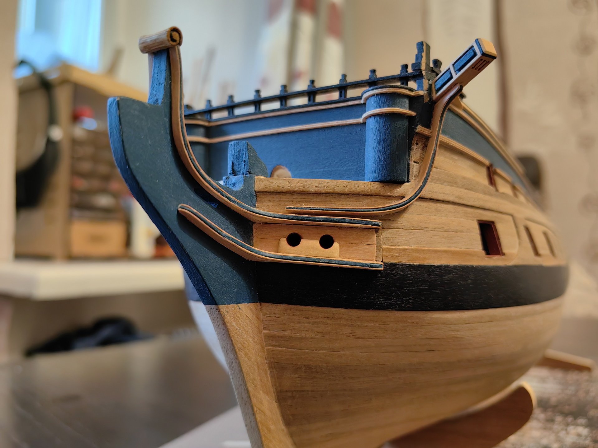
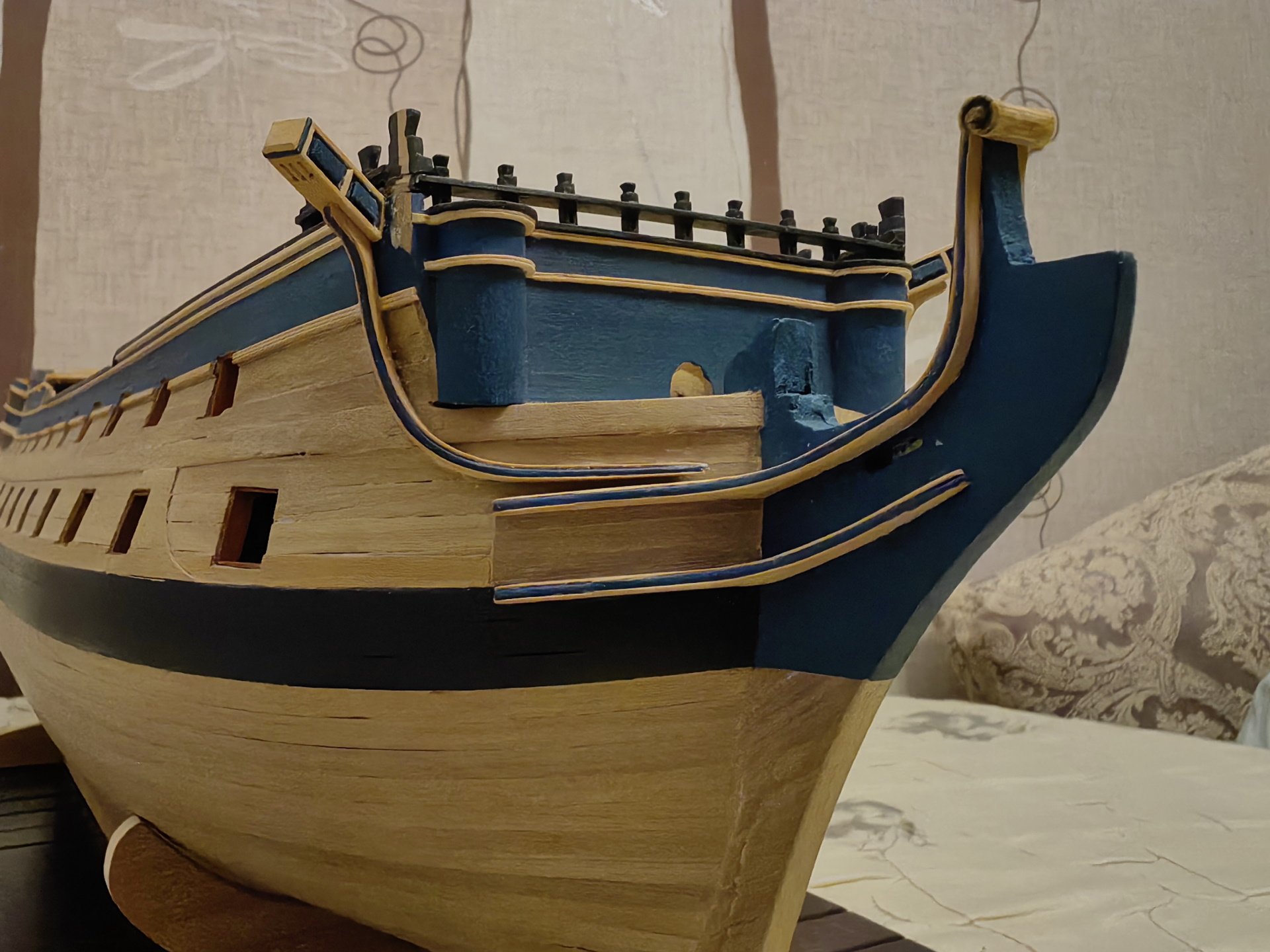
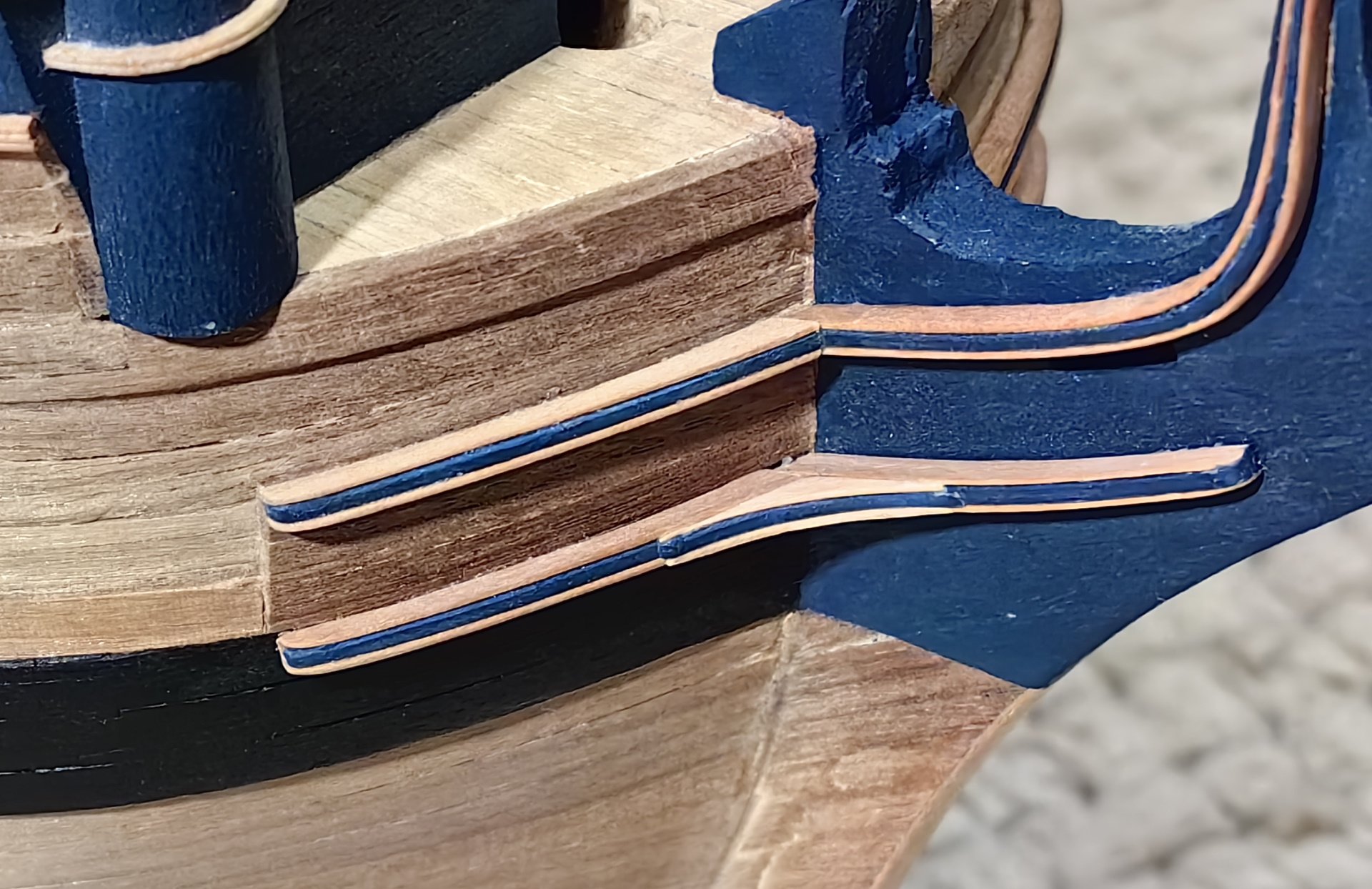
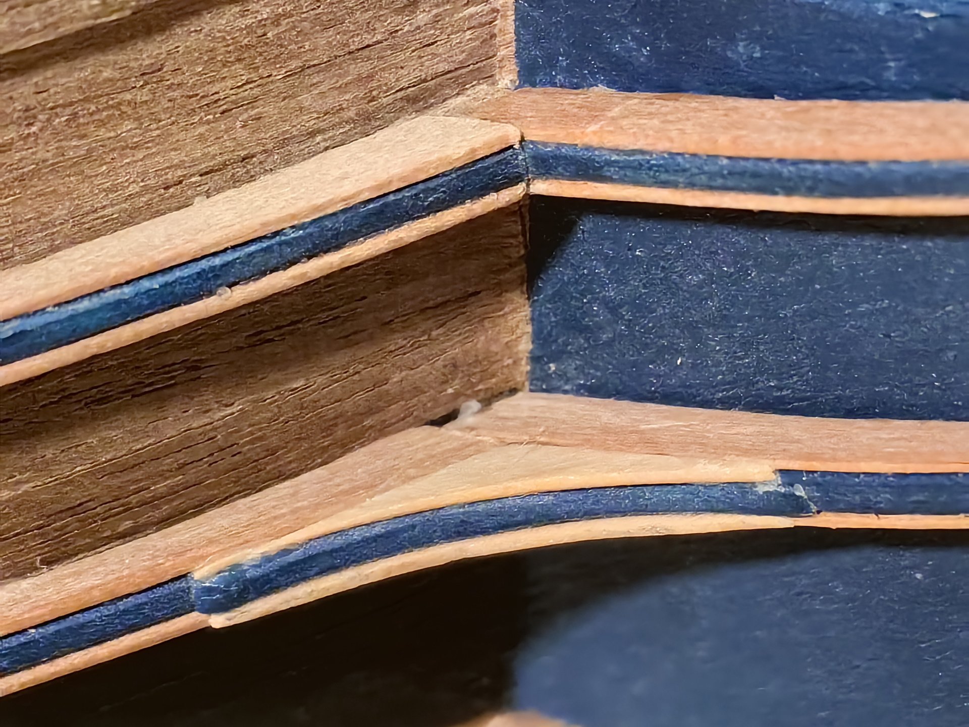
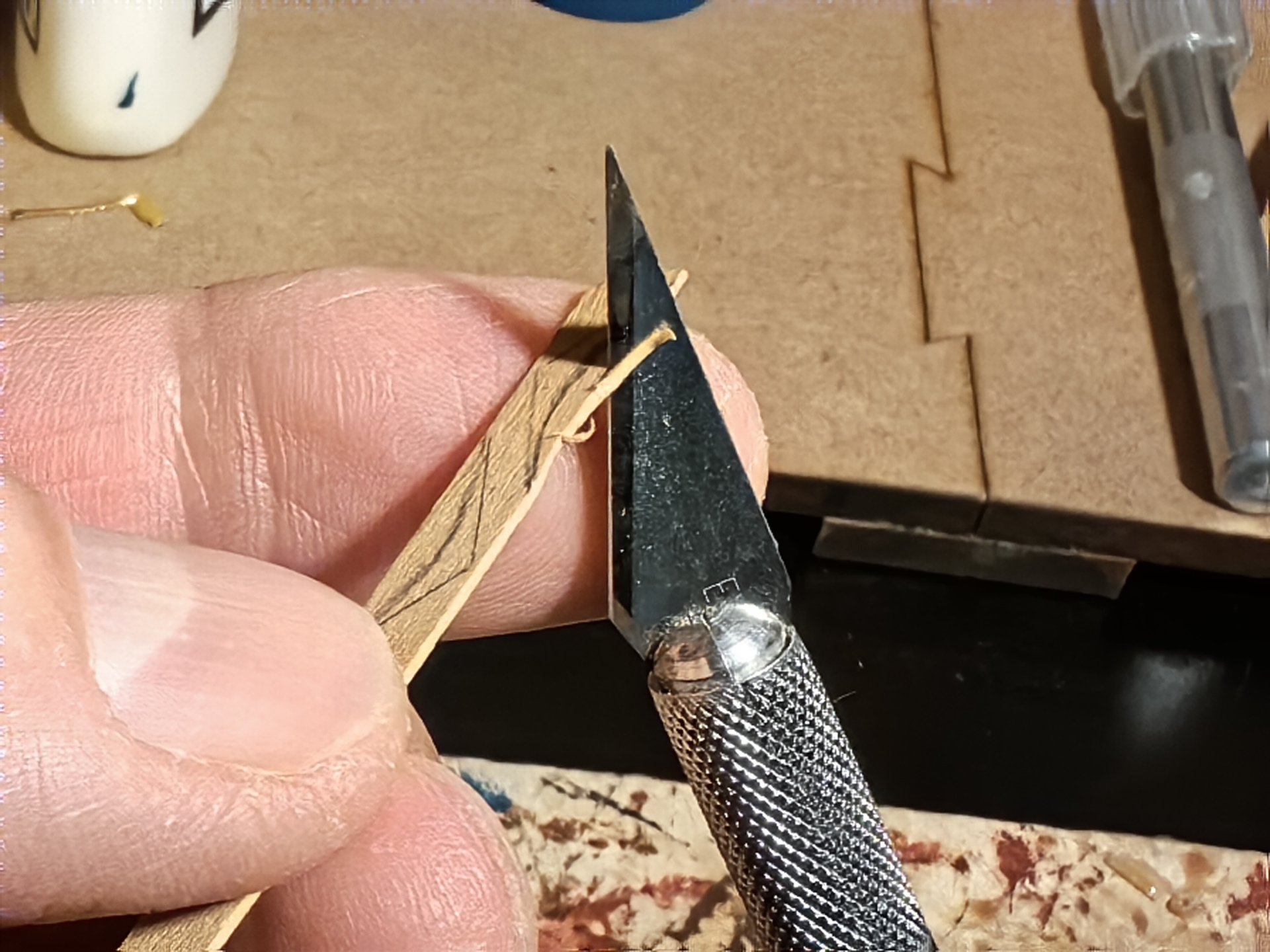
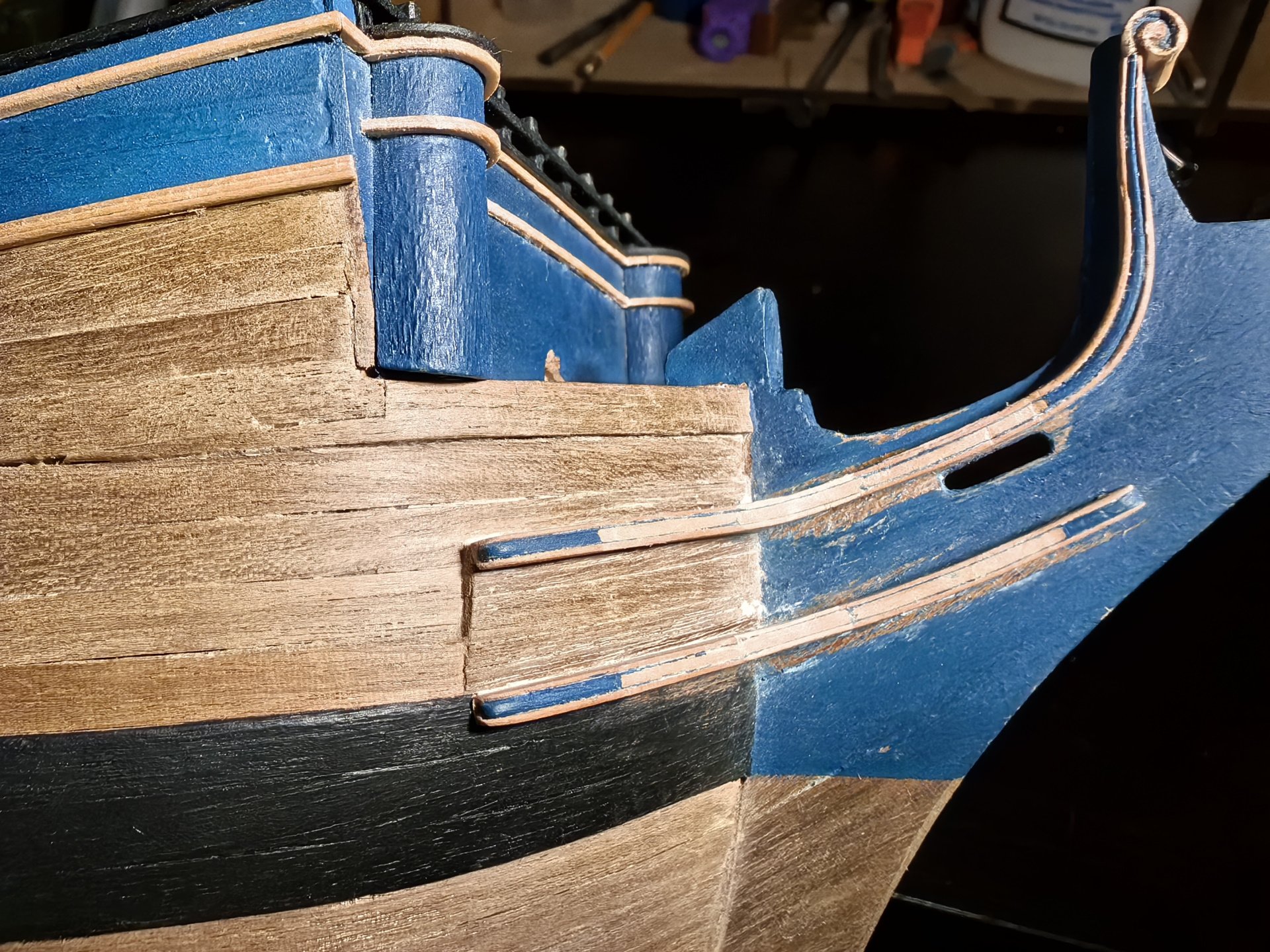
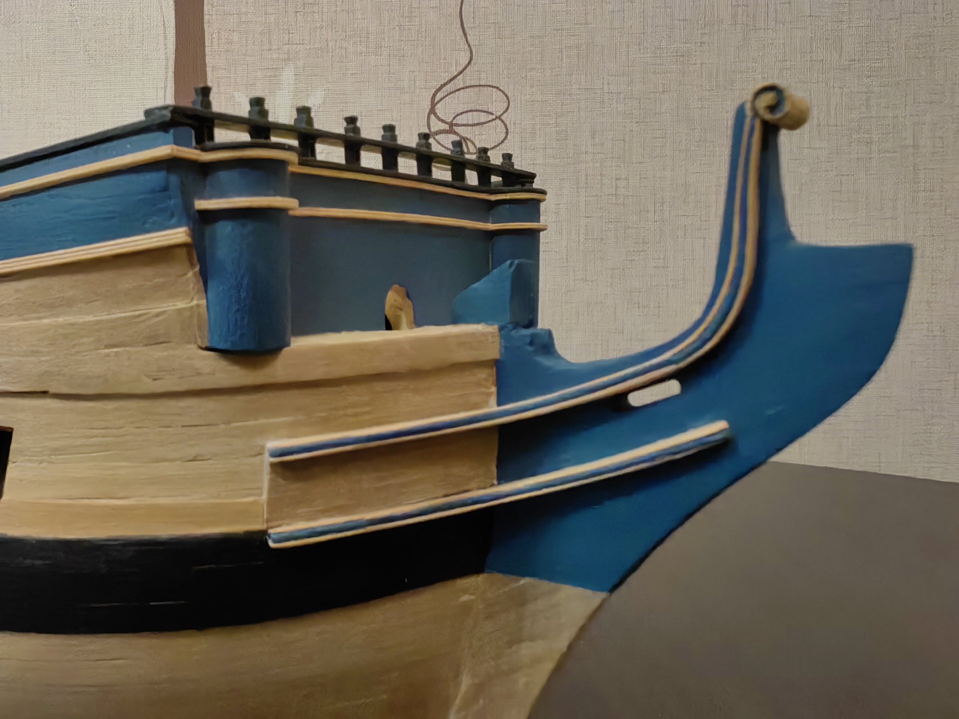
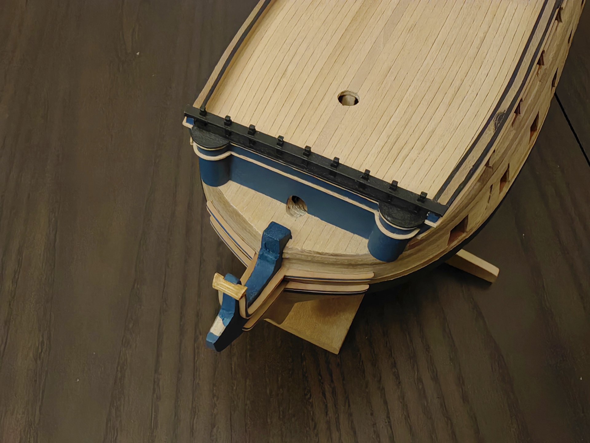
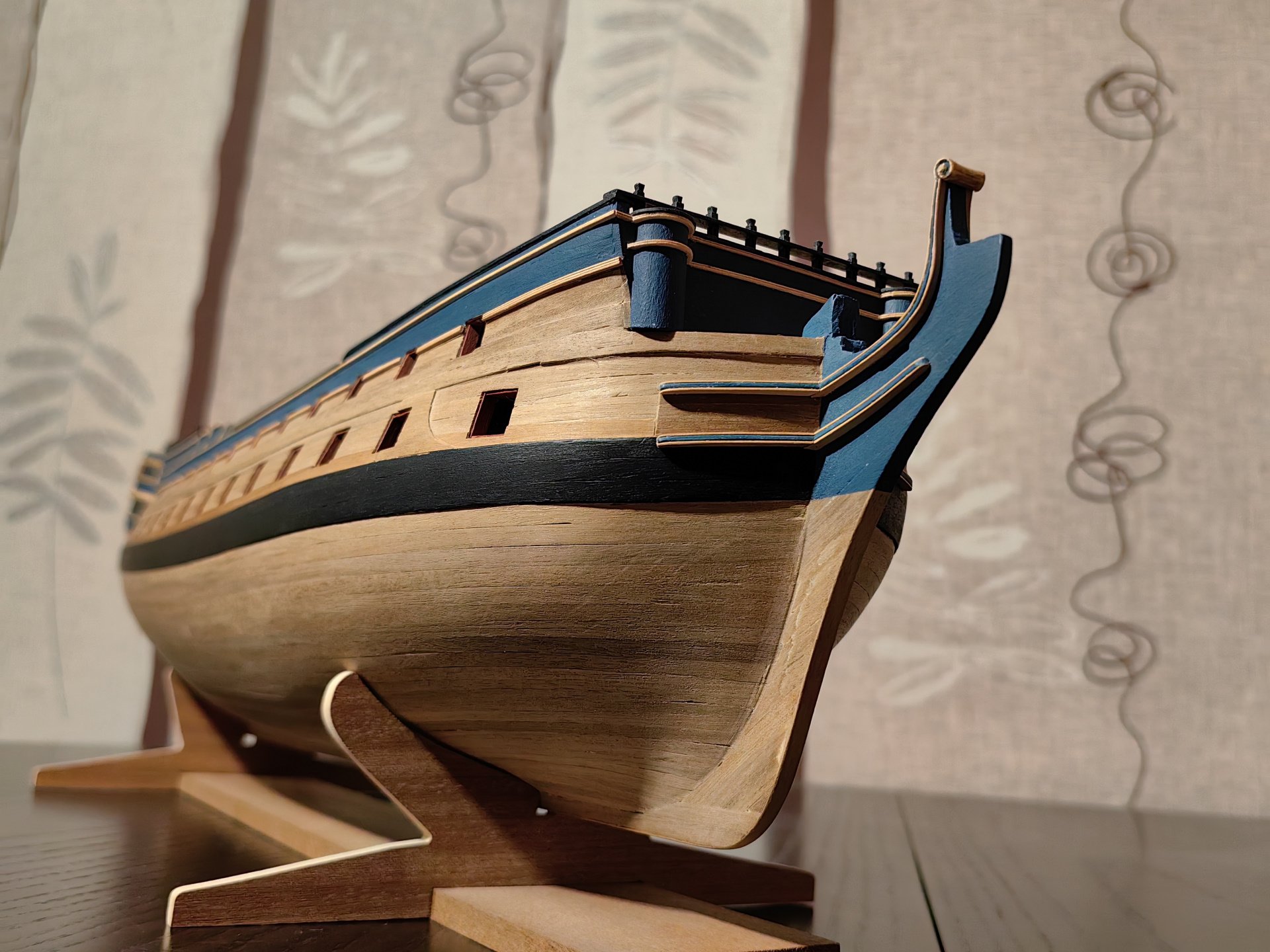
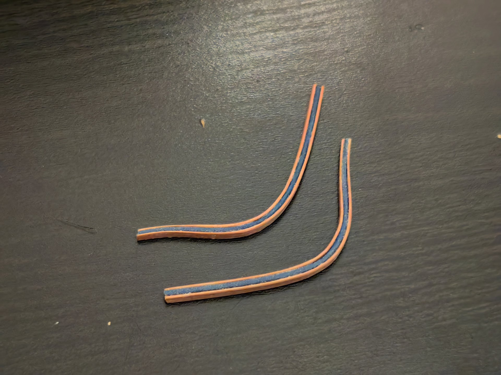
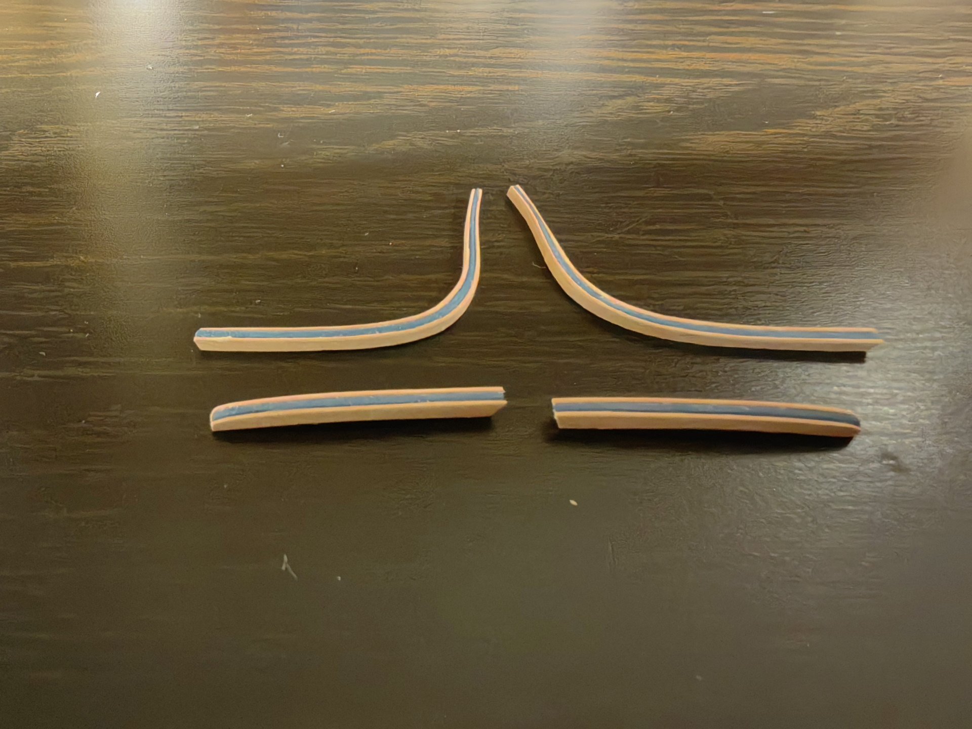
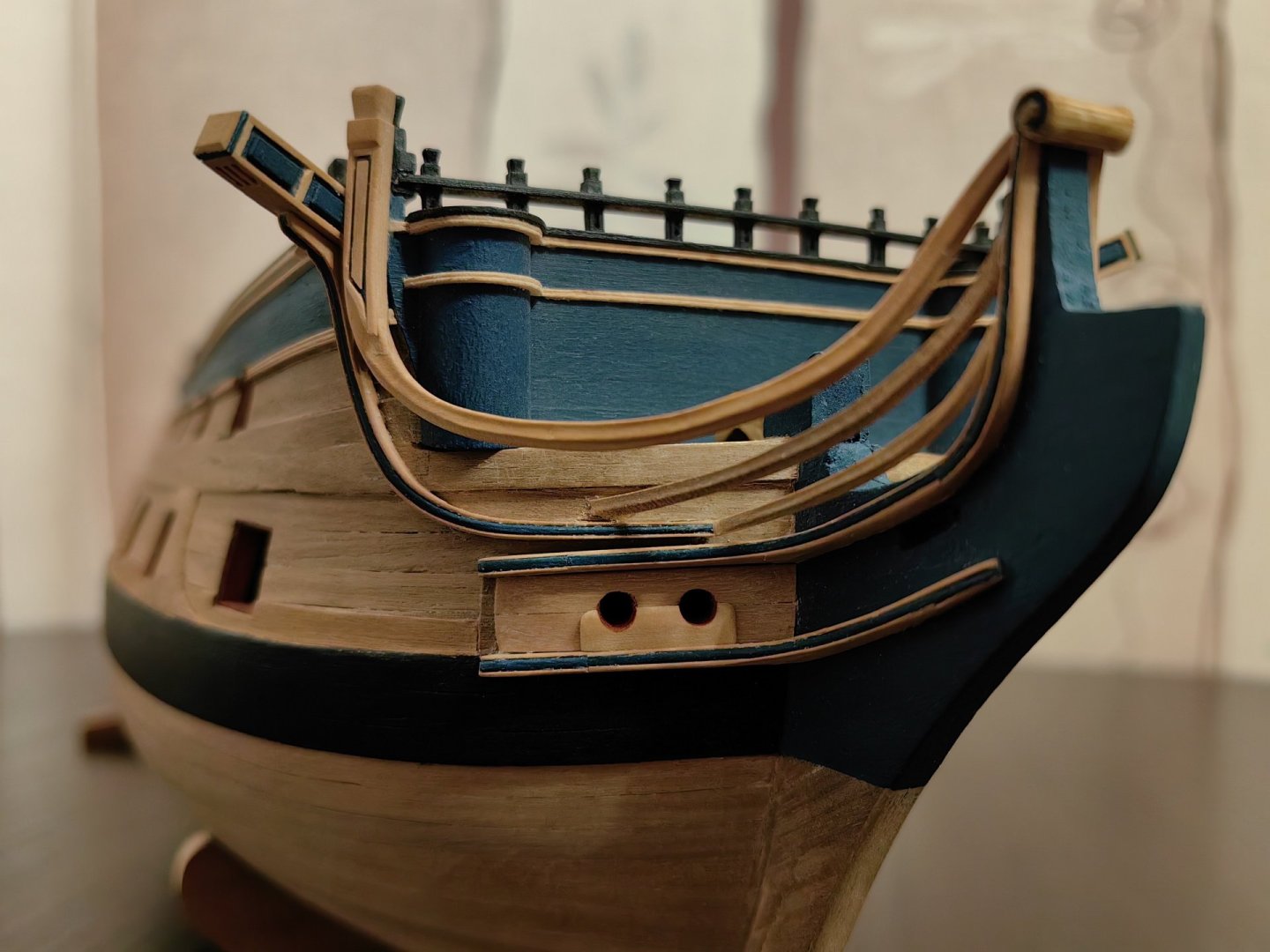
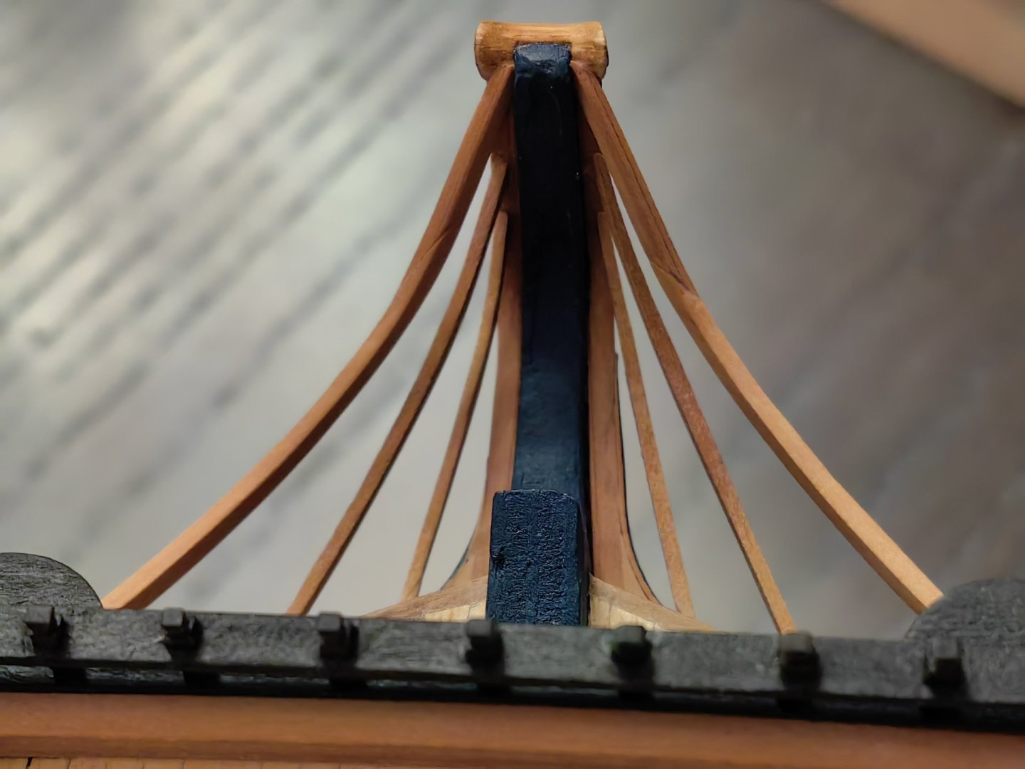
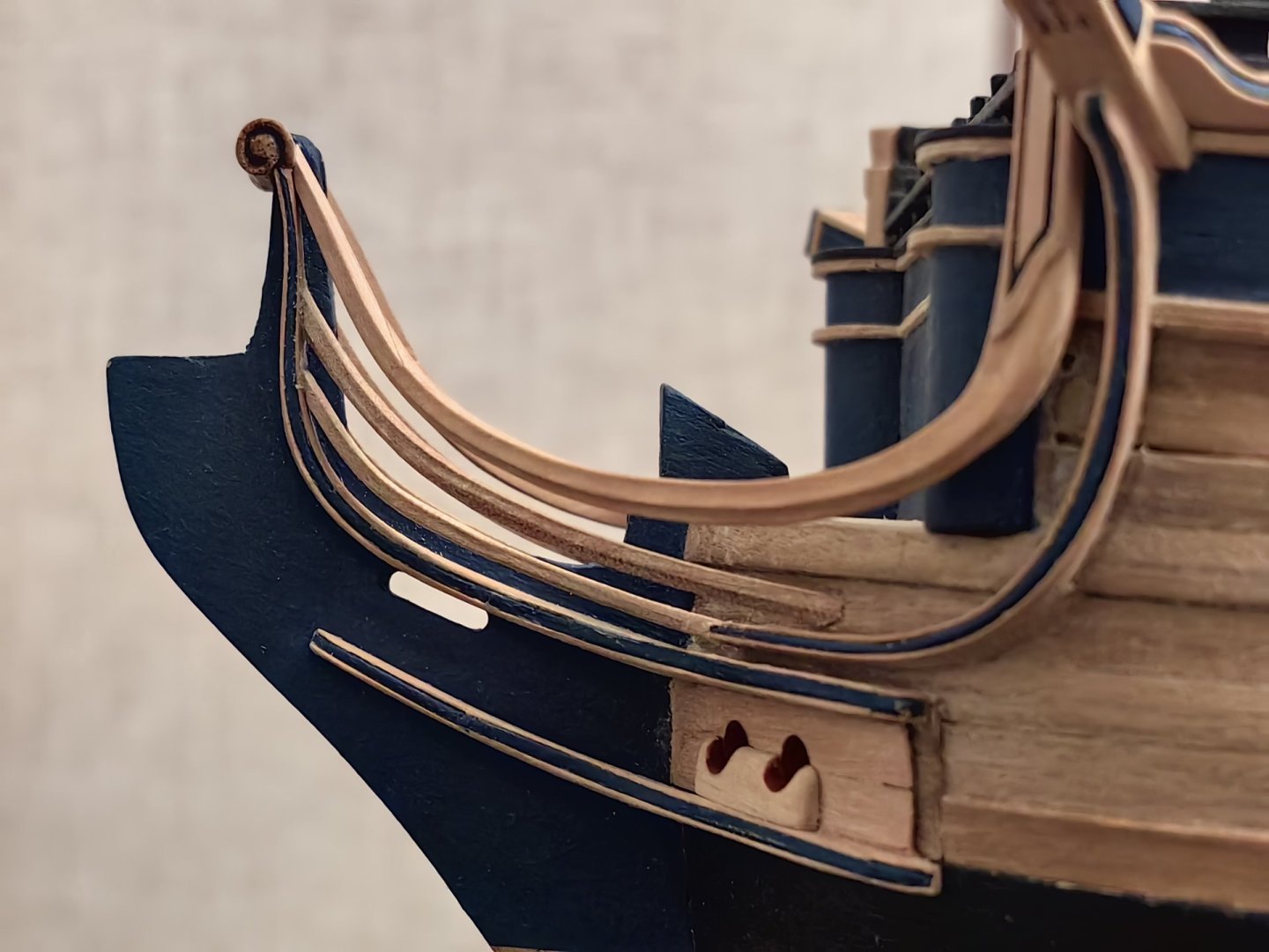
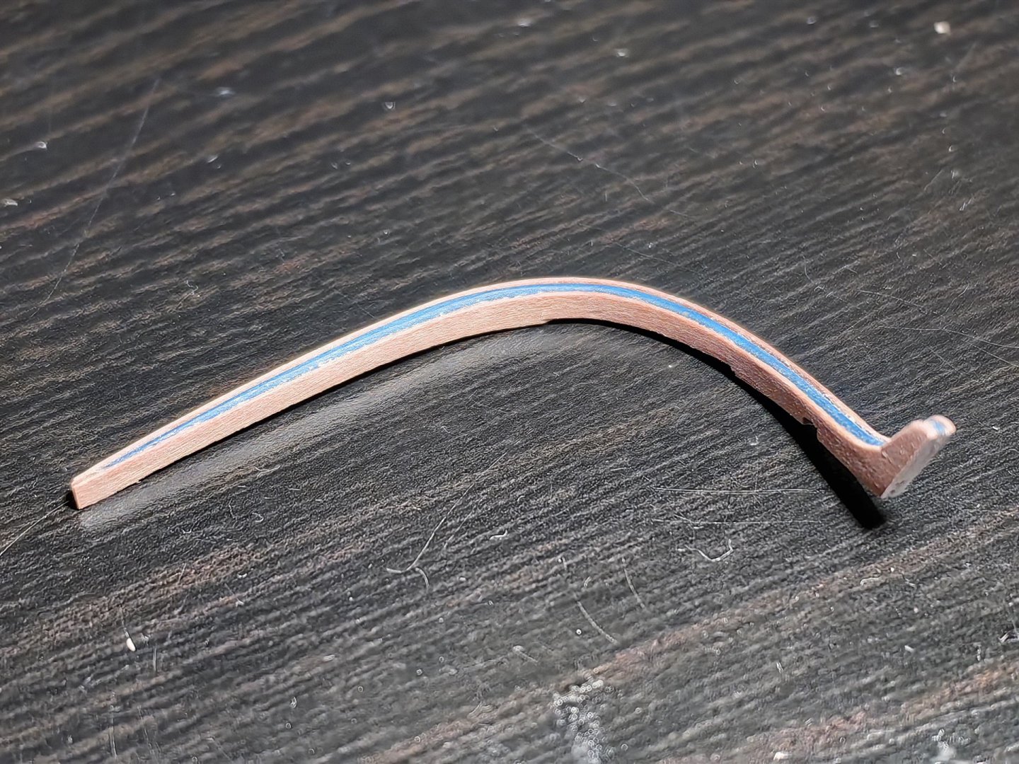
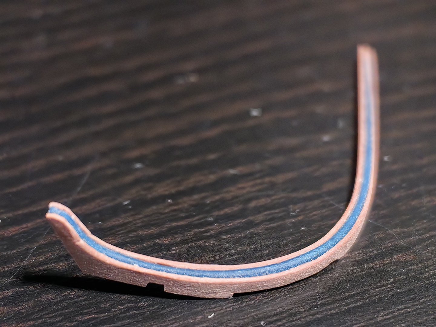
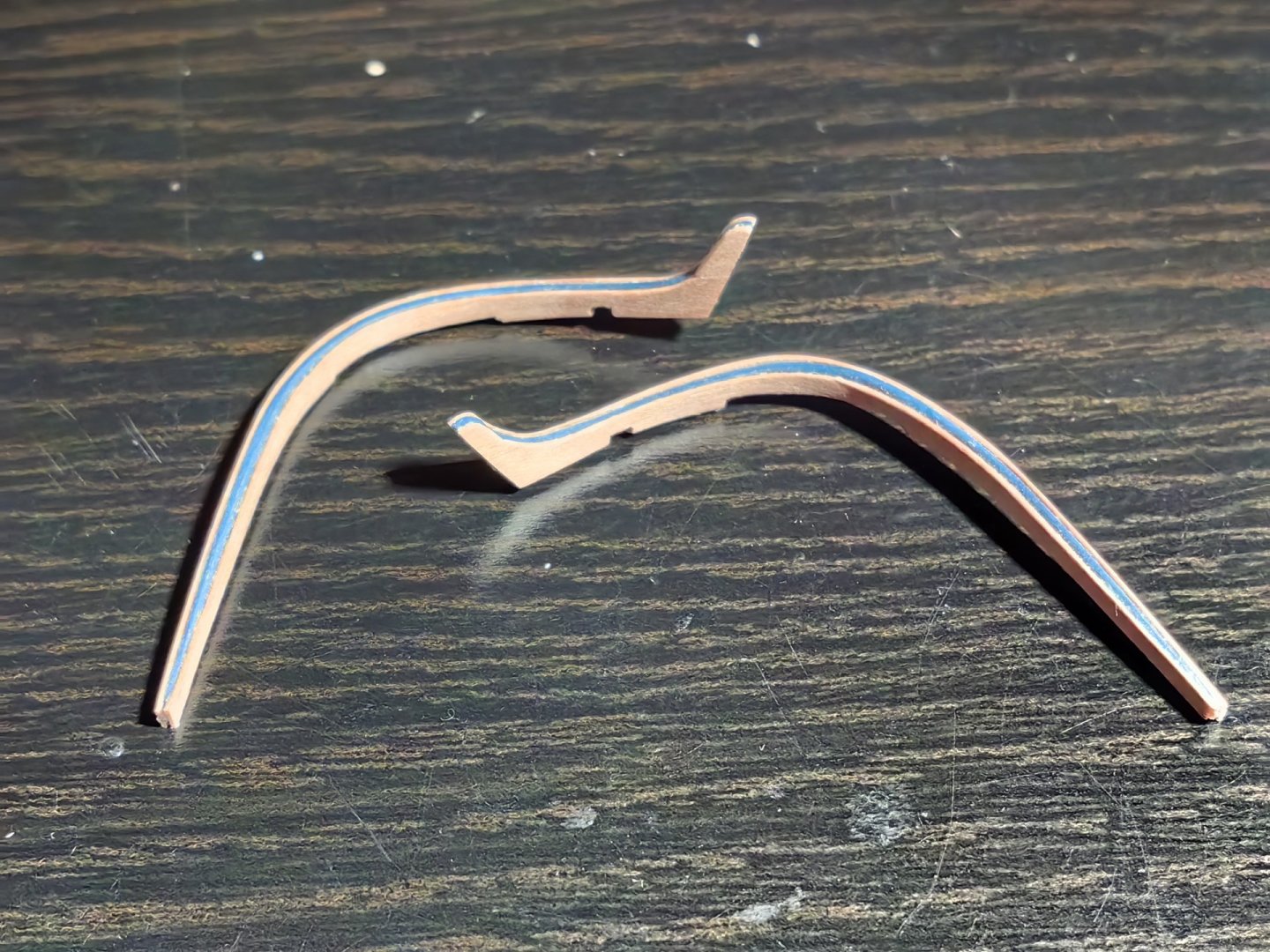
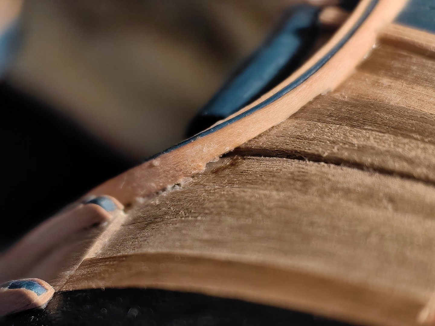
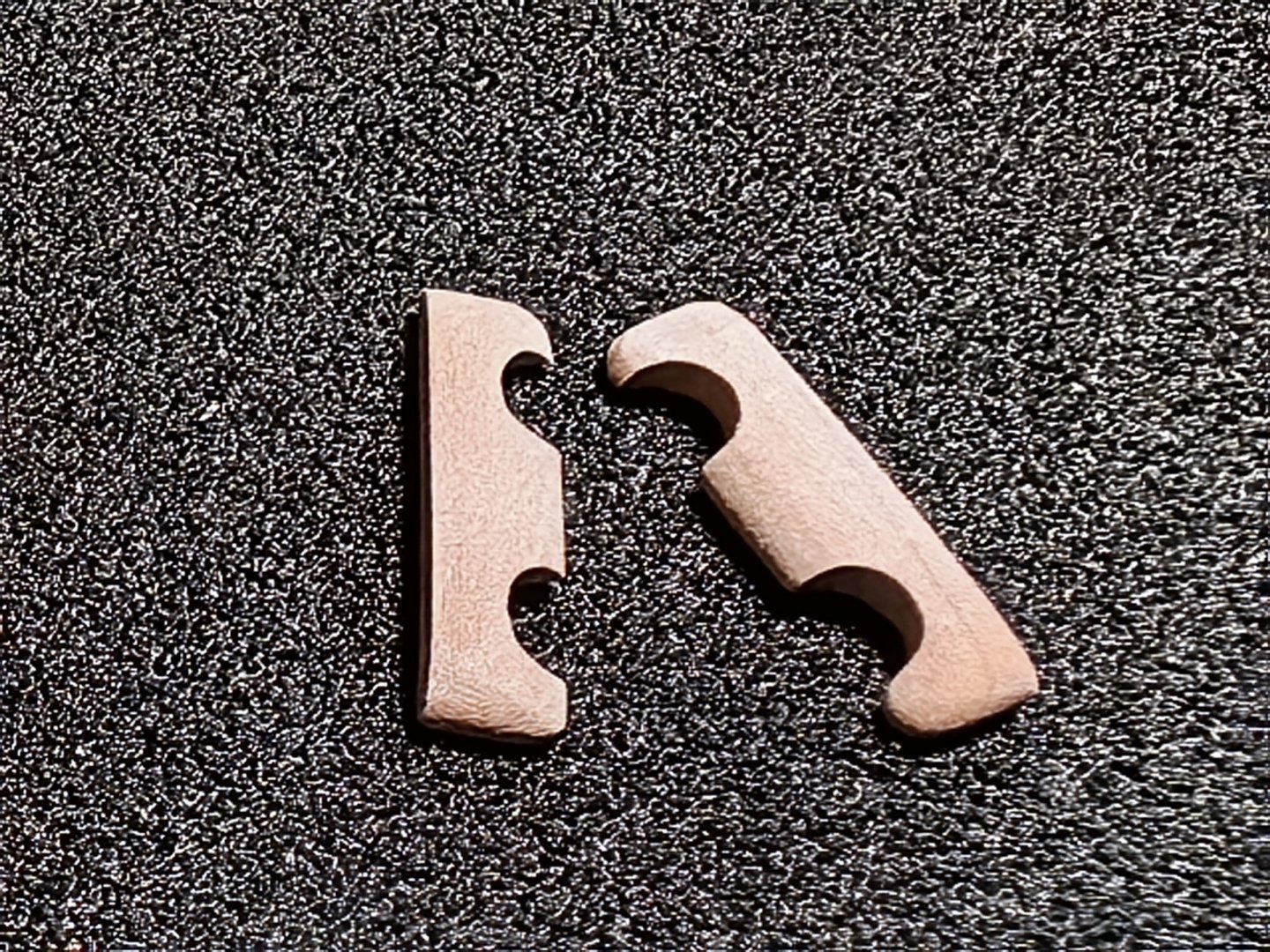
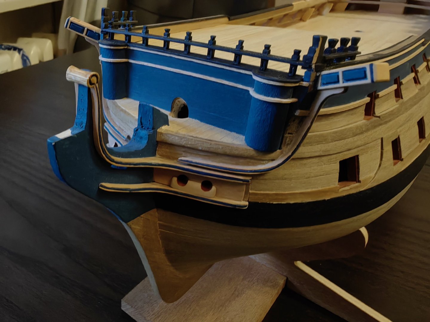
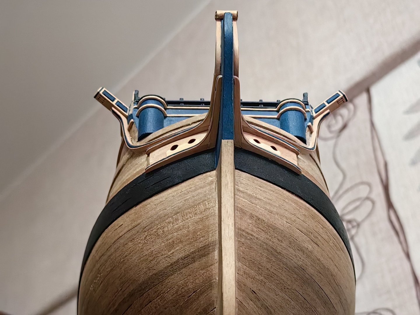
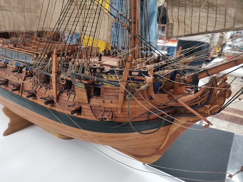
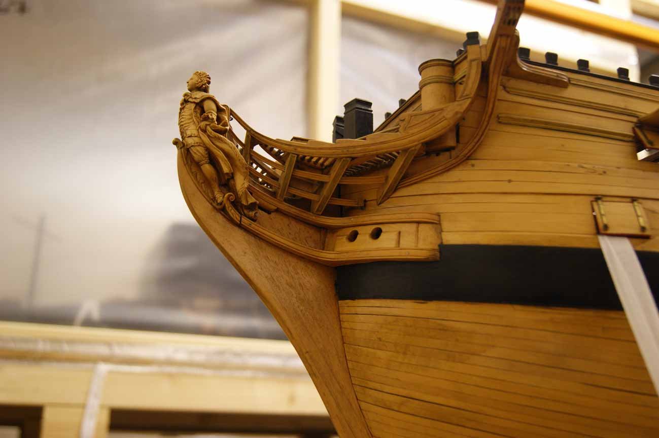
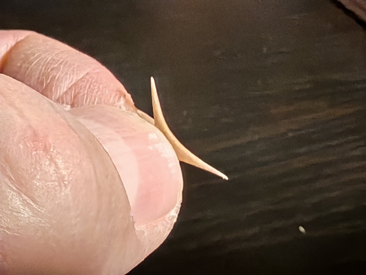
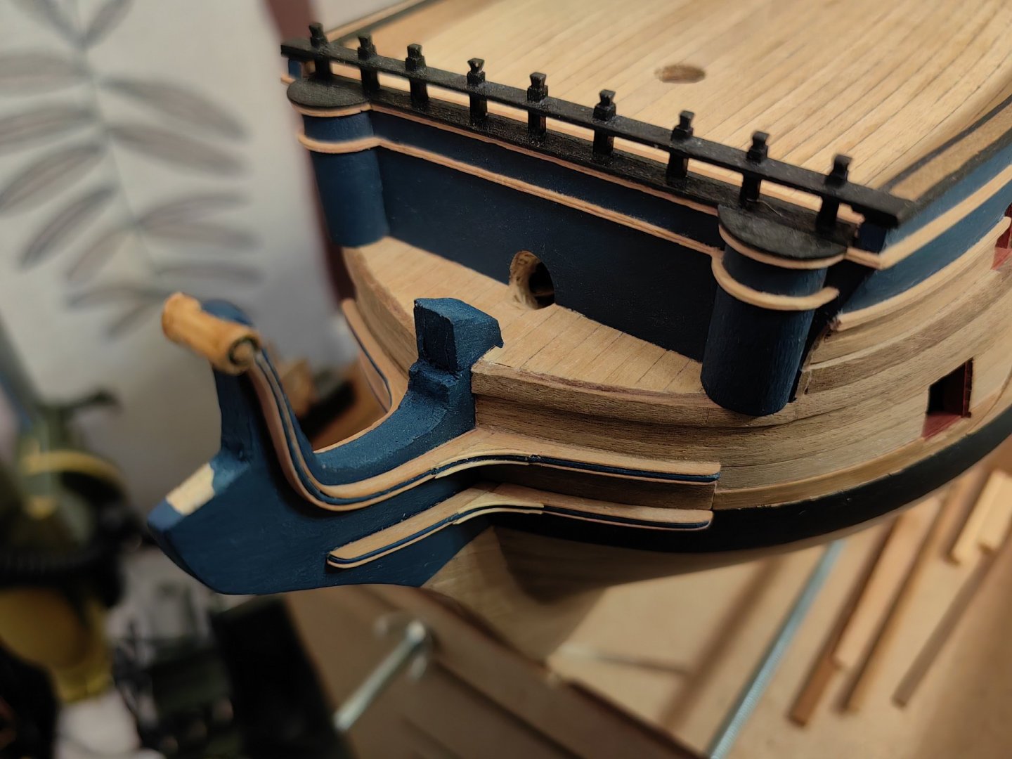
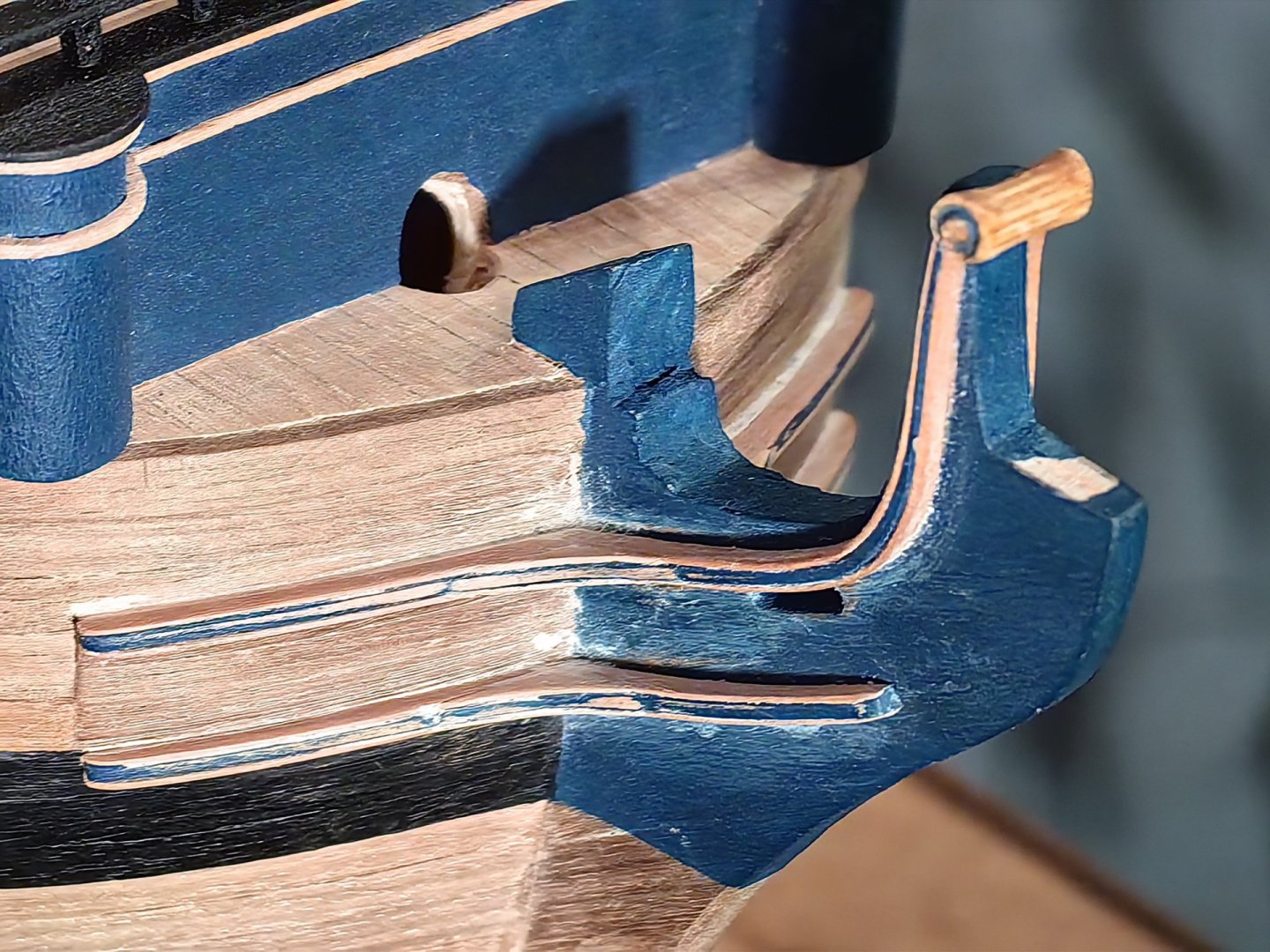
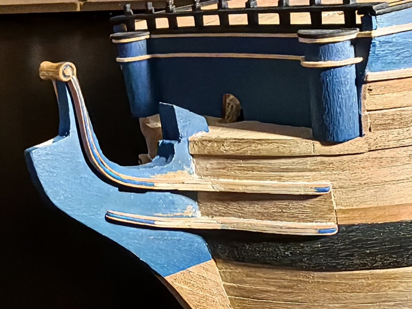
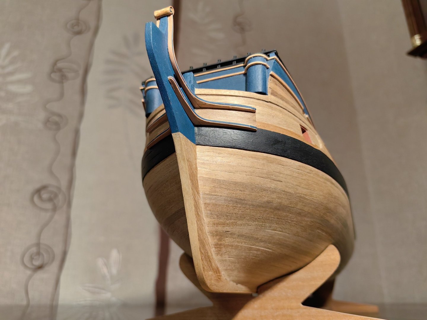
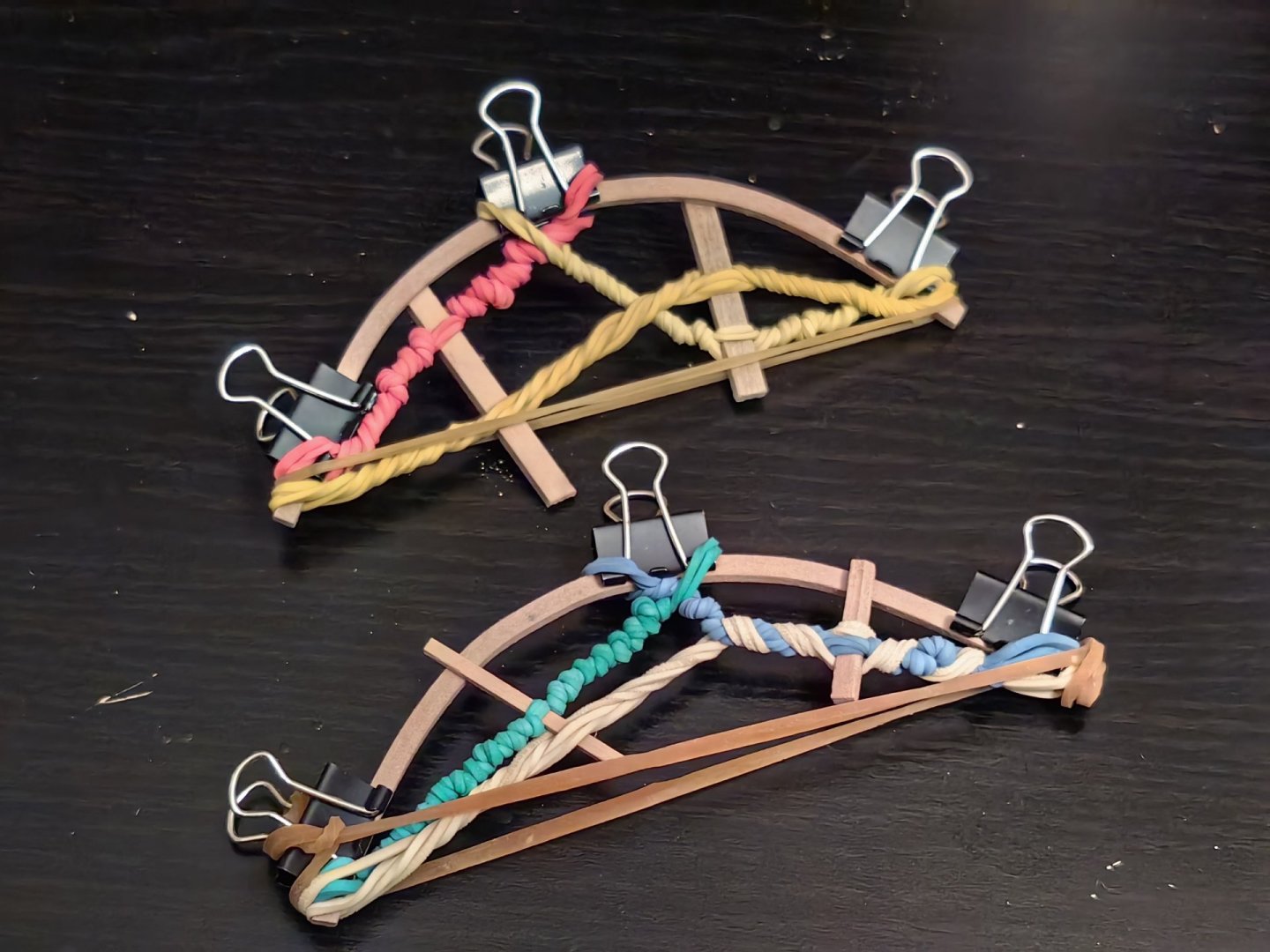
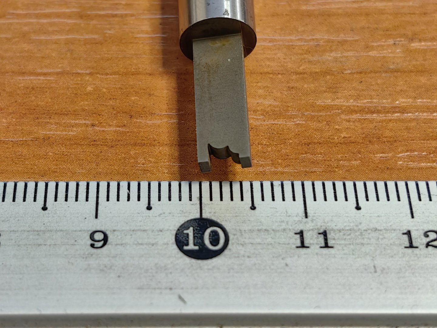
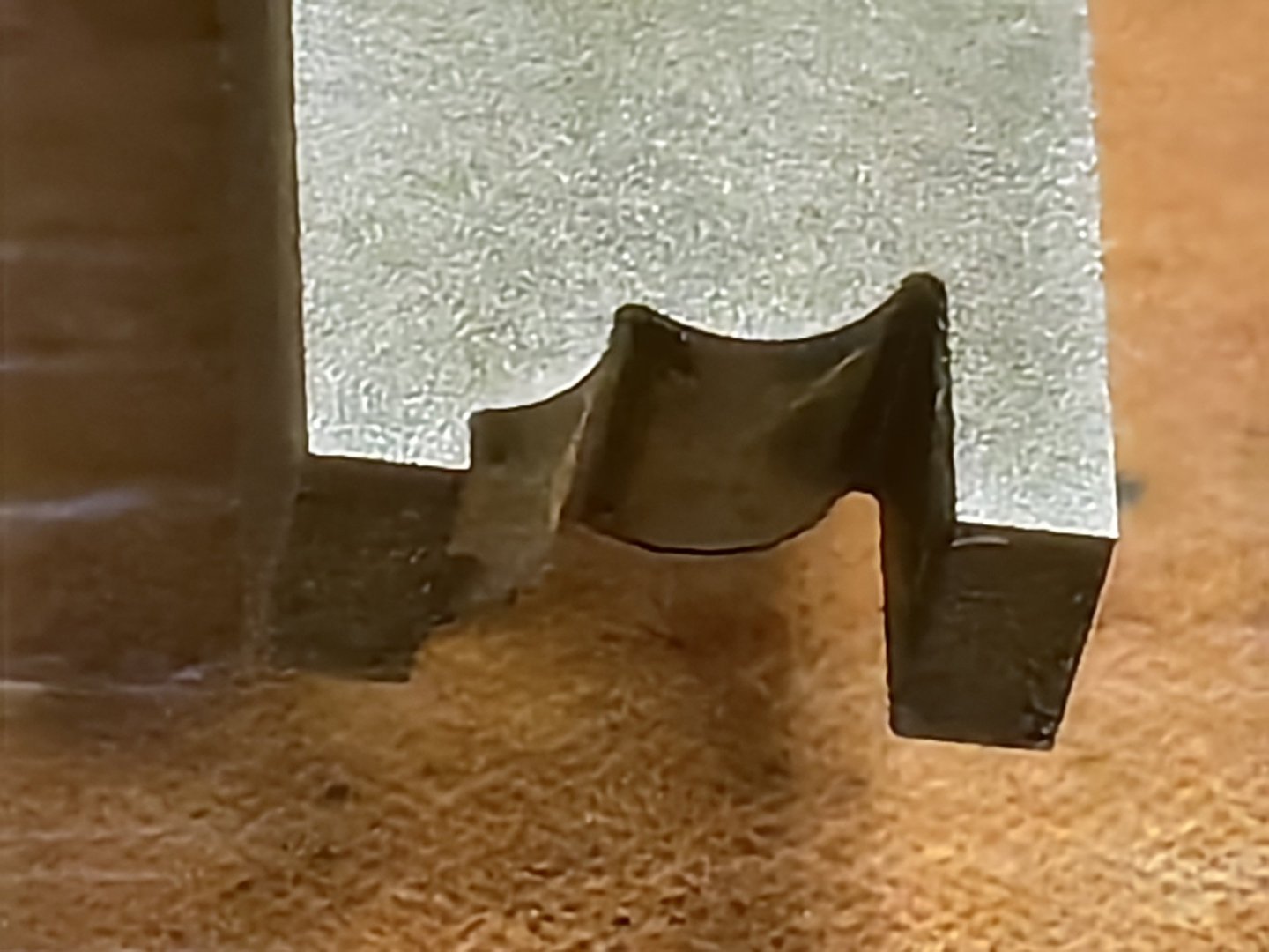
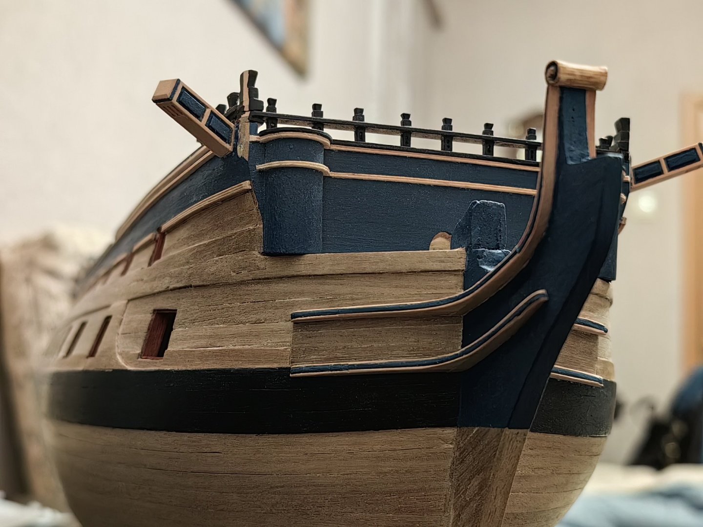
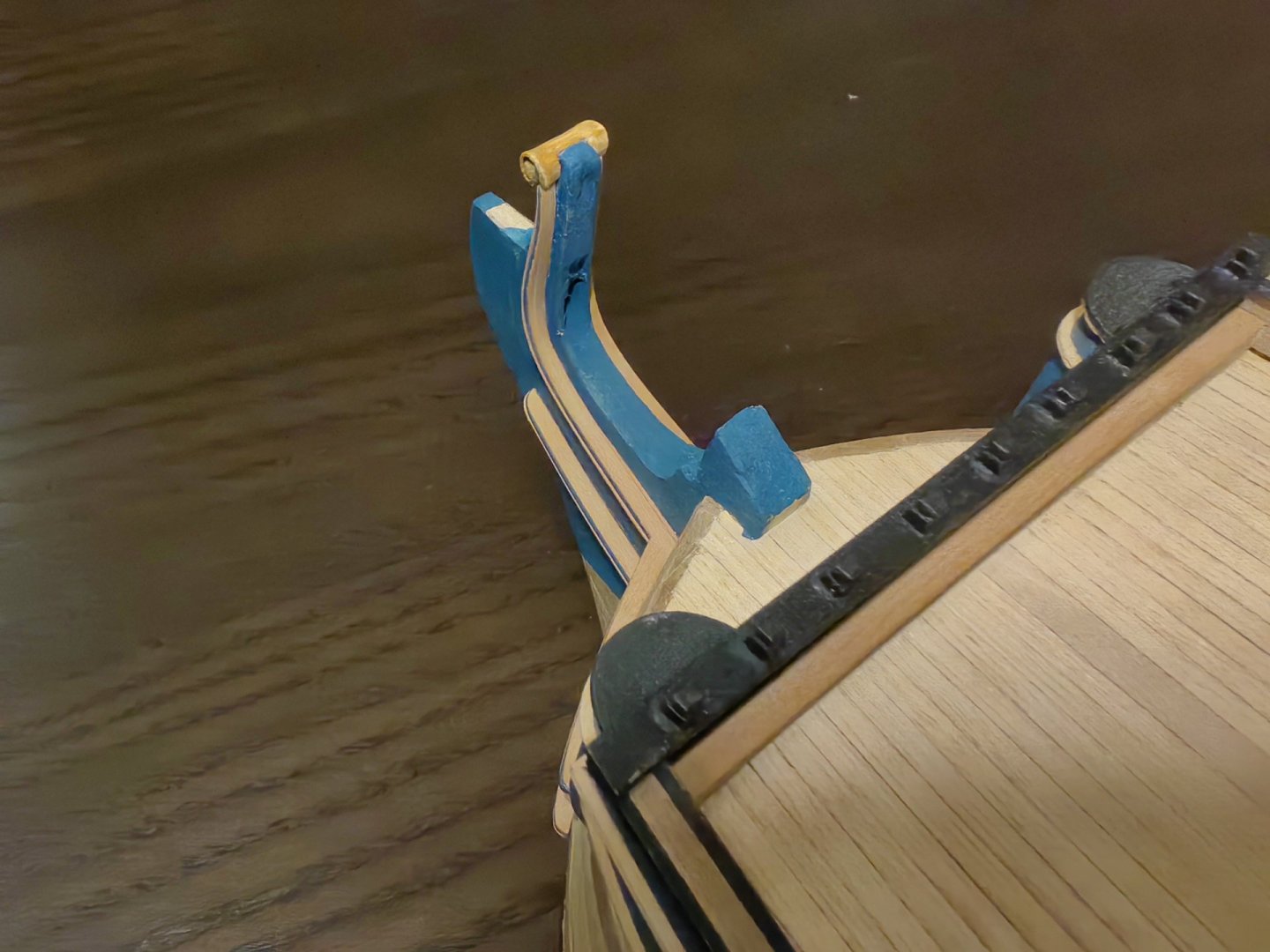
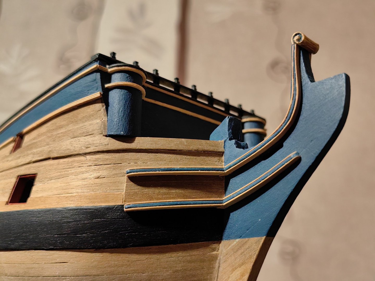
Hello everyone! I've been working on the bеakhead for the past three weeks, but it's not as easy as it seems! Since the cheeks are essentially the knees, I decided to make a thickening at their junction in the form of a separate part. And since the cheeks are glued together each of the three parts, then the details had to be made in the same way. And here I faced difficulties. The outer slats are only half a millimeter thick, and even with the most careful processing, they easily break. In addition, I tried to make the joint as invisible as possible and for this it was necessary to sharpen the tips almost to zero. In general, I broke an uncountable number of them. Although the joints were still visible, I decided to stop there. But after that, I decided to fill in the gaps where the cheeks were attached to the body with acrylic wood-colored putty, which I had purchased specifically for this purpose. However, I made a mistake. I was not careful enough when applying the putty, and it ended up covering the entire nose of the model. When the putty dried, it turned out to be almost white, and it got trapped between the three parts of the cheeks, making it impossible to remove. I managed to remove the putty from the smooth surfaces, but I couldn't remove it from the cheeks without removing the paint from the middle rail. After that, I couldn't paint it without getting the adjacent areas dirty. I didn't want to redo the cheeks, so I decided to make a compromise. I cut off the damaged part, made a 0.5 mm thick edge from three pieces of wood, and glued it to the cheeks. It wasn't as beautiful as it was before the putty, but it was still passable. Then I had to touch up the head knee and chainwales This is the result. The next step was to make the main rail. At first, I tried to bend a 2x4 mm rail according to the profile on the drawing. I steamed it in boiling water, bent it with an iron, and then soaked it again in boiling water, holding it with rubber bands to prevent it from straightening. However, it didn't work out. The curve was too sharp, and the rail broke. In the end, I cut the central part of the main rail from a 20 mm wide rail and glued the ends. On prototypes and museum models, these rails have a beautiful carved profile. To give the rails a similar profile, I made a tool similar to the one used to profile the rails along the sides. However, the main rail gradually narrows from 4 to 2 mm, while the tool's profile width is 3 mm. Additionally, since the part was cut from a wide rail, the tool sometimes cuts across the layers, resulting in poor initial quality of the profile. A round file and sandpaper solved this issue. This is what I ended up with. The top timbers on the main rail should fit snugly against the top timbers on the bulkhead of the beakhead, which is painted black. It might be a good idea to paint it black as well, but on the Charles Middleton’s model, represented in the museum it's painted by wood color and looks good. I decided not to paint it yet and see how it looks when assembled. If there are any issues, I can always color it up later. I'm not entirely sure about the best order to assemble the beakhead. I think that I will first make all its parts and then assemble the whole structure. In the meantime, as a reference point, I decided to use the cathead, which I made from a beech 4x4 mm rail, pasted with a 0.5 mm rail from a pear tree and installed them on the body.


-
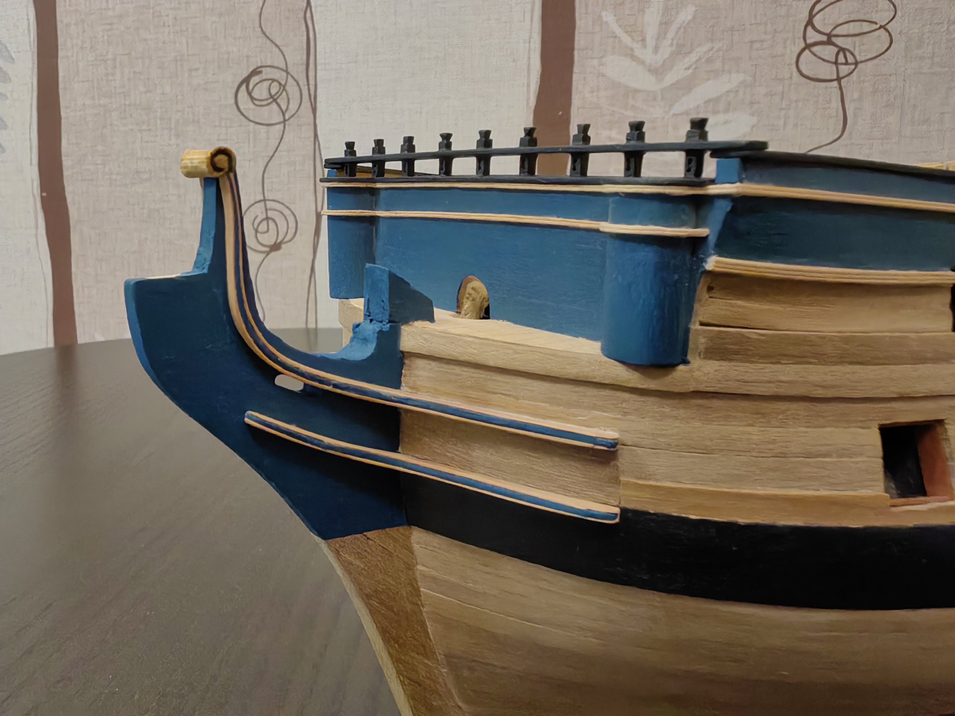
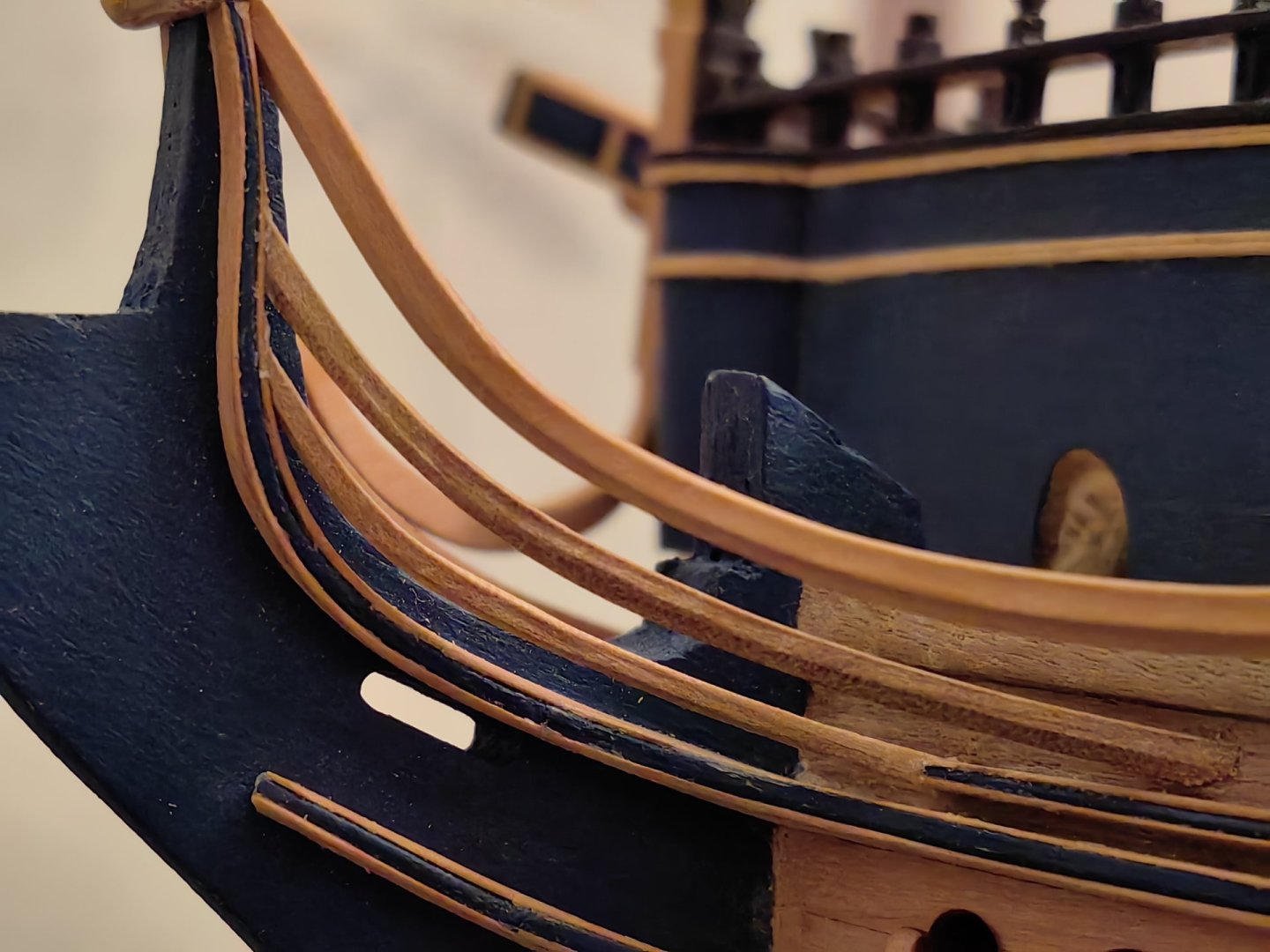
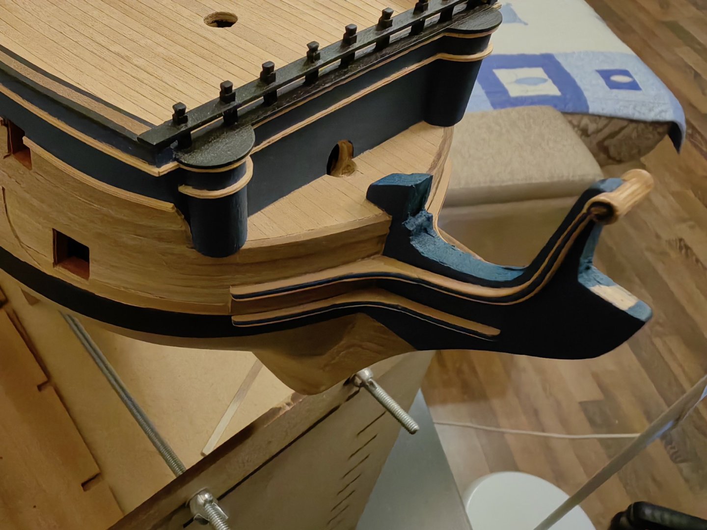
Hi! The assembly of cheeks from several parts did not take much time. Unexpectedly, a lot of it was spent on fitting and mounting them on the hull. And this is the result. Probably not perfect, but, as I think, no worse than everything else. Here, of course, there will be something to finish. Since on the prototypes, cheeks have a smooth transition from the hull to the head knee, and I just have them docked, I want to make something like knees with an internal radius. There are also some gaps that need to be seal. In general, this process is endless. But the result is satisfying)


-
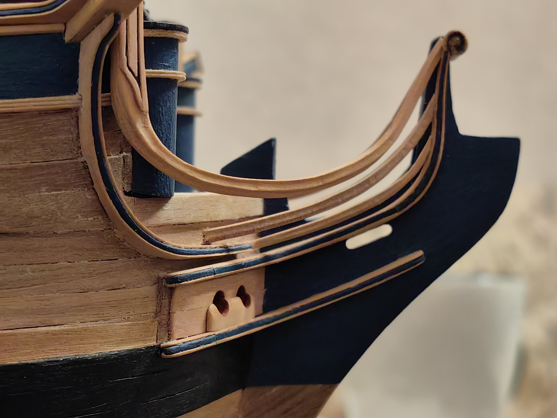
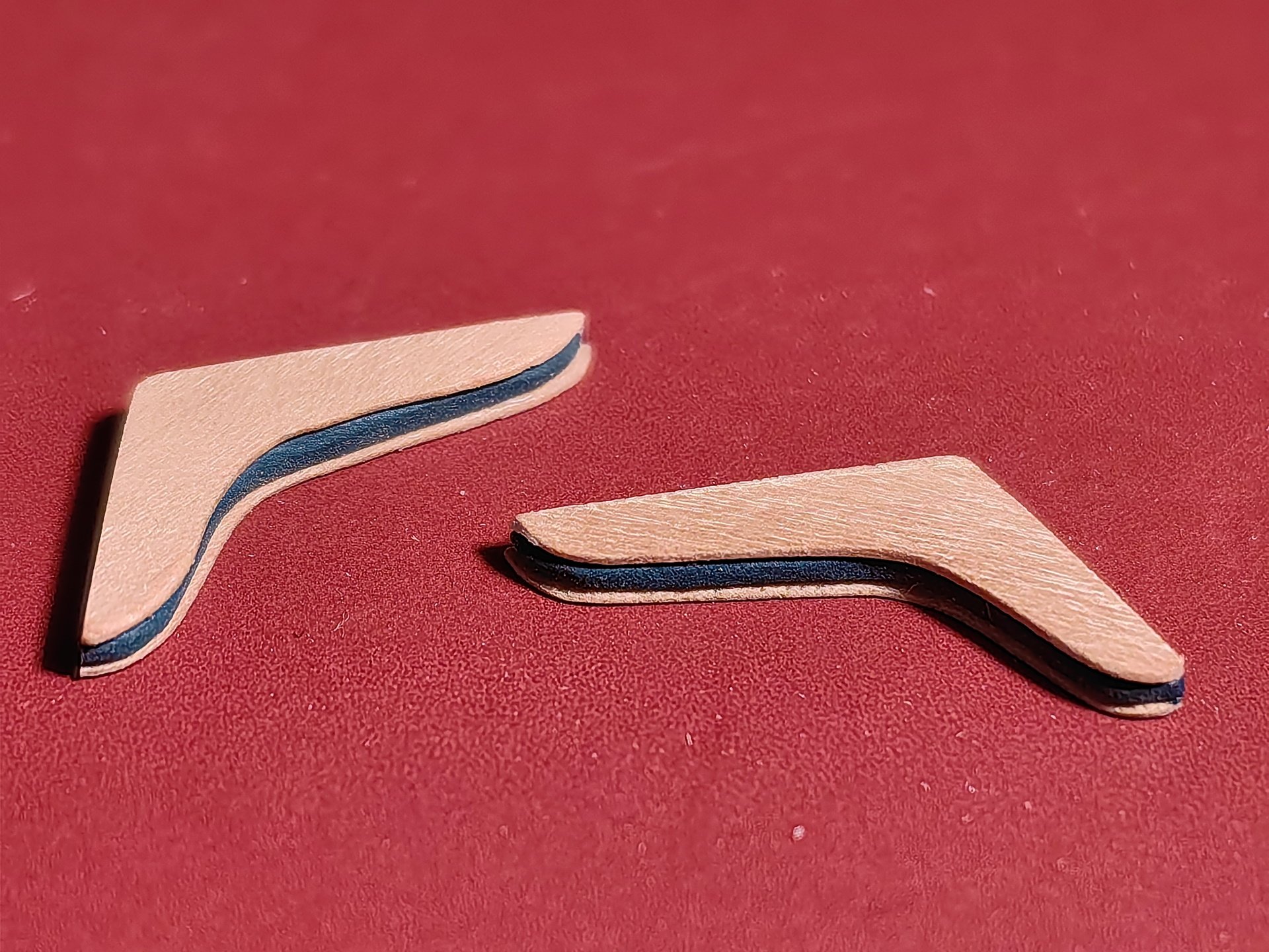
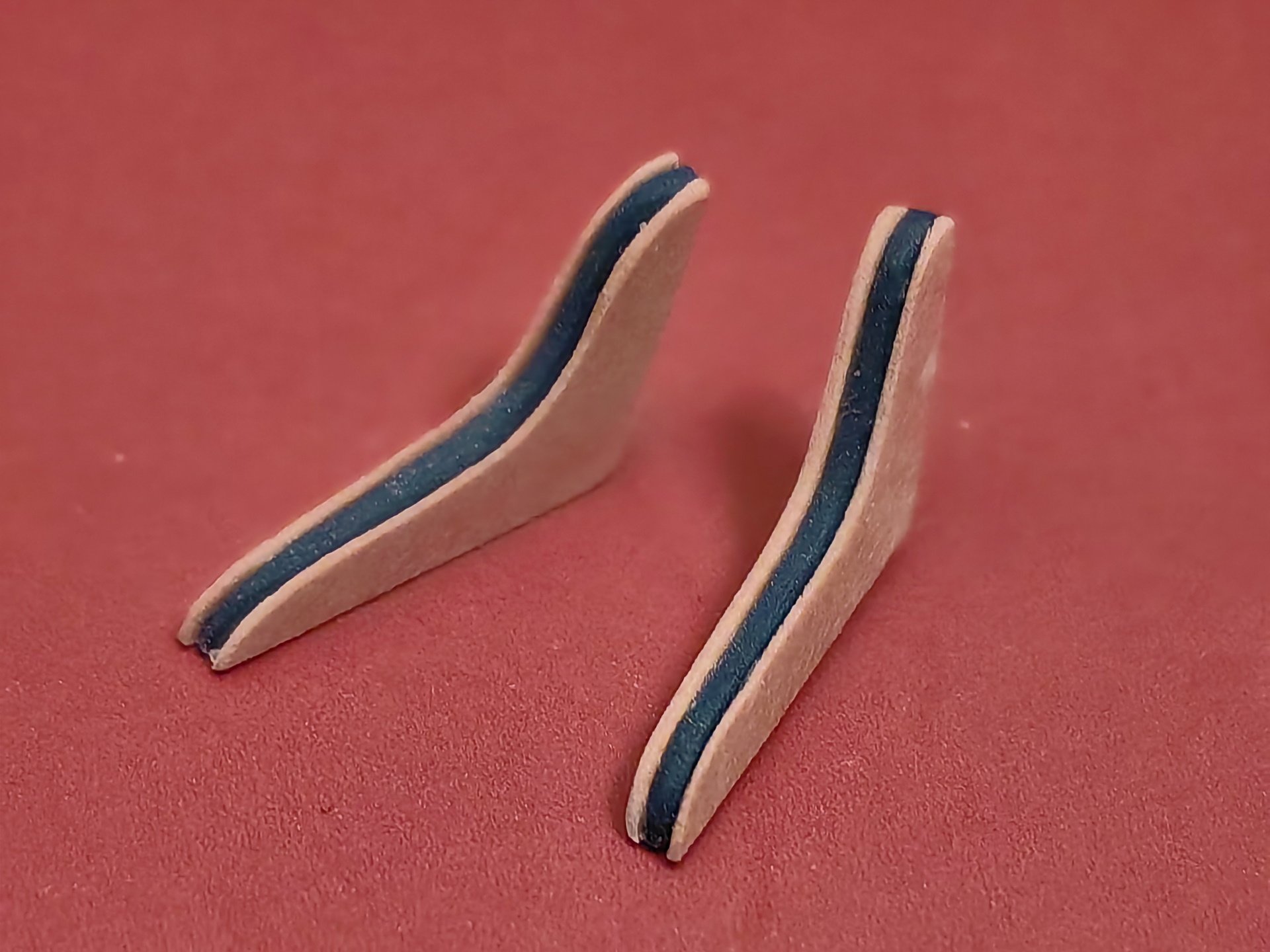
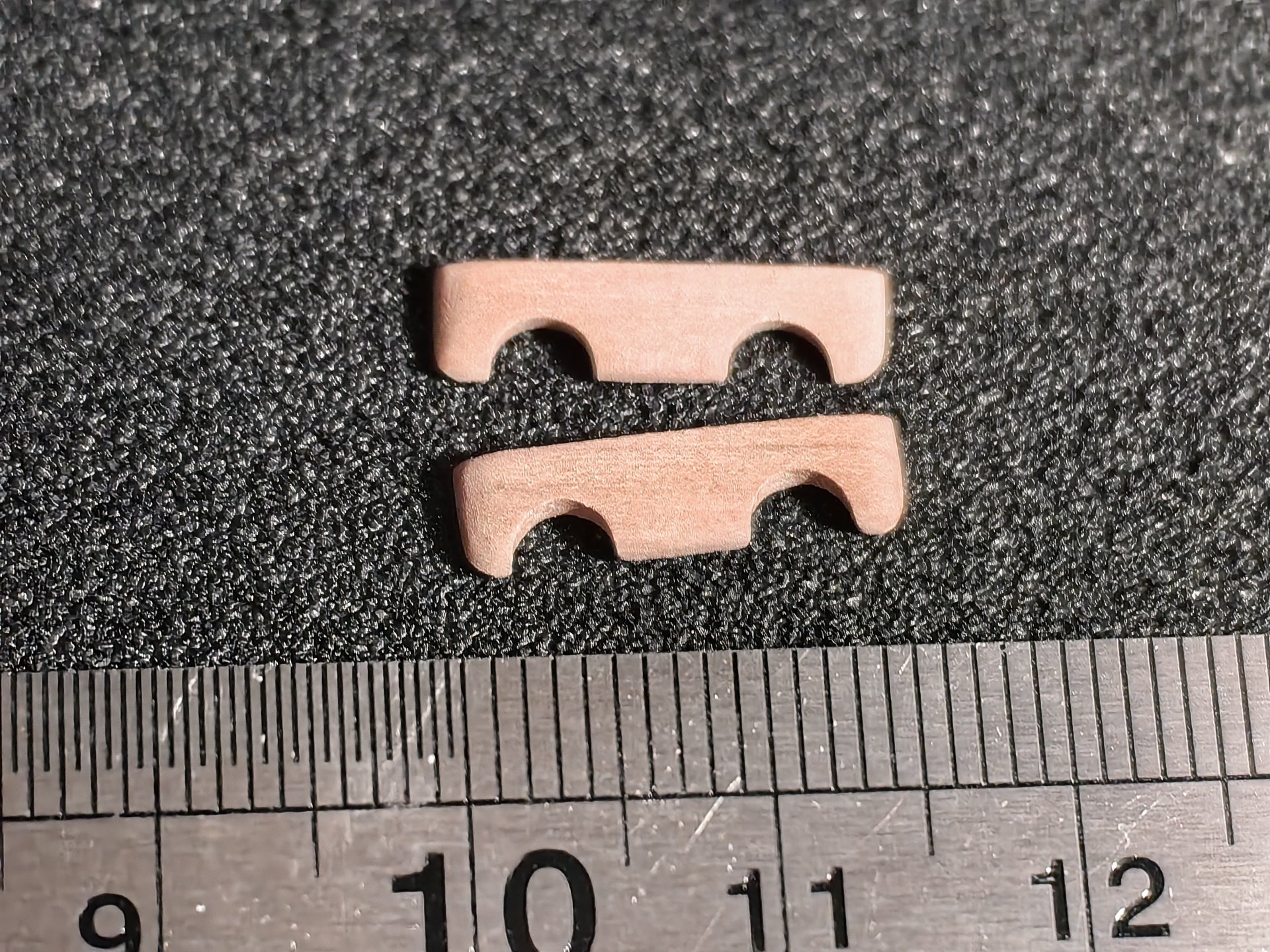
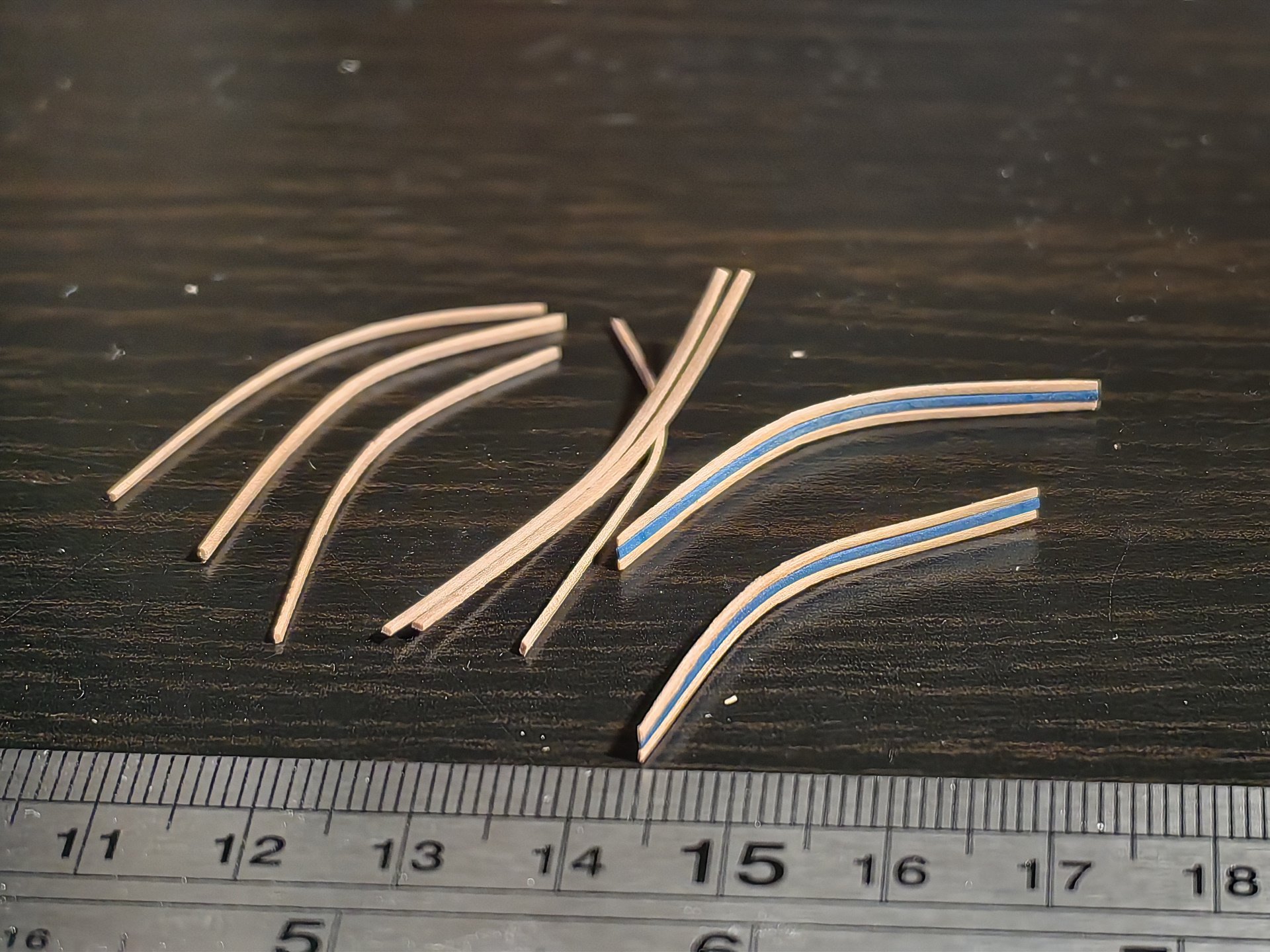
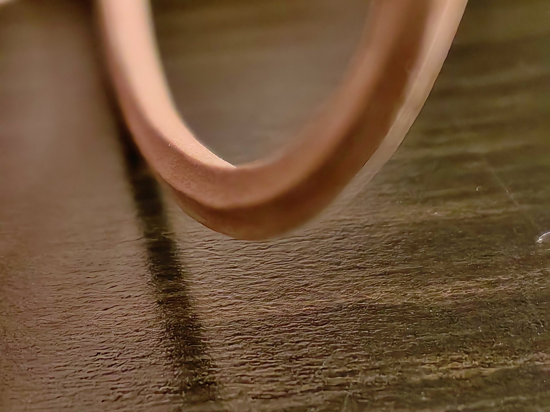
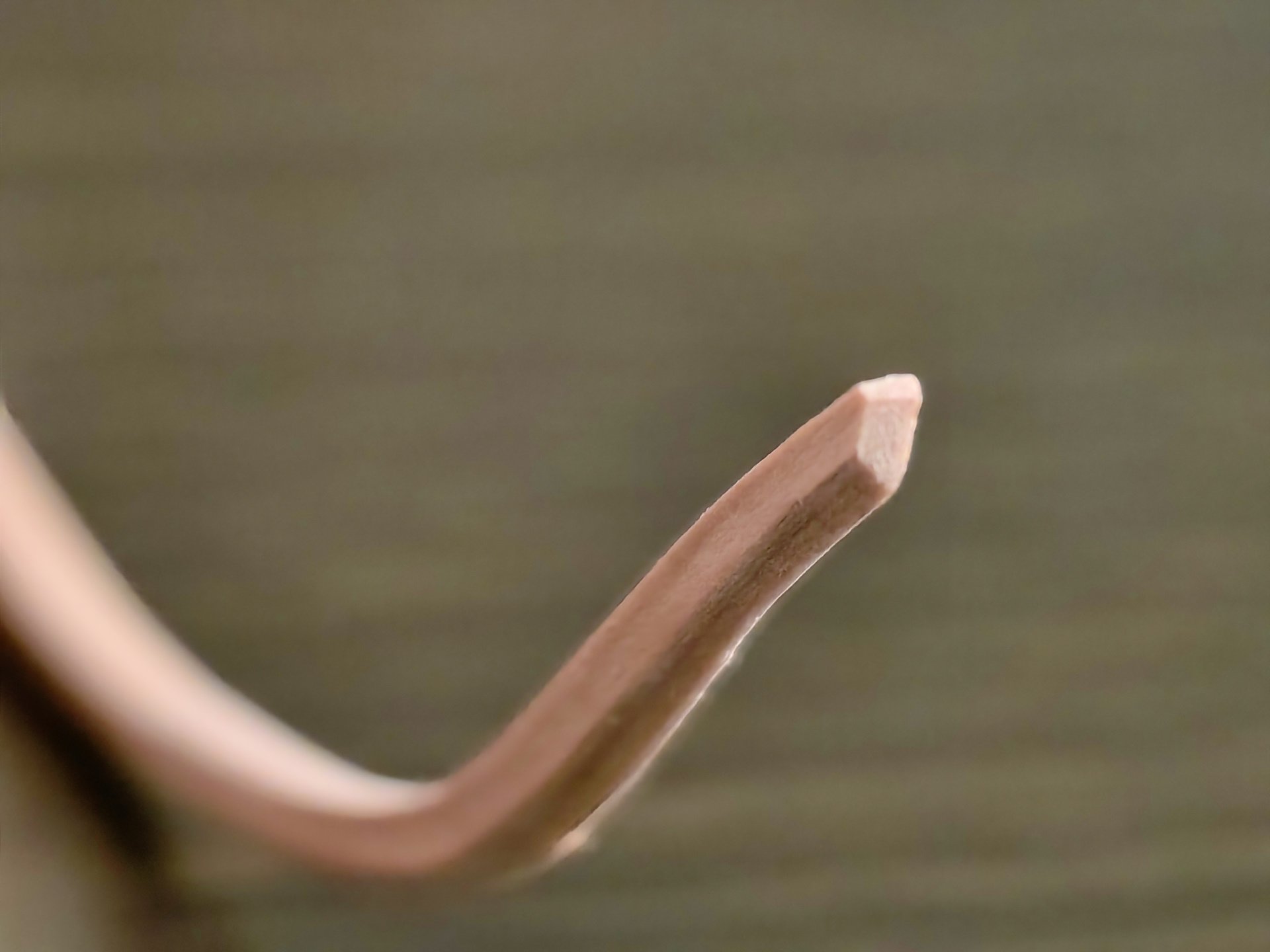
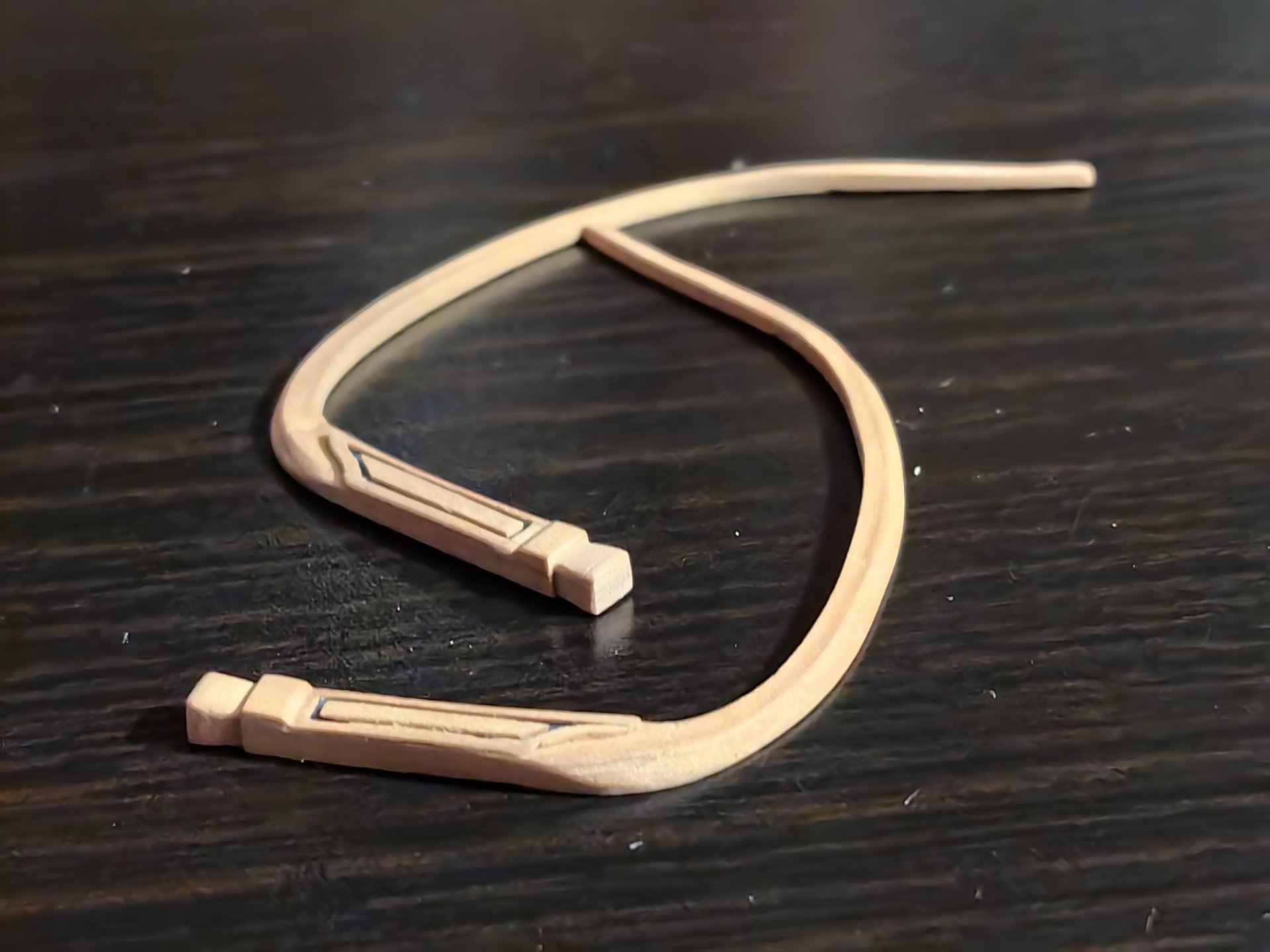
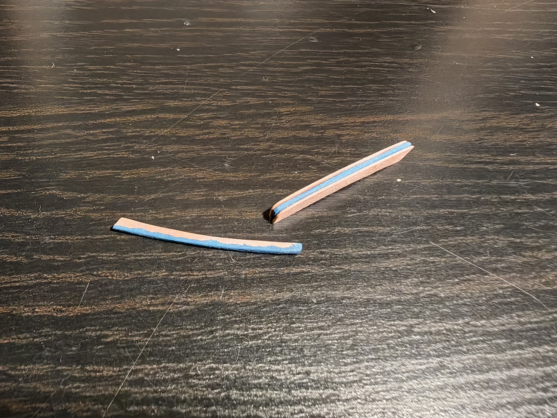
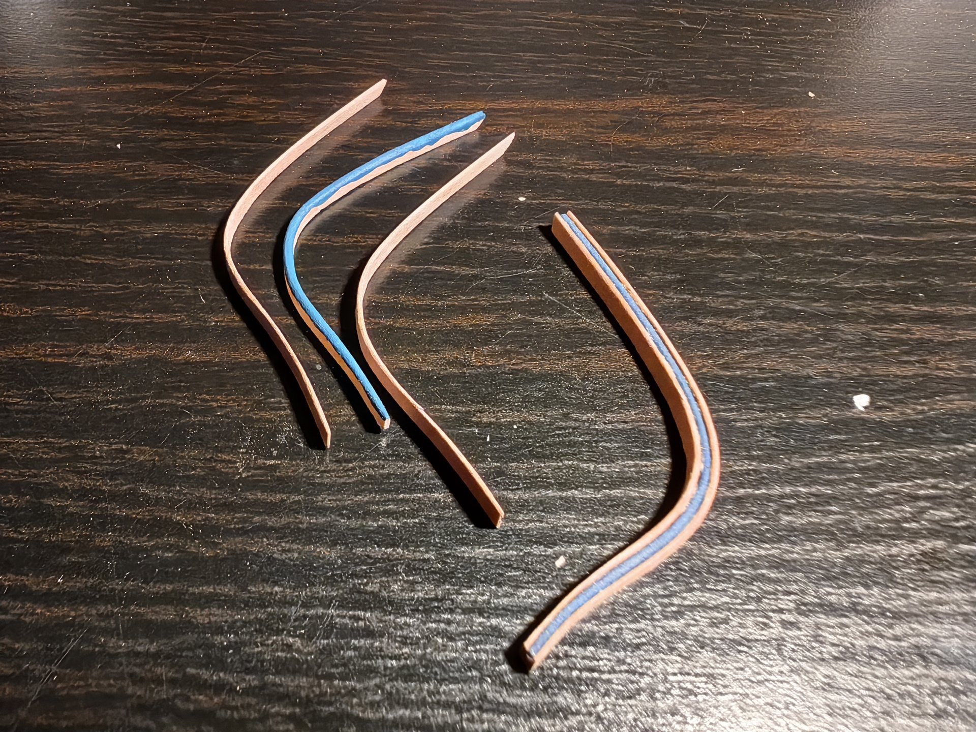
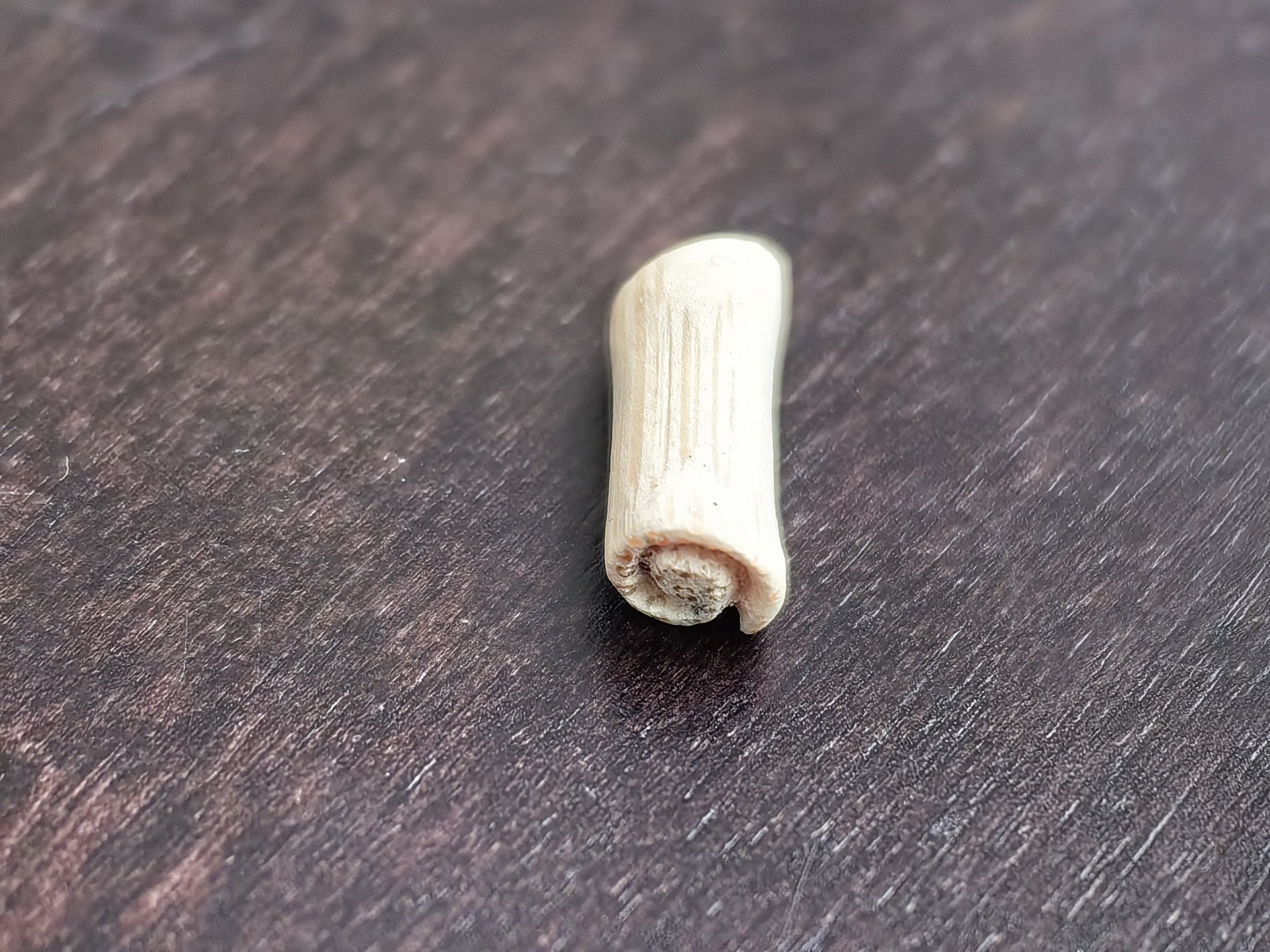
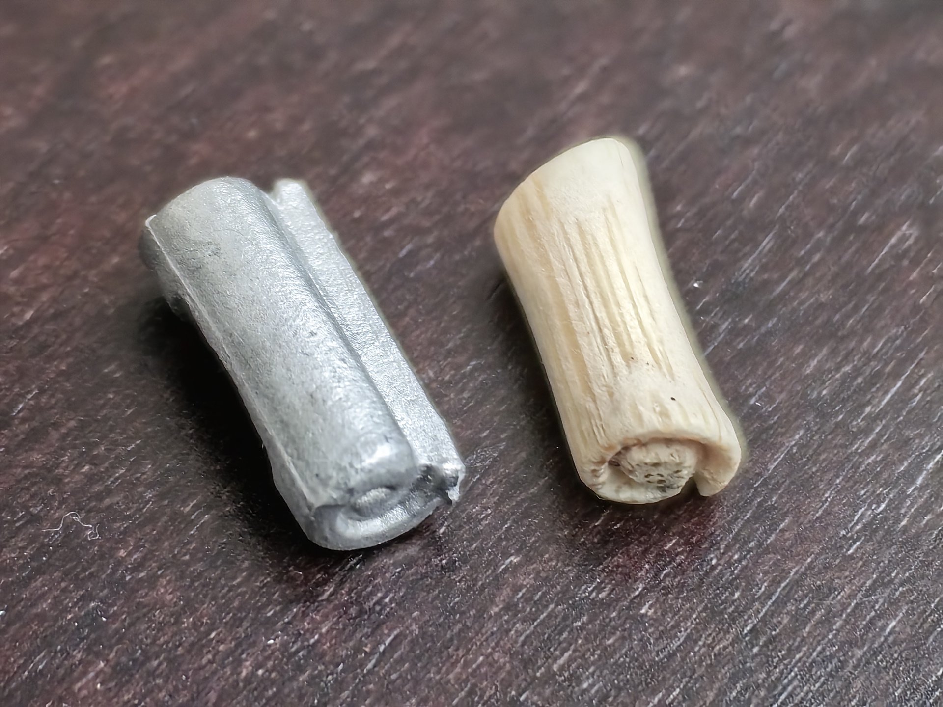
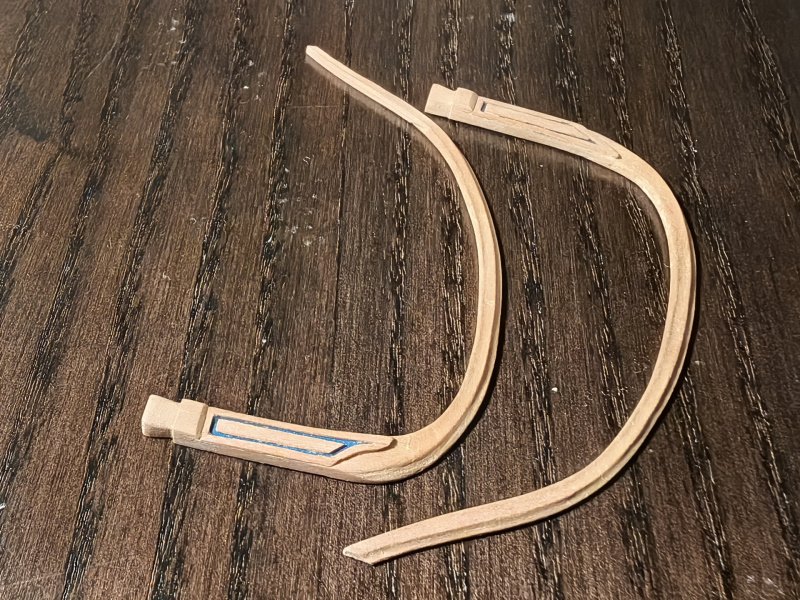
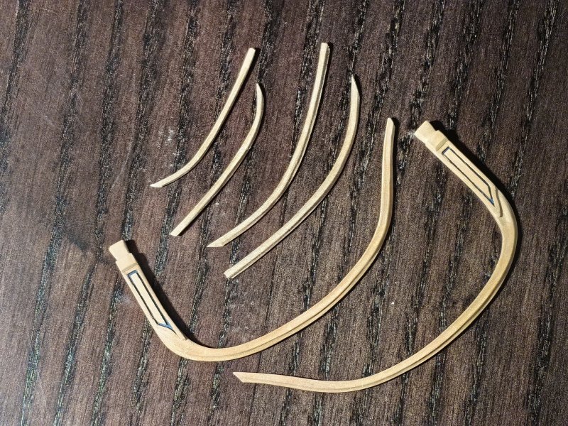
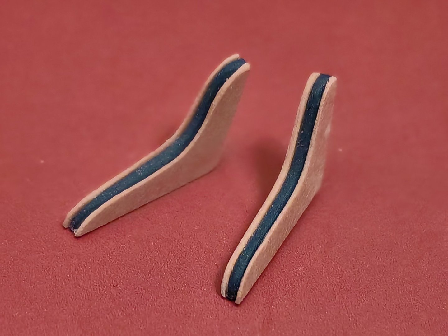
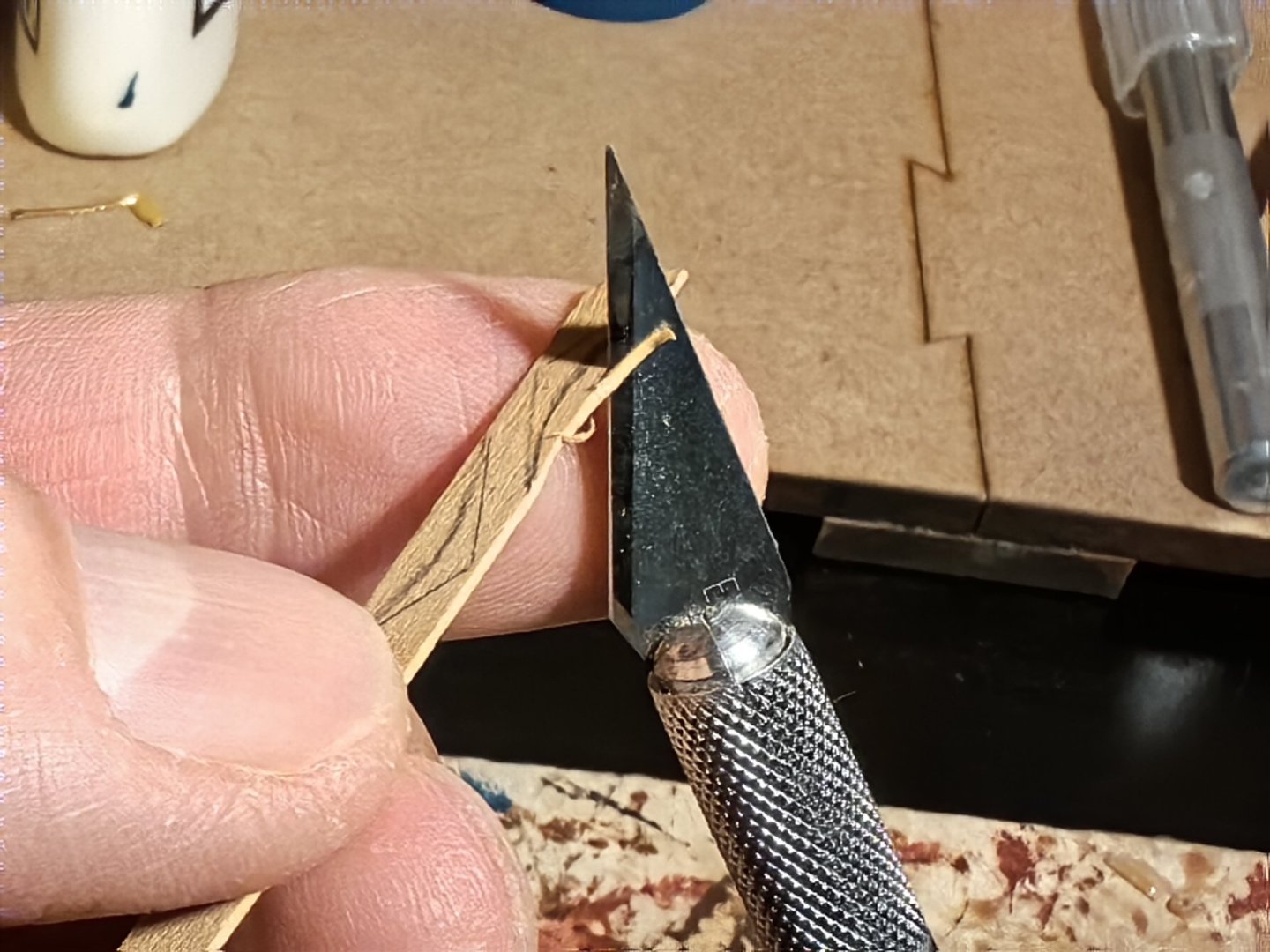
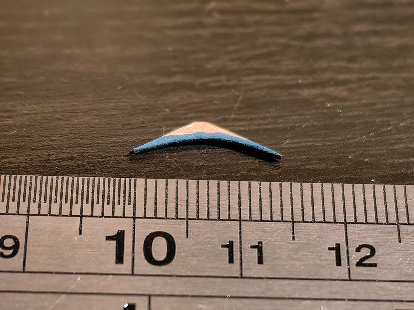
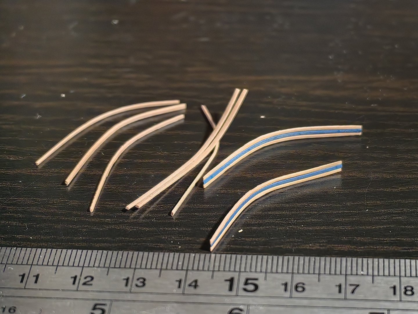
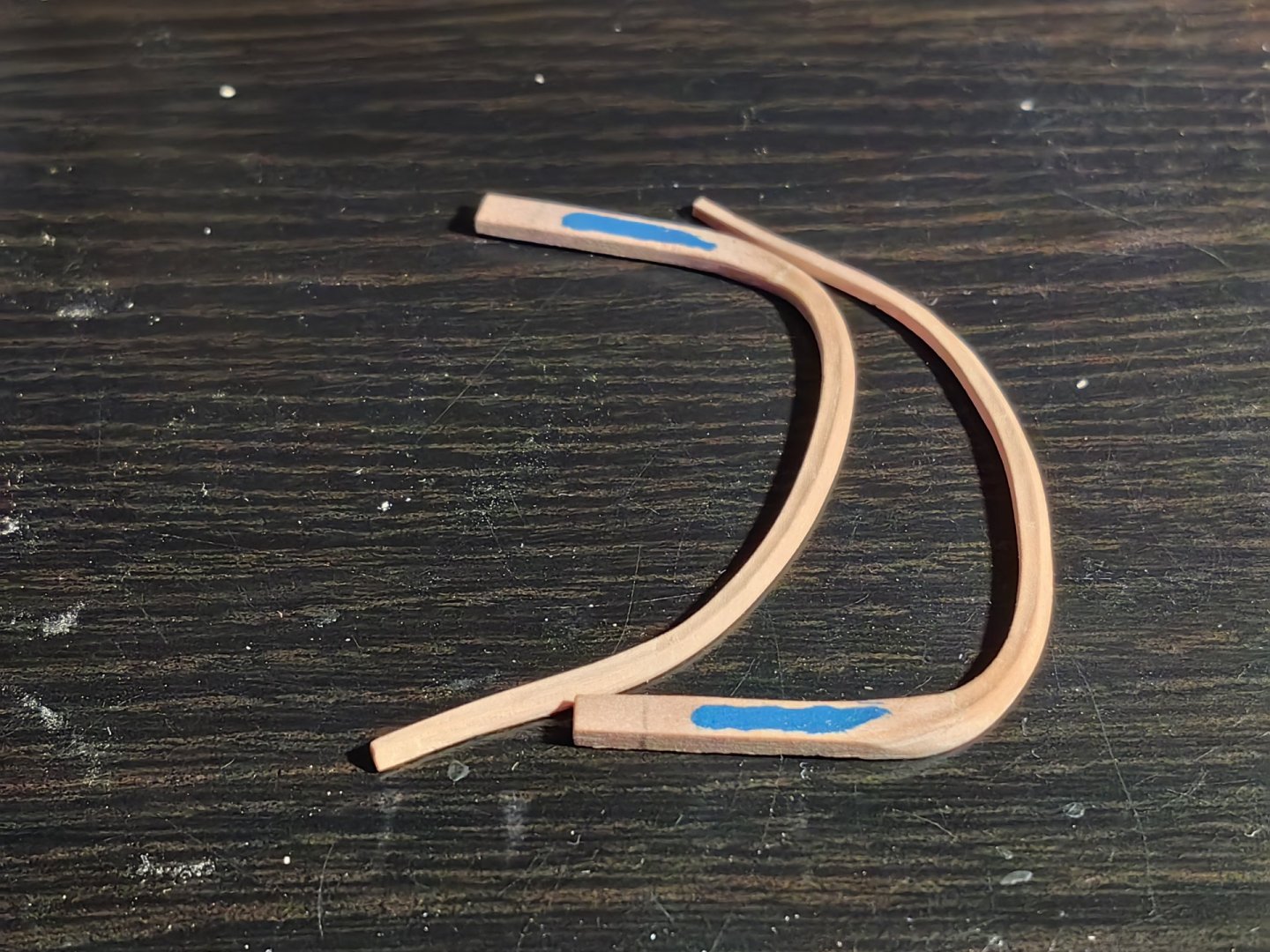
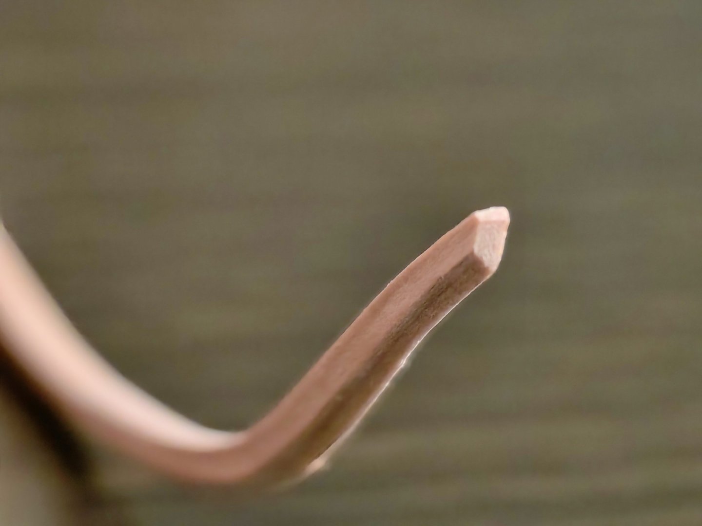
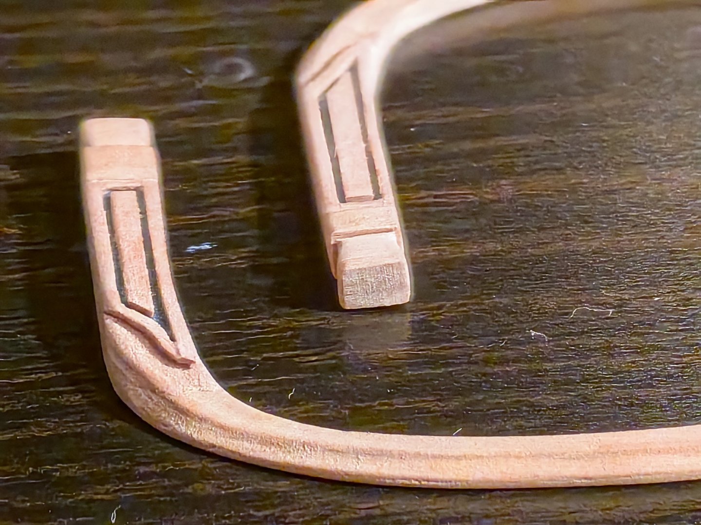
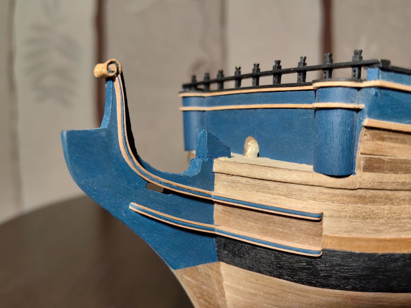
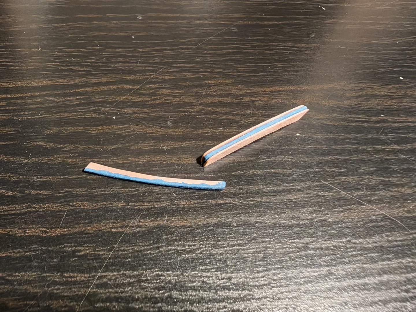
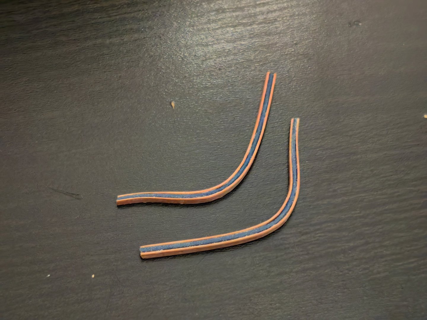
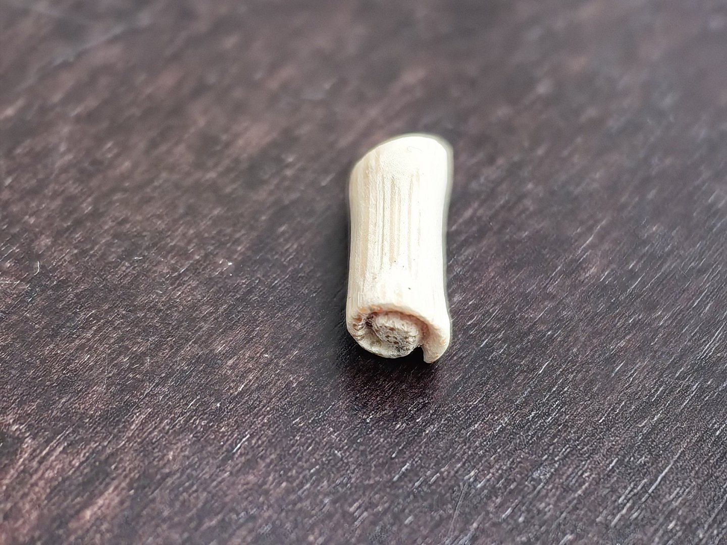
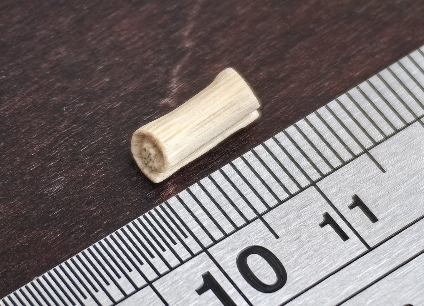
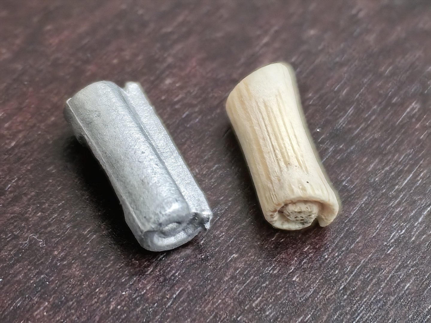
Hi! I'm continuing with the head. I need to make a lot of thin, openwork parts. I started with the chееks. The Corel set doesn't have any laser-cut, ready-made parts, but the chееks need to have a distinct profile and the inside of the profile needs to be painted. While I can still give the rake a profile using a special tool, I won't be able to paint such a small part accurately. Therefore, I'm making the chееks out of three parts. The central part is made of a 1 mm rail, and the side parts are made of a 0.5 mm rail. All the rails are made of pearwood. By the way, it is easier to bend thinner rails. Then I gave the front edges of all the rails a semi-circular profile, painted the front part of the central rail, and glued on the side rails. The long upper cheek should taper towards the end, so I sharpened all three rails. However, when I saw the result, I felt that the taper was not sufficient, so I tore off the glued parts, sharpened the rails again, and then reglued them. The upper cheeks converge at the top and rest against the volute of the herbroket. Corel's volute is made in the form of a cast tin part, which I absolutely do not like, as well as most of the metal decor parts. I decided to make it myself. I did not have a pear rail of the appropriate cross-section, so I used a sushi stick. It is made of bamboo, which is quite hard and perfectly processed with a linography cutter. However, it is lighter than pear and speckled. But a little mordant has more or less evened out the colors, and since the piece is very small, I hope that the specks on the model won't be too noticeable.


-
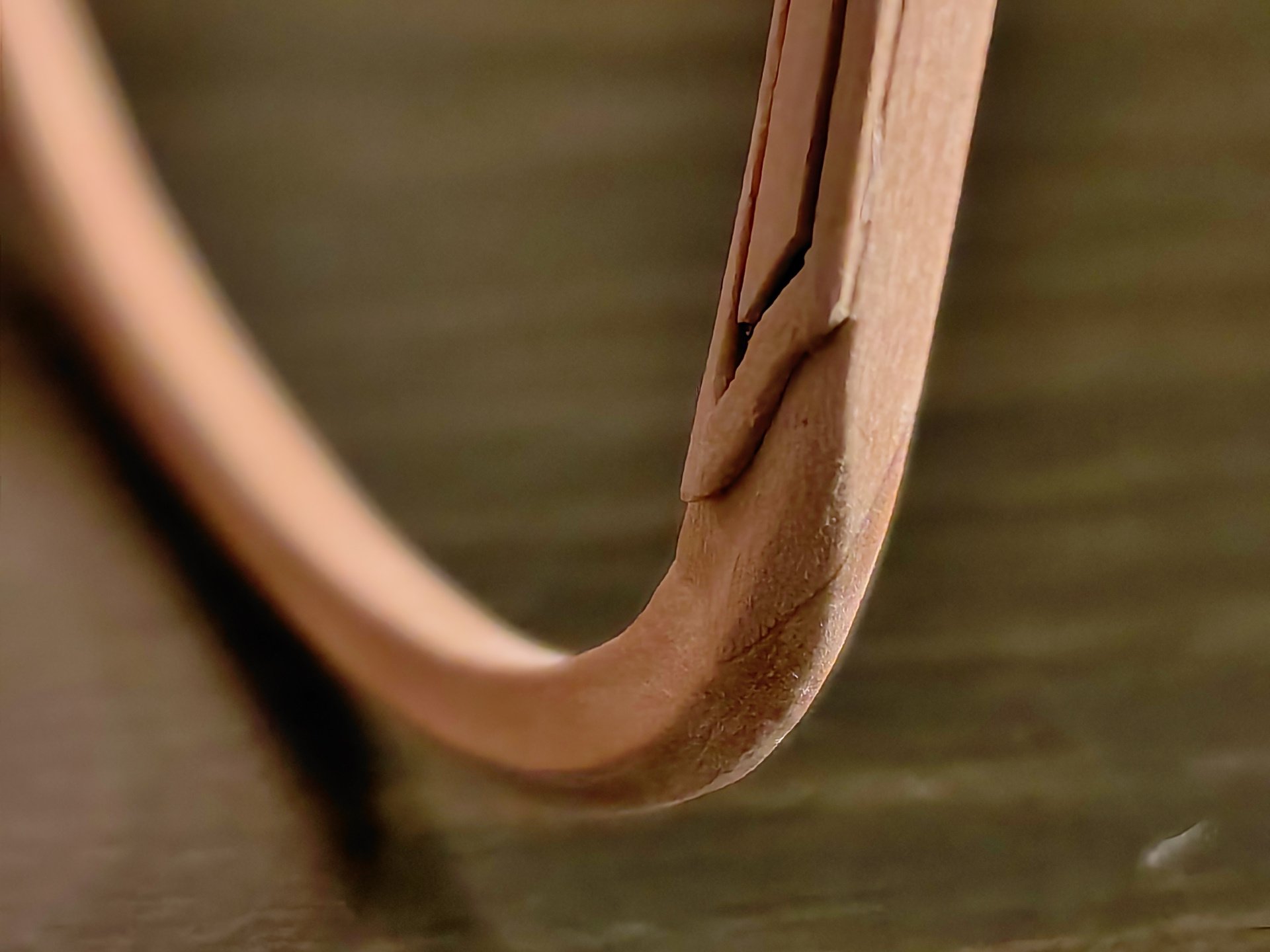
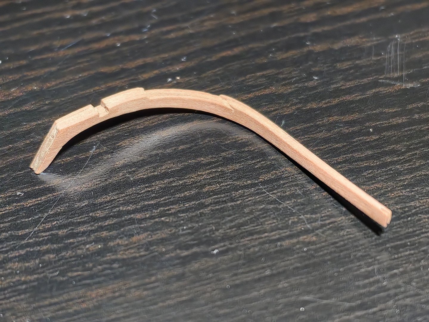
Hi, Nearshore! Thank you for the rating, it's very nice!) I bent the rail by steaming it in hot water and then ironing the tip with an iron, gradually bending the rail. If the radius is slightly larger, it bends normally. However, in this case, the radius is only a few millimeters, and it caused problems. I think it's important to take your time and repeat the steaming and ironing process several times, as there's a chance of the rail breaking. The first bend turned out to be good, but on the second, where the rack rises up, it broke. And on both sides. And I glued the broken parts with PVA glue, for strength, I glued several small pieces of thin rack into the concave part and then, when the glue was dry, I processed it with a round file. So, in fact, you are right, this part is composite, in two parts. Probably, you can not suffer and make it composite at once. In the future, I will probably do it. Yours sincerely, Frecap.
-
Thank you!) The monitor screen may not have very accurate color reproduction. This is not brown, it is black.
-
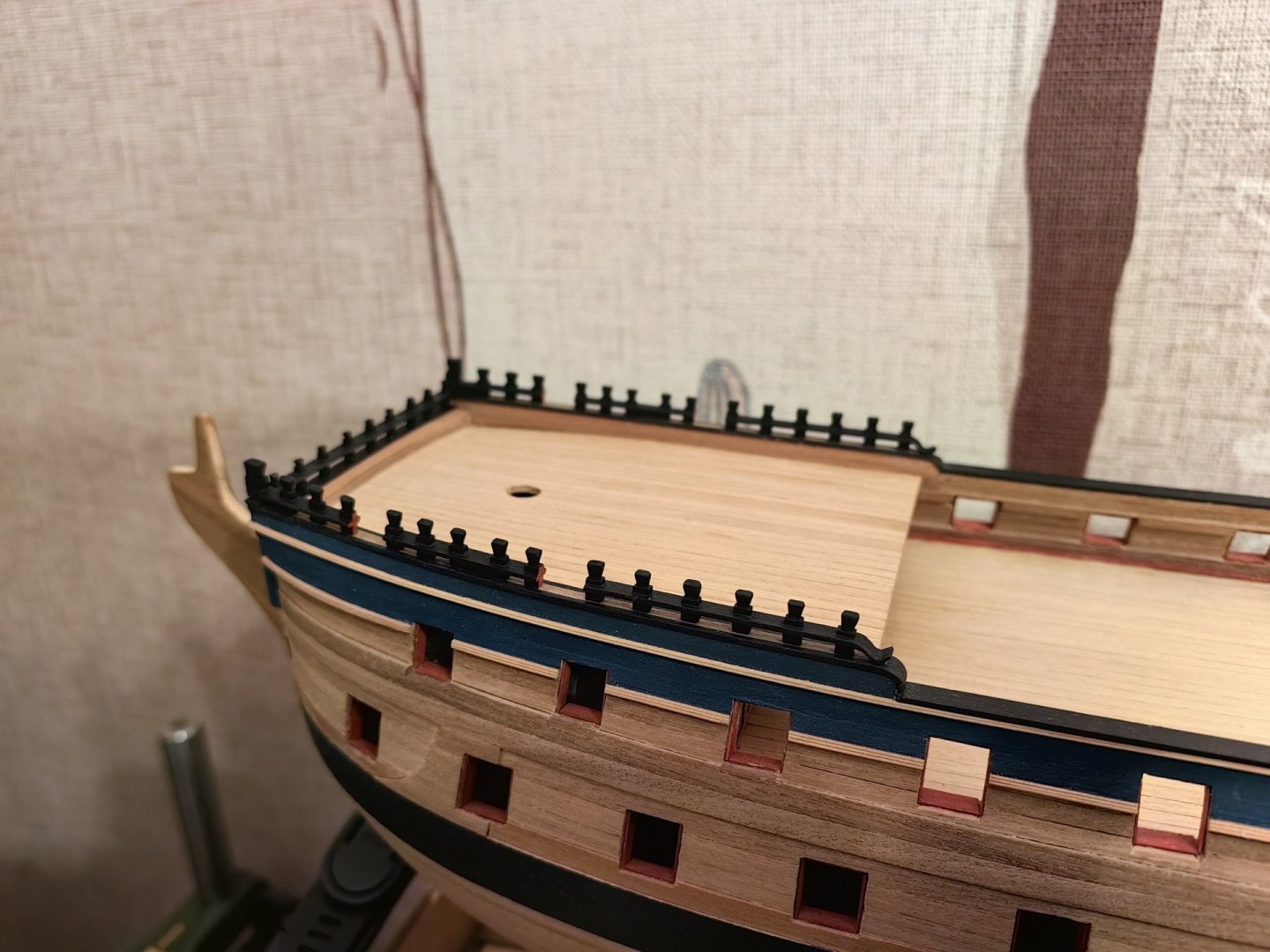
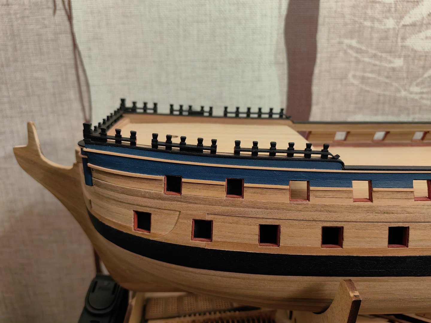
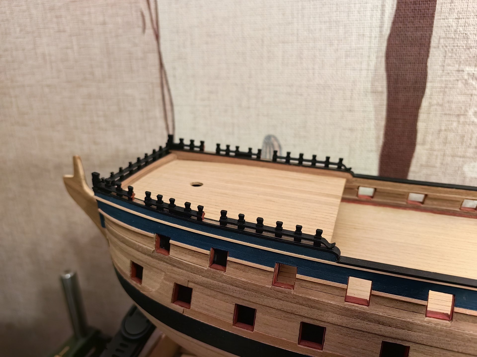
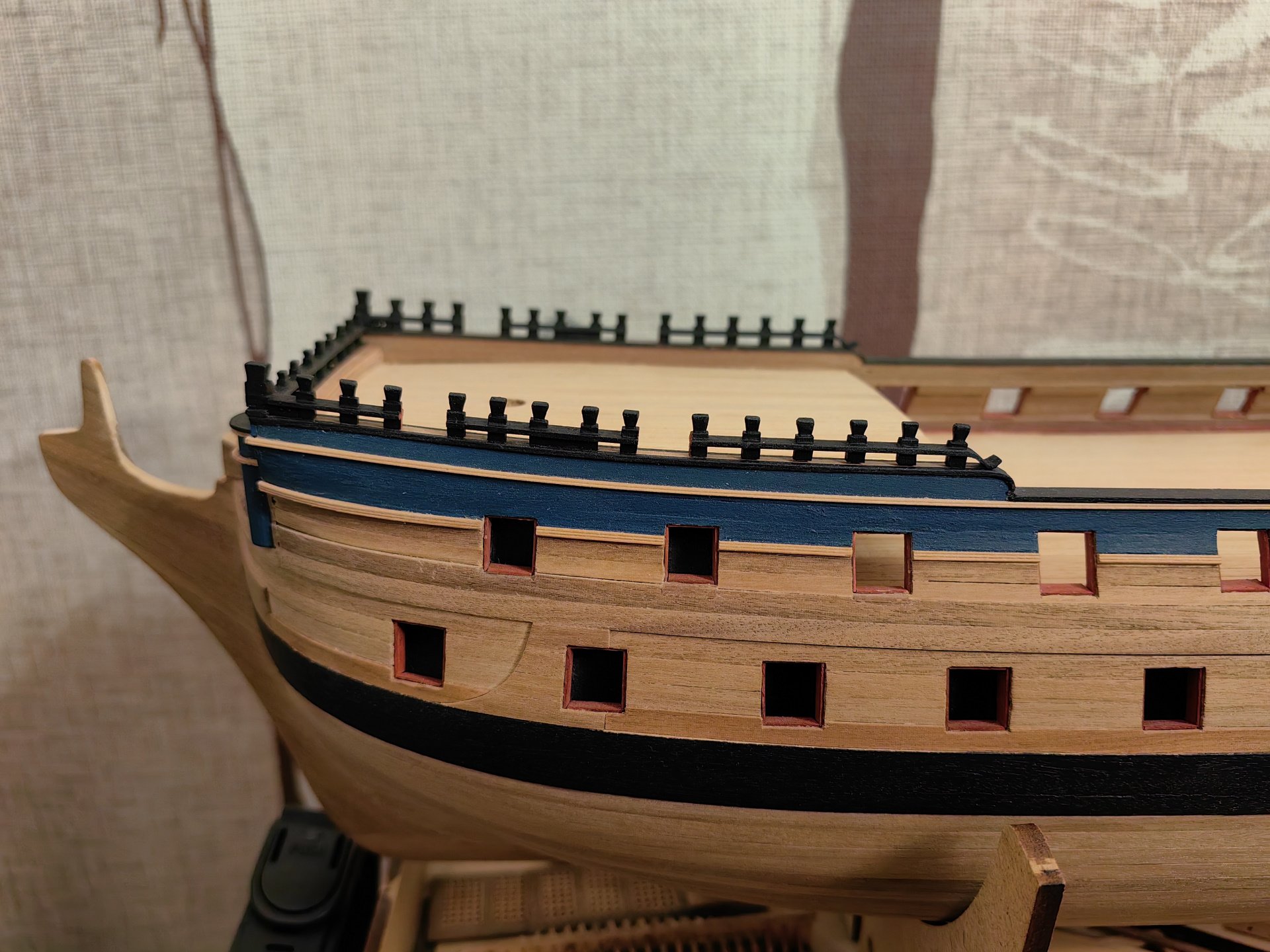
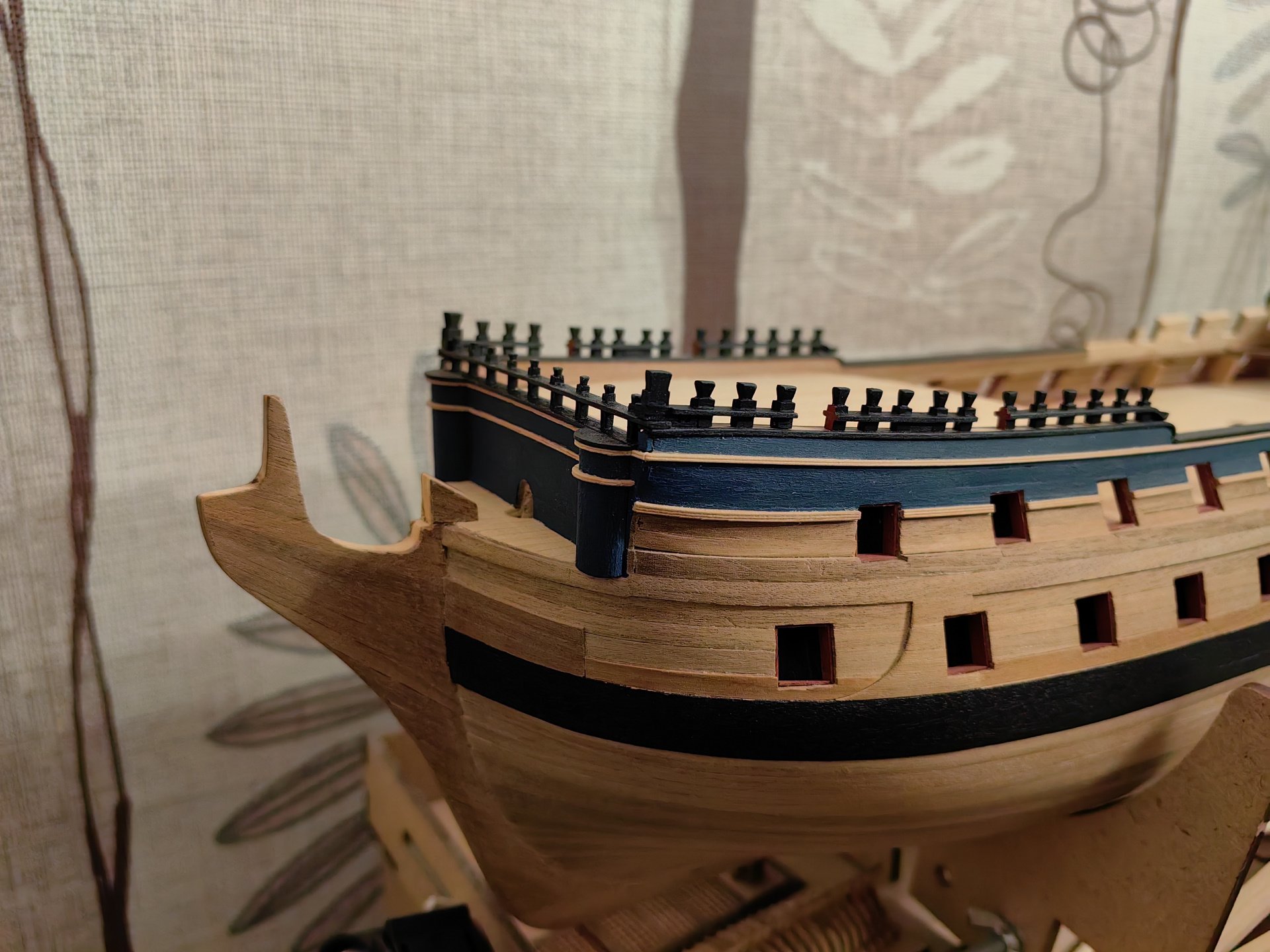
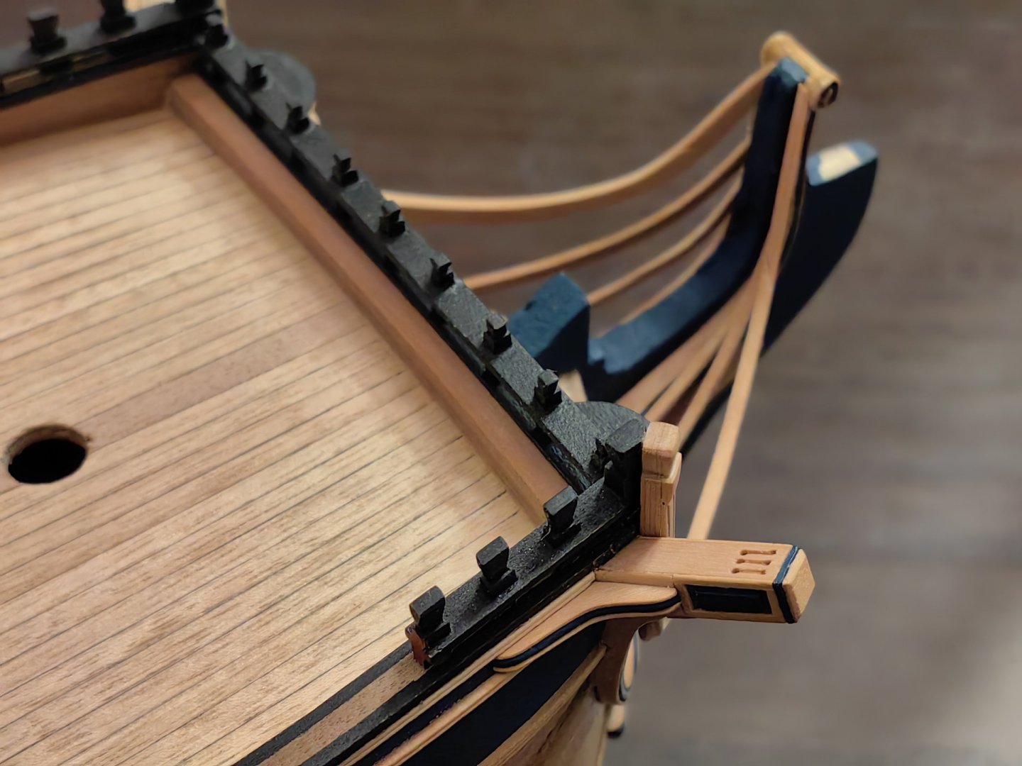
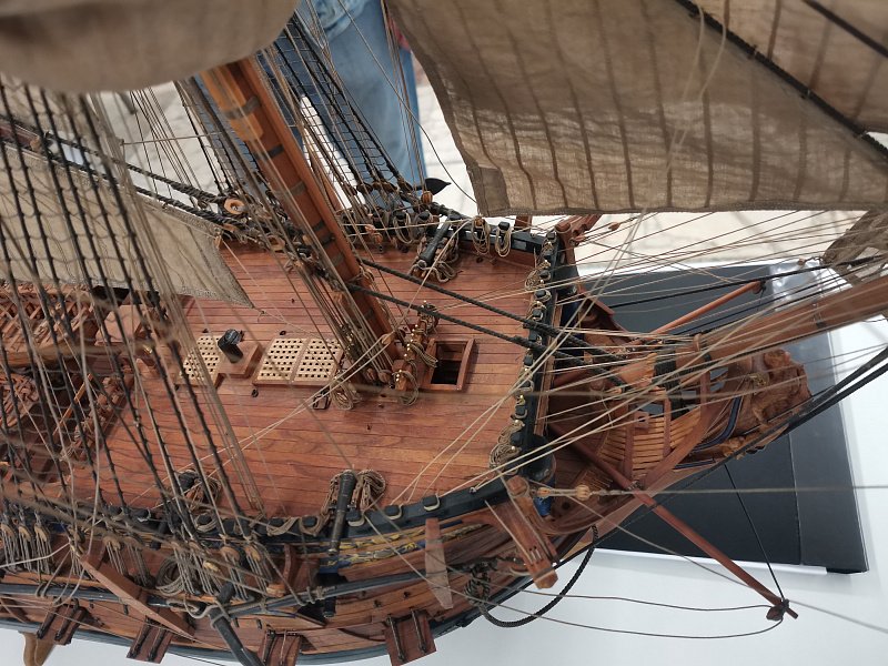
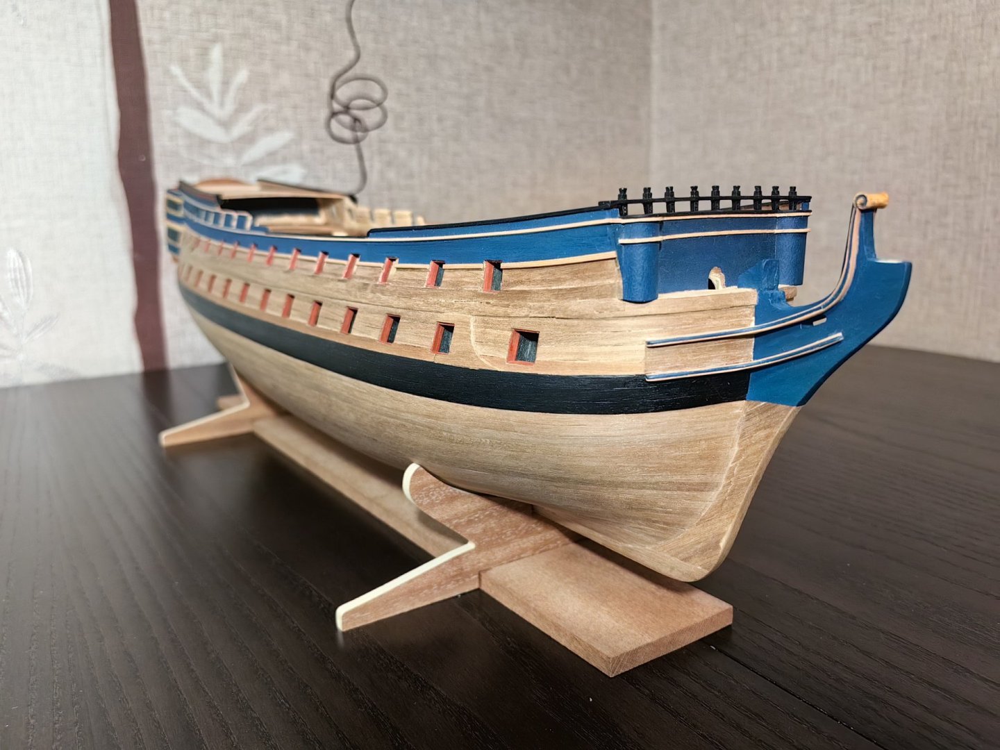
I mounted the gunwale on the bulwarks of the fordeck. I painted it, as well as the rails and toptimbers. I left an unpainted strip on the gunwale for better adhesion when gluing. But I won't glue the toptimbers yet, as there is still a lot of work to do with the case and I don't want to accidentally break the fragile structures. But I couldn't resist and took some photos).