HOLIDAY DONATION DRIVE - SUPPORT MSW - DO YOUR PART TO KEEP THIS GREAT FORUM GOING! (Only 75 donations so far out of 49,000 members - C'mon guys!)
×


kellrandy
-
Posts
77 -
Joined
-
Last visited
Content Type
Profiles
Forums
Gallery
Events
Everything posted by kellrandy
-
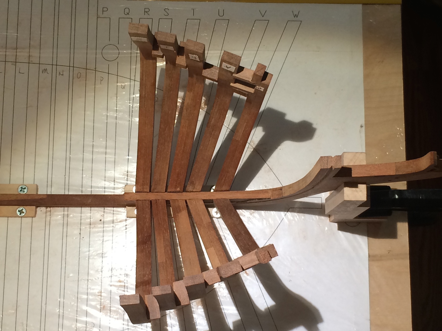
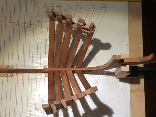
Thanks Richard. I'll be using the ones bundled with the keel, stem, and stern parts. I compared them and both sets came out the same, just that the ones with the keel is more detailed with the beveling lines and so forth. Now for a few progress pics... Got the fore cant frames raised. Now I'm off with the hawse frames, following Daniel's method in his log. Thanks for that by the way, Daniel. Doing a test set first with some scrap pine I had laying around to work out everything and so I don't waste the mahogany. Take care guys and happy modeling!

-
Hey again everyone. I have the fore cant frames done and am in the process of raising them. While I wait for the glue to cure during the raising process, I was going to move onto building the hawse frames. I noticed two sets of them and was wondering which ones I should be using. There is a set bundled with the frames, and another set bundled with the keel, stem, and stern parts. which set did you guys use? Any info would be greatly appreciated. Thanks everyone.
-
Glad I could help a little and hopefully that's the right answer. I'm off to build more frames...
-
Hi jaerschen, Thanks for the compliment, and many more thanks for pointing out that frame. I can't believe I didn't see that before. I guess when you stare at something too long you don't see everything. I double checked my measurements to make sure the others were good, and luckily they are. I've only faired on the floors so far which I'm happy I haven't touched the tops yet. It's off by enough to where it won't fair in correctly though. I had already planned to place temporary bracing all the way around the top of the hull on the inside to make it more sturdy during the fairing process to avoid catching a corner and breaking something. I'll back able to pull it back in line then. Thanks again for noticing that. Randall
-
Richard, I was looking through the plans again and noticed one called "28 Frame Notch". Where the notch is shown in the plan, it looks like the wing transom fits right into it with the small corner sanded off of the transom as shown in the plan for the transom. The back of the transom with the other little corner sanded off looks like it would fair right into the frame as you see in the other drawings. Might be something to look into further. Hopefully it helps some. Good luck with your build, it is looking very nice. Randall
-
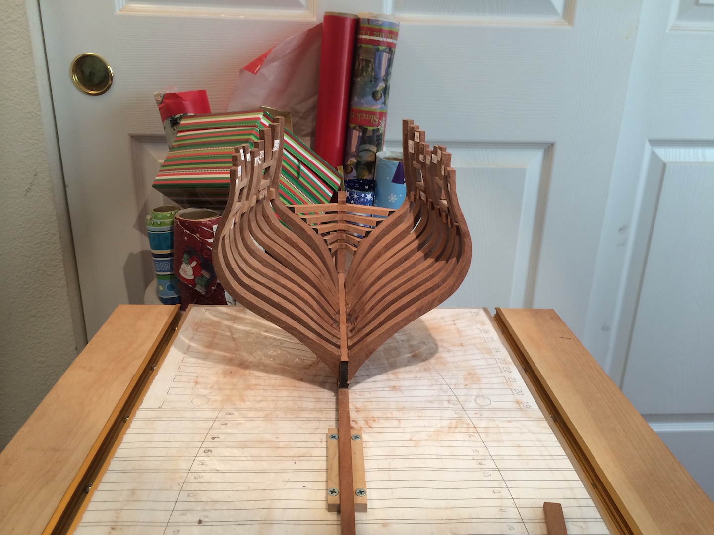
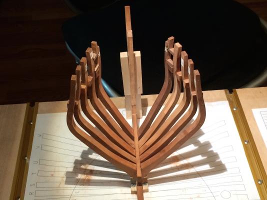
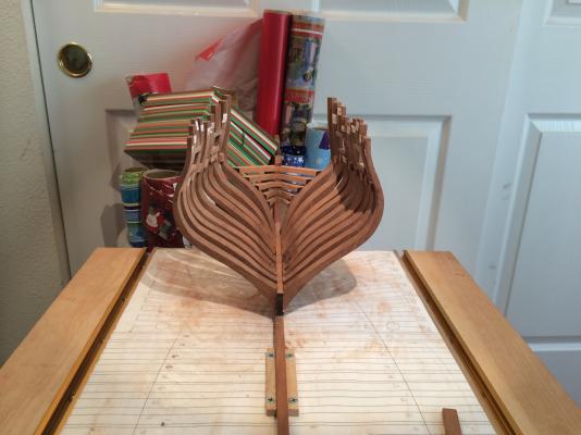
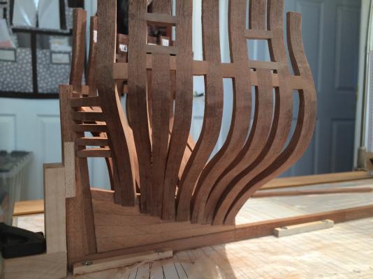
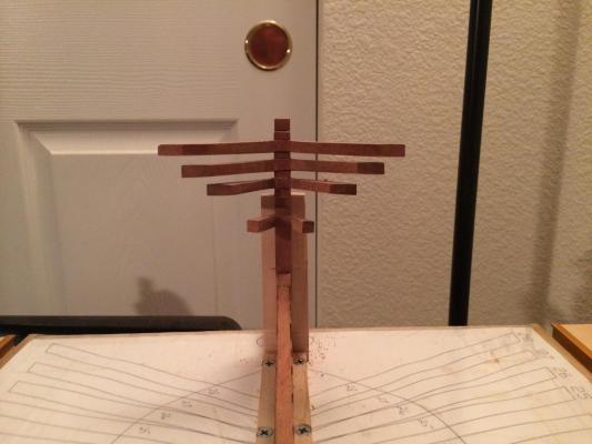
Hi everyone! Got the aft cant frames raised. Please let me know if you notice anything amiss or incorrect. I don't see anything too bad, and am pretty happy with the way it turned out. I haven't done any heavy fairing on them yet, that's the next step, and add the copper bolts to the floor futtocks. I am going to leave 20-23 or so a little thick until I get the aft square frames in so I make sure I don't take off too much. After fairing the aft portion, going to move onto the fore cant frames. Have a good one guys.


-
Hi Richard, I haven't made it to that part yet, just finished up raising the aft cant frames, but I do know there are two different plans for the wing transom, one marked as revised. I'd double check the downloads area and make sure you have the right plan. Randall
-
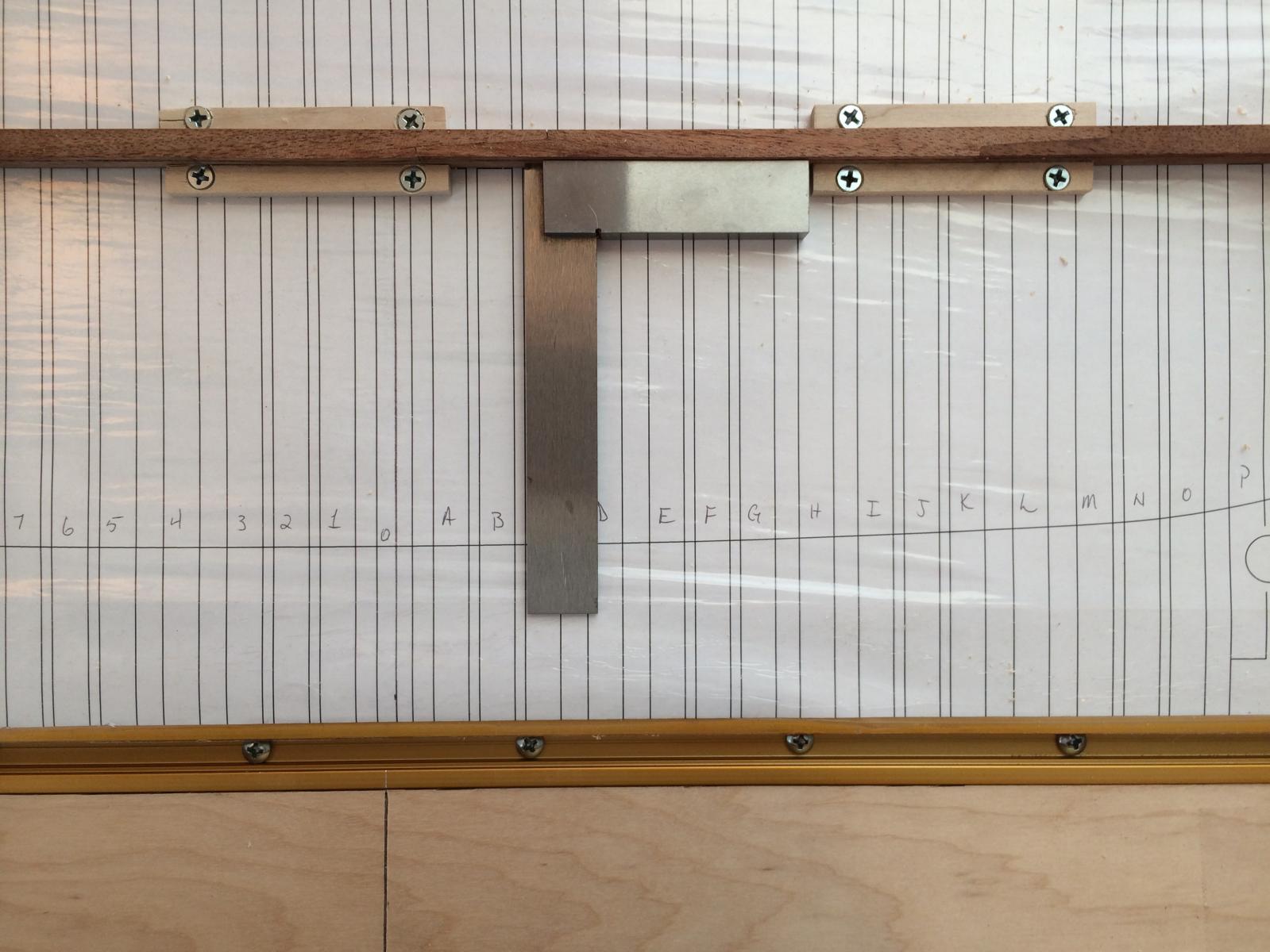
Hi guys! Raising the cant frames is going good and have 27 & 28 up. I just want to verify something before I go onto 26. If you look at the framing template, the guide lines for 25, 26, and 27 cross, so if the frames aren't narrowed on the floor futtocks, then you can't get the fore most frame to land on it's guide line (at least I can't, lol). If I want 26 to land perfectly on its guide line, then I'll have to take a little (about 1.5mm to be exact) off of the fore end of frame 27 on its floor futtocks, perpendicular to the deadwood both horizontal and vertical. Before I do that, I just want to make sure that is what was intended on the plans. If I did do it, the angle for 26 will land it just right along its guide lines.
-
Thank you. My framing jig helped out quite a bit getting them set.
-
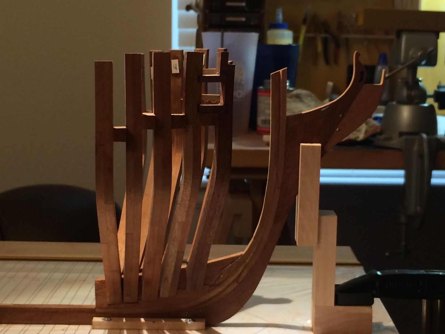
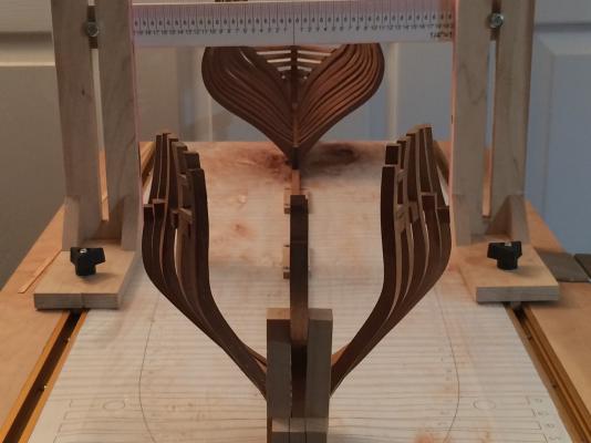
I think I'm back on track, now onto raising the aft cant frames. Here's photos of the stern section redo. I am very happy with it and think it looks better than the original attempt. Happy modeling everyone...


-
Howdy, everyone. Just wanted to chime in and let everyone know how the stern re-do was coming along. It has gone very well. I have the keel, stern post, inner post, deadwood, and transoms redone and they came out much better this go 'round. I'll have some pics of the rebuild tomorrow. Thanks everyone for all of the support and help I have received. I didn't think I would be able to recover, but a little patience and me being so methodical with every minute detail is paying off I think. I feel much better with its progress now and test fitting the frames has gone great. Everything is lining up the way it should now. Thanks again everyone.
-
Thank you, Tim. I needed that little reminder. I wasn't that big a fan of the patched stern post, so I started redoing that last night. I do want to be proud of it and not have any regrets when I look at it. I want to remember how a big mess it was and how I was able to make it right. Thanks again.
-
Stern rebuild progress... Taking apart the keel wasn't as big a deal as I thought it would be and went fine. Nothing came apart that shouldn't have. Have the two end sections ready to go as well as the stern post which I was able to reuse with a small patch on the bottom that's barely noticeable. Still contemplating redoing it because of the patch, but I think it looks good. Next up is the deadwood and two aft sections of false keel... again, lol.

-
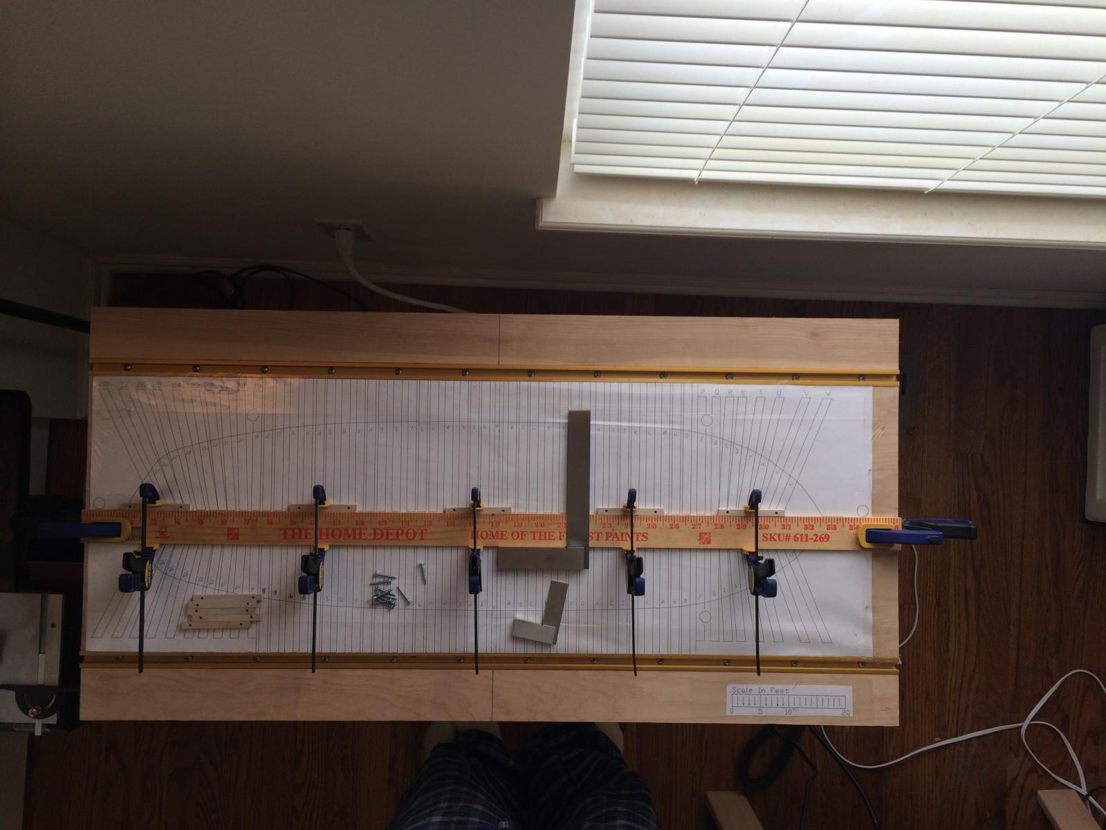
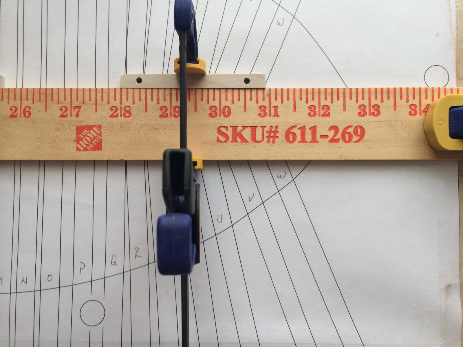
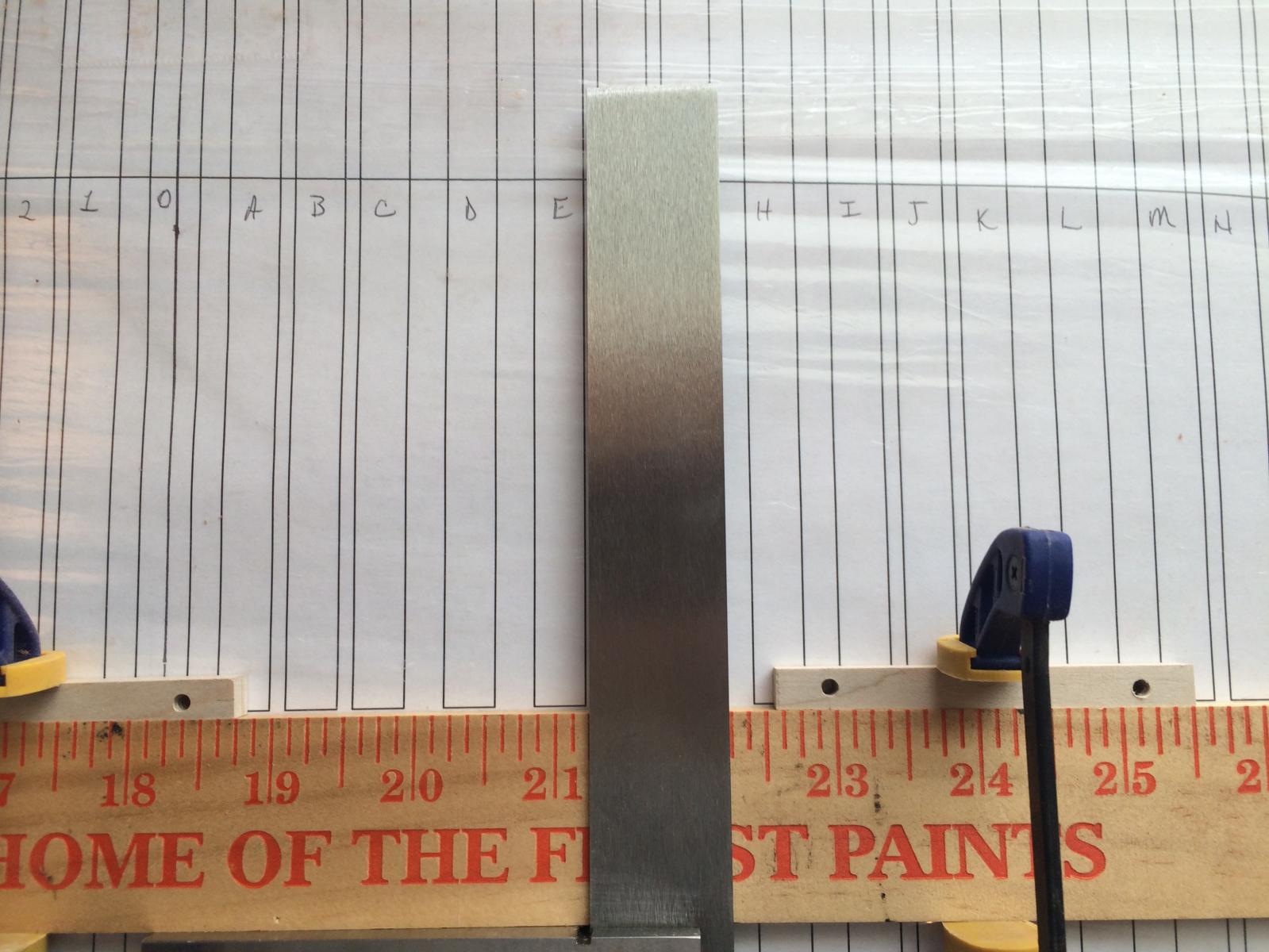
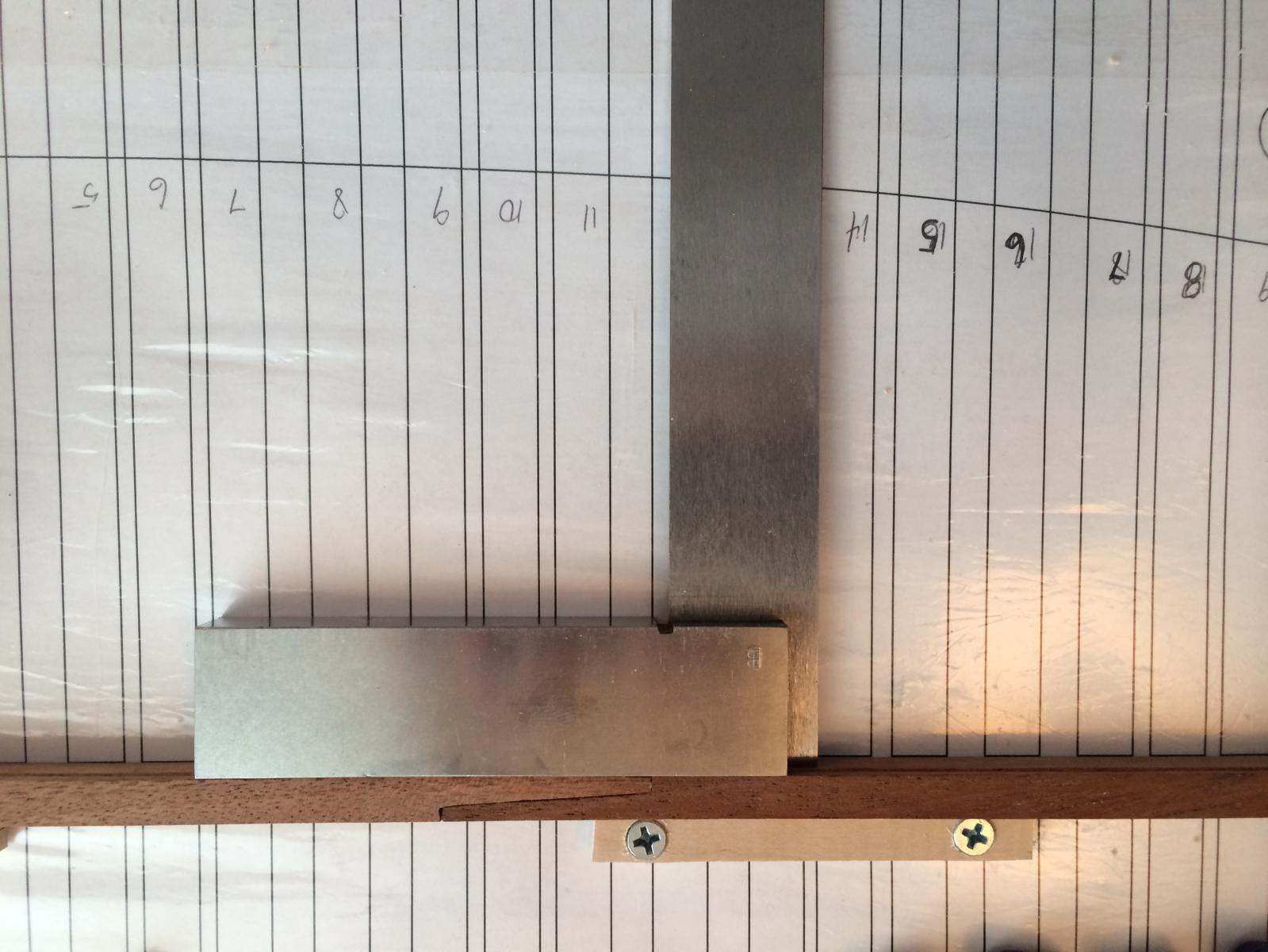
Yeah, I check all of them. The ones I print come out fine with the scale on them. They come out to a perfect 1/4" between tick marks. I also double checked the framing template I had printed at a local office shop, came out fine. Weird thing is that so did the keel plan according to the scale on it, but it's off. The cutting templates for a lot if the parts don't fit. They're off around 5/16 of an inch in what I have printed. Things are working out fine when I don't mess with that plan, so it's just a reference now for what goes where.
-
No, I haven't done any beveling on the frames yet. I just cut them to the widest part of the templates like I have seen done in other logs. I plan on doing the beveling after they're up. All I have done so far with them is setting the angles on the floor futtocks.
-
Thank you for that explanation, I do see it now and does make sense, but the stern portion is pretty bad. Earlier in my build, I was having a lot of issues with the keel plan versus what came out from the cutting templates for the keel, deadwood, transoms, etc. They were all about too big versus the keel plan, so I cut the parts to fit the keel plan. Now, on the framing jig, the frames are not fitting the deadwood at all because now it's all too short. I could get 28 & 27 to fit on their step, but the rest were pushed too far out and off of their steps. I also made the template for the steps from the keel plan. Comparing them to the cutting template, they're pushed too far back. I thought my plans were printing out too big, but now I can surely see they are coming out fine. So I'm glad I can get over things quickly. Here's my plan, re-do the stern portion. I'll remake the last two sections of keel so it's right and the deadwoods stop at frames #19 for the stern and Q at the fore sections as this is what the DOF shows. Then redo the stern post, inner post, deadwood, and transoms, trimming only to the cutting templates as I did on the stem. I believe this will put me back on the right track, I hope.
-
Well, I think I figured it out. It started with the keel and trimming to fit the keel plan. That means I pretty much have to start over yet again. I'm really on the verge of giving up completely. We'll see how I feel about it in a few days. Right now, I'm done and completely defeated.
-
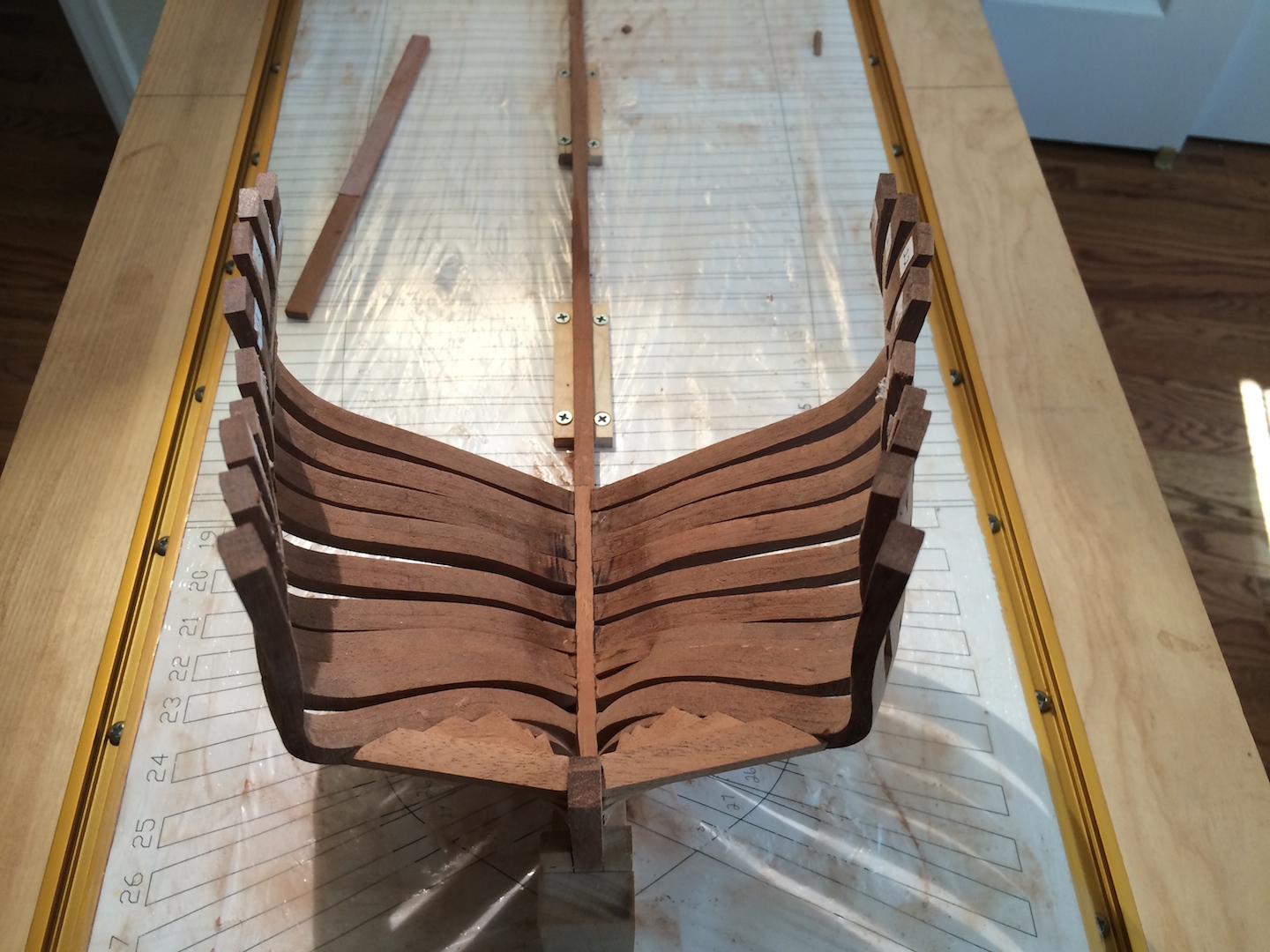
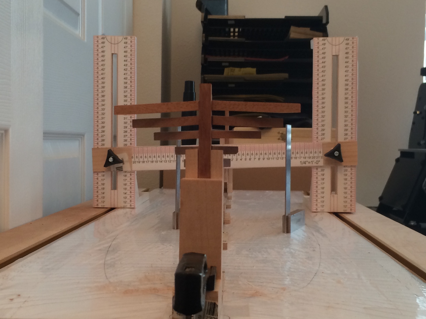
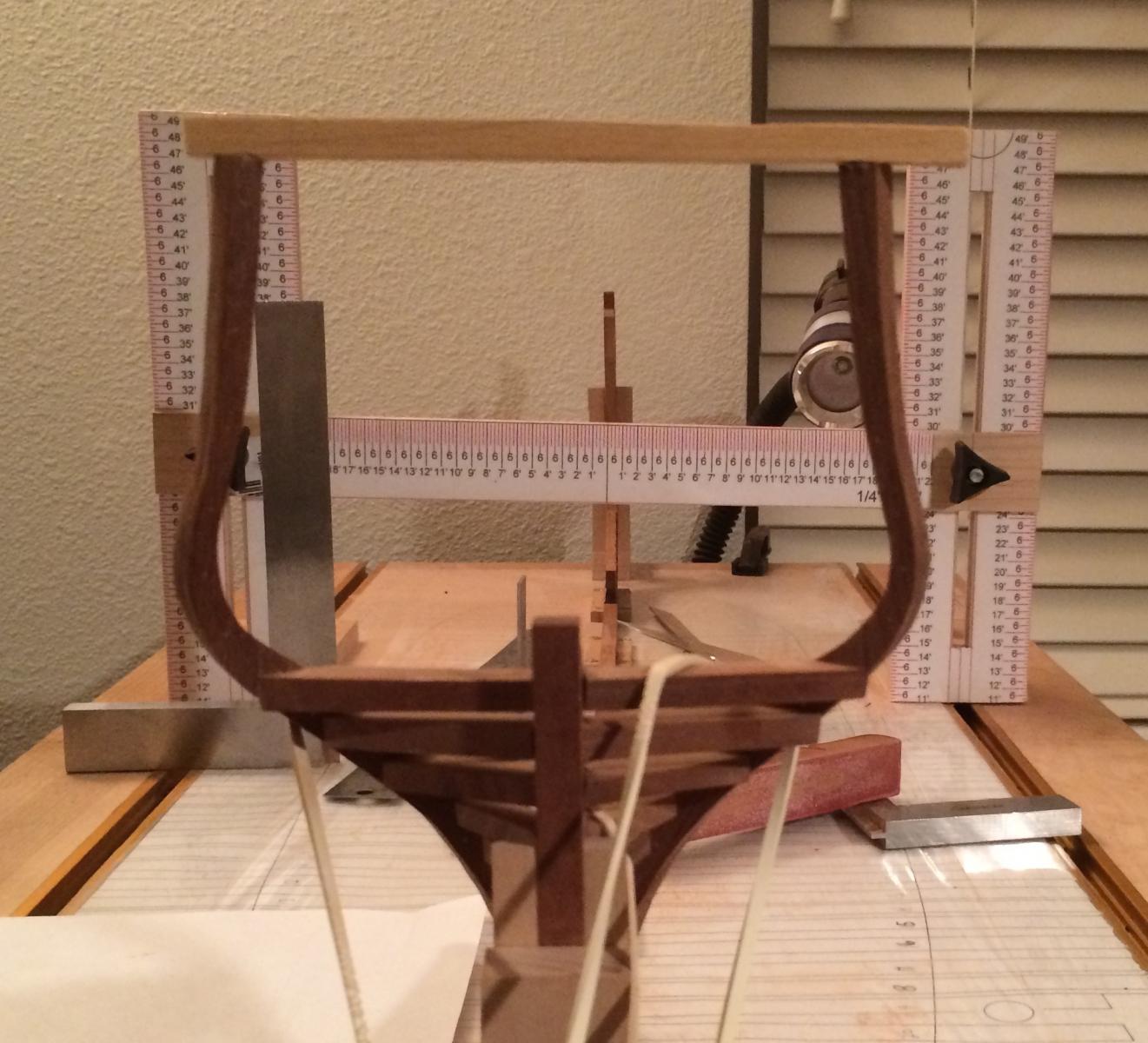
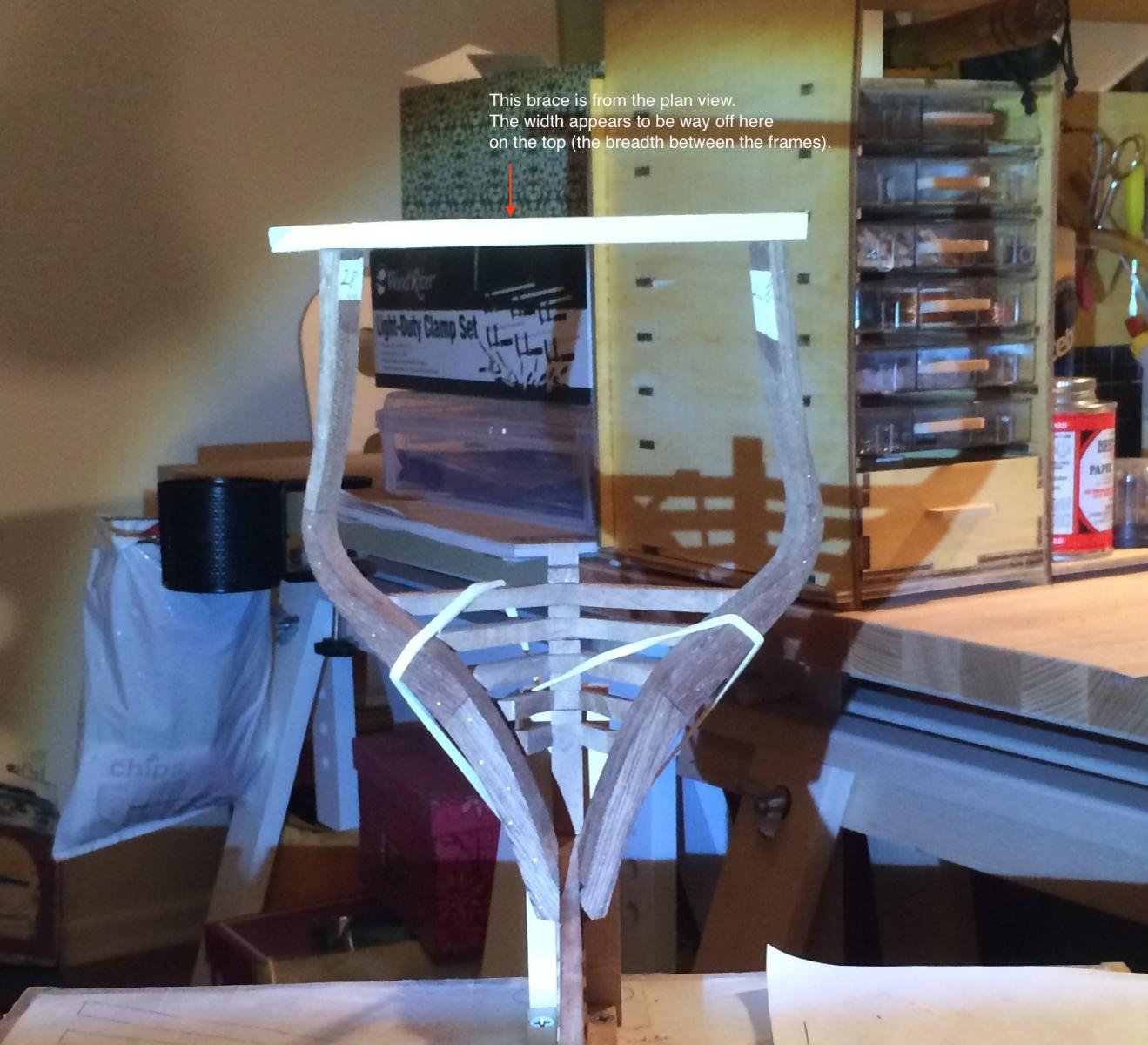
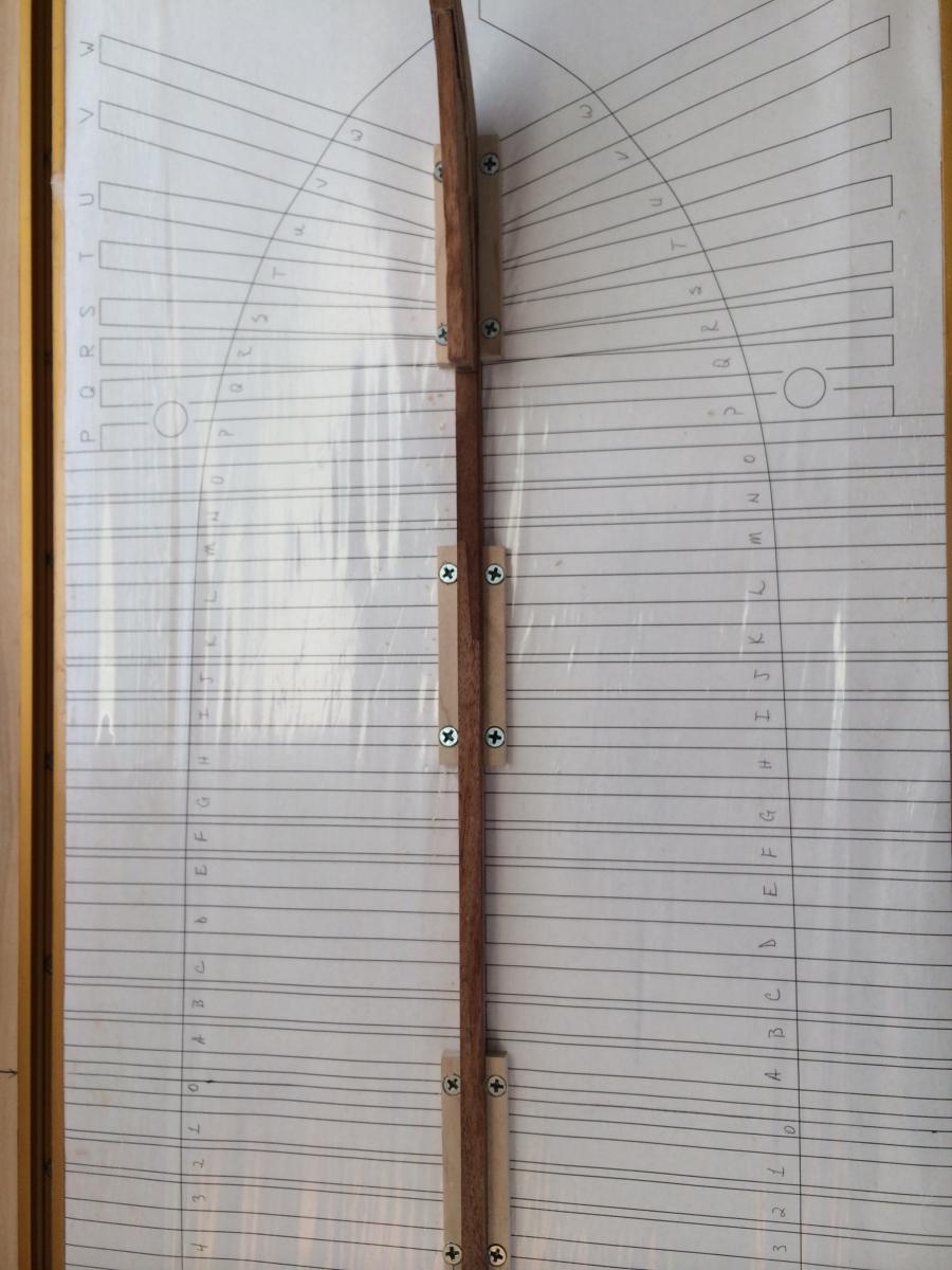
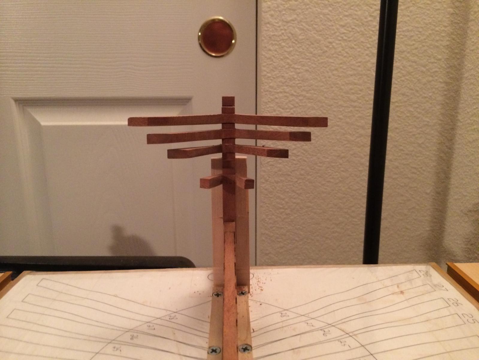
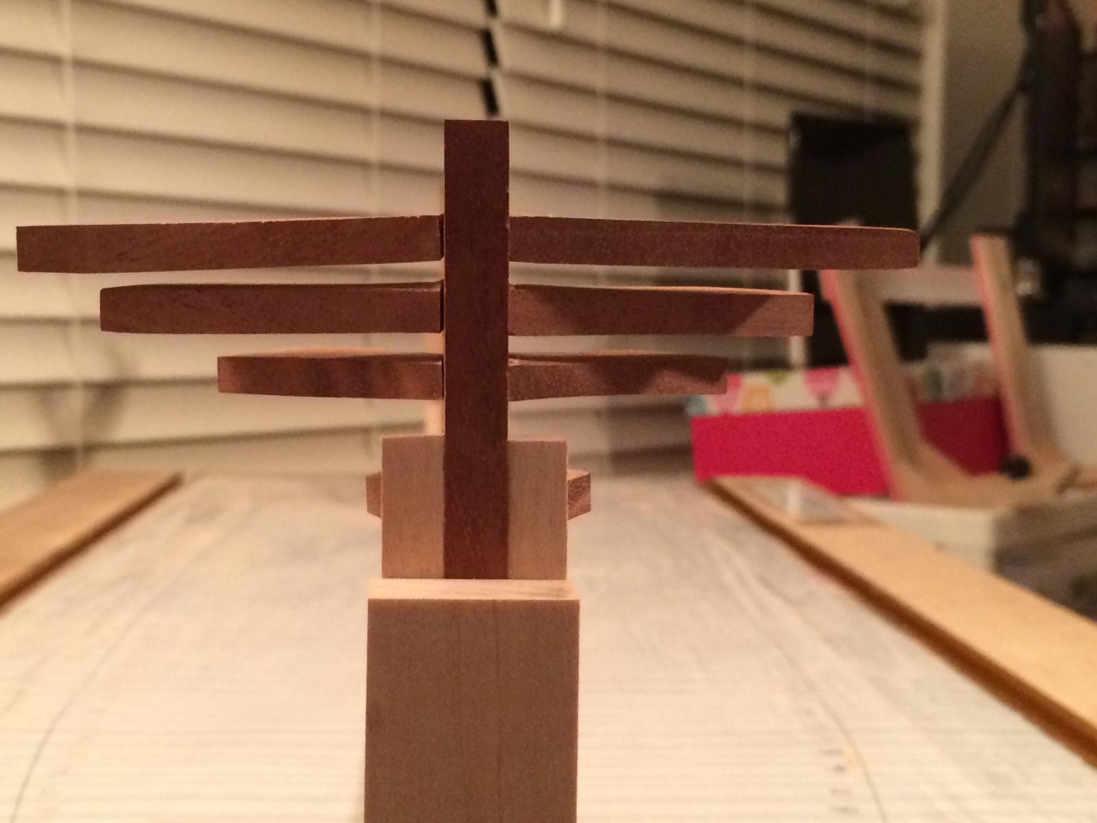
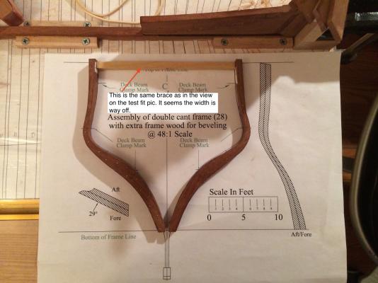
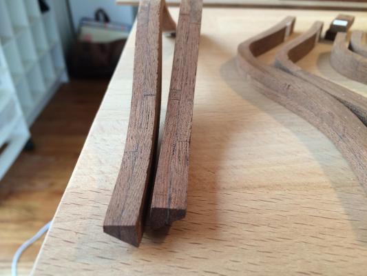
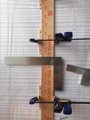
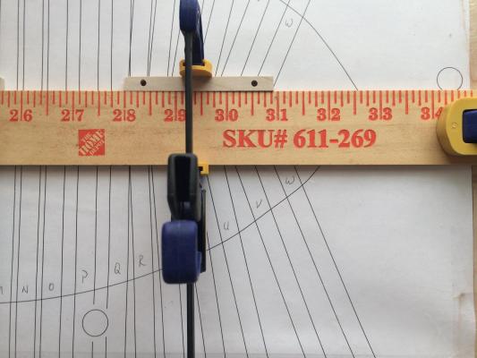
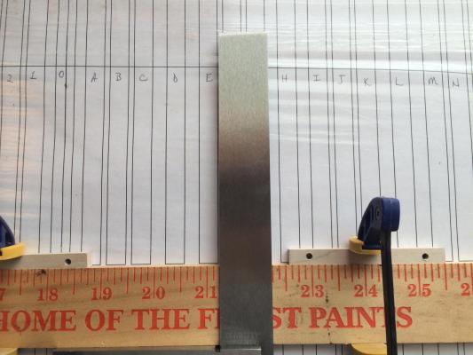
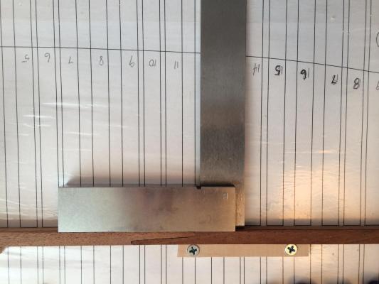
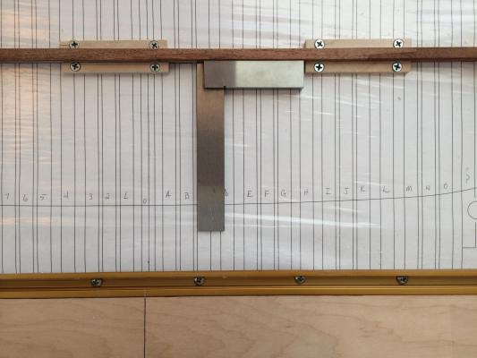
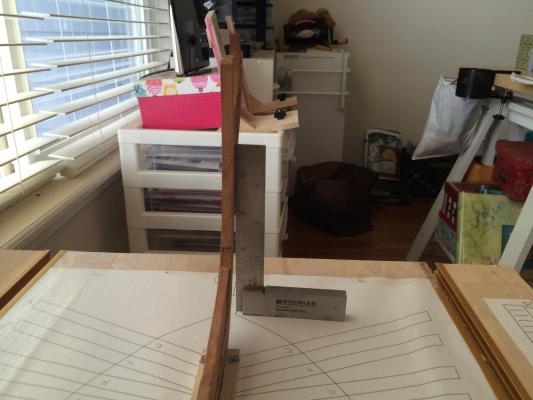
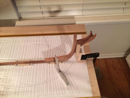
I edited the previous post adding in some annotations on the photos. Basically what I'm worried about is the breadth between the frames. The brace shown was cut to the width shown in the assembly plan for the frames and is the same one in all of those photos.
-
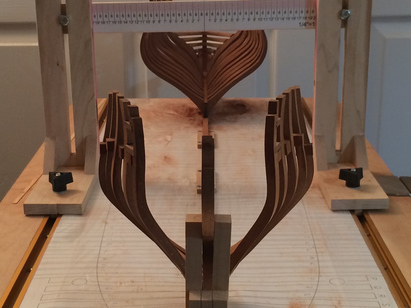
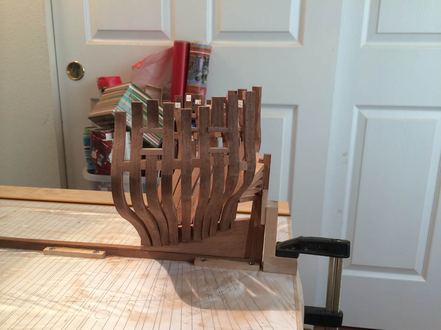
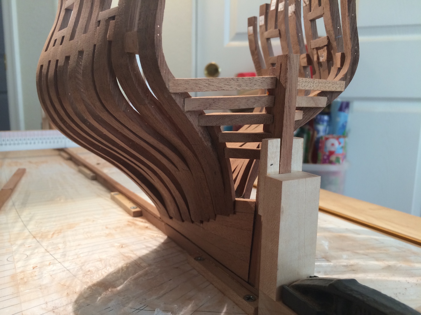
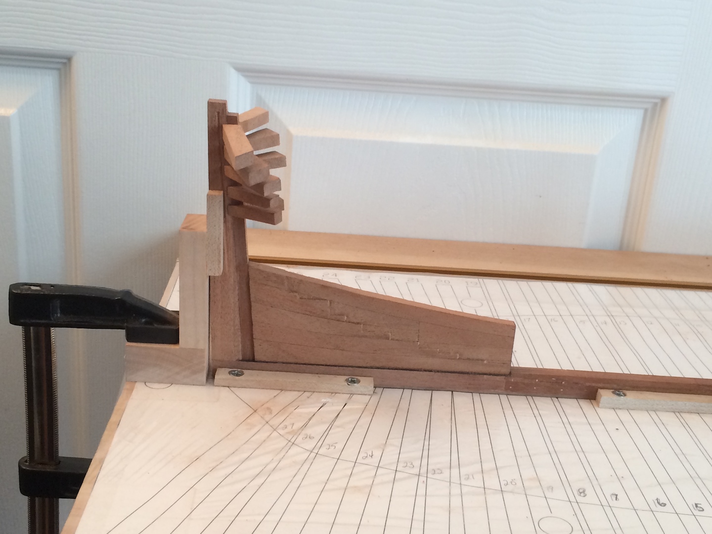
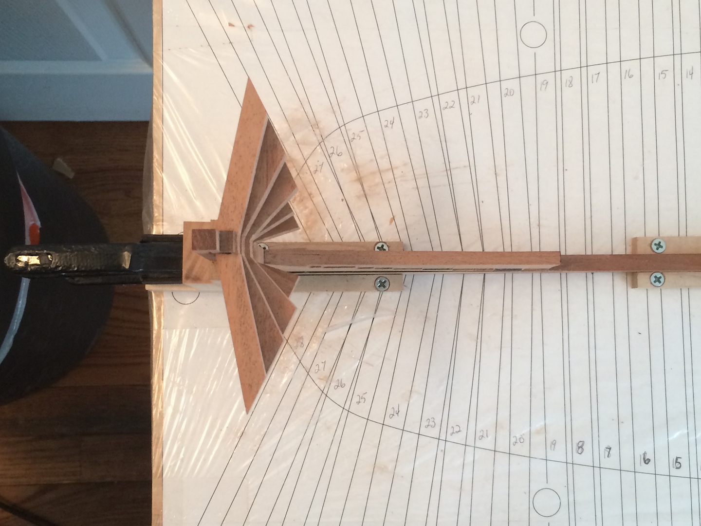
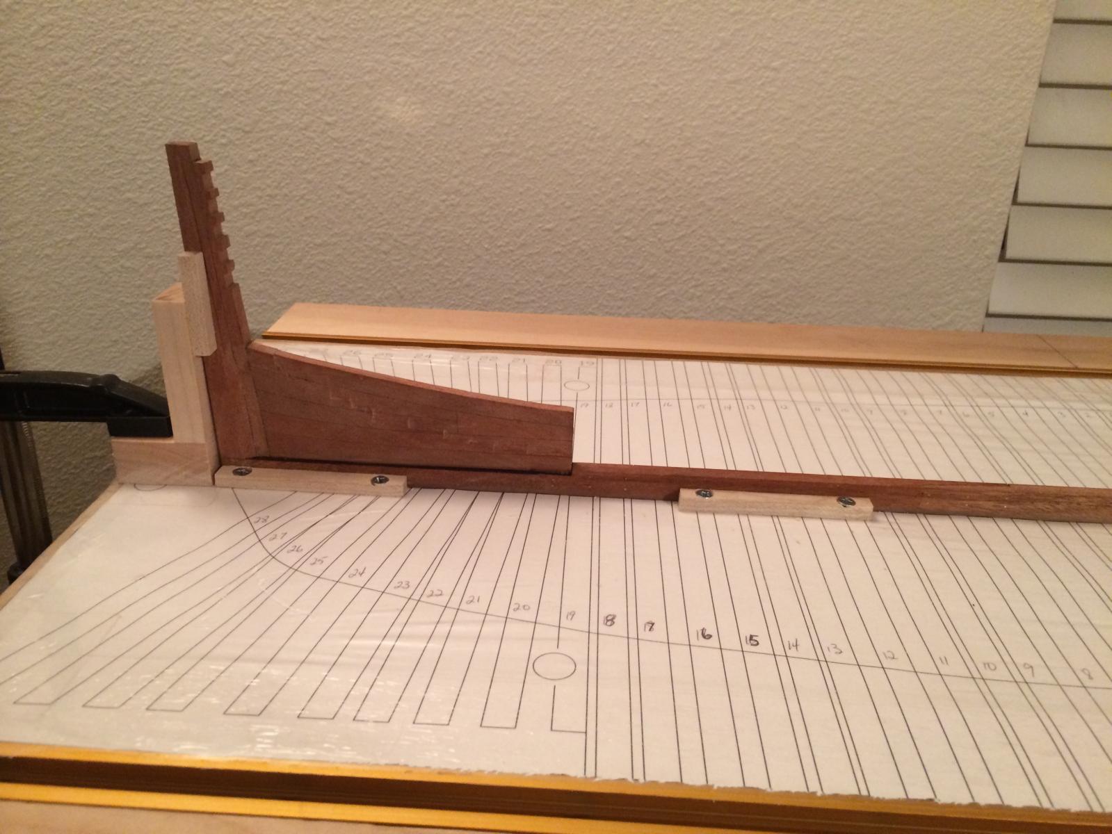
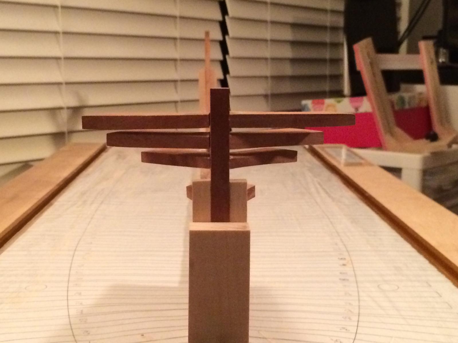
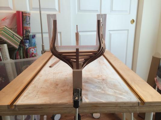
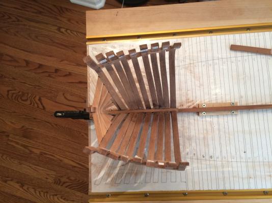
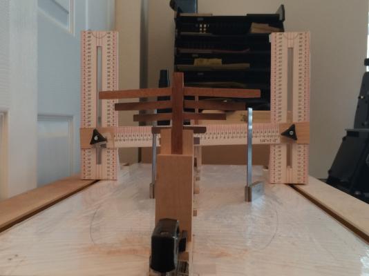
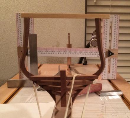
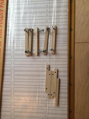
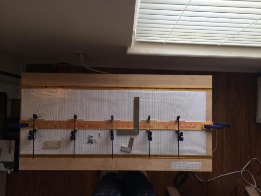
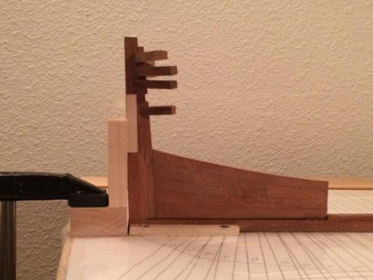
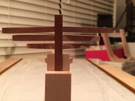
Hi guys, rookie is back again... So, I was all excited to raise my first frame, #28. Got the ends of the transoms prepped and ready to go then came the test fit with some rubber bands and as you can see from the pics, the width is way off. I have no idea where this error came from or how to fix it yet. If I push them out, to get the brace in-between, I won't even be able to attach it to the transoms. What boggles my mind even more, is that it fits fine on the template. Any thoughts or suggestions would be greatly appreciated. I hope the blacking out is ok for the copyright stuff as I don't know how else to get my explanation of the problem across. Thanks in advance guys... View from fore: View from stern: Plan View (assembly)

-
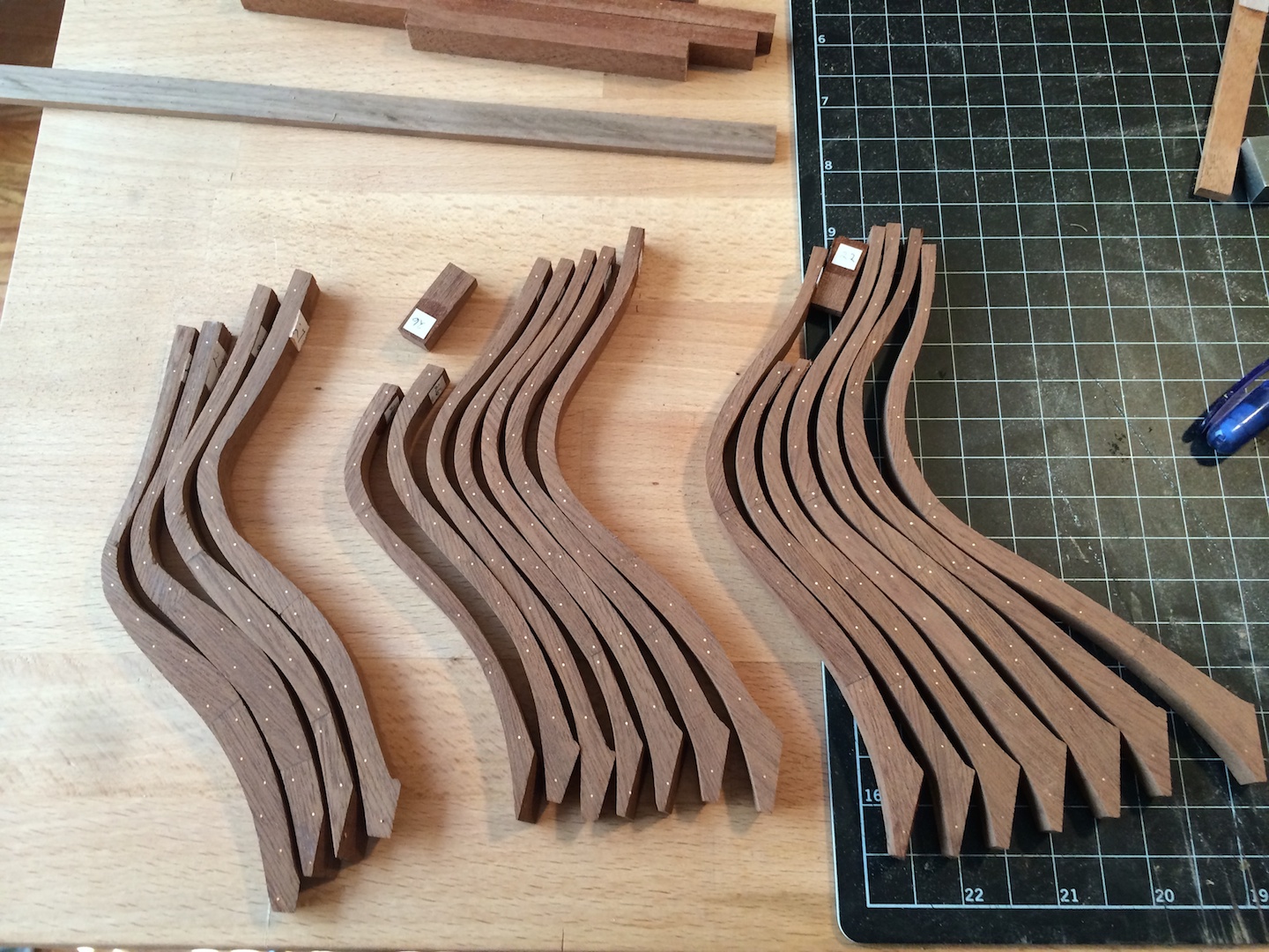
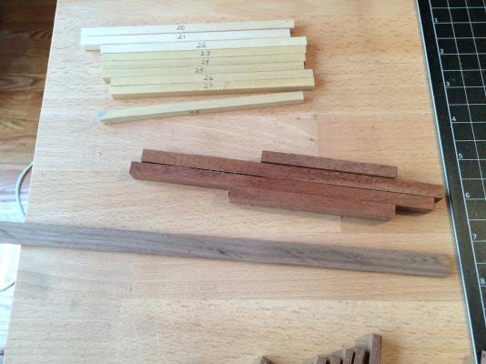
Hi everyone, been a while, but I have also been busy making the aft can't frames and they're ready to start raising. Not to many pics this time around. In one of my research books, it was stated that the frames were bolted with 1" copper bolts and also anchor chocks were placed in-between the futtocks. I did the bolting, but not the anchor chocks on the aft cant frames as I couldn't see exactly how to cut them into the futtocks before I faired them in. I do intend to place them into the square frames though. Next up is raising the aft frames them moving on to the fore cant frames and hawse pieces, then fill in the middle. Thanks to Guy and Daniel very much for the help with the angles, they worked out really well. I'm all set to start raising them. Have some good scrap pieces to make the support block spacers and some walnut for the gunport lintels & sills, and a set of braces for the top to set the correct width. Until next time...

-
Wow, thank you so much for all of that info. It will surely come in handy when I get to that point. Thanks again.
-
Hi everyone! The rookie is back with yet another question... I've started shaping the aft frames that I have roughed out and was wondering about the angles of them. "Common sense" would say they are done on the floor futtocks to get the proper angle. Is there anything weird that I don't know about in the plans on the rest of the frame futtocks to achieve the angles necessary?
-
Richard, Very nice work you have done with the bollards and hawse frames. I can only dream of the day when I am that far along at the rate I'm going. When you made the bollards, did you fit a bowsprit to figure out the angle and placement or was there another source you referenced? Randall
-
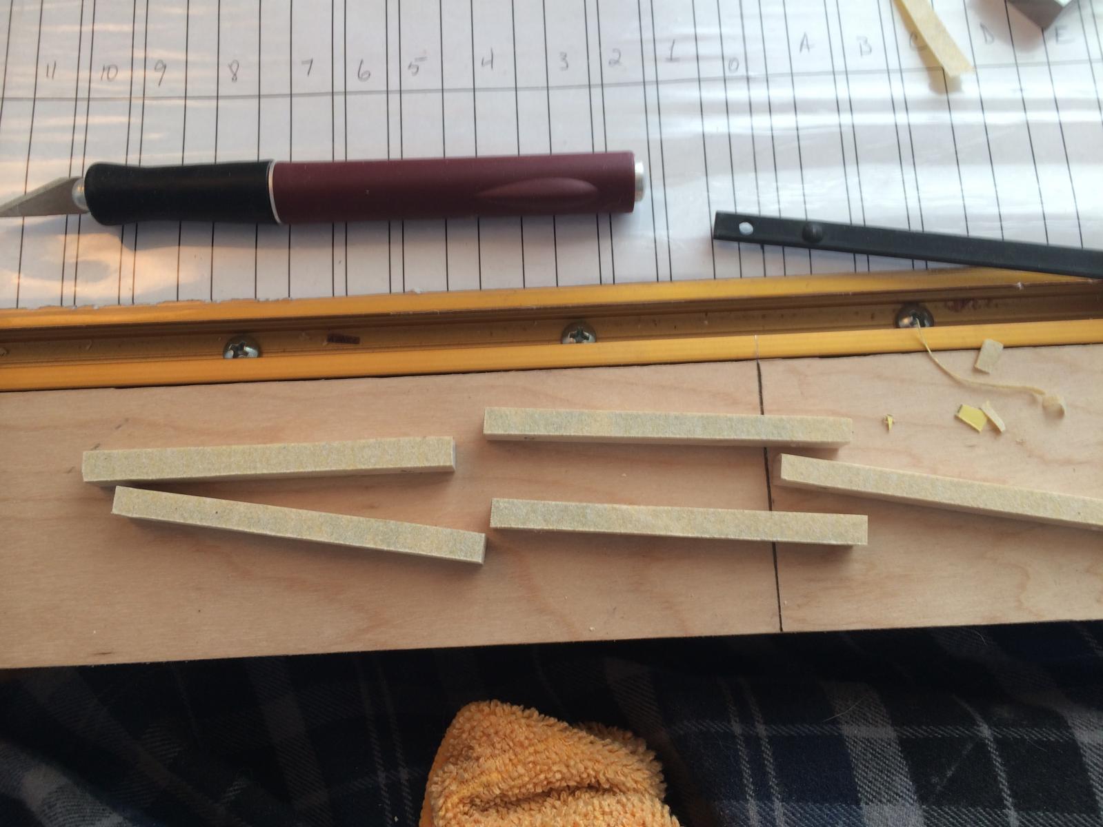
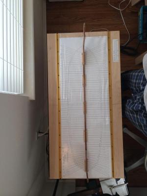
Hi all, back with a little bit more progress... The first set is the mounting to the board to get ready for framing. Since the build board is a pretty good size, I acquired some table legs with locking wheels so I could rotate it around to get to all aspects from any angle. Also, the mounting is set up the same way with as little in the way as possible without compromising security and support for the keel, stem, and stern. The second is the second go with the transoms, they're almost ready to glue in place, plus I have to remake filling #3, that's why it's not in the photos. I broke it in half while I was tapering it, oops. I learned quick not to cut the notch before I shape them, lol. Build board mounting... The transoms, test fitting... Have a good week everyone! Randall


-
Hi Daniel! Mighty fine work, looking very good. It might be a little late, but I use a glue that my wife gave me to try out for my patterns. It's for scrapbooking used to glue photos in her books. The great thing about it is that it holds very well but when your done with the cutting, it peals off very nicely without leaving anything on the wood. It's called Tombo Aqua. You put it on, let it dry a minute or two then put your patterns on. It's good stuff. Then when I'm finished cutting, I just use a little plastic scraper and it scrapes it off in one swipe with nothing left on the wood.