Hellmut1956
-
Posts
74 -
Joined
-
Last visited
Content Type
Profiles
Forums
Gallery
Events
Everything posted by Hellmut1956
-
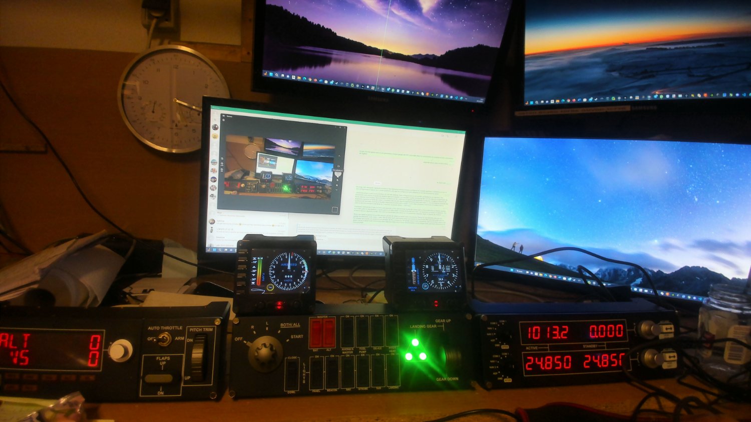
I am still alive and the focus and focus my activities on my workshop. Will write a report soon. This image shows The monitor setup that I have on my "office" desk in my workshop. The reason for this is the help of an old friend with whom I use to fly his real airplane, a Bonanza 35B, in California, Nevada, and Arizona. He did help me to get a brand new PC with an RTX 3080 graphics card and flight simulation peripherals from Logitech. So while I profit from this setup when I return to the electronics in my sailboat model it is also my virtual "cockpit" for flights in the Microsoft Flight Simulator 2020. Also, my workshop has a Creality Ender 5 Plus 3D printer for which I build a platform on wheels similar to what I did build for my circular table saw and milling table based on a Bosch GTS XC Professional and a Triton TRA001: For the circular table saw I build a system to have the altitude of the circular saw disk above the surface of the table. This way I can set the depth the saw cuta into a wooden plate by 1/100 mm presision. I am planing to make the same for the milling table for which you see the opening where the Triton TRA001 is placed. As the Triton TRA001 router is pretty heavy I have to build support that takes the weight of the router. The other related project in the aspiration system for my workshop and to which I have connected the table saw. As soon as I have my 3D printer in shape to be used I will have to print 3D a device that allows the aspiration system to also get the dust that the table saw generates above the saw table surface.
-
Design by Modelling
Hellmut1956 replied to Hellmut1956's topic in CAD and 3D Modelling/Drafting Plans with Software
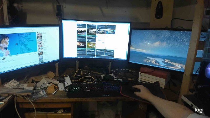
So much time has passed since my last publication. Since when my serious health problems started I have had 5 strokes, 1 full stroke, and 4 other light strokes called TIA, Transient Ischemic Attack, thanks to the tablets I use to make my blood be thinner. The most serious consequences came from a short break my heart took and that damaged parts of my brain. This was due to a side effect my medicine "beta blocker" used to lower my blood pressure. Since then I have had serious problems concentrating over a longer period of time. Here I got a pacemaker implanted and now I am approaching the point in time to get it replaced after about 10 years. But for about 2 years my medicine seems to be properly defined so that I had no need to go into the hospital. But studying the stuff of this thread sadly is beyond my current capabilities. But one thing I have learned is that keep working on my projects, and keep using the muscle between my two ears as my brain reorganizes itself and improves its abilities. So now I am working on my projects in my hobby of naval modelism. But then I had a problem with my fraise and as a consequence, I started to work on my workshop to fix that problem. But with my tendency to exaggerate the scope of my projects, I am working for a pretty long time on my workshop. I will present that work on another thread. Then I succeeded to crash my pc due to static electricity. After some time I had phone conversations and Whatsapp sessions with a good friend of mine with whom I used to fly on my frequent visits to the USA on his Bonanza. He is now also retired and lives in Hawaii. He proposed to use the Microsoft Flight Simulator and fly virtually together as we used to do flying together in a real plane. Sadly I had to tell him that I crashed my PC. So he decided to buy me a new PC so we could fly together. After that for now one year I have been working to get my office desk in the workshop to be a good cockpit for the MSFS2020: So the first image I have attached shows the Logitech peripherals and my 4 displays. As you can see the monitor setup is less than optimum. So I started to look for a monitor that would be my main display for MSFS2020. The Odyssey Neo G8 display is a curved 32" monitor with a 240Hz refresh rate and 1ms latency at 3840x2160 resolution. I got the chance to grab s special promotion and purchased it. So the main display for MSFS2020 would not be my bottleneck. Now the third image shows my cockpit with 3 monitors, each with 3840x2160 resolution and 2 being 28" and onw 32" . What is still missing are my 2 24" monitors rhat I will place above the 32" monitor. While my RTX3080 graphics board con only support 4 monitors I have connected this 3 monitors to it. My CPU, the i7 11700k and my motherboard has 4 Thunderbolt 4 interfaces those 2 24" monitors are taken care of by the CPU with its graphics functionality. That hopefully will happen this weekend. Possible was this thanks to me no being retired and receiving my pension. So with this my cockpit for the flight sim is done as far as the hardware is concerned. I have pending a huge number of projects I will present in that thread I referred to.

-
You are right. Not always what is technically of interest good for the nature. As to your statement about resin printers, I cannot judge it. The filament based printing is a technology for which I have invested by buying a printer and for the purposes I have as of now, it is ideal for me. Having written this, I still have a steep uphill battle to learn its use.
-
I have just received in a newsletter from ALL3DP where this link is contained: (2) PET bottle to 3d Print! : 3Dprinting (reddit.com) I have also chosen one video at YouTube that shows how to make a machine for this purpose: https://youtu.be/ueJXQ7appC0 I found this topic fascinating.
-
The last years I have focused on improving my workshop and that still keeps me busy. Let us see hov the future will go.
-
Workshop Vacuum cleaners
Hellmut1956 replied to DaveBaxt's topic in Modeling tools and Workshop Equipment
I am building a lot of stuff in my workshop. One challenge is to run a 3D printer in the same room I do operate a Bosch 10 XC table saw and an extension of it a milling table. Both are source for lot of dust. So I decided to build a dust collection system based on a cyclone, that stores de dust in a tonne and that keeps the bag of the vacuum cleaner nearly empty. Additionally I am building an air cleaner that collects particles down to 5 micron size. My workshop consists of 2 rooms so the air cleaner is doubling 2 radial fans with 2 sets of filters, one for each room. -
I have used my cyclon based absorption system for the first time and it went well. The new ideas for improvements to my workshop are always flowing and I do try to keep pace in making those ideas real. A video at YouTube showed how to make a system to fight the pollution of the air in the workshop. The system has a filter system consisting of 2 filters set in series. The first one is there to catch the larger particles in the air, like visible dust particles and chips: The filter can be cleaned, regenerated and the filter material is cheap to buy for replacement as this filter will get clogged pretty fast. The second filter is using 2 pocket filters that will catch particles down to 1µm in size. An important aspect of the video was the use of radial ventilators. While they con move big volumes of air they can also deliver the pressure to have the air flow through the filters. Important to be able to use this kind of filter was to find a compromise between how small particles in the air could be catched by the filter and how expensive it is. This pocket filters can be regenerated and so be used multiple times and they are cheap in comparison to other pocket filter supplier products that cost easily 120 Euros for 6 pocket filters. This shows why it is so important the first filter keeps as much parts out of the pocket filters. Different from the radial ventilator the video uses I have decided to buy those 2 radial filters: Both radial ventilators I have purchased and that are due to be delivered on Monday have speed regulators and a small display showing its speed. From first feedbacks I have been getting from forum members in other forums I migged be shocked as I was when I did purchase a 120 litre barrel to mount the cyclon on it. I had no clue and was not aware of its size. The feedback talked about having purchased a 40 m^3 ventilator and how much air it was it moved. Well, having speed regulators coming with the ventilators I will be able to reduce the amount of air to an amount that fits. My reasoning was that purchasing the smallest radial ventilator with a speed control unit and purchasing a big one would make the whole range available to me. The big radial ventilator is planned to be used to free the air in my workshop from polluting particles that cover all the stuff in my workshop and to reduce the amount of particles that could seriously hurt my lungs. This decision was driven because a friend of my son got serious problems with his lungs due to dust. This system that will clean the air in my workshop from polluting particles does reduce the priority to build a cabin for my 3D printer Creality Ender 5 Plus. This is the 3D printer. I set it up by mounting it on the working surface of what I cal my old workbench. I did verify it by making the calibration of the plate and it did work perfectly. i am planning and in the process to build a cabinet on which it and the cabin I am planning to build around so that the old workbench surface is free again.
-
Slowly but steadily I am advancing with the work at my workshop. As building the furniture on which I will place my 3D printer involves drilling holes with a high level precision as to exactly where the holes drilled are gonna be and having had results by doing it by other methods failes to achieve good results I have decided to buy a drilling bench: i had seen a similar drill bench used in a video at the YouTube channel Ingos Tipps about building a bench that added functionality I decided to buy this drill. It uses 2 laser beams to show a cross exactly at the place were the drill would drill the hole. With this I will be finally able to drill the holes exactly where I want them to be. The video from which I took the picture shows in an extensive form the benefits of this bench. I will build it. The other tool I did purchase is this one: On my first use drilling the holes to take the wooden dowels to hold a wooden plate in its position the results were less than perfect. But I think I have learned to be able to use it better. The drawers im am going to build for this piece of furniture place a bunch of challenges to me. One is to drill the holes for the wooden dowels as precise as possible so they fit into the holes I will have drilled into the MDF plates. Here I believe starting by just drilling the holes for 4 dowels at the corners of the MDF plate, so that I can fix the plate into the right position and than drill the holes for the remaining dowels. But the challenge is that I need to fix the MDF plates for all drawers in their right position, as It gets more and more challenging the less vertical space is left. The other challenge is that the wooden dowels at the center vertical wooden plate need to be used for fixing the plates on both sides of the vertical plate. How do I get the plates on the right side to take the wooden dowels at the center board. Still an open question for me. And finally there is an experience I did gain when my old workbench had a huge drawer. The result was that in that drawer stuff ended up piling itself in there without order. Due to this experience the drawer will only be half as deep the length of the width of that furniture. Si I have the option left for the future to add drawers from the other side. Finally I want to present you with my personal extension to the lateral support that is used both for the router table side of the bench and for the circular table saw on the other side. I have been so pleased with the Bow Feather DUO, the green parts you can see on my last picture of the router table. I have purchased a second of this feathers and I have purchased an aluminum plate that is like the 2 halfs of the lateral support for the router bench, but 12x80 cm long. So I can fix the feathers there in the same way as you can see on the router table side. It looks like soon I will be able to operated my cyclone based dust and chips absorption system with my table saw. Its really just the beginning, but as my 3D printer becomes available on his new desk I will 3D print the missing adapters.
-
So far I have thought the use of 3D printers for naval modelling is an uncharted landscape. This thread has convinced me I was wrong. Simply amazing what has been shown in this thread. I am about to start to go into 3D printing and I have purchased a 3D printer, the Creality Ender 5 Plus. I was convinced that having a 3D printer is of benefit by seeing in YouTube videos how a circular table saw could be calibrated by using 3D printed parts to fix inaccuracies of the elements of the table. Additionally I saw what a good friend of mine did for me by printing parts I need to implement a cyclone based dust and chips absorption system for my workshop. But I o confess, 3D printing and the related DIY CNC milling machines have become a hobby for me by their own merits. Right now I am improving my workshop to integrated a circular table saw and as an expansion of it a router table. Only when that projects are advanced enough I will be able to make a cabinet on which to place my 3D printer and to make to mutually contained cabins in which I can isolate the contaminated air from my other machines and the high humiity level in my workshop. I do repeat the statement now for my workshop. Improving it has become a hobby by its own merits.
-
Here ist the plate I did purchase from the company Sauter. They deliver wooden boards to be inserted into the Bosch table saw GTS 10XC. The version that I did purchase is the most expensive one because I did want it to show the same color as the table saw shows on its desk. The grey frame you can see placed within the opening of the board is made of aluminum and it is there so that the aluminium plate that will cover this opening can be made 100% aligned with the desk surface. This alignment and calibration word is key to enable me to get perfect results when using either the saw or the router. here you see my table saw with the board inserted into the desk of the table saw by extending the surface of the saw to the right. Another detail I want to highlight is the element of the table saw that is with a white board replacing the aluminum red colored board with which the saw was delivered. This table element is rigid and mounted on the structure of the saw without it ever changing its alignment. This element is the reference to which all other elements of the table are aligned with. The wooden board that has been inserted into the surface of the saw is aligned together with the right most element when fixing the screws of the right most element. So as you see the table on this foto it is perfectly aligned to the right of the longitudinal support of the saw. Here the link to the page where this aluminum plate could be purchased with more details of it. The version I have purchased is the one prepared to be placed in the opening of the wooden board and it has the perforations so that a TRITON TRA001 coul be mounted to it. Here you can see the aluminum plate inserted and calibrated into the desk of my table saw. This is my router TRIOTON TRA001. Here you see my router hanging from the blue aluminum plate. Not because the pressure the supports that prevent the side with the router table functionality bend down my desk surface due also because the router is pretts heavy, I did build it this way because I did like it. This picture shows with an acrylic plate how the router is mounted to the plate, which in my machine is this blue colored aluminum plate. The silver colort insert is to adapt the diameter of the opening for the milling head that will be used. You canalso see the handle, which inserted in one of the holes of the blue aluminum plate.. Turning it you can set the heigth of the milling head above the router table. I plan to use the same kind of digital display so that I can read the heigth of the milling head above the table surface. But I did further improve my equipment. I did purchase an upgrade for the longitudinal support of the table saw. This upgrade consists of 2 aluminum profiles that can be moved closer or more distant from each other to make the opening between the as narrow as possible for the milling head that will be used. In this picture you can see a silver colored box that is between the original longitudinal support of the table saw and the aluminum profiles of the extension for the router table. To this, at the back of the machine from this perspective, you can connect a flexible tube from the dust and chip suctioning system. Also the milling process of the router generates a lot of dust and chips. Having an opening exactly behind the opening for the milling head of the router dust and chips can be absorbed where it is generated. But this also shows you that connecting this combined circular table saw and the router table requires the suctioning system to have at least 3 ends connected to the machine. Working with the circular table saw or with the router has taken the fingers of many operators when they were not concentrated enough on what they were doing. Even my families requires me to spend as much effort as possible to prevent me from getting hurt. Again, the videos on YouTube are an excellent source for information. Even more by studying all the material about safety when operating this machines I even learned to understand for what was the acrylic transparent part mounted across the 2 aluminum plates. This element has a surface that will be placed so close to the object being milled, that if the operators fingers slip, they will nit slip and get in touch with the milling head. The other issue I did learn was related to the width to which the 2 plates are away from each other. As the work piece has to always be moved from the right to the left, if the opening is too wide the milling head can draw the work piece into the opening, as the milling head always moves counter clock wise. Here the Link to this feather board from Bow I did purchase from Dictum. As you can see in this foto of the router table side of my machine I have mounted the feather shown on the pevious picture to the lateral support upgrade for the table router. The feather on the right pressures the work piece to the support and the feather mounted on the left presses it onto the table surface. By the way the feather on the left I did install in the wrong direction. So while the feathers keep the work piece presed into the trayectory desired it also has a safety aspect. Work pieces can kick back and hurt the operator. Having the 2 feathers mounted on the right side they also make it impossible for the work piece to kick back and also that the work piece is drawn into the opening of the support by the milling head. I did like this so much that I did purchase an aluminum plate like the ones used in the extension of the lateral support on the router side, but 80cm long to upgrade my lateral support on the table saw side so that there also the feathers could add to my security. This 2 grips do help additionally to keep my hands away from the blade of the table saw and the milling head of the router table The tool shown on the second picture explains itself. The one on the first picture is of use when you want to cut with the blade of your table saw a board on its narrow side, same applies to the router table. A victim board is used to move a board on his narrow side and keep it perpendicular to the direction that is being worked on. Having learned so much about calibrating and aligning parts of the table saw by watching the videos on the Youtube Channel of Nachdenksport and having purchased quite a few of the products that he develop and demonstrated in his videos on one side and having a very good friend of mine print me 3D printed parts for my dust and chips collection system for my workshop, I was finally convinced that 3D printing would be very usefull for me. Not just while working on improving my workshop, but also for my sailboat model, the Carina. Thanks to the "Black Friday promotions" I could purchase the Creality Ender 5 Plus 3D printer for 50% of the price I have seen it recently offered. 3D printing is a science of his own right and I will present to you my printer, the cabinet I am building for it and write a couple of things related to the 3D printing. A challengue for placing my 3D printer in my workshop is the air polution due to dust and chips resulting from using other equipment in my workshop. My wife has place a strict veto onme to expand my workshop into other rooms in our house.
-
A lot of time has passed since the last time I did update my thread about my workshop. Health problems are slowing down my progress, saving money to be able to buy what I was tempted to buy and finally waiting for promotions like "Black Friday" added to it. Listening to videos in YouTube, reading material related to topics I found to be interesting for me in those YouTube Videos and finally reflecting about those potential purchases and their integration into my workshop. So the first piece of equipment I chose to buy after comparing possible alternatives was a circular Table saw. I decided to go for the Bosch Professional GTS 10 XC: The key criteria that make me decide to buy this circular table saw were: 1. The precision of the longitudinal support. Many of those tend to result in having a different distance to the circular blade. The one of this machine corrects its position thanks to the way the fix on the back side of the support works. It get the support to be parallel to the blade. 2. In a German YouTube Channel called "Nachdenksport" the person running it intensively studies aspects of how to optimize the aligning of the table elements. He offers numerous stuff 3D printed that make possible perfect behavior and alignment. 3. The table of this circular table saw can be expanded to include a router table. Numerous expansion options get me as a result a piece of equipment that combines a table saw and a router table. Equally relevant becomes the issue of absorbing the dust and chips originating in the use of this equipment I am designing a system for my workshop, where the dust and chips from ideally any machine I use in my workshop dust and chips will be collected. This graphic shows the principle of such a system using a cyclone to separate dust and chips from the airflow that is being collected from any machine that will benefit from such a system. The polluted air with dust and chips flies into the cyclone horizontally and will spiral in the cyclone. The polluted content of the airflow will fall down in the cyclone and drop into the barrel. The air, now much cleaner will be collected vertically from the vacuum cleaner. The benefit is that a very little amount of the dust will be collected by the air filter and the dust that gets into the bag filter is going to be minimal. This the filters in the vacuum cleaner will remain empty and the suction capability of the vacuum filter will not be reduced. You might guess the shock I had when the barrel I did purchased arrived. Knowing from reading in forums and seeing videos in Youtube, the barrel can implode due to the reduced air pressure within the barrel used. To prevent this from happening to me I ordered a metal barrel and I did chose one that had 210 liters of capacity. Well, assuming I do live for another 2 decades that barrel will never be filled! This is the industrial vacuum cleaner I did purchase. Here the box with my circular table saw finally did arrive. I used the "Black Friday" promotions and got the saw for 50% of the price it was offered at Amazon a month ago. When with a lot of effort I was able to put the box on the surface of what I call my old workbench and this was what I saw first opening it. Here my circular table saw placed as desired on the old workbench. As you can see in this foto the desk surface consists od a good number of elements which all have to be aligned properly. The hole in the surface is were the red piece of aluminum shown on the last foto is placed and the blade will be visible there. I also did purchase a second blade for my saw. Studying videos on Youtube I started to learn about how to use such a saw, what are the sources of danger in such a saw and how to eliminate this risks as much as possible. But I also did learn about what it means when the saw does its job along the direction of the wood fiber or across. That the distance between the teeth of a blade has to take into account the length of the chips that happen while the blade does its job. So the number of teeth of the blade that came with the saw was 24 while the second I did purchase had 64 teeth. The first blade is good when the chips are long and the one with more teeth when cutting across or when the material being sawn did not generated long chips. The groove you can see on the blade with the many teeth is to eliminate or reduce the vibration while cutting. In a video on Youtube I took this image. It shows the desk of the table saw to be expanded and achieving this way to get a router table functionality added to my circular table saw. But I also got a view of how a wooden cabinet on wheels could look like that also included supports to prevent the table on the side of the router could bend itself down due to the weigth of the router. I decided to make it, or at least similar. Here my cabinet while in construction. You can see the big openning on the top left of this cabinet. While the circular table saw cuts a lot of chips and dust is not collected by the dust and chips suction port of the saw, but drops to the bottom inside the table saw. . In this foto you can see my circular table saw from below. The grid that you can see is how the table saw allows chips and dust to drop out of the body of the saw. Here the same view, but now without the grid. The shape of its opening is the shape of the opening you see on the wooden top side of the cabinet. Additionally you can see the black box on the left side of the opening, this is the motor and the aluminum case to its right is where the blade is, On a Youtube video on the channel "Nachdenksport", sadly only in German, a digital sensor is added to be able to display how much the blade will show above the surface of the table saw. Here you see my circular table saw mounted on the cabinet in construction so that its opening at the bottom matches the opening in the cabinet.
-
Really, the responses I received from al of you are the most valuable for me. Thx once again.
-
I want to share with you my results in looking for a solution to my question. Apparently none of the standard documents include a definition about how the kind if bit and its size is defined. But I found a website in German language where there are displayed in tables the relationship between the kind of bit and the diameter of the screw with the size of bits associated. Here some first data: Torx: Cross recess screws: So far I have not yet verified in practice the information in this 2 tables, but of course I will do it as a prepare the labels for the glasses. Phillips bits also exist as PH00 and PH000 but the website states that there is no data about those sizes.
-
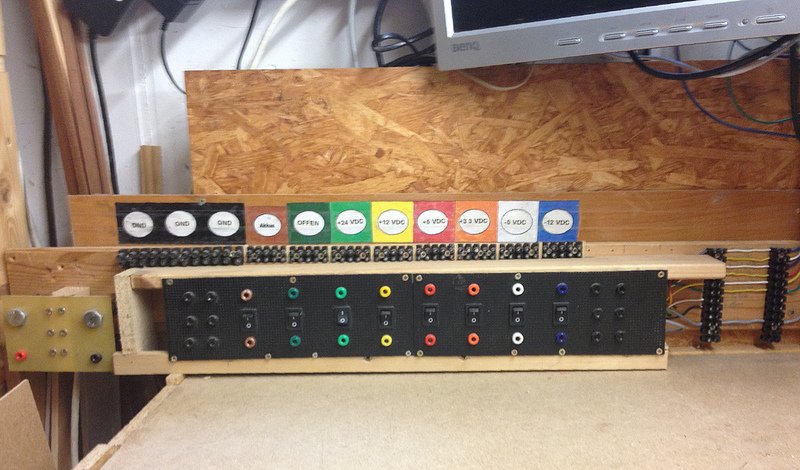
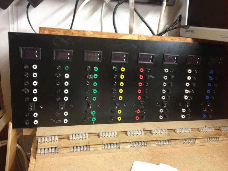
Thx for your responses! My question was exclusively about a place where the information can be found, if it exists, from the image of a screw head to identify the size of the bit for it. To identify the kind of bit I have proven in my first contribution to this thread how PH and PZ can be identified. To the very valid question if this is not over-engineering, I am rebuilding and organizing my workshop and screws, washers and other pars will all be stored in glasses and labeled as shown in the picture above. This pictures dhows one of my 3 workbenches in my workshop and on its surface the glasses and bulk parts I am sorting and labeling. I do not do this work for living but for fun. I do not have a photo yet about a drawer organized to have all kind of bits well identifiable. But as an example I want to show you one of the drawers and how I have organized things in it: For me there is a beauty in having stuff organized as the ones on this 2 pictures. The other important reason is to see at a glance what options I have on a kind of parts and to see if anyone of those have not be put back to where they belong. Or see how I keep improving stuff, in this case my power supply panel on my electronics workbench. The first picture shows what I call panel 2nd. Generation, On the right side you can see that I have bridged the cables that connect to my panel and where I want to place electronic fuses I am to build using Mosfets. The second picture shows my 3rd. Generation panel with work on it in progress. The reason for the mayor update was that I found this little displays that will show voltages and the amount of current flow and that require a completely different wiring. Also here, the reason for this was the fun of doing it and the later joy of having it available. So I find it interesting that so far apparently nearly anybody has dealt with the issue of identifying the bit size from analyzing a specific screw. The best so far is the link to a table where bit size is put in relationship with screw diameter.
-
@Bob: The website you supplied the link to is the closes I have seen so far to what am looking for. But if I have not misinterpreted it, it gives information about the physical dimensions of the bits. What I am looking for is information about the physical dimensions of the recess in the screw heads that would allow me to identify what bit a certain screw requires.
-
I am contacting you with a question that results from my work to get my workshop organized. I have a huge amount of screws and other stuff and I am working on placing each type of screw into its own glass: A first version of the label design I am going to use for the purpose of identifying the type of screw and the type of bit. So here it is a countersunk screw 3x16 mm size and the thread is for use with wood. The proper bit is PZ 1. Here it was simple as the screws were still in the box from the DIY shop. To identify if a screw has a Phillips head or a pozidriv is simple by looking onto its head: This is a pozidriv screw head. Here comes my problem: When I take a screw I can identify if it has a PH or PZ screw head, but not the right sized bit f the proper kind. The result is that often my screws and my bit used gets damaged. By writing the Bit type and size on the label f each glass I can be sure to have identified the right bit for it. By the way I am also organizing to have my bits stored in a way that I can easily and immediately take the right bit. I have searched in the internet for information about how to identify the size of the bit type required and have had no success. May be one of you knows where I can get this information. I guess it will relate the physical dimension of the screw head plug.
-
Hi my friends. It has some benefits that I am not progressing with building my sailboat due to health problems. reflecting things about the design of the sheet control system presented here made me aware of an aspect that could be addressed thanks to the intelligence of my sheet control system. My sailboat model shown in the photo has beams on main and fock sail. I do plan to be able to fully open the sail, 90° to the hulls main axis, to fully benefit the wind coming from the rear. But this has a problem! The beams would touch the water surface when the hull gets away from the perpendicular position. So opening the sails up to 90°, as it is my objective, I do need to ensure the beams do not touch the water! So there is a maximum inclination degree were the beams touch the water surface. So my sheet control system has to take this into account by having a sensor that keeps track of the inclination. The input from this sensor has to change the maximum allowed opening, which usually is managed by the position of the associated stick on the remote control, to ensure the beam s do not touch water! As you can well imagine, the stepper motor used as winch has no problem with this duty, the computation in the microcontroller to monitor the inclination sensor, is also fast enough. But what is with the mechanical part of it? How fast is it possible to pull in the sheet to pull in the beams? Here experimenting will be key. But also intelligence might be able to include what is inclinating the hull and ensure a maximum pull speed is being taken care of. The cause can be either the operator deciding to change the direction the boat boat is navigating or a change in the direction of the relative wind angle is. In both cases the intelligence and the mechanics of my sheet control system can and has to ensure the inclination of the sailboat does not result in pulling in the sheet faster than the maximum speed to be defined. Fortunately acceleration and angle sensors are cheap and extremely powerful thanks to their use in smartphones. I know, my sailboat model will, with a very high probability, never finish and sail before I die.
-
Another project pending to be completed is the next generation panel for my workshop: This is what I do call may Panel 2nd Generation. Above this panel you see the little displays I found at a Chinese source that do display voltage and current values. I thought it would be great to have one of this displays for each voltage my panel is supplying. What I learned later was that to have those displays show the current voltage and current for each voltage supplied by the panel I had to implement mayor changes. I do not enter in details as this goes pretty deep into electronics. What you can see is that now each supply connectors now consist of a pair of connectors, both poles. You can also see the switch available at each voltage source. I am replacing them by ones that do emanate red color light when in the "ON-Position". To the right is the opening for a 5 mm diameter RGB LED which will be configurable remotely. At the top you see now the small displays were they belong to and at the bottom screw able connectors. Both them and the connectors above the switch are switched ON/OFF by it, the 2 pairs below the switch are constant ON ones as soon as I switch my modified PC power supply to feed the panel. As it happens usually one change leads to more changes. I have to develop and make small PCBs to have the circuitry to feed the RGB LED.: Each of the 3 pins to control the color that will result displayed from the LED next to a switch. You can appreciate how small those surface mounted resistors are. Each one of the 3 pins of a RGB LED are driven by something called PWM, pulse width modulation. This is used to control the amount of current flowing thru the LED. 8 RGB LED, each with 3 pins that require a PWM to control the amount of current results in 24 PWMs. This board contains an IC, the PCA9685 that is capable to generate 16 PWMs. So 2 of this boards, total 32 PWM are required to generate the 24 PWM I do need. This small RaspBerry Pi board, its latest revision offers WiFi and Bluetooth connectivity. It will program the 24 PWM so that each RGB LED displays the color code related to the voltage being supplied. I will be able to define and change the color of each LED from a window on my PC that shows the Linux desktop running on the RaspBerry Pi. As you can imagine, the delay of my ability to work also on this project due to my health problems makes me angry with myself and it has to be the resource to overcome the limitations due to my health problems.
-
@Big Rat: I need to revive my enthusiasm to research, experiment and to work on improving my workshop. Regarding AI there is a development to implement what is called "Neuromorphic System" The company BrainChip has developed the functionality into a device called "Akida". This works in a way called pulsed and makes it possible to implement in devices connected to the Internet, called etch devices, to run AI acceleration which is orders of magnitude more performant than existing implementations and demands less power, again in the order of magnitude. I guess phones that have this kind of accelerators for AI will begin to be available in 2020. So I am in no rush!
-
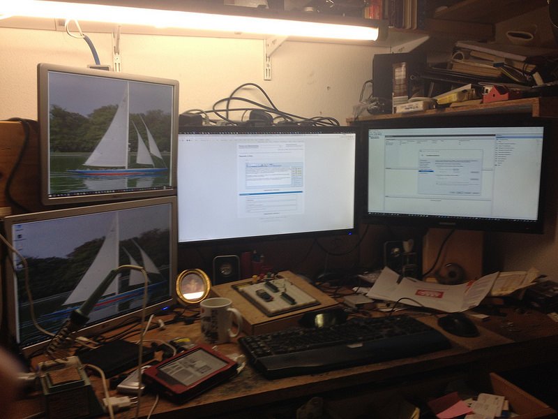
Finally my values of sugar in my blood is getting fine. Sadly the health problems have revived a bit the problems I had after my heart did stop a couple of times. After a while my brain tells me it cannot continue. I also have problems self motivating myself, something that wakes up my will to fight against those limitations. What I usually do in the morning is getting into my workshop, go through mail and then play some games on my computer. By now i am bored about playing those games and so I am forcing myself to continue work to get order into my workshop. What I am proud about are the improvements at my workshop office space: My graphics board in my PC, GTX1060 with 6 G Byte of memory, is no using 4 monitors connected to it. The lower 2 are 28" UHD monitors, the upper one on the right is a Samsung 24" monitor, the one to its left is a 23" monitor, Additionally I have purchased and connected the Logitech Z607 5.1 Sound Boxes. Was not trivial but finally I got it done!
-
Just coming back from a stay at the hospital for a week due to diabetes problems. This stay was useful to read, was useful to reflect and to think about the possibilities to apply what I learned in those readings to my model. 2 "topics" did come out of this exercise. One was the possibility to create an Alexa speech interface with the electronics in my model. The other one was to investigate if artificial intelligence could be applied to my sheet control system. Both of this activities do require to think about what, how and if meaningful it is to apply this. So for the Alexa interface, voice interface does require to think about where such an interface would look efficient or at least funny. So i.e. setting up the model at the shore of the pond or during the tests in my workshop. This does require quite a bit of work to analyze it. The use of artificial intelligence as part of my sheet control system requires me to reflect what "inputs" would be valid and against which the AI would do the fine tuning of the sheet control system. Another 2 true inputs are the position of the control stick on the R/C transmitter that defines what is the maximum angle of opening the boom is allowed to have. The other valid input is the one coming from the magnetic angular sensor keeping track of the boom. This is the true actual angular position of the sail. The use of AI requires to have a lot of information, called datasets or examples, to train the AI algorithms. As my sheet control system uses a couple of electronic sensors, each of them can generate thousands or hundred of thousand data points as the sensors do provide data to the system at pretty high frequencies. It is relatively simple to generate those examples in my workshop, as a ventilator would imitate the wind and apply pressure to the sail. The challenges related to this concept are on one side related to identify the different possible or likely scenarios and as a consequence the type of actions a KI would have to do. The other side is to think which method of AI offers the functionalities I want. One aspect is that the AI should continue to learn when rolled out. So I am planning to define and specify what I want the AI to do and what data points are available so to identify which methods of AI could be appropriate. With this, I want to ask in AI related forums for support.
-
Need Advice
Hellmut1956 replied to GeorgeJure's topic in Painting, finishing and weathering products and techniques
Here some photos that show what I write: This photo shows the hull I made using cheap pine wood as it has visible grains that make the wood look nice. To make the wood used visible requires to work details so that no filler is required. I did use 5x3 mm pine wood laths. In this picture, you can see that I was able to remove all frames so that I was able to apply fiberglass with epoxy. Up to 100gr per square meter, you will not be able to see the fiberglass, even where patches overlapped. The result, in my opinion really beautiful, requires sweat, perseverance and exhausting preparation! The hull in construction! My son and I did the sanding. We did it beginning with on side and the on the other side. The second side resulted in an improved surface, so we repeated the exercise on the first side. It was an iterative process until we were pleased with the result. 3 mm thickness of the lathes proved to be a good choice. After applying the glass fiber with epoxy and a special wood hardener, polyurethane clear coat. We started using a 5:1 mixture with thinner so that the coating penetrated the wood. We repeated this exercise after it dries and is sanded carefully with the same mixture until the wood felt hardened, 2-3x, it depends on the wood. then we added a coating 3:1 mixture with thinner, also 2x and finally the polyurethane with no thinner. Between application, you have to keep sanding it with always increasing finner sanding paper. Do the same inside the hull. A lesson I learned: Always work symmetrically. When you have finished the work on the outside, do the same within the wooden hull. An effect of this is that water that will get into the hull will not affect the wood as it is completely sealed by this coating, assuming you did not sand all cat away! Still then, the coating will have penetrated the wood completely sealing it from the water! But when coating it with glass fiber and epoxy this symmetrical coating of the hull from outside and inside. It will prevent those laths to be identifiable when moving your hand over the surface! I did learn in the hard way as I could not believe those wooden laths so thin after sanding that you could see the shadow when moving your fingers over the surface. Now a principle to get deep into your brain: Every effort that you spend on a phase of the construction saves 10x the effort to fix it later. The plan that I had was the copy of a copy of a copy! I do not know how often it was copied! So to make the frames my son and me passed the measurements on the plan to a paper with mm-grid. I do not have photos showing it. But we used different techniques, one after the other so that all lines did have a smooth curve. We started passing the data into an excel sheet and fixed the dimensions so the resulting curves in the chart were smooth. Then we applied a long wooden lathe with homogeneous grain and forced it to the curves on the millimeter paper without bending it over the length of the hull plan just bending it from its endpoints, about 15 cm over the hull length. The result of this effort is that later the resulting curves are smooth without apparent "elbows"! What gets lost when looking on this photo is that each frame picture includes the separation "ears" that place each frame at the correct altitude. The wooden table is a parallel surface to the resulting waterline of the frames. You can see 3 photos earlier that I do use those "ears" to screw the frames onto the wooden table. One last suggestion: I did use 5 mm thick wooden plate to make the frames and I did use a kind of a triplex that is very brittle. The result of doing so is that using a plier I could remove the frames so that I got the inner side of the hull fully accessible without the frames interfering. See the photo of the inner side of the hull. The white marks are the place where the frames used to be. As I did use glue to glue the lathes, on by one and always 1 lathe on one side of the hull, then a lathe on the other side of the hull. Clamps did press each lathe at it was glued to the previous lathe. As the frames just were about 1-2 cm wide I could also use clamps to press the lathe to every frame along the hull. Here you will appreciate the effort taken to have smooth curves for each lathe and the effort to have precise frames. You will need no filler to get a perfect shape of your hull. What I would also do differently if I had the chance to build a new hull, I would use lathes of the kind of wood that results to have the color you want. Here you can see how adding toner to the epoxy coating I got the color I wanted. Another advice should you make a hull as heavy as mine will be. Place a steel lathe on the bottom of the hull near the point where the rudder is placed. Wooden lathes cannot with stand the stress of a heavy hull. So in my hull the steel part is not visible from ourside! -
My health problems are continue to delay my work on my workshop and ultimately on my sailboat model, the Carina. So just a short update: As you can see, hopefully, in my first foto in the attachments, I have upgraded the office space in my workshop. I have a graphics card, GTX1060, which allow me to use up to 5 displays at a time. Here you can see the current 4. Additionally I have purchased an ACER 4K UHD display that has a resolution of 3840 x 2160. it is the one in the middle. I also purchased a new webcam, the Logitech BRIO 4K Streaming Edition that can record up to the same res as the display. Unfortunately as of now I can only take fotos with a resolution of 800 x 600. I have further worked on my panel in my electronics workbench. While what I call the Panel 2. Generation: The initial reason to make a Panel 3. generation were small displays I found that display voltage and current. So I wanted to add those displays to my Panel. As usual you run into quite a number of surprises. To fix those made me make strong changes to the previous version of my panel. One problem is the size of those displays. They do not fit in "one level" above the corresponding receptacles for the 8 tensions offered by the panel! Another problem was that the displays measure the current that flows at each of those 8 tensions through the receptacles via the "Ground" line and is placed in series with the receptacles. So one "Ground IN" and one "Ground OUT" line. This has the side effect that I need to change the principle of my new Panel and have "pairs of receptacles" both for the kind of receptacles you see in the foto of the old panel, as well as for the screwable connectors that you can see at the top of the old panel:
-
@pompey2: Whatever i engage with I do it in the extreme way I always do things. The reasons to work on improving my workshop were this: 1. Due to not working anymore and still too young for retirement the lack of financial resources forced me to organize my workshop so I could find what I knew I already owned. Before this I preferred to buy something a second or even more frequent times. 2. Getting angry with myself of not finding what I was looking for I decided to fix this. 3. My fraise got damaged and to fix it i need empty working surface on my workbench. So I decided to have this principle force me to get my workshop in order! Right now I am having again problems with my help that are keeping me from being concentrated on stuff I do. It is this deficit in concentration and the frequent being tired so that I do sleep far too much that is putting pressure on myself to overcome this!
-
The next advances that finally have let my family members and our friends to confirm that for the first time advances were perceivable are related to the job of adding drawers below the working surface of the new workbench. The implementation will be done the same way the drawers were added in the electronic workbench. The first effort was to define were the steel rods would be placed and to prepare their installation by creating the holes and placing the screws in them which will held the horizontal rods. You can also see the wooden plates that protect the floor from being damaged by the workbench! Here the work in progress! Here you can see the 4 levels for drawers below the fraise and a large drawer at the bottom. Right now I have cut this large drawer in 3 pieces. It proved that otherwise the drawer was too heavy. In this picture you can see the current status of my work. Below the lathe 1 have 4 levels of drawers, 2 in each, plus a large drawer at the bottom. All drawers will get this dark panels and until my frase is available again just the M 5 screws that will take the grips make it possible to open the drawers! Also it looks as if using Avery stickers with a picture of the content of a drawer and a textual description will help to find the right drawer when looking for something. But also this picture shows for what is a challenge for me. As the 2 left most levels of drawers below the fraise have to be placed, like wise with those below the lathe, at such a distance from their common corner so that a drawer can always be opened when the neighboring drawer is fully inserted. I am placing 10 mm thick wooden place above the steel rods and on top of them the panel. The intention is to be able to hide the heads of the screws used to fix the horizontal rods which hold the wooden plates over which the drawers slide. So the panel will then hide the screws! Also, on the bottom of the drawers below the lathe you can appreciate how the panel below the lowest drawer is directly touching the floor to prevent dust from being collected there. The wooden plate below the steel structure is used to screw the wooden plate that hides the heads of the screws in position. The upper side of this plate is screwed to the wooden plate on which the lowest drawer slides. The side walls to the room where the drawers are inserted have to prevent stuff to fall into later inaccesibles places below and behind the elements. Specially in the corner there is an empty space that goes from the floor to the lower surface of the working surface of the workbench and has the width of both segments of the new workbench. As this room is totally inaccessible later I need to make sure nothing can drop in there! This are 2 pictures from the left most drawer rack below the milling machine. Here I do plan to have a storage place for heavy and tall accessories for the milling machine, like the rotational table for it. This are 2 levels that use strong and thick wooden surfaces and will be left open to the front. Above those 2 levels are the 4 drawers of this left most stack below the milling machine. Here 2 drawers that are placed at the top most level of drawers below the fraise. I frequently had the problem to start searching for the right length of screws and corresponding stuff to fix material I was working with on the milling machine. Now all the screws in 2 different diameters and the accessories belonging to them are stored in a drawer directly below the milling machine so that I see the choices I have and select the best fitting stuff for the purpose required. This kind of structure within the drawer is planned to be done for all of them below the lathe and the fraise. I do no have yet decided in which drawer and at which level I will place what. But I am sure as soon as I start using this 2 pieces of equipment again I will be able to make good choices. At the end of this round of contributions to this thread I want just to show you which piece of equipment has proven the most used and most usefull tool in my workshop: This band saw was stored in a garage by its former owner from whom I purchased my lathe. As he was trying to get rid of what he considered a none working band saw I got it for just a few Euros. Again, my good friend Jorge disarmed it, understood how it should work and why it was not working and fixed it. This band saw was made in the old communist part of Germany. Simple but rock solid!