Hellmut1956
-
Posts
74 -
Joined
-
Last visited
Content Type
Profiles
Forums
Gallery
Events
Everything posted by Hellmut1956
-
The next big step in my work on my workshop started while I was recovering from my first stroke! Thanks to my activities in naval modelling I got to meet what is now a good friend I do owe a lot, Jorge. I was strongly limited in my activities and he came to visit me and decided to help me to get more order into my workshop! This started with a simple actions that shows how a person who is organized can make a big difference! He achieved a lot just by placing the many wood parts I have in my inventory in a single place to have it organized: The impact was already major! Next topic he addressed was to organize my workshop in such a way that all activities prone to generate dust and dirt has to be placed in one half of the workshop room, a division to be made between this 2 parts of the workshop. As the milling machine and the lathe where in the same side of the room as my office desk it was evident that that part where the old workbench was had to become the dirty part of the workshop. He then offered me to build a second workbench to place the lathe and the fraise on it! His willingness to offer me to build this workbench got my tendency for perfection in place and so, in combination with the skills of Jorge the new workbench came to life: Different from the way I build my first workbench, with this one we started from the beginning building a stell structure using the same steel rods, 40x40 mm and with 3 mm thickness. To protect the floor the structure was placed on wooden sheets and the 2 machines where placed on thick wooden place made out of the same material used to protect the furniture on which the lathe had been. Focus was given to ensure my position when operating the lathe was optimal and ensuring I had the space to place rods of any length in the lathe for working on them. The other issue to take care of, was to place the milling machine at such a place my working with it would not limit the physical dimensions of the piece I would be working on. So both requirements where solved properly and the new workbench was placed at the opposite side of this "half cellar room from my old workbench. You happen to see the grip of one of its drawers. And you could see what I wrote earlier. Chaos expands into any additional space available! Here you can appreciate my new workbench, now with all its surfaces covered with the same material I had originally used around the old place my lathe was. I build ideal lightning around the placement for both machines and plenty of power outlets, most not visible because hidden behind de fraise. But you can also appreciate an accessory I did purchase for my milling machine. A rotational desk. Mounted on top of the coordinate table I was no able to work having the additional freedom of moving the part by 360°. This way I build my cable drum for the stepper motors that will play the role of a winch in my model sailboat. On this picture you can see the raw construction of one of my drums, where I have used the wrong material at its shaft. I learned, that for proper longevity and proper long term operation precision the shaft would require a stell cover, while its counterpart could be made using brass. You can also see the fake batteries I build using the milling machine. They have exactly the same physical dimensions and weight of the real batteries, LiFePO4, 16 Ah. Tying to make the steel cover of the shaft my milling machine was damaged resulting in its milling had to loose its proper alignment and starting to vibrate heavily when used. As the further work on the drum requires high precision I had to stop working on them until one day I can repair my milling machine. This will happen when finally one day have so much order on both workbenches that I can orderly work on fixing the problem. Now, that thanks to Jorge both my milling machine and my lathe had been relocated, here a picture about how the former place of the lathe looked like. I decided to move my electronics lab from its former location next to the old workbench to this place! The hull was moved into its place in the hangar in the old workbench. Starting from the familiar chaos in my workshop I prepared the furniture around which my "full blow electronic laboratory would be build: Does this not look beautiful compared to the earlier pictures? So first thing I started to do was moving the power rail from the old place to its future place: This module is placed upside-down to focus on preparing it for its new placement. Additionally I placed the biggest possible number of power outlets next to it. Here you can see the placement of the 600 W PC power supply and behind it the doubler for the 12 VDC to 24 VDC. Here you can see my "first generation power Panel. The reasons to make it where the need to have a switch to turn the power supply to the electronic components, So now you can feed any of the tensions from the power rail to one of the green female connectors and feed the electronic component taking the tension selected from the corresponding yellow female connector. Additionally or alternately you can ffed your circuits by using the 5 screwable connectors you can see here as black row of connectors. The ground or negative pole of this DC power sources is common to all tensions and is offered with the 10 screwable connectors on the right side. Additionally, extra for charging equipment for batteries I build the 2 large connectors on the right side. You can feed the power supply from the power rail using those 2 female connectors. Here you see my setup for my first experiments working with stepper motors. Over a decade using my old workbench its wooden structure started its end of life. So I decided to replace and/or add to the wooden rods steel rods. The work on the old workbench has not yet been finalized. But my decision to improve its structure by adding or replacing wooden by stell rods let me decide to add 2 levels of drawers to my electronic workbench. So you can appreciate now how each drawer level is build by mounting 2 steel rods and placing a wooden sheet on top of it. The drawers will then slide over it. Here still without the set of self build grips imitating some from Ikea. So, here the picture shows my electronics workbench with the first generation power panel mounted on the top of the left side wall of the bench. What proved to be a problem was that when connecting the power rail to the power panel and the circuits boards used for the experiments it looked like a spider web! So many cables hanging around that according to Murphys Law the probability of doing something wrong was very high. So I decided to build a second generation power panel. Here you can appreciate how my electronics workbench looks like today. On the left, now directly on the bench working surface the electronic power panel. The color of the stickers and the female connectors have the colors as defined for the atx power supplies for PCs! In the middle in the front is a unit I have build to have good access to RaspBerry Pi boards, each with its own switch and associated red LED to indicate ON or OFF. Also the benefit of this unit is that I just have to take a wire for the positives and ground to connect to the power panel. To the right of the power panel you have what the next picture shows: The power rail of the lab and the power panel are connected by wires that go hidden from one place to the other. You can see the colored wires coming from the top and screwed to a first row of screwable connectors. Between this row and the next as for now I have placed wires that connect 1.1. Those will be replaced later using electronic protective resistors. I will implement this by using the RaspBerry Pi ZERO W or equivalent board. I will use MOSFETs as electronic switches and monitor the current flowing through them by measuring the tension that falls over the internal resistance of the MOSFET. Should the current exceed a value I do define in software the RPi ZERO W does detect this via its analog to digital peripheral and switches the MOSFET to interrupt the connection. As all RaspBerry Pis can communicate via WiFi the used RPi informs me as a user of its action by displaying the information on a window on my PC. This at the same time allows me to have a window on my PC desktop to either display the amount of current flowing to the control panel, monitored by each individual tension. The other possibility is to only expand that window when it has to interrupt a line and it requires my attention. I can reset that interruption as soon as I believe the cause is eliminated. You can also see on this picture the assortment boxes containing the full range of resistor values with 1/4 Watt. I have also continued my efforts to have more space to place my stuff in an organized way! Here the drawers in construction to the right of the center power center. The next place to work on was using the shelve on the left side of my electronics workbench. To achieve this I removed all what was in to levels, placed somewhere on the floor. Here one of the 2 levels I am building with the drawers yet to get their finish. The drawers still do not have their grips, just M 5 screws on which they will be mounted as soon as my fraise is repaired. You can appreciate that this has given me the opportunity to make a big step forward towards getting my electronics stuff organized.
-
Progressing in my work on the building from scratch of the sailboat model Carina I faced challenges that made me acquire equipment. So I purchased a milling and a lathe. So I had to create the places where that equipment could be placed. Lets start with the lathe. A piece of furniture I originally created to place a printer for a office I did operate for some time, it then was modified to host 3 servers I used in the same company. You can see the circular opening on the "floor". This was where air was pulled out of the space where the servers where placed. Equivalent opening are on the rear wall, just below what is on this picture the surface on which I have placed my lathe. A old piece power supply was used to operate the fans. As the weight of the lathe required to make the furniture more stable I build into it a frame made out of steel rod. This way the furniture was able to carry the weight of the lathe while being stable enough to handle the vibrations of the lathe. As working with a lathe you make wooden or metal chips and that oil will be spread around the lathe I did use a special piece of would that is resistant against chemical and mechanical stress. This way cleaning the working space around the lathe could be done properly. From my days at the university I had a cabinet on wheels that now I used to place the milling machine on top. This offered the advantage that I could move the milling machine so that that was always a way to have enough space available around it to take any kind of stuff I was working on. The reason I got finally the incentive to purchase the milling machine was that I was facing a challenge building the light sources for the deck of my model sailboat. I had to be able to build the bodies of the light sources any time in the future and that they had to be exact replicas of the original ones. Also all light sources, as shown on the drawing above had to have identical physical dimensions so that any light source could be installed in any of the places I planned to use them. This device consisting of an aluminium plate were the brass rods where mounted and it was guarantied that the screw holes on both sides of the light bodies where always matching. This demanded a degree of precision I was not able to achieve using a normal drilling machine mounted on a structure. In this 2 picture you can see that the fraise with its coordinate drilling table made it possible to place the bore holes so exactly on the brass rods and the aluminium plate that after cutting the threads M3 into both the brass rods and the aluminium plate screws did enter both threads properly. Having a fraise opens the appetite to use it extensively! Alling in love to pursue any aspect of the works I do encounter on my project for the sailboat Carina I also did work to have a proper device to make available the different electrical tensions delivered by using a modified PC power supply and a tension doubling device able to deliver up to 10 A at 24 VDC form the 12 VDC of the power supply. I used a 600 W PC power supply to ensure enough capacity to face even the most challenging uses I might encounter later. I will present the details to the building of this power rail later when I present how I did expand this electronic lab into a much more sophisticated one. Here I will repeat what I often write. My goal, my objective in working on building the model boat Carina from scratch as presented here in this forum is not to have a boat to navigate, but to have a source that motivates me to keep my brain working, my days organized and well used, to keep a positive mood and to learn topics that keep fascinating me. I am well aware of, as none of my kids share my love and obsession of working on modelling projects, when I leave this life all of the stuff is going to be thrown to the garbage and hopefully some sold to people that are interested, like in the lathe of the fraise and its accessories. There even is a high probability that we will not be able to continue living in this house once my wife cannot work anymore. In this case I hopefully, if not died by then, I can continue working on the electronics of this project. Next to the lathe, to its right side I have my office: From this desk I can go into the Internet, I can play computer games and I can have contact with forums in the fields of naval modelling, electronics and participate in course offerings from universities for fields where I can gain the knowledge that has either eroded since the times I was at the university, or areas I can expand my knowledge. MOOC are those offering called and places like OCW from MIT, Coursera, edx and other portals do offer them for free. What will later become of importance is that from this desk I can work and develop my electronics and the associated software.
-
Hi everybody. I have presented so far my report on building the sailboat model Carina and the project related to it dealing with the electronics. I hope I choose the right place to present to you how, over many years my workshop has been developing in parallel to my working on the other sub-projects I have been reporting. The reasons for the delays in continuing reporting work on the other 2 sub-projects is driven partly by my health problems and partly because I have been hitting new fields to study, experiment and reflect over the opportunities they offer for my original project of the sailboat model Carina. Early in the 2000's my family and myself lived in a different house and I did work on my project of the first generation, the "Sabrina". My then very young kids made a whole in the hull and so I decided to build something as a combination of "hangar" for my model to have it protected and a workbench. As the kids grew our house got too small and so we relocated to another house where I took ownership of the bigger of the 2 cellar rooms and decided to make it my workshop. That how all of this started. I have tried To present in this pictures what is my so called "Old Workbench" which I did rebuild in the room in the cellar. A s the space available on that wall was a bit wider than the room available earlier I did expand it creating additional space on the working surface of my workbench and additional stack of drawers on the right side. What this 4 pictures make evident is my challenge to get an order into the stuff that I had been acquiring for over a decade. It was so that it was more feasible to buy something new instead of trying to find it, which I knew I already owned! So one of the goals of this improved version of my old workbench was to create places where I could store in an organized fashion that stuff I owned. Forced to do so was that after not being able to get a job again and more urgent as my health problems made my economic resources shrink so buying is an option to be taken only as a last resort. As you can see on the first and second picture my sailboat hull was placed in my "hangar and when closed it was protected. In my third picture you can see how I did build a shelve on the top my the working surface of my workbench where 144 assortment boxes could be placed and below I was able to place the 4 shelves I owned for assortments having the space to even add 36 spaces for more assortment boxes! You can even see in 3 of the 4 pictures the challenge I am still facing today. The working surface of the workbench shows the chaos of stuff on it making serious work on the workbench only possible when moving that stuff to the floor of my workbench. Moving the chaos from one spot to another! But starting to place my stuff into the assortment boxes made an additional problem visible! Where have I placed what? Most of the assortment boxes are transparent and on some of them I did place stickers that described what was in them! So now, not looking in the chaotically placed stuff I started to be scanning the boxes to find what I was looking for. Having more than 200 assortment boxes This takes a lot of time every time I have to go through the exercise. But to aggravate the thing even further, I do not always return the assortment boxes to their place, so starting to look for a certain assortment box in the remaining chaos made the process even harder! Finally there is an even worse fact. When ever I am looking for something I get blind in seeing it. Let me give you an example! If I was looking for a flat screwdriver all I was able to find where cross screwdrivers. And viceversa! And I have a similar problem for all other kind of stuff! This is one of the explanations why I worked on my hull placing it on top of a table on wheels. But even here you see how you find stuff all over my workshop! When I started to deal with electronics as part of my project of the "Carina" I build myself a small expansion to my workbench being my electronic lab: Also here you see that my challenge to get chaos under control was defeated by the ability of the chaos to take control over new spaces I was creating. The working surface is my prove! By the way, while up to then I was trying to get the chaos under control dealing with parts related to none electronics activities, electronic stuff has the ability to grow even faster. The variety of parts in electronics is even bigger that that of the other kind. Just think about the number of values resistors can have and as a multiplication all those values exist for different kind of power, watts and you have those for through whole and for surface mounting. Same is true for capacitors and so on! As I also made my own electronic boards I needed the infrastructure to make electronic circuitry boards myself. I am planning to have on my sailboat deck light sources and to be able to control the intensity from my RC transmitter. So using a facial tanner I purchased via eBay for just a few USD I could use transparencies created via a graphics program and printed with my inkjet printer on a foil I could pass the circuitry to the photo sensitive surface of a board. On this picture you see how I could create 18 small boards for surface mounted LED devices. Here you see the result.
-
Dear Janet, it is key to help our body to overcome or at least reduce its problems when an activity lifts our mood! I just had my 4th stroke. Fortunately it was now for the third time in a row a light one called TIA. My big problem right now is that am most of the day very tired and so much sub projects I want to get ahead with. Also on my list is to update this report. But most of my activities are related to advance my workshop, where electronics play a big role!
-
Design by Modelling
Hellmut1956 replied to Hellmut1956's topic in CAD and 3D Modelling/Drafting Plans with Software
Thx druxley. Unfortunately I will never regain my full health, I have good days and good parts of a day and less good ones. Positive actitud helps my body to recover, fascination and curiosity for what I am learning keeps my endurance to pursue my goals and my mood high. Every day I have is a present and every day or part of the day that I cannot learn and cannot continue working on my workshop is a waste of the precious time I have left. I do not feel fear for dying. Dying is a part of life and the health problems I am enduring teaches you to really take death as a part of life. Worrying about it or complaining about not having to expect too much life time ahead of me is working for illnesses in my body and this would leave less days I can continue! I am very luck that presumably I will die by the consequences of my circulatory problems and not because of cancer! When I had those incidences where my heart stopped beating, reason why I got a pacemaker, have shown me what to expect when GOD calls me to him! Feeling bad, a bit of nausea y and bit of fear come prior to lose my consciousness. I did wake up in the past, but there will be a time I won't! A good friend of mine, US citizen, never smoked, never drank alcohol, had no problems with overweight and was a DAN 5 of japanese Karate. Now he got cancer in his mouth and is rapidly decaying. He was recognized that this health problems was a late consequence of his time in Vietnam during the war! So at least he has now financial problems! We used to share the hobby of flying single engine airplanes while he lived in San Jose, CA, where he had a share of a Bonanza airplane. Compared to him, I do have overweight, I do have high blood pressure, I do have Diabetes type 2 and so on and will probably die 10 years earlier then he probably will. But I still have a hope that reading this contribution here in 10 years will have proven that I was to realistic this days! I wish this will happen not to leave my wonderful wife alone and never going to get to know my future grandchildren. I share this destiny with 3 generation of males from the ancestros of my father and my mother who all died due to circulatory problems! But hey, there's this new generation of controllers about to get public, i.e. "i.MX8" from NXP, that ensure that the revolutionary development of science and technology that we are experiencing right now will continue to keep my wish and energy to learn high and my creativity to think about applying this to our mutual hobby of naval modeling. -
Design by Modelling
Hellmut1956 replied to Hellmut1956's topic in CAD and 3D Modelling/Drafting Plans with Software
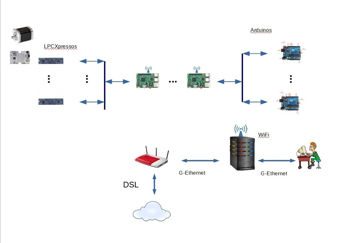
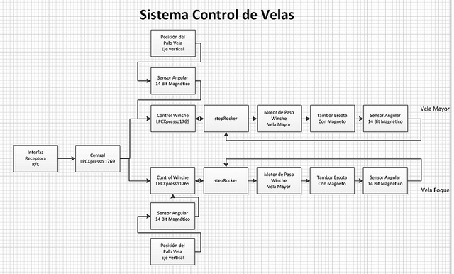
Sorry for not having updated my threads in this forum. Just last week I had me third stroke, fortunately it did not cause any permanent problems besides blocking a second arteria that feeds my brain. Both arterias fortunately hat second ones that could take over the job of feeding the cells in my brain! Pictures taken from my brain have shown that my intense efforts to continue my studies and learning have created and strengthened alternative routes to feed my brain. The stuff I am studying, the experiments I start to do once I have solved the vulnerability issues that rendered my PC inoperable, Windows 7 Ultimate 64 bits with all protection software in place and all updated on a daily basis if required, Allow me to take the short path. Learning, studying and implementing the technologies that are rapidly being developed requires to develop my own scheme to merge them into creating a safe environment for my lab and for the future use of my electronics in the model of the sailboat Carina on the lakes! The picture shows the structure of the electronics in my workshop! It shows me sitting on my PC and being in touch with the Internet via the Modem. By the same means I do access RaspBerry Pi boards which the control the dedicated boards, being the either Arduino kind, supplier specific boards that cannot run Linux like the LPCXpresso ones and/or dedicated control boards for controlling stepper motors or magnetic angle sensors. With devices connected with the Internet are growing in numbers due to what is called IoT, IIoT or Industry 4.0 and the ever stronger hacker activities in the Internet, technologies to reduce the vulnerability of devices connected to the Internet are explosively being developed. Understanding those technologies enough to develop a picture about how to use the to the benefit of securing not just my workshop, but also the electronics in my modelboat is a pretty challenging job, as this is currently taking place in the involved industry! I will go into more detail once I feel better!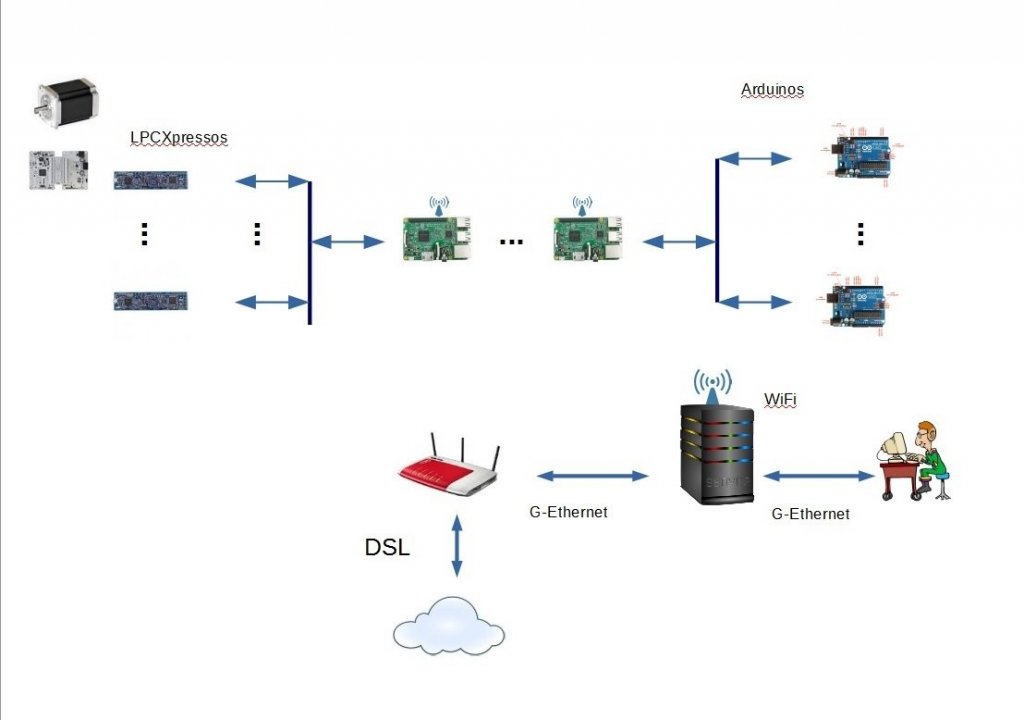
-
Thx! I will probably never get well again. I had to decide I will never again be able to fly to Bogotá, Colombia, where I did live before relocating to Germany in 1976. But I do not complain and i am happy that my curiosity and fascination for our hobby in general and the way I am working on my project is more pushing me to overcome limitations that my health is imposing! I kind of do get angry with myself when I am not able to concentrate enough to continue one of the many streams of work I am pursuing. Also I am more then just lucky to have a wonderful family, a loving and supporting wife, 2 girls, 25 and 27 years of age and my boy with 23. But my activities to take benefit from the technological revolution taking place this days for my model are my biggest motivators. I am still working to improve and organize my workshop. I do plan to share my work on it with you.
-
Hi friends. Since the last time I have published something about my project a lot has happened. The biggest factor slowing down the progression of my project has been my health, followed by topics, fascinating for me, that have opened to my eyes new fields to pursue as part of my project! 2 strokes, 1 thrombosis, responsible for making my second stroke less strong, a couple of times my heart stopped beating due to side effects of my medicine for lowering my blood pressure. Due to the thrombosis that took place due to the cables inserted in my veins that connect my pacemaker with my heart, I had to take a special medicine to eliminate the thrombosis and this accidentally also helped to delude my cerebral infarct. Really the biggest effect on my daily life and capabilities to allow me to work and study for my sailboat project was one of the times my heart stopped beating. It caused damage in my brain. My studies on the other hand help to execute my muscle between my 2 ears helping is to reorganize itself to overcome the impact of the damages. Since my heart events I have never again be fully operational! This is not to have you feeling compassion for me, this is to share that the fascination of our hobby helps to combat the problems due to health issues to those that might share health problems with me! As I started to report in my other thread about modelling my sheet control system, my focus moved from hardware oriented work to such of software and electronics, as well as skills development and improvements on science areas related. The so called MOOC courses, free online courses offered by the best universities in the world through sites like "Coursera", "edx" and so on I have been refreshing my knowledge in mathematics, physics, electronics and IT. The starting point was my activities towards gaining the ability to model by sheet control system. When you model some system you need to verify the quality of the model by comparing the results of using the models with the real world. I decided to use RaspBerry Pi´s, as this electronic board is being supported by the software from "Wolfram Software", Mathematica and SystemModeler. So I did start by making me familiar with the Raspis, to learn how to control them from my desktop PC. A RaspBerry Pi with a WLAN module, all very inexpensive, Raspi 3B even has Bluetooth and WLAN integrated, make it possible to access the Raspi via my local WLAN and even via the Internet. Using the proper means you can control your Rasp board from your PCs desktop, keyboard and mouse, as if those would be directly connected to the Raspi and have its desktop displayed in a window on your PC desktop! I got fascinated, that using a Raspi in a naval model you could communicate with it via wireless, be it WLAN, Bluetooth or cellular. Linked to this was that I did find a provider, that offered cellular phone service at 1 Euro per month and 1 additional Euro per month for 100 MBytes of data. You could even book more data volume for single days. This way my model sailboat in my workshop could be controlled for free using my in house WLAN and up to 100 MBytes per moth if on a place without WLAN availability! I did even register my then 2 Raspis, each with its own entry on a DNS service that is available for free! But this did kill my setup! I have my PC always up-to-date on os and security software. But via my Raspis outside attackers did render my PC with Windows 7 Ultimate inoperable. All my efforts to repair my PC did fail. So I decided to upgrade it to Windows 10 Pro. That made my PC 100% operable again! But this painful experience that did take about a month to fix did make me decide to learn how to operate my setup as secure as possible! Now the Raspi operates with an Linux os called Raspian. So I started to learn about Linux. But today's technological revolution around the Internet of Thinks, IoT, has had as a side effect intensive developments in the area to protect so called "connected devices" from cyber attacks. Even the different states are starting to implement laws that enforce people developing IoT devices. Recently a US government agency has files a suit against a Taiwanese company for not securing the products against cyber attacks. Just keeping track of the explosion of activities to protect connected devices from cyber attacks is beyond my abilities to learn. So I have limited myself to those developments in the area of ARM based devices, as both my Raspis, as well as the other electronic sub systems use ARM Cortex based devices. A result of this has been my definition of an IT setup in my workshop: Basically the picture shows a user like me, sitting in front of a screen and interacting with the experiment setups via WLAN/LAN/cellular. When you go into the details of Linux and how the communication to local/remote hardware takes place, you find out how to make setups to reduce the risk of being attacked successfully. The potential for attack is expressed as "vulnerability area". A lot is achieved by changing the execution of functions from default to unusual setting and to limit who is authorized to communicate and to limit what an authorized entity is entitled to to the minimum required. But those performing cyber attacks are getting more and more sophisticated. Recently the German defense minister said that one of the mayor areas Germany is extending their spending to a "cyber division" of the German military. So the area of cyber war is an area were heavy investments are made by governments. But also all of the other fields of technology that are required to participate on the global digitalization, not only IoT, but also Industrial IoT, called IIoT , medical, automotive, infrastructure and home automation have to jump onto the Internet. So very deep pockets are involved in developing protection to reduce vulnerability, in developing cyber war methods. Also the research activities in areas related to this cyber war are developing the scientific ground for safer solutions! It is interesting to mention, that no device connected to the Internet can be made 100% secure. all is about making the cost to succeed as high as possible by making the investment of extensive resources necessary! At least until quantum computers become reality, what as a result forces sciences related to cryptology work on finding methods of encrypting that are able to withstand attacks using quantum computers. There is the technique of "virtualization" that is protecting environments in the computer server world. It is said that the methodology of virtualization is one that achieves 100% isolation and as a consequence protecting the environment which uses virtualization from what ever comes from either those virtualized environments of from attacks to such virtual environments. Intel CPU's have support for virtualization build into their hardware and newer CPU's do have more sophisticated support for virtualization. So in the setup for my workshop shown in the graphic above the computer is setup so to benefit from virtualization! This methodology is available since a long time and can be seen as mature. The challenge is to make it possible to use this methodology in deeply embedded systems. We as naval model aficionados just call it "electronics" and mean simple boards using a micro controller, ARDUINO is well known as is RaspBerry Pi. This small graphic presents the 2 types of so called "Hypervisor" that make the virtualization available in Systems. The "Hypervisor Type 2" is an application that runs on an os like Linux, Windows Server or Desktop. Here the hardware of the system is controlled by the os as we know it from our desktop PC's and on it is running an application called "Hypervisor", "VirtualBox" being an example of the many products available. The hypervisor type 2 the opens guest applications with their own operating system. The os in this environments believe they are the only software running on the hardware so that unmodified operating systems and application can be executed. No event taking place within this environments can access the hardware directly. The hypervisor intercepts them and returns to them as if they were doing it on their own. This makes it possible to run i.e. Linux Ubuntu on a PC with Windows Desktop. The draw back of this is that it requires extensive resources, as it has to duplicate a complete OS for each virtual environment! Also an important draw back is, that it is impossible to achieve predictable real time responses. Known should be this setup for anyone who rents a server from a provider. He does not get his own physical server but just a virtual copy of it! This virtualization ensures 100% isolation between the virtual environments and its applications. On a board with a controller on it we have to basic versions. Arduino is one, where the programs we write ´for it are executed directly of the hardware, it is called "bare metal" . Arduino have very little flash memory and even far less RAM. So here a hipervisor type 2 is basically impossible to use! The issue is different for boards of the type of RaspBerry Pi's. They have still limited hardware resources compared with Desktop PC's and Servers, but enough to allow a Linux and its application to be executed on them. So hypervisor Type 2 are possible for them and as long as our application can live with those limited resources, all is OK. But still real time is only possible to implement in a very relaxed way! So lets look into Hypervisor Type 1. This software is executed as we introduced the term earlier here, running a a bare metal software. On a hardware of the kind like the RaspBerry's hypervisors Type 1 are meaningful and due to the fact that the vulnerability issue is getting a mayor aspect you can find ports of Hypervisors type 1 of the Raspi's. What remains affecting such systems is their hunger for resources, but using a hypervisor type 1 or 2 on a Raspi is possible. This picture shows what is demanded for any comercial application that has access to the Internet. The topic of security and vulnerability start from the very beginning in the Design phase and goes to its desposal or destruction. Like it is happening with the drones for our aviation model makers, law will enforce more and more rules to be able to fly drones and at one time this might extent to naval modeling R/C. I am a believer that providers have to develop setups that hide the complexities of reducing vulnerability, for commercial developers and even more for hobbyists! A first result of my reseach work to the topics listed so far is my need to develop a workflow which uses a development setup on my PC that makes the development work to take place in a virtual environment. Further it requires me to understand how to develop from such a virtual environment for my RaspBerry Pi boards, for my Arduinos, for my other ARM based boards. This requires to fully understand and execute my development work in this way. There are ways to do it, but I need to start experimenting with it. Here my health problems are blocking me to develop a clear picture of how to do it and to start doing it. I will need to setup a checklist that achieves a safe and effective setup. I do my software development using the programming language "Python" and the development environment, short IDE, PyCharm from Jetbrains. But, typical to the speed technologies are evolvong, there is a second technology besides "Virtualization" called "Containerization"! Here the graph comparing both technologies: The graphic of this compare of the 2 technologies make evident why "containers" are better suited for embedded systems! At he initial phase boards of the kind as RaspBerry Pis are more adequate that those like Arduinos. The dominant but not only tool for this technology is called "Docker" and is available for free, You can also see that Docker takes the place a "Hypervisor Type 2" takes in a virtualization setup. But you can also see that Docker based applications do not require their own copy of an operating system, but just those services that are specifically required to execute a certain application. While virtualization offers 100% isolation and so reduces the vulnerability of virtual environments and the host os, the isolation in a container environment is more equivalent to how multiple applications that run on a desktop OS like Windows. We know that if one application crashes there is a fairly high probability that the whole system crahes or at least gets damaged! So the next step of the research taking place this days is to develop a hybrid solution that combines the advantages of both methods while reducing as much as possible their disadvantages. To better understand the line along which such a "hybrid solution" is probably to be found it is helpful to know the concept of "micro services"! Micro services are a method to implement software applications by dividing it into sub functions are the so called micro services"! An application so becomes a bunch of micro services interacting to deliver the functionality of the application. The benefit of such a way to program applications results from the encapsulation of software functions. Each such software function is implemented in such a way that it interacts with other micro services via a common means of doing so, so that errors cannot propagate. This makes it dramatically simpler to ensure a certain functionality is bug free and implemented in such a way it is reusable to the maximum extent possible. Corporates can that have those micro services be distributed in their corporate environment in a way to ensure best load over the resources of a corporate. So if we envision containers to implement such a "micro services" kind of functionality this would benefit that it could be executes were ever a container environment is available because each container includes all it requires to execute the code within it. So containers are used "orchestrating" them to implement a functionality desired. Each of the containers allows to define what other containers are allowed to interact, how they interact and to what each of this interaction is entitled to. So while I am still working on getting a more complete understanding of Docker and its set of tools to be able to add from those understandings were and how I can define who is entitled to what! My objective as of today is to do all development work from a virtualized environment to reduce as much as possible the so called areas of vulnerability on my PC and on my RaspBerry Pi. Only when i have such a check list I will start to do my experiments required to verify models of my sheet control system for my sailboat model "Carina" and to use the same scheme to have the electronics in my sailboat communicate as well as my sailboat to communicate with my radio control for the sail boat!
-
Design by Modelling
Hellmut1956 replied to Hellmut1956's topic in CAD and 3D Modelling/Drafting Plans with Software
Thanks for both of your replies! @mtaylor: I am dealing with defeating the erosion of my math knowledge over the last 4 decades since about a year. I had to start working on it as it became apparent to me that without a certain level of mathematical skills it would be impossible to accomplish my goals! But what is key to say is that there are wonderful resources available online and for free to work on the mathematics and if you keep in mind and pursue the intention to apply it to naval modeling issues they are neither boring, or tough or dry to deal with, but a key to get access to a whole world of new possibilities. Here the link to a course offered for free from the MIT in Boston by its "OpenCourseWare" program. The book can be downloaded for free and legal as a pdf archive at the homepage of professor Gilbert Strang! Once you overcome a certain degree of intimidation, is really just in the mind and not real, you start to realize that this whole course of calculus for single variable equations is just the presentation of diverse techniques used to solve the creation of derivatives and integrations! I have had access to a book about analysis and one of linear algebra for dummies from our local library and there were tables that put all those schemes in tables. But what helps a lot more is when solving in parallel the work assignments from the course and the book by learning how to apply the software "Mathematica" from Wolfram Software! A Home edition license is really not too expensive. The key benefit of doing this is, that as we plan to use the mathematics for our naval modeling hobby and not to become mathematicians, through the course you learn to interpret the results from mathematical solutions, but have the software tool Mathematica do apply the mathematics required! -
Design by Modelling
Hellmut1956 replied to Hellmut1956's topic in CAD and 3D Modelling/Drafting Plans with Software
The sheave shown in the 2 images is many, many years old and I did make it using my own lathe. So any changes required or any new design for sheaves will not be a problem! @mtaylor, any data would be very much appreciated! I will look into the lateral friction issue, as I have been told that also friction between rope and the lateral walls of the blocks is also something I have to take into account! To look closer to the original the lateral walls of the blocks have to have at least at the surface a wooden lateral wall. @druxey: just imagine the pulley with the boom in an angular position close to 90°! Here not just the friction between the rope and the lateral walls, be it of the sheaves or be it of the blocks, but also with the water. But good think about this pulley touching the water is that that helps the sail to open! In the opposite direction when the winch is pulling I do use a 3 Nm torque stepper motor and can change it to a 8 Nm one, so pulling force from the winch should not be an issue! Just a small remark on my health issues! 3 years ago I had my first stroke and it was located in the brainstem where besides the function of swallowing is located, but also the respiration center. For the first week I had to be fed and received to drink and medicine through a tube, no fun! But if the respiration center would have been affected, well I would be either in hell or heaven! Then I had strong problems with my medication so that I got cardiac rhythm problems that let my heart stop beating a couple of times, the first time unfortunately so long that some grey cells were damaged resulting in a problem of reduced concentration capabilities.. So I got a pacemaker, medication was improved and then I got a thrombosis were the cables from the pacemaker entered the vein and so i got medicine to fight the thrombosis! nobody knows what thinks are good for, because i suffered a second stroke while taking those medicines. The consequence was that while it is surprising I suffered a stroke while taking the medicine to fight the thrombosis this had the effect that the stroke was light and just of short endurance. Then they discovered, I am participating on a long term study made on stroke patients a bigger stuff close to my brain and it had to be removed. Fortunately harmless! So my therapy to fight the damage in my grey cells are the studies I am presenting here. No better therapy to have the brain reorganize itself to fix the damage then exercising the muscle between the 2 ears! . This combined with the fascination of dealing with our wonderful hobby is the source for positive thinking which i have been told also helps! I am not describing my health problems to get compassion, but to show to others that might have the same or other serious health problems that it is never too late and that the forces brought to life by the fun we have for our hobby is a source that helps to face the challenges! But one side effect of this health problems that I have had no event in the last year, is that I am aware of that our lifespan is limited and that I might have not too much time left! So when I took the decision to continue with these activities that possibility that I might not see and reach the result, the time and the activities spend with it are a good choice within the options I have. Luckily I have a wonderful and brave wife and 3 wonderful kids, so that all sides of my life are great. -
Design by Modelling
Hellmut1956 replied to Hellmut1956's topic in CAD and 3D Modelling/Drafting Plans with Software
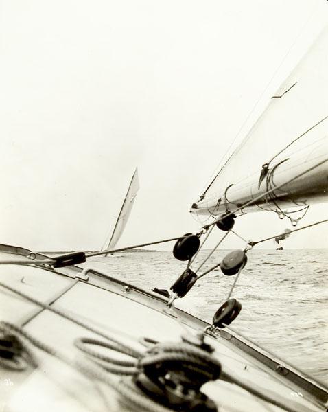
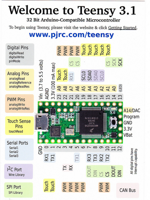
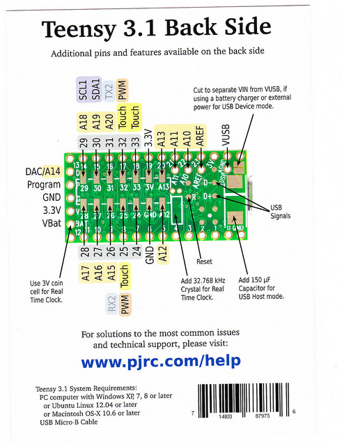
Dear friends and specially those so brave to still read what I write, hallo! In the last months I have received partly very emotional and in times personally aggressive replies to my report on this subject! Such reaction s are expression of underlying reasons that induce people to respond! On one side, and fully understandable, the subject of this subproject of my building from scratch the sailboat model I named Carina, is pretty distant from what naval modelist usually present! On the other side I have gotten such reactions from 2 different communities. One are the naval modelists, and this in all languages I deal with, spanish, english and german, so it is pretty much across cultural borders, the other source is from forum members dealing with physics! The naval modelist and real sailboat skippers argue along the lines that implementing a pulley with seven sheaves as it was used on the original sailboat Endeavour does not work on a model with a scale of 1:20! The basic argument here is, after accepting the fact that my systems concepts has no problems to deal with changing the length of the sheet by up to 8400 mm, that the friction in the sheaves makes the sailboat inoperable due to the friction between the rope and the sheaves in the pulley! The community dealing with physics argues about totally opposing lines of arguments. They say there is only the friction between the sheave and the axis and that by using ball bearing as I plan to do this friction is neglectable! So you can see that depending from the background the experts are coming you get to completely different results about the issue of the friction! I want, nevertheless add, that a real sailboat skipper that has a small pulley on his sailboat wrote that effectively the friction represents a major factor when operating his real sailboat. What he wrote is that the friction between the rope and the lateral walls of the blocks has a major effect! So advancing my studies on "System Physics", the way I want to apply the impact of physical effects in my model and the preliminary results from my investigations on the subject of friction in the sheaves of a pulley. I have felt able to give a call to the physics institute of the highly respected Munich university, Ludwig Maximilian Universität, short LMU. There I was lucky enough to get hold by phone of a scientist willing to respond to my questions. I presented to him the fact that I was planing to study Physics for the Bachelor degree, but that as a person with serious health problems I had to teach the subjects upfront myself, something as will never ever get a job in the industry, gave me the time to do so! I presented to him the two view points I have met and just presented to you, I told him about the limitations of the Euler-Eytelwein-Formula that just represents a formula, not with an "=" sign, but with an unequal symbol =<, that basically says that the real friction impact could be up to the value computed when replacing the unequal sign by an equal sign. I also told him that I had found out so far that even for the classical mechanics in Physics you met very different ways to deal with the same aspects of physics in mechanics giving as an example the classical physics way as reflected i.e. in the Euler-Eytelwein-Formula, but also the views and methods applied by System Physics and by topological manifolds! It became apparent by his reaction that he was willing to take my question seriously and he laughed when I talk about those different ways to deal with mechanics. His explanation about the reactions from the physics community towards the friction in the pulley was due to the fact that many physics view the physical issue from an idealized perspective and that in this view it was correct to say that only the friction of the bearing of the sheaves was present. But that in real world due to diverse reasons even without the rope slipping around a sheave there was a friction component that could be relevant and that the inequality symbol used in the Euler-Eytelwein-Formula was due to those aspects that impacted the exact amount. I informed him further That I had started to study a Master-Thesis hat dealt with the friction between cylindrical bodies and a rope and that did analyze the friction is sailor nodes using the mathematical method of finite elements. For your information dear readers without the intention to lecture those of you that do well know the issue, the finite element mathematical method is a method that computes problems by splitting an object into infinitesimal fractions and integrating the results to get the grand total. So it is what is called a numerical or discrete mathematical method that approximates its results depending onto in to how many sections it splits an object. Simply stating it, it uses the mathematical power of computers to compute a subject split into many, many pieces and adds them to get the final result. Well, this is one of the reasons why i decided to use tools that combine modeling and simulation with strong mathematical capabilities and due to many reasons I believe I have already tried to explain I decided to use the software from Wolfram Software, Mathematica and SystemModeler. So I can start modeling my sheaves and the pulley with seven of those using the modeling and simulation capabilities of Modelica, an essential element of SystemModeler and to use Mathematica to compute, i.e. by the finite element method as applied to the friction between a rope and a cylindrical body, here the sheaves in my pulley, as described in the Master-Thesis I downloaded a copy from. But any modeling and consecutive simulation results depends in a very essential way from the quality of the models used! And exactly here comes into play what i have presented earlier in this thread, the "Hardware-in-the-Loop", short HiL, and "Software-in-the-Loop", short SiL, for which the Teensy 3.1 and the RaspBerry Pi B+ boards have been purchased. I will have to define experiments were I can compare the data resulting from measuring in the experiments and the data generated through simulations using those models! mathematica offers so called "solvers" that can generate equations that follow the experimental data at the minimum error defined and so adapting the models to the real world data. May be, if I do not die earlier due to my health problems this thread and other similar ones in the different forums that I use to get support and feedbacks, I will be able to present the facts resulting from modeling the pulley. I am completely aware and I do accept the following possible results: 1. The experts from the physics forums are right and friction using ball bearing in the sheaves is irrelevant for the operation of my sheet control system in my model scaled 1:20 to the original Endeavour! 2. The experts from the naval communities are right and the pulley is not able to produce results that do not render my sailboat model inoperable due to the friction in the pulley! 3. Any results between those two contradicting positions, or may be even a completely different and unexpected result. But what will definitely be a result if I succeed to accomplish the modeling and simulation of the pulley in my sheet control system, is that i will know and understand the relevant and irrelevant parameters and their impacts! With the following graphic, simple and full of errors, but still the best I have, I will try to present what really understanding the friction in the pulley and the impact of the design parameters have. If you look on this drawing and if you keep in mind that the angle with which the rope embraces a sheave has a major impact on the friction to the movement of the rope around each of the individual 7 sheaves of the pulley, you will see that where you place those blocks containing the sheaves has an important impact on the angle with which the rope embraces a sheave! If the distance horizontally between the sheaves increases, the angle will get smaller. by smartly selecting the diameters of the sheaves this can additionally be influenced. Now you have to be aware of, that the "Momentum" used in System Physics to represent mechanical systems and the pulley is such a mechanical system, requires to analyze and consider independently the momentum in the 3 directions of space, Px, Py and Pz, it becomes apparent that the proper choice of the cartesian coordinate system is relevant. The X-axis of a cartesian coordinate system would be along the center line of the hull, the Y-axis would be parallel to the water surface, horizontal and perpendicular to the center line of the hull and the Z-axis would be vertical. As usual the problems arise when you start to deal with details! Would the position (0, 0, 0) of this cartesian coordinate system be at the floating line level of the hull, means placed at the height of the water surface, would it be better placed at the rotational axis height around which the hull rotates when due to wind pressure in the sail i.e. gets inclined, or would it be better placed at the height of the boom? This is just reflection about where to place the origin of the cartesian coordinate system along the vertical axis! The orientation of the Y-axis is probably less difficult to decide? It should be parallel to the water surface! But where along the X-axis and the Z-axis? Along the Z-axis i have already presented the issues above. Should it be placed where the hull rotates when turning around it, or should it be placed where the rotation axis of the boom of the sail is? But with the Z-axis it is a bit more complicated. The questions as to where it has to be placed along the X-axis raises the same question as to where is the rotation axis when the hull turns left or right? Should the orientation of the mast be the direction, so that any rotation of the boom keeps the Z-axis value of the boom along the length of the boom the same, and so on! The issue to be considered from the mathematical complexities resulting from a bad choice of the reference coordinate system. if an axis of the coordinate system at the same time is the axis around which rotational movements take place, computation is simple, if not, then it is more complex. But besides the complexity of the computations of equal importance is to keep it adequate so that the interpretation of simulation results is kept as simple as possible! So to summarize the issues around the selection of the proper cartesian coordinate system, ignoring that there are also other coordinate systems. Any object could move in 6 ways, called the number of degrees of freedom of the movements! An object can move along any and all of the 3 coordinate axis , the first 3 degrees of freedom of movement, each resulting in its own formula to describe the movement of an object along those axis, a total of 3 of what are called translational movements and as a result translational mechanics. But the same object can also rotate around each of this 3 axis, those are 3 additional degrees of freedom of movement an object has and as a result you can have 3 more formulas or equations that describe the objects rotational movement and as a result we talk about rotational mechanics. The method I plan to use is to have a reference cartesian coordinate system which has its origin at that location in 3D space where the 3 axis around which the sailboat hull can rotate. Additionally I will use auxiliary coordinate systems that are placed in such a way that the mathematical description is kept as simple as possible. So as a result there will be equations that describe how to convert coordinate values from an auxiliary coordinate system to any of the auxiliary ones used This conversion equations between different cartesian coordinate systems are relatively simple, but the key is that the computations taken place in the adequate auxiliary coordinate systems will keep the mathematics as simple as possible and make it much easier to understand the results within those auxiliary coordinate systems. lets take an example of one auxiliary coordinate system assuming the "reference cartesian coordinate system" to be as explained at the beginning of this paragraph! In one such auxiliary coordinate system the X-axis would follow the direction of the boom and the Z-axis the mast! So in the plane defined by those 2 axis is where the sail is located, what ever position the sail and its boom might have in relationship to the hull. So if the sailboat leans to one side by 30°, this would have no effect on the auxiliary cartesian coordinate system. The same applies to the X-axis when the boom rotates. Lets assume the boom rotates to the center line of the hull by 45°. The Y-axis of the auxiliary cartesian coordinate system, being oriented vertically to the plane defined by the X-axis and the Z-axis of the auxiliary coordinate system would follow the rotation of the other 2 axis. So to convert a coordinate value described by the auxiliary cartesian coordinate system to the reference value we would combine by applying the 6 degrees of freedom equations that describe the movements of the auxiliary cartesian coordinate system and so get the values in the reference coordinate siýstem! So what i just described and has to be applied to the 3 momentum equations for translational mechanical movement and to the 3 rotational momentum equations. Now you can see that just by describing the 6 degrees of freedom of an object and having as a result 6 equations is what the Modelica simulation environment has to do with the equations included in a model! So the modelica environment takes advantage of this "knowledge" to generate automatically and invisible to the user i.e. what I just presented to do the computations required to simulate a system using the models that describe this system! Here is where the object oriented implementation of the language Modelica comes into play! When I define a proprietary model of a system or any part of it I start from using object classes given in the "standard object library" of Modelica. So mechanical objects in this library, be they translational or be they rotational have in their classes already included the properties that such mechanical translational or rotational objects have and those are inherited in the new classes that I define using objects from the standard library! So key for any beginner and apprentice like I am is to grasp this concepts and learn to properly apply them when designing our own objects and to use this knowledge when interpreting the results of simulations! Finally I have been told that this weekend i will receive a copy of the brand new version of the Modelica master book, so that I can learn and study it! Let me reemphasize this! I am new into this, I am a beginner and I am an apprentice. So making the assumption I am lecturing you is far away from being so! All I am doing is to share with you, the same way we do it when writing a report from scratch, the up and downs when dealing with the challenges I encounter and as an optimist I am, to may be find some valuable advice from you my dear few readers left! But let me also emphasize it! Even those that get emotional and sometimes offensive as a reaction to my reports. The fact that I have been confronted with such behaviour and attacks from the naval modelist community and from the physics community has been of incredible value to me! The fact that those 2 communities have opposing and conflicting opinions about the friction in a pulley as I am planing to implement in my sailboat model at a 1:20 scale, is in its own right a valuable piece of data for me! Believe me. Just getting to the point were I felt capable to contact a physics scientist at the physics institute at the LMU and ask the question has taken a large effort from my side! To ask the question properly i did face 3 challenges, at least! 1. Understand and put in context the statements received from experts in the naval modeling community. 2. Understand and put in context the statements received from experts in the community pf the physics. 3. To be able to formulate my question such that my counter part at the LMU took my question seriously! 4. To be able to put the former 3 sources in relationship to refine the objectives of my design by modeling. I am certain and not yet even close to be able to grasp the problems I will encounter when dealing with the mathematics in this context! And so I am not even able to say what questions I might have that I will present in the mathematical communities in the proper forums. I know, that the very little I have been improving my studies just to get back and up to speed with the mathematics I once knew when I joint the university and I was an excellent student at school kind of just enabled me to have a framework of understanding of what those mathematical courses that form part of the bachelor of mathematics and of physics are all about. They really are not more than just the basics skills required to get away from beeing a mathematical analphabet. As a result I have an idea about the mathematical methods available and I have the means to know where to look in to acquire the knowledge in the different fields of mathematics as the need pops up! I hope that learning to use the software tool Mathematica will help me to overcome my lack of experience in applying mathematics by understanding enough of the mathematical methods and of the use of the software Mathematica to "use" the mathematics for my goals. I am very explicit! I am in doubt if I ever will have the courage to say about myself to be a mathematician, but I do have the hope to be enabled to apply mathematics as required for reaching my objectives! As we are in a naval modeling website i would like to add 2 pictures from the self made sheaves that I plan to use in the blocks that will make up the pulley in my sailboat: This sheaves I did make using my lathe in aluminium and I have inserted a ball bearing and allow for an axis with 2.5 mm diameter and have an external diameter of 20 mm and an internal diameter for the rope of 12 mm. The height of 4 mm of the shoulders I hope will allow me to prevent the 0.9 mm diameter Aramid rope to get in touch with the wooden case of the block in which the sheave will be installed! -
Design by Modelling
Hellmut1956 replied to Hellmut1956's topic in CAD and 3D Modelling/Drafting Plans with Software
I will respond once I have had a progress! -
Design by Modelling
Hellmut1956 replied to Hellmut1956's topic in CAD and 3D Modelling/Drafting Plans with Software
Hi druxey, not every one is so knowledgeable as you are. but may be you can then help me with my road blocker! According to system physics, a way to deal with physics based on the methodology of the method originated with complex dynamic systems, mechanics are described around "Momentum" being the content of a recipient, and momentum flow, force, being what is following into and out of the recipient. I am stuck as I do not find how to model an individual sheave embraced by a rope with a certain angle. i do have the Euler-Eytelwein-Formula in mind to be used as equation in the recipient. If you look that "draft" of a flow chart describing a single sheave I have made using Berkeley Madonna, I do not know how to reflect the "Momentum" within the recipient that represents the sheave! The forces are pretty clear, so the pull tension applied to the rope would be varied in a simulation from a value of "0" to some higher value. Based on this the Euler-Eytelwein-Formula would give me the friction that works against the pull tension. So at some point there will be an equilibrium condition between the pull force on the rope and the friction and as a result the third arrow would have a value of "0". But what is the mass in the equations for momentum and the pulling force according to the system physics? I have been collecting material to study this aspects of system physics. As soon as I am enough through to either know the response, in which case I will publish it, or know that I am not able to find a response, then I will contact Professor Maurer and publish his feedback! If you are able to help me I would be very thankful, as I am keen to do my first simulation just around the behaviour with a single sheave! -
Design by Modelling
Hellmut1956 replied to Hellmut1956's topic in CAD and 3D Modelling/Drafting Plans with Software
Hi to those that still read the thread! i want to go into the details of presenting the 3 pillars upon which I base my efforts to model the pulley that is part of the sheet control system as shown in my picture from the original Endeavour and which was the first picture presented on my post dated April 7th. I have decided to keep it as simple as I can. This means that it is very probable that I will miss some aspects which make it either impossible or difficult to follow. I will do my best to prevent this, but I want to let you know that I have interesting links to more solid data. 1. Complex dynamic systems: This science was initially developed by the "Sloan Institute" at the MIT in Boston starting 1956 in the financial domain. I want to give you the link to this page, where I would say the information presented is what I would consider the fundamental. Right, that this picture is intimidating and pretty sure not understandable by a normal reader. But you would agree with me, that what the author is trying to model is a really complex system which requires a method to grasp all the interdependencies in an incremental way to be able to really have the model reflect this complex system! When you look back onto what I have presented over the comparatively simply aspect of the control of the sheet when the sail wants to open more and my sheet control system has to manage to deliver the sheet length required for the boom of the sail to do so, you would agree that what I presented there in my first post in this thread is a complex system and that it has many aspects influencing and interacting. What soon became evident to me was that I need to have a method applied to no just consider those relations I had identified by reflecting over the subject, but a method that would make it possible to model that system and in this way capture all aspects that will end up being relevant. I have assumed I had not grasped all! To present what is the essence of what complex system dynamics has to offer to me to model my sheet control system and in the first step to model the pulley, I believe can be achieved by taking my current status of the flow chart I am developing to model my sheet control system in the same way this overly complex flow chart above does. I do use a tool that is available for free in a demo version that has just the limitation not to allow to save the work, "Berkeley Madonna". I have purchased a license of this tool. I believe the beauty of the graphics in its flow chart is supporting to grasp the content of a flow chart and besides this, my source for learning the other 2 pillars upon which i base my modeling effort uses this tool in its videos in Youtube! The flow chart contains 3 building blocks, of which 2 are already available in my most simple initial flow chart. The recipient and the flows! The recipient is there to catch magnitudes that are accountable, means where you can add and subtract what inflows contribute and what outflows take from it. So when you look in the over complex mature flow chart shown initially, you can see those recipients as square boxes and the flows as arrows consisting of 2 parallel lines. The 3rd. element are those circles or globes. In the recipient you have equations that contain parameters that describe mathematically how the magnitude changes do take place. The globes to visually show in the flow chart from which are part of the system those parameters are coming from and contain the formulas to compute the values of the parameters in those equations in the recipients. The flow chart tool shows question marks when parameters are still undefinable by the available relations reflected by the globes and their associated ingle line arrows. As a consequence the flow chart makes the complex task manageable by allowing to depict dependencies and by supporting to have those dependencies and the related equations consistent and complete. In my own simple initial chart I am expressing a single sheaves of the 7 in the pulley shown in the picture from the Endeavour which are in a total of 6 blocks. So once I have completed the model of a single sheaves to reflect how the friction in a single sheaves relates to the tension of the sheet, of the angle it is embracing the sheaves and some other aspects, I can then use 7 instances of the model of this single sheaves to model the pulley as a whole! I hope this helps you to explain why the complex dynamic systems science contributes an important element to my objectives. 2. Second Pillar, the equation based object-oriented modeling language and simulation environment given by "Modelica". The modelling language Modelica basically uses the methodology developed and constantly being improved by the science of complex system dynamics of the recipients and the flows. This is tremendously important and is probably one of the reasons why Modelica is used extensively in the industry of auto makers and plane makers, probably the most important software player for such tools being "Dymola" from "Dassault"! This is the graphical representation of what in Modelica terms is being called the model of a component. As it can be seen on the graphics, you have the symbol of a spring, you have 2 connectors and you have a large grey arrow that reflects a direction that in this context has no ther meaning than to define what is a "positive" direction, so parameters effective in this direction have "+" sign, and what is the opposite direction and has a "-" sign. What it does not impose is the direction of what are "inputs" and what are "outputs". This is one of the tremendous impacts of the fact that Modelica can use what is caused "acausal" models, opposed to what "Matlab" only supports and it is "causal" objects! Now I can imagine that this terms used in the previous sentence can be and probably is intimidating at the first glance. But I assure you it is simple and clear. Her just the textual version of the spring model: As you can see, under the title "equation" all that sows up is the normal spring equation. The red colored text gives a reference that the objects used in the model do inherit properties by showing the class hierarchy of the used components in the circuit, here the simple case of a spring. The challenge that makes this kind of modeling language possible is that the software by its own has to generate the equations to calculate the unknowns. Tools like mathematica from Wolfram reflect the tremendous advances that have taken place in developing mathematical "solvers". This actually makes it possible to have the software tools apply themselves the mathematics required to solve mathematical problems, here calculating the unknowns depending of the "direction" which the model is used. It is a bit like when I was in high school and the electronic calculators did enter school. Did we get points in the past by calculating the solution, now with electronic calculators the points were only given by expressing and defining the equations into which the numbers were entered and calculated using the electronic calculator! same is possible now! The tool, the Modelica development environment, applies the mathematics to the equation to solve the job by applying mathematics! So the challenge for a naval modeler could be seen not in developing the skills to apply mathematics, but to apply his or her understanding to formulate the equations and understand how to formulate mathematically the relations between the elements of a system! The simulation environment of Modelica then applies the mathematics. Causal objects are causal in the sense that inputs are clearly defined as causes that happen, that then are processed according to some rules and as a consequence generate "outputs"! Simple familiar cause and result, a concept we are all familiar with! So acausal components state in their name that this fixed direction from an input being processed to generate an output based on those inputs does not apply the same way! Acausal components have, as shown in the graphics of a simple model of a spring, and equation in the model and that equations are being supplied with the required parameters from the "connectors". The consequence is, that the same unmodified acausal model can be used when inputs are those entering the model from the left and generate the outputs that are displayed on the right, as any causal object does. But that same unmodified component can receive inputs from the right side and generate outputs on the left side. Lets take a very simple example we naval modelists are all familiar with: Lets take the simple model of a DC motor: This simple graphics shows how a model of a system looks like, to which you apply a voltage. The resistor and the inductance shown in the graphics are used to model the electrical behaviour of the DC motor resulting on the right side in a rotational speed of the rotor in the DC motor and a torque available. Here the relatively complex modeling of the above circuit using Matlab, respectively generating a causal model. Now if I take the original Modelica modeling of a DC Motor and instead of applying a voltage, I do put a scope that shows the tension over those same poles. If I now apply a torque to the same model above, that the scope will show the voltage generator by the DC motor now operating as a generator. As you can well imagine if you would have to model this were the DC Motor becomes a generator would require a complete redesign from scratch using causal objet methodology. Murphy was active, I could not find the graphic showing the inverse use! What Modelica environment does depending on how models are connected using the "connector elements" called "flange" in the symbol for a spring above, is to generate equations to have the same number of equations as there are unknowns! I. e. it applies what is known analogously in analog electronics, the "Kirchhoff Laws"! This is called the voltage law from Kirchhoff and it states the obvious, that in any circuit the sum of the tensions = 0. This analogy in complex dynamic circuits diagrams and in Modelica represent the content of the recipients. This is the current law. it states equally obvious, that the sum of the currents at any node = 0. using such principles, on which I will elaborate in the next pillar description about System Physics are examples about how the Modelica simulation environment generates equations so to be able to solve the equation within, transformed to the actual direction of input to output, to compute the unknowns! 3. Pillar, System Physics: System Physics is a new method to view physics and that takes advantage of the methodologies of the other 2 pillars I have presented so far. I will introduce you to it in my next post. It will show how all 3 pillars together make a modeling possible and not intimidating, if you are introduced to the simplified perspective that I am working to develop and simply start to use the powerful software tools available, a lot of them for free. -
Design by Modelling
Hellmut1956 replied to Hellmut1956's topic in CAD and 3D Modelling/Drafting Plans with Software
@druxey: You are qualified! When I admire the craftsmanship work in other fields of our hobby, then what I am doing is not more then just apprenticeship. What I am frequently encountering is that be it electronics, or be it like in this case a combination of electronics and virtual technologies, the inexperienced naval modelist is being intimidated by the subject! If you the naval modelist builds radio controlled models, electronics has plenty to offer. A decade ago a friend and myself decided to publish a tutorial to build an experimental board just to learn hands on that 90% of the application of self build electronics can be achieved by learning some simple steps and so get a set of "lego" stones, which combined allow to build stuff that can enhance radio control models. As to the technique of design by modeling! I am close to a decade and a half active in my hobby sine it became evident I would not be hired anymore. If after such a long time dealing with our hobby with the goals I have presented I would still be dealing with trivials, then my focus would not be in advancing in my fields of interest. by the way, always moving into new fields by definition I am always an apprentice and as such prone to mistakes! You my dear druxey are more then just welcome to ask any question that you might have. You would be doing me a great favour, as answering questions has to my experience a huge impact on my own learning curve! -
Design by Modelling
Hellmut1956 replied to Hellmut1956's topic in CAD and 3D Modelling/Drafting Plans with Software
Hi friends, since my last post I have been having interesting developments, not at least also thanks to critical questions being asked or statements about either why I was not just building what I plan of the statement that what I was planing to build to control the sheet in my model sailboat Carina would not word due i.e. the friction in the pulley between the 7 sheaves which it contains and the rope of the sheet! Sadly some even felt that they had to get angry about my stubbornness and may be seeing in my unwillingness to accept their expert opinion as not accepting their expertise! First, I believe we naval modelers are stubborn as otherwise we would not have the perseverance to work on a single project for such long time. Second it was my goal from day 1 to see the activities I engage in the context of building the model as the real objective. I have been engaged in learning a bit about using my lathe and my milling machine, I got into electronics i have been working on developing my workshop in parallel to the activities on my model. Now after nearly a decade working on the project it is not surprising that i am engaging into technical aspects pretty advanced! On the other side as I do enter into projects of the most diverse kind I am by definition always an apprentice in what I am doing! I do write about what i am doing to share my experiences, to may be motivate one or the other to follow on some of the aspects of the project and by explaining and responding my understanding of the subjects improve! So, as there is no obligation to read any post and as I make clear how my projects relate to the topic in this forum, naval modeling, I hope it is fine for everybody that I do what I do! Lets go into the activities and achievements since the last post and into what I am working right now in the context of this thread! may be some of the information has been written about already at another place of the thread, but I do so to put thinks in context! Due to my objective to understand and hopefully verify my concept of a sheet control system able to change the length of the sheet by 8400 mm in a hull just 1650 mm. Over all that I have started to present above an in depth understanding of the impact of any parameter existing in the way the concept is implemented. There are the following goals: 1. Achieving the most energy efficient implementation possible. Remember this model is sourced by batteries and the 2 large stepper motors can consume a lot of energy! So an energy efficient implementation makes it possible to use a much smaller battery capacity. The 12 LiFePO4 cells, each with 16Ah capacity was the biggest capacity available at the time I made the decision to ensure the model would not have to be recharged during a single day at the pond site! 2. Verifying that my concept of a sheet control system achieves not only the desired functional operation, but also to be reliable. 3. To identify what wind speed minimum was required to generate the pull force on the sheet to open the sail, something experts consider a fatal problem of my concept to implement the pulley as used in the original sailboat Endeavour: 4. Find which physical dimensions and position of the 6 blocks and 7 sheaves result in a good visual implementation as the one on the original sailboat and what the many parameters affect the wind speed required to open the sail against the friction in the pulley! So with such objectives as I wrote I learned about the methodology of the "Design by Modeling" and as a result I am convinced that this methodology makes it possible to have the greatest chance to achieve my objectives! When I learned about the existence of this methodology I learned this in the context of using either "Matlab/Simulink" with several toolboxes from MathWorks or Maple/Maplesim from Maplesoft. Both sources had one big problem for me. They had no licenses offered for home users and so the cost of the license was prohibitively expensive! Now I am such a fool, but I only use legal software, so cracked version were a no way! But I learned that for students the access to special student or academic versions was possible, but only usable while registered at a university! Now the other aspect I found out soon was, that for what ever tool I was going to decide myself to go with my nearly 4 decades old mathematical skills had eroded and that the development of the PC and its performance had between other reasons led to an impressive development in the field of mathematics. Even more, no university course relevant to my interests was possible to be studied without getting deep into mathematics! Now, as I have suffered 2 strokes, multiple times I heart stopped beating due to problems with my medicamentation that resulted in cardiac rhythm problems I got a pacemaker and as a consequence of it a heavy thrombosis in my right shoulder. But worse was that those times my heart stopped beating some of my grey cells had suffered due to luck of oxygen, what results in a degradation of my concentration endurance! The nice side effects of this were one one side that I got very aware of that my lifespan is limited and that as a consequence I might never finish my projects, the other side is that by doing the research work, the studies I have to do in the context of my design by modeling project those activities are actually a therapy to help my brain to reorganize and fix what got damaged! I am writing this not searching for compassion, but to give you some background of myself and this project! Now as a consequence of the prohibitive cost of the software tools from the 2 companies mentioned above I started to look in the offering from Wolfram, Mathematica and SystemModeler. Let me just summarize by telling you that during my visit to the Embedded World 2015 trade show in Nürnberg I learned that MathWorks actually now has an inexpensive license in its offering, even cheaper than the home license offered by Wolfram! Still so I have decided to go with the offering from Wolfram. To explain why i want to start showing the environments in which the design by modeling work takes place: This to images are meant to represent the 2 complementary environments. The PC on the left is the virtual environment in which design, modeling, simulation and verification takes place. On the right the PCB i use to control a stepper motor is representation of the physical real electronics which execute software and in this combination represent what one day will be build into the sailboat model. To just give you a glance of the complexity next a diagram I made to explain the constitutive elements planned to be used to implement my sheet control system: I will not get into details right now as a lot has been already been done earlier in this thread. But this diagram, were the PCB shown above is just one of two "stepRocker" PCB used in the system to control the 2 stepper motors, one for the main sail, the other one for the Foque sail! Let me indicate that modeling something is fine, but that the quality of the simulation results using such model has to match what is measured physically in the real embedded world! This step is named verification and it demands to define experiments to verify the different parts of the model being developed! As of about a month or 2 ago I felt that my studies to refresh my mathematical skills, while far behind what I had hoped to accomplish after one year of studies and the purchase of the tools required I feld I could start modeling and did choose a subsystem that while being comparatively simple it addressed the important question about what a wind speed would generate the pulling force in the rope enough to equal the friction! The reasons were that I felt enough development in my mathematical skills not to be intimidated by the mathematical notation so that I could grasp the properties of equations enough to identify what those equations meant for my objective of modeling. But also because I finally had identified 3 pillars based upon which I could pursue my objective of modeling: The 3 pillars: 1. Methodology developed at the MIT in Boston starting 1956 in the field of the science of complex dynamic systems. 2. The modeling language Modelica, an object-oriented equation based modeling language and simulation environment which is being supported by SystemModeler from Wolfram. 3. System Physics: An innovative perspective on physics that applies the methodology coming from the science of complex dynamic systems and allows the modeling of the physical concepts in Modelica. Finally Wolfram offering both the software Mathematica, probably one of the most powerful and universal mathematics tools in the market in combination with SystemModeler and the modeling language Modelica offered a powerful but affordable environment to model in the first part the pulley. But also the software Mathematica has been made available for free with the RaspBerry Pi running on it. This way the software Mathematica delivers multiple services key for the virtual environment, i.e. setting the parameters in a model according to mathematica equations so that multiple runs of the simulation could be done with the parameters under the control of the Mathematica functionality. But also in combination with the RaspBerry Pi i could start learning and experimenting how to best combine the virtual environment running on my PC with the physical environment and so learn what experiments run on the physical embedded hardware could be verified with the simulations running on the PC in the virtual environment. But additionally for the SystemModeler there do exist the means and the tutorials to interact between the modeling and simulation environment from Wolfram with an ARM Cortex M4 board, the Teensy 3.1 with a supported protocol called Firmata: Fortunately I am about to have my electronic lab ready for the purpose of studying the interaction of the 2 boards with the respective Wolfram software. Goal is to enable the boards planned for my sheet control system to be able to interact with the Wolfram software at least at the same extend as the 2 boards can actually do! Well, enough for this post, as i am noticing that I am starting to get tired!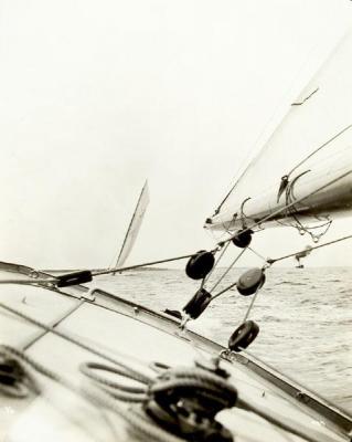


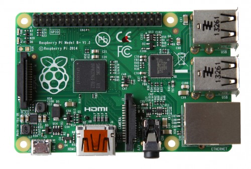
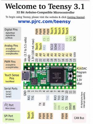
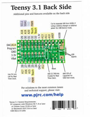
-
Design by Modelling
Hellmut1956 replied to Hellmut1956's topic in CAD and 3D Modelling/Drafting Plans with Software
Hi mtaylor. Thanks for your response! You are absolutely right, that the topics presented are very technical! I was surprised to find out during my visit to the trade show "electronica" in Munich, probably the biggest trade show for electronics worldwide, how little knowledge about this technology was in the minds of the really technical people I talked to during the show. Only very few knew details about simulation tools like those as Maple, Matlab or Mathematica in the context of simulation and none the difference to "standard tools" like Spice and similar. I was asked the smart question what was what this technique had to offer additionally to tools like "Spice" and in what way it goes beyond what Matlab, Maple or Mathematica have always offered. My response was, that as an extension to the functionality of tools like Maple, Matlab and Mathematica the simulation tools from those companies in combination with the functionality best described by referecing to the tools available under openmodelica.org and the description of models not only in "causal", but also in "acausal" objects made those tools powerful and heavily reusable and that while this led to speeding up the process of design it allowed for optimizations at a new level of detail in multidomain environments. Multidomain meaning in systems that combine not just electrical systems, but i.e. mechanical, rotational, and so on, just connected by "connectors", a key concept well introduced either in the documentation found at openmodelica.org or at Maple in the introduction to maplesim in their website. I am aware, the more I dig into advanced and specialized topics, the less I will find reader willing to follow! But our hobby offers opportunities far beyond the usual scope and I am confident that future aficionados more familiar with those topics will one day embrace them. But it is also so, that digging into new areas requires much more extensive studies before elegant and easily applicable working schemes can be found and communicated. I hope that some of the contacts I am making on trade shows will lead to generate a community willing and able to pursue such goals. When starting to promote the use of electronics as a technology for our hobby I was lucky to find some supporters and I found that modelists in the plane building domain are more open to this new technologies, as the FPV, first person view, activities demonstrate. I know naval modelists tent to be more conservative and in avergae have a couple of additional years on their shoulder. I have written about my health problems and their impact on this activities not to get compassion, but to present that the mental activity in such an area requiring extensive studies can combine a lot fun with the support of helping our brains to repair eventual damage by reorganizing itself. Working with the brain is like exercising physically, both develop the muscles involved. in case of the studies, our brains! -
Design by Modelling
Hellmut1956 replied to Hellmut1956's topic in CAD and 3D Modelling/Drafting Plans with Software
Last week we had a very important trade show here in Munich called "Electronica" which I did visit on Thursday. I used this opportunity to investigate how familiar companies present there were with the concept of "Design by Modelling" and found to my surprise that the knowledge between those present at the booths at the trade show and no idea of it. I then used the strategy to mention a commercial player in this area, mathworks and their products Matlab and Simulink and so at least found a couple of persons that had heard about this product, but only as a tool to use their "Solvers", software tools that help to solve equations as part of the simulation and the mathematical description. Those individuals I did ask if they knew about the language "Modelica" and in this context about causal and acausal model elements. Surprisingly not a single one hat a clue abut it. The best question I was asked was about why design by modelling was different from using tools like Spice, an industry standard tool for modelling electronic components, specially under the perspective of analog behaviour. My response was, that design by modelling and a core tool in this context the language "Modelica" allowed to combine multiple domains into a simulation the way they were used to use Spice. To you my appreciated reader, with domains in this context we are talking about fields like electronics, mechanics, hydraulic and stuff like this that normally are perceived as different fields developed independently, but combined in embedded systems. Embedded systems in our hobby the naval modelism means embedding electronics in an application opposed to have an external computer involved. I am writing you this, because it reflects that the use of system modelling is something new in the university environment and from where a new generation of engineers will start to have this move to a widespread use in the industry and that so our hobby is in touch and opens itself for the latest technologies! But why is this of interest to us in our hobby, orr may be better asked, what benefit can this have for us as naval modellists? Well, as I have expressed in the past, naval modelling is a hobby that combines a rich portfolio of technologies, like working with wood, with metal, with plastics, which put us in touch with a rich portfolio of tools required for those materials like glueing, milling, lathing, laminating, 3D printing and many other craftsmanships. But since some time the some of us not only use electronics from vendors, but also see electronics a an open box to make wonders happen. Well, technically speaking, we are used to move in diverse domains and to see their behaviour in the physical reality of this world. The technology of system modelling in general and the language "Modelica", which can be downloaded for free from openmodelica.org alow to combine those diverse technologies, here named domains, into a single "modell" of a system that we might like to design as part of our projects in making a model. Having written this generically to supply to you some background information I am working to use this system modelling technique to model my sheet control system, to analyze and verify its ability to do what I expect and to be able to optimize it for energy efficiency, something important when we keep in mind that our models all are battery driven. Some of you may say, why should I bother about this, and right you are! Why should a fan of plastic models bother about carton models, why should a fan of regatta competition with sail boats bother about static models, and so on! My answer is that every aficionado of our hobby doesn't have to bother about techniques in our hobby if those do not contribute to his goals and objectives. But it is the wealth of our hobby that it spans a wide field of technologies and abilities and so it offers each of us a playground to pursue its own wishes. The use of electronics and now the use of system modelling shows and to my believe proves, that our hobby really is not something just for those of us that have collected a number of years in their lifespan, but that it really makes it possible to melt 21st century technology into our hobby. So I want to end this contribution today by presenting what the concepts of causal and acausal systems mean! Here a link to an introduction which I will try to explain less rigorous and hopefully easy to understand! Imagine a simple circuit to feed a DC motor. On one side you have a power source, in our models i.e. a battery. This battery allows to apply a voltage to the DC motor and so a current flows through the DC motor making it turn. here we are combining an electrical domain, the electrical circuit connecting the DC motor to the battery and a physical domain, the DC motor creating a rotation movement and a torque that can i.e. move a bota by having a propeller turn. If we add into this picture the well known fact that a motor generates heat, we know if we apply a voltage to a DC motor that is above the specified value, too much current flows through the DC motor and it will get warm and eventually burn out. This would be another domain, the one of heat flow! if we model such a system in a causal way, the traditional way, we have a sequence of events which start at the battery and its supply of voltage and current and the DC motor creating rotational movement and heat. But what happens if now I do disconnect the battery from the circuit? well the motor sops rotating. But what does it mean in I take my hand and fingers and rotate the shaft of the DC motor? Well, the motor becomes a generator that generates voltage. The flow of events turned a 180°! The input is a physical work, the one of rotating the shaft and the output is the generation of a voltage. If I do replace the battery by a small incandescent light bulb, the light bulb will start to generate light. If I have modelled the first system using the battery I cannot reuse this modelling solution for the second case. I have to start from scratch. Well, using the acausal modelling technique the same model can be reused as it is. Lets port this concepts to a sail boat. This sailboat is in a physical environment were the behaviour of the water by the waves and so on have an impact of the model behaviour. same is true for the wind, and so on. This physical domains influence my sheet control system by making i.e. the boom of my sail boat swing, oscillate, when no wind is blowing. When I look on the wind, it will generate a pressure on the sail surface which will issue a load on the sheet which in consequence has to overcome i.e. the friction within the tubes through which the sheet moves, it will generate a torque load on the drum of the sheet and the drum will pass this torque to the stepper motor. If I turn the sail boat the wind pressure might disappear as a load from the sheet but will make the boom turn. So just this example as a description of the many issues that impact my sheet system in very different ways. As my goal is to minimize the power consumption of my sheet control system and as my control circuit for the stepper motor offers diverse means to react and monitor the stepper motor behaviour and as a consequence the power consumption of it and as my goal is to achieve a maximum within reasonable limits of power efficiency, system modelling makes it possible to model my sheet control system. Using acausal schemes I can reuse the blocks I develop an adequate modelling of the system behaviour and have it evaluate the power consumption. More, supplying measurements results from physical models as i do while i experiment, my tutorial about stepper motors is an example of it, I can have "solvers", functionality in mathematica i.e. to propose an equation whose behaviour best approximates the results from measuring. Now to the important fact why we have a hobby. We want fum! Now every one of us has its own way to get his or her fun out of our hobby. I get a lot of fun in understanding the behaviour of my sheet system and I learned for me, that diving into the details of the system behaviour, reflecting over the implications and thinking about ways to monitor it, about ways to take my advantages by using those insights gained by monitoring it, power efficiency being only one aspect of it and by learning new means to dive even deeper into the topics, is a lot of fun to me. I confess, that realizing how much my mathematics knowledge has eroded since my days at the university, how much mathematics would be required to deal with this in my pedantic and epic way, started building a barrier towards such an approach. But as the amount of fun and the satisfaction of pursuing the objective grew, while the frustration about my limitations if not jumping into this equally grew, i started to study the possibility of learning the required techniques. So I started by contacting the technical university in Munich regarding the possibility to study electronics, as the framework through which I would learn control engineering. Yo should know, that universities in Germany are for free! Well, as a person then 57 years old the reaction at the university was very positive that I was willing to consider such a study and I got information about the courses that made up the bachelor degree, I got access to the intranet of the university to some of those courses and I found books for free in the Internet that i could use as reading while studying the lecture notes, the examples with the goals to write the exam under exam condition successfully. The result of those first researches was, that mathematics as a prerequisite to be able to study those courses. Even more, i started to feel myself as an analpabet by not having the mathematical knowledge to grasp what was being said, written in the material I found. Was kind of like i was able to see and reflect about the pictures but unable to read. So facing this i found that 2 mathematical topics were unavoidable, "Linear Algebra" and "Analysis". my research now discovered, that in the Internet I could find for free videos from university professors giving lectures in such academic topics, that lecture notes, videos of exercises on examples related to those lectures and the exercises and exams could be found in the internet, as well as enough recommended reading materials as pdf archives, all for free. Even more, I was able to choose between the lectures from different professors, so that those that fitted best to my way of learning could be chosen. Even more. that lectures recorded in video could be stopped at any time and parts repeated until y completely grasp all implications of what was being presented or to stop and investigate about people and terms using google and wikipedia. As being retired due to health problems, as this is my hobby and not my profession, I am able to spend all the time left to me for those studies. Well, i found a german professor teaching "Analysis" following the methodology used by Terence Tao, a mathematical genius teaching at the UCLA and who makes available his 2 books about "Analysis" at its personal webpage. His approach is to rigorously prove all starting from really the most basic, such allowing me to overcome the hurdle often found when dealing with mathematics, that mathematicians often consider a prove trivial ans I was unable to grasp it nevertheless. So in July this year I was invited to an "Infocafe" at the mathematical institute of the technical university in Munich and had the opportunity to chat there with a professor. Prof Brokade, He indicated to me that the rigorous approach pursued by Terence Tao had been replaced or expanded by an approach based on the study and understanding of mathematical structures. As you will and I did then, I had no clue about what he really meant, and so i went into investigating the topic at the same time while working on setting up my environment for the studies and developing an understanding from a wider perspective of the implications of my goal to use design by modelling to develop my sheet control system. First, and this I believe is valuable information for those of you that still might have continued reading my text, I found that the "normal naval modelist" willing to use design by modelling technique in our hobby can be offered a short path as soon as I have advanced my studies by limiting his requirements to combine model elements, like lego parts, to describe his system. But being able to present such a short path, at least for me, it means to delve deeply into the subject. As my sheet control system installed on a sailboat would be subject to the physical environment in which the sail boat moves and as the study for a mathematical bachelor demanded to include some courses from a none mathematical area, I studied the implication of making a bachelor in physics. I notice that i have missed to present why a mathematical bachelor study came to my radar screen after considering the study of electronic engineering! I said that the study of electronic engineering required at least Linear Algebra and Analysis. Well, why study those mathematical topics the limited way an engineer does, if i can acquire better knowledge by studying the same courses as part of a mathematical degree. The analysis course from Terence Tao was one with honours, so premium. So my initial intention was to study linear Algebra and Analysis at the mathematical institute and then cover this way those mathematical courses for the electronic degree. The fact is that while studying the content for a bachelor in mathematics would benefit from applying those mathematical knowledges acquired there to describe and solve physical problems, something definitely not alien to my hobby in building a sailboat. Even more a profound understanding of physics and the application of mathematical skills there would benefit my original goal of designing my sheet control system and also those knowledges would be accepted for the electronic engineering requirements for the bachelor there. So I found OCW, OpenCourseWare, offered for free from the MIT in Boston, where the biggest offering of university courses for free in the internet could be found. By the way, having always had an affinity to physics, I found tremendously interesting courses there, i.e. about Cosmology, that captured my interest and fascination! its worth to go there, and see what is being offered. Studying the course documentation about "Linear Algebra" there, I found that as a prerequisite for that course Calculus, for single and multiple variables, was listed. Well, I had learned those topics at school, but after some time i decided to take those 2 courses prior to studying Linear Algebra and Analysis, just to make sure that my studies started from a solid foundation. What is different from studying now at nearly 58 years of age compared to the past at school is, that here I focus pedantically and epically to grasp in depth every and each detail of the study, as not passing an examination is my goal, but to gain excellence is! In this context I found a lecture of theoretical physics in mechanics, that addresses the topic not the traditional way, but using the most advanced mathematics, i.e. diverse kinds of topological manifolds to move to the classical newton based mechanics, dynamic of fluids, thermodynamics, electricity and magnetism, oscillations , special and general relativity, quantum mechanics by using the diverse kind of topological manifolds, claiming that this way a clearer and preciser expression of the Newton laws i.e. could be gained and that relativity and quantum physics would become evident and easier to understand. Now, topological manifolds are mathematical structures and so I learned that mathematical structures start by imposing more and more properties and mathematical objects. So I gained an understanding of the principle behind the approach Prof. Brokade had meant when he talked about the new and current way of mathematics was taking the approach via mathematical structures. I will not go into what topologies are and what manifolds are in this context, but just want to state that conceptually it is relatively simple. So for me I believe I have made up my mind to pursue a combined approach when learning mathematics and when applying this knowledge to physical systems as I do in my sheet control system. It is a combination of the rigorous approach and the categorization of the knowledge in terms of mathematical structures. Sad is, that I am already nearly 58 years old, that I have suffered 2 strokes in the last 2 years, that I had cardiac rhythm problems due to medicamentation that had me getting a pacemaker implanted and suffered damage in my grey cells that limit the time i can spend concentrated doing something. i wish I were 20 years old and could pursue those studies with a whole life span in front of me! But it is said, that exercising the brain helps it to reorganize itself and fix existing damages! well should I continue bothering you with my epic writings you at least know that i am still alive! -
Hi fellow aficionados Crazy as some who know me believe I am, I have decided to use 21st. century technology and tools to design, model, simulated and optimize my own system for sheet control as I am planing to use in my model sailboat, The Carina, of which a report is being maintained and developed in the build from scratch report forum. Some background information to the sheet control system, to its challenges and some pictures with it, so you know what i am talking about and why I have decided to embarque in this very major endeavour of design by modelling my sheet control system! As can be seen in the photo from the original Endeavour the sheet goes 6 times from Deck to boom and back. Due to the size of my model this means I have to be able to change the available length of the sheet by 840 cm! To achieve my goal I am going to use a stepper motor to implement the winch. The reason to use a stepper motor is that it has properties that support my goals. At YouTube and my channel Hellmut195612 you can see videos I recorded of my first round of experiments with the stepper motor with no load and in the report of the building also you find some data about it! A stepper motor running with 256 microsteps per full step results in it making 51200 microsteps to make a full 360° turn and to achieve the change of length 0of 840 cm I am building a drum for the sheet that will have a length of its circumference of 40 cm, resulting in 21 360° turns or 51200 by 21 = 1.075.200 positions at which it can be placed. Here you see the drum in construction. The drum is as big as possible, so that the stepper motor can be turning as slow as possible. The slower a stepper motor runs, the higher the torque is, such being a counter effect to the radius of the drum that generates more load torque the bigger the radius is! Here you see the stepper motor, of which i will have 2 in my sailboat with the drum mounted. Here the link to one of my videos at youtube where you can appreciate how fast the stepper motor is capable to turn, still offering the tremendously high resolution. The control IC used in the electronics have the option to do the same angle turn per microstep, something which is usually not the case! My goal is to have my system to only make that much sheet length available at any time that the boom needs. Here you can see the sketch of how I track to angular position of the boom. The axis is connected to the boom in such a way that it rotates with the boom around the vertical axis and goes next to the deck surface. On the end next to the deck surface is an magnet and at the deck surface there is a plastic foil covering the opening on the deck, where the magnetic angular sensor is, so that the magnet turns with the axis as the boom turns, just 1-2 mm away form the sensor. The sensor has a resolution of 16 to 14 bits per absolute angle detection depending on the technological advances with the sensor IC at the time i decide to buy it. 16 bits means he detects 64*1024 angular positions, 14 bits 16*1024, only 25% of those or either 4096 or 16384 positions are required for the boom only turning to both sides of the hull centerline by 90°. This information is available by reading a register from the sensor. For tracking the relative angular position the sensor delivers 3 PWM signals, called "A, B and Z". The microcontrollers used, ARM Cortex Mo or ARM Cortex M3 do have a peripheral integrated that decodes this signals and delivers valuable data. But the resolution is 2 bits lower than that of the absolute angular position available by reading the content of a register in the sensor. The additional "Z", also called "Index" signal takes place once per turn, so that full turns can be tracked! So I have developed a graphic of the whole sheet control system, which will be just one of the few that I will implement. here the graphic: As you can see form the first glance, the system looks pretty complex, but will be simple to adapt to other sailboat geometries making its reuse easy! as I will have a boom for the main and the fock sail, the subsystem to track the boom angular position is present twice. The 2 vertical branches represent the tracking of the boom position, which is fed to a very cheap and small board available from Embedded Artists for just 20.- Euros, the LPCXpresso1769. This board can that have the 3 PWM signal feed to its peripheral quadrature encoder and it can read the register from the sensor to get the absolute angular value. "stepRocker", or the follow-up board from Trinamic, the "motionCookie" ist the stepper motor control board. This controls the stepper motor which via the drum connected to it releases or collects the sheet as required by the boom position. This way the sheet will not block by any obstacle on the deck! At the drum will be a second magnet and next to it in the drum case an angular magnetic sensor that will monitor the stepper motor position to prevent step errors! So whatever position the control stick on the R/C transmitter has is transmitted to the receiver in the model and there a PWM has a positive value of ta length that is proportional to the stick position on the transmitter.A LPCXpresso 1769 board measures the length of the pulse and here, for simplicity, I assume it gets 1024 different values representing the position of the control stick at the transmitter and so the command from the skipper. A table stored in the flash memory of the controller LPC1769 assign to each of the possible 1024 positions of the control stick an position for the stepper motor and as a result a certain sheet length. This value is passed to the LPCXpresso 1769 board that also receives the data from monitoring the boom angular position as soon as the value changes. This value tells the microcontroller up to which maximum position the boom af the sail is allowed to open, identical to what usually is done when operating s sailboat. As long as the sail is less open than this maximum value the electronic control will follow the boom position by releasing or collecting the proper amount of sheet. Just reflecting over this system and its implementation I found the need for a mechanism to allow free movement of the boom when it is allowed to do so which required to define a scheme of 2 threshold values to allow the system to work. With capital "X" I define the current angular position of the boom, monitored by the sensor, being "X-1" and "X+1" the neighbouring positions as tracked by the microcontroller using the PWM signals fed to its peripheral function the quadrature encoder. By reading the value of the absolute angular position, 4 times the resolution, I can track "thresholds", here named "Umbral". When the boom passes one of this thresholds, the stepper motor moves to the next position so that i.e. the boom has enough sheet to continue to open, until it reaches the limit set by the control stick position at the R/C transmitter by the skipper. I have received numerous high value and low value responses to my system. Some of them could be actually show stoppers. There is also a good chance that there are even more detail aspects I have not yet come to grasp. THIS IS WHY I DECIDED TO EMBRACE THE 21ST. CENTURY TECHNOLOGY OF DESIGN BY MODELLING! In this technique I model the system presented in the graphic with all the block in it by using an appropriate software tool and the control theory that generalized consists of mapping the diverse elements of my system in a sheme as shown in the next graphic: Looks awful complex and difficult, but conceptually it is not that difficult! The diagram presents the different factors influencing a control loop over time, this is why the diverse influencing factors are references as a function i.e. r(t) with t in brackets indicating it varies over time. lets translate this to my sheet control system for a very simplified explanation! The Transducer monitors the drum position and the data from the angular sensor at the boom to give the information feedback. "r(t)" could be i.e. the angular position as monitored by the sensor.. "e(t)" is the instruction or information update the LPCXpresso1769 gives the "stepRocker board" telling which position the stepper motor has to take! "u(t)" is the job of the stepRocker board to have the stepper motor turn as a consequence of the information received. "Plant" is the stepper motor with the drum and the sheet on it! Disturbance could i.e. be that a change in with direction, i.e. because the sailboat is turning, "y(t)" is the sheet length due to the command the stepRocker board as given the stepper motor. The LPCXpresso1769 takes this information and the reference value data and decides what has to be done, if anything has to be done to change the stepper motor position! Well, if I do model my complete sheet control system this way i can i.e. identify if in my understanding are any show stoppers, i can have calculated the power consumption of the stepper motor and on, and on. So by simulating I can get a much more complete understanding of my sheet control system behaviour and improve it until it does what I want. I can verify if the warnings I received are justified and quantify their impact and I can play with the various parameters i.e. to prevent show stoppers and to achieve a minimum power consumption. So far, I believe, with all the background information I have been giving you dear reader, you can understand my objectives and may be why this would help me tremendously to design my sheet5 control system much smarter and efficient than without it. So if this kind of analysis is fun to me, and it is, then i gain a lot by combing this design by modeling with the experiments. The probably most advanced tools for this job are either Matlab and Simulink, or Maple and MapleSim. This are very mature tools with huge libraries that can be used and extensive tutorial material. The third tool is Mathematica and System Modeller. This tool is very advanced and powerful, but the System Modeller design and simulation tool is far behind the other ones as the extend and quality of the libraries available. The first 2 tools I can get access at no cost to by registering as student at the technical university in Munich, which is for free and I could use them while being a student. Mathematica has a special pricing for aficionados and so I would have access to the tool for an unlimited time! Mathematica form Wolfram is a very advanced and mature product and the System Modeller, while not being so extensively supported by libraries yet, allows to model relatively easy using a programing language called "Modelica". But what is evident is, that since I was at the university 35 years ago my mathematical skills have eroded a lot and the mathematics required have also progressed dramatically over this time period. The result is that I started to investigate the possibility to engage at the technical university and study the stuff required. Unfortunately in the last 3 years I have had 2 strokes, a few times my heart stopping to beat due to cardiac rhythm problems that have reduced my abilities to work and study under the pressure of a regular university learning schedule. But it soon became apparent, that without certain mathematical skills I would neither be able to grasp and work with the techniques teached at lectures in electronics and in physics. So I came to the conclusion that i would have to engage into a study of mathematics and so I informed myself about the lectures for a bachelor in mathematics. You would not believe what extensive and fast growing offer can be found in the Internet. MIT in Boston offers top class courses, with videos of the lecture of the professor, of the instructor in the exercises, lecture notes, exercises and old exams for free. I would dare to say that it is better to study taking their self study courses offered for free at "OpenCourseware". You can stop a lecture video at any time, rewind and replay until you have a full understanding of what the prof is teaching, you can google or go to wikipedia to investigate about terms of scientists mentioned, you can even choose a professor that teaches a lecture the way that best fits your way of learning. In Germany the offering of such courses is also expanding at a high rate and with high quality! So the result is, that now I am spending every free minute and any time my health allows to do so studying mathematics and always reflecting about the impact of what I am learning on my project of the sheet control system!
-
What accessories would be recommendable to buy with the saw? as it has to be shipped to Germany, placing order for accessories would make a lot of sense!
-
Finally I have the second inner wall, now with the aluminium bars in the final length. I decided to make them 2 mm longer to ensure that never both poles touch the outer walls. Just one more provision the prevent shorts! Now on the front inner wall, the one at the bottom, I have to mill out the inner parts as done with the other one. Funny was the feeling to have something so solid that fits into my hull!
-
Due to the limitations of the number of pictures I will complete for now this thread of actions and continue later with the electronics. Here some pictures that might be of interest and show the function of the aluminium bars for the aluminium sheet. In this picture you can see the outer and the inner wall of the battery box with the aluminium bars. You can imagine seeing that picture how an aluminium sheet will be surrounding the batteries and how the aluminium bars will support the aluminium sheet. Of course I have to use the fake batteries as the electrical isolation are not in place yet.
-
I will now continue to show my progress on making the connectors of the poles which will be integrated in the aluminium wall as written earlier. For that purpose i purchased a 25 x 3 mm copper band. I did cut those into pieces long enough to make those connectors. All diagonal ones have a distance between center of holes drilled for the screws that makes the connection to the pole of a battery of 43 mm. Here a picture of the connector with just one hole drilled: You can also appreciate a number of important steps that proved justified when I had the accidental short circuit described earlier. For having a maximum size of the contact surface between the head of the screw, you see its raw form next to the copper band, the hole drilled was receiving a phase of 90°, the same as the one the head of the screw has. Also, because the head of the screw needs to be embedded in the wall to prevent contact that could cause a short, the diameter of the cutter of the mill with this shape had a diameter of just 10 mm, so there is a step between the surface of the connector an the beginning of the phase. The screw is being worked on the lathe so that his head has just a diameter of a bit less than 10 mm and lowered to fit into the hole without reaching the surface level. here you can see the 3 connectors with the worked on screws just mounted outside the front wall of the battery box. As I have written above, this was a wrong assumption, as this is the configuration that needs to be integrated into the rear wall of the front battery box, the one I am making first! i am proud as to how nice those connectors did result. I know, no mayor accomplishment, but I believe a model ship builder and specially one that makes it from scratch and not from a kit, needs those self motivation moments to keep working! In this next picture you can see the current status of this first aluminium wall: I have to rework the cavities for the copper connectors. As you can see from the left one, the distance between the aluminium of the wall and the copper connector is far too small and would have a high probability to have a short circuit happen at one of this places, when a short makes 160 A flow through the connectors. But the accident with the short proved, that this copper connectors did hot heat up! Evidently their size leads to a very low resistance which leads to very little energy being generated even at a 160 A of current flowing and their relatively big size helps the heat to be dissipated. What is missing before I can put this connectors in their places within the wall, besides reworking the cavities and fill those cavities with Epoxy is the fixing of the cavity dimensions for the connectors and integrating the channels for the balancing lines as shown in the graph further up. I have received a sample of a textile that can resist up to 600°C to 700°C. I plan to put small strip of those between the copper connector an the aluminium of the wall to ensure that it is 100% impossible for the copper connectors to get in direct contact with the aluminium. I am further waiting to see if i get also a sample of the Epoxy capable to resist up to 1200°C of heat. I know I exaggerate, but that is in line with my way of proceeding. Only when that is solved and when I have made the final decision about how to place the the sealing strip on the wall and decided where to put the holes for screwing the wall to the inner wall, then I will apply powder coating to the aluminium part of the wall. For this I hope to get a transformer to change the 220 VAC we have here in Germany to the 110 VAC that the powder gun requires. This is typical for this project, I often have to get many lines of action to a common point to continue!
-
So now I will describe how i came form the wooden wal to the aluminium one: this picture shows how much room for improvement was left to adapt the form of the frame to the hull: To improve it, besides working by sanding the wooden version to adapt it to the hull I went and put cellophane foil between the hull and the frame: You can clearly see how bad the adaptation of the frame to the hull shape was! Here you can see the outside view of this frame with the spaces between the hull and the frame filled, from the back looking forward! Here the same frame but viewed from the other side! Finally the frame sanded and now fitting perfectly! This was then used to generate the aluminium version you have seen earlier. I cannot add that picture as I have reached the maximum number of pictures in an reply!
-
So when preparing to do the aluminium version of the wall i started to think about another more flexible and adequate solution for this challenge! The solution that proved to work fine, was to make a part that fits into that center hole of the flat table of the rotating table and have an M3 threaded hole drilled into its center axis. Now i only need to make short cylinders of every diameter required with a center M3 threaded hole drilled into it. Passing a M3 screw through this center threaded hole allows me to screw that cylinder with the adequate diameter into the ground plate in the center hole, place the part to be milled such that the hole drilled at that center of the round cavity takes the cylinder noose and so automatically places the part to be milled at the right place. Once the orientation of the part milled is fixed by fixing the part to the flat plate I can unscrew this center noose and so the drilling will not affect it. I tried to make this part from steel, but failed to do this with my equipment. Here a picture of where I left: The reasons why I left it at this stake were that the large flex I used to cut that piece from a longer bar used up a substantial part of the cutting disk and i have no money to replace it and that the cutting edge was so poor that milling it proved to go at the expense of the milling cutter, even more expensive. With the lathe the results were similar disastrous. The cutter of the lathe with cutting plate at the front proved to break due to the noncontinuous contact with the iron as it still was rough from cutting with the flex and with the unclean outer surface of the raw steel bars. That was an expensive try I stopped. using a normal cutter was better but i had problems and so I decided to use a plastic to make that ground disk. I know it will not last as long as it could an iron part, but I could move ahead! This picture shows the result with an 8 mm diameter noose! By the way this picture shows the screws with Allen heads I use to do all screwing connections in relation to the battery boxes. The tool used to screw and unscrew the screws is small enough to fit into the 2 cm space between the cases of the 2 drums. I remember an eye opening experience during my first large job at the university having to design and draw a gear. We had to write an instruction booklet how to mount and unmount the gear. Writing it I found out that this was actually impossible to accomplish so i did do a dirty trick to hide it and it was not discovered by the reviewers! Luck me! So with this experience in mind i do check this early in the design phase! In this picture you can see how i mill the cavities into the aluminium wall of the battery box! The same technique was used to mill away the inner wall described earlier. I am a bit in the hen and egg problem. I will continue my report describing how y got the aluminium wall made such that it fits as nicely as you have seen it into the hull.