


ModelBoatMaker
-
Posts
39 -
Joined
-
Last visited
Content Type
Profiles
Forums
Gallery
Events
Posts posted by ModelBoatMaker
-
-
I have now upgraded the base for the ship to it's final display base. Ordered a base and a couple of mounting pillars. Had to inset the rear pillar to ensure that the water line was level. Pleased with the result.
I have taken a minor break from ratlines to fit the main mast stays. Fitted the main stay to the bowspirit and main mast. Just need to follow up with the preventer stay.
Hi Jim, she's looking great! Where did you order the base and mounting pillars from?
Cheers,
Pete
-
-
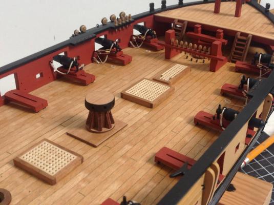
The wheel in place, finally.
A question still in debate: the rope for the wheel... Should I use 0,1 or 0,25 line for the rigging?
And something for the front platform: is it a major fault to leave it's gap (for the bowsprit) rectangular than to shape it in a semicircular fashion, like you did ?
I used 0.25mm rope, I also recommend winding the rope round the wheel and sealing with watered pva before anything is fixed in position.
Cheers,
Pete
-
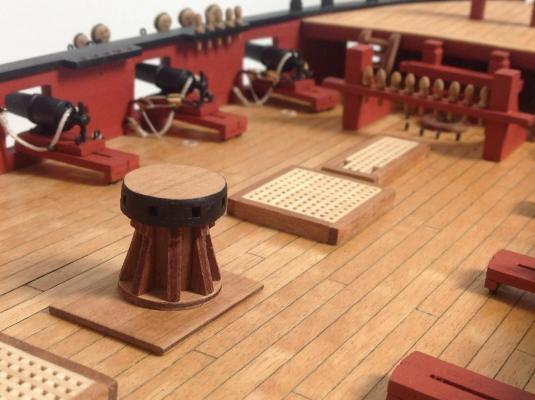
Great job on the cathead Jason. I was just wondering why you painted the capstan red, are there any examples of this throughout history? Or simply to hide the walnut ply?
I was looking at mine and didn't like the look of the ply layers so I painted the top part black (this part looked the worst) , what do you think?
-
Seeing as you asked nicely.....
These weren't very obvious from the plans and the eyelets around the main mast clashed with the pumps according to the drawings I had so I made a guess. It may or may not work but we shall see....
Do I detect sarcasm there Jim.... Sorry I should have asked more politely.
But Thankyou very much anyway, to be honest i wasn't even 100% sure that those were eyelets around the masts from looking at the plans, do you recommend putting them in sooner rather than later?
Cheers,
Pete
Oh and btw, good progress on the rigging, I remember the shrouds and ratlines taking me AGES on my pickle!...
-
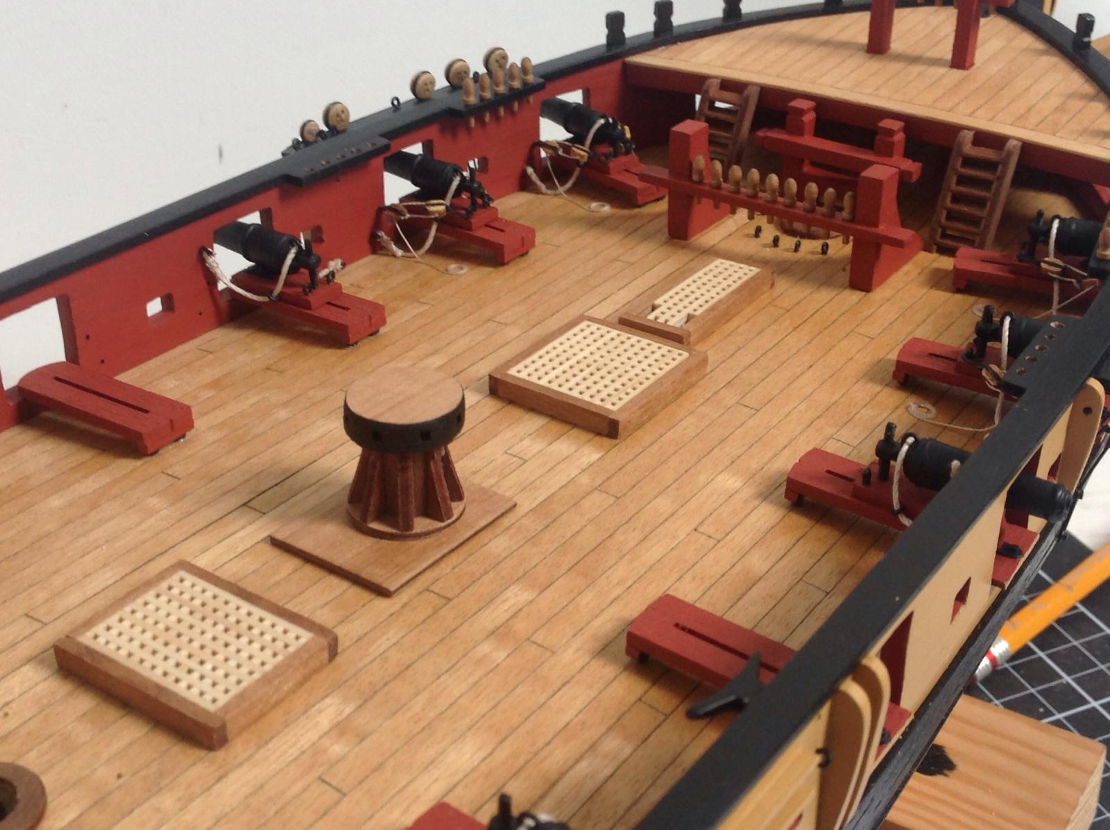
Please could I see a close up photo of the deck eyelets around the masts?
Cheers,
Pete
-
I'm not sure about cannon rigging, looks great to me though. Could I just ask did you apply oil/varnish to those belaying pins? The colour looks different to the ones of my pickle
Cheers,
Pete
-
Very good technique for ensuring the correct length of breaching rope, I shall adopt that for the rest of my 16 carronades!!
Cheers,
Pete
-
Wow, thanks for such a quick reply. Do you mean the panart kit includes more fittings or just the same fittings in a better quality? I know the scale is bigger, but it just seems too big a price difference considering its only 25cm longer?Pete, there is a huge difference in the kits. The Panart kit is the one to get if you can afford it as its a bigger scale and the fittings are superb. The Mantua kit is smaller and not as detailed.
-
Hi I'm looking around now at models for a potential future build. I like the look of the Amerigo Vespucci, however the pricing has confused me somewhat.
If you take a look at Panarts version it costs £670 (not including the £80 sail kit) @1:84 scale
http://www.cornwallmodelboats.co.uk/acatalog/amerigo_vespucci_741.html
Now at Mantuas kit, it only costs £295 ( not including the £80 sail kit) @1:100 scale
http://www.cornwallmodelboats.co.uk/acatalog/amerigo_vespucci_799.html
I don't understand why there is such a huge price difference considering the scales are only slightly different, and Panart kits are a brand of Mantua models, so I guess they are similar in quality?
If anyone could explain this to me that would be great!!
Cheers,
Pete
-
In the mean time I want to ask you:
1] do you like to have painted or blackened small parts like trunnions, eyelets etc
2] what kind of tool do you use to trim or precise cut metal rods of 1mm to 1,5 mm?
Thanks a lot!
1- I prefer to paint metal parts black after a first coat of metal primer.
2. I use metal pliers to cut the rod the a rough size ( sometime a hack saw if the rod is too big), then I use an English pattern pin vice to clamp it, and use a dremel type tool to sand/grind down each end flat and to a more accurate length.
Cheers,
Pete
-
Hi Pete,
Yes the rope is glued to the deck and the coil is made separately and placed over the end of the rope and glued down.
The rope seems to be unaffected by the PVA as it dries very translucent. Colour is still consistent with the unglued rope section.
Hope this helps
Jim
Yes that helps Thankyou, I will try using a different weaker glue and hopefully it won't change colour, also when you glue the rope coil down to the deck do you water it down or not?
And one last thing, over on my log I have asked about the side fenders, if possible could you try and help me?
Thanks!
Pete
-
Still working away producing tackle and now also creating rope coils for the deck.
Created a little rig to produce four coils at a go using board pins, rigging thread and a bit of pva watered down.
Just got to keep grinding away until it's all done.
Jim, do you glue the rope tackle to the deck first, and then separately glue the rope coil on top? Also do you find that the watered pva changes the colour of the rope?
Cheers,
Pete
-
Looking good Richard, good idea to paint the masts yellow, wish I did the same on my pickle rather than the walnut stain they reccomend. Same with painting the carronades red. looks neater and more even
Cheers,
Pete
-
I tried to paint the pin and hook before rigging the thread but found the paint just rubbed off anyway.
I always use a metal primer on all brass and copper parts that need painting, try that if you want to paint parts before fitting them. I then don't have any problems with paint rubbing off...
-
Nice, have you decided on the carronades yet...?
-
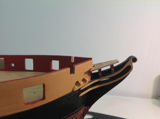
Did you not trim the aft of the bow grating (60) , as you can see in my photos below the gammoning slots in the grating do not match with the stem in the slightest ( unlike yours which is only 1-2mm out), and the forward head rail frame blocks the front of the gammoning slot in the bow grating. Although you might not have adjusted any other parts on you snake, do you think I need to adjust mine so that the bow grating sits further back??I think this picture at link below best illustrates it and attempts to explain. I found the slots needed to be enlarged to the rear only , don't think any adjustment is needed to the other parts. Hope this helps.
Thanks for you help!!
Pete

-
You can see in the picture below how even after fitting these, the bow grating does not lie correctly and would interfere with the bowsprit, simple adjustment to make but required a lot of dry fitting with the appropriate parts to get it to look right...
Hi Jason , please could you explain the adjustment you talk about above. Is it simply a matter of enlarging the slots or do you have the trim the vertical supporting parts to allow the bowsprit to fit?
-
Pete - Yes, I did trim the pintle, otherwise it wasn't possible to mount the rudder with the gudgeons already attached to the sternpost.
Thanks very much for all your help Jason, I should be able to complete the rudder after the rest of the coppering is complete!
Pete
-
My humble opinion is that there is probably little to be gained by filing down the rivets, you can get a pretty close fit as is which is really not noticeable - hadn't even really thought about it until you asked the question! Interesting idea, would love to see how you tackle it if you decide to go down that path. I think I'd be more worried about getting scratches on the copper plates.
The colour I used is Tamiya XF-52 Flat Earth - unfortunately my local store doesn't have much selection. I tried the Admiralty walnut but thought it too bright, and I'm not very good (I found) at mixing colours.
Ok thank you very much Jason. I have just been looking at my components for the rudder and they look slightly different to yours. Did you widen the recesses in the rudder and if so why ?
Pete
-
Hi Jason, I know that when you attached the straps to the rudder, you did not file down the rivets in on the tiles underneath the straps, however would you recommend doing that so that the straps lie more flush? I was also wondering if you painted all of the ships wheel brown including the stand, and was that in walnut brown from caldercraft? Thanks very much,Started to tackle what is really the last task to be done before I can safely keep the old girl permanently on her keel and start getting the deck fitted out...installing the straps.
The instructions are very light in this area and it took me quite a while to figure out a system. I only have one side of the rudder complete at this point, but started on the rudder as I thought it would be easier to handle and build skills before tackling the hull straps. I was concerned with the pins protruding too far as I assume that these would probably have been flush, but I'm not sure its possible to achieve that with the supplied materials. I was pretty pleased with the result, the pins don't seem to be any more noticeable than the nail heads on the plates.
Heres how I tackled it...hopefully I haven't made any newbie gaffs:
- Prepainted the straps with metal primer and copper paint
- Marked the center point of the rear of the strap and pre-bent on a piece of 3mm dowel
- Spot glued the strap to the pintle only
- Once I'd ensured the strap was perpendicular to the forward edge of the rudder, drilled a small (0.6mm) hole in both of the end holes (found the smaller bits drilled through the copper more easily). This seemed to secure the strap sufficiently to be able to work on the rest
- Enlarged the hole to 0.8mm (If positioned correctly, the hole from opposite sides will meet)
- Enlarged the strap hole further to 1.0mm to allow the pin head to be countersunk to some degree
- Using the brass pins supplied (couldn't find any others I should use), I cut these down approximately half the thickness of the rudder, put thick CA glue on the bottom of the pin and inserted into the hole
Pete
-
Hi Pete,
Off the top of my head I seem to remember 0.25mm for the tackle lines and 0.75mm for the breaching rope.
Thanks Jim !
-
Hi Jim, your build is looking great, please could you tell me the thickness of the two ropes that you used for the carronades.
Cheers,
Pete
-
The carronades do sit up rather high, higher than cannons, and on this ship the 32lb'ers are pretty big for the ship. Its the same with the aftermarket ones as well. A lot of this gets driven right back when the gun port patterns were installed and the relative height to the deck, seems even a 1mm difference can make a huge difference with the room for the carronades.
I might be mistaken, but I am sure that would only alter the angle of the carronade and wouldn't make any difference to the gap that is left. Because the reason it does not fit is because of the distance between the gunport sill and the top of the gunport not being big enough?
Pete


HMS Snake by jim_smits - Caldercraft - First Build
in - Kit build logs for subjects built from 1751 - 1800
Posted
Oh yes, there are quite a lot, what one of the bases did you go for specifically and did you apply your own varnish to it?
Cheers,
Pete