Search the Community
Showing results for tags 'galilee'.
Found 8 results
-
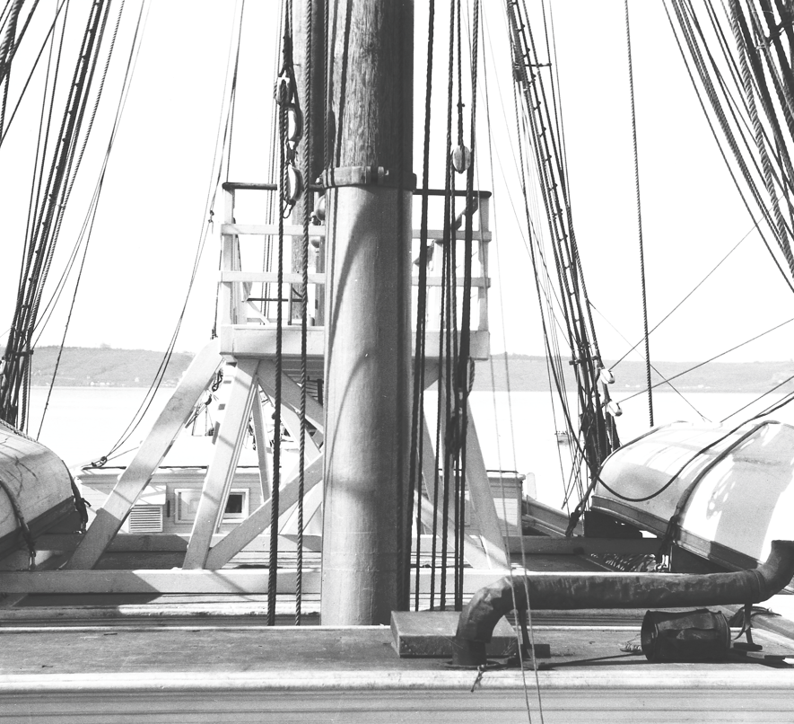
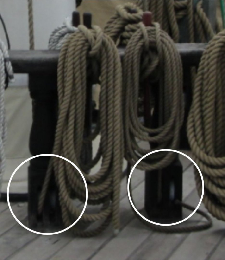
 This is a research question on the structure and arrangement of fife rails constructed in smaller American merchant ships of the late 19th century. This question specifically pertains to the 1891 American West Coast brigantine packet ship Galilee, which is the subject of my topic found here in the Model Ship World forum. I specifically wish to understand the basic structure of a "partial" fife rail. Galilee’s original forecastle was constructed just aft of the foremast and so close to it that the sides of the mast’s fife rail evidently were attached to the forward bulkhead and were spanned by a transverse rail forward of the mast. Two corner posts evidently supported the forward section of the rail. No details as to the number of belaying pins or other features of this structure were provided. The following image was taken from the plans of Galilee produced by G.C. Berger of the former Pacific Marine Research Society* in San Francisco sometime during the mid-1930s or later. The foremast fife rail in the brigantine Galilee from the plans of the ship produced by G.C. Berger some time after the mid-1930s. I obtained this plan through the National Park Service in San Francisco One feature often seen in online photos and illustrations of fife rails is the presence of sheaves in the corner pedestals. Were these sheaves associated with specific types of running rigging that would be applicable to the square-rigged foremast in a brigantine? Would they have even been required for a relatively small packet ship? Cropped photo of the mainmast fiferail sheaves in USS Constellation, Baltimore Harbor, April, 2012. (Photo by Joel Abroad via flickr. Some rights reserved.) The following is the best photo I have of Galilee showing the various halyards, etc., that were evidently secured at the unseen fife rail. Since I am not really conversant about the kinds of running rigging such a ship would have, I can’t tell what each of these lines would go to. Would any of these have required sheaves in fiferail pedestals? Lower foremast of the brigantine Galilee showing the few lines of running rigging leading to the fife rail at its base. Most of the upper running rigging lines ran down to the main pin rails through thimbles(?) attached to the shrouds. (Courtesy of the Carnegie Science Library, c. 1906) Any assistance finding illustrative examples of such a fife rail would be appreciated. I have already done due diligence in trying to find examples on the Web and within the MSW site using keyword and image searches, but there is very little information on this topic and virtually nothing showing the kind of fife rail I am looking for. Thanks. Terry *The "Pacific Marine Research Society" was formerly called the "Pacific Model Society," whose founding was "to encourage the preservation of Pacific Coast maritime lore." ( From the Senate committee record Maritime museum; Stones River National Battlefield; Western Historic Trails Center; and Pinelands National Reserve Visitors Center: hearing before the Subcommittee on Public Lands, National Parks, and Forests of the Committee on Energy and Natural Resources, United States Senate, One Hundredth Congress...Vol 4; GPO, 1988.) This is the only reference I could find to the organization itself on the Internet. Some records from the Society remain.—RTE
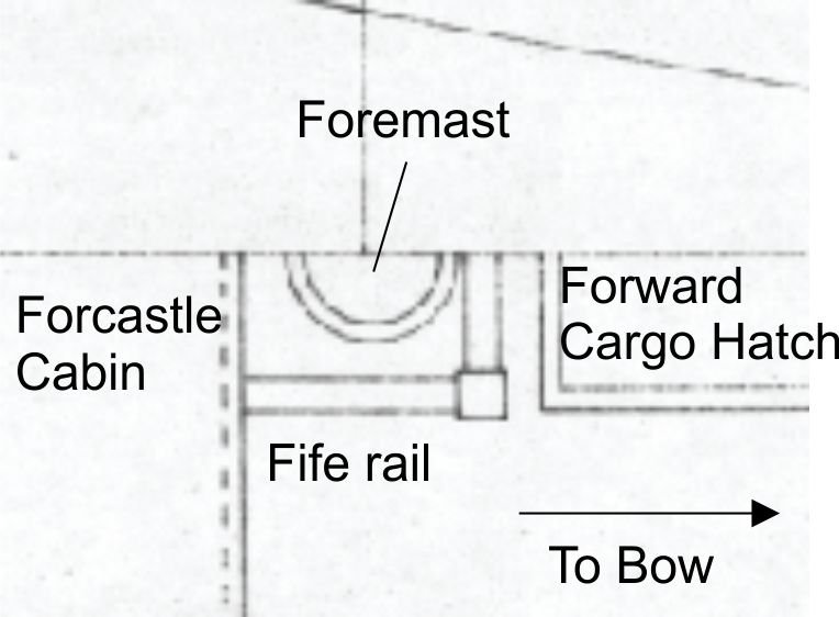
-
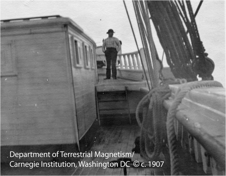
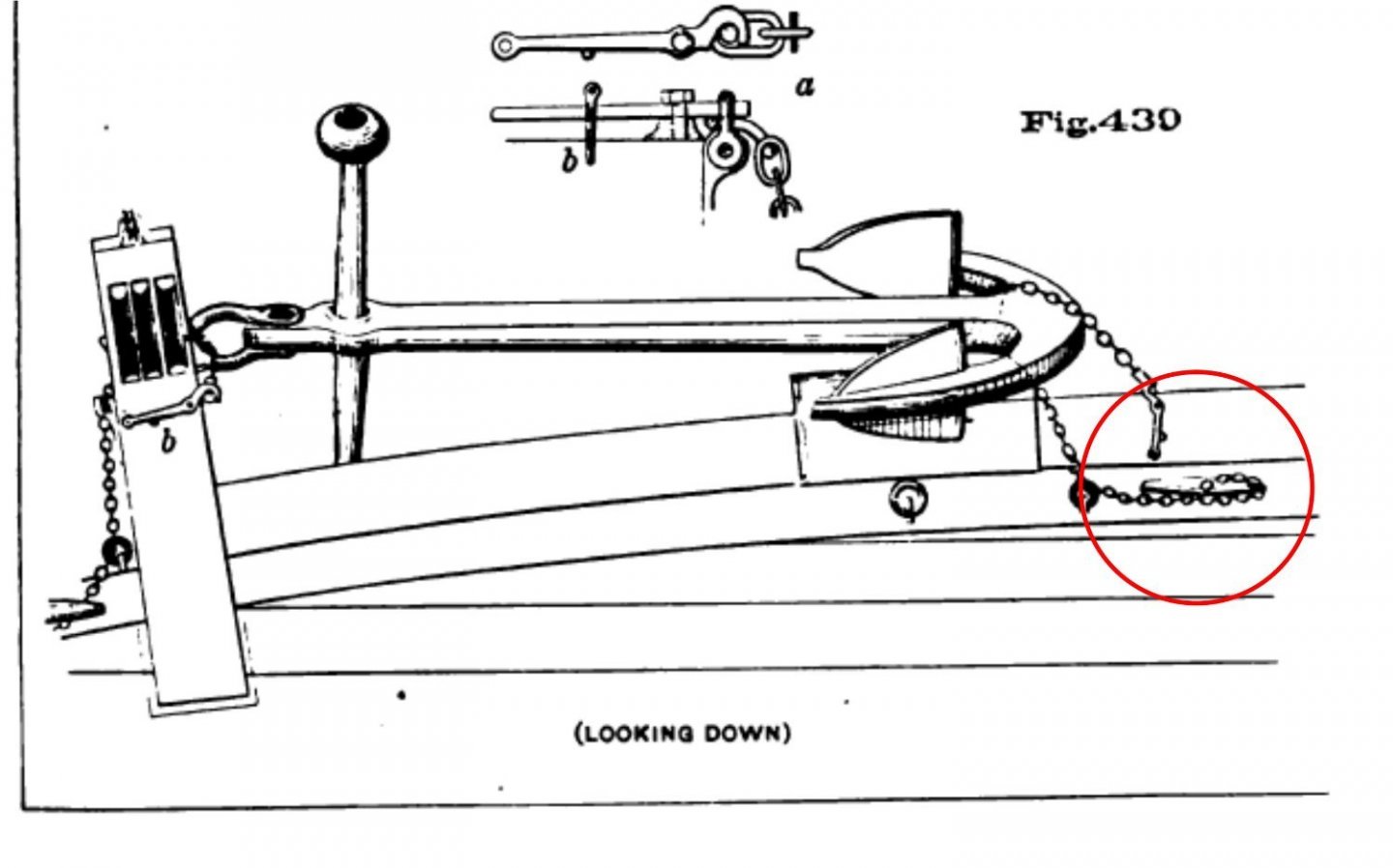
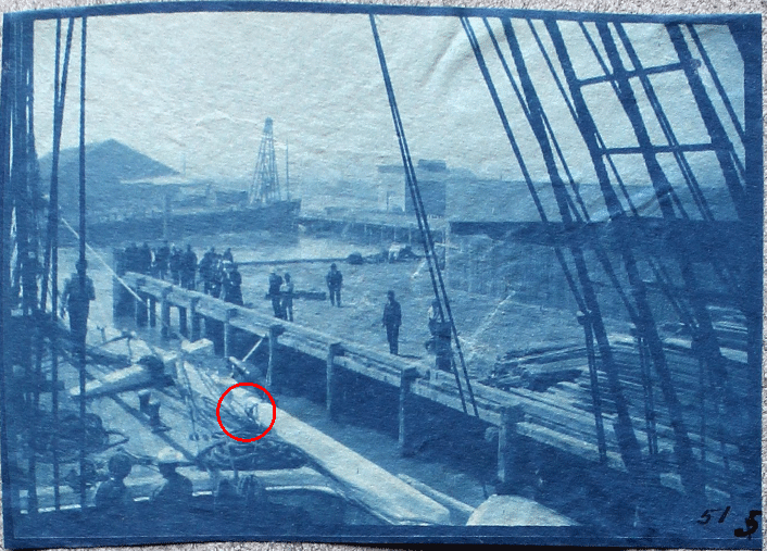
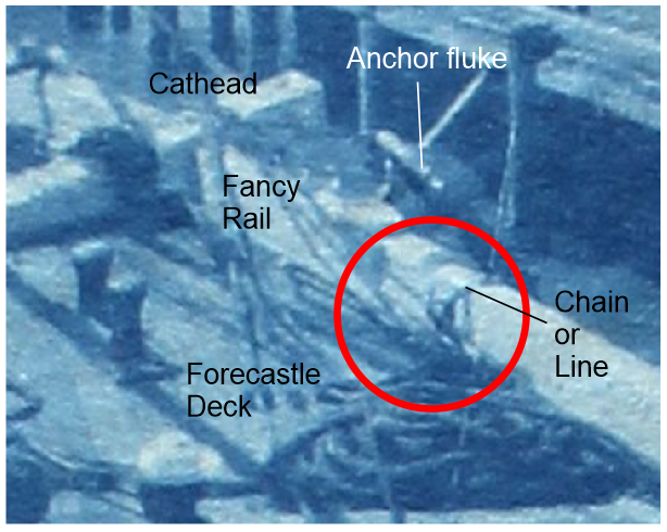
This topic pertains to the proper securing of bower anchors in latter 19th-century merchant ships. I have several poor-quality photos of the foredeck of a brigantine merchant ship (the Galilee) taken sometime during 1905–1908, showing how her anchors were secured when underway. This is probably the best of the lot. Photo showing the brigantine Galilee being fitted out as a geomagnetic research vessel in 1905, probably somewhere in the vicinity of San Francisco Bay, California. The circled area is where the chains/lines securing the lower end of the anchor were tied off. (This and following photos Courtesy of the Carnegie Science Library.) Closeup of the area circled in the above photo. I am in the process of adding the remaining deck furniture and fittings to my digital model of Galilee. My questions pertain to the size, shape, and orientation of the cleats evidently used to secure the lower end of the anchors. What would be the size of the cleat? I've seen the rule of 1 inch of cleat length per 1/16 inch of line diameter. However, in many diagrams showing stowed anchors, it is small chain that was used for this purpose. So, what is the rule if chain is used? Galilee's anchors would have been a minimum of 600 lb. each, about half of which would have been borne by the anchor cleat. Would this have been a factor in selecting the cleat size? Determining the likely shape of the cleat is important for a historically-accurate model. I have found a source of so-called "antique" cleats here. The shapes are quite varied as one can see. Would the type most likely be just a basic cleat such as this one? I have read about—and also experienced—the proper orientation of lines taken to mooring cleats. Typically, the line secured to a cleat should run horizontally perpendicular (or tangentially) to the cleat. Cleats are weakest when the tension pulls upward. So would a cleat securing an anchor likely be bolted to side of a rail or to the deck adjacent to the rail? The latter configuration would result in a more upward tension. However, Figure 430 in Plate 94 of the USNA's Text-book of Seamanship (Luce, 1884) suggests this could have been the case. Diagram of the method for securing a bower anchor in a mid-19th-century warship from the cited USNA reference. The circled cleat appears to be fastened to the deck or a waterway. (The image is found in Plate 94 located between pages 246 and 247.) Any comment or directions to other sources to resolve these questions would be very much appreciated. Terry
- 5 replies
-
- 2
-

-
- anchor cleat
- brigantine
- (and 3 more)
-
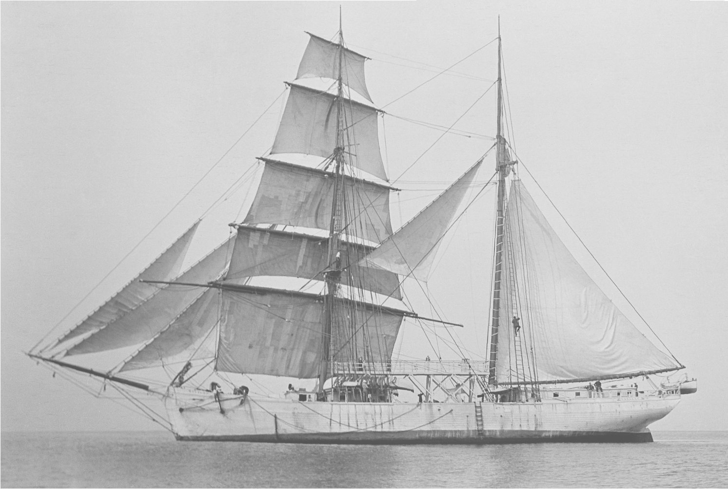
This Fall has been busy with many birthday and Christmas projects, and the resumption of homeschool with my grandchildren. So not much time has been available for work on Galilee's plans. However, a recent topic regarding gaff-rigged sails in this forum reminded me that I haven't been able to identify Galilee's mainsail type. Basically, it is a leg-of-mutton sail headed by a short spar. The not-so-all-knowing Internet claims that brigantines and hermaphrodite brigs all carry/carried a gaff-headed mainsail. Here is Galilee in all her glory, courtesy of the Carnegie Science Library: So, what is this kind of mainsail called? Thanks in advance for your assistance. Terry

- 8 replies
-
- 3
-
-
- Brigantine
- 1800s
- (and 3 more)
-
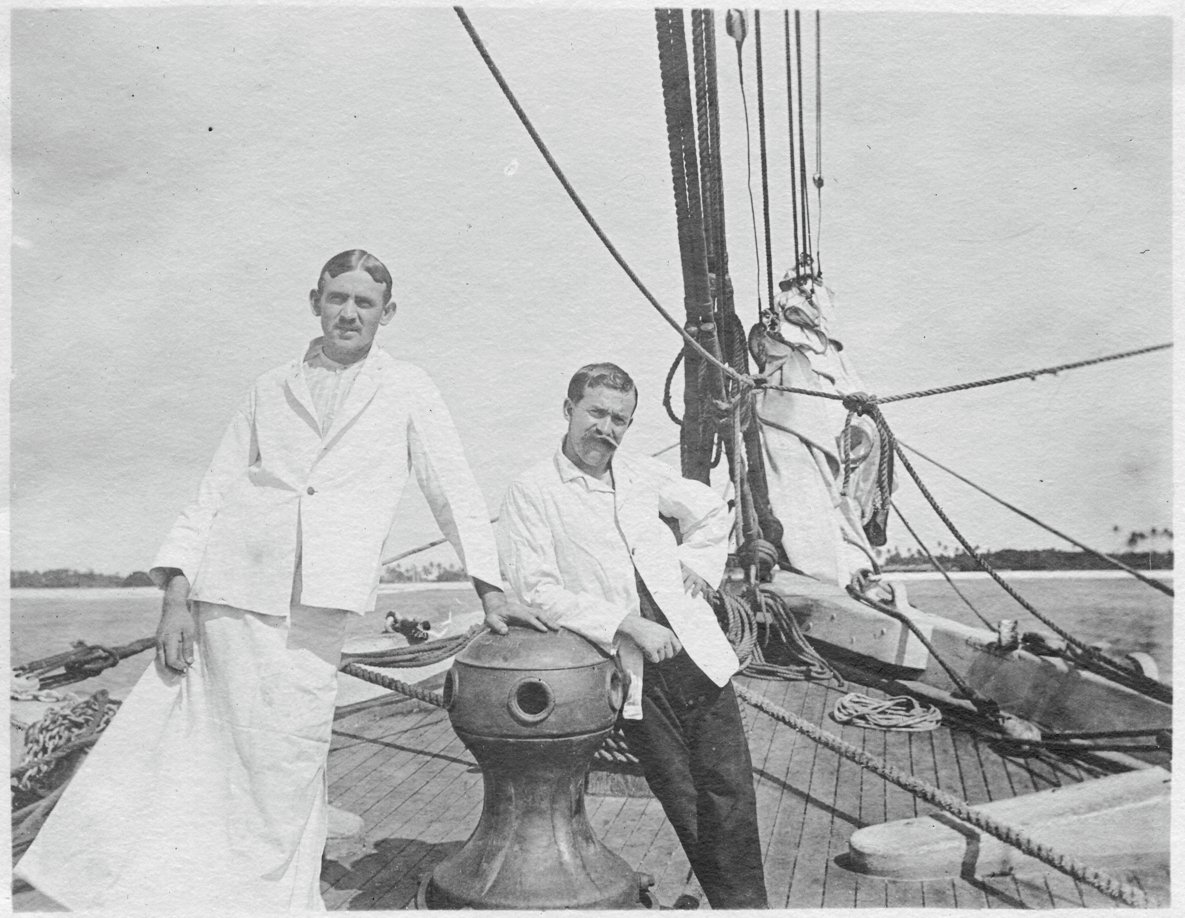
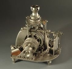
Hello, All. I've been searching for any plans/photos/schematics of a Hyde Windlass Company (HWC) hand capstan and windlass assembly. This would be sized for a 350-ton sailing merchant around 1890. The brigantine Galilee was launched in 1891 in California and seems to have been equipped with a Hyde capstan (see the photo below). Photo courtesy of the Department of Terrestrial Magnetism, Carnegie Institution, Washington DC (c. 1907) (The attire of the men is somewhat strange. The research crew's surgeon is on the right and his steward/surgical assistant is dressed for surgery.) What I really need is some information about the windlass, which was located in the open forecastle under the deck. I would like to render this equipment as accurately as possible, since it will be visible in the finished model. An entire windlass/capstan assembly has been modeled; its images are available on the Web. However, all that i have been able to find are steam windlasses, like the one shown here. Galilee's windlass was strictly manual. I have already contacted the Maine Maritime Museum in Bath, ME. They have some extensive archives pertaining to the HWC (which became the Bath Iron Works Shipyard), but their staff is limited and they haven't been able to find what I need so far. If any members live in or near Bath and would like to look into this, I would be very grateful. Terry

- 21 replies
-
- 2
-
-
- capstan
- hand windlass
- (and 3 more)
-
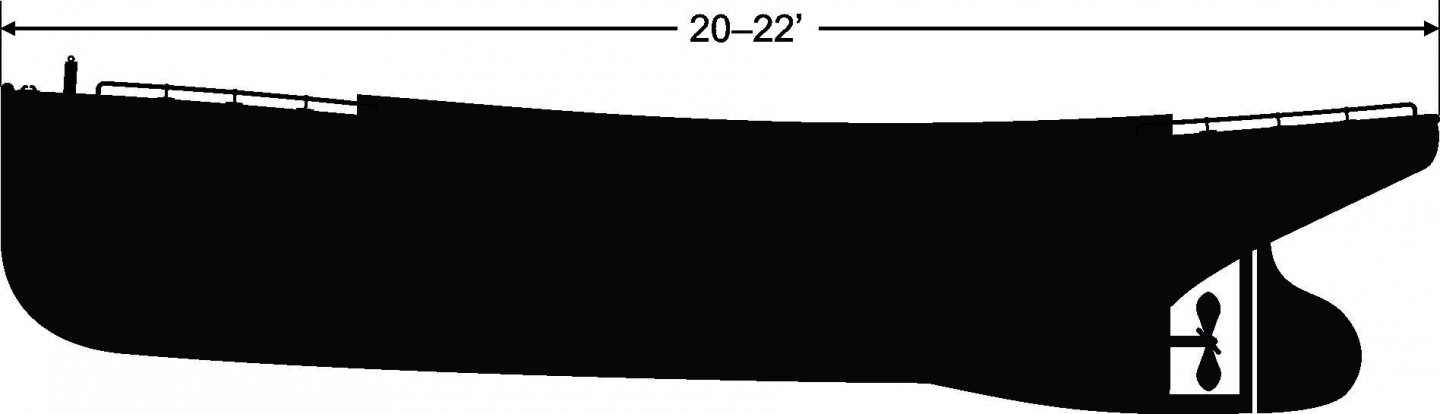
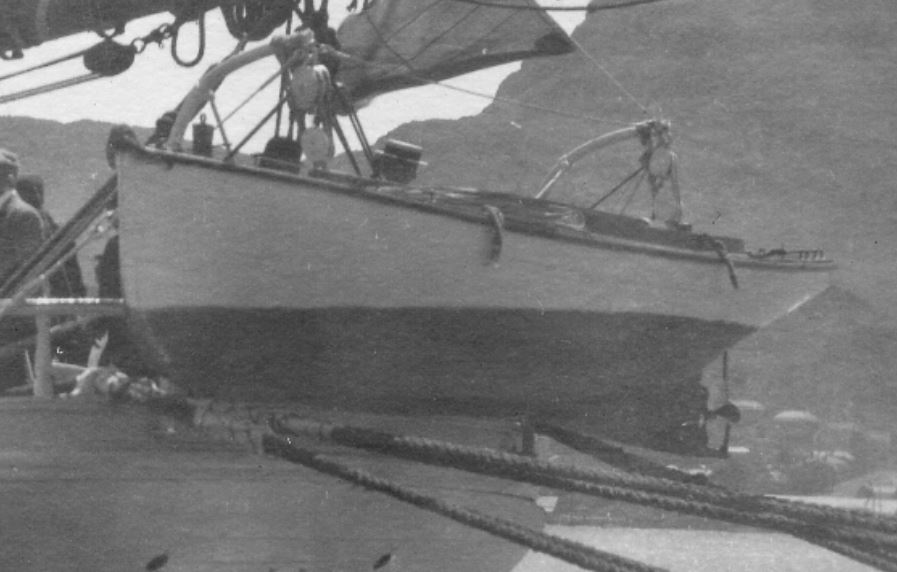
Evidently this particular "boat" topic has never been brought up in this forum. Late in the 1800s when builders were toying around with more compact and energetic sources of energy for propulsion, they developed the naphtha engine, which used volatile fuels produced by the distillation of petroleum to either heat water to steam or, eventually, to produce propulsion by internal combustion. It was the precursor to gasoline engines. Between the 1890s and around 1905, small- to medium-sized vessels called naphtha launches were very popular with the boating public, and thousands were built by companies such as the Gas Engine and Power Company for recreational and commercial use. Now to my question: The brigantine Galilee, in which my grandfather sailed, was conducting magnetic surveys of the Pacific Ocean between 1905 and 1908. Because the vessel was not entirely nonmagnetic due to the hundreds of iron fasteners in her hull and some steel and iron rigging components that couldn't be removed, she produced a small by measurable magnetic characteristic that had to be accounted for in the sensitive measurements and calculations of the earth's magnetic field. This was accomplished by measuring the earth's field elements on various courses at sea, and turning the ship in harbors at the ports she visited. The former was done using wind, sails, and rudder. But the latter was very difficult without outside assistance, and very time consuming. To deal with this problem, on her second and third cruises, she was equipped with her very own—naphtha (or more probably, gasoline) launch—carried in beefed up davits off her stern. Sadly, I don't have very many photos of the launch to finalize my reconstruction of the plans for the ship. Courtesy Department of Terrestrial Magnetism, Carnegie Institution, Washington, DC This is an approximation of what I can see: According to various sources, the boat is described as a plumb-bow fantail launch. My best approximation of its length is about 20–22 feet long. Its depth is about 4 to 5 feet. I have no idea of the beam, since there are no views of this detail. I don't even know if there is a transom or if the stern is elliptical or canoe-shaped, like many of the available plans of this type of vessel show. If anyone knows of sources that show either this particular type of launch or one similar to it, I'd appreciate direction to them. I've already checked out most of the diagrams available on the web, but if there is one that looks close to this boat, and in particular shows the plan and body views, those would be of great help. Terry
-
Hi all. Anyone know of an authoritative reference showing late 19th-century merchant pinrail diagrams? It is my understanding that belaying pin arrangements were fairly standardized by ship-type throughout most of the world, or at least within a nation's fleet, so that crew could be hired in nearly any port and would be able to serve with little additional training. I am looking specifically for the pinrail layout typical of a late-19th century, West-Coast, brigantine merchant of medium size. Any assistance will be appreciated. Terry Egolf Colorado Springs, CO, USA
- 6 replies
-
- 1
-
-
- merchant
- brigantine
- (and 8 more)
-
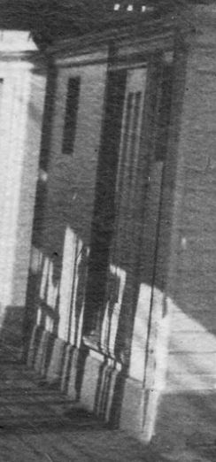
Need some help interpreting what I am seeing here. In the attached photo of Galilee's middle deckhouse port side, there is evidently a sliding door mounted on wheel tracks top and bottom. Here are some questions: How was such a door made reasonably weatherproof? Would there be water stops built into the frame to prevent major water intrusions during boarding seas? Would the door handle/latch be a lever or just a hand grab like a staple? As you can see, the photo is pretty muddy where a handle would be. There is a suggestion of a vertical metal rib along the forward edge of the doorway, which might be a water stop. Like all sliding doors on ships in my experience, there was probably a standing latch when the door was fully open and a latch when it was shut. I have no idea if technology of the late 1800s would have produced a mechanism that would operate both latches. If anyone has reference photos or other images of such an installation, I'd appreciate seeing them. Thanks. Terry
- 11 replies
-
- 2
-
-
- 19th century
- Galilee
- (and 6 more)
-
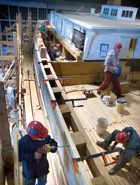
As I am moving into the details of deck furniture, deck houses, and the poop and forecastle decks in Galilee, it occurred to me that I had no idea whether the main deck in a basic sailing merchant ship extends the full length of the hull, including under the poop and forecastle decks. The remains of Galilee's bow at Benicia Historical Museum suggest that the main deck was planked all the way to the stem. But what about at the stern? Galilee had a low poop deck about 4 feet above the main deck surrounding the aft end of the main cabin (see photo below). The helm and main boom traveler were located right aft and the companionway to the captain's cabin was via a short stairway from the poop deck to the cabin deck, which appears to be at the main deck level. So, did the main deck planking continue aft to the fantail under the poop deck? I found a photo of the lumber schooner C. A. Thayer in San Francisco during her recent renovation showing what appears to be workers standing on the main deck while reinstalling the aft cabin and constructing the poop deck framing (see bottom photo). Would this be typical of merchant vessels c. 1900? If so, what was the dead space under the poop deck used for? Was this part of the lazarette space? Terry