Search the Community
Showing results for tags 'yards'.
Found 6 results
-
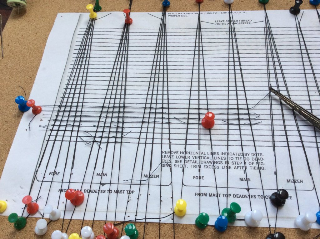
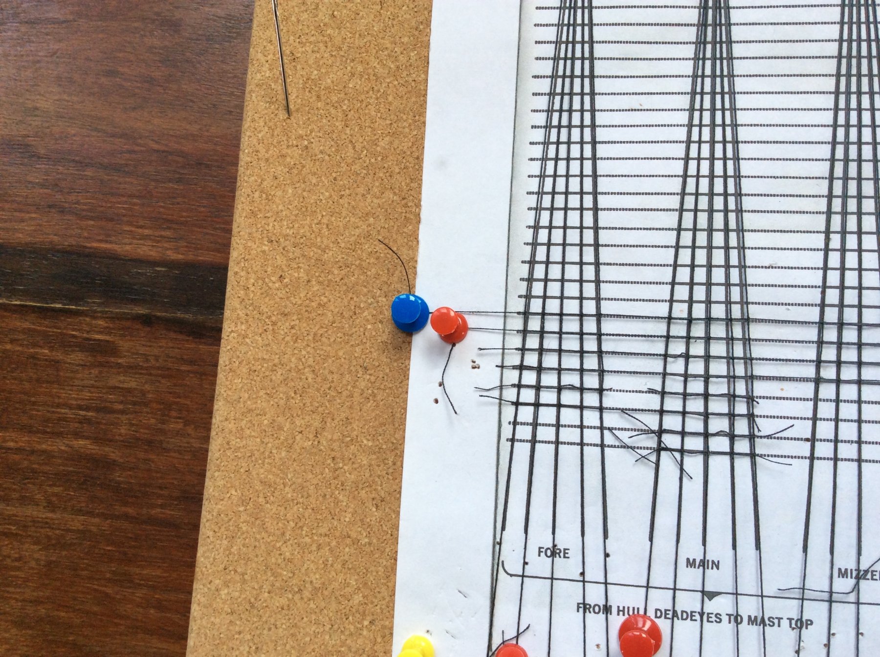
Hi all, I'm in the middle of building the Revell Cutty Sark. Have had the kit stored for about 15 years so thought it was about time to take it out of the box. Basic hull and mast construction is complete and though the colour scheme may not be true to life, many ships changed parts of their colour scheme during their service so I make no apologies. One of the worst aspects of the model is the amount of flash and the filing that has to be done to remove excess material - very time consuming. However, it's not too much of a problem to get the parts to fit. This brings me on to sequencing and here I think the instructions could be improved. For instance, I would do as much rigging work as possible before attaching the spars to the masts. Most of the Standing Rigging is in place including the Ratlines, a lot easier to do than working your way over and under the spars. Incidentally, the ratlines are all hand knotted and the way I did them, setting them up on a frame, prevents the "hourglass" shape which some folk have mentioned. You can see this in the pictures; I've used the template supplied with the model and stretched the vertical threads using map pins to hold in place. Then again using map pins to hold it in place, I start the horizontal threads with the tension maintained. This way, you can complete the ratlines for one side of the model just by working across the template, then repeat for the second side. I'm just about to start the sails and running rigging and would appreciate advice on whether to glue the yards to the masts and then attach the sails, blocks, etc.. Or attach the sails, blocks, and so on to the yards first, and then mount the sub-assembly to the mast. I reckon it would also be sensible to work from the deck upwards rather than top downwards. Any ideas welcome guys, thanks.

-
A member of my model club asked me a question about why yards on square-rigged sailing ships were sometimes skewed at severe angles to their masts. He mentioned that he's seen this unusual aspect in various historic paintings of square-rigged sailing ships in harbors. I told him all that I knew - which is that this was a practice to signify that a senior officer aboard the ship had died. I believe this practice (ritual) was only done while the ship was anchored in harbor, for obvious reasons. Can anyone confirm when and where this practice originated and whether or not countries other than England also practiced this display? Also, can anyone add more details about the practice and if, in fact, it was always called "cockabill?” Thanks! Ron
- 5 replies
-
- 4
-

-
- yards
- death of an officer
- (and 1 more)
-
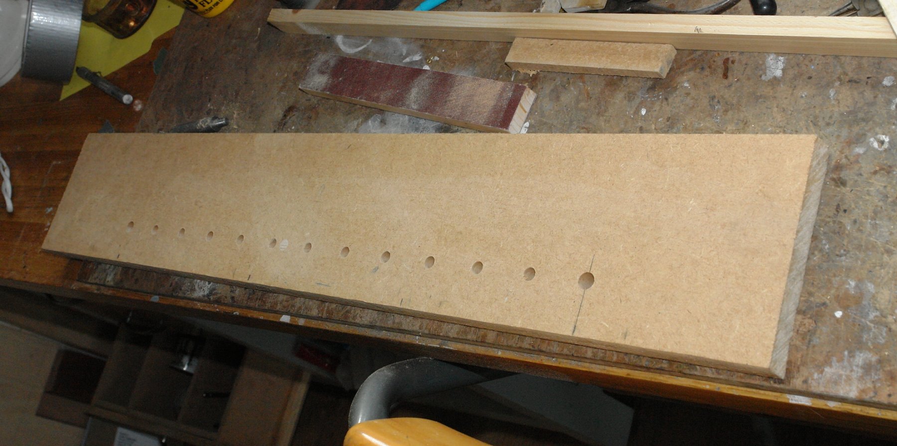
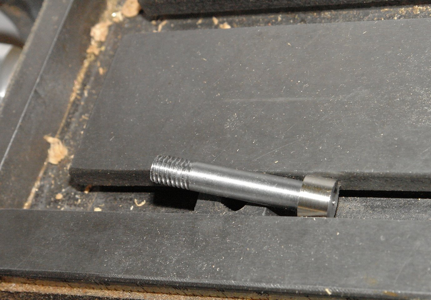
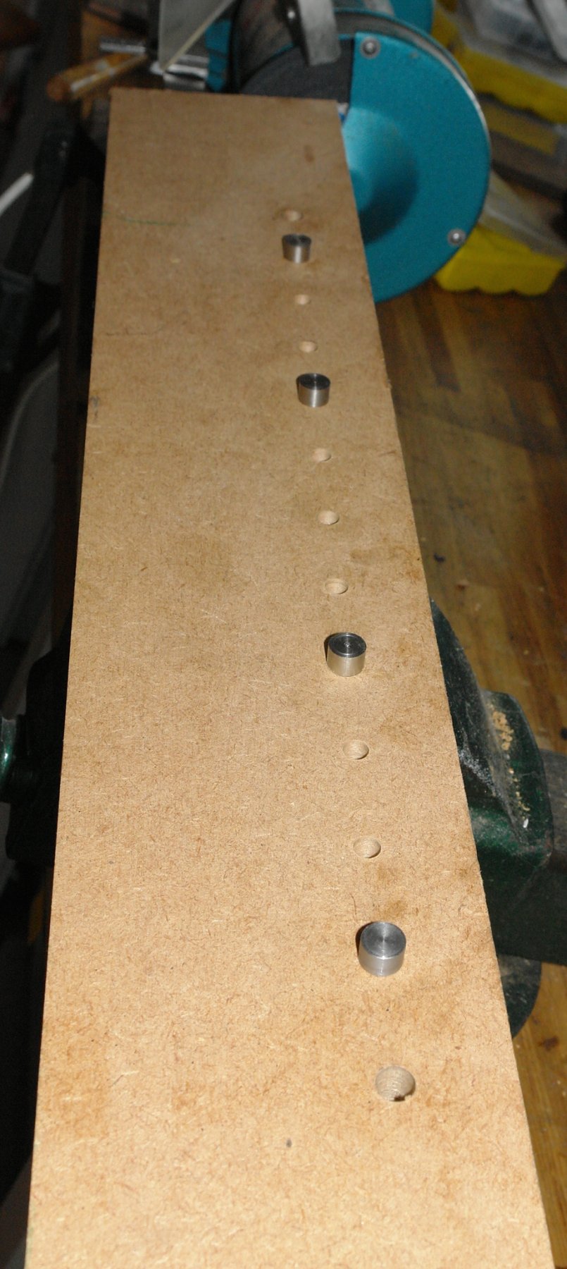
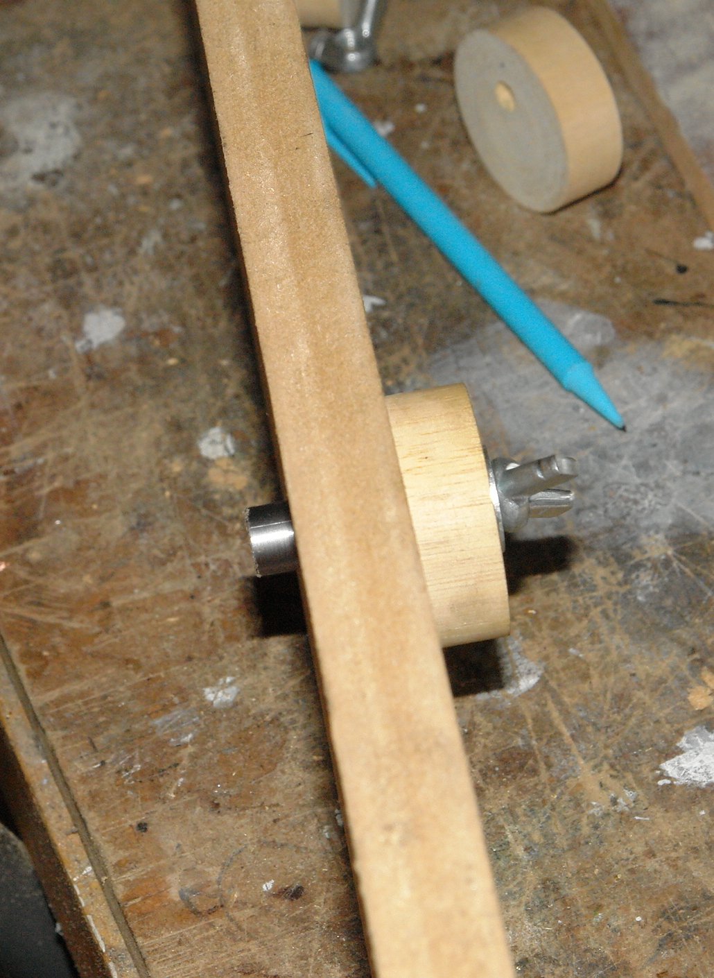
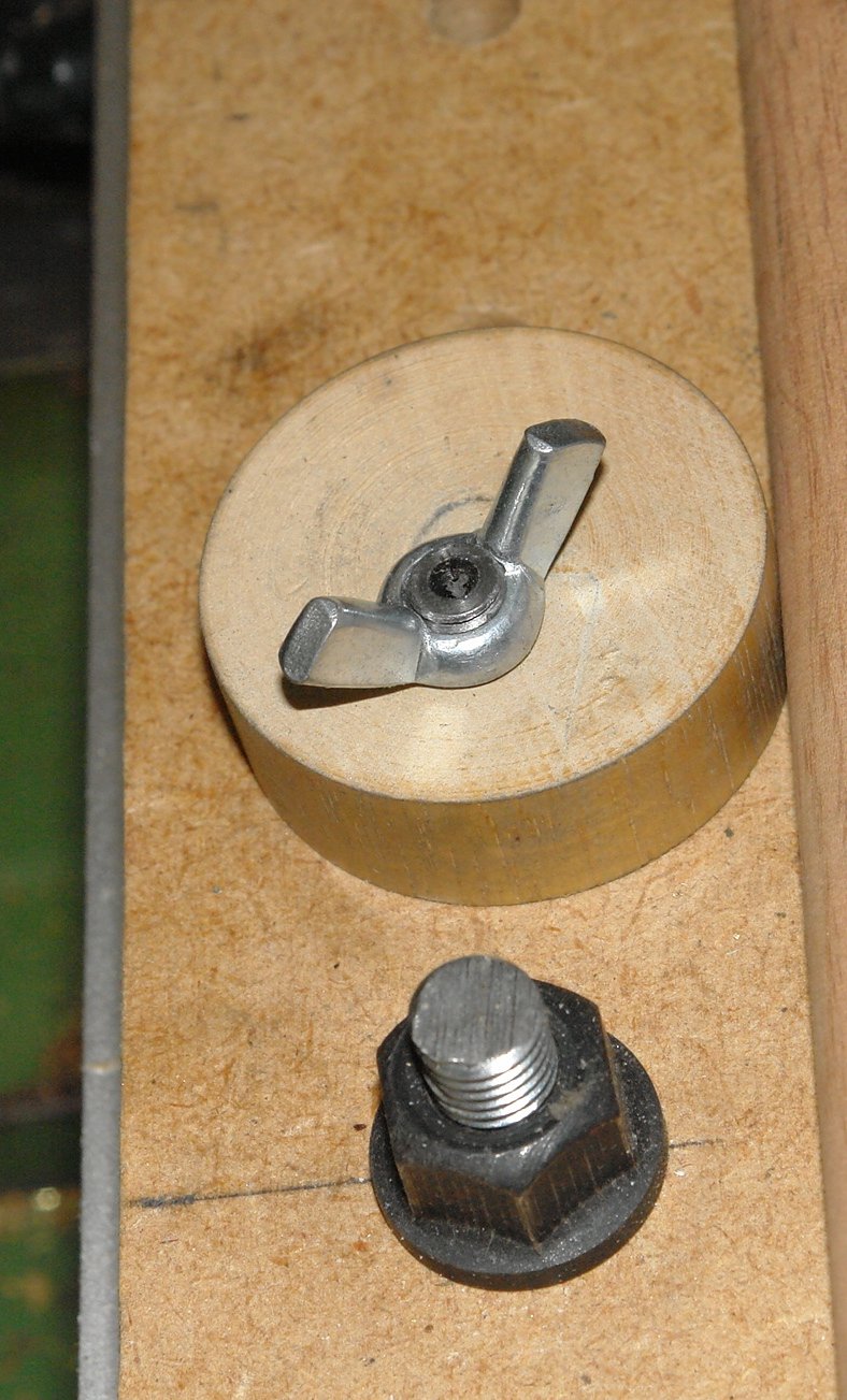
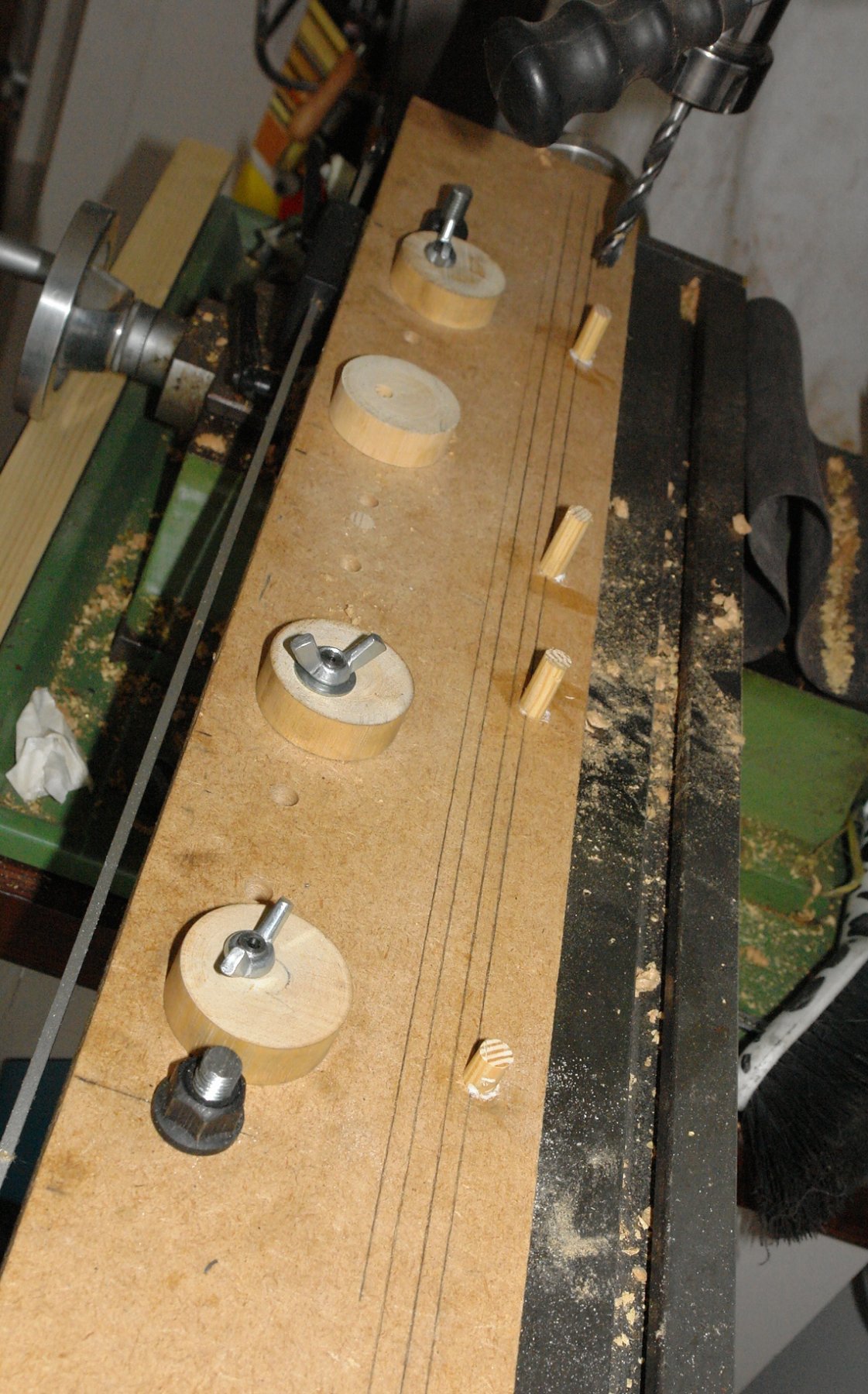
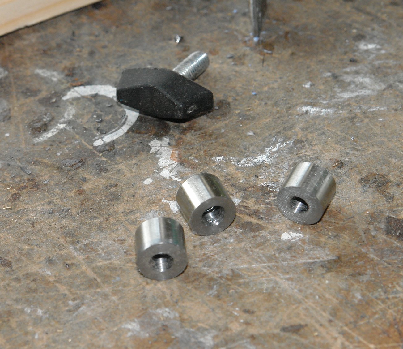
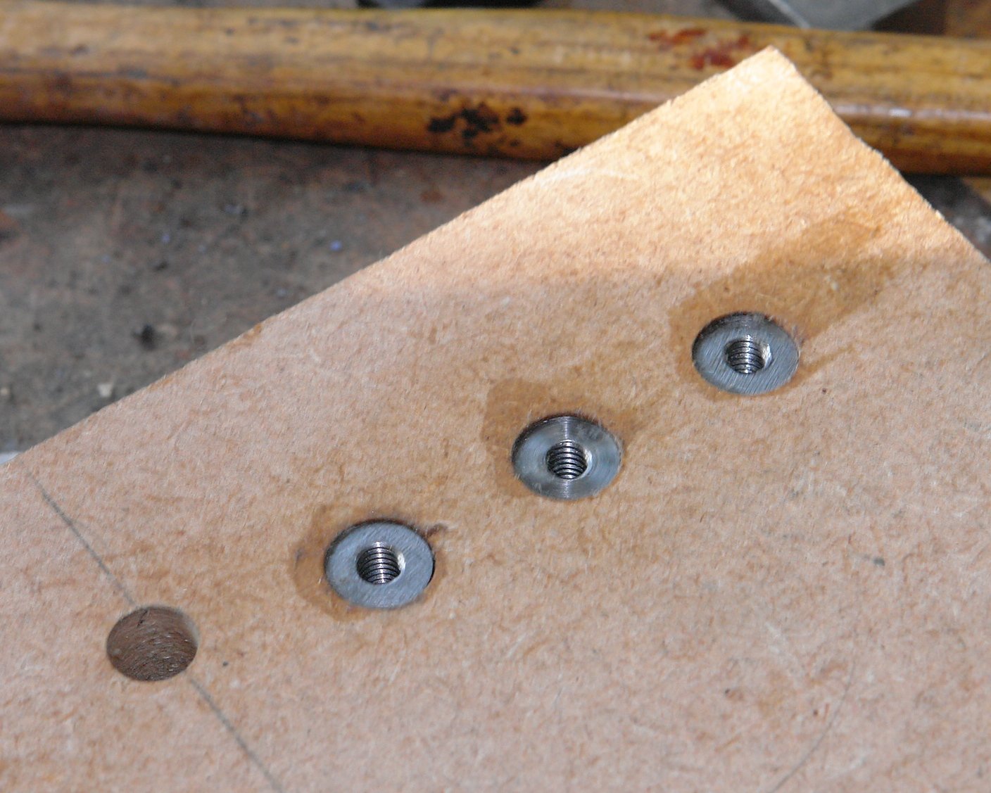
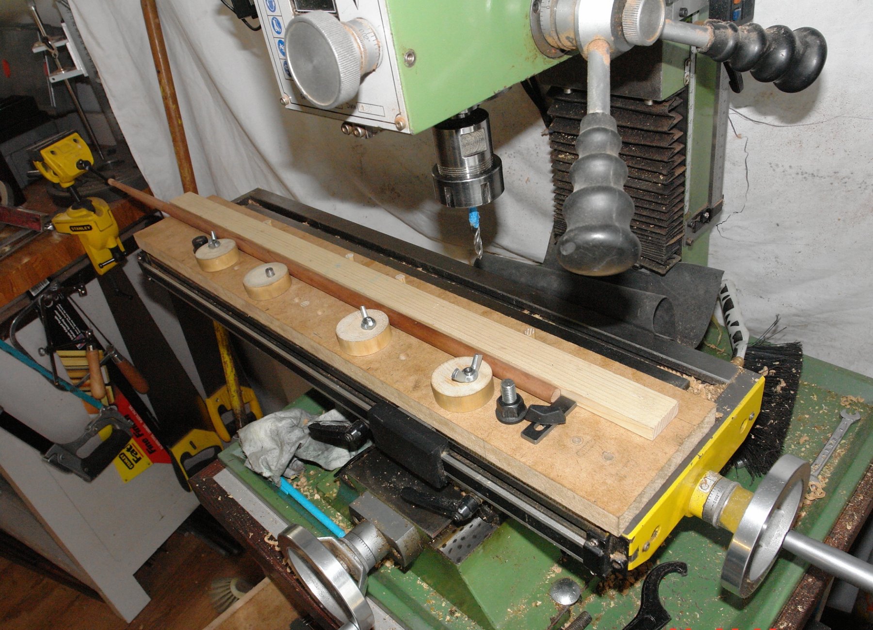
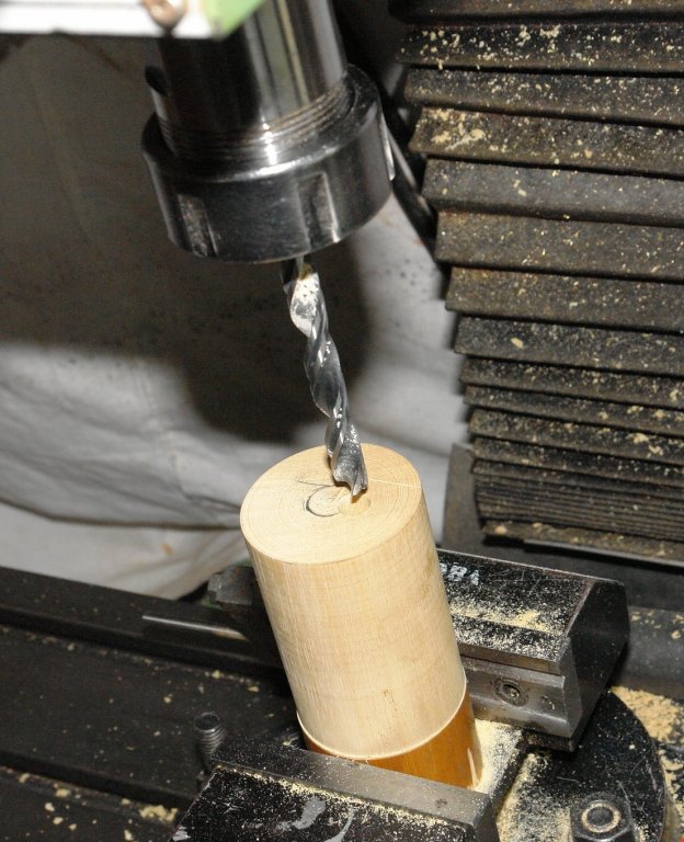
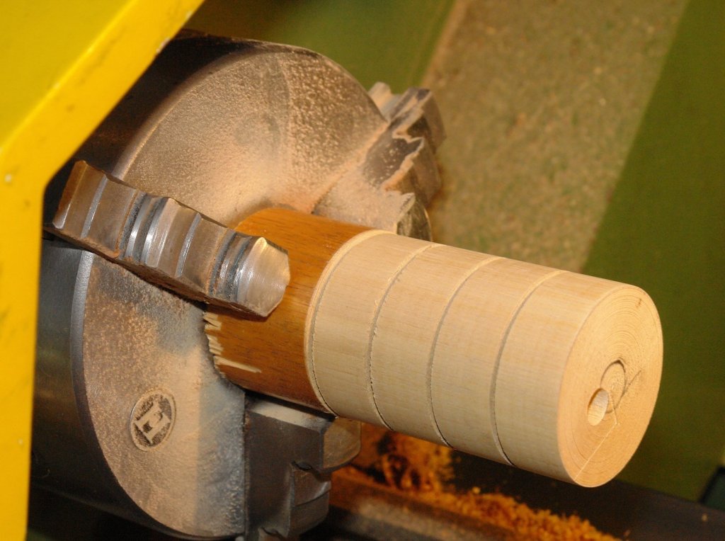
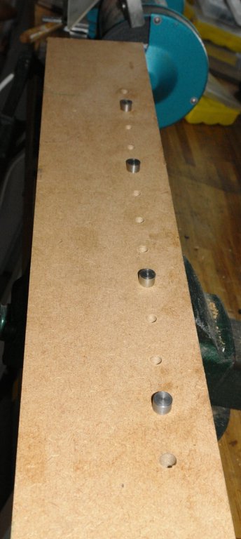
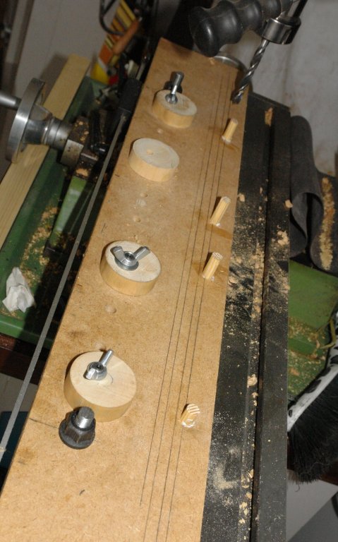
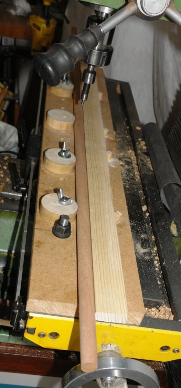
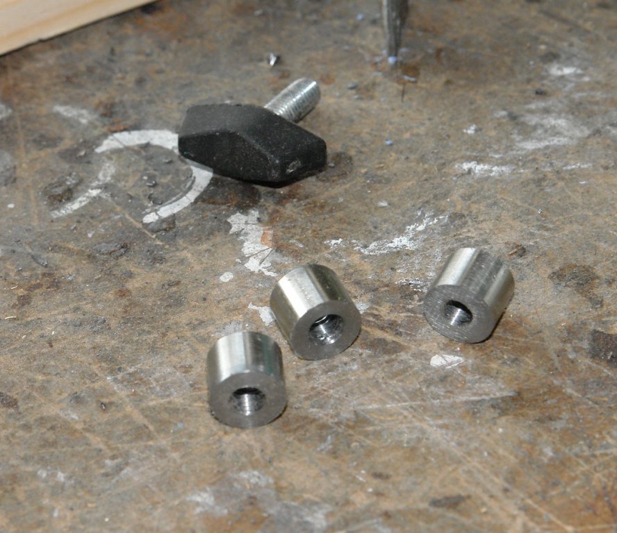
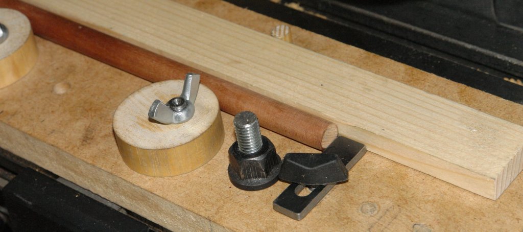
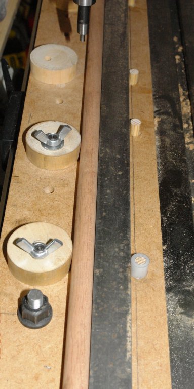
 In the past I have constructed many ad hoc fixtures to enable the accurate machining of masts, spars, yards, booms etc. I decided to have a go at making something more versatile that would work for items of different shapes and sizes. Having made it it seems to work well so I thought it would be worth sharing. I started out with a set of design aspirations. For ease I will refer to "masts" rather than go through the full range of parts each time. 1 Provide solid clamping along the length of the mast. 2 Locate / relocate on the milling table without the need for alignment / set up. 3 Positively locate and relocate the mast so that I can easily remove and replace it on the mill. 4 Clamping devices not to mark / damage the mast. 5 Clamp parallel and taper masts. 6 Clamps to be easy and quick to operate. I started with a clamping concept based upon eccentric circular cams and the build started by cutting a piece of 3/4" MDF to sit on the milling table. I used the mill to accurately drill a series of holes along the length of the MDF to take the cams. The cams themselves were turned (circular) from hardwood. An eccentric hole was drilled along the axis of the cams before they were separated. The cams are mounted on the MDF using a pin. The pin protrudes below the bottom surface of the MDF and the protruding part is cut to a diameter .001" smaller than the slot in the milling table. Once the pins are pushed into the MDF they give positive and repeatable location on the milling bed. The top of the pin locates the cam which is locked by a wing nut. The additional holes allow the cam positions to be varied to suit the mast being worked on. Holes at either end of the MDF take the "T" nut bolts which attach the MDF to the milling table. The MDF was then placed on the milling table (located by the pins) and a row of 4 holes were drilled parallel to the pin holes. Into these holes were placed accurately made dowels. These dowels provide the "fixed" support against which the cams clamp. I think this will become clearer in later photos. A simple piece of wood is then placed up against the dowels. This forms the face against which the mast is clamped. In the following picture a mast is clamped in place. Because the cams act as a finely tapered wedge hand rotation is enough to very rigidly hold the mast. The cams give a lot of flexibility on the diameter of mast that can be held - .200" to .700". But larger is possible by using a narrower wooden strip. At this stage I checked the alignment of the mast to the axis of the mill. The run out was .0015" over a 12" length. Much better than I expected. I did however need an end stop to control the position of the end of the mast. This was relatively easily achieved and for good measure I included an option for 3 positions. See Photos:- The solution to dealing with taper masts is straightforward but does require a bit of trigonometry. The taper is achieved by changing the diameter of one of the fixed dowels. This is done by making a collar to fit over it. This gives a triangle the base of which is the distance between the first and last dowels and the "opposite side" is the thickness of the collar wall = (outside diameter - inside diameter)/2. In the last picture I replaced the wood strip by a steel bar - but this proved to be un-necessary. I still have a few bits to develop but I think thats enough for now - except for the mystery of the missing wing nut!!!!!!


-
I am installing lifts on my Rattlesnake. It appears that the lift lines go between the shrouds. If this is correct, then on a real ship the lifts will have to be adjusted when the yards are braced around. Also, this will cause much chafing. Have I missed something? Should I try to lead them forward of the shrouds?
-
I am at the point in my Constellation build where I have all the yards built and rigged and am looking into constructing the sails. I am a bit confused about attaching the sails to the yards. The instructions show putting the rigged yards on the masts before putting the sails on. I would like to have the upper sails on each mast full and the the lowest one on each mast reefed about half way so the deck is easily visible. I am thinking it will be more difficult to rope the sails to the yards if the yards are mounted. I was going to attach the head of the sail to the yard and then install the yard. Finally, I will finish the running rigging (clews, sheets, haylards, etc). I am not sure about when to stiffen the sails in a full blown position. I think it would be easier to get the right look once they are in place and tied. Another option is to build simple "mock" masts and yards out of dowels and simulate the final position of the sails and then spray them with fabric stiffener. This way the stiffener spray doesn't get all over the model. I am sure there are lots of different methods and I have spent many hours reviewing this forum. Was wondering if anybody out there can point me in a direction.
-
Hello all, As I reach the time to shape the masts and yards on my first vessel, I come to a question of blackening. I'm no nautical authority, but I recall reading about "properly blackened yards" frequently in Patrick O'Brian. Can anyone give me any background on this? Were most yards blackened? My vessel is a British man of war. Thanks, Tony


.jpg.d84ec4dad1d7791e855dca06210ab6f3.thumb.jpg.f45209242e851d4409eca1a09293165b.jpg)