

Moonbug
-
Posts
948 -
Joined
-
Last visited
Content Type
Profiles
Forums
Gallery
Events
Everything posted by Moonbug
-
 Thanks Grant! And thanks also Marktime. And as I mentioned in the last forum when I started this project - your Santa Maria provided (and continues to provide) lots of reference and motivation for my own ship. So, again thanks for the great job you did on yours!
 -
Thanks Sjors and Augie! It'll be great to get back to seeing everyone's work! And I guess it's off to scrubbing the decks so I can earn a little bit of rank back! *laff* - Bug
- 274 replies
-
- 2
-

-
- Santa Maria
- Artesania Latina
- (and 2 more)
-
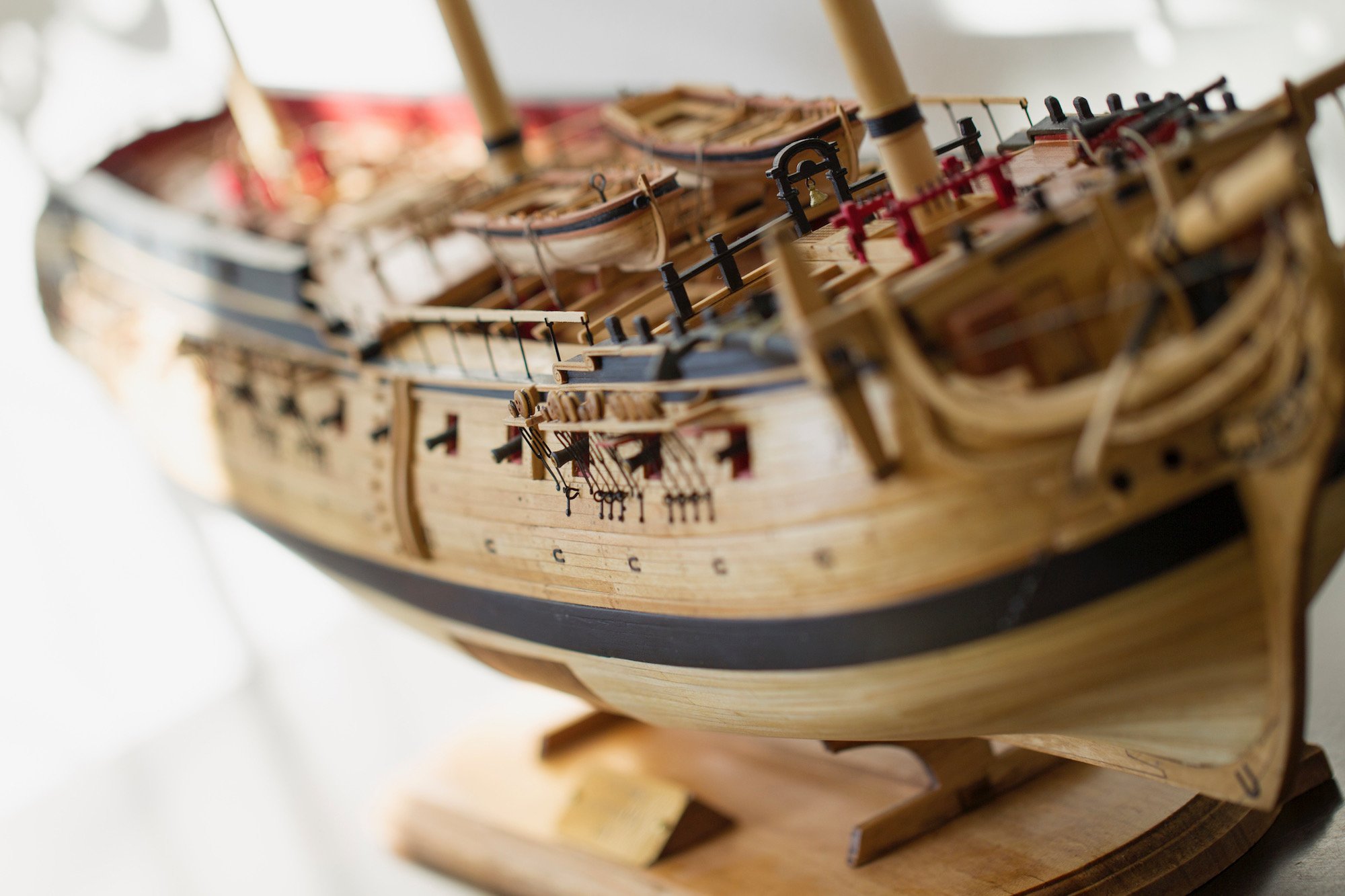
Once the Fo'c'sle has been constructed, the foredeck has been mounted to it, and the head beam is put in place, I was able to add both the bowsprit and foremast. Unlike later ships in which the bowsprit and foremast are mounted separately, the Santa Maria's bow masts are linked together. This made for a very tricky process. The technique involved putting the two masts in place while the foredeck was unattached. I then bound the two masts together at the proper angle at their base. The patience then kicked in when it was time to mount the foredeck while matching up where the masts enter the main deck. The final product with the head beam and windlass in place looked pretty good. It all makes me realize just how little space the sailors had to run around and actually sail the ship.
- 274 replies
-
- 2
-
-
- Santa Maria
- Artesania Latina
- (and 2 more)
-
To ease the tension of the rigging, the lines go through holes in the foredeck and around pulleys called reeving sheaves. To create these sheaves, I first drilled holes into the foredeck clinker planking. Then I created the pulley by cutting off the end of a dowel and grooving it. The ladders are created exactly how one would expect - each piece is cut then glued together. It takes a great deal of patience and persistence to glue the ladders with all of the "steps" even and secure. To ensure the ladders are held in place adequately, each ladder is fitted with a pin in the base. A corresponding hole is then drilled in the ship. This extra step dramatically increases the stability when the ladder is mounted between decks. Although some reference material shows only one set of steps from the poop deck, Xavier Pastor's reference shows two ladders. The final detail to the ladder is the chain guide running from the top stanchion to the bottom stanchion.
- 274 replies
-
- 1
-
-
- Santa Maria
- Artesania Latina
- (and 2 more)
-
Thanks Anja! Good to be back. :-) - Bug
-
Although most of the research I've read indicates that the Santa Maria was by all accounts a very basic vessel, many of the models being manufactured and displayed have an overwhelming amount of embellishments and accouterments common to Spanish vessels. However, many of these details were not evident until decades or even centuries later. I have chosen to keep this version of the Santa Maria realistic, but I am taking some small liberties that have not been well documented. For instance, I wanted to include more decorative windows on the rear of the captain's cabin that were likely present. I framed the windows with 2mm X 2mm strips cut and glued. Then I covered them with "glass" made from the plastic container that held some screws. I scored the glass carefully with an older, dull Xacto blade being careful not to pierce all the way through the glass. I then stained and mounted the windows to the rear of the captain's cabin trying my best to match the coloring as closely as possible on the outside, while maintaining a mahogany color on the inside of the cabin, a location which would most likely have been more decorative. A very tedious task that I had been putting off was the deck railings. Like the bow of the ship, the poop deck railing consists of stanchions, railings, then wooden slats. Each stanchion needs to be cut precisely then notched, rounded and sanded. Each stanchion mounted on the sides of the poop deck are the same absent the rounded top. More stanchions are then cut and prepared for the quarterdeck railings. Rather than just gluing each stanchion to the deck (which would be terribly unstable), I followed the same protocol as the bow and fitted the poles with a pin to hold them in place.
- 274 replies
-
- 1
-
-
- Santa Maria
- Artesania Latina
- (and 2 more)
-
Chair & Desk I had some pretty specific ideas in mind for the chair and desk and was happy I was able to pull off something close to what I envisioned. The chair is started from a strip of 1.5 X 3 mm walnut and modeled after a combination of some 1400s research and the chairs we have in our dining room. Our dining room chairs are Amish made from oak. The original walnut piece was sanded to fit the shape of the seat. The legs were sanded from a 2 mm diameter walnut dowel. This sanding was so delicate, that I went through several inches of the dowel just to get the four legs as well as the cross pieces. Finally, the back was sanded down to include a small curvature emulating an actual chair. I used my dremel tool with the smallest possible tip I could find to create the slats in the back. The entire chair was then left unstained, but coated in Tung oil to bring out the natural colors of the walnut. The desk is a really unique piece for me. Out of sheer coincidence, I was given a set of wooden pens. Each pen came in it's own case. The sides of the case were these beautiful little pieces of polished mahogany that fit absolutely perfectly with what I was trying to accomplish! The only drawback, they were extremely difficult to cut, sand, and polish. The legs of the desk were made from a 3mm diameter dowel that I inserted into my drill (same trick I often use) to create a make-shift lathe. I then used a variety of pin files to get the patter that I wanted. Once again, I went through many cases of the legs breaking off before I ended up with four good pieces. It was also very, very difficult to get four legs whose patterns looked close enough to one another to be acceptable. Finally, I sanded (600-1000 grit sandpaper) and polish all the pieces, stained the legs, and coated the entire combination with another coat of Tung oil. Chess Set: I am a huge fan of chess. In my home I have a collection of 14 different chess sets from 13 difference countries. I realize that actually have a chess set and table on board a ship the size of the Santa Maria is completely and utterly unrealistic. However, because I love the game, and it's not too much of a stretch to think the Ship's Captain would be a player, I decided to add the chess board. I'd also seen another builder create one out of card stock, and I admired the effort so much I had to give it a shot. The board is made from a soft piece of pine. Each set of squares is a mm wide, and the entire thing is boarded by 1.5 mm x 1.5 mm mahogany. Coloring the squares was obviously a huge challenge. I scored the wood at 1 mm intervals with a razor blade, then I used wood stain and a size 0 brush. Each drop of stain fell and spread within the square, but was successfully contained by the cuts in the wood! At first I tried to have some detail in the pieces, but that failed miserably. Instead I just distinguished them by size. I also realized that trying to have all 32 pieces was going to make it pretty crowded - so we'll have to consider it mid-game with a few pieces missing. Here are a couple of shots of the final pieces and how the desk will ultimately be arranged within the cabin. Finally for the cabin is a bed, at least one chest, a toilet facility and a couple of other small items.
- 274 replies
-
- 4
-
-
- Santa Maria
- Artesania Latina
- (and 2 more)
-
Pictures & Frames: Each picture was selected from the time period, but it's a complete guess on what a devout member of the church and essentially an employee of the monarchy would have brought along.The first frame is built with 2 X 2 mm strips of mahogany sanded down and mitered and the corners. I mounted the strips onto a piece of printer paper to stabilize them. I used a sharpie to darken the back and mask any irregularities since the margin for error here was so slim. I stained the frame a dark stain, then painted it with a thin layer of gold paint. This coloring ended up very similar to many of the frames I've seen over the years while living in Europe and visiting museums. This first picture is one of the many, many versions of Mary and child. The second frame is made from sapella with two layers of mitered pieces. The two layers gives it a little depth and gives the appearance of a slightly more elaborate piece. The final product is stained a red oak. Books: Three books are all made from balsa wood and a layer of cardstock with a printed coloring. The balsa wood is sanded to shape with pin files and 600 - 1000 grain sand paper. No matter how fine the sand paper is, the balsa wood is not going to be perfectly smooth. This is an added bonus in this situation and gives the appearance of texture for the book. The wood is then painted white and the edges are repeatedly scored with an x-acto knife to give the impression of several pages. For the open book - a red marker and some red highlights are added to give the overall impression that this book is a Bible, which would have most certainly been carried by Columbus. The Sword: The sword is based on some light research on what a typical 15th century Spanish blade may have looked like. The blade is made from a 1.5 x 3 mm piece of walnut. I chose walnut because I've had more success with the wood holding together while I sand it very small. Nonetheless, the sword still took a couple of tries before I managed a successful blade. Even still, the handled snapped at one point and I had to superglue it back together. The good news is, that was covered by the paint. The brass protective / decorative piece is made from a strip of brass. I had to sand the corners to get it to bend in the directions that I wanted. Once I had it successfully shaped, I added the knuckle shield. Gluing each of those pieces ended up being the biggest challenge in making the sword.
- 274 replies
-
- 1
-
-
- Santa Maria
- Artesania Latina
- (and 2 more)
-
You may remember, my initial desire to build the ship was instigated by my teenage daughters' lack of knowledge of the Santa Maria - which I found quite disconcerting. That's why, as I laid out in the previous post - a big part of my vision for this project was being able to see inside the captain's cabin and to have some items within that cabin that illustrate the time of the voyage of Columbus. Granted, there is quite a bit of editorializing and guessing when it comes to the items that I've started to build here. That's mostly because there is so little documentation regarding that voyage, and Columbus' own notes with regard to basic amenities are sparse at best. However, I did base the look of the cabin on actual items from the same time frame, and with a Spanish and sometimes Italian slant. First, I had to finish constructing the cabin itself: I started by cutting a sized template of two-layer thin plywood. I planked the inside with the same mahogany strips I used for the rest of the cabin. The outside of the cabin is stripped with the walnut planks used on the rest of the hull - which is important because I plan on using the same stain pattern and color. The door itself it cut, then fitted with brass hinges pinned down with brass pins. The pins have been cut to less than a millimeter, but the head is still showing. Then hinges and door are then aged with blackening patina. Also notice that there is crowning all around the inside and outside of the cabin wall. Finally, the door and hinges are fitted to the wall. The hinges on the wall and doorframe needed to be inset slightly to allow the door to fit smoothly. The door is mounted with two small pins that are inserted into pre-drilled holes into the frame. Once the cabin was pieced together, I was able to draw out a plan of what I wanted inside. I'll touch on each item individually to illustrate how it was made.
- 274 replies
-
- 1
-
-
- Santa Maria
- Artesania Latina
- (and 2 more)
-
A big part of this build for me is the ability to see the Captain's cabin and the accouterments that are inside. I've mulled over how I wanted to accomplish that tricky feat, and have decided to come up with a hinged poop deck. I want to be able to open the deck and see the cabin, but still have as much accuracy as possible regarding the rigging along the stern and transom. I started by carefully measuring the poop deck and then cutting the outline of the section that will hinge upward. Although they are obviously a complete flight of fancy, I wanted the hinges themselves to be effective, but to also remain representative of the time period. My concept was to attach small dowels to the underside of the deck, then mount them to the deck edges with brass loops and pins. The brass strips were drilled with the small bit then aligned with the dowel and the deck. The thickness of the deck became and issue and needed to be trimmed so that when the deck opens it is not obstructed. The dowels and hinges also needed to be separated enough from the edges so that they too were not obstructed. After the pieces were put together, the entire deck was then dry mounted to the stern of the ship. It was during this time that I discovered that somewhere along the line my measurements were off! The Port side of the stern of the ship was 3mm longer than the starboard side! My guess is that at some point during cutting and measuring I didn't take into account the thickness of the outside planking. At any rate, not the deck did not fit properly on the stern of the ship and needed to be repaired. My plan was to cut off a portion of the bulwarks where the lines intersected, then attach a new piece that was the additional 3mm longer. My hope was the if I made the cuts in the right place I could come very close to patching and staining the area to get it to look very close to the existing bulwarks. Since the area I needed to replace was very thin, I suspected it wouldn't hold properly with just glue. I drilled and inserted metal pins into the bulwark on which to mount the new piece. After gluing and mounting, I re-paneled the inside planks with mahogany, then the outside with walnut and stain. I then re-positioned the vertical strake so it evened up with the starboard side of the ship. Finally, I soaked, steamed, and molded the walnut railings from 1.5 X 4mm strips and mounted them as well. Ultimately, the repair turned out well and I think the mistake will not be very noticeable in the finished product.
- 274 replies
-
- 1
-
-
- Santa Maria
- Artesania Latina
- (and 2 more)
-
After mounting the foredeck, and getting pretty much all I could out of the main deck and working the hull, I decided it was time to finally mount the second deck. I sanded around the edges to get it to fit as smoothly as possible along the bulwarks of the ship. There's a small gap between the deck and the bulwarks, but that will be covered with a very thin strip mounted where the deck meets the rest of the ship. As you can see, it took a little bit of creativity to hold the deck in place while the glue dries. It's pretty common practice for me to use whatever is available to lodge, lean, mount, or clamp parts together while they dry in place. I also carved and sanded my own version of deck mounts to the port and starboard sides of the ship, once again based on the illustrations from my reference materials. Another major distinguishing difference between this kit and many of the reference materials for the Santa Maria is the existence of a "head beam" at the bow of the ship. According to the famous "Mataro Model" studied at the Rotterdam Maritime Museum, a beam at the bow was in Spanish vessels of the time to help hold the anchor(s). The Mataro model is the only actual model in existence that closely represents Spanish vessels of the 12th and 13th century timeframe. Many of Xavier Pastor's references in the book to which I refer are taken from the Mataro model as well. For these reasons I decided to also include the head beam on my ship. It definitely creates a tight spacing issue at the bow of the ship, but I think increases the accuracy of the model by quite a bit! I took a 5mm X 5mm piece of walnut and soaked it overnight. Then I steamed and heated it to get a mild bend. It took a lot of patience and slow manipulations. I then drilled then sanded the square holes in the bow to accomodate the beam. I had to sand the holes at the same angle that the beam would sit, which essentially meant mitering the edges instead of just cutting them straight out. The hard work paid off with the beam in place and sitting snuggly. It took several gentle taps with the small hammer to get it in place without damaging the hull around it. I actually didn't even glue it in place because it fit so tightly.
- 274 replies
-
- 1
-
-
- Santa Maria
- Artesania Latina
- (and 2 more)
-
After aging the hull and piecing the keel together, I felt it was time to finally mount the ruddder. The first step was to prep the stern and the keel. First I measured where the brackets would line up and notched out those areas. Notice I also marked off where I would need to carve out a few areas. A uniquely shaped hole in just above the rudder holds the steering handle, or "tiller". Unlike later ships where a helmsman used a wheel attached to the rudder with ropes and pulleys, very early vessels had a more direct way of steering the ship - a very large tiller. At any rate, I first drilled out the outline of the tiller hole or "helm port", then delicately carved and sanded out the proper shape. The two holes to either side were used to tie off the rudder to the tiller and limit its movement. I then molded and cut small strips of brass where the "gudgeons" and "pintles" would match up. Essentially these are the hinges that allow the rudder to move freely back and forth. After they were mounted I aged them and used black touch up paint to fill in any gaps while letting a small amount of brass show through. I flirted with the idea of actually hinging the rudder to the rear of the keel and actually allow movement. It didn't take long to figure out that was a very difficult proposition so I relented to mounted the rudder stationary. I used pins inside the pintles to mount them to the keel and keep them aligned. Finally, I carved and mounted the tiller itself then attached the entire rudder to the keel at the stern.
- 274 replies
-
- 1
-
-
- Santa Maria
- Artesania Latina
- (and 2 more)
-
The windlass is a heavy duty crank that was used to lift and lower very heavy items, much like the capstain. The windlass however must most often specifically used to raise and lower the anchor(s) on most ships. Again, much like the capstain, the windlass provided in the Santa Maria's kit is less than impressive. A quick glance at Xavier Pastor's book gave me the guide I needed to create my own. I started with my own version of a poor man's laithe. I set a 10mm dowel into my trusty hand drill and began sanding it down. If this is something you end up trying, it's VERY important that you wear gloves and eye protection. The wood gets very, very hot while spinning, as do the files and sandpaper. Also, little bits of wood are constantly flying off with potentially harmful consequences for your eyes. This process is very slow and requires a lot of patiences. One mistake and your entire piece can be ruined. Take your time and file off a small amount at a time. Measure out each section with a fine tip black pen. The mark shows up as a line when the dowel is rotating. Shaving down the dowel on my 'laithe' took somewhere around two hours total. Each section then needed to be carved down to make the grooves for the windlass. The sides and rear pieces of the windlass are carved out and fitted. The piece in the middle is essentially a stopper. This allowed the windlass to be cranked in one direction withing spinning backward. The completed windlass is then stained and "aged" like the rest of the pieces. It will eventually be mounted near the bow of the ship and rigged to the anchors and headbeam. Update: So I wasn't completely thrilled with the windlass, specifically the rear mount for the little lever. So looked up a few more versions that reflect that time. First I squared off the holes on the ends for the levers and widened the base mounts on each side. Just looked too thin to me. Then I reworked the back side going with two independent posts instead of something attached to the windlass. It made more sense for the lever-lock to go in between those with a wooden dowel and cotter pin.
- 274 replies
-
- 2
-
-
- Santa Maria
- Artesania Latina
- (and 2 more)
-
The fo'c'sle, of 15th & 16th century Spanish Naos is very unique, sets them apart and makes them easily recognizable. However, it also creates a very insteresting challenge for this build. I started out using a thin cardboard template to measure out what I would need to build. That way I could trim as necessary. The problem I ran into was getting the template stiff enough to sit in position while I put it together and made adjustments. So I measured and created a wooden frame. I couldn't get the slope of the bow right. Especially since I'd already planked my cardboard templates with the thin veneer walnut. Trying to trim the top where the deck would sit and sanding the super thin veneer glued to the thick paper was impossible! The walnut just kept splintering off no matter how subtle my sandpaper was. I was getting super frustrated. So I re-thought my plan, and started over. I took the patterns that I'd already made, and used them to cut very thin plywood instead of cardboard. I took into account the errors in measurement I'd made before. That at least got me very close. My reformed idea was to cut the pieces, mount them, get everything to fit, THEN glue the clinker planks. That way I could use fingernail scissors to make adjustments at the tiny area where the deck and bow meet instead of sandpaper. I still needed to add a "brace" to get the pieces to stay in place and remain stable while I made final measurements and sanded the edges to fit perfectly. I used a piece of a sewing pin to lock that bar into place. I notched out the inside of the bulwarks for footing. This was necessary to get a nice even fit for the bottom of those thin walnut veneer pieces. Once the plywood was measured perfectly, adjusted, and mounted, I planked the entire thing with the walnut veneer. It's important to note that I used CA glue (super glue) here because clamping each piece wasn't very practical. Finally, I stained it all to match. This is what the foredeck will look like once mounted in place permanently. This piece is only sitting in position at this point because I still need to find a way to mount the foremast and bowsprit.
- 274 replies
-
- 1
-
-
- Santa Maria
- Artesania Latina
- (and 2 more)
-
It have been considering how to age the overall ship for quite some time, as I know I will only get one shot at doing it. My original option was to use a Tung oil on the natural walnut to bring out the natural grain of the wood. However, because the second planking veneer is SO thin, it only allows for a very small amount of sanding. As part of the planking process, very tiny remnants of glue show up on the hull - that very limited amount of sanding means it's nearly impossible to eliminate these remnants. Unfortunately, tung oil and stain bring out these otherwise invisible imperfections because the chemical reaction is different with the glue than the wood. Also, most of the unpainted images of ships I've seen from this era are much darker than the natural walnut used here. This is in part due to the "tarring" of the ships to make them waterproof. So, I finally chose to use a deep stain called "Kana" for the ship. I didn't want the stain to look "new", so I chose a several part process to age the vessel. I stained the ship, then sanded all the flats and edges until the stain seeped in but wasn't glossy. I then re-stained the ship again with another light coat and rubbed the excess off with the rubber gloves I was wearing. Finally, I coated the entire hull with a satin polyurethane for protection and to dull the final look. The result is the roughed up aged look of the vessel.
- 274 replies
-
- 1
-
-
- Santa Maria
- Artesania Latina
- (and 2 more)
-
"Wales" are the horizontal pieces of lumber along the hull that both strengthen the ship and provides it's "lines". Ship captains and sailors would often refer to a ship's lines when determining how she looked or how swift she might be while under sail. The "futtocks" are the vertical pieces of lumber that are perpendicular to the wales. They not only provide extra strengthening support, but are also the base for the futtock 'shrouds' or rigging lines that support the masts and ratlines. First I cut out the stern cabin windows.The comprehensive reference I am using for the Santa Maria ("The Ships of Columbus" by Xavier Pastor) says the Santa Maria was a "dull" looking ship with very few adornments. The book also shows the cabin windows as square. However, I have often seen Spanish ships of this era with these kinds of windows. So, in this case I took a little creative license with the shape of the windows. Later they will be bordered with either walnut of mahogany. I started with the outside framing of the stern and near the rails, then mounted the upper gunwales. Each one has to be perfectly positioned. I start with the port side, then measure starboard side to ensure the ship will be perfectly symmetrical. Since early on I restructured the hull of the ship to be a rounded tuck stern the wales are more difficult when they reach the rear of the vessel. I've aligned the lines of the cabin first to help keep the wales in relation to one another. Each wale is soaked then bent with the plank bender. The wale is then mounted on the ship. Notice the bow of the ship where I started experimenting with how I will stain/age the vessel (more on that below). After the wales are mounted and glued, I covered the deck with painter's tape to avoid damage to it during the sanding/gluing process as well as the staining that will come later. The futtocks are created with strips of walnut that run perpendicular to the wales. This provide a great amount of strength to the hull and bulwarks, especially in rough weather. I fashioned a small sandpaper file the exact size of the 1.5mm x 3mm strips to facilitate the process. The placement of both the wales and the futtocks follows Pastor's reference of the 1992 replica that I believe is the closest representation of the ship as a Nao. Each futtock is measured, then the wales are sanded down to make room. Each futtock is a two part process - the first is the 1.5mm thick plank placed where the futtocks belong. The second part is an additional 3mm x 3mm strip added on top of the first plank. This gives the futtock is thick presentation. The smaller futtocks toward the main deck and bow are an additional 1.5mm rather than 3mm as these futtocks were not as deep as the rear ones. After the second layers were added, each is trimmed with a carving tool so the edges match exactly. Since these areas are extremely difficult to sand, the carving tool needs to come as close as possible to matching the layers of the futtock. I don't want the fact that each futtock is two parts to be immediately visible when the ship is complete.
-
The process for planking the quarterdeck and the poopdeck is the same as planking the main deck. Each plank is trimmed on the sides with a black permanent marker to create the "tar" that kept the deck waterproof. After the deck planks are glued in place onto the false deck, then are trimmed and sanded. The main deck then needs "camber". This is the roll in the deck that allows the water to flow to each side then drain out of small holes called "scuppers". I created the camber of the main deck by soaking it, then carefully bending it around a plank of wood. Keep in mind that this camber is much more severe than the deck will be on the ship, but it will flatten a bit when put in place. The poop deck is planked in the same manner. Then the 'trenails' are drilled and the butt planks are cut. The deck is then bordered with walnut trim. This deck (the highest deck and furthest astern) will be removable to see inside the captain's cabin. I've added a "railing" to the rear half of the ship. This will facilitate mounting the quarterdeck. The The main deck is then trimmed with a stringer that runs along the port and starboard to link the deck with the bulwarks. The "scuppers" mentioned above will be cut along this stringer. Then, stanchions are mounted along the bulwarks. These vertical strips of wood strengthen the ship's hull. I've created these stanchions out of mahogony instead of the walnut that the rest of the parts are made of. This will give the deck a little bit of contrast.
- 274 replies
-
- 2
-
-
- Santa Maria
- Artesania Latina
- (and 2 more)
-
The capstan, or capstan wench, is a vertical-axled rotating machine used to apply force to ropes, cables, and hawsers. The principle is similar to that of the windlass, which is a horizontal version mostly used to raise and lower the anchors. In its earliest form, the capstan consisted of a timber mounted vertically through a vessel's structure which was free to rotate. See the illustratoin on the left. Levers, known as bars, were inserted through holes at the top of the timber and used to turn the capstan. A rope wrapped several turns around the drum was thus hauled upon. The two pictures above compare an actual capstan from a 15th century Nao vessel, while the right picture is what was supplied in the kit. I actually tried (and failed at) several different methods before coming up with this version of the capstain. I ended up cutting very small (5mm) pieces from some leftover sapella wood. I then cut and trimmed a 5mm dowel and sanded it. I glued the sapella pieces to the dowel. For the top of the capstain, I trimed and used the original piece from the kit because I preferred the shape. I cut and sanded to small discs of different sizes to separate the parts of the capstan and glued them all together. I needed to use different types of wood to formuate the pieces, and they all ended up being different colors and grains. So I painted the entire capstain and stained it to even out the colors. Finally, the bars are brass dipped in the patina to color it.Similar to the forward main grate, the stern main grate needed to be constructed. The kit I'm using didn't even have a main grate toward the stern, pobably because it's not easily seen while on display. I need to get all of these main deck fixtures completed before I can mount the quarterdeck. You may recall I fashioned the forward deck with locked doors but I will make the rear grate more traditional cross-hatch. I used the same process as the forward hatch, putting together eight small walnut pieces miter'd at the corners. Then I cut and mounted the cross hatch wood. Finally, staining the entire piece.
- 274 replies
-
- 2
-
-
- Santa Maria
- Artesania Latina
- (and 2 more)
-
Most "real" ships only have a single layer of planking of course. But several kits provide for a second layer. This gives modellers an opportunity to clean up any mistakes that are made planking the ship by using a second, thin layer of veneer. I've actually found the thin veneer to be even more difficult to lay down than just single planking a ship. Nonetheless - here is the second layer planking process for our Santa Maria. I started with planking the stern and captain's cabin. This helped ensure that even though the deck and lines of the ship "swoop", the planking will still be even and parallel. Just like the first layer of planking, each piece of wood needs to be measured, dry fit, and cut to fit into place. However, because the second layer of planking is so thin, it doesn't need to be soaked before it is bent. The down side is - because the planks are so thin, there is no margin for error because you can only perform a light sanding to even out any mistakes. The front end of the planks must be measured and cut to fit the lines of the keel at the bow. There will be some sanding involved of course, but it will be very little. Anything more than a half milimeter will be very apparent on the final product. Each plank it glued, then held into place with clamps until it dries. The thin planking does allow for the choice of "Super" glue instead of water based wood glue. This makes the process quicker, but of course means there is no room for error. Once a plank is in place, adjustments cannot be made because of the instant bond. When the natural placement of the wood plank does not match the lines of the ship, small gaps appear between the planks. This is a normal part of planking. In these cases, the gaps/planks would not come to a point because that doesn't allow for room to "nail" down the plank and makes the overall hull very weak. Instead, "stealer" planks were used to fill in those gaps. The stealer plank was never narrower than half of it's full width. The final plank on the port side of the ship. It is also a type of "stealer" plank, and is measured to fill in the last remaining gap. As with other stealer planks, this final piece is made wide enough to allow for a proper fit. When all the planks are in place, the hull is sanded. As mentioned before, only very little sanding can be done. In this case I peformed a very light overhaul with 400 grit paper, then sanded a second time with 600 grit paper. This isn't as smooth as it could be, but will allow for a weathered look when the hull is finally stained. Now the hull is ready to add waterlines, wales and futtock riders...
- 274 replies
-
- 2
-
-
- Santa Maria
- Artesania Latina
- (and 2 more)
-
Attached to the rear keel with hinges, the rudder seems like a simple part to create. However, getting the rudder to look proper based on the time frame is a little more difficult than it looks. I referenced both Pastor's book on Columbus' ships as well as Mondfeld's book on historic ships to model my rudder for the Santa Maria. Early rudders were made from two pieces of wood wrapped together and attached with metal strips. There is a main part of the rudder and a smaller strip called the "bearding". More strips then make up the hinges. It is also important for the angle of the bearding strip to match the angle of the ship's keel so it all fits together and works smoothely. Brass strips are carefully cut and glued into place to attach the bearding to the rudder. I also added glue, to ensure that the pieces fit properly together. More brass strips are then cut and bent into the shape of the hinges. The angles and bends must be exactly right to make a good fit. After all the strips are in place, holes are very carefully drilled for the nails / rivets. This is a very delicate process and I went through 3 broken drill bits getting these holes in place. Nales / rivets are trimmed so only the heads are available with about 1 mm of nail so they don't go all the way through the rudder. They are nailed and glued in place. After everything is constructed, the entire rudder is blackened using the chemical oxidation process. I also touched up the area with flat black paint. The wood is treated with dark stain then coated with tung oil and polyurethane for protection.
- 274 replies
-
- 2
-
-
- Santa Maria
- Artesania Latina
- (and 2 more)
-
In actual vessels of the time, the bulwarks were created from the bulkheads and planking all the way up the sides of the hull. However, for most ship kits, this is simulated with molded pieces of plywood that are then planked over. This drastically eases the process of inserting cannon ports and other openings. Unforunately, the wood used for the bulwarks on this kit is very poor. Most pieces of wood can be soaked and bent, then dried to the desired shape. As soon as the bulwarks here were soaked and formed, they split wide open. Since this meant I needed to recut the buwarks, I took the opportunity to recut them based on the lines in Pastor's book and make them more accurate. The picture on the top left is the kit's directions - it shows the buwark including the clinker foredeck base and just covered with planking. This is a simplified but inaccurate way of building the foredeck mount. The picture on the top right show's the kits' pre-cut bulwark which I tossed out. You can see it includes a higher raised bow for the foredeck. The picture on the bottom shows the estimated lines of the ship according to the Captain's notes and Pastor's book. When I recut the bulwarks, I removed the raised bow area and will build the foredeck mount as a separate piece. I also took the opportunity to increase the height of the aft area, specifically the Captain's cabin. Not only is this consistent with Pastor's guidelines, but it also gives me more room to outfit the cabin when the time comes. The larger cabin will also provide for larger windows in the stern and the sides of the aft. Since the aft and the cabin are larger, the pre-fab pieces of the transom (rear deck walls of the ship) that came with the kit also won't fit properly. First I used a piece of paper to create a template, then cut out a matching piece of plywood. I soaked the plywood and wrapped it to let it dry until the radius matched the radius of the ship's transom. I also needed to increase the size of the rear cabin since I increased the overall cabin size. A extra 5 millimeters did the trick. It was difficult mounting and glueing the transom because the edges of all the pieces were so thin. I added an extra 2mm x 2mm piece of walnut to the corners to give the edges something to hold onto. After the glue dries I added filler and sanded both the inside and outside edges and readied them for planking. The inside of the bulwarks are planked with walnut veneer. Since my plan is to make the Captain's cabin visible, I took a little detour from the instructions to enhance that. Although most cabins from ships of the time are white, this is where I decided to deviate from accuracy. I planked what will be the cabin area with mahogony veneer instead. I think this will enhance the overall look of the cabin after the furniture and accessories are included. After the planking was complete, the entire area was sanded with 600 grit sandpaper, then stained with a dark ebony stain. After the stain, the entire ship is coated with tung oil to bring out the color and grain as well as protect the wood.
- 274 replies
-
- 2
-
-
- Santa Maria
- Artesania Latina
- (and 2 more)
-
Following the same pattern and methodology as the foredeck, I started planking the main deck. It's much easier to plank a deck before it is attached to the hull, so I cut an additional false deck to plank. The original deck that came with the kit was attached to the hull to stabilize the bulkheads and the hull. Planking starts by measuring down the centerline of the deck splitting it into two equal halves. The deck is then planked from the center outward by measuring and gluing each plank. Deck planks for ships were also "caulked" with tar-like material between each board. This kept the deck watertight. To simulate this effect, I lined each plank with a black sharpie. It's very important to make sure that each plank is exactly parallel to the center and pressed together as tightly as possible to the other planks. To achieve these "closeness" I glued each piece, clamped it at the ends, then used an additional scrap piece of wood to press the planks together and then clamped that down as well. Planking is an extremely tedious process as each piece has to be indivually "caulked" with the sharpie, measured, cut, then glued and placed. The next piece cannot be placed until the previous piece is comletely dry or the builder runs the risk of the entire decking being pushed out of alignment. An important aspect of accuracy is simulating the "butt pattern" for the deck. That is the pattern in which each board is placed and "trenailed" (or nailed) into place. These methods varied greatly depending upon the time period and country of origin from which the ship was built. Since (as mentioned several times) there were no detailed records of how the Santa Maria was built, I had to use the mostly likely butt-pattern based on available research outlined above. There are a couple of options to achieve this effect when planking. one can either cut the planks to the length desired then glue them down, or one can glue each plank in it's full length then simulate the butts. Because of how thin these planks were, I chose the latter. (Note: With my prevous build The San Juan Nepomuceno I chose the former method and cut each plank to length) After the planks were laid, I gave the deck a very light sanding. Part of the difficulting of planking with the super thin strips like this is you're very limited with how much sanding you can perform. I then marked the butt pattern with a .5mm mechanical pencil. "Trenails" were small wooden dowels used to "nail" down the deck. To simulate these trenails I followed the same procedure as with the Foredeck and 'drilled' the holes with the .5mm mechanical pencil. Each hole is precisely marked This deck has 1,388 individually "drilled" trenails. After the butt-pattern and trenails are marked, I once again used the same method as the foredeck to achieve the desired color. The deck was most likely oak. To achieve a aged oak color, I gave the deck a very light coat of diluted "cherry" stain. Then I went over the top of that with a more substantial coat of "weathered oak" stain. Finally, I mounted the deck on the hull and am ready for the bulwarks.
- 274 replies
-
- 2
-
-
- Santa Maria
- Artesania Latina
- (and 2 more)
-
I began work on the hatch cover for the main deck. I started with an excess piece of plywood cut into a square. This gave me some stability for the initial framing. Without the plywood, it's very easy for the frame to become out of squre while trying to glue the corners together. However... because the plywood adds an extra half milimeter to the bottom, it won't sit flush on the deck. Therefore after the hatch is completed, the plywood will need to be sanded completely off. The edges are but at perfect 45 degree angles using a mitre saw. After the initial framing is made with 3mm pieces of walnut, I added a second layer of frame using the same 3mm pieces but lined up on their SIDE against the first frame. After the edges are sanded and rounded a bit, it gives the entire hatch a nice three dimensional look. The hatch "doors" are created using 5mm strips of walnut cut to size. I've used three on each side, then separated the doors with a narrower 2 mm strip. This will give a good impression where the doors come together. Since it's terribly difficult to keep something so thin but wide stable, I first glued each of the doors using three strips of walnut. Then I glue and clamp the two doors to the center piece and keep it all stable by laying flat piece of excess wood along the top and clamping that also. After it dries, the doors are sanded smooth and a "notch" it filed down the center to give the impression where the doors come together. Ultimately, the details are added. After trying to cut the hinges from brass proved too difficult, I instead used thick, black construction paper panted over with matte black. Holes are drilled and nails added and blackened. The handles are small brass eyelets also blackened. Finally, Columbus' inventory for the Nina actually shows a chain and lock for the hold, so I thought it perfectly conceivable that the same would be included on the Santa Maria. The small brass chain is blackened and the lock created from a folded strip of brass and a half brass ring. Then a small hole is drilled simulating the keyhole.
- 274 replies
-
- 6
-
-
- Santa Maria
- Artesania Latina
- (and 2 more)
-
Because planking the deck is such a tedious process (an update on planking the main deck is forthcoming), I divide my time between cutting, laying and glueing each plank, with constructing smaller details for the rest of the ship. My intention is to make the poop deck either removable, or raise-able to see what inside Christopher Columbus' cabin may have looked like. So I began fabricating items that my appear in that cabin. The first item is a candle on a candlestick. To achieve this, i took a 3 mm wooden dowel made of walnut and slowly lathed it by hand with sandpaper and a pin file. Most folks use either basswood or boxwood for carving, however I chose walnut for these pieces. Although walnut is more difficult to carve, it is also more dense and I believe and withstand smaller incisions and carvings and still stand the test of time. The next piece was a minature musket from the time period. I started with a 5mm wide pice of walnut and carved out the basic shape of the weapon. I trimmed small pieces of brass for the bands, and used a small but thick brass wire or cylinder for the barrel. The trigger and hammer are made from common wire. Once constructed, I dipped the entire piece into the blackening solution (same as the anchor) which turned the brass to a blackened weathered state, but also affected the would in a positive way. Next I attempted to make a captain's telescope using two different diameters of brass tubing, and a flat piece of brass rolled up. I cut the brass tubing and simply stacked the pieces on top of each other. However, because the glue wouldn't stabilize the pieces enough, I drilled small holes and inserted pieces of a sewing pin. The pin served to stabilize the pieces helping the glue hold. Because the end pieces was wrapped brass, it automatically gave the end of the telescope the look of a glass lens.
- 274 replies
-
- 1
-
-
- Santa Maria
- Artesania Latina
- (and 2 more)
-
The small details and "deck fixtures" can make or break the way a ship looks when on display. I often take a break from the 'heavy lifting' - things like planking and sanding - to work on these smaller details. Naturally one must be careful with regard to accuracy, especially for those items that stand out. For instance, the anchor is an easily visible item that can either add a lot, to take away a lot... The anchor supplied with the Santa Maria kit is a simple die cast molded item which looks pretty cheesy with metal stocks. The only option would be to paint them, which obviously that won't do - so I began recreating the anchor based on anchors of the time. I started by gluing two pieces of walnut together to create the stock, then breaking off the shank/fluke from the forelock (where the ring goes). After the shank dried, I didn't feel like it would be stable if I drilled a hole through the entire stock, so I decided to simulate the mount. Instead, I notched out an area in the bottom to fit the main portion of the anchor. I also notched out areas that will fit the bronze strips that hold the stock together. The bronze strips are cut, and carefully bent around the stock. I used super glue to hold them in place, then filed and sanded them down to make them look as seemless as possible. To create the bolts in the stock, I pre-drilled tiny holes into the sides, then clipped off the heads of pin nails and put them in. After they were nailed in, I tapped them repeatedly with a brass head hmmer to get them as flush as possible while still having them appear 'rounded'. To mount the anchor itself, I drilled a small hole in the top, and glued the end of a sewing pin into the end of the shank. Another small hole was drilled in the stock to fit the shank as well as the forelock. After the anchor is mounted and the glue dried, the entire anchor is dipped in a special solution that creates a chemical reaction turning the brass portion black. I chose to leave the anchor in the solution long enough that some of that reaction bleeds into the wood creating an older "weathered" look to the anchor. The finished anchor will be one of two that are mounted on the sides of the Santa Maria and winched up and down by the "windlass".
- 274 replies
-
- 4
-
-
- Santa Maria
- Artesania Latina
- (and 2 more)