HOLIDAY DONATION DRIVE - SUPPORT MSW - DO YOUR PART TO KEEP THIS GREAT FORUM GOING! (Only 13 donations so far - C'mon guys!)
×

Moonbug
-
Posts
1,028 -
Joined
-
Last visited
Content Type
Profiles
Forums
Gallery
Events
Everything posted by Moonbug
-
 Nice work. Very interesting treatment of the cabin, very cool. - Bug
 -
Hm.... can't believe I've never stained first then drilled and re-stained. That would sure cut down on the amount of "missed glue discoloration" of which John speaks! - Bug
- 2,191 replies
-
- 1
-

-
- confederacy
- Model Shipways
- (and 1 more)
-
Can't wait to see photos of the repair. I snapped the top off the mizzen of my San Juan during that build. It's remarkable how many of us have snapped a mast or yanked rigging out of whack despite how careful and precise we all are! Only takes that half second of inattenion... ... often followed by a flurry of colorful vocabulary, a period of slow methodical breathing (and maybe a tear), then finally a plan for reconstruction. Hey... at least you didn't have to pull it off at sea. - Bug
-
Thanks for the comments everyone! No problem Sjors! Must be for the Aggy right, I'm sure you've already got the indoor plumbing all laid out for Ildefonso Right? ;-) Marktime - Thanks for the comments and the information, that's fantastic. I only had a little information and made guesses from there based on some of the famous Russian models. I had not heard of that book, I'm definitely going to go out and try to track it down. - Bug
- 274 replies
-
- 1
-
-
- Santa Maria
- Artesania Latina
- (and 2 more)
-
Nice work. Was the red design already on the sail in your kit, or did you add that? - Bug
-
Nice patient work. Let the sanding begin! - Bug
-
There are a few different methods to planking, that's for sure. Personally, I don't think I'm particularly good at it, so I always refer to other folks'. - Bug
-
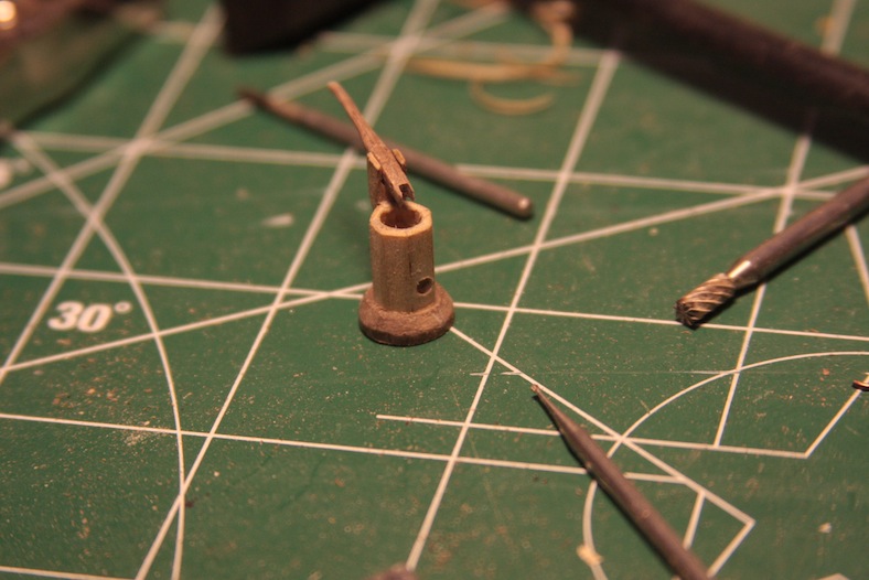
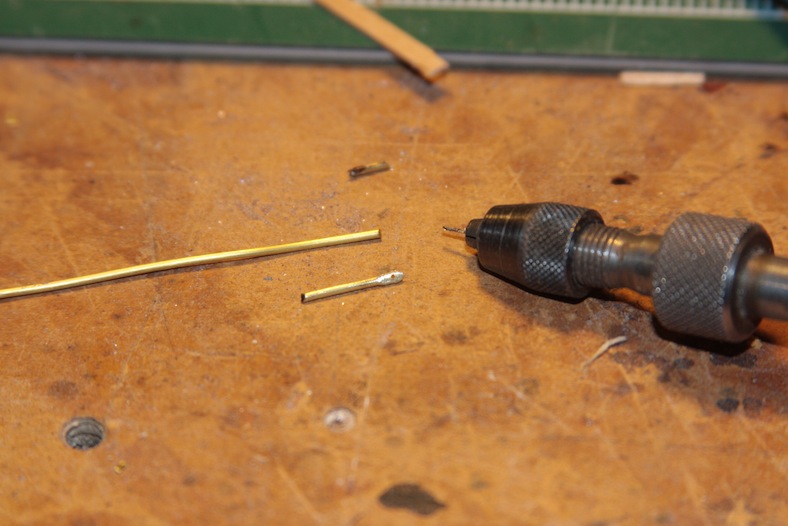
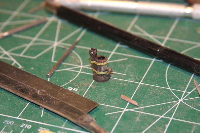
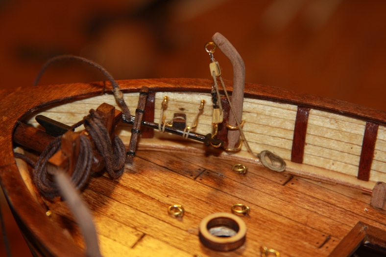
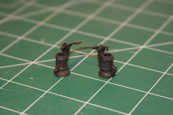
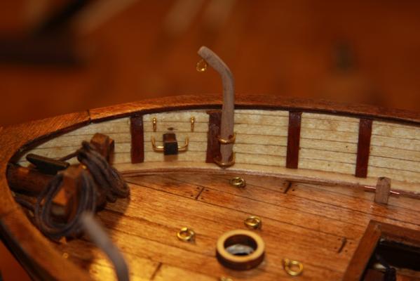
The handle of the pump is created from two strips of 2mm x 2mm square walnut sanded and etched out. They are based in 3mm x 3mm square walnut strips sanded to fit the side of the pump. The pieces all put together initially and then stained. The pump mechanism and the strips around the pump are made from a scrap brass dowel and scrap brass flattened pieces. I flatten the end of the brass dowel out by putting it between the flat areas of a pair of pliers and striking it with a hammer. All of the strips, the handle, and the pump mechanism are attached using a touch of glue, and then firmly attached using pins with the heads sanded down. Finally the pumps are re-stained, and the brass pieces are given a layer of patina.


- 274 replies
-
- 11
-
-
- Santa Maria
- Artesania Latina
- (and 2 more)
-
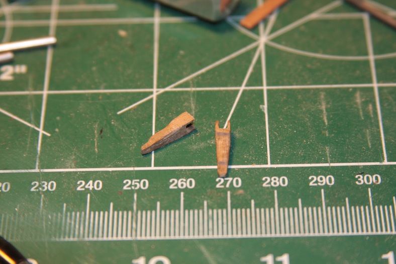
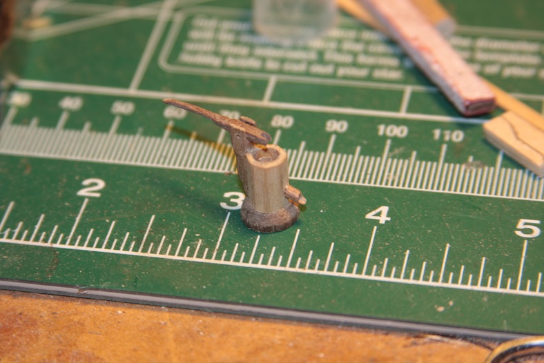
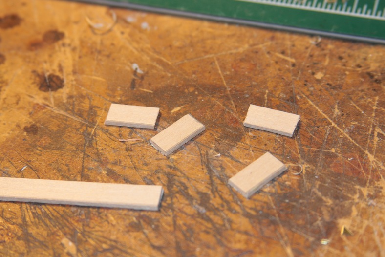
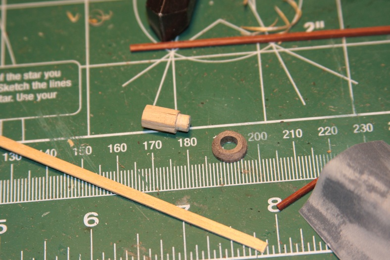
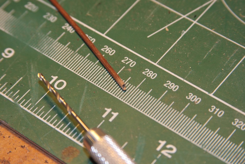
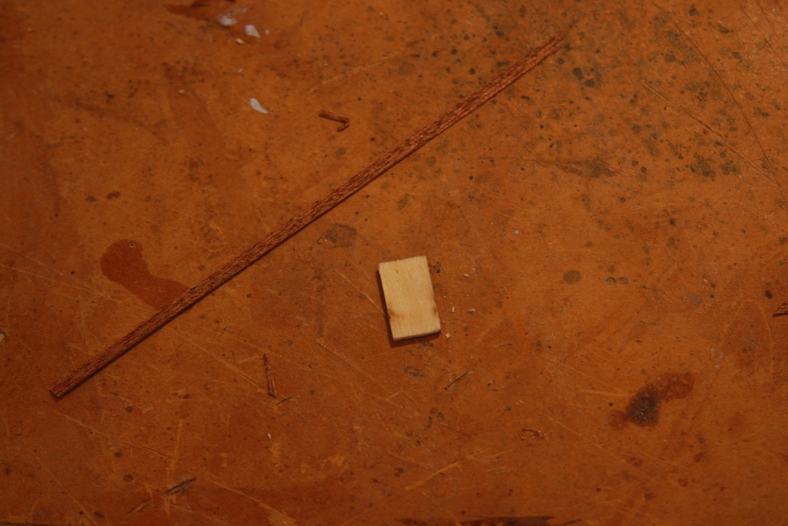
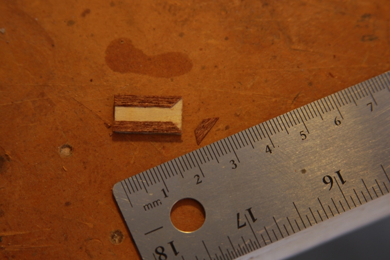
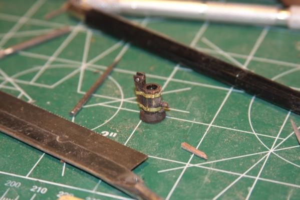
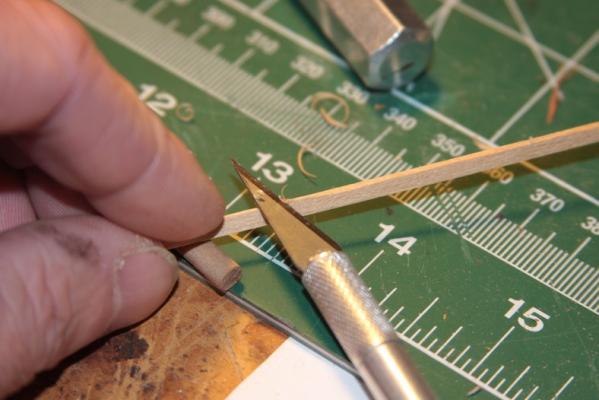
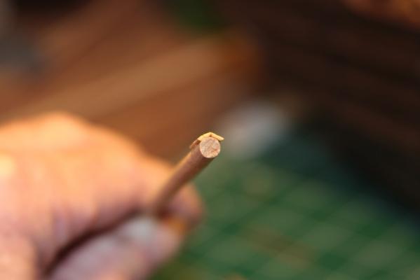
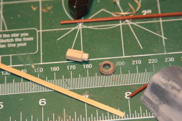
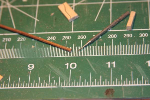
Although the Xavier Pastor book I have been continually referencing lists the Santa Maria as most likely having a single turn-crank water pump, every other reference I've seen has shown a more traditional pump-handle style water pump. Often times there are two, as in later ships. When it comes down to it - I think the pump-style handle looks better, so I went with that. To build my water pump I started with a 5mm diameter dowel and thin basswood strips. I trimmed the sides of the basswood strips at a 45 degree angle so they would fit together mitre'd nice and snug. I then cut them at 15mm lengths and glued them around the dowel to create the base of the pump. I went with this idea to create a solid base that wouldn't collapse when I started working on it. I then hollow out the base of the pump with a drill. The base is made from a 10mm dowel of walnut with the center drilled out at 5mm to accept the base of the water pump. Of course the sides of the base are sanded and beveled. The spout of the pump is a 2mm dowel of walnut with the end drilled out hollow first with a 1mm hand bit, then with a 1mm etching bit for a dremel at low speed.


- 274 replies
-
- 1
-
-
- Santa Maria
- Artesania Latina
- (and 2 more)
-
I'll echo what Keith said about the instructions. Sometimes I refer back to them to make sure there isn't some little cleat or something that I've missed, but for the most part research, MSW and other builds here end up being my instructions. I also ended up cutting a new rudder and stern post. Oh - and to echo Keith (again) - planking the inside of the bulwarks after they are fitted does make a huge difference. - Bug
- 114 replies
-
- 1
-
-
- swift
- artesania latina
- (and 1 more)
-
Thanks Peter and Eamonn for checking out my build. I very much appreciate the comments! - Bug
-
Hehe... You guys said "time line".... ;-) Don't think I've ever had a time line pan out as planned! Good thing it's all about the process and not the finish line. Nice smooth work Adrieke! -Bug
-
I wish I had better advice, but I had a very difficult time matching the hull to the keel. What I ended up doing was notching out the hull and thinning out the keel. That wasn't a correct answer though, more of a compromise fix at the time. I would just recommended dry fitting it and trying to line it up as cleanly as possibly. You probably won't start thinning until area two. Just remember you can always take away easier than filling. Bug
-
Nice work Russ. Good to catch up on your build(s) again. - Bug
-
Kostas! Glad you re-created your SJN build here. I enjoyed following your build while I was constructing my San Juan so it's glad to see your progress again. Very clean, nice work! - Bug
-
Pictures came through fine. Nice patient work, looks great. - Bug
-
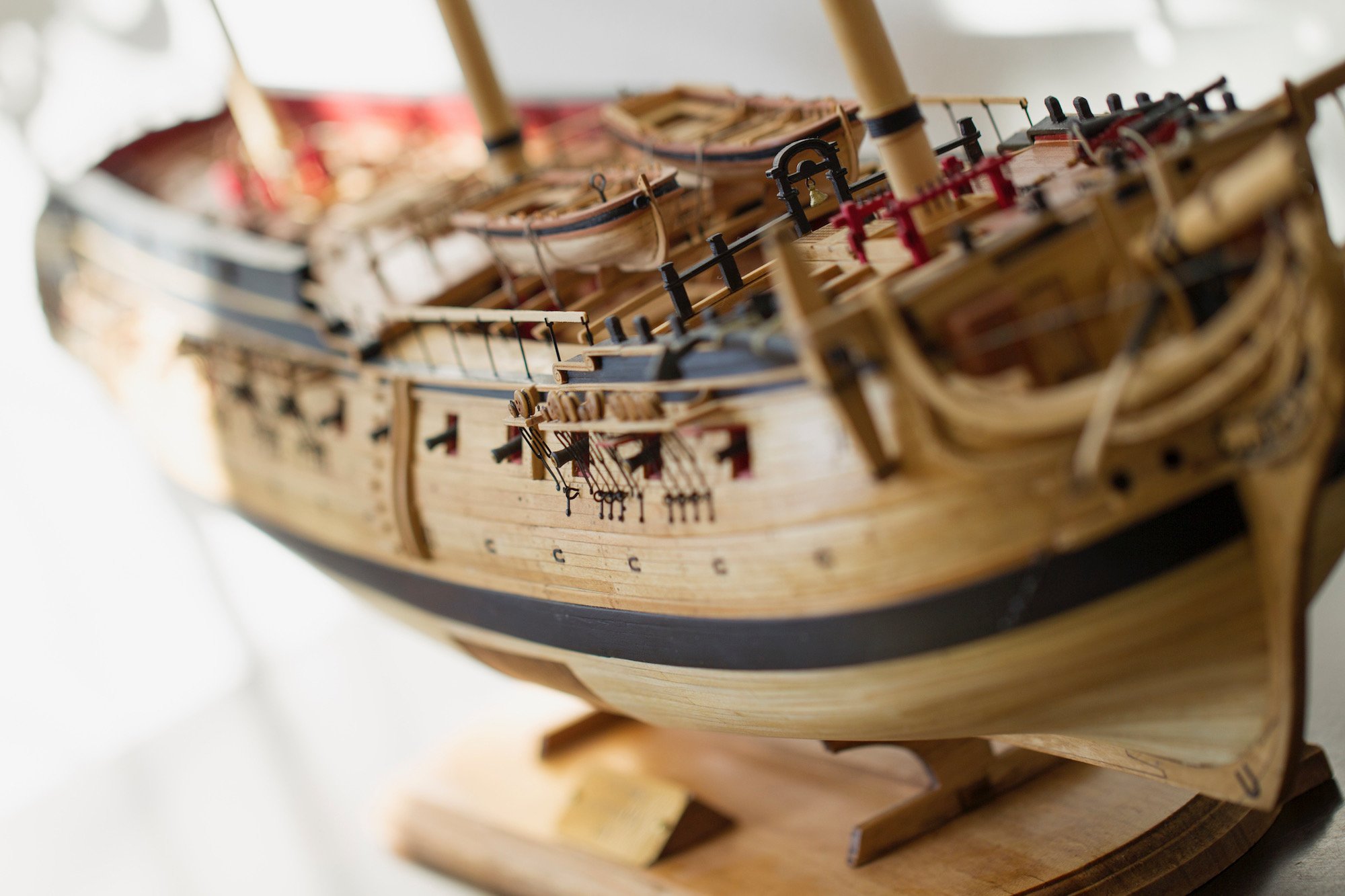
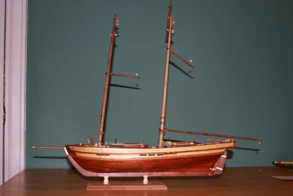
Some shots of details including the cabins and below decks. The rest of the finished shots can be found in the Swift gallery.
- 14 replies
-
- 4
-
-
- Swift
- Artesania Latina
- (and 1 more)
-
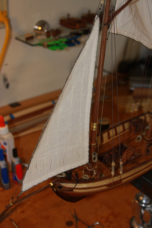
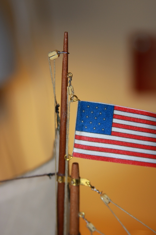
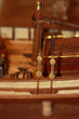
Some other rigging details. In particular the way the main sail was rigged - this rigging method was the result of quite a bit of research and was as close to authentic as I could find. The rigging directions in the kit were not specific and not particularly accurate.


- 14 replies
-
- 2
-
-
- Swift
- Artesania Latina
- (and 1 more)
-
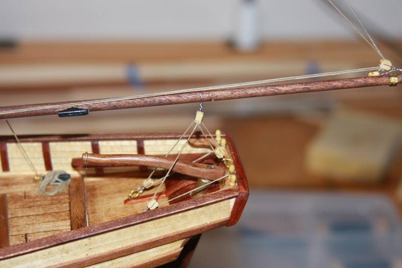
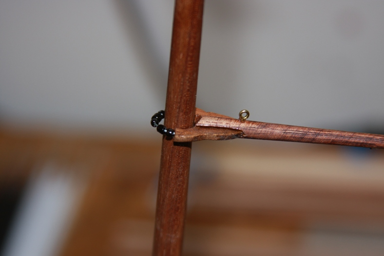
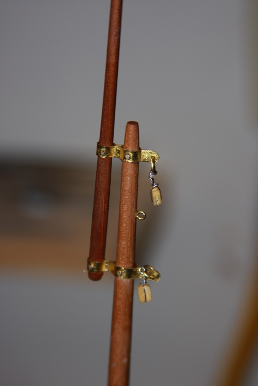
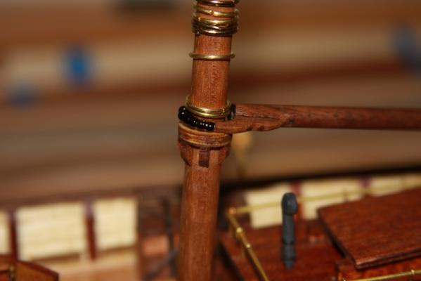
I discovered that this ship is lacking in certain details of course - one of them is an proper anchor mount and wench. These details were taken from Mastini's book as well as Baltimore pilot boat plans. These are some basic mast and rigging constructions.


- 14 replies
-
- 1
-
-
- Swift
- Artesania Latina
- (and 1 more)
-
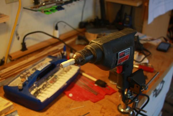
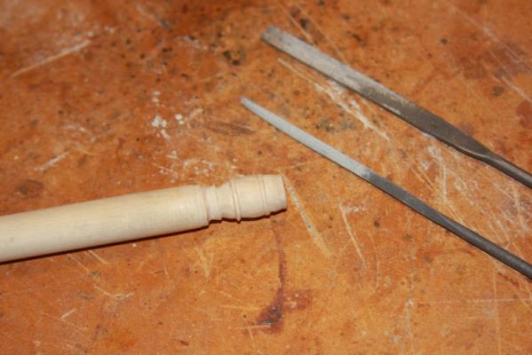
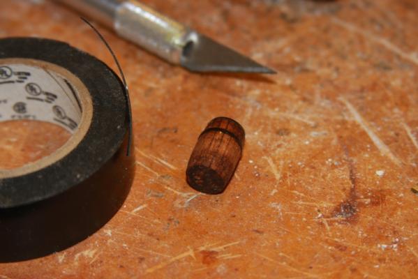
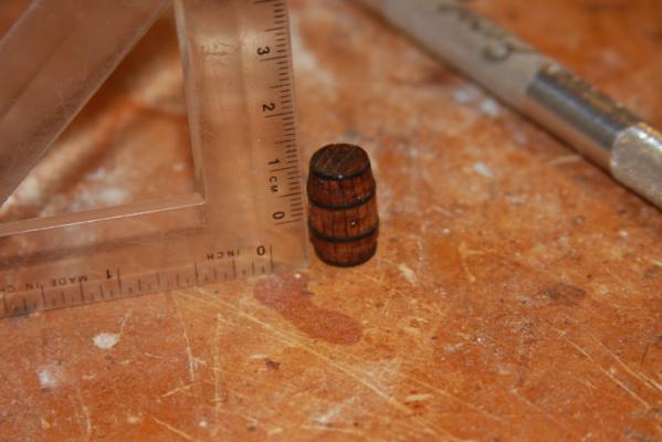
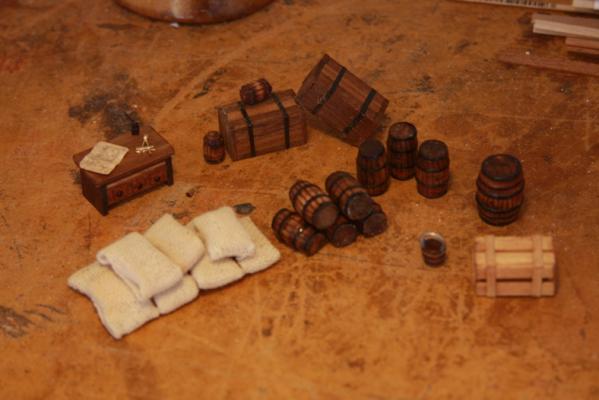
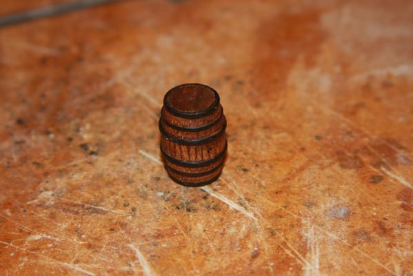
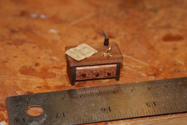
This kit is where I came up with my "fake lathe" method of creating barrels. I put a dowel into my drill and mount it in an anvil vice. When I tighten the vice on this particular drill, it somehow squeezes it just enough to keep the speed consistent. I then use both sandpaper and pin files to create the barrel shapes. I then use a miniature mitre saw to cut off the barrel and do the finishing sanding. I then score the barrels with one of the many X-acto blades where I've accidentally broken the tip off. I stain it, then I create the black barrel strips out of electrical tape that is super glued in place. The electrical tape actually works quite well as long as it is stretched the correct amount and held in place by hand until it dries completely. These are the barrels and packages that I created for below decks. The bags of wheat (or whatever they might be) are made from canvas pieces filled with balsa wood that is carved and sanded to the shape I want. Finally a captain's desk. The desk is taken directly from Mastini's book "Ship Modeling Simplified" The ink pot and pen are created from a walnut carving along with a tiny piece of paper. The sextant is soldered from pieces of brass as well as a couple of sewing pins.
- 14 replies
-
- 1
-
-
- Swift
- Artesania Latina
- (and 1 more)
-
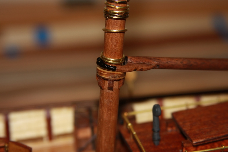
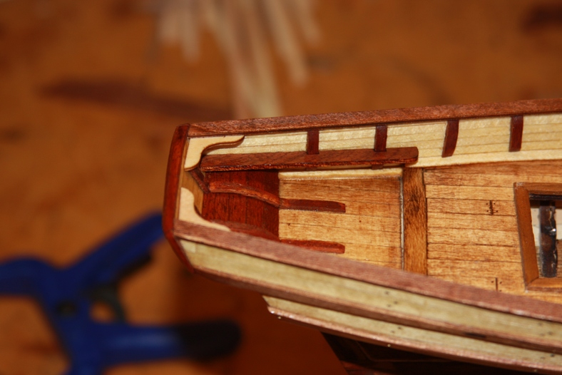
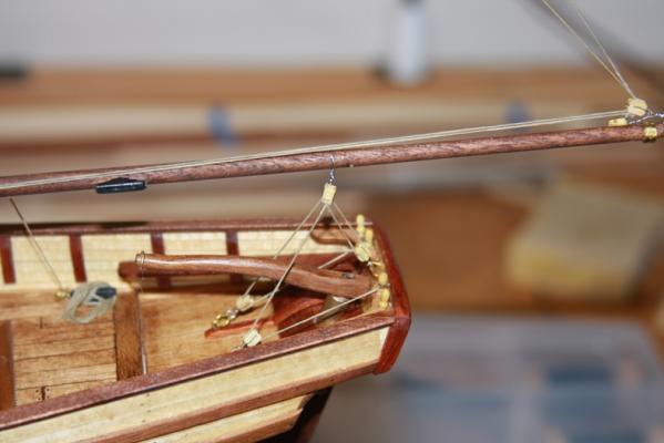
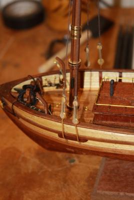
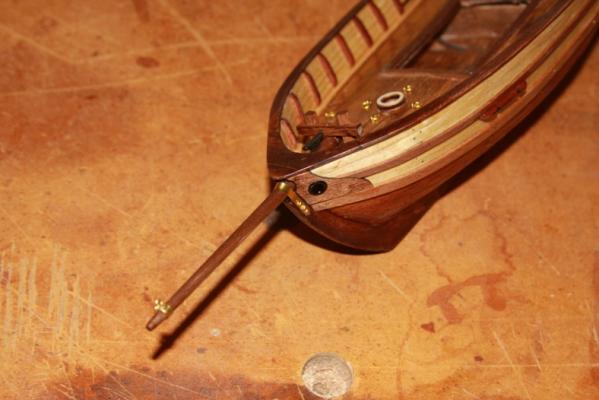
Mounting the bowsprit was a particular challenge. Because many of the pieces didn't quite line up, I needed to cut a new piece to fit the bow of the ship and re-create the front railing.
- 14 replies
-
- 1
-
-
- Swift
- Artesania Latina
- (and 1 more)
-
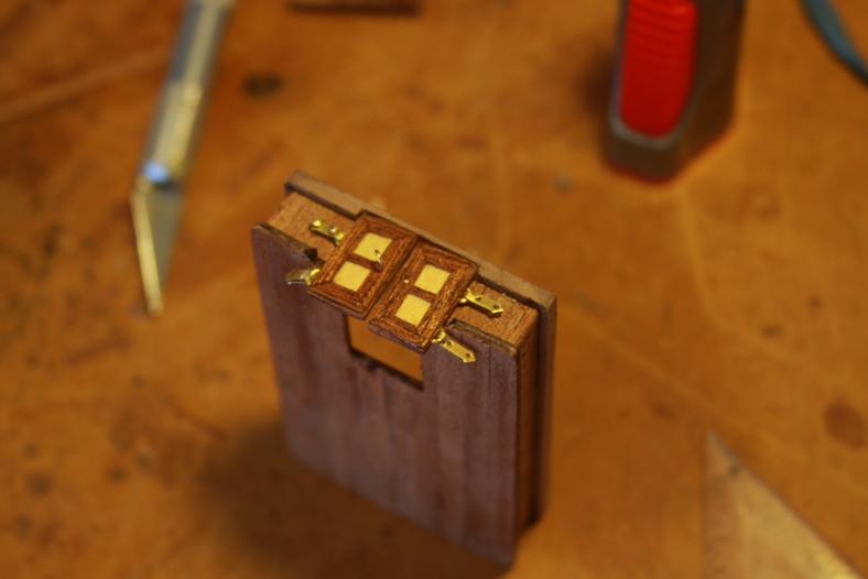
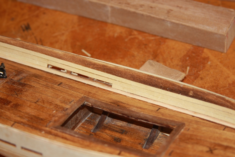
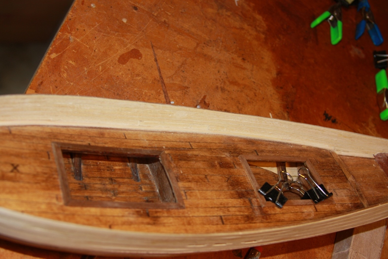
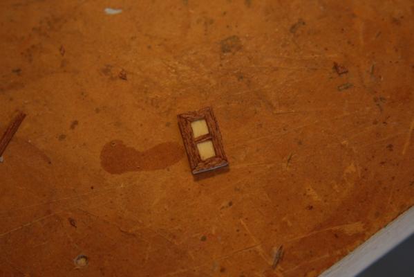
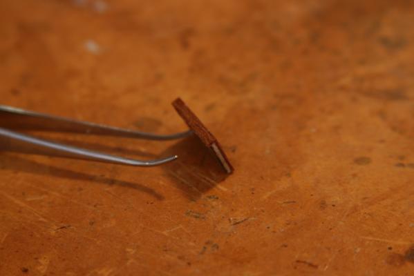
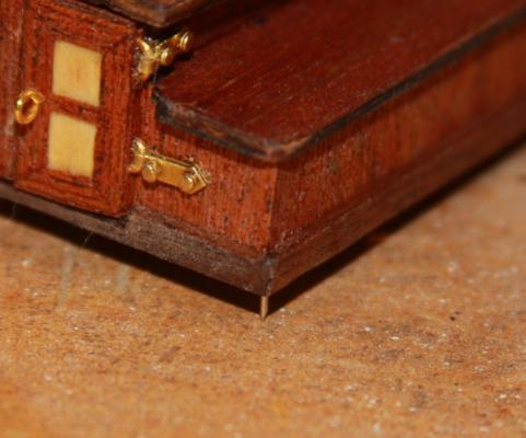
I get board with some of the bits of the ship, so I start messing around with details. I wanted to add some extra features to the lower decks, but I also wanted to be able to see those details. This kit has permanent deck houses. So I devised a plan in which a viewer could remove and replace the deck houses. The doors are framed with thin cut strips of mahogany with mitre cuts. They're mounted with frames made from brass so that they can be opened and closed. I mounted pins on the bottom of the deckhouses, then I drilled corresponding holes into the deck access pieces.


- 14 replies
-
- 1
-
-
- Swift
- Artesania Latina
- (and 1 more)
-
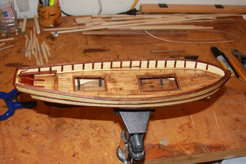
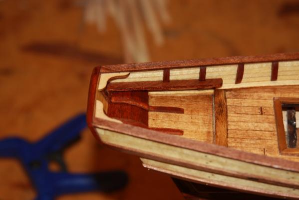
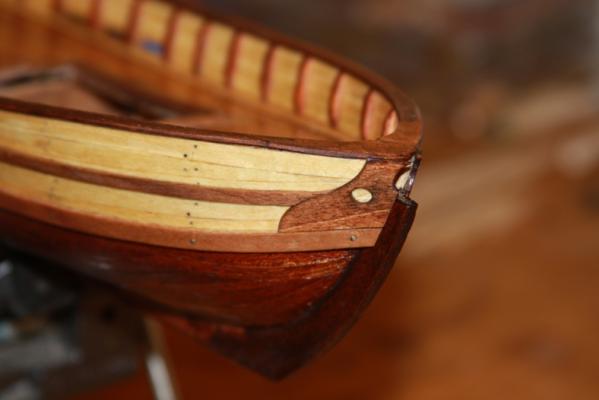
I'll go through this pretty quickly - the inside of the bulwarks are strips of walnut and the rails and wales are both walnut and mahogany strips. The bow of the ship is a little flimsy also and took some "fixing" to line everything up.


- 14 replies
-
- 1
-
-
- Swift
- Artesania Latina
- (and 1 more)
-
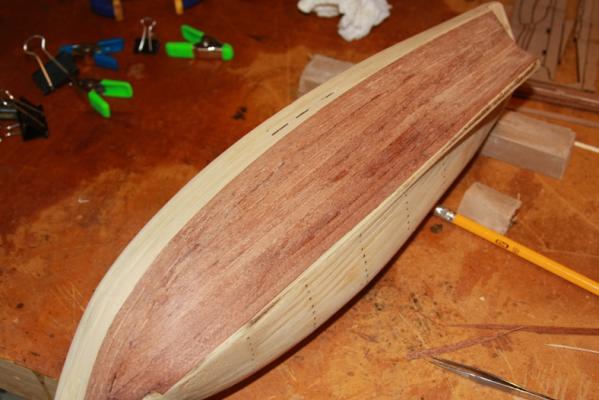
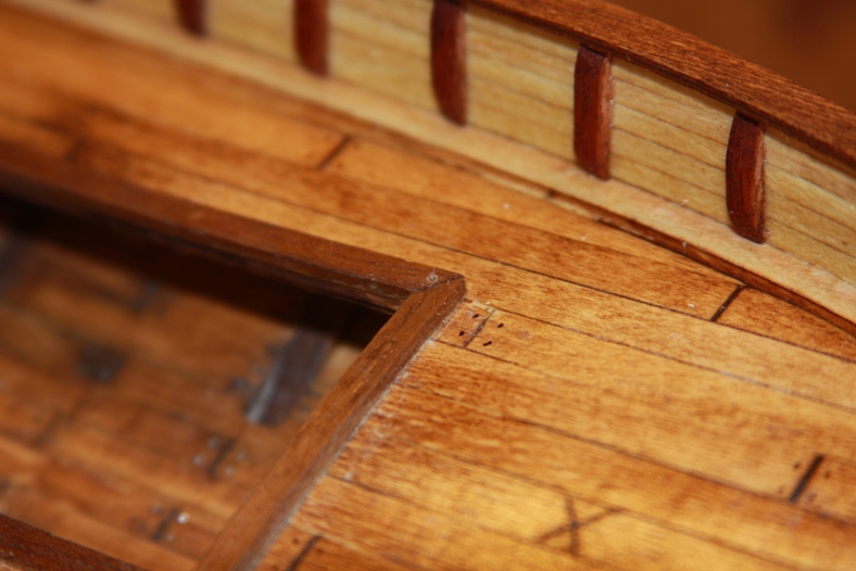
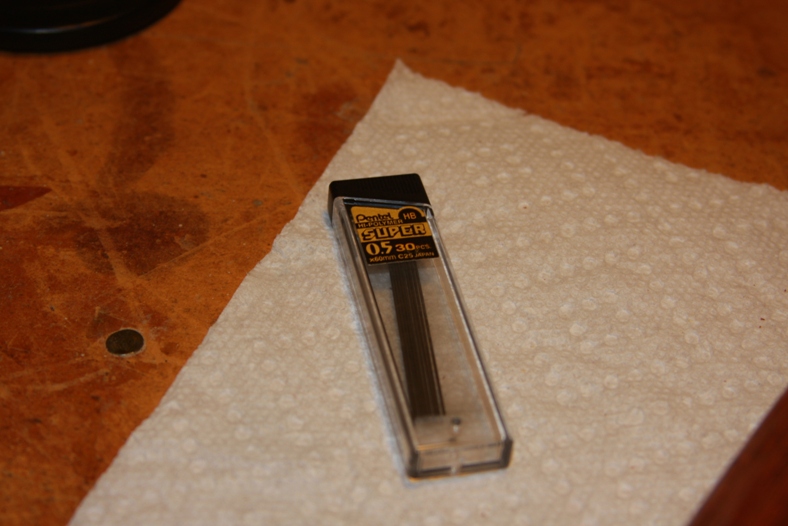
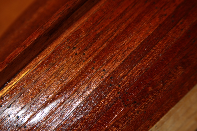
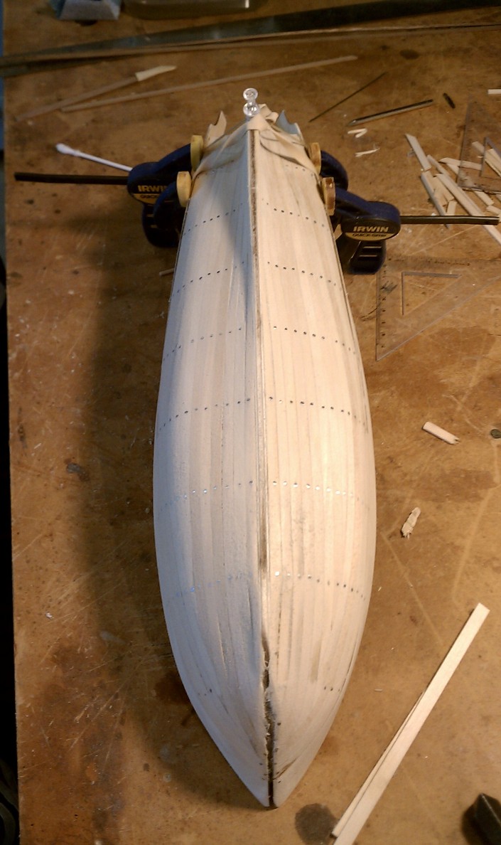
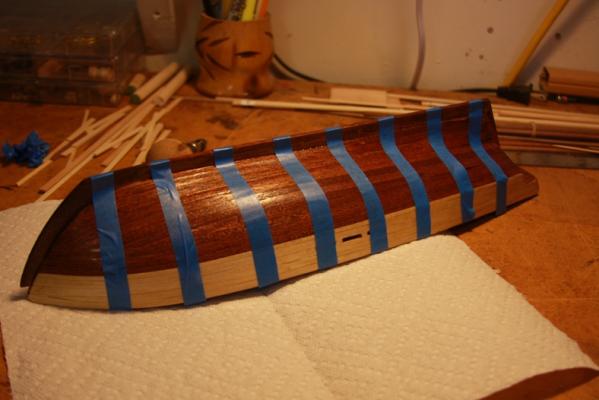
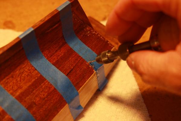
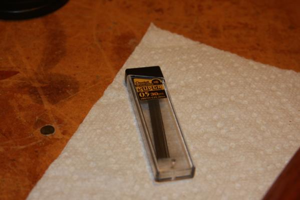
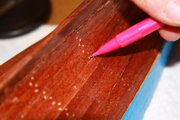
Because of the delicate nature of the hull planking, I used several layers of tung oil and then lacquered with polyurethane before I started working on treenails for the hull. I used strips of painters tape to line up where I wanted the treenails. This also had the benefit of preventing splintering of the hull planking when I drilled. My treenails are .5 mm pencil lead. I poked the pencil lead into the holes then snapped them off. I then sanded down very gently and got a decent end result. The process actually went relatively quickly. Not the exact look I was going for, but it came out ok and was an interesting experiment.

- 14 replies
-
- 1
-
-
- Swift
- Artesania Latina
- (and 1 more)
-
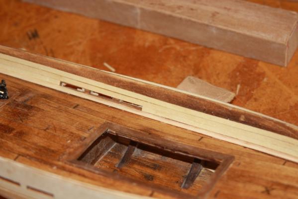
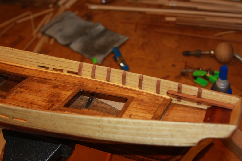
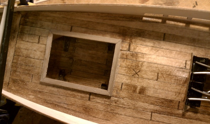
This is better lighting to show the color of the oak stain I used. It also shows the mitre'd borders for deck access. At this point the bulwarks have been added. It was very beneficial for me to mount and glue the bulwarks before I planked the ship. This greatly helped me even out the hull. I planked and sanded the hull. The hull is double planked. It was super important to get the sanding and shaping done properly on the first layer of planking because the second layer of planking is very, very thin and not super high quality wood. I used quite a bit of filler and re-sanded several times using nothing more harsh than 200 to 400 grit paper. Were I to do the ship again, I would likely have planked it with aftermarket wood of better quality.