jack.aubrey
-
Posts
1,268 -
Joined
-
Last visited
Content Type
Profiles
Forums
Gallery
Events
Everything posted by jack.aubrey
-
 . . about reinforcements. . During the assembly of the last bulkhead aft, I immediately worried about the strength of the last segment that connects the keel to the rest of the ship skeleton. So, after having checked in the following instruction issues the next stages of assembly and having understood that in the selected area was not installed anything in contrast with what I had in mind, I decided to reinforce with new pieces of plywood this area. I cut two pieces of plywood that I glued on the deck and on the vertical side of the last bulkhead, this in order to contrast the flexibility of the keel and then I further reinforced the vertical part of the keel by applying one of the two defective pieces distributed in an issue and that will be totally replaced later . So, now the whole poop is more robust. So far, this aspect seems to me, until now, the only flaw in the design of this model although probably everything will settle correctly later. . the fact is that the meantime you run a risk that is better not to deal with. Images 01 and 02 show what I have done in this regard. . 01 02 Finally I made a bit of raw material to reinforce the skeleton in some places that, due to the complexity of the bonding, may not have been perfectly glued. I refer in particular to the junction between the bulkhead and the deck close to the external sides. That area, in some next stages, will have to be smoothed in order to prepare the bevel and there is nothing worse than to have a imperfect bonding when you do that. . but the matter is difficult to explain in words, I will show everything at the proper time. In the meantime, I want to emphasize how I got the material shown below: This is poplar plywood 5mm thick. I sliced in strips of mm. 6 width with my Proxxon table saw. I have a fair number of these tools, a number that will expand soon with three other "new entries". You can avoid buying them but having them greatly simplifies your work. . 03 Kind Regards, Jack.Aubrey High Resolution Images: 01 http://i81.servimg.com/u/f81/12/86/14/83/p1090490.jpg 02 http://i81.servimg.com/u/f81/12/86/14/83/p1090491.jpg 03 http://i81.servimg.com/u/f81/12/86/14/83/p1090493.jpg
 -
Hi Yves, infact the instructions are designed in a way that you can start to work since the availability of the first issue . . This is an approach that is appealing in a particular way to the beginners but it is not the right method for the more experienced modellers. In general the experienced modeller collects a set on at least 15-20 issues and then starts to work, having in this way in mind the final goal. Regarding guns and anchors and whatever else, they are supplied in different weeks and I don't start to mount a gun this week and then repeat the same process two weeks later. I collect all the guns and I assembly all of them in one shot. If I get idle, I have another model to work on, so my time is always allocated. Anyway these instructions are very detailed and if a modeller follows them it is difficult he can make critical errors. These instructions are one of the valued added features of the partworks vs the traditional kits. Sincerely, Jack.
-
Monday, May 28, 2012 New progresses with the guns assembly on the deck . . 01 P1080240.jpg 02 P1080241.jpg See you next message . . Jack.
-
Saturday, May 26, 2012 Today I returned to work with the guns. I'm at a stage of the assembly of the guns that I define "intermediate", there is still a lot of work to do but the more critical activities and requiring precision can be considered concluded. In practice, all trucks have been fixed to the deck below by means of a brass pin that runs through the base of the truck and slips into a hole in the deck. The whole thing is secured with four drops of Attack Gel under each wheel and also the pin is glued to both the truck and the deck. . the pin head can be seen in the images in high resolution. 01 P1080236.jpg 02 P1080237.jpg 03 P1080238.jpg Sincerely, Jack.Aubrey.
-
Friday, May 24, 2013 - mounting the skeleton - part III Today I continued with the assembly of the skeleton. Nothing special to report regarding the assembly and the method adopted: I did exactly like yesterday and the day before yesterday. 01 02 Later, having more time to spend, I proceeded to assemble all those pieces to be applied outside the last blukhead aft. The whole is visible in the next three images, particularly in picture 04. It remains to apply other four pieces on the last bulkhead, but I'll worry about them later, at the present time I prefer not to have too protruding pieces there. 03 04 05 Now there are the next steps, as instructed, where I will have to install the reinforcement of the false intermediate deck. Sincerely, Jack. High Definition Images: 01 http://i81.servimg.com/u/f81/12/86/14/83/p1090485.jpg 02 http://i81.servimg.com/u/f81/12/86/14/83/p1090486.jpg 03 http://i81.servimg.com/u/f81/12/86/14/83/p1090486.jpg 04 http://i81.servimg.com/u/f81/12/86/14/83/p1090488.jpg 05 http://i81.servimg.com/u/f81/12/86/14/83/p1090489.jpg
-
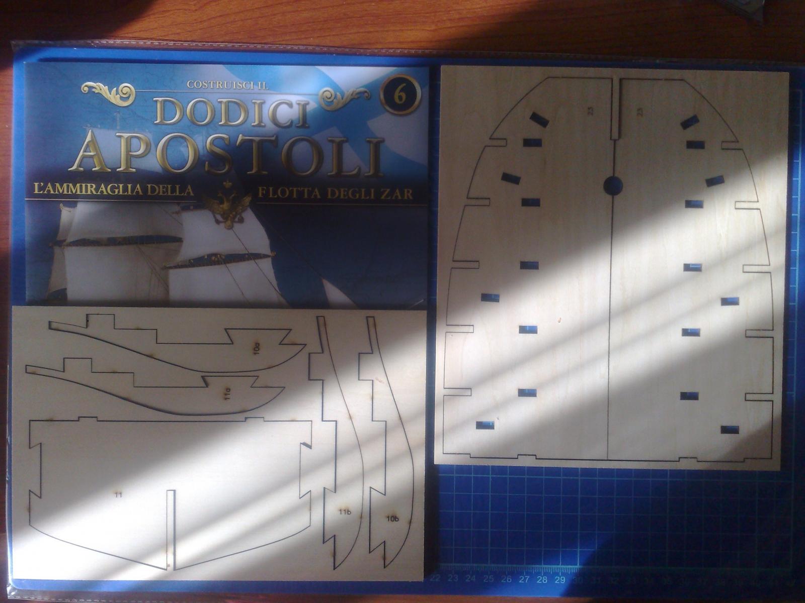
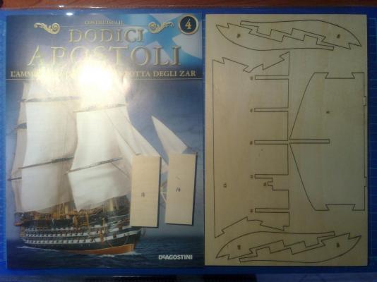
Hi Sjors. There are no drawings supplied together with the weekly issues and, knowing this kind of partworks in the past, there will be no chance for them. Usually De Agostini provides only the plans for the masts and the rigging, nothing more. If you want to reproduce the pieces supplied in the issues, the only way is to make a photocopy of the whole frame containing the laser cut pieces before extracting them. But the problem is: how to take photocopies of them ? Probably you have to find someone in Russia or in Italy that has not yet started this model and take with him an agreement. The official forum of De Agostini in Italy could be a good place to ask this kind of favour . . but the rules of that forum may probably reject a similar request. The step by step instructions (that until now I did not follow) can be seen here: http://www.deagostinipassion.com/forum/posts/list/27322.page An example of the material included is shown in the following two images.

-
Hi Anja, I probably finally found the english translation for "cavallino". It seems to be "sheer". Anyway you get the right concept: it is a deck curvature running from prow to poop, with the topsides higher that the centre. Thanks very much for your cooperation. There is another curvature for the ship decks, running from left to right called "bolzone"; its english translation is "camber".
-
Friday, May 24, 2013 - mounting the skeleton - part II . . the assembling of the Twelve Apostles skeleton continues. This afternoon I glued six more bulkheads, the ones below to the second segment of the deck and then I also fixed the two elements of the central deck segment. As for my work of yesterday, the procedure was exactly the same and even today I have not encountered any problems whatsoever. Now the glue is quietly drying, I will finish tomorrow with the third segment. 01 02 03 Then, having nothing better to do, I started working on the first bulkhead, where there is to install a number of new elements that will form the backbone of the bow. Here, too, nothing difficult except a little patience. . 04 05 High Resolution Images: 01 http://i81.servimg.com/u/f81/12/86/14/83/p1090472.jpg 02 http://i81.servimg.com/u/f81/12/86/14/83/p1090473.jpg 03 http://i81.servimg.com/u/f81/12/86/14/83/p1090475.jpg 04 http://i81.servimg.com/u/f81/12/86/14/83/p1090476.jpg 05 http://i81.servimg.com/u/f81/12/86/14/83/p1090477.jpg
-
Thursday, May 23, 2013 - starting to get serious. . I reinforced the famous "fragile" bulkhead which, among other things, had almost immediately broken, by applying two strips of walnut 5 x 2 in the manner shown by the first picture. The reinforcement is applied where no one will bother in the future, I just have to do a small refinement before mounting it. 01 Then I started to lay down, in a definitive way with the glue, the top seven bulkheads and the two elements of the first segment of the deck. As I mentioned earlier I glued rather quickly the bulkheads from the second to the seventh, followed immediately by gluing the two half deck elements. In this way everything went perfectly square shaped, without worrying too much, taking advantage of the time needed (about 15 minutes) by the glue to get grip. To hold the half decks in place, given the presence of a small "cavallino" (I don't know the nautical english term), I used a dozen brass nails (you can see them probably in the high resolution photos). Finally I installed the first bulkhead, whose verticality was assured by the presence of the deck and then I applied the reinforcements for the bow. . 02 03 04 Now everything is resting to complete the drying process of the glue. I forgot a thing: of course all the glue in excess was removed during the process with a small brush. Sincerely, Jack. High Resolution Images: 01 http://i81.servimg.com/u/f81/12/86/14/83/p1090465.jpg 02 http://i81.servimg.com/u/f81/12/86/14/83/p1090460.jpg 03 http://i81.servimg.com/u/f81/12/86/14/83/p1090461.jpg 04 http://i81.servimg.com/u/f81/12/86/14/83/p1090463.jpg
-
Thursday, May 23, 2013 I take this opportunity to inform you that, as I had expected, the bulkhead number 28 had a short life without being reinforced. Yesterday, while I was manipulating the hull to dry install the last segment of the deck it took a wrong move. . and was immediately broken. . Never mind, I immediately recovered it and I took the opportunity to reinforce the fragile area with a strip of walnut 5 x 2mm. However, it is a detail that should be kept in mind for those who have already gone there. Regards, Jack.Aubrey
-
Thursday, May 24, 2012 - Starting the installation of the guns Now the time has come that I can no longer postpone the installation of the twelve guns on the upper gun deck. For this occasion, because there are no jobs that make dust or mess, I temporarily transferred the site at my house so that I can use all the useful moments to complete this activity that I remember often being long and tedious. This morning I started with the positioning of the various pieces that will be placed on the upper deck: I drilled holes for fixing "pazienze" and "cavigliere" around the mainmast, I similarly prepared the holes for the joints for the structure to support the ship boats, and finally the holes to "nail down" the carriages of the guns, when it's time to fix them permanently. And now this deck, as of now empty, is "magically" filling up. . 01 P1080234.jpg 02 P1080235.jpg From a very early consideration there are three aspects to keep in mind: 1) in the images are visible five guns per side, the sixth is almost hidden under the half-deck above. This trolley and its cannon can not be fixed by a metal pin as it is not possible to bore the necessary hole. In addition, the fitting of the same is virtually impossible, unless contortions and acrobatics think out of my reach (and patience). If we consider that when you apply the gangways these two guns will be almost invisible, I think I will just paste them on the deck using the glue which I think is the most suitable for this type of bonding: two-component epoxy glue. It take long time to dry, but on the other hand are as strong as, and perhaps more of Attack and less sensitive to sharp blows that cause the release of Attack. 2) Similarly, the pair of cannons on the right are partially covered by the forecastle, but here the work is easier: first can be fixed with the pin and also the fitting is possible, at least for the exposed side. 3) The structure for the housing of ship boats, positioned as instructed by De Agostini, is a place that hinders the operations of the second pair of cannons on the right. And so I'm gaining seriously consider the idea of moving it to about 10/12 mm to the left. The problem is that I have no idea from the instructions in my possession, if the area would go to be occupied partially, that is marked in the black box below, you will have to accommodate other superstructures. The plans Sergal would seem an area free, apart from the ladders to access the decks. . 03 P1080234M.jpg Cheers, Jack.Aubrey
-
Sunday, May 20, 2012 This is the "small" ship boat, largely completed. It is not really 100% finished because some small details (rudder, oars, coils of rope and dry) are missing, but the more, that is the hull as a whole, is finished. I must admit this boat came better than the "big" one and I think the best method would be to build a prototype, to make the necessary experience and then, enforced with this knowledge, build the final models. Obviously the time of their completion lengthens but the result improves. 01 P1080229.jpg 02 P1080231.jpg 03 P1080232.jpg 04 P1080233.jpg Kind regards, Jack.
-
Wednesday, August 24, 2011 - End of "Grisella Party" Eight days before the beginning of the "Grisella Party" (this is the name I decided for this process), today I finally finished tying all the ratlines of the shrouds of the mainmast. It was an hard way and I am fully aware of the huge work carried out by those who have already tried this experience on a complete sailing ship. Compared to my work on a tree alone and not fully rigged I do not know how I would have tired and nervous. After learning the specific technique to make the knot to be used (taken from the book of Lennarth Petersson's "Rigging Period Ship Models") I started slowly. The first few days after tying 5 or 6 lines I had to stop, but in the last times I could make even fifteen without stopping. Luckily in this period of time I am involved in making the caregiver to my mother-in-law, so I was able to capitalize on the availability at any time of the laboratory, and I had the opportunity to play several sessions per day. I confess I had not even tried to run the knot used for the head and the tail of "griselle" therefore also in this case I used the same knot for the internal ones, which holds up very well. However, I applied a coat of diluted glue on the knots before cutting the twine in excess. Here are some pictures of the work. 01 Cross%20Section%20Santisima%20Trinidad/P1070756.jpg 02 Cross%20Section%20Santisima%20Trinidad/P1070757.jpg 03 Cross%20Section%20Santisima%20Trinidad/P1070762.jpg And here finally the lower element of the main mast. While the other shrouds are complete, here there are only four while in the real ship I think there were twelve. 04 Cross%20Section%20Santisima%20Trinidad/P1070763.jpg 05 Cross%20Section%20Santisima%20Trinidad/P1070765.jpg Now the adventure continues, but for now I want to recover from the stress, release the hands that have a tendency to knot themselves and rest for a couple of days. In the meantime I'll give some coat of paint to the display board. Sincerely, Jack.Aubrey
- 106 replies
-
- 5
-

-
- deagostini
- finished
- (and 2 more)
-
Wednesday, May 16, 2012 Two photographs to show the "big" boat practically finished. Probably when I'll have finished the little, too, I'll build a couple of buckets that I will place on the bottom. 01 P1080220.jpg 02 P1080222.jpg I promised not to publish images of the "small" boat, until it was over, as in fact it would be a duplication of the construction process almost like the "great" boat, but I remembered that I missed an important step regarding the emptying process of the internal side of the hull, when the same was being detached from the building slip. So I go further now to fill the gap showing the "small" with the third planking terminated with the interior emptied and ready for next steps. 03 P1080223.jpg 04 P1080224.jpg Kind regards, Jack.Aubrey.
-
Thursday May 10, 2012 Tired of chasing the construction of the boats, I took a couple of "sabbatical" days and I enjoyed it to mount some superstructures in the bow and stern area. I had already prepared them long time ago. . in short, a slight deviation from the usual routine of last recent times. Attached are some pictures of the superstructures under discussion. Unfortunately, the red color is not very "photogenic", as I have explained a bit of posts back. 01 P1080179.jpg 02 P1080177.jpg 03 P1080178.jpg 04 P1080184.jpg 05 P1080185.jpg Kind regards, Jack.
-
Wednesday, May 9, 2012 I photographed the rudder pintles and gudgeons I scratch build long time ago. A big job that I mentioned a few posts ago. The rudder is not stained plywood but true solid mahogany. 01 P1080180.jpg 02 P1080181.jpg 03 P1080182.jpg See you next time, Jack.Aubrey.
-
Hi Yves. Your comment is very interesting . . You highlighted a point of weakness of this kind of kits: the huge number of copies of the same laser cut elements cannot be obtained from the same sheet of wood and, consequently, the pieces may differ in thickness. And you have to consider that i received from an unofficial source that every week De Agostini sells in Italy and in Russia an unbelivable number on copies of its partwork (+/- 80.000), This is a huge number and the problem seems to be solved by imposing to the chinese company who makes the components severe quality standards. There are also some tricks: for example the three element that make up a bulkhead are cutted from the same plywood sheet. So the bulkhead is unaffected by that problem. I know Amati is selling its Black Pearl using MDF for the keel, bulkheads and other pieces. I made in the past some comparative tests between plywood and MDF and I consider plywood, if of good quality, superior to MDF. Anyway MDF may be considered a future solution and evolution in shipmodeling. But I think also its "formula" should be sligthly modified to adapt to shipmodeling needs . . Continuation . . Another image of the skeleton dry mounted: 01 Then, as anticipated, I disassembled everything and I proceeded to fix the reinforcements of the keel. The pieces were a little generous in width, so I had to remove with a sanding block the excess. For gluing I used the building slip: I inserted the keel inside it, then I inserted the two bulkheads involved in the installation of the reinforcement and I modified the reinforcement block until it was insertable effortlessly between the two bulkheads. At this point I switched to gluing, pinning them together with clamps. I aligned the reinforcements to the bottom line of the keel, although this will force me to shape flush to the bulkheads the excess. It will provide a point of support of the first strip (starting from the keel) that will contribute to a more correct positioning and anchoring. 02 03 I also made a slight change to the building slip, even if it is not worth to show it in pictures, because it is of little importance in the general economy. See you next time, jack.Aubrey. High Resolution Images: 01 http://i81.servimg.com/u/f81/12/86/14/83/p1090451.jpg 02 http://i81.servimg.com/u/f81/12/86/14/83/p1090454.jpg 03 http://i81.servimg.com/u/f81/12/86/14/83/p1090455.jpg
-
First of all, thanks you all for the appreciations to my new model, I've just started a game that will probably last not before 2016. . Tuesday, May 21, 2013 - Dry assembly, continuation . . Continues in this message the dry assembling of the skeleton. . I applied all the bulkheads and the remaining segments of the lower deck, evaluating the precision and the easy assembly. Compared to the partial work done yesterday anything happened that made me reconsider the plan that I set yesterday, in fact I am convinced even more on the method I suggested. The images below show the skeleton, dry mounted, from various viewpoint. Once again I must stress the extreme precision of the project and laser cutting. To complete the test fitting I hardly had to use the file to correct some imperfections. Truly admirable. 01 02 03 04 05 After the dry assemply . . I voluntarily limited it at this point because I do not want to progress further this first phase, I then removed everything, put all under press, that is "under glass", the various pieces and I have dedicated myself to the reinforcements of the keel. We will address this issue in the next message. Cheers, Jack.Aubrey High Resolution Images: 01 http://i81.servimg.com/u/f81/12/86/14/83/p1090446.jpg 02 http://i81.servimg.com/u/f81/12/86/14/83/p1090447.jpg 03 http://i81.servimg.com/u/f81/12/86/14/83/p1090448.jpg 04 http://i81.servimg.com/u/f81/12/86/14/83/p1090449.jpg 05 http://i81.servimg.com/u/f81/12/86/14/83/p1090450.jpg
-
continuation . . More images of the skeleton dry mounted . . 01 02 03 04 05 However, this experience helped me, as well as to verify the correctness of the parts and the whole, also to define the process that I will follow for the final assembly with glue: - I will glue the first bulkhead only after having applied the lower deck, this makes it easier to install the two half bridges and defines the correct mounting position; - I will glue in a single session, rather fast, the next six bulkheads, without worrying too much for the angle of 90°, favoring instead the speed of execution; - Before the glue used to bond the bulkheads has the time to dry, I immediately install the two half decks no. 23, if the case I will fix the deck with some fine brass nails (Amati) not completely hammered so that you can take them out once dry; - Finally I will mount the first bulkhead at the bow; Once finished the area of the first segment of the deck, I will proceed in the same way for the second segment and then to the third. I hope I explained clearly, kind regards, Jack.Aubrey. High Resolution Images: 01 http://i81.servimg.com/u/f81/12/86/14/83/p1090429.jpg 02 http://i81.servimg.com/u/f81/12/86/14/83/p1090431.jpg 03 http://i81.servimg.com/u/f81/12/86/14/83/p1090432.jpg 04 http://i81.servimg.com/u/f81/12/86/14/83/p1090433.jpg 05 http://i81.servimg.com/u/f81/12/86/14/83/p1090434.jpg
-
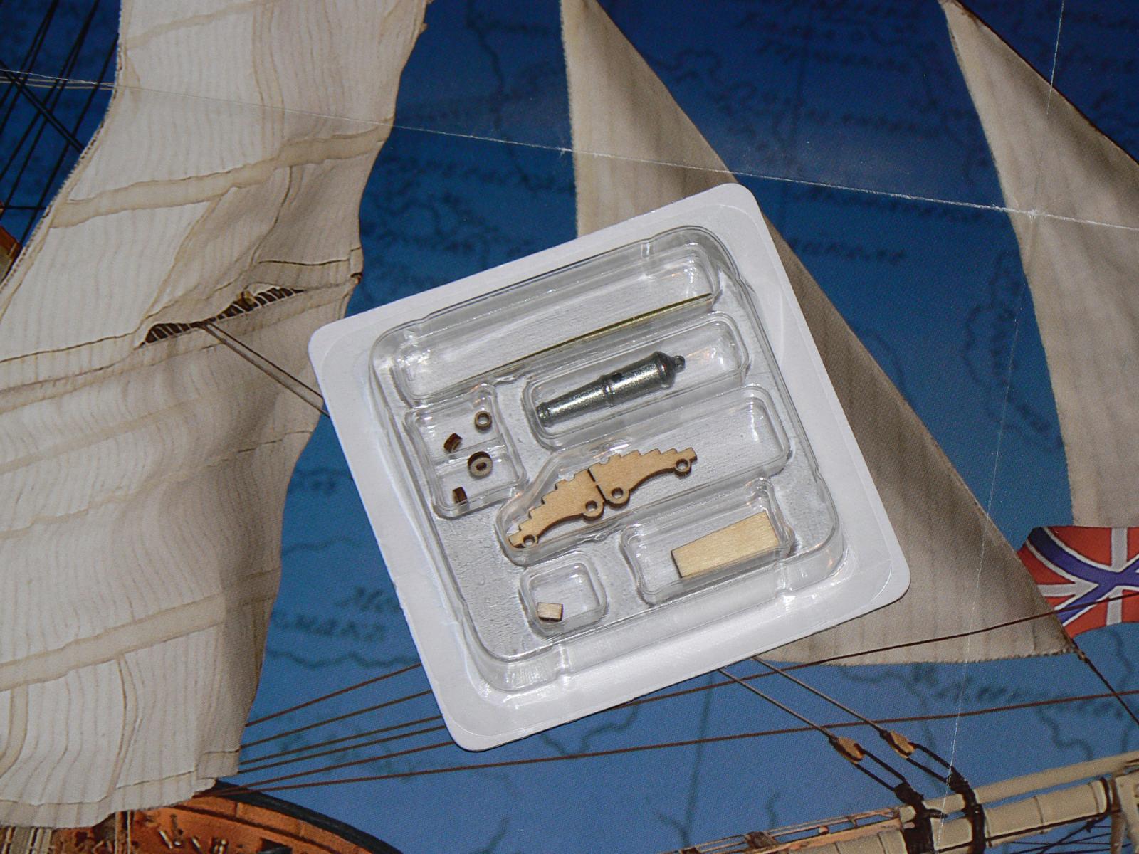
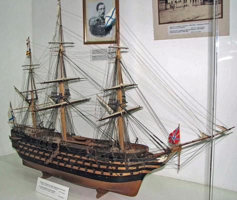
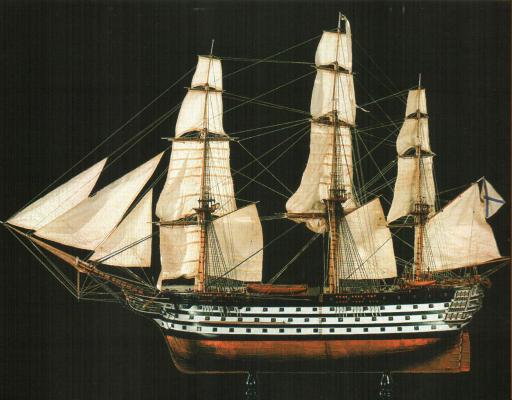
The next picture shows the model from Lev Alyoshin (Alechine), located in Sevastopol, taken fron Artesania Latina as main reference for their project of Twelve Apostles: This is another model of Twelve Apostles, located in St. Petersburg. It seems there is a third model located in Vladivostok . . The next image is the cover of the book I presented in my first, introductory message: And this is a gun supplied in the first issue of the partwork . . Cheers, Jack.Aubrey.


-
continuation . . Here are shown the last remaining bulkheads, assembled and waiting for the glue being completely dry. 01 In the second and third picture you can see the last bulkhead, the number 28 assembled with the pieces 28a and 28b. The bulkhead is assembled above the famous cutting mat provided by De Agostini as a gift. Characteristic of this pad is to implement a centimeter net. It was very useful for me to assembly the components "a" and "b" of each bulkhead in a symmetrical manner. This because it allowed me to check their position, which must be equidistant from the centre. 02 I think the trick is clearly understood by looking at the photo below. About bulkhead no. 28, I believe that, assembled in this way and left as it is, should be pretty weak, more precisely in the point of bonding of the elements "a" and "b". I've also seen in later stages of the assembly process that this potential weakness does not improve with the addition of the lower deck; it improves only after applying the three levels of reinforcement for false decks. So as a precautionary action I think it's better toughen up the piece by gluing a strip on the side where it will not be present the deck, that is, on the side facing towards the stern. The thickness of the strip should be at least 2mm. 03 Finally I worked in the trial of dry mounting the bulkheads now ready. I took the keel (where at the moment have not yet been glued reinforcements at three connections), I inserted into the building slip and I placed the bulkheads. Then I tried to place the two segments on the lower deck that ends near the bulkhead no. 10 which is the seventh from the first. The pieces are perfect. . they fit with incredible accuracy. . 04 05 See you next time, cheers, Jack.Aubrey High Resolution Images: 01 http://i81.servimg.com/u/f81/12/86/14/83/p1090426.jpg 02 http://i81.servimg.com/u/f81/12/86/14/83/p1090439.jpg 03 http://i81.servimg.com/u/f81/12/86/14/83/p1090438.jpg 04 http://i81.servimg.com/u/f81/12/86/14/83/p1090428.jpg 05 http://i81.servimg.com/u/f81/12/86/14/83/p1090430.jpg
-
Thank you very much, Sjors, for the transaltion. Cheers, Jack.
-
Continuation. . the "scaletto" In the first image a group of bulkheads mounted and held under weight for a few days. . 01 Following three images of the mounting "scaletto" (i don't know the right english term, can someone help?) that I have prepared for this model. As you can see it is very simple and can not yet be considered completely finished. . once that it will contain the keel I think to add blocks fore and aft to hold everything. 02 03 04 Two lines again regarding "scaletto": I found a table at a wood store of paulownia (800 x 300 x 18), a light wood but very stable. I derived from it, through my table saw, a table by a 800 x 250 and with the waste I manufactured the side supports of the keel, that have been glued on the table. Finally, a special thought to the designer of the skeleton of our model. . really studied well, very nice and above all very original. . a big step forward compared to the Victory and Sovereign. . although it would be impossible to do so well without a CAD project and without the cutting tools laser controlled by computer. . Kind regards, Jack.Aubrey. High Resolution Images: 01 http://i81.servimg.com/u/f81/12/86/14/83/p1090411.jpg 02 http://i81.servimg.com/u/f81/12/86/14/83/p1090330.jpg 03 http://i81.servimg.com/u/f81/12/86/14/83/p1090331.jpg 04 http://i81.servimg.com/u/f81/12/86/14/83/p1090332.jpg
-
Though written in Italian, this discussion shows the assembly instructions of the first 20 issues of the Twelve Apostles . . http://www.deagostinipassion.com/forum/posts/list/27322.page I think the pictures are self explaining, note the complexity of the skeleton . .
-
Thanks to all of you for the positive comments . . My opinion is that this new kit, after +/- 20 weekly issues, is a small jewel of CAD design and the "hard work" is obviously done by CNC machine piloting laser cutting machines. The pieces are so precise that there is often no room for the glue . . I use to enlarge with a small file the interlockings between the various parts to be sure the glue achieves its objective !! Cheers, Jack.