


amateur
-
Posts
3,462 -
Joined
-
Last visited
Content Type
Profiles
Forums
Gallery
Events
Posts posted by amateur
-
-
I know the story (at least the MSW1-version of it)
Had a discussion with him on the place where to find drawings of both Java and O19 in the Dutch archives.
Jan
-
It is indeed HrMs Java down south.
You're pretty good in searching. Need to dig a bit deeper.....
Perhaps some obscure laker

Jan
-
No, not a tug. World has indeed turned upside down
 :)
:)Next one will be a tug.
Jan
-
Next one

-
Bingo: schooner reylands, rebuild as a brig (hispaniola) for the movie treasure Island.
Jan
-
Searching for ship+movie ends up in lots of pics of starship Enterprise, titanic or horation hornblower.
All three are not correct, I presume....
Jan
PS or pirates of the carribean, but it's certainly not the plack pearl
-
-
Sure you don't use Google picture search
?It is Finland.
Jan
-
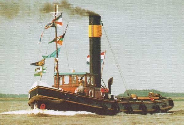
you should be able to recognize her
Actually, you're about halfway, by recognizing her as a dutch tug
Jan
-
Here's my next one for you.
Jan
-
-
-
was there ever a movie on Minnesota?
It's the Russians: Potemkim
Jan
-
Yeah, that's what I discovered: Titanic has four funnels
(but she was also in a famous movie
)Jan
-
Or is the name of the file just a red herring ....
Jan
-
You should rename your file before uploadingh,
otherwise it's too simple
Jan
-
This game is rapidly changing into 'find were the name is'-game
And as you have only one 'non-laker' you decide to concede.
We understand .....
Jan
-
I also used Bob's method.
I found it useful to mark the centre of the dowel with a small pinhole before starting the tapering.
That helped to keep the whole thing more or less centered.
Jan
-
Yep, you've seen her before.
Thereofre, I should not accept Noordzee as an answer
However, as Rode zee (which is the one in the picture) and Noordzee are completely identical (although guys who actually have sailed on her tell that there are differences between the sisters), feel free to present us a great laker
Jan
-
it is
Jan
-
Great! (and large with the masts on...)
Jan
-
Ah, that's long ago I have posten one.
Here it comes (dont tell Andy/realworkingsailor, he will not like this one)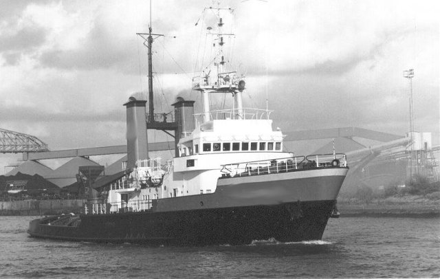
-
First I thought mediterranean, but then I realized: it looks like a Dutch or German 'kotter'.
going through a list of sail Amsterdam and Sail de Ruyter, I came across her name: Thalassa
Jan
-
I have way to go.....
I used to be a rear admiral
Jan

Surabaya by Piet - 1/80 - Mid 17th-Century VOC ship
in - Build logs for subjects built 1501 - 1750
Posted
He made room for it in advance, so I think he will.
Jan