HOLIDAY DONATION DRIVE - SUPPORT MSW - DO YOUR PART TO KEEP THIS GREAT FORUM GOING! (Only 13 donations so far - C'mon guys!)
×


Jason Builder
-
Posts
219 -
Joined
-
Last visited
Content Type
Profiles
Forums
Gallery
Events
Everything posted by Jason Builder
-
 Hi Everyone!! Made some progress this evening on the rudder and pintles and gudgeons. I built up the rudder and tiller including a functioning/pivoting tiller extension and a tiller extension clip mounted on top of the tiller. In a deviation from the stock kit I made up brass pintles and gudgeons using brass brads and small brass tubing. Other than that, just painting and sanding the hull and spars.
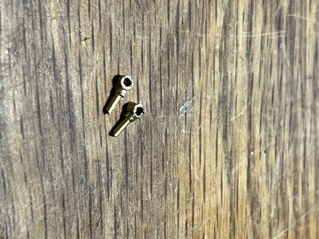
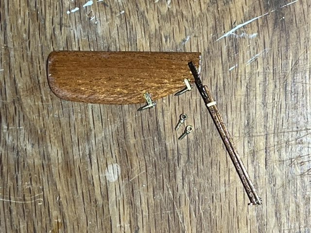
- 33 replies
-
- 1
-

-
- Optimist Dinghy
- BlueJacket Shipcrafters
- (and 1 more)
-
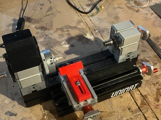
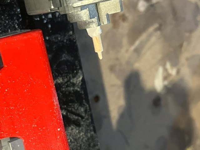
Little bit o work on the sprit tonight. The ends of the sprit on opti's are pin shaped for rigging. I shaped the pins by turning the sprit down at the ends on my mini lathe. I wrapped the sprit in paper to protect it from denting in the 3 jaw chuck, which worked well. Happy with results. This job could be done by carving down the end with a razor or by sanding it down with a file, but I like playing with tools so used my little lathe. Some photo's are below. I didn't even use the tool rest, I used a file and just held it up the the spar end to get the pin shape I wanted.
- 33 replies
-
- 1
-
-
- Optimist Dinghy
- BlueJacket Shipcrafters
- (and 1 more)
-
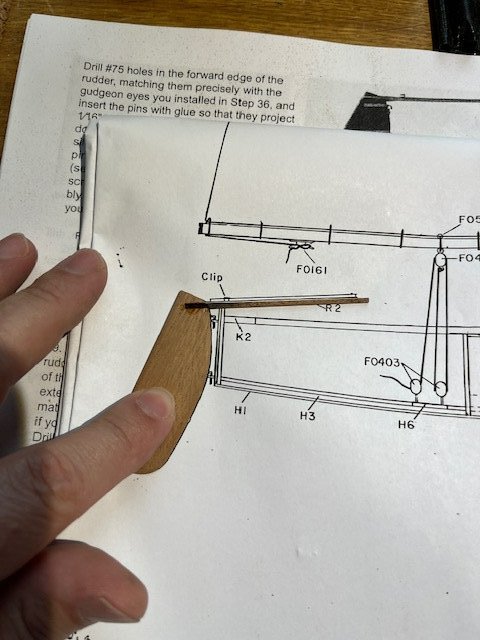
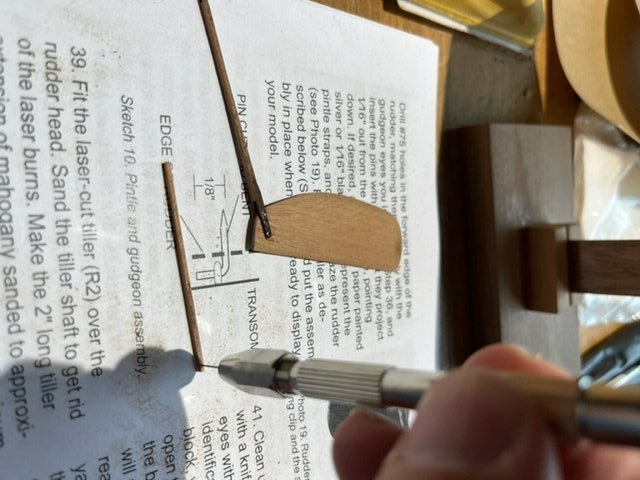
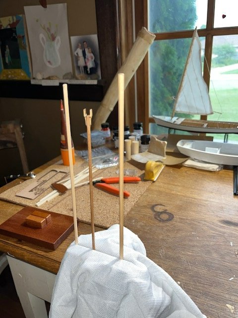
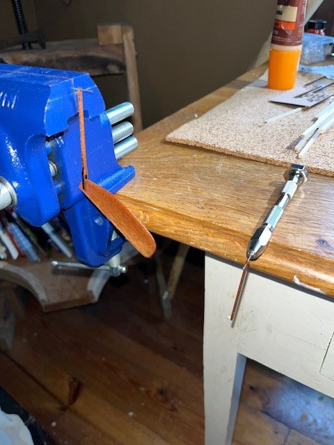
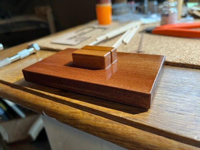
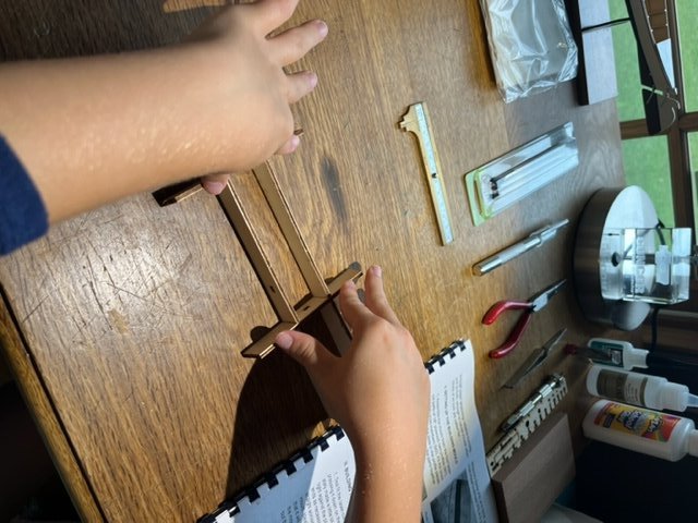
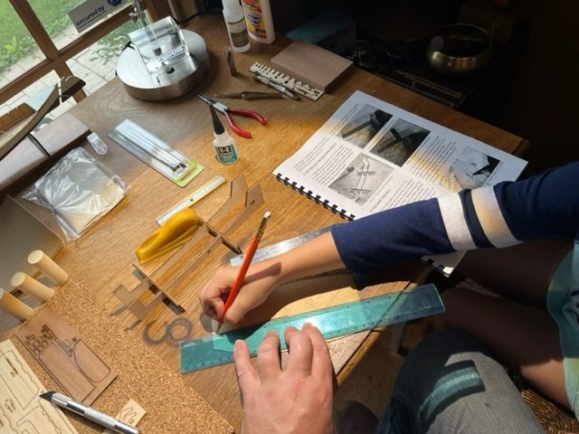
Bonjour!! Well I'm cruising along on this project, both because it's fun, and because I just ordered the Billing Boats Oseborg Viking Ship kit. 1st coat of white paint is drying on the hull. The kit comes with matte white for the hull, but I think I am going to finish it with gloss white. I remember the opti's at the lake being more shiny than matte. I will also be finishing it with varnishing spars rather than aluminum painted spars (even though my kids sailing school boats did have aluminum spars....so I guess I'm just finishing this thing the way I want it to look). I sanded the foil shape into the rudder and also sanded down the tiller and tiller extension. In this photo I am using the plans to ensure the tiller is glued to the rubber at the correct location and angle (I decided to glue the tiller to the rudder , not to pin it). Using the pin vise and drill bit (included in the kit! and the pin vise is nicer than the old one I had, so I am happy about that) to drill the mounting hole for the tiller extension: Using pins to suspend the tiller and extension for varnishing: I cut the boom and attached the boom jaws, sprit, and mast to length, sanded them and now varnishing them. The ends of these spars will be painted gloss white, and it is that tip end that I have in the jaws of the bench vise: As long as I was varnishing, I built up the display stand (sanded all sides, chamfered all exposed edges with sandpaper) and applied 1st coat varnish: That's all for now folks. Have a great day!
- 33 replies
-
- 4
-
-
- Optimist Dinghy
- BlueJacket Shipcrafters
- (and 1 more)
-
Ahoy, Sanded, filled any dents, sanded hull again inside and out. First coat of primer applied, and a coat of varnish on the dagger board in the background.''
- 33 replies
-
- 4
-
-
- Optimist Dinghy
- BlueJacket Shipcrafters
- (and 1 more)
-
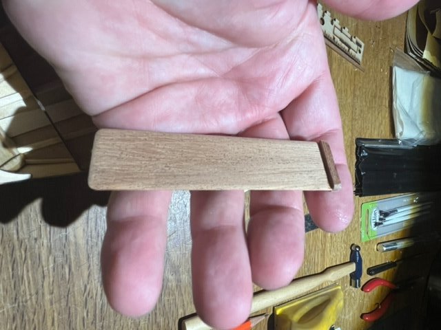
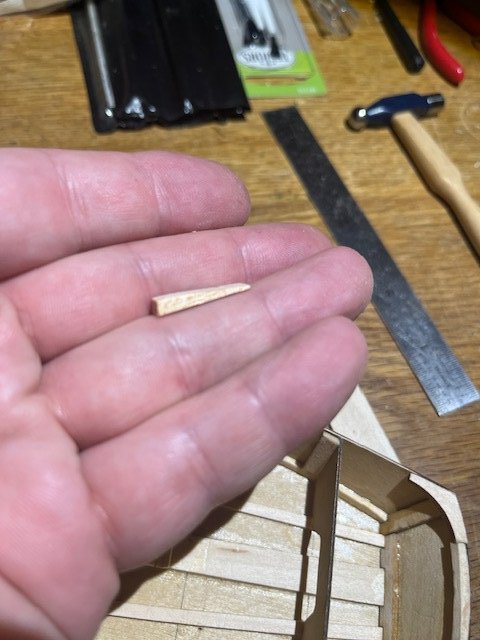
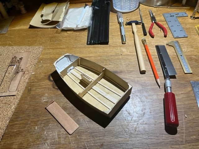
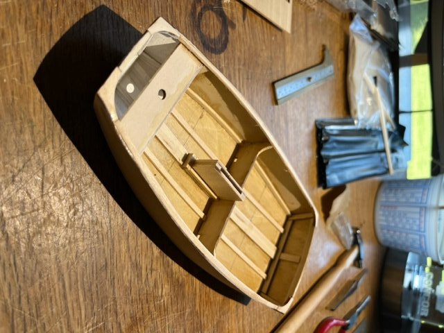
Thanks for the encouragement! Here's the latest progress: Corner gussets and daggerboard trunk installed: Daggerboard sanded to foil cross-section, and assembled: Shaped the mast-step taper block: Installed mast step block: Painted the fore section of the inside of the hull prior to installing the mast step thwart: Mast Step Thwart and gunwhales installed. I cut the gunwhales to length first, then carved the ends to fit the corner gussets, then soaked them in hot water, then pre-formed them by forming them into a curved shape using pins and I cork board until they dried in a curve, then glued them into position.
- 33 replies
-
- 2
-
-
- Optimist Dinghy
- BlueJacket Shipcrafters
- (and 1 more)
-
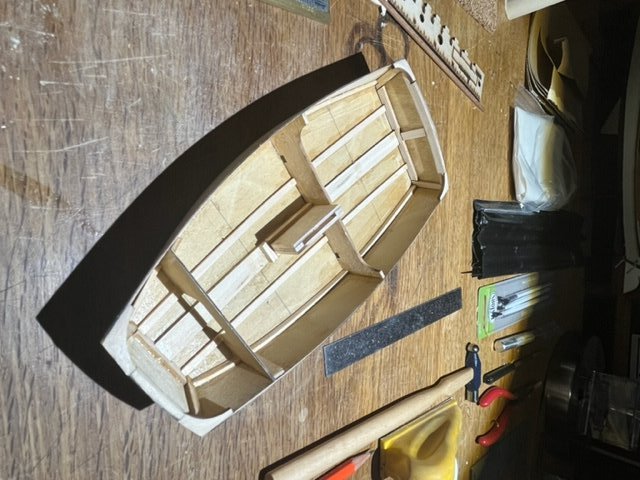
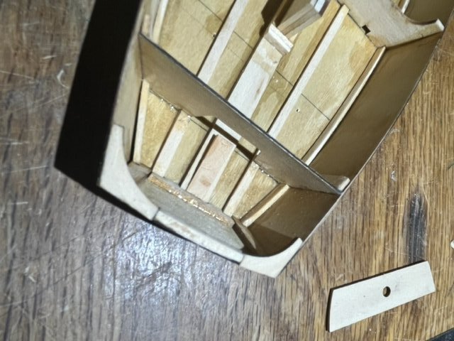
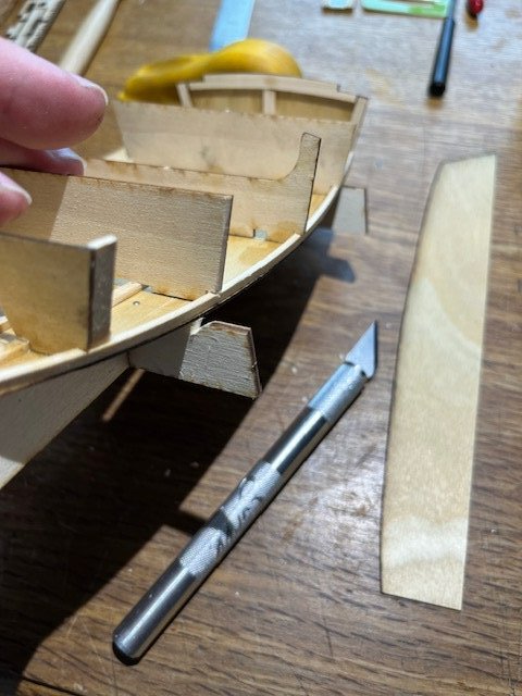
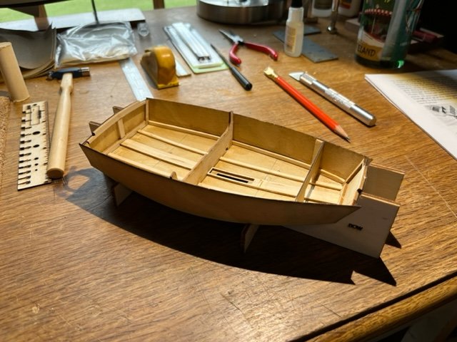
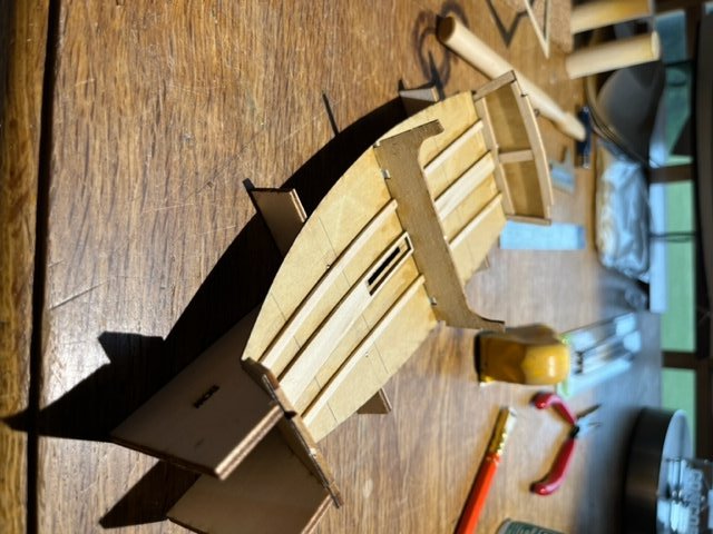
What a fun morning we had! With the chine stringers glued in place, we set the temporary form/bulkheads in place to prepare for gluing on the hull sides. In the first photo below one can again see the error of my ways regarding stringer spacing. The bulkhead closer to me when I took the picture is the temporary form. The bulkhead in the background is the one that will eventually support the mast thwart. The two narrow stringers running along the hull bottom are supposed to run through well fit notches in both those bulkheads, note that I had to cut the notches away into larger openings that fit the actual location of the stringers. With the forms in place, we chamfered them and trimmed/chamfered the chines and bottom to prepare for attachment of the sides. Below photo is of the bottom and the chines carved, sanded and ready for the hull sides. Hull sides glued in place!
- 33 replies
-
- 6
-
-
- Optimist Dinghy
- BlueJacket Shipcrafters
- (and 1 more)
-
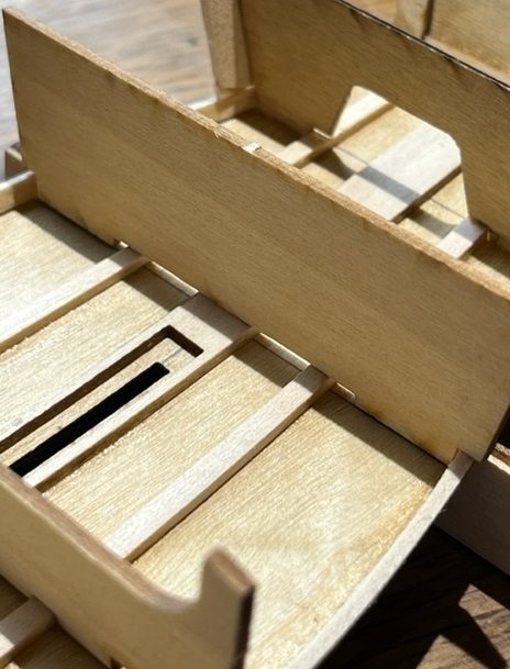
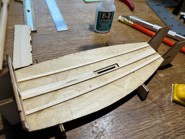
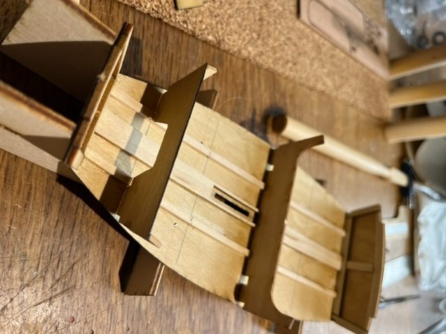
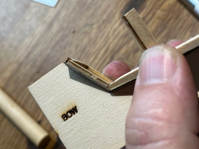
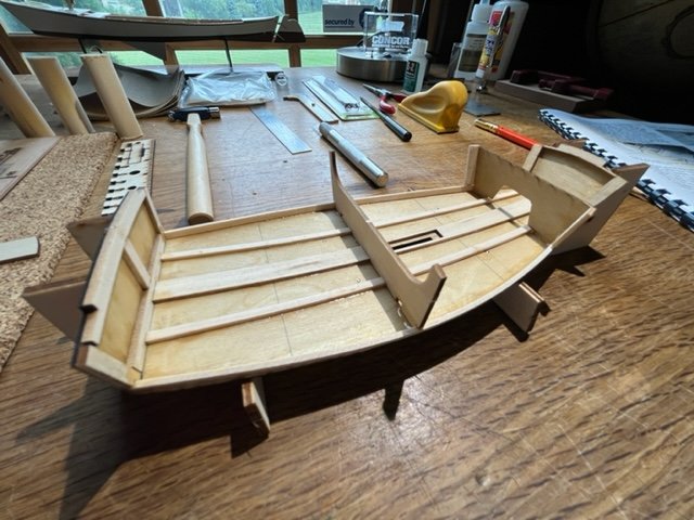
Hi Again, We took a little break and then got to gluing up the hull! First we glued the aft transom in place, then we glued down the floor stringers using the temporary positioning transoms. Had one of the temporary positioning transoms in the wrong spot, 1st mistake of the build! Woe is me! More on this stringer positioning business later. Here are the stingers glued down. We had a spacer in the wrong location so the stringers are a bit too close together towards the front of the dingy. In this next photo you can see a newly installed bulkhead towards the fore, this supports the mast thwart. It comes with notches in the bottom that fit perfectly with the stringers (if your stringers are in the right place!) This is how we found out our stringers weren't in exactly the right spot. I trimmed the bulkhead so that it would fit the existing location of our stringers. Unless you were building it, you wouldn't notice what I'm writing about. Main point is, make sure the temporary stringer spacers are in the right spot earlier in the build. At the end of the day it will not be noticeable on ours. Next, we glued in the chines along the bottom of each side. These are cut to length from 1/16 x 1/8" stock. We cut them carefully to length and they fit nicely. Trim them to fit properly in the pockets in the fore and aft transoms. 1st picture below shows the fore end of the chine strip, trimmed to fit into the pocket in the fore transom. Dry fit everything, then glue it in. Note: using quick set medium weight superglue (which came in the kit) for gluing up all wooden parts. If you're new to this you will quickly learn about how best to use this glue, sometimes called CA, as it will stick to you as easily as to the wood and the lightweight and medium weight versions "wick" very well into joints; one can hold the pieces to be glued together together and apply the glue to the joint and it will wick into the joint well and bond it. Careful with your fingers and wear gloves if you're concerned. Chines glued in:
- 33 replies
-
- 4
-
-
- Optimist Dinghy
- BlueJacket Shipcrafters
- (and 1 more)
-
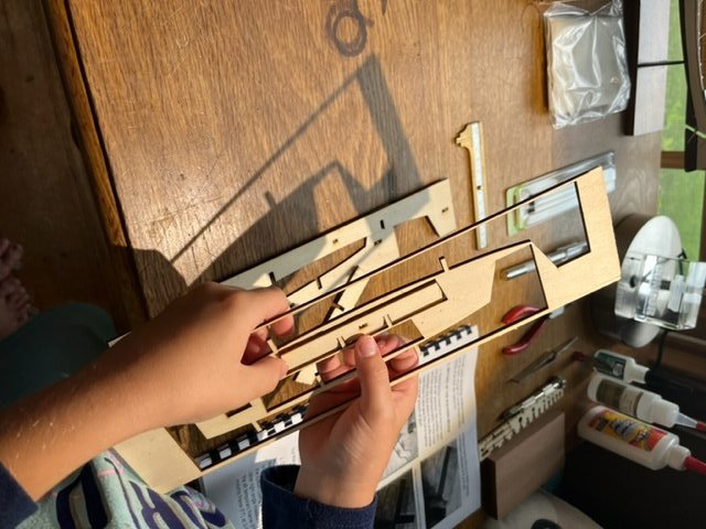
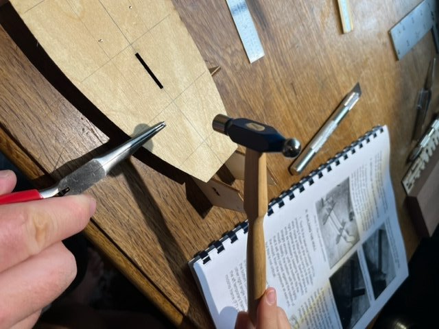
We started by separating the parts and assembling the hull mold frame. Then we assembled the hull mold frame: Got to do some math and geometry laying out the bulkhead locations on the hull floor: My daughter liked nailing the hull bottom down to the mold with pins. Then we glued together the transoms
- 33 replies
-
- 3
-
-
- Optimist Dinghy
- BlueJacket Shipcrafters
- (and 1 more)
-
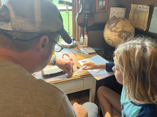
Groetjes Everyone! Well it's a rainy day today so, perfect time to work with the kiddo's on this project.
- 33 replies
-
- 2
-
-
- Optimist Dinghy
- BlueJacket Shipcrafters
- (and 1 more)
-
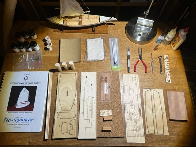
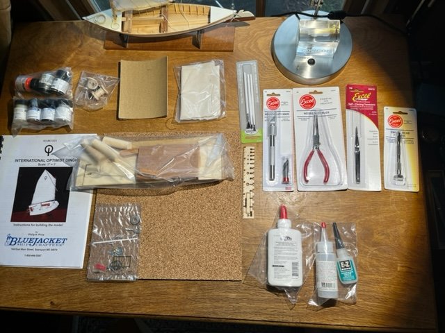
Here's all the components unpacked. I'm going to have a cheery ole time building this simple fun model. Jason
- 33 replies
-
- 2
-
-
- Optimist Dinghy
- BlueJacket Shipcrafters
- (and 1 more)
-
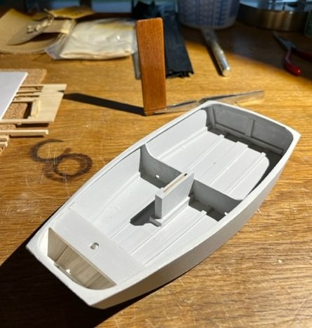
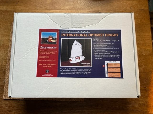
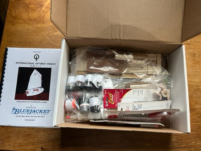
Ahoy Fellow Model Ship Builders!! Just purchased and received the Optimist kit from Bluejacket. I bought this as a model to build with my daughters, which I am looking forward to and I hope they enjoy it as well! Both of them sailed on Opti's so they have a connection to the boat. This is the first model I have built by BlueJacket and the kit has made a good first impression. The contents are well packaged contents, and as this is intended as a beginners first ship model, the kit includes a nice full size print drawing (not pictured) , glues, paints, pin-vise with drill bits, pliers, tweezers, razor knife, and all components needed for the build. Just opened up the box and I'm hoping to get started over the weekend. Cheers! Jason
- 33 replies
-
- 2
-
-
- Optimist Dinghy
- BlueJacket Shipcrafters
- (and 1 more)
-
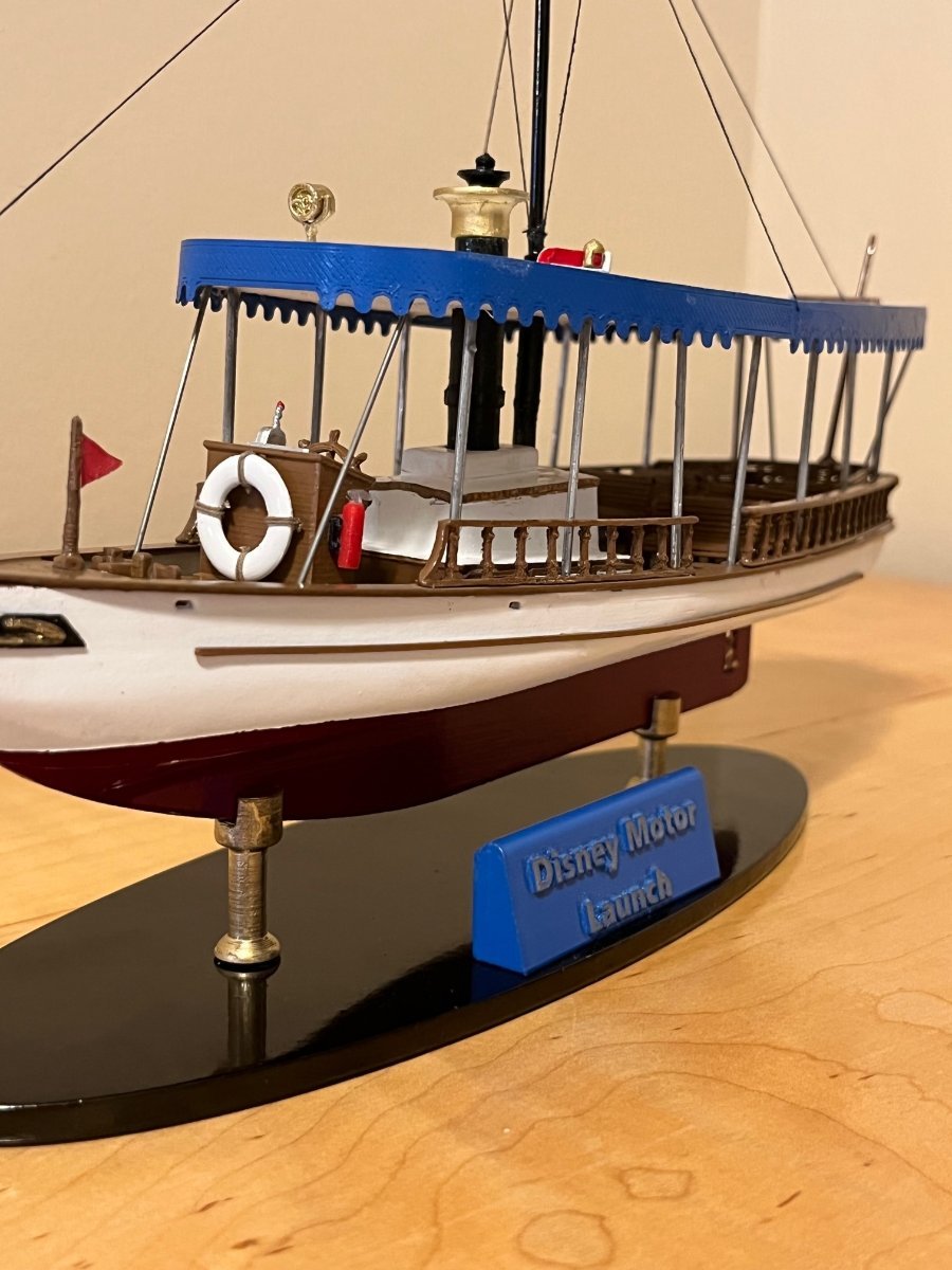
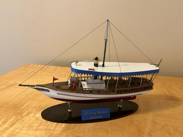
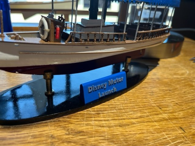
What a fun little project this has been. My first plastic model and first scratch built model. To finish off the model, I added steel rod braces fore and at between the roof and deck to match the actual boat. I then attached the mast and standing rigging. Happy modelling to you all! -Jason

-
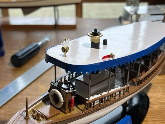
hi Everyone, Assembly is going well so far. I glued the awning around the roof and glued the roof to the roof poles. Installed the navigation lights and the spot light. Then glued on the rub rail. I changed the color of the base-plate to black, as it looked like too much brown earlier. I also installed the flag poles and life ring.
-
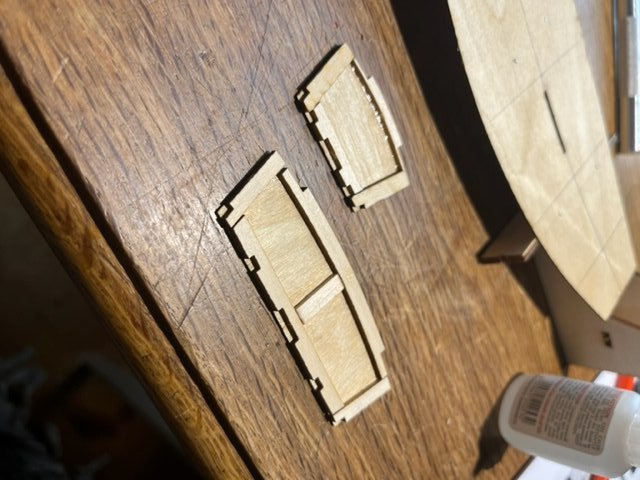
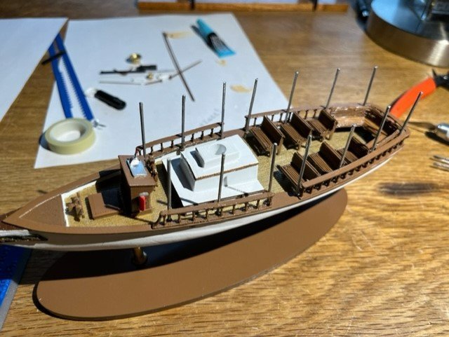
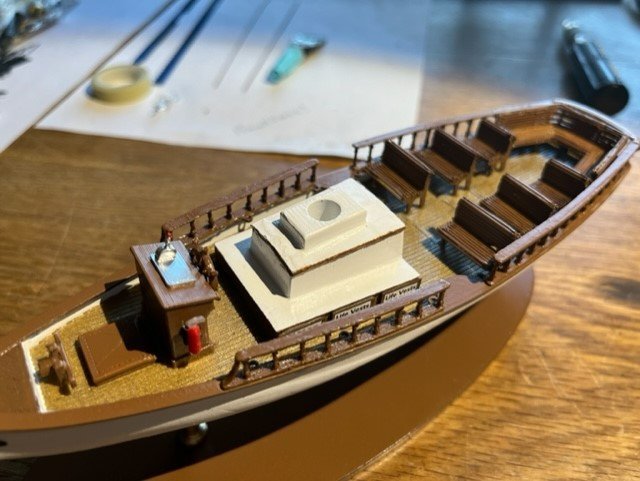
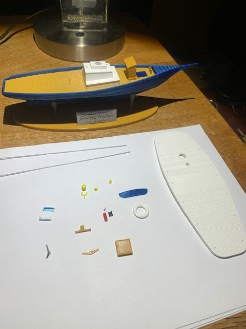
Guten Abend, So today with painting wrapping up, I got to assembly. Glued the life vest hatches onto the engine house sides, glued the deck on and the fore-hatch, and the fire extinguisher, ships wheel, coaming cap, railings, benches, and I set the roof poles in place. Have a great day! Jason


-
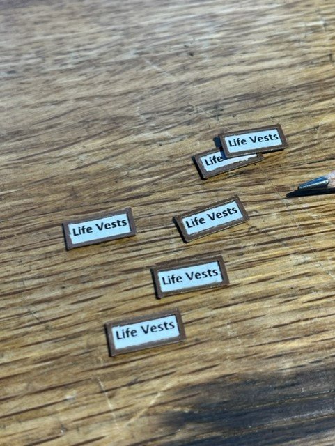
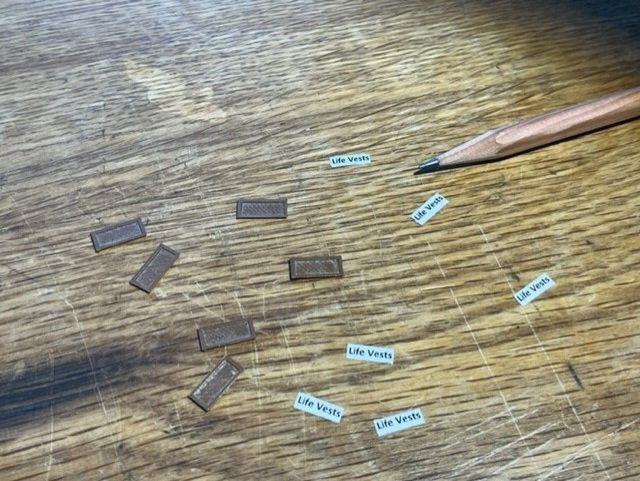
Hi Everyone, Painting, sanding, painting..... I also saw that there are life vest hatches that I had missed in my design so I designed/printed those and then printed the text on my paper printer and glued the text to the hatches. -Jason

-
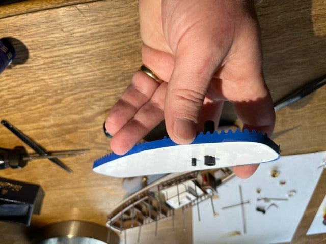
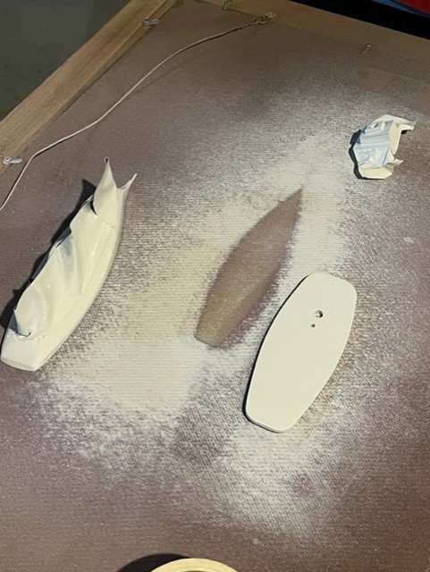
Merhaba, Model Boat Builders! Tonight I got around to some sanding and painting. Also, during design, I noticed that I had a square stern, but the boat should have a rounded stern. I had already printed my hull, so I printed a stern filler piece to round out the stern. I designed the roof as a laminated structure with a thin smooth sheet laminated on top of the thicker curved roof piece, saved me some sanding time.
-
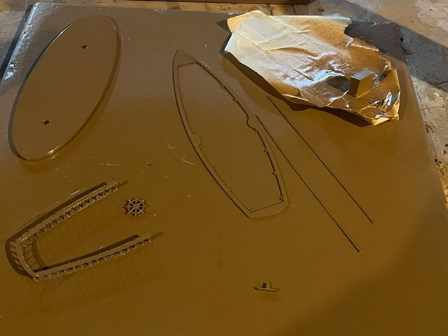
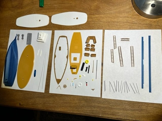
Сайн уу, Mongolian spelling of "hello" there. Visited there multiple times for fun and work and it's a great place. So now I have printed all the part for the model. After working through the best print orientations for the parts, I wound up splitting the railings into multiple parts, so the model has 69 printed parts shown here, (edit: plus the 6 life vest hatches shown in the post further below) for a total of 75 printed parts, which I will now sand/paint/assemble. -Jason
-
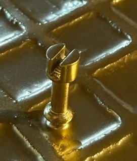
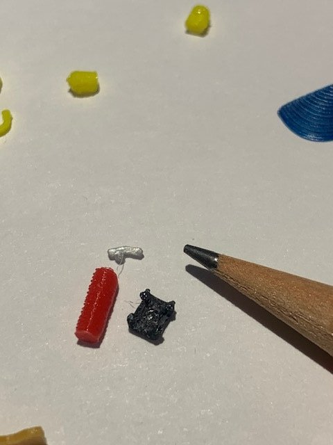
Hallo allir! Well the design work is done in CAD and now I need to keep printing away. I am going to print all the parts (and check fit as I go) before I begin final assembly. I have designed the model with 62 separate printed parts + 5 metal eyelets + 2 fabric flags + standing rigging. The fire extinguisher canister/handle and bracket are pretty small, but I am pleased with the as-printed parts.......the parts will be sanded/assembled/painted (not always in that order). -Jason
-
Hi! Thank you for the detail on how to draw the propeller. Congrats again on the model. -Jason
-
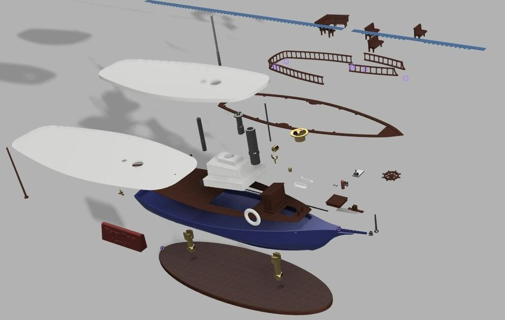
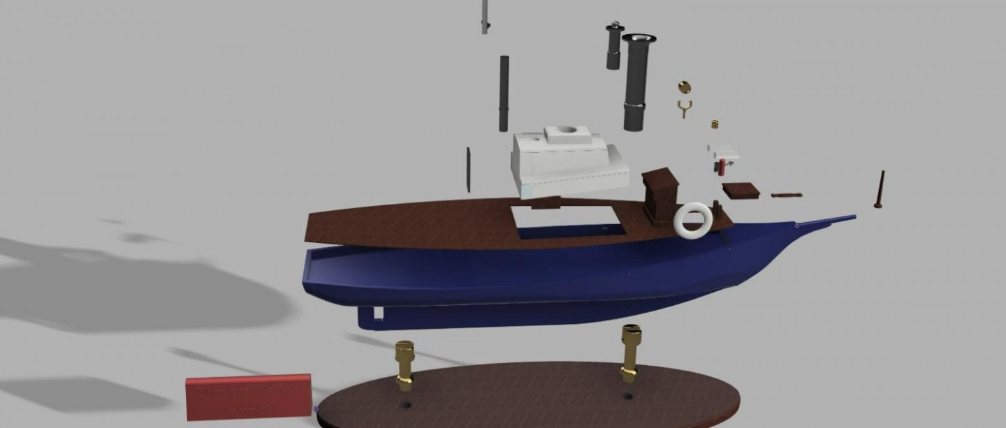
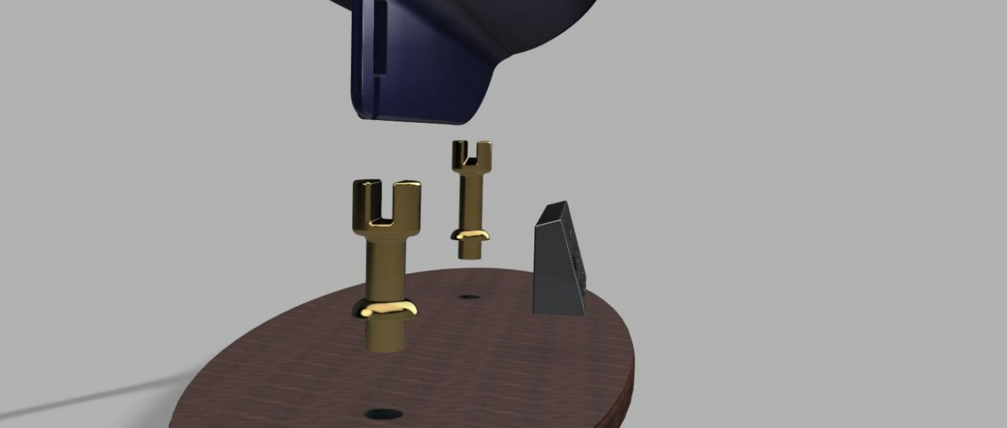
Hi Everyone, Not much work on the model this week but was able to get the deck printed, I designed it to be thin and it is very flexible to flex along the required curvature. Planking printed right onto the deck along with the helm stand and the cross-bollard posts. I am also pleased with the resolution of printing at the .05mm layer thickness with the very small parts. I'll post a picture of the rendered parts; all I have left to design is the prop , awning/roof trim, and the railing. Cheers! -Jason


-
hi Arctic37, I am just starting my first attempt at designing and making a 3D printed boat model, so was happy to see your build log of a 3D printed ship model. Your 3D CAD skills are fantastic. I am teaching myself the 3D CAD as I go, which has been fun. I struggled with the hull and I don't think I could draw a curved propeller like that, nice work! What make and model of printers to you use? Looks like the hull was printed in 3 sections is that right? My Prusa i3MK3S has a 210mmx250mm print bed (8.3" x 9.8"). Thanks for sharing your build-log, congrats on the model.
-
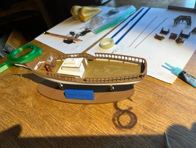
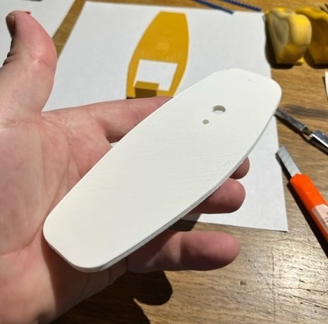
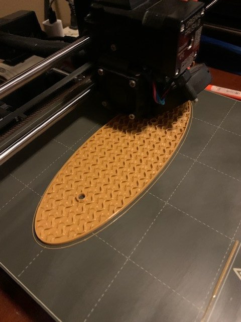
Bonjour, Yesterday I kept on drafting away on CAD. I printed the stand for the model so that I had somewhere to set the hull. Good news, my sharp file worked very well to put the finish shape to the hull in the spots I couldn't get just right on CAD. I still think a high speed sanding or grinding device would just melt the plastic rather than removing material, but so far so good using handwork for filing/sanding. I have enough pieces designed that I will be able to keep the printer busy while I continue to draw. The keel-holders on my model stand were printed with 50% infill and are quite sturdy. The base was printed with 10% infill (in-progress photo below). I am using up filament so the parts will be printed in somewhat random colors, but will be painted later. Have a great day,

-
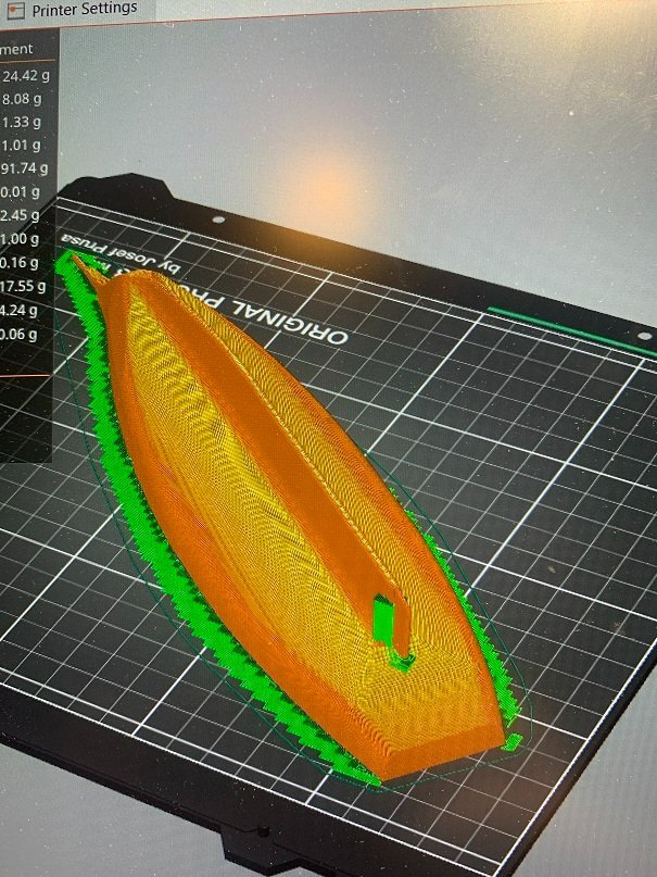
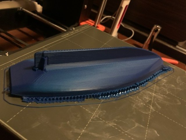
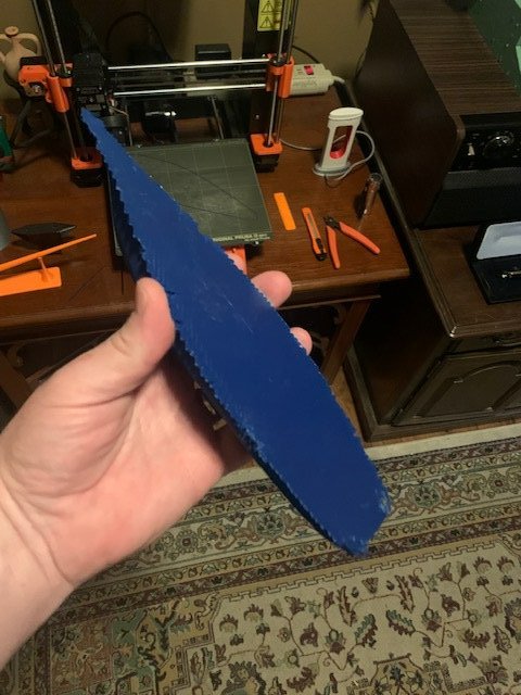
Goede Dag! Well I printed the hull overnight and it turned out OK. I set the printer at .20 resolution with 10% infill and 6mm wall thickness, so the walls are pretty thick to allow for final sanding and shaping (which hopefully is possible with this material...) I printed upside down and it took about 9.5 hours to print. Much finer resolutions are possible, but would extend print time and I will be sanding this part anyway. I use Prusaslicer for my slicer software and I printed this hull upside down with the automatically generated support material to fill the void between the print plate and the model. Here are the photos of the printed hull and the support material that I removed with small pliers and snips. I am not a 3D printing expert, but if anyone is interested in a veeerrryyy basic intro to 3D printing, I typed up a page on how I got started, here : https://www.argobuilder.com/3d-print-workshop.html -Jason


-
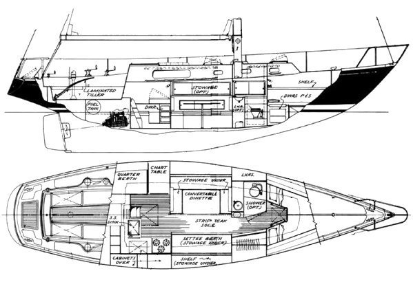
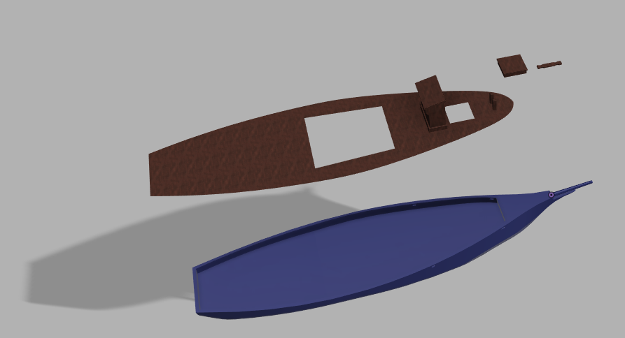
Hi! I found a basic drawing of the Morgan 41 hull, and I used that along with photos of the launch to create a 3D hull drawing. I graduated from Milwaukee School of Engineering in the '90s, but at the time 2D CAD was a very insignificant part of the engineering degree; I hadn't used CAD for 20 years and never used 3D CAD before, but I have really enjoyed learning Fusion 360 (I think it's been good for the brain), but I am no expert. I am learning as I go. I was able to get a decent roughed out shape of the hull, but I will need to file and sand it to finished shape. I will print this in PLA (Polylactide), and I am not sure if that material is sand-able or file-able, we will find out. If it is not, then I will need to go back to the drawing board and put more time into a perfect hull drawing. I have also completed the model of basic deck. I will print this in a very thin sheet and glue it onto the hull. I drew the planks into the surface of the deck and hopefully the printer has good enough resolution to print the little grooves between the planks. I plan to print the helm and the bollard posts right onto the deck when I print it. -Jason
-
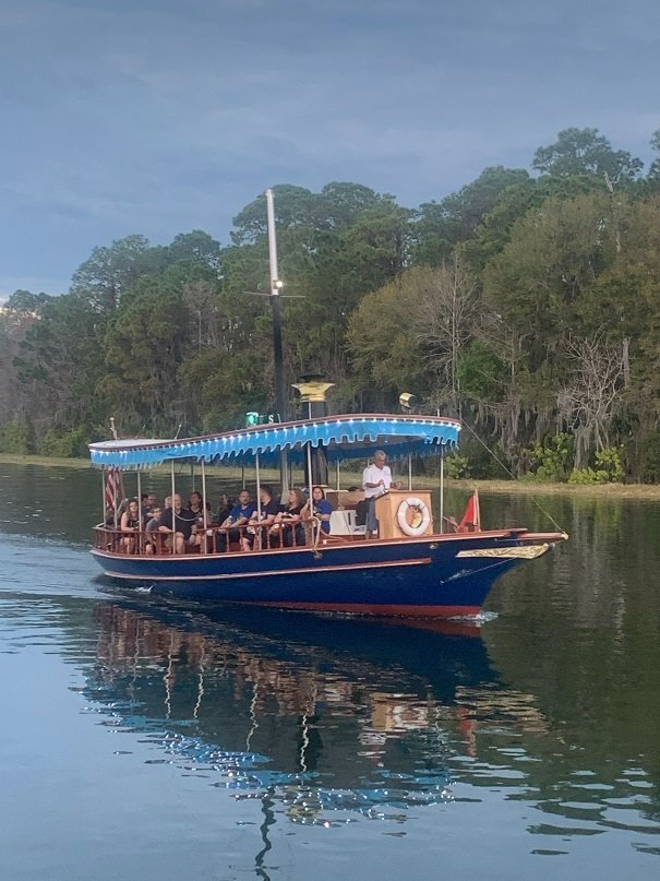
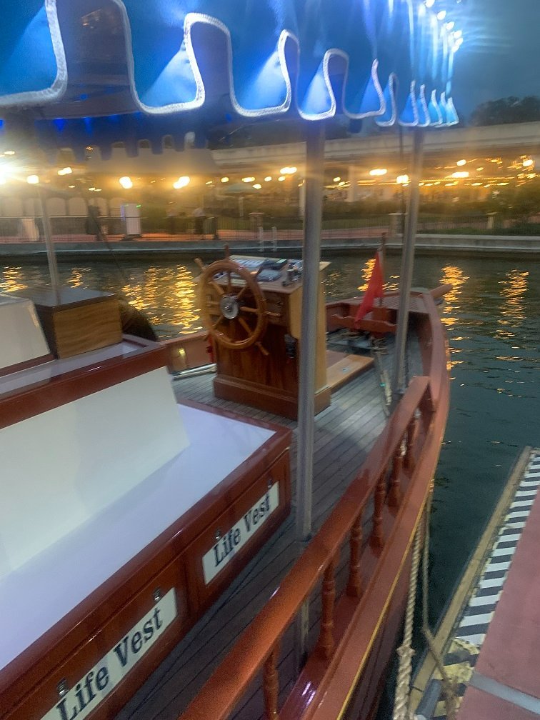
Ahoy Modelers! It's been a couple years since I built a model boat or ship and I have never built a ship model from scratch and I feel that it is time for a new model ship project. I always have to be building something, and in the two years away from model boat building, I have scratch built a full size functional alphorn, 2 Viking Lurs, a wooden paddleboard, and have been making homemade brooms. In 2020 I assembled a Prusa i3 MK3S 3D printer and got Autodesk Fusion 360 CAD. The kids and I have had a great time designing and printing objects both fun and practical on the printer since we got it. Last week we took a family trip to Disney World in Florida, and I really liked the little "Motor Launches" that ply the waters of Bay Lake and Seven Seas Lagoon ferrying people between the resorts and Magic Kingdom. That is the boat that I have decided to build a model of, and I will document my attempt here. I spoke to the captain of one of these boats, who advised that the boat is approximately 41.5 feet long with a draft of 3.5 feet and is based on a Morgan 41 sailboat hull. Morgan built these in Clearwater FL, out of fiberglass with a modified keel and bowsprit. The boat has a fixed shaft and prop and traditional rudder. They were made in the style of a steam launch, but the stack is just for looks, these are not steam-powered vessels; they have a nice little motor in them, and the captains are very adept at docking them and casting off like pro's every time. I will do my best to draw this boat in Fusion 360 and to print the parts on my Prusa i3 MK3S printer. I do not have good experience with plastic models, but I plan to superglue the parts together and to enamel the model. Here is the printer and a picture I took last week of the boat. -Jason