
Sizzolo
-
Posts
190 -
Joined
-
Last visited
Recent Profile Visitors


-
 Stavanger reacted to a post in a topic:
Bower anchor project by Sizzolo
Stavanger reacted to a post in a topic:
Bower anchor project by Sizzolo
-
Stavanger reacted to a post in a topic:
Bower anchor project by Sizzolo
-
Mike Y reacted to a post in a topic:
Copper plate overlapping (< > 1794) - lower overlaps upper or vice versa?
-
KARAVOKIRIS reacted to a post in a topic:
Bower anchor project by Sizzolo
-
Thukydides reacted to a post in a topic:
Bower anchor project by Sizzolo
-
Tumblehome reacted to a post in a topic:
Bower anchor project by Sizzolo
-
Kenchington reacted to a post in a topic:
Bower anchor project by Sizzolo
-
Kenchington reacted to a post in a topic:
Bower anchor project by Sizzolo
-

Bower anchor project by Sizzolo
Sizzolo replied to Sizzolo's topic in - Build logs for subjects built 1751 - 1800
Forgot say; the amount of serving above the buoy knot on the buoy rope turned out to be the perfect length to support the wrapping around the bower anchor. It’s nice when the theory matches the practical - v rewarding for model makers. Happy new year all. -
Bower anchor project by Sizzolo
Sizzolo replied to Sizzolo's topic in - Build logs for subjects built 1751 - 1800
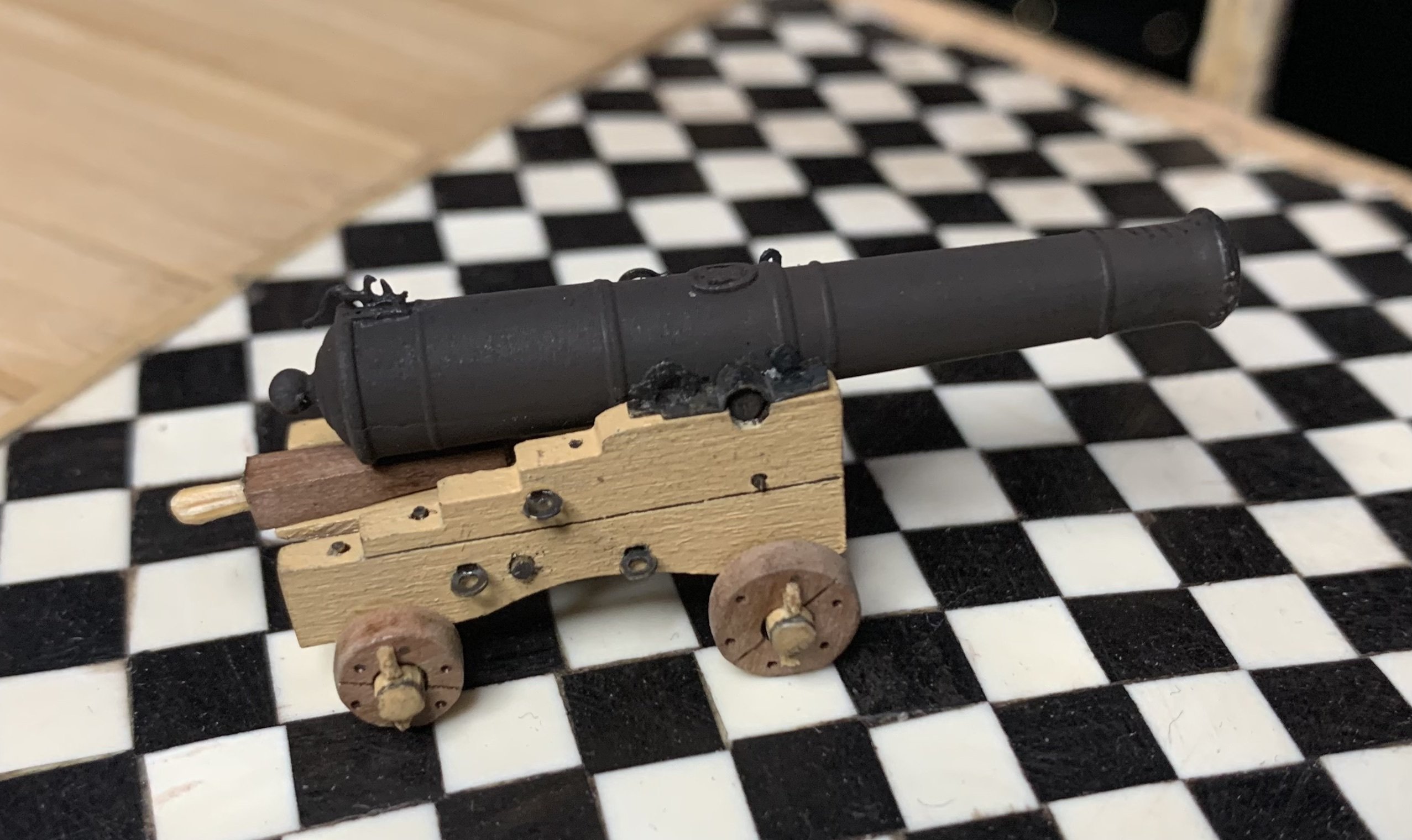
Last quick pics of the project this year. As you can see the figures aren’t finished yet - just started painting. The kedge anchor is fun but I’ll probably need my mate (professional jeweller) to affix the arms as they’re currently just glued and I can’t generate a good silver solder joint with my own limited skills/equipment. It was fun to make and easy to file. I doubt it’ll be used in the final display though. Who knows. The buoy rope needs binding to the bower and then the ‘bower anchor’ part is complete and I’ll stop this thread.


-
cotrecerf reacted to a post in a topic:
Bower anchor project by Sizzolo
-
cotrecerf reacted to a post in a topic:
Bower anchor project by Sizzolo
-
Bower anchor project by Sizzolo
Sizzolo replied to Sizzolo's topic in - Build logs for subjects built 1751 - 1800
It’s definitely a plastic. I was forced to go back to the pub to get a sample, and have a couple of pints of course. It sounds like I might need to do some research at the National Archives on plaited rope. It’s always nice to nip in there. Cheers for the info on the extra coloured thread - good to know! -
Bower anchor project by Sizzolo
Sizzolo replied to Sizzolo's topic in - Build logs for subjects built 1751 - 1800
Drat. Bit confused why a modern rope would have that white strand though. Maybe it’s a modern ish RN and the white strand rule is still in place? There is a marines training base over the river. Pretty sure it’s man-made fibre btw. I guess it’d be obvious if I tried lighting the end to see if it melts? -
Bower anchor project by Sizzolo
Sizzolo replied to Sizzolo's topic in - Build logs for subjects built 1751 - 1800
Tbh it felt a bit nylonny. I’d does provide me with a better idea of the plaiting method and how the white thread was laid however.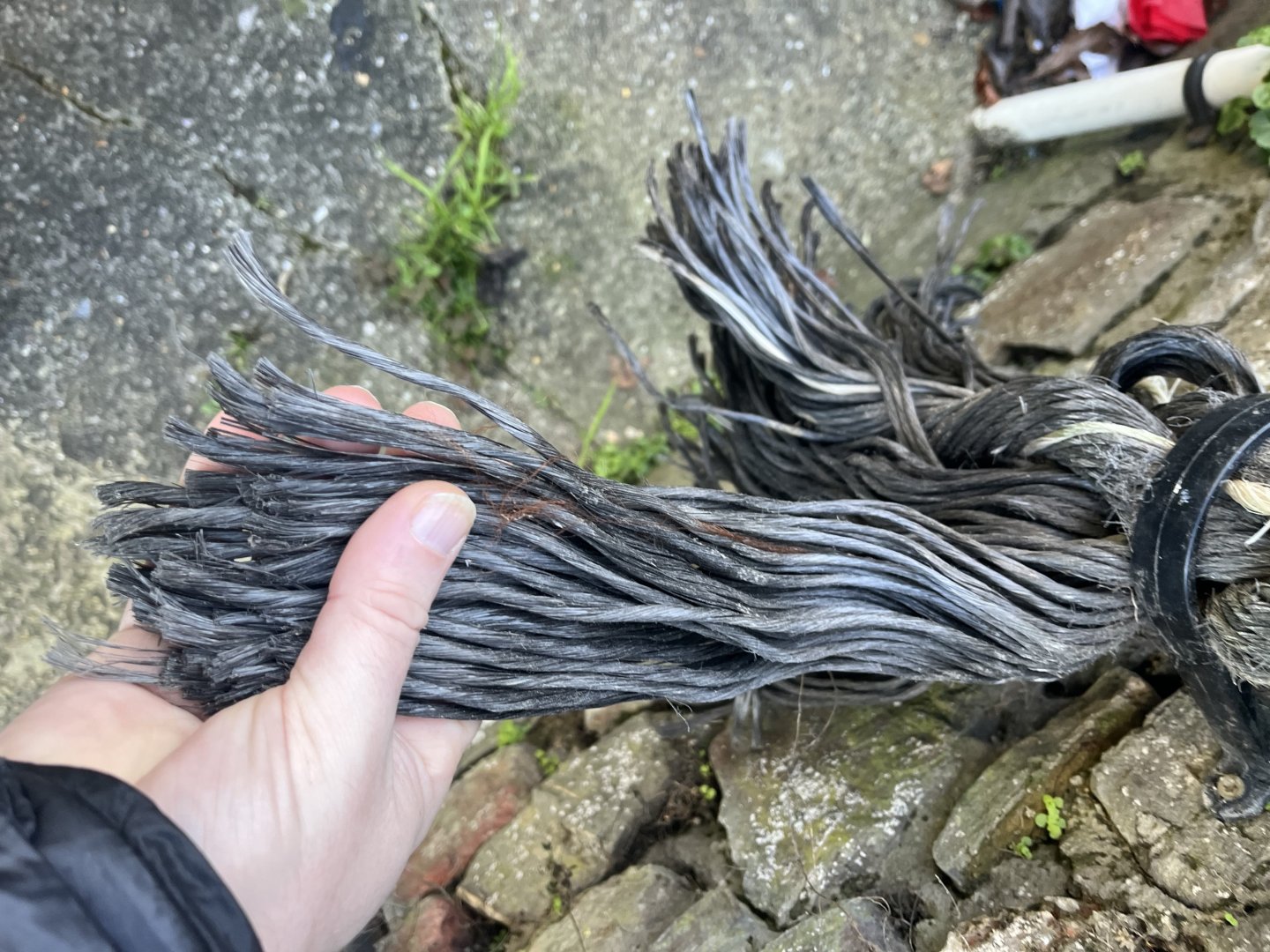
-
Bower anchor project by Sizzolo
Sizzolo replied to Sizzolo's topic in - Build logs for subjects built 1751 - 1800
47 threads in each strand, including the white one. -
Bower anchor project by Sizzolo
Sizzolo replied to Sizzolo's topic in - Build logs for subjects built 1751 - 1800
Steel: “A white thread, twisted the contrary way, is to be laid in all the strands of the cables and large cordage; and a twine in the small cordage for the king’s mark, so as to be seen on the outside of the strands.” ”Mooring services are clapped on about fifteen fathoms from the end or cable splice. Large vessels should have twelve or fourteen fathoms of service, half of it rounded and the rest plaited and keckled. Upon the best bower or working cable, there should be a short service of eight or ten fathoms at the half-cable.” -
Bower anchor project by Sizzolo
Sizzolo replied to Sizzolo's topic in - Build logs for subjects built 1751 - 1800
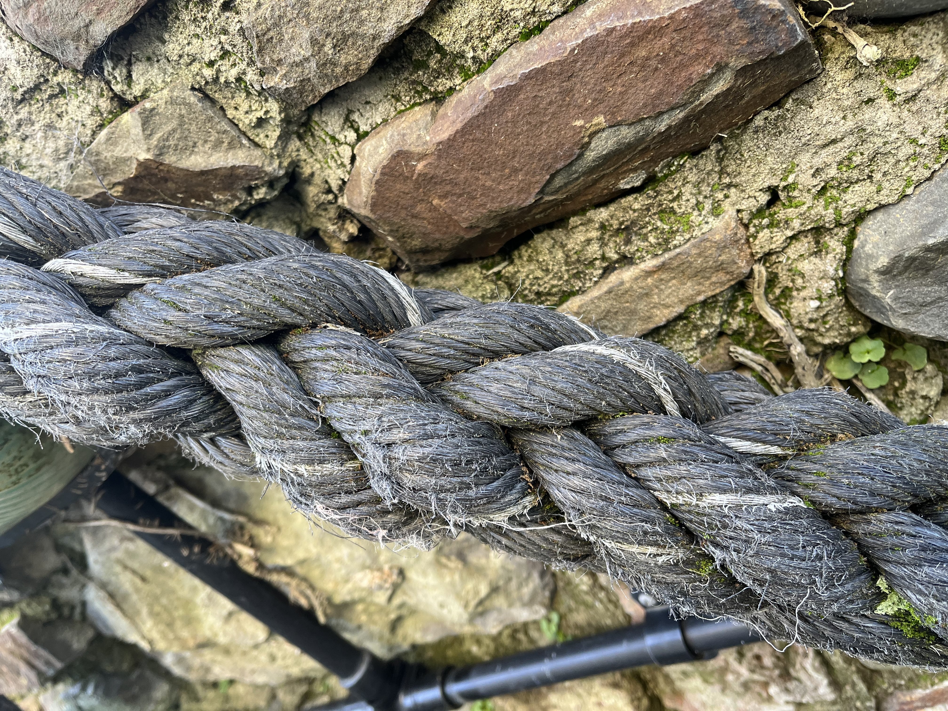
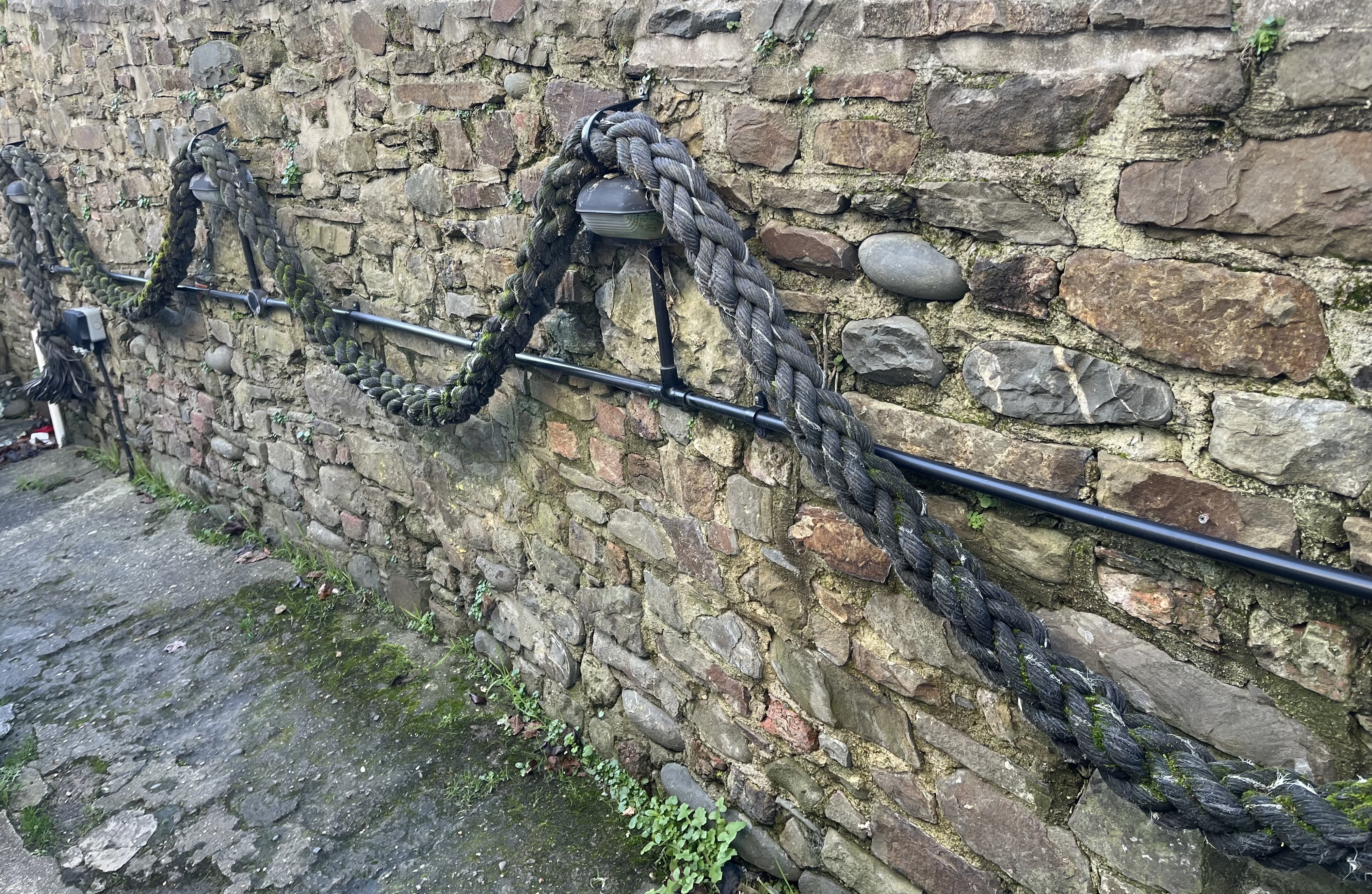
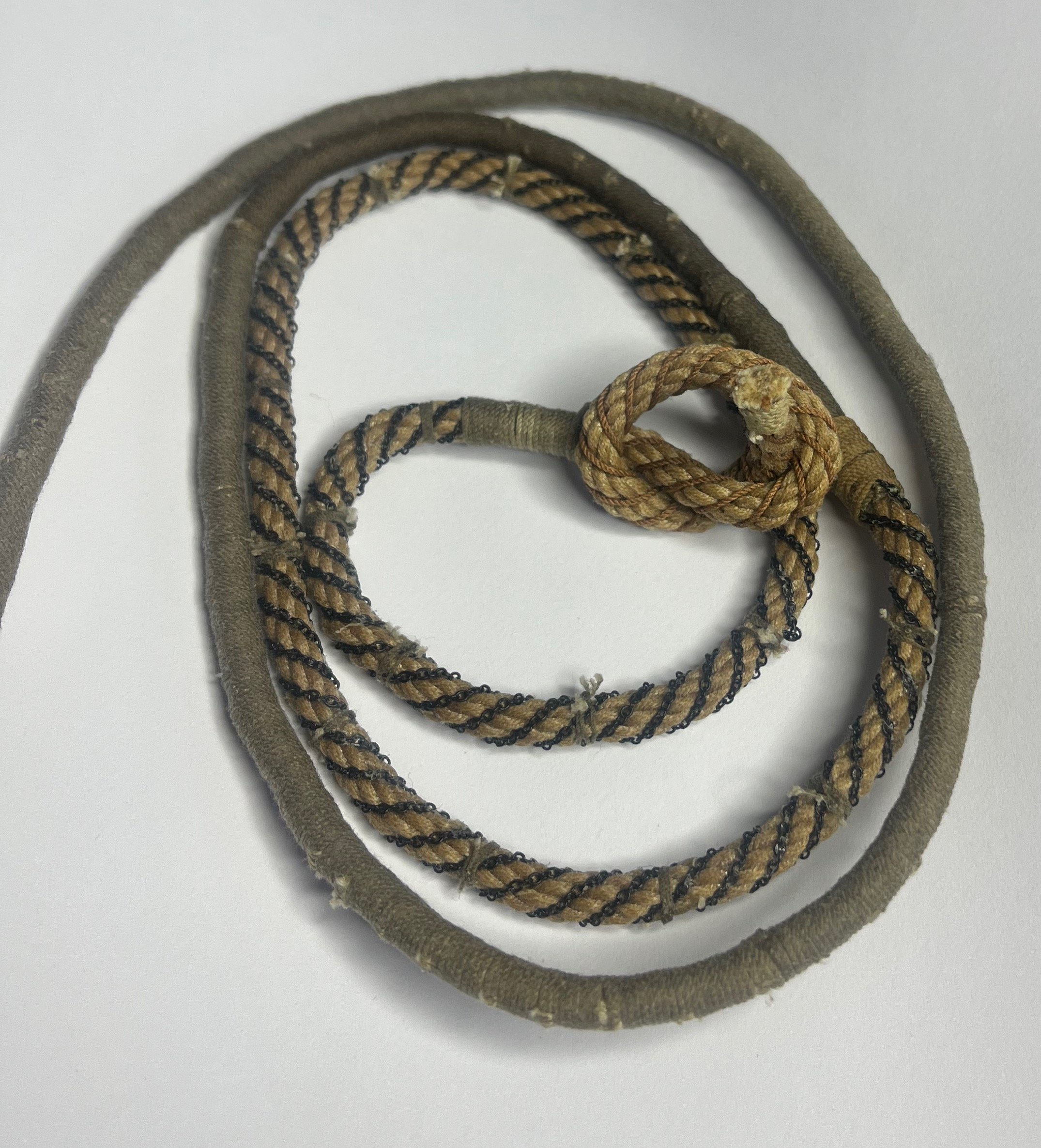
Hi all! Just to let you know I haven’t stopped! Kedge anchor parts done so they just need silver-soldering (which I’ll do outside to avoid burning my flat down). Briefly thought of you all just now as, during my research in to cable laid rope I kept finding historical reference to ‘plaited’. Look what I found outside the pub I’m in: Plus - it has that white thread which I saw reference to meaning it’s RN rope/cable. I always wondered how this would look and even tried a few (failed) tests. Another added benefit of the example is it clearly shows the colour difference of white vs tarred. I’ll try and take a pic of the end when I leave so we can see the thread-count. (I just spotted - note the pairs of strands are made in opposite directions - with the sun and against - good to know if you’re going to make some).

-
Bower anchor project by Sizzolo
Sizzolo replied to Sizzolo's topic in - Build logs for subjects built 1751 - 1800
Sorry for lack of updates. I’ve been painting the two sailors (helps to add scale to the final pics). Also decided to make the kedge anchor from the original source plan as it might be part of the final model (which will include the kedge anchor cable). I’m making it from brass and it’s surprisingly satisfying just using files. The original bower anchor was going to be brass until I realised how massive and heavy it’d be (hence using 3d printing for that). -
Bower anchor project by Sizzolo
Sizzolo replied to Sizzolo's topic in - Build logs for subjects built 1751 - 1800
Link-worming complete. The Cable is pretty much complete but I'll tidy it up a bit when it's laid in the longboat and bent to the anchor ring. I could have probably done the model without serving all that length of cable and just doing link-worming but it was a good experience and more representative of how a working RN cable may have appeared. As previously stated, a primary objective was to build a working ropewalk and get familiar with its operation. It took almost half a kilometre of thread but I made some progress!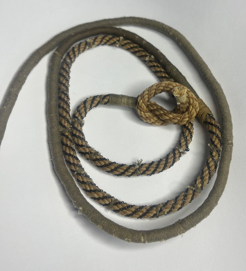
-
Bower anchor project by Sizzolo
Sizzolo replied to Sizzolo's topic in - Build logs for subjects built 1751 - 1800
Brief update; Almost done joining the cables and doing the link-worming. Stats: Total length of thread used: 190 meters of thread for Serving/rounding on the cable, 30 meters of thread for Worm on the cable that nobody will see, 176 meters of thread for the cable Total: 396 meters. (at least another 4 meters for seizing...so <> 0.4km of thread) -
Bower anchor project by Sizzolo
Sizzolo replied to Sizzolo's topic in - Build logs for subjects built 1751 - 1800
pics of the served cable and original anchor bend (which is nicely similar to the earlier pic of his victory now).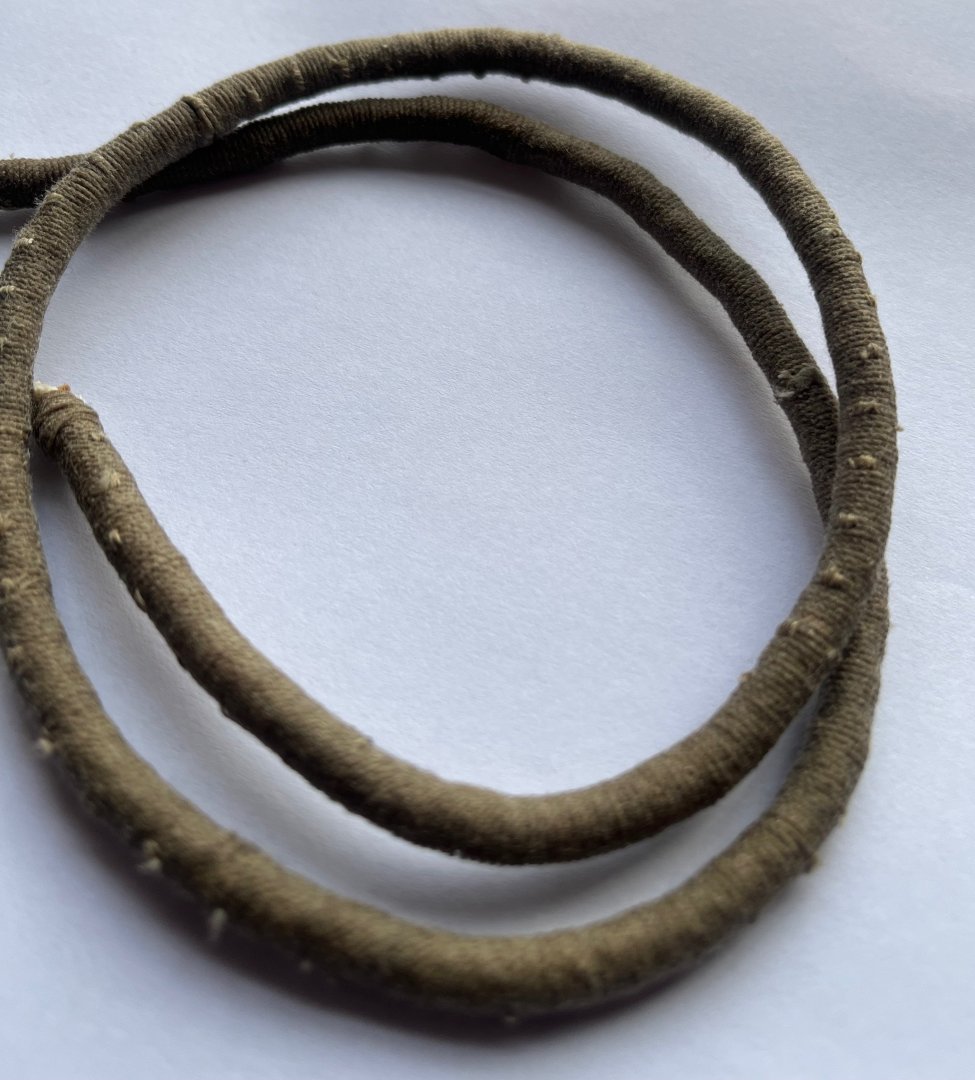

-
Bower anchor project by Sizzolo
Sizzolo replied to Sizzolo's topic in - Build logs for subjects built 1751 - 1800
Well this is quite frustrating... I've discovered (after trying for a few hours) that there is absolutely no way that chain was applied over served cable. It's impossible to bind it to the cable as it requires the valley (contline) of the cable to be able to get purchase. After that it's possible to bind it at points along the cable. There's also no documentary evidence to say it was applied over served cable as far as I can tell. Rather than ripping off all the meters of serving which took days to do, I'll knock up an extra length of cable and splice it between the current cable and anchor. On this additional length I'll apply the chain. It doesn't change the design of the model I'm planning much as I'll just have more of it coiled in the longboat. The cable splice should be interesting! V annoying though but at least I've learned something by trying to practically reproduce this blooming thing from literary evidence. -
Bower anchor project by Sizzolo
Sizzolo replied to Sizzolo's topic in - Build logs for subjects built 1751 - 1800
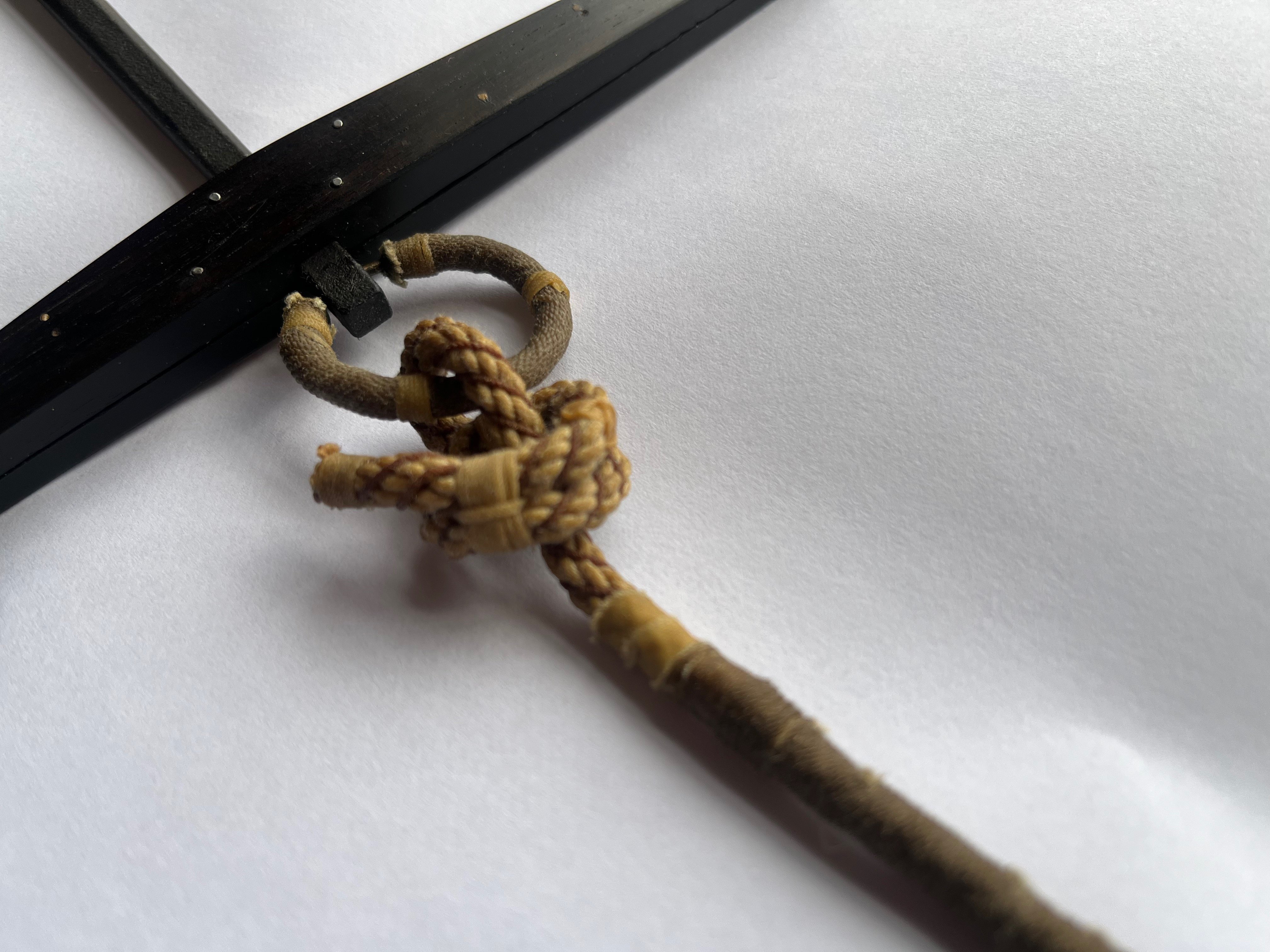
Just a text update today as I’ve already got to the pub. Last steps are actually - worming and parceling 3 fathoms above the buoy-rope knot done Final details on anchor (some weathering powders) another 25cm of serving on the anchor cable (soooo boring) done Worm chains to anchor cable bind chains every 2cm or so Paint two sailors who will be working on the ropes Transition to build the longboat Assemble pieces and build case go to pub. -
Bower anchor project by Sizzolo
Sizzolo replied to Sizzolo's topic in - Build logs for subjects built 1751 - 1800
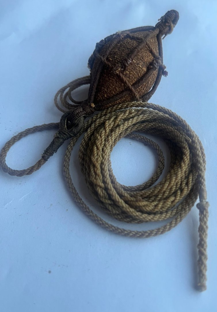
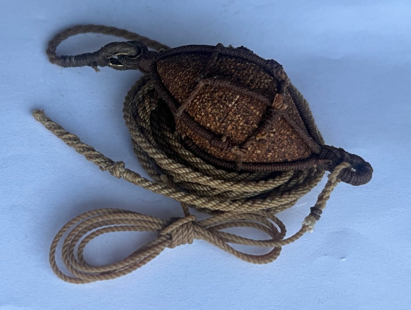
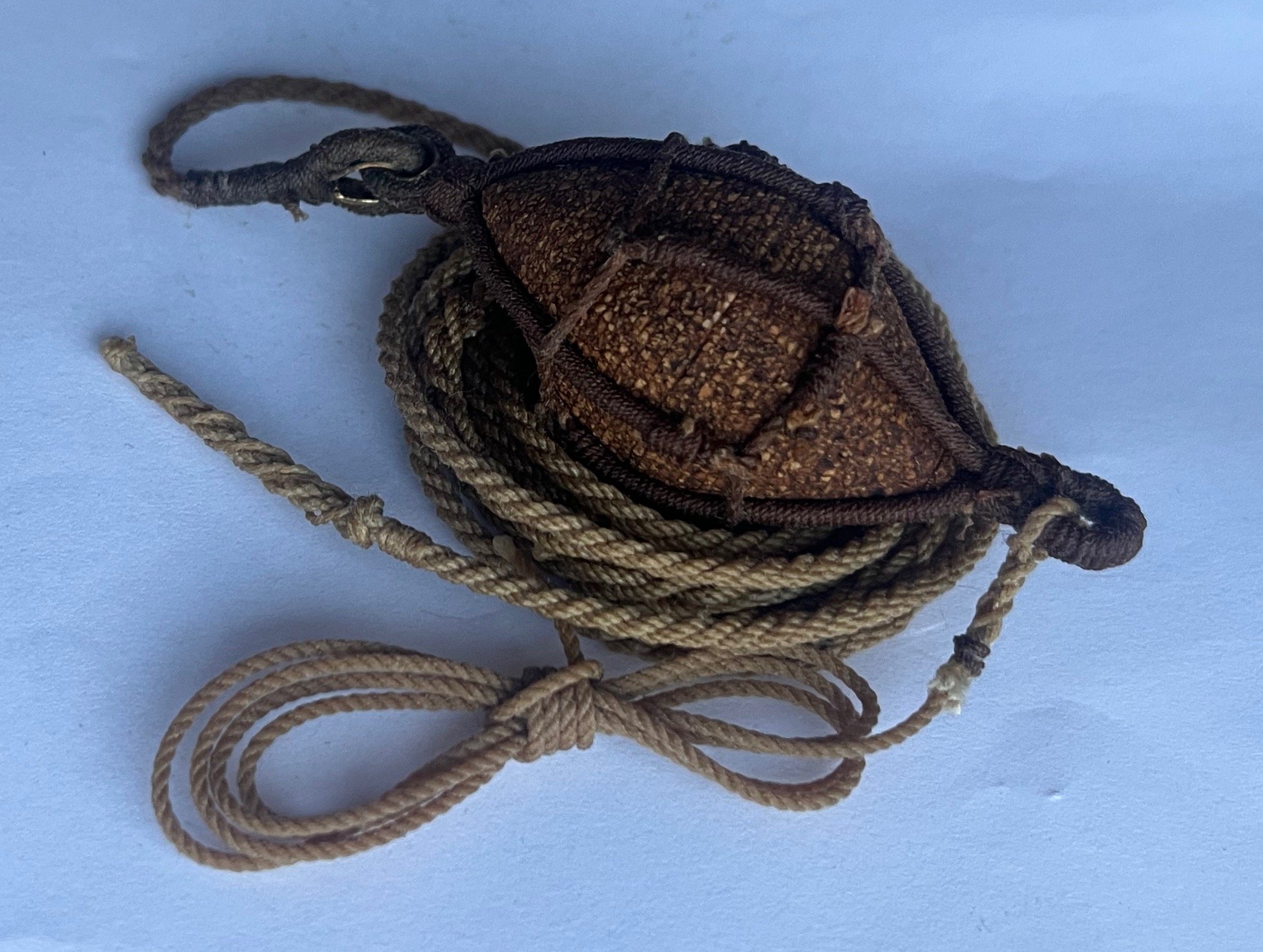
Buoy done. I used eye splices for both ends as there were too many variables to make a decision on the 'bend'. Buoy rope has two long splices now and a re-done double-wall knot. All ropes painted with 25% Stockholm tar, 75% boiled linseed oil. Next step - bit of tidy up work on the anchor and attach the buoy. I'll probably generate a new topic for the longboat that this lot is going to play a part in.