
Sizzolo
-
Posts
182 -
Joined
-
Last visited
Content Type
Profiles
Forums
Gallery
Events
Everything posted by Sizzolo
-

Bower anchor project by Sizzolo
Sizzolo replied to Sizzolo's topic in - Build logs for subjects built 1751 - 1800
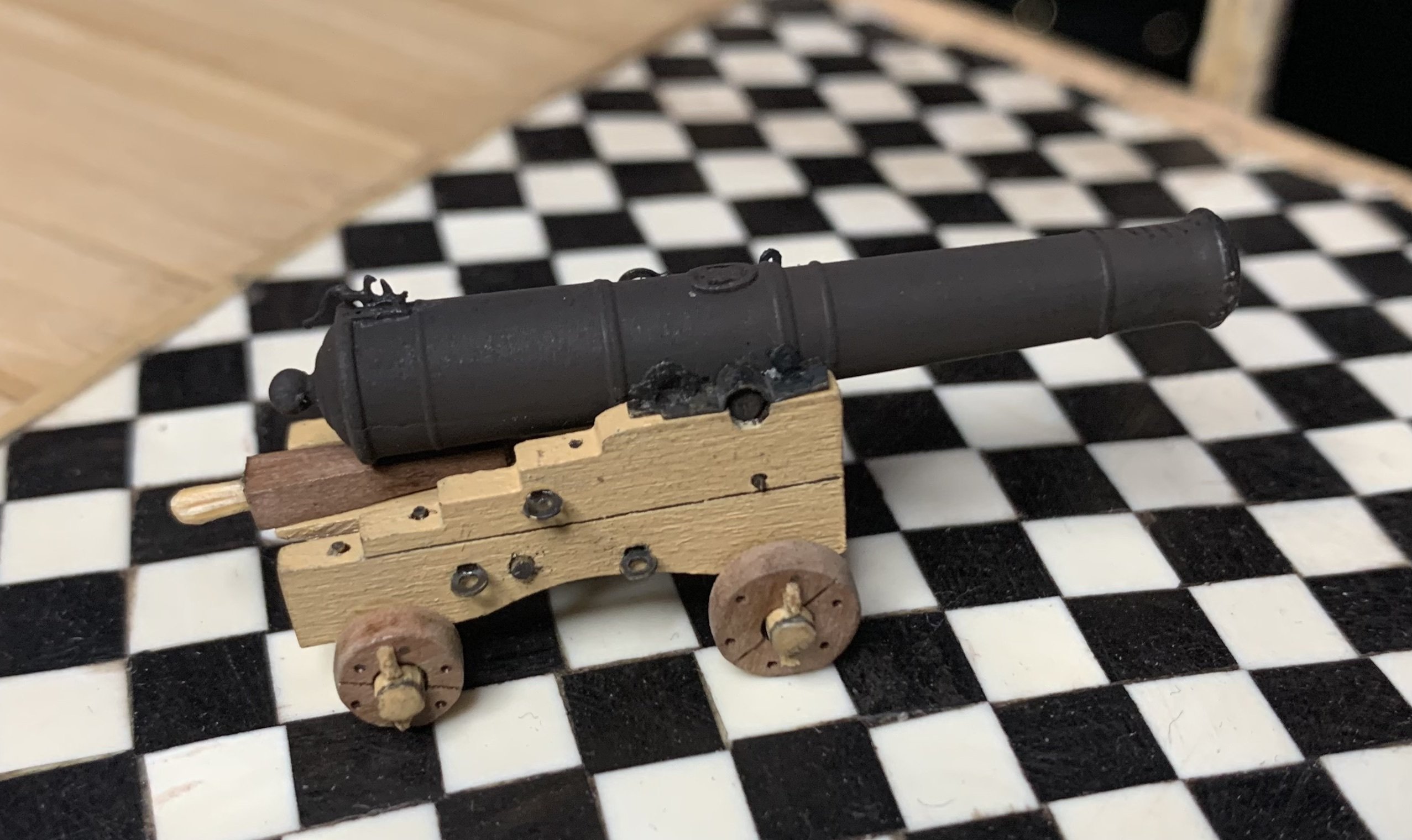
Sorry for lack of updates. I’ve been painting the two sailors (helps to add scale to the final pics). Also decided to make the kedge anchor from the original source plan as it might be part of the final model (which will include the kedge anchor cable). I’m making it from brass and it’s surprisingly satisfying just using files. The original bower anchor was going to be brass until I realised how massive and heavy it’d be (hence using 3d printing for that). -
Bower anchor project by Sizzolo
Sizzolo replied to Sizzolo's topic in - Build logs for subjects built 1751 - 1800
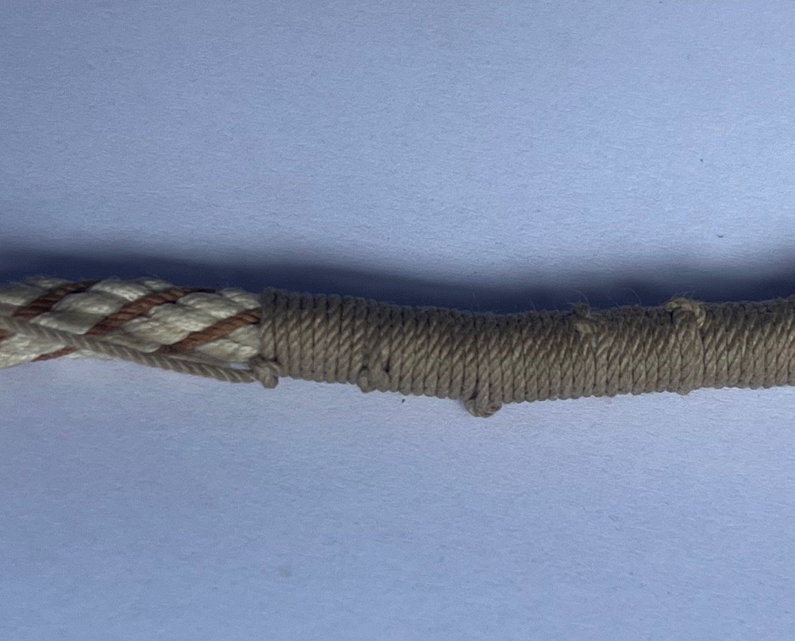
Link-worming complete. The Cable is pretty much complete but I'll tidy it up a bit when it's laid in the longboat and bent to the anchor ring. I could have probably done the model without serving all that length of cable and just doing link-worming but it was a good experience and more representative of how a working RN cable may have appeared. As previously stated, a primary objective was to build a working ropewalk and get familiar with its operation. It took almost half a kilometre of thread but I made some progress!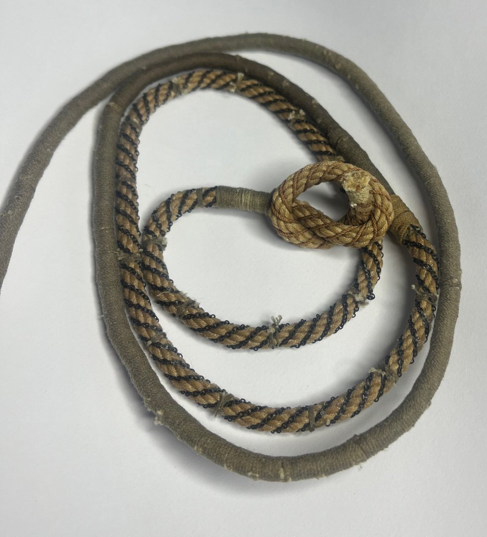
-
Bower anchor project by Sizzolo
Sizzolo replied to Sizzolo's topic in - Build logs for subjects built 1751 - 1800
Brief update; Almost done joining the cables and doing the link-worming. Stats: Total length of thread used: 190 meters of thread for Serving/rounding on the cable, 30 meters of thread for Worm on the cable that nobody will see, 176 meters of thread for the cable Total: 396 meters. (at least another 4 meters for seizing...so <> 0.4km of thread) -
Bower anchor project by Sizzolo
Sizzolo replied to Sizzolo's topic in - Build logs for subjects built 1751 - 1800
pics of the served cable and original anchor bend (which is nicely similar to the earlier pic of his victory now).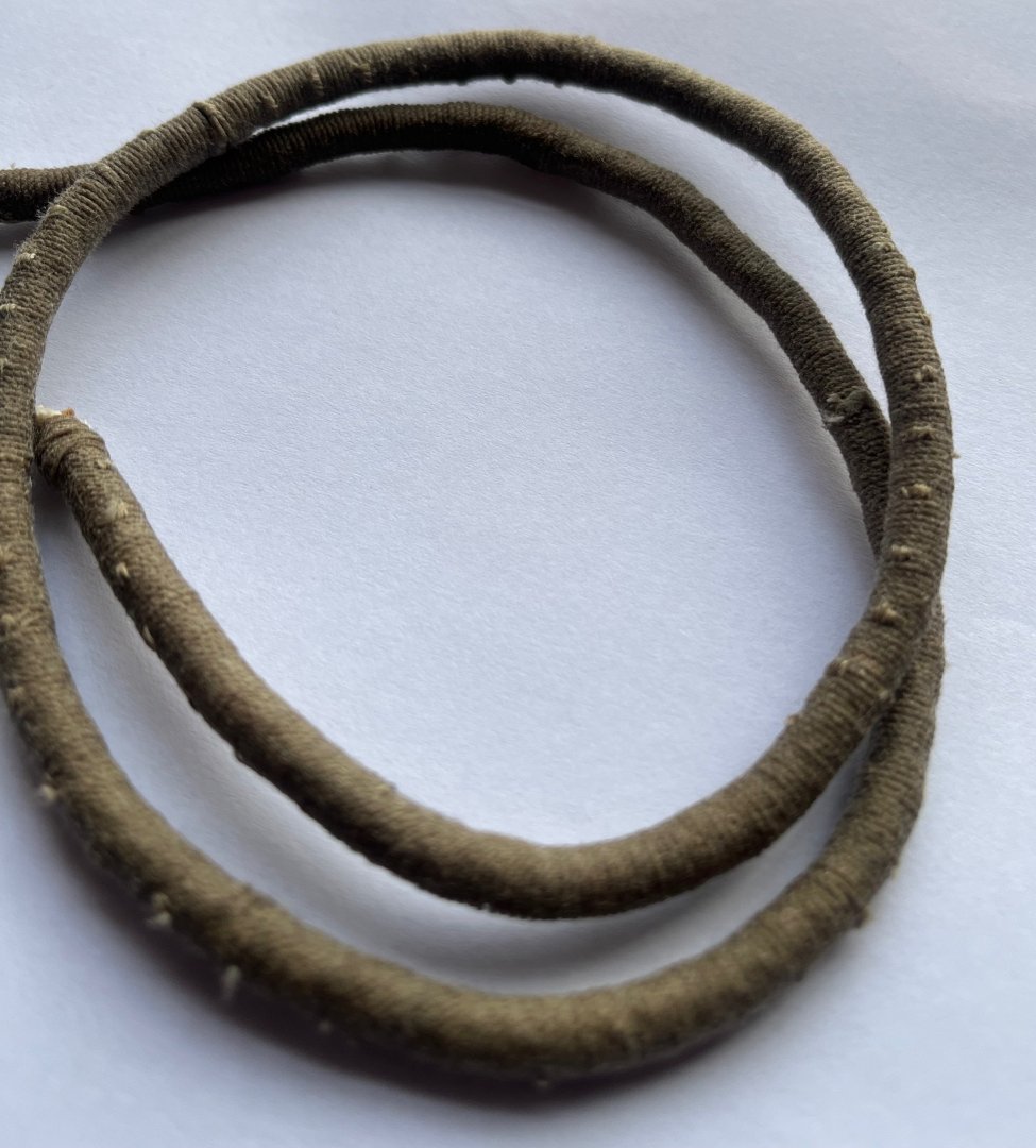

-
Bower anchor project by Sizzolo
Sizzolo replied to Sizzolo's topic in - Build logs for subjects built 1751 - 1800
Well this is quite frustrating... I've discovered (after trying for a few hours) that there is absolutely no way that chain was applied over served cable. It's impossible to bind it to the cable as it requires the valley (contline) of the cable to be able to get purchase. After that it's possible to bind it at points along the cable. There's also no documentary evidence to say it was applied over served cable as far as I can tell. Rather than ripping off all the meters of serving which took days to do, I'll knock up an extra length of cable and splice it between the current cable and anchor. On this additional length I'll apply the chain. It doesn't change the design of the model I'm planning much as I'll just have more of it coiled in the longboat. The cable splice should be interesting! V annoying though but at least I've learned something by trying to practically reproduce this blooming thing from literary evidence. -
Bower anchor project by Sizzolo
Sizzolo replied to Sizzolo's topic in - Build logs for subjects built 1751 - 1800
Just a text update today as I’ve already got to the pub. Last steps are actually - worming and parceling 3 fathoms above the buoy-rope knot done Final details on anchor (some weathering powders) another 25cm of serving on the anchor cable (soooo boring) done Worm chains to anchor cable bind chains every 2cm or so Paint two sailors who will be working on the ropes Transition to build the longboat Assemble pieces and build case go to pub. -
Bower anchor project by Sizzolo
Sizzolo replied to Sizzolo's topic in - Build logs for subjects built 1751 - 1800
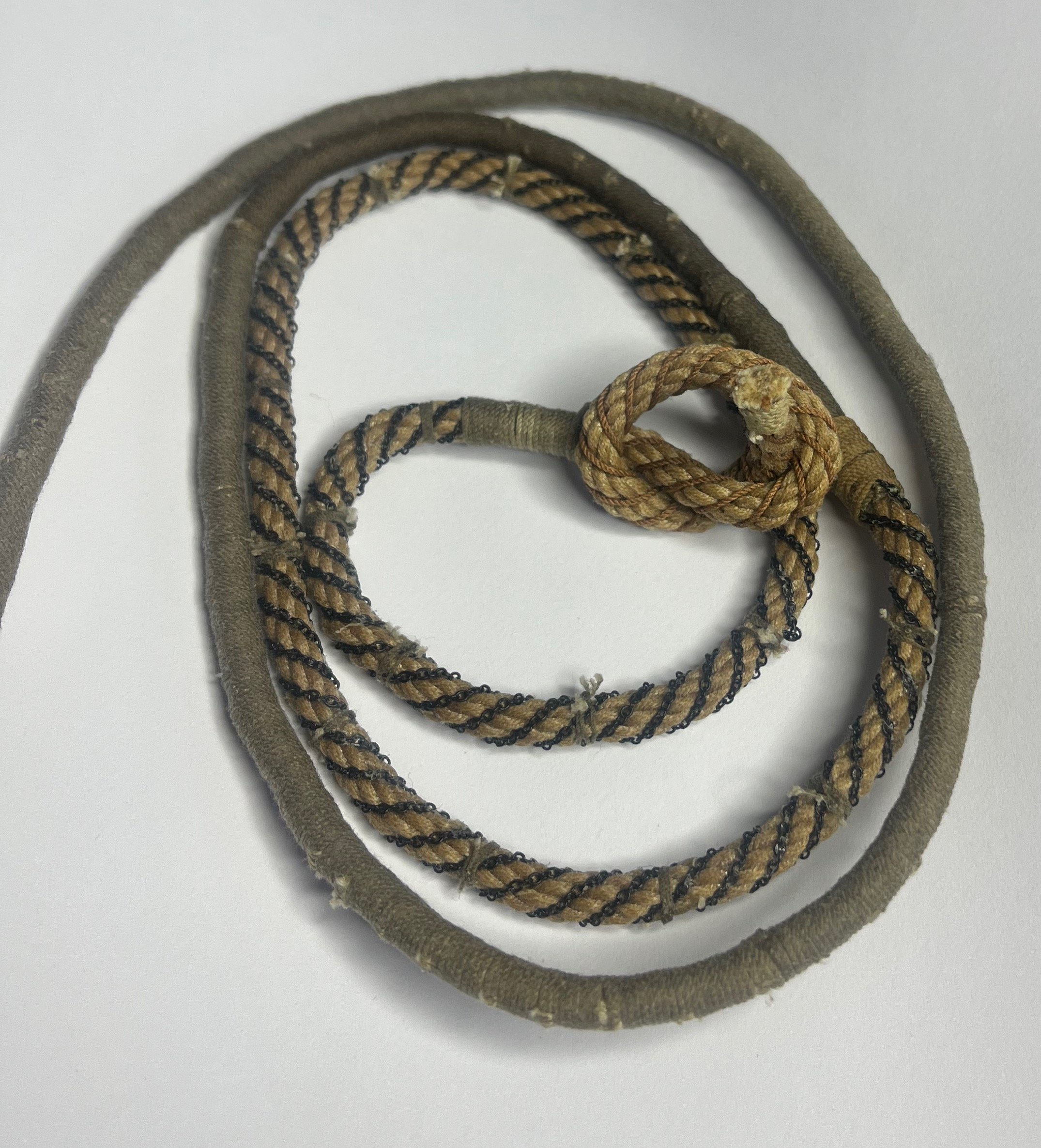
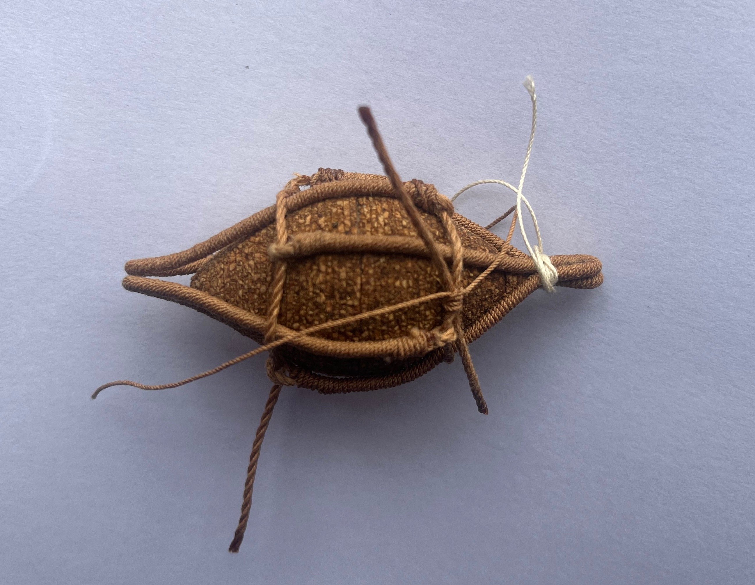
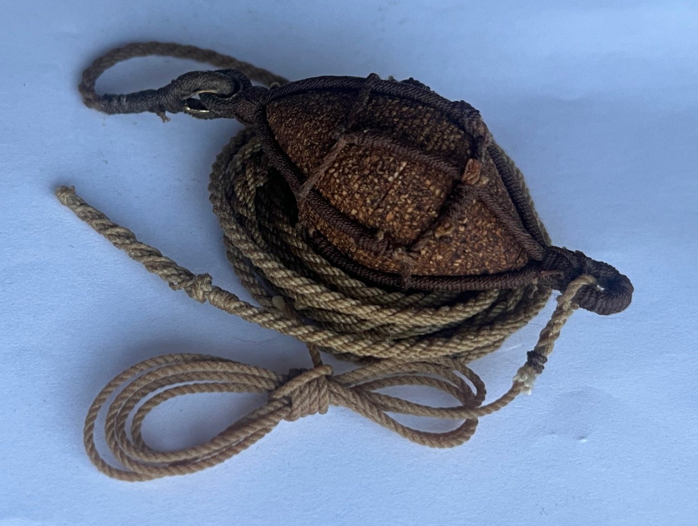
Buoy done. I used eye splices for both ends as there were too many variables to make a decision on the 'bend'. Buoy rope has two long splices now and a re-done double-wall knot. All ropes painted with 25% Stockholm tar, 75% boiled linseed oil. Next step - bit of tidy up work on the anchor and attach the buoy. I'll probably generate a new topic for the longboat that this lot is going to play a part in.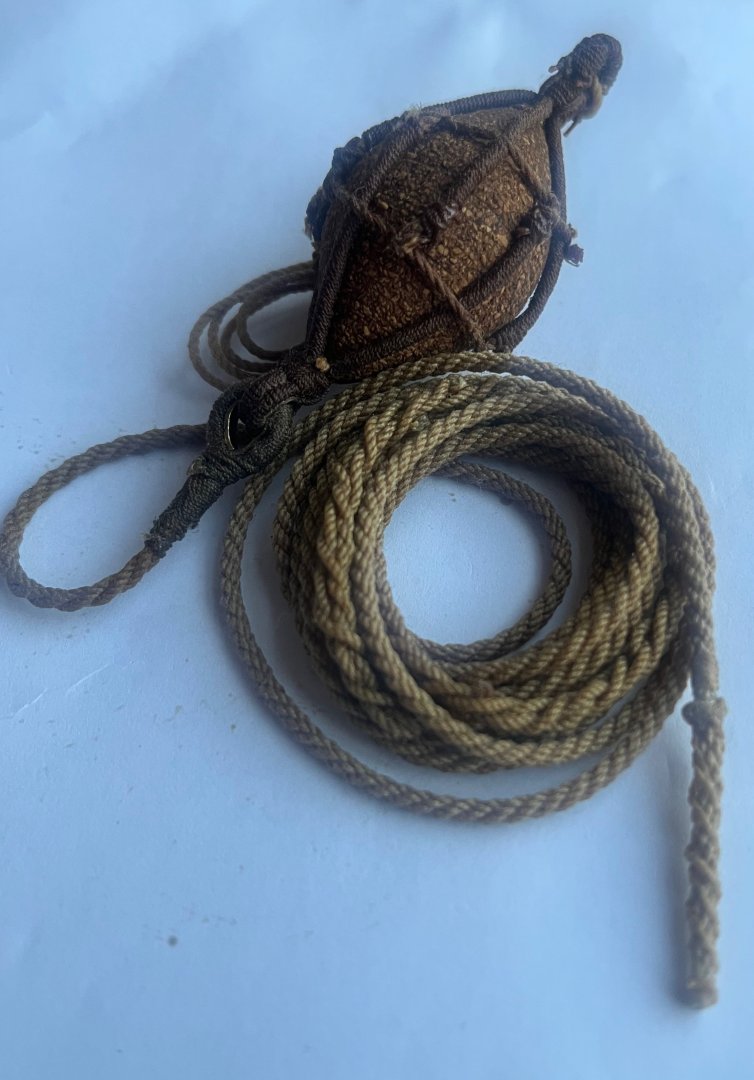
-
Bower anchor project by Sizzolo
Sizzolo replied to Sizzolo's topic in - Build logs for subjects built 1751 - 1800
Cheers Trevor. Yup, I think also I’m starting to understand that sailors were expected to apply and remove the rope-work quite frequently. I’m arriving from my modern ship-model mindset in assuming everything was fitted once, perfectly, and never aged. However, I feel it’s more likely that seizing, servings and splices were frequently removed and applied rapidly and accurately. It was likely a measure of a good sailor. (I’m having flashbacks to that scene in Jaws but you know what I mean).
-
Bower anchor project by Sizzolo
Sizzolo replied to Sizzolo's topic in - Build logs for subjects built 1751 - 1800
I made an edit to my earlier post - both lever and Steel indicate the rope was bent to the double thimble. Steel: Another thimble is turned into the thimble in the other end, for bending the buoy rope to. Lever. There is often a thimble seized in the bights, round which is another thimble, and to it the buoy rope is bent. A laniard (1) is spliced to the upper eye of the slings. But also, unhelpfully “The other end is spliced to the thimble in the bight of the buoy slings. “ So, I read that as Lever saying if another thimble (often) was around the buoy thimble the rope was bent instead of spliced. -
Bower anchor project by Sizzolo
Sizzolo replied to Sizzolo's topic in - Build logs for subjects built 1751 - 1800
Actually I’ve a feeling the sheet bend that Steel mentions is most likely the other end of the buoy in the Boudriot drawing - and that wouldn’t lend itself well to a double-thimble setup. So - to be replaced with an eye splice I think, and I’ll probably marl it. The other end of the buoy for the lanyard - I’ll probably use the splicing that you see in the cable in my last pic - with a loop to help manage the buoy when it’s pulled aboard. Anyway, a major objective of this project was to build a decent ropewalk and become more familiar with knots etc, so that when I transition to the rigging of HMS Diana in 1/64 I can feel more comfortable. There’s nothing like hitting a wall (knot) in a major project that you’ve spent years on! -
Bower anchor project by Sizzolo
Sizzolo replied to Sizzolo's topic in - Build logs for subjects built 1751 - 1800
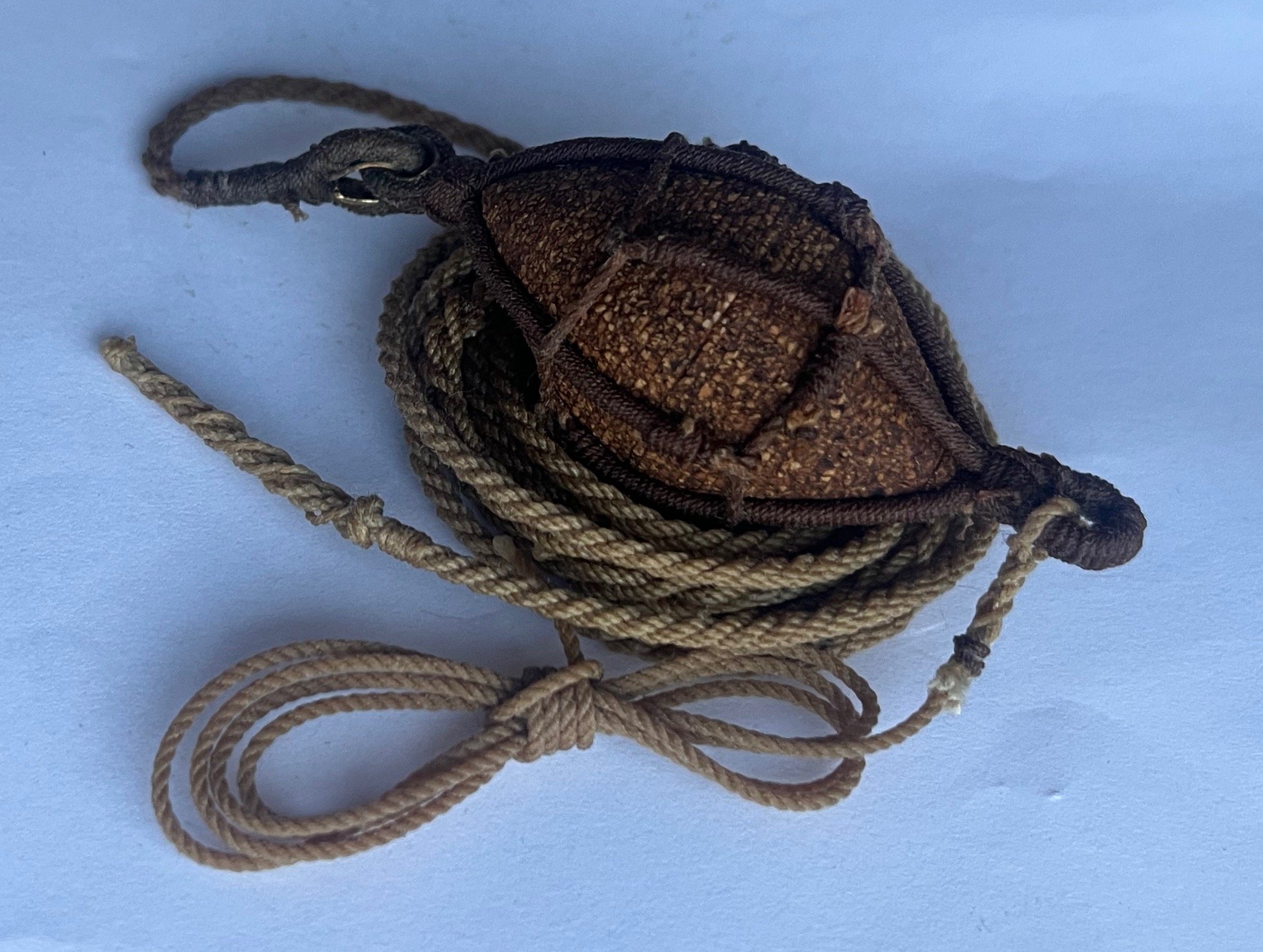
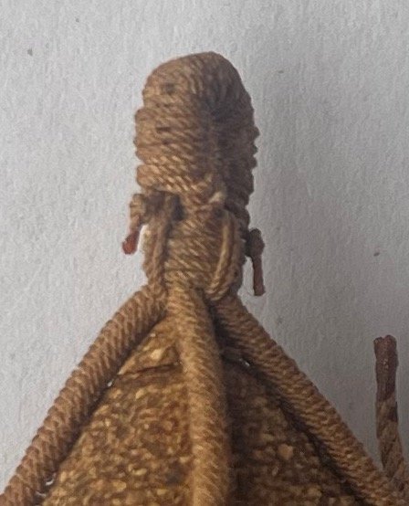
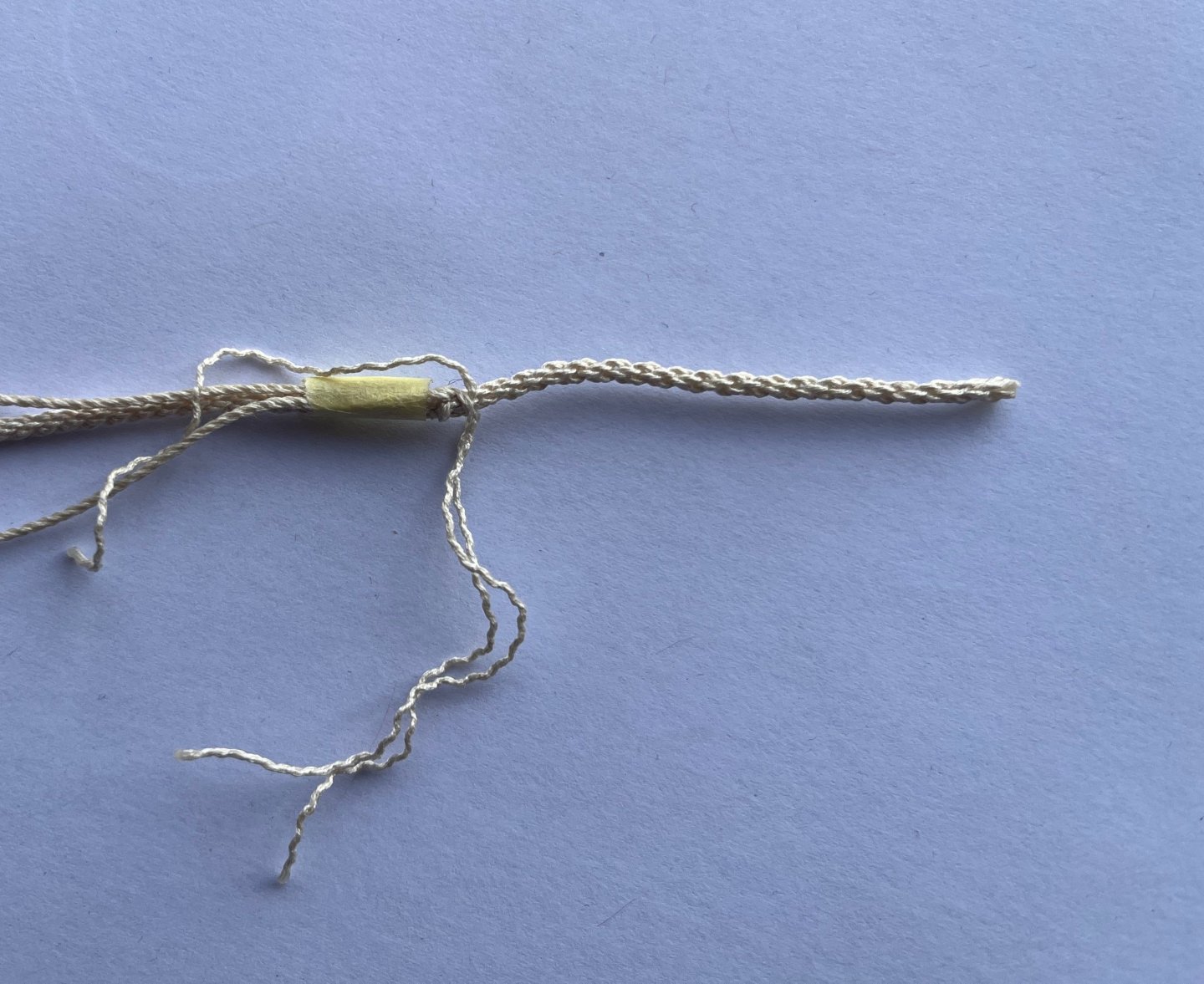
I tried the double wall again after seeing Trevor's reference (I think my first attempt was correct but, just not accurate and the threads got fuzzy so I could do better). This time I coloured the threads to make sure I didn't do the knitting wrong, and used hair gel on the cable to make it keep its shape better, and used Japanese wax on the thread to reduce the fuzziness occurring after all the tweezer work. I'm much happier with this effort (although I went anticlockwise instead of clockwise again which is why I didn't worm this test!). I think I'll make an extra length of cable and splice it to the end of the current buoy rope with a better buoy rope knot on it (longer buoy ropes were used for deeper waters, plus Steel's length is on the shorter end (102 cm) of other references which could result in another 40cm in 1/32 scale) Here's the top of the buoy with the appropriate work; Steel: "Large buoys have seven under and six riding turns smaller buoys six under; and five riding turns; the end of the seizing crossed each way, and the end knotted and crowned." ...and here's the bottom. Steel says the buoy rope was bent to the thimble whereas Lever says it was spliced.(edit - apologies - both sources say the buoy rope was bent, not spliced to the double-thimble). So logically I used Boidroit! Well - he has a nice drawing of a bend on the buoy so I went with that. Also Steel says " The rope of a buoy is passed as a sheet, and has the end stopt.". I've a feeling, given the difference in references, sailors would have had a number of options. The bend would have been more secure though in my estimation. Anyone any reference as to how long the 'lanyard' was that attached to the top? I'm thinking roughly 5 fathoms? Perhaps it had loops in it to help when using grapnels to retrieve it? I recall reading that somewhere but can't find the reference now. Also, do you think the eye splices would be marled? I might replace the eye-splice with a stop knot - tbd.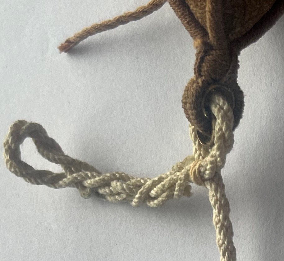
-
Bower anchor project by Sizzolo
Sizzolo replied to Sizzolo's topic in - Build logs for subjects built 1751 - 1800
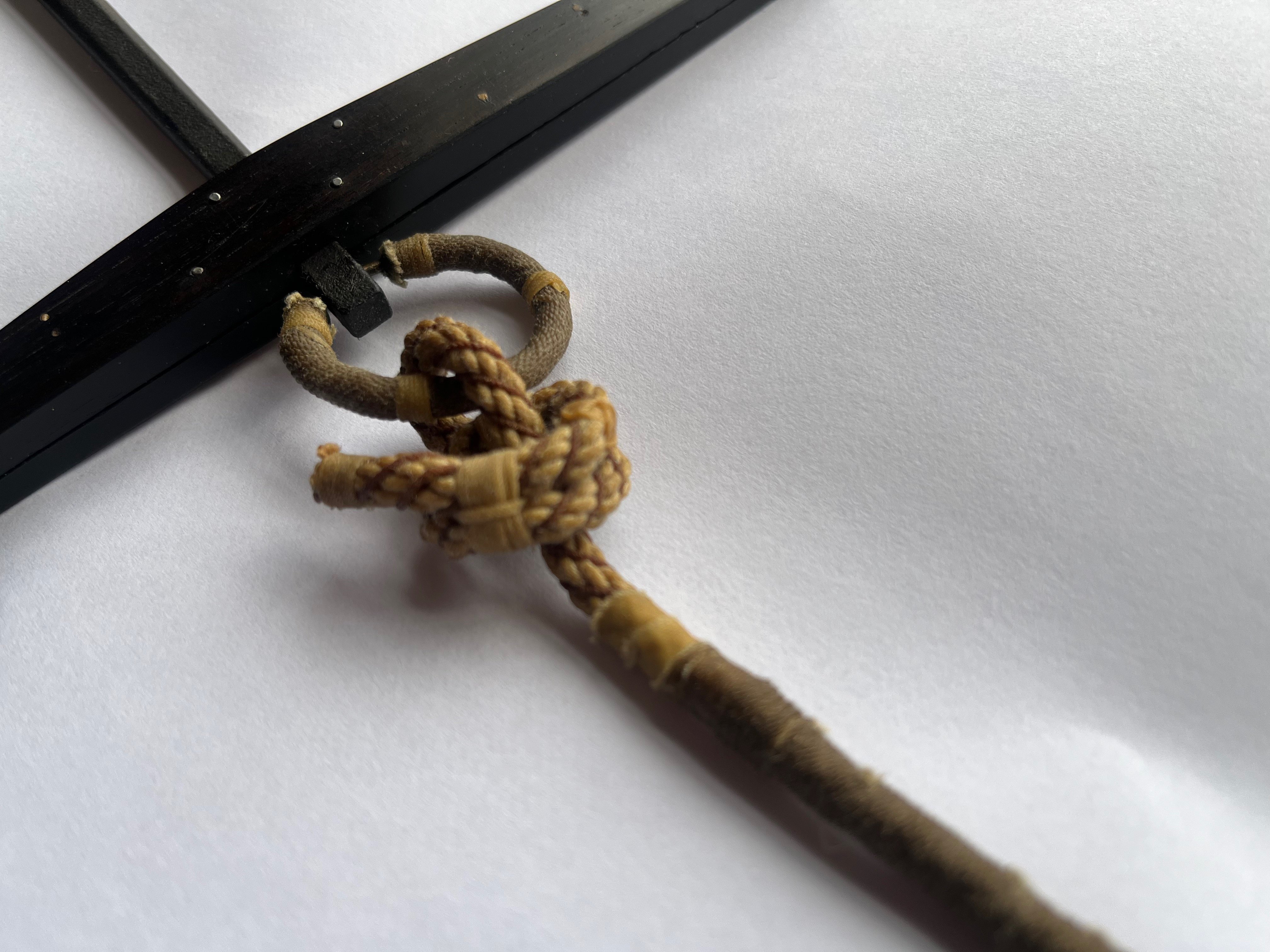
Well I was going to try it tomorrow but had a bit of a bash after work and managed to do the thimble-in-thimble! Tools used for making the saddle-curve: pretty self explanatory but, start with a steel ball slightly wider than the tube, give it a few bashes on each end (keeping ball still with some putty, and holding the tube in some needle nose pliers). Then go up a size for the steel ball, repeat, and one more larger ball. The one in the pic was the first test. After a few more tests I managed to finish it: I just need to add a little antiquing fluid. Annoyingly I have to undo the eye-splice in the buoy-rope and re-attach it through these parts.
-
Bower anchor project by Sizzolo
Sizzolo replied to Sizzolo's topic in - Build logs for subjects built 1751 - 1800
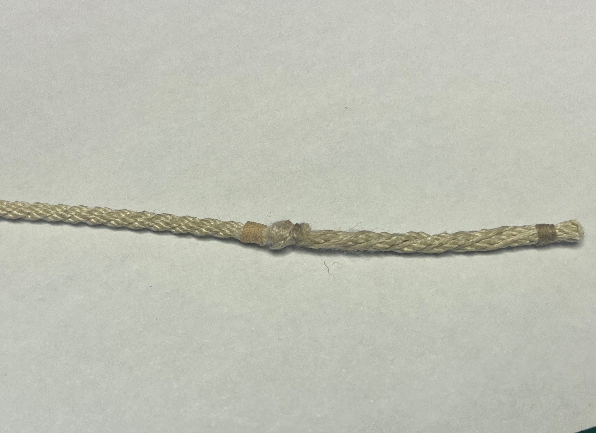
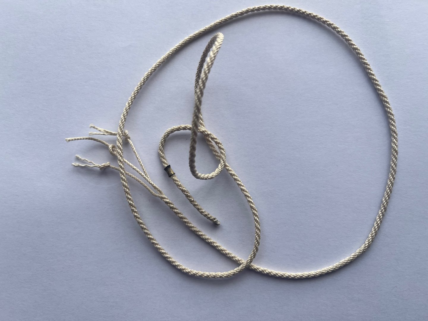
Long splice on the buoy-rope:

-
Bower anchor project by Sizzolo
Sizzolo replied to Sizzolo's topic in - Build logs for subjects built 1751 - 1800
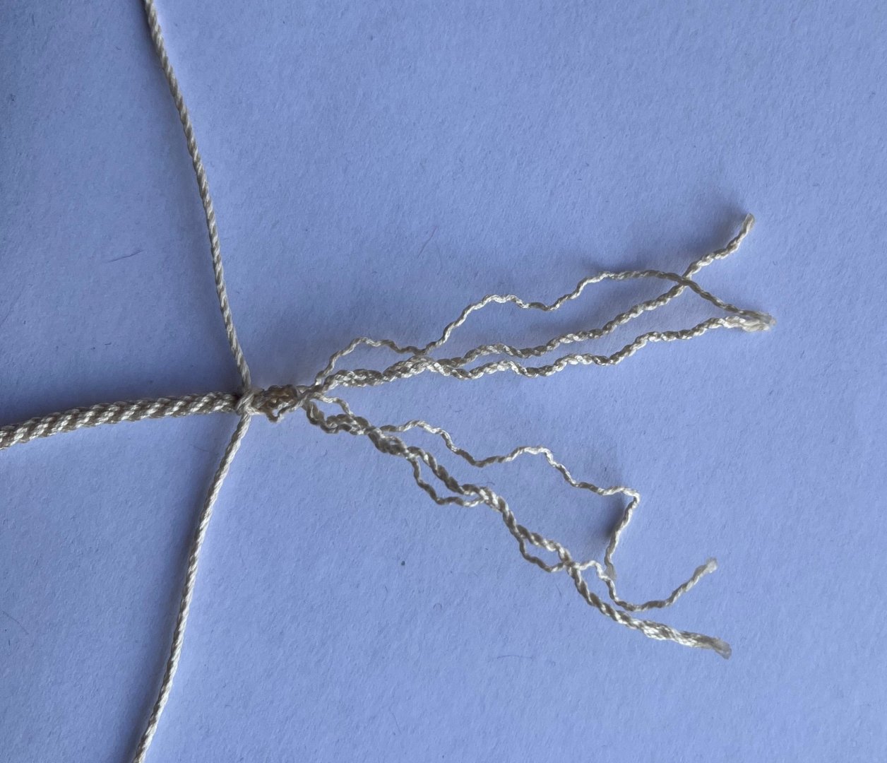
I first read that to mean 'wall and go round twice' but it ended up just being a plait with nothing holding it to the main rope. I then tried weaving one under two and that didn't work. Eventually I read it to mean wall normally then another wall weaved under the first. The ends are then wormed up the original rope. If I were to do it again I'd use hair-gel on it first to help the strands keep their form. (a tip I found when watching this great channel: ) -
Bower anchor project by Sizzolo
Sizzolo replied to Sizzolo's topic in - Build logs for subjects built 1751 - 1800
Eye-splice to the 2.2mm buoy-rope.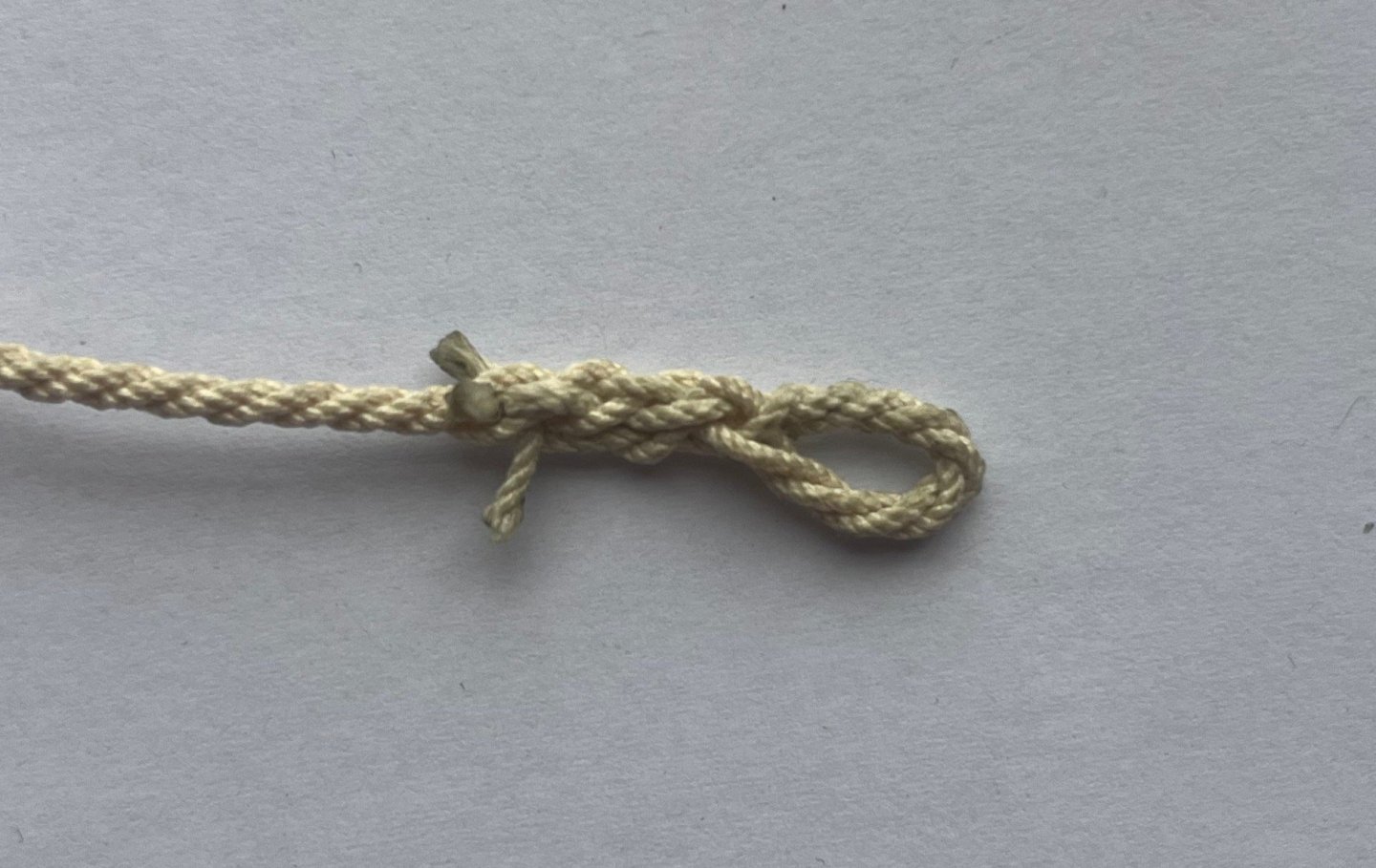
-
Bower anchor project by Sizzolo
Sizzolo replied to Sizzolo's topic in - Build logs for subjects built 1751 - 1800
I’m still investigating other more obscure methods of putting a thimble in a thimble. From what I can see in my research so far is there are two principle methods. There’s the Stoner method; or the Wizard method;

-
Bower anchor project by Sizzolo
Sizzolo replied to Sizzolo's topic in - Build logs for subjects built 1751 - 1800
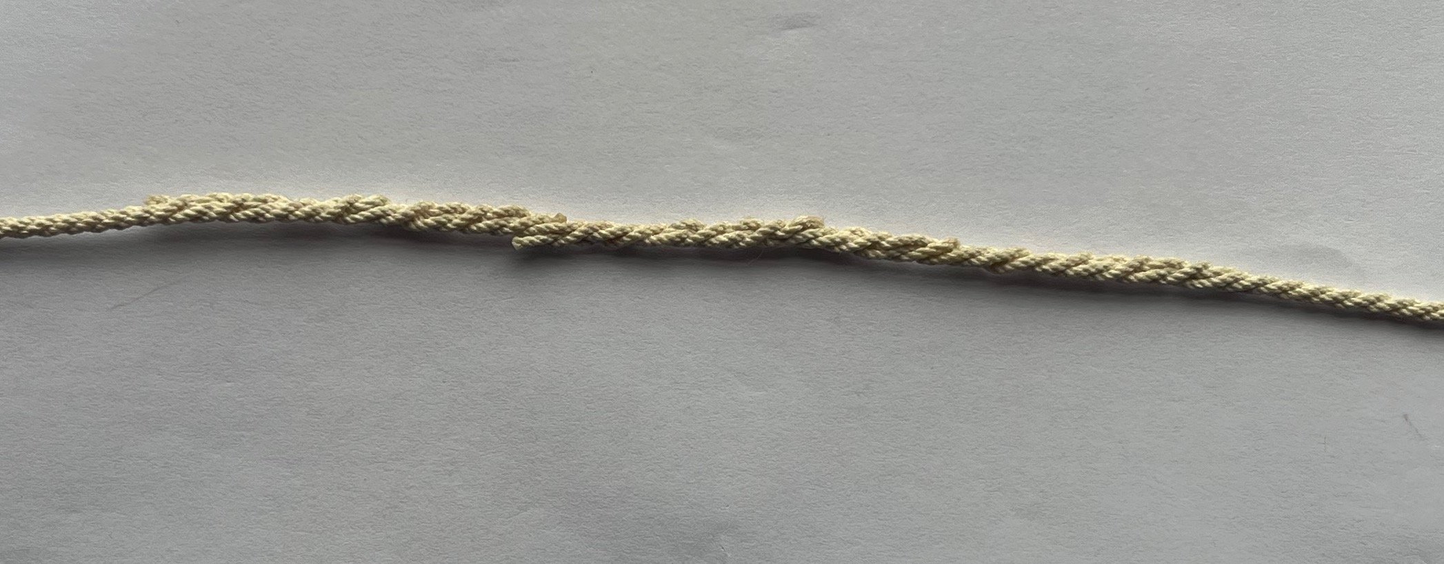
Cheers! First few efforts were v frustrating until I realised I was turning it in the wrong direction for cable. Then it just became difficult until it started working. Unfortunately the part that was re-laid lost some of its perk as you can see the angle of the contlines is more relaxed. I can live with that though as when I bind it to the anchor I can tighten it up a bit. Hardware for the thimble-in-thimble arrived today (steel balls of various diameters, a selection of brass tubes). Hope to get that sorted on the weekend. I guess the interesting discovery here is that the buoy-rope thimble must have been split, similar to the modern tear-drop thimble that Trevor mentioned. Possibly identical to them as the drawing from Lever’s book above does look a lot like a tear-drop inside a standard circular thimble. The drawing also suggests the bights at both ends were not served together, nor does the text say so. -
Bower anchor project by Sizzolo
Sizzolo replied to Sizzolo's topic in - Build logs for subjects built 1751 - 1800
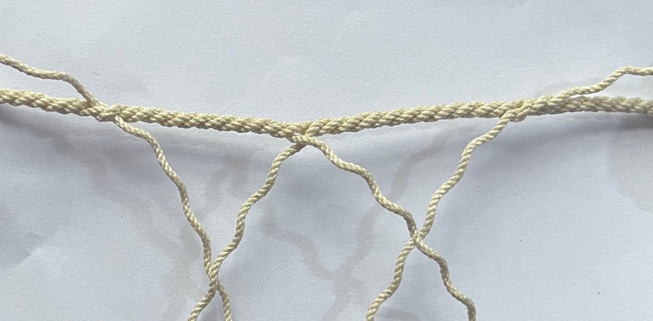
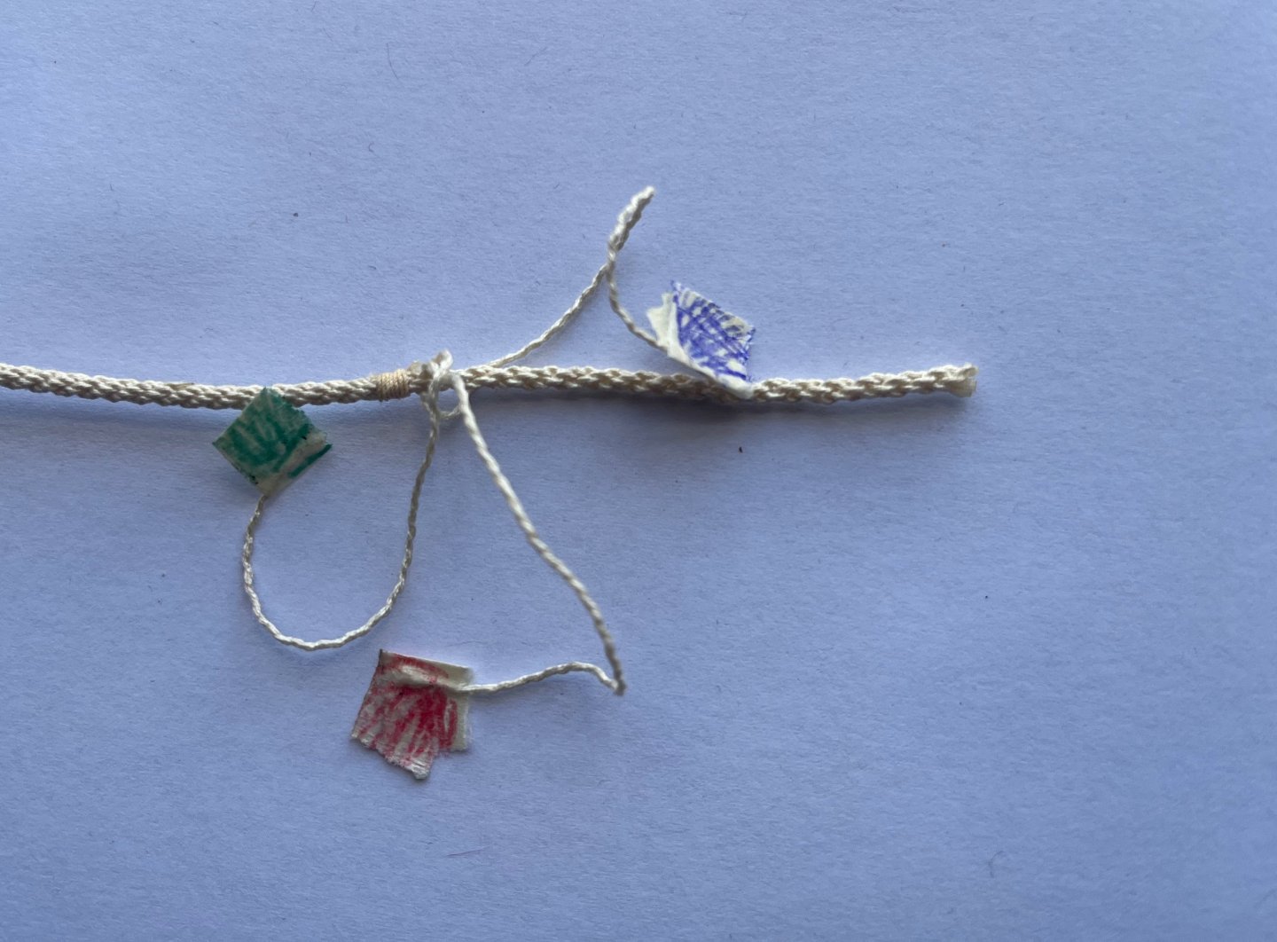
My lunch break was a bit longer today! Buoy rope knot (according to Lever) "One end is unstranded for one yard in length, stopped with rope-yarn, and one of the nine smaller strands taken out of each of the three larger strands,.." "...which are then laid together again." "The three smaller strands are double-walled right-handed close to the stop, then laid up their contlines,.." The hardest bit was building the wall. I tried about 6 times until generating the right method. The coloured flags helped keep track of which rope to weave and when etc. Next is to do a long splice to I can make the rope 103cm long... (referencing Lever again for the length.)
-
Bower anchor project by Sizzolo
Sizzolo replied to Sizzolo's topic in - Build logs for subjects built 1751 - 1800
I think you're right again Trevor: Also - Lever to the rescue!: Page 69 from The Young Sea Officer's Sheet Anchor: "the bights at each end are then seized with a round seizing (see page 9), and double crossed. There is often a thimble (m) seized in the bights, round which is another thimble, and to it the buoy rope is bent. A laniard (1) is spliced to the upper eye of the slings." It seems to align very well with what Steel is describing, and your assessment. So - two good sources and some wisdom... helps a lot! Now I've got to figure out how to make a thimble in a thimble with the brass tube I have. . . .fiddly!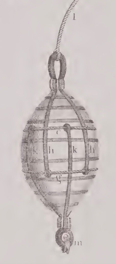
-
Bower anchor project by Sizzolo
Sizzolo replied to Sizzolo's topic in - Build logs for subjects built 1751 - 1800
More progress pics! I accelerated a bit so didn't make time to take pics as things developed - lots of work on the buoy. I spent a while making rope until the diameter of the buoy-rope (cable) was correct (2.2mm). I tried using my charts to estimate the number of threads and type of thread would result in a 2.2mm cable but kept just missing it. All sorted now though although to make the full 40m (1.25m in 1/32) I'll need to splice two together (the model will need to show the full length as it travels from the anchor to a coil in the ships longboat). I practiced a bit of splicing and - what a pain! I'm also going to try the fiddly buoy-rope-knot as described in Steel. You might spot a thimble test at one end of the buoy rope - that's 2.5mm OD brass tube after a bit of shaping. For the hoops - Steel says "In the merchant service they are wormed and served; but not in the king’s service." so that saved me a bit of time! Any ideas what Steel means by "Another thimble is turned into the thimble in the other end, for bending the buoy rope to"? As it stands, I could just model it based upon his previous statement "with a thimble in one end, and an eye at the other". I guess he might mean that as a previous step one thimble was added and the final step is to add another thimble at the other end too? Likely... Seizing completed on the anchor end of the bower cable. The keckling is taking forever as 5cm of serving needs 1.3m of rope (which in turn needs three strands of 4 threads .. . so 1,560cm of thread to make 5cm of serving...). Then there's the fiddly seizing every 8 turns. Good idea to have radio/tv playing at the same time!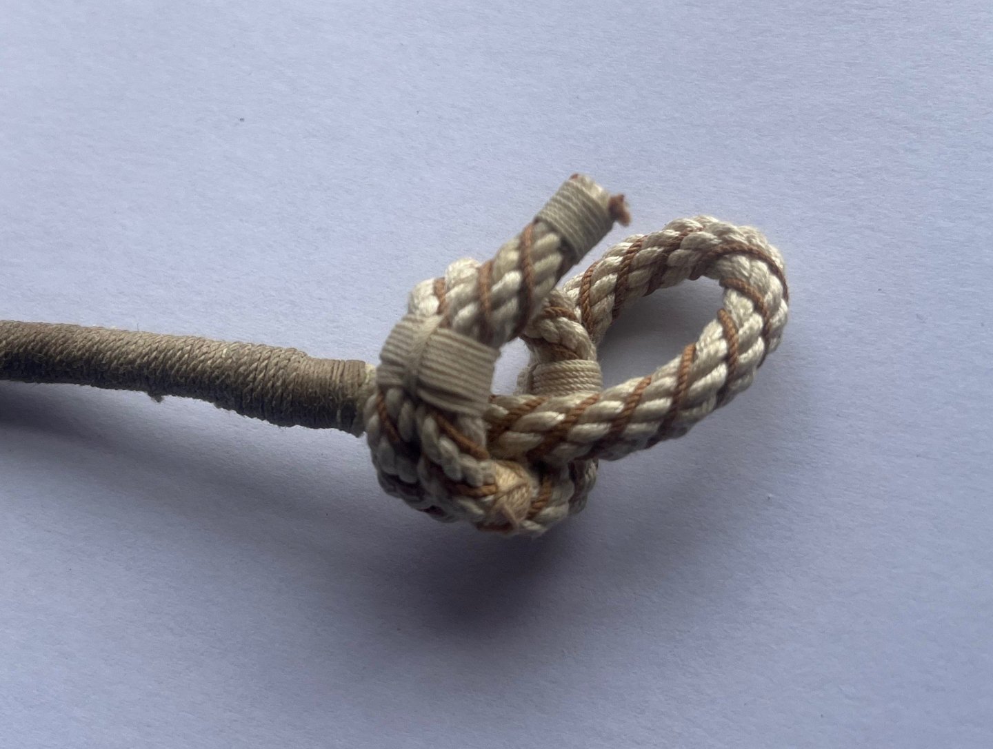


-
Bower anchor project by Sizzolo
Sizzolo replied to Sizzolo's topic in - Build logs for subjects built 1751 - 1800
Thanks Trevor. Yes I think your assessment is sensible. It probably demonstrates just how busy sailers were during their shift. After a few years of practice they probably got quite fast at it when the cable was regularly re-served and repaired. I'm glad I did two methods first as, yes, the third is subtle enough to add an element of interest to the model without making it look like a twiglet.
-
Bower anchor project by Sizzolo
Sizzolo replied to Sizzolo's topic in - Build logs for subjects built 1751 - 1800
I think this is better: This probably makes more sense and wouldn't promote chafing or damage to the hawseholes.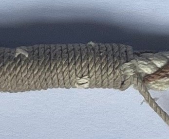
-
Bower anchor project by Sizzolo
Sizzolo replied to Sizzolo's topic in - Build logs for subjects built 1751 - 1800
Unfortunately not. That's all he said as far as I can see: https://maritime.org/doc/steel/part10.php Completely agreed with your points. I suspect the 'stopping' was either similar to my first method which was just a half hitch in the service itself, or, more likely was sewn into the service with a palm, using finer thread which bound two turns together but not protruding as much as the ones in my model which are just wrapped around two turns. Or (another thought) was a line that used fitted down the contlines of the turns and lashed - again being more concealed. I'll probably stick with my method 2 as it's taking long enough as it is It's lunchtime now though so I guess one more method.... -
Bower anchor project by Sizzolo
Sizzolo replied to Sizzolo's topic in - Build logs for subjects built 1751 - 1800
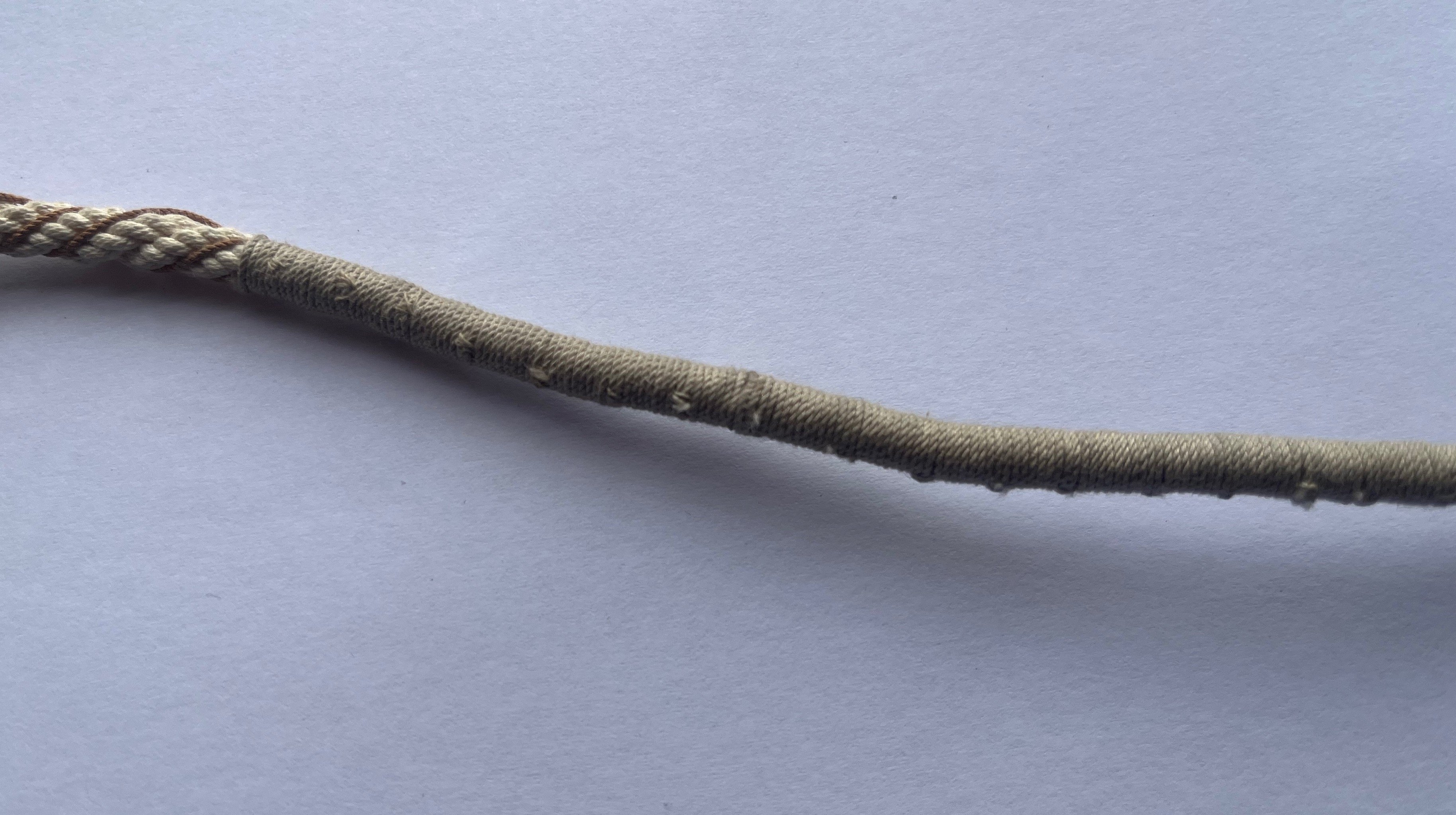
I think this is more appropriate: for spun yarn I used 2-thread, 2-strand rope with 0.35mm diameter. Spot of superglue on the reef knot to keep it secure. Again, the eventual Stockholm tar will neaten things up. It's going to take a while to do the roughly full 4 fathoms (60cm to scale) but should be worth it in the end.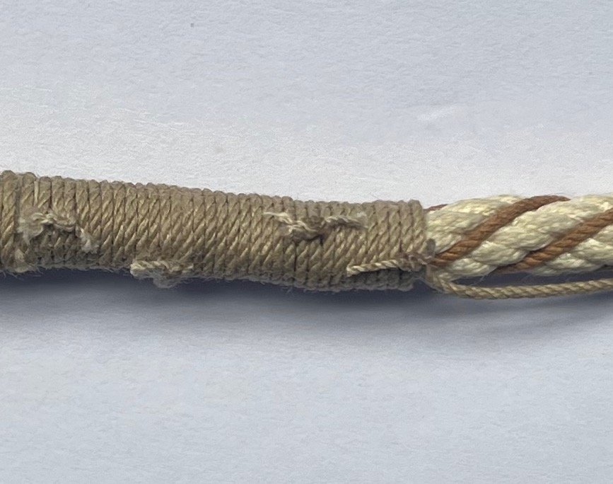
-
Bower anchor project by Sizzolo
Sizzolo replied to Sizzolo's topic in - Build logs for subjects built 1751 - 1800
Steel: The Elements and practice of Rigging and Seamanship" 1794: "TO PREVENT CABLES FROM CHAFING by friction...care taken to stop the service with spun-yarn at every six or eight turns." This is a pic of stopping the service but, not using separate spun yarn so just a test. I'll try a section with separate 'stop's.