gak1965
-
Posts
727 -
Joined
-
Last visited
3 Followers


Recent Profile Visitors
2,848 profile views


-
 Canute reacted to a post in a topic:
RRS Discovery 1901 by gak1965 - 1:72 - First Scratch Build
Canute reacted to a post in a topic:
RRS Discovery 1901 by gak1965 - 1:72 - First Scratch Build
-
 Keith Black reacted to a post in a topic:
RRS Discovery 1901 by gak1965 - 1:72 - First Scratch Build
Keith Black reacted to a post in a topic:
RRS Discovery 1901 by gak1965 - 1:72 - First Scratch Build
-
 Thank you! I have a small lathe so that should be doable, albeit with a lot of practice. As a general note, I've looked through your Tennessee build, which is amazing. I have learned that when I hear someone here say my "humble", "okay", "acceptable", etc. around here that I should expect to be astonished!
 -
gak1965 reacted to a post in a topic:
RRS Discovery 1901 by gak1965 - 1:72 - First Scratch Build
-
JacquesCousteau reacted to a post in a topic:
RRS Discovery 1901 by gak1965 - 1:72 - First Scratch Build
-
ccoyle reacted to a post in a topic:
RRS Discovery 1901 by gak1965 - 1:72 - First Scratch Build
-
Jared reacted to a post in a topic:
RRS Discovery 1901 by gak1965 - 1:72 - First Scratch Build
-
Canute reacted to a post in a topic:
RRS Discovery 1901 by gak1965 - 1:72 - First Scratch Build
-
Paul Le Wol reacted to a post in a topic:
RRS Discovery 1901 by gak1965 - 1:72 - First Scratch Build
-
Keith Black reacted to a post in a topic:
RRS Discovery 1901 by gak1965 - 1:72 - First Scratch Build
-
Dr PR reacted to a post in a topic:
RRS Discovery 1901 by gak1965 - 1:72 - First Scratch Build
-
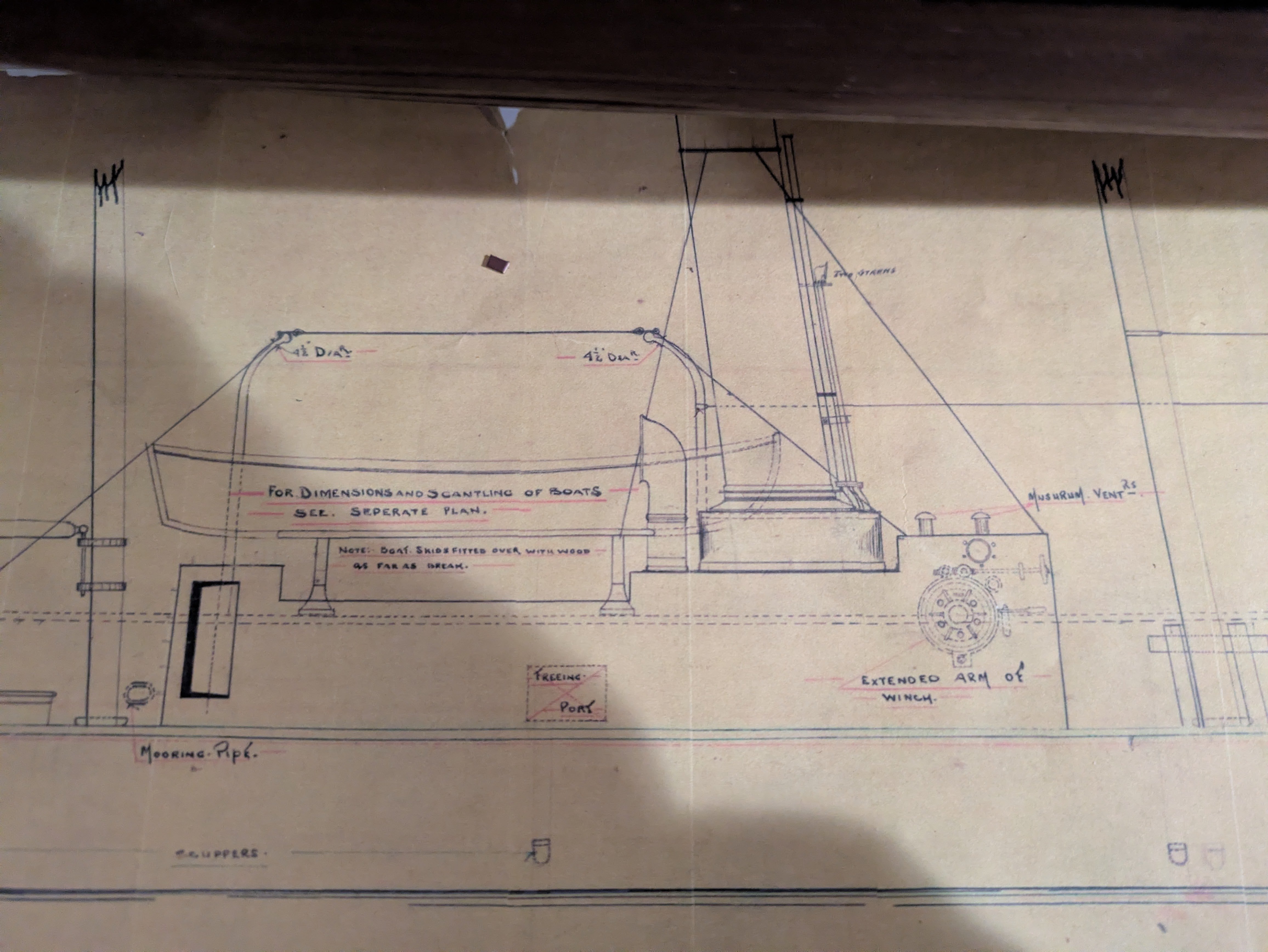
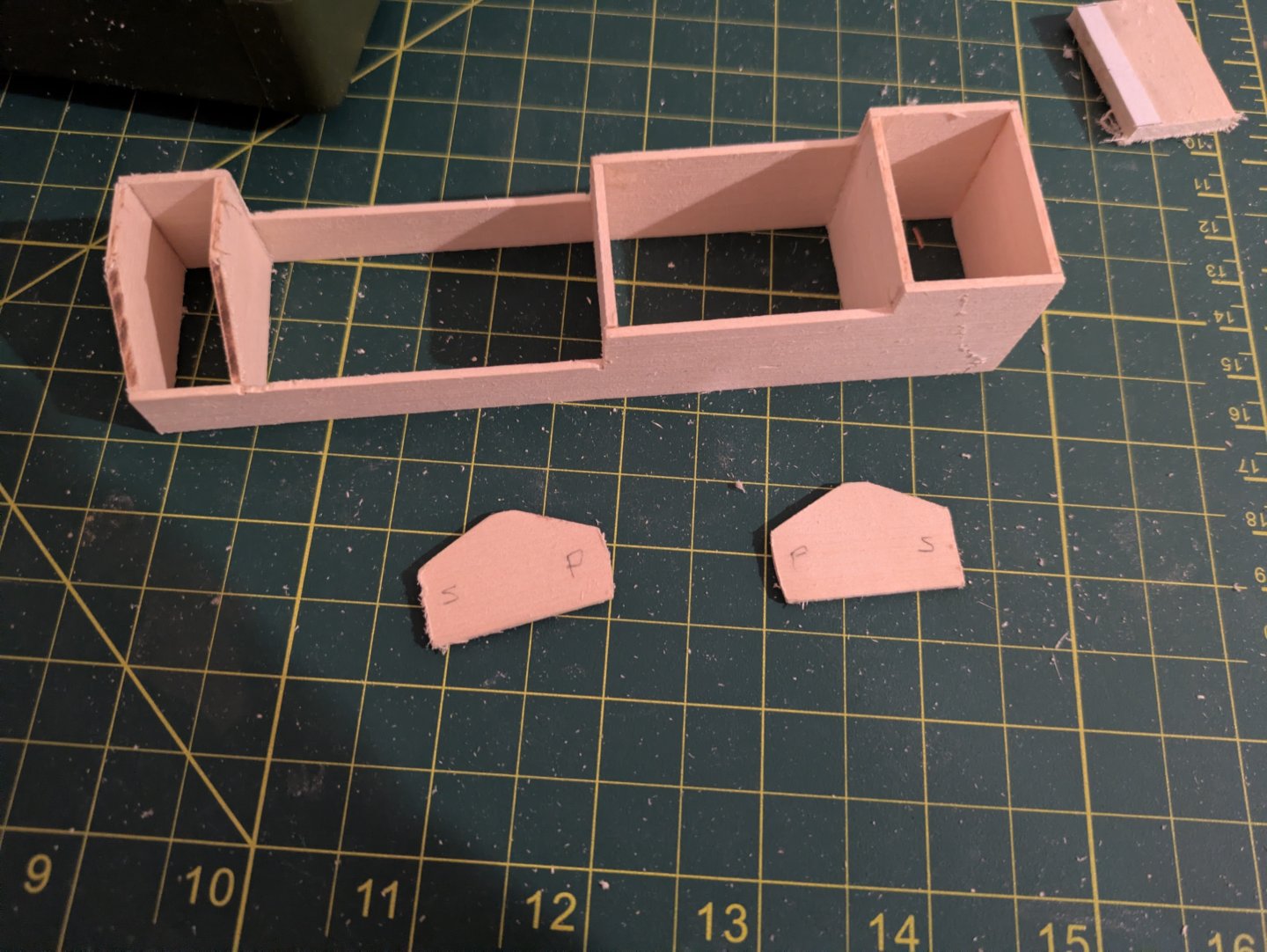
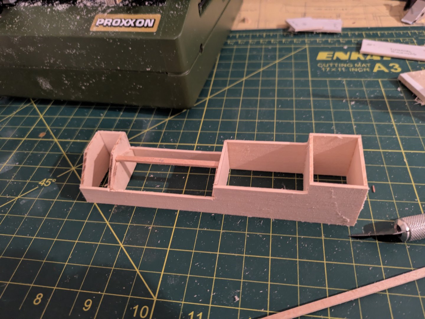
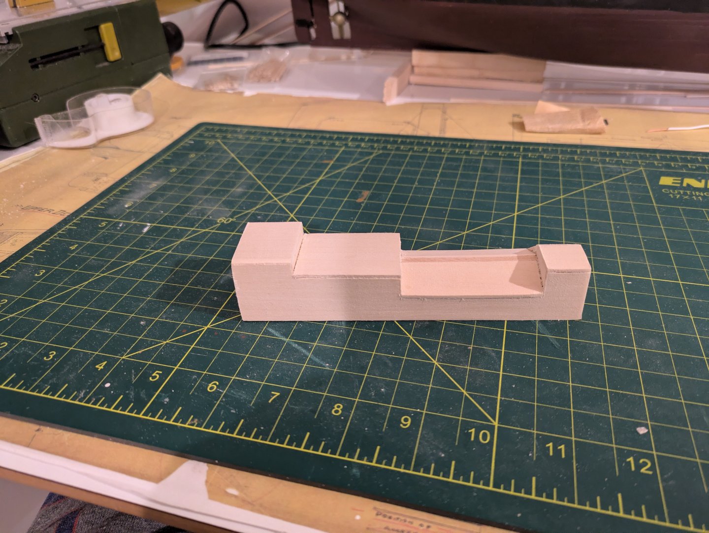
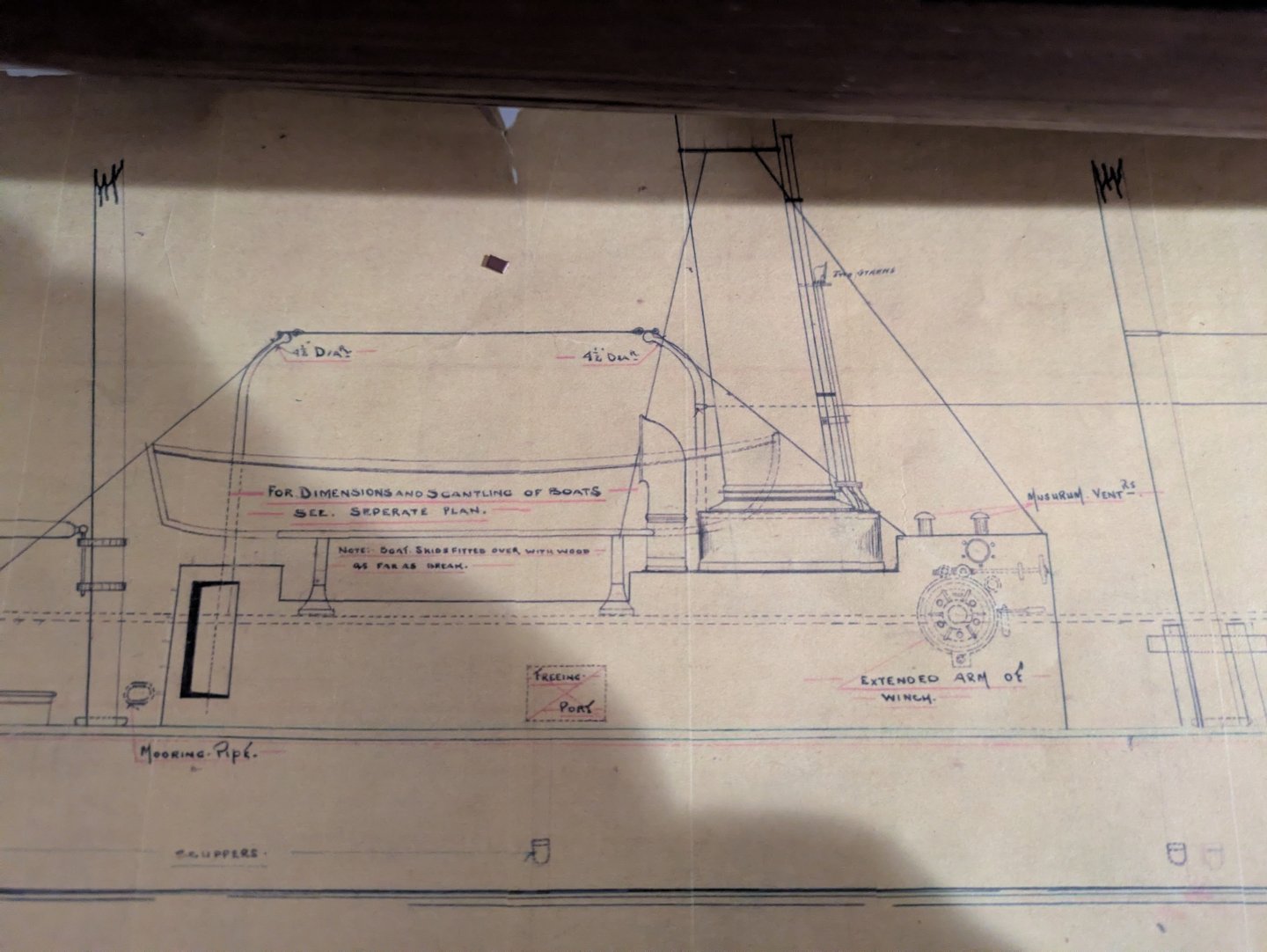
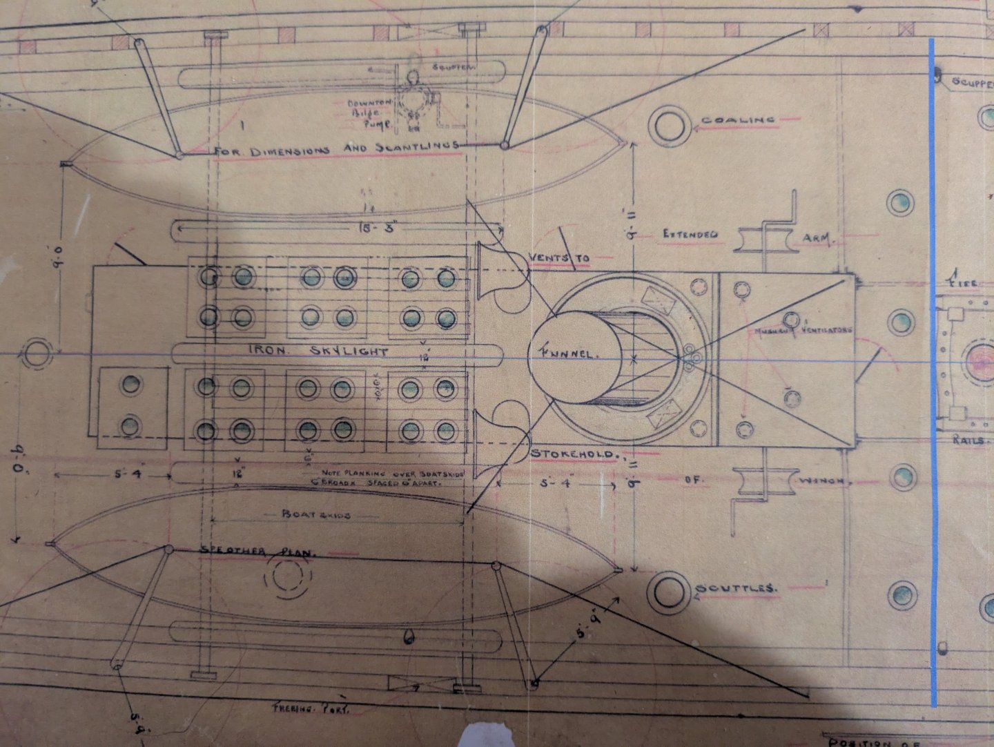
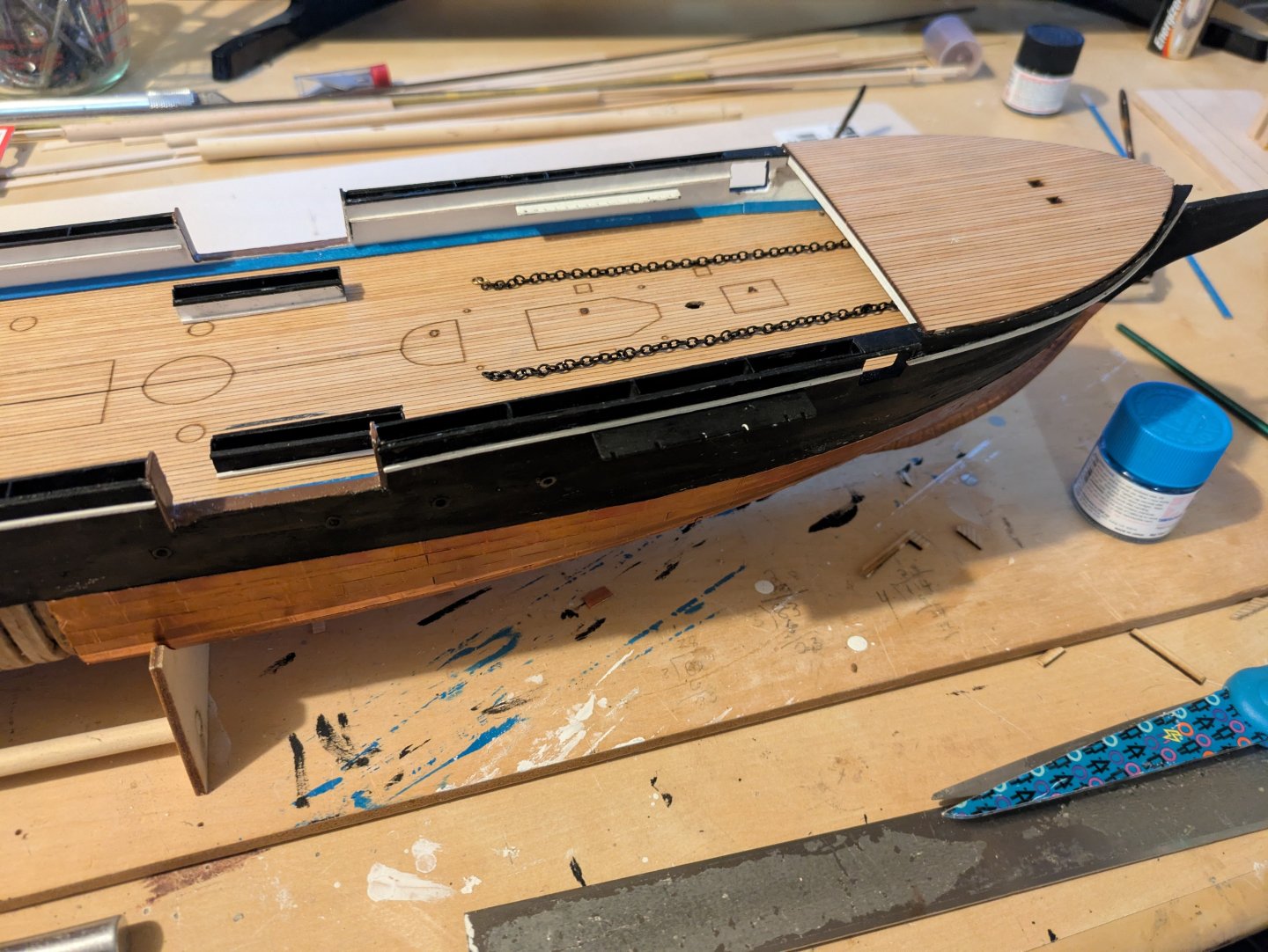
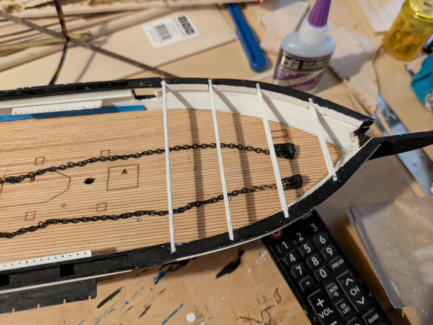
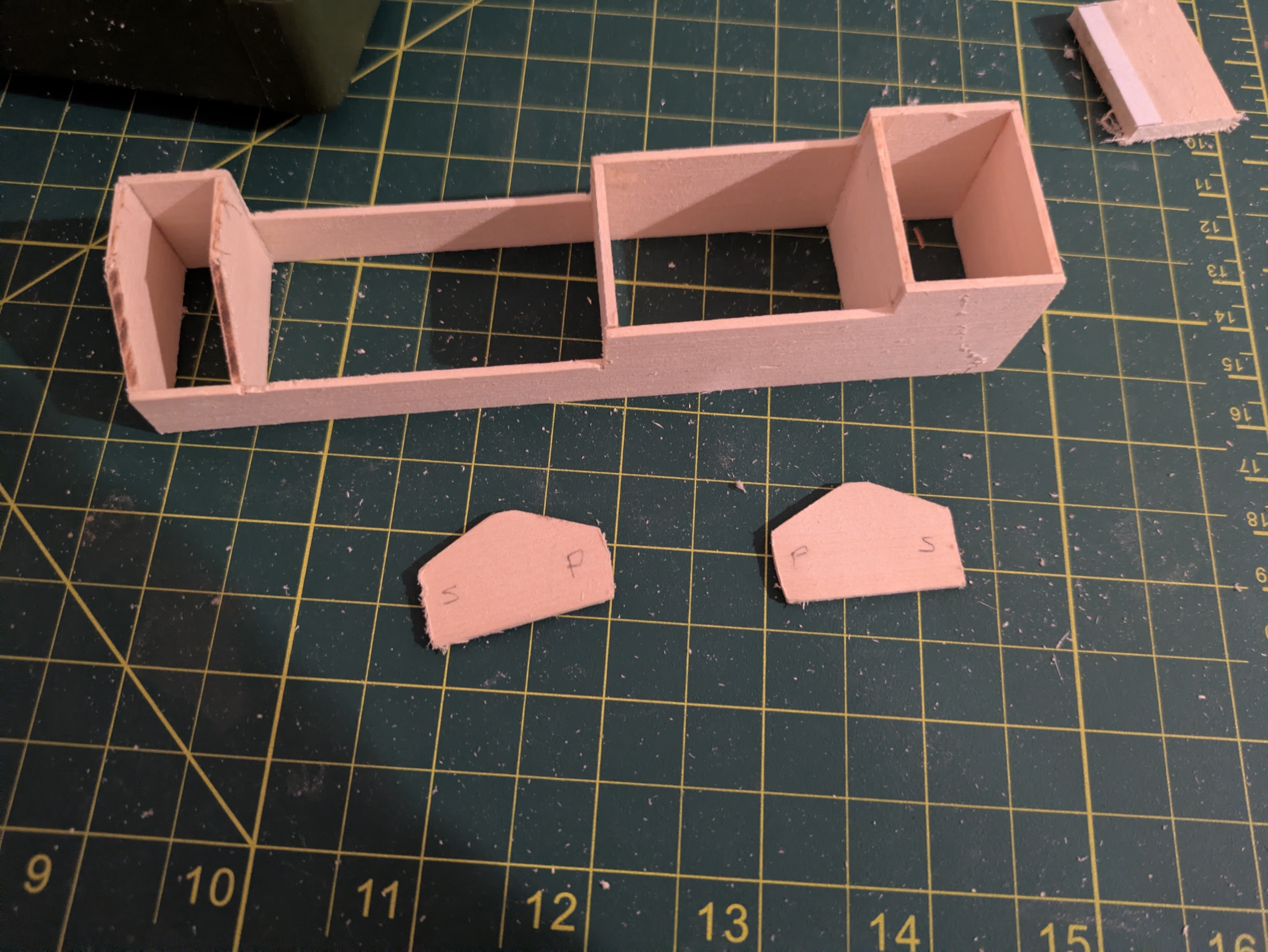
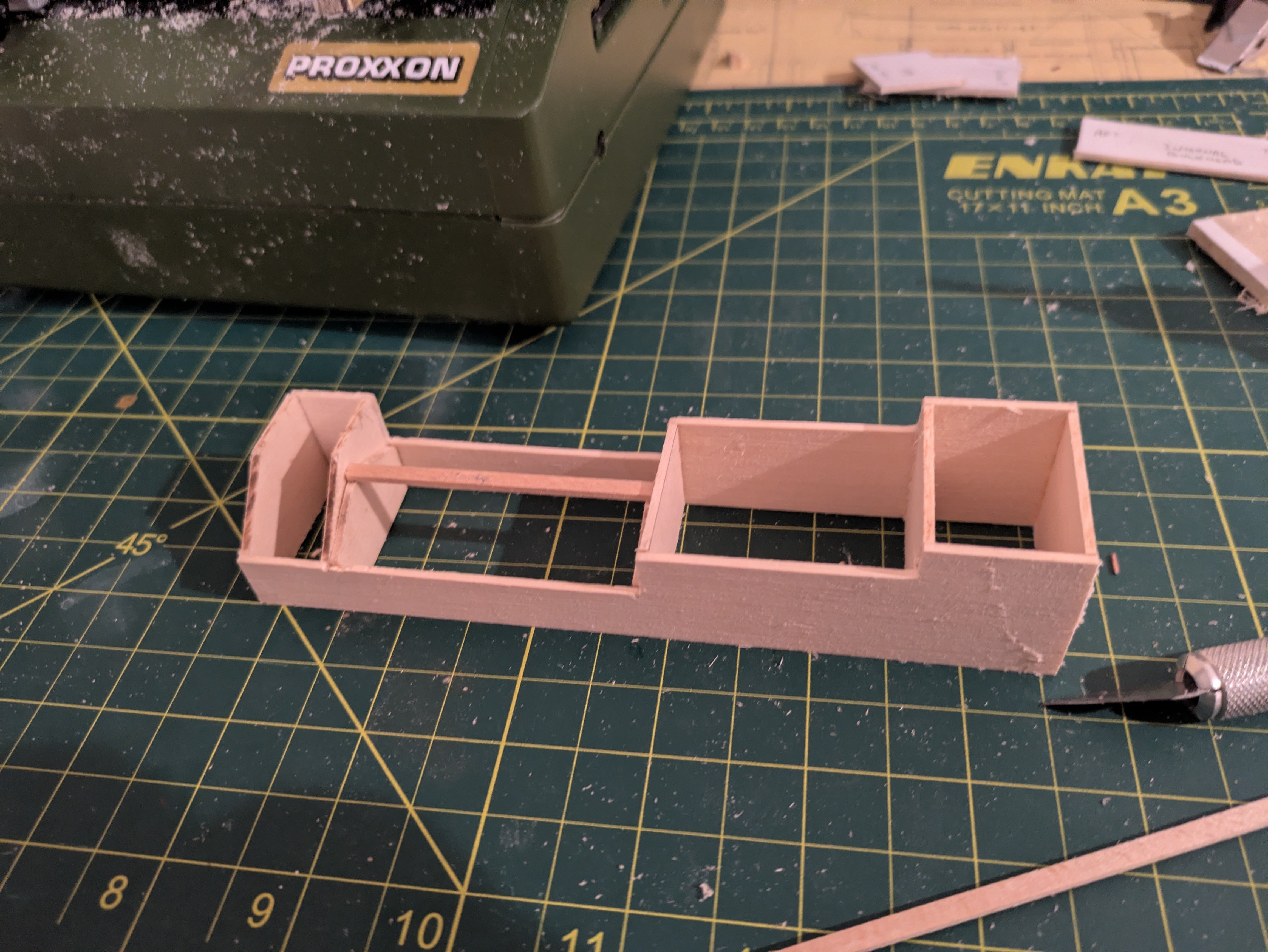
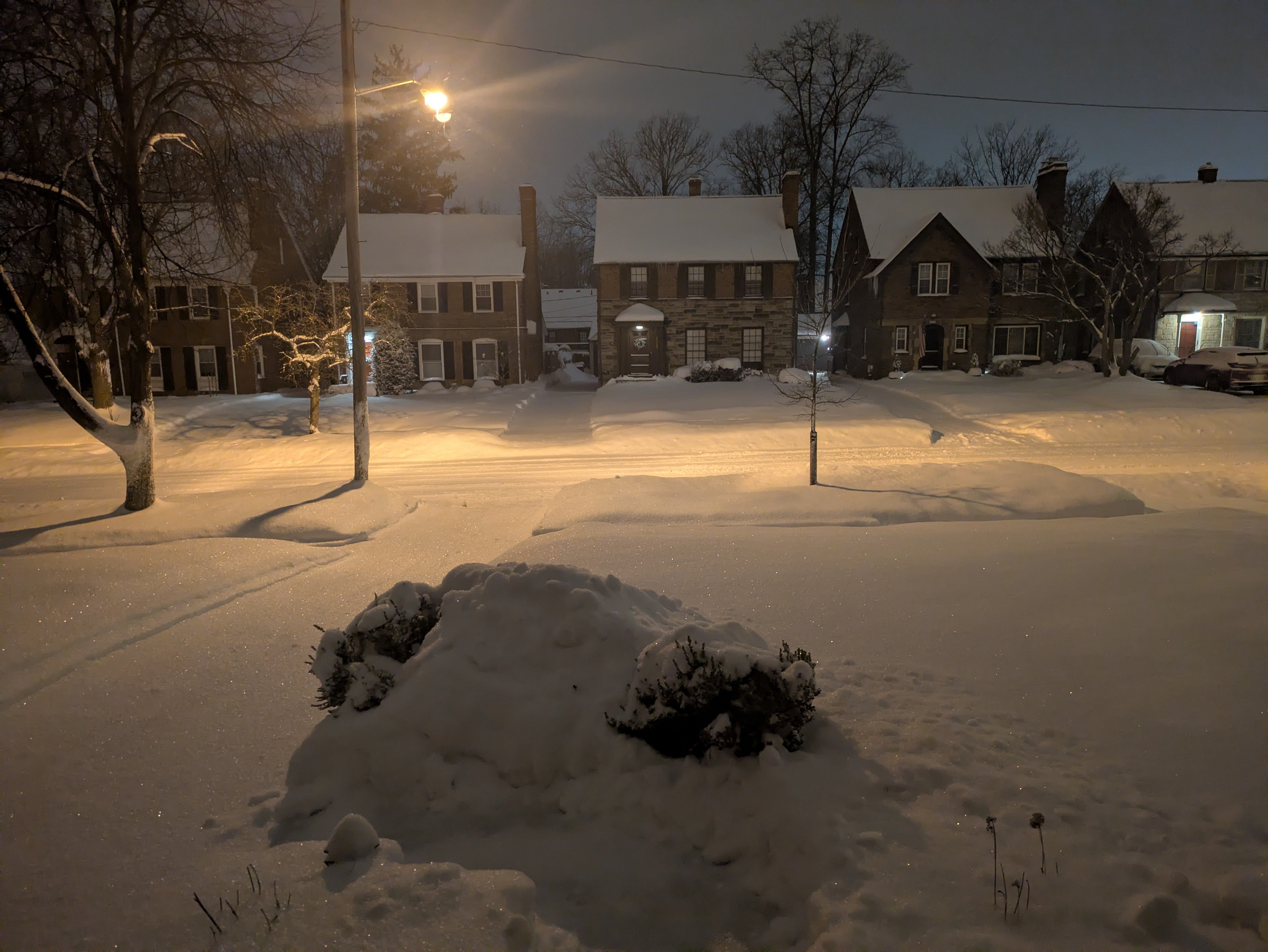
Back and forth to DC once since my last update, so some work on the Kearsarge but mostly in Cleveland so more to show on the Discovery. But first, it's been an interesting re-introduction to Lake Effect snow and temperatures north of the Mason Dixon Line: Supposedly this has been the coldest, snowiest winter in Cleveland since the '50's (first snow was Nov 10, and we've only had a handful of days where I could see the grass since). I have spent years ignoring my wife's entreaties to save my back and buy a snow blower, but I finally caved on Friday, primarily because there is no where to shovel the snow between the houses where our driveway is, and so I've been forced to pick up a shovelful, walk to the front yard, dump. Rinse and repeat. It takes a 20-40 minute job (if there had been someplace to toss it) and makes it 60-90. Oh well. Back to the ship. I was working on the cover for the engine room. Just a couple of quick pics to remind you of what it looks like. Here are the plans: And here is a picture of the modern ship that had the front section removed: I cut out the pieces that were shown in the previous entry. Here is a brief overview of the construction process so far. And the basic structure completed. From the port side left is forward): Starboard side (right is forward): And looking from the starboard quarter: This still requires a ton of work. I have to make the 7 iron skylights (6 with 4 ports and 1 with 2 ports), the forward bulkhead has some kind of ports in it as well. It needs a bit of putty, and then sand and carefully prime before painting, b/c the real structure is made of iron and I don't want any wood grain showing through. I need to frame two hatches (one port side aft, the other port side in the second section from the front, build and put on the winches, make 4 mushroom vents, and the stack, and two cowl vents, etc., etc. But I think that the bones of the structure turned out okay. Speaking of which, I've been wondering how the heck to fabricate the cowl ventilators. The only example I can recall seeing is from @Valeriy V using electroplating, but I have neither the equipment nor the skill. I've searched MSW, but haven't found anything obvious. Any thoughts? I mean, I could buy them premade, but I'm trying to fabricate as much as I can, and if anyone knows a good method, I'd love to hear it. Thanks for looking in! Regards, George

.thumb.jpg.0825d1f503bc314934dfa71f4d3d42d6.jpg)


-
gak1965 reacted to a post in a topic:
RRS Discovery 1901 by gak1965 - 1:72 - First Scratch Build
-
gak1965 reacted to a post in a topic:
RRS Discovery 1901 by gak1965 - 1:72 - First Scratch Build
-
gak1965 reacted to a post in a topic:
ELBE 1 1948 by Mirabell61 - scale 1:87 - Lightship
-
gak1965 reacted to a post in a topic:
ELBE 1 1948 by Mirabell61 - scale 1:87 - Lightship
-
gak1965 reacted to a post in a topic:
ELBE 1 1948 by Mirabell61 - scale 1:87 - Lightship
-
gak1965 reacted to a post in a topic:
USS Cape (MSI-2) by Dr PR - 1:48 - Inshore Minesweeper
-
gak1965 reacted to a post in a topic:
USS Cape (MSI-2) by Dr PR - 1:48 - Inshore Minesweeper
-
druxey reacted to a post in a topic:
RRS Discovery 1901 by gak1965 - 1:72 - First Scratch Build
-
gak1965 reacted to a post in a topic:
Billy 1938 by Keith Black - FINISHED - 1:120 Scale - Homemade Sternwheeler
-
gak1965 reacted to a post in a topic:
Billy 1938 by Keith Black - FINISHED - 1:120 Scale - Homemade Sternwheeler
-
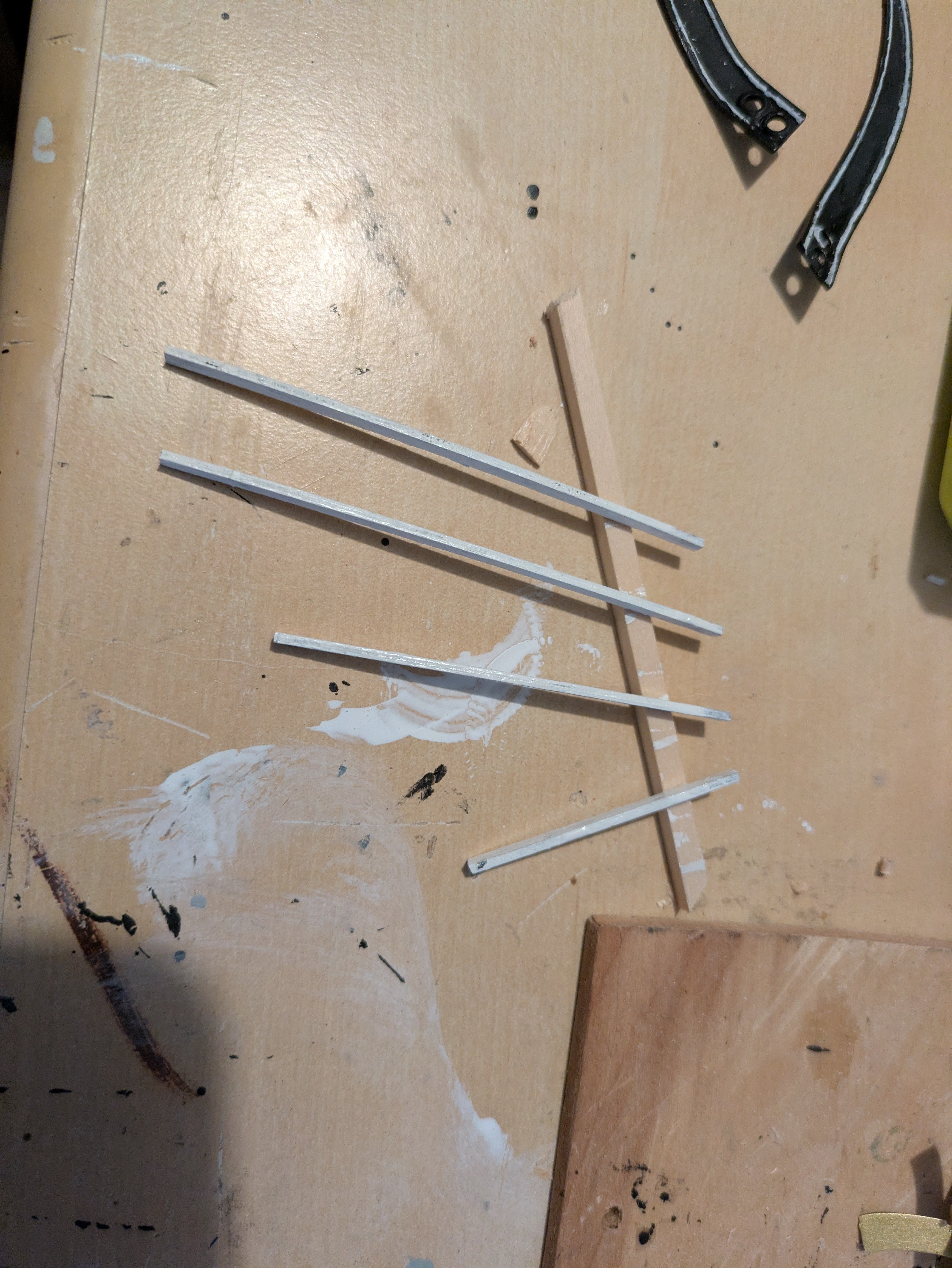
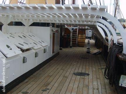
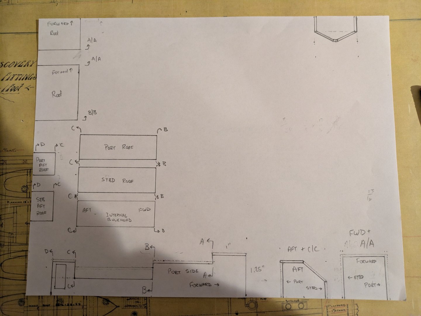
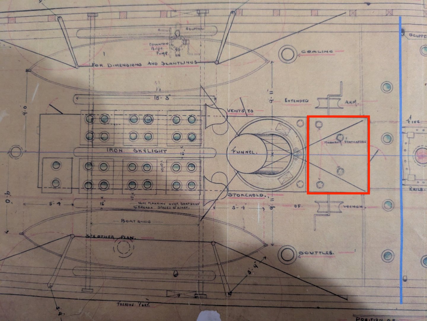
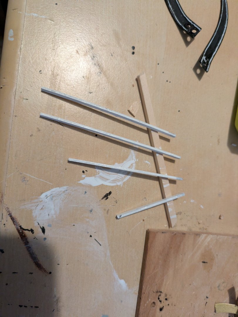
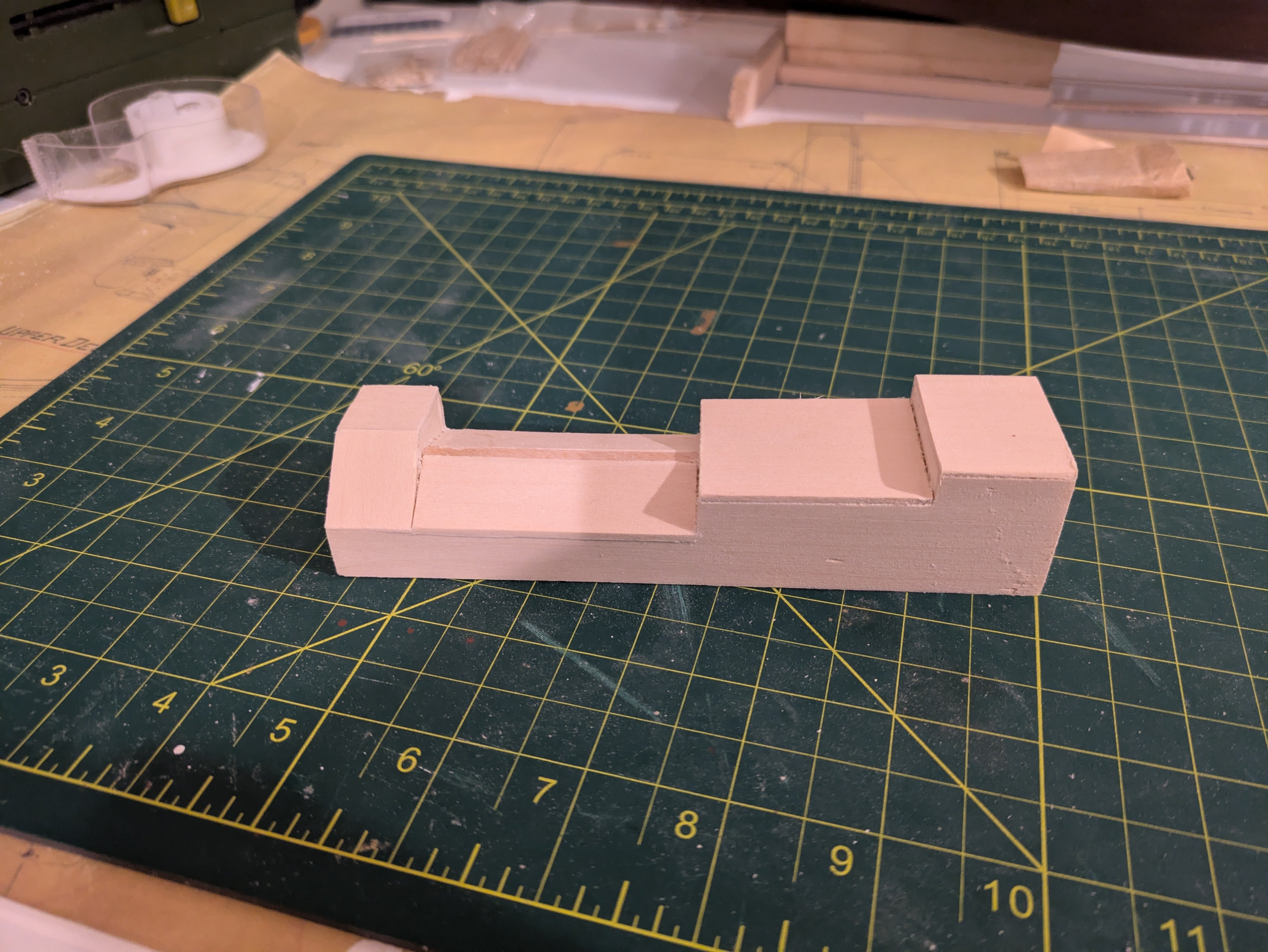
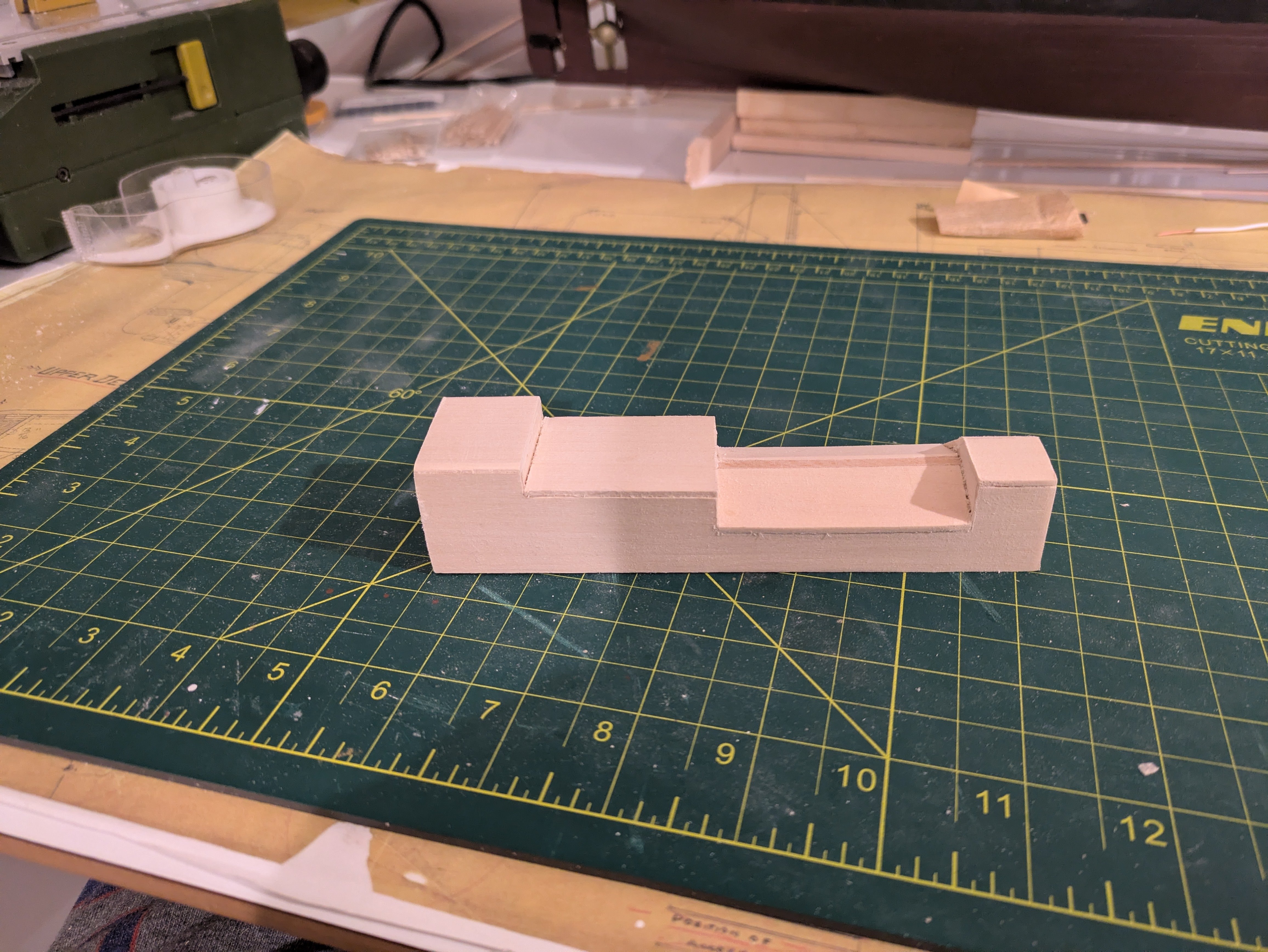
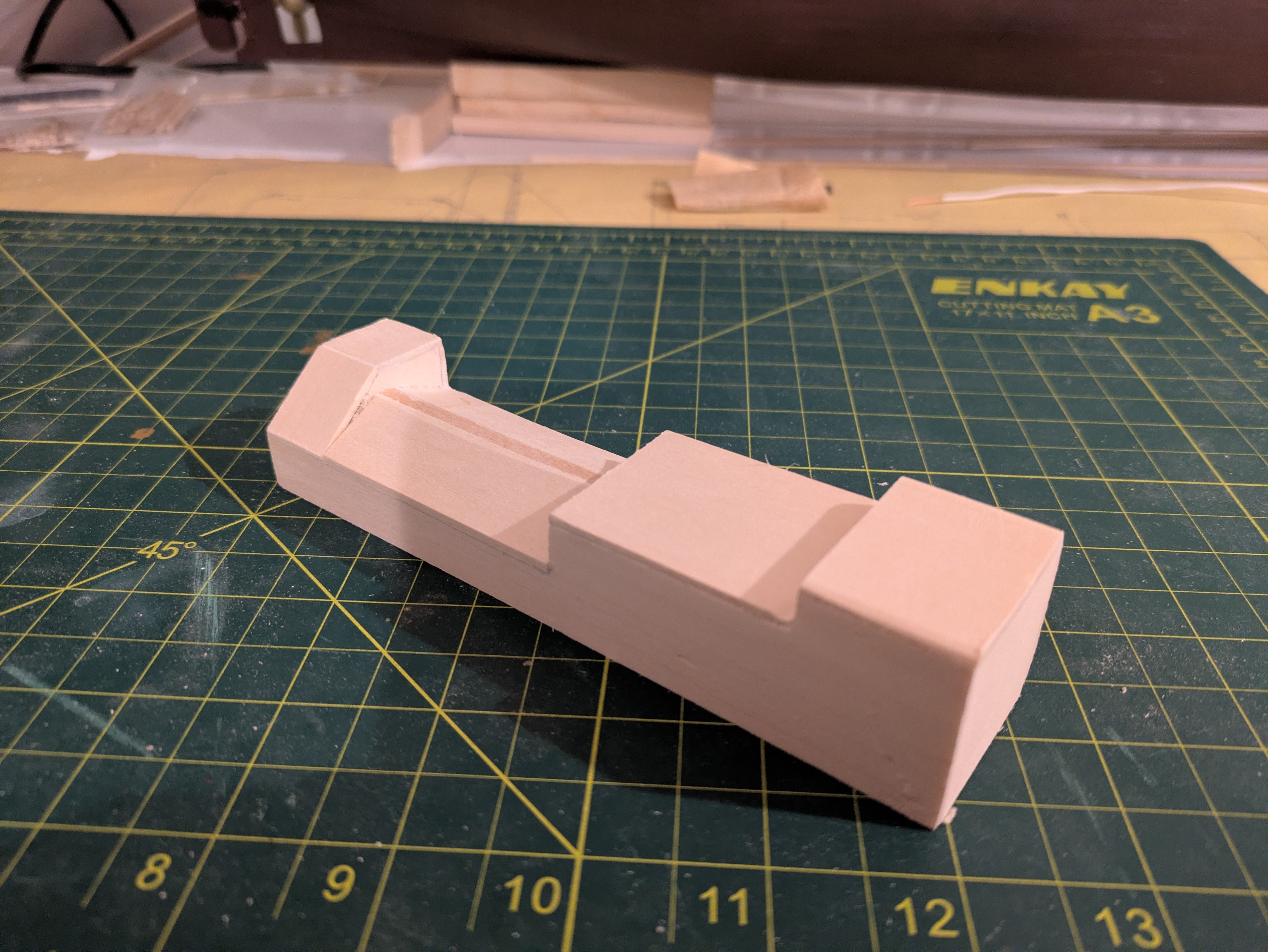
Happy New Year everyone. Back in Cleveland since Monday, so a bit of time to work on the Discovery. Thanks to everyone for the best wishes for our pup. She is doing quite well, despite actually needing to have 3 tumors removed rather than one. She is back to being the scourge of small woodland creatures and I think I may be able to take her for a run soon. I've started working on the shell over the engine room. This is a very complicated structure. Here are a couple of views from the plans. The first is a side view that is pretty much port side only: and from above: Something to understand about this structure is that it is not symmetrical. The starboard side is not the same as the port. The aft port side has a stair down to the engine room from the deck and aft starboard side has an angled surface with a vent (here is a photo from https://aboutaberdeen.com😞 or you can take a look at this video tour (https://www.youtube.com/watch?v=VsotxBpE0Mg). The aftmost vent is different from the other 3 on the starboard side because it goes up to the higher roofline. I should also point out that when the ship was refitted in 1923, it the structure on the ship in 1901 was substantially shortened. Basically, the section shown outlined in red was removed: Presumably this is why the reels are gone. The plans show doors only on the port side, the current ship has doors in the forward (middle on the original) section, apparently both port and starboard, but the plans only show an entrance on the port side, so that's how I'm going to make it. I'm going to keep the knee knocker door in place, presumably that was to prevent cold seawater from getting in and spilling on the engine which would be, bad, I imagine. So, here are the cut patterns for the structure: On the side structure at the lower left, you will notice (a) faintly drawn lines between B|B and C|C that represent the height at the centerline (which will be held up with the internal bulkhead in the drawing), and a line across the hatch between C|C and D|D which is for the starboard side. It's going to be important for those two pieces to be the same. I may try to join two pieces of wood and cut them out together so they match. Once I have two cut like the starboard side, I will cut the port side down to size. The two pieces on the lower right are also being duplicated. The rectangular one will fit at both the forward end of the structure and A|A and the irregular pentagon at C|C and D|D. There is a door in the forward most bulkhead, which isn't shown on these drawings, but which I will add. So, plans made, now time to execute them. As always, thanks for looking in. Regards, George
.thumb.jpg.6c605344dfd62479036718a7f0210552.jpg)

-
Oof. I'll take your word on the placement, but my observation was that the things were a pain to try and rig to under the best of circumstances. I tried rigging the falls ahead of time, but found that when I tried to tighten them down they wound up getting in a serious twist (I assume because of the roll the line was on). FWIW, the easiest I had rigging the things was when a couple of them popped out. I had the holes in place, re-rigged the falls (removing the worst of the twist, put some glue on the eyebolt and then stuck the whole contraption into the hole in the deck. Sorry to hear about this, but I'm sure you will make it look awesome in the end! Regards, George
- 360 replies
-
- 1
-
-
- Flying Fish
- Model Shipways
- (and 1 more)
-
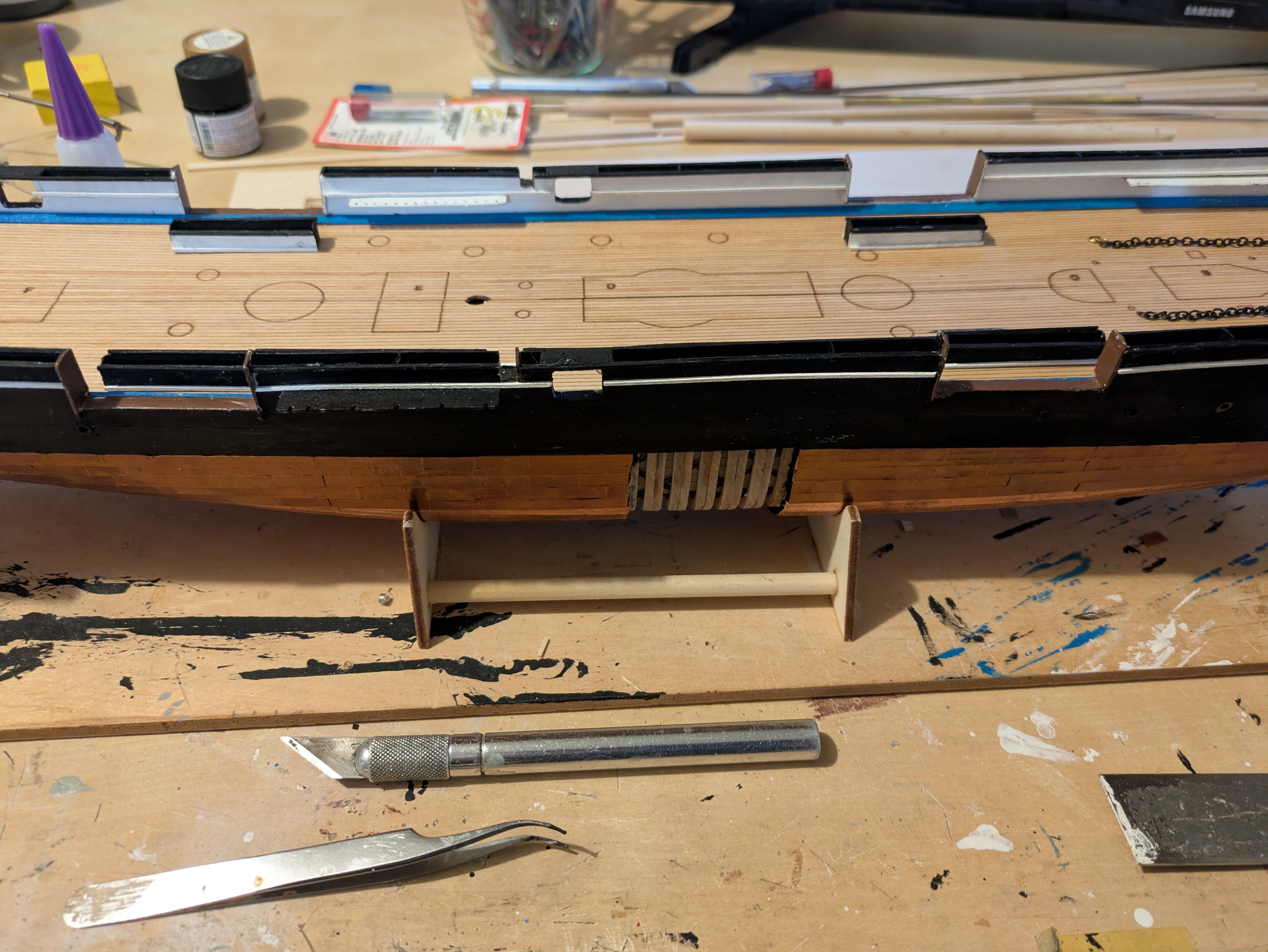
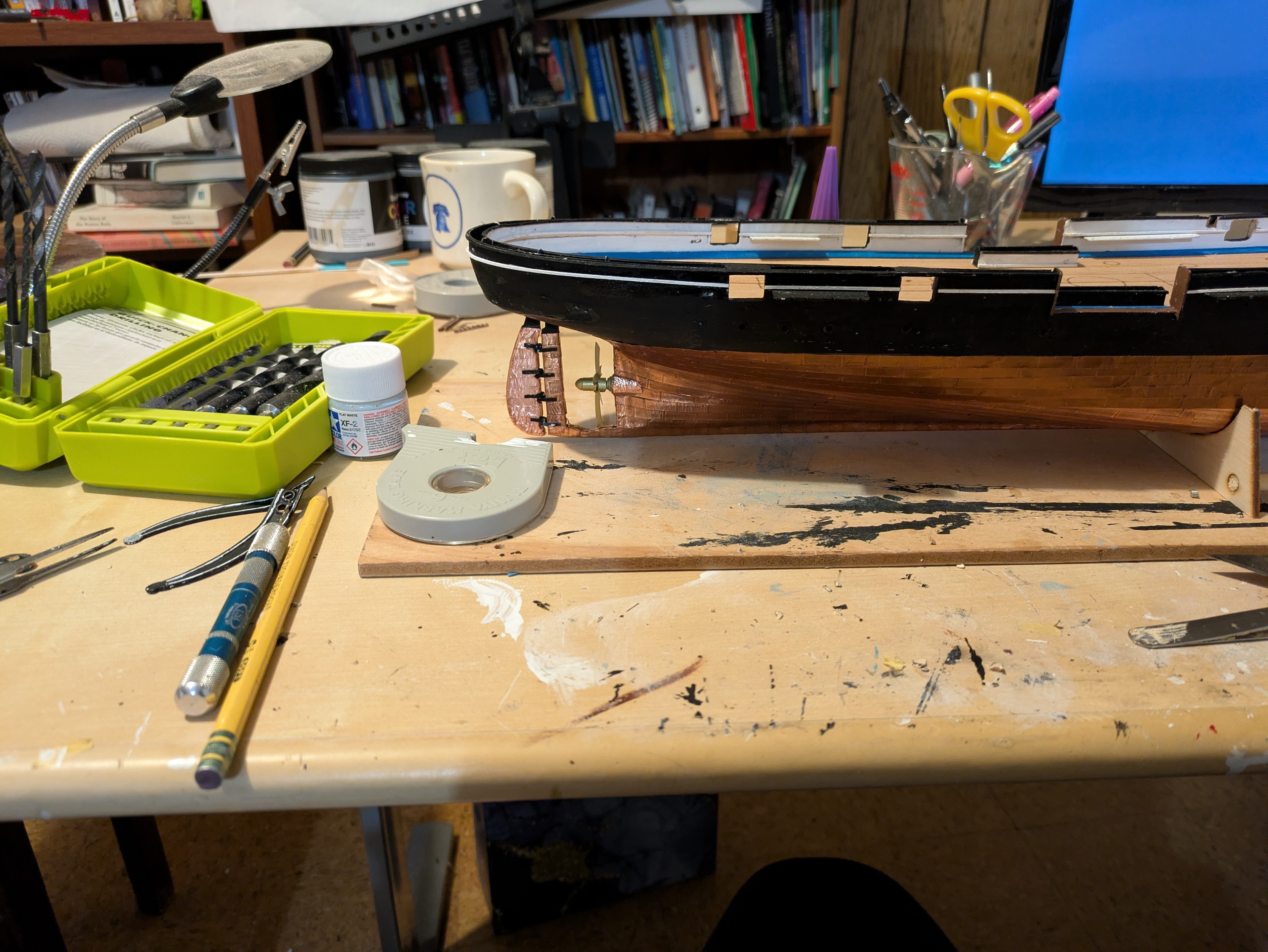
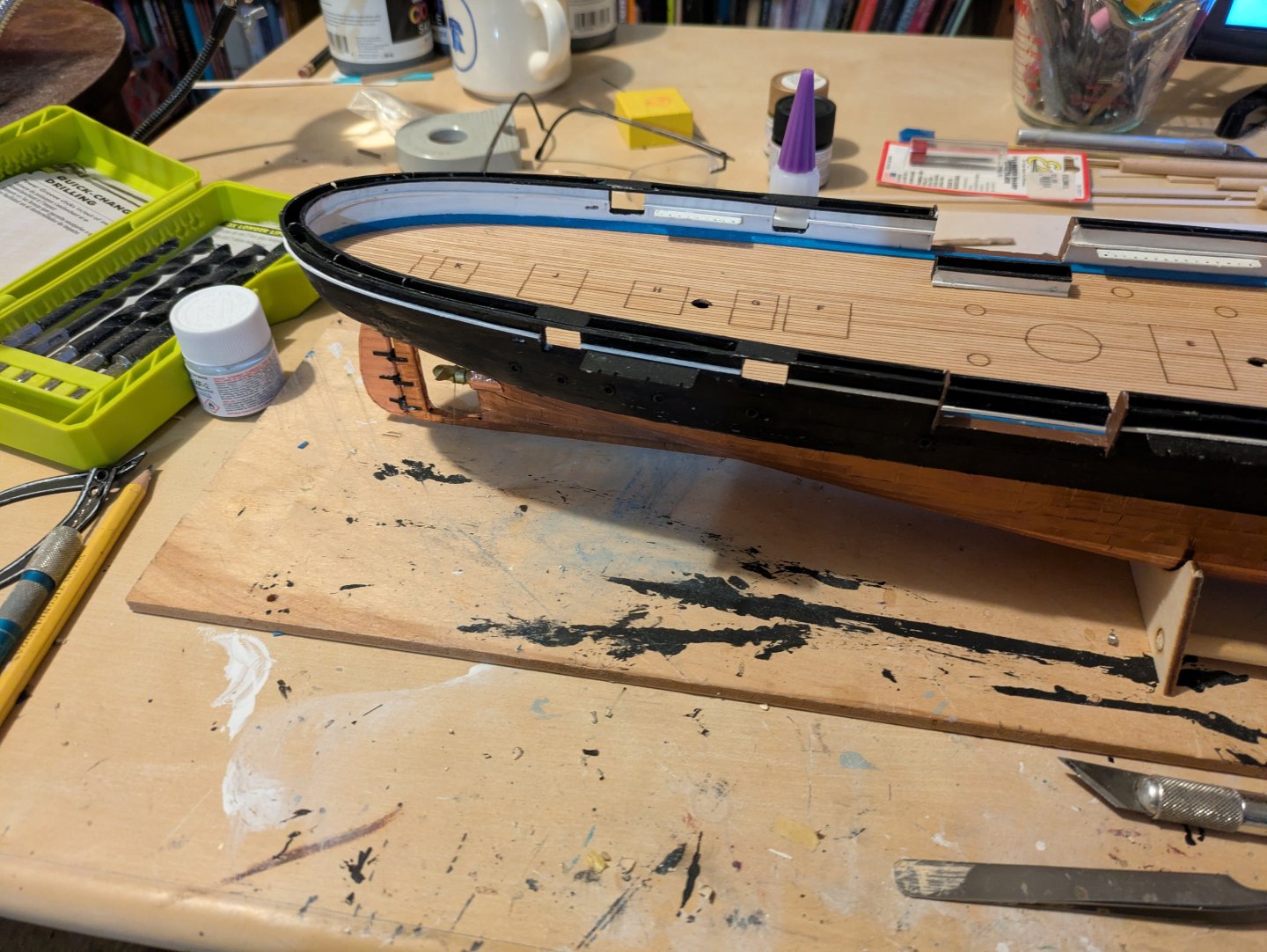
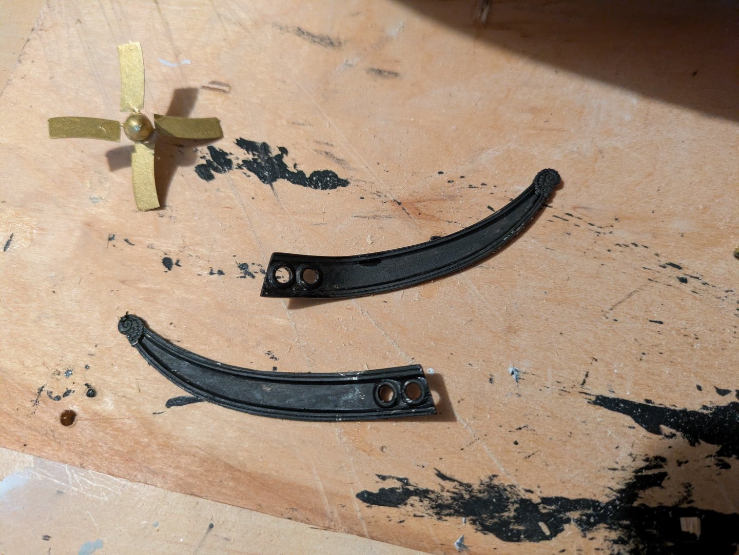
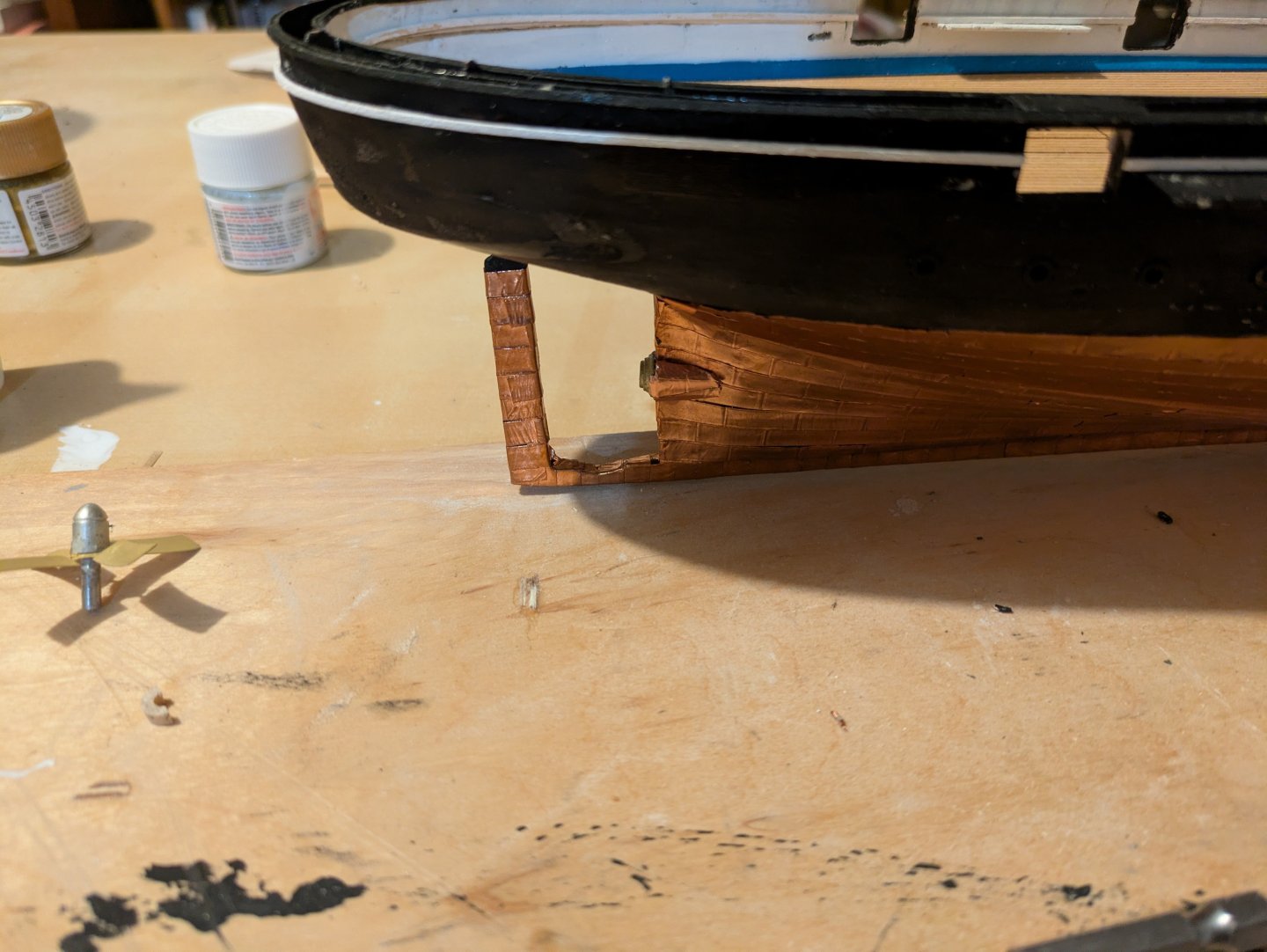
I hope everyone had a great holiday season, however you celebrate! We returned to Rockville for the holidays and were able to see both of our children as well as other friends and relatives, so definitely a success. Return to Rockville also means shifting from working on the RRS Discovery and moving back to the USS Kearsarge. So, updates during the holidays: Forecastle: I built out the forecastle, cut the beams to length, painted and installed them: The waterways did not completely run to the bow, so that needed fixing before the deck was added: And finally, the deck was sanded and jointed so that the seam was hidden, and attached to over the deck beams: Rudder and propeller: The rudder is laser cut, but needs to be shaped somewhat and painted black. I then used some spare copper tape that I had previously marked into plates to cover the rudder until it would match the coverage on the hull. The hinges are made from styrene strip and dowels. They were glued to the rudder and then I trimmed the rudder stem so that it would (a) fit into the slot in the hull, and (b) sit with the bottom of the rudder even with the bottom of the keel. I glued it in place, followed by the gudgeon portions of the hinges. Next, I installed the propeller into the boss I added in the last update. So a couple of views of the ship as she is currently. Aft: Center: and from overhead: As always, thanks for looking in! Regards, George


-
Looking great Rick! You do really awesome iron work and it really shows in these parts. Regards, George
- 360 replies
-
- 2
-
-
- Flying Fish
- Model Shipways
- (and 1 more)
-
Sorry I missed the completion! Fantastic job! George
-
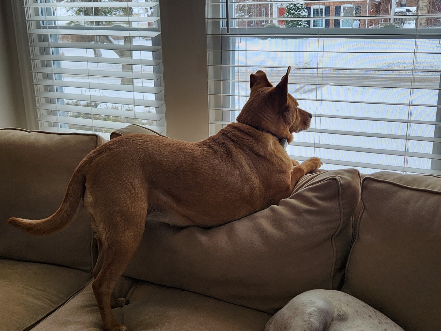
The tumor is in our (apparently) Carolina Dog, Annie (seen here guarding (?) the house in Cleveland. Her brother Hobbes the coonhound is partially visible is in his characteristic pose as well, which is to say, sleeping. They are both 11. So far the prognosis is good and surgery is usually curative on cutaneous mast cell tumors. Since she will be sedated the vet is going to remove a stye and clean her teeth. Suggesting this was quite reassuring to us since we trust our vet and can't quite imagine her doing the other treatments if she thought the prognosis was poor. Regards, George
-
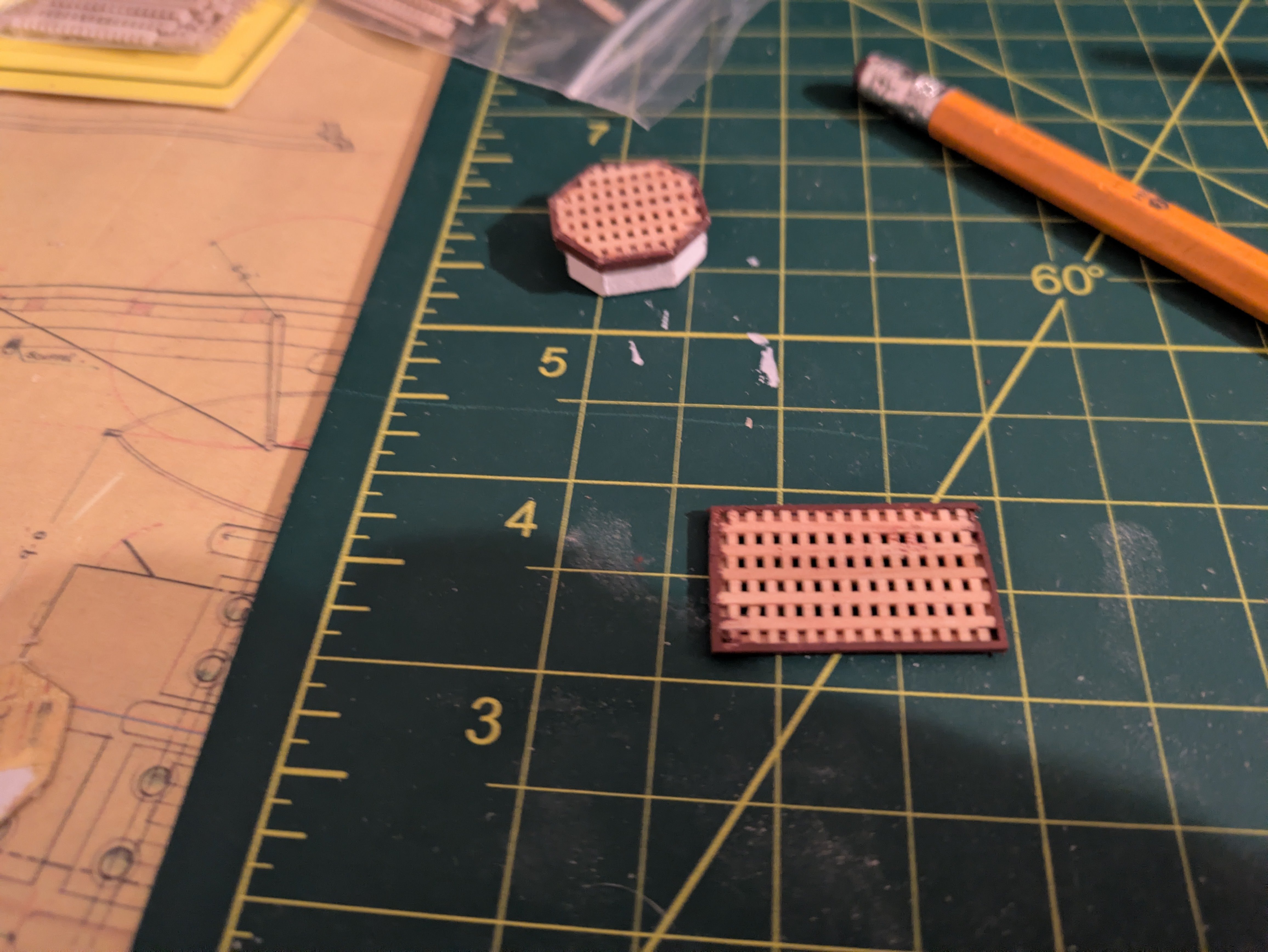
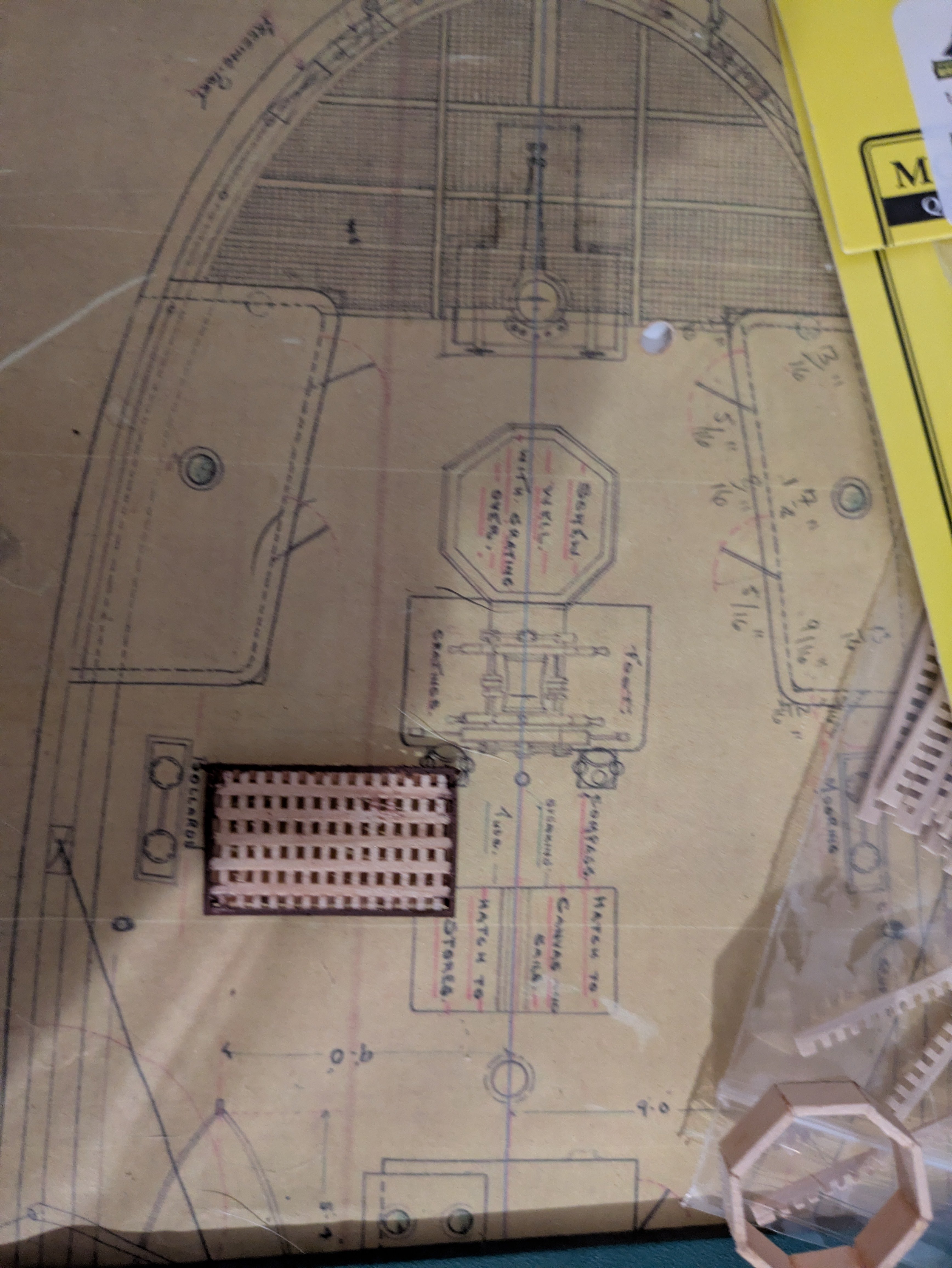
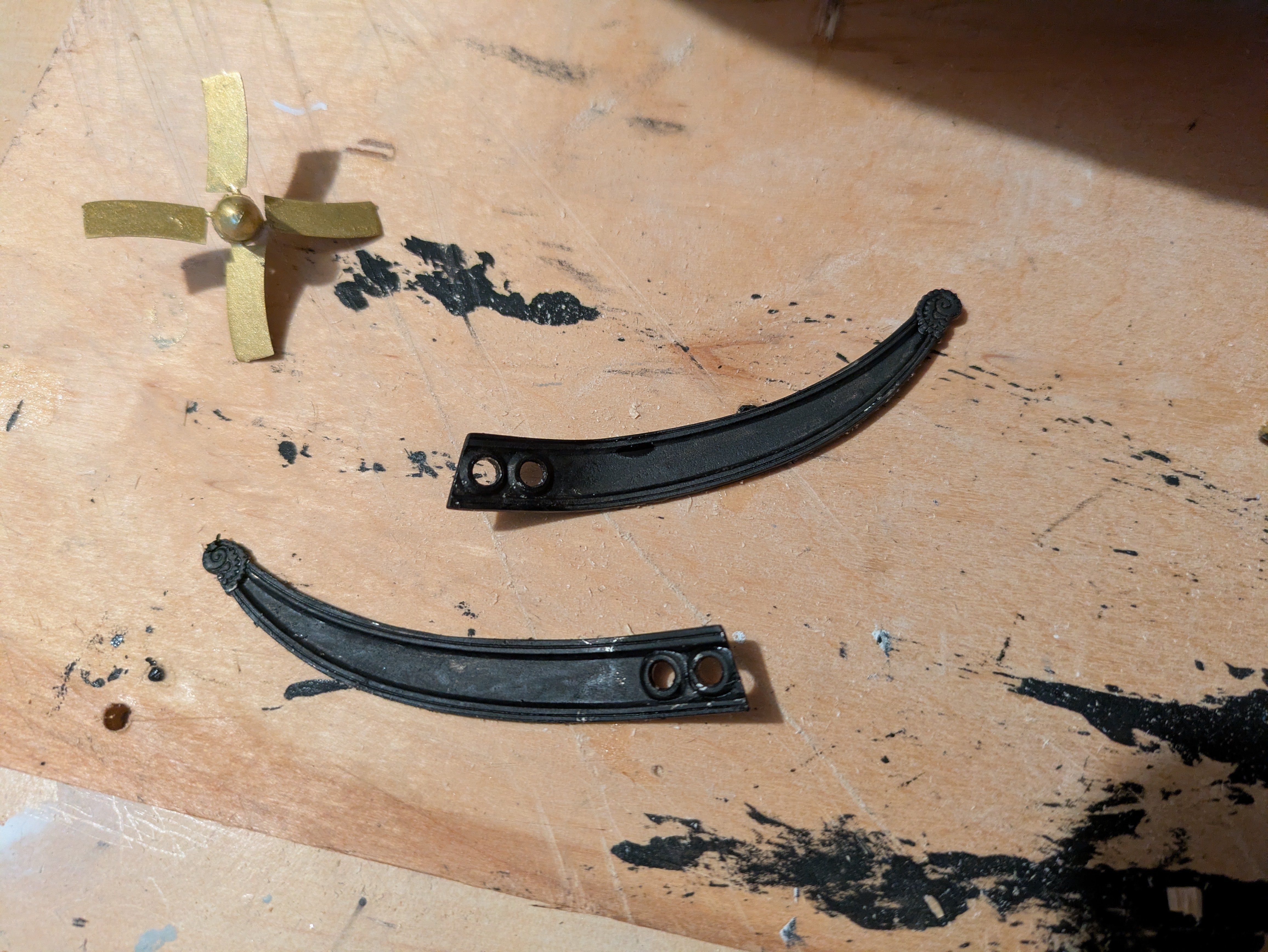
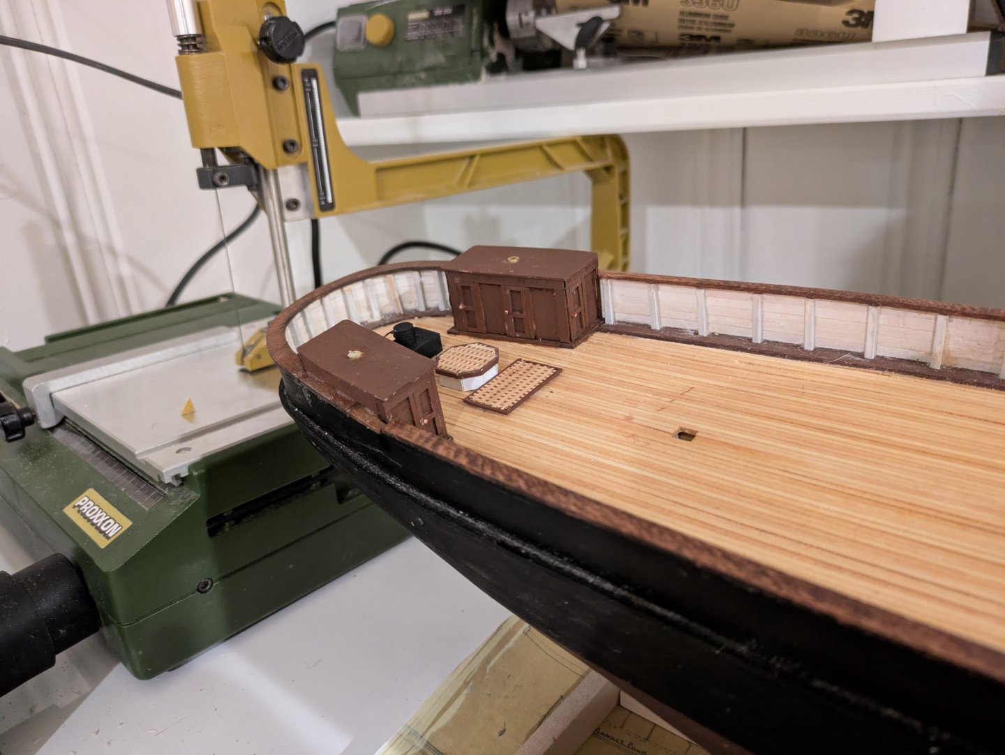
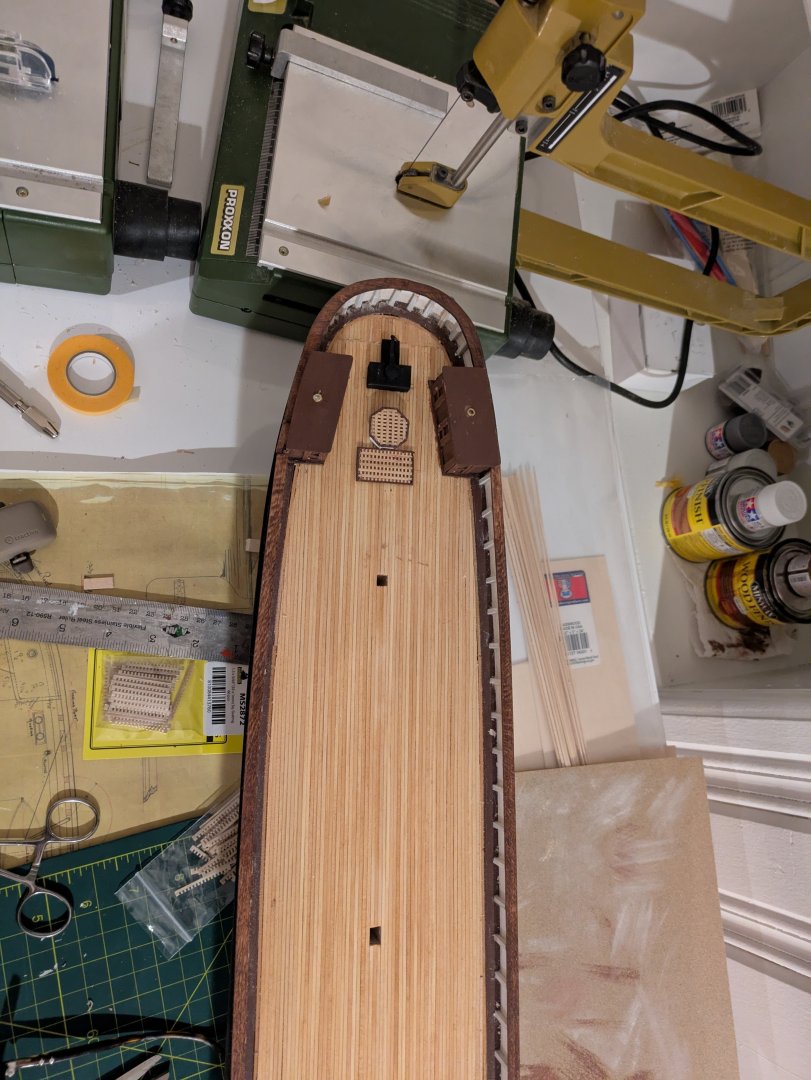
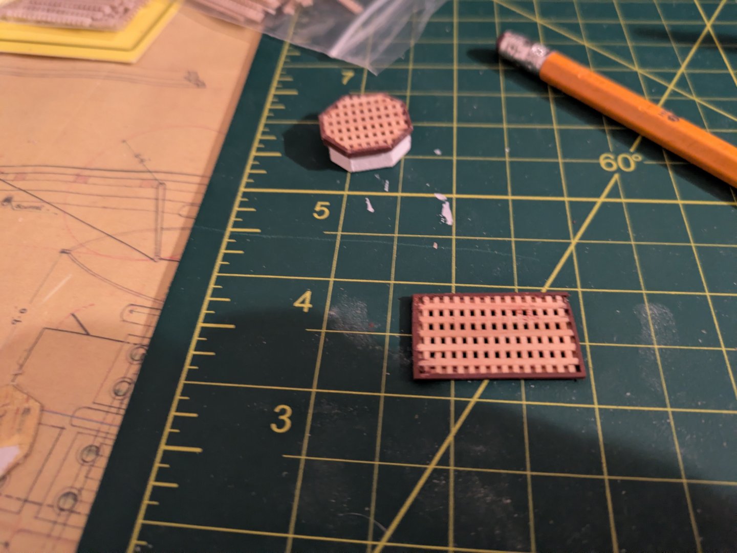
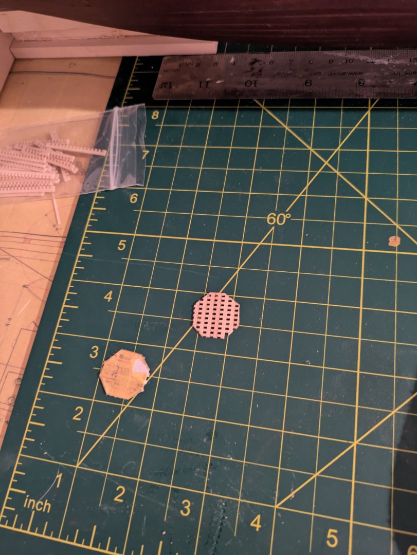
@Canute that makes as much sense as anything I've ever heard, which seems all over the place. I've seen people say that hatches are only on horizontal surfaces and doors on vertical, but in my own experience I've heard people say to "shut the hatch" when referring to a door on a vertical bulkhead. The items on the deck houses open out and are vertical so "door" it is. @KeithAug, thanks! @Rick310, that must've been pretty weird. I wonder if the sailors were creeped out, or if they had the attitude almost everyone does of "well, it couldn't happen to me." Last update on the Discovery for 2025 as we are headed back to DC for the last 2 weeks of the year tomorrow (a little early, as one of our dogs is getting surgery Thursday morning to remove a mast cell tumor). Before turning to the monkey poop, I decided to do some of the deck furniture in the after part of the ship. The two items I worked on were the gratings that the ship's wheel is mounted on, and the well that allowed access to the propeller. The latter is an interesting feature, which in theory meant that they could pull the prop out of the way to prevent damage, and I suppose repair/replace it if damaged. I tried many different ways to make scratch gratings. I can see how to do so, but don't have the tools, and in the end, just broke down and bought the grating strips from ModelExpo. The wheel gratings are just a rectangle sitting on a very thin platform around the edges. It's shown in the photo below. The well is more complicated. If you look closely at the plans, you will see that it is an irregular octagon with 5 identical sides and one shorter and two longer sides. The shortest side is the aftmost face of the octagon. Ultimately, I built out a rectangular grating using the ModelExpo strips, cut out the octagon, centering it as best I could and stained it as per below: I then took a 1/32" by 3/64" square piece of painted basswood, and wrapped it around the octagonal grating. The painted piece became the part of the lid that fits over the octagonal well. The rest of the well was made for 1/16" by 1/4" basswood, painted white. I cut out each of the well's sides to fit, trimmed the edges to approximately the correct angle to fit, and glued it onto the underside of the well grating, until I had the full octagon. A little touchup and you get the following: I then mounted the steering box (black), the well, and the wheel gratings onto the deck. Here are two views. The first from above: And the second oblique from the starboard side: As always, thanks for looking in. Everyone have a safe holiday season, and a Happy New Year. Regards, George

-
Unbelievable! That is absolutely astonishing work!
-
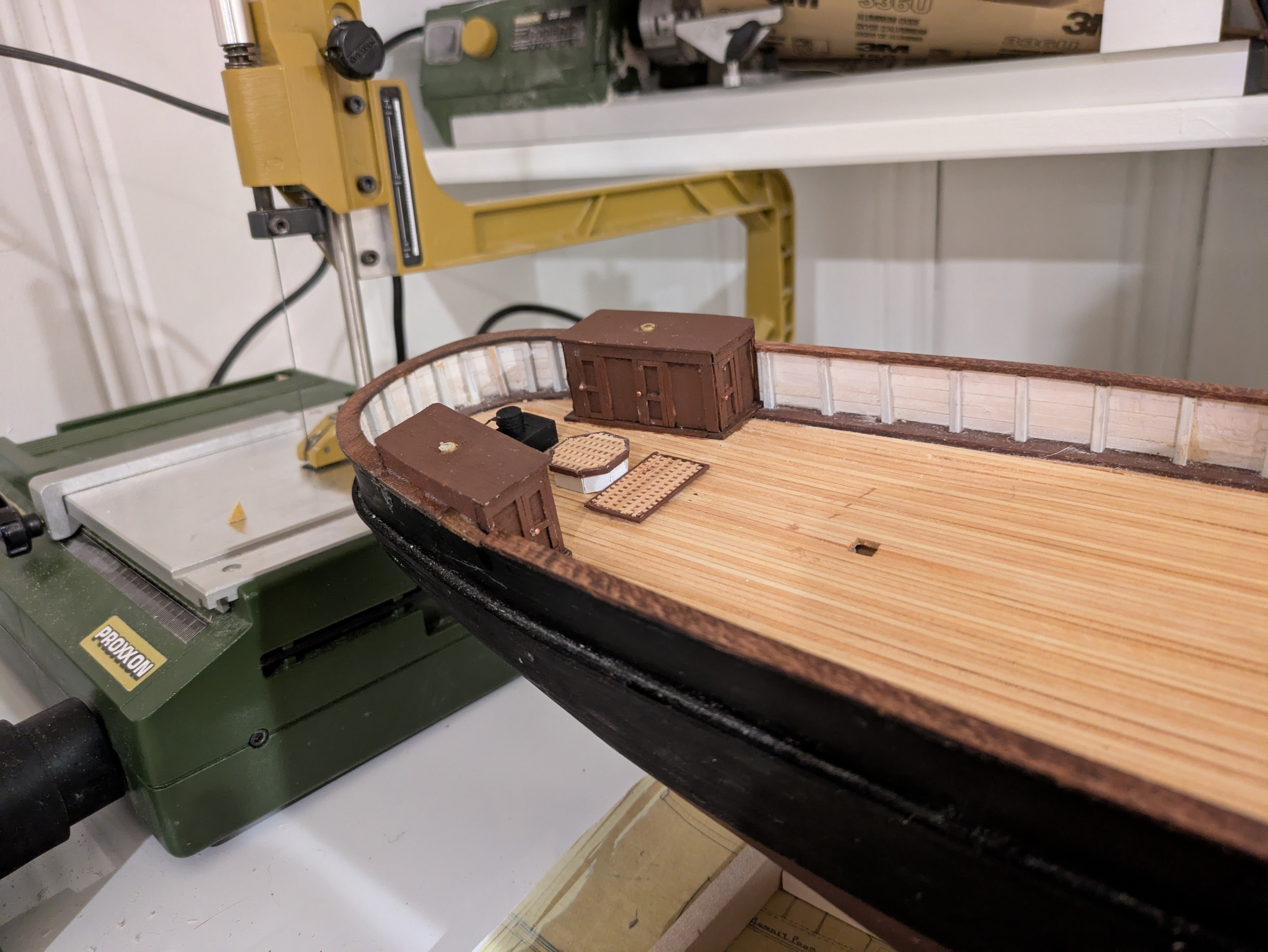
Back in Cleveland, so that means work on the Discovery continues. So here are a couple of pictures of the painted and installed after deck houses, minus the overhead which needs painting and a few details. The doors (hatches seems wrong somehow) will eventually get knobs, but probably not until the new year as my stash of tiny nails I tend to use for such things is in Rockville. The steering box (black) is not yet set, I want to make sure that I didn't make a mistake that will cause it to interfere with the monkey poop before I glue it down. The overheads have a skylight. I made the skylights out of 4 mm styrene tube, painted and then filled with CA glue. Here they are on the plans with just the drilled hole: And then installed on the deckhouses: And two of the ship with the deckhouses in place. One looking aft from amidships: And one showing the whole ship from the waterline: As always, thanks for looking in! Regards, George


-
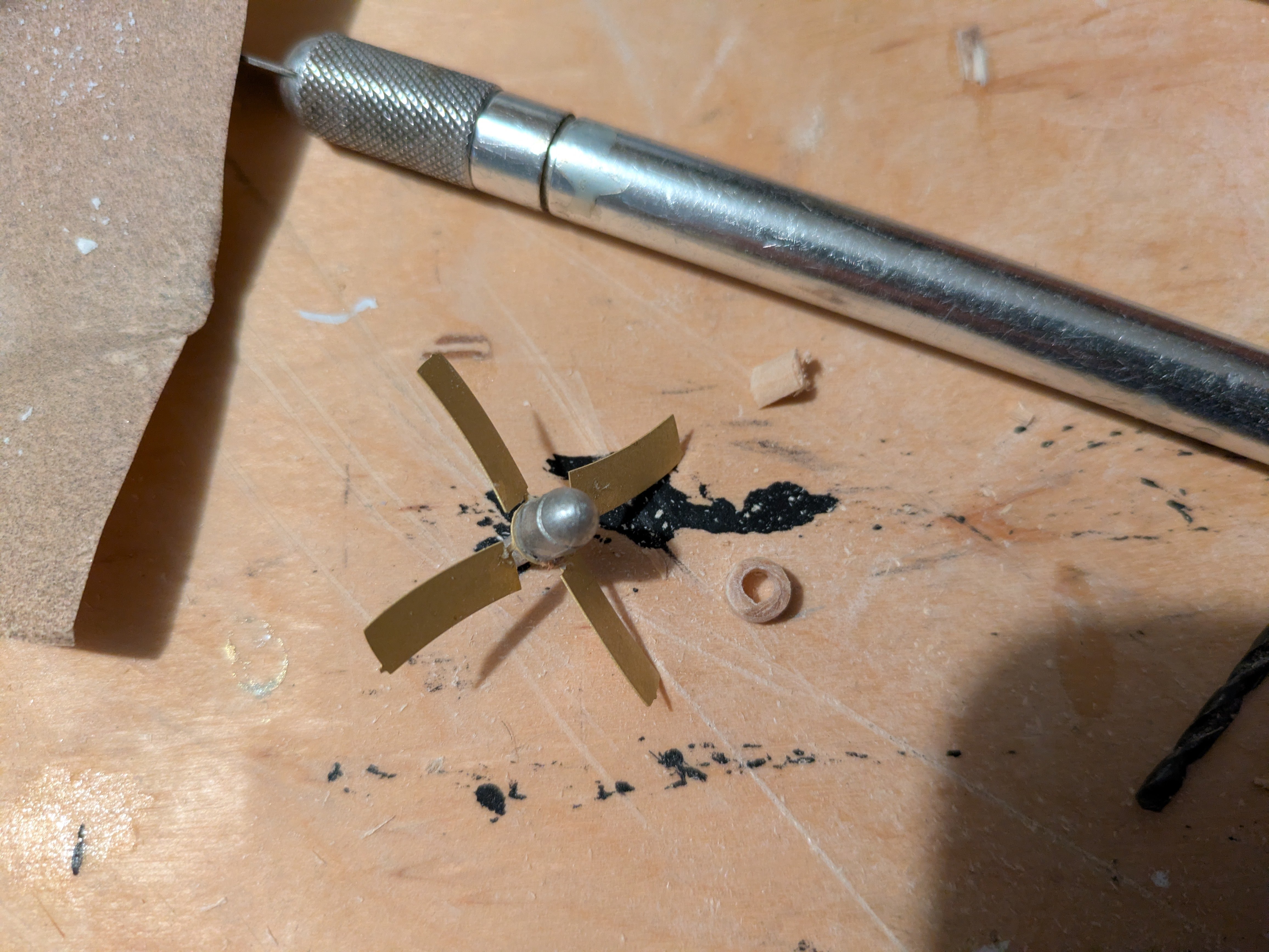
One last update until mid-December when we return to Rockville. The missing piece that I needed to make was a ring that wraps around the cast fitting that is the prop. That's the small wooden ring that is on the right side of the image below. I assembled the prop (now that I have the ring) and painted it brass so that it should be ready to fit when I return. In addition, I fitted the trailboards to the hull, opened the hawse holes, and gave them their first coat of black paint. And finally, I manufactured, copper plated, and mounted the stern tube? shaft alley? propeller shaft boss? Perhaps someone can provide me with the correct term. As always, thanks for looking in. Next update will likely be sometime the week before Christmas. Regards, George

-
Looks great Jared, and I loved the Boston Harbor photos!
-
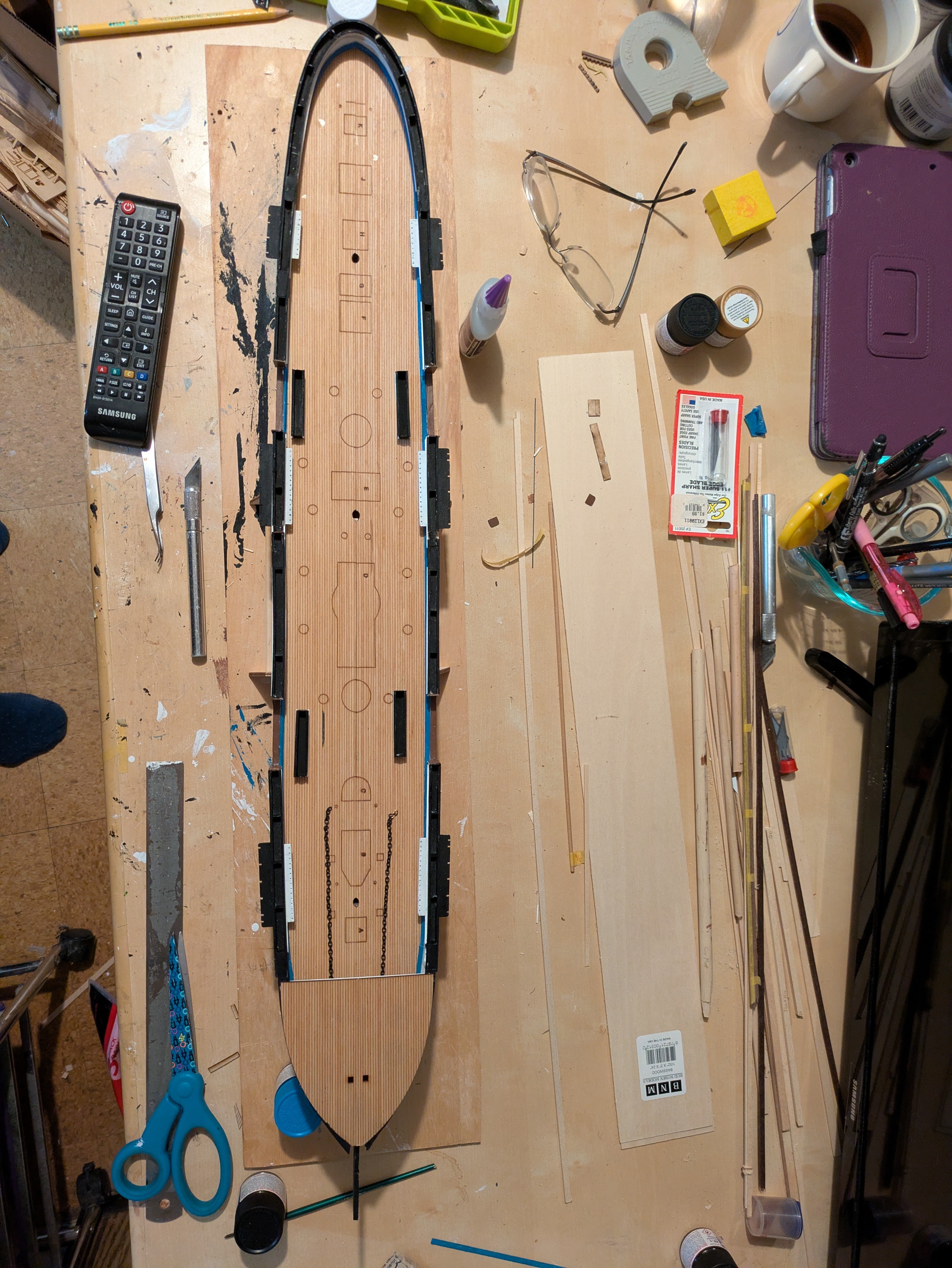
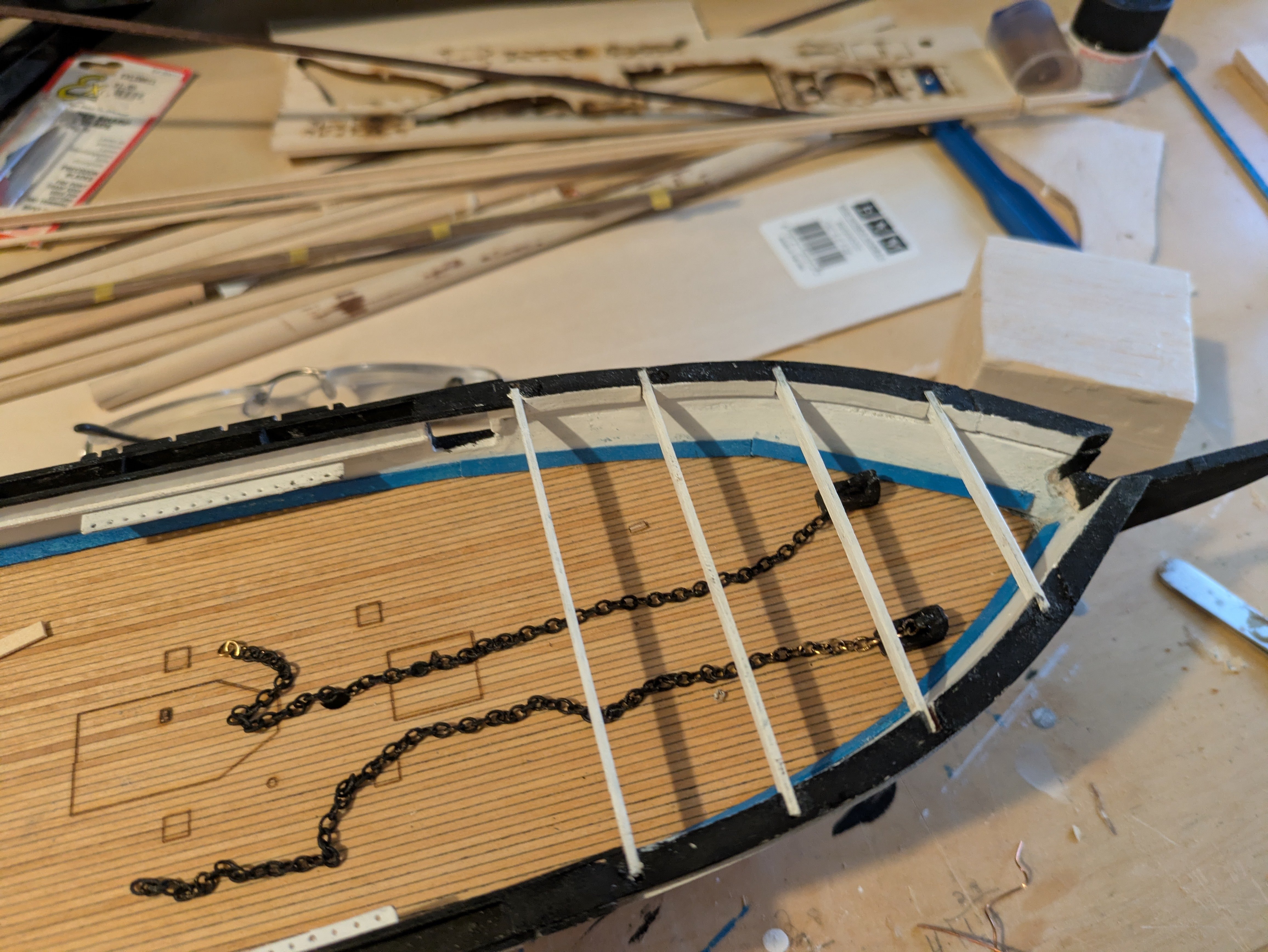
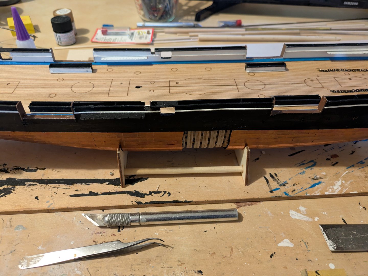
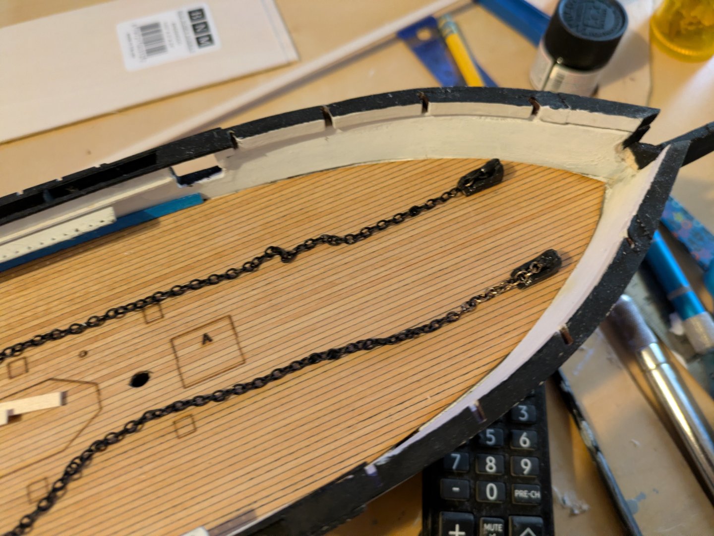
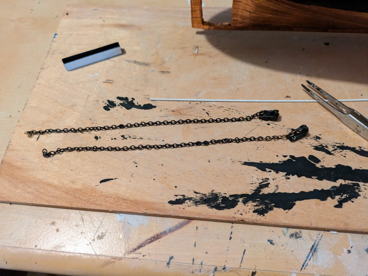
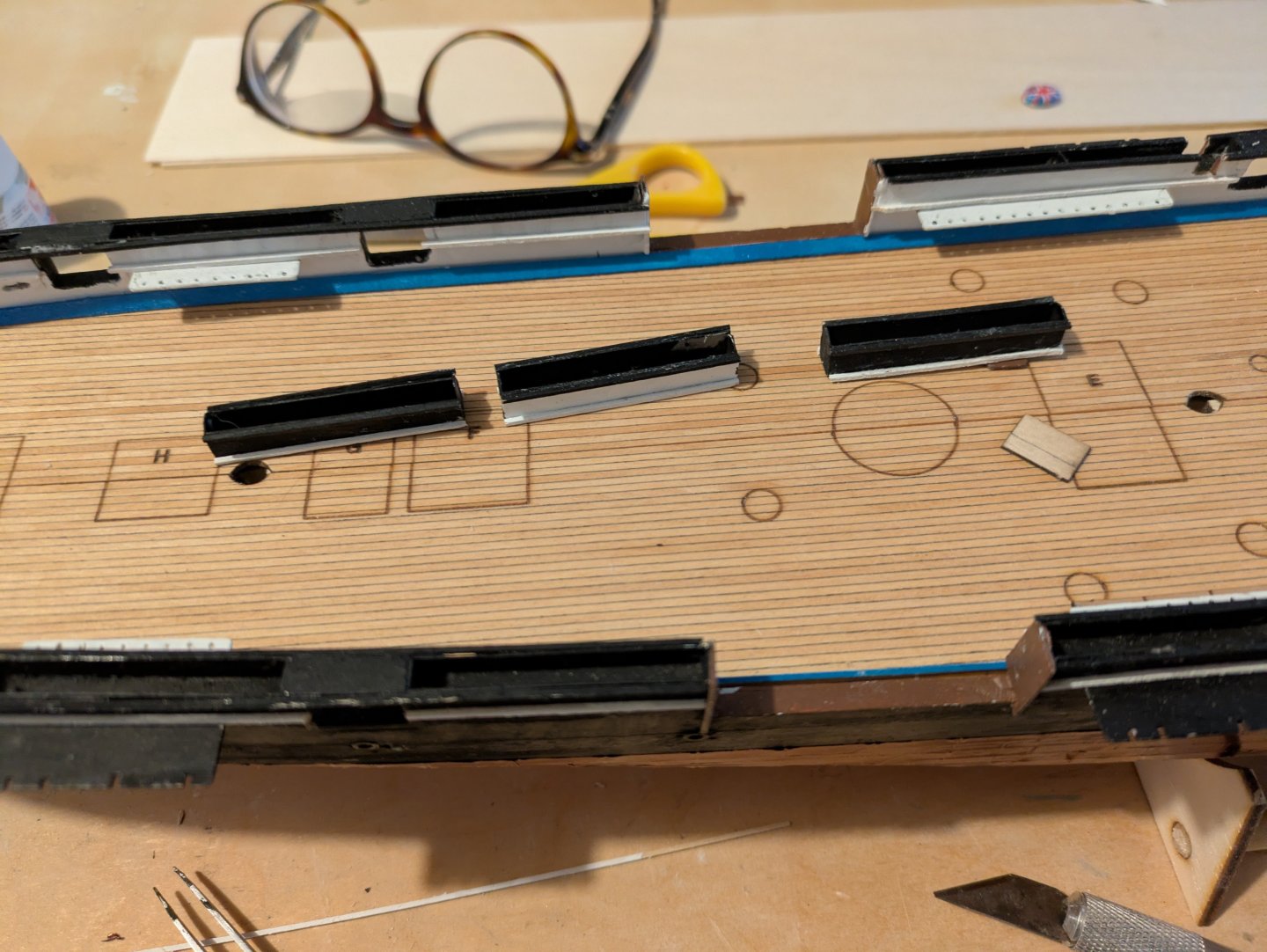
So, it's been a few months since I last posted on this. Those that are following my Discovery build will be aware that in July, I accepted a new job in Cleveland, and my wife and I moved there in September, both age 60. Since then, we have spent about every other weekend in our old place in Rockville, MD due to a combination of elderly parents and some business commitments that my wife has. For obvious reasons, my building during that period was not significant. I split the two builds between the two houses, the Discovery in Ohio and the Kearsarge in Maryland. Things have finally stabilized enough (and we were back on MD for a week) so that I have made some progress. First, the four hammock net boxes that fit in the gunports for the 11 inch Dahlgren guns were constructed per the instructions, and trimmed with 1/32 inch white and black painted stock. Three of the are shown here: Next, I painted the anchor chains and chain stoppers, and glued them , again, as per instructions. ...and installed them on the deck. I was going to mount the prop, but the laser cut spacer part has apparently come loose and vanished somewhere. I will need to construct a replacement with some of my Ohio tools before installing, and, in any case, I think I will wait until I've mounted it on the board I just ordered. I needed to paint some more blue waterways before closing off the forecastle, but it appears that is in Ohio as well, so, that is for the next trip. If I have some time tomorrow, I will mount the trailboards and open the hawse holes and do another entry, otherwise, I won't have anything to add until mid-December when we return to Rockville. Thanks for looking in! Regards, George

.jpg.69238ba79da327e5ec7707e010652030.jpg)
.jpg.00e3530e91a79404e6e391d562a47b25.jpg)