Moony
-
Posts
82 -
Joined
-
Last visited
Content Type
Profiles
Forums
Gallery
Events
Everything posted by Moony
-
 Thanks John, the project gives some interesting possibilitys for exercises to me. At the moment I'm palning th baseboard: Here the rough cutout of the 4mm - plywood baseboard - in some Italian forums thread about a Schiffazzo I found the same measurement for the thickness of plywood used for the same scale). Here the construction of the opening in the base board - and looking for a solution to get rectangular joinings (picture will come after paint will work again): this was the source of my idea: the reason is rectangularity of the soft poplar plywood, a proper surface I could sand and certainly to get more contact area to glue the planks... and I can work with the wood I've already got and don't have to "enlarge my budget" .. any eigth to eight millimeter softwood square sticks will not to be able to buy at common in a DIYshop. What do you think about my trick?
 -
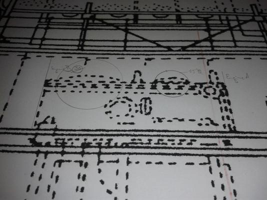
Very nice sideview - but NO scuppers here!
-
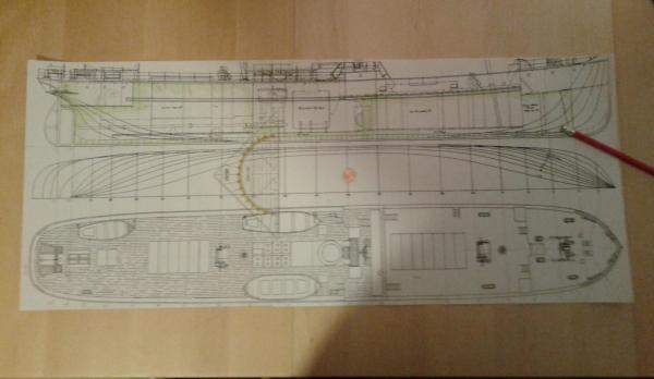
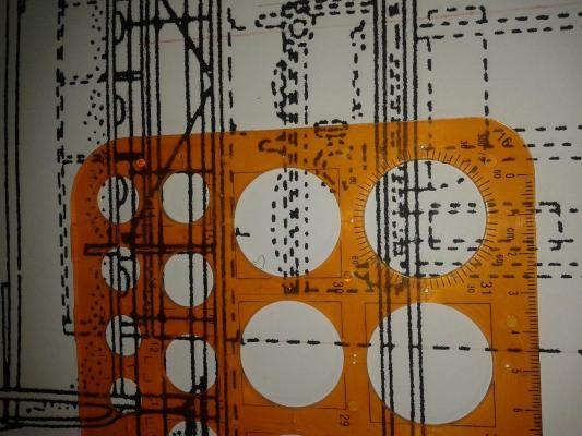
Here the view on plansides and some details: and at the very ed the proof of scale: not 100&% but close eough to the 1/50 I wanted to have... the paper is working in the copyingmaschine a lot when drying in the haeter to fix the toner.
-
Hello friends, as the S/S Warkworth costs a plenty of mindwork I decided to add a second project less complicated and time consuming. So I leafed through the plans I've stored and found some very nice old "chances" but mostly the were to complicated and sophisticated as a "sidecar-building". So I figured out the exercisebook sized Modelarstwo Okretowe Special No. 19 of May 2015: The prototype is a Sicilan/Southitalian Coasting boat of the 1860th with a length between 15 to 20 meters and a 1/3 Length/Breadth ratio. Here a pencil drawing I found several years ago in teh web - I think on an Italian site. Here well to see the line of scuppers on the underside of the bulkwalk. The Lauretto was used for short sea trades and a fasr as my Latin knowledge translates some Italian websides I figured out thet the latin-rigged boats made also journeys to the North African coast. So this little ships were used in transport purposes and fast and handy ships to sail. It looks like the were used in transport of general cargo in sacks, barrels and boxes - no bulk cargos seem to be stored under the hatches. I couldnt find out what are the diffrences and relationsship features to the also latin-rigged Schiffazzo - but there were both: similaritys and diffrences. But let stay us with the Lautello in exspecial the "after castle" that is not found on the threemasted 1 Schiffazzo -here scale to 1/50; As you can see from the MO-issiue's cover the hatches are closely covered - the plan gives us a grating hatchcover all over here. The plans delievered with the MO are allways very good and they have got a fantasic price. I was able to enlarge the hull's drawings up to 1/50 and so I can start with the work very fast - hopefully some more knowledgeable of you may help with further and deeper information to this article. Next stop: taking photos of the enlarged plan. 1 edit
-
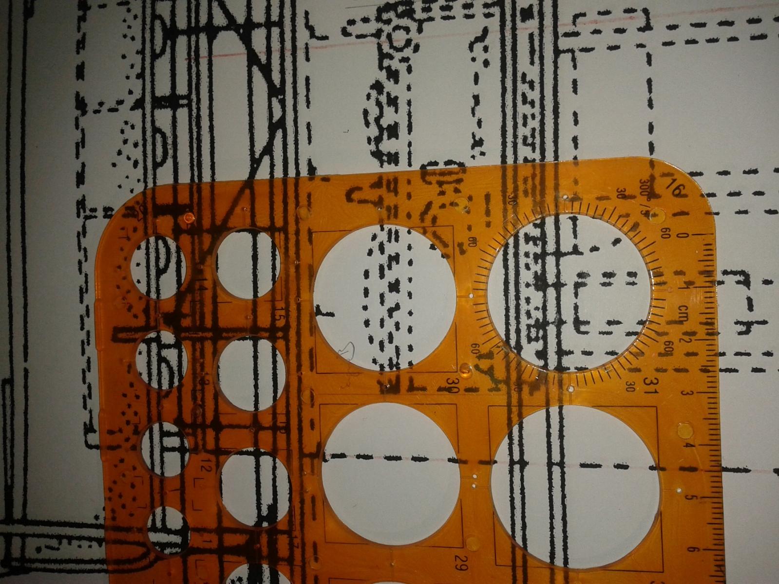
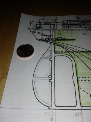
Here I foud what Ithought it was lost: ad it looks very well: and lets crosscheck: 304.8mm for a foot brought to scale by deviding with 48 gives 6,35 mm to us... multiplicated with 5 we got 31.75 mm ...but so the job I gave to the guy in the copyshop is now prooved to be devastantingly realised - and I can't change it for a right done one!!! Now I can go there and I'll have to redo this work on my own.
-
Okay We have got a Breadth moulded from 27 feet (page 1 #1) when we multiplicate this with around a food of 304.8mm so we get 8,229.6mm so we start to devide this through our scale ratio of 48 so Sesamstreat's Count will teach us "So we'll get 171.45mm at the very end!" But! So I do't trust myself to sit an a toilretseat i the right way!
-
HyTadeusz, That looks great, good progress - can you show us a little bit mot of the how vou gozt from he plans drawing to the bulkheads shap you used at the end? It's important for me due to the open hatches, stairhouses and skylights you can look inside the ship. I'm looking for further progress and sending best wishes from Berlin,
-
Here a contemporary picture of a staemer - point of intrest for me is the canvasing of the flying brigde:
-
Hello, after several month filled with job, illness, divertissments (i.e. addtivly kitchen furniture manufacturing ) and some of trials of redrawing I can now bring some further news during the next days... I was very happy to find a yard model of S/S Warkworth... also something to do with Newcastel on Tyne and she was a singel screw steamship ,too. Source: vallejogallery.com but it was her a later bearer of the same name... So let's look forward to the awaited progress: new Mr McSale in 1/48 trial of the deck's beam stencil redrawing of the formers Hope you all are well, Yours
-
Hy Maury! That's a fine example of some so often neglected working craft. Perhaps somebody is going to copy it, placing it beside a warship in some diorama to show it at work. Thanks for sharing. I'm looking foreward to your progress.
- 525 replies
-
- 3
-

-
- anchor hoy
- hoy
- (and 1 more)
-
Ian, your argument mad me thinking if the procedure would make sense... as I used to ask: a ) Why should we act in this way? (Is it done in the most secure, effective, fastest & cheapest way?) b ) Why should it be constructed in this way? (Does it fit in the place it is put in - i.e. Does the crane collidate with anything in its pivoting range?) bb ) Could it have been constructed at this time in this way? (Ancorsteamwinch on deck of the Victory!) c ) Does it make sense to work in this way at all? (i.e.: May there have been an ash hatch running comfortablely beside the boiler down through the doublebottom right into the sea not annoying any 1st Class passangers - as they may have used it in boilerroom No.1 on RMS Titanic? ) On the side of the furnanche openings there were no hatches - the only openigs up through the deck are the vents... and nobody (i.e. engeneers!!!)) would like the ash to fall on the oily engine when brought arround the boiler to be lifted up through the skylight of the engine room. What do you think is my idea right?
-
Thanks for your answers & motivation power giving within towards me, guys! But as I told you still in the 20th and 30th it was done like this in older coasters not having added with a special ash hatch to cuck it outboard through the hull's side. I'll figure out the exact page where I read it - it is allways the same, isn't it? You know it, You know you read it, You know the book you read it, ...but on what page or in what story this special factum was told to you? You can't remember...
-
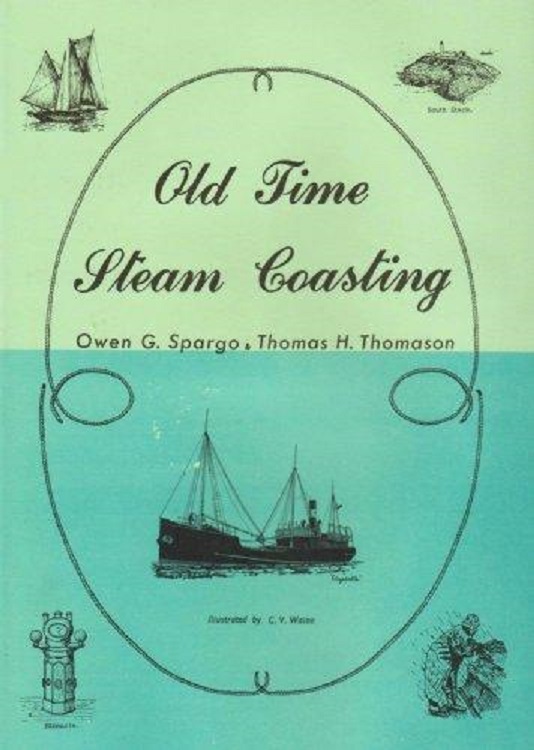
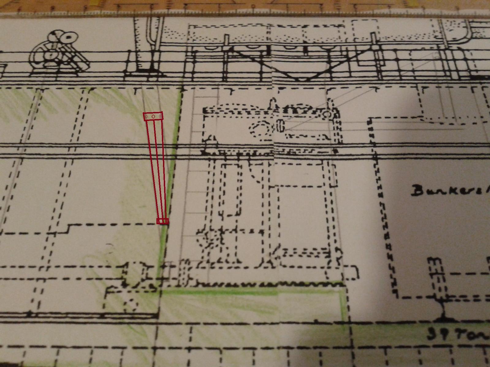
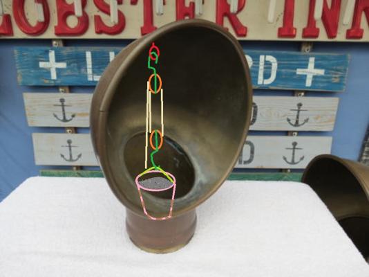
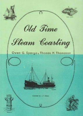
At the moment I read "Old time Steam Coasting" by Spargo & Thomason with a good benefit to several details of the boiler or engine room and to the accomodation in coasters. So I figured out the in the pre 1900 coasters the ash was brought out of the boilerroom by adding it into a bucket . And lifting it to the deck through the vent by a winch. So there must be a hook or eyelet or dee to suspent a set of pulleys in the top of the vent's inlet... So what do you think about my here added my 1st scetch?
-
Hy Mark, thanks a lot this is very helpfull - I was so preoccupied by the decks rounding that I didn't answer - sorry for this! When I assamble the new sawing blade hopefully everything will be easier.
-
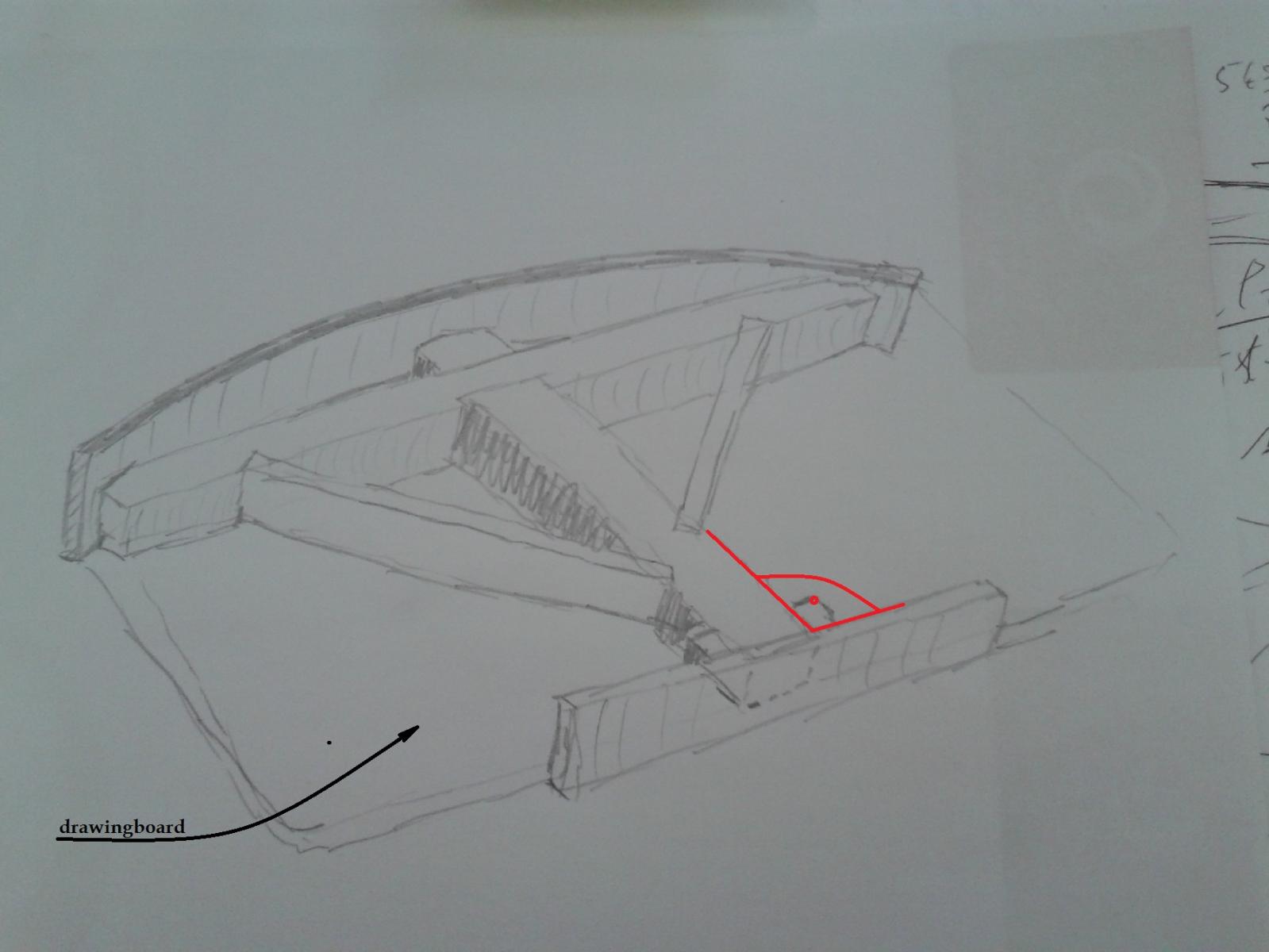
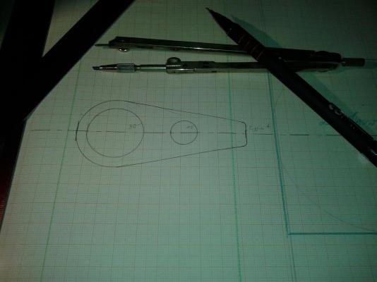
Hello followers &;friends! At the moment I got unlucky with my results and didn't shiw anything to pubicity. I put two sets of former plans to the dustbin due to several failers in the decks bow. It was not parallel to each other, not rectangular to the CL, and so on... so I got more and more frustrated... Ti keep it short&simple: The bending of the deck I tryed to draw in the formers with a curved ruler they don't fit good. Edit: I'll place two drillings for crosshairs to aim for the CenterLine precisely. So I'm going to start to build a "wooden decks beam ruler" fitzing my drawinboard on myself. Here today's first rough hand scetch:

-
Hy mtayler, that's a good idea. Thanks a lot. I'm affraid of breaking out the outside layer if the playwood. I'm not really goid with wood these days. But I'll try out if it will work. It may need several ways if repested trying. Thanks for your comment.
-
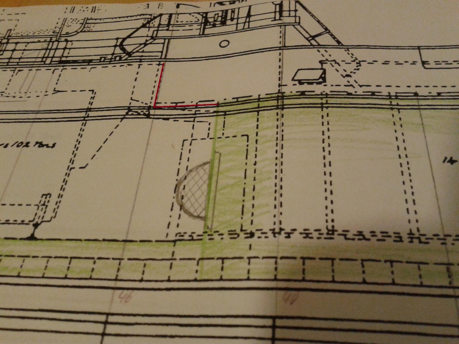
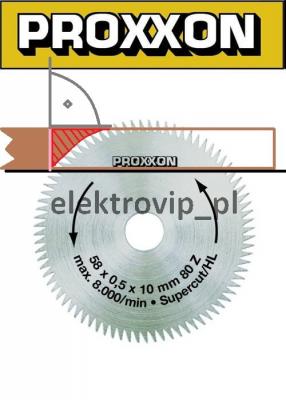
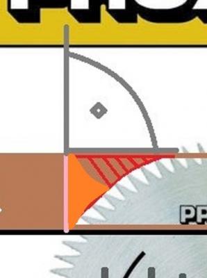
When I started to cut out teh first test bulkhead I realised that the mortice in the bulkhead and in the middleboard should end in a rectangular cut - as the pink line shows... but it endet in the red line... and the red hachred part is a surplus standint in the way... so what can I do? When I turn the bulkhead over I'll get an orange mountain in the middel... What is your tip for using a KS 230 by Proxon in the right way?
-
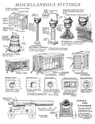
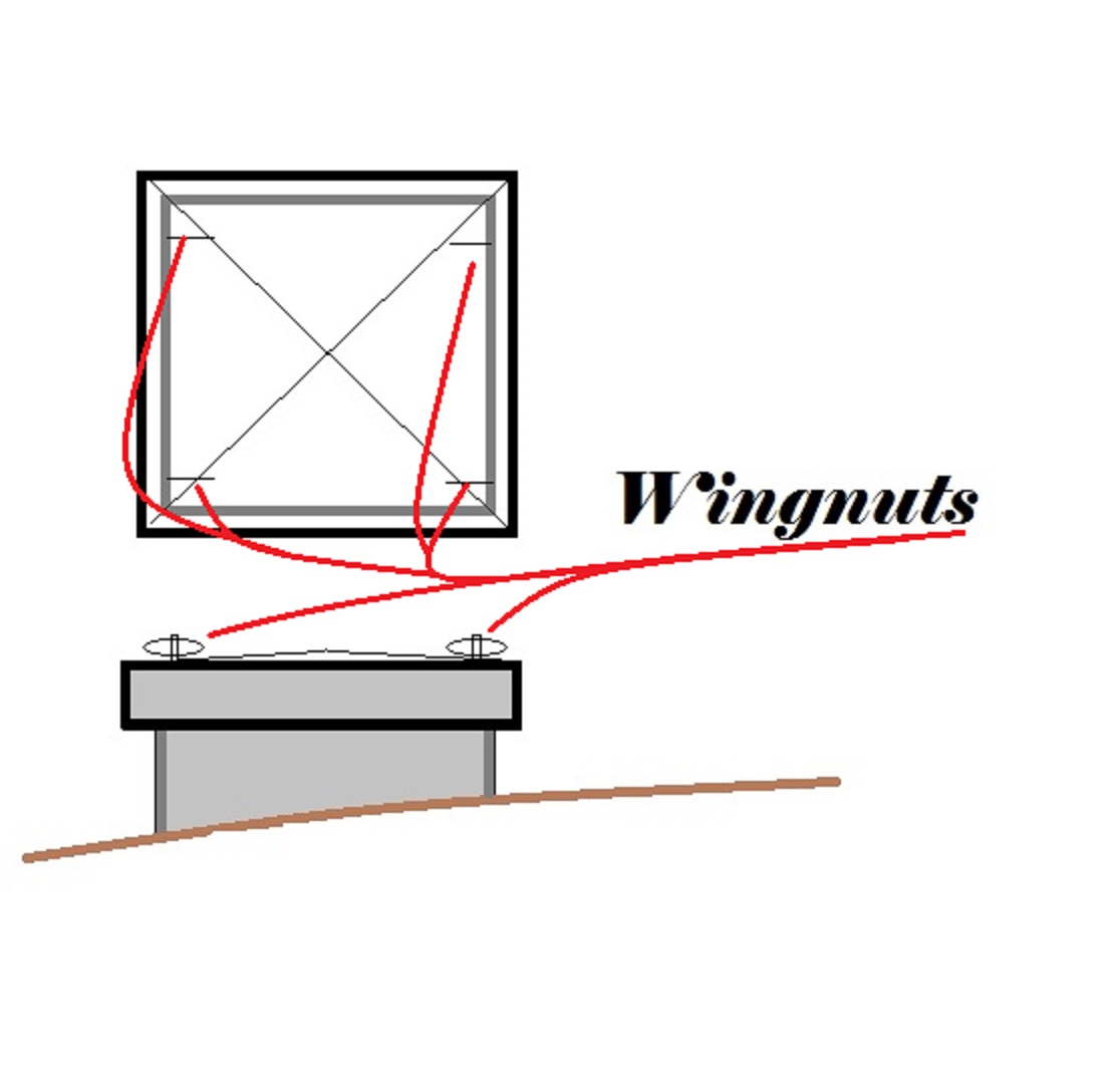
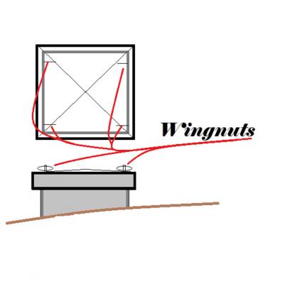
Here my first trial in the hatch of the coal bunker filler. Is this a reaklistic design with wingnuts? I didn't find any real designs in the web - exspecially contemporary... the best example I found where from S/S Kronprinz Wilhelm - a four funner greyhound of the North German Llody -. a vertical type and a quarter of an century too late. Does anybody deal with C.S.S. Alabama oder U-S-S. Keaserage where I may find some good example?
-
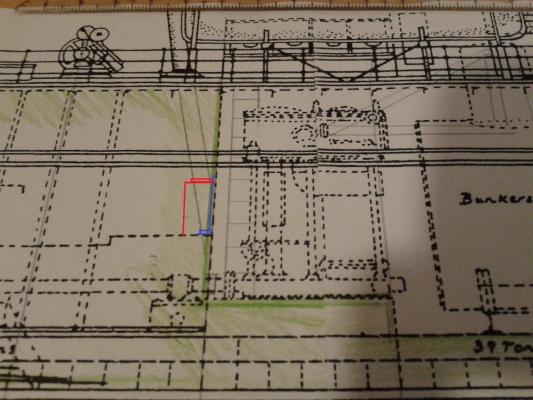
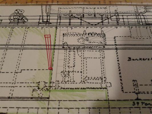
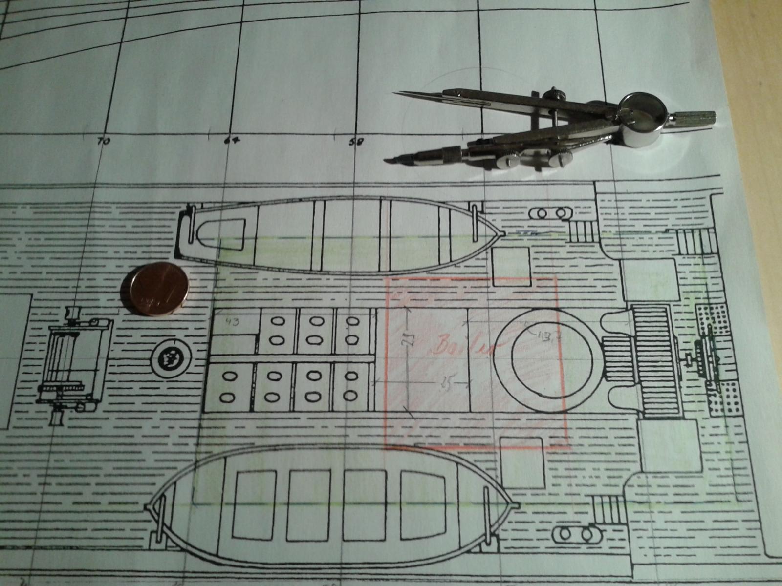
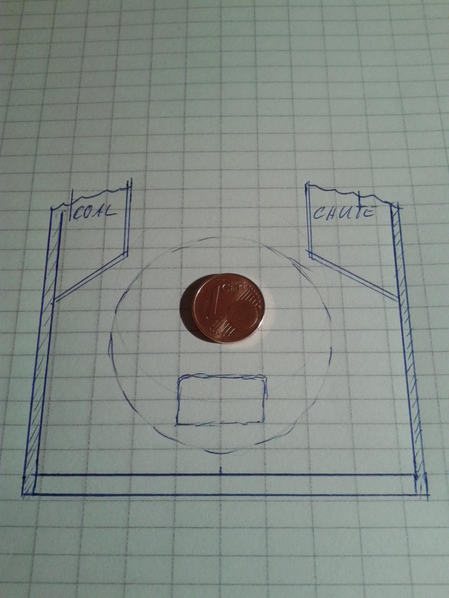
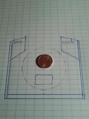
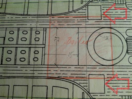
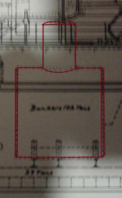
Yes defently, Ian, bad news for the stokers & teh engenieres. As my wife fall ill I had havce no time to do a plenty of work with S/S W'w'th. But I searched arround in the www and found some pictures of the rudder wich I could integrate in the plan... not a serious drawing just a scetch So I figured out that the hull's lines from bulkhead 34 - 46 are paralleel and the bullkheards are the same in outline - but the floor is maximum 1/2 inch thick on a length of 5 1/4 inch. So decided to build an "engine and boiler room box" 5 1/2 inch long and 2 inch wide with a hight of 2 1/2 inch (green is the box's floor - red is the boilter's top view). The withe square on the deckplan seem to be the bunkers top hatches - covered openings as filling ports for coal. As this is very much too wide I am able to install the coaling chute and the inner sides of the coal bunkers. Here my rough biro scetch from this afternoon - more an mnemoric device than a drawing.

-
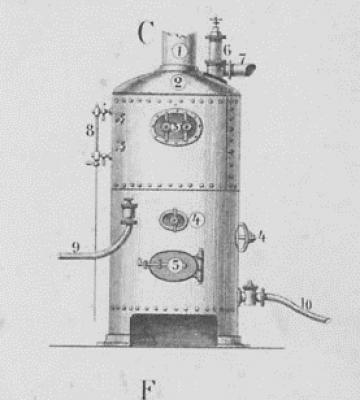
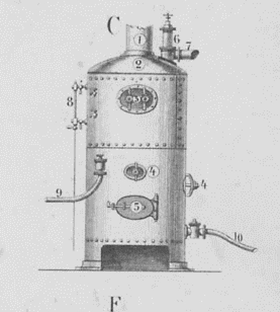
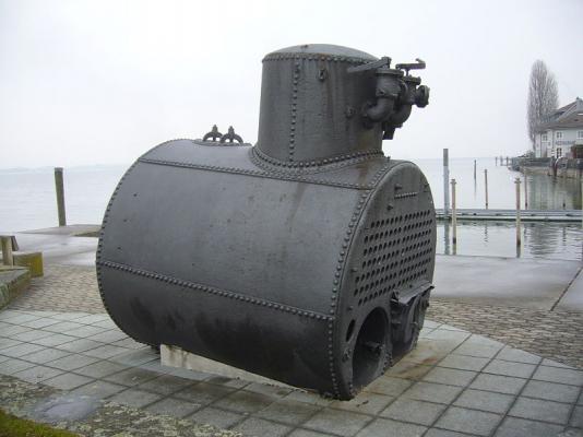
An contemporary cylindrical boiler of 1865. The Swiss "P/S Rheinfall" sunk in 1869 the boiler was raised in 1995. Two thinks are of intrest: the opening with the clamps on an threaded rod - and the big rivets on a boiler built from several plates... But much mor inmtrestin is the fact the the paddlewheeler sunk due to a boiler explosion... and the artefactum looks unharmed.
-
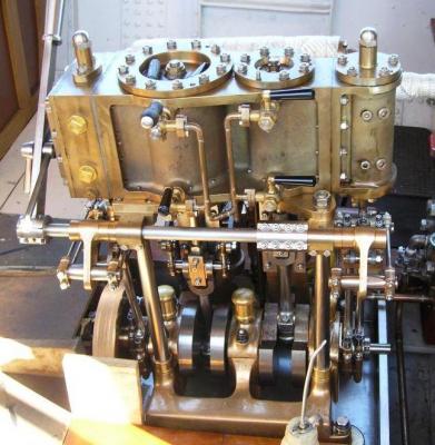
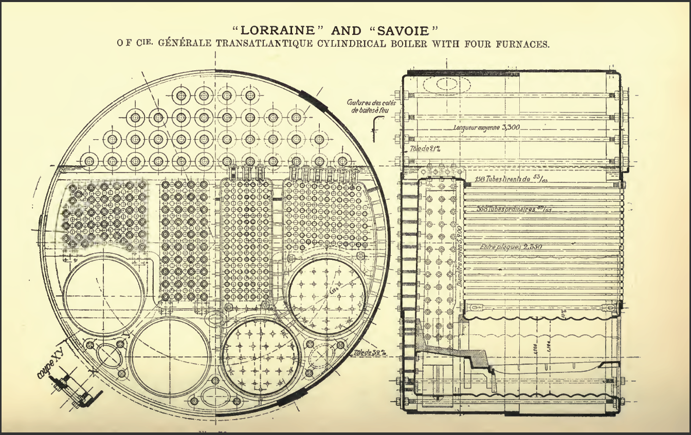
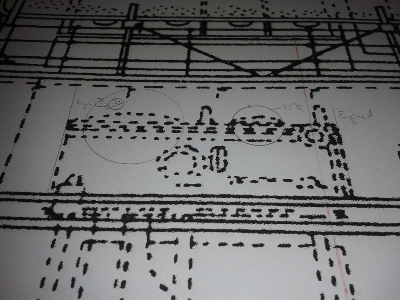
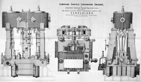
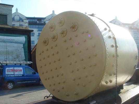
Thank you Ian, I wrote something about engines and plans in here: http://modelshipworld.com/index.php/topic/12596-ss-warkworth-an-early-steamer-not-too-big-please/?p=380854 But your lnks are very helpful - exspecially the drawing of the "S/S Singapore": I think I'll take it and try to clad it with wood to get the effect of Martin Baylis vertical Marine steam engine. The boiler's drawing is from wikipedia. As the rear side of the boiler is only to see - the number of fireplaces unintresting. An intersting detail /quite one of the bigger ones) is the steam dome on the top... wikipedia called it a " Note the steam dome, a typically German feature". And through the skylight this detail will be clearly seen. It is very big and high in the profile - mercyfully we only see the lower rivete part of it. Edit: My reconstruction of the engine top view in 1/36 - and how I constructed it from the profile plan. And I have to admit that I really love this work of figuring out such details... It's so thrilling!!! It's much more than looking to a hand full of little details and cladding them on a kit to variate the kit you're building giving it a little individuality. NOW I start to understand the fascination of this hobby and the:


-
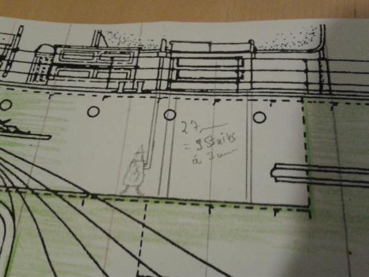
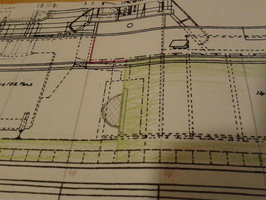
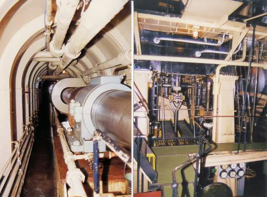
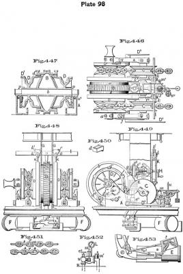
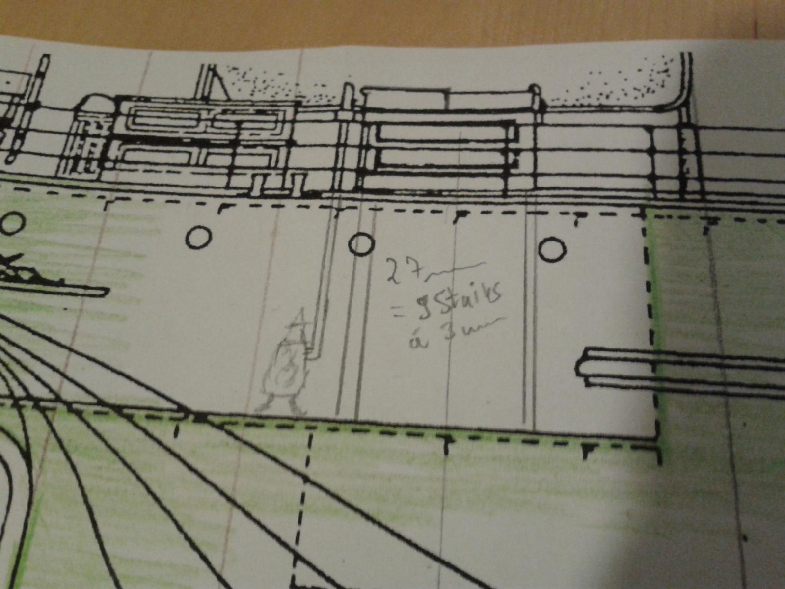
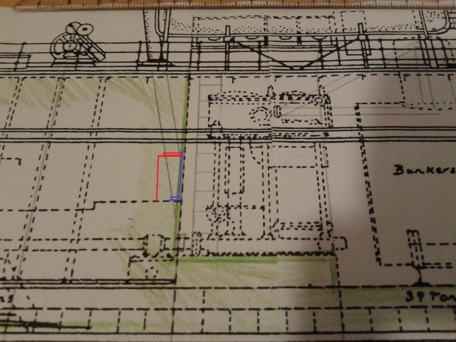
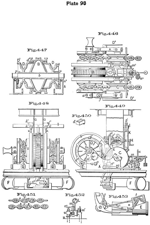
Hello friends, the reductzion of the scale started with a little overview scalked to 1/48... a new Scaleman is in work... from a figures set of the Royal Flying Corps. So this evening I worked on some inner issiues of the model. a) Luckyly the stircase is now 27mm high... and as we have to accommodate nine steps... we have to use 3mm high stair treads. As I figured out that the dunky boiler will be hidden behind the Scotch boiler and hardly anything of it will be seen - iI decided to cut it into half... k.i.s.s. = keep it short & simple c) the main mast is not shown in the profile under deck. As there is a bulkhead between engineroom and aft hold the mast must be fixed somewhere - I designed two differend affixings for the mast step... the red and the blue one. d) ...or might it be a meststep to become narrower to the end and "hitting" the roof of the "proeller shaft's tunnel" (as we call it in German) I founf this kind of ending a mast in the hull so some drawings of ironclads as far as I can remember. Which one is right - blue, red or maroon? I also found - some nice colouring of the engineroom and the prpeller shaft's tunnel. - several details for a donkey boiler - an intersting anchorwich drven by steam but without scale - a wounderful two cylinder life steam engine... but I'm looking for plans/drawings - some details of a cable tier - two pictures of the steamers after construction - and some nautic paraphernalia