HOLIDAY DONATION DRIVE - SUPPORT MSW - DO YOUR PART TO KEEP THIS GREAT FORUM GOING! (Only 13 donations so far - C'mon guys!)
×


Moony
-
Posts
82 -
Joined
-
Last visited
Content Type
Profiles
Forums
Gallery
Events
Everything posted by Moony
-
 Okay... now we are here... some poems rhyme... some poems don't rime... some are disgusting... the hull will come through a door when I tilt her by 45° to"shorten" her... but I testet it with my 1/36 printouts... and frigtheningly can never reach the floor... when I add masts and rigging... So I'll have to fish the 1/48 plan copies out... of my pile of paperrolls...
 -
Thanks a lot Bob Marvin... this was very helpful. At the monet I'm murmuring with my body plan.. due to the fact that the baseline solpes a bit to the outsuide from the centerline... So I'll have to recopy my bodyplan...and then I'll have to redraw every single bulkhead again - out of the profile... to decide where the severeal details will be positionated. The engine room is a good example: The steam-engine may a) stand on a massive pedestal as a foundation or the hole floor is in a raised position So I'll have to decide what might be more realistic... Well is this importand? Yes it is - because when I add a step in the engine room's floor I will have much more material at the bulkhead No. 52 and No. 68 both weakened by the hull form starting to get slimmer towards the after part of the hull. So Iit is a good solution to design it in this way... So every Information I get is changing a plenty of other older informations I have had - so I'm in a precess of enhancements. As I've not got a table of offsets I've choosen one of the most completed plans in the hole Serie of Waine's books I could have choosen at all. there might be more detailed linesplanes - but than I'd not have a Profile with Details, or on the other Hand I may have choosen a more detauiled profile without a good lineplan. (The only execpion will be S/S Arundel where I've found coloured pictures from her last collier voyage in the mid 70th... but she is 325 feet long... that woould give a enormoues monstrum of 2 3/4 meters long ... enough to bulit a real oceangoing RC model with a livesteam engine in her hull... able really to sail in the North Sea... an idea to dream about for the next years... even in 1/48 she will be 2,06 meters long.) So I'm going to correct the bodyplans copies and copuie them through transparent paper to get lighter lines and adding the inner structures of the hull from the profile. Dr. Murphy is so right: "Nothing is as easy as it looks... everything needs longer than you think... if anything can go wrong it will." But I figured this mistake out - and so I can avoid the fiollowing problems now - and I dont have to restore the model later when I MAY HAVE ascertained them... or being forced to burn her down in the old ways of the viking's.
-
Thanks a lot, Greg, that's very good news to me... To understand my way of building so oveercautious is that I'm struggeling with a plenty of my own inexperience, nescienceand a leck of knowledge about early coasters and steamships. It's a completly new scope to me. So every pice of a jigsaw helps completing the picture - so I can now rub out this one questionmark. I decided to giv a flat ceiling to the saloon by lowering the ceilling...
-
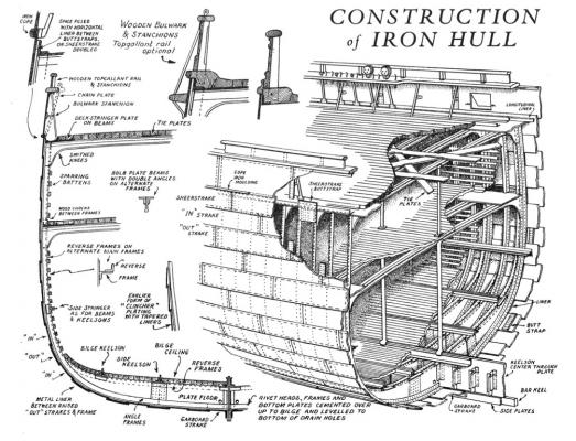
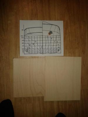
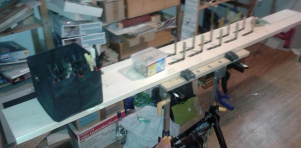
Hello, today I started to saw... to get a feeling for wood and for the room ocupied by the "Emptyness" of the saloon where I have to take off the plywood out of the bulkheads. As I fear to be wrong I cut the wood on the small saw form Proxxon without mesuing - directly from the drwaing. laying the paper and thewood on the sawing table... Here a first arrangement of my results...

-
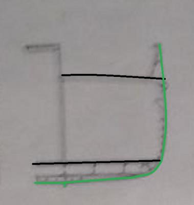
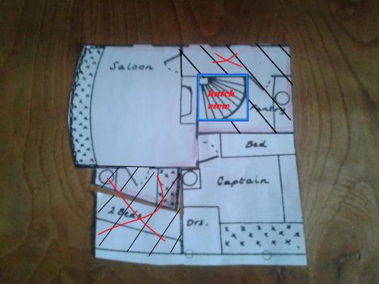
Hello good news! Jim Lead told me the "open fireplace" may only be a symbol -and so I decided to change it into a stove. This due to the factum that this is a small collier and not a greyhound of the atlantic. ... and I am able to position the stove easyly directly under the chimney/funnel. In the drawings - the cut lower decks are all horicontal - no crowning as on the main and well deck. Here a rough scetch to show what I speak about. So the ceiling is curved the floor is straight/even/smooth. Does this repeat in the officer's rooms, too?
-
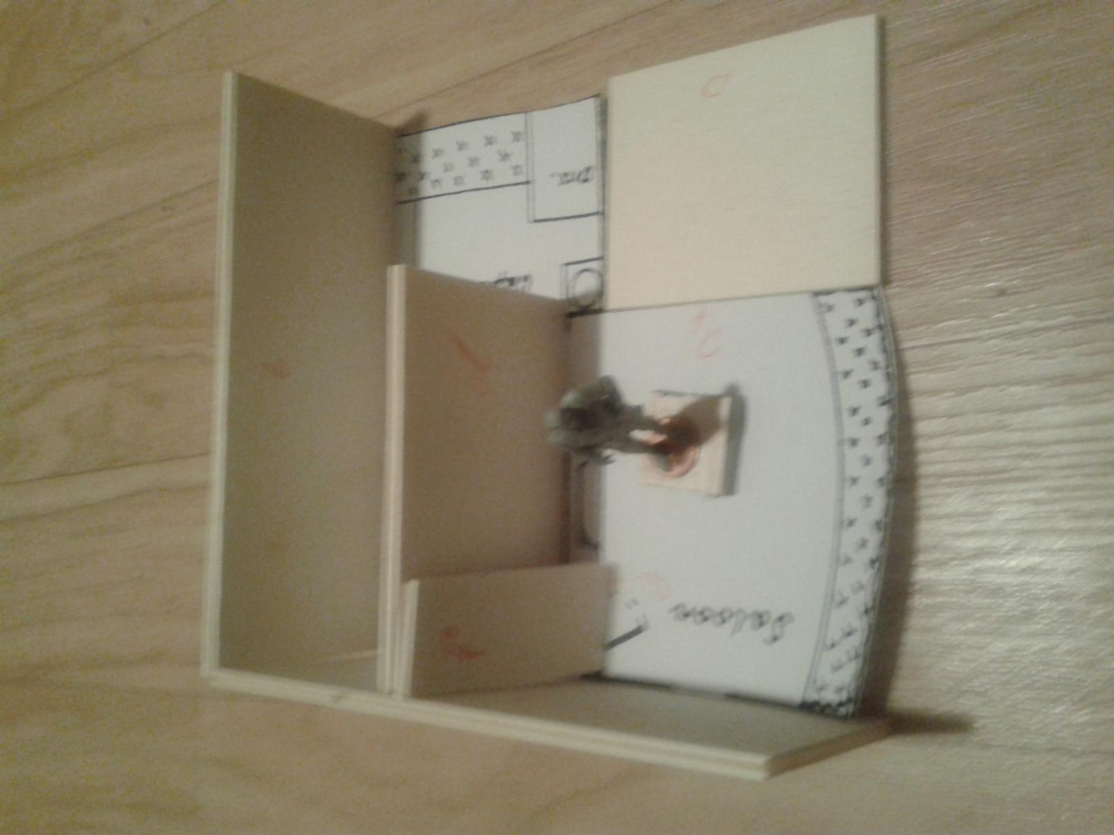
Hello here a little help for all of us with empty pockets and need for good contemporary information: https://ia802606.us.archive.org/22/items/shipbuildinginir00reed/shipbuildinginir00reed_bw.pdf
-
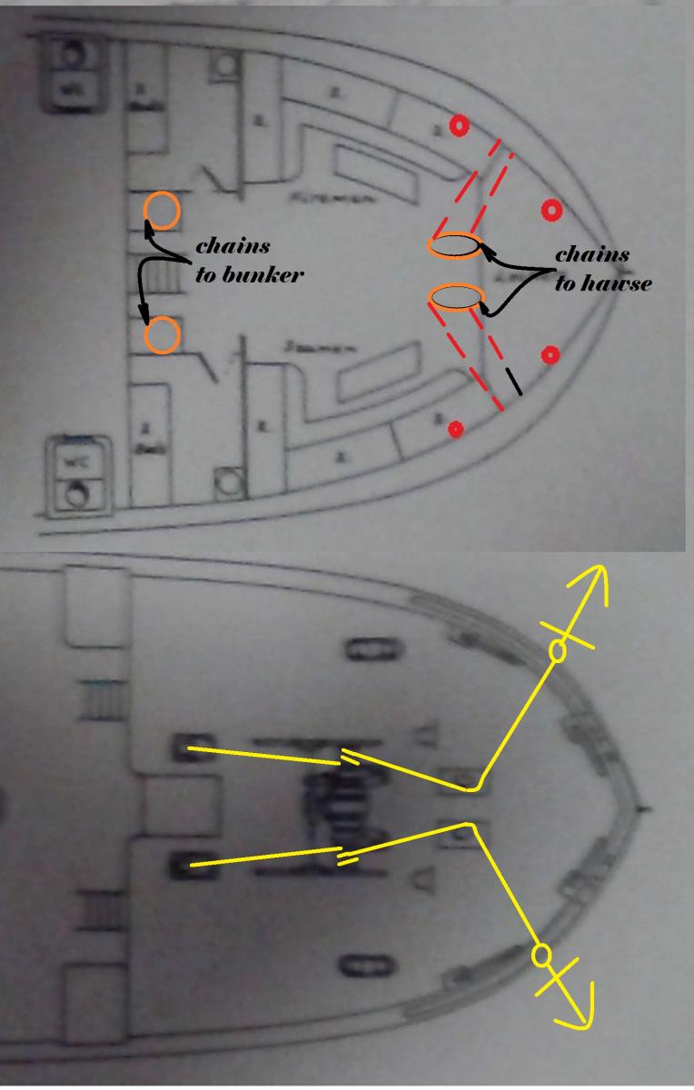
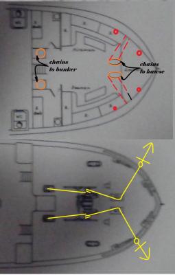
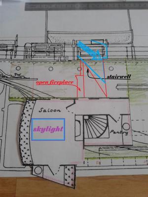
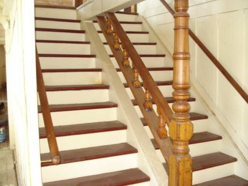
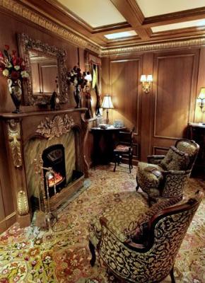
Hy druxey, so eveybody should avoid claping at all ... Okay the anchor cranes riveted me - I'll make a proper multiview orthographic projection on tracing paper to get rid of these bunch of doubts & questrions. The desing of the modes is changed now. The next step is the modelmodel of the saloon and the forecastel: The question to the inner structure of the forecastel is the folowering one: What a bout the anchorchains way to the chain's bunker under the sea- & fireman's quater? The topviel shows a chainstopper to uns and an opening foreward where the chain seems to run trough down to the anchor's hawse. But if there were no hawes in the hull's side - if the anchors were stored on the forecastel's sides - as before the stockless anchor? But as "anchor" in The New Encyclopædia Britannica. Chicago:Encyclopædia Britannica Inc., 15th edn., 1992, Vol. 1, pp. 377-8 tells us it was invented in 1821. In teh profile drawing there is no anchor at all... What do the specialists say... anchor hawes in the hull's sides for a stockless anchor or not in 1873/74? The question is - what shall I show if the stariwell's door is open? So I'll have to build a cardboard model of the forecastle to get a "feeling for the inner structures". The saloon is a bit more complicated because I'd like to show a lot of it through the open skylight. And I want to show the captain's cabin, too. The stairs seem to go down very fast and the stairs plunge. You can look down though the open hatch so I need to built the detail very meticulous. The Innerside of the stair well will be made from bright wood - also the saloon needs to be pale. There is an open fireplace in the saloon the problems witzh the smoke's disposal you can read here: http://modelshipworld.com/index.php/topic/12596-ss-warkworth-an-early-steamer-not-too-big-please/?p=384966 This is the prelude to the "modelmodel" - here we're dealing with building. I searched around and found some pictures of staircases and openfireplaces - here the best I could get.
-
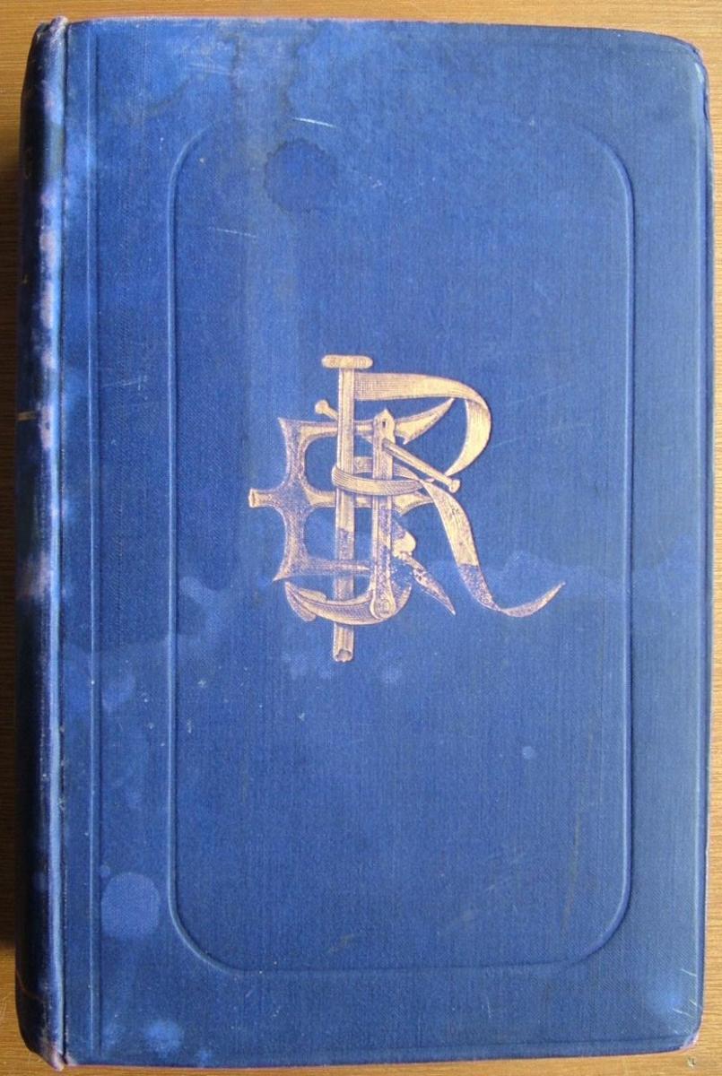
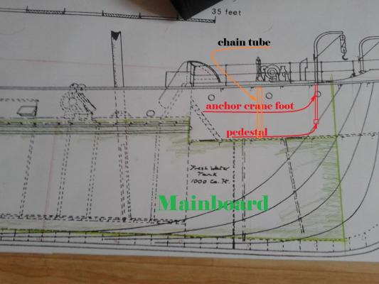
Hello. I worked today ion the inner structures of S/S Warkworth and in the both "Waines" Luckyly I found in "The colloier fleets" a coloured picture of S/S Broomhill owned by the same company - so I've got an idea of the couloring. What I've not got is the company's house flag. I also found an interesting picture of S/S Lucania - showing the angle irons in their often appearence. Due to the fact that beside the engines room the coal bunkers are placed I'm a lucky guy. Why? Because 1st the walls are straight 2nd tI don't have to show the bent irons of the frames and the inner side of the outside plating. Here a top view of an engine showing the imense number of pipes. All this can be seen through the open skylights. Here the engine is placed aft, so the coal bunkers is more a cross bunker as in S/S Warkworth. Here the situation in the plan of S/S Warkworth - it looking a lot simpler: To pick oput a 2nd point I've learned today I'm goint to show an interesting detail to you: The anchorcranes: The cranes for the anchors on the forecastledeck is a little detail I looked at today - sitting as an unwitting participant in a low-threshold New Years charity concert. So I had a plenty of time to think about anchorcranes in general and the ones I'll build in particular. Expecialy by not listening to third class singers beggaring my time with musical and operatta... So I was affraid of blueing my foremoon for the family. But I sat smiling between phrenetic people clapping their hands semi-rhytmicaly while the orchestra tries to play the famous Strauss's Radetzky march... So I cut everytig around off and managed to safe my time by escaping in the inner garden of my mind... thinking about a detail in the S/S Warkworth plan: It looks quite easy - but would it strong enought to take the weight of the ancre? Some hours before the concert I leafed through the book and I found the answer to this question: The ancorcranes foundation is going through the f'c'stldeck - it's base placed on the balasttank's top... but noting is shown in the drawing of S/S W'w'th... it just schow's a mixture of the profile outline and waterline's drawing... bad luck to me. Here a little "photomonatge" of W'w'th showing the position of the hyotothetical prolonguationpoints of the ancrecranes: But the problem is in the position of the foundations... Do the pierce throught the ship''s side??? To figure this out I've to make a drawing of the f'c'st'l deck - by integration of the former lines to carve out if I need a plinth at the hulls inner side. These were the cogitations I dealt with today... nothing to see from on the hull at the moment... but I think it is unavoidable when I want to open the hatches and give a look in the cpmpanionways. You're right to say nothing can be seen - the lowerpart of the cranes are eventually running through the fire- and seamens beds!!! Or behind a wooden cladding... why do I burden my brain with those trubbles? There are no rails for the anchor chains - can this be right - or am I spoilt by the Navy Yard's battleship f'r'c'stl's accourtrement? The next problem is with the rudders chain - where is it joining the rudder's quaterwheel and the two helmsman's wheels!
-
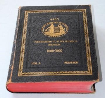
Oh you are rigt, John. And to make matters worse S/S Warkworth built from iron - not from steel. So all the knowledge we finde is useless. I'll have to "digg deeper" to find the right normenclatur for the thicknesses and measurement of rivets and plates, The dimensions of angeliron, the measurements of brachings and so on. To get the same solidity parts had to have bigger dimensions - this was why steel swiftly replaced iron. Due to the fact that shipbuilding from iron was a British business I'll have to look in the volumes of engeneering magazins to find the information I need. Do you think it might be helpful to ask for information about the applied 1873/74 classification rules at Llody's Register in London? That's what I like... the thrill of research - finding out newish information... to be honest I just have to rediscover them. But the first Llody's Register dated from 1899 - 1900... So the question is where to find these particular datasheets?
-
Yes the is starting to beat with her wings... what I hope is that the model will assemble from the parts as logical as it looks like everywhere here. The ship is the resultant of the parts I put together... but not Tamiya is responsible for the fitting of the parts - it's me!. The challange is to get them so fine and realistic as possibe. The close "affinity" of the scales 1/40 (or 1:39,78 to be Pooterish) makes it possible to use some of the 1/35 items like the tiny Meng or CMK screwsets. ... but with a plenty of unanswered questions... For example the pre-Pimsoll Load Line Mark is with an L and R letter but before 1876 there is a diamond not a circle. The measurement of the iron-ship loading lines is a complete terra incognita for me - so I'll try not to mess around with the load line marks. What I'm interested in iss the changing between the "big work" with the 6 mm plywood on the one hand (I never had without building a scratcher for cats and installing a truss for a child's swing with joisthanger five years ago. I fogot the construction of the high sleeper several years ago with a wrongly adjusted bubble level... So my tooling partly is too rough - on the other hand I've got some very fine files, tiny cutters and an extra hand with magnifier but the tooling between... there an abyss gives a yawn
-
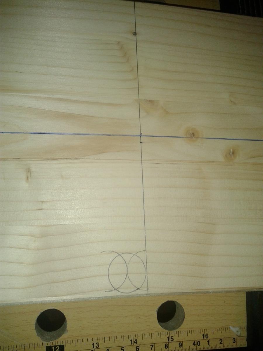
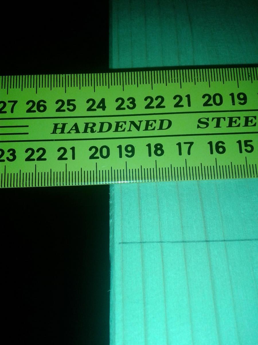
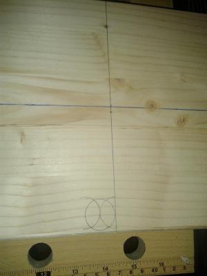
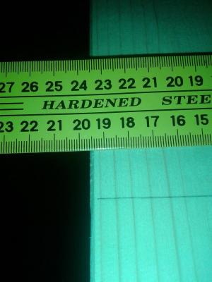
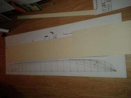
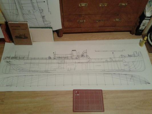
Hy Ian, she is an intresting ship - I'll have to reconstruct a plenty of details still not in the plan at the monemt. Oy yes - she'll be a bit about 1600mm long - she is a tall lady Here the Centerline the Mainfames placement and todays pi**-take... you pay for 200 mm and what you get is 195 Next station: a) cutting out the bulkhead copies. Transfer the bulkheadlines faced to the mainframe with a pairr of compasses.
-
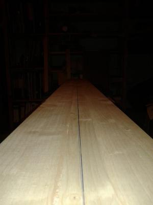
Hello friends of the S/S Warkworth, now I made my way back from the DIYshop... everything wraped in dustbinliner to protect the plain wood from the ugly snowraining weather outside. I bought a 2000 * 200 * 28 mm plain board as yard board from pline. 300 * 250 mm and 10'' * 8'' plywood boards beechen. 250 * 600 mm and 200 * 600 mm for the centrl board plywood pine. Now I can start to put mindcraft ine the cuts that'll be done. I decided to use two seperate parts for the midships board due to the fact that the longer plywood boards looked like the waves of the Sea of Galilee. Now I'm able to start...
- 43 replies
-
- 11
-

-
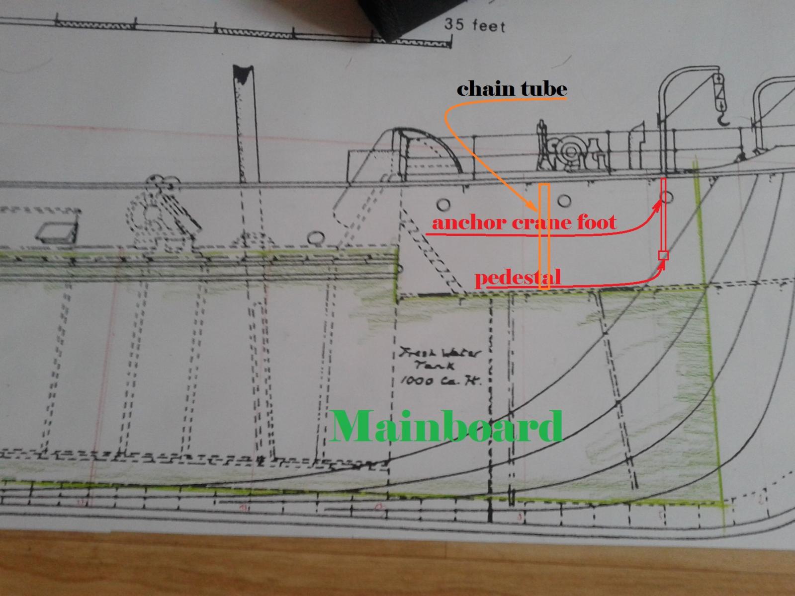
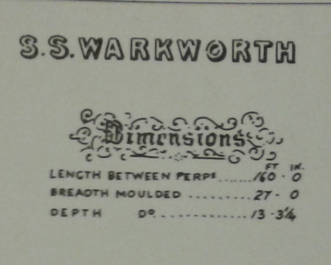
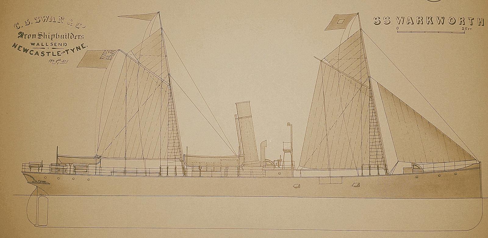
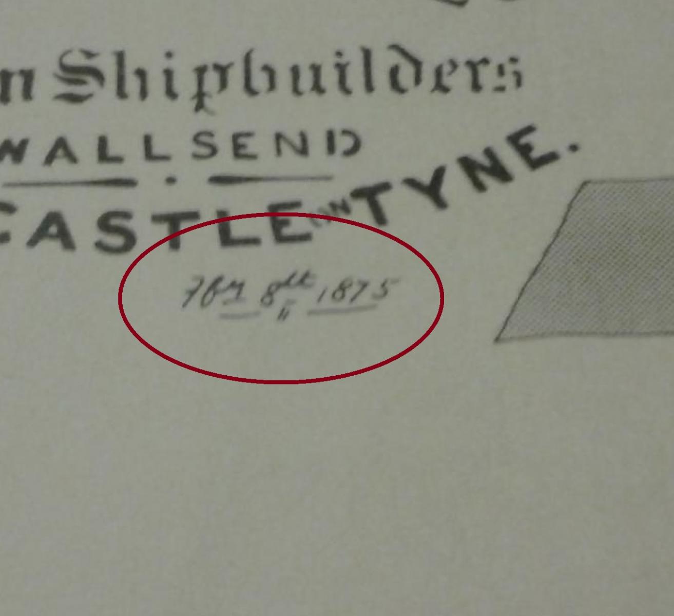
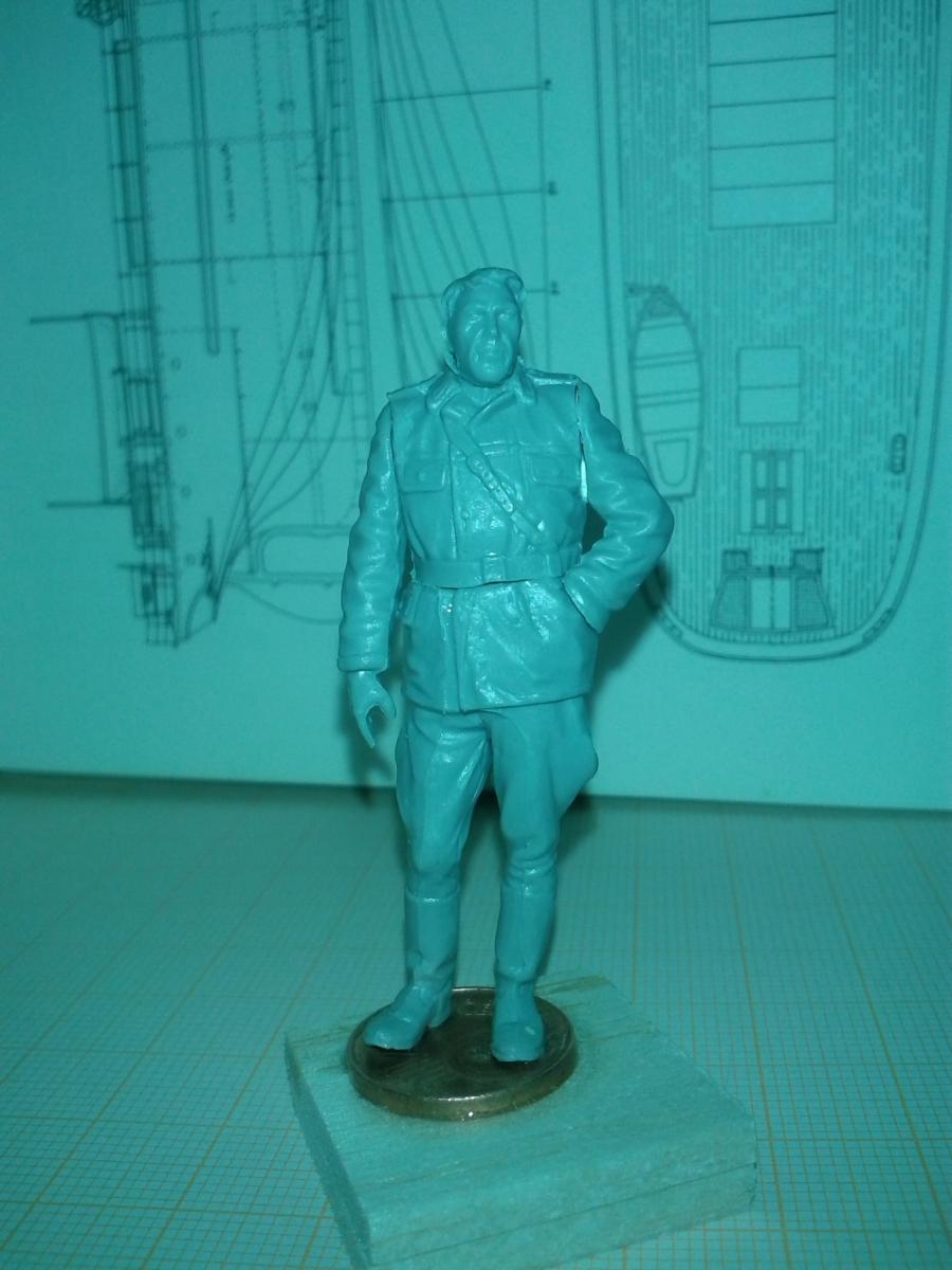
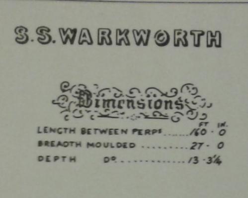
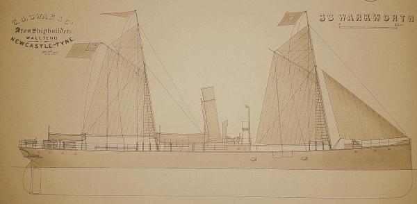
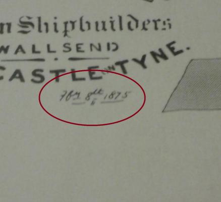
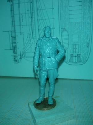
Hello wood-, iron- and steelworms! The very first thing I've to admit is the scale is nominally 1/36 - but due to an enlargment fault it is only 1/40. So I said to myself "Damed 4 dots beside the lne... it could have been the drying of the paper or the wrapage in the big copy machine... so I decided to take the plans as they are - and do the start with them. I've got a thread about the plans here: http://modelshipworld.com/index.php/topic/12596-ss-warkworth-an-early-steamer-not-too-big-please/ andall the planing facts will be placed there. The S/S Warkworth was built in 1874 in Newcastel up on Tyne on the shipyard of C.S.Swan & Co, out of iron. I'didn't find a prpper date of launch only this date on the (usualy coloured) sideview of S/S Warkworth. This can mean she was launched on the 8th II. 1875 or the drawing is dated to this day. Does anybody know something about dating traditions in the shipyards on Tyne? The ship was ordered by H.Andrews who was connected with Broomhill Coal Co. for the coal transport and built in a progressiv design. It is now known that if the angle of the water flowing to the line of the keel after is exceeding about 18°, the flow of water toward the propeller is liable to be turbulent in creasing drag. Due to this the lines were altered compared to former designs. She has got a complete forecastledeck - til the bridge the deck is iron not any longer wooden. To store the new cylindrical Scotch boilers the deck of the boilerroom had to be raisen - the enginerooms hight had to be extended too - due to standing hammer steammachine with a high and low pressure cylider. This kind of construction was basically used for the next three quarters of a century - till the steam coasters started to disappeare in the mid 1950s. The captain was no longer near the rudder as used fore the last 3000 years - hhis place went to a flying bridge infront of the funnel - raised on a little platform called "Flying Bride". To seperate it from the "real" bridge connecting the two side wheel boxex earlier. This interestin light construction gave a good overview to the Officer giving orders to the helmsman behind and below of him at the main steering wheel. S/S Warkworth was built to transport coal - so she had two big cargo spaces of 14,15o and 13,ooo cubicfeet - for ther own coal consumption she had a 102 ts coal bunker. She works in coal trffic on the north-east coast of Great Britain and measured imperial. and registerd with: 160.8 x 27.1 x 12.9 - at 555 grosstons and 334 nettotons. driven by a 70 hp machine on a single propeller. All the data are from Charles V. Waine's books Steam Coaster and Short Sea Traders (2nd Edition 1980) The Collier Fleets (1st Edition 1990) As you can see from the pictures there are not too much details that overcome to us. I couldnt find anything about the propeller - with out the fact that it was a single one... but does he have five, four or three blades? So I'll start with the building board and the backbone next week. The construction of the bulkheads will be shown in the article about scetches, plans and drawings. As all the pre-work is done there and the "output" is shown here to you. The real building progress will be shown here - to give you an Idea of the size I built a little figure for you - standing on a €-cent coin and based on a square-inch he is to scale: MrSquare-Inch EDIT 12/Feb/2016: Due to my flat's groundplan I've to reduce the scale down to 1/4'' to the foot - 1:48... Hope you like him.
-
Hello "crew"! Dealing with early colliers/coasters I collidated with the question of the thickness of iron (NOT steel) plates - revited on the formers to form the hull. As I'm building in 1/36 I'm forced to give them the very exact and right dimensions... this is the source of my outlandish question. The surviving coasters (S/S Robin, S/S VIC 32, S/S John Oxley or S/S Sir Walter Scott) are all steel hulled - so these information is not very helpfull to me. About the sailing ship iron hull building is said for the 1860s: "The earliest iron hull plates were very small by today's standards, no more than 6 ft by 2 ft 6 in. by approximately 3/4 to 7/8 in. thick, and with about 18 in. frame spacing." Do you know anything about the newcastle iron plates measurements used for steamers in the first half of the 70th? Here a drawing from mcjazz.f2s.com :