HOLIDAY DONATION DRIVE - SUPPORT MSW - DO YOUR PART TO KEEP THIS GREAT FORUM GOING! (Only 64 donations so far out of 49,000 members - C'mon guys!)
×


George-JK
-
Posts
57 -
Joined
-
Last visited
Content Type
Profiles
Forums
Gallery
Events
Everything posted by George-JK
-
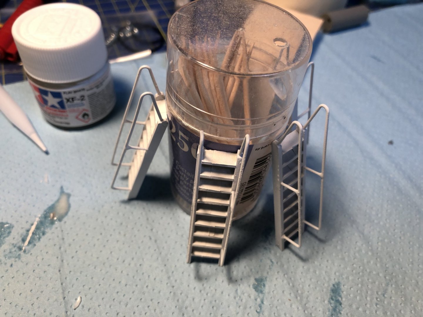
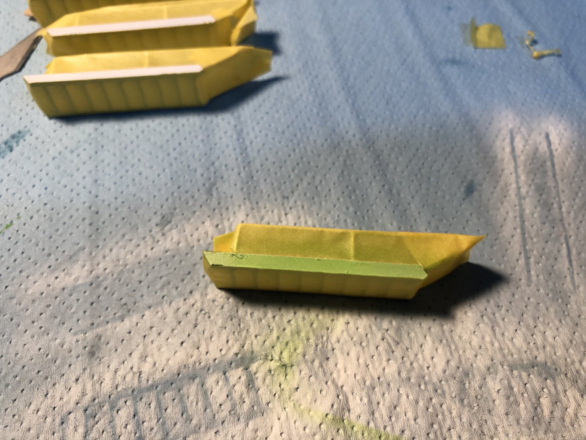
Hey Peter, As you say, to me it looked a bit strange, that the top ladders are painted orange and the bottom ones should stay white, or even orange. It just din't fit to my impression of the model. And since the collour scheme of the model is already looking like a tropical bird, why not add a little extra touch of green to it... Yeah the water tightness test is scheduled for today so we will see... Cheers George
- 90 replies
-
- 1
-

-
- fairmount alpine
- billing boats
- (and 1 more)
-
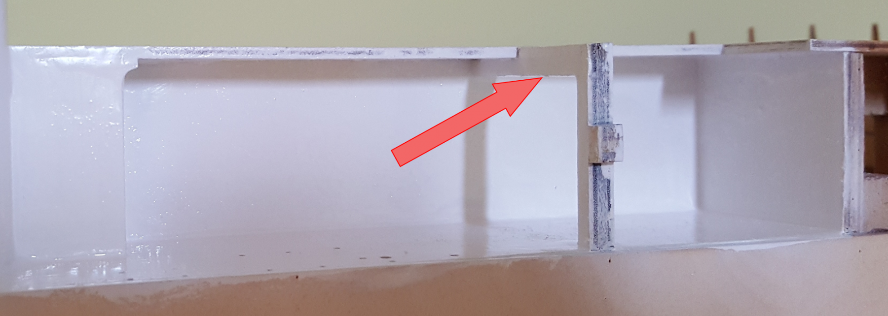
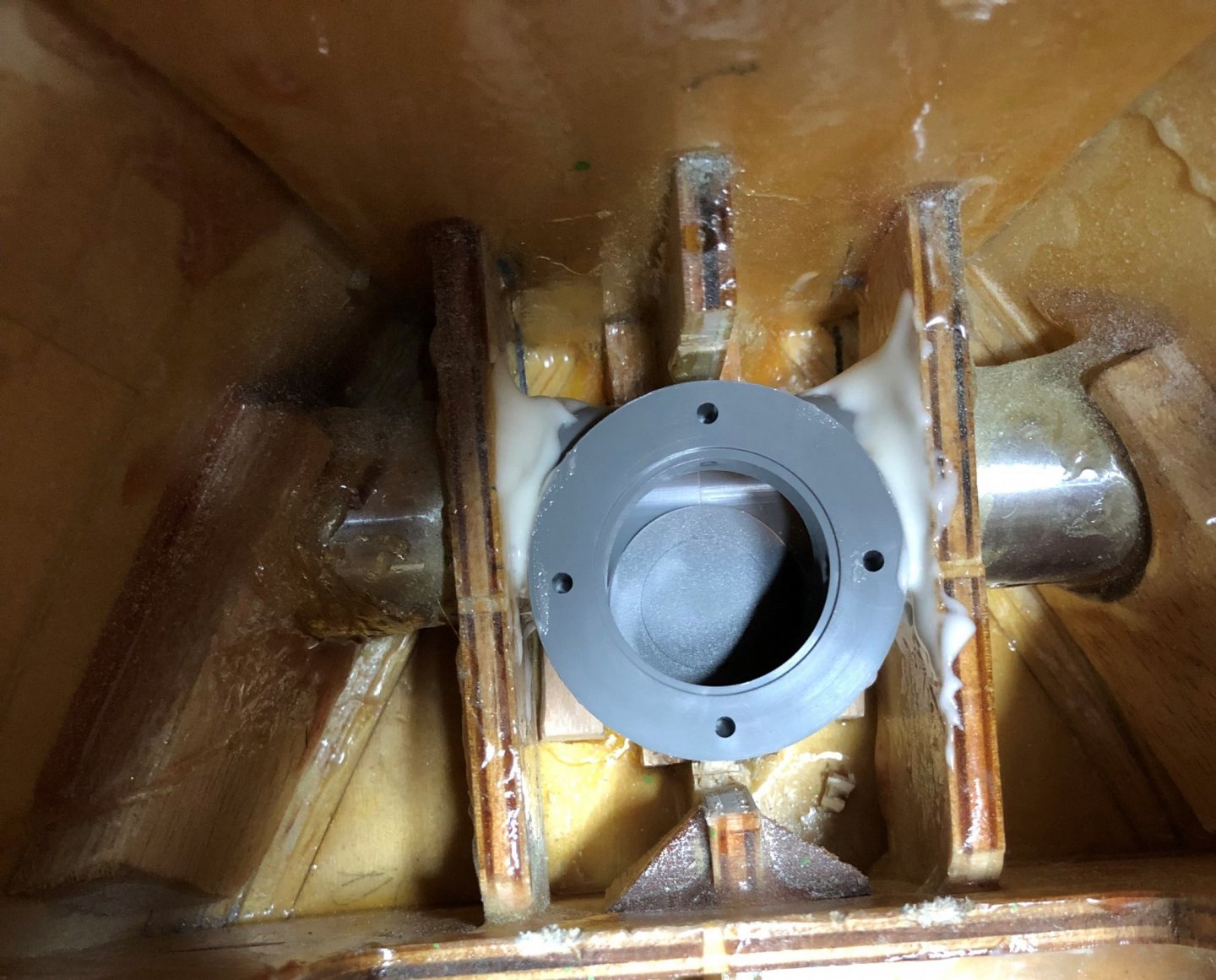
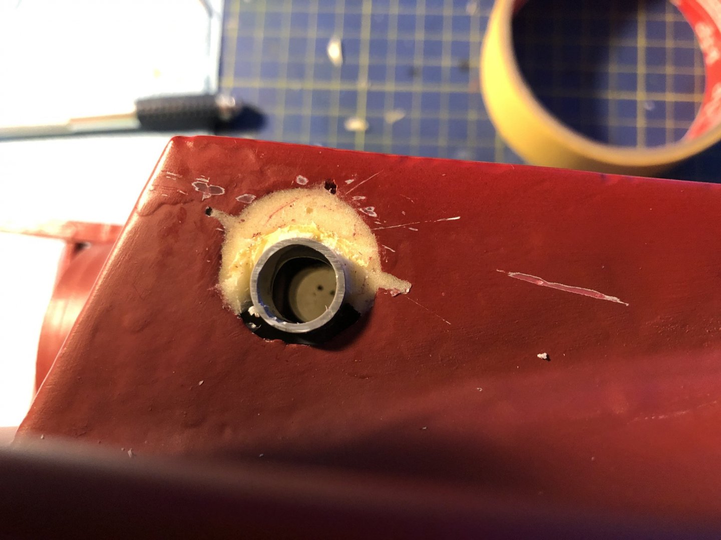
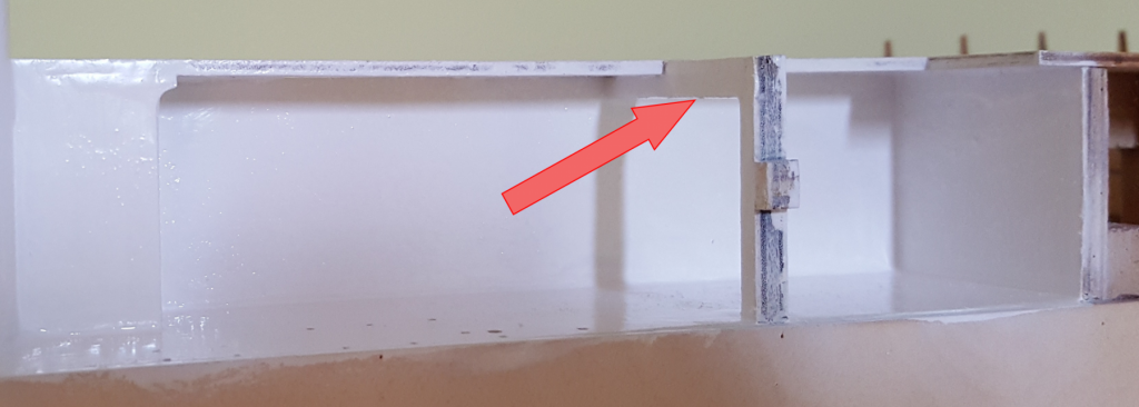
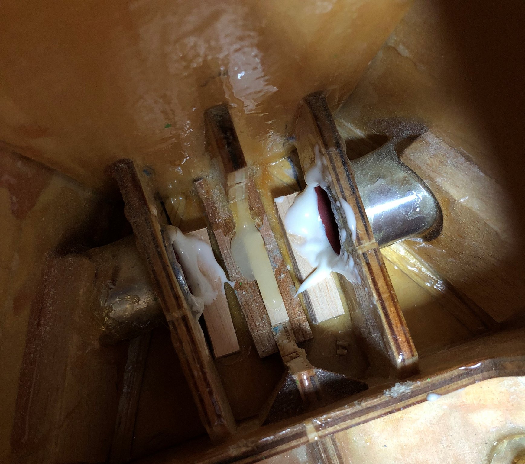
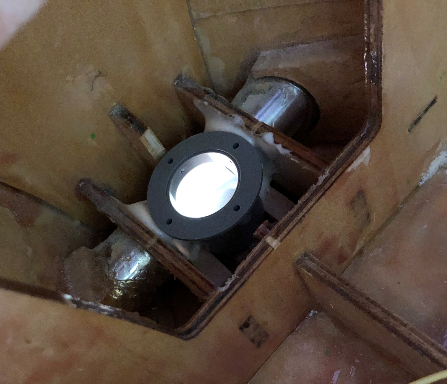
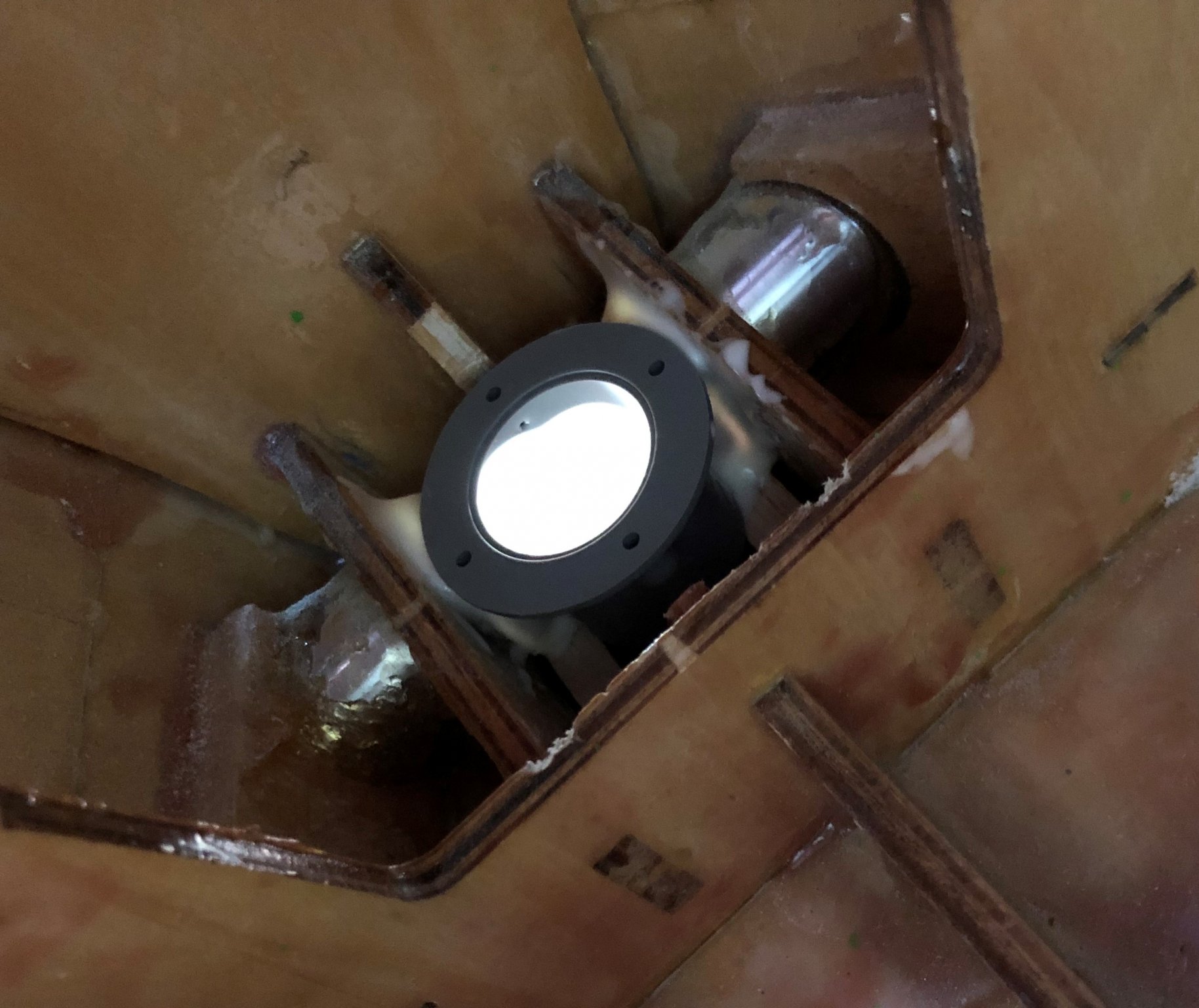
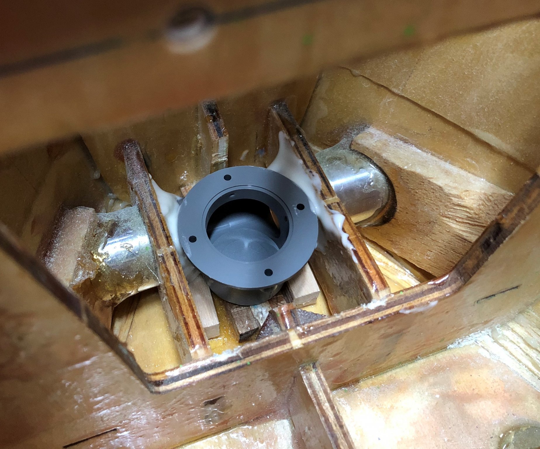
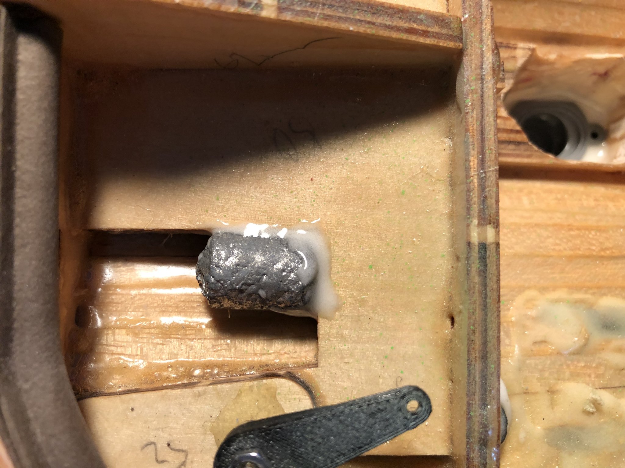
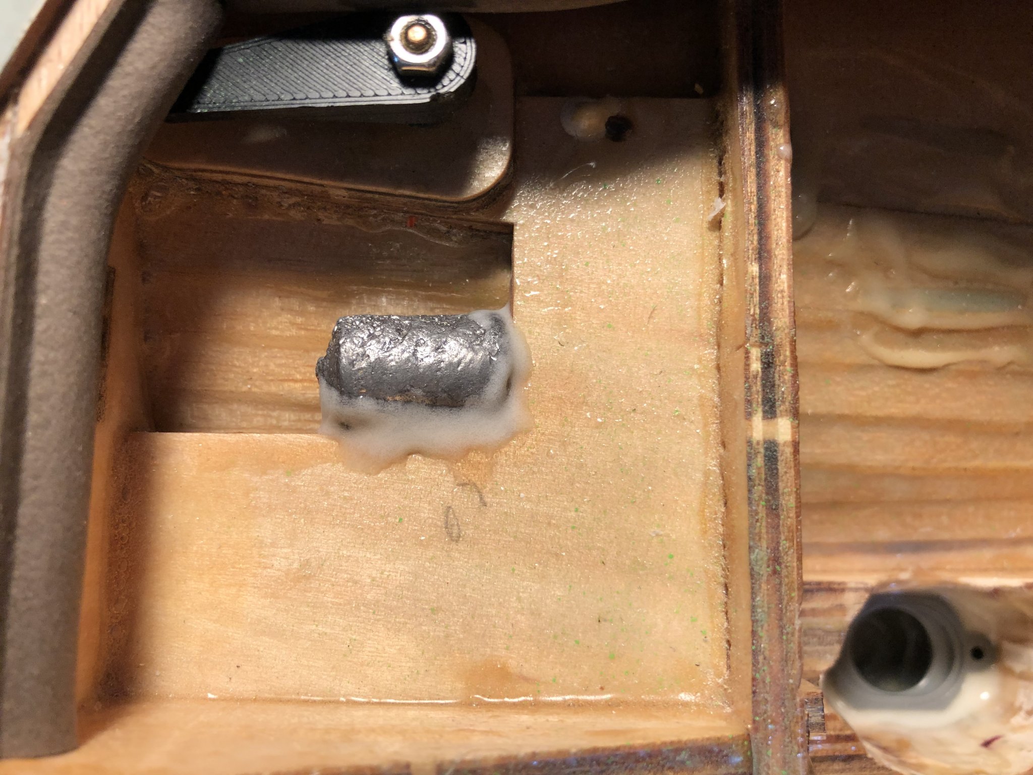
Hello All, @Seamanpeter thank you for the description of the ladder problem, I was not sure if they should be the same distance, or if the distance is somehow dependent on something. I will do them with the same distance as the ladders included in the kit have. Yes it is the same phone casing 😄 well the phone is still good... So yesterday I finished gluing the stern thruster and started gluing in the bow thruster. In the stern thruster glue, there are some voids left, these will be filled after the initial sanding of the excess material, as some of then will hopefully vanish. The gluing of the bow thruster consisted of mixing the 90min epoxy with the air balloon filler, until it had a non dripping viscosity. Then I just smeared the glue on the ends of the original bow thruster channels and on the thruster body itself and assembled. The rest was then checking if there are any holes, and filling them up. The first picture shows the hull section with applied glue. The second picture shows the inserted new thruster body, with filled top parts of the joints. A different look on the new thruster installed, and checking for glue thickness/ voids. For this I used a phone flashlight (any strong lightsource can be used) shone through the channel entrances, and by the varying intensities of the scattered light visible in the glue joints, one can tell quite accurately the relative thicknesses of the glue joint sections. As I was waiting for the glue to cure I went and finished painting of the 4 ladders used on the hull. I went and painted the sides green, I wasn't certain what collour they were suposed to be, but as the ladders of the superstructure have orange sides, I though that these should follow the trend and have the sides painted green. Cheers George


- 90 replies
-
- 3
-
-
- fairmount alpine
- billing boats
- (and 1 more)
-
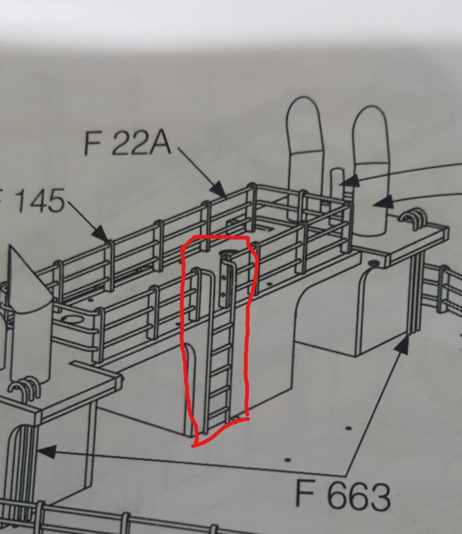
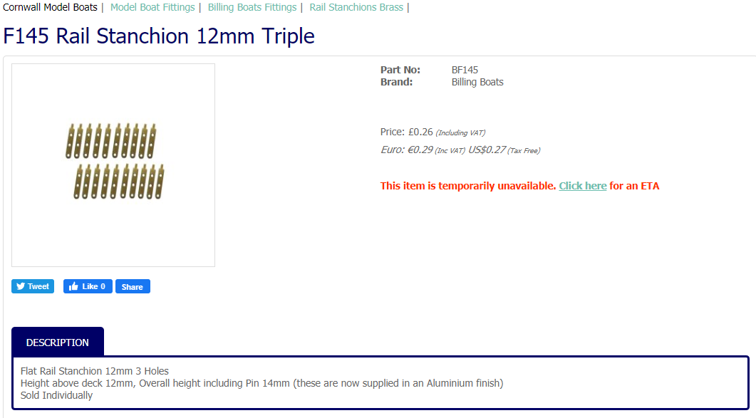
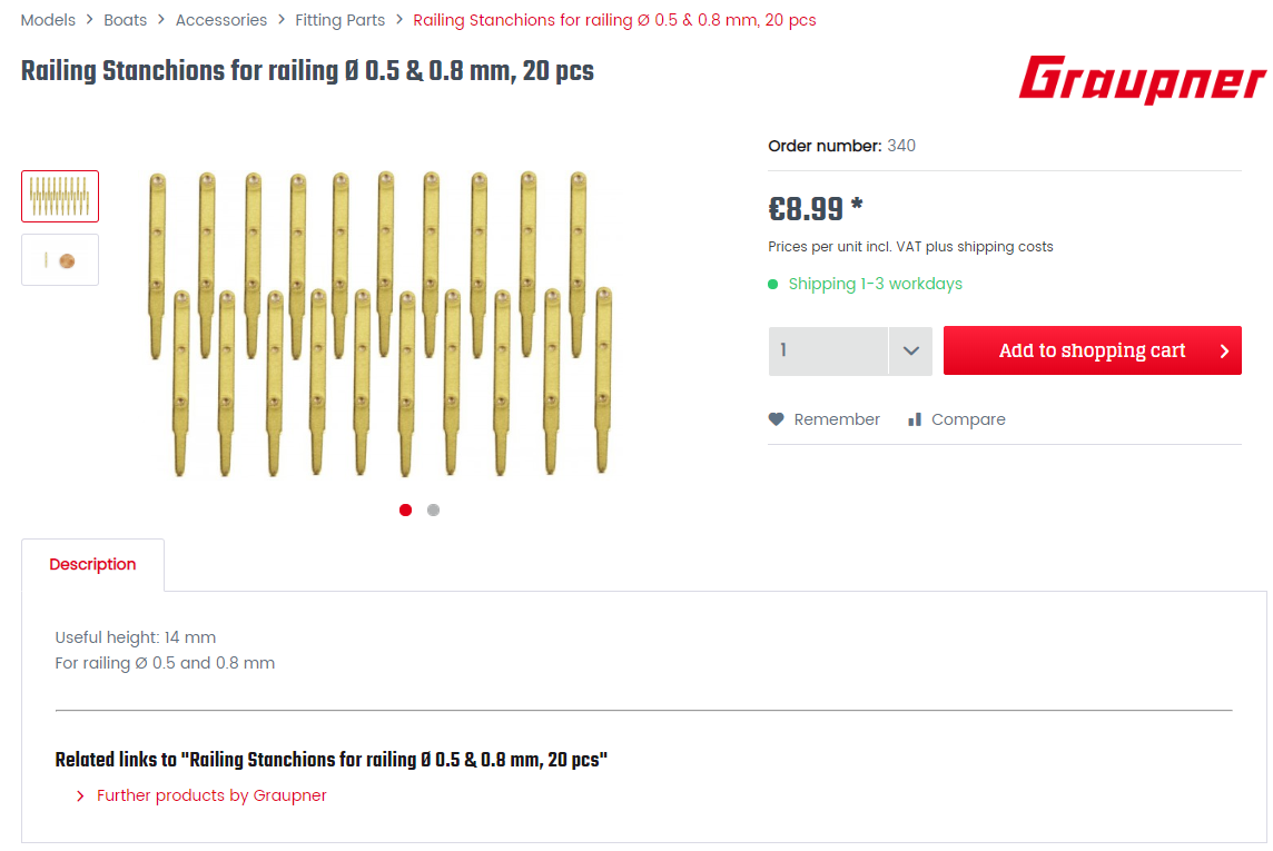
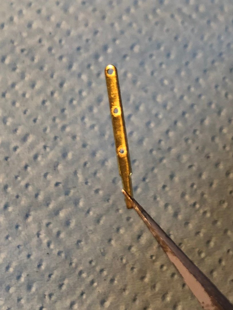
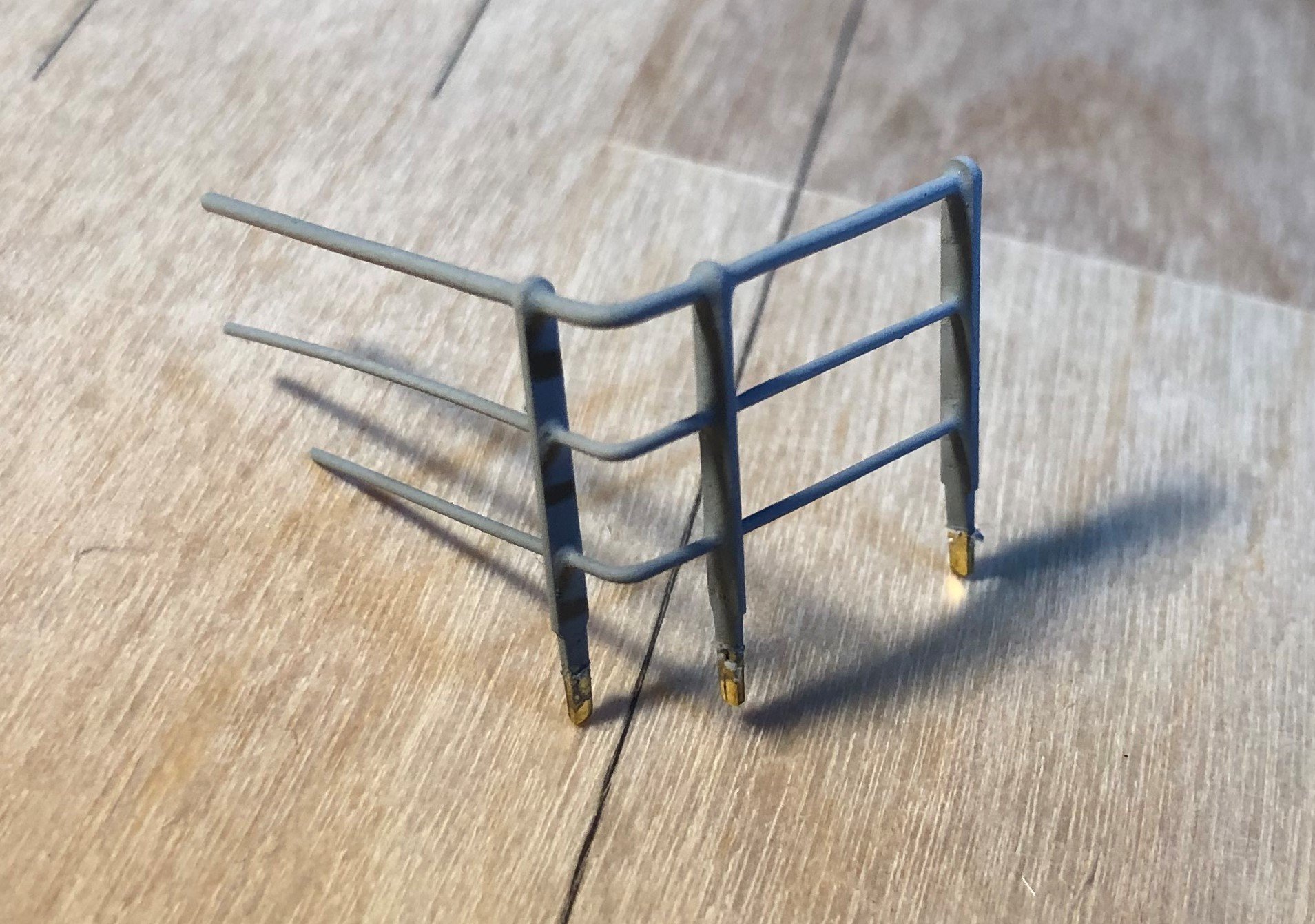
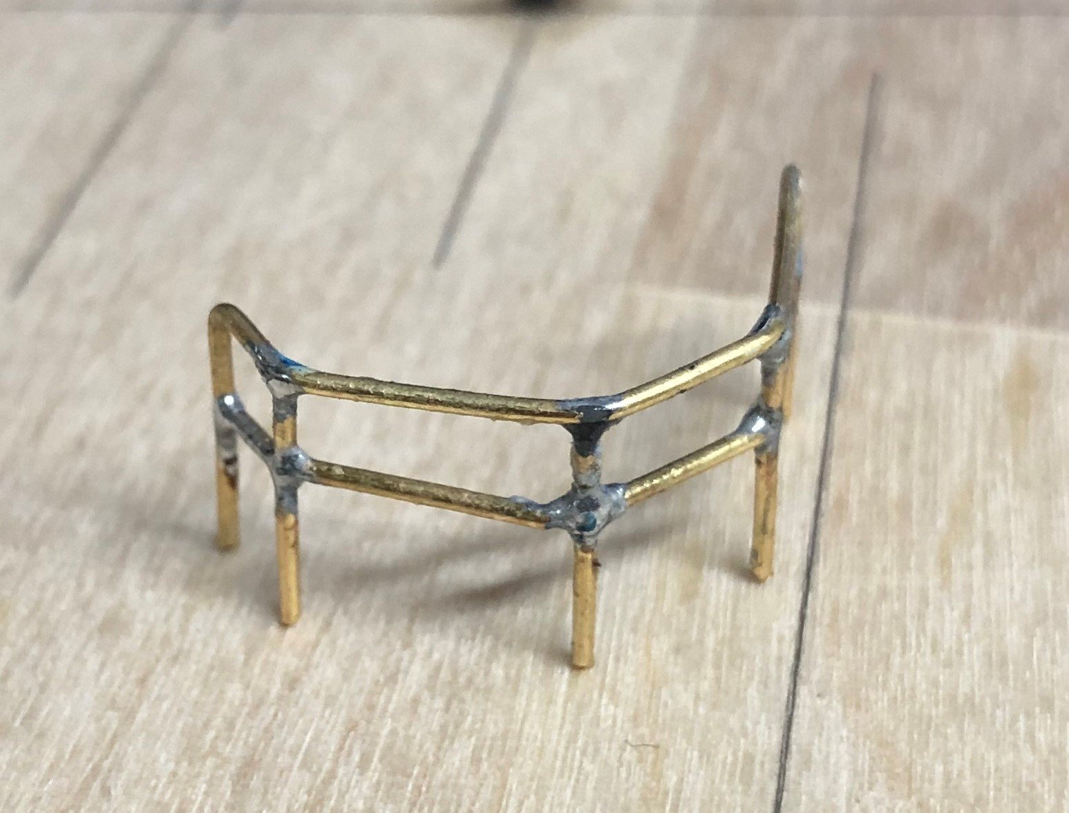
Hey Peter, Thank you for the insight on how it actually is on a real vessel. Honestly sometimes I tend to over-complicate the things I am trying to say. I should have written: That after searching the internet for a suitable replacement made of brass, most important factor, I found these rail stanchions from Graupner, which are 2mm higher, that the original ones, but these 2mm are, at least to me, lost in the overall model size. And one additional advantage of these stanchions is, they have the two different hole sizes bored in, which as I seen on the pictures of real this boat, and from my travels with ferries, to be the case. The top rail is bigger, than the lower ones... Regarding why I don't use the 3D printer for this. Firstly the end product, being so thin would be very fragile, and it simply would look bad. And secondly, I quite enjoy the soldering of the rails, and they are in the end quite bendy- sturdy so to speak. And lastly, I would like to use your experience, to ask you a question regarding this one ladder: I would like to know, what would you suggest for the spacing between the individual steps, and also what should be the optimal spacing of the first step of the deck? Thank you Cheers George
- 90 replies
-
- 2
-
-
- fairmount alpine
- billing boats
- (and 1 more)
-
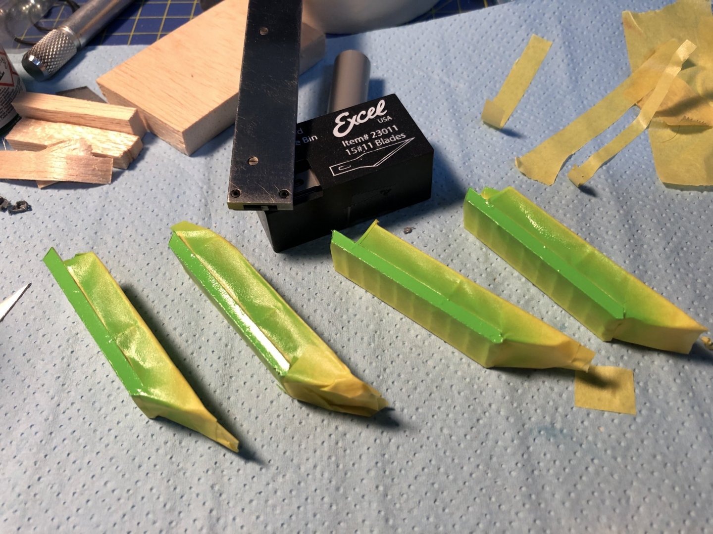
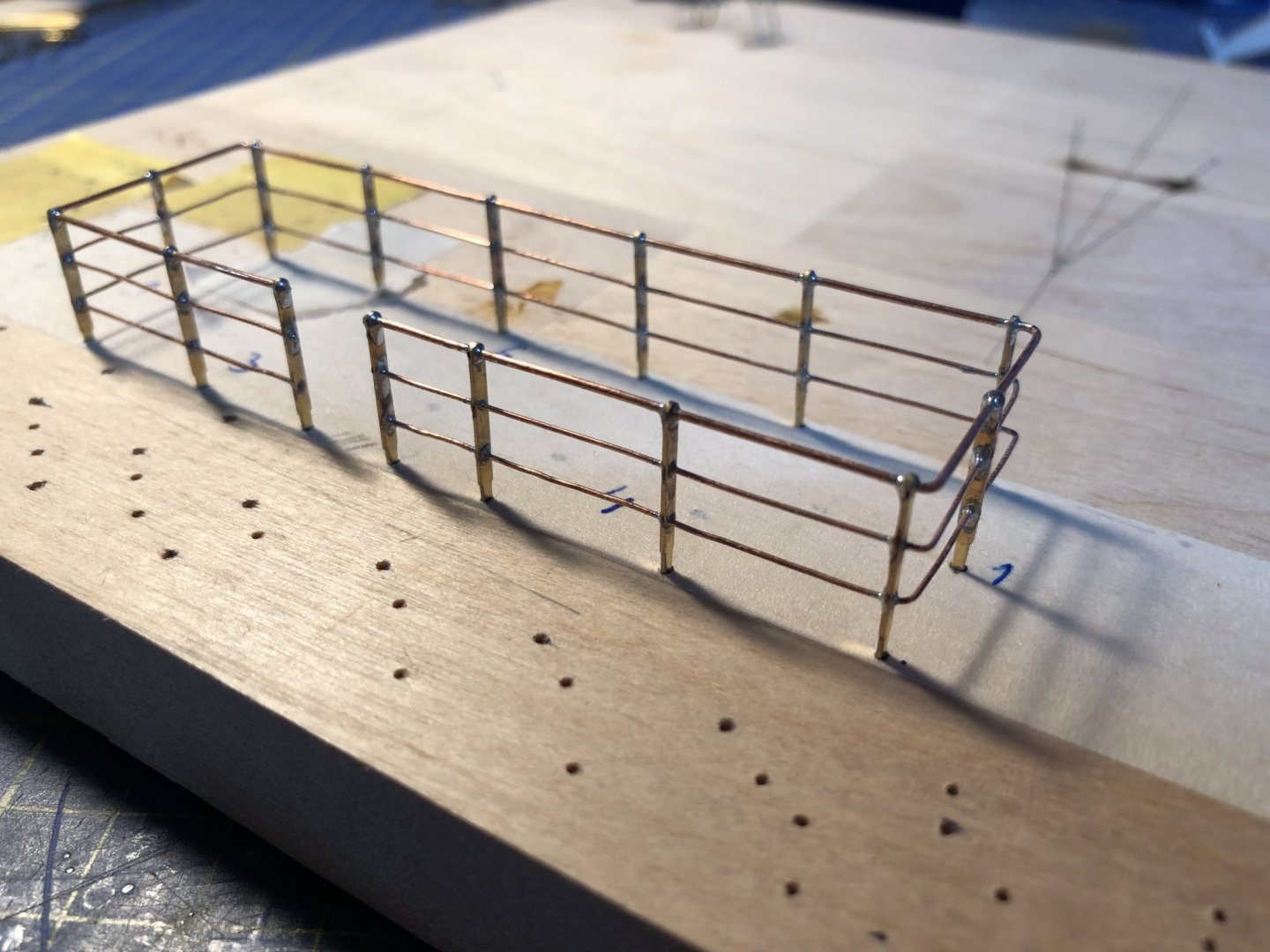
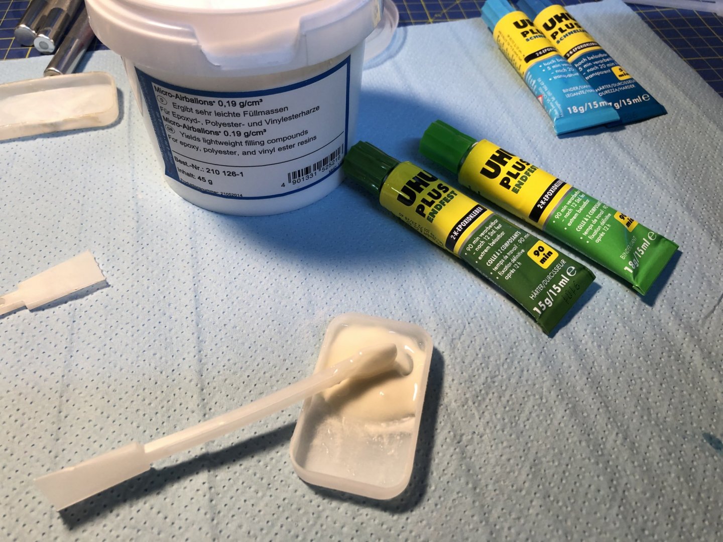
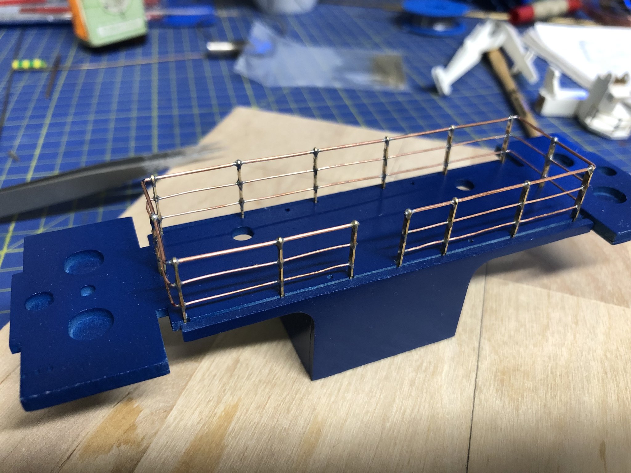
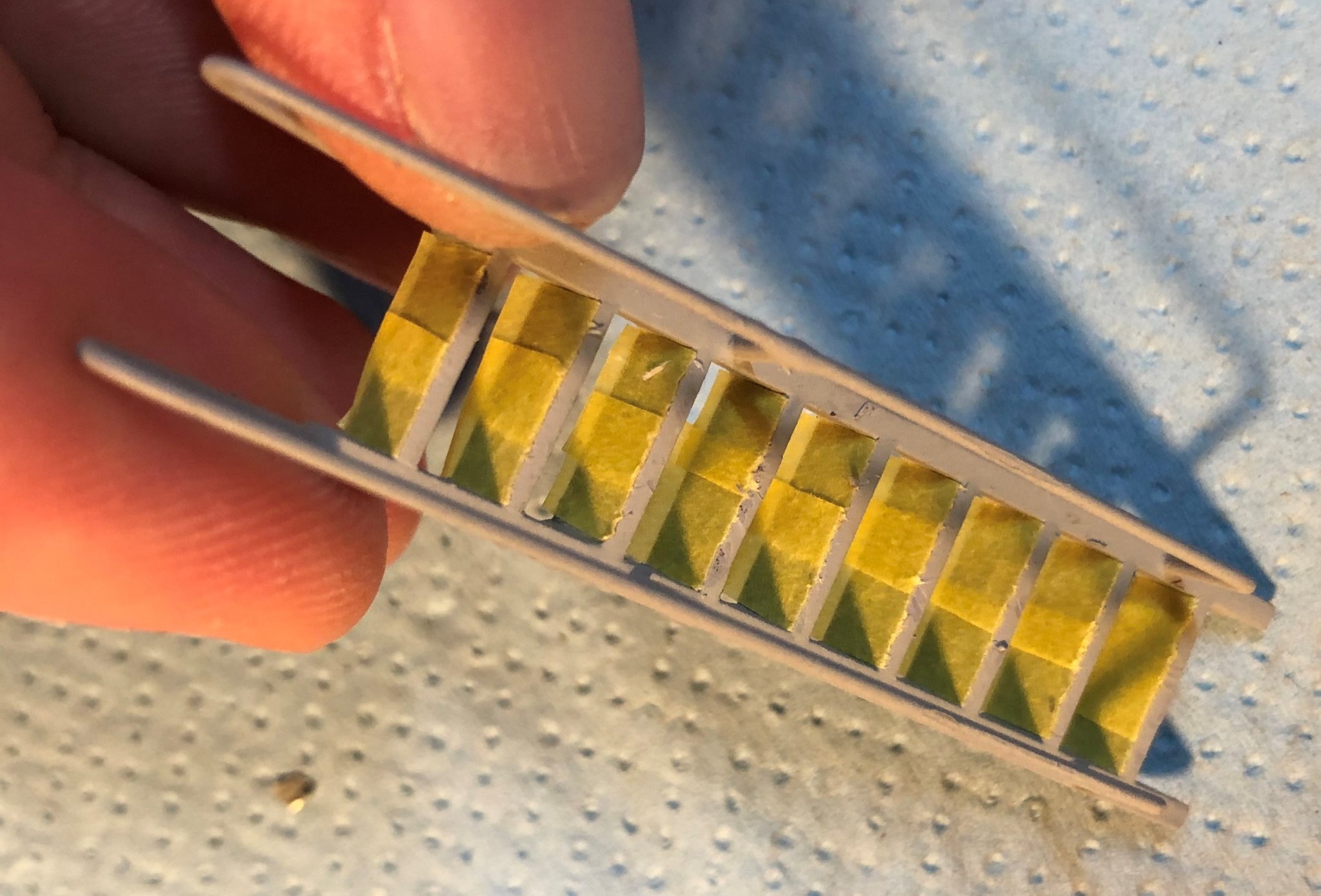
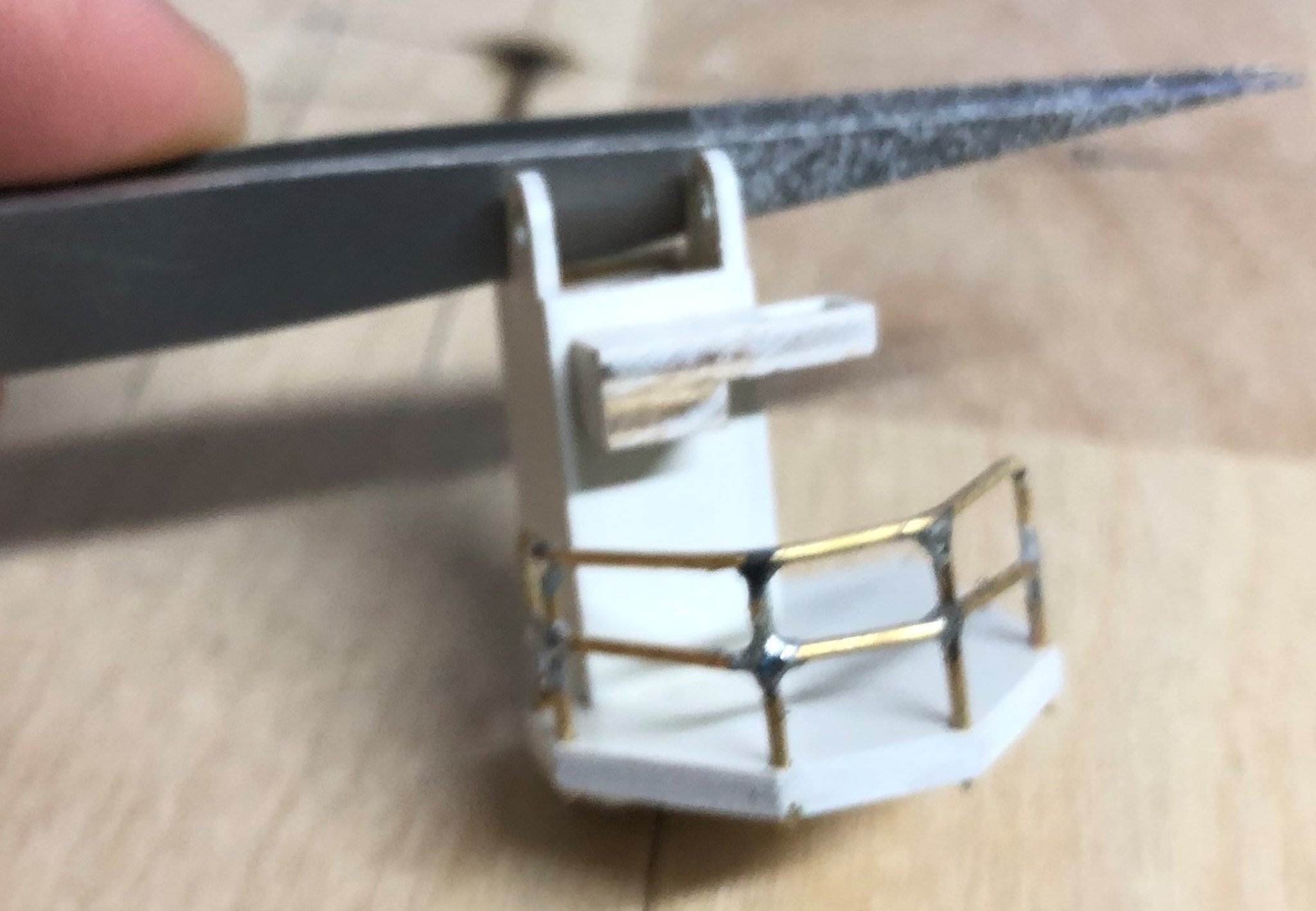
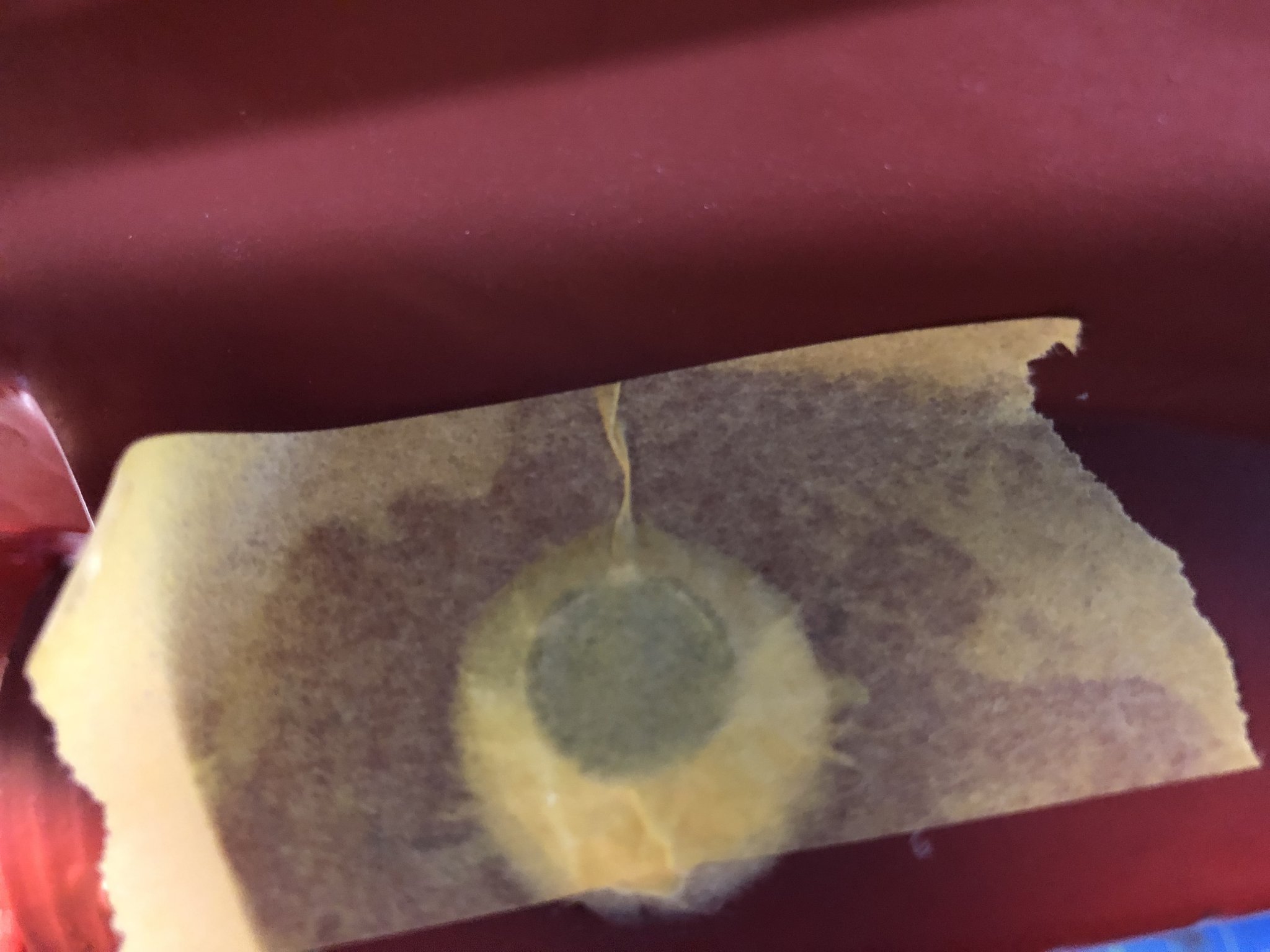
Hello All, today I will start with a short up to speed post and finish up with by showing You the fully glued stern thruster body. As I said in a previous post, I am soldering all of the handrails and other metal components, as the masts. The biggest problem with the soldering was, that the kit supplied rail stanchions were made of aluminium. Which is possible to solder, however, even after I acquired the proper flux, it was difficult to get satisfactory results. The cornwallmodelboats.co.uk shop shows them as brass, but in the description is, that they are made of aluminium. Also the height of these is only 12mm, which in the scale of the model, 1:75, gives the height of 900mm, or 90cm, which for a ship safety feature preventing falling overboard seems to me, to be just a bit low. Also the three holes on there stanchions were all 0.8mm bore, which is again too big for two reasons. Firstly, the rail wire supplied is only 0.5mm, and second, the 0.8mm diameter gives in scale a diameter of 60mm, which is good for the topmost "grabbing" rail, but is too bulky for the two lower rails, here the 0.5mm wire just looks better. For these reasons I looked for an appropriate replacement. I found the three holed stanchion from Graupner. These have the same shape, however are 14mm high and the holes are 0.8mm top, rest is 0.5mm. The new height is in scale just over 1 meter, which seems to me to be a bit better, also regarding the model, the new height is also quite fitting. Here is a sketch of both stanchions, and a picture of the new one used: Also these stanchions are made out of brass and come oxidation-free. So they are a treat to solder, but for uniform performance of the solder joints I use the Carr's Green Label solder flux for use on brass, copper, nickel and silver. I also went and bought in our local arts and craft shop a reel of copper wire with 0.8mm diameter, as the 0.5mm dia. wire was already supplied in the kit. So in the end the grabbing rail is made of the 0.8mm wire, and the lower rails are made of the 0.5mm wire. Some images of the produced handrails. The fire-monitor deck hand rail, just soldered, I use a piece of low quality masking tape to transfer the positions of the holes to a block of wood, there I solder the handrail. And fitting the rail to the coresponding piece. The rails are then primed using Tamyia metal primer in two light coats, followed by Tamiya surface primer. And later they are painted with airbrush (not at that stage on any of the handrails yet). A picture of other, already primed handrail: the last pictures show one of the 4 ladders mounted on the hull, they are now painted white and are waiting to get green sides painted, then they will be done. Now for the progress on the repairs: Form the weekend pouring, there are still holes to be covered. For this I needed to buy a new package of epoxy glue as I feared the old one was going bad. I used the UHU 90min epoxy with micro air balloons to thicken the glue, to almost non dripping state. I plugged the holes with a piece of masking tape and shoveled the epoxy in using the spatula. until it completely surrounded the installed thruster body. And last for today's post, I started installing first ballast weights in the stern with the excess epoxy I had made. Cheers George


- 90 replies
-
- 4
-
-
- fairmount alpine
- billing boats
- (and 1 more)
-
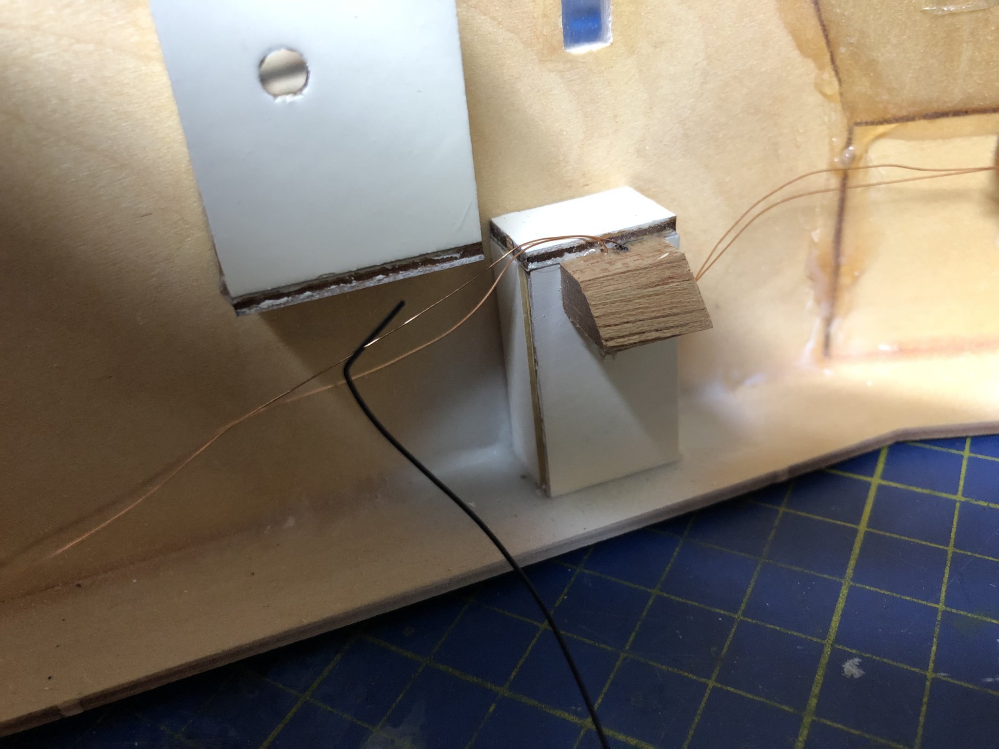
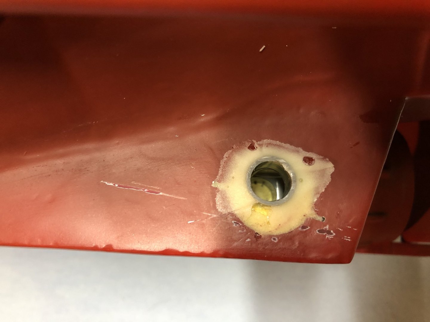
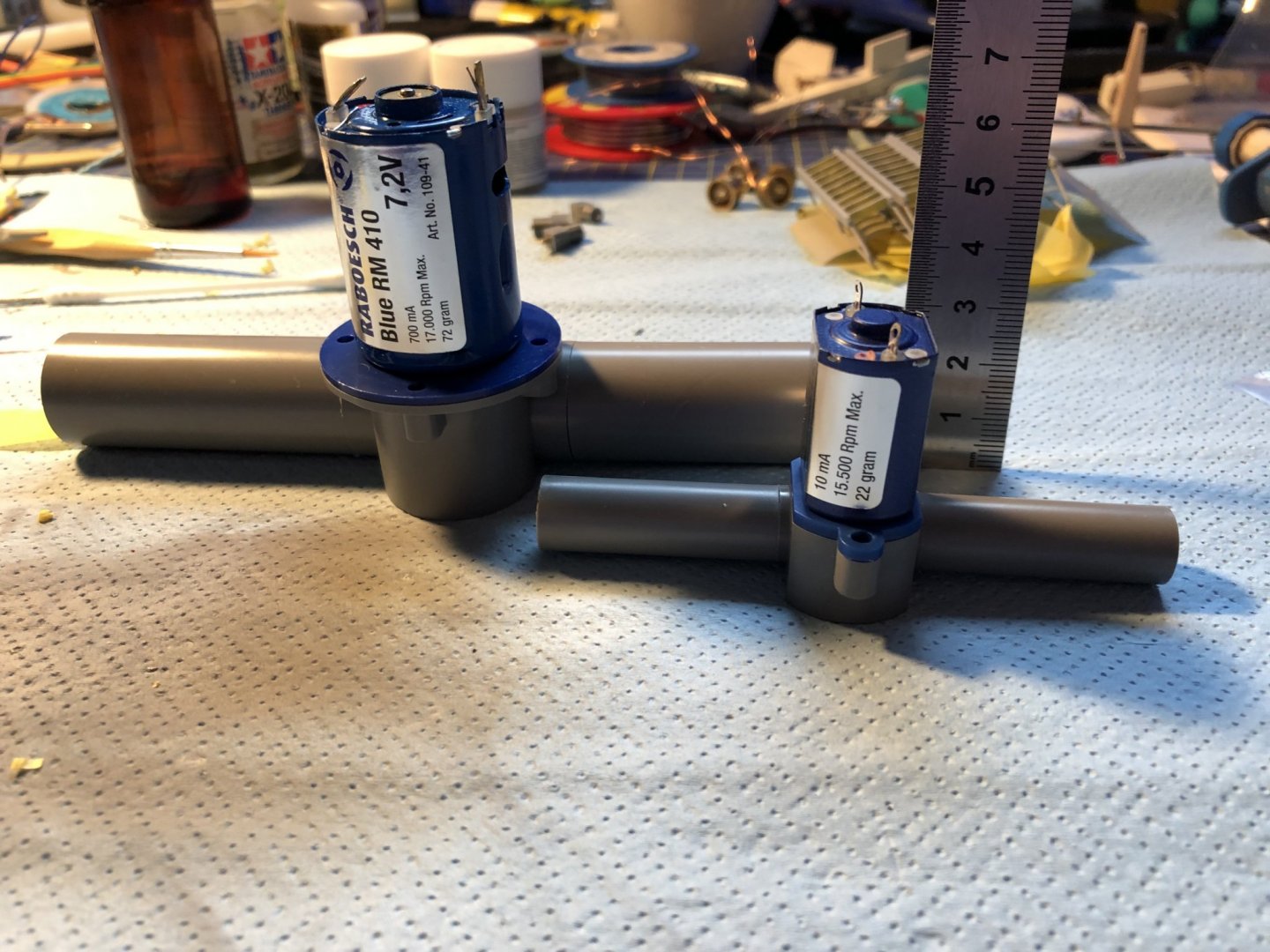
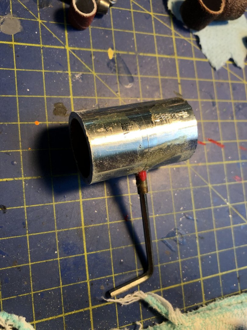
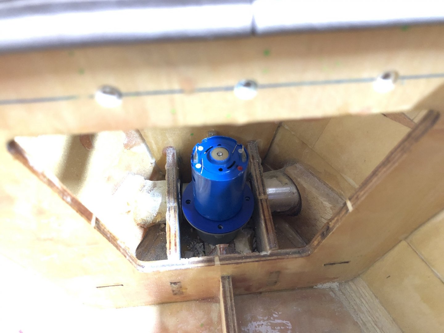
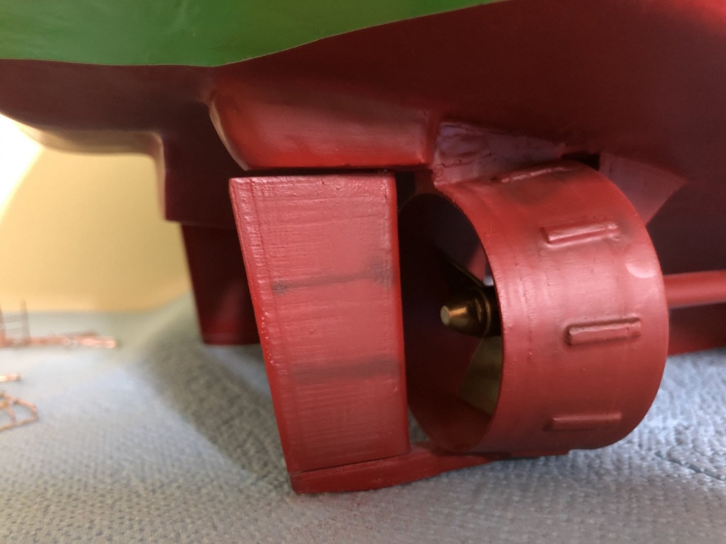
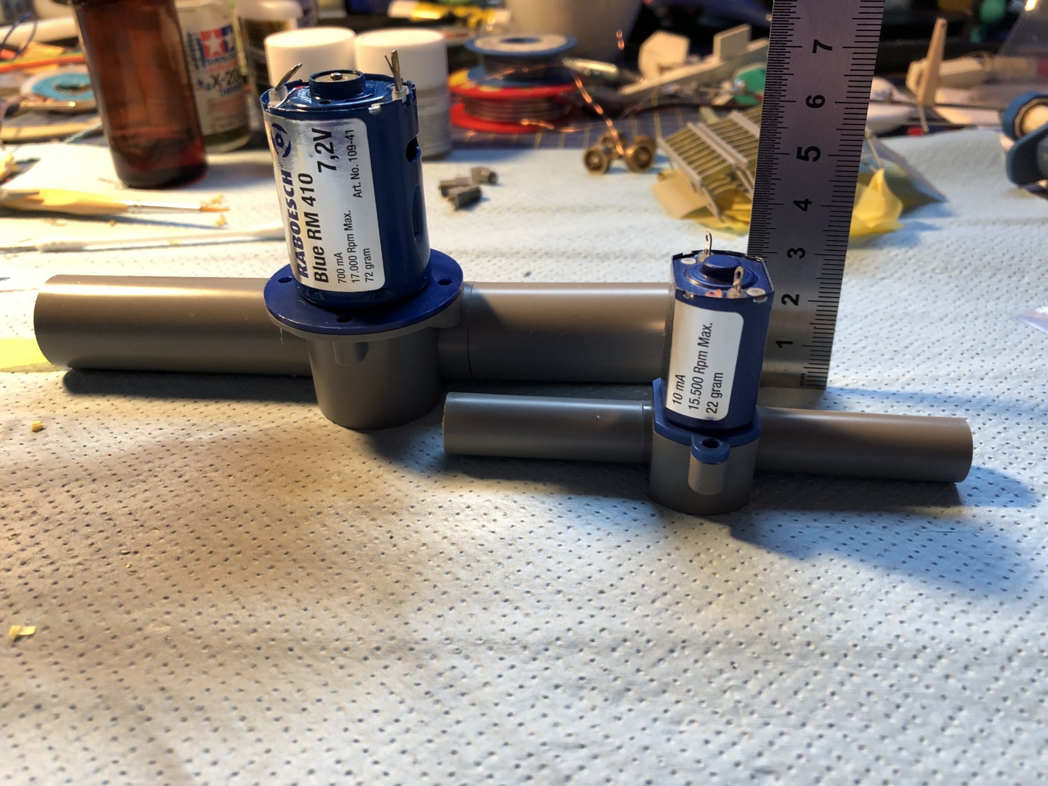
Hey Peter, Yes I was considering the 24mm thruster, but then instead went with the smaller one, the 22mm one. As this diameter does not have the coned channels. This can be seen on this picture: Has straight channels running out of it. This I can use to my advantage, as the inner diameter of the build in channels should be also 22mm, or very close to it, this should allow me to theoretically just slide the new unit in place. The only problem now is a 1mm gap that is there after I sawed out the old unit. I wanted to change it with as little work on the exterior as possible, as I don't want to repaint the hull for the 3rd time already. Also I can see you made it quite bullet proof, so to speak, I don't think the forces from the bow thruster will be so great as to need excessive reinforcement in place. So I plan to add I bit of, probably balsa wood to create a bigger surface for the thruster to be glued on, but I will see, maybe I will do a quick test of the thruster in a sink, to see how powerful it actually is... Cheers George
- 90 replies
-
- 4
-
-
- fairmount alpine
- billing boats
- (and 1 more)
-
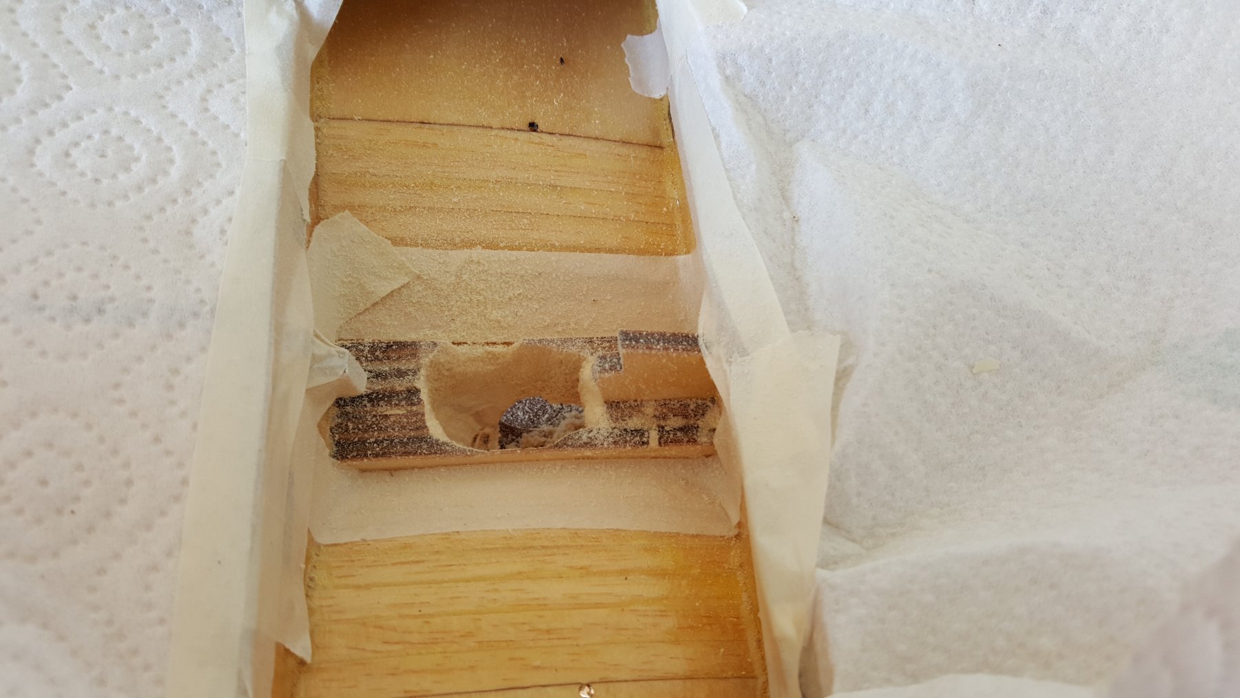
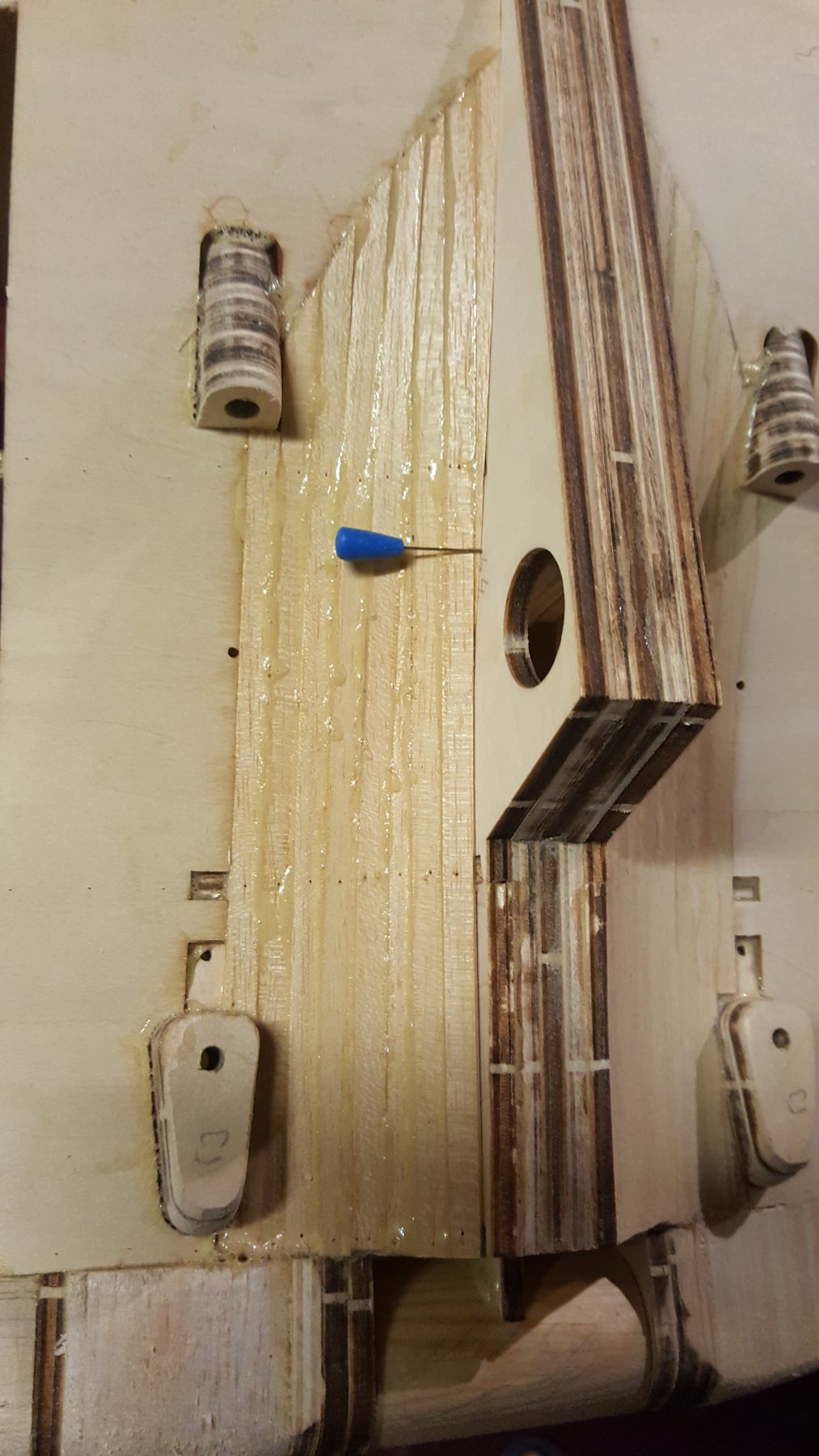
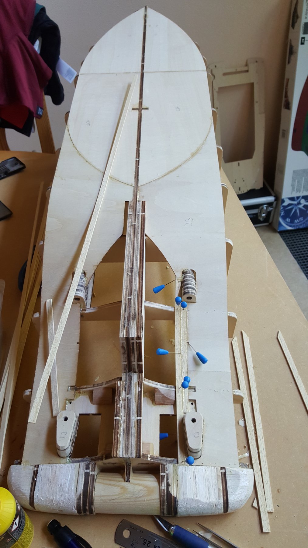
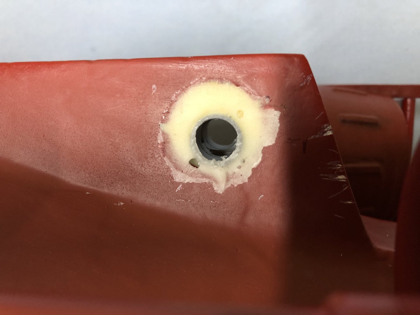
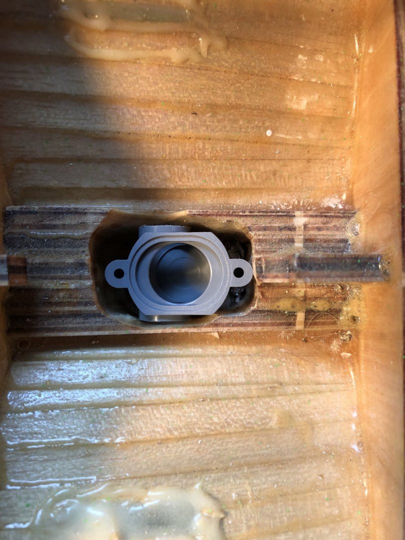
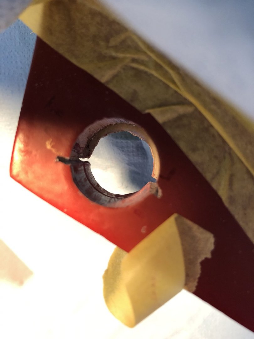
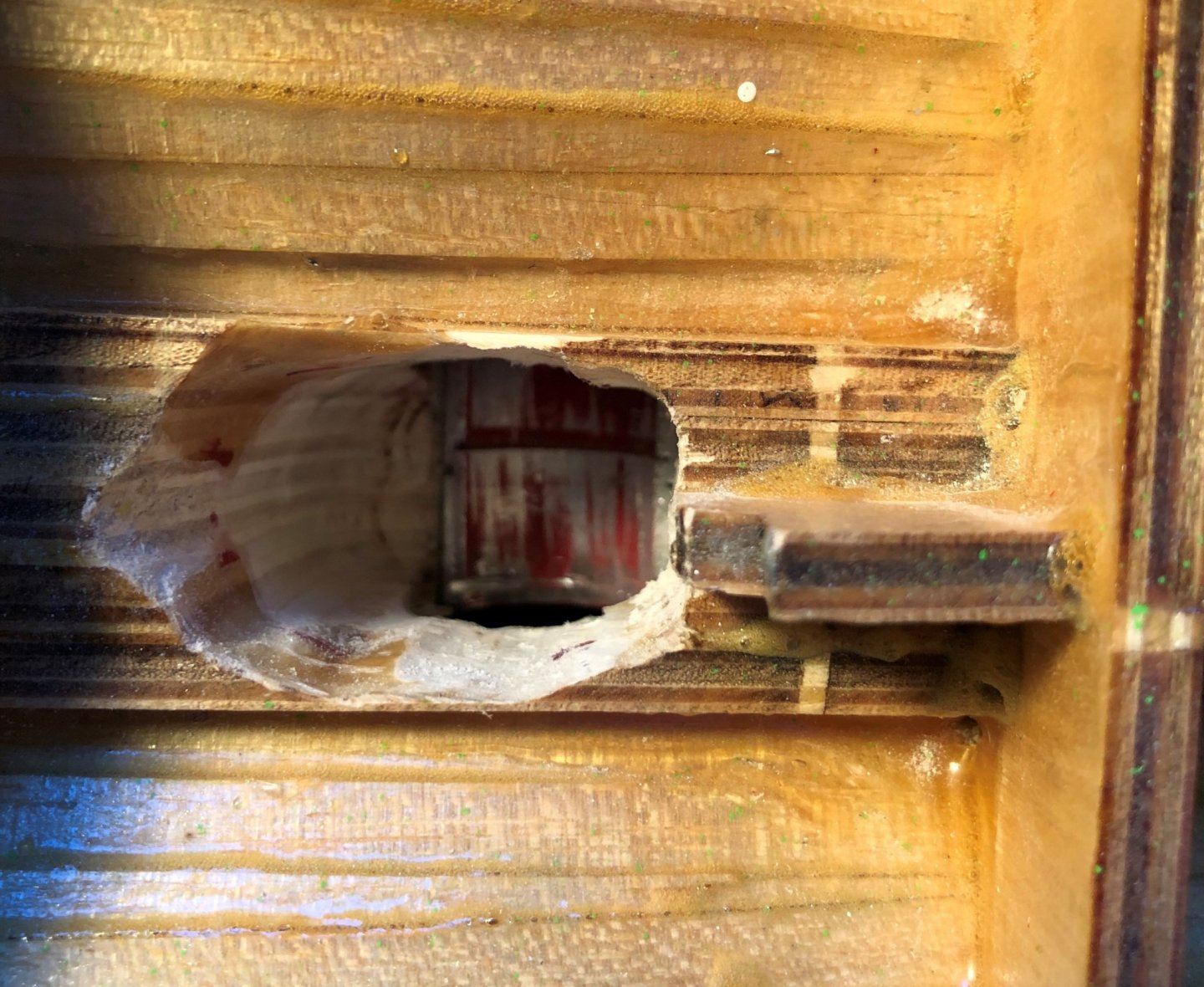
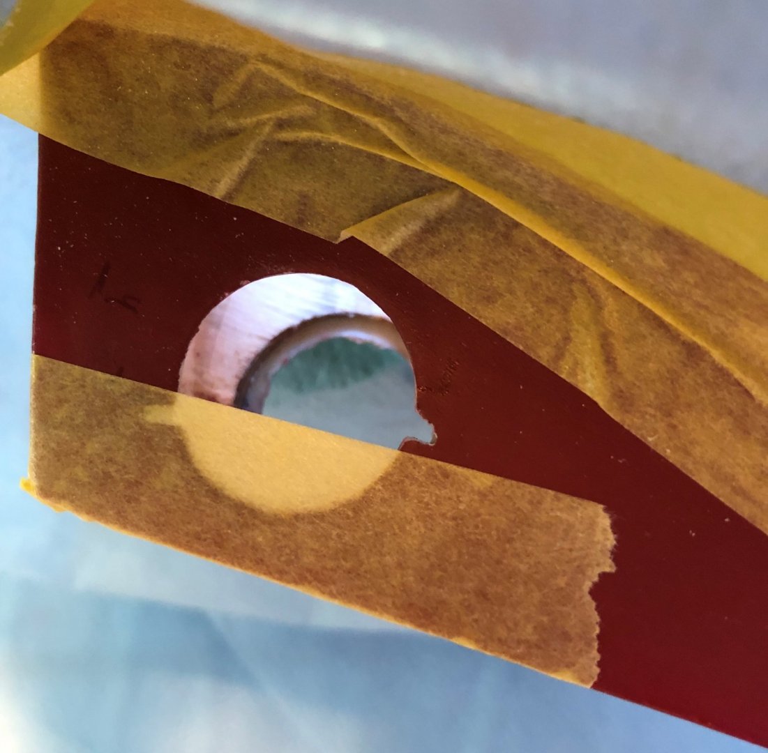
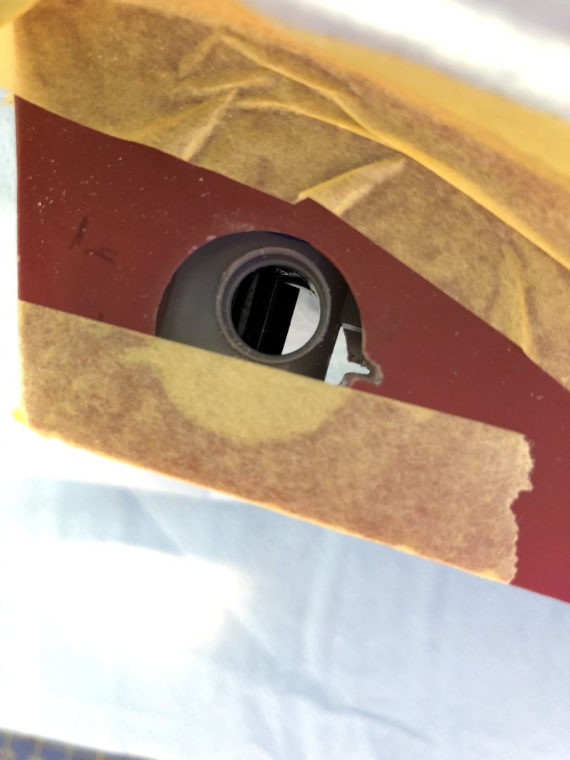
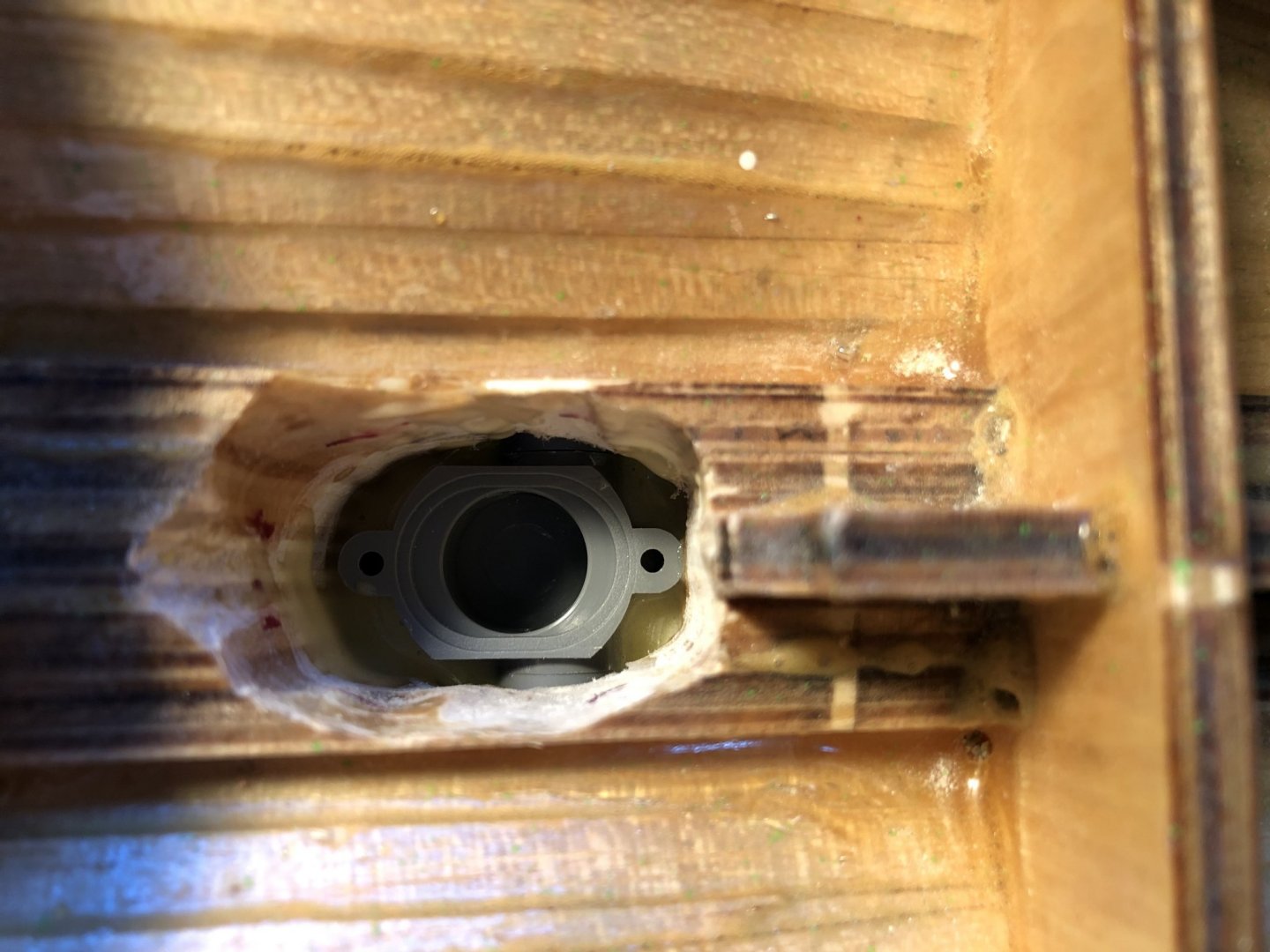
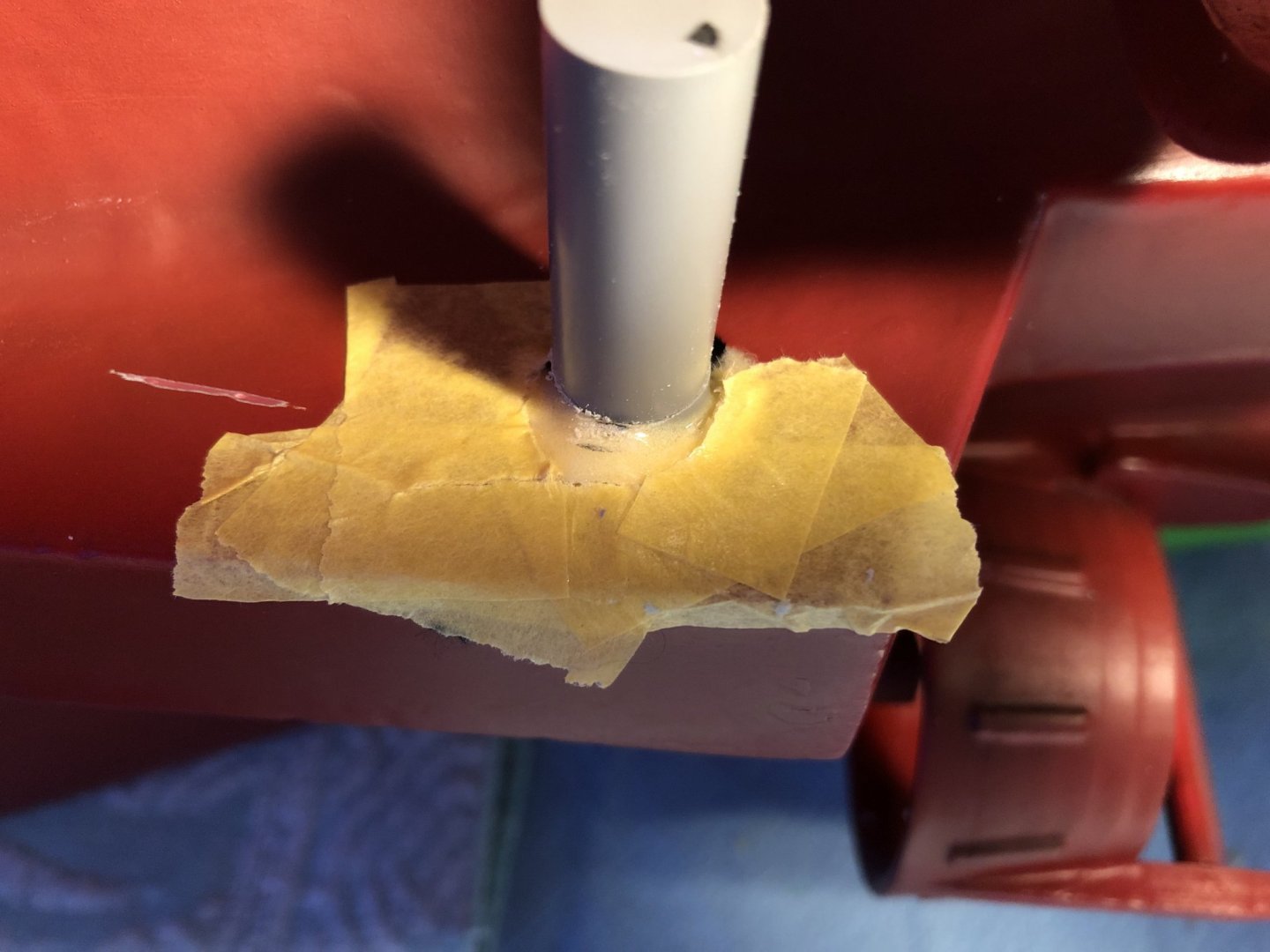
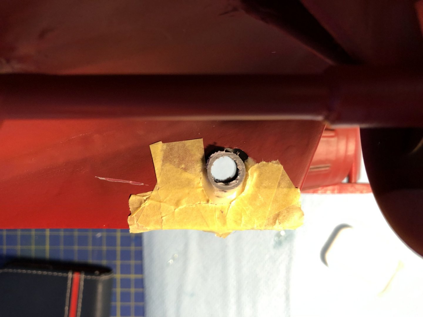
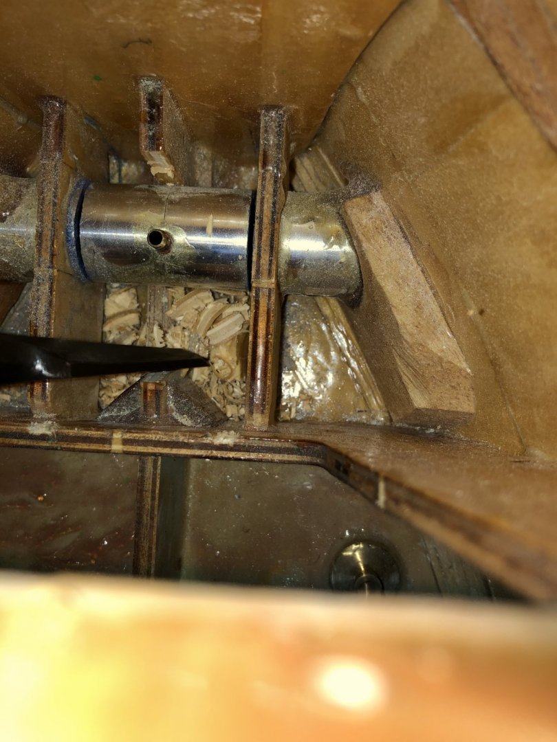
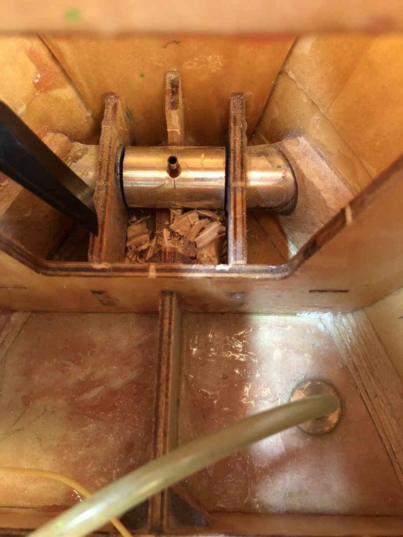
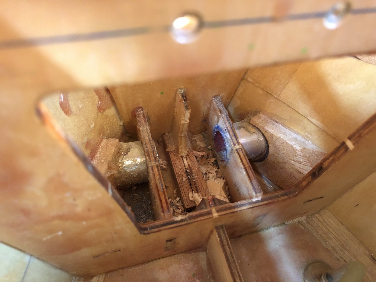
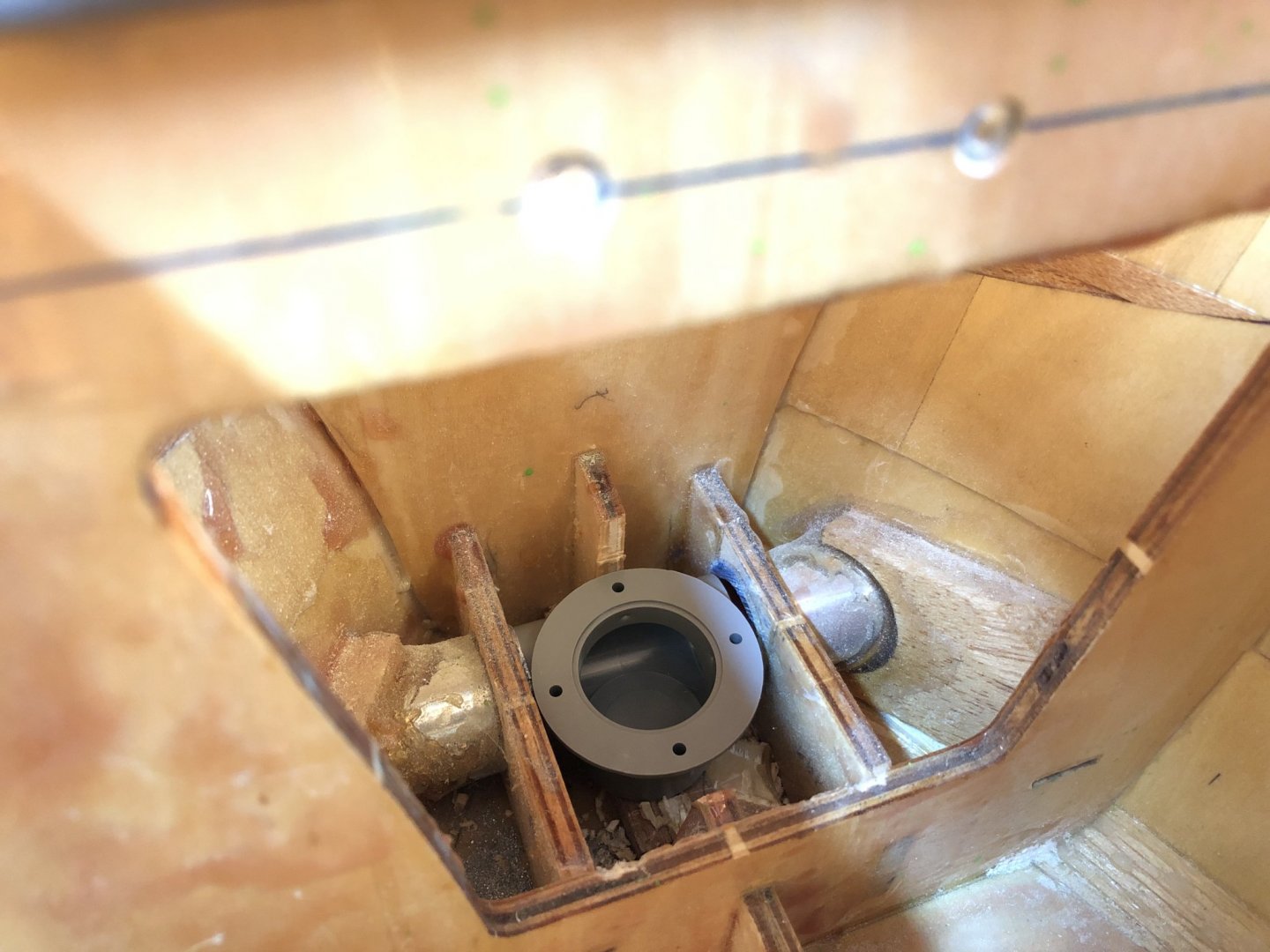
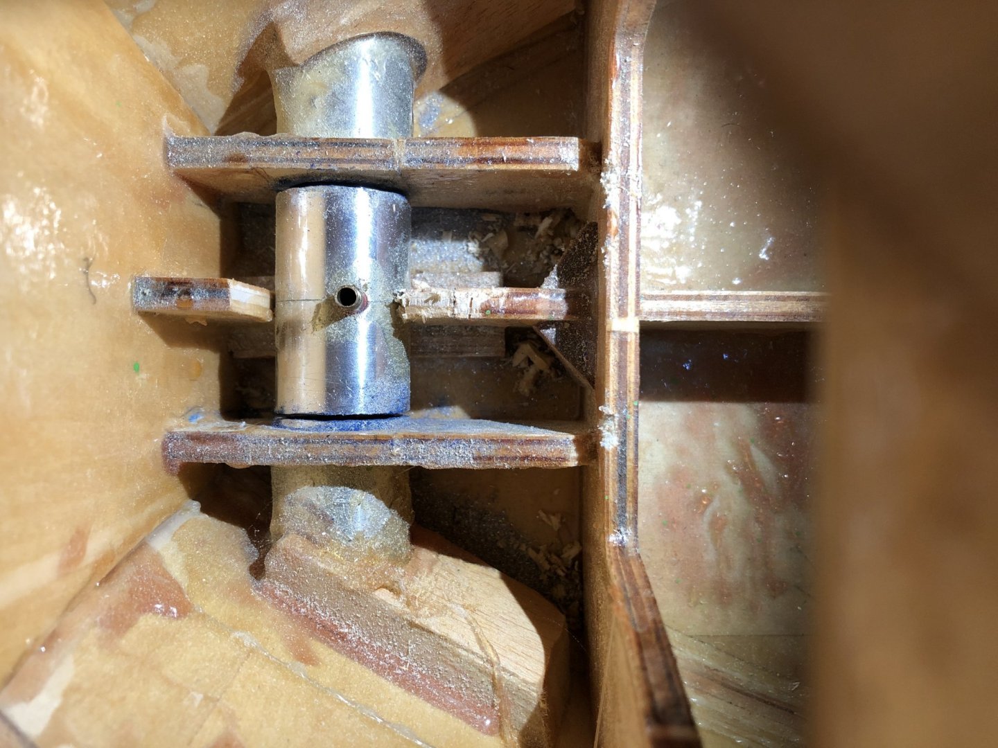
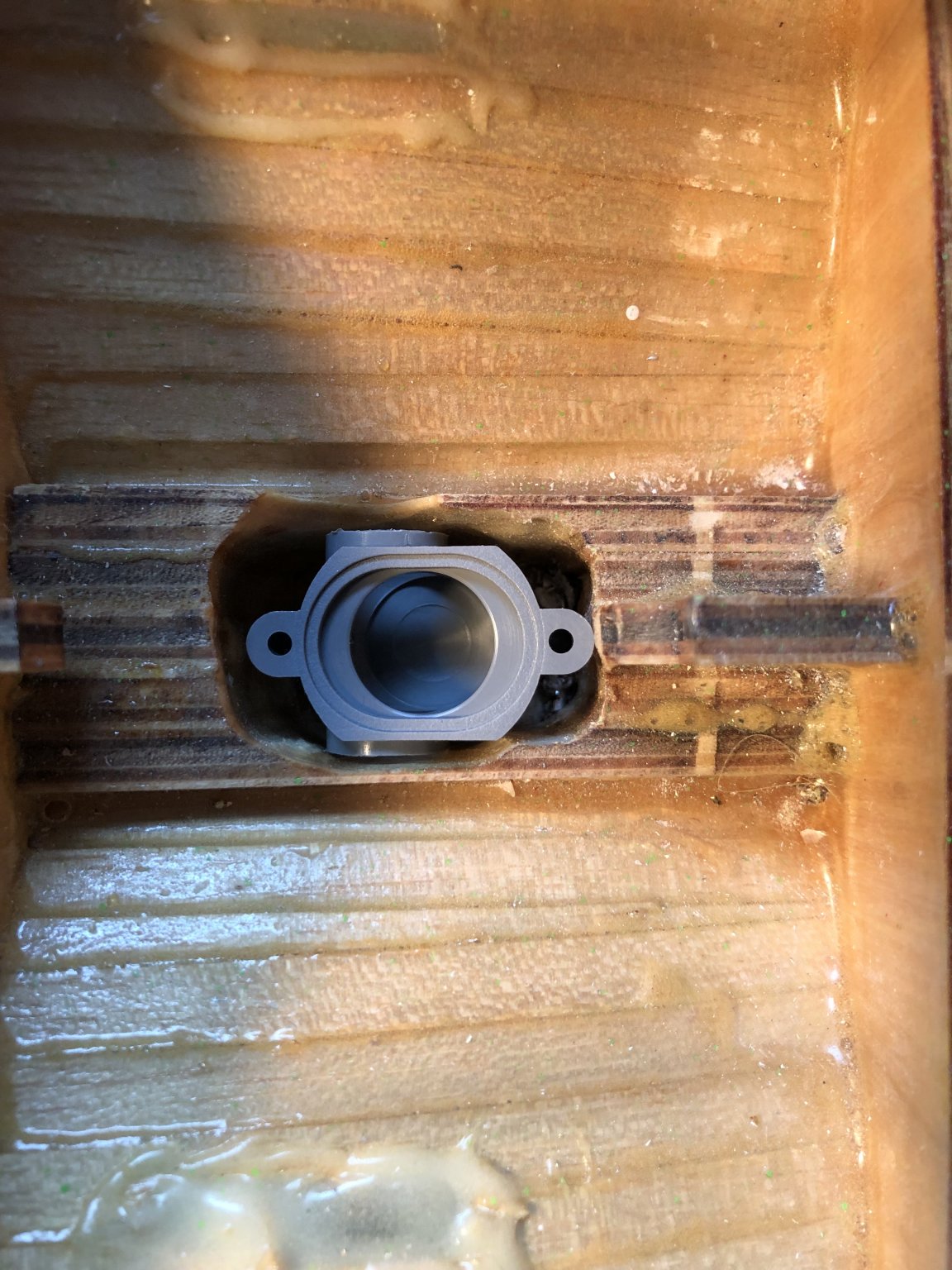
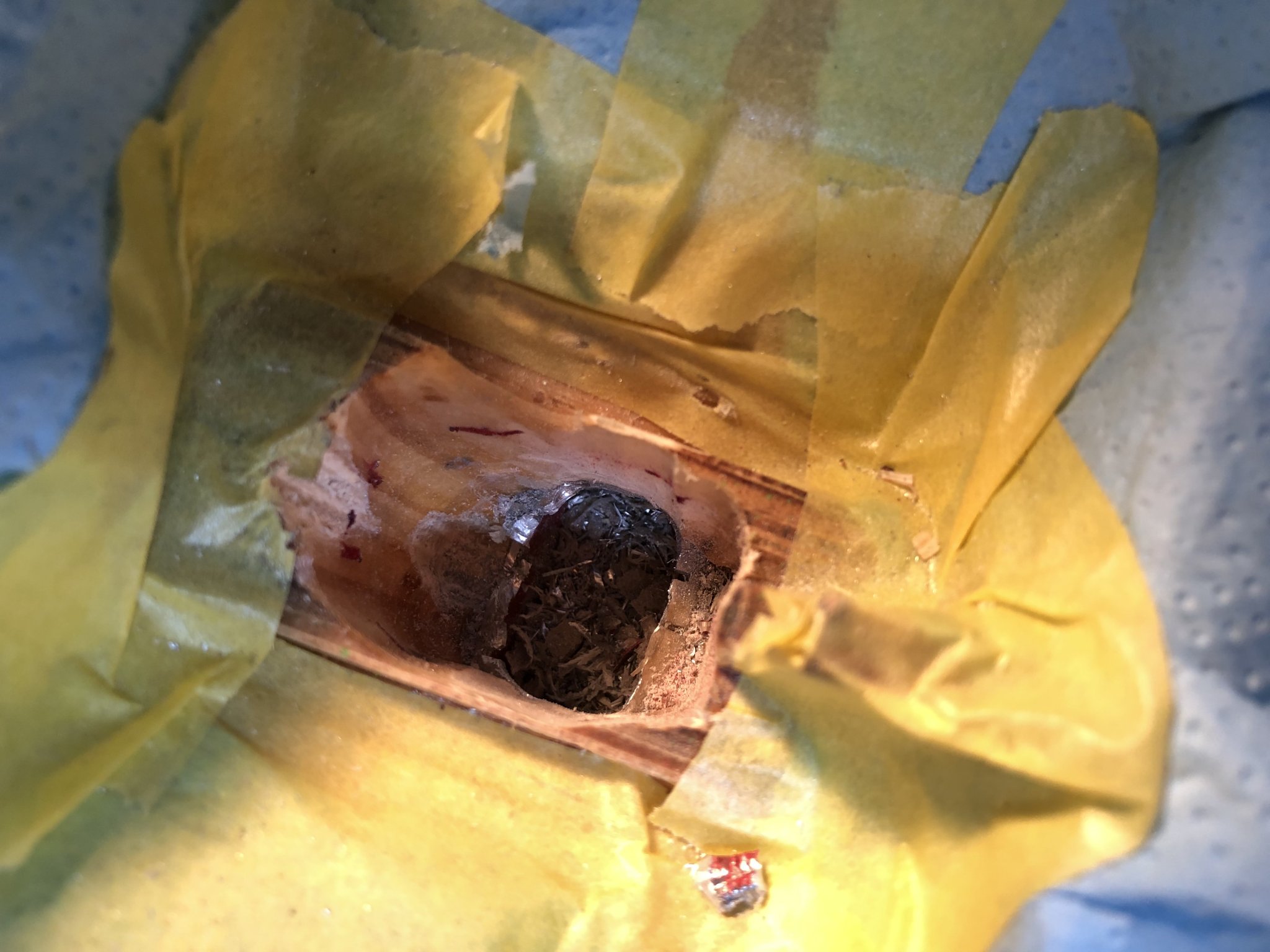
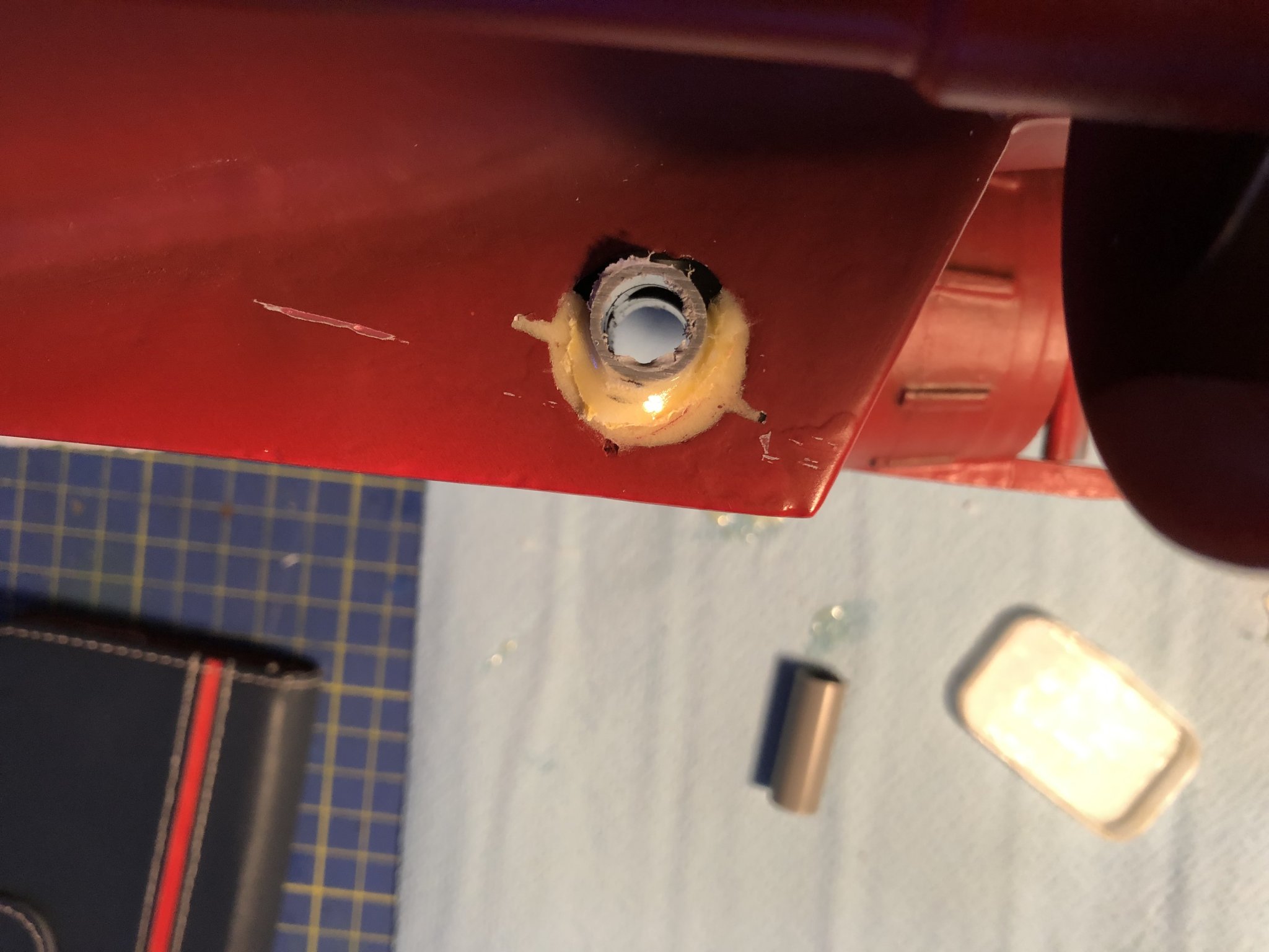
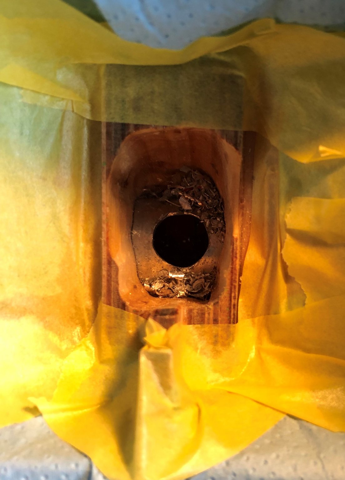
Good day to all, Today I will do an update of the build, regarding my progress during this weekend. I forgot to take some necessary pictures for the getting up to speed with the build post, so that will follow tomorrow. As I wrote on Saturday I got the new thrusters in. I went with the Raboesch 22mm OD thruster for the bow, and the mini thruster for the stern. I then spent the rest of the weekend getting rid of the old system in the stern. In the end I managed to peel off the top part of the Alu tube, and subsequently I sanded out the keel to accommodate for the new thruster body. Let the pictures speak for themselves: Operation in progress. First fitment picture to the left. Picture to the right, finished alu tube removal. I went and took a metal saw to it, I sawed the tube in "halves", and pried the top hlaf out. Top view of the prepared hole, I scratched the paint of the Alu a bit to improve the adhestion. On the right picture, preparation fo the initial epoxy pour, making a dam out of tape. Checking the placement of the thruster body, looking for squareness to the hull exterior, and first pour of epoxy (the yellow hint in the bottom right conrer of the hole. After the curing of the epoxy, some over flow is visible, this also covered parts of the masking tape, this however should not pose a big problem, as the parts with the tape are protruding outside the hull overall shape and will be sanded off. The later picture shows the thruster after I cut off the excess pipe. And the last picture shows how the stern thruster looks right now. I didn't finish the epoxy pouring, as I run into issues with the used epoxy, it took too long to cure and even after 2 hours still had rubber surface. I blame it on the age of the epoxy, as it is well over 2 years old... I will check today in the evening, hopefully it cured entirely. But nonetheless I will go and buy a new can of epoxy to finish up the filling. For the bow thruster I used a chisel to remove a part of the keel right behind the thruster position, this created enough space for the new thruster body. I removed the old body by sticking a hex key into the shaft hole and prying it out, which was an easy task. The initial state of the bow thruster, after the sawing of the alu tube, covered in a previous post, In the process of chiseling of the excess keel. Finished with the chisel. The hull after prying out the non used part of the old thruster system, and the pried part. Dry fitting of the new thruster body. Cheers George


- 90 replies
-
- 5
-
-
- fairmount alpine
- billing boats
- (and 1 more)
-
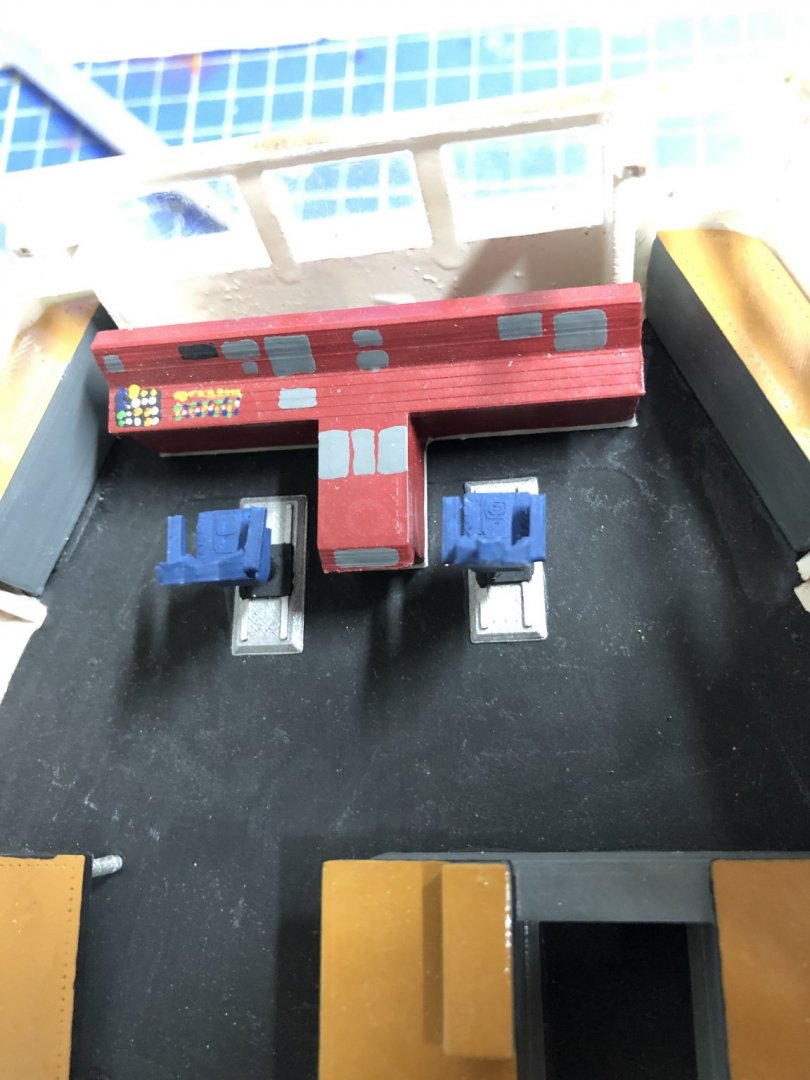
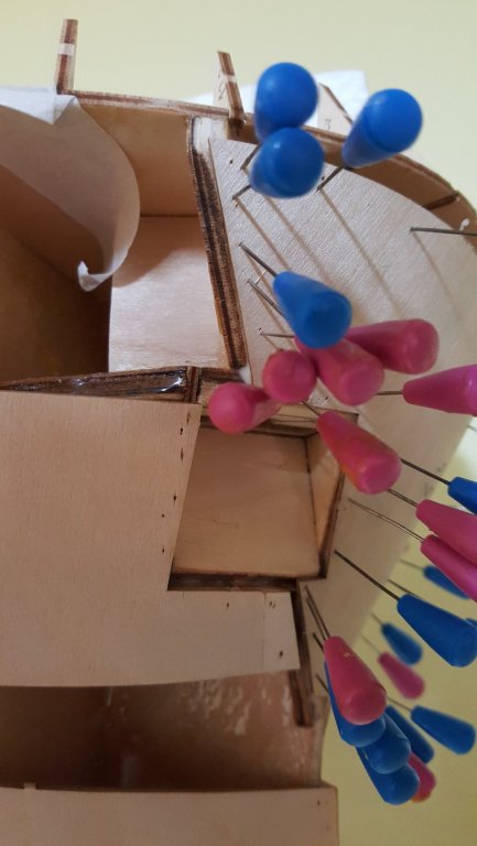
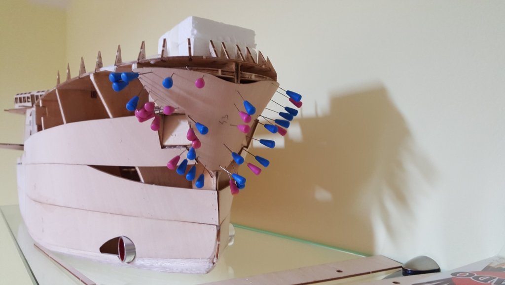
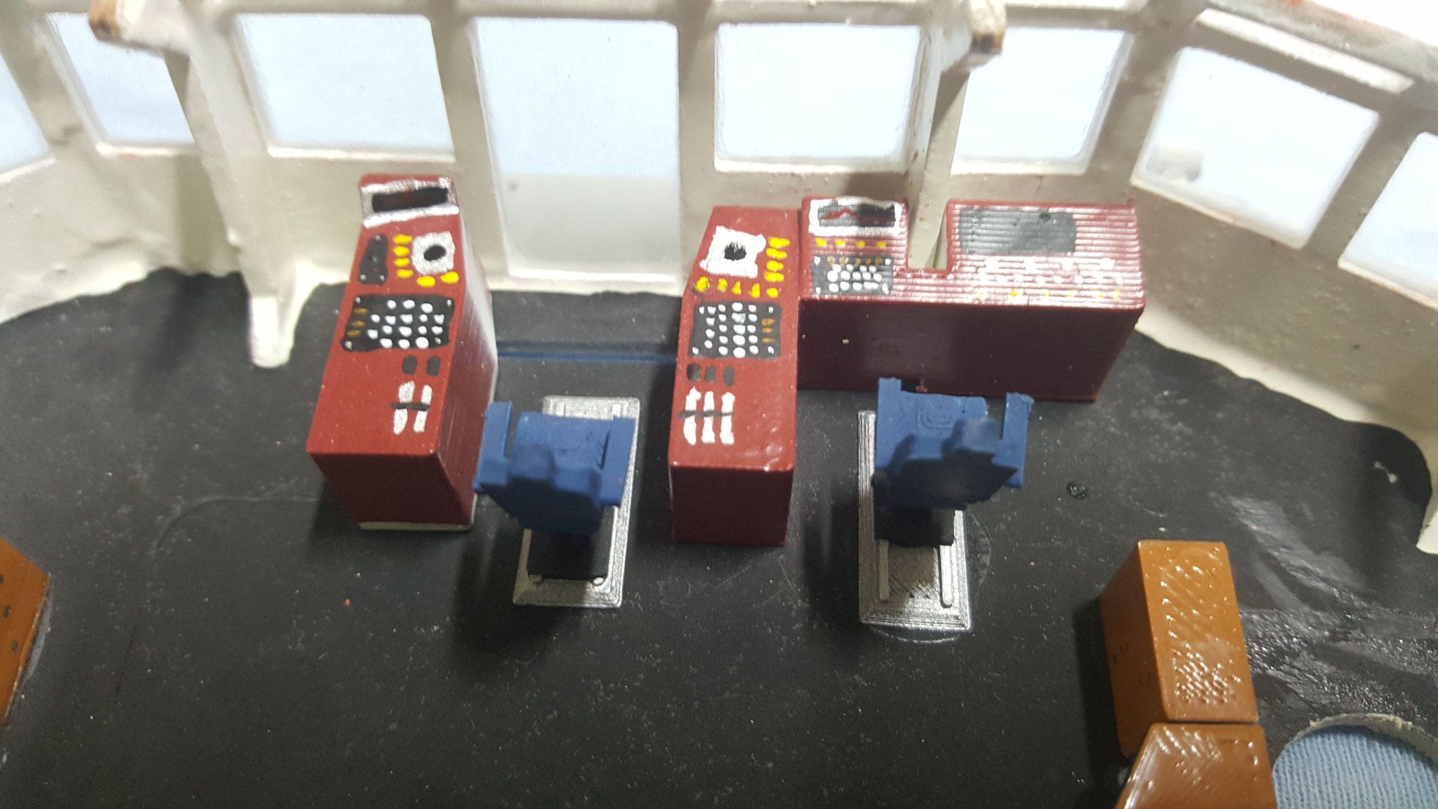
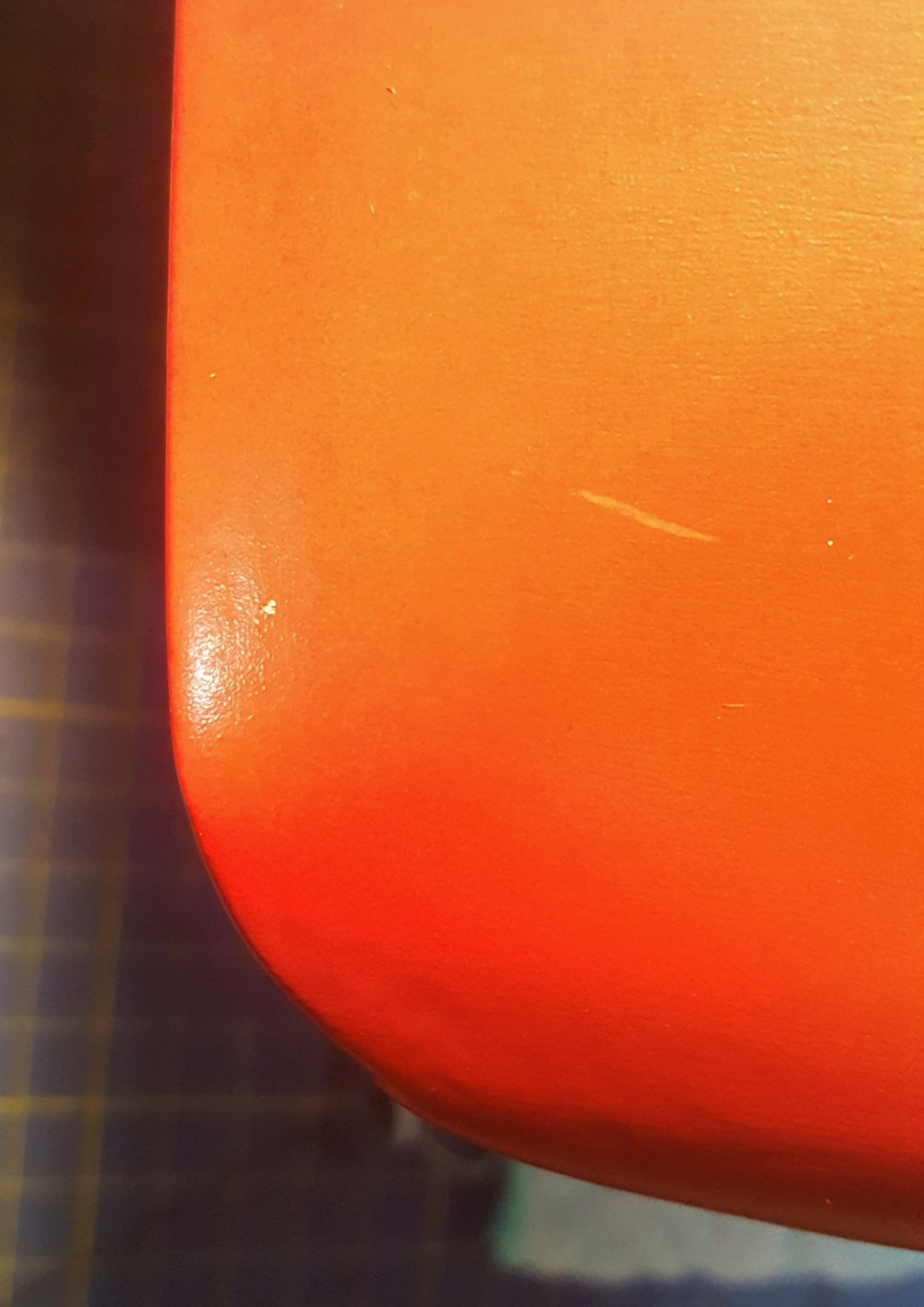
Hey Peter, oh thank you. Yeah I can imagine, how difficult your build will get with those modifications. But it will be that much more interesting to see how you will tackle those challenges. And some mild progress on my build: I increased the amount of collour dots and blobs on the control panels: And some teaser of what is to come in the following posts, the thrusters cane this morning. So I am working on the holes in the hull.. why I hate working around painted model: Paint scratches and chips, due to tool handling.. I will be repairing the chips after everything is done.


- 90 replies
-
- 4
-
-
- fairmount alpine
- billing boats
- (and 1 more)
-
Hey Peter, I have seen this site before 😄 However I don't really want to buy something I can, to some degree make by myself... But that doesn't mean, they don't have some very interesting things on offer. Regarding the towing winch, from model, it seems to be almost impossible to incorporate, to you now the model look big, but wait, until you start adding the electronics, it will be full in no time, I was surprised as well how fast, there was almost no space at all... And I even went with the most space conserving battery option there is to my knowledge... But I can't wait to see how yours will turn out to be, with all the interesting mods you have done. Cheers George
- 35 replies
-
- 1
-
-
- fairmount alpine
- billing boats
- (and 1 more)
-
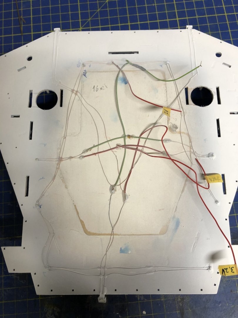
Hey Popeye, for now I don't really have a schematic, just tags with the voltages... 😀 But I will be drawing at least a legend once I start gluing the sections of the superstructure together, because as it is now, it is quite sufficient, as most of the wires condense to sort of blocks.
- 90 replies
-
- 1
-
-
- fairmount alpine
- billing boats
- (and 1 more)
-
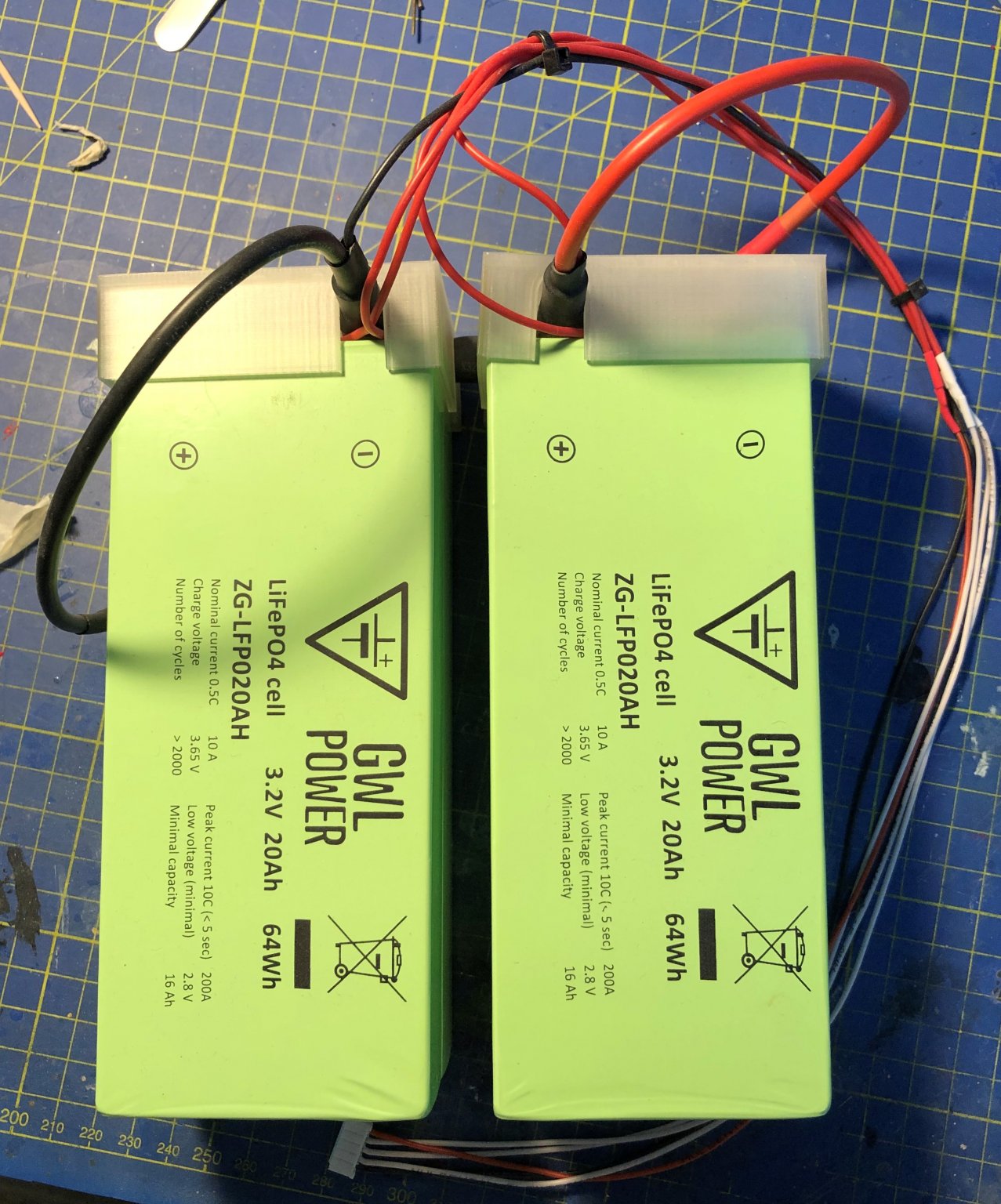
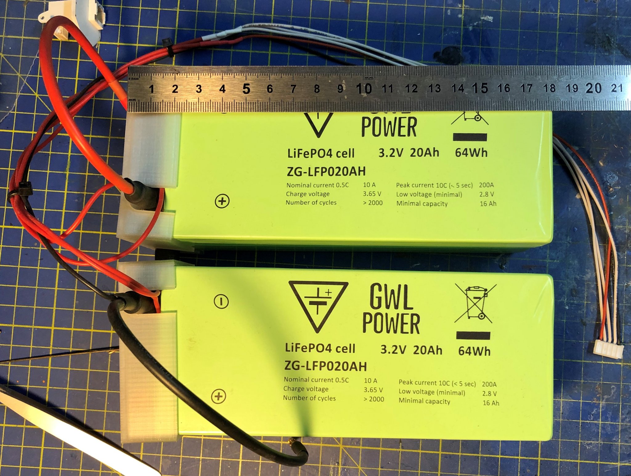
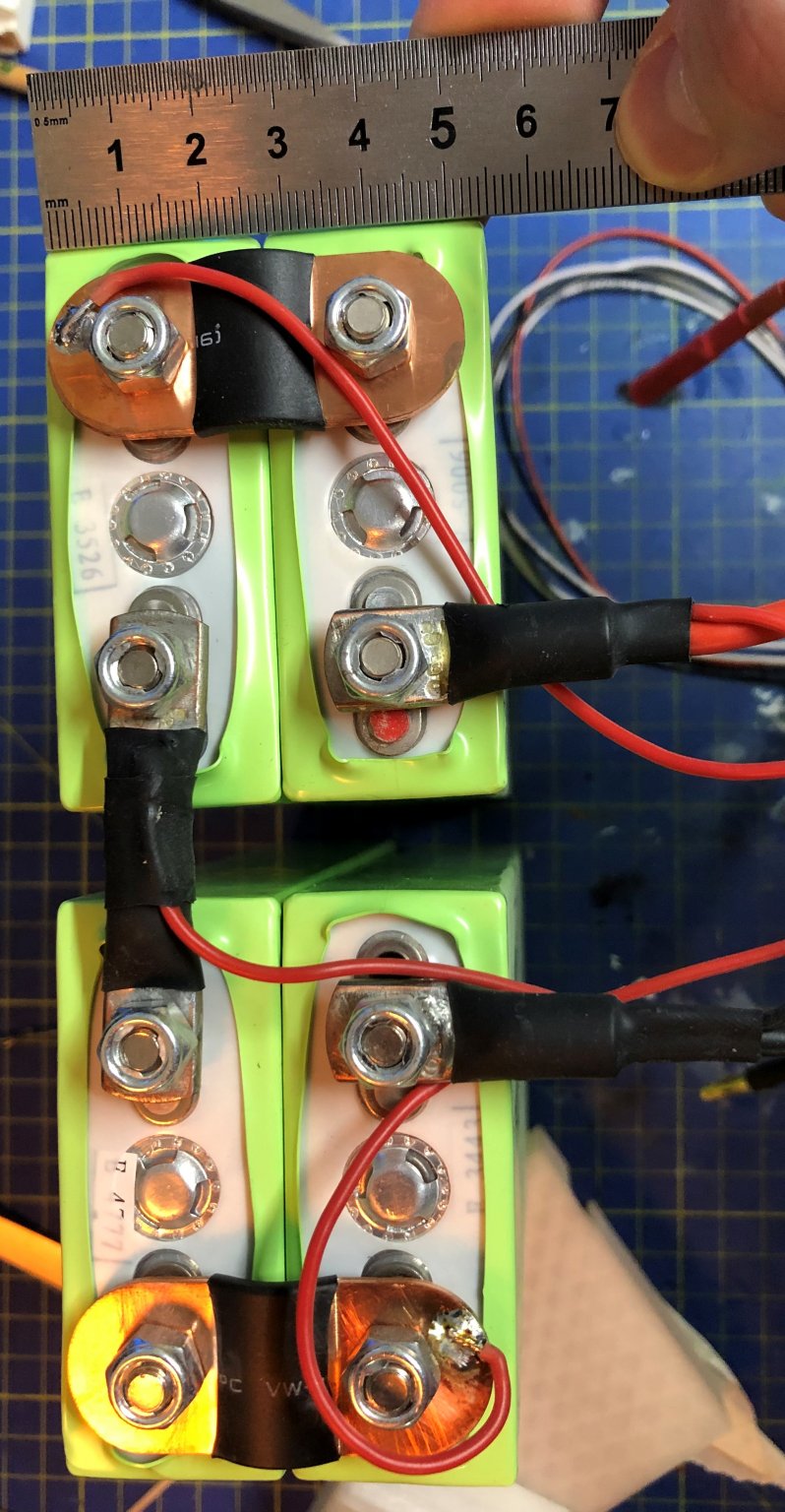
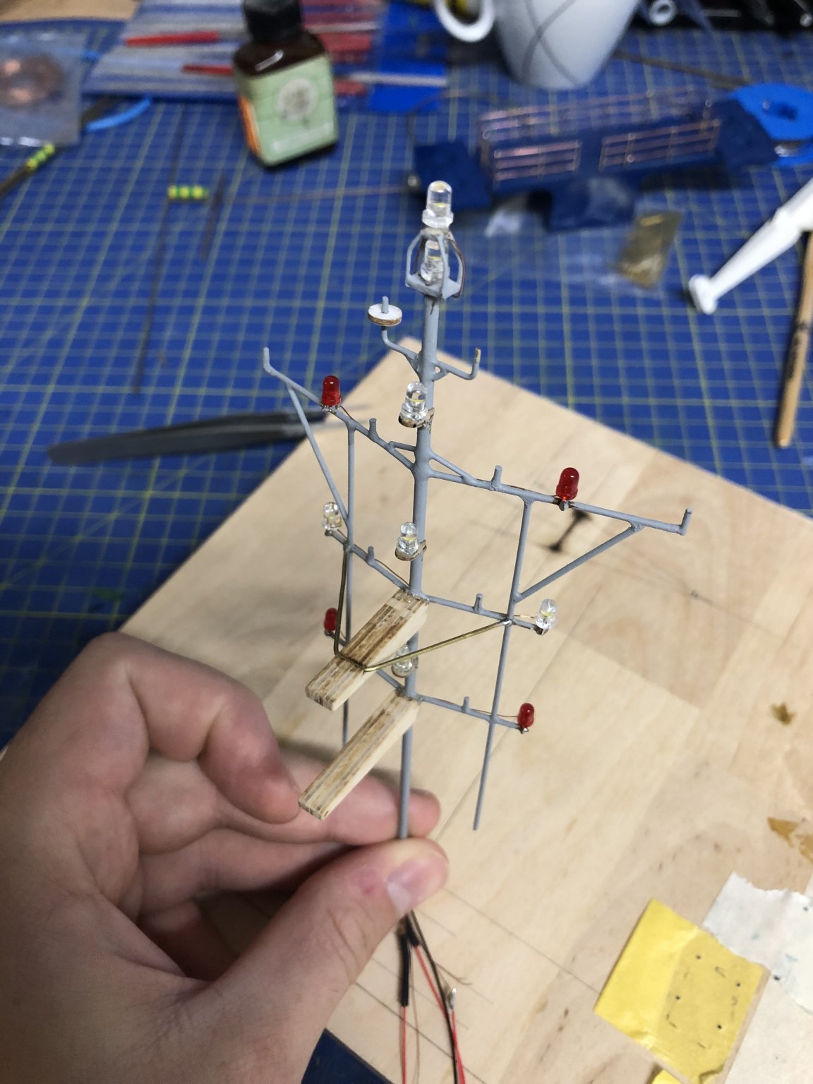
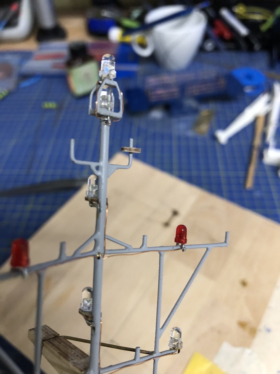
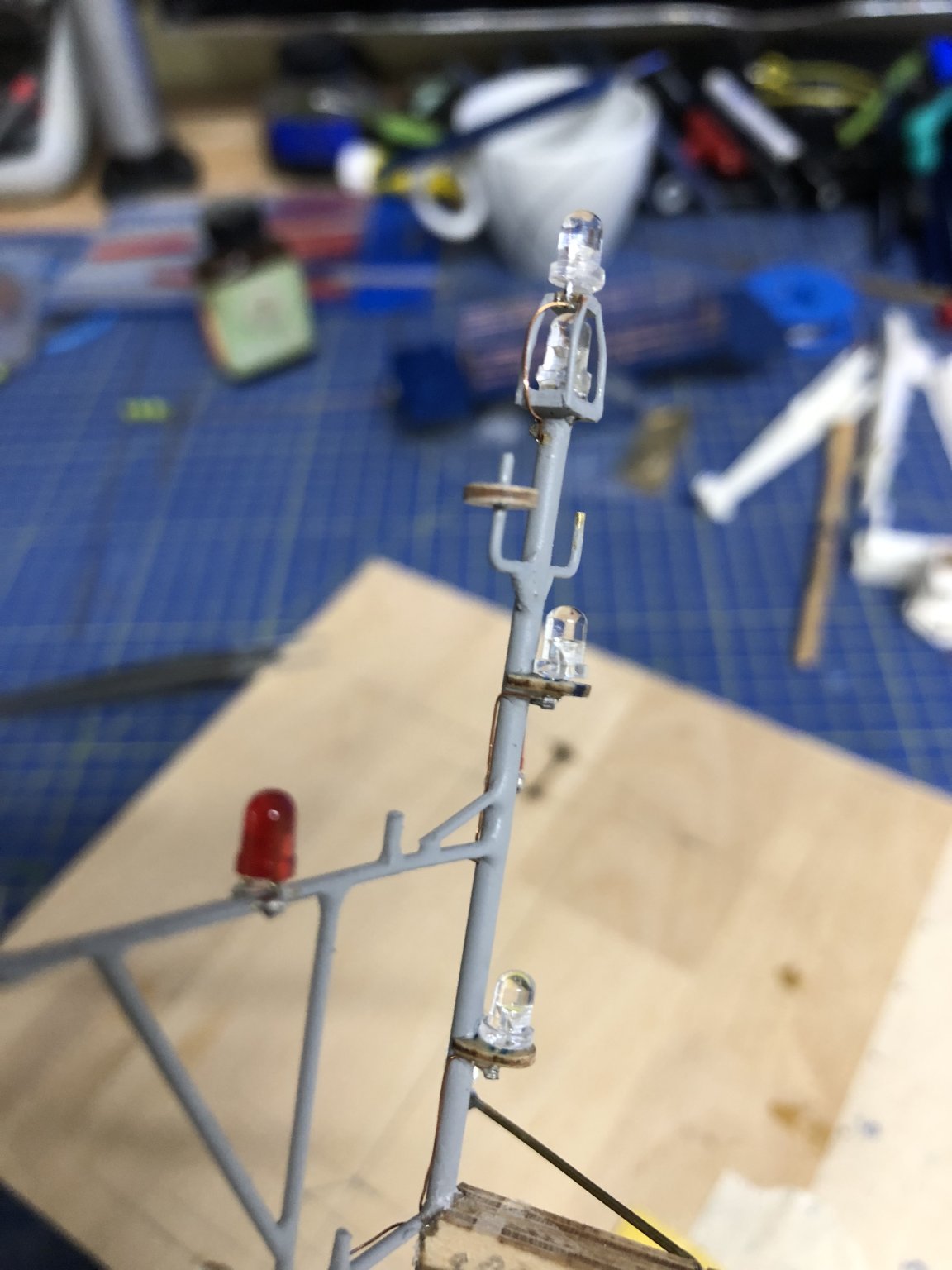
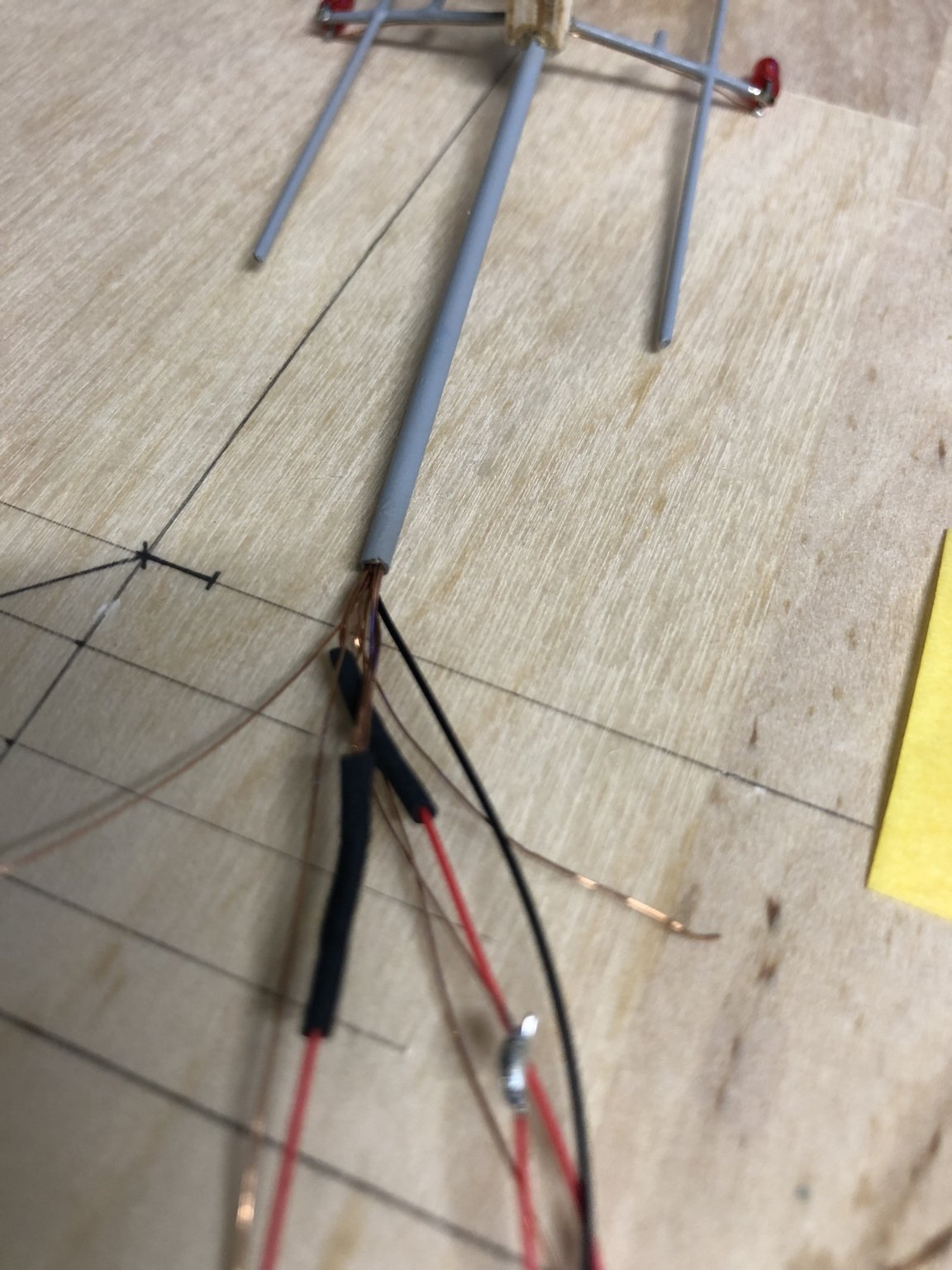
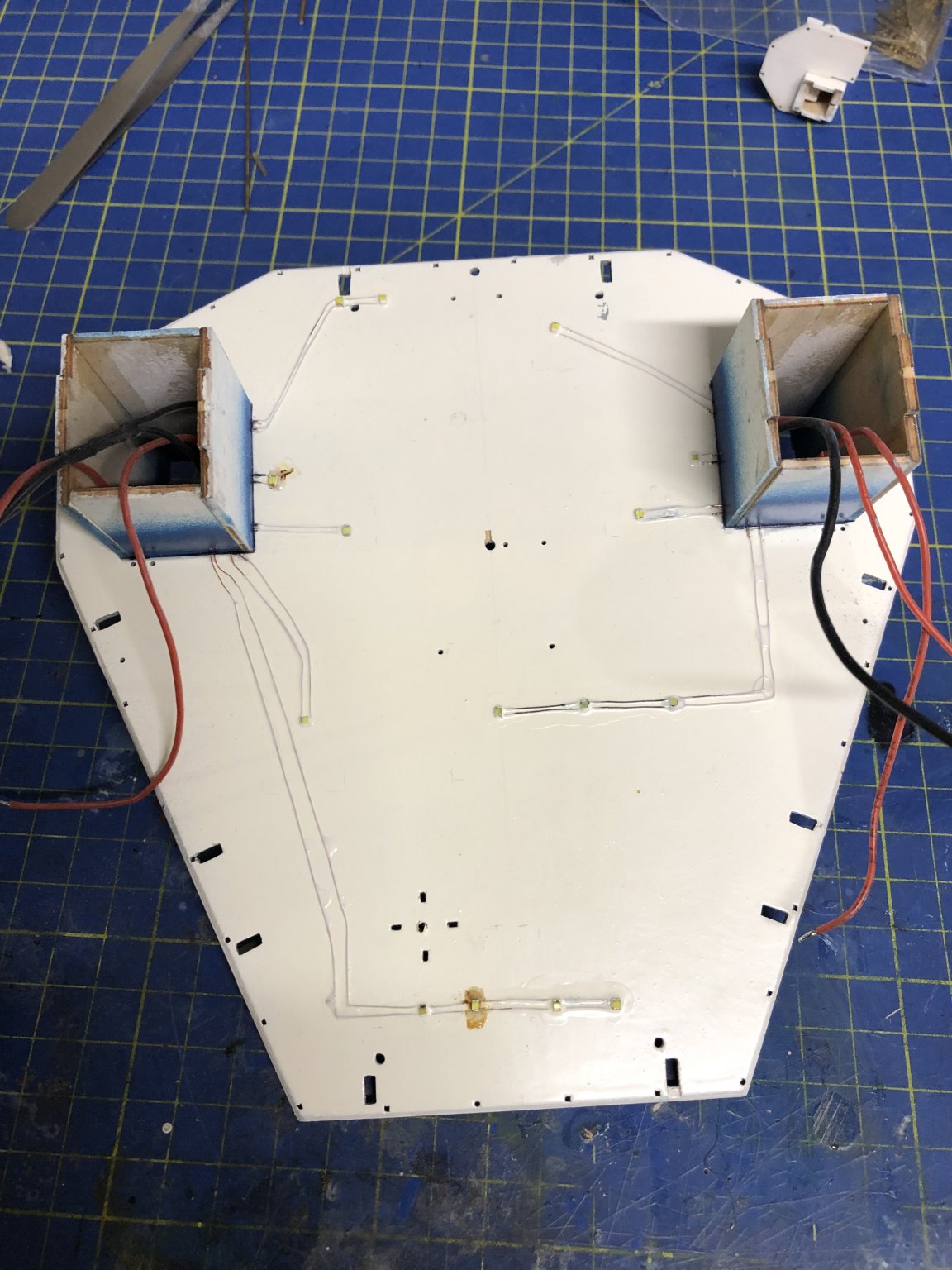
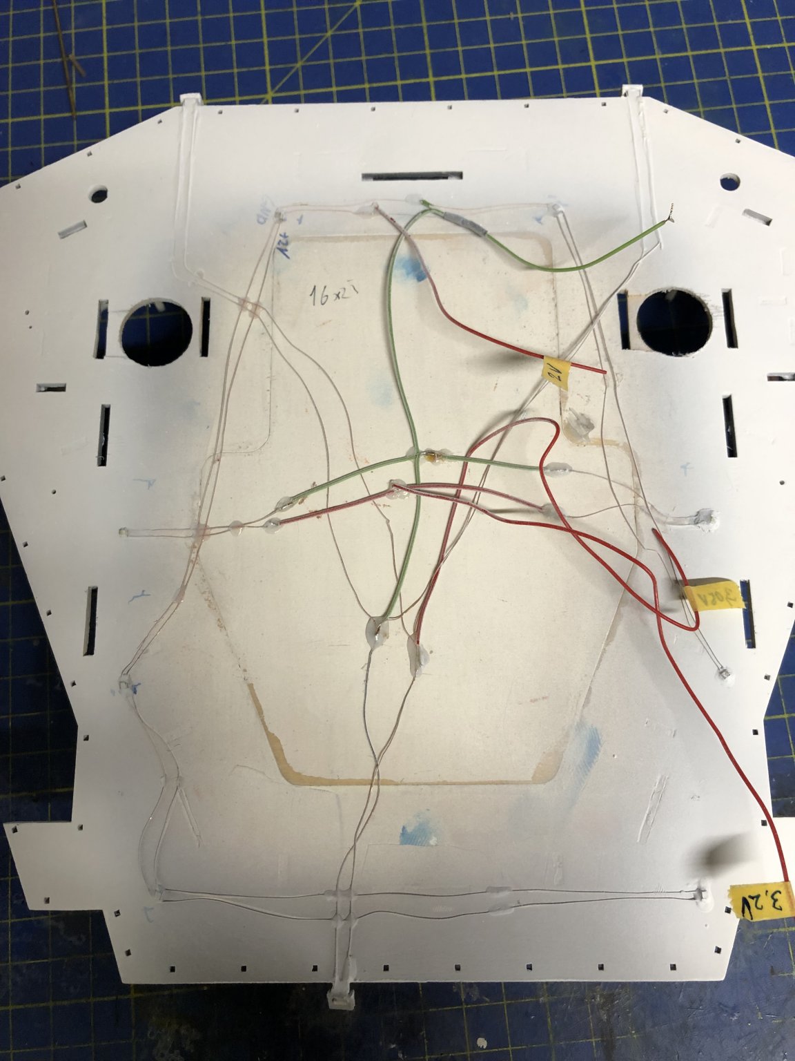
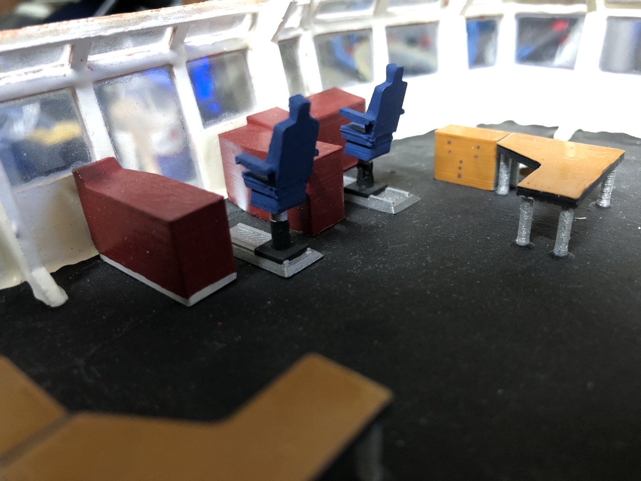
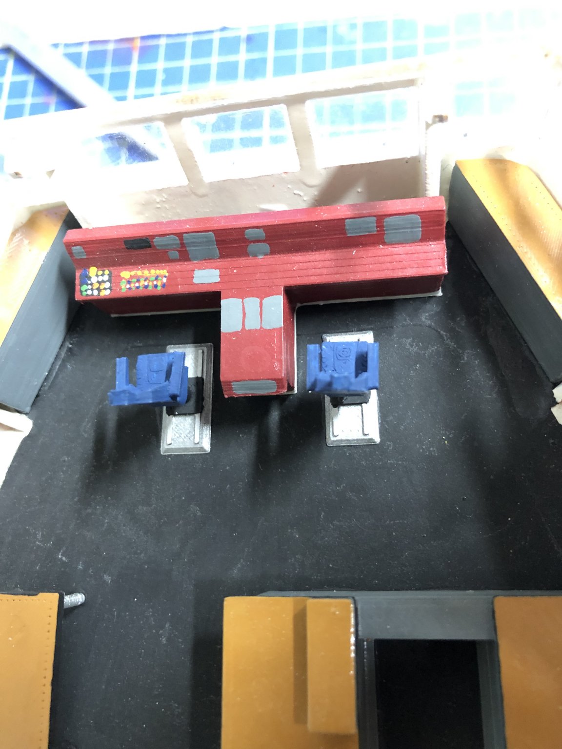
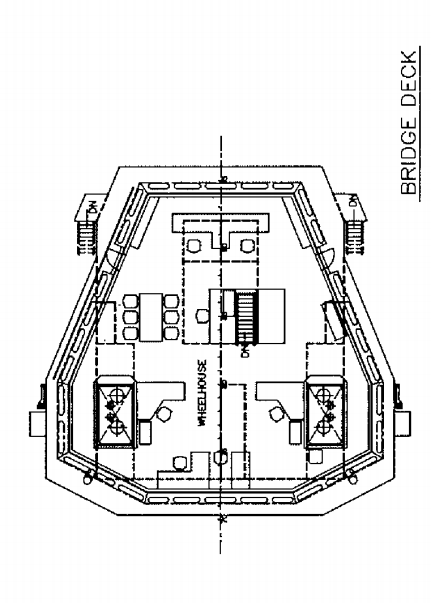
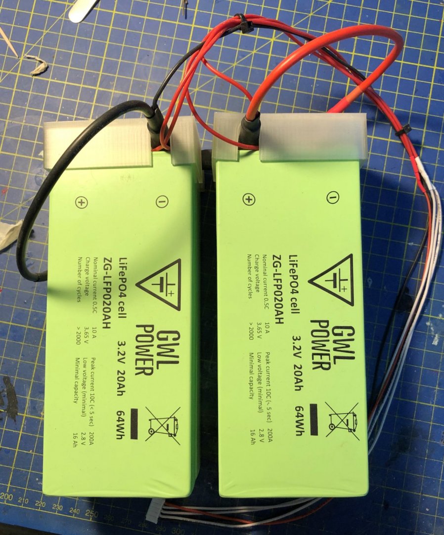
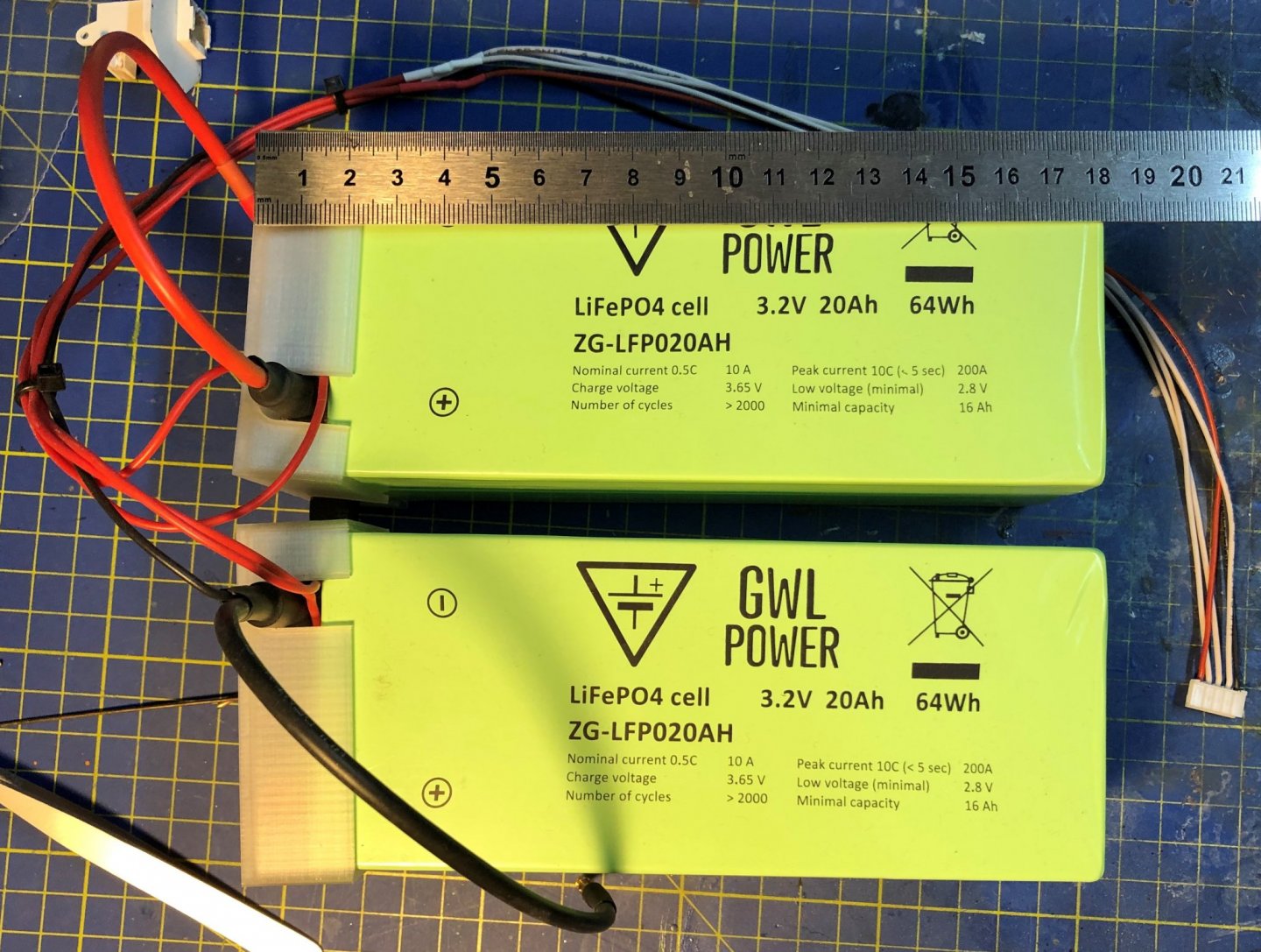
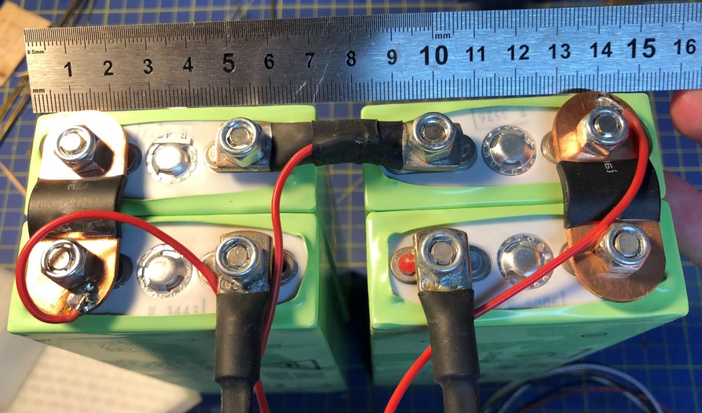
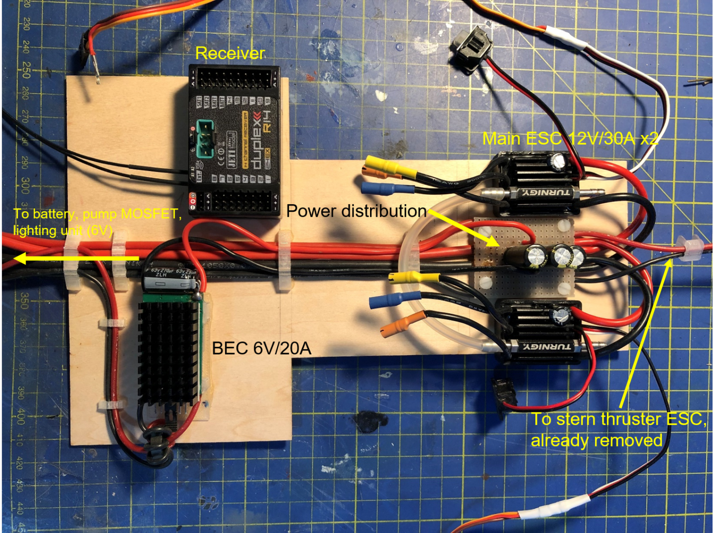
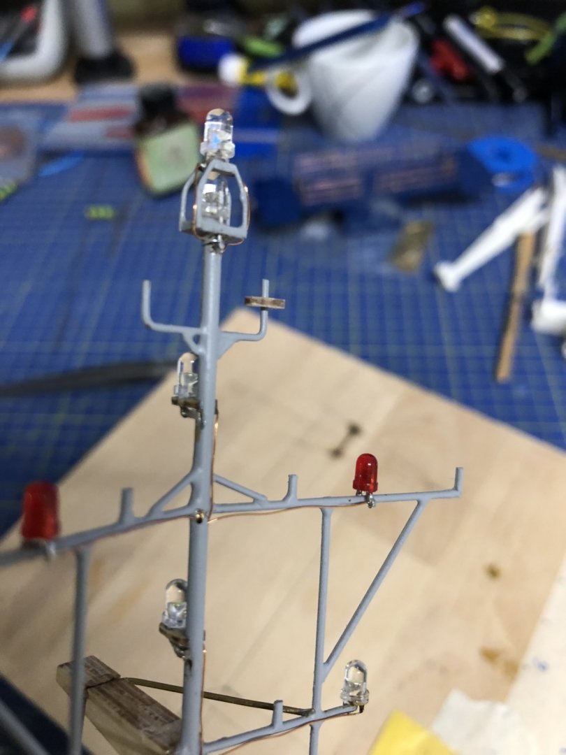
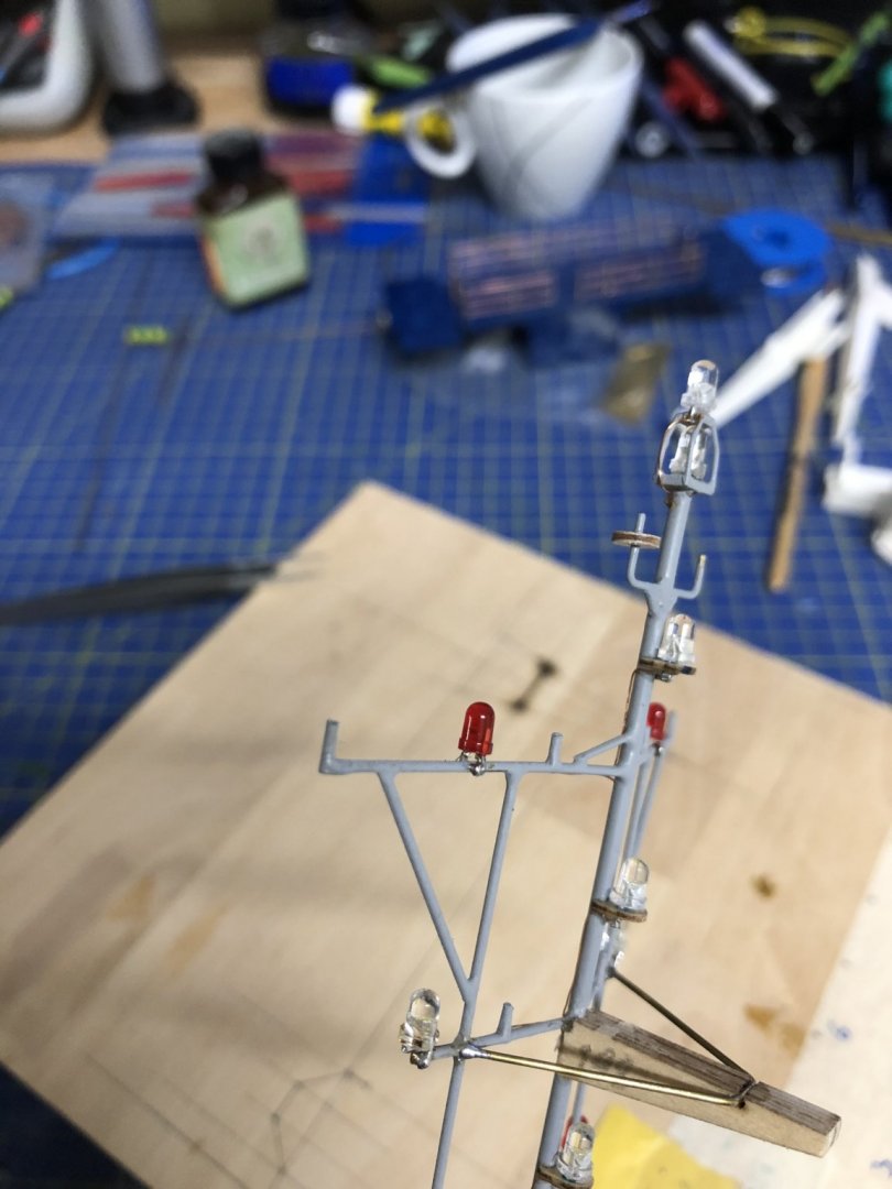
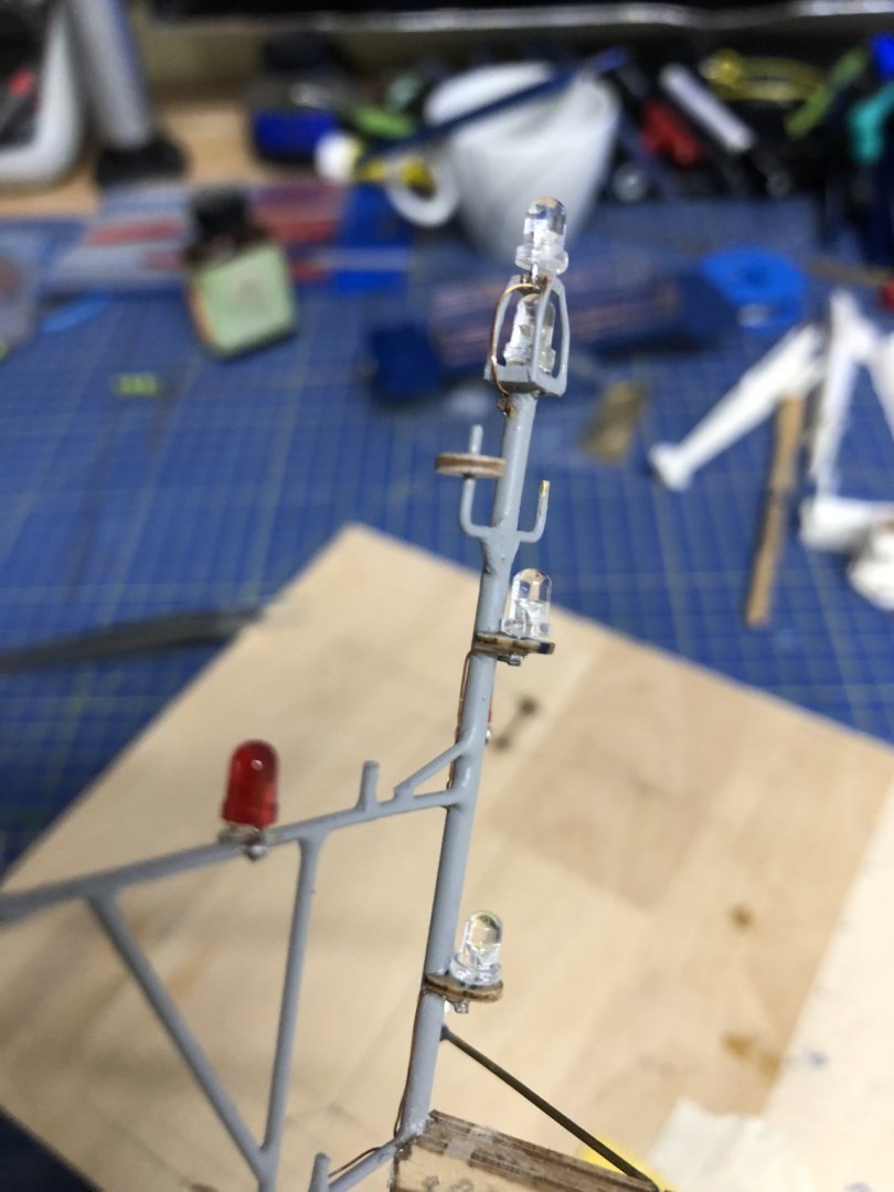
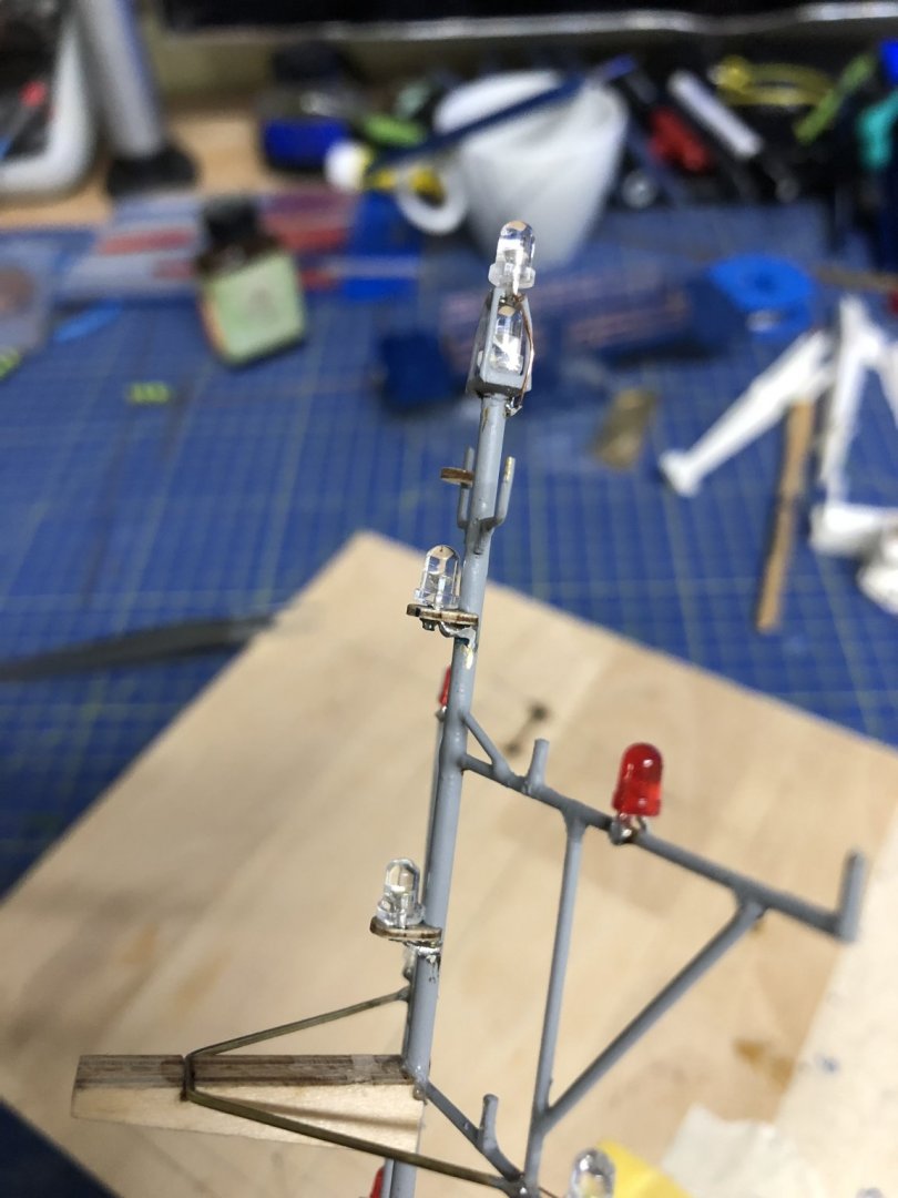
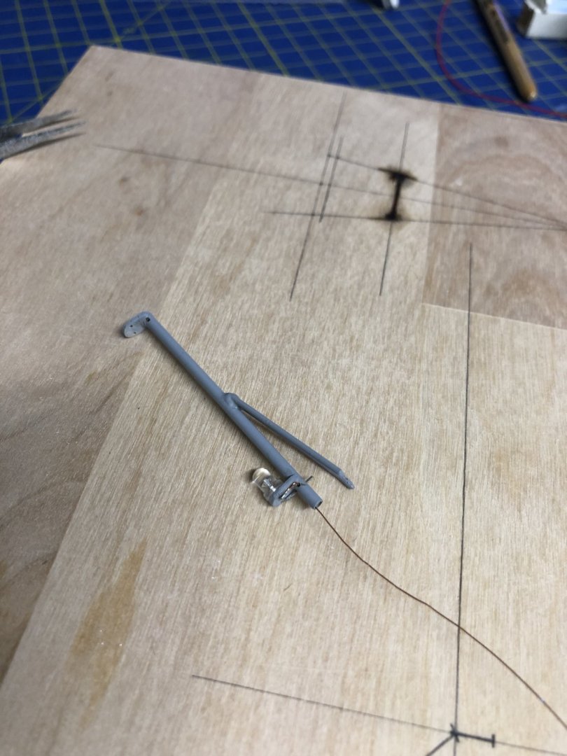
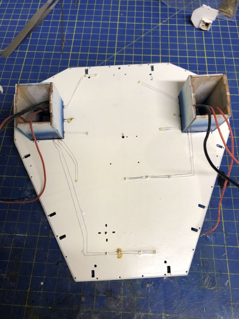
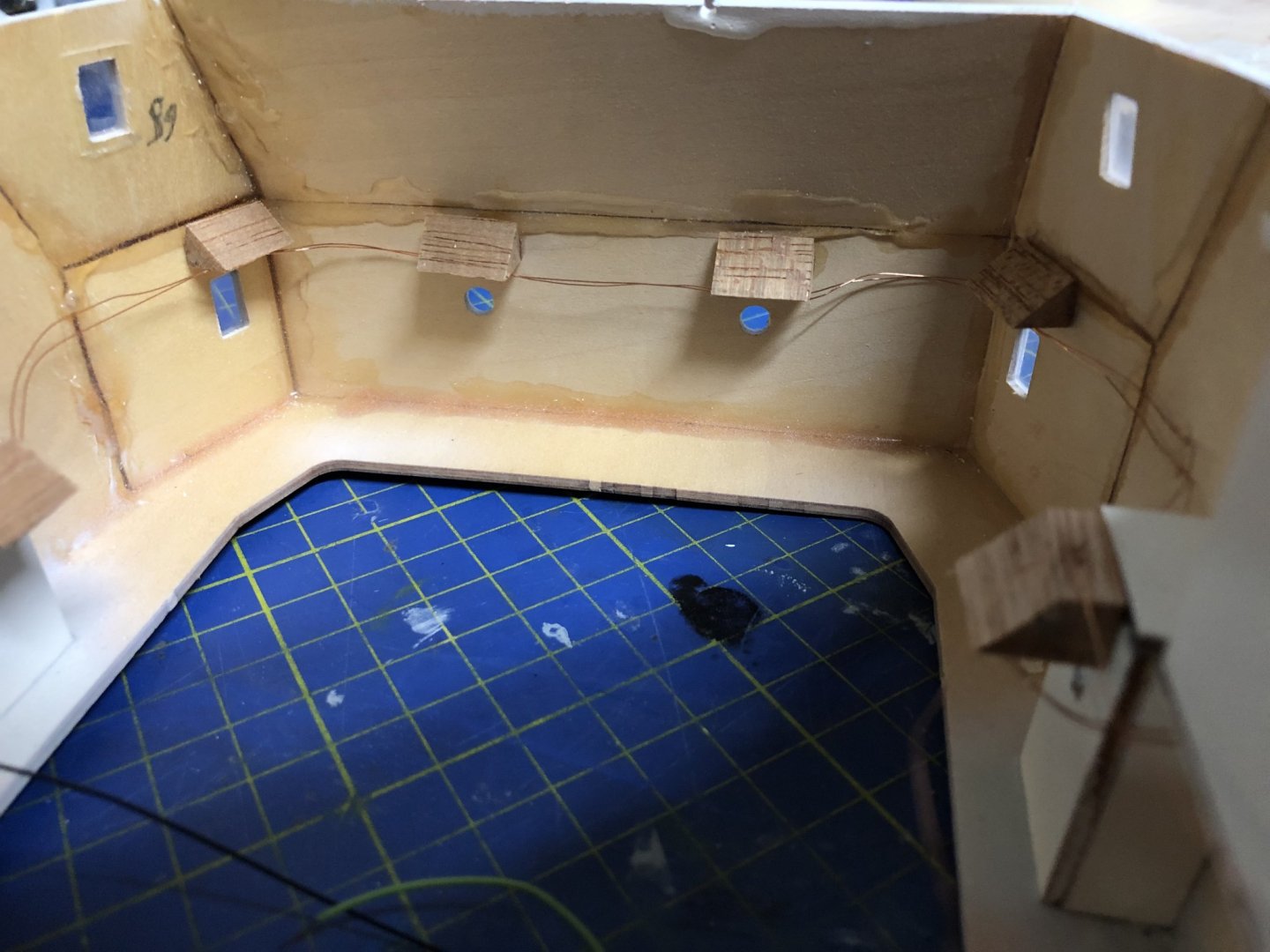
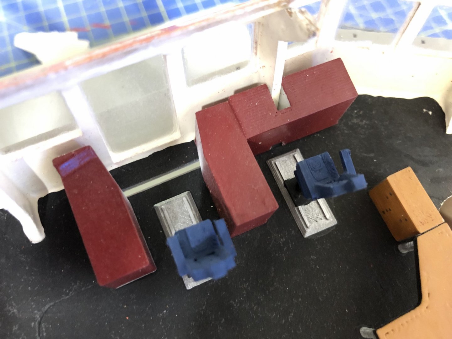
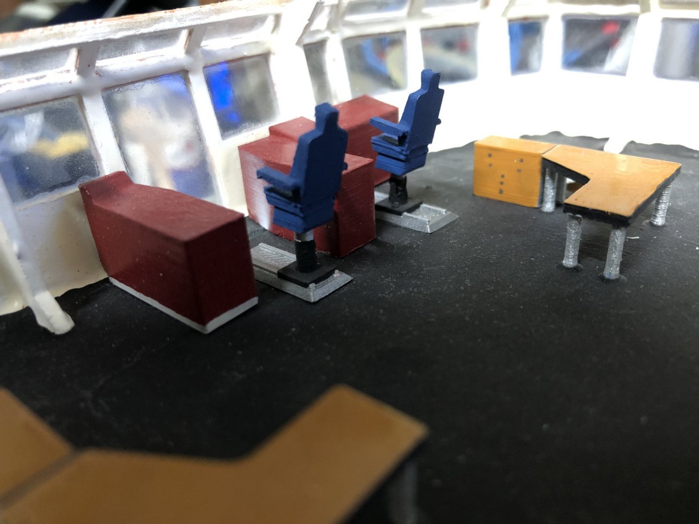
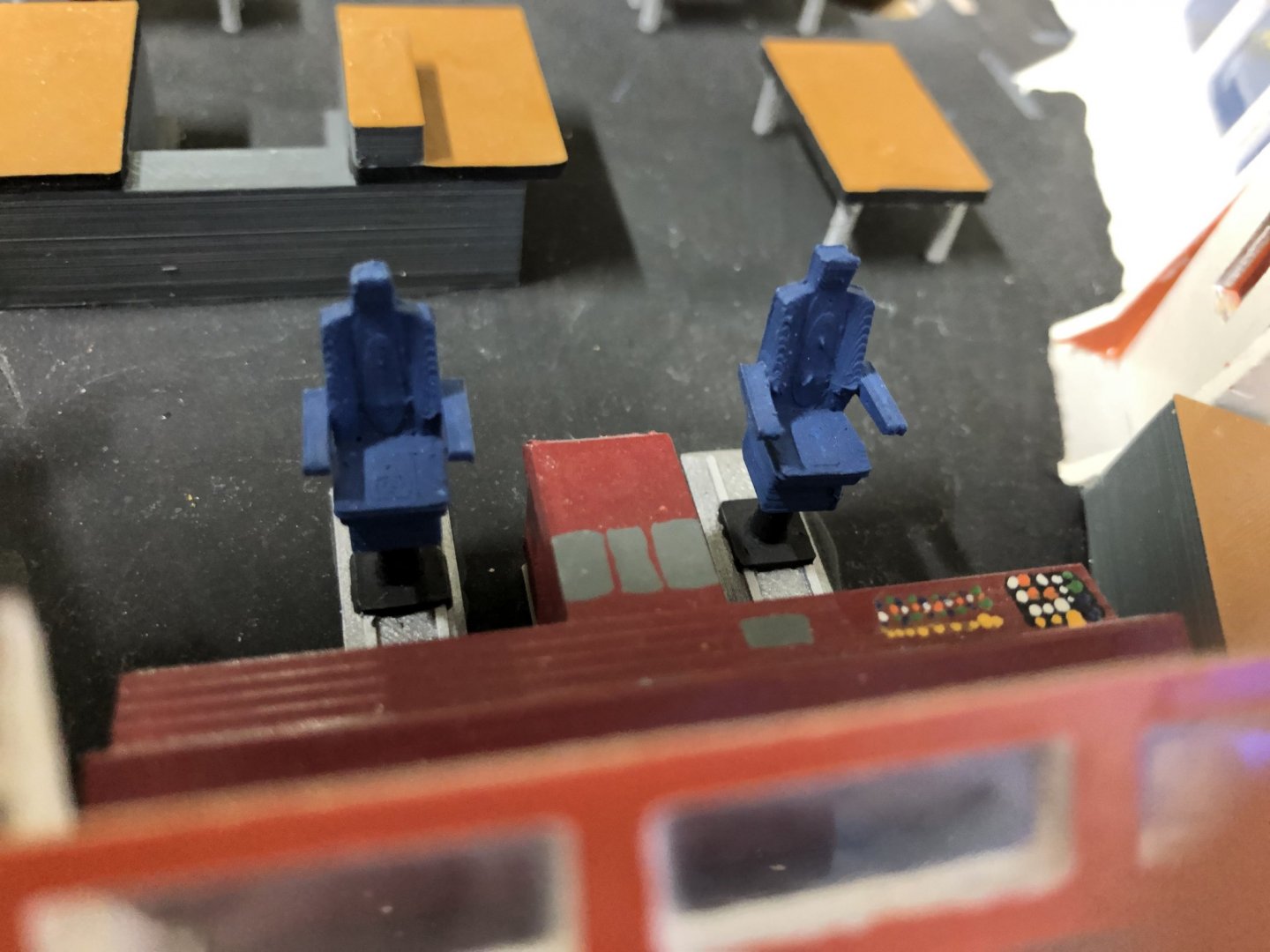
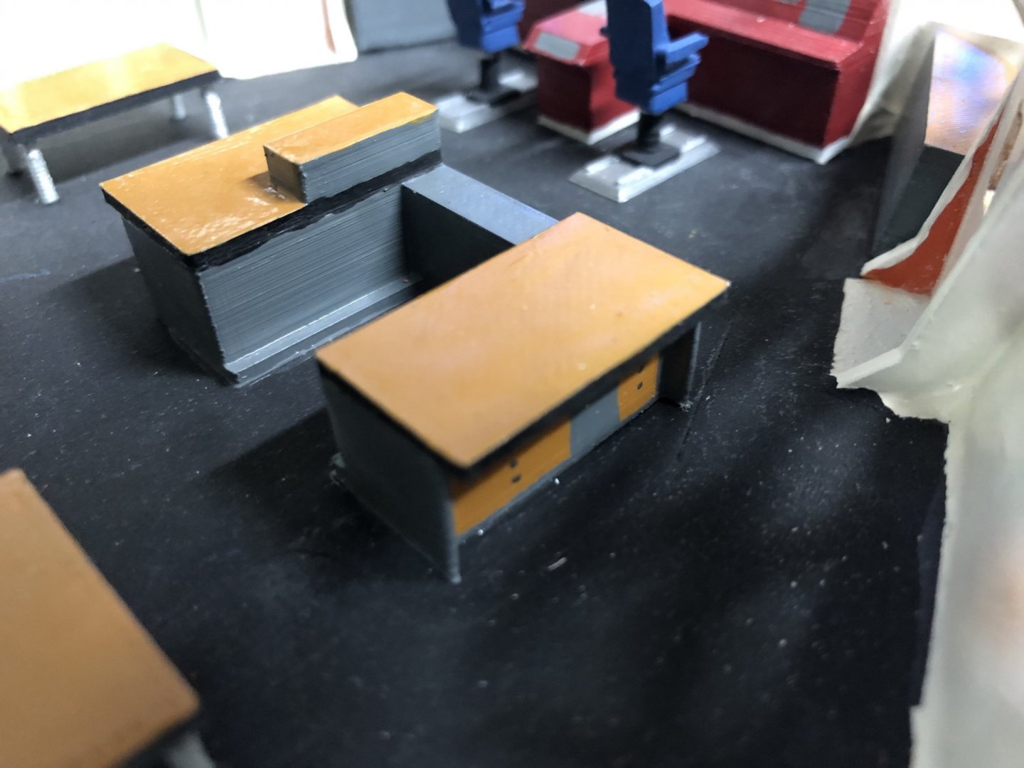
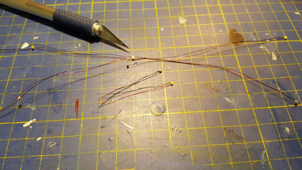
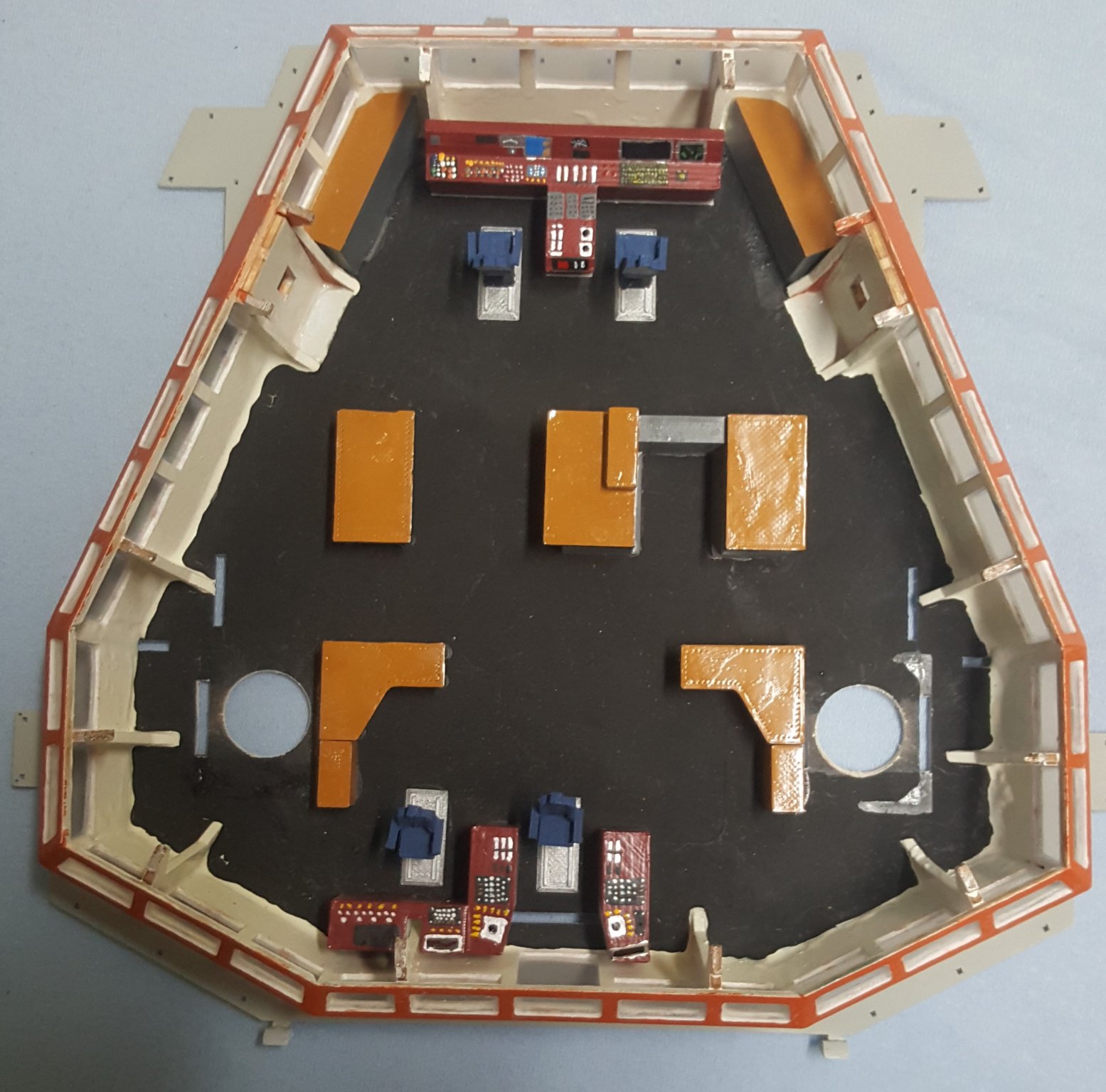
Hello All, Thank you all for the positive response. @Seamanpeter oh thank you for the link, I actually once found that document. And from the deck plan, made out the sizes of the furniture. Here is the general layout of the bridge furniture, also to compare with the real thing. It looks more or less similar. Also don't be sorry, I experimented and it didn't work, that happens. Of course I was angry with it, even stopped the build for some time, but in the end I got back to it, with more motivation, and more knowledge for the next project. Now for todays issue of getting up to speed. As mentioned yesterday, I will discuss some electronics and soldering related building topics. So first lets start with the batteries. For this model I opted for LiFePO4 batteries, because of their smaller size and much lower mass compared to lead-acid batteries with similar capacity. I went with 4 cells in series, so 4S battery, each cell is then 20Ah capacity, and standard voltage of 3.2V. I sourced the cells from here: https://www.ev-power.eu/LiFePO4-small-cells/LiFePO4-High-Power-Cell-3-2V-20Ah-Alu-case-CE.html?cur=1 they sell many different cell capacities, and also stock interesting cell types, like Lithium Titanate cells. Which I would like to try out in some future project, hopefully an IJN destroyer Yukikaze. The final battery pack is on following pictures. the pictures also indicate the overall dimensions of the battery. The cells are interconnected with terminal connectors, provided from the same site. Specific, for this cell are the: Terminal Connectors for ZG-LFP20AH. The cable connectors, and the bridge between the two parts of the pack are made from a standard copper wire screw connectors, don't know the exact term. The wires are soldered in. The 3 red wires coming form the individual cells are for balancing connector. The covers are made to be just push in at the moment, as the pack has to be split into the two sections, for it to fit through the hull opening. They are again made from PLA on 3D printer, later I will probably change them for ones made of PETG, for better water resistance. The overall weight of the battery is around 3kg, I will include the exact figure in a later post. Now Because of the new bow thrusters I will add a small LiPo 2S/7.2V battery pack to power them. I will use one from my other models. later, when the 12V motor variant for the front thruster is available, I will probably swap to that, so I don't need multiple batteries to run the thing. And the motor swap should be relatively easy to do. Next lets look on the power distribution in the model. For this I made a sort of distribution board in the area of the main ESC's. To explain what is this mess. The bow of the ship is located to the left of the plywood deck. From the battery there are two 4mm2 - 12AWG wires leading to the power board, here are two Hitano lowESR 2200uF/25V and one Hitano lowESR 470uF/25V capacitors. I am of the mind, that there is never too many capacitors, also it kinda looks cool. Form this PCB there are leads, going to the BEC unit and water pump in the bow. BEC is a voltage regulator, in my case it will supply 6V, 20A max, to be used by the lighting unit, to be designed and build in the future. Above the BEC is the receiver i use Jeti Model products for my other models (exept cars), so I went with the Jeti Duplex R14 EX reciever, so 14 channel model, should be more then enough. The water pump is driven by one MOSFET transistor located in the bow, this transistor will by switched also by the lighting unit. This picture still shows power leads leading to the stern where the stern thruster ESC was located, these were removed yesterday, because of the different voltage run on the new one. Lets look on the lights. For the reference on the light signs I referenced to Naval law and my Skipper course materials, section on ship light signals, basically Naval Law, but condensed, and with pictures in text, rather then on separate web page. But for reference here is an US web site: https://www.navcen.uscg.gov/?pageName=NavRulesAmalgamated#Sidelights, just I couldn't find the case for this specific tub, when the towing vessel is greater then 50 meters in length and the towed assembly exceeds the overall lenght of 200 meters. Which should lead to increase in the number of masthead lights to 4 lights in a vertical line. Or at least that is what I learned, and presumably how the Ship was configured when built, since on a picture of the mast there were 5 lights, where I presume the 5th light was an anchor light. So without further adieu here is the main and mizzen mast. Both masts are made by soldering of brass tube for the central part, and brass wire for the sides. Yes the main mast looks like a Christmas tree, when all the LEDs are lit. The mizzen mast is still missing the yellow LED above the white, because of mix-up of order parts I got instead of 5 yellow LEDs 11 relatively expensive capacitors and I didn't have the need to place an order on 5 LEDs by 25 Cents each with additional 5 Euro shipping, so for now no yellow LED present. Subsequently all the white LEDs will be matted with sand paper, to provide more homogeneous light diffusion. And the adequate sides of the LED will be painted silver under black, to create the sector light effect. Regarding the powering, all of the LEDs are connected to the mast for the Ground terminal, the mast is then contacted at the base. The positives of the LEDs are then routed using 0.4mm Dia. enameled wire copper wire through the center tube. Some details of the LED installation follows, the last picture then shows the bottom part of the mast. Last for today I will write about the interior lighting. I went with SMD LEDs for this, as they are easier to fix on a flat surface. However this posed significant challenge, as they are small, very small and therefore very susceptible to damage during soldering. I went with a mix of cold white and yellow/warm white, presumably only to complicate the thing even more, since the cold white ones would be perfectly fine all around. Here I present the bridge lighting to the left, and the "cabins" and staircases on the lower deck. The brown spots the the bright ceiling are spots, where I had to replace the LEDs after I already glued the LED stripes to the part, newer skip testing. The 3 flood lights are made of SMD LEDs as well, but using ones with much higher luminous intensity (the value measured in candela). For the other decks, the lights are mounted inside the superstructure. In the next issue I will continue on the topic of soldering, specifically how I dodged the bullet of soldering aluminium because of the supplied handrail stanchions. Cheers George
.thumb.jpg.8f7e31c4707ae711ba63be6f16289b12.jpg)


- 90 replies
-
- 4
-
-
- fairmount alpine
- billing boats
- (and 1 more)
-
Hey Peter, From my experience with my "stock" build so to speak, the displacement of the model should be around 10 to 15 kg I believe closer to the 10 kg figure. At least for the stern a ~2 kg hammer resting of the deck was enough to get the propps fully submerged, then the bow was almost entirely out of the wafer. So don't quote me exactly on the displacement. If I manage, to get the thusters for my repairs today, and mount them in the weekend, I may get you the actual displacement figure during the Sunday, if not, then maybe next week. Oh and regarding the propulsion system, maybe you don't know but there is a German company making these belt driven ones, here is a link: https://www.bauer-modelle.com/epages/Bauer_Uwe46269592.sf/de_DE/?ObjectPath=/Shops/Bauer_Uwe46269592/Categories/"Schiffsantriebe%2C Spezial- und Wellenantriebe"/"Schottel%2C Z-Antriebe" They are quite expensive to my taste, but they look to be superb build quality... Regards George
- 35 replies
-
- 1
-
-
- fairmount alpine
- billing boats
- (and 1 more)
-
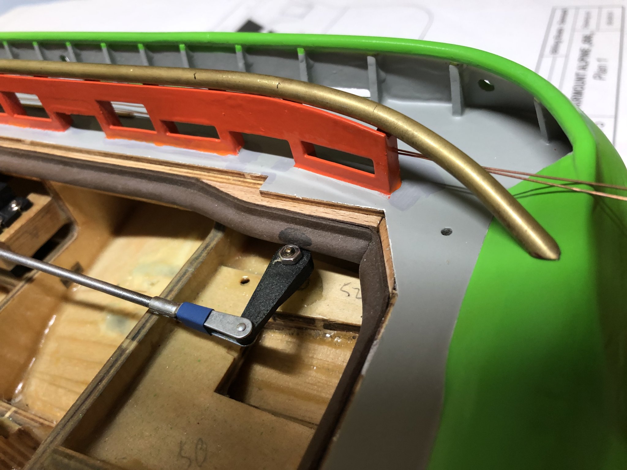
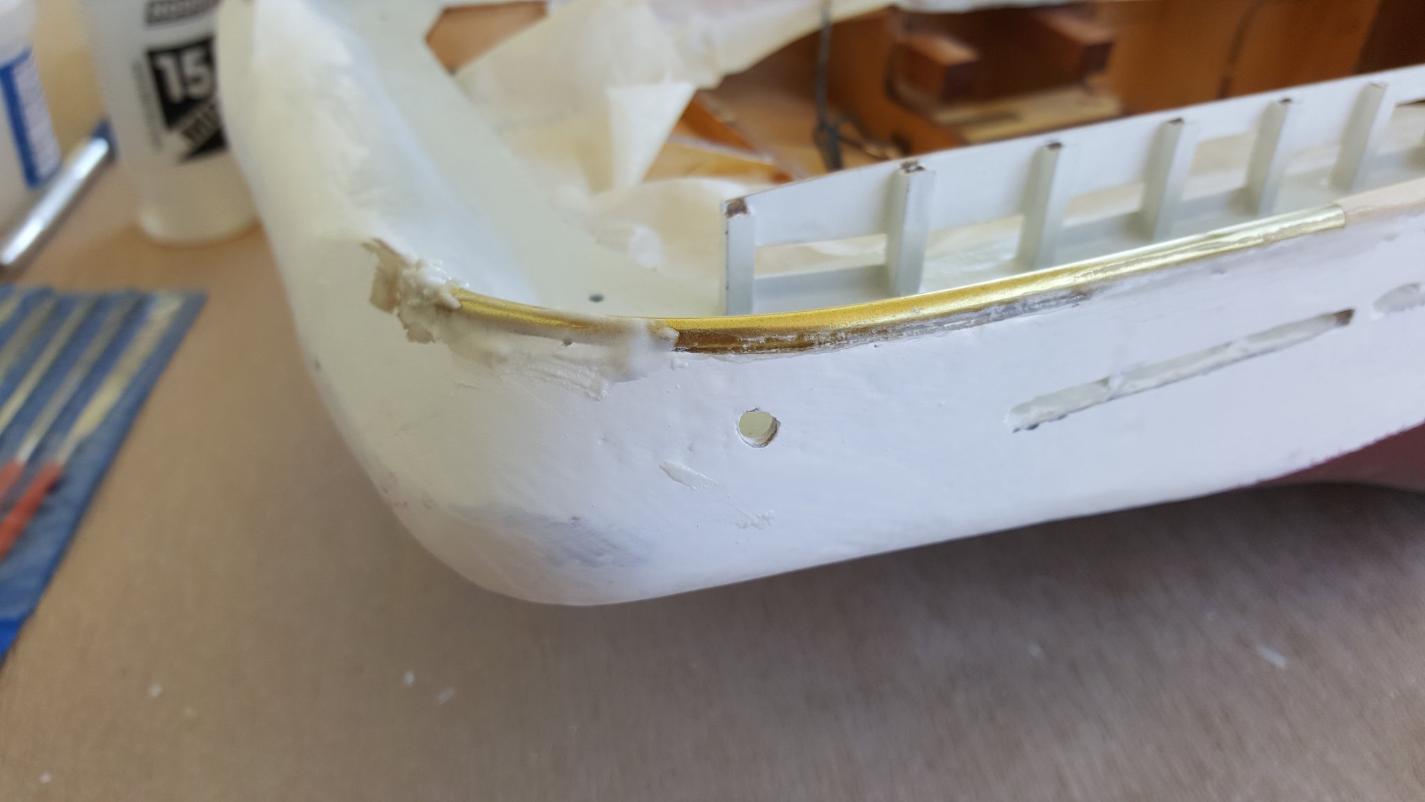
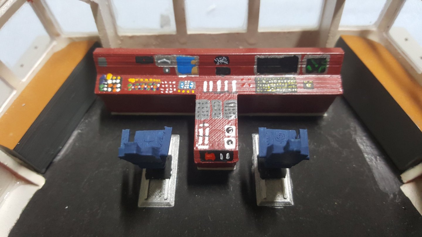
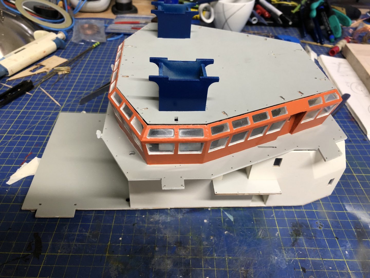
Hello All, So let me try to get the build log up to speed, with the actual build progress. For information, all paint numbers written are from Tamiya paint line. First, lets start with the hull and the bridge superstructure. The first picture shows the paint job on the lower section of the hull, here in detail the starboard rubber and nozzle detail. I tried to create some shading in the colour by fist painting with black LP-1 and Italian red LP-21 with the use of airbrush. The nozzle is still missing the pint of the electrodes, to be done in flat aluminium XF-16. More details on this paint job will follow once i finish the rebuild of both of the thrusters, as now I don't want to turn the hull because of all of the debris that sits in the thurster areas after the sawing. The second picture shows the dry-fitted superstructure. The windows were done form the supplied clear plastic sheet, and glued to place with the BSI Super-Gold+ odorless CA glue (this is my CA of choice, for gluing basically everything that does not require high structural rigidity). The second set of pictures shows details of the safety railing, if that is the proper name for it. With the bottom part being painted and the top part recently finished form the supplied 5mm dowel and additionally 5mm brass tube for the compound bend in the stern portion. Here one can see my choice for water tightening this part of the hull. I used the window sealing foam on the hull and the deck has an Aluminium L profile with smoothened edges glued to the underside. Next i will dine into the bridge itself. As I managed to find a picture of the bridge on one German website. I went and designed the pieces in CAD software and printed them out in PLA with the layer thickness of 0.1mm. The stern helm still needs to have some paint "controls" added. Now for the most recent work, the rebuild of both thrusters. The new ones are, I believe, the industry standard Raboesch ones. For the Bow I ordered one middle-large bow thruster, the one with the 22mm padle housing. For the stern i ordered the mini bow thruster, because of the space confinement. For this it was necessary to first somehow remove the installed ones, I wanted to do this with as little damage to the hull as possible. So for the stern, where there is good access for drills I drilled out/broke-off the original one, with more modifications coming, as I get the thruster itself, so I can make the final adjustments. In the front the situation is more complicated as there really is no space for power tools, even with my Proxxon it was difficult to get there effectively. So the only option was manual labor with metal saw, for better efficiency I cut off the end of the blade under 45 Deg. to get longer stroke. The end result is on the picture to the right. Now the rest is to chisel out the plywood keel, on which the piece holds. In next post I will describe some parts of the mast and electronic equipment that I chose.

- 90 replies
-
- 5
-
-
- fairmount alpine
- billing boats
- (and 1 more)
-
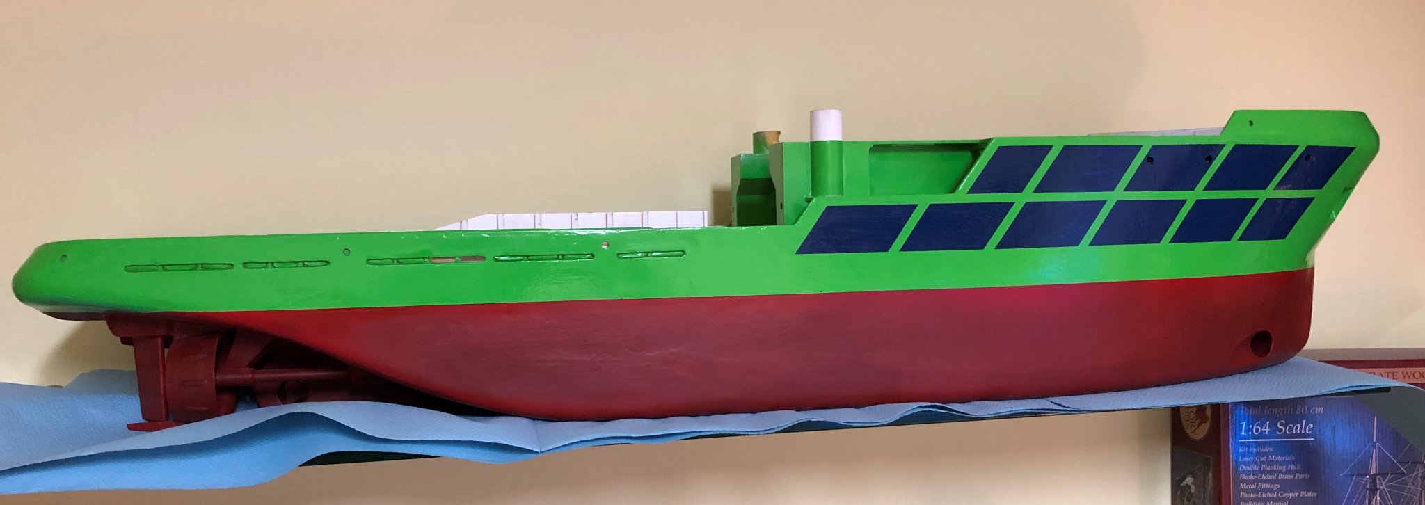
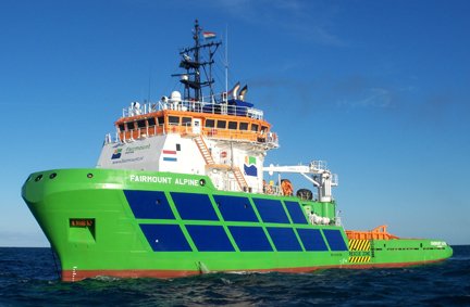
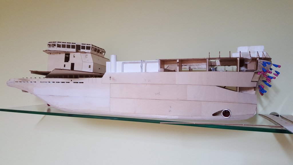
Hello All, I apologize for not posting on the build for so long. There were two reasons, first I always forget to take pictures of the process. And second I finished university, started a job and therefore had to adjust my routines, which took some time. also I met a colleague who owns and is renovating a historic sail boat, so I invest some time there recently as well. But enough with the exuses ,back on topic. In the following posts I will try to catch up to speed with the build here and try to do regular updates of the build log. Now for the questions posted: @Seamanpeter The hull was more or less "seaworthy" so to speak, fully painted form the outside and ready for the details. Then on one of the two trial sails, I found out that the thrusters of home production had super low efficiency and I even managed to burn one of the motors during testing. This also caused me to put the build on hold for a good 6 months. This last weekend I started again, by surgically removing both of the thrusters installed form the hull. This is still ongoing effort. So now it is more like a submarine, than a floating vessel. @FoxtrotHotel No the winch at the moment doesn't have any end-stops, maybe in a future update. The latest version v1.2 (pictures will be posted in following days) is printed on a 3D printer, that I own. I was thinking of putting some end-stops on the winch, but didn't come up with a reliable way of doing it. But it can be easily taken out of the finished hull so, I will be experimenting with it once the model is finished. In the end let me post some pictures I found on my phone of the builds relatively current state. This image shows the detail on the stern, here the entire length on the railing has a 5mm dia. wooden rod, that is meant to be bend to plance on the stern, which I found to be literally impossible to do. The solution brass tube with 5mm OD and ~0.5mm wall thickness. just for info the white putty like stuff is epoxy mixed with micro air balloons, something of this sort: https://www.lindinger.at/en/supplies-und-misc/building-materials/pore-fillers-und-putties/rg-micro-balloons-ul-250ml-can I will have to find the tin with the rest, to determine the exact type, also i quite need it for the next steps.... The picture shows the model how it was till last weekend, mostly painted. In the end I used Tamiya Paints for everything. For the underwater section I went with the Dull Red paint (TS-33 or LP-18) with som accents made by Italian red LP-21 and black LP-1 done by airbrush. before the main paint coat. I will include some details on the results in later post. The top part of the hull is painted with Tamiya TS-22 light green. Which to me looks relatively spot on. However I had hoped for it to be the same shade as the X-15 light green, in the end there is slight diference in the colour. To me this is negligible difference, I will include a picture of this difference. The blue is then the standard TS-15 blue. For the colour picking I mainly use this picture: Unfortunately I picked the wrong orange (Tamiya TS-15 in hopes it is the same as the X-6 which would be perfect shade, at least to me), so mine is too red. But since the cockpit has all of the glass work done it is just easier to continue with the wrong shade, then to try and mask everything of and repaint it, I think. However it would certainly look better with different orange. I have also see the same problem on many other models, that I found on the internet. Best Regards to everyone still interested in the build. I will try to keep posted this time around. George


- 90 replies
-
- 6
-
-
- fairmount alpine
- billing boats
- (and 1 more)
-
Making of Christmas tree Since the model is sufficiently large enough, I will be fitting most of the lights with LED's. I started by the windows (not shure of the correct name for these) that are at the bow. For this I used SMD LED's for their ease of mounting, but not of soldering. I made two stripes with 3 LED's each for either side, I also made a pair of LED's for mid-deck lights. The SMD LED's are really small, and the used enameled copper wire is of miniature dimension, the diameter is approximately 0.35 mm. This picture shows the position of the mid-deck LED position, this LED will have to be mount before the bull is finished, because later it will be hard to get it's position right.
- 90 replies
-
- 4
-
-
- fairmount alpine
- billing boats
- (and 1 more)
-
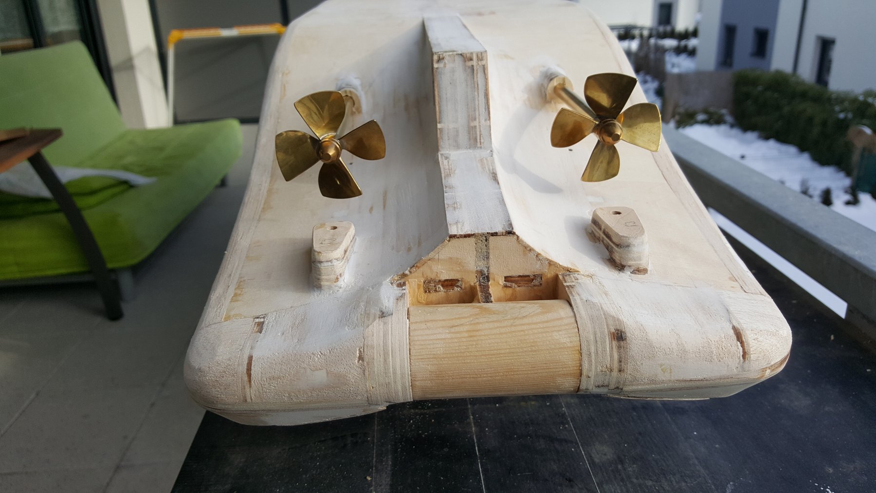
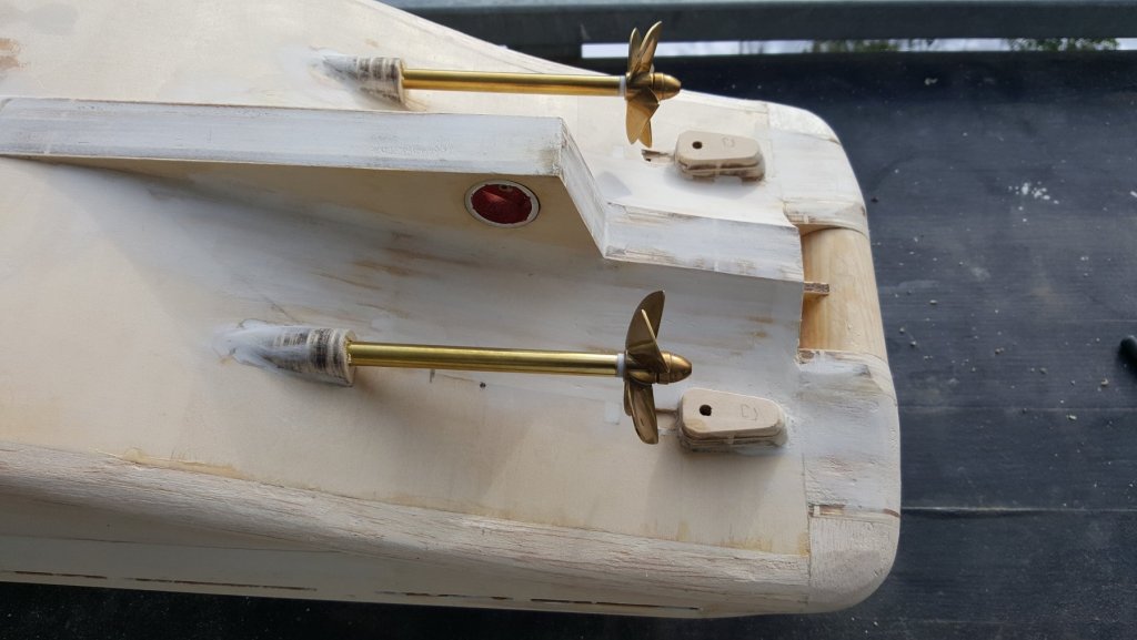
Since the hull is near being completely planked, I went and bought a set of new prop shafts with covers. I did this for multiple reasons, first, the supplied ones used brass friction bearings on both ends, they seemed to be of quite good quality, but better be safe, then to have to drill out a leaky prop shaft of a finished ship. The new ones have a pair of brass-graphite bearing. Second, the supplied ones were using a thin walled brass tubes as their covers. This poses a thread of an easy bend for example during transport. And lastly, the new ones have an engine mount, to which the engines are screwed, ensuring their squareness. Some pictures of the new prop shafts, with propellers, for checking easy movement. Outer view of the new prop shafts test fitted. Stern view, checked if the props are parallel. The propellers are 4 bladed brass dia. 50 mm suitable for nozzles. The inside view of the prop shafts, one can see the engine mounts on the ends.

- 90 replies
-
- 2
-
-
- fairmount alpine
- billing boats
- (and 1 more)
-
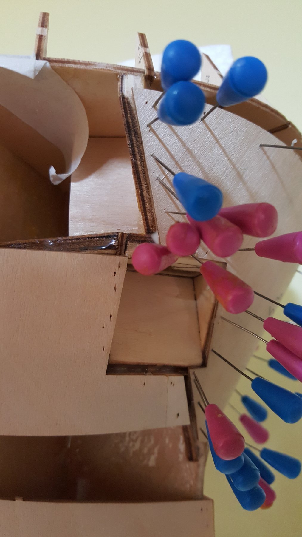
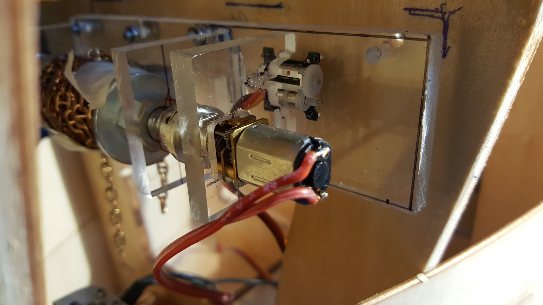
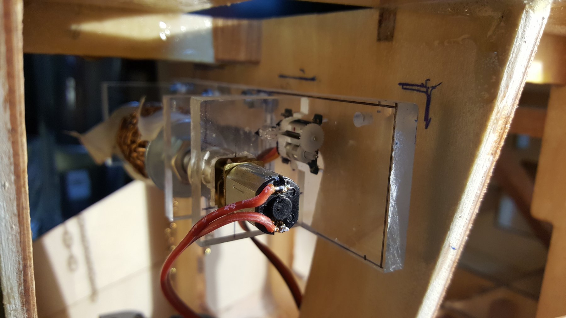
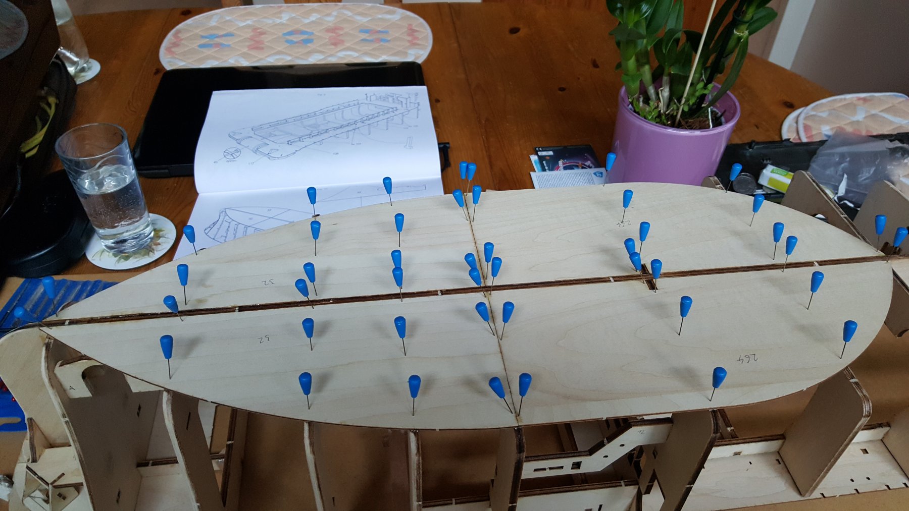
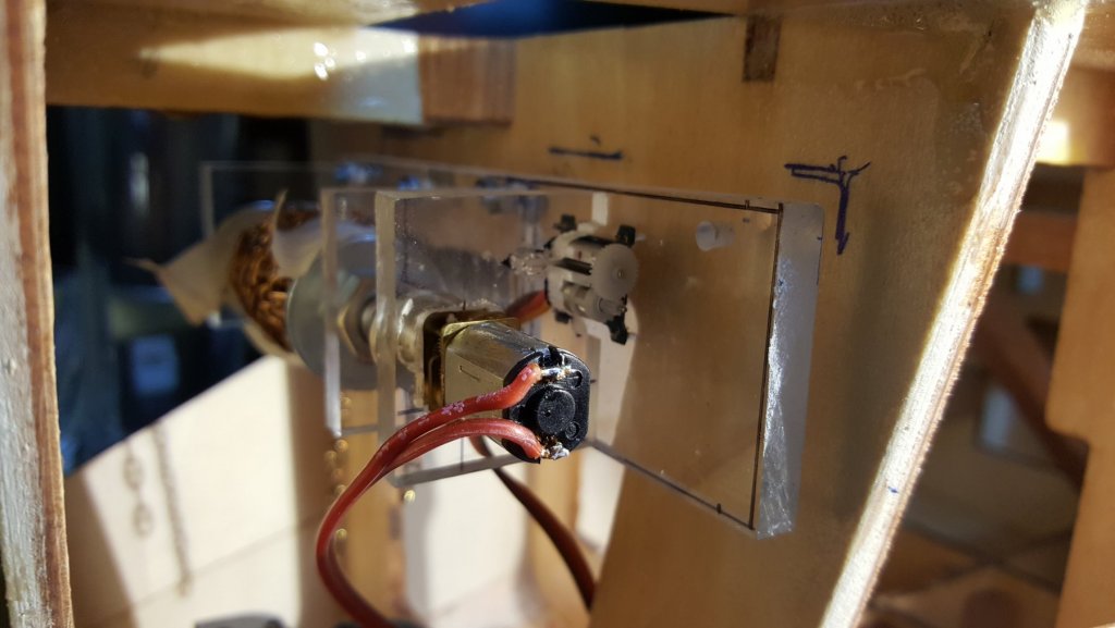
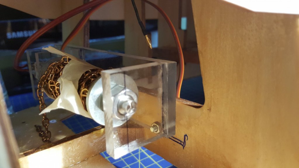
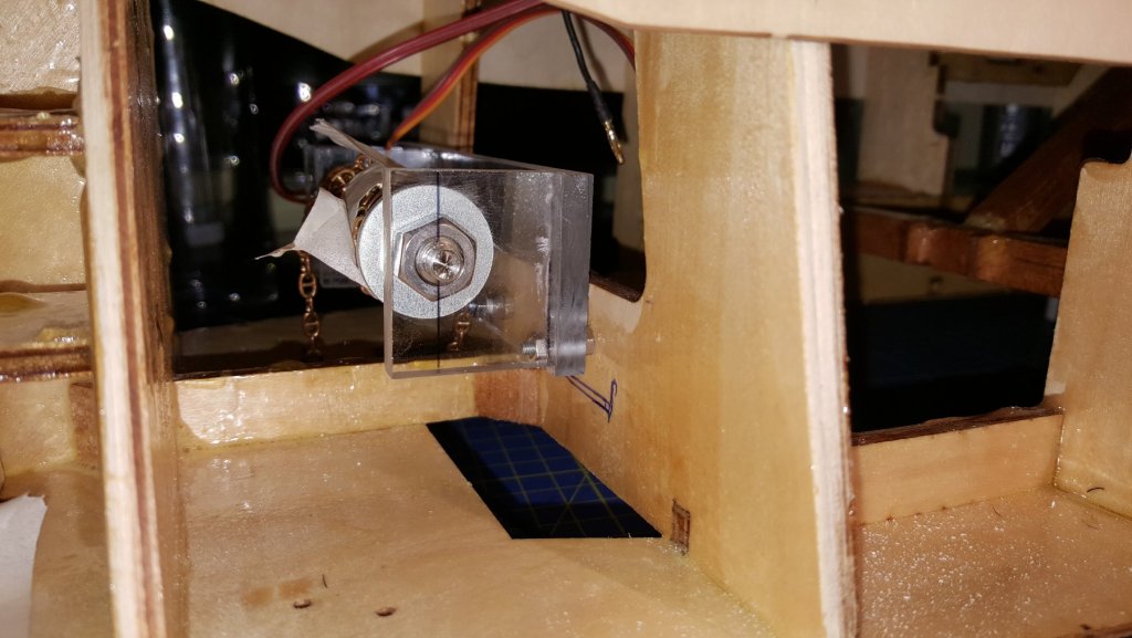
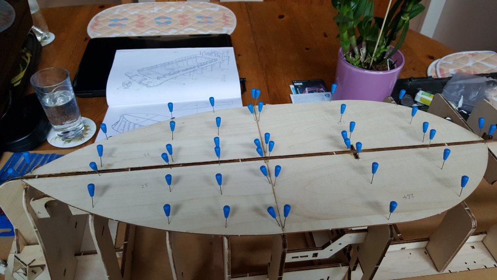
After a long time, I got back to building this model for a while during the winter holidays. During the semester I, from time to time glued some planks, resulting in almost done hull... The almost finished hull planking, here while bluing the first bow piece. The bow planking is made of two pieces glued together to make the rather complicated bend. Here in more detail: Here is a side view of the glued piece, one can see a rather large gap between the two planks (approximately 1 to 2 mm wide), this is a result of incorrect sanding of the bulkheads. Luckily it should be easily filled with some spare wood. The bow view. Lots of modeling pins are needed to hold the piece in place. The piece was first soaked in hot water and bend to the rough shape it needed to be prior to gluing. To finish the planking it is necessary to paint the middle deck area (if this is the correct name of this deck), because the final plank will effectively flock the access to the roof, in this picture in the right corner. I added the anchor winch of my own design to the hull. The main parts are made of 10 mm Plexiglas glued together using CA glue. The axle is made of a stainless M8 rod, the end-pieces are washers between two nuts, secured by blue Locktite. the used engine has a gearbox with ratio 298/1 and 20 000 RPM, resulting in around 67 RPM at the exit drive shaft. The engine is then connected to the axle via a homemade clutch. The "drum" containing the anchor chains, which still need to be blackened somehow. And the placement of the winch in the hull. (there the hull is upside-down due to easier mounting of the winch).


- 90 replies
-
- 3
-
-
- fairmount alpine
- billing boats
- (and 1 more)
-
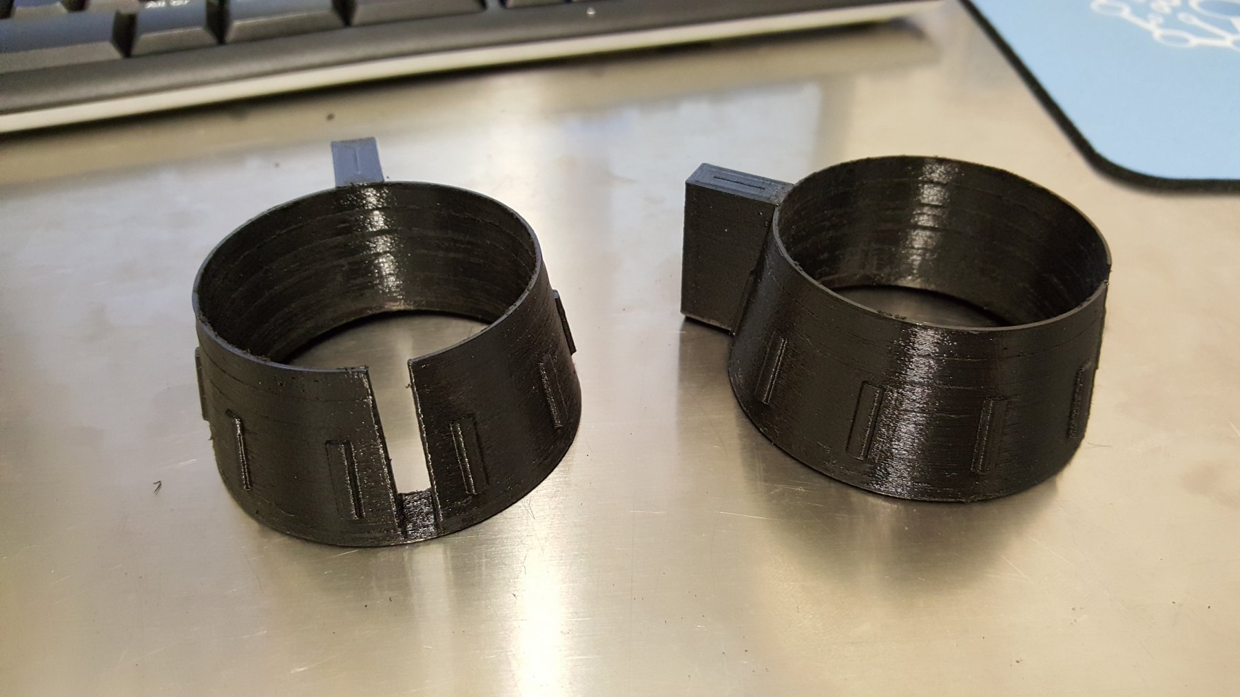
Lately I don't have much time to spend on this project, must work on my diploma thesis. But nevertheless, I was able to do a couple thing, start planking the hull, finish the anchor winch (the pictures for these will follow in the next post/s), and recently in the nights I started to 3D print some practice things. Recently I designed and printed Kort nozzles for this model. I created them using "reference" ictures from google and some basic information from some web-pages. The results are from my perspective quite good and will use them on the build. The inner rounded sections are 51 +/- 0.1 mm in all directions, which is for this application good enough. The bottom slot is for the rudder support. The only thing that is necessary is to polish them and pain them red. George
- 90 replies
-
- 5
-
-
- fairmount alpine
- billing boats
- (and 1 more)
-
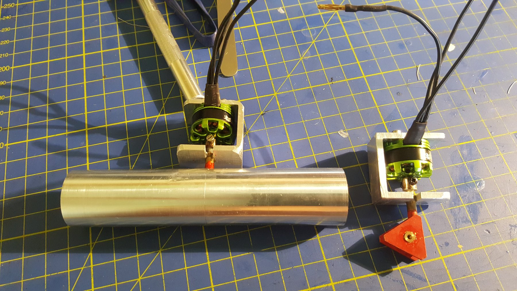
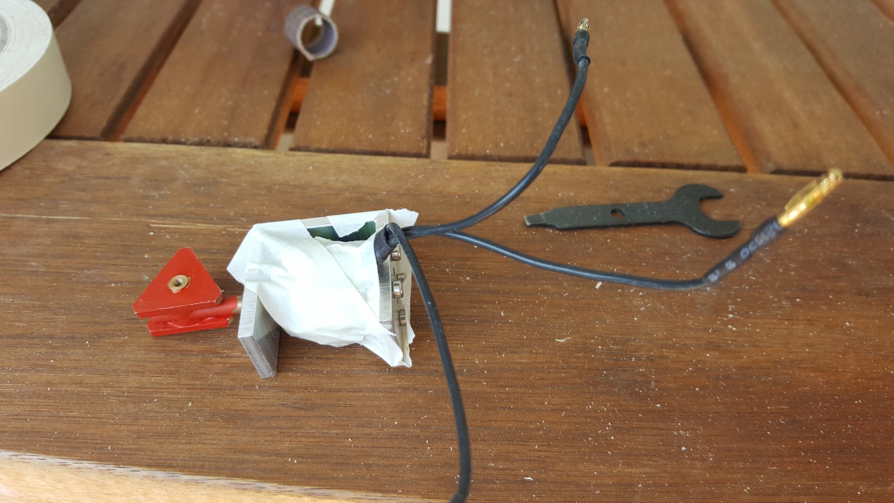
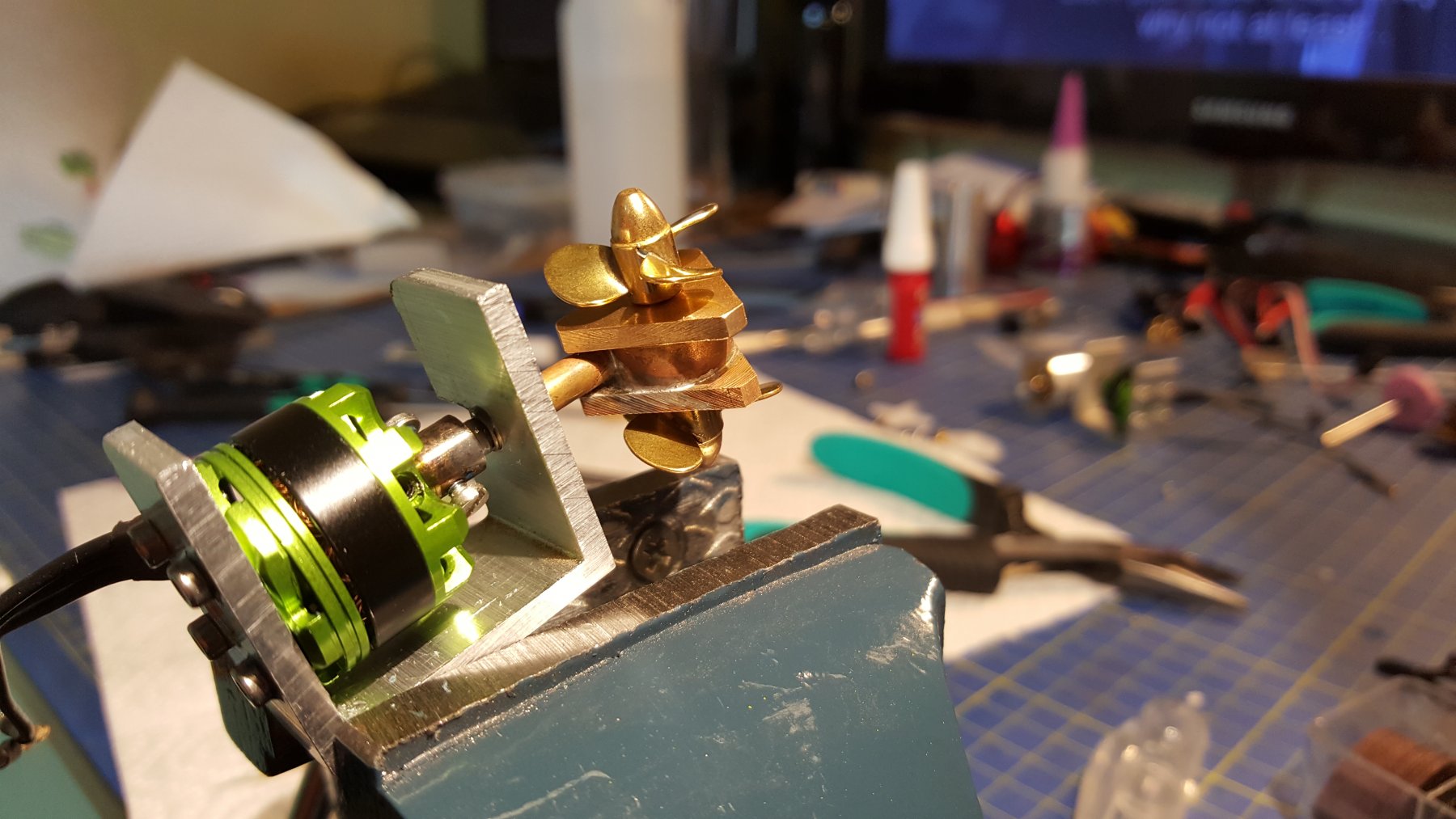
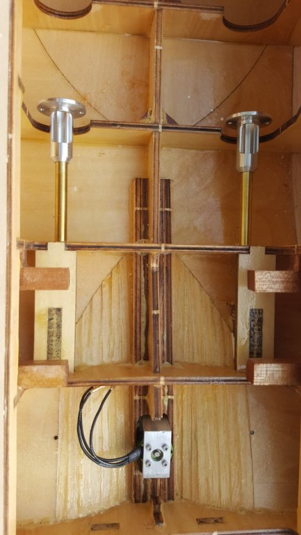
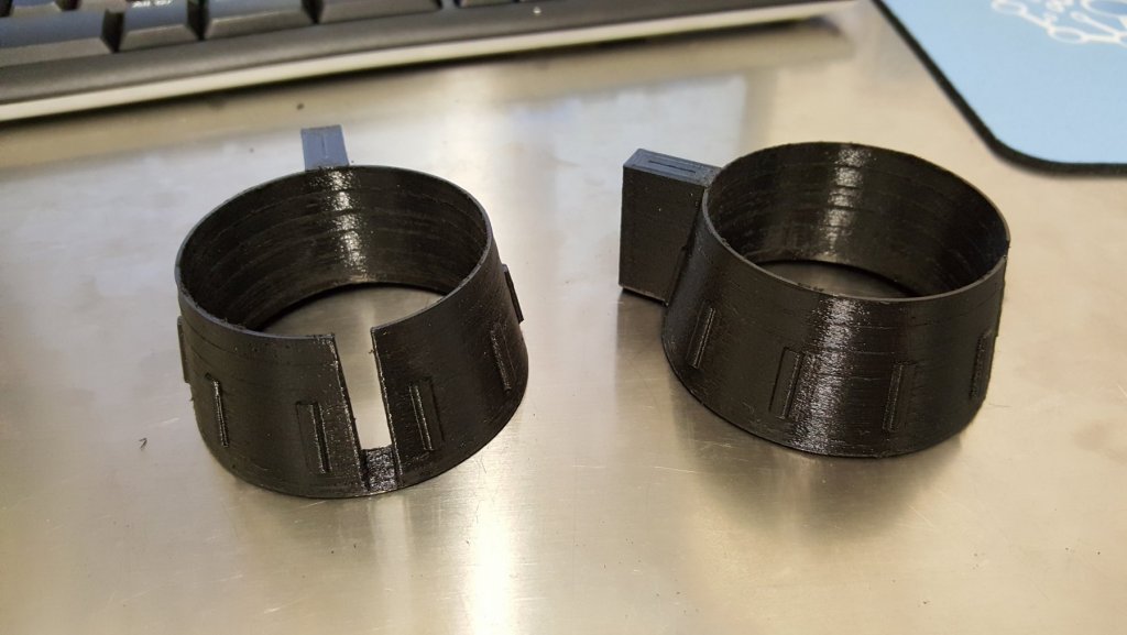
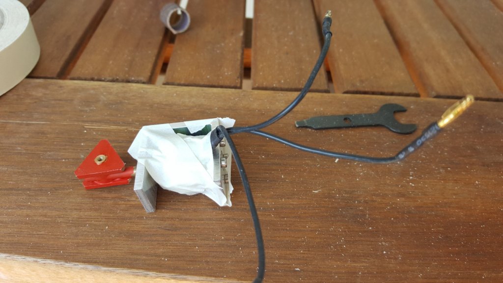
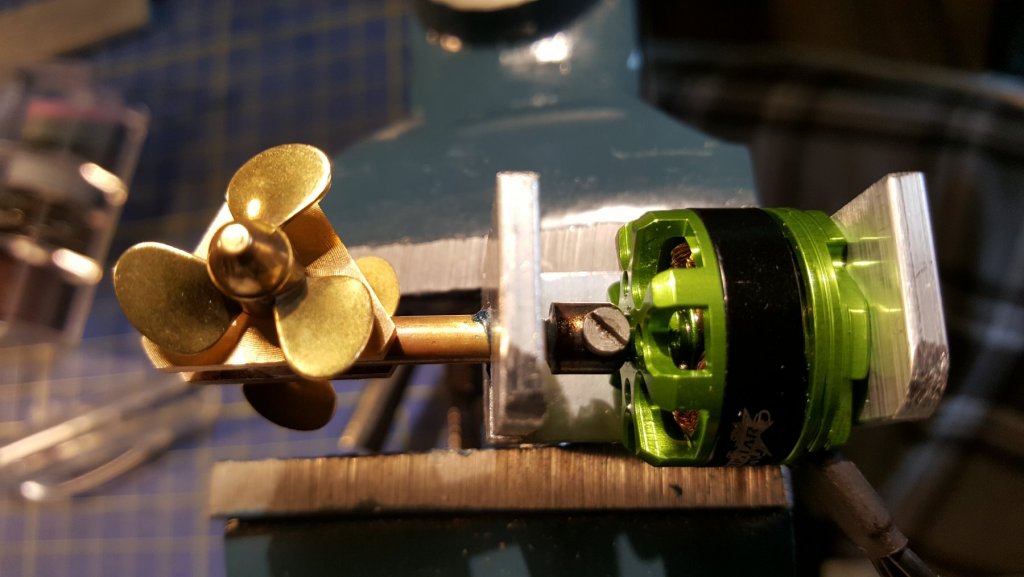
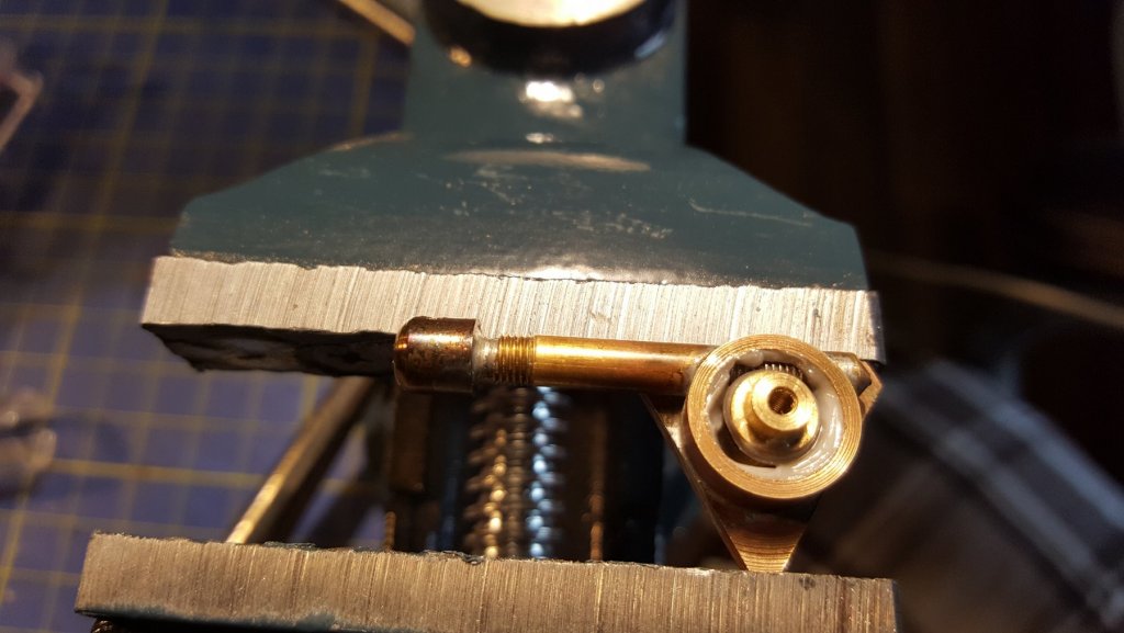
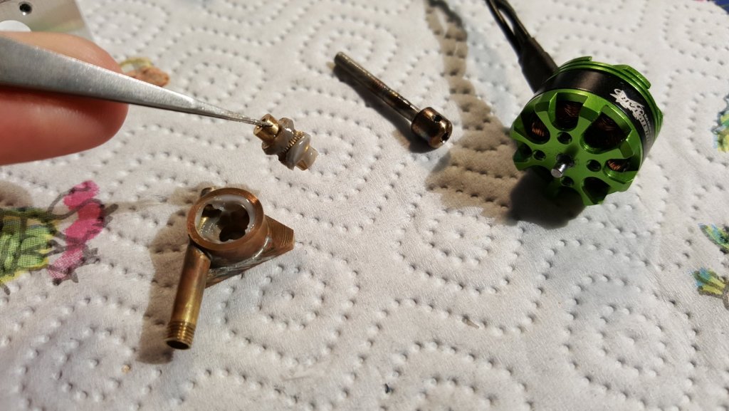
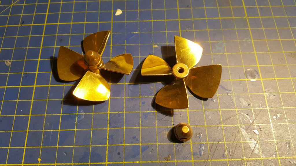
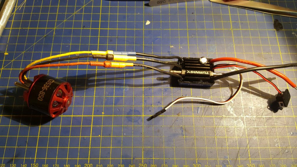
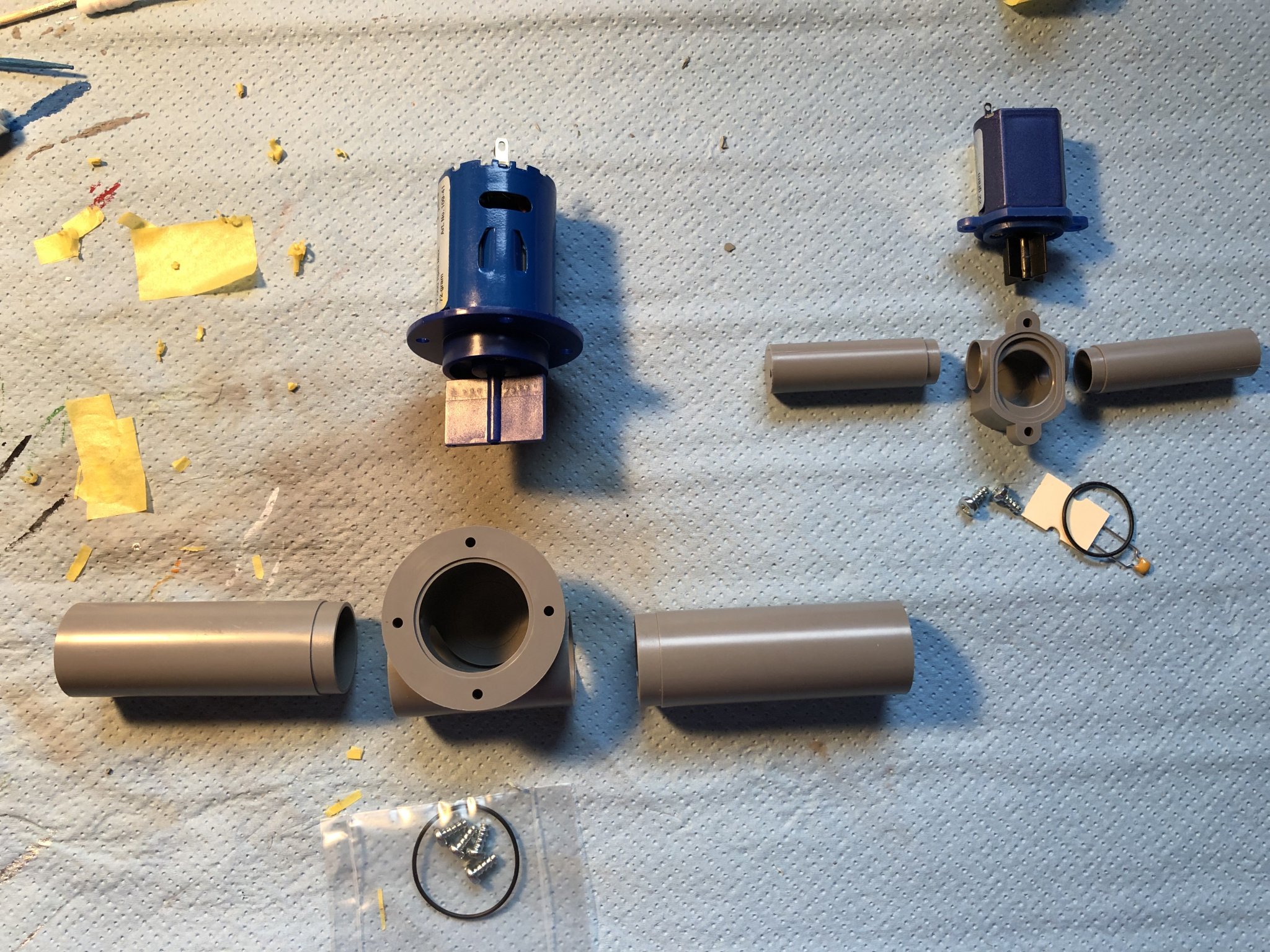
Finally the thrusters are complete The body is made of bronze, the drive shaft/worm is made from an M3 screw and the worm gear is made of brass. The final gear ratio is 1:31 and the driving engine should mahe max RPM of 28800, this then gives around 930 RPM on the propellers. The basic parts of the thrusters; body, worm gear, the worm/drive shaft, and the engine. the assembled unit, with the pair of propellers. The stern unit painted red, and taped for grinding the exes material of the aluminium engine mount. both units are finished, the frornt is glued together, the rear will be glued once inserted into the hull. Enlarging the rear thruster hole, lots of dust... Also some parts came.. The pair of the main propellers, 50mm diameter blade design for kort nozzles, of course Left Handed (LH) and Righ Handed (RH). And the speed controllers (ESC) for the main engines: These are marine ESC's with maximum of 30 A of continuous current, the engines are rated for 28 A burst for ~30sec. As one can see the brush-less engine has 3 wires leading from the ESC into the engine. By changing the connection of two of those wires the engine changes its rotation, without any impact on performance of lifespan.


- 90 replies
-
- 3
-
-
- fairmount alpine
- billing boats
- (and 1 more)
-
Thank you everyone. I hope to post some interesting pictures this week, since the thrusters will be complete however I'm not sure if I'll be able to build for the next week, I fell of my bike on the way to school... George
- 90 replies
-
- 1
-
-
- fairmount alpine
- billing boats
- (and 1 more)
-
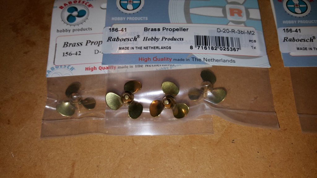
Yesterday some goodies arrived, the propellers of the two thrusters, which are planned to be finished tomorow. A two pairs, each thruster has a LH and a RH propeller.
- 90 replies
-
- 5
-
-
- fairmount alpine
- billing boats
- (and 1 more)
-
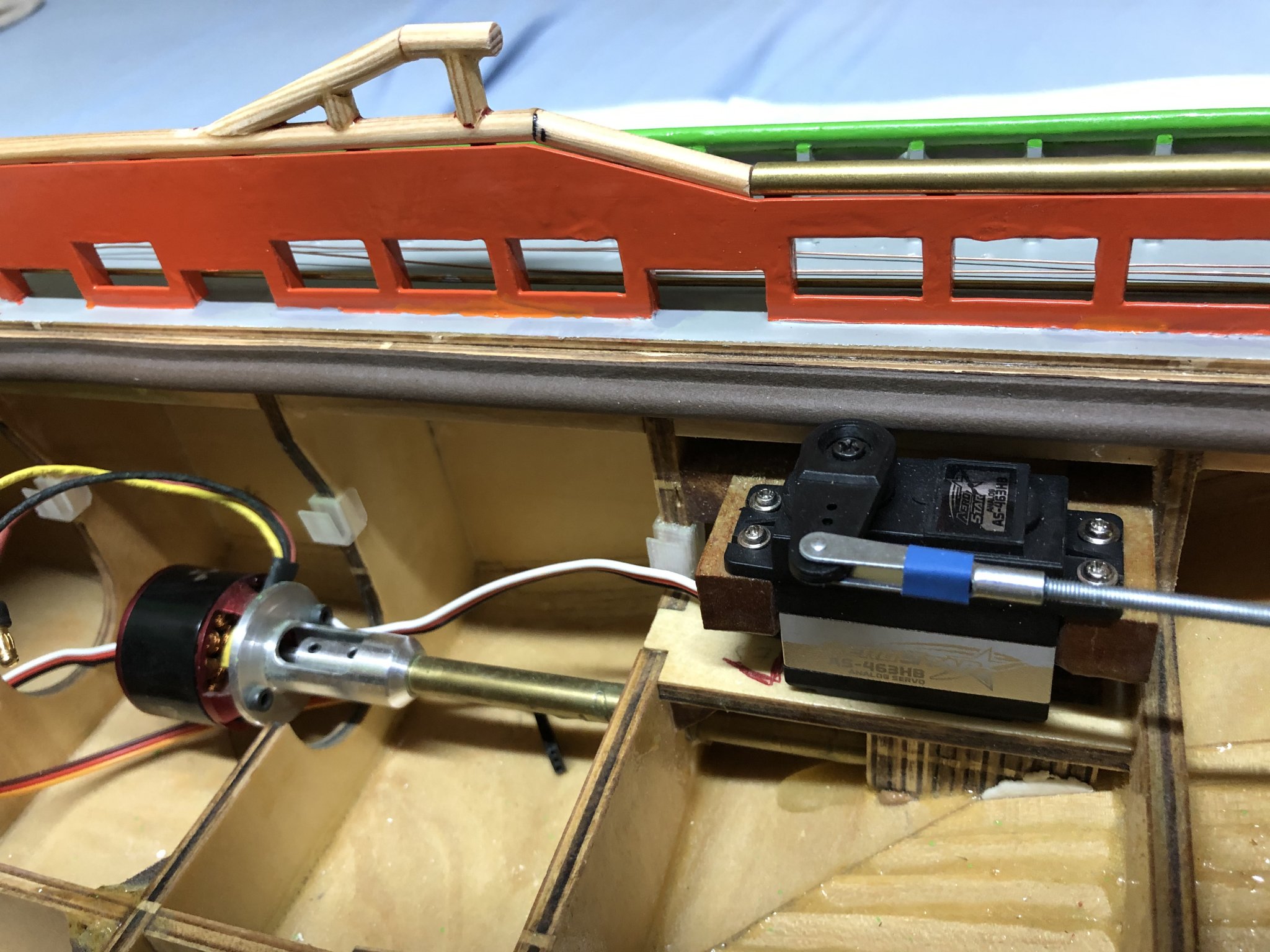
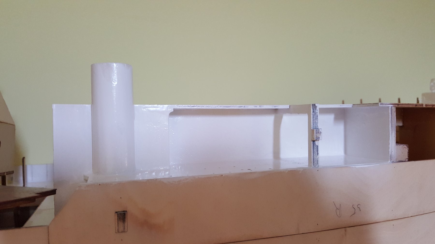
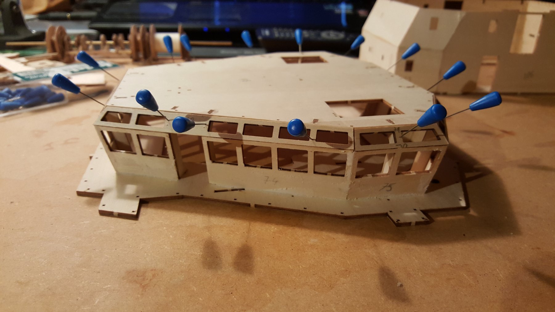
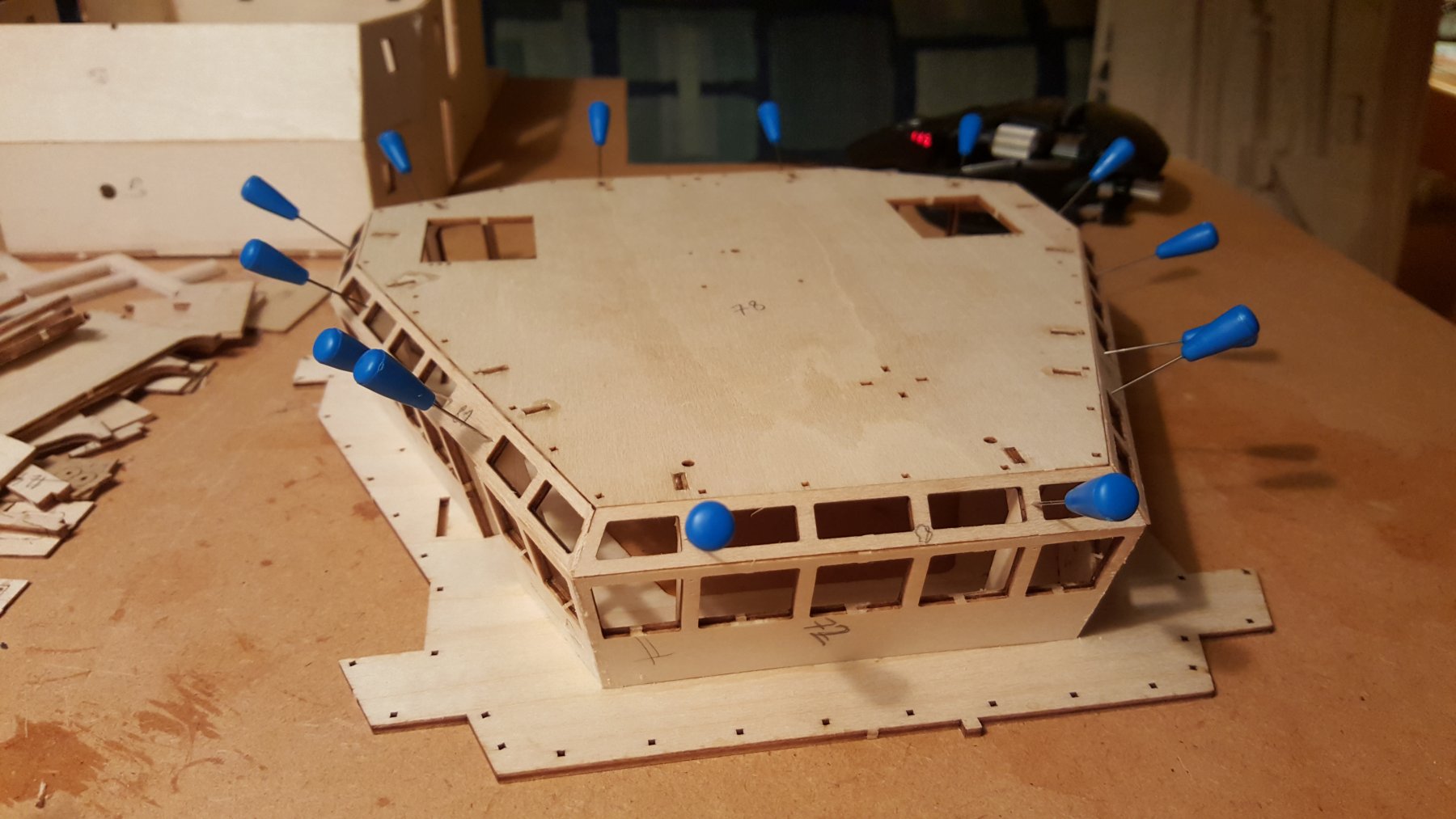
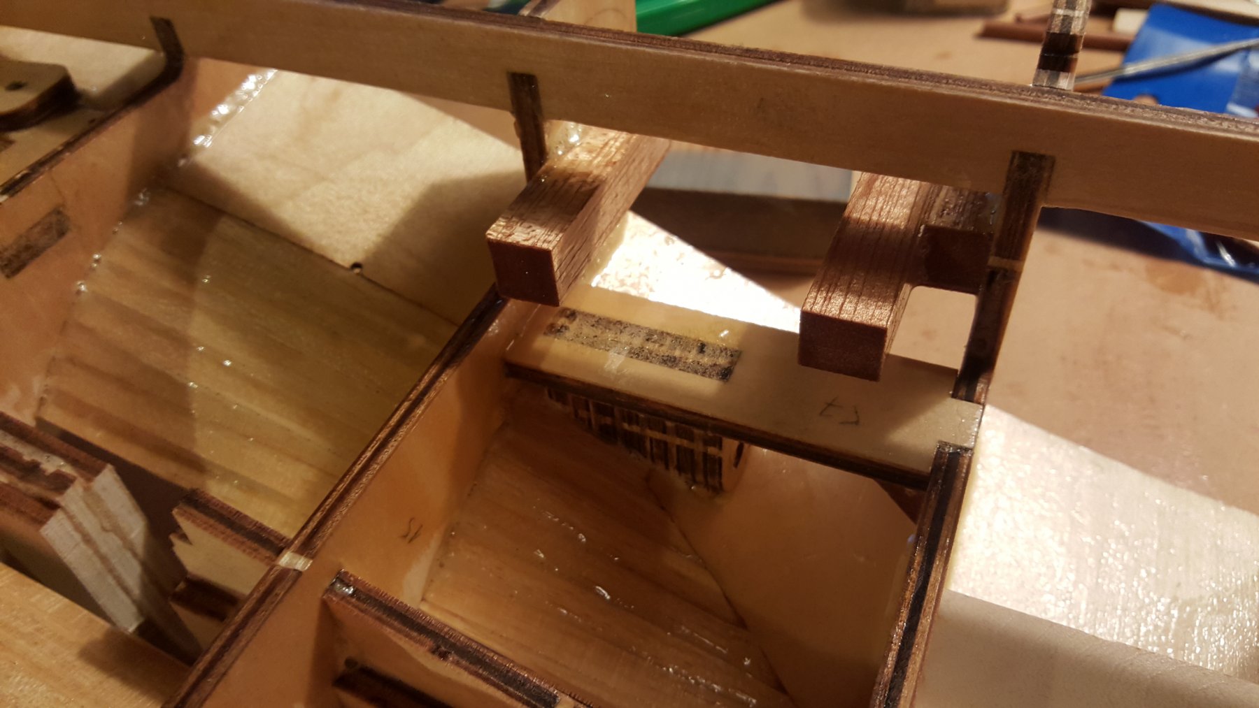
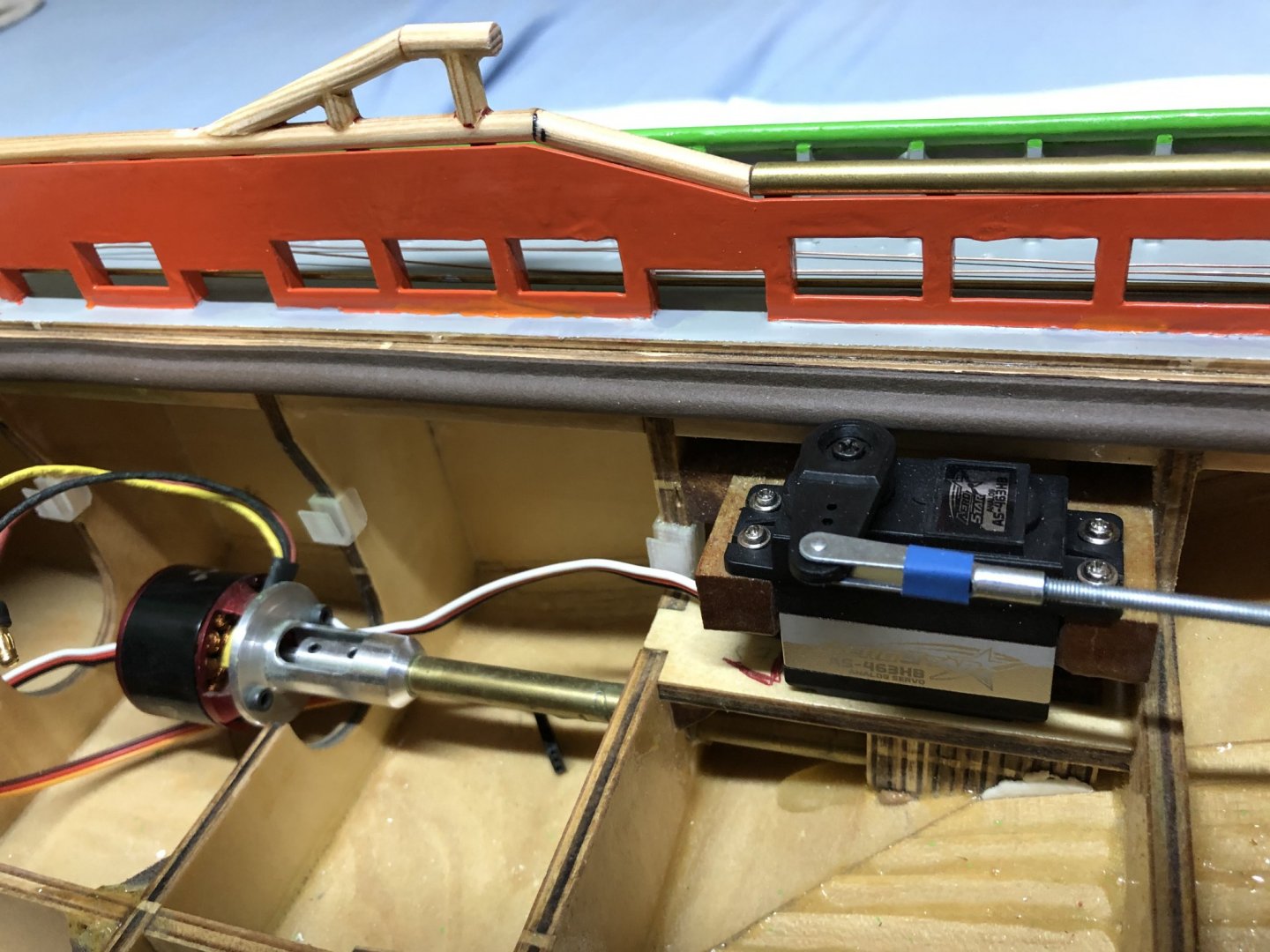
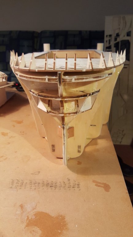
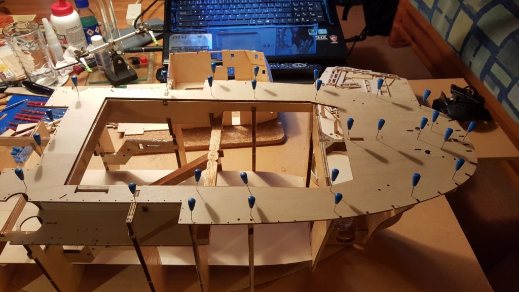
Continuation on the Hull: Since the bottom was already attached and I got the order of epoxy, I started to waterproof the base structure of the hull. Here is also added the deck for the electronics, that are going inside. The stern view of the ship. With the view of the added servo mounts, one servo per rudder, this will allow for independent rudder movement. The details of the servo mounts. They are made out of the remaining pieces of the hardwood dowel used to create the towing-rope anchor in the hull. The Decks: After waterproofing of the hull with epoxy, the main decks followed to be glued to place. The bow deck is being glued to place. The stern deck with the supports for the side planking and the inner supports for the towing rope leads. All of these supports were first glued to place by a drop of super glue, then secured to place by epoxy from the bottom side of the hull. Dry-fitting of the bow supports. Now it looks more like a piranha fish, the a boat Front view of the bow supports. The Bridge: Next on the list is the bridge. Here I must say that, the kit is really elaborated. The non right-angle joints are made by scraping, I would prefer to have a modeling wood plane for this work.., the two joining parts. With some patience and a sharp scalpel this was easily completed. The lower part of the bridge. Details of the angle joins of parts. The inside of the entirety of these joints is to be coated with epoxy. Glued lower part of the bridge with dry-fitted the upper part. The Assembly of the upper bridge. the roof will not be glued, for I intend to make the interior of the bridge. For which I managed do find a few pictures on the web. The upper windows are being glued, the roof is there just to make sure, that everything fits OK. Finished control room exterior. Now it will wait for the interior. The last for now is the crane. P.S. If someone is still following I do apologize for the long pauses in the vlog. I have lots of work in school right now, I hope to update this build log more often by the start of August.


- 90 replies
-
- 6
-
-
- fairmount alpine
- billing boats
- (and 1 more)
-
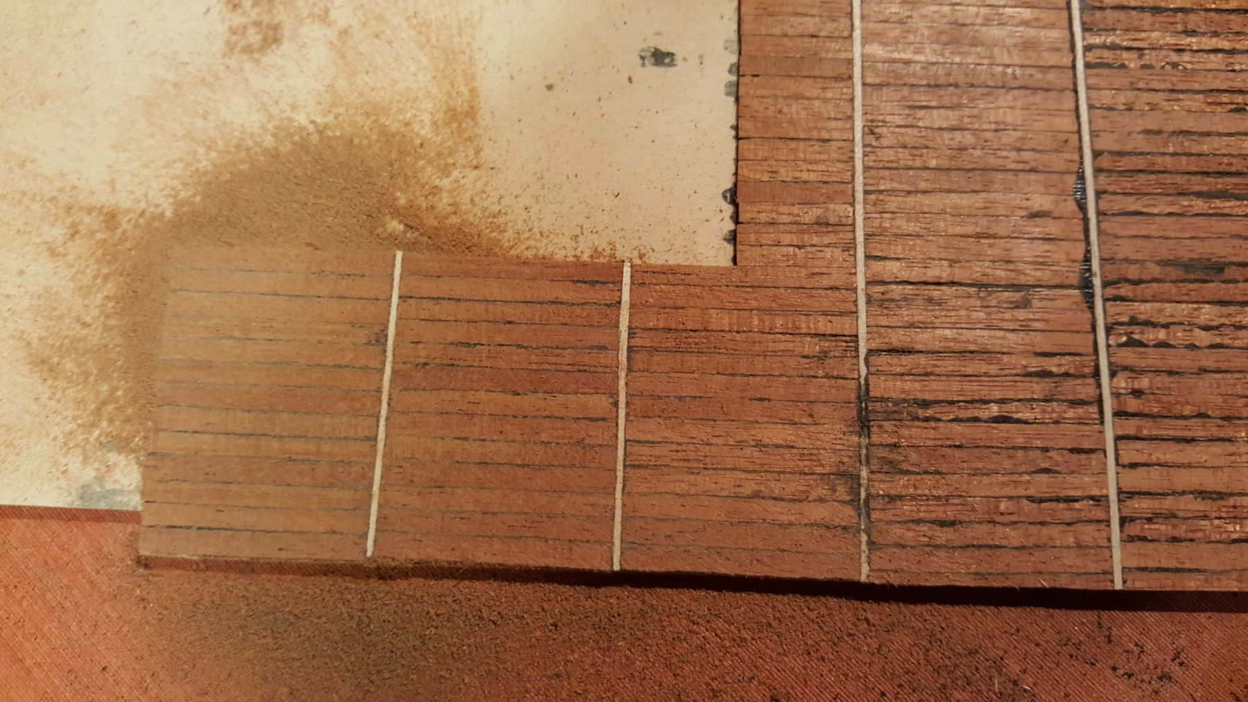
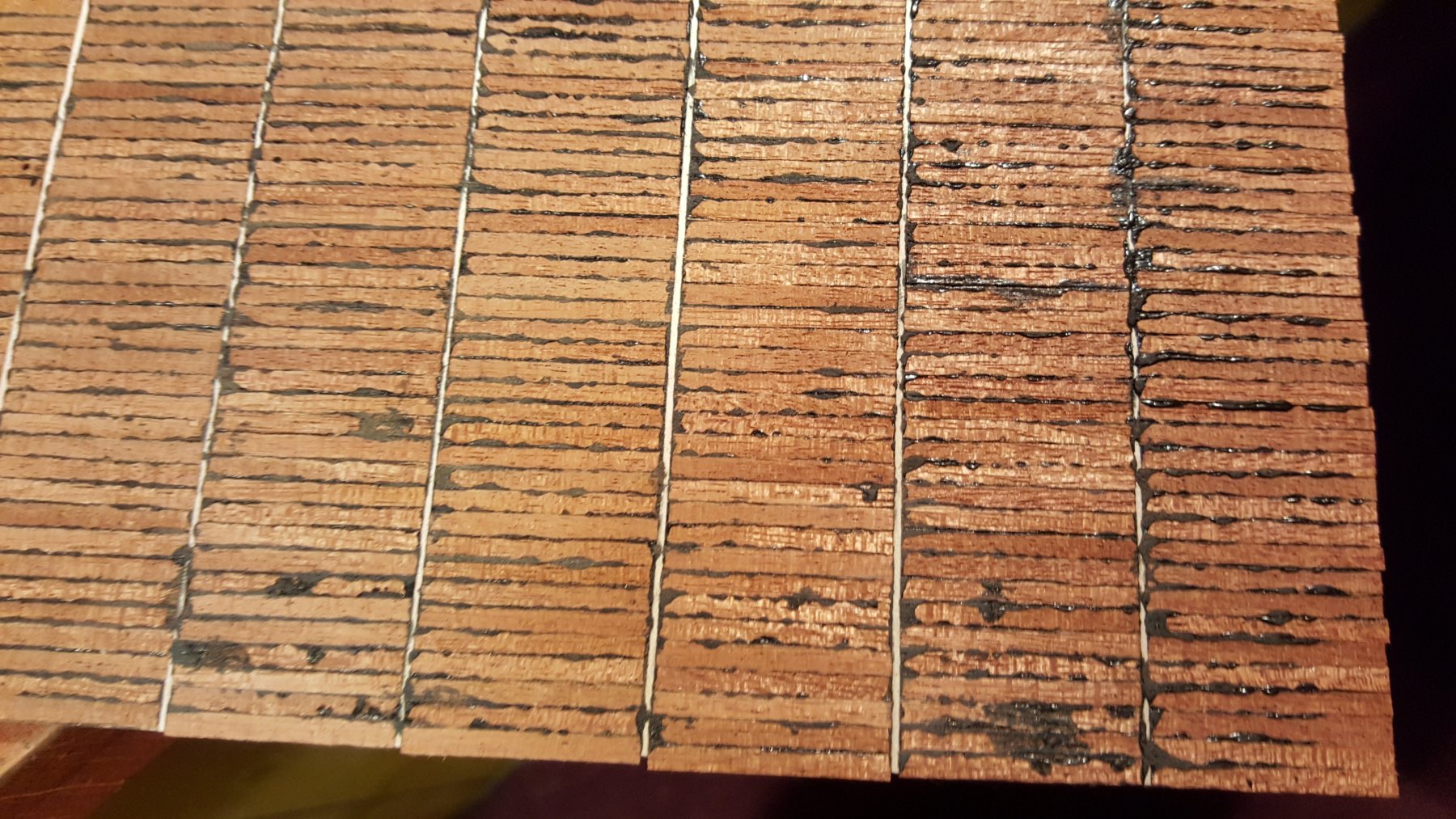
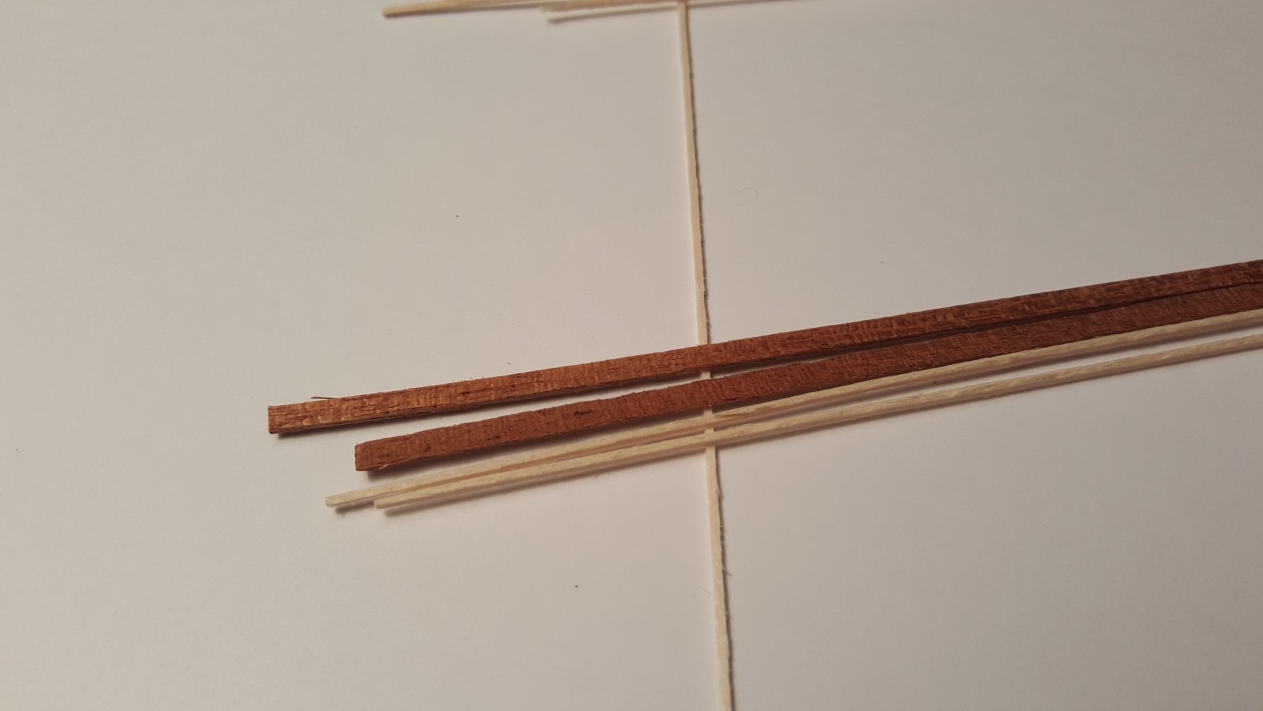
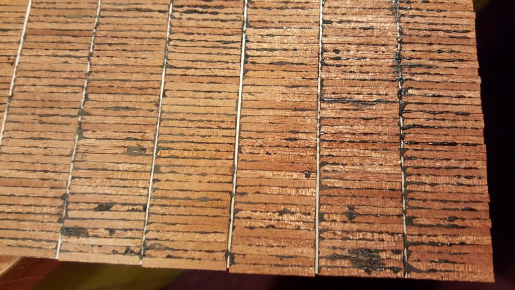
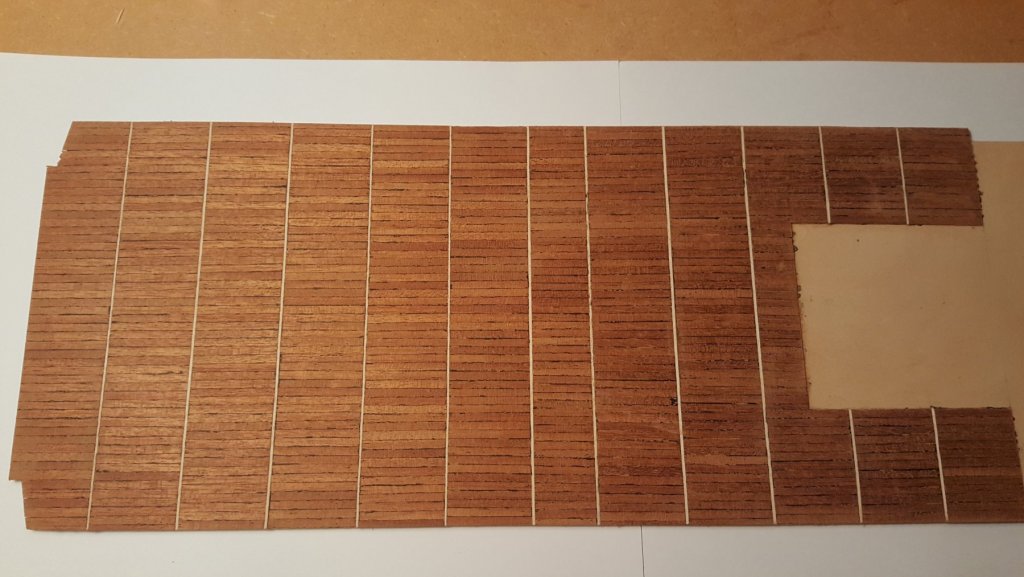
The Hull Since I am still in the process of making the thursters, the work on the ship is quite slow, usually I just glue a plank or two in the stern area. This is the one of the handful of places where actual planking is being used, most of the hull is "planked" by large pieces of pre-cut 2mm plywood, not that I am complaining, it's just that this way is easy to do and fast... Attaching the bottom parts. Started the planking of the inner stern bend. Since I didn't post for a while, I already have finished the stern planking. And here comes my first question for the more experienced members. Do you know of a trick of how to sand these kinds of surfaces? I think this is a convex surface, in mathematical terms. I used my thumb, and of course ended up burning it a bit... The Rear deck During these weeks I was also working on the rear deck, where a planked area of the deck is. For this I got for myself 18 meters of mahogany strip and 5 meters of lime strip. In the course of one day, cut the mahogany to 700 pieces and started the patient part of the process. The strips, 3x1 mm mahogany and 1x1 mm lime. The detail of the glued planks, the black stuff is PVA mixed with black color. Was trying this method out, turns out, it is quite a good one, except the amount of sanding needed to get it finished. In the process of sanding... The almost finished deck. A few more hours of sanding at fine grits, and at least 3 coats of semi mat lacquer, and it should be done.


- 90 replies
-
- 6
-
-
- fairmount alpine
- billing boats
- (and 1 more)
-
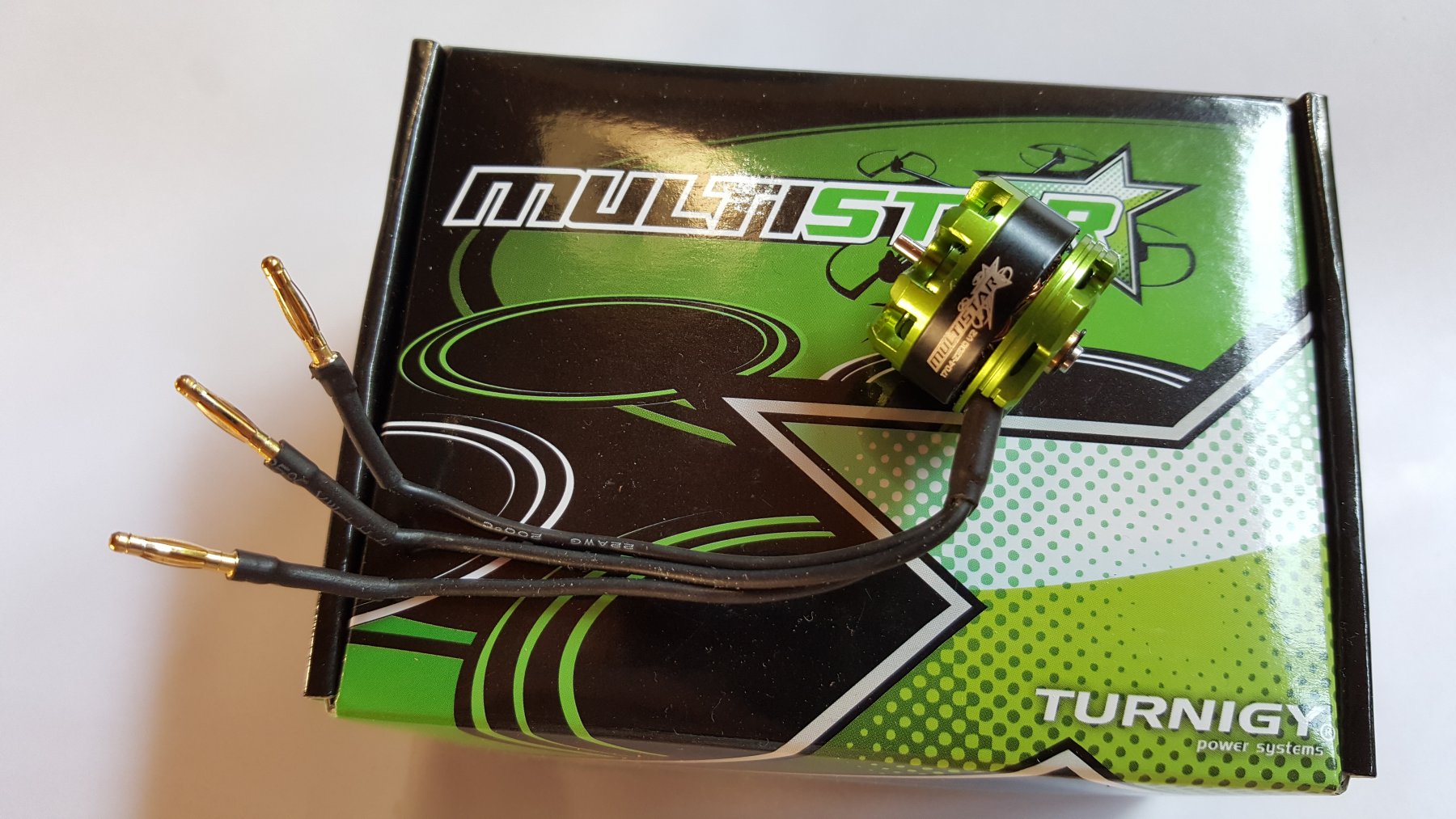
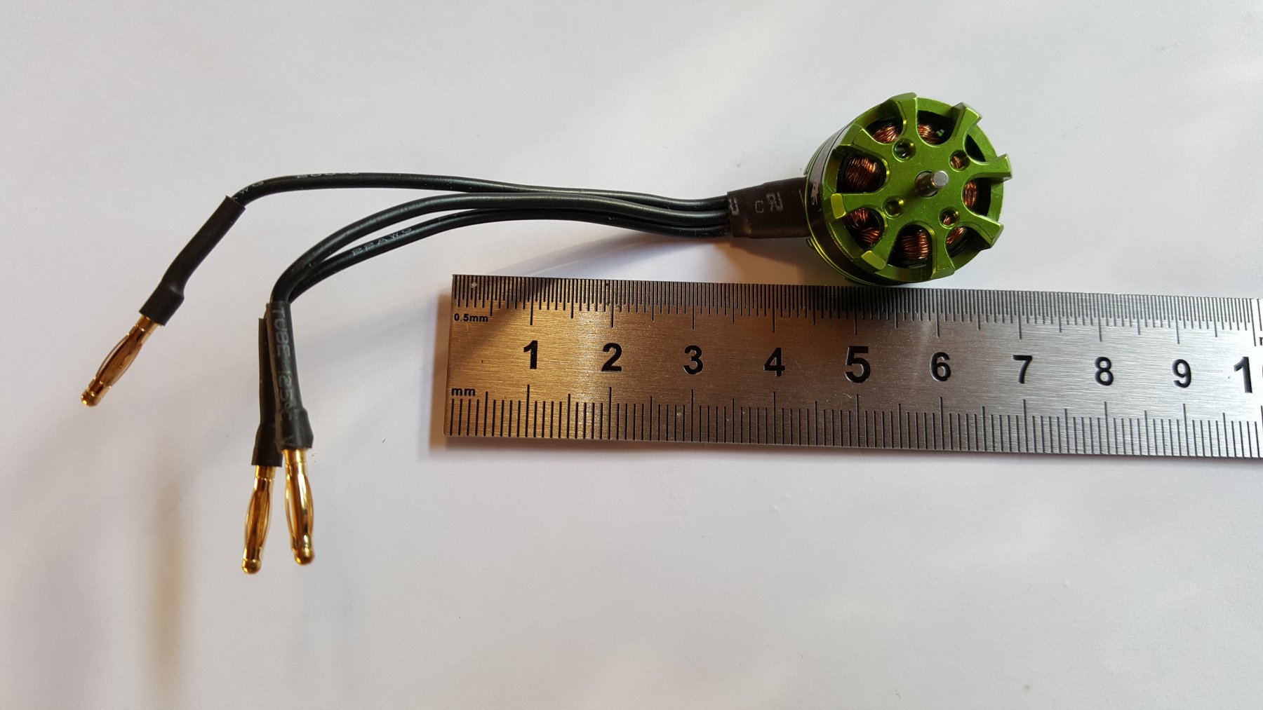
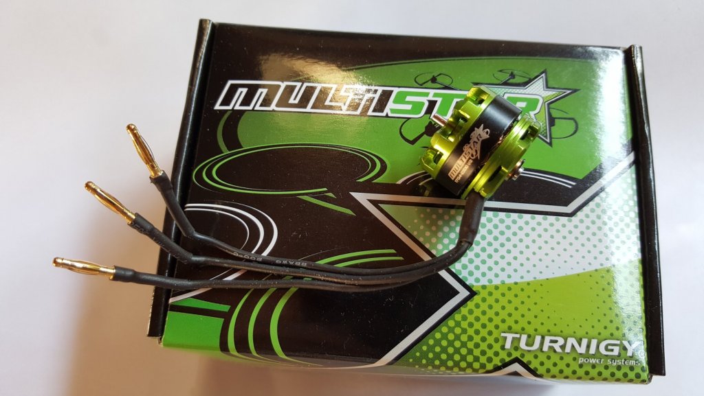
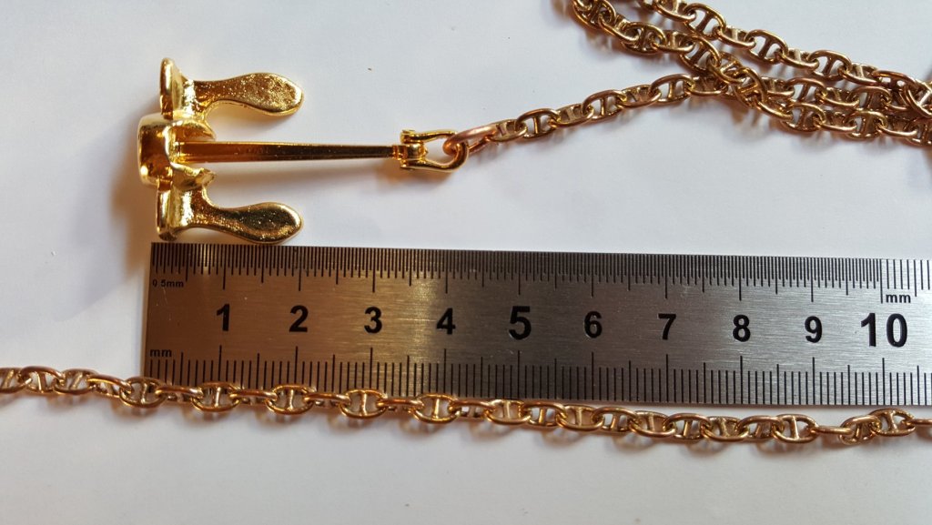
Recently some necessary parts arrived. First to arrive were anchors, anchor chains, colors and new wood for the read working deck, specifically mahogany and lime strips. Anchor with the chain installed, for now only temporarily by a copper wire. Second to arrive were thurster engines. These are really small ones, 22 mm in diameter and 16 mm thick, they are 49 W of power and 2300 RPM per Volt George

- 90 replies
-
- 3
-
-
- fairmount alpine
- billing boats
- (and 1 more)
-
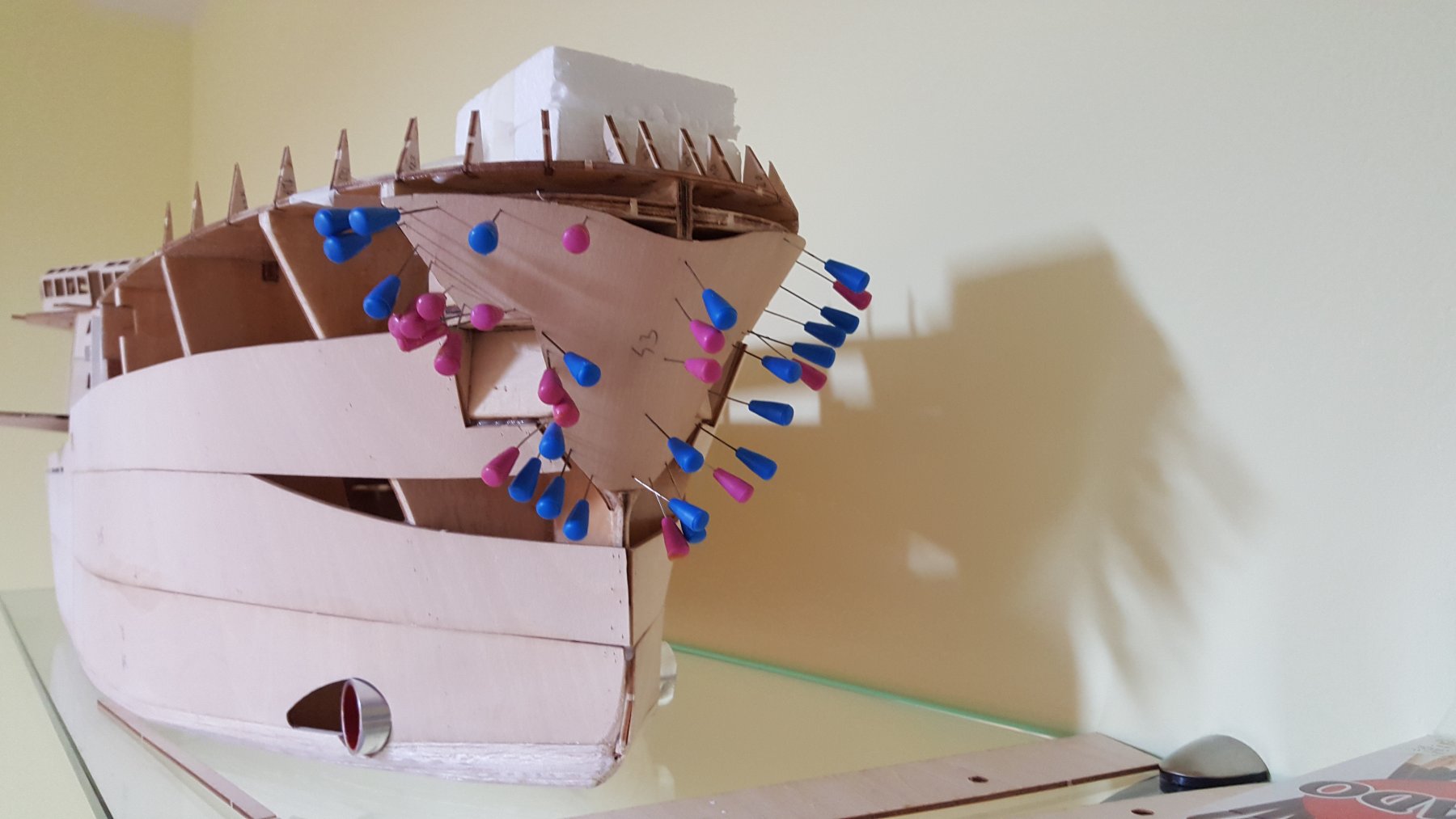
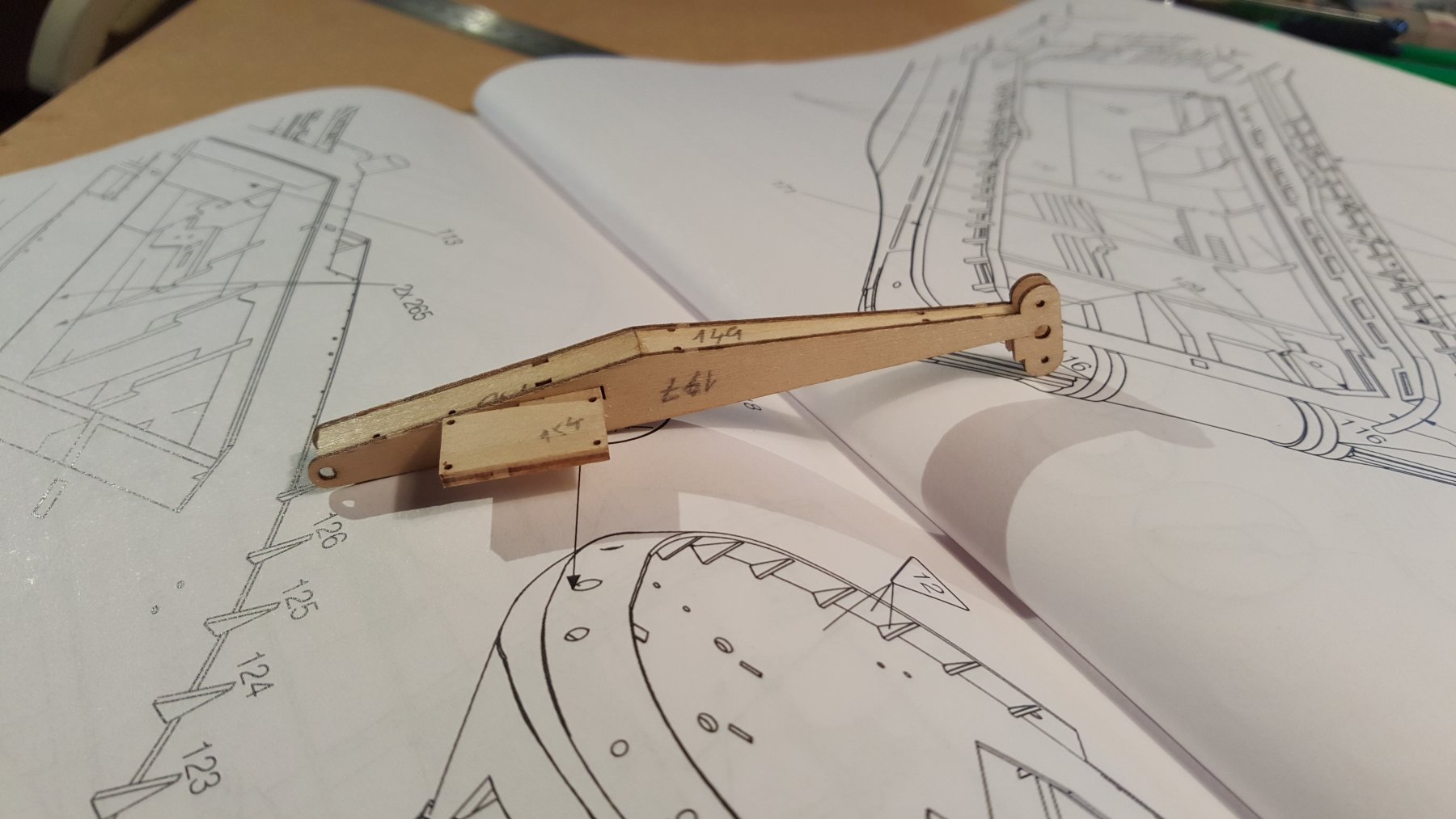
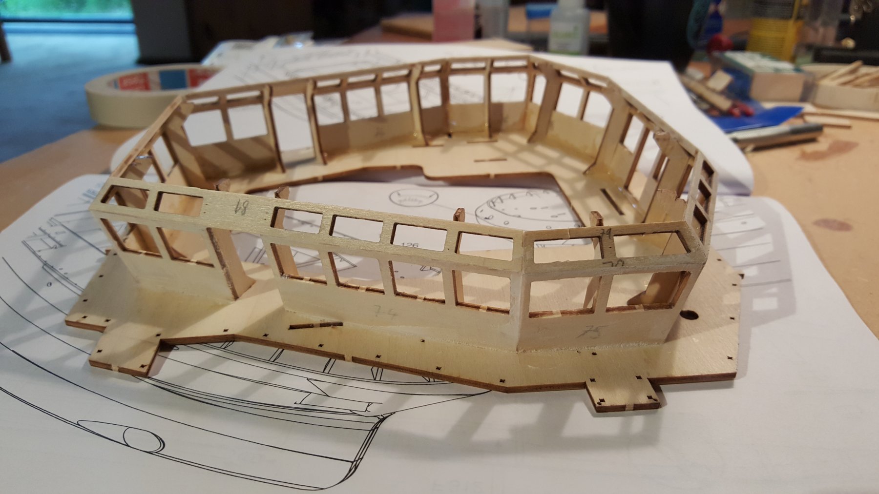
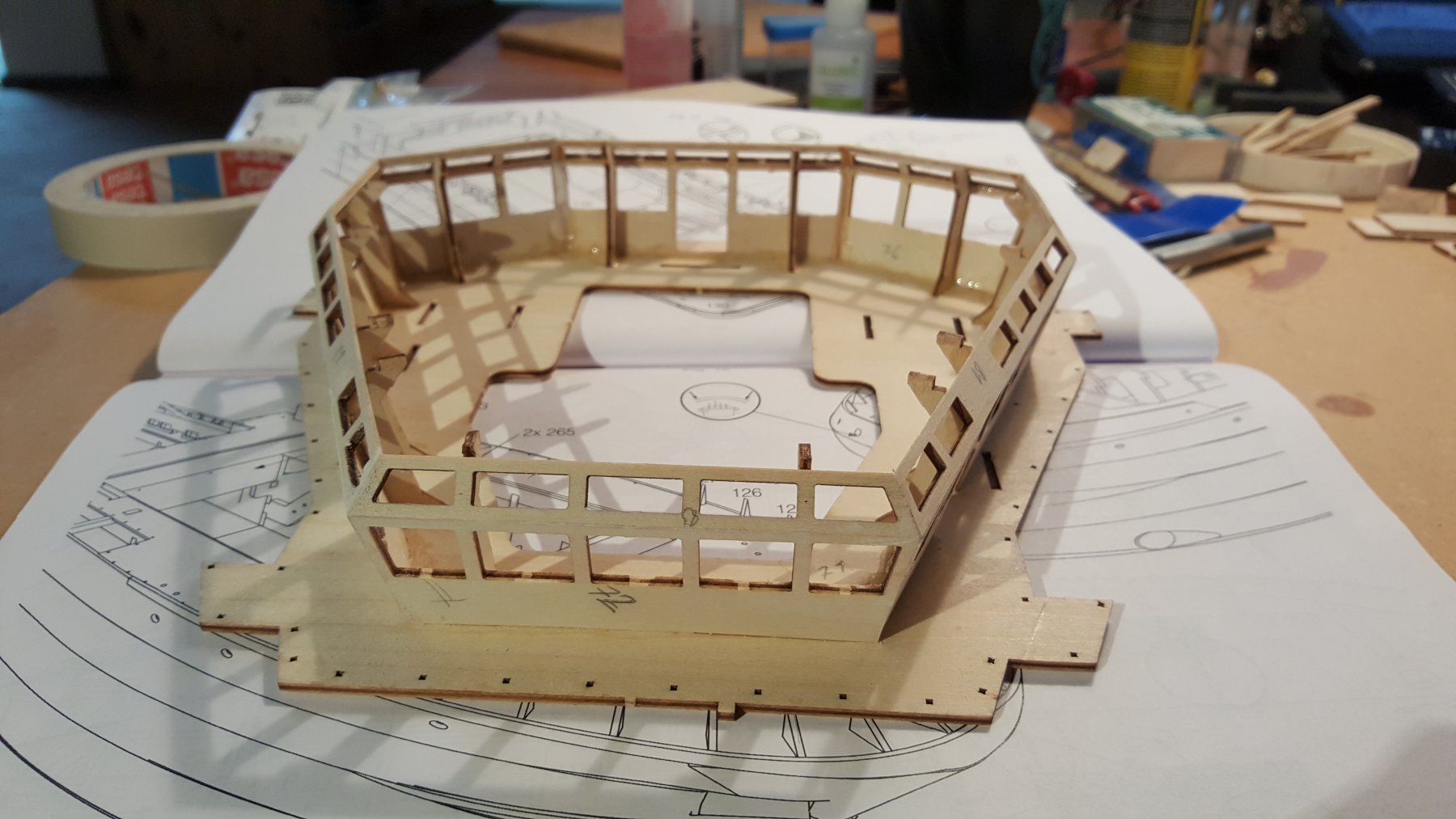
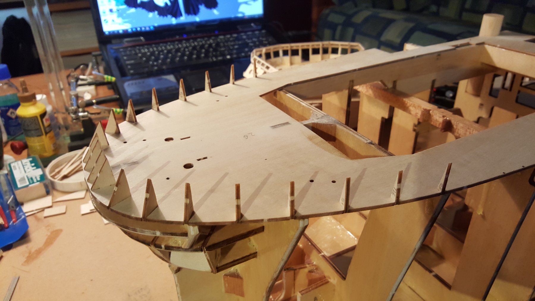
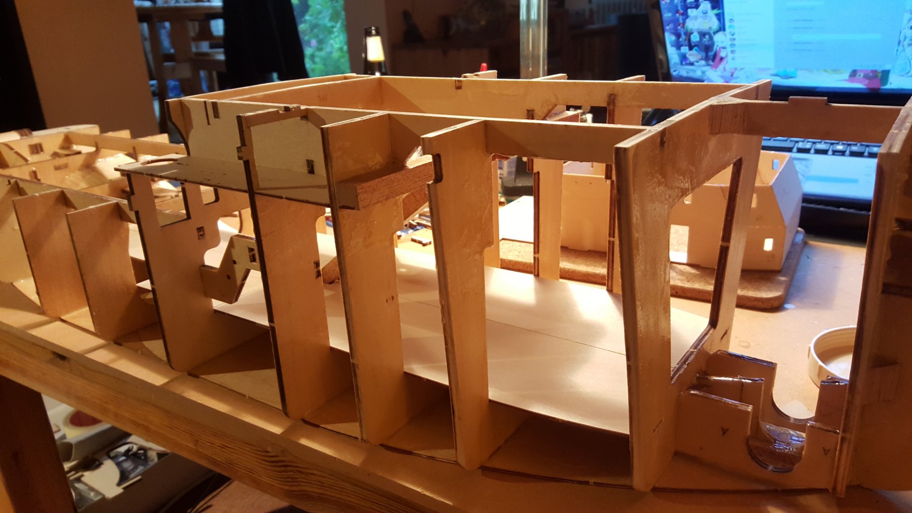
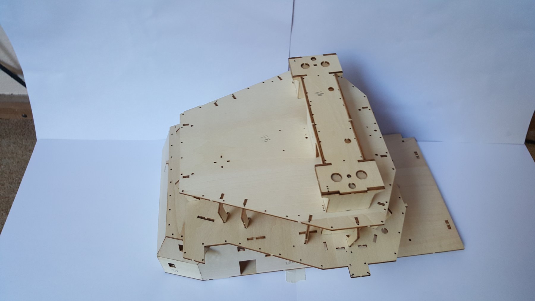
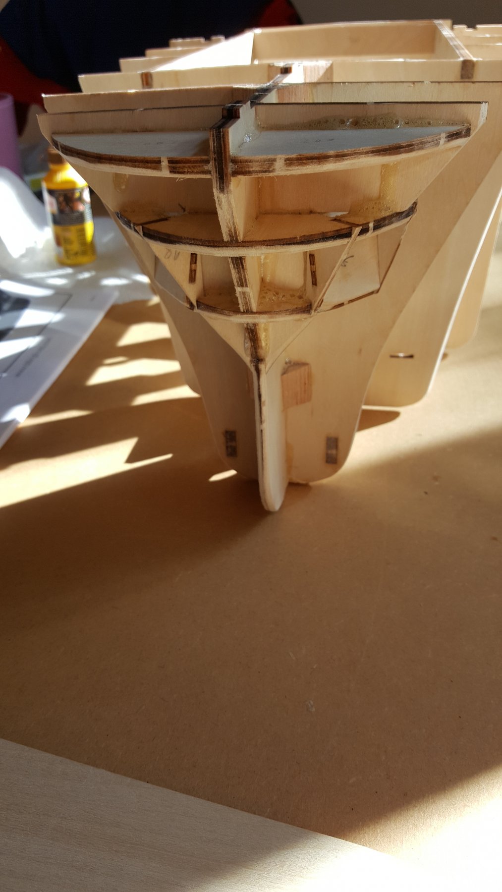
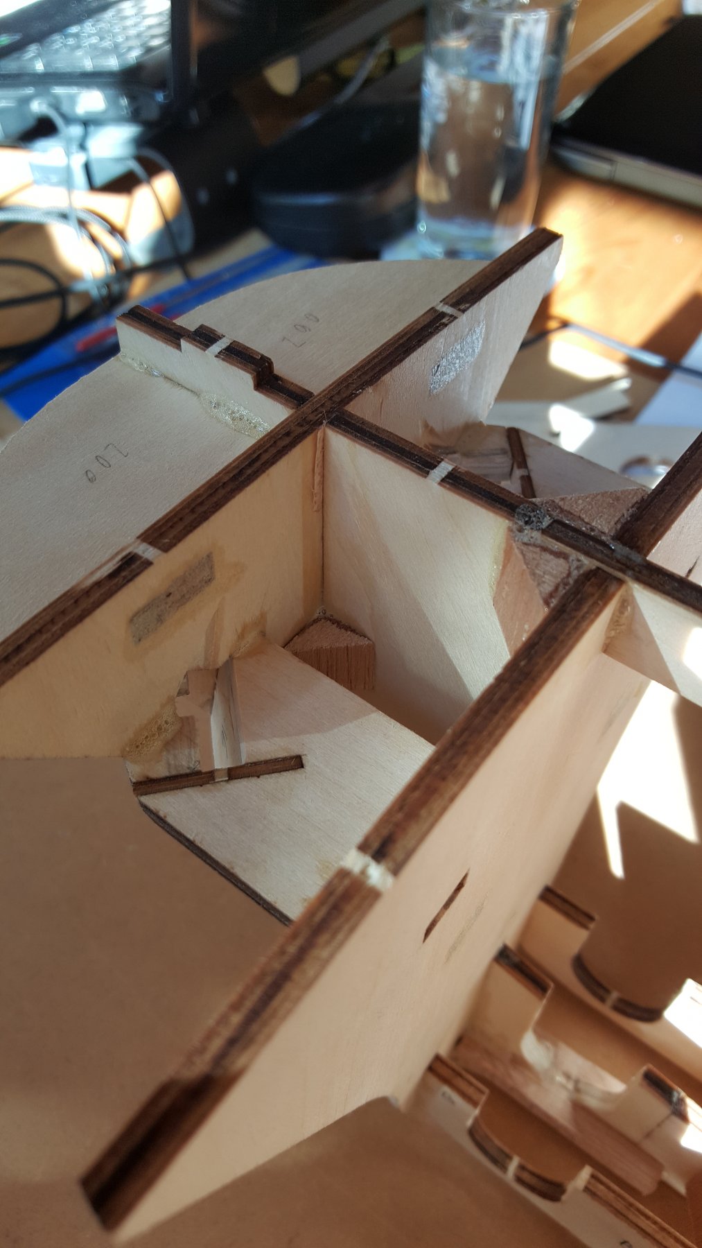
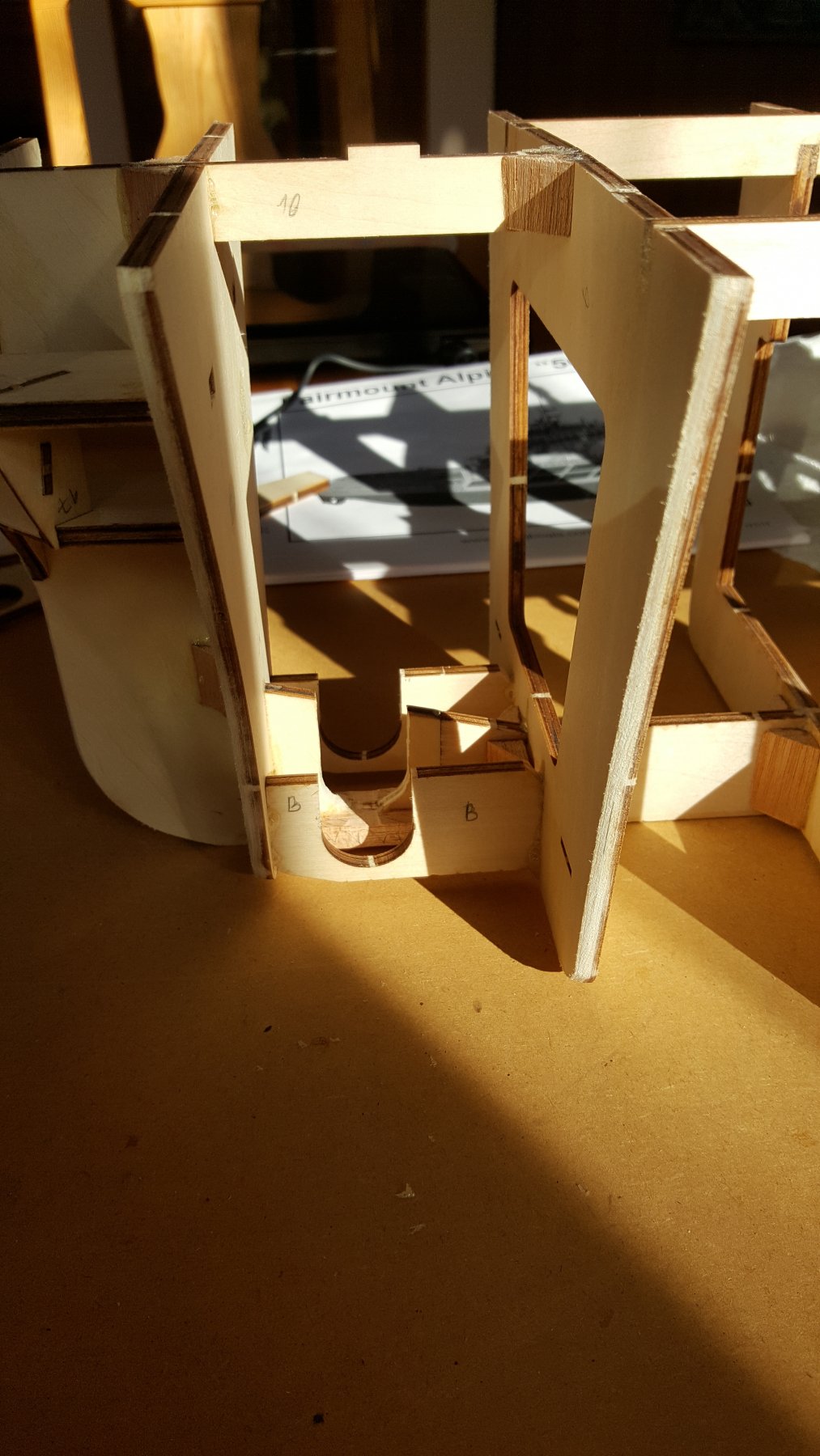
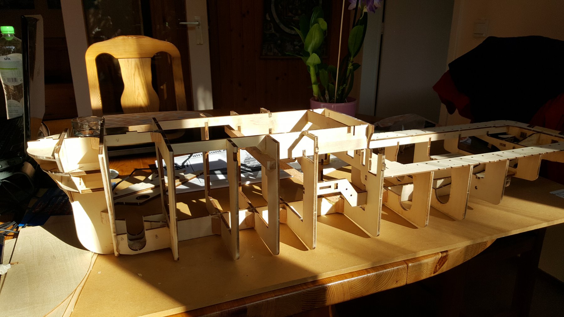
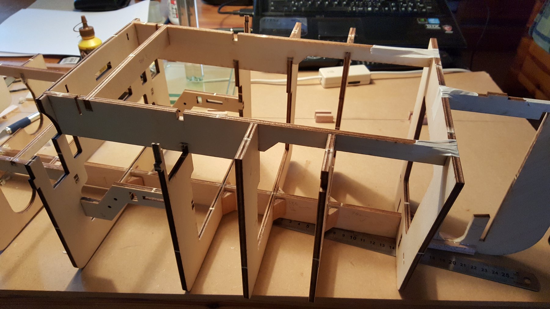
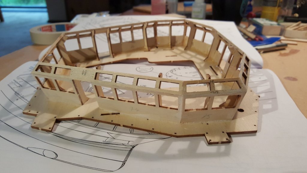
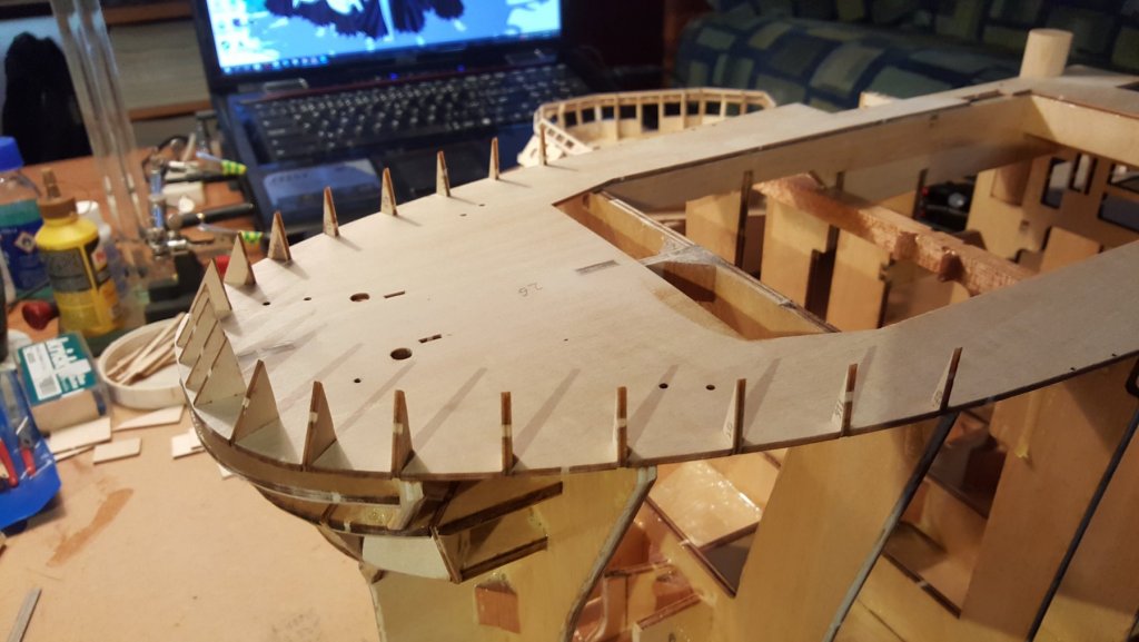
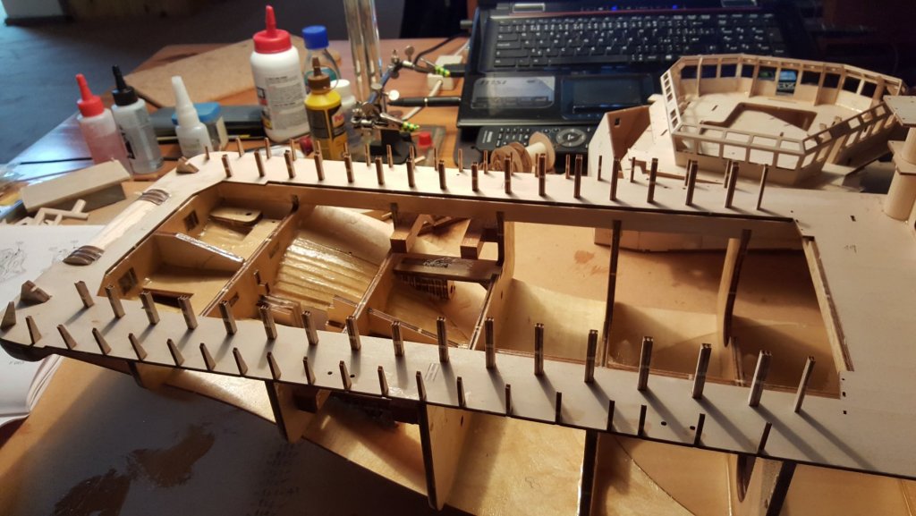
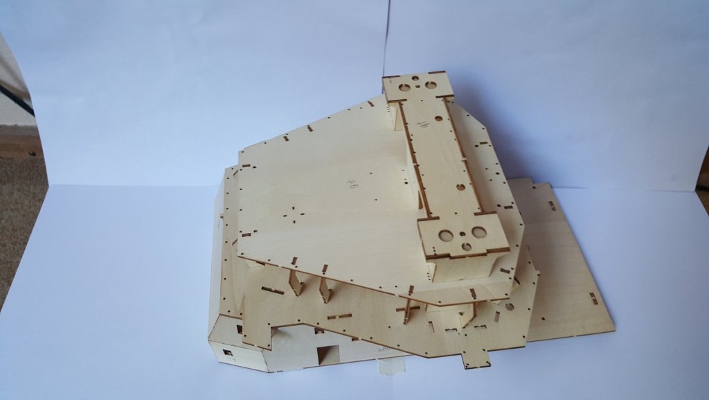
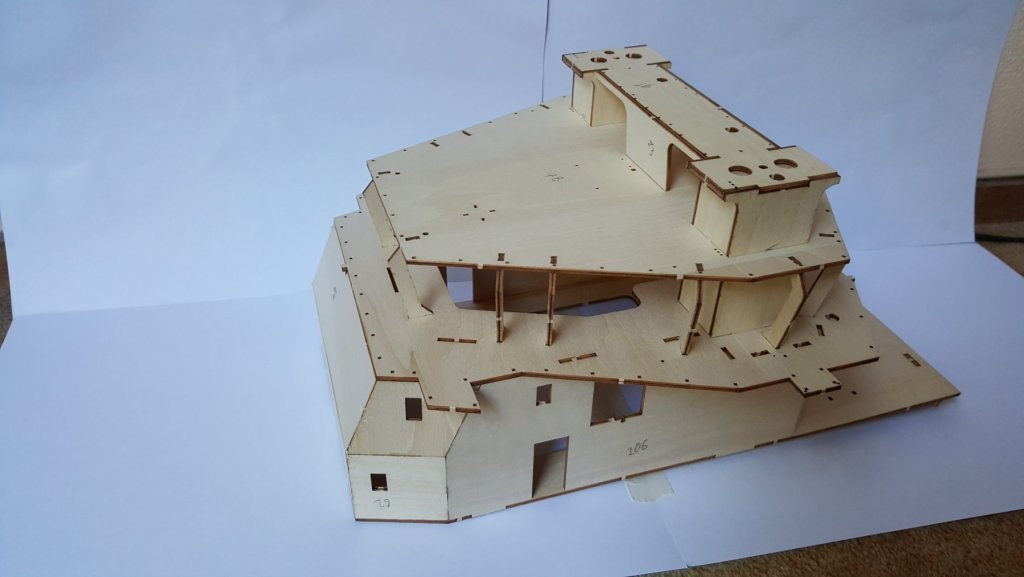
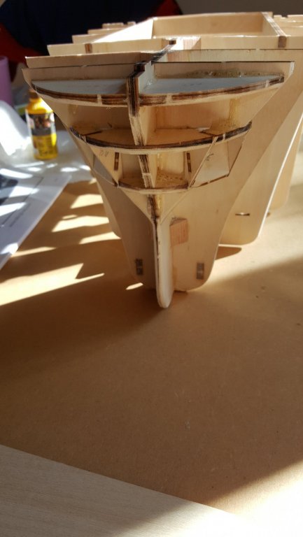
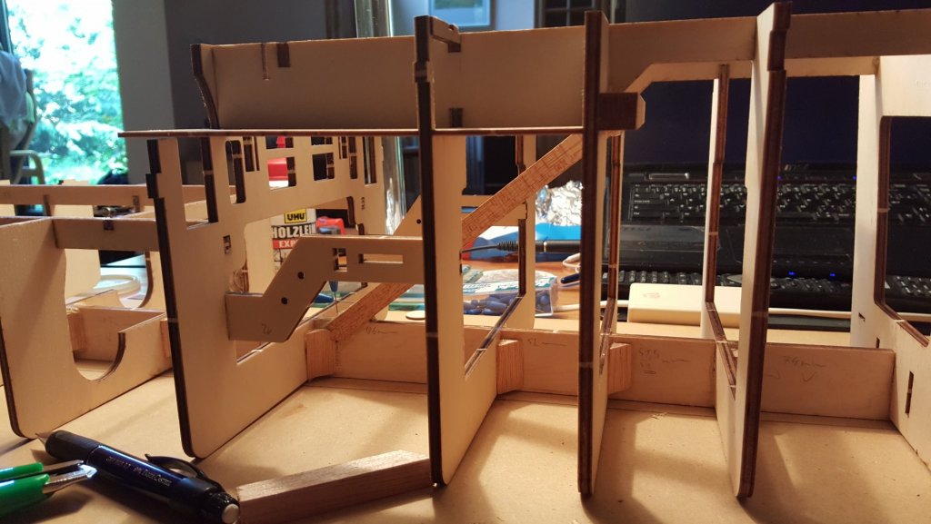
The Hull So finally the hull frame is finished, with all the modifications, that I wanted to do. The frame glued together, keeping everything perpendicular was the main goal. After extensive checks, I must say, that the level of precision is highly satisfying. The detail of the modified bow. The cutouts of the side supports (on this picture marked B ) are being kept for gluing after the bow thruster will be complete. The cutout for anchor. And the front view. It starts to look quite big George


- 90 replies
-
- 3
-
-
- fairmount alpine
- billing boats
- (and 1 more)
-
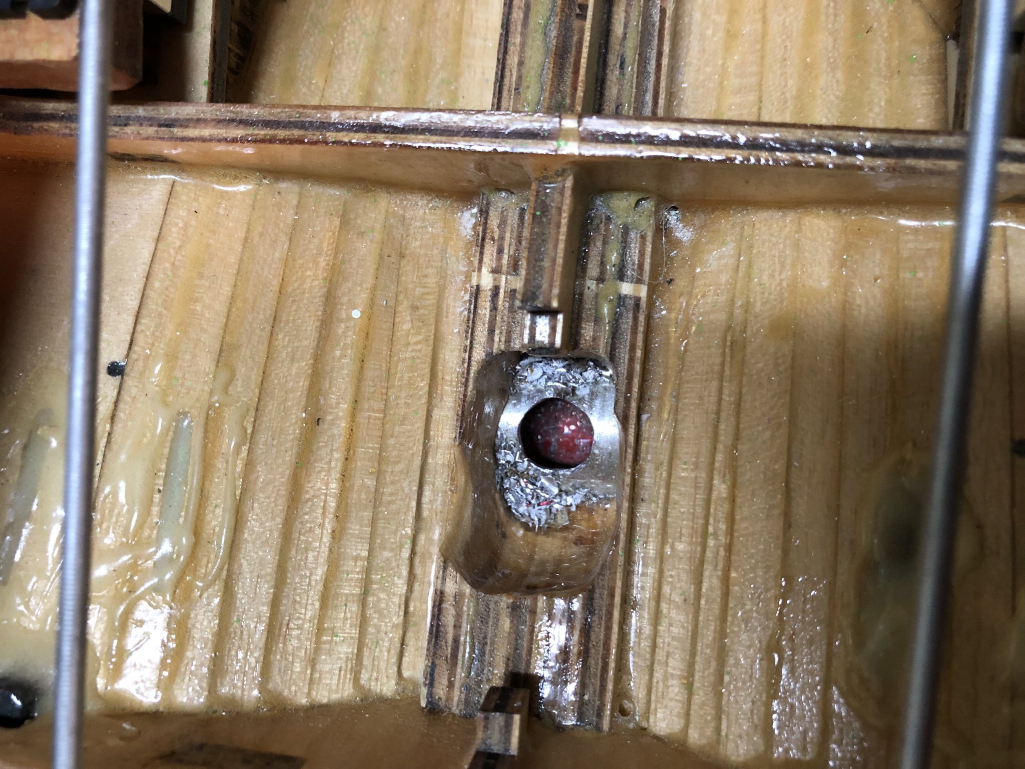
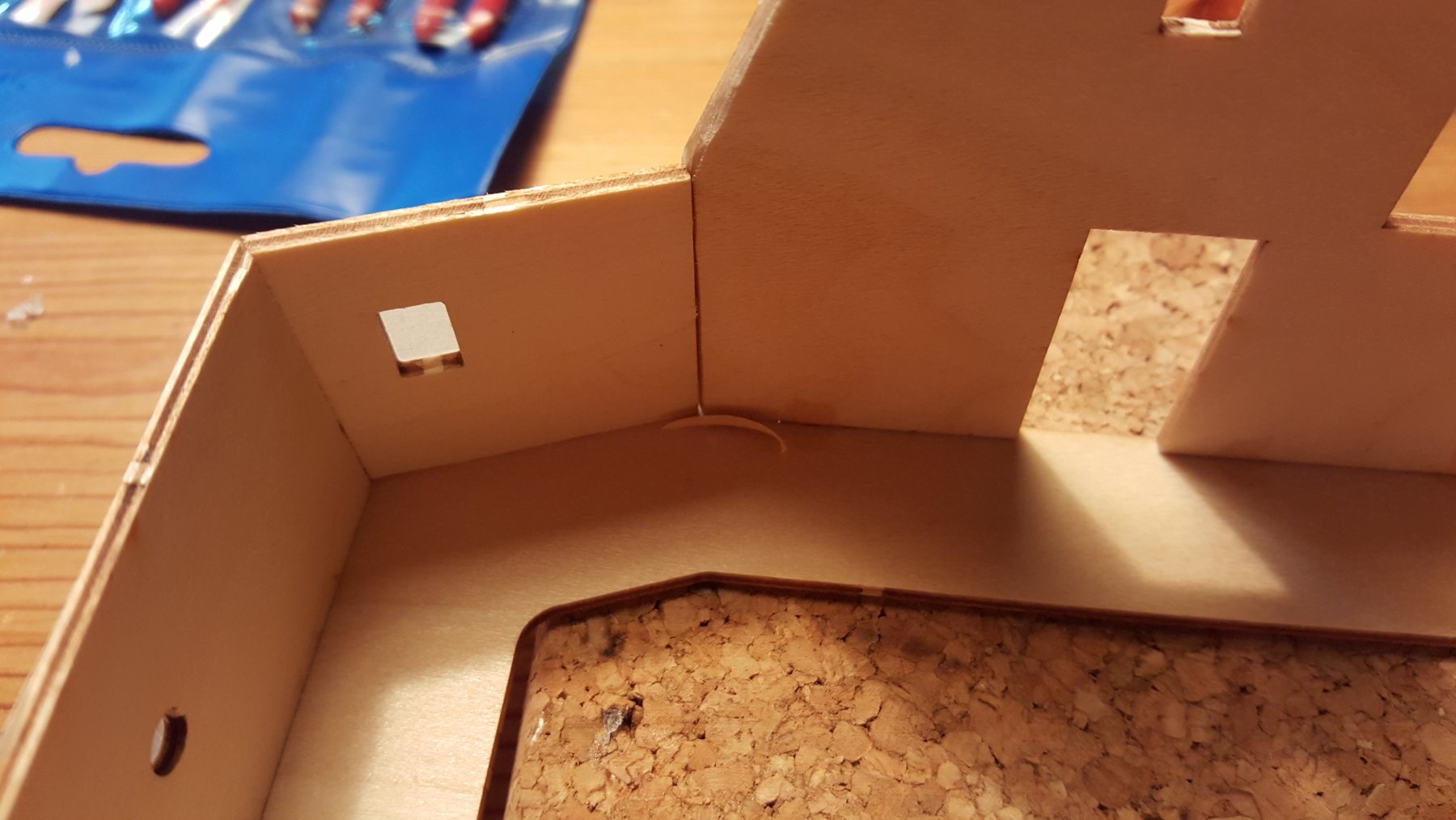
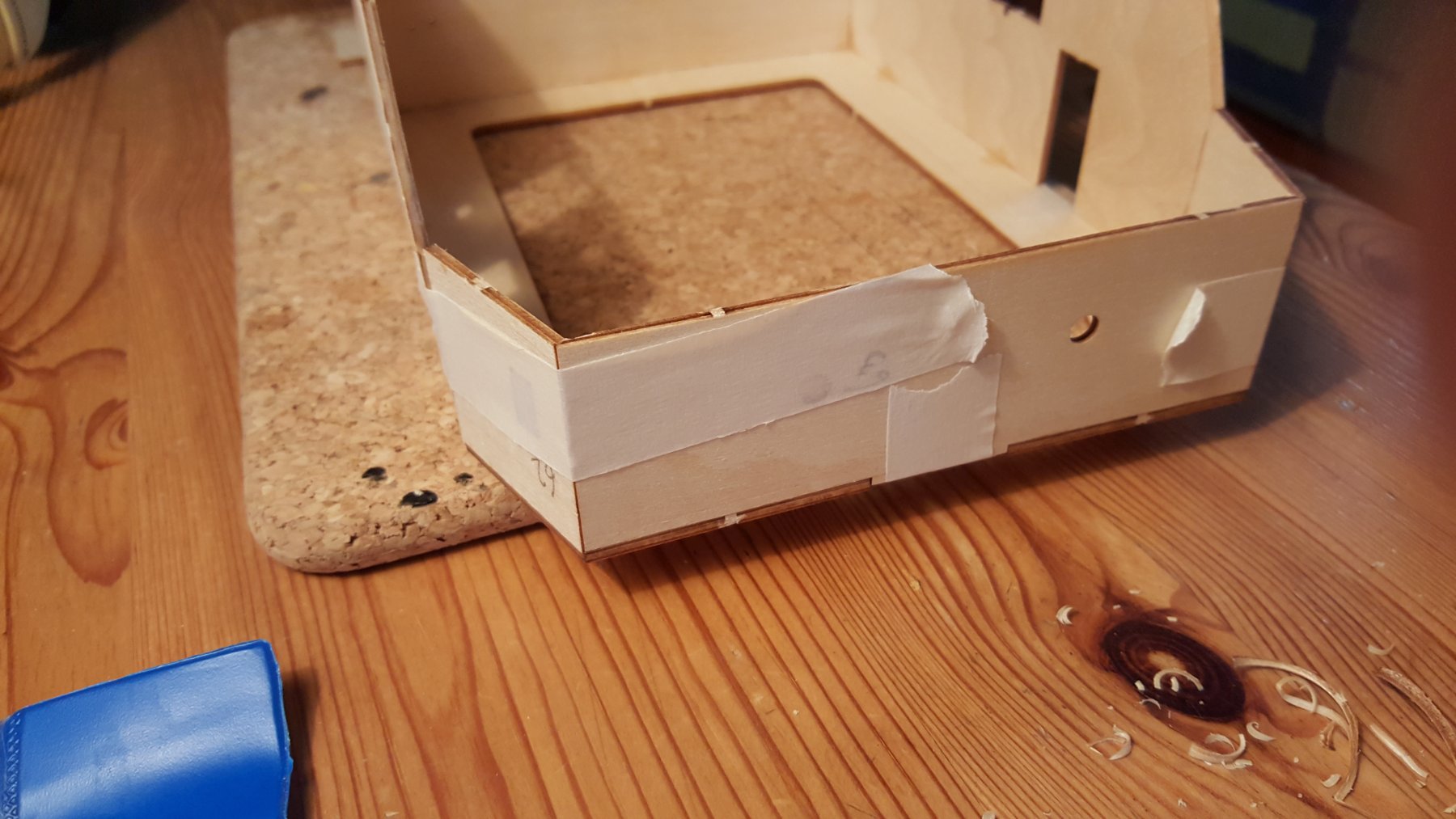
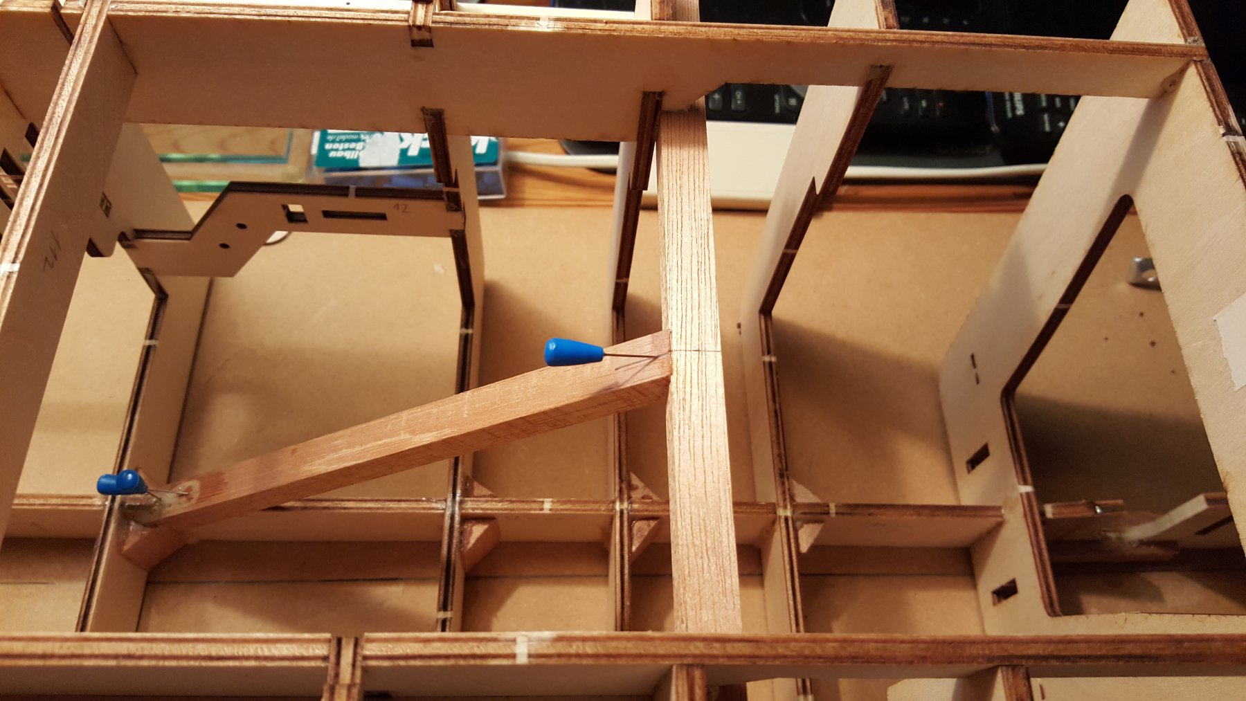
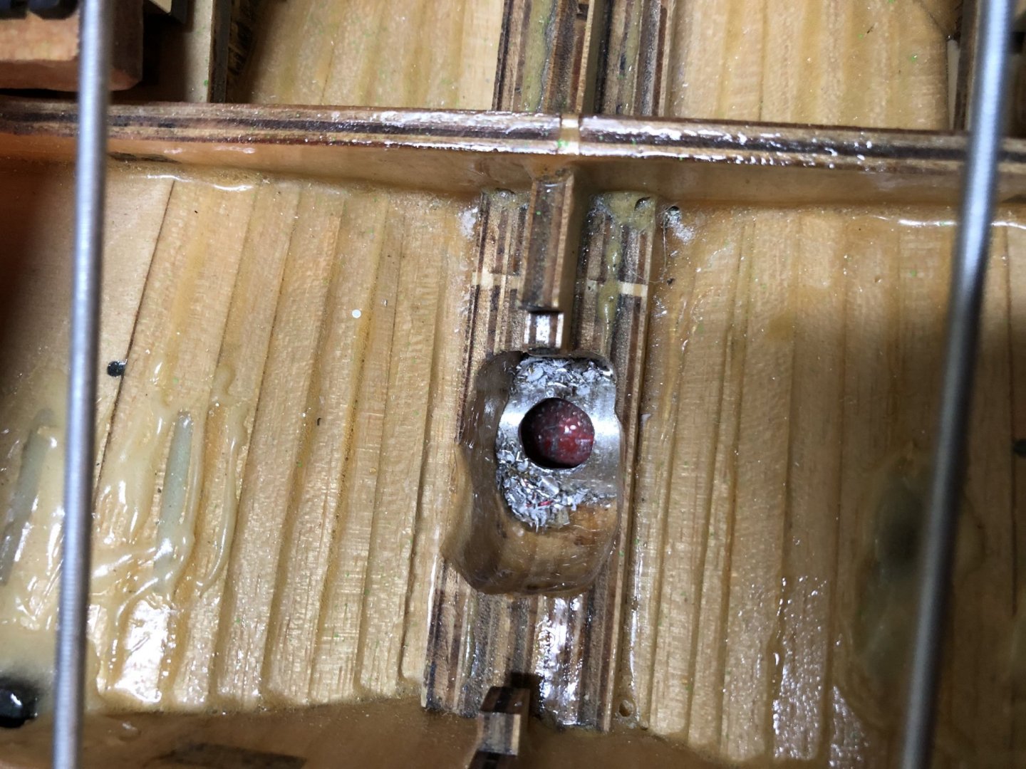
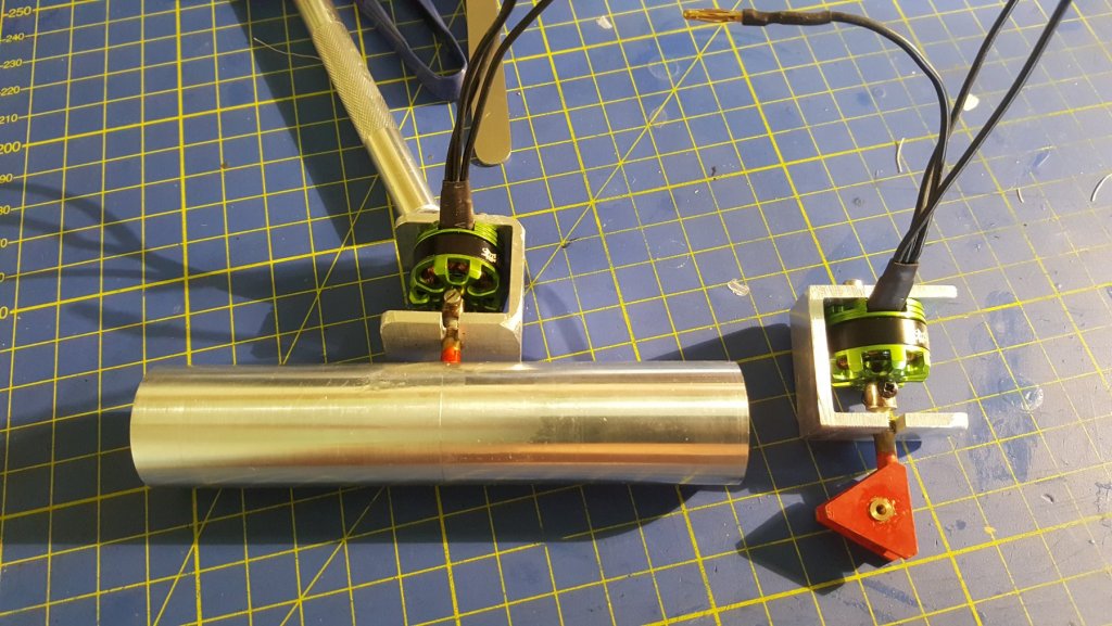
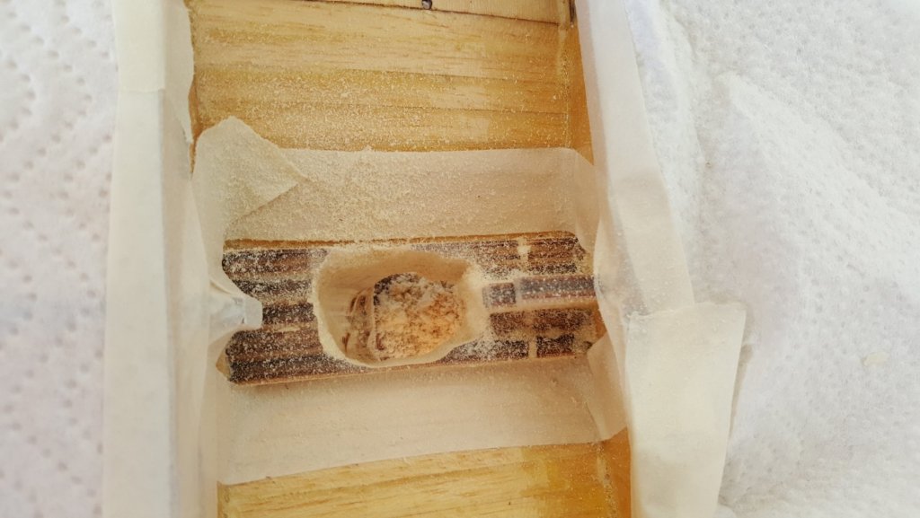
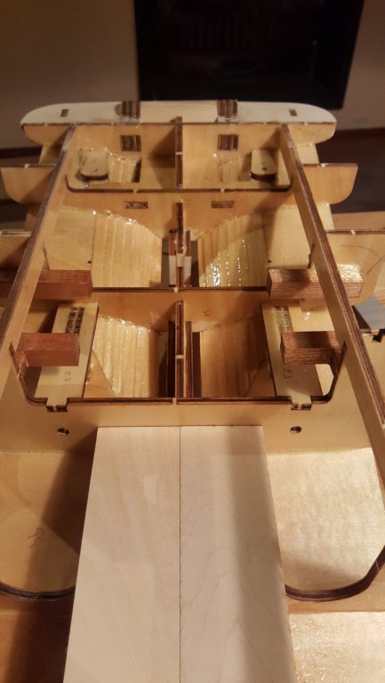
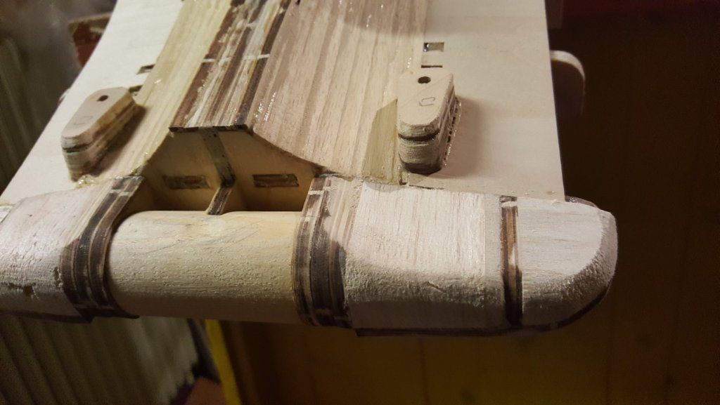
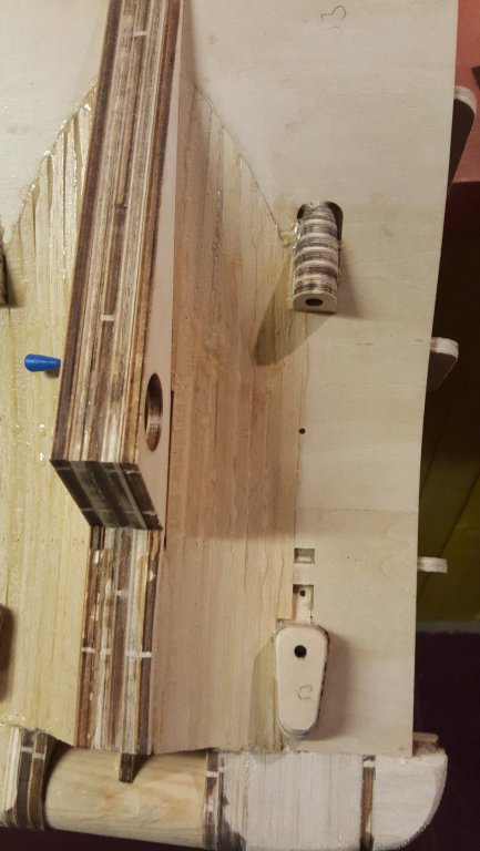
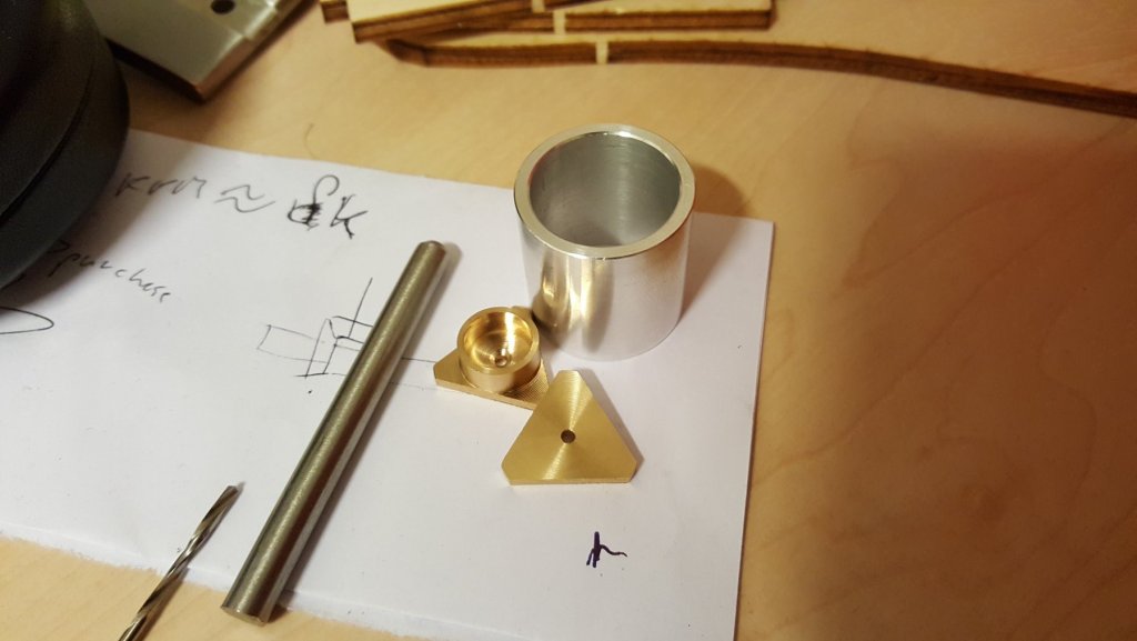
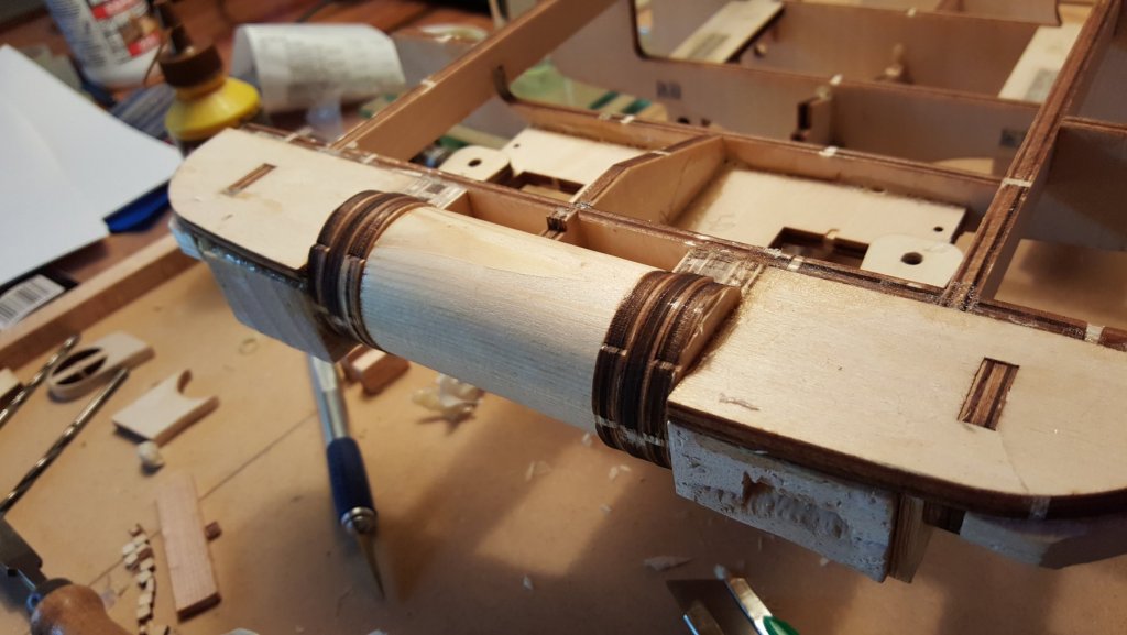
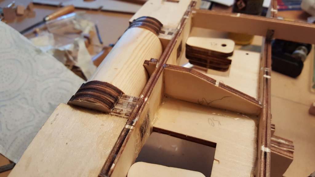
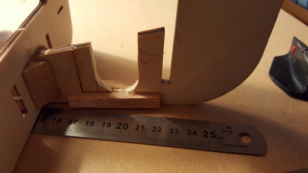
Thrusters: So recently we started working on the thrusters. The construction is of stator with worm bear of reduction 1:10 approximately, depends on the capabilities ofthe machune The first parts made are for the rear thruster, the body and the stator housing. The steel rod will be turned to the warm gear. Next thing I did, was repair the fallen off bow part of the keel. I added two pieces of hardwood by the sides to reinforce the construction again. Then the stern dowel followed. This piece creates a surface where, on the real ship, the towing line slides of deck. Next I moved to the central section of the hull, here I planned to create an anchor for the towing line so it would be possible for this ship to tow actual payload (I mean to use this ship for tug towing cups). The anchor is created from the rest of the hardwood dowel in a simple manner, the hardest part was to thought up a way, how to transfer the force to the keel without having the hull deform. Place for the towing line anchor. I deemed to put the anchor to the middle bulkhead (3rd on this picture) The anchor the the force transferring dowel beeing glued to place. Side view of the construction. I tried deforming it "by hand" it held steady for what i would dare to try, so I call it a success.


- 90 replies
-
- 3
-
-
- fairmount alpine
- billing boats
- (and 1 more)


.jpg.63bb1dce5be5964761f72061bcc726c9.jpg)