HOLIDAY DONATION DRIVE - SUPPORT MSW - DO YOUR PART TO KEEP THIS GREAT FORUM GOING!
×


rodgerdodger
-
Posts
95 -
Joined
-
Last visited
Content Type
Profiles
Forums
Gallery
Events
Everything posted by rodgerdodger
-
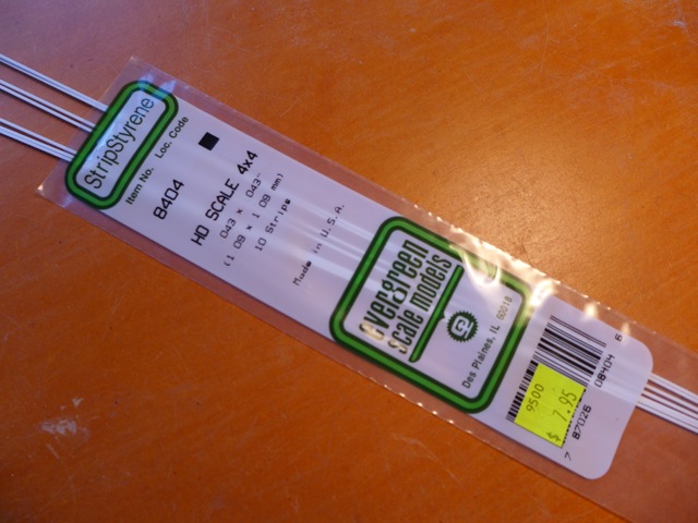
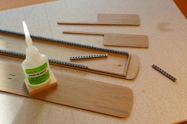
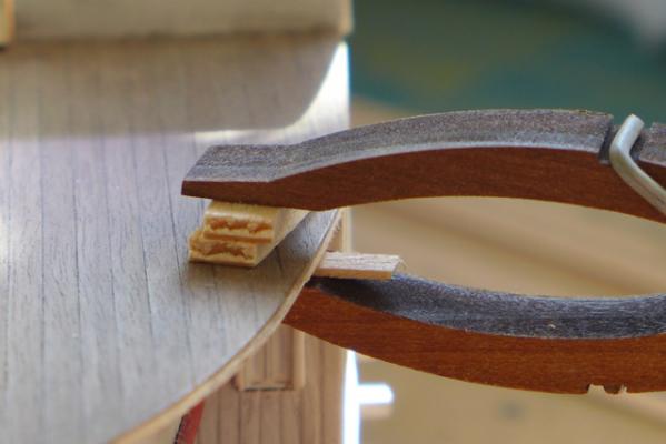
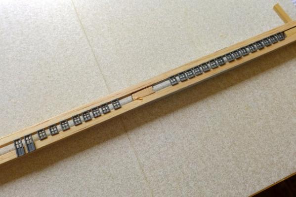
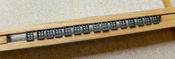
 Thanks Michael for your encouragement and the reference to the book of Mississippi paddle steamers. Very tempted to buy it. Also thanks to you Jim and Iran for the info on how you tackled the hand-rails. My compliments to you both for persevering with bending the 1mm sq timber strips provided with the kit. I am familiar with the technique of using ammonia (or window cleaner) to help with the bending but I honestly can’t believe you succeeded in using it. The bends are very tight in spots and the timber provided very brittle. Also it is significantly out of square. I am losing patience as the years pass and although I feel I am letting the side down I have decided to use the plastic strip in lieu of the timber. The material is described as styrene strip and is used in a variety of shapes and sizes by model train hobbyists in their dioramas etc. For those who want to take the easy route of using the styrene the following is a picture of the product.
-
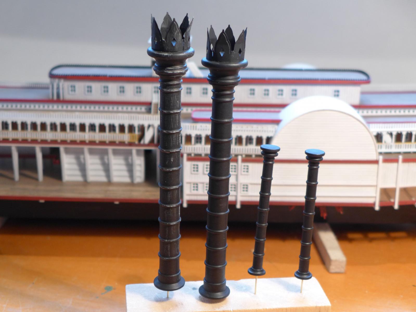
32 Smokestacks. The smokestacks provided with the kit are well made with no preparation necessary. The crowns at the top of the main stacks fitted with little trouble. The peaks of each crown are bent outwards for effect which requires some effort as you are having to bend a curved plate but the end result is ok. Painting smokestacks in progress and trying some weathering effect but will have to try something else as not happy with it.

- 94 replies
-
- 6
-

-
- robert e lee
- amati
- (and 1 more)
-
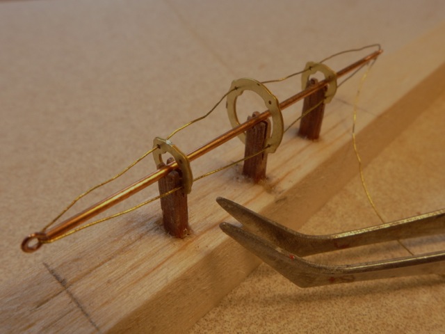
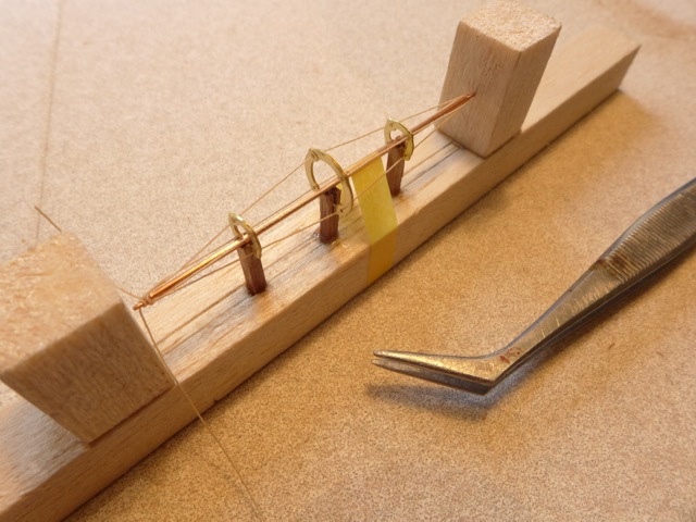
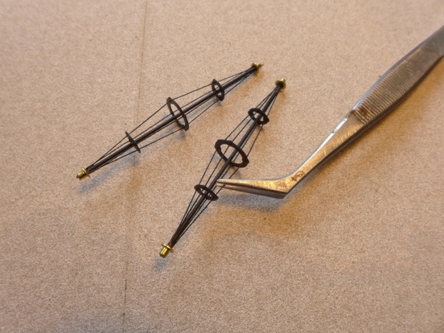
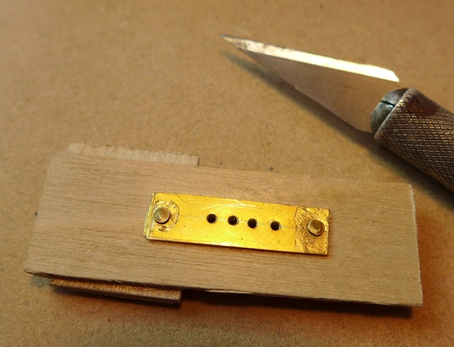
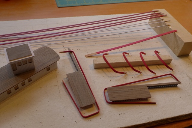
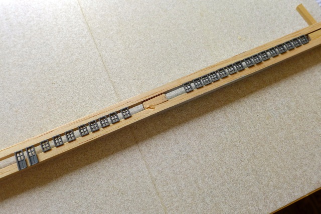
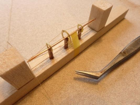
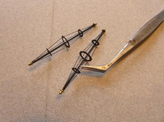
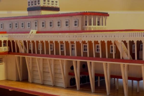
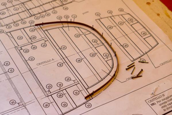
31 Smokestack Braces. If you haven’t already been driven round the bend with the railing and decoration details then working on the smokestack braces will get you there. Step one is to cut a length of 1mm tubing to fit the distance between the two smokestacks when erected. The length has to allow for the end of the tube to fit into holes that have to be drilled in the sides of the smokestack. Eyebolts are then glued into each end of the tube. (The eyebolts supplied with the kit are the smallest and neatest I have seen in any kit). I couldn’t see any way of assembling the braces without using a jig to hold everything in place. The following photo shows my first attempt at a jig made up from three pieces of 2mm sq timber set into a balsa base. Each timber ‘post’ is slotted to fix the three photo-etched spacer-rings (no idea of the correct term) in position. Then somehow you are meant to thread a thin brass wire supplied with the kit through the eyebolts at the end of the tube and back and forth through small holes drilled in the spacer-rings. No way could I prevent the wire from bending as I threaded it through the holes and it was impossible to put any tension in the wire to straighten it out without the whole assembly collapsing. After a couple of tries I gave up and decided that I would use 0.1mm rigging thread that I had from a previous model instead of the wire. The next photo shows a new jig (a bit more carefully made than the first) and the task of weaving the thread back and forth underway. The tube has been taped down to help hold it in position during the process. After completing the threading I used CA to fix the thread to each spacer-ring. To reduce the possibility of the thread ‘sagging’ when painted I gave it a coat of dope. When dry I removed the assembly from the jig (carefully!) and gave it a coat of black paint. Two smokestack braces down and one to go.

- 94 replies
-
- 6
-
-
- robert e lee
- amati
- (and 1 more)
-
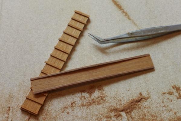
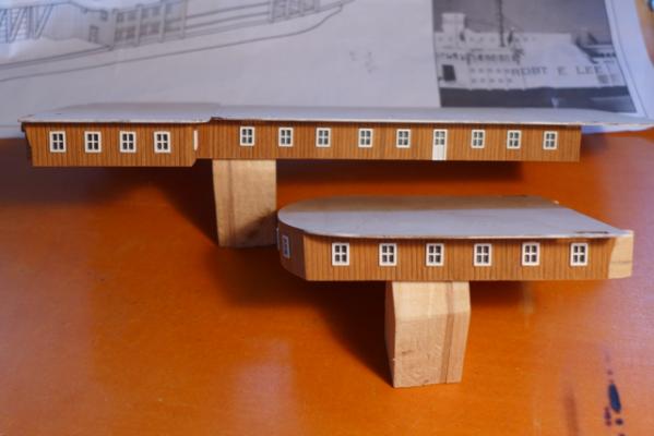
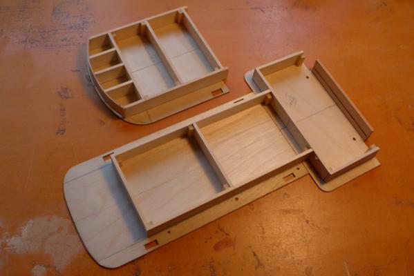
29 Gangways. While proceeding with the slow task of completing the railing posts and railings, and wanting to put off the installation of the handrail trims for as long as I can, I have branched off and commenced other stages of the model for a bit of light relief. The gangways have been completed without any dramas – nice change to be working with timber again. The two gangways under construction.
- 94 replies
-
- 2
-
-
- robert e lee
- amati
- (and 1 more)
-
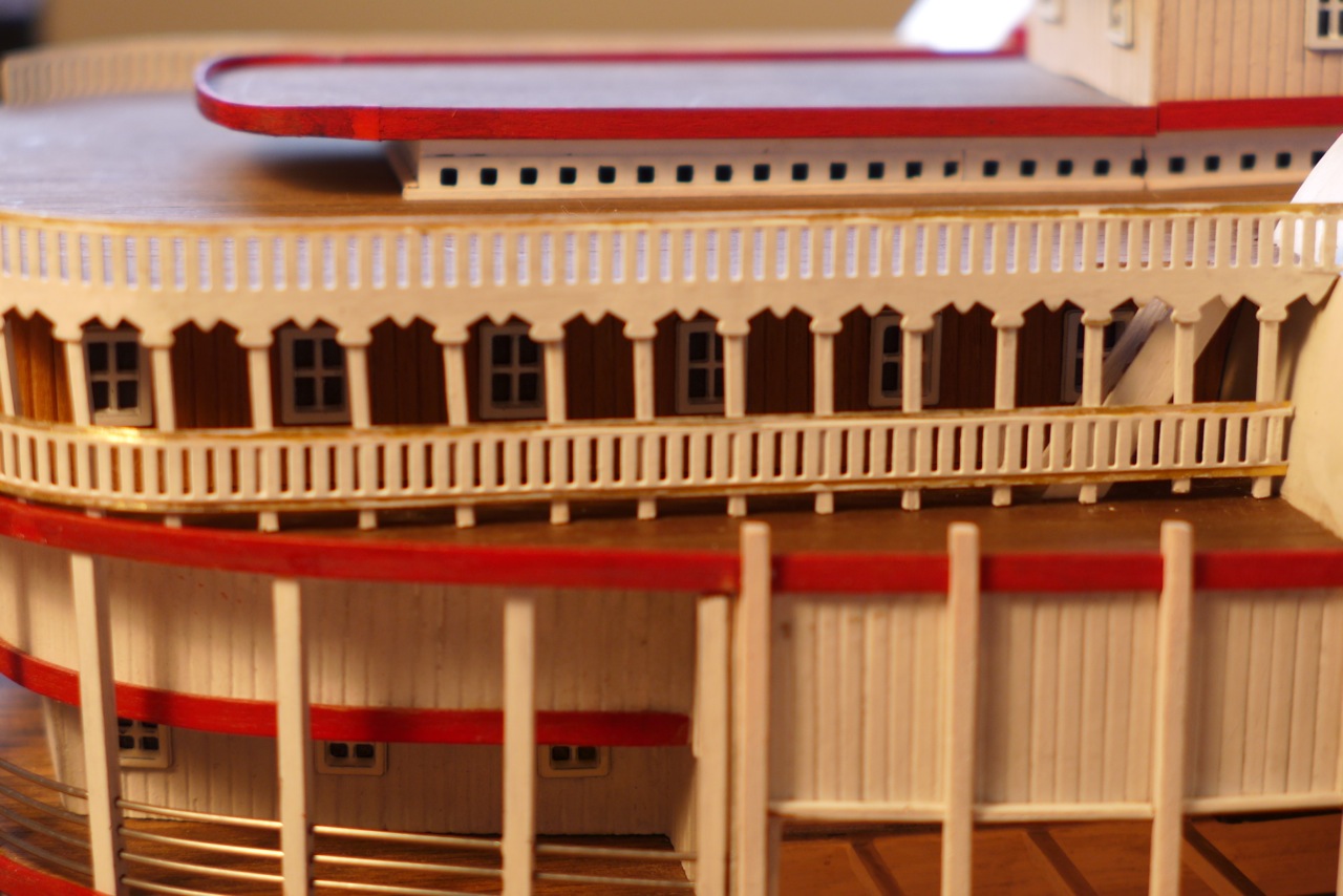
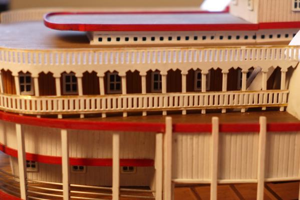
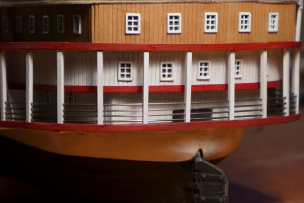
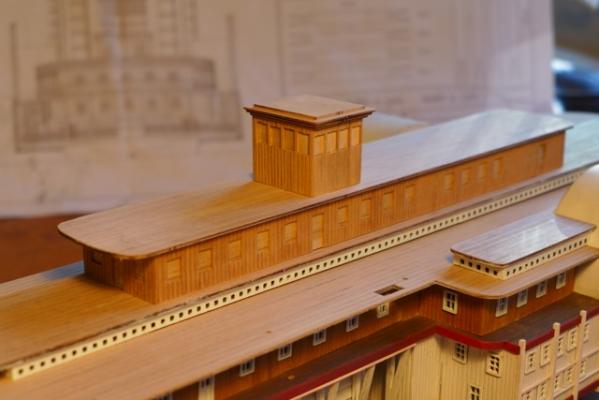
Thanks Iran and Michael for you comments. Iran, I am dreading working on the timber strips to the railings and would like to know how you, and Jim (aka Script), tackled them. The 1mm sq timber provided is too out of square for this application and far too brittle to tackle the tight bends. I am seriously thinking about using the 1mm sq plastic strip I used on the paddlewheel housings. In the meantime, having a closer look at the photo I posted before heading off for some R&R I could see that when you line up the posts with the window frames behind, they are clearly leaning out and out-of-plumb. Close-up photo shots highlight the smallest of faults of course but I couldn’t blame lens distortion this time so feeling refreshed from my break I decided to refit them. The solution was a 1mm packer at the top of the post behind the upper decoration. How this came about I am not at all sure. It could be the deck panels edges were not aligned correctly plus the lower deck edging having a slight lean inwards. However it illustrates how accuracy is an issue with this model if you want everything to line up correctly. Fortunately the posts on the port side are true and plumb. Posts before refit. Posts after refit. Not 100% but better than before.
- 94 replies
-
- 4
-
-
- robert e lee
- amati
- (and 1 more)
-
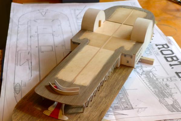
This is a progress shot before I head off for some R&R. During any build there comes a time when the pleasure of the build becomes a bit of a slog and I have reached that stage with this model. Even the smallest of misalignments between decks edges etc are starting to show up as the decorations and railings are installed and I don't have the persistence right now to correct them. So a bit of R&R is in order. Will give me a chance to think about how on earth I am going to fix the 1mm sq trims to the decorations and railings!
- 94 replies
-
- 7
-
-
- robert e lee
- amati
- (and 1 more)
-
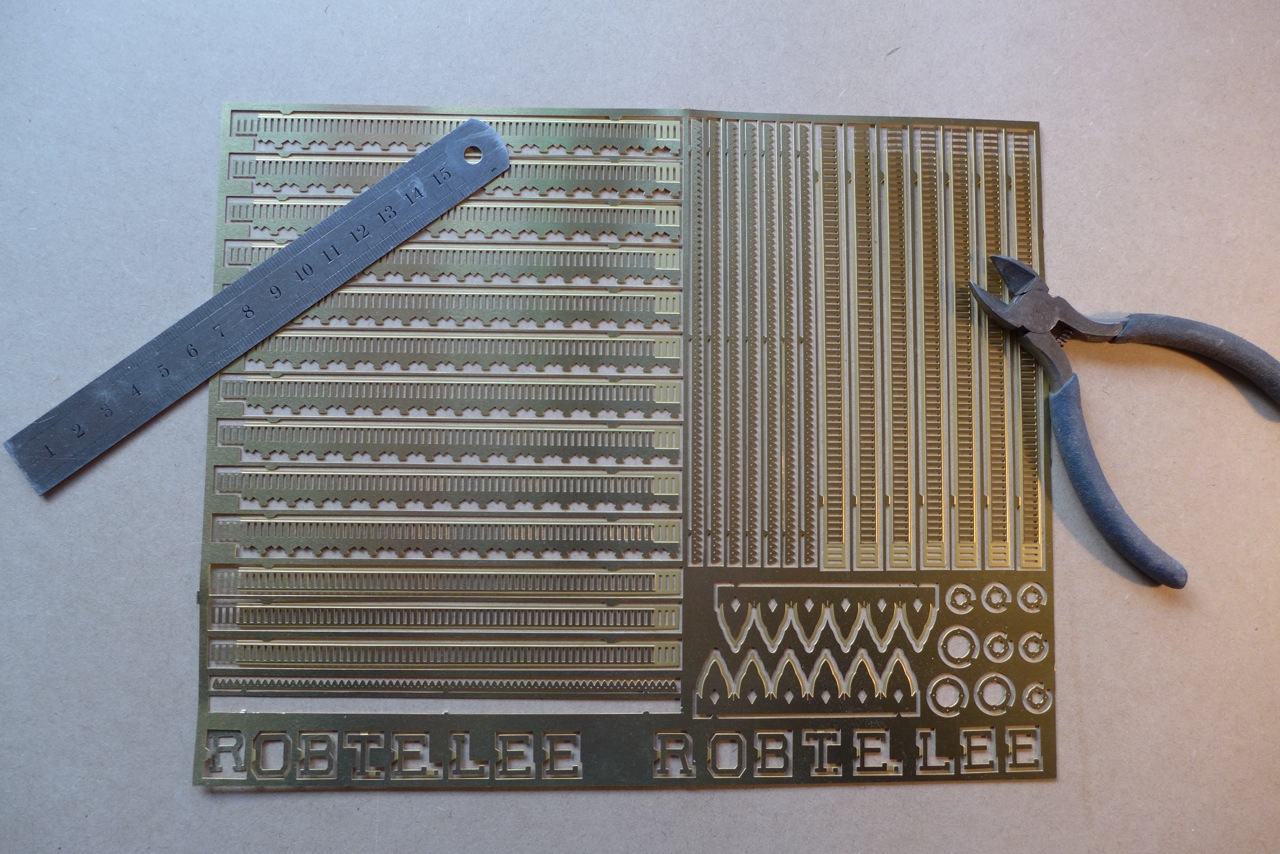
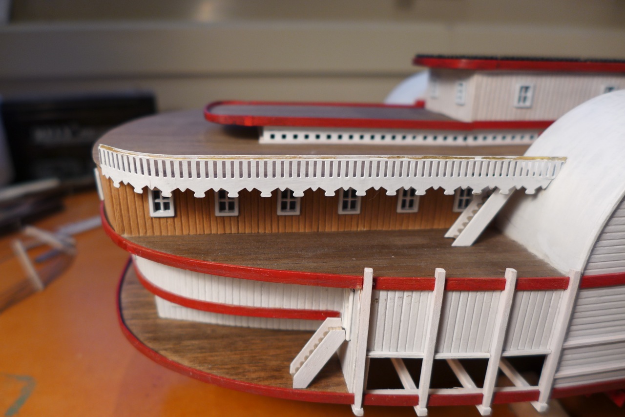
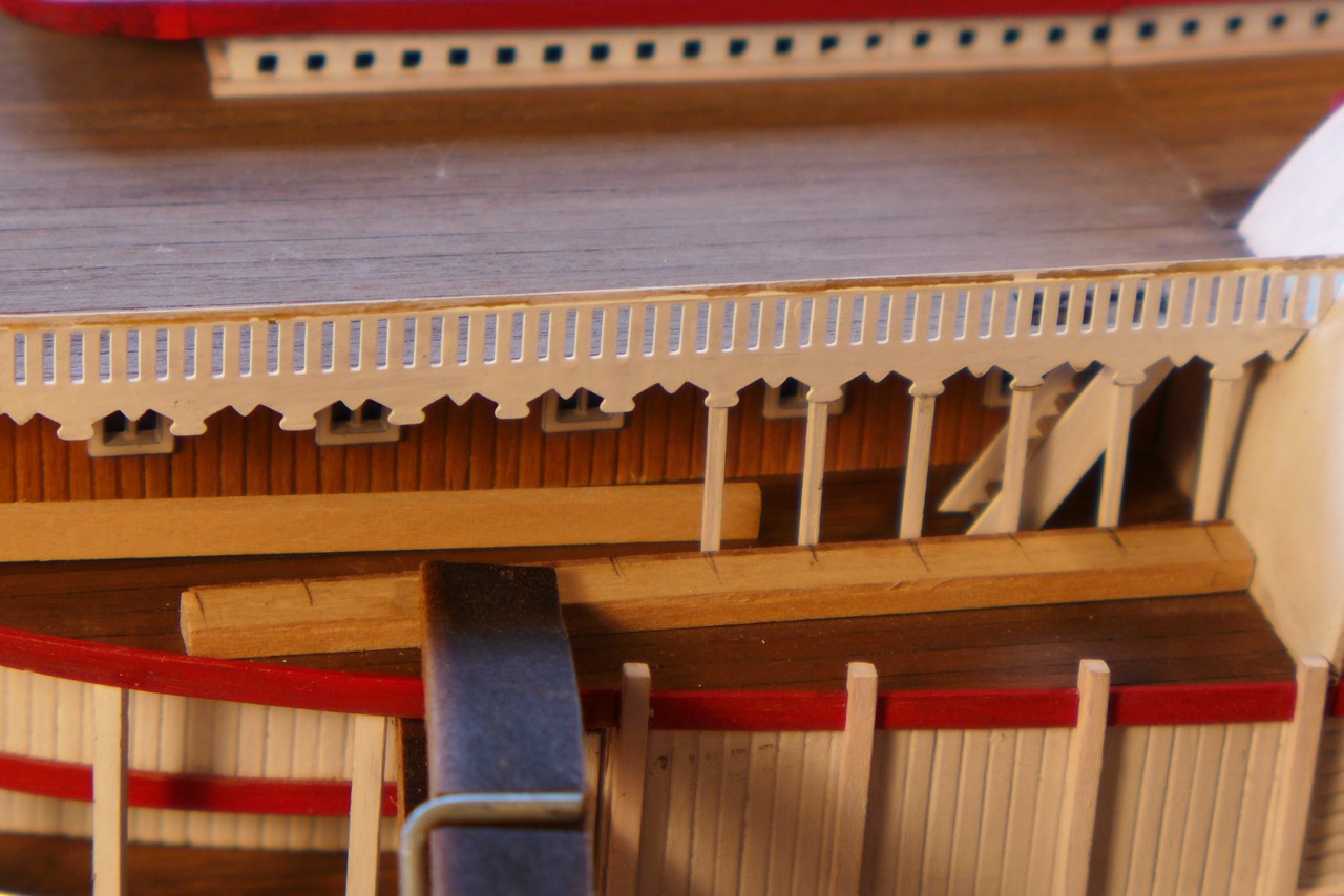
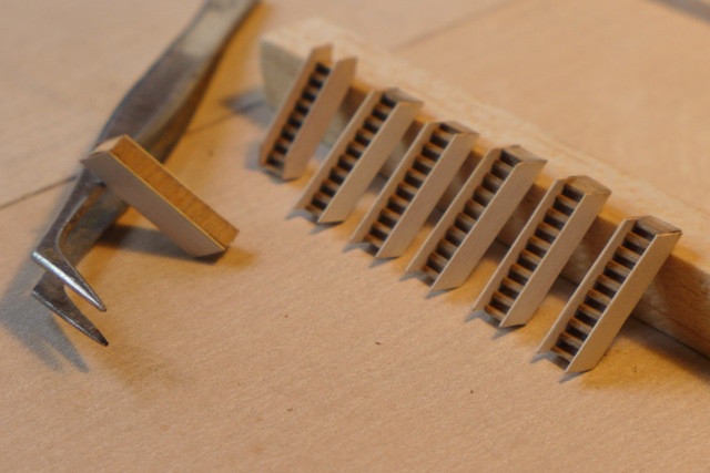
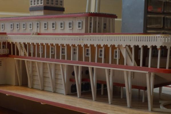
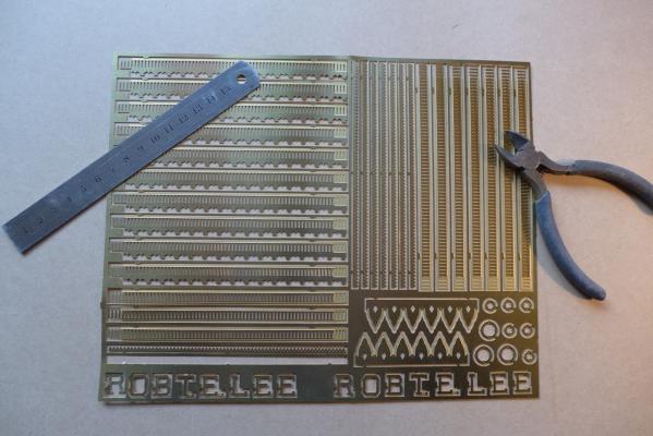
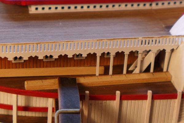
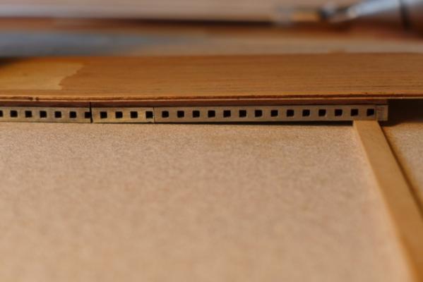
28 Railings and Decorations. The railings and decorations are made from photo-etched brass strip and supplied in a single sheet. Well made and detailed. Firstly I thoroughly sanded each side of the sheet before separating the components for convenience. I found the sanding was sufficient to achieve a good bond for the paint (flat white enamel) although it can chip if not handled carefully. I used a sharp chisel to separate the components as access for a cutter was difficult. Shaping each component to the required curve was quite straightforward. Each component is cut to length, curved if required and then painted before fixing. The procedure for installing the railings and decorations is illustrated in the following photos. Firstly the combined railing and decoration is fixed to the upper deck. A groove at the rear of the railing/decoration helps to located it very nicely on the edge of the deck. The next step is to install the 1mm sq railing columns. This proved to be quite difficult and frustrating requiring a steady hand and patience that is in short supply these days. To help I clamped a timber strip to the deck to provide a stopper for the bottom of the post. Using tweezers I maneuvered each column into place and when in the correct location I used a strip of timber behind the column to hold it in position as I released the tweezers. During this operation too often the column would flick into the distance like a twiddly wink and the hunt was on to find it. The bottom rail is then glued into position and I used 2mm sq timber spacers off the deck to be sure it was set level. This is not a very flattering photo as the columns appear out of plumb but that is largely camera lens distortion. The railings/decorations and posts are held on with spots of medium CA glue, all very delicate and not particularly substantial. One inadvertent knock and all will fall down.

- 94 replies
-
- 6
-
-
- robert e lee
- amati
- (and 1 more)
-
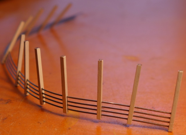
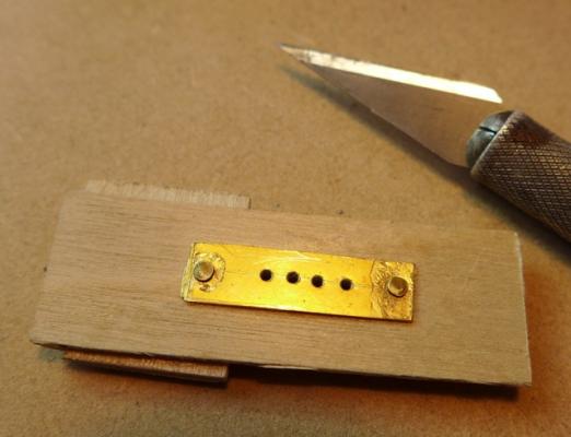
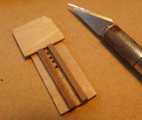
You are spot on ir3, accuracy is the key with this model and I will have a bit to say about this when I finally review the model, if I get there that is. The hull was solid and very accurate - no twists or bends, but I am not sure what the material was - some form compressed wood particles I think. Interesting you should mention the railings - that was the next stage in my log. 27 Rear Railing. The wires provided for the rear railing are 1mm dia and the railing posts cut from 2x2mm timber. As the posts have to be vertical and the rails are parallel to an inclined deck some tolerance is required in the hole drilled in the rail posts for the rails. A hole greater than 1mm drilled in the 2x2mm posts to suit the wire provided I felt did not leave enough room for error. I decided to ditch the wire provided and I obtained wire a gauge smaller. Unfortunately brass wire was not available so I used piano wire that made life even more difficult as it turned out. However I persevered and completed the assembly and the result is ok but I would not recommend using piano wire to others. Firstly the rail posts had to be cut very accurately and trial fitted before drilling. Needless to say they were not precisely the same length from one side of the deck to the other. To drill the holes for the rails I made a template from a scrap piece of brass sheet with the holes accurately drilled, glued and pinned it to a scrap piece of ply and built a jig on the reverse side to locate the post while drilling. I bent the rails as close as I could to the radius of the stern of the deck by twisting the four rails in a bunch around a large diameter dowel. A bit hit-and-miss but I achieved enough bend in the wires to take the spring out of them before fixing. I then threaded the 12 columns onto the wires. I now had a highly articulated assembly that was very difficult to maneuver and wouldn’t stay in one place for any length of time. Instead of drilling into the rear cabin wall to locate the rails I made an additional post and glued it to the end of the rails while trial fitting onto the model which made the assembly a little more stable. All a bit tricky. The post to the right in the above picture has been glued to the rails to give the assembly some stability. The first step in fixing the post and rails in position was to glue this post to the rear of the cabin. Then each post is progressively located in position around the curve of the deck stern. Gluing the posts in place is made difficult by the deck edge board that prevents the posts being slid into place. My solution was to delicately place a drop of thin CA at the base of the post, using a thin tube supplied with the CA for getting into tight corners. After all the posts were in position I cut the rails to the correct length at the free end and glued on another post which in turn was glued to the cabin wall. It was impractical to glue the top of the posts to the underside of the upper deck, so I used thin CA to glue the rails to each post. The end result is that the rails are holding up the posts rather than the posts holding up the rails! The end result looks ok but it was a battle to achieve. It took a lot of pushing and pulling to get everything into the right spot before fixing in place and there will be a need for some touch up at the end of the project. I am not sure if I will paint the rails - will wait and see. Not a very pretty method of building this stage but I can’t think of a better way at the moment. I apologise for the quality of my pictures but I would rather spend time on the model rather than time finessing the pictures.

- 94 replies
-
- 3
-
-
- robert e lee
- amati
- (and 1 more)
-
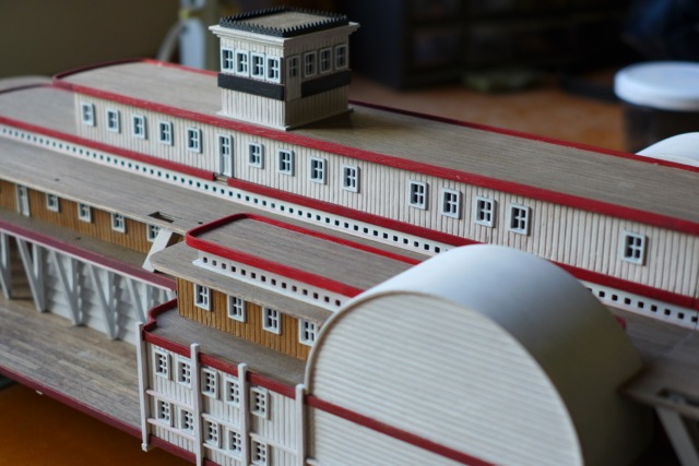
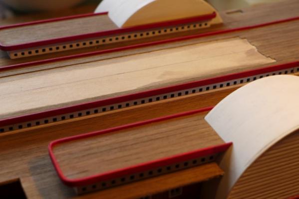
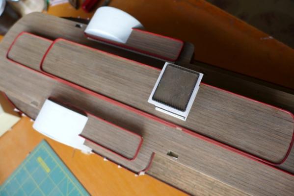
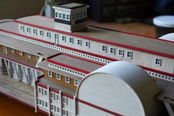
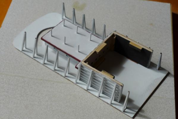
Good luck with your build Gerry and I look forward to seeing some progress shots. I have moved on with the installation of the skylights and cabins M & N but before doing so I had to prepare the edge strips and trims. As with any painted model various items have to be painted before gluing in place, rather than painting when fixed, to get the best result. The following picture shows the edge strips and trims during the painting process. There was no way I could bend a 3mm x 1mm strip around the tight curves so they were made from laminated 3mm x 0.5 strips (not provided with kit). The following picture shows the skylights in position and the 1mm sq white edge trim that goes around the perimeter of the skylights. I had better luck with the ‘staining’ of the three upper decks including the skylight decks. The next picture shows a more uniform colour and match between the decks. Unfortunately I was'nt so lucky with the first deck as previously explained but I hope that will be largely disguised with deck furniture, cargo bales etc. The next photo shows cabins M and N in position and overall progress to date. It does not show up that well in the photos but the ‘weathering’ of the model has been a blessing in disguise. It means that the odd splinter in the wood or uneven paint surface doesn’t stand out as a piece of bad workmanship!! Except for the installation of stairs to Cabins M & N I have completed up to stage 26 of the instructions.

- 94 replies
-
- 4
-
-
- robert e lee
- amati
- (and 1 more)
-
Thankyou Jim and David B for your encouragement - all helps to keep the motivation up! 23 & 24 Cabins M and N. Now completed without any new dramas and shown in position (but not yet fixed until painted). The skylights have been painted (it took four thin coats to get a satisfactory cover) and the deck planking completed on the 3rd deck, the skylights and cabin M. The next step is to ‘stain’ all these decks at the same time and hopefully achieve a uniform finish between them. Then it is a matter of painting the Cabins M and N and fixing them all in position. But I must remember to add the edging strips to the skylights and cabin M before fixing in place to make life a bit easier. Getting there!
- 94 replies
-
- 5
-
-
- robert e lee
- amati
- (and 1 more)
-
22, 22a & 22b Skylights on the 4th Deck (I think this should read 3rd deck). Before planking the third deck I decided to assemble the skylights to be able to mark out the area for the 3rd deck planking more accurately. Firstly I planked the ply rooves of the central skylight and two side skylights. The actual skylights are lead alloy castings – well made and requiring very little work to clean them up. The key is to carefully plan the layout of the skylight strips. Cutting of the strips is required at the corners and you have to keep an eye on which end of the strip you cut. Once the skylights have been accurately laid out the position of the 2x2 strip can be correctly located on the underside of the skylight roof, to which the skylights are then glued using medium CA. The photo illustrates progress on the three skylights. The central skylight goes across the joint between the central cabin and cabin H, and cabin H is on an incline. The instructions do not describe how to cater for this. I decided to cut through the skylight at the joint so that the skylight will sit neatly on the deck fore and aft of the joint as illustrated in the following photo.
- 94 replies
-
- 1
-
-
- robert e lee
- amati
- (and 1 more)
-
21 External Staircases These are made from preformed stair-flights that makes the task much easier although the tweezers still come in handy. External staircases under construction.

- 94 replies
-
- 5
-
-
- robert e lee
- amati
- (and 1 more)
-
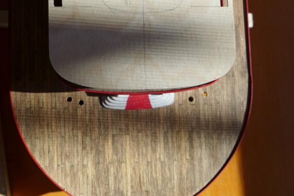
Before putting in place Cabins H & I, I decided to drill the 1st deck at the location of the masts in front of the main staircase as access would be difficult later. I used the deck plans to locate the position for drilling and, guess what, at 10cm spacing as per the drawing they miss the hull and go through the underside decking. As the masts are free standing I decided it was necessary to seat them in the hull and re-drilled the holes at 90mm centres. So I have a couple of spare holes that will require a coil of rope or similar to cover them. Anybody following this log one day with their build - beware!
- 94 replies
-
- 2
-
-
- robert e lee
- amati
- (and 1 more)
-
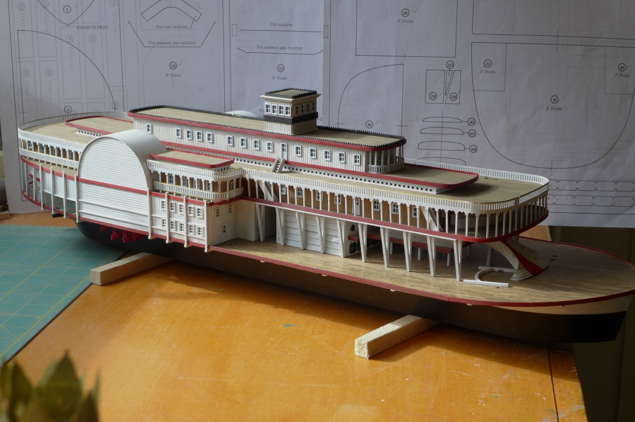
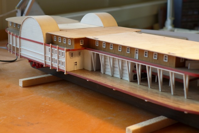
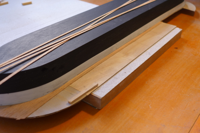
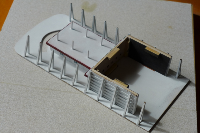
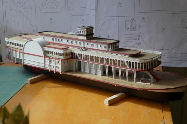
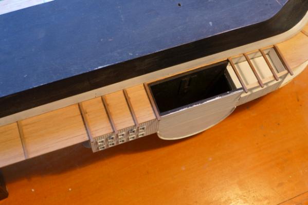
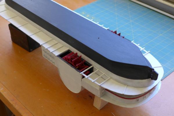
15 Finishing the first deck. The edging to the first deck and second deck is now completed together with the vertical ‘reinforcements’ and horizontal strips in the area of the paddlewheel housing. This is how the model now looks at the completion of stage 20 with cabins H & I in place ready for decking level 3. Note that the upper horizontal white strip on the paddlewheel housing does not line up with the horizontal strip to the rear of the housing. Oops! This is because the line of the upper white strip is governed by the position of the windows on cabin E. I used the cabin elevation on the plans to set out the windows that was obviously incorrect and I did not foresee this problem. Needless to say the instructions don’t mention it. I don’t think the error requires any drastic corrective action. While I think of it you will see that I fixed some 'skis' to the underside of the hull before I flipped it over when I had completed the underside planking. The skis are helpful in setting the model up at an angle when fixing edge strips etc and when I get to fixing the balustrades at the upper levels.

- 94 replies
-
- 5
-
-
- robert e lee
- amati
- (and 1 more)
-
Setting flags - which way does the wind blow?
rodgerdodger replied to rodgerdodger's topic in Masting, rigging and sails
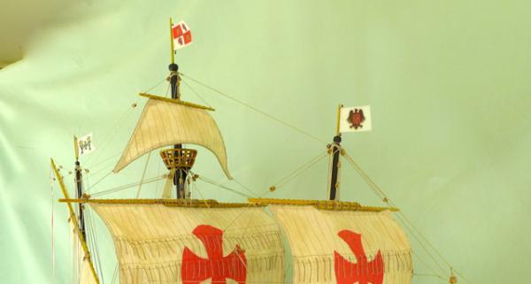
I realise from the responses that my introductory comments were too general. I should have realised they apply to a square rigged ship sailing down wind with the yard arms square to the axis of the ship, as is the case with most ship models. With other rigs there are far more solutions. The reason I brought it up is that there are some inconsistencies in models as illustrated in the following picture of La Couronne taken from the internet.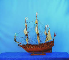
-
Setting Flags My young granddaughter was looking at a model that I had recently completed. She pointed to the flags and said in a very sweet voice “Grandpa – the flags are pointing in the wrong direction”. It made me think as to why I had set the flags in the way I had and what was the correct solution. I can’t find any comment on this matter in MSW so I thought I would get the discussion going. The flags on my model were pointing to the bow of the ship and in her mind they should be pointing to the stern. Her reasoning was that when she went riding on her scooter her hair was blown behind and not in front of her face. So in her mind if a ship is heading forward in the open sea the wind would blow the flags backwards. I tried to explain that even under full sail the wind is blowing faster than the speed of the ship moving through the water. As the wind is blowing from the rear of the ship then the flags would be pointing forward. From this I conclude that when model ships are fully rigged, with sails, the flags should be set pointing to the bow. Especially so when the sails on the model are bellowed. (Since this photo was taken I have worked on the flags so that they don’t look so new and drape a little more naturally. However they still point to the bow.) However when a ship is moored at anchor, with no sails set, the flags should be set pointing to the stern. This is based on the fact that the ship will set with the bow pointing into the wind (assuming the wind is blowing). So my conclusion is that any model ship that is not rigged with sails should have the flags set pointing to the stern of the ship. When a ship is moored at a wharf then the flags could fly in any direction – wherever the wind might be coming from. So you have to decide whether your ship model is moored at anchor or dockside and set the flags accordingly! Flags do add a bit of colour and interest to models but I suspect that flags would not be hoisted when under full sale and not when moored even except in special situations. I would appreciate any comment from someone with more nautical knowledge than I have on this. PS I am going to have to revisit a couple of models and reset the flags that don’t comply with the above, dammit. Plus I hope my granddaughter doesn’t have any more clever questions!
-
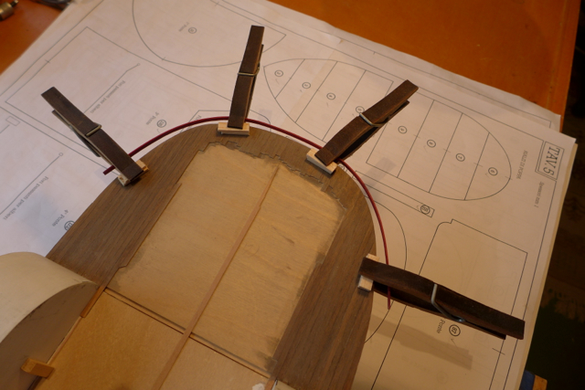
Thankyou Wacko Joe and my 'likers' for hanging on with my log. The trap with these logs is that once you start I feel you have to keep it going despite the occasional urge to down tools and take up golf or something! So I can feel the pressure is on with everyone looking over my shoulder so-to speak. I am finding the model challenging for reasons that I will discuss later and full marks to you Jim (aka Script) for successfully completing your model. Completion for me seems a long way off right now. To continue: - Cabins H & I Cont’d. Theses cabins have now been fully planked and windows/doors inserted. The wall planking on this level is left au naturel, which saves some time, and finished with a coat of flat acrylic - clear. The completed cabins ready for fixing to the model. But before doing so I decided I would install the deck edge plank at the stern of Cabin H as once the cabin is installed it will be more difficult to fix it in the correct location. All of the decks require an edge plank formed from a 3mm x 1mm timber strip. The decks are only 1.5 – 2mm thick so it is essential to locate the edge strips accurately. I used clamps with small timber strips to provide a ‘landing’ for the edge strip. Hard to explain and better illustrated in the following pictures. The small packers on the top of the deck are necessary to provide clearance for the edge strip. It was relatively easy to bend the strips by soaking in water then forming the curves by molding the strip into shape using my fingers. I then pinned the strip to a board to dry out using the deck plan for a guide as illustrated below that is a technique familiar to all modelers I am sure. When dry the edge strip was then painted before fixing. The photo shows the edge decking in position, threaded through the clamps, ready to be glued to the deck. I used medium CA (carefully) to glue the edge strips in place. Despite the ‘landing’ strips I still had to be careful that the edge strip was correctly located on the edge of the deck due to the fact the strips are not always 100% straight. Having completed this piece of deck edging I have decided to proceed with all the deck edging now, plus the other items mentioned in Item 16 in the instruction manual. Very fiddly stuff so it might be a while before you hear from me again!

- 94 replies
-
- 6
-
-
- robert e lee
- amati
- (and 1 more)
-
18 & 19 Cabins H & I. To set out the cabin walls for Cabin I it is important to note that the forward edge of deck piece 171 has to be vertically above the forward edge of deck piece 175, other wise there will be problems when it comes to installing the balustrade later. To set out the walls of Cabin H note that the rear edge of deck piece 161 has to be vertically above the rear edge of deck piece 17. Also the rear wall of the Cabin has to be just 1mm back from the rear edge of deck piece 161 (1mm to allow for the cabin wall planking). The deck pieces 161 and 172 had to be rebated a little to fit up to the paddlewheel housings. Having completed the cabins H & I the area for deck planking on the 2nd deck can be marked and the decking completed. The second deck with planking completed and stair balustrades in place before the cabins H & I are installed.
- 94 replies
-
- 4
-
-
- robert e lee
- amati
- (and 1 more)
-
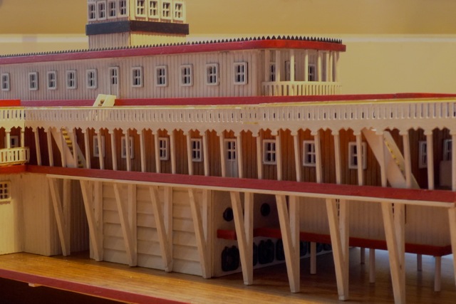
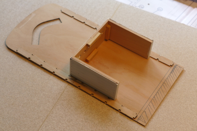
15 First Structure Assembly. With the main staircase in place the colonnade and cabins A, B, C, and E can be placed fixed in position onto the first deck. The instructions advise ‘consult the designs and proceed with great care’. Not at all helpful! The main thing is to keep every thing square, on centerline and make sure all components make full contact with the deck. (Missed out on taking a picture at this point.) 16 Finishing the first deck. I decided to skip this stage as fixing the edge strip and other items can be done later. 17 Lower part (i.e. underside) First Deck. This stage is illustrated in the instructions, not on the drawings. I started planking the underside of the first deck after planking the topside. My thinking was to make the deck sheet stiffer as the overhangs were flapping in the breeze so to speak being only 1mm thick. I discovered planking the underside did not help the stiffness and furthermore the ‘reinforcing cross pieces’ cannot be correctly located until the first deck structures are in place. Note that the drawing shows four ‘reinforcing cross pieces’ aft of the paddlewheel housing but omits the four cross pieces fore of the housing. These can be seen in the photo of the completed boat on the box lid. Starting the planking before the first deck cabins are in place. Four reinforcing cross pieces fore and aft of the paddlewheel housing. The four forward cross pieces are located to suit the window layout on cabin E. Underside of deck completed and painted with paddlewheels in place. All ready to be turned over and never to be seen again unless you view the boat on your hands and knees!

- 94 replies
-
- 4
-
-
- robert e lee
- amati
- (and 1 more)
-
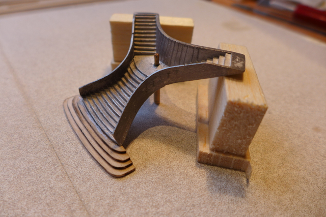
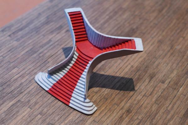
14. Main Staircase Before fixing the colonnade to the deck I decided to work on the main staircase. I suspected that once the colonnade was in place assembling and fixing the staircase would be problematic. The main staircase is a lead alloy casting – not particularly well made. I started by filing off the faux planking from the balustrades as it was not well done and wouldn’t be missed. Further filing was necessary to ensure the bottom step was parallel with the top landings so that the stairs when installed sat correctly upright plus other cosmetic work. To be able to glue the four lower steps onto the casting correctly I decided to install the column under the middle landing first. It took some measurements and some trial and error to get the right length for the column and I drilled a hole thro’ the middle landing to make the column more stable. I then glued the casting to the steps using a jig to hold the casting up at the same time checking that the top landings were level. It doesn’t help that the lower steps land on the section of foredeck that is inclined and they have to be slightly tapered on the underside to cope with this. Now that the main staircase is freestanding it can be located in the correct position on the main deck by temporarily putting the colonnade in place and marking the correct location for the staircase. Again a bit of trial and error to get it right. The main staircase in position ready for the colonnade to be placed over. As you can see I decided to give the staircase some red-carpet treatment.

- 94 replies
-
- 8
-
-
- robert e lee
- amati
- (and 1 more)
-
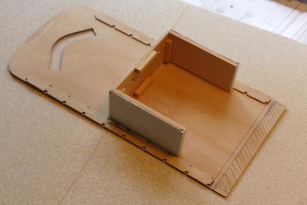
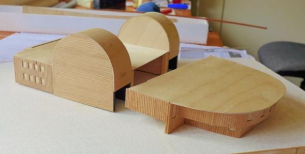
Colonnade cont’d. The Boiler Zone and Raised Cabin glued to the underside of the Colonnade ready to be landed on the main deck. A lot of checking and rechecking is required to be sure that the colonnade columns, the Boiler Zone and Raised Cabin columns sit neatly on the deck with no gaps. The tendency for the colonnade deck (115) to bend, especially due to the components being glued on just the underside, didn’t make it easy.
- 94 replies
-
- 6
-
-
- robert e lee
- amati
- (and 1 more)
-
In the meantime work has been progressing very slowly and tediously on the finishing of cabins A, B, C and E, F and G. With up to four coats on each area, waiting for each coat to dry, then the weathering (why am I bothering?), painting the windows, fixing them and so on. You can only do so much at time so it is a matter of popping in and out of the workroom when you can. Sadly it denies you of any excuse not to tackle those other jobs about the house. It is what you expect with models that have to be painted and finished as you progress but looking at the picture of the finished model I have to wonder if and when I will get there.
-
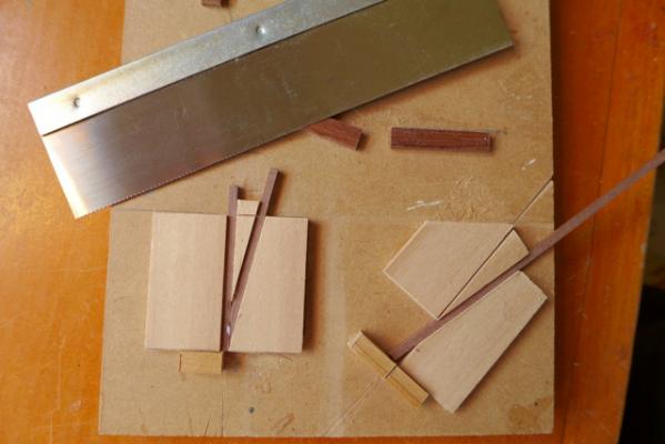
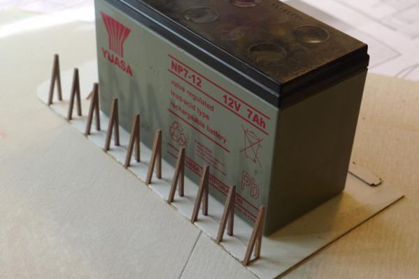
13. Colonnade When fixing the colonnade supports (items 134, 134) to the underside of the foredeck (115) note firstly that they are not symmetrical. The column spacing at one end is different to the other for some reason. The instructions do no give you any clue as to which way they should go so take your pick as long as the columns line up on opposite sides. Secondly the position of the supports should be determined relative to the location of the end of cabin E by marking on the underside of the foredeck the location of cabin E. The foredeck is a sheet of 1mm ply and naturally flexible. At all times during construction of the colonnade the sheet has to be flat to ensure that the columns etc., when in place, are vertical and square. Also accuracy in the build is essential to ensure that columns or cabin F or G are not dangling in the air when finally in place due to differences in the length of the columns and the depth of the cabins. The colonnade column supports being glued in place. This is when I discovered that the width of the boiler zone (cabin F) should not exceed 90mm. I was 1mm over as previously mentioned. Also the extent of cabin E is shown shaded View of the jigs used to construct the colonnade columns and cut the taper on the sloping leg of the column. Accuracy was essential here and despite taking care I found it necessary to bunch up the completed columns on a flat board and carefully sand them so that they all were the same length. Glueing the columns in position. For this task I used a 12v gel battery which served the dual purpose of keeping the deck sheet flat and providing a ‘wall’ against which I could place the columns and keep them vertical.
- 94 replies
-
- 7
-
-
- robert e lee
- amati
- (and 1 more)
-
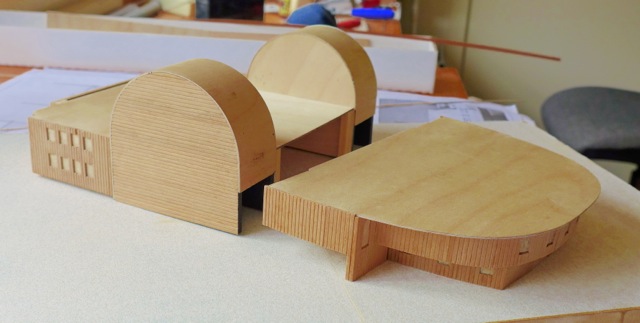
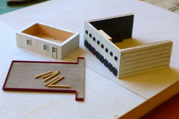
11, 12. Boiler Zone and Raised Cabin. These are straightforward to build and no further comment is required EXCEPT when building the Boiler Zone check that the width is under 90mm. It has to fit between the columns in the colonnade shown in section 13. I was one mm out and I had to take corrective action by cutting the front wall at the centre to shorten it and splice together again. Above is a picture of the completed Boiler Zone and Raised Cabin components ready for assembly. Note that painting is complete and windows and doors in place. Also note the splice in the centre of the Boiler Zone after reducing the width.
- 94 replies
-
- 4
-
-
- robert e lee
- amati
- (and 1 more)
-
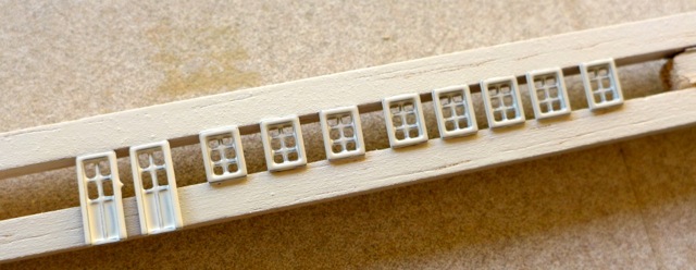
Painting and window/door installation. The instructions contain several pictures of the model during construction before any wall planking or paint is applied. This is obviously just for illustration purposes as it clear that the wall cladding and the painting has to be completed progressively before each level of cabins is fixed in place. It also seems advantageous to me to install the windows and doors progressively rather than fixing at a later stage. Fixing the wall planking I have already mentioned. Here are cabins A,B,C, and E with planking in place and ready for painting. It is always difficult to get good coverage with white paint. I tried sealing, then I tried priming but in the end it still required several coats before a satisfactory result was obtained. I used a flat enamel hobby paint and the coats had to be applied thinly otherwise the wall joints begins to disappear in the layers of paint. For weathering I applied a very weak solution of a grey water-based paint (that the kids use) that was quickly wiped off with a clean cloth. The effect is aided with the ribbing in the wall plankng and the result looks like a white painted boat that needs a coat of paint! Whether it is successful I will leave to others to judge. There are a load of lead cast windows and doors in the model (the don’t say how many in the parts list) – too many to paint one at a time. They are well made and only the odd one or two need filing to remove excess etc. I pickled them in vinegar as suggested in another section of MSW. I tried spraying them laid out on paper but found that the window openings clogged up as the paint puddled on the paper. Instead I made a simple rack from two square balsa beads, spaced at the correct distance to seat the windows. I sprayed two thin layers of paint using an off-the-shelf can of domestic spray paint. Edit 3/5/2014. There are two types of window on the model, 4 pane and 6 pane windows. Glaringly obvious when you see it but I didn't. Fortunately I correctly used the 6 pane windows on the lower cabins but the windows on the raised cabin should have been 4 pane for example. I don't think it will be a problem. The pilot's cabin will have to be all be 4 pane windows instead of 6 and the error will not be obvious - I hope! To fix the windows and doors I used a small dot of epoxy, hopefully sufficient to keep them in place. For a model of this scale it is important to have the windows as perfectly in line horizontally and vertically as possible. A 0.5 mm misalignment on the model would be equivalent to a 75mm misalignment full scale! As there is little clearance within the window cutout to maneuver the window for alignment, it is important to make the window cut-outs in the wall planking correctly aligned during the planking process. Easier said than done of course!

- 94 replies
-
- 6
-
-
- robert e lee
- amati
- (and 1 more)