HOLIDAY DONATION DRIVE - SUPPORT MSW - DO YOUR PART TO KEEP THIS GREAT FORUM GOING! (Only 13 donations so far - C'mon guys!)
×


rodgerdodger
-
Posts
95 -
Joined
-
Last visited
Content Type
Profiles
Forums
Gallery
Events
Everything posted by rodgerdodger
-
 I hope you will find the blog helpful Larry. If you haven't seen them there are excellent photos of the model, built by Jim (aka Script), in the Gallery of MSW. A good help to keep one motivated.
- 94 replies
-
- 1
-

-
- robert e lee
- amati
- (and 1 more)
-
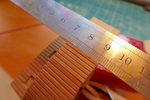
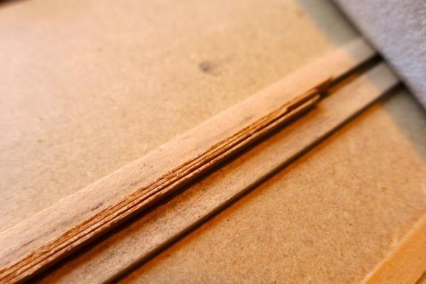
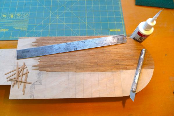
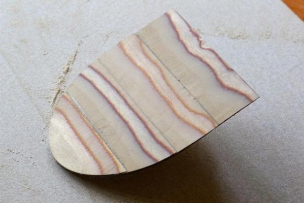
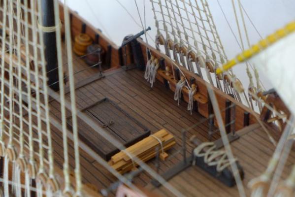
I wasn't happy using the plastic strip but I can't imagine using styrene David? 8 Decking. Before completed cabins can start to be placed on the deck, the deck has to be planked. The quality of the deck strips supplied is the first negative with the kit. The timber has a very coarse grain and is poorly cut. Good planking material has to have clean edges and a consistent width. The quality of the strip is illustrated in the following photo and I sanded the edges of the strips in batches of four to smooth the edges. However, to sand them to a 100% smooth finish meant that the width was reduced and the end result was that there were variations in width between strips – small but noticeable when you start laying out the deck. The strips were supplied 3mm wide which at a scale of 1:150 gives a full scale plank 450mm wide – i.e. too wide I guess to be to scale. I also decided to cut the strips into plank lengths of 60mm being 9m full scale. I have no idea if this is realistic or not. The end result is disappointing and just doesn’t look right to scale. I might have been better off simply laying the planks in continuous strips and not emphasizing the joints or plank lengths. I will consider this for the upper decks. Sanding the edge of the deck planks Deck planking in progress. Finishing the deck. To finish the deck I decided to treat it with the vinegar/steelwool solution described in the following link: - http://miniatures.about.com/od/miniaturebasics/f/vinegarwood.htm It is meant to give a natural aged timber look that is in keeping with the weathered look I intend for the model. It works well except that it is difficult to determine the end colour and I put on one too many coats of the solution and the colour was too dark. This meant sanding the deck back to bare timber and having another go with the solution. However the sanding wasn’t too successful and at the moment the deck looks like a patchwork quilt. I am still working on it. Maybe I shouldn’t be losing too much sleep over it as when completed there isn’t much deck exposed when all the cargo, ramps etc. are in place.
- 94 replies
-
- 1
-
-
- robert e lee
- amati
- (and 1 more)
-
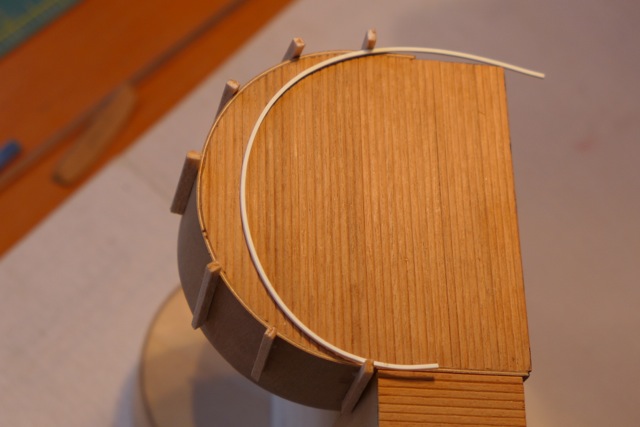
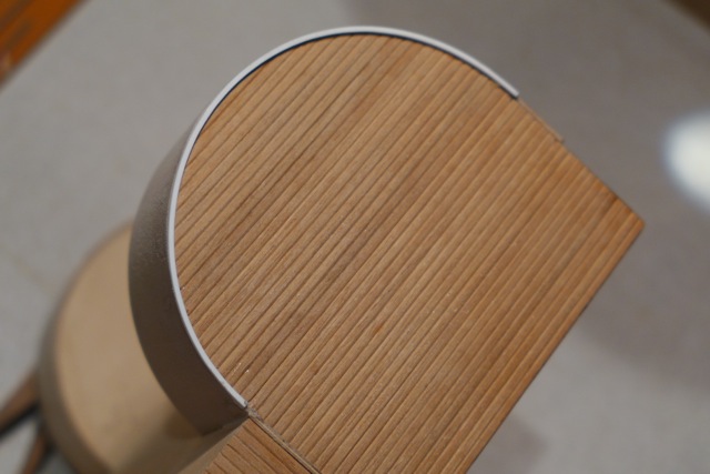
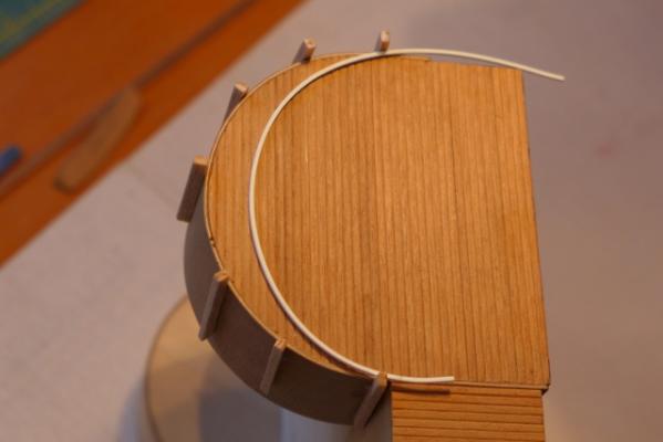
Trim to Paddlewheel housing A 1mm sq trim is detailed on the outer curved edge of the paddlewheel housing. There was no chance of bending the 1mm sq timber trim provided with the kit as it was far too brittle. Instead I cheated and used a length of 1mm sq plastic used in architectural models. Yes, I have sinned and used plastic on the model but as it is going to be painted nobody is going to notice. The plastic strip was easily prebent by hand. To fix it to the housing I spot glued a few strips of balsa around the curve to help with keeping the strip in position right on the edge of the housing. I used small dots of 5min epoxy and held the trim in place while the epoxy set. The trim and balsa strips in place ready for glueing. The trim glued in position.
- 94 replies
-
- 6
-
-
- robert e lee
- amati
- (and 1 more)
-
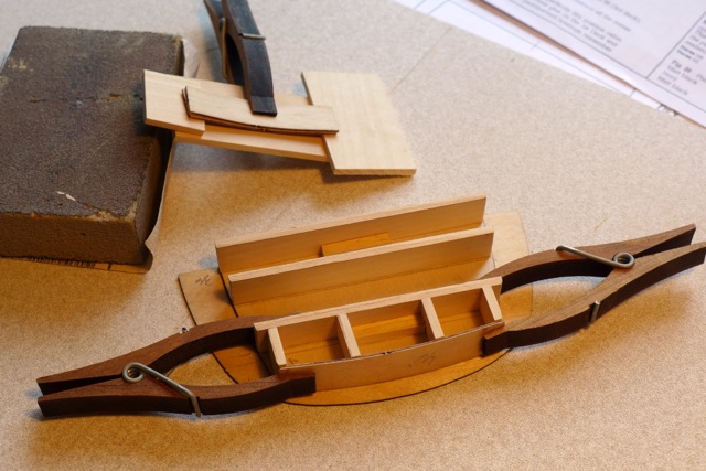
6a,b,c. Cabins A,B,C. Before starting on these cabins check that deck piece 17 matches with deck piece 16 and trim the edges if necessary. I didn’t and I had to make some changes when I was half way through cabin A. The width of deck piece 17 should also match up with the finished assembly of Cabin E plus paddlewheel housings. Note that figure 11 is confusing. It is drawn upside down and the tapers on pieces 48, 49 are in the wrong direction that had me guessing for a while. The assembly of these cabins is fairly straightforward. You can cut the walls to length using the dimensions from the drawings, or by marking out the walls on the deck pieces 17 and 36 and measuring accordingly which I found preferable. Note that the position of wall 18 (which is inclined with respect t deck 17 and perpendicular to the waterline) relative to the stern edge of deck 17 is critical. The stern wall of cabin B has to be a certain distance from the stern edge of deck 17 to provide space for the perimeter columns. I found that I had insufficient room for these columns and it required some repair work to fix it. Cabin B too close to edge of deck 17. More clearance after fix. The following pictures show the construction of the Cabins and no explanation is required. Cabin A Cabin C Building cabin B (Cabin C under)


- 94 replies
-
- 1
-
-
- robert e lee
- amati
- (and 1 more)
-
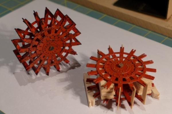
Hi Spud1. Good luck with your build and I sincerely hope you find the log useful as that is what these logs are all about. 7d. Paddlewheels. It seems odd building the paddlewheels at this stage but I guess that as it will be impossible to turn the model upside down as work progresses the wheels are better inserted in the housings sooner rather than later. The wheels are lead castings and good quality. I painted the castings before assembly. To assemble the wheels I used balsa spacer blocks between each side and simply held them as the spindle was inserted and glued in with epoxy. The length of the spindle is measured from the completed housing, and the width of the spacer was calculated allowing clearance for the paddles inside the housing etc. To make sure the sides were centred and square I epoxied in a few paddles at the same time, viewed it from the side, top etc., and that helped to check that all was correct. The wheels were rested on balsa packers while the epoxy set. One wheel completed, the second in progress. I have got some more work to do on the painting and weathering. A lot of effort for in item that is mostly hidden inside the housings!
- 94 replies
-
- 3
-
-
- robert e lee
- amati
- (and 1 more)
-
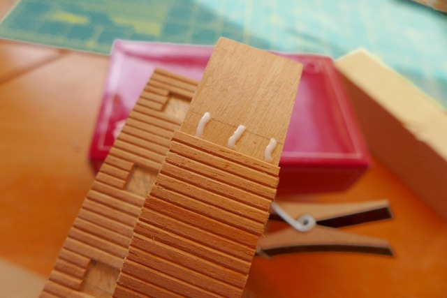
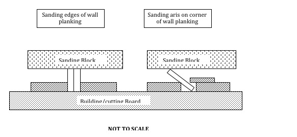
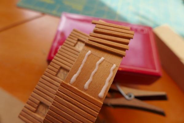
I am sure you realise that the log is just catching up with my progress David B. Unfortunately the build itself isn’t progressing that quickly. Wall planking. This is jumping ahead a bit but seeing that wall planking is necessary on the paddlewheel housings I thought it worthwhile to show the method I have used for preparing and fixing the planking. The wall planking is in 2mm x 1mm strips of walnut, I think. Firstly I lightly sand the sides of the strips to remove any rough edges using a jig on my building/cutting board from timber strips. (Excess decking strips from a previous model.) The instructions also recommend sanding the corners for effect and that seemed a good idea to me but very fiddly. I use another jig for this also made out of excess timber strips from another model. These jigs are illustrated in the next sketch – I hope you get the idea. This is not a method that produces a precise aris but it seems to produce a satisfactory result and some variation is not detrimental. The wall planking varies in lengths from 35mm down to 2-3mm (at windows and doors). Because of their small size it is impractical to apply glue to each plank. Instead I precut a number of planks, the number depending what part of the model I am working on. Using a glue dispenser with a fine nozzle I lay down 2-3 lines of glue ahead of the last fixed plank, and then place each pre-cut plank in place using tweezers. Then a straight edge is used to push the planks together before the glue sets to ensure the planks are in full contact with each other. Hopefully the following pictures help to explain this. By the way, you need a wet sponge on hand to wipe off any excess glue in the joints between the planks. Yes, you are right. It is fiddly and time consuming and I have a long way to go. I can place up to 12 planks at a time on a straight stretch before I start panicking about the glue setting. The thin lines of glue are more than adeqeuate to fix the panels. Working around the windows and doors is a bit slower of course.


- 94 replies
-
- 4
-
-
- robert e lee
- amati
- (and 1 more)
-
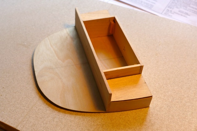
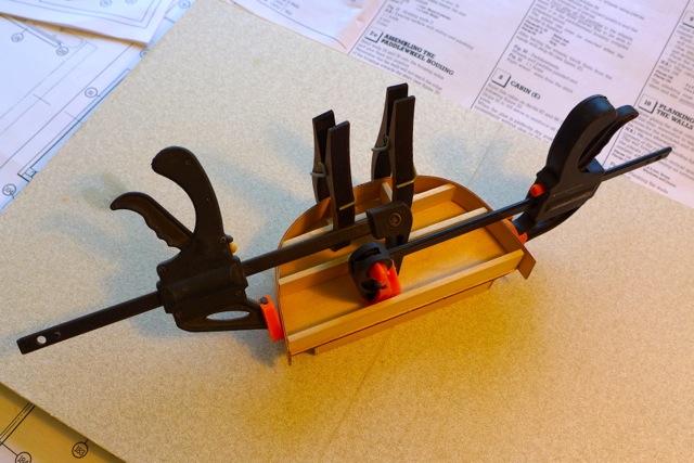
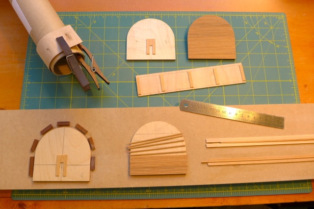
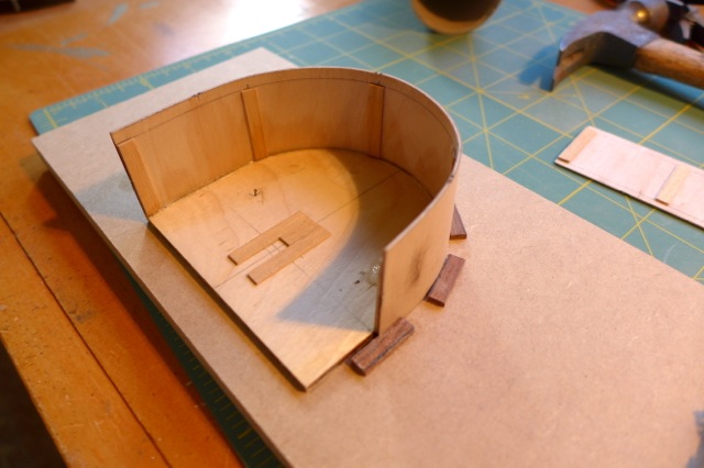
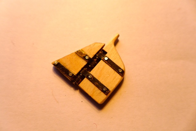
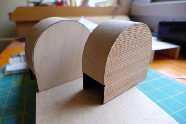
7a,b,c. Paddlewheel Housing. These are tricky little structures and need to be built accurately straight and square. I decided to build each housing in two stages. Firstly fixing the curved roof to the rear wall of the housing and then fixing the front wall. The alternative is to fix the curved roof to the front and rear wall at the same time. This was impractical without making a mould or similar to hold the walls firmly in position while fixing the roof. This picture shows my ‘cutting board’ with the profile of the curved roof set out using a wall panel as the template and timber strip off-cuts glued to the board. The roof sheet has the spacer timbers glued in place (important to make them the correct length and correct set-back from the edge of the sheet). Another roof sheet is bent around a tube after wetting to put some pre-set curve into the sheet. The wall planking is under way on the outer wall of the housing (refer following posting on preparing the wall planking). This photo shows the rear housing panel being glued to the roof sheet. The panel is used to push the roof sheet to the correct radius up against the timber off-cuts. A fair amount of pressure is needed to push the roof sheet firmly against the off-cuts while at the same time ensuring that the end of the roof sheet lined up with the bottom of the panel on one side, and that both components were pressed flat onto the board. When in the correct position the wall panel was nailed to the board. After patiently waiting for the glue to set I removed the assembly from the board praying that the glue worked. To be honest it took me a couple of tries to get it right. Fixing the outer panel is a piece of cake if stage one is completed successfully. The spacer strips on the inside of the roof sheet are helpful at this point to assist with aligning the face of the clad panel with the edge of the roof sheet.


- 94 replies
-
- 5
-
-
- robert e lee
- amati
- (and 1 more)
-
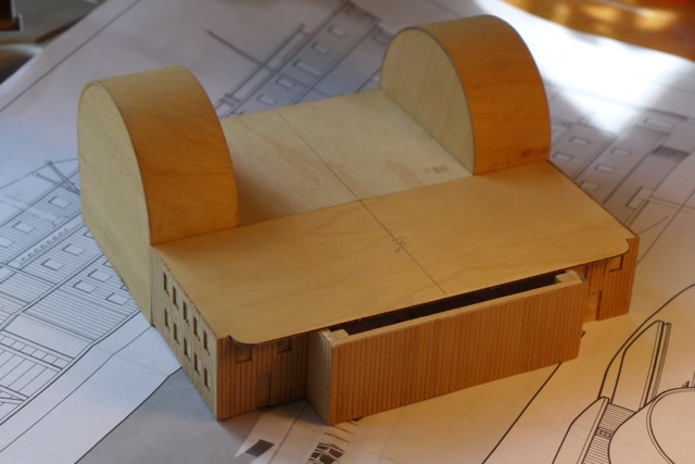
Fiddly is spot on and the worst is to come! View of completed Cabin E (after adding the paddlewheel housings and completion of the wall planking).

- 94 replies
-
- 3
-
-
- robert e lee
- amati
- (and 1 more)
-
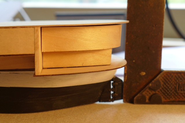
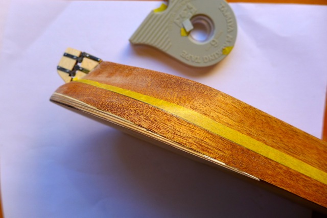
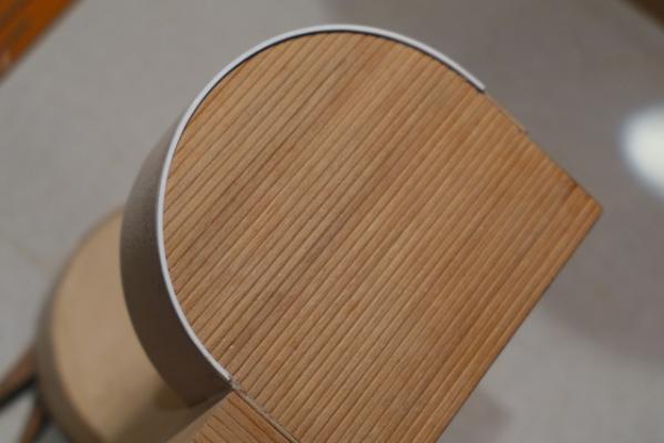
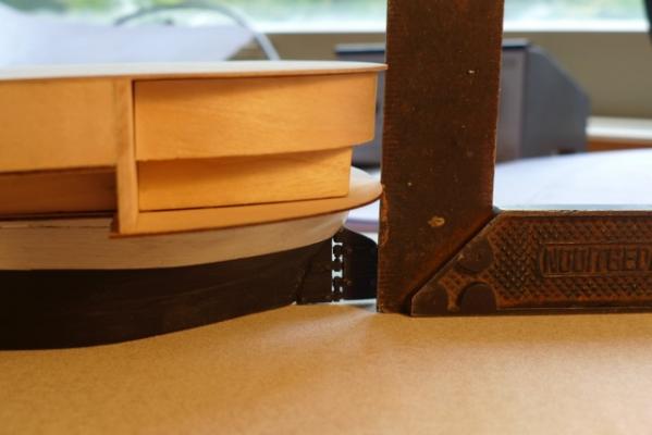
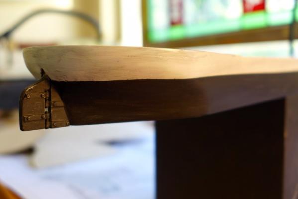
Thanks Jim - I just hope I can keep it up. Once you start these logs the pressure is on to keep going. I hope you are enjoying some deja vu. 6. Cabins A,B & C. This is where it starts to get a bit interesting – having to build the stern structures that match the inclination of the first deck but where the walls have to be perpendicular to the water line. Instead I decided to build cabin E first, thinking I could build the stern structure up against cabin E. 8. Cabin E. The cabins are built effectively top to bottom, by building the walls of each cabin onto the underside of the deck piece above the cabin. The first point here is to check the width of piece 87 (i.e. the roof of cabin E) and confirm that it is the same as the width of the underlying deck piece (piece 14). Note. It is not clear from the drawings or stated in the manual but the objective is that the port and starboard faces of Cabin E, plus the face of the paddlewheel housings, have to line up with the edge of the first deck after the faces are planked. This is illustrated in the next photo. As you will see I have progressed with the build ahead of this log so I can show you how it is meant to look at the spot where the faces and the edge of the deck line up. So when building Cabin E check that the width matches up with the width of the first deck. Alternatively the edge of the deck has to be trimmed back to the face of the cabin. (That is a piece of balsa placed under the first deck to keep the deck line straight for the purpose of the photo) The dimensions of the walls of the cabins are scheduled on the plans and are cut from stock lengths of 3mm x 35mm strips (looking like good quality limewood). (In the case of the curved cabins B & C I found it better to cut the walls using the roof piece as the template.) Cabin E was completed without too much difficulty but be sure to work to centrelines and ensure all walls are square and plumb.

- 94 replies
-
- 1
-
-
- robert e lee
- amati
- (and 1 more)
-
5. Installing the first deck. The next step is to install the first deck that consists of 4 pieces of 1mm laser cut sheet. It was at this stage that I learnt an important point about this model. Firstly, being laser cut components you would expect them to be very accurate in shape and size. This is not so and it got me into some trouble that will be mentioned as we go. Secondly, the tolerances in building the model are quite tight in some cases. A mm out here and there can add up to a critical misalignment that can cause headaches later, and again will be mentioned as we go. Alignment of the deck components 13, 14, 15 & 16 is important and this is achieved by marking centre line on the hull and on each deck component. I determined the correct location for item 14 by laying out the deck pieces on the hull and glued and nailed it into position. Pieces 13 and15 were then fixed into position butting up to piece 14, then finally the stern deck piece 16. The joint between 15 & 16 coincides with the joint at the built up section previously fixed to the hull.
- 94 replies
-
- 1
-
-
- robert e lee
- amati
- (and 1 more)
-
Thankyou Bettina. That was quick - hardly enough time for the ink to dry on my first post. 2. Painting the hull. I sealed the hull before painting and it proved to be a good move as the material used for the hull was rough to start with and ‘fluffed up’ further when painted. Sanding after sealing gave a very dense and smooth surface. The picture on the box illustrates a pristine model mostly painted in white. I have decided on a weathered model, a decision I might live to regret as I am no expert in weathering techniques. Anyway I have started the weathering process on the hull as you can see but I am not happy with it and I will do some more work on it at a later stage. To be honest I didn’t spend too much time on the workmanship in painting the hull as I reckon that when the model is finished any observer inspecting the model would have to get on his/her hands and knees to see it because of the overhanging deck. Or am I fooling myself?
- 94 replies
-
- 2
-
-
- robert e lee
- amati
- (and 1 more)
-
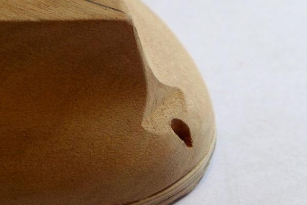
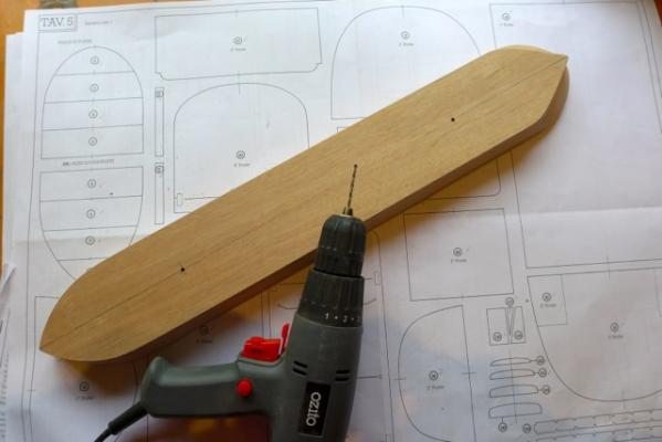
4 &3. Rudder and Keel. The instructions suggest proceeding with painting the hull and then to construct and install the rudder and keel. But it seemed to me simpler to build the rudder and keel first, prepare the hull for placing the keel, then install onto the hull before painting. Before I went any further I drilled two holes on the underside of the hull for mounting the model later on. I have no idea how this will be done but it is easier to drill holes at this time than when the model is complete.


- 94 replies
-
- 4
-
-
- robert e lee
- amati
- (and 1 more)
-
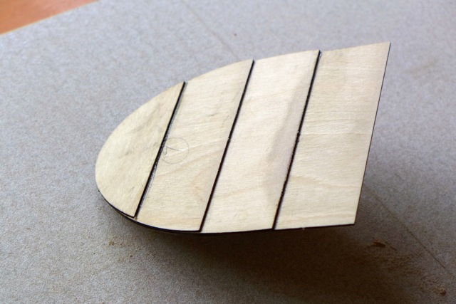
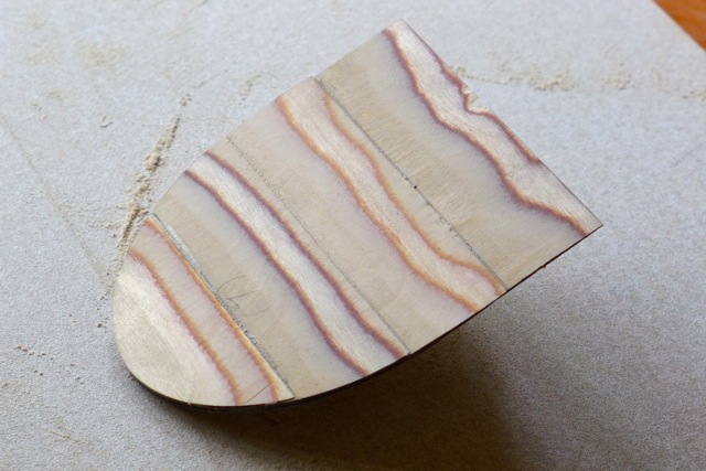
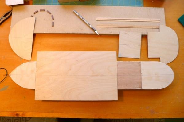
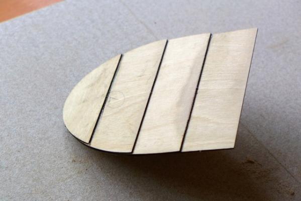
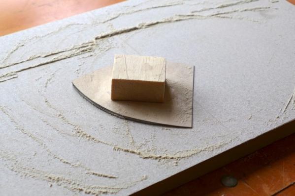
1 & 1a. Building the hull. The kit comes with a well-made solid hull, in some compressed woodchip material, unknown to me, that saves a lot of time in getting started on the model. The first step is to prepare the components for the inclined sections at the fore and aft of the hull deck. Four pieces of laser cut ply are glued together and the challenge is to sand the part to remove the steps to a smooth taper. I spot-glued a balsa block to the back of the glued parts that acted as a handle, and used a sanding bed to remove the steps. The sanding bed is a piece of 19mm MDF covered with a sheet of sanding paper that I have used in building plane models. A disc sander or belt sander would be ideal if you happen to have one although the sanding bed proved useful in later stages of the project. The sanded components were glued and nailed to the hull. Some sanding was required at the edges, after fixing, to mate them with the hull.
- 94 replies
-
- 1
-
-
- robert e lee
- amati
- (and 1 more)
-
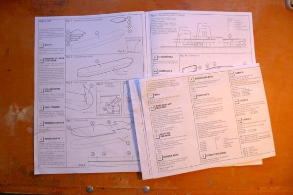
The drawings and instructions are well drafted and detailed but are all in Italian. The step-by-step instructions are in a separate manual with illustrations for each step where appropriate. Fortunately for those of us with no knowledge of Italian another instruction manual in A4 is provided in English that matches the step-by-step instructions in Italian but without the illustrations. So you need both manuals to be open side by side as you progressively work through the steps. The manuals and drawings are clear but how adequate they are remains to be seen. However builders should no be discouraged from getting the model just because of the Italian bit. Note that the numbers in the following log refer to the building steps in the manual.
- 94 replies
-
- 2
-
-
- robert e lee
- amati
- (and 1 more)
-
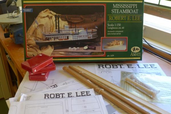
I purchased the model via email from a UK supplier well known to MSW modellers and the kit arrived in Australia in a record time of 5 days! The cost of the kit plus delivery was well below local prices as I am sure many others have experienced. The kit is very impressive, well packed and on first inspection good quality. The kit does not come with a detailed list of items that can be used to check the kit contents, however I quickly realised that there was a missing a large 1mm sheet of laser cut pieces. The supply company and/or Amati willingly replaced the item but for some reason it took a ridiculous 6 weeks to be delivered compared to 5 days for the original kit. I exchanged several emails with the supplier in frustration while waiting for the delivery and was assured that it was on the way. I have concluded the method of delivery, hence the time taken, depends on who is paying for it. I have never experienced missing components in the many kits I have purchased over the years. However the moral of this story is it does pay to CHECK YOUR KIT CONTENTS as best you can on delivery, as it may be difficult to claim missing components weeks or months after the delivery date.
- 94 replies
-
- 1
-
-
- robert e lee
- amati
- (and 1 more)
-
After some consideration and discussion with various MSW builders who have built river paddleboat models, I decided my next model would be the Robert E Lee by Amati. Detailed rigging is getting a bit fiddly for me in my later years and the RE Lee offers an interesting alternative. There is presently no building log on the MSW site of the RE Lee. There was one by Jim (aka Script) before the meltdown late 2012 and Jim has helpfully re-posted some progress shots. Since there is no complete log of the RE Lee on MSW I have decided to start one, mainly in the hope that it will assist any newcomer to the hobby who wants to try this model. So here goes!
- 94 replies
-
- 3
-
-
- robert e lee
- amati
- (and 1 more)
-
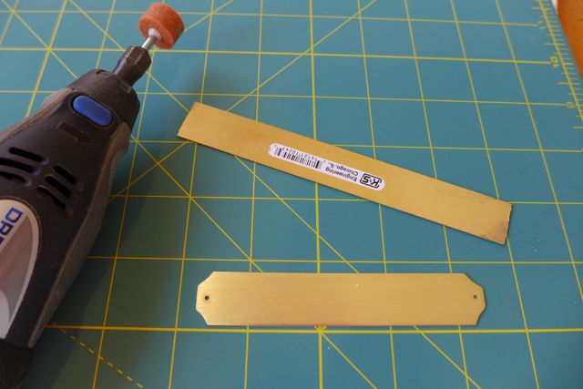
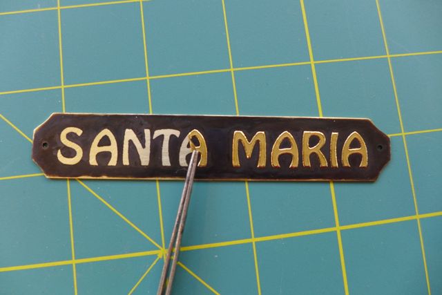
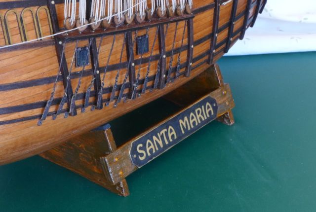
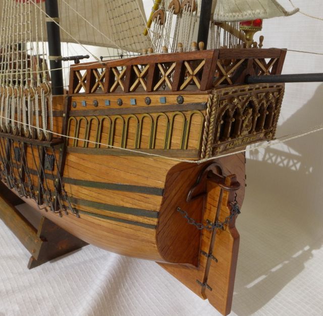
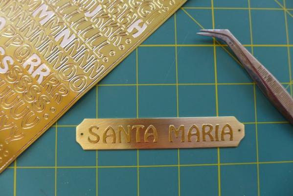
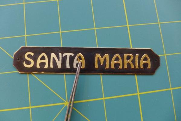
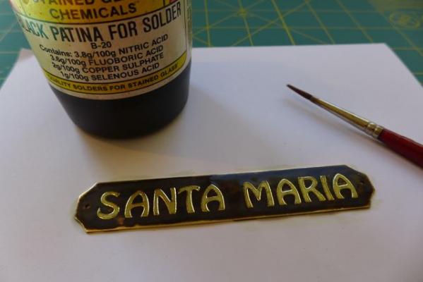
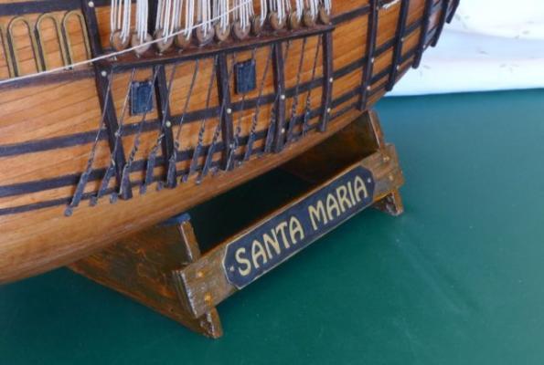
A recently completed model of the Santa Maria didn't include a nameplate so I needed to make one. After considering various options I decided the following method was the simplest and quickest. I purchased a strip of brass plate from which I cut, shaped, and drilled the nameplate. I then cleaned the surface with steel wool. I obtained a sheet of 'stick on' letters from a craft type shop, normally used for making cards etc. Each letter was transferred from the sheet to the brass plate. I had previously made a mock-up of the nameplate on a piece of paper to be sure the letters fitted ok. I painted onto the brass plate a generous coating of 'Black Patina for Solder' that I had left over from the days when I did some leadlighting. Interestingly the brass didn't go black (I have used it to blacken other boat fittings) but a dark brown instead, probably to do with the properties of the brass strip. However the result was quite satisfactory for my purposes. After allowing the black patina to dry I removed the letters. Fortunately the adehsive on the letters was very good and there was no leeching of the black patina under them and the letters were well defined. I did have second thoughts about removing the letters as the nameplate looked ok with them on but decided that long term they could come off as the adhesive deteriorated or for some other reason. A view of the nameplate attached to the model base. The exposed brass letters will mature in time as the brass slowly tarnishes. The cost of the nameplate was no more than $A5 and I still have brass strip and letters to make two more.


-
Thankyou Mark, Grant and Harry for your feedback. A compliment or two goes a long way when working in isolation, as we do, in this hobby our ours. I am getting a bit long in the tooth to tackle another major project but I will have to find something to fill in those spare moments. I am looking at a paddle steamboat (no rigging!) just for a change but in no hurry yet. I have made a nameplate for the Santa Maria which has come up pretty well. I think I will post a log on how I made it under building techniques.
- 39 replies
-
- 2
-
-
- santa maria
- mantua
- (and 1 more)
-
Having finished the model a review of the kit is appropriate. I chose the Mantua kit as it appeared to be the best design of the alternatives available. Still believe this and am quite happy with the result. However for a novice modeller I think the Mantua Santa Maria would be a challenge. Not because of the design itself but because of the lack of good instructions and conflicting details in the manual and the drawings. Even the picture of the model on the box did not match the instructions or materials provided particularly in regard to the rigging. The manual consisted of pictures only (no written instructions whatsoever) and the quality of the modeling illustrated in the manual was average. The drawings were detailed and impressive but again contained conflicting details. The rigging in particular would be difficult for a novice in the absence of written explanations and the rigging and sail materials provided. For an experienced modeller the Mantua kit would be disappointing. For example the preprinted decks and gunwales (I decided to buy deck planking), the use of balsa for the first planking (I purchased limewood in lieu), the quality of the timber provided (but this didn’t concern me as I coloured the timber anyway), the rigging (in scale, not quality), and the sails (which I made in alternative material). Despite the above I have finished up with a small but interesting model with I reckon lots of character. I was able to build it in a reasonable time period of seven calendar months less a couple while on hols. It does not have the perfection that I see in other models on MSW but it suits the purpose and will go well in my son’s study or living room I am sure.
- 39 replies
-
- 1
-
-
- santa maria
- mantua
- (and 1 more)
-
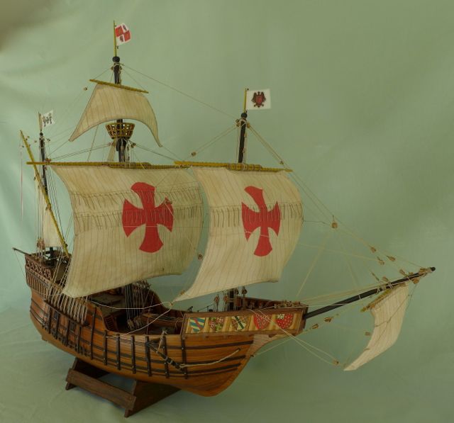
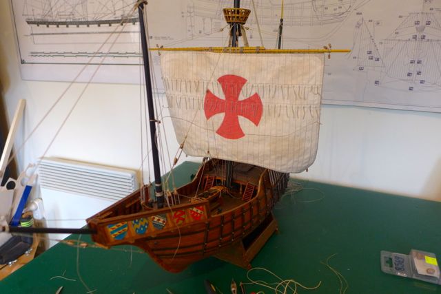
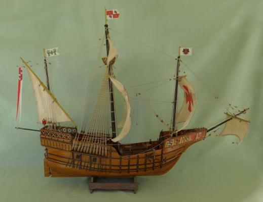
Finally finished and as usual took longer than expected to fix the last bits and pieces. I used the flags as supplied as I was unable to find any alternative. The result is disappointing as they don’t fit in with the general style of the model. A few photos of the finished product follow. I plan to put a name plate on the stand (not supplied with the kit) and make a display case one day but that can wait.


- 39 replies
-
- 5
-
-
- santa maria
- mantua
- (and 1 more)
-
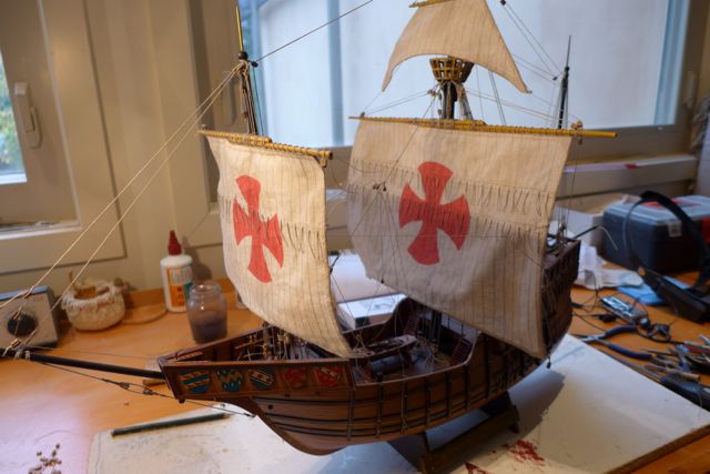
Getting there. Took me a while to get going after returning from holiday but well into it now. Three sails rigged. Two to go. Two days per sail, one day for rope coils, another deck furniture, and a last for final touches. Total 7 days. I wish, but this is how the mind works when you get close to finishing. Ropes hanging everywhere as loath to secure any rope until all, or most, are in position and don’t snag each other etc.

- 39 replies
-
- 2
-
-
- santa maria
- mantua
- (and 1 more)
-
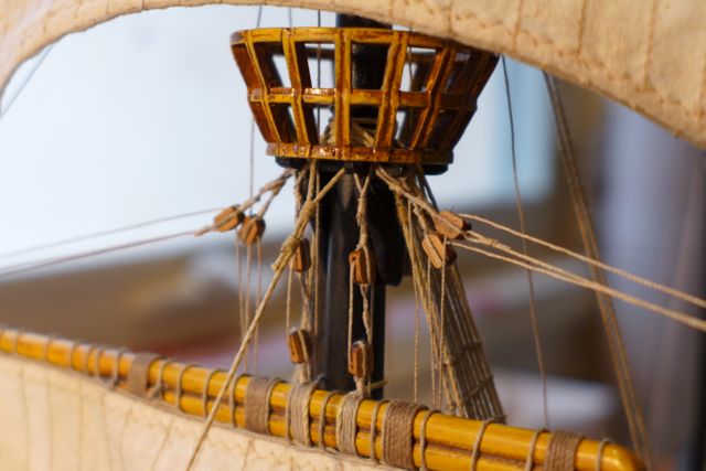
After the diversion with the coats of arms I pressed on with the rigging and sails. I noted that there are 104 blocks on the model which sounds a lot for a smallish model but when you get involved with sails there are blocks everywhere and they are certainly time consuming. I have now hoisted the mainsail with ropes dangling all over the place. I have realised it is difficult to tie off any ropes before all the sails are assembled as access is very limited. I think I can billow the sails Captain Steve without too much difficulty and I reckon they have to be billowed as straight hanging sails would not look right on this model. Unfortunately I am about to go on a holiday o/s so this will be the last post for a couple of months. Unlike many others I won't spend too much time thinking about what I would like to build next time but I assure you, Micahel D, it certainly won't be the Wasa!

- 39 replies
-
- 1
-
-
- santa maria
- mantua
- (and 1 more)
-
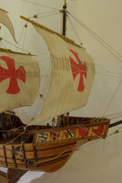
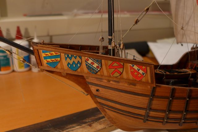
I decided to take a break from the sail making and rigging to add a feature to the ship that I had seen on another model of the Santa Maria. A row of coats of arms on the sides of the bow of the ship would add some interest I thought. It so happens that I had a book on English and Scottish heraldry. (I knew it would be useful one day!) I colour copied some of the samples of coats of arms, reducing them in size to suit the scale of the model. I selected examples that looked the least like English or Scottish coats of arms for obvious reasons. I cut them out, glued them onto a 0.5mm sheet of ply before gluing them onto the model, five aside. I then coated them with shellac which gave them a mellow tone that matched the colouring of the model. I must say I am quite chuffed with the result. Pity they are not Portuguese/Spanish coats of arms but if my son spots it I will bare my backside in Burke St as we say in Melbourne.

- 39 replies
-
- 4
-
-
- santa maria
- mantua
- (and 1 more)
-
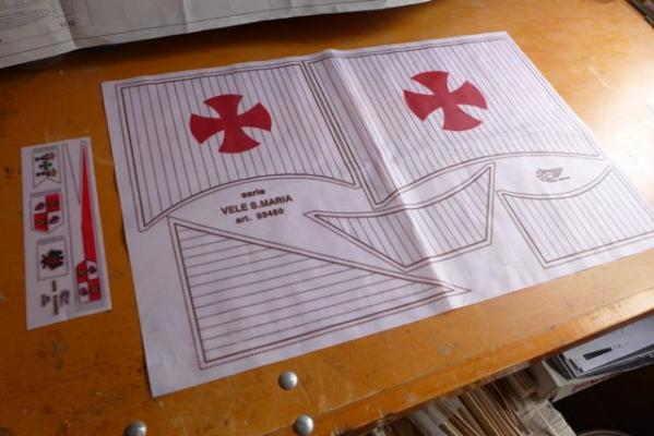
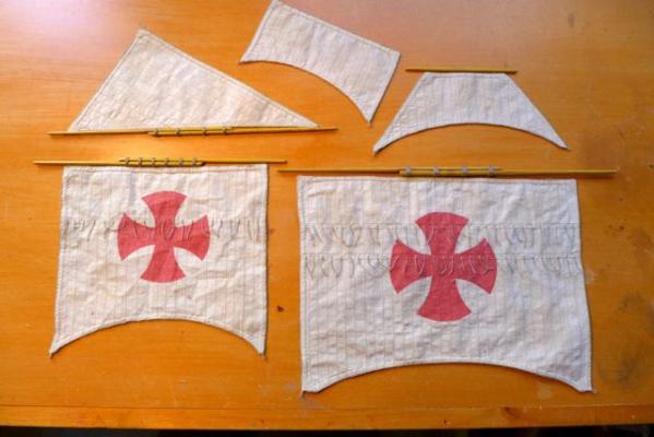
I managed to borrow a sewing machine from a good friend to tackle the sails. If I had asked nicely she might have been prepared to make them for me but I like to be able to say of a finished model I made it all. Making sails is fiddly but fairly straightforward and I don’t have any tricks etc. but just for the record here is my recipe. I chose calico for this project being off white to start with to suit the model. I washed and dried the material (to avoid shrinking problems later), tinted them by soaking in a brew of tea (it is pot luck what colour you finish up), dried it naturally, ironed out the creases, marked out the sails with an air eraseable pen (thanks to Hopeful for this helpful suggestion), cut out the sails, pressed the edges ready for sewing(very fiddly), sewed the edges using the sewing m/c (in cross-stitch) and then the vertical sheet joints. Then I wet the sails, wrung them out by rolling up in a towel, laid them out to dry but while still damp sprinkled them with a few drops of coffee (black) to add to the aged look, and allowed to dry. I didn’t iron the sails when dry as the wrinkles again add to the aged look. Then I stitched on the rope edging (very tedious but was able to watch tv at the same time). I painted the red crosses by cutting out a stencil from paper, stuck the stencil on the sail using spray adhesive, and painted with off the shelf spray can of gloss enamel. The sails were painted front and back. Finally I sewed on the reefing ropes. I will straighten them out later when the sails are installed. Finally I reinforced the corners by gluing on patches from the sail offcuts which also helped to camouflaged some bodgy sewing, as the corners are difficult to sew neatly. The photo does not show the colours that well, hopefully they will look ok when installed on the model. Getting close to a finished model and I have the feeling of it being downwind from now on.
- 39 replies
-
- 2
-
-
- santa maria
- mantua
- (and 1 more)
-
The kit comes with a sail and flag set preprinted on silk. Since the sails are going to make a big statement in this model I don’t think the silk is a good solution so I plan to make the sails in a more suitable material that I can colour to suit the style of the model. Now looking for a friend who has a sewing machine. Not too sure what I can do with the flags.