drobinson02199
-
Posts
1,079 -
Joined
-
Last visited
3 Followers


About drobinson02199

Recent Profile Visitors
4,494 profile views


-
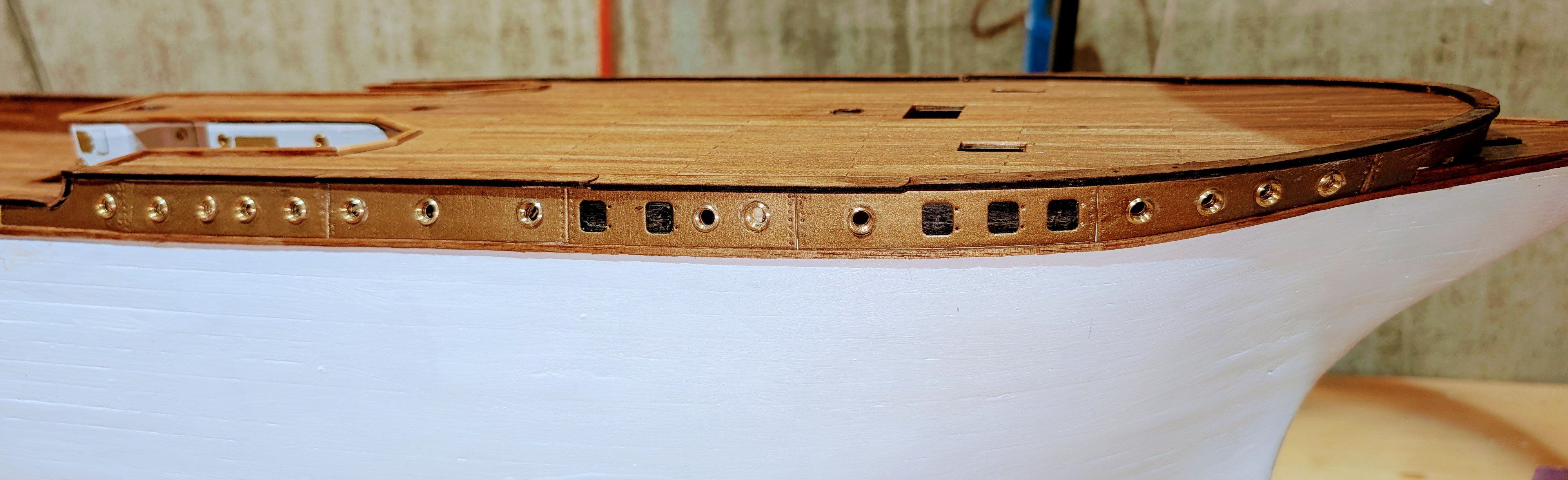
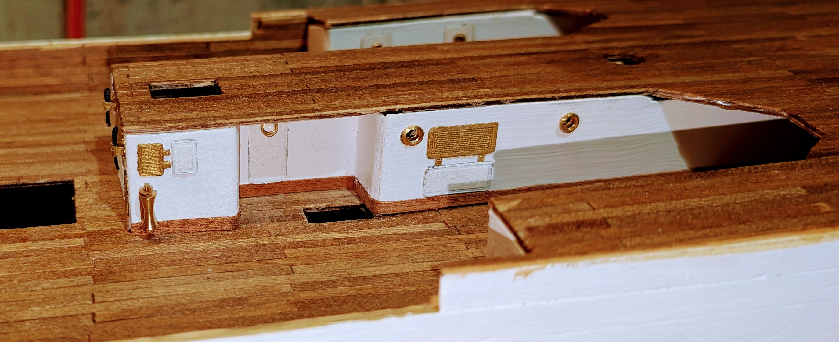
 Side moldings now installed. All of the holes will have brass airports installed (same as on the bronze strip above), which will look really nice as long as I dont mess it up drilling out the holes. I've now finished book 2 of 8 instruction books, and I'm just about at 4 months -- so this will be a 1 1/2 year build if that timing holds. Regards, David
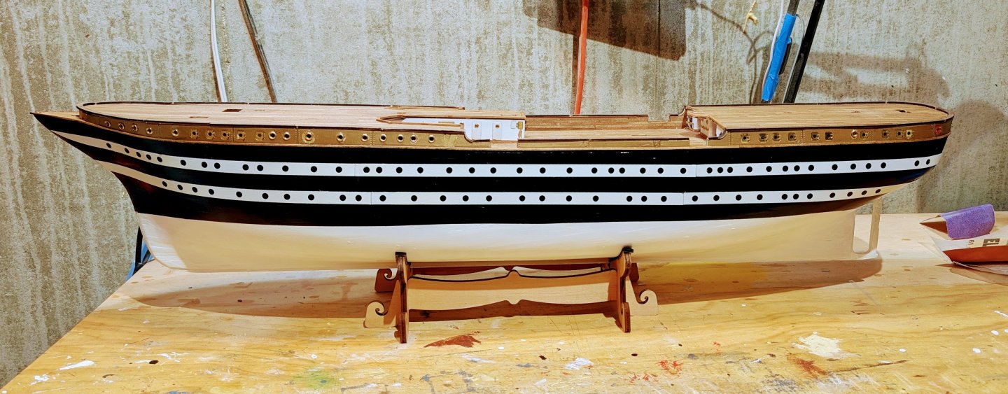
-
 BlackDog reacted to a post in a topic:
Amerigo Vespucci by drobinson02199 - Mantua - Scale 1:84
BlackDog reacted to a post in a topic:
Amerigo Vespucci by drobinson02199 - Mantua - Scale 1:84
-
palmerit reacted to a post in a topic:
Amerigo Vespucci by drobinson02199 - Mantua - Scale 1:84
-
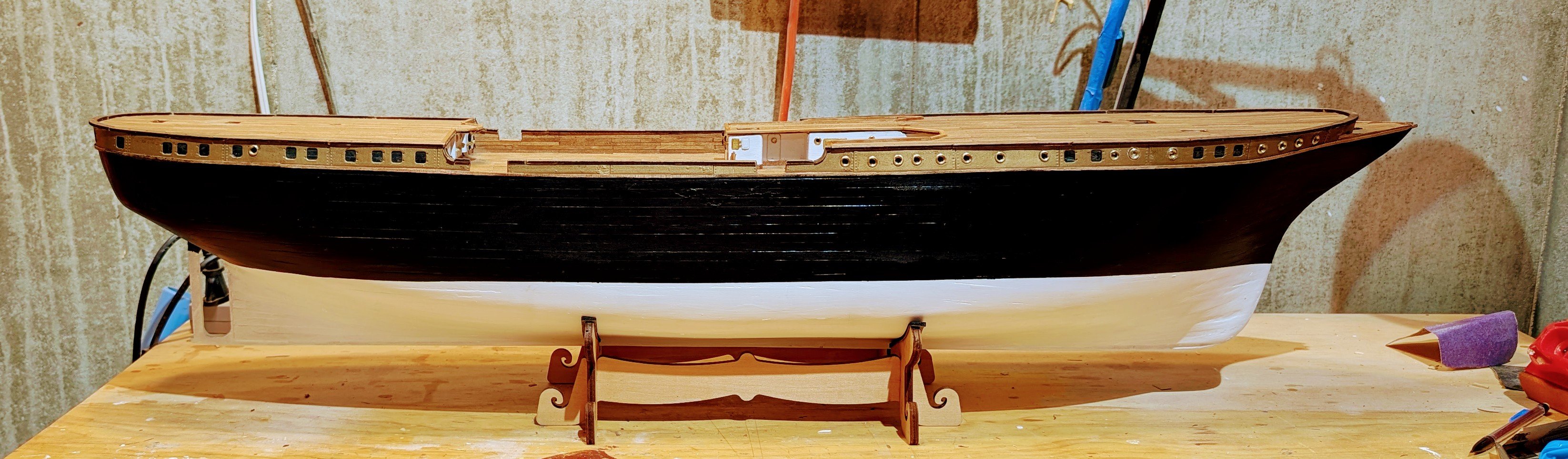
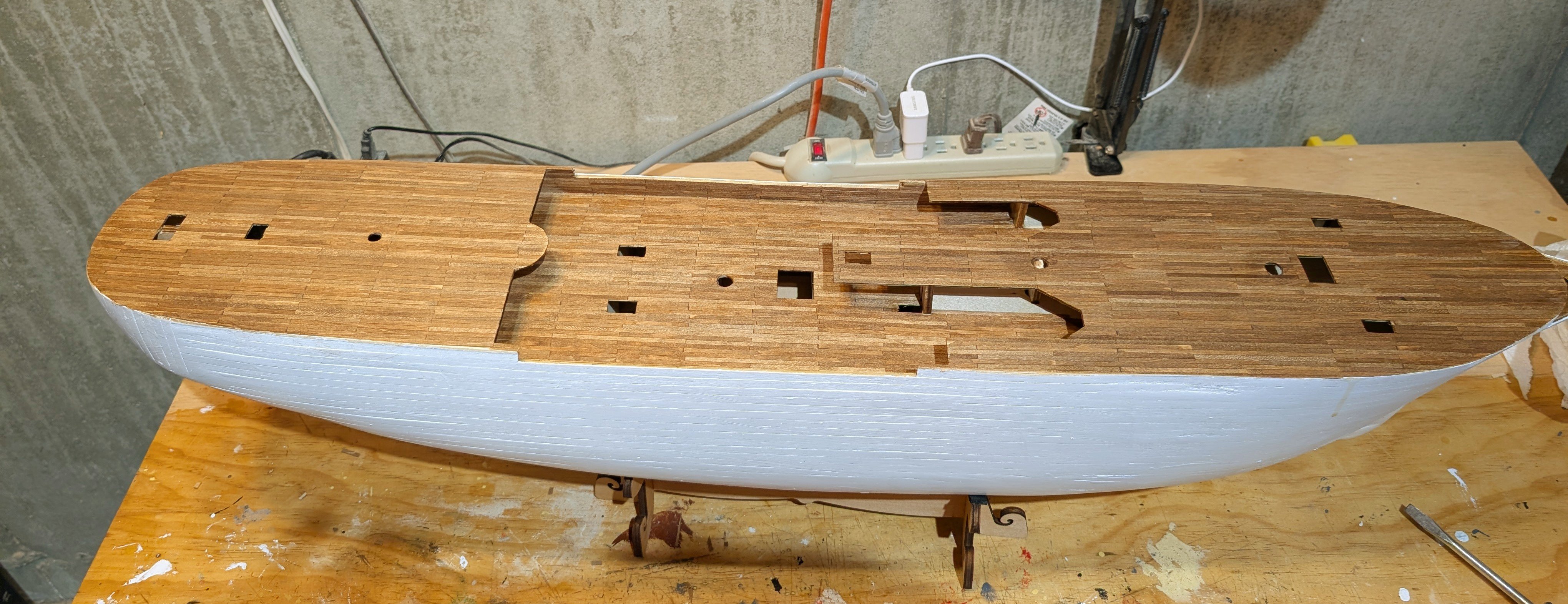
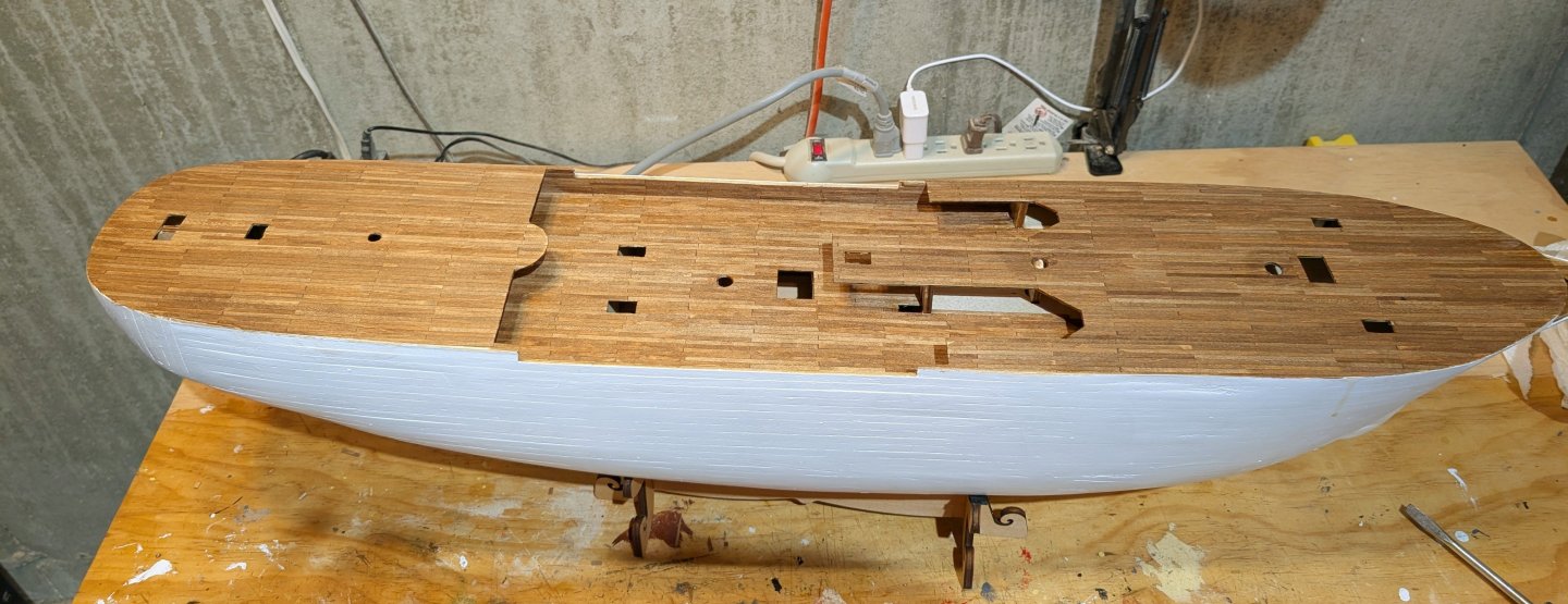
I've now painted the top half black down to the waterline. Next step will be ro varnish it to protect it before applying the white side moldings. Interestingly, the manual has the hull black down to the keel, but all the pictures show the white bottom as I've done it. That will look much sharper, I think, so that's what I went with. Regards, David
-
Both layers are lime -- the first is 1.5mm thick and the second 1.0 mm thick. The deck planking is walnut, stained dark with the stain provided in the kit. The manual calls for the hull to be sealed with Modelspan tissue and nitro dope, but I didn't do that. Regards, David
-
BlackDog reacted to a post in a topic:
Amerigo Vespucci by drobinson02199 - Mantua - Scale 1:84
-
Kelp reacted to a post in a topic:
Amerigo Vespucci by drobinson02199 - Mantua - Scale 1:84
-
Painted and installed the bronze colored side moldings, and installed brass airports. Getting those right is HARD in terms of drilling out the port to the right diameter without damaging the side moldings. There are some rough ones on the other side. Fortunately, these moldings are covered with a lot of rigging, so my mistakes won't show as much. Then installed capping on top of the deck edge, and wood molding strips under the bronze molding. Regards, David


-
More interior walls. Regards, David


-
I've been working on the sidewalls, and finally got the one under the stern deck finished and mounted. Really nice decoration on these. And yeah, I didn't get the railing in the center quite level. Tip: This wall section bows backward, so to straighten it out I glued small stops under the deck on the extreme left and right. They catch the ends and then you can push the assembly back until it's straight. Regards, David


-
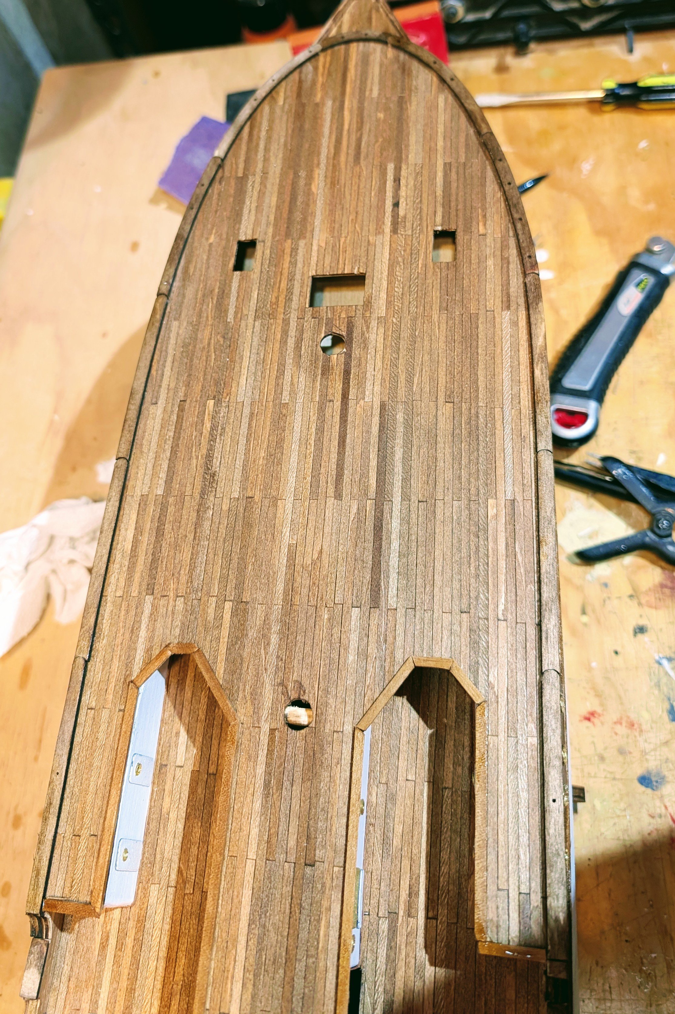
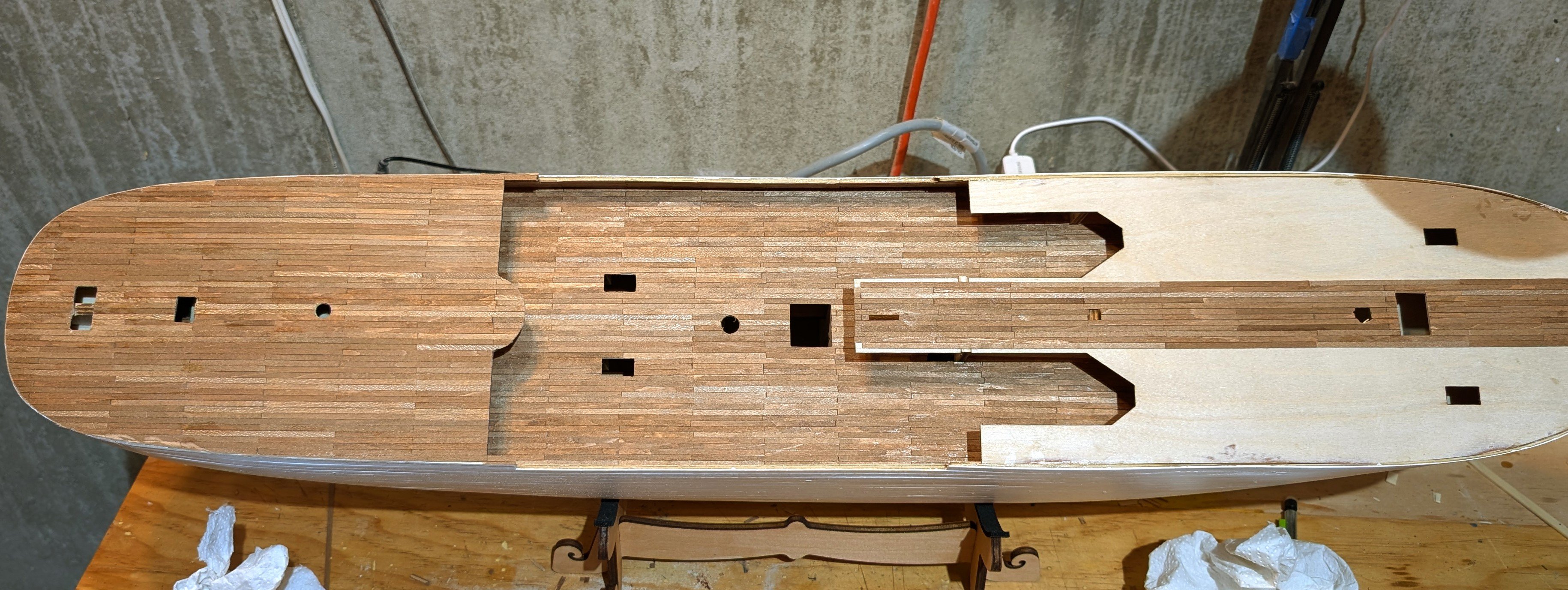
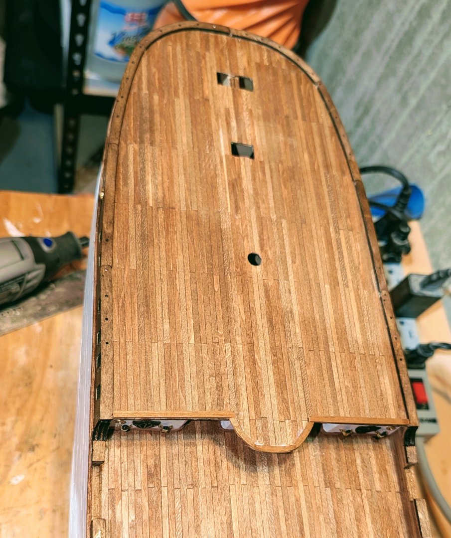
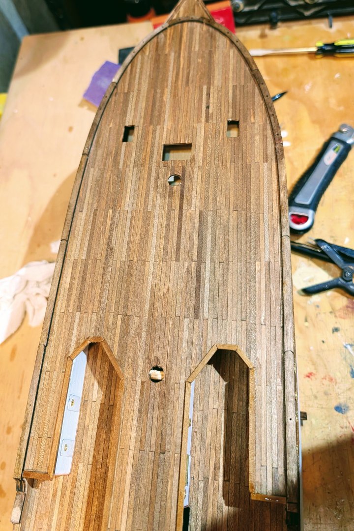
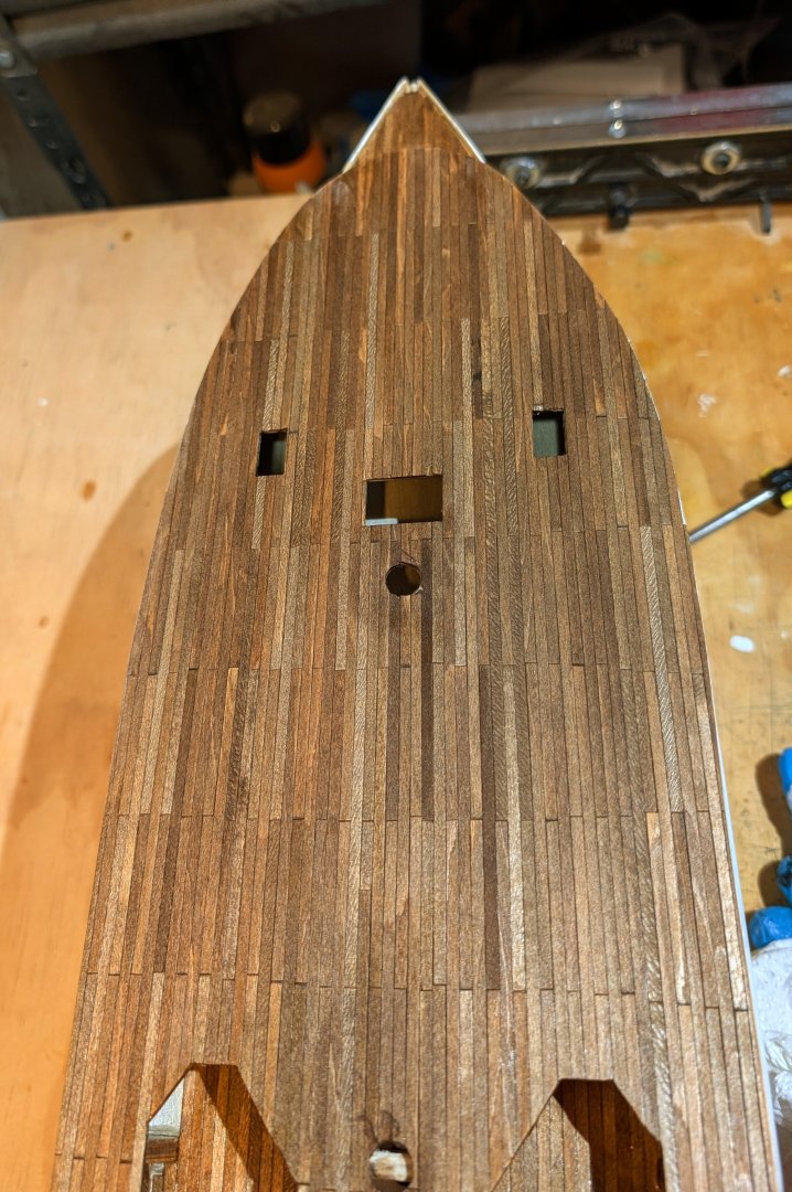
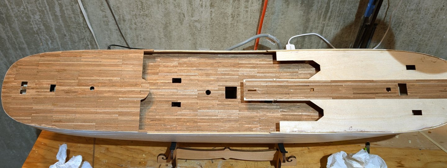
Finally finished the deck planking. These pictures show it with two coats of varnish. The stained decking strips came out with a nice look. Regards, David
-
Working my way through the deck planking. As per the instructions, I built a jig to install plank sections. Can't wait to sand and varnish this. Regards, David
-
king derelict reacted to a post in a topic:
Amerigo Vespucci by drobinson02199 - Mantua - Scale 1:84
-
king derelict reacted to a post in a topic:
Amerigo Vespucci by drobinson02199 - Mantua - Scale 1:84
-
king derelict reacted to a post in a topic:
Amerigo Vespucci by drobinson02199 - Mantua - Scale 1:84
-
king derelict reacted to a post in a topic:
Amerigo Vespucci by drobinson02199 - Mantua - Scale 1:84
-
king derelict reacted to a post in a topic:
Amerigo Vespucci by drobinson02199 - Mantua - Scale 1:84
-
DARIVS ARCHITECTVS reacted to a post in a topic:
Revenge by drobinson02199 - FINISHED - Amati
-
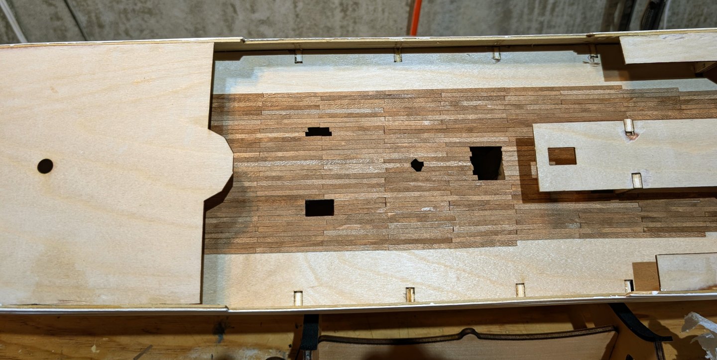
Here's deck planking in progress. The strips have to be stained (as noted above for the small bow section), and I think the deck will look pretty good when varnished. I'm going to have to test to see what kind of sanding will work, as I'm concernd that normal sanding will take off the stained layer. But without sanding, a slightly weathered appearance will look good. Regards, David
-
drobinson02199 reacted to a post in a topic:
RMS Titanic 1912 by klaasvg - Amati - Scale 1:250
-
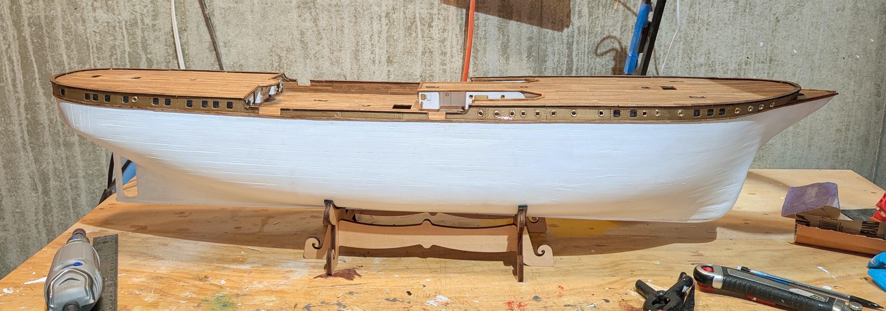
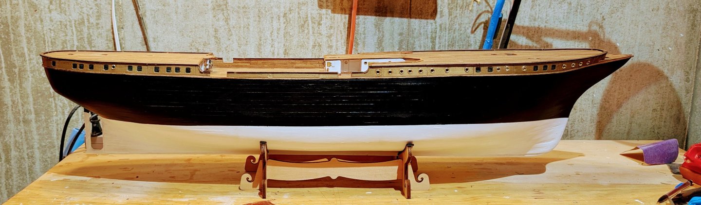
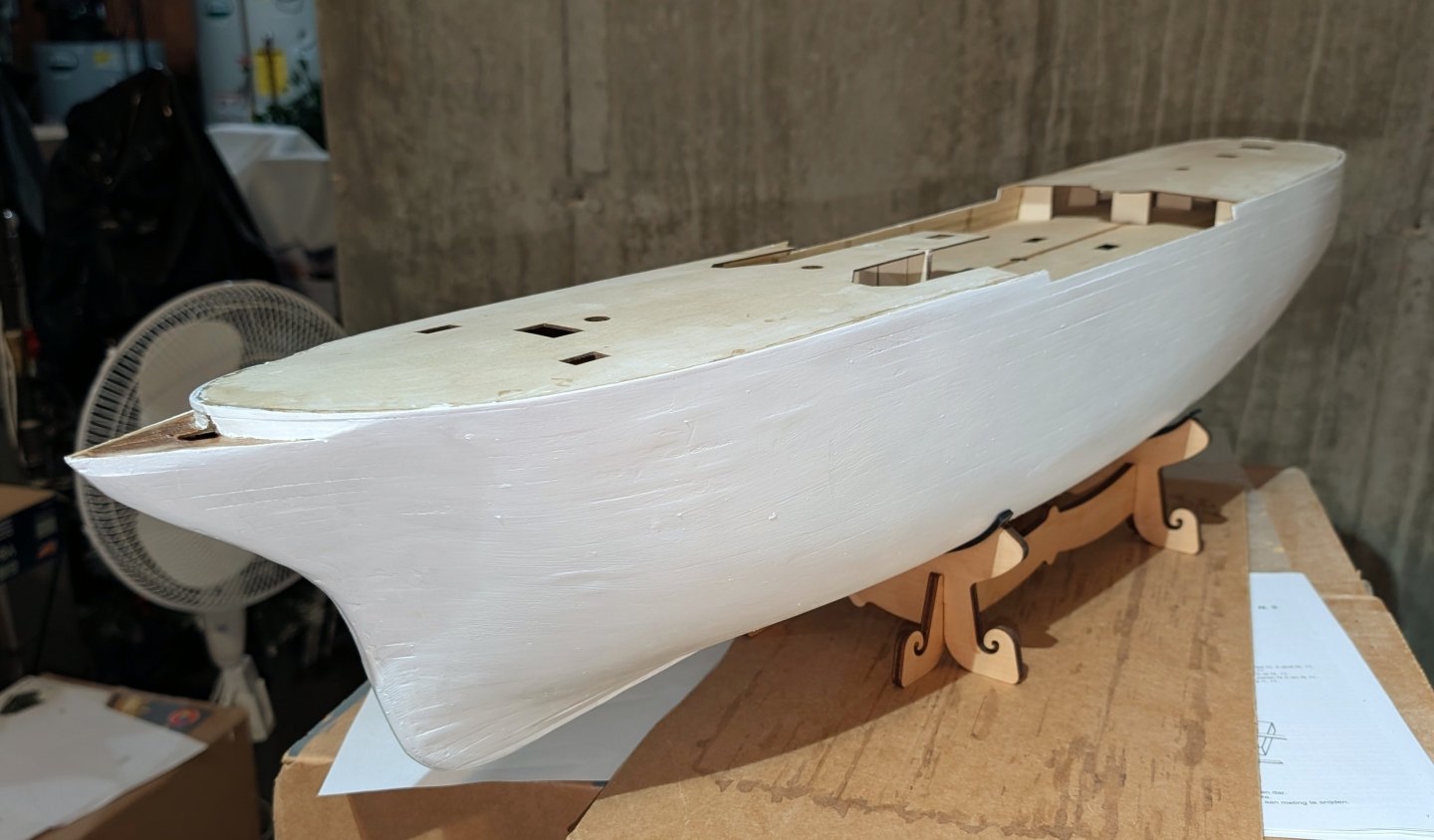
Here's the finished hull. I did about 4 coats of varnish and two coats of paint. Regards, David
-
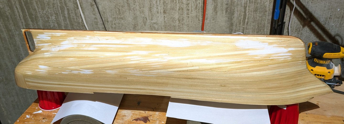
Here's the second planking, sanded and filled, with one coat of varnish (still wet). Now to see how smooth I can get it with varnish coats alone. If not successful, then I'll give the Modelspan paper a try. Regards, David
-
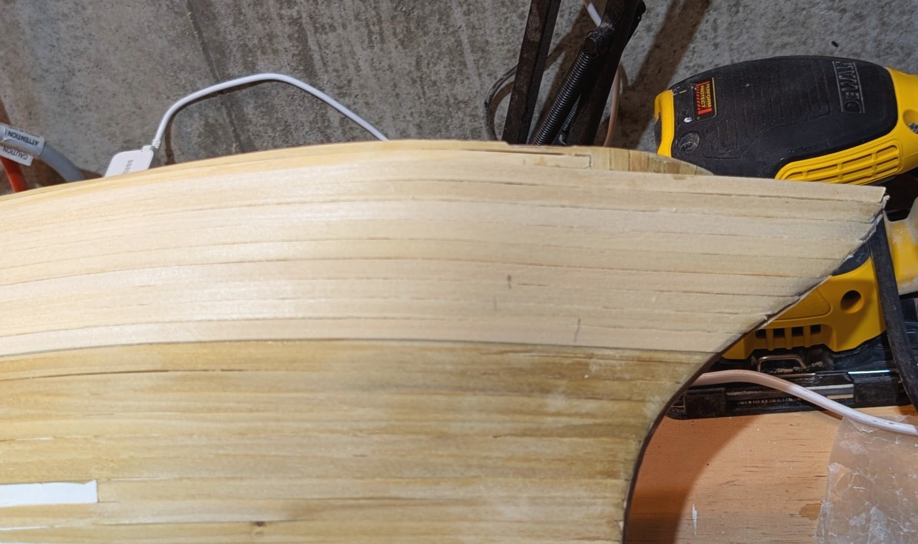
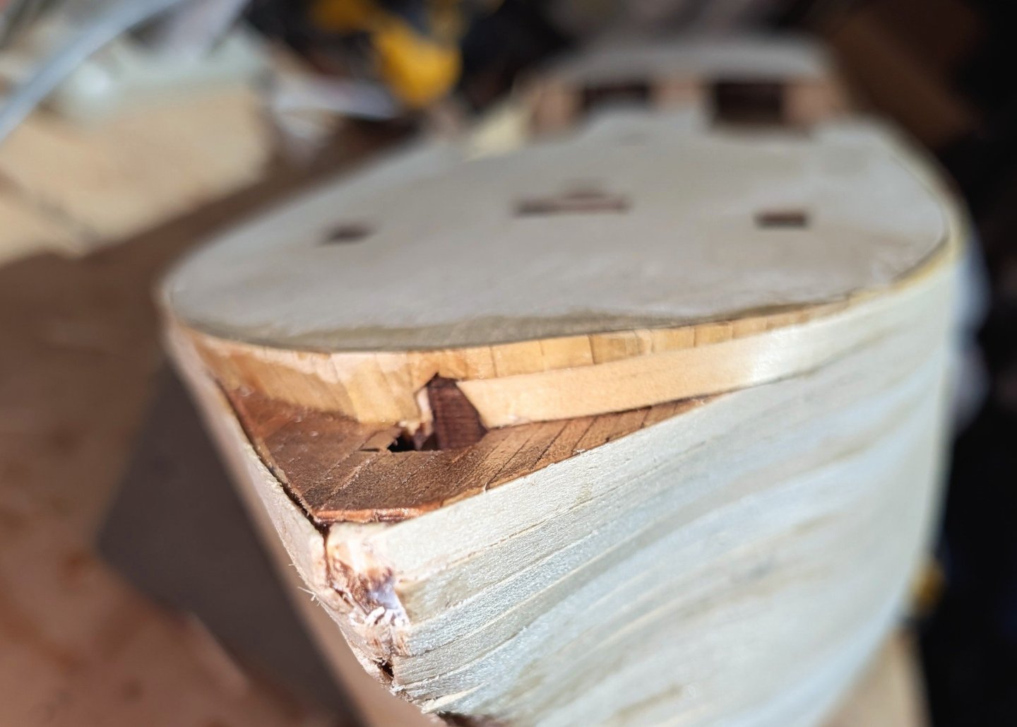
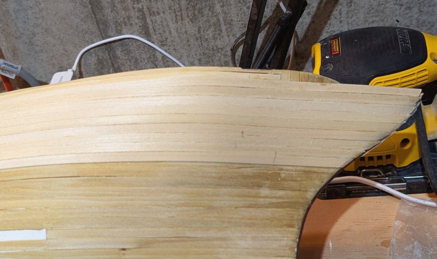
I'm able to use horizontal planks at the bow because the second planks are very flexible (with steaming), and only two rows will be needed. At the stern, I don't think horizontal will work because the curves would require lots of stealers. The stern is easy to sand smooth -- the bow is difficult to get to, which is another argument for horizontal planks. On the right, it looks in the photo like the plank has buckled, but it's actually a smooth curve. Regards, David
-
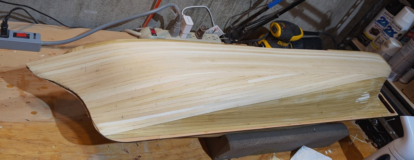
Continuing to motor on through the second planking. Tapering at both ends started as I move down the hull. Regards, David
-
I've started the second planking, and I'm pleased with the way it's laying. Very smooth, and the planks are very flexible. The kit supplies Modelspan tissue for a final step on the hull, and I've been mulling over whether I should try it. Having researched it, I have a pretty good idea of what's involved in using it, and I'm not totally comfortable. If the second planking remains as smooth as I go around the curve of the hull and taper, I'll probably stay with multiple coats of varnish and sanding. Regards, David
-
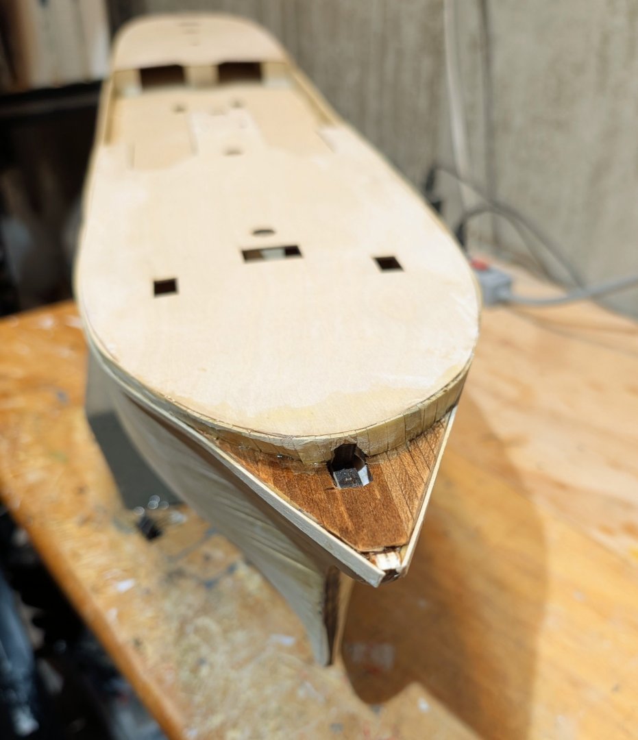
I varnished the little deck section at the bow to protect it. The stained wood comes up nicely under varnish, so the main decks are going to look really nice. The two shades aren't as pronounced to the naked eye. The alphaic glue seemed to work fine as a first planking sealer/smoother, but I think I'll use varnish on the second planking -- unless I decide to go forward with the Modelspan paper and nictric dope (called for in the instructions), which at the moment I'm disinclined to do. Regards, David