Check out our new MSW Sponsor Innocraftsman
×

Sharpie
-
Posts
69 -
Joined
-
Last visited
Content Type
Profiles
Forums
Gallery
Events
Everything posted by Sharpie
-
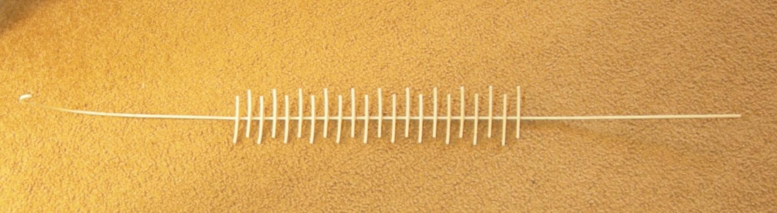
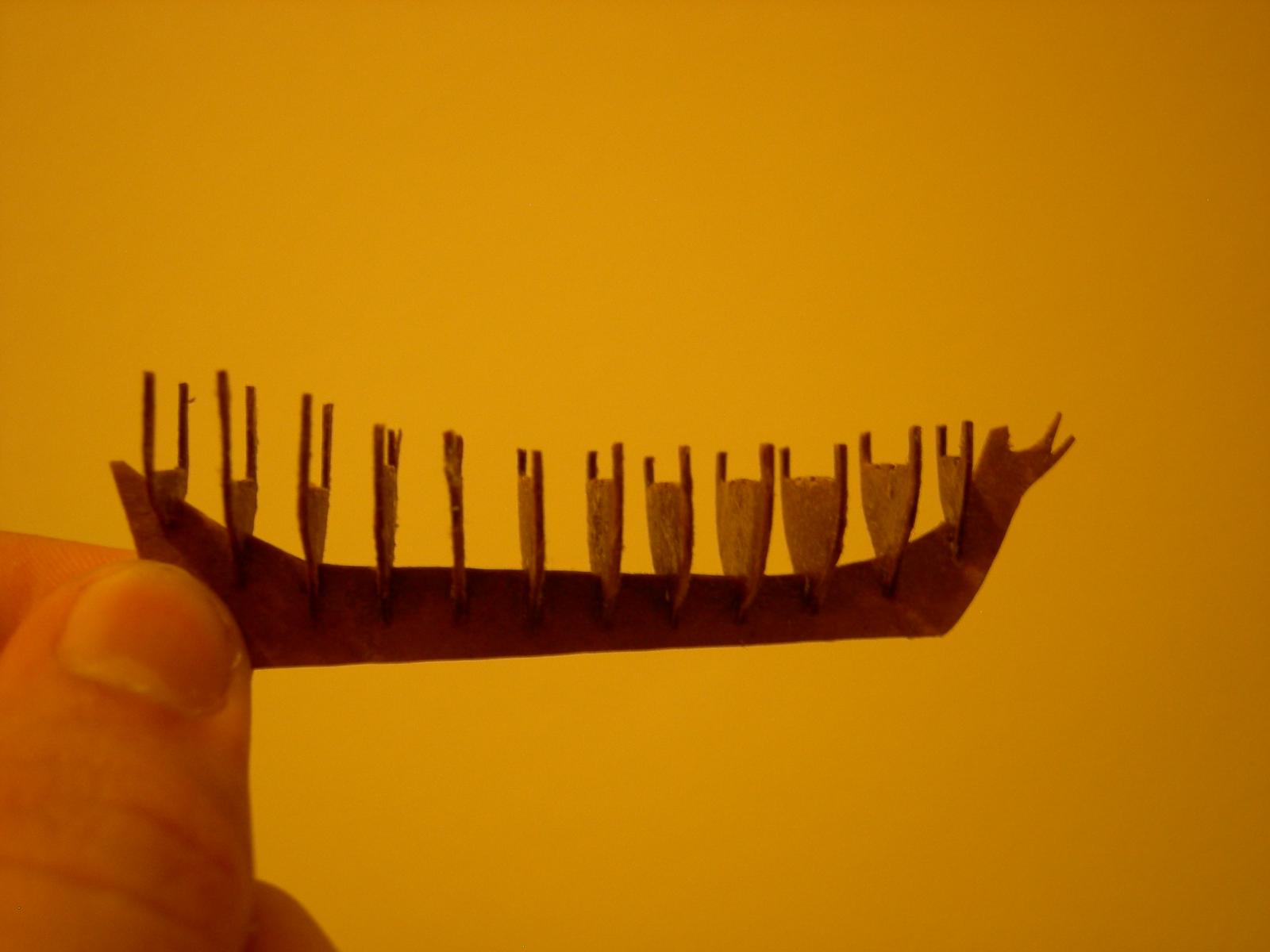
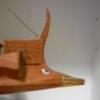 OK, here's where I'm at as of this afternoon: A total of 31 floors made and dry-fitted onto the keel, with about 15 more to go. The last five or so on the stern will be single-piece frames, since the cross-sections of the tail are so small. Once I stain all the floors, I might have to find a photo backdrop that's not brown…
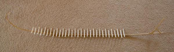
-
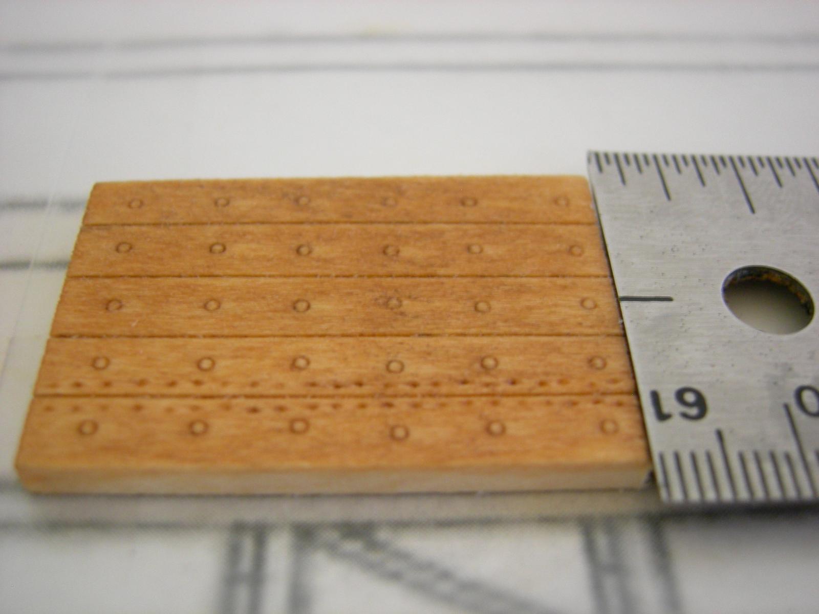
Sorry for the lapse over the past week-- life had the temerity to get in the way of my model ship building. For the tree nailing detail, I've decided that I really like the looks of the ring impressed in the wood, despite the potential inaccuracy of the treenails not being darker. The larger treenails, which would hold the ribs to the inside of the hull, will be represented as shown on my test piece, with the 0.7mm ring on the planking and on the insides of the ribs. The smaller treenails, which would hold the mortise and tenon joints together, will be represented by either 0.3mm or 0.4mm rings, depending on what size mechanical pencils I can get my hands on. These will be set 1/4" apart (1ft/30cm at full size). This is much farther than is shown on the Olympias, but it doesn't seem too unreasonable given the size of the ship and the dimensions of the planks. I would like to show these on both the outsides and the insides of the planks, as if they really went all the way through, but I may change my mind depending on how long it takes to do them on just the outsides. Given that both the inside and outside won't be visible at the same time, alignment shouldn't be too much of a concern. As far as actual progress, I've cut and mounted another four floors. I'll definitely get a picture up this weekend, and I should have a few more floors done by then.
-
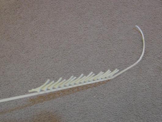
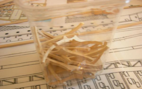
I keep a few handy to use as glue applicators, and to mix up cans of wood stain. Other than that, they're too irregular to be of much use.
-
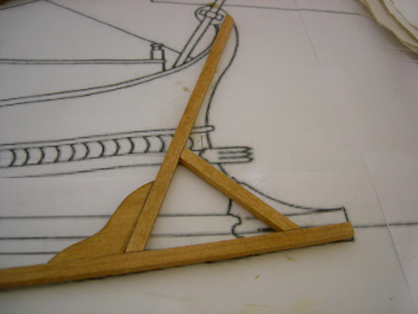
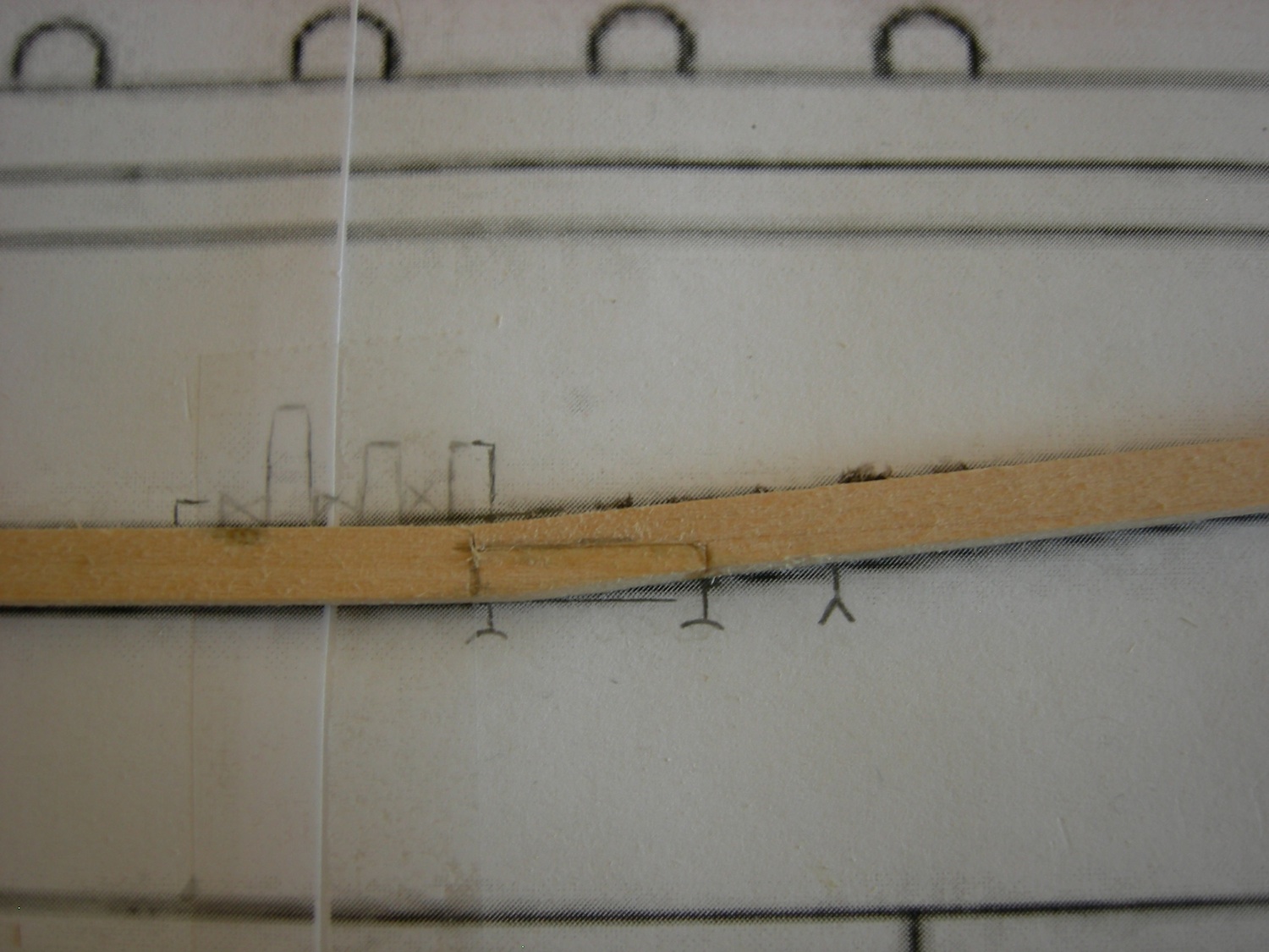
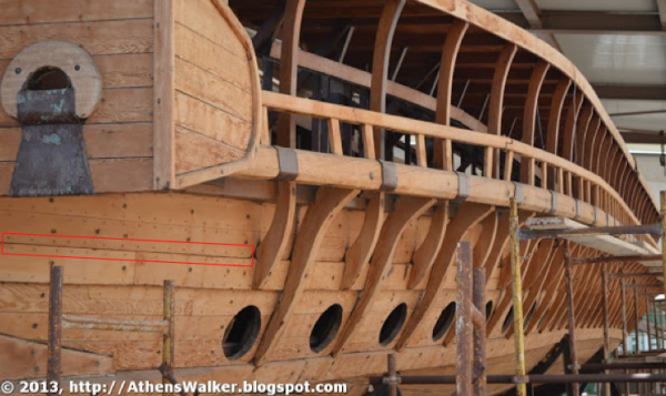
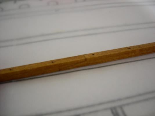
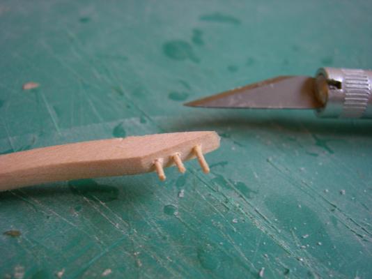
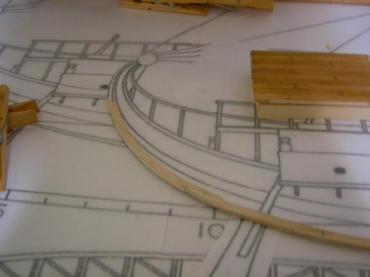
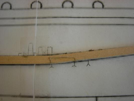
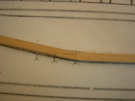
I continued to put off cutting floors today, since I came down with a cold, but later in the evening I managed a little work of the fore assembly. The curve will be filled out later in the build. I also did a little experimentation with fake treenailing detail. The rings are 0.7mm across, which translates to about 1.3" (33,6mm) at full size. Since this was just a test piece, I wasn't too careful with the spacing. I'm unsure as to whether or not I want to show the mortise and tenon joint dowels on the hull. There somewhat visible in this photo of the Olympias (inside the red box), but I don't know if it would make the model look too "messy." If I do add this detail, it will be done with a pounce wheel, so it will be much more regular than on the test piece. Also note that the larger treenails holding the ribs to the inside of the hull are much darker than the surrounding wood. I'm not sure if I'm going to try to duplicate this, or just use the method shown on the test piece above on the hull as well as the deck. Even using colored putty to fill holes is much more time consuming than simply making an impression in the wood. As you can see, there's a lot of uncertainty at this point in the build. Hopefully I can determine what to do with the detailing through some more tests, but in the meantime, suggestions/opinions are welcome.


-
Your planking looks good so far. Don't worry if some of the planks are cracked-- the oars will hide that better than might expect. How do the instructions tell you to make the oar ports?
-
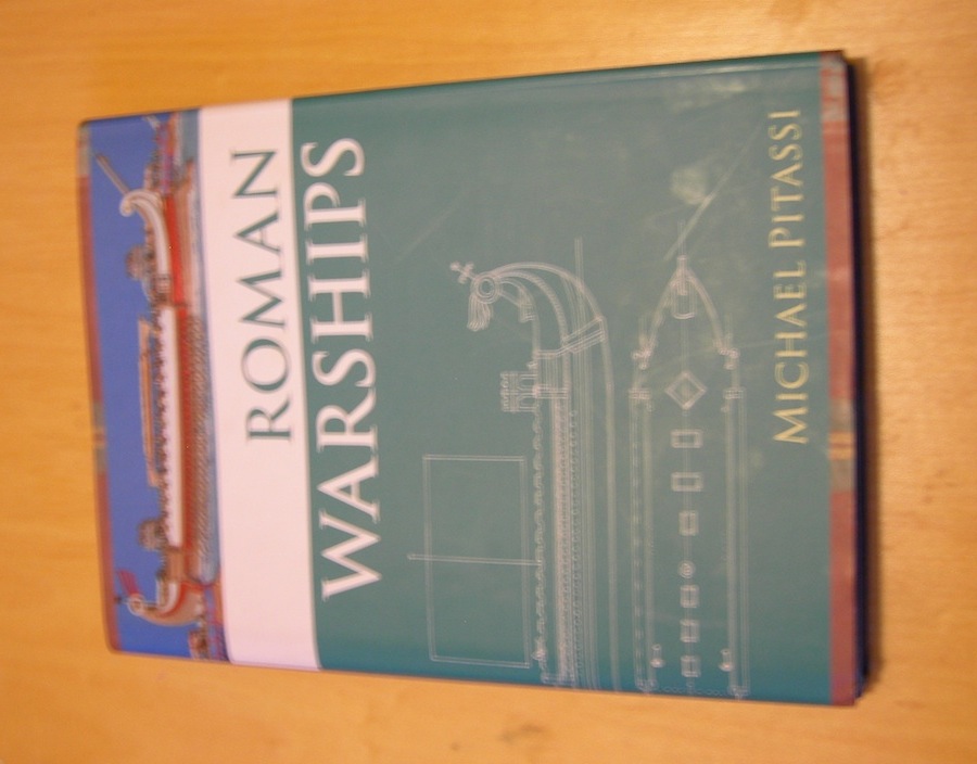
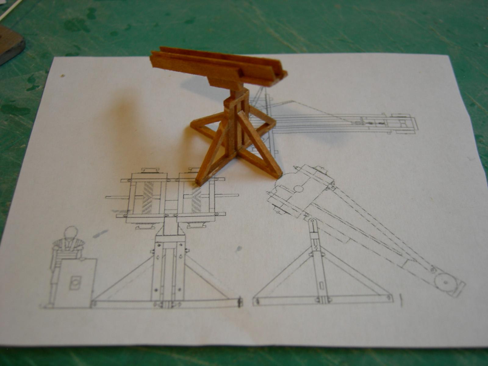
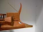
Thanks Omega! Vivan, I see your point about the ballista becoming its own project, and whether it functions or not certainly won't change the appearance of the model. But, in order to look right, it has to be built pretty much the same way as a real one, so the only thing needed to make it functional is some tension on the skeins and a lack of glue in a few spots. Anyways, we'll se how it goes. I didn't get any more of the floors cut today, but I did measure the plans for the first seven stern frames. Later, I removed the floors from the keel and stained it with Minwax Golden Oak. It still needs to be sanded to take off the fuzz, and recoated after that. In the interest of honesty, I confess that the scarf joint in the photo is fake. My real scarf joints don't look nearly that good. But the part of the keel that's inside the hull be barely visible (if at all) in the completed model, so it may not make any difference. Much of the ship would have been made from cedar because of its light weight and rot resistance, but the main structural members would probably have been oak. Though the type of wood used would have been largely determined by where the ship was built, both oak and cedar are common in what was the Eastern half of the Roman Empire. I also got some new research material. This book was kindly recommended to me by Chris Watton, as one of the most helpful resources in his development of the Amati quinquereme kit. (Edit: Not sure why it keeps rotating the photo; I thought I fixed it.) I've only flipped through it so far, but it looks like a wealth of valuable information. Tomorrow I'll stain the floors I've already made, and either cut out the ones I've taken measurement for or take measurements for the rest of them.

-
A little bit of progress today. I got another 6 floors made and dry-fitted to the keel. I'll probably take them off this weekend to stain them, since I need to be able to lay the keel flat to add the fore assembly. I'm planning to approximately follow the Olympias plan for this part. Next I'll be cutting the rest of the floors, which I have to draw myself from measurements of the plans, since I only have a mid-hull cross section. In the mean time, I did a little work on the ship's armament. I'm still debating whether to try to make it functional.


-
It's not quite as fragile as it looks-- the biggest danger is snapping the treenails that are holding the floors onto the keel, since they're not glued yet. Thanks. My scroll saw skills are already a little better than when I started, but I think by the time I get good at it, I'll be done cutting the ribs... I'll have to experiment more with the blade tensioning as well. For a light, I've occasionally used the lamp on my bench grinder, but it's a very noisy way to produce 60 watts of light.
-
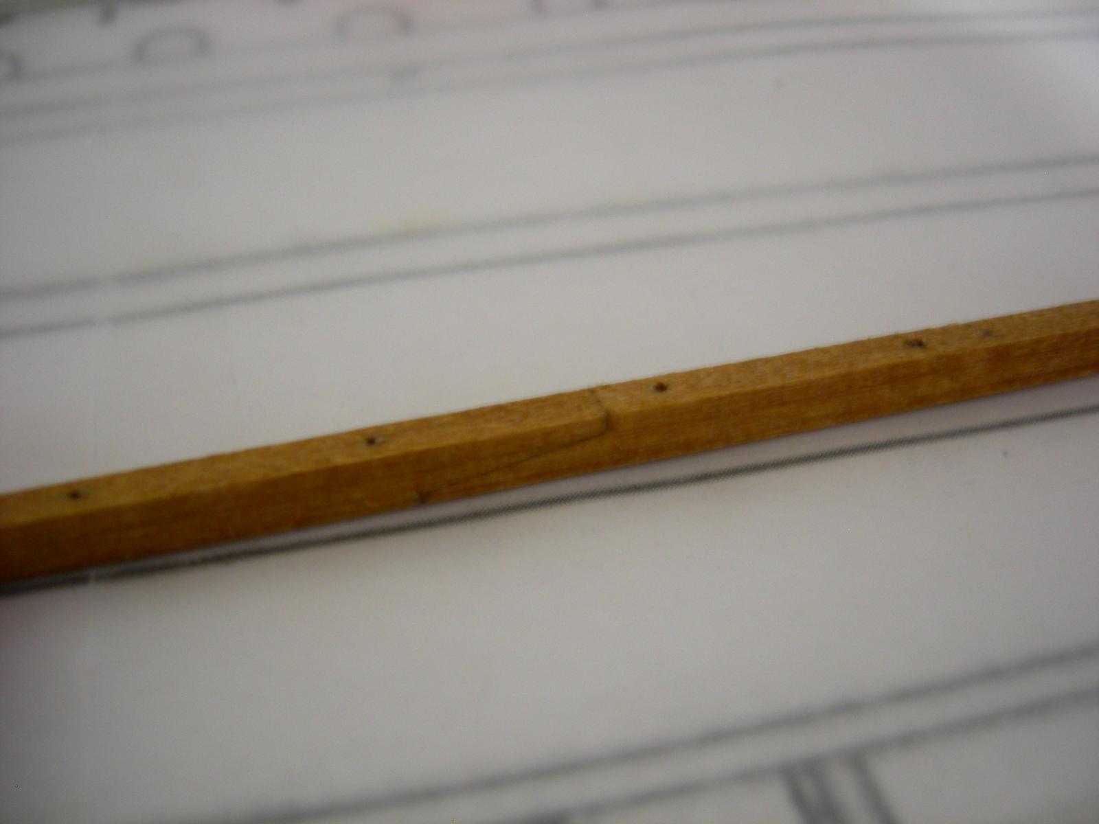
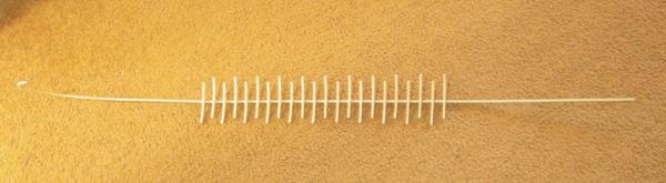
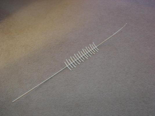
Thanks Vivian. I'll definitely need some kind of excuse for building another one-- historical accuracy will do just fine! For once I actually got as much done as I planned: mounting holes drilled in the keel, final stern section of the keel added, and eight more floors cut out. They still need to be sanded and pinned though. For the last piece on the keel, I tried a slightly different method of attachment. Instead of trying to cut another hook scarf joint, I drilled the two pieces and fitted them with 0.037" dowels, and a bit of wood glue. After drilling the mounting holes in the keel, I did a dry fit of the 16 floors that I've made so far. If you squint really hard and use your imagination, it kinda sorta looks a little like a ship! It helps that the photo's a little fuzzy. A better view of how much remains to be done:
-
Thanks guys! I often find that when I'm working on a repetitive and relatively boring part of a build, I get sort of demotivated, and I tend to wander off and start doing other things. I figure my "side project" will help with this, since it will allow to switch gears for a few minutes without leaving my workbench. The mini ship is a Fair American, built from a scaled down version of some POB plan I had laying around. I doubt I'll ever get to rigging it, since I'll probably set it aside when I get past the tedious stage of the quadrireme. I'll probably post another progress update later today, depending on how long it takes me to get my schoolwork done.
-
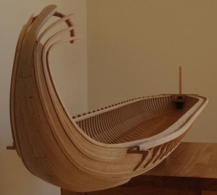
Looking good! Thanks. When I built my trireme, I was very inexperienced with planking methods, so I ran the planks horizontally up the stern, parallel to the hull planks. But, I only did this because it was easier. For my current build, I plan on following the method shown here, which is the same technique as is used on the Olympias: You can find more photos of this fantastic model here, which may be especially helpful when building the projection for mounting the ram at the bow. http://richardsmodelboats.webs.com/apps/photos/album?albumid=6414147
-
Well, I didn't get as much done today as I'd hoped, but here it is: The 16 floors that have been made so far were sanded to the proper width, and the ends cut to length. I may decide to cut the ends at an angle, though, rather than a 90˚ cut. I then drilled the bottoms of the floors and inserted 0.035" dowels, to strengthen their attachment to the keel. I also added another piece to the keel at the stern. The next piece after this will complete the curve of the "tail." Tomorrow, I plan to start drilling the mounting holes in the keel, finish the stern of the keel, and maybe also get some more of the floors cut out. At this point, I can't move forward without the use of my scroll saw. Since I live in a neighborhood where the houses are very close together, I can't use power tools late at night. So, I decided to embark on a little side project, which may or may not ever be finished.

-
This looks like a fun build; I'll be watching this as well. My first ship was a Trireme, and I have to say, there are a heck of a lot of oars! For the ram, my advice would be to build up the shape you want, and cover it with a thin brass or bronze sheet, which can be artificially given a patina. I used this method on my second ship, and I was much more pleased with the appearance than if I had cast the ram or just made it out of wood. You can see a photo here: http://modelshipworld.com/index.php/gallery/image/8078-akatos-5/ Though the lack of physical evidence of these ships can be a problem, it also means that you can make pretty much any modification you want, simply for aesthetic reasons, and no one can tell you that it is "wrong." Some characteristics may be improbable, but since thousands of these ships were built over several hundred years, there must have been a lot of different variations.
-
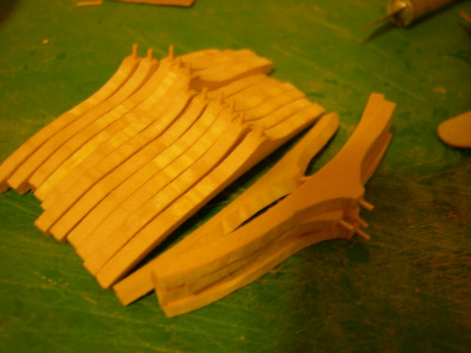
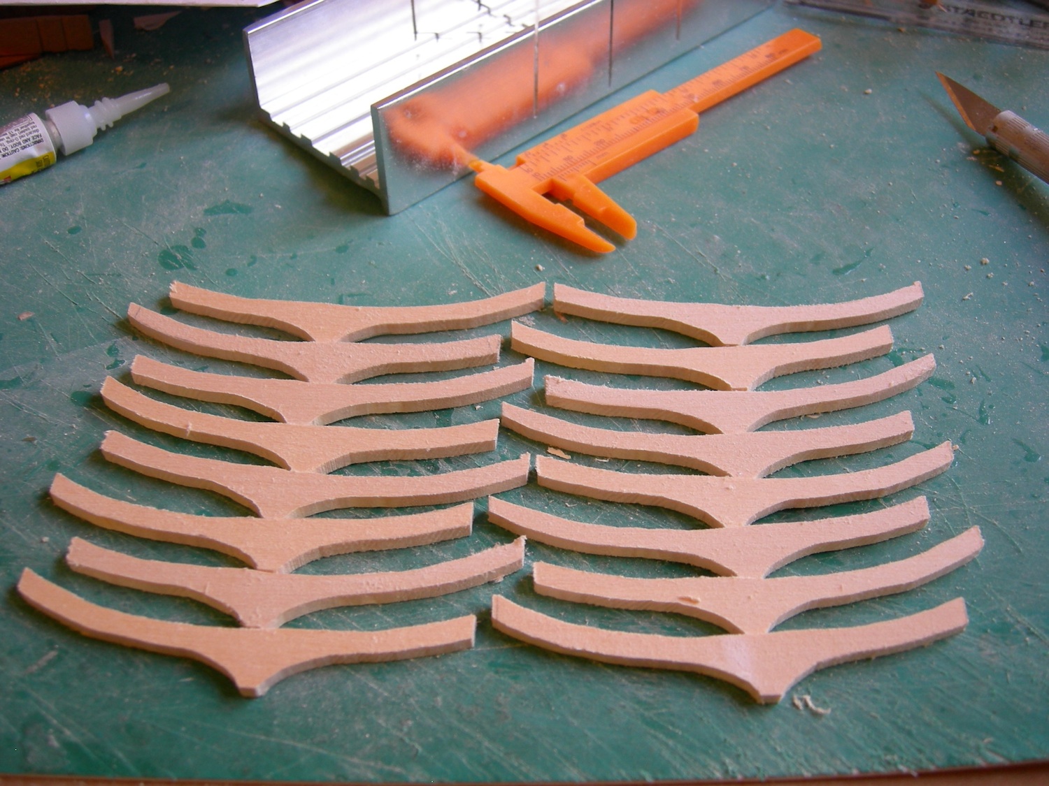
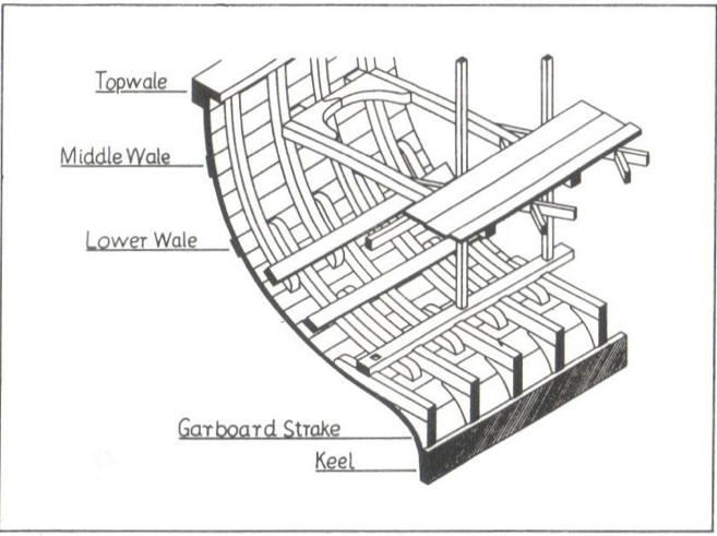
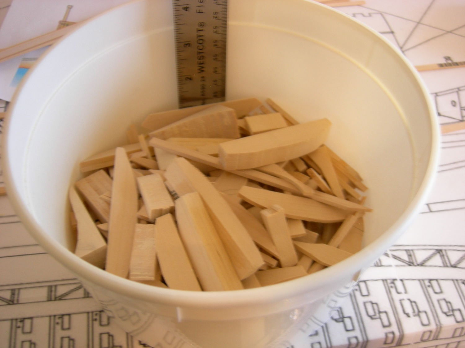
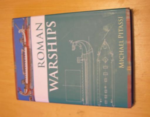
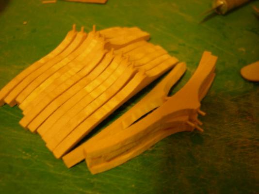
Woodrat, this danger did occur to me, and I will certainly follow David's advice. But don't worry about this being a 20-year build; I have to have it done by next February for a contest. (One of the rules is that the model must have been begun since the previous year's competition.) It's definitely a tight schedule, but I think I'll make it. Of course, this is a much larger build than my previous ships, but I've also improved a lot since then. I do remember reading that the space inside the Olympias was too cramped, since apparently the modern roars were an average of 2" taller than the ancient Greeks. Of course, the volunteer crew was also not nearly as skilled as professional oarsmen would have been, so it's not surprising that the Olympias' speed wasn't as great as an ancient trireme's. I actually haven't read Age of the Galley, though I'll be getting a copy for this build, along with Roman Warships by Michael Pitassi. Now for some progress. This build sure has been a learning experience. So far, I've learned that making things with a scroll saw is really, really hard. Here are all the pieces I've made that didn't quite turn out. I'm referring to these pieces as floors, even though they're really more like the floors and the first futtocks combined into one piece. Because of the differences in construction, I've often found that it's difficult to apply standard nautical terms to ancient ships with my limited knowledge of the subject. Anyways, I eventually figured it out, though some of the edges are a little rough thanks to my cheap blades. After cutting the ends to length and sanding the edges to even them out, they should look alright. The first thing you'll notice is that they are asymmetrical. I gather that this isn't typical of ship ribs, and to be honest I can't say why it would have any particular benefit, but everyone seems to agree that this is how it was done. I have a number of references images showing the internal structure, but this is probably the best one, showing the ribs, keel, and hull stringers. I'll try to cut at least a couple dozen more of the floors by the weekend, so hopefully I can get to attaching them to the keel sometime next week. In the mean time, here's a rather alarming picture of my bucket of waste.


-
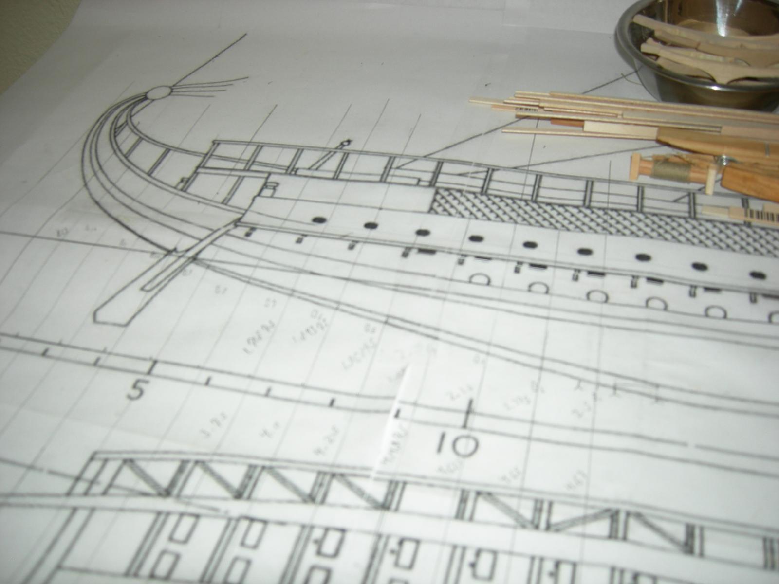
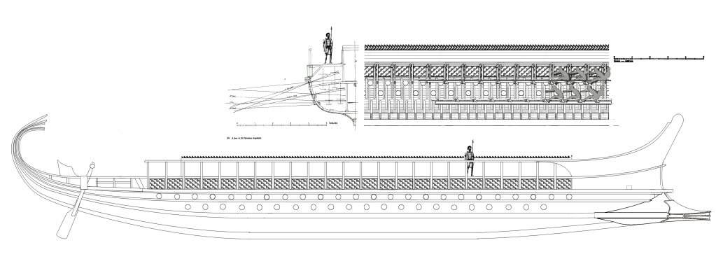
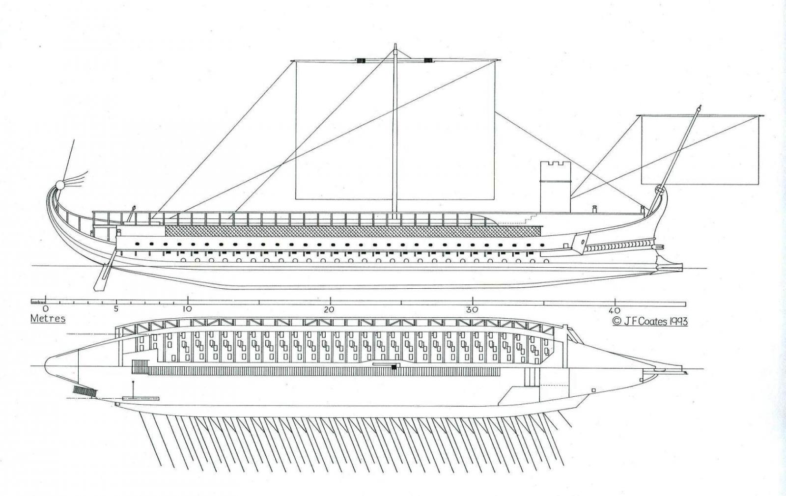
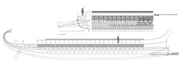
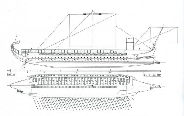
Hi everyone! I've just started my third model ship, a scratch-built Roman quadrireme, as the title says. The model is in 1/48 scale, and will have a total length of 40 inches. It will be constructed mostly of basswood, but it will be stained and sealed to eliminate any unsightly fuzziness. Additionally, a sizable portion of the hull on the starboard side will be left un-planked, in order to show the inside of the ship. I'm basing my model primarily on drawings by John F. Coats, the naval architect who designed the reconstruction of the trireme Olympias. However, he apparently never drew a reconstruction of this particular type of ship. Anyways, I'm hoping to end up with something that looks sort of like this: But, unfortunately, this isn't actually a J.F. Coats drawing; it's based on several of his drawings, but it was created by someone on another forum. Even more problematically, it gives only one cross-section, and no top view. So, for the hull, I am using this drawing of a Roman quinquereme: I also prefer this hull form, which lacks the odd projection at the front, where the ram is mounted. Due to the lack of concrete historical evidence about these ships, I have a considerable amount of leeway with this sort of thing. And, since I don't have a real set of plans, a lot of this build is going to be based on other models, illustrations, and books. So far, I haven't done much besides the keel, which, as you can see, is much simpler in its construction than that of a later sailing ship. To give a sense of scale, the keel stock is 1/8x3/16". (Don't worry, my sloppy pencil marking next to the cut will be sanded off. ) It isn't perfectly aligned with the plans in these photos, but the curves do match up. I've also completed most of the curved stern section of the keel, but I haven't got a photo handy right now. I'll try an update this log with some degree of regularity, but it all depends on my progress, of course! In the mean time, comments, questions, and especially suggestions are welcome! By the way, for those who may be interested, photos of my previous model ship can be found in the MWS gallery here. Thanks for looking! Sharpie
-
3D Printer Software
Sharpie replied to AntonyUK's topic in CAD and 3D Modelling/Drafting Plans with Software
It sounds like your best option may be to use a stamp generator, found here: http://www.openscad.org) Or, you can click the "Open in Customizer" button just above the blue download button on the Thingiverse page, and enter the coordinates into Customizer. (Using Customizer may require a Thingiverse account, but it's free and requires very little information about yourself.) After you've pasted in the coordinates, set the base thickness parameter to 0. This will give you just the pattern, without the top part of the stamp. I'm not sure about Customizer, but if you use the .scad file, it will take a horribly long time to render. Then, when it's finished, export the file as a .stl (if you're using Openscad) or download the Thing (if you're using Customizer). At this point, you have a .stl file of the original input image. You may be able to distort the angles like you described using a CAD program, but it seems to me that it would be easier to modify the original image so that the angles are correct to begin with, then go through the process described above. Note that this will only allow you to create a vertical extrusion of a 2D image. For the side engravings this should be fine, but the front curved parts might be a bit trickier. I would probably print out the front engravings as an extrusion of a flat image, then heat them up and bend them to the desired curve. I'm not really familiar with the Victory, but when I say this I'm assuming you mean something similar to this? Whether or not it's feasible to print a pattern like depends largely on how small it needs to be. I see from the link in your first post that the printer has a 0.5mm nozzle, so you may need a finer nozzle to print this kind of detail, unless the model is extremely large. It should be pretty easy to replace the nozzle though, since it just screws into the hot end assembly. Hope this helps! -
3D Printing - Not Just Yet!
Sharpie replied to dvm27's topic in CAD and 3D Modelling/Drafting Plans with Software
Since I got my printer, I've been wondering about making 3D printed parts for ship models, but I haven't gotten around to it yet, mostly due to my lack of CAD skills, though hopefully not for much longer. For model ship parts, Laywood filament might be the ideal material. It looks and feels like wood, and apparently can be cut, drilled, and sanded just like wood. I've even seen people use a script in the printing software to vary the temperatures of each layer, creating a pronounced wood-grain like effect. It's a lot more expensive than PLA or ABS filament, but for pieces smaller than a complete hull, you wouldn't need much. I'd certainly like to try some out at some point, maybe for things like small lifeboats that are somewhat more difficult to make or buy. Here's a link: https://thre3d.com/product/245-laywood Of course the main advantage of 3D printing is the ability to make things that aren't otherwise available. For example, I've been thinking that I might be able to sell small runs of ancient trireme and bireme kits if I could design and print a naval ram (or even sell just the ram, though I would think that would be a very niche market), which can be fairly challenging to make by hand, and isn't that well represented on existing kits.