
modelshipwright
-
Posts
299 -
Joined
-
Last visited
Content Type
Profiles
Forums
Gallery
Events
Everything posted by modelshipwright
-
 Good luck with your build of the Sovereign. Bill
- 382 replies
-
- 1
-

-
- sovereign of the seas
- carving
- (and 1 more)
-
Thanks for your comments. I use a professional dental drill that was given to me by a good friend who is a dentist. It operates at speeds from 0-20,000 rpm and the speed at which I carve varies all over that range but primarily at the high end. The burs used for carving are standard high speed steel burs from companes like Grobet. Hope that helps, Bill
- 382 replies
-
- 3
-
-
- sovereign of the seas
- carving
- (and 1 more)
-
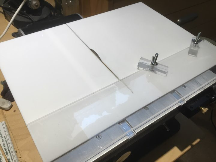
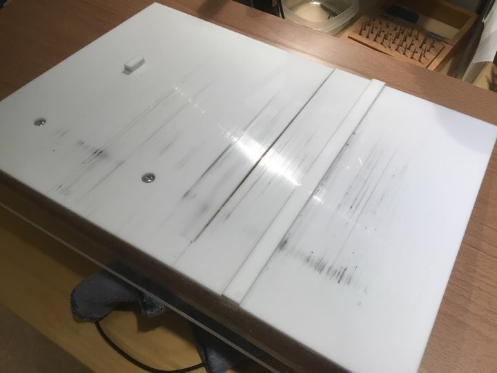
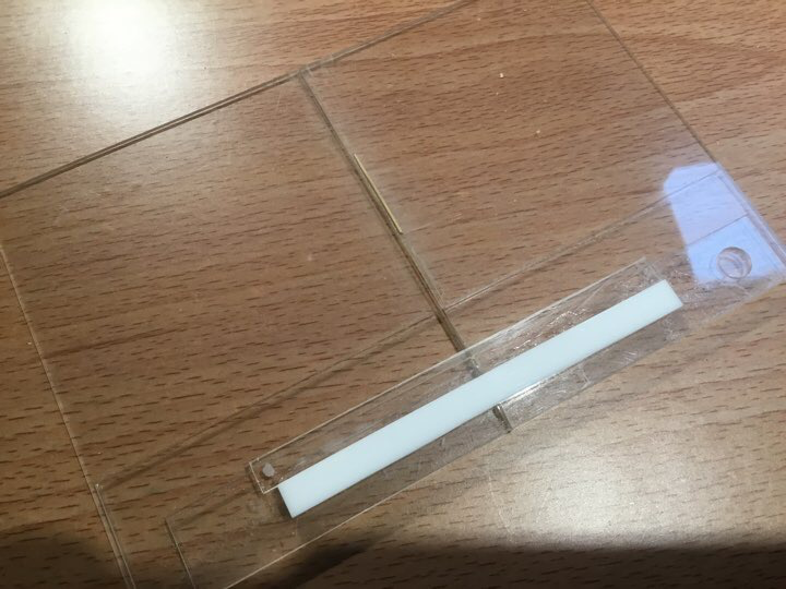
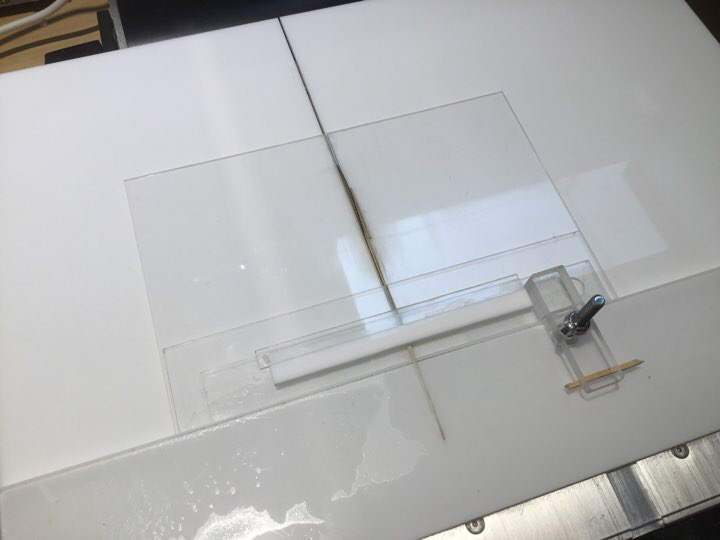
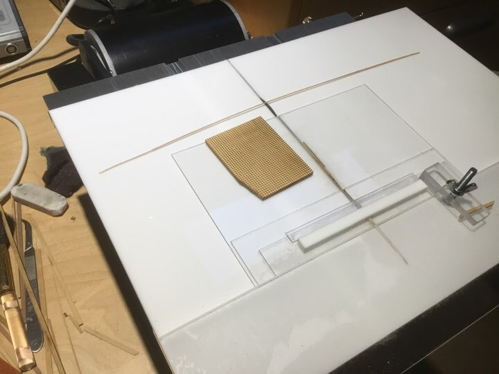
Here is a series of pictures of the fixtures used. The first photo is of the sliding table fixture sitting on the Byrnes saw. The next photo is of the underside of the same fixture. It shows the strip of acrylic glued to the underside of the table. This strip is the same width as the table saw slot and guides the sliding fixture back and forth. You can also see the countersunk screws that are used for the two clamps shown in the first photo. Additionally there is a piece of acrylic glued to the underside that acts as a stop when sliding the table forward. If you slide too far you will cut the fxture completely in half. It stops on a screw that is mounted in the edge of the table saw table at the back right corner. The next photo is of a secondary jig that is used to cut the slots in the wood. It has a piece of boxwood glued to it at the same distance from the blade as the blade thickness, in my case 0.032”. It guides the block when taking cuts. The strips of acrylic glued on top of each other at the bottom of the photo are strengthening strips to prevent the fixture from being sawn in half. The last photo shows the small fixture clamped to the sliding table fixture ready to cut slots. You adjist the blade height to be the same as the slot width so that later, strips of 0.032” boxwood can be laid into the slots to create the grate. I hope that shows it clearly as acrylic does not photograph well because of shine from the lights. If you have any questions, please ask. More to follow.........
- 382 replies
-
- 8
-
-
- sovereign of the seas
- carving
- (and 1 more)
-
Recently I have been fabricating deck gratings and found it very frustrating to align the fixture on my Byrnes saw table. The fixture consisted of a piece of aircraft plywood with a strip of boxwood the width of the slots I wanted to cut spaced an equal distance from the blade. The fixture is clamped to the saw table. To cut the slot you slide the piece of wood along the guide indexing the piece on each of the new slots. You repeat the process at 90 degrees to create the grid. The issue is that if the fixture is not absolutely square with the saw blade, the slots start to fan out. :-( A good friend and modeller helped me by fabricating a sliding table jig that is always square to the blade as it is aligned in the table slot. A small fixture similar to the one described above is clamped to the sliding table and the wood is positioned on the fixture. Each cut is achieved by pushing the sliding table across the blade. Each slot is absolutely square as the photos below will attest. More to follow........
- 382 replies
-
- 7
-
-
- sovereign of the seas
- carving
- (and 1 more)
-
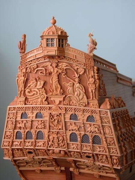
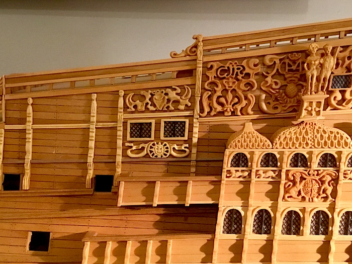
The following photo shows two new carvings and also structural divisions to divide off the area for the individual carvings. The first carving below the two rectangular windows shows the sun radiating from the centre with ribbons on the top sides. The second carving is above the windows and has a harp in the middle with a crown on the top. More to follow.......
- 382 replies
-
- 9
-
-

-
- sovereign of the seas
- carving
- (and 1 more)
-
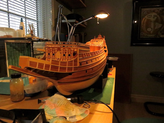
Well, the move and the months of renovations in our new home is finally over. The shipyard officially re-opened yesterday and I was able to relax and contemplate the work ahead on the Sovereign. When setting up the shop, it quickly became apparent that I had forgot where certain things were packed and it took awhile to find items to get them sorted and away. So many boxes............ As I got down to work, I found that my multitool drill was not working as the power cord was frayed and broken where it entered the end on the unit. The first work in the yard was to take it apart and re-solder the cord. With that complete I started work on the port side where work to divide the hull into sections to house carvings is needed. More to follow.......
- 382 replies
-
- 8
-
-
- sovereign of the seas
- carving
- (and 1 more)
-
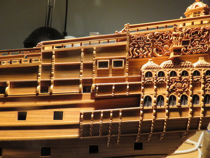
Now the ebony dividers are on the windows and they are mounted on the hull. Next is the carving below the windows. More to follow.......
- 382 replies
-
- 8
-
-
- sovereign of the seas
- carving
- (and 1 more)
-
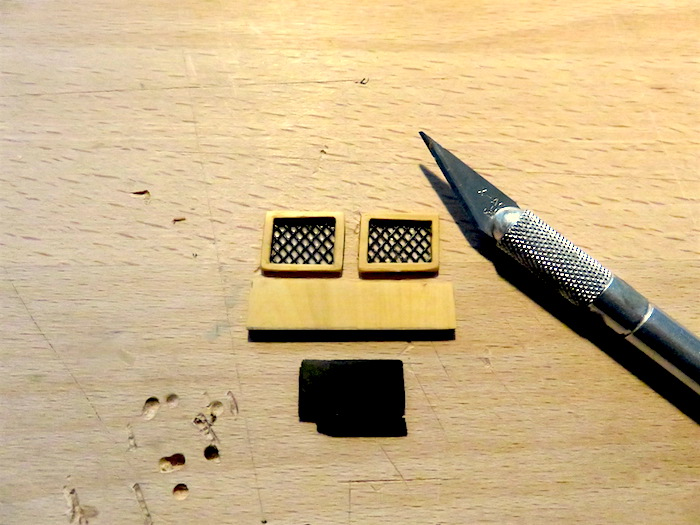
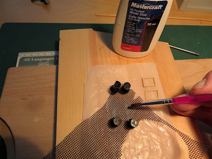
Next, I cut out the pieces of screen to form the windows and glued them to the back of the frames as shown in the next photo. The next step is to attach some small pieces of ebony to create two panes of glass in each frame. The piece of Boxwood below the windows is for a carving which goes under the windows on the hull. More to follow........
- 382 replies
-
- 5
-
-
- sovereign of the seas
- carving
- (and 1 more)
-
This gives a realistic looking glass look to the diamond shapes. Then you can cut out the pieces to mount to the back of the window frames and then onto the hull. More to follow..........
- 382 replies
-
- 3
-
-
- sovereign of the seas
- carving
- (and 1 more)
-
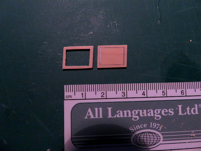
As a break from dividers I started the fabrication of two oblong window frames from Boxwood that go in a space on the port side that is near where the dividers go. First I cut them to size on the table saw and angled the ends to suit the rake of the hull. Then drilled holes in the inside corners of the window area and removed the interior wood. Next the interior window edges were filed flat. The following shows the window before and after removing the interior wood. More to follow.........
- 382 replies
-
- 4
-
-
- sovereign of the seas
- carving
- (and 1 more)
-
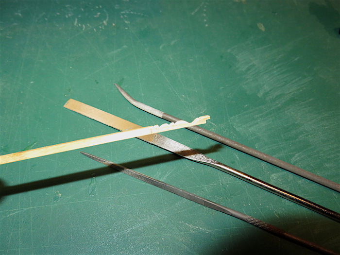
In a previous post I illustrated the method of scraping a piece of Boxwood with a straight edge razor blade to obtain a profile. As an alternative, you can use diamond and rifler files to create a profile. The following picture illustrates how a profile was formed using a round rifler file, a triangle rifler file and a flat diamond file. All the shapes shown in the profile were made with these three files. It is an acceptable way of producing these intricate dividing sections for the hull. More to follow.......... All comments gratefully received.
- 382 replies
-
- 4
-
-
- sovereign of the seas
- carving
- (and 1 more)
-
A re-carved dividing sculpture is mounted on the hull with a second dividing sculpture as well. Still have not found the original. More to follow........
- 382 replies
-
- 8
-
-
-
- sovereign of the seas
- carving
- (and 1 more)
-
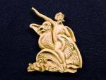
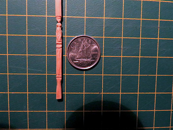
I have lost a completed carving in The Modellers Abyss and after a complete workshop cleaning including vacuuming with a nylon stocking over the vacuum hose, I failed to find the carving. It is gone forever. I started a new replacement carving today and the following picture showing it in progress is proof that it actually exists just in case the Abyss swallows it as well. It is one of the dividers that section off the hull to frame more carvings to come. No doubt, that after I complete this carving, the original will show up. Murphy's Law I think. More to follow...........

- 382 replies
-
- 6
-
-
-
- sovereign of the seas
- carving
- (and 1 more)
-
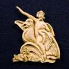
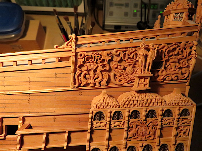
The finished carving mounted on the hull to the left of the "CR" carving More to follow...........
- 382 replies
-
- 8
-
-
- sovereign of the seas
- carving
- (and 1 more)
-
The next port side divider carving is underway. Boxwood is the wood of choice. At this scale, it is hard to get the detail necessary to replicate the form but at viewing distance, about 3 feet, the brain accepts the image just like when a painting is viewed at a distance. Up close you see imperfections. More to follow...................
- 382 replies
-
- 8
-
-
- sovereign of the seas
- carving
- (and 1 more)
-
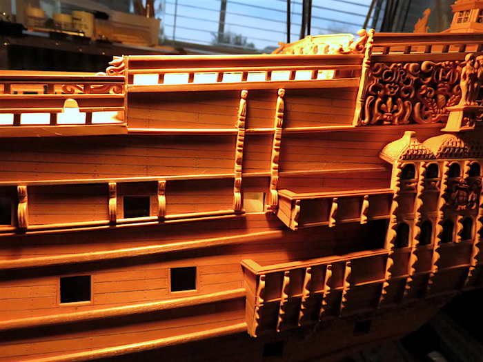
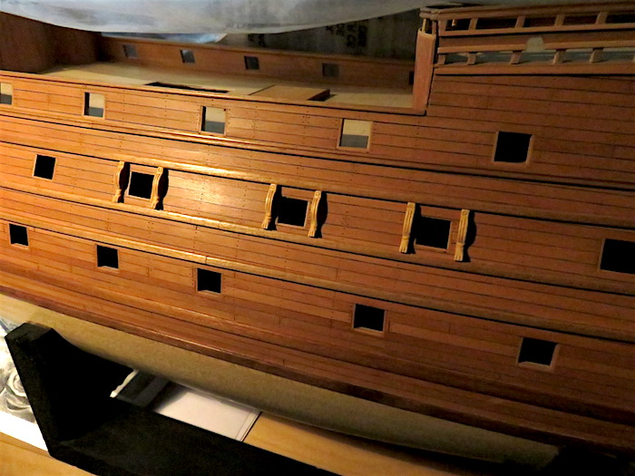
Well, I have temporarily stopped work on gratings while I await the arrival of my new Byrnes Table Saw. I think I will make a new fixture using the new saw when it arrives to fabricate the remaining gratings. Meanwhile I have been cutting off pieces from the strip I scraped in an earlier post and finishing them with decorative additions. The following photo shows them assembled to the port side upper gun deck gun ports. I had shown a few of them on the hull in a previous photo on the gun deck below this one. I was in error on that as these decorations are only on the upper gun deck. More to follow............
- 382 replies
-
- 8
-
-
-
- sovereign of the seas
- carving
- (and 1 more)
-
Working away on the other remaining pieces showing six of these mounted on the port side. More to follow...........
- 382 replies
-
- 8
-
-
- sovereign of the seas
- carving
- (and 1 more)
-
This is one of the decorations with a little added carving detail. More to follow............
- 382 replies
-
- 2
-
-
- sovereign of the seas
- carving
- (and 1 more)
-
Thanks for the explanation Dirk. I should mention that the method I used when making these gratings is meant to simulate a real grating when viewing the model from a distance of about 3-4 feet at 1:78 scale and not to represent actual building practices of the period. A simulation only, if you get my meaning. If I was building at a bigger scale I would have built them differently. The theme of my model is to present an artistic representation of the Sovereign from my minds eye. Thanks for catching that as it is an interesting point. Bill
- 382 replies
-
- 3
-
-
- sovereign of the seas
- carving
- (and 1 more)
-
Not sure I know what you mean? Could you explain it for me? Thanks, Bill
- 382 replies
-
- 1
-
-
- sovereign of the seas
- carving
- (and 1 more)
-
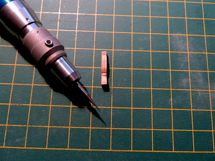
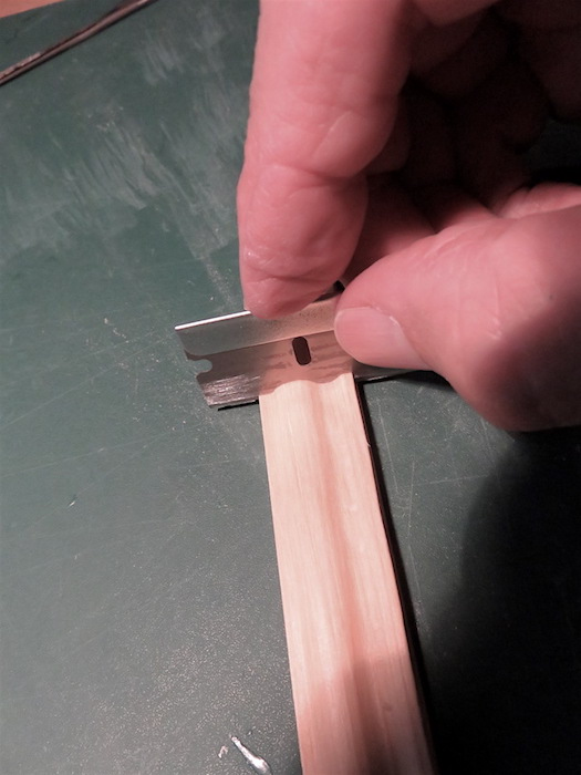
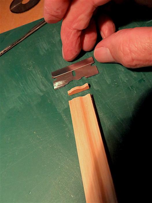
Next I decided to prepare a strip of boxwood to form the profile of sculptures on the sides of the hull separating sections that will contain more carvings. The profile is created by using a single edged razor blade and creating the desired profile in the blade so that when it is scraped along the boxwood strip, eventually you get the desired result. This photo shows the blade on the strip so you can see the profile being scraped into it. This shows one of the sculptures cut off on my table saw. Further finishing will be done to enhance the look of these pieces. More to follow...........
- 382 replies
-
- 6
-
-
- sovereign of the seas
- carving
- (and 1 more)
-
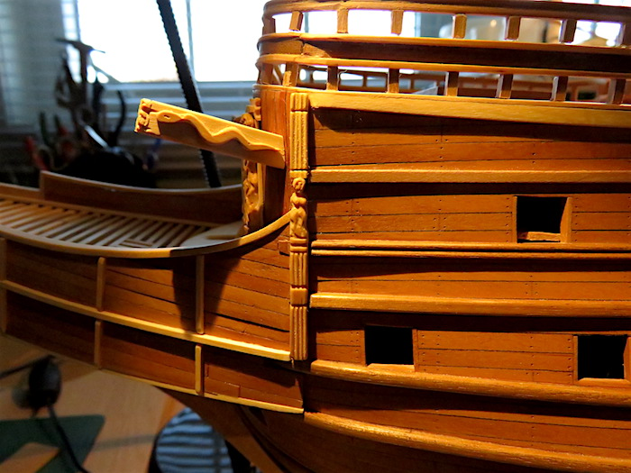
This photo shows the transition pieces between the hull and the beak from the bow. More to follow.........
- 382 replies
-
- 8
-
-
-
- sovereign of the seas
- carving
- (and 1 more)
-
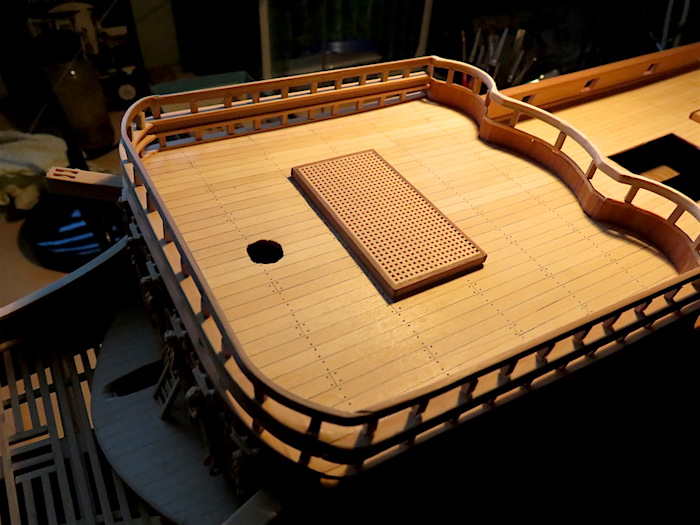
The trim pieces that make the transition from the hull to the beak are in place. The mizzen deck grate is in place after trimming the edge with african walnut. More to follow.............
- 382 replies
-
- 9
-
-
-
- sovereign of the seas
- carving
- (and 1 more)