HOLIDAY DONATION DRIVE - SUPPORT MSW - DO YOUR PART TO KEEP THIS GREAT FORUM GOING! (89 donations so far out of 49,000 members - C'mon guys!)
×


Wolfman_63
-
Posts
52 -
Joined
-
Last visited
Content Type
Profiles
Forums
Gallery
Events
Everything posted by Wolfman_63
-
I do not see it on my reference photo's. I have a photo of the Nimitz and it's there, but not in the Vinson photos.
- 82 replies
-
- 3
-

-
- carl vinson
- trumpeter
- (and 2 more)
-
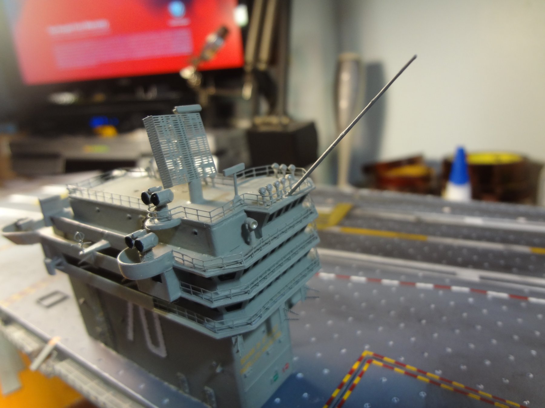
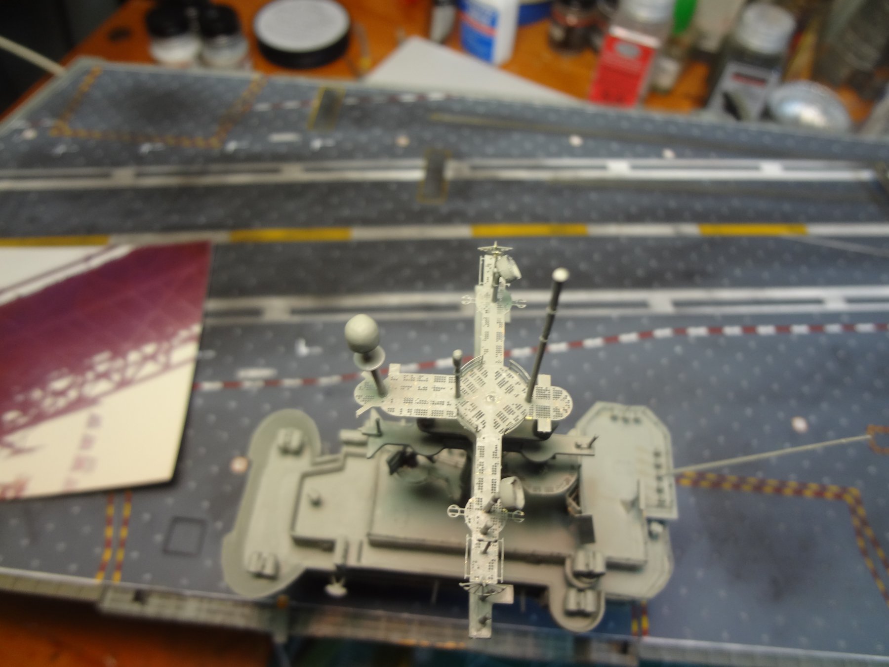
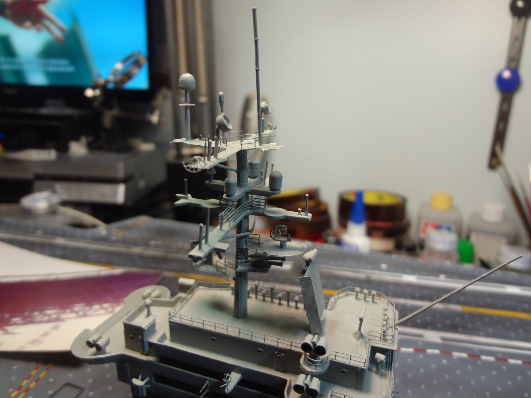
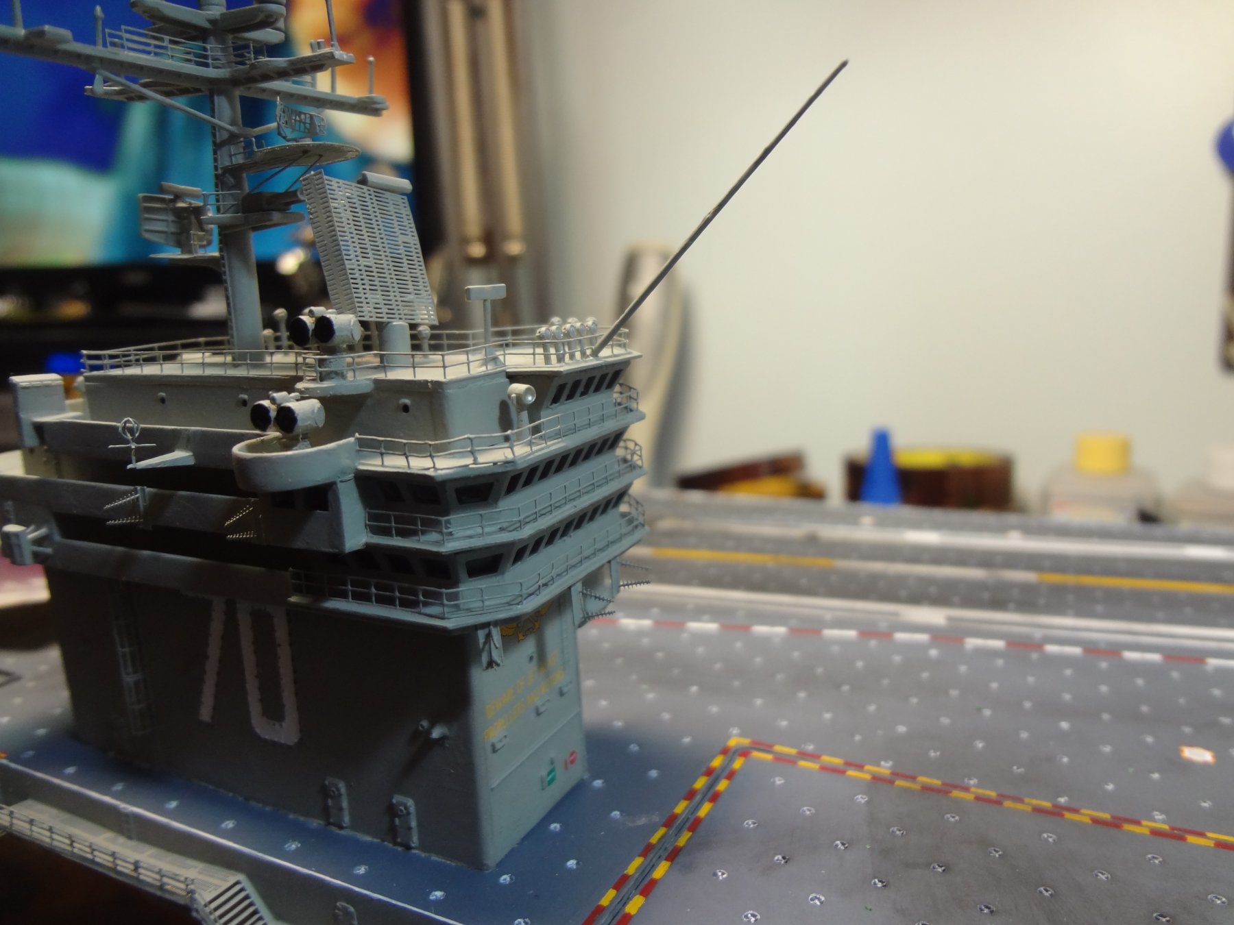
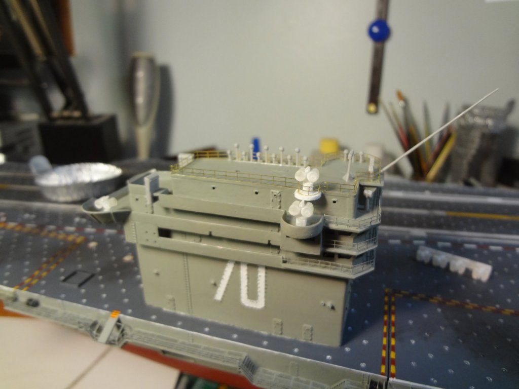
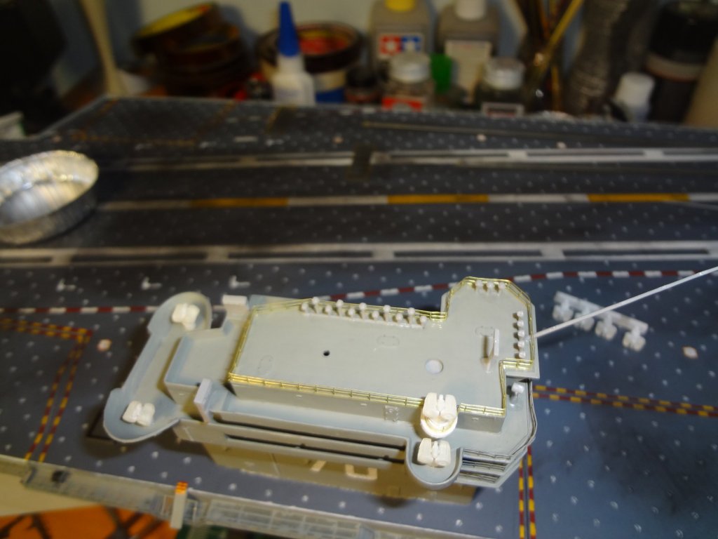
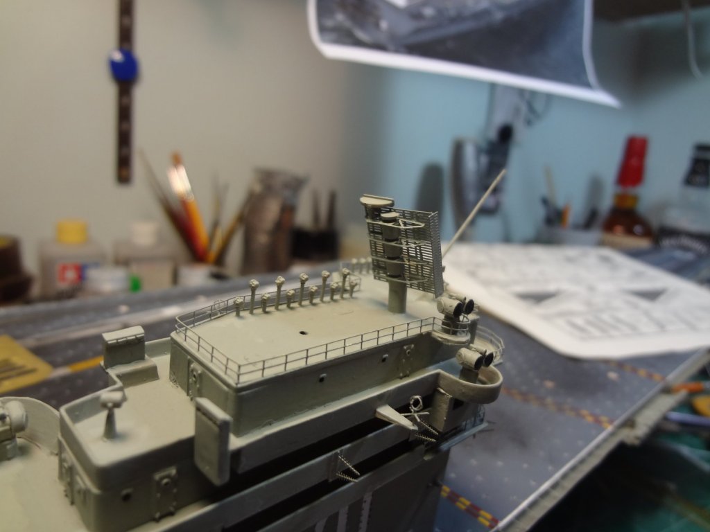
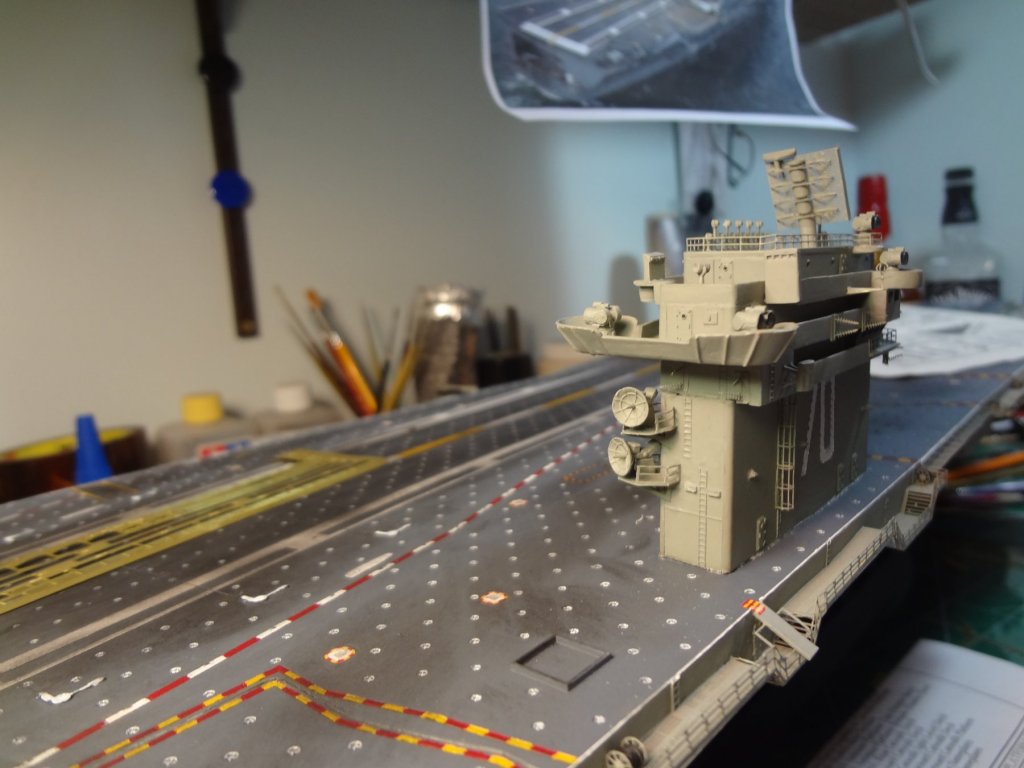
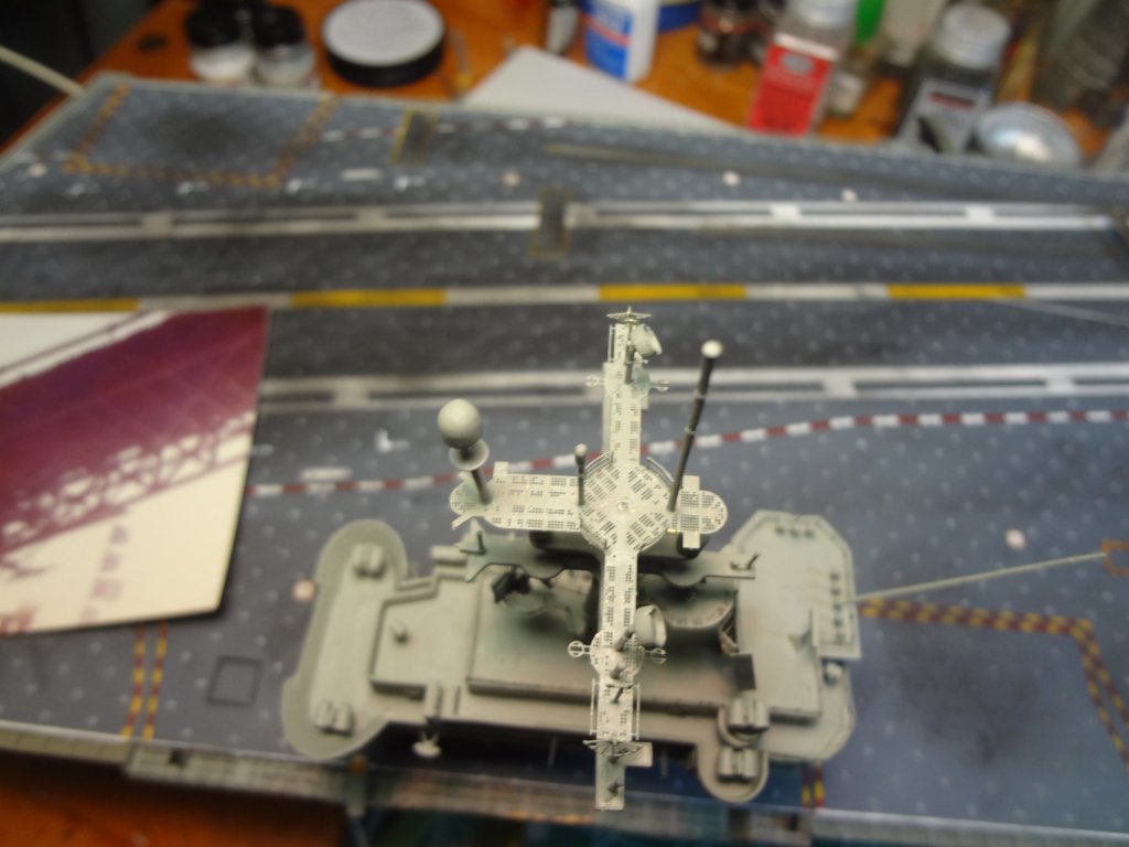
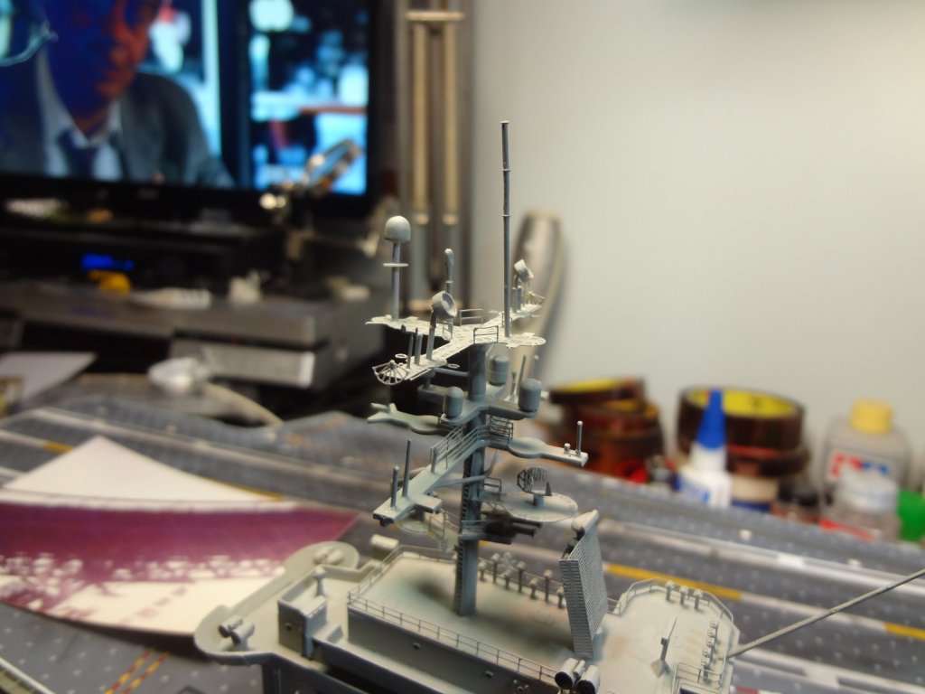
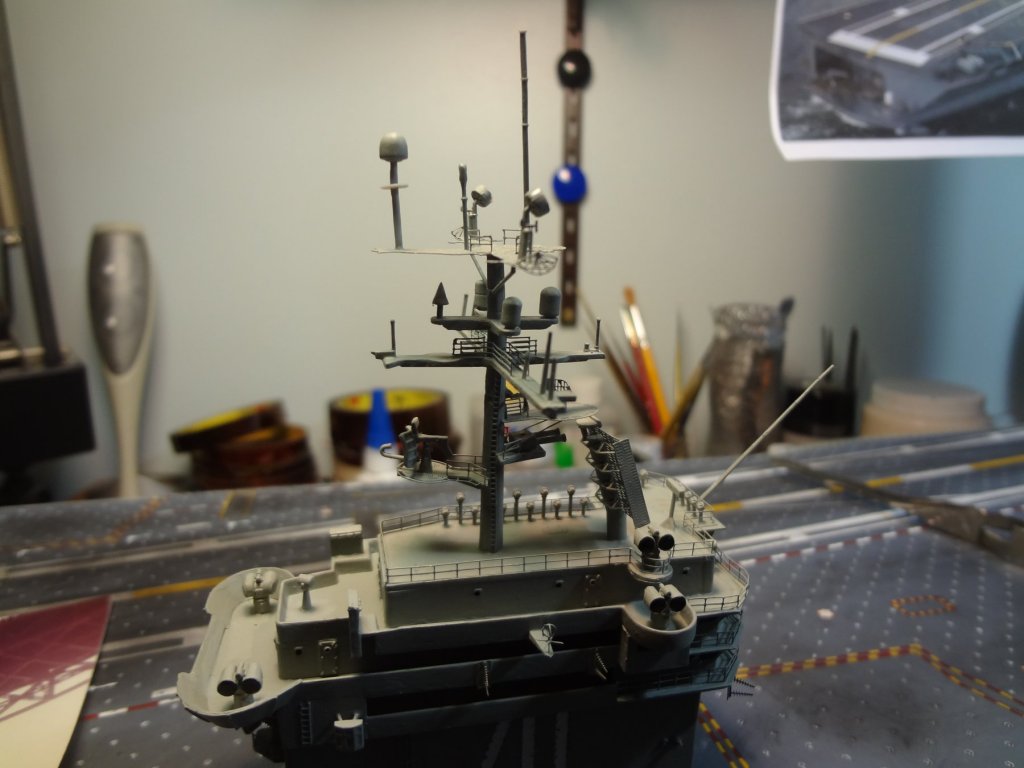
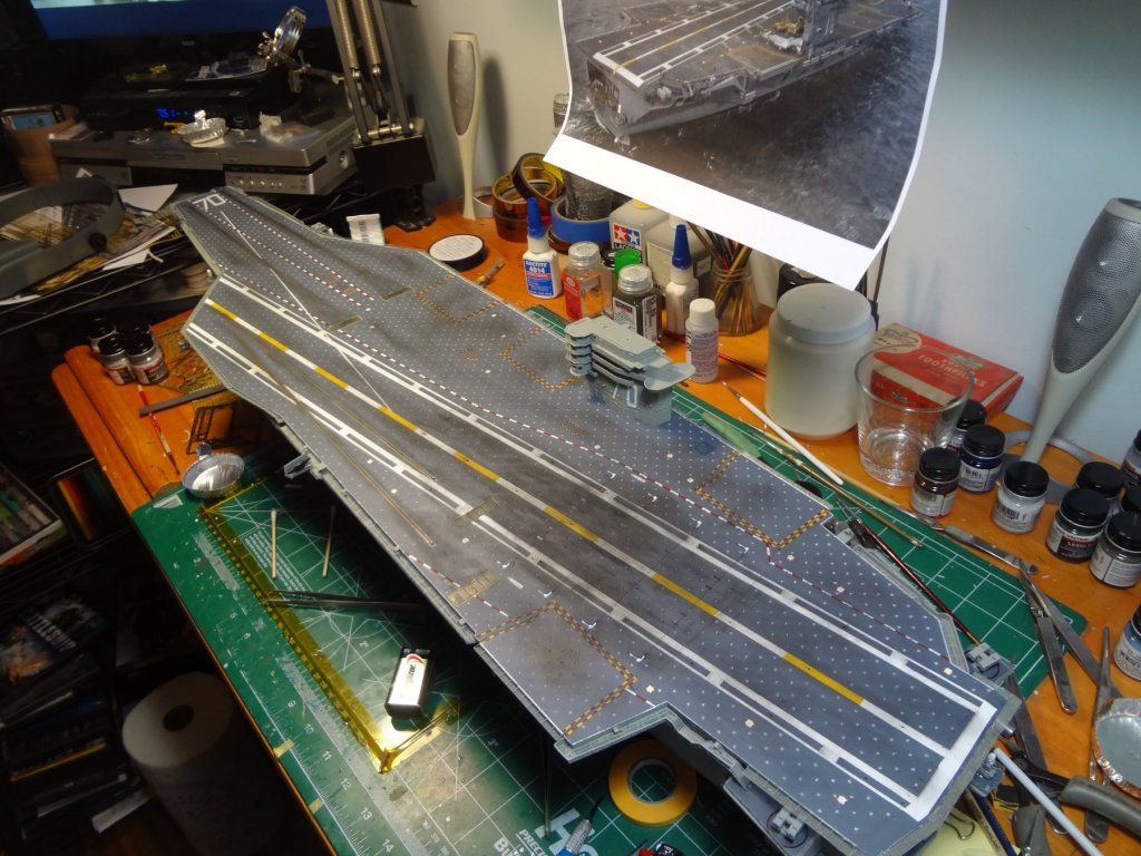
The island detailing is next. I used Shapeways Mk. 95 NSSM's and modifed the masts to the Vinson configuration. The mast still needs to be tweeked and aligned which will be done when the rigging is installed. That should now bring everyone up to date on the project. Typically I update every weekend. I am working on the rigging now then the radar tower that sits behind the island. Still need to do the whip antenna's around the flight deck and the life raft canisters. Then building many aircraft, deck tractors, and the tilly crane. I hope you have enjoyed my progress and continue to watch the build. While I have posted many photos of the progress, There are many more photo's of this build in my build album on Flickr. You can view them at https://www.flickr.com/photos/128642409@N05/albums/72157687002588814 Thanks!


- 82 replies
-
- 9
-
-
- carl vinson
- trumpeter
- (and 2 more)
-
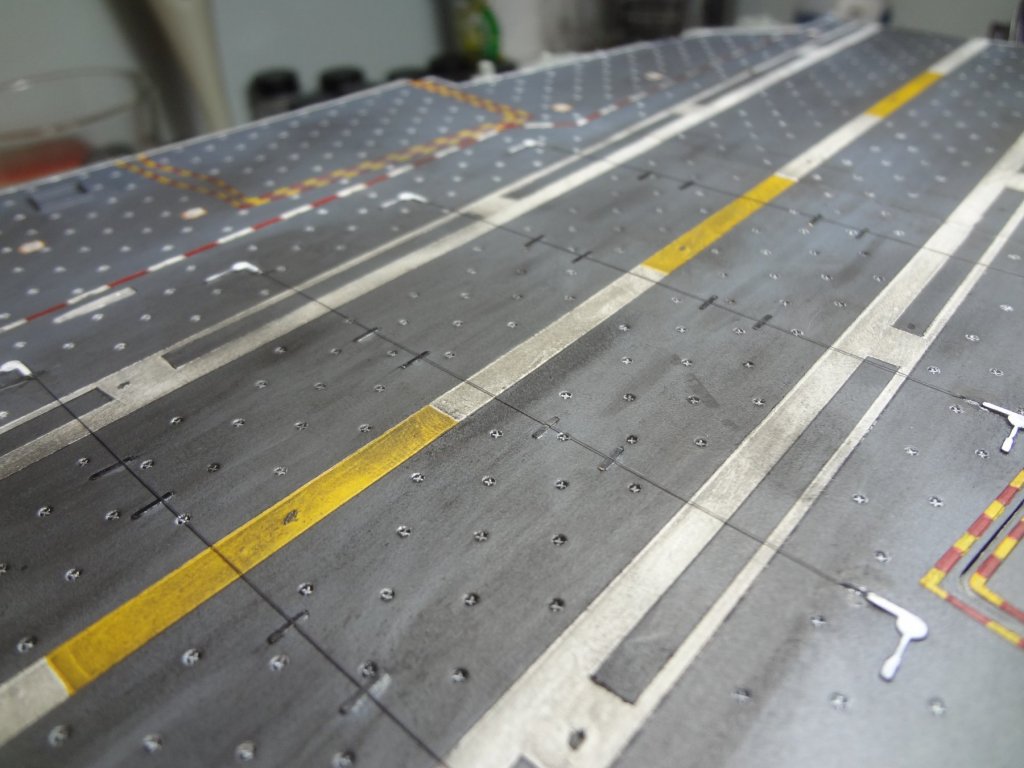
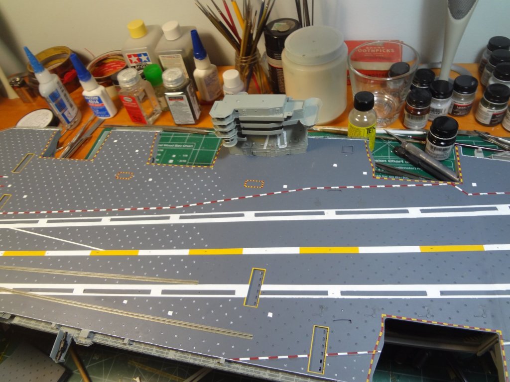
The catwalk hose reels were made. The landing wires were installed using EZ Line and the flight deck was weathered. I used black, gray, and brown pastel chalk. I first took the brown and using a balled up paper towel I rubbed the chalk on the jet blast deflectors and the area between the catapults and JBD's. I then used same method and did the area's outside the brown areas and down each side of the catapults. I then used the same method but went over the center of the JBD's and catapults with black. The then made blotches and stains around the entire flight deck. I made a large area around landing wire #3 (This is the wire that the pilots aim for as the perfect landing wire to catch). On this large area I then used eye makeup foam pads and made streaks with black and gray to represent where the aircraft touched down. Mostly near the center of the runway and extending from wire 1 to wire 4 in a diamond pattern centered on wire 3. Finally taking a makeup blush brush I brushed the surface of the flight deck from bow to stern to blend the colors and remove any excess chalk powder. It then gets a dusted spray of matte clear coat 3 times allowing each coat to dry. Then a final coat to seal it all. The dusted coats are required because if you spray a seal coat, it will pick up some chalk and give it weird streaks.
- 82 replies
-
- 8
-
-
- carl vinson
- trumpeter
- (and 2 more)
-
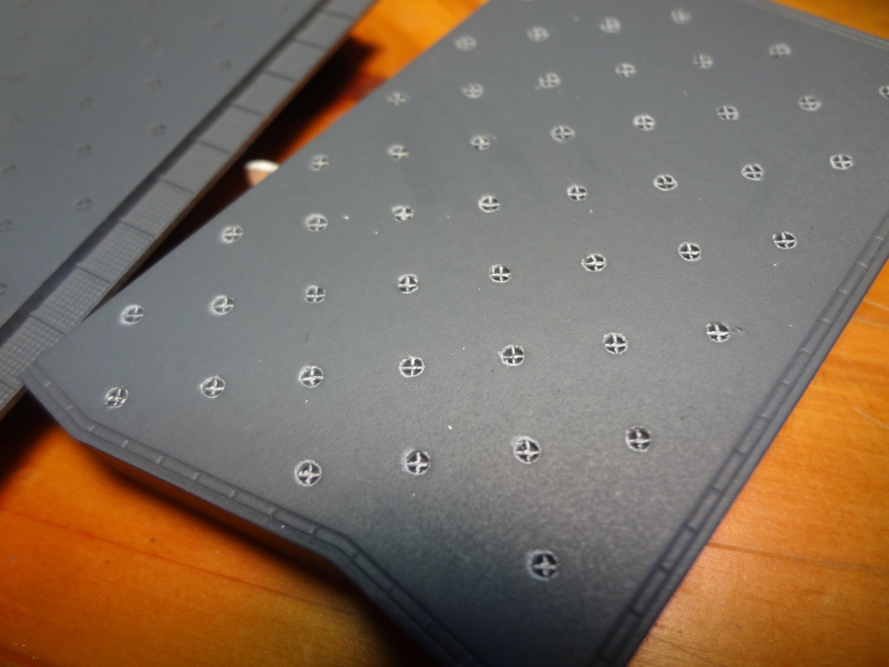
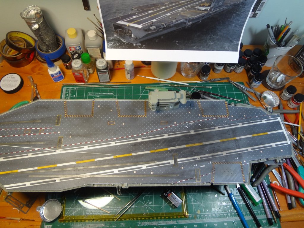
More detail painting and decals for the flight deck. All catwalks and safety nets painted. The padeyes were not painted. I actually used a Prismacolor soft lead pencil to color them then ran a pink eraser across the deck to make them look painted.


- 82 replies
-
- 7
-
-
- carl vinson
- trumpeter
- (and 2 more)
-
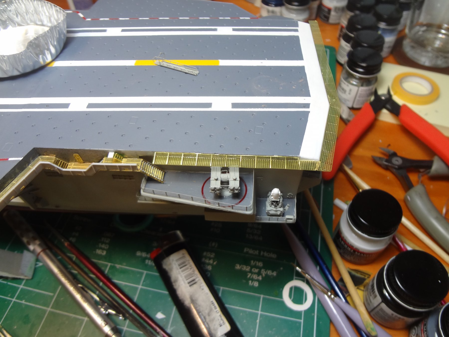
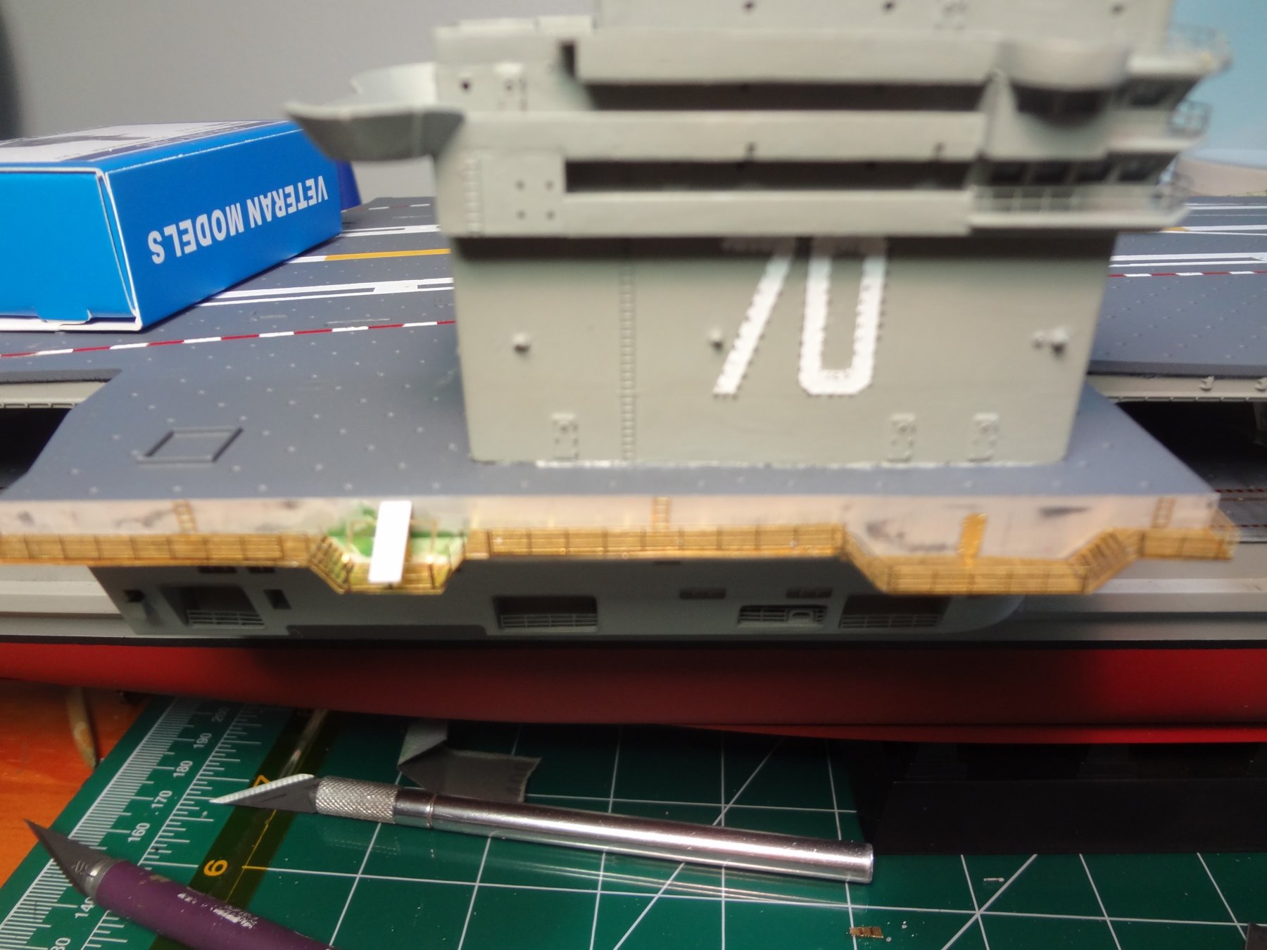
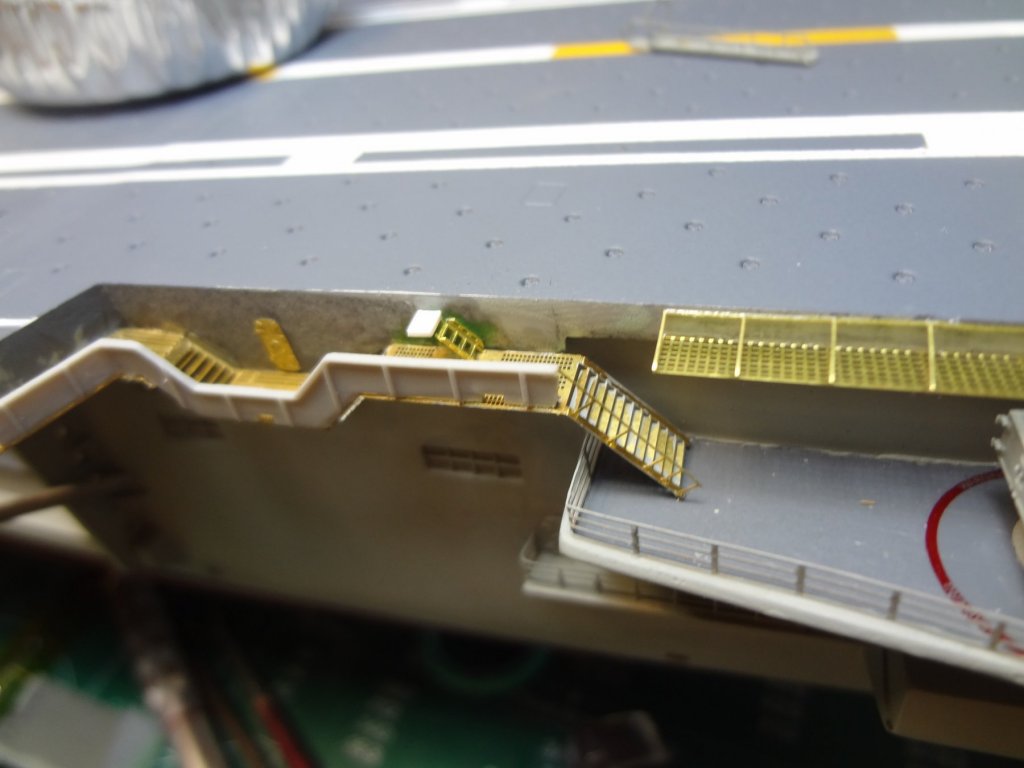
The photoetch catwalks and safety netting was installed and the Veteran Models CIWS were built and installed.


- 82 replies
-
- 7
-
-
- carl vinson
- trumpeter
- (and 2 more)
-
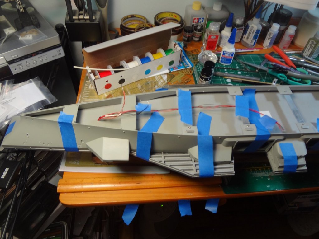
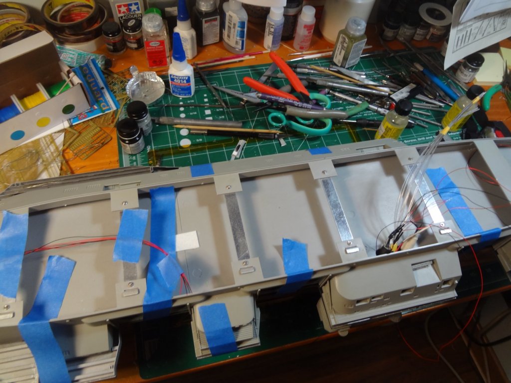
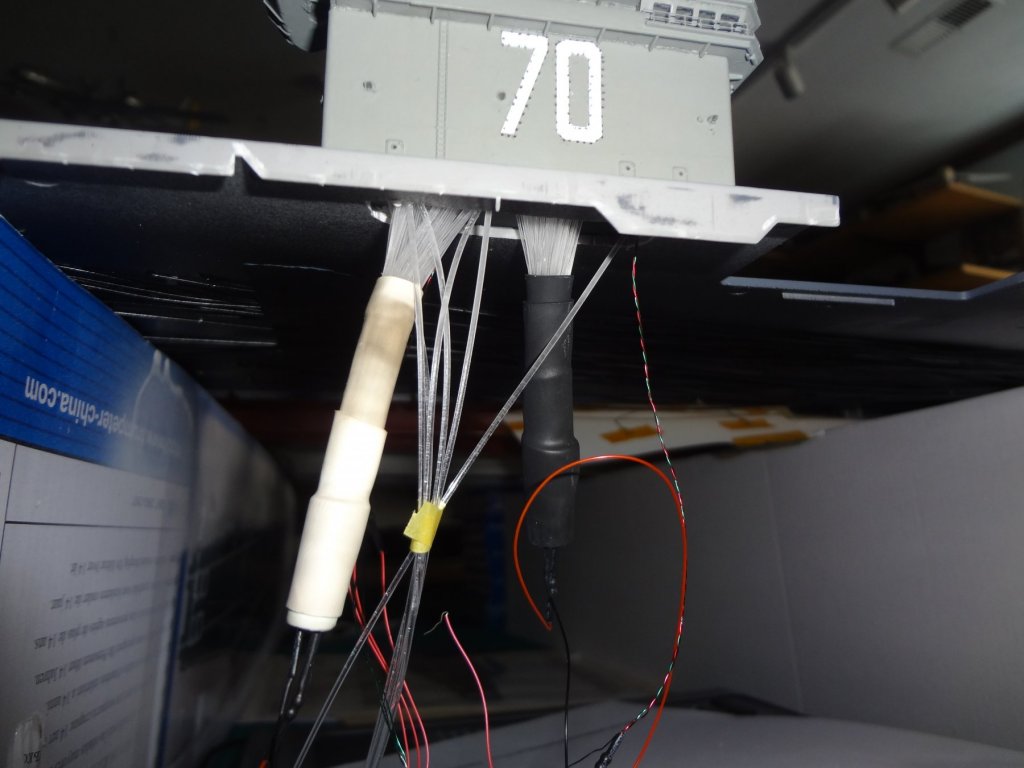
I then routed all the wiring and fiber optic lines that were being mounted under the hangar bay deck. Verified the lighting and installed the lower hull.


- 82 replies
-
- 10
-
-
- carl vinson
- trumpeter
- (and 2 more)
-
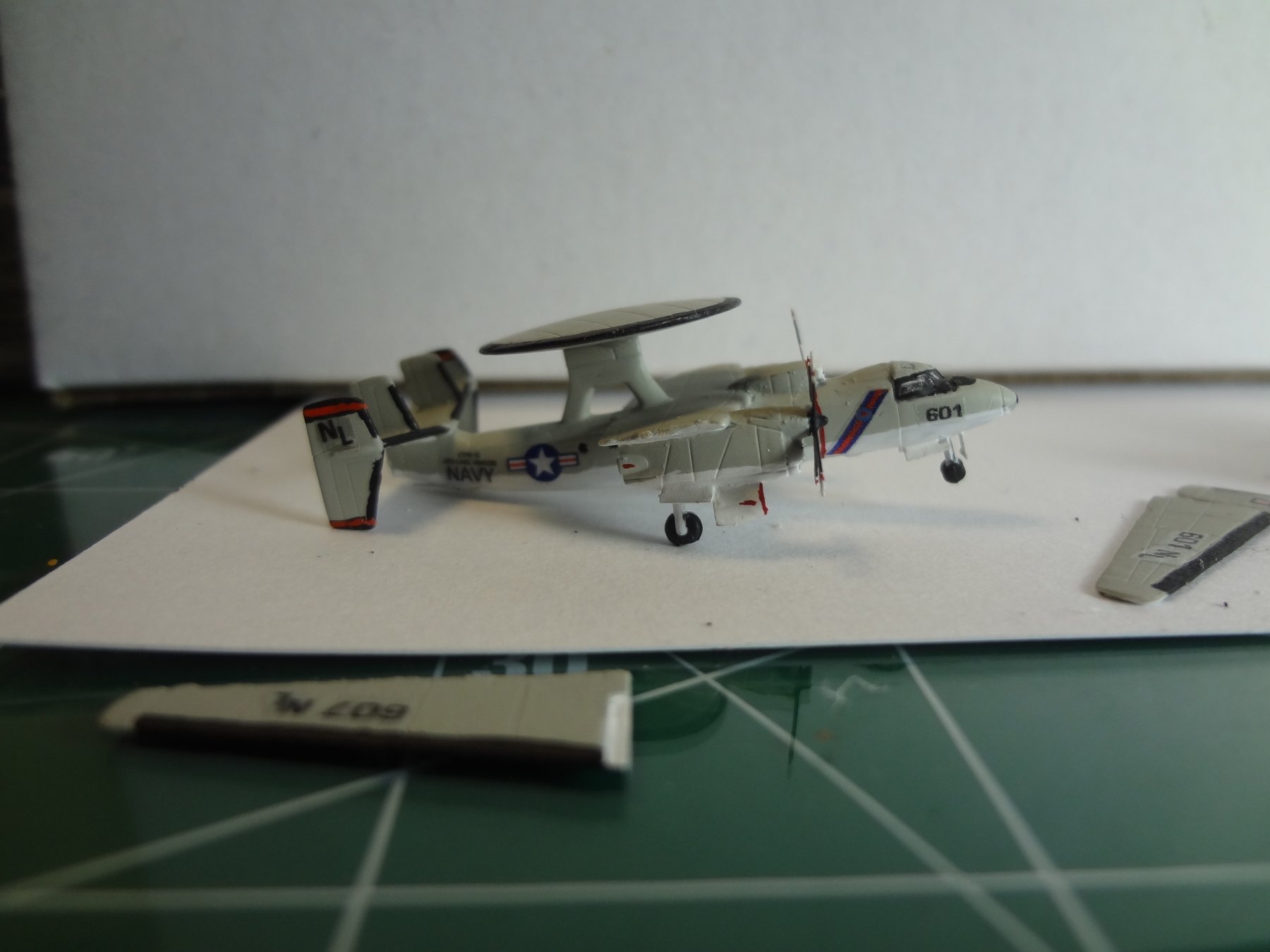
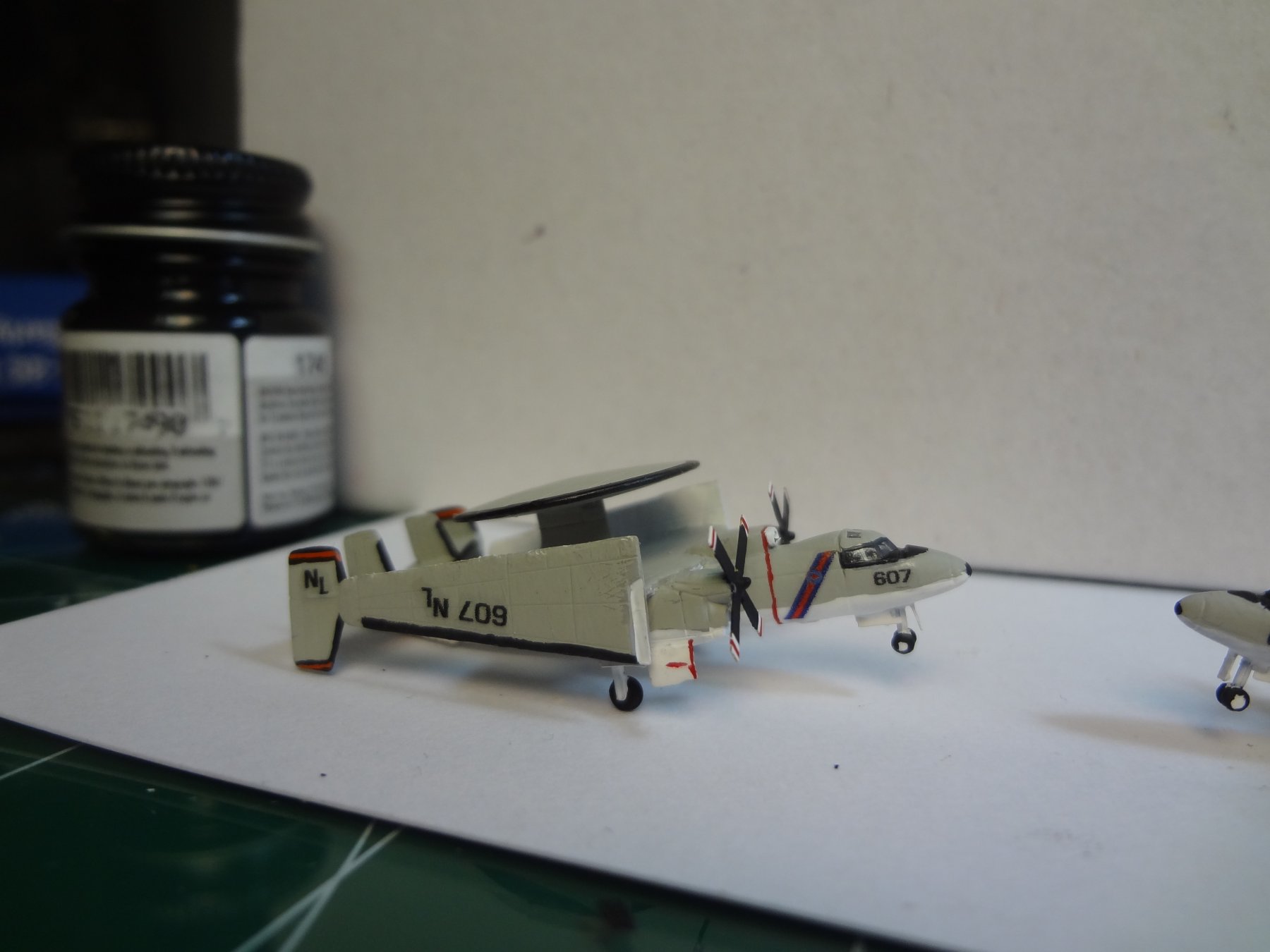
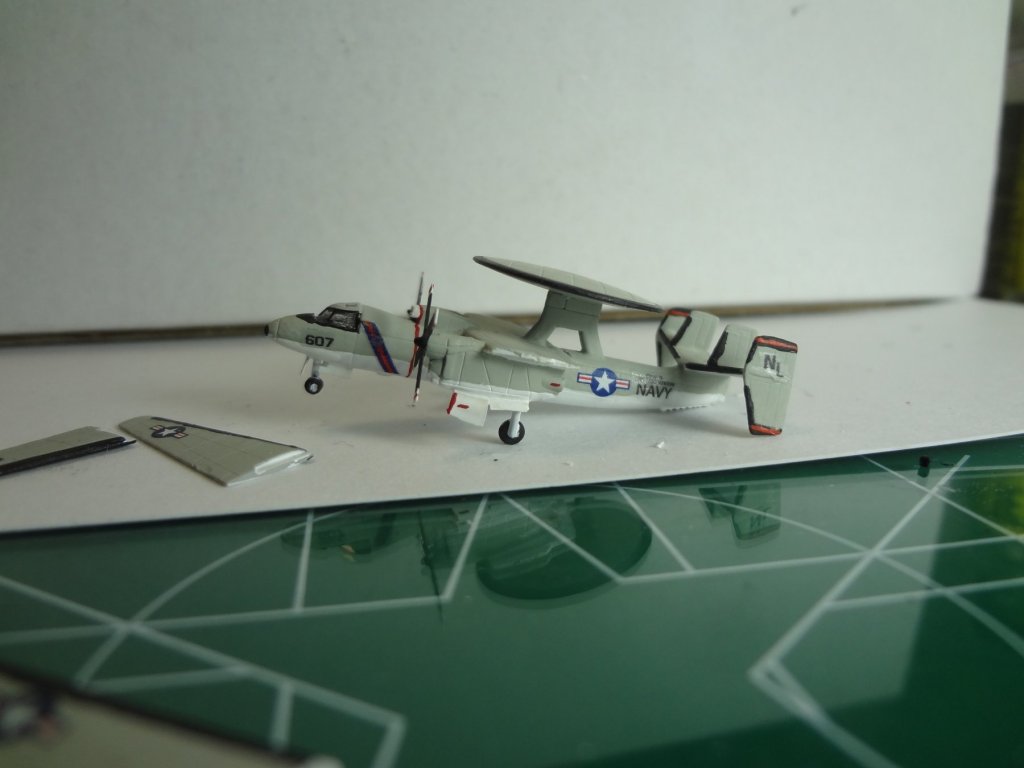
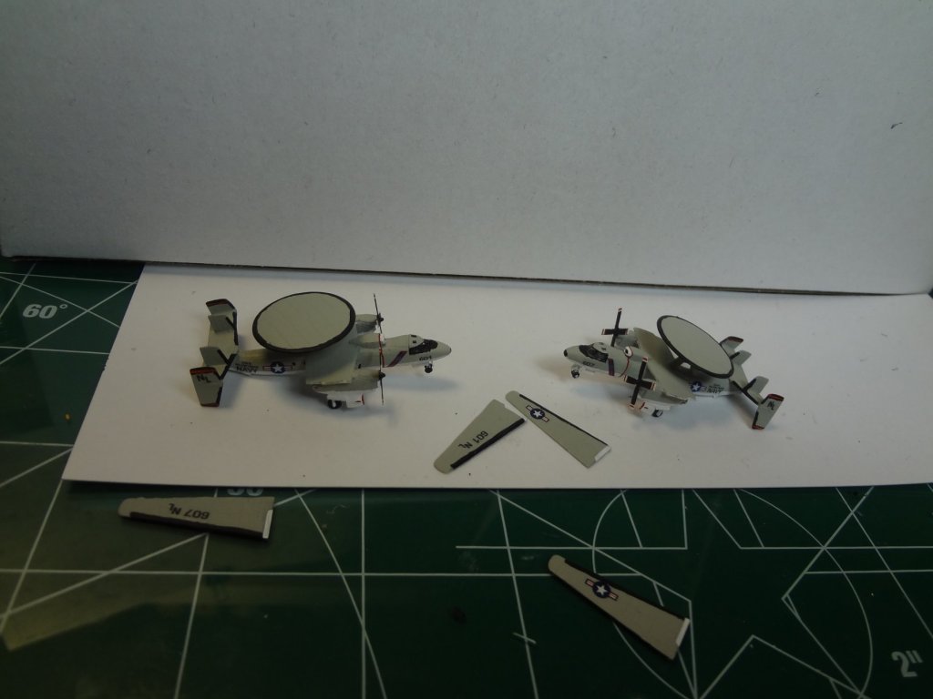
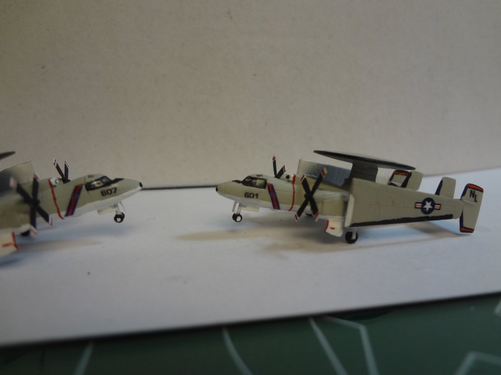
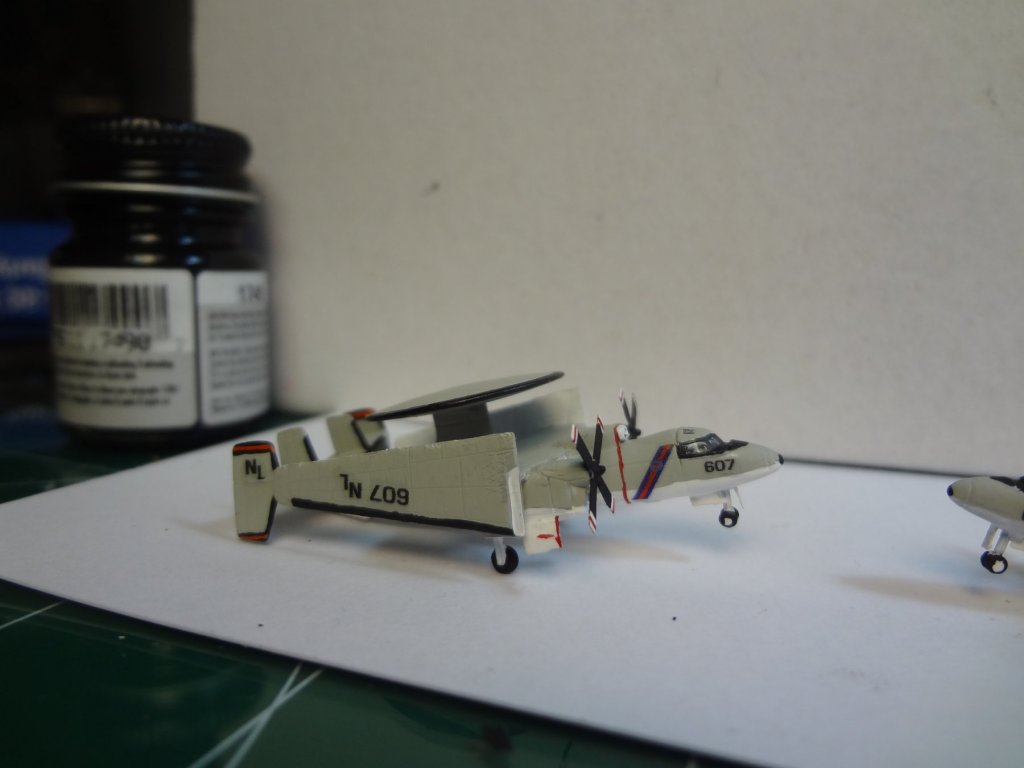
Finally the E-2C's of VAW-114. This completes all 26 aircraft on the hangar bay. All the other aircraft will be on the flight deck.

- 82 replies
-
- 6
-
-
- carl vinson
- trumpeter
- (and 2 more)
-
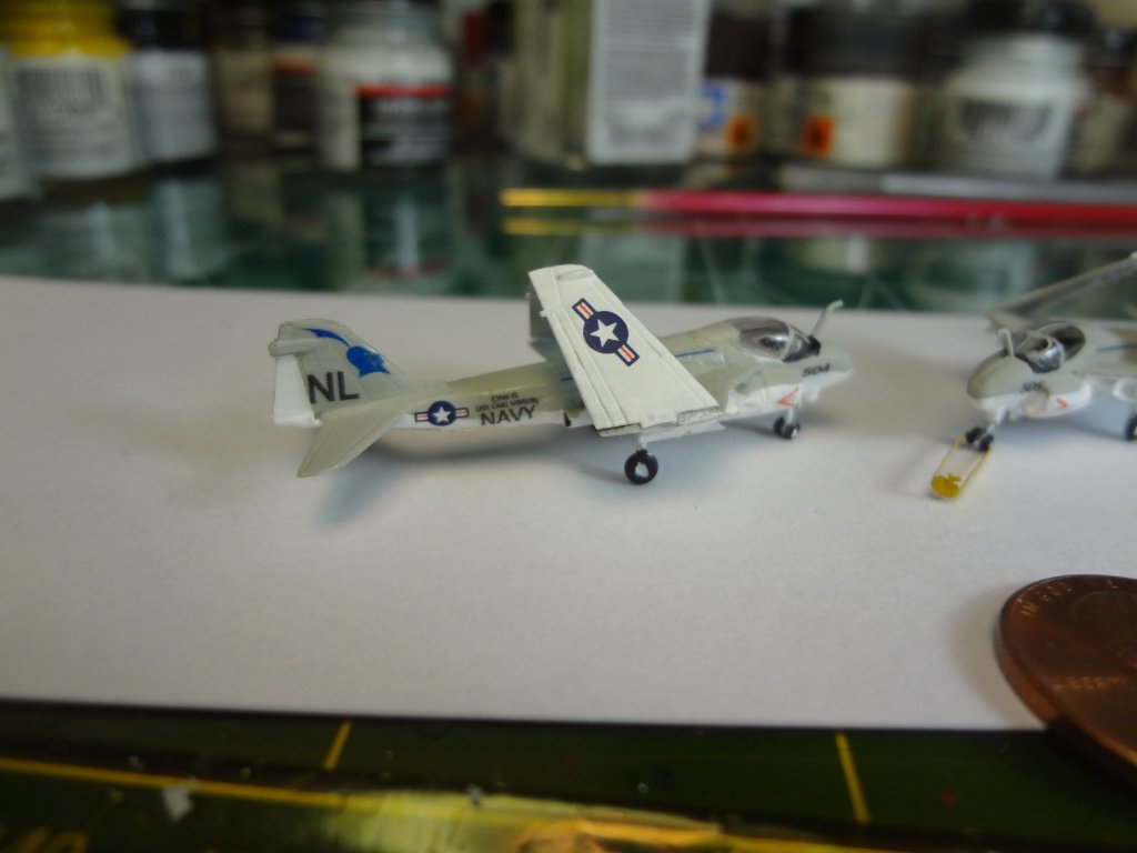
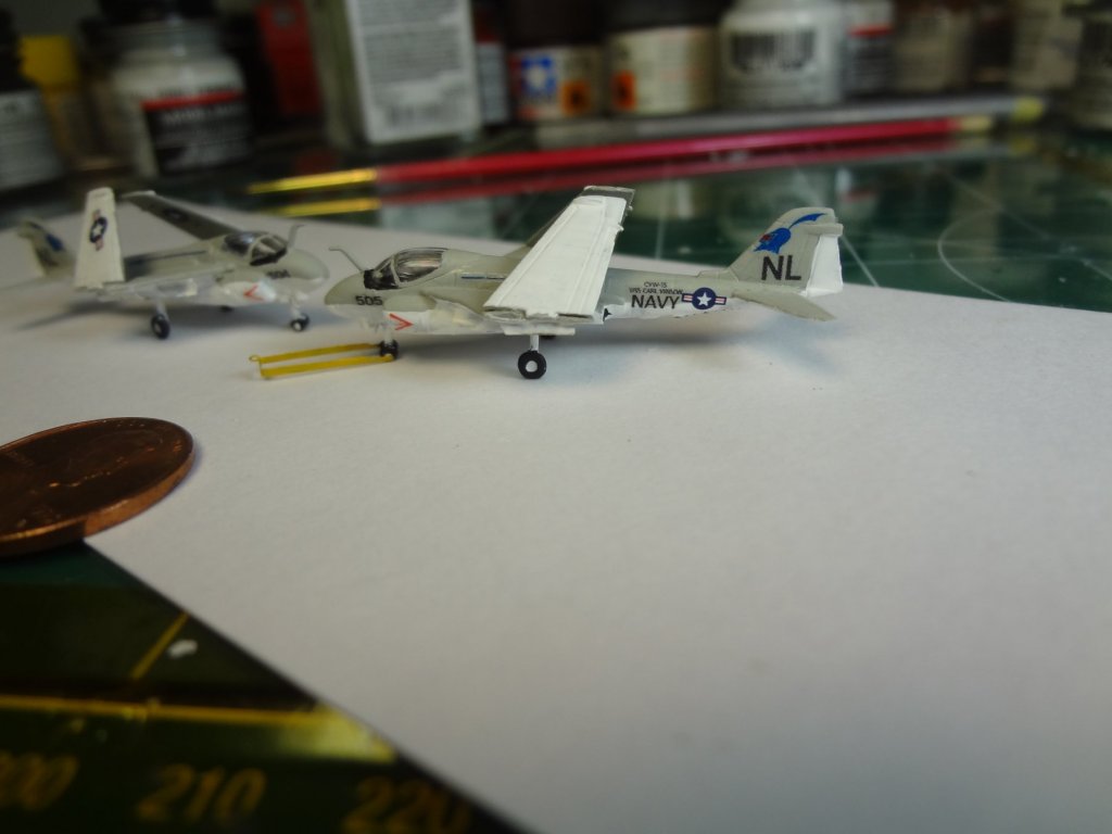
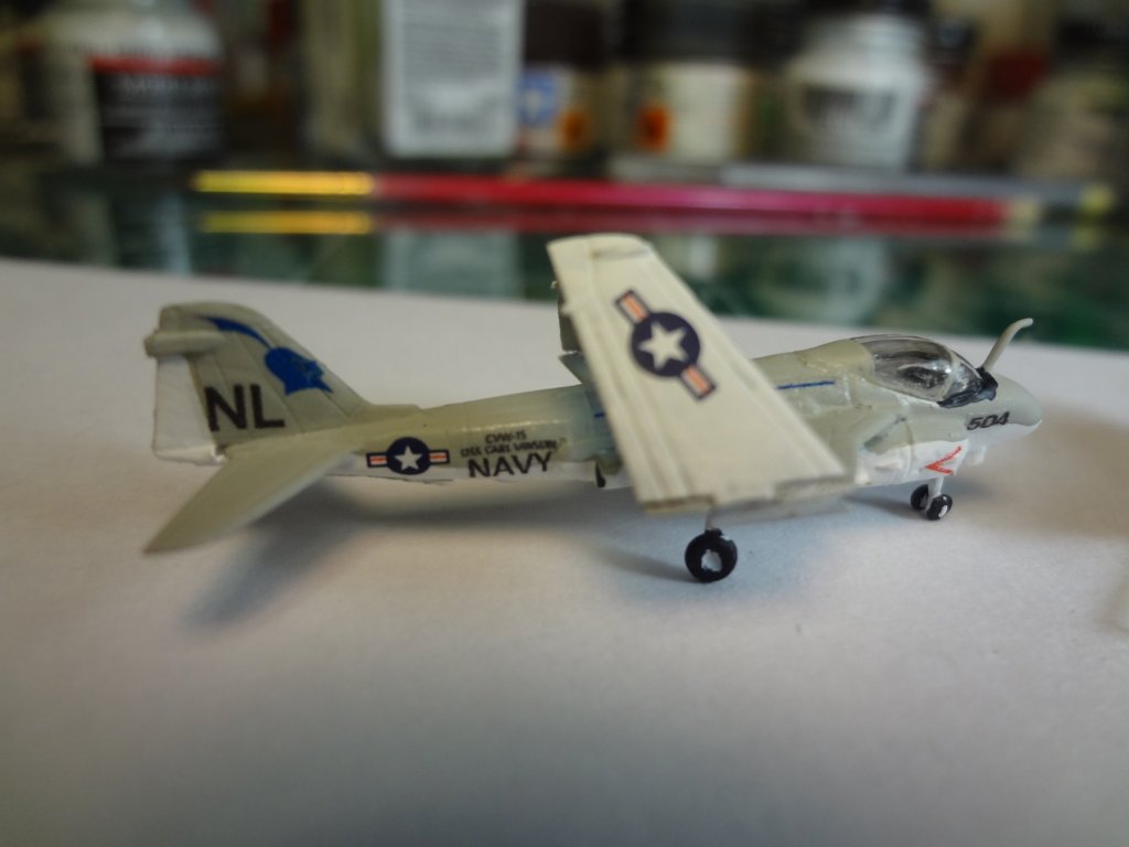
Here are the A-6E's from VA-52. The hangar bay is filling up.
- 82 replies
-
- 7
-
-
- carl vinson
- trumpeter
- (and 2 more)
-
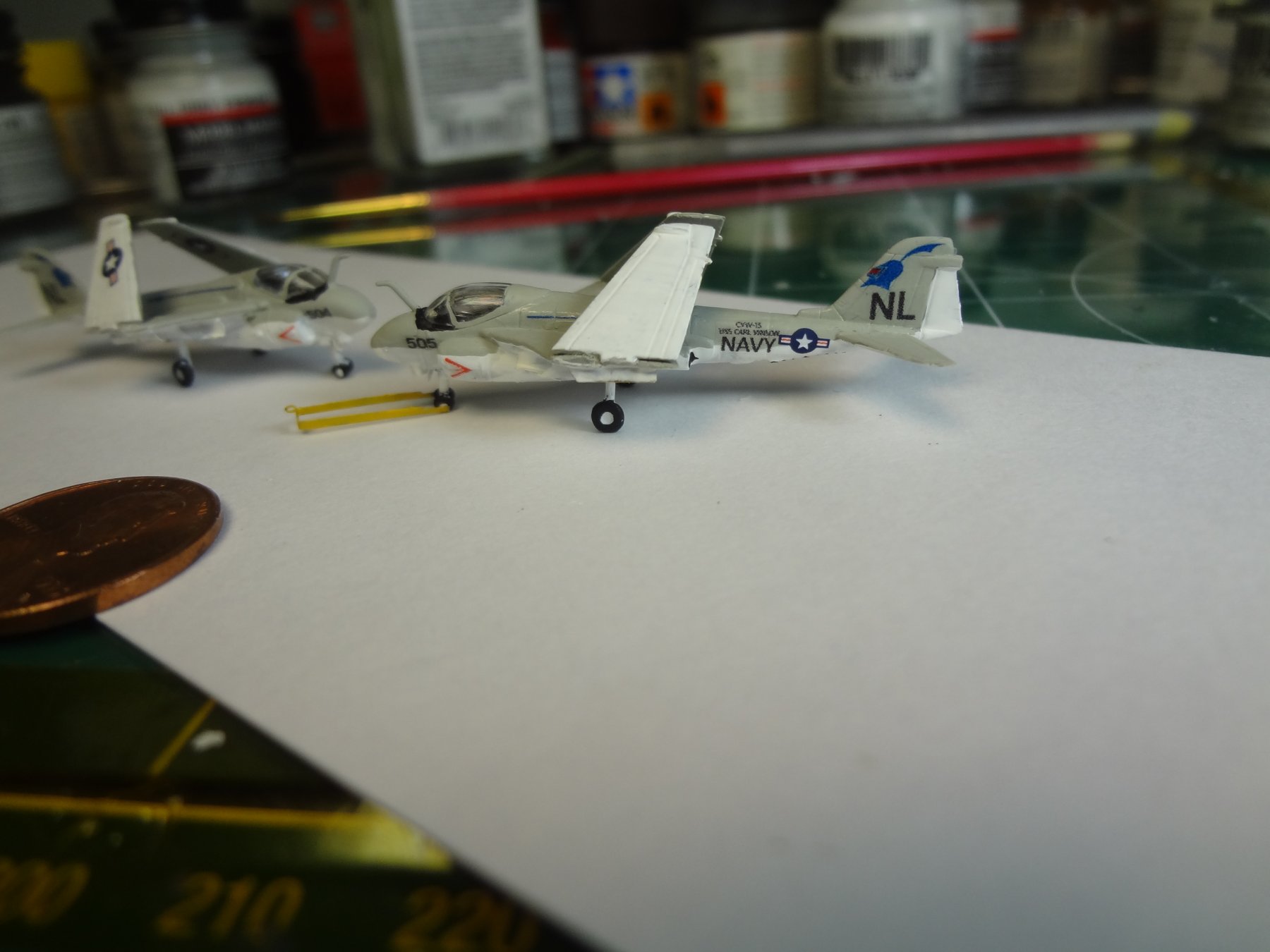
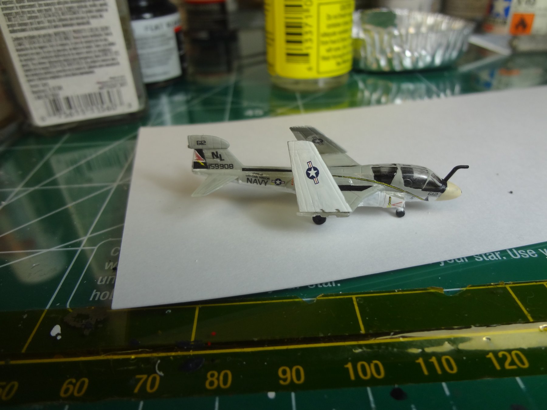
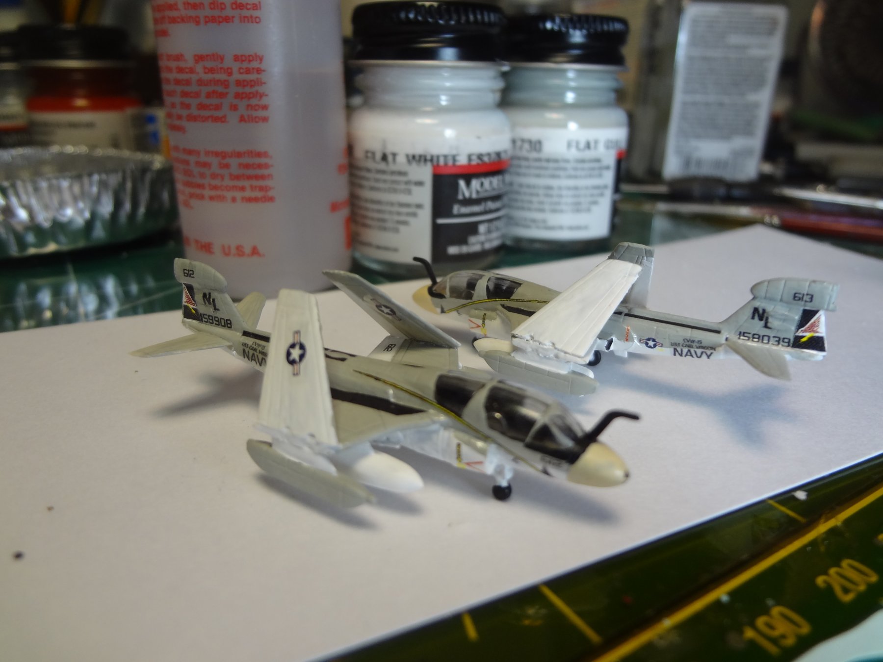
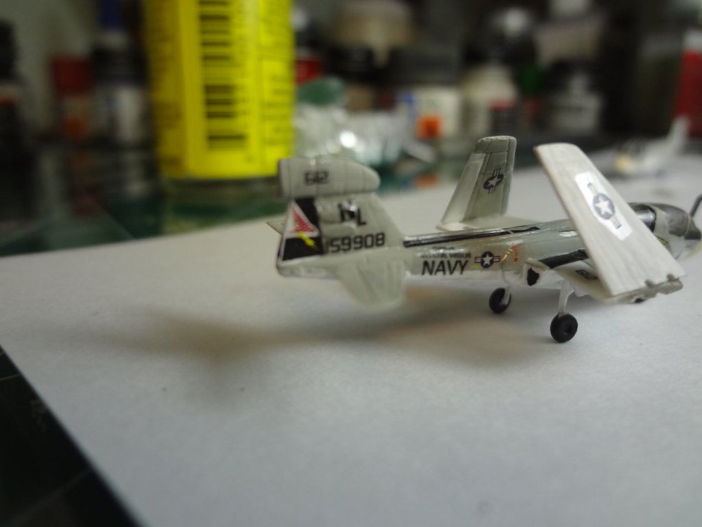
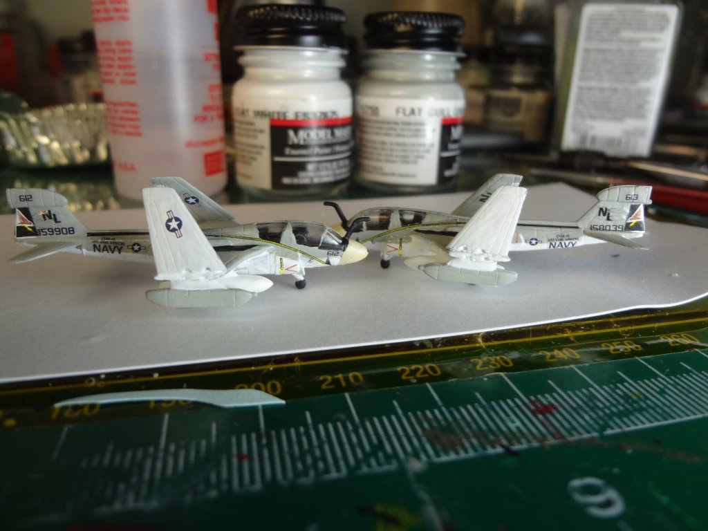
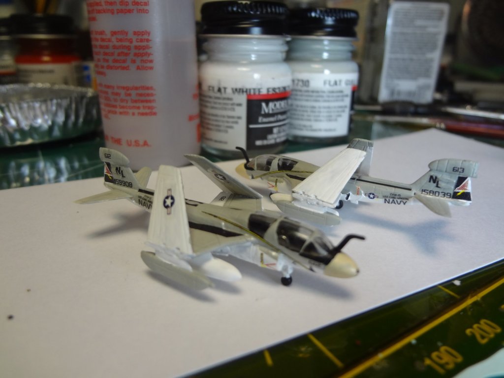
Here are the EA-6B's from VAQ-134 using Star Fighter decals.


- 82 replies
-
- 7
-
-
- carl vinson
- trumpeter
- (and 2 more)
-
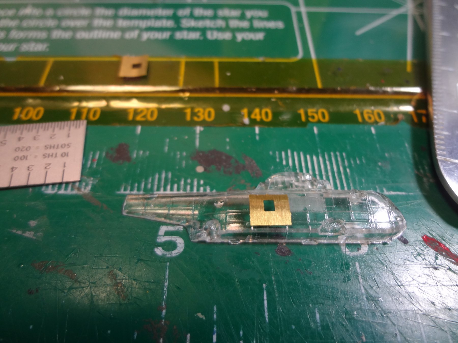
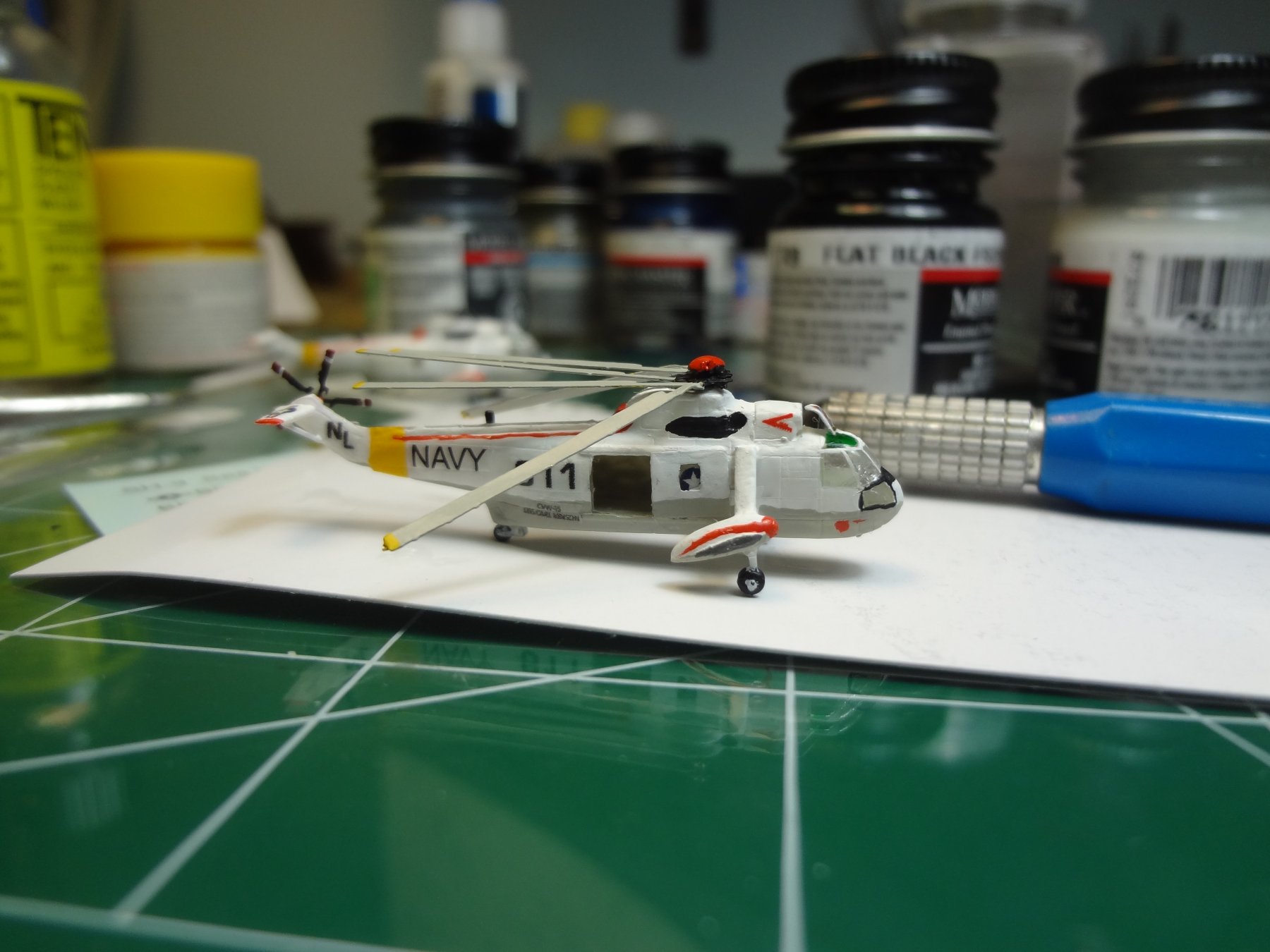
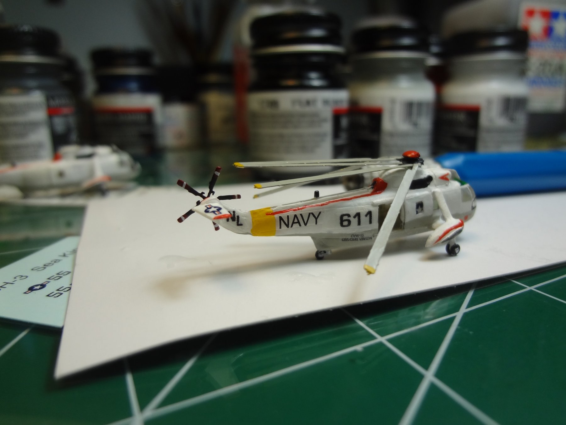
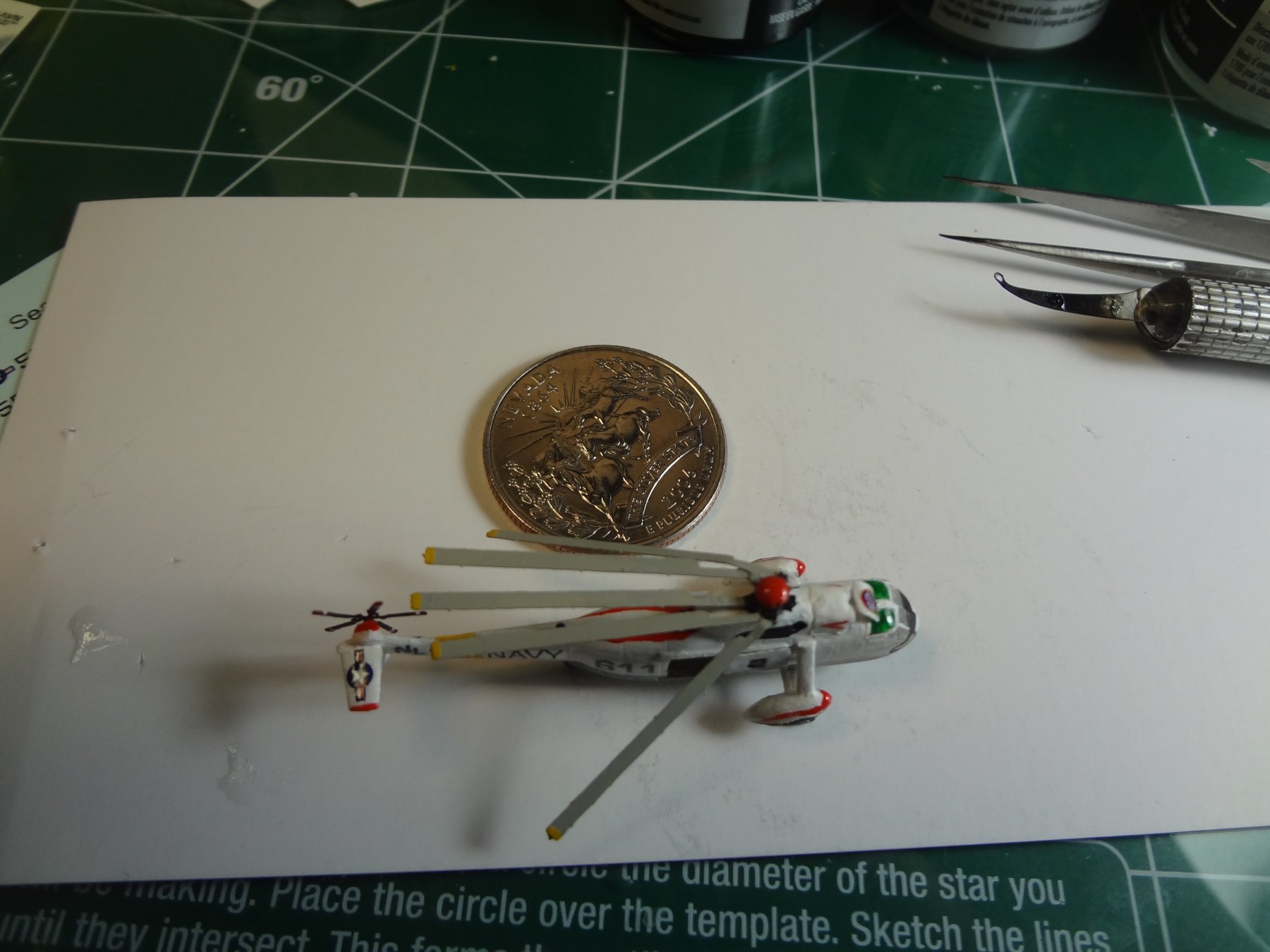
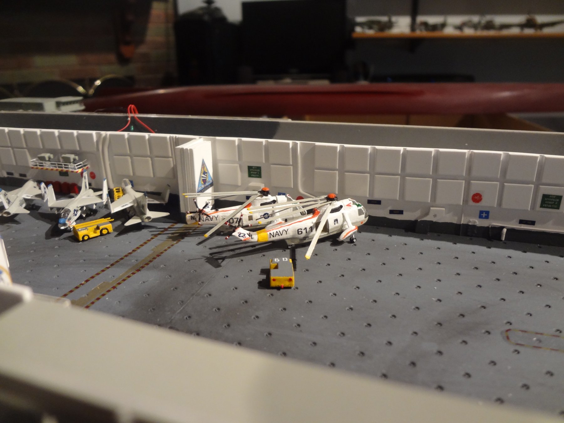
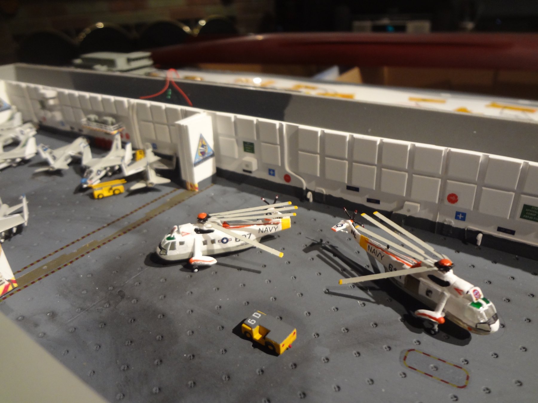
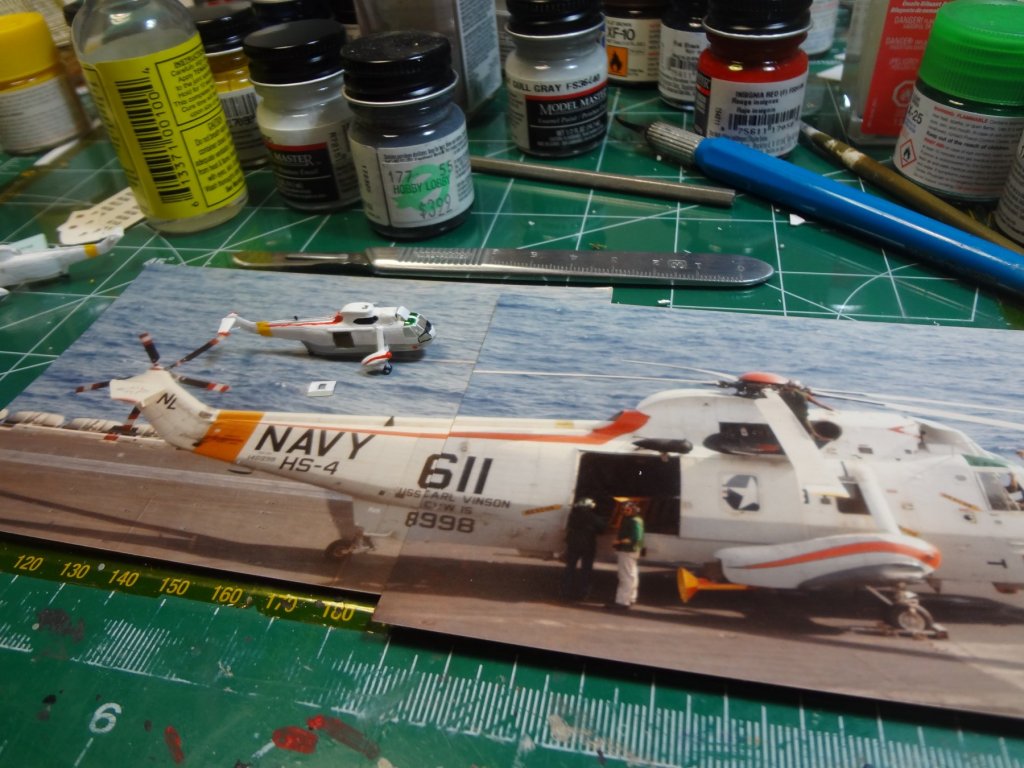
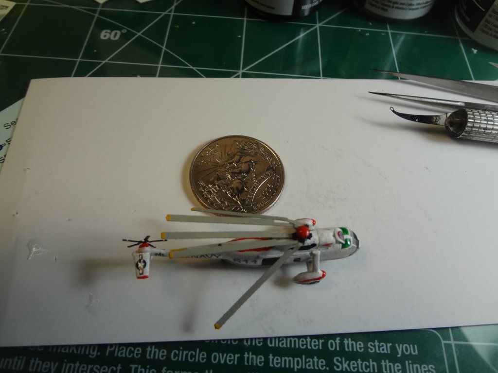
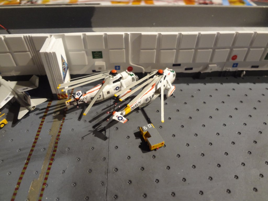
Hangar bay 1 has multiple aircraft. Starting with the SH-3's from HS-4. On one I cut open the sliding door and the other one I folded the tail. The picture of the actual helo is one I took while aboard. There was some details I needed to add like the strut from the landing gear pod to the fuselage and the intake cover.


- 82 replies
-
- 8
-
-
- carl vinson
- trumpeter
- (and 2 more)
-
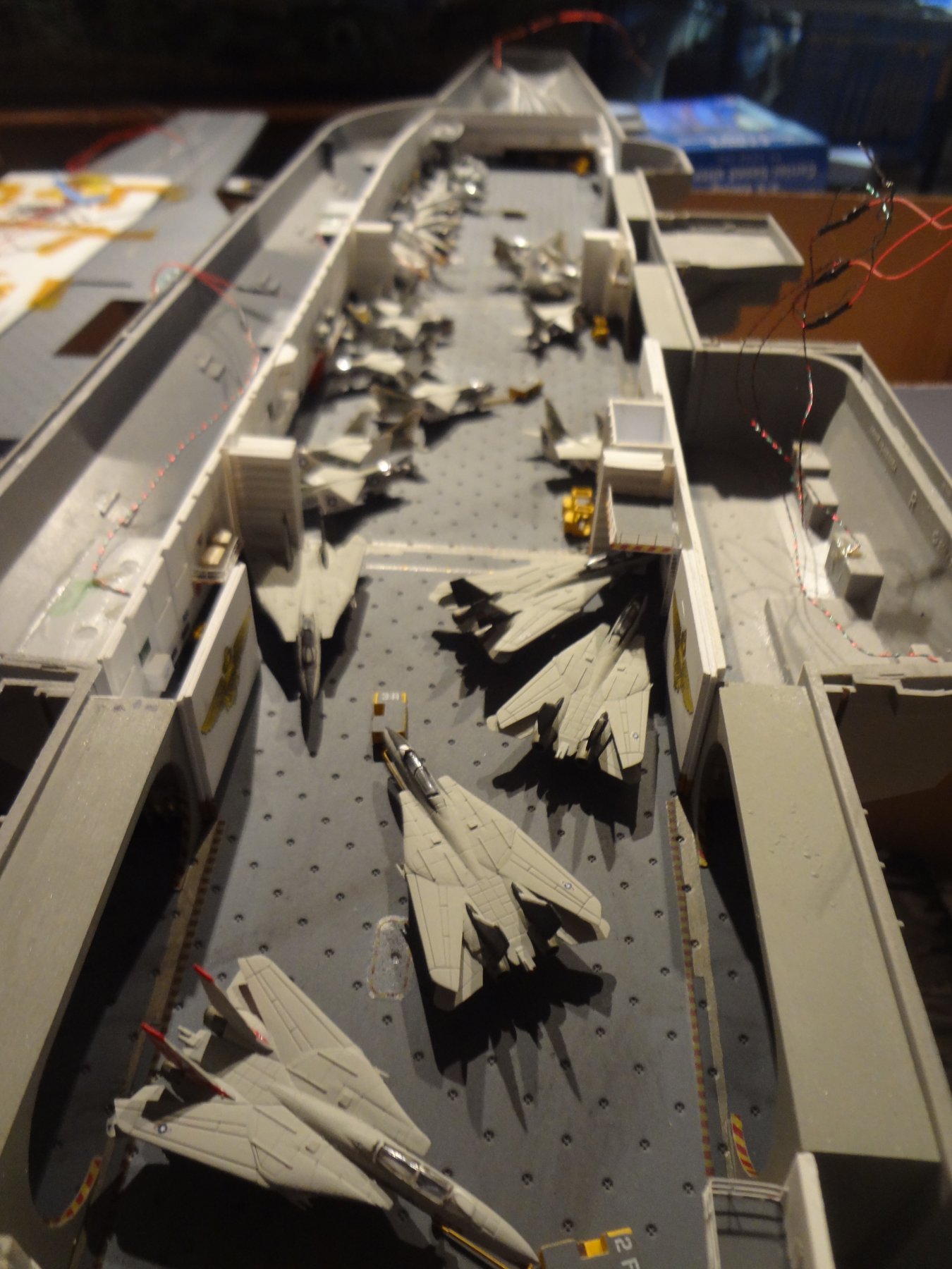
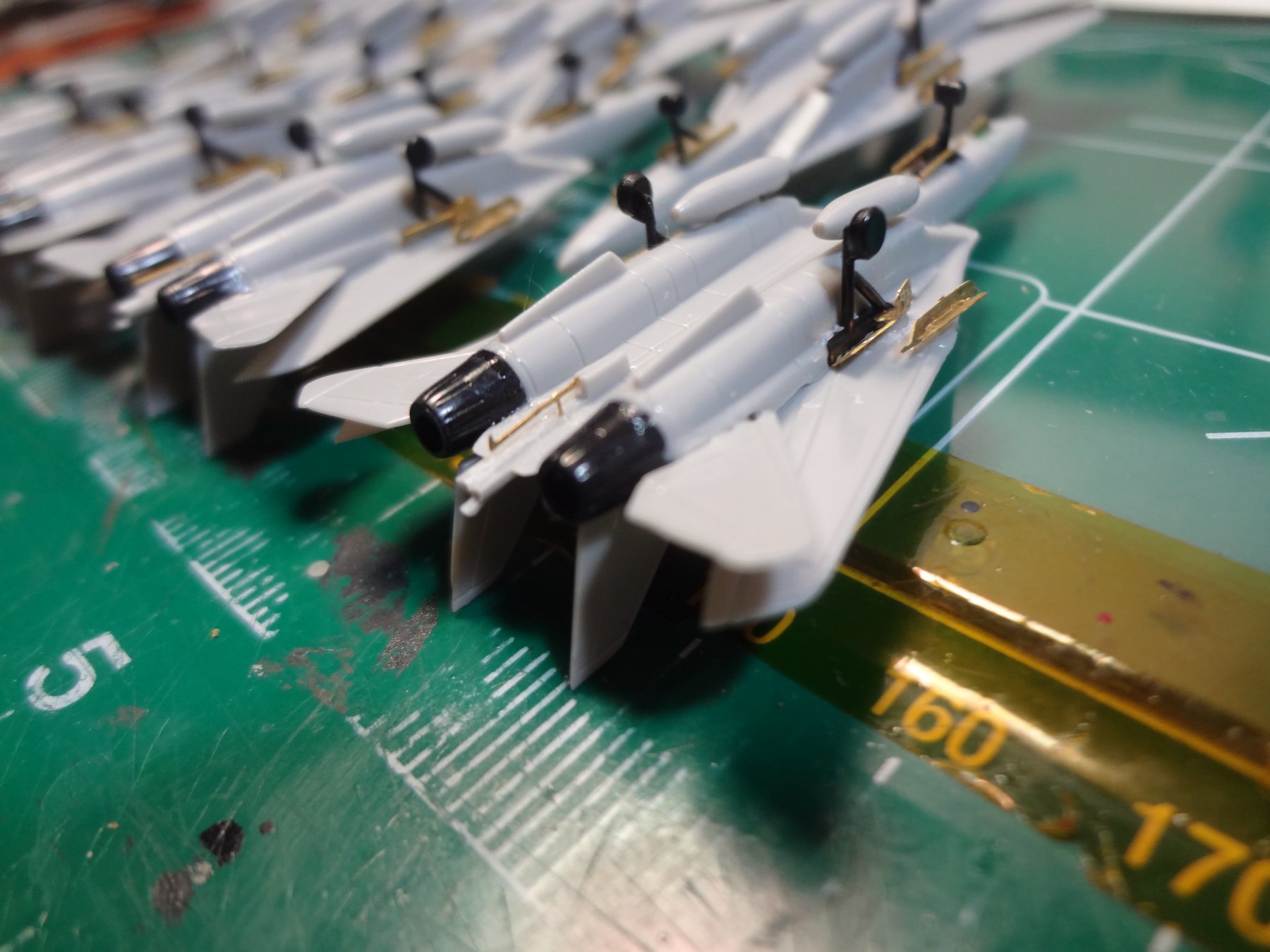
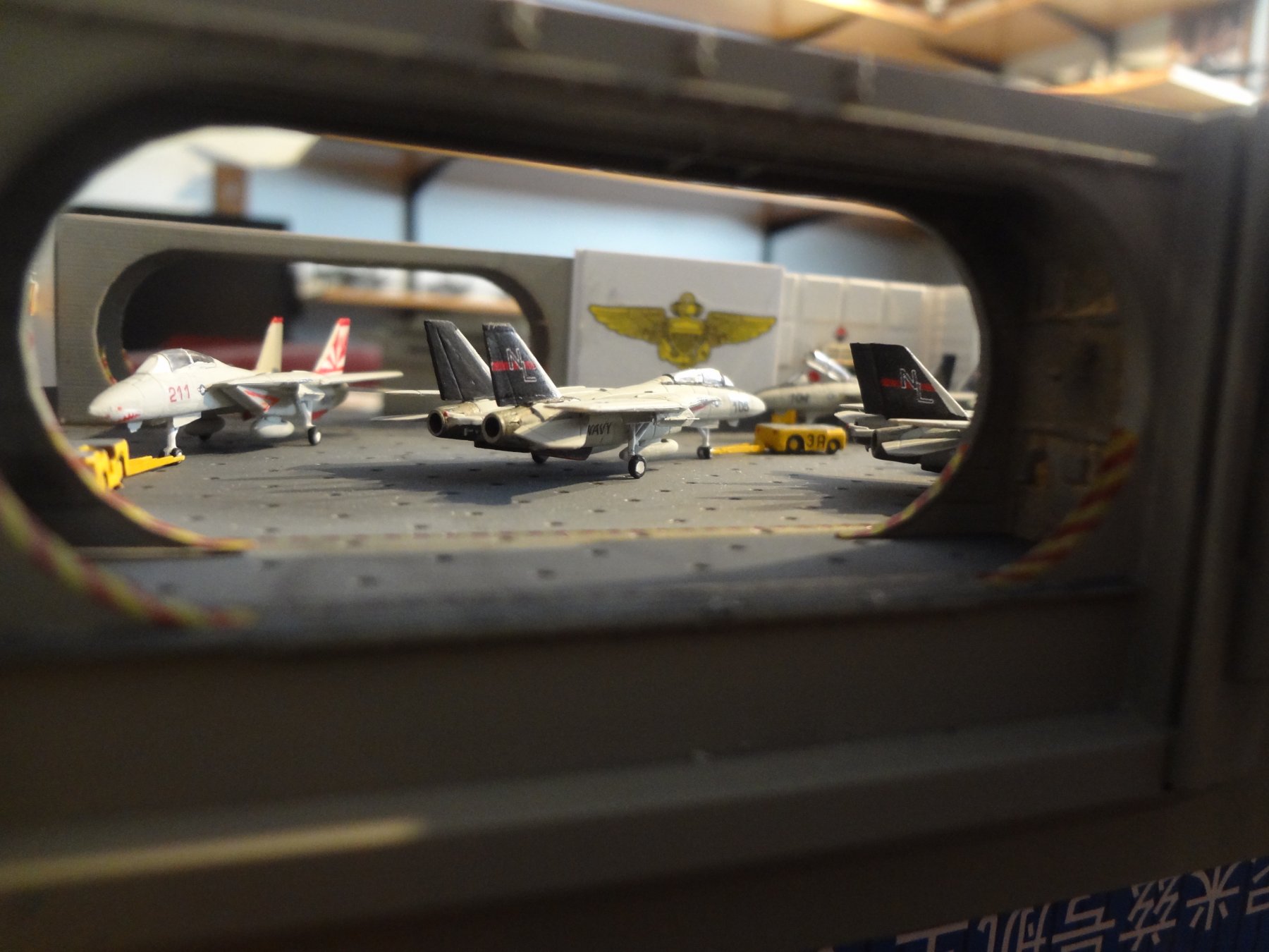
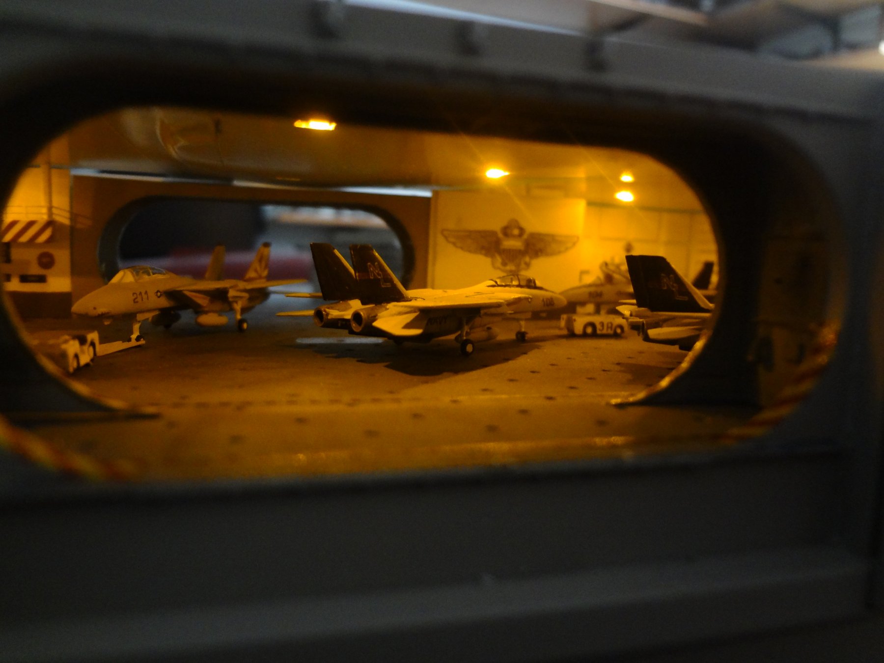
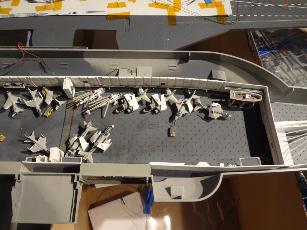
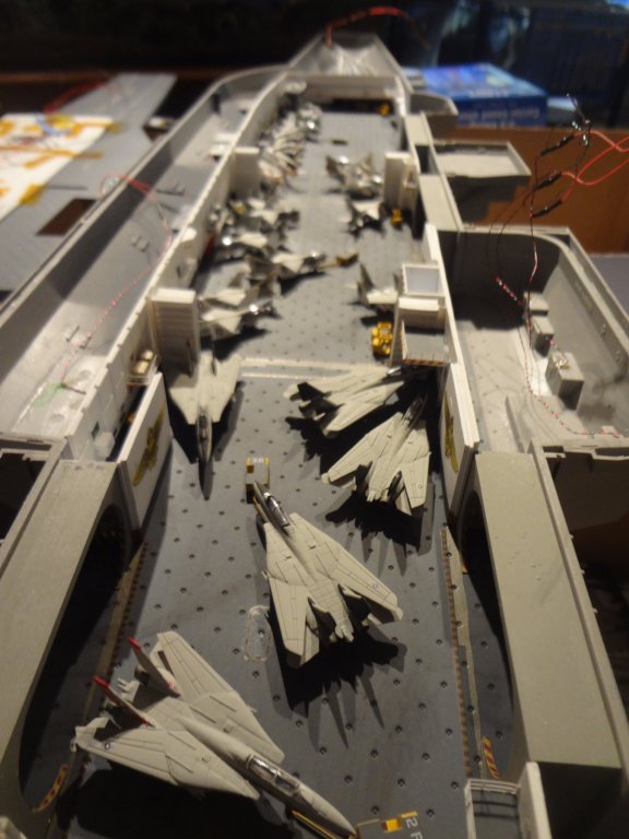
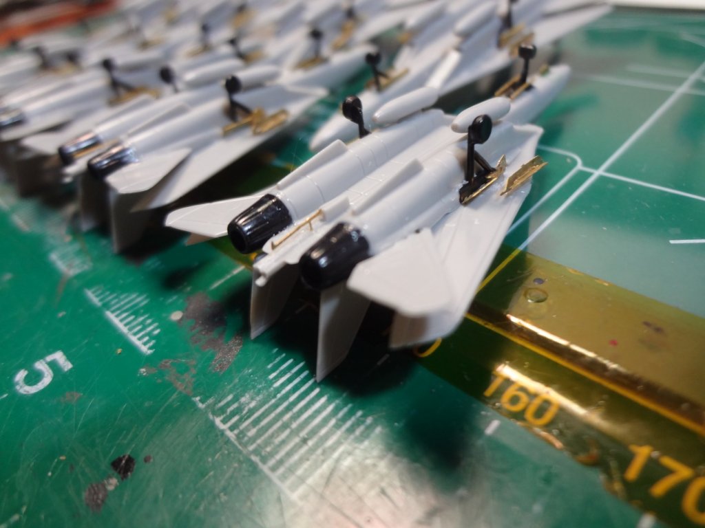
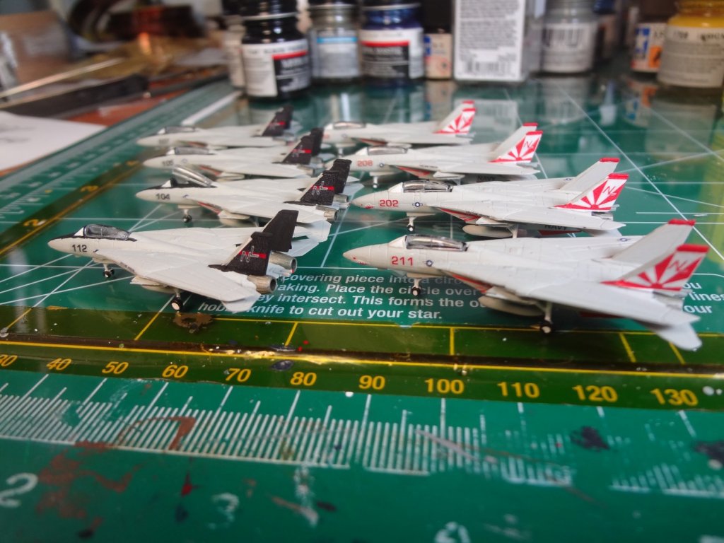
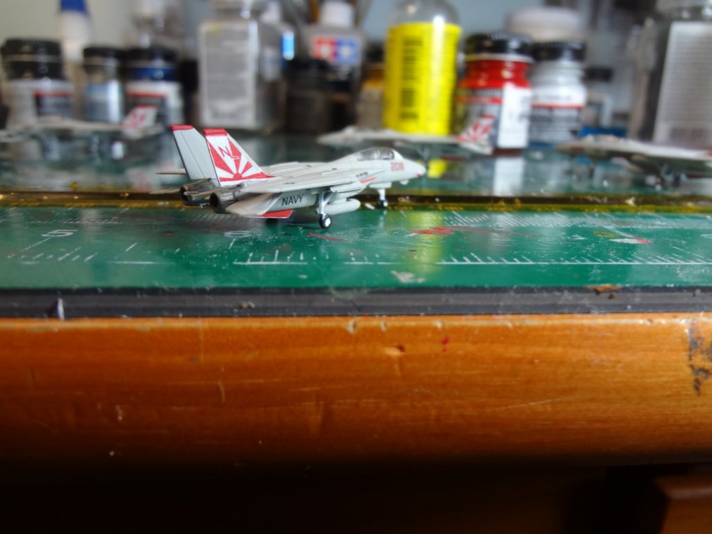
Filling hangar bay 3 with the F-14's from VF-51 and VF-111. The only disappointing part of these is that Trumpeter decided to mold the windscreens with the fuselage in gray plastic. Do not understand why this was done. All the other Trumpeter aircraft have clear canopies.


- 82 replies
-
- 8
-
-
- carl vinson
- trumpeter
- (and 2 more)
-
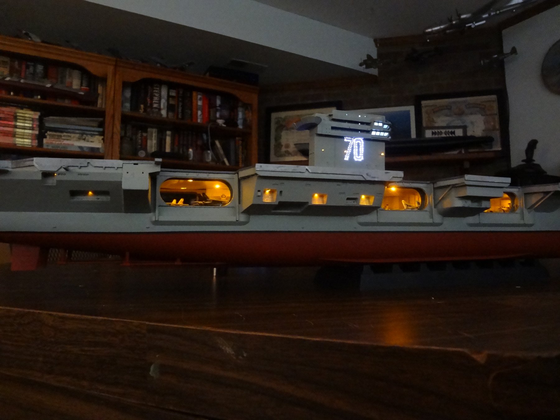
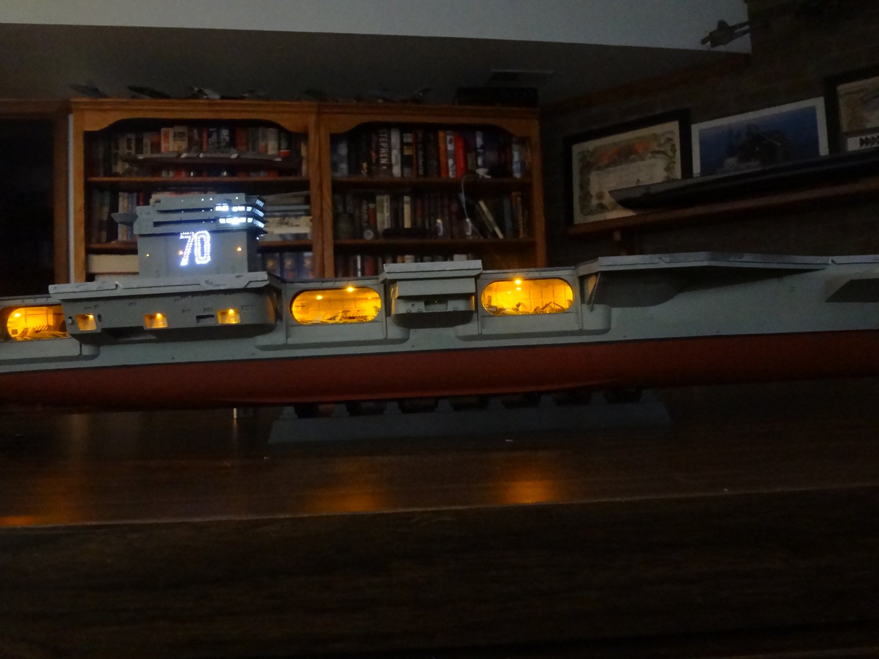
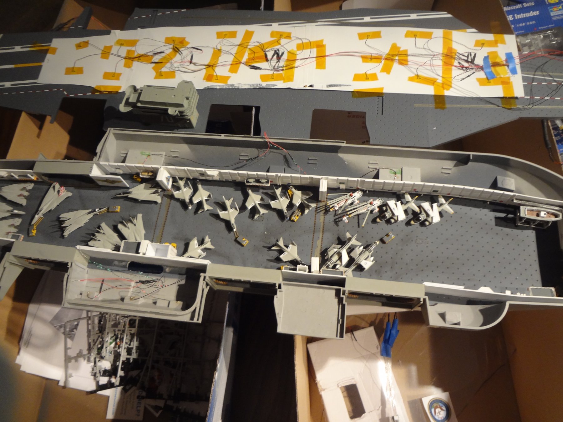
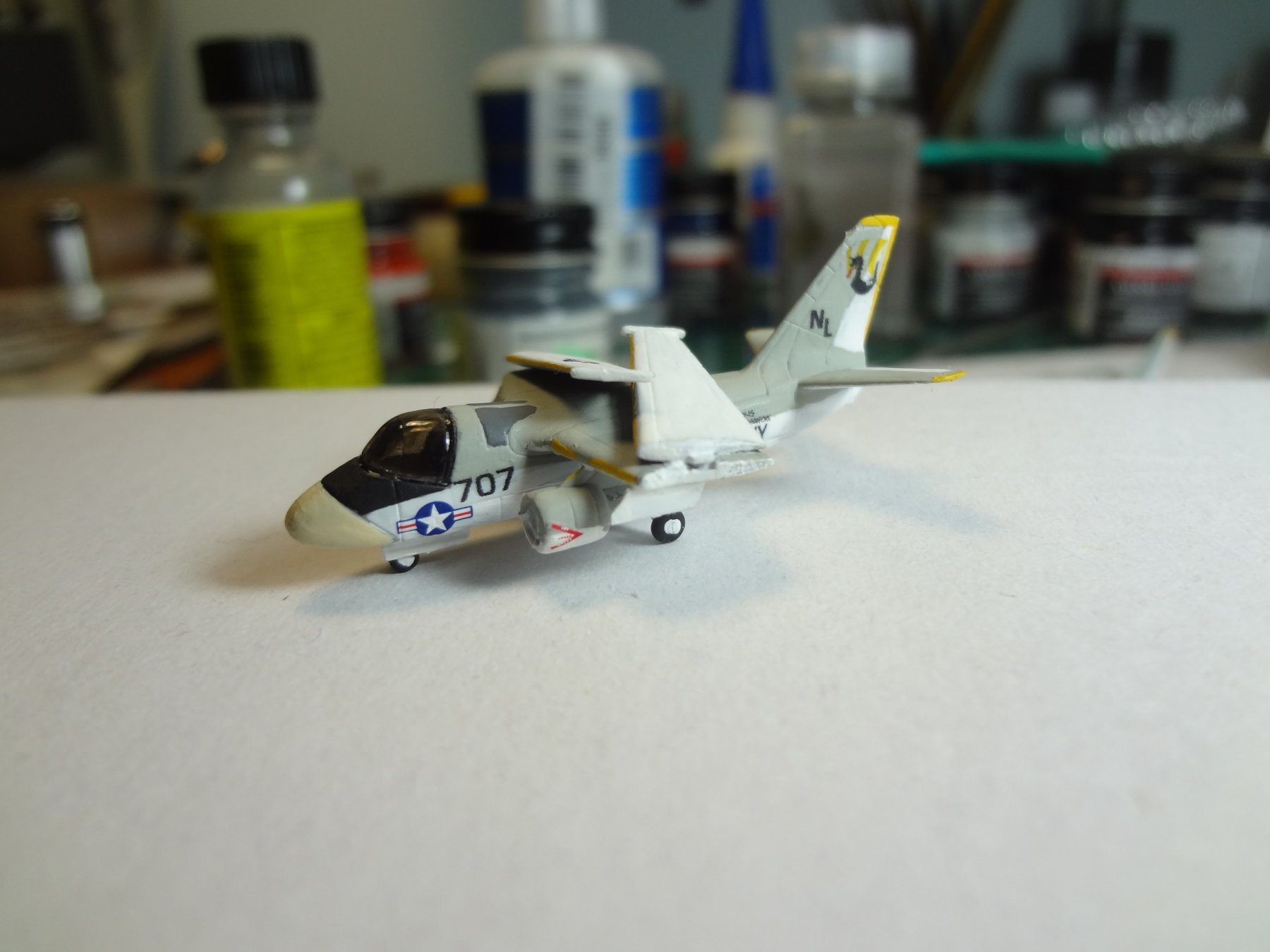
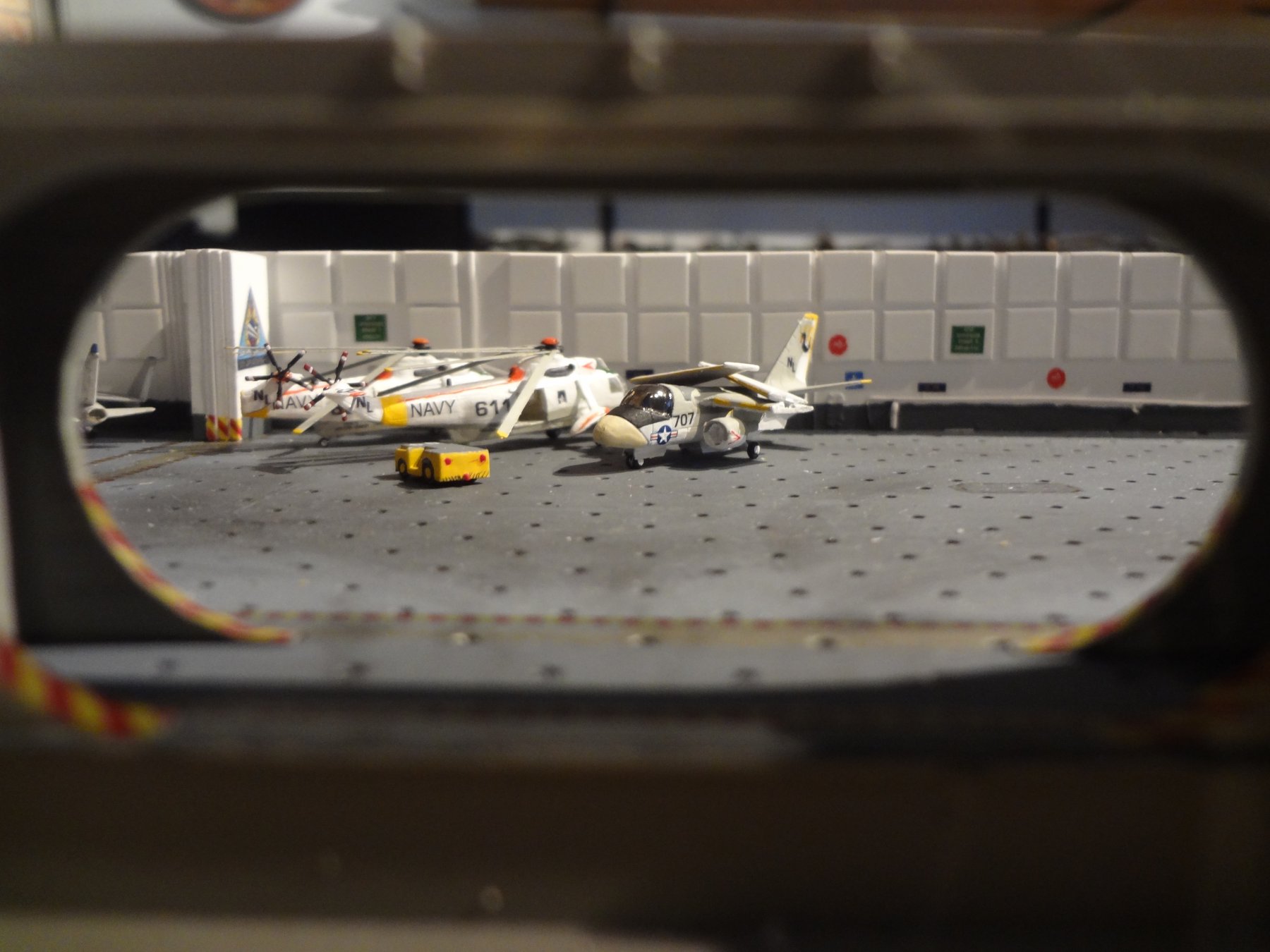
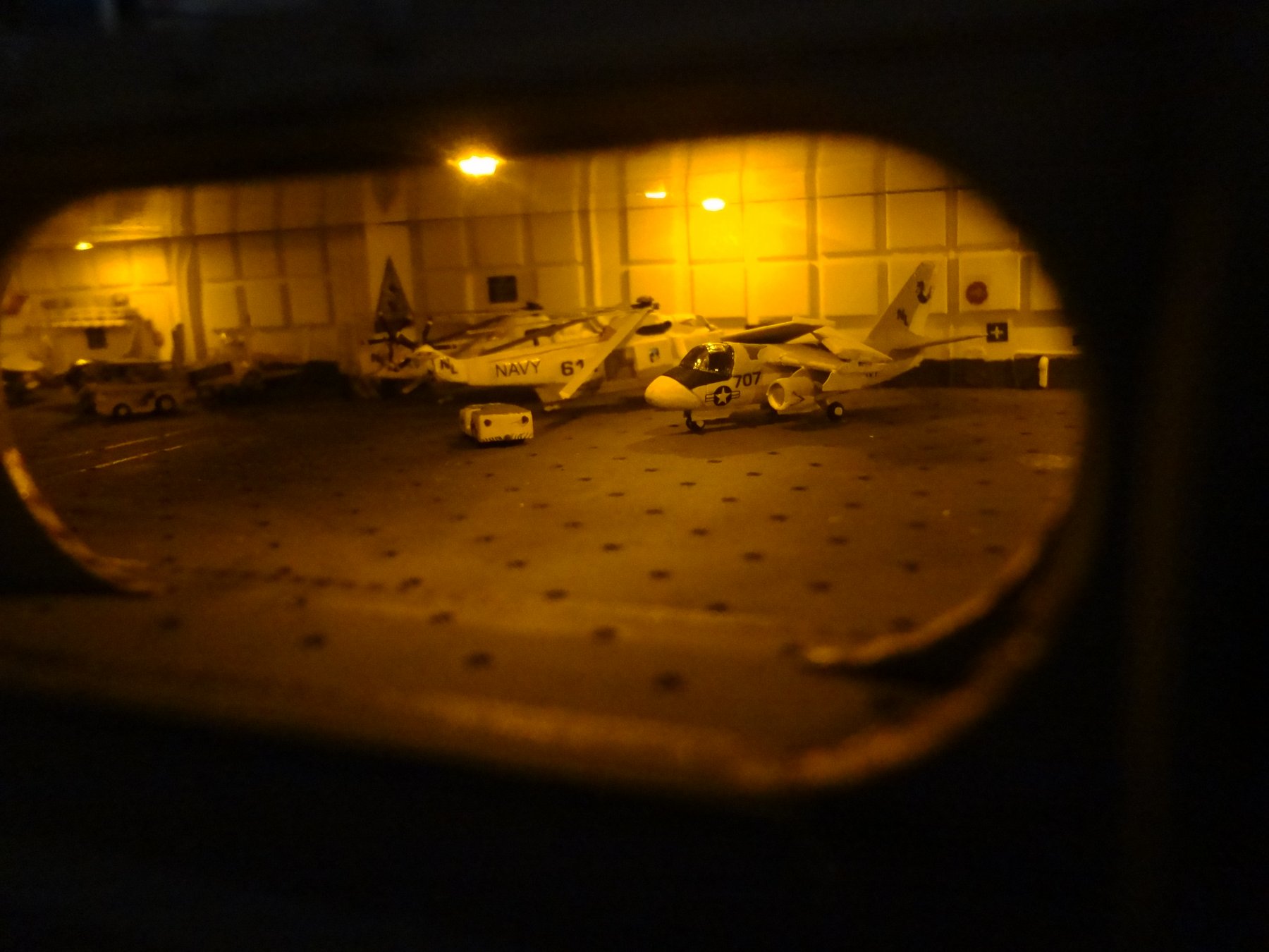
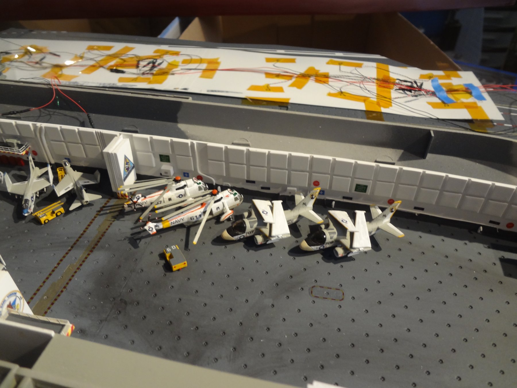
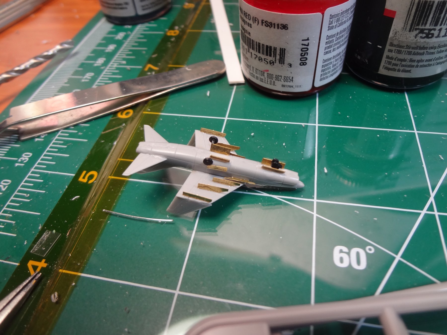
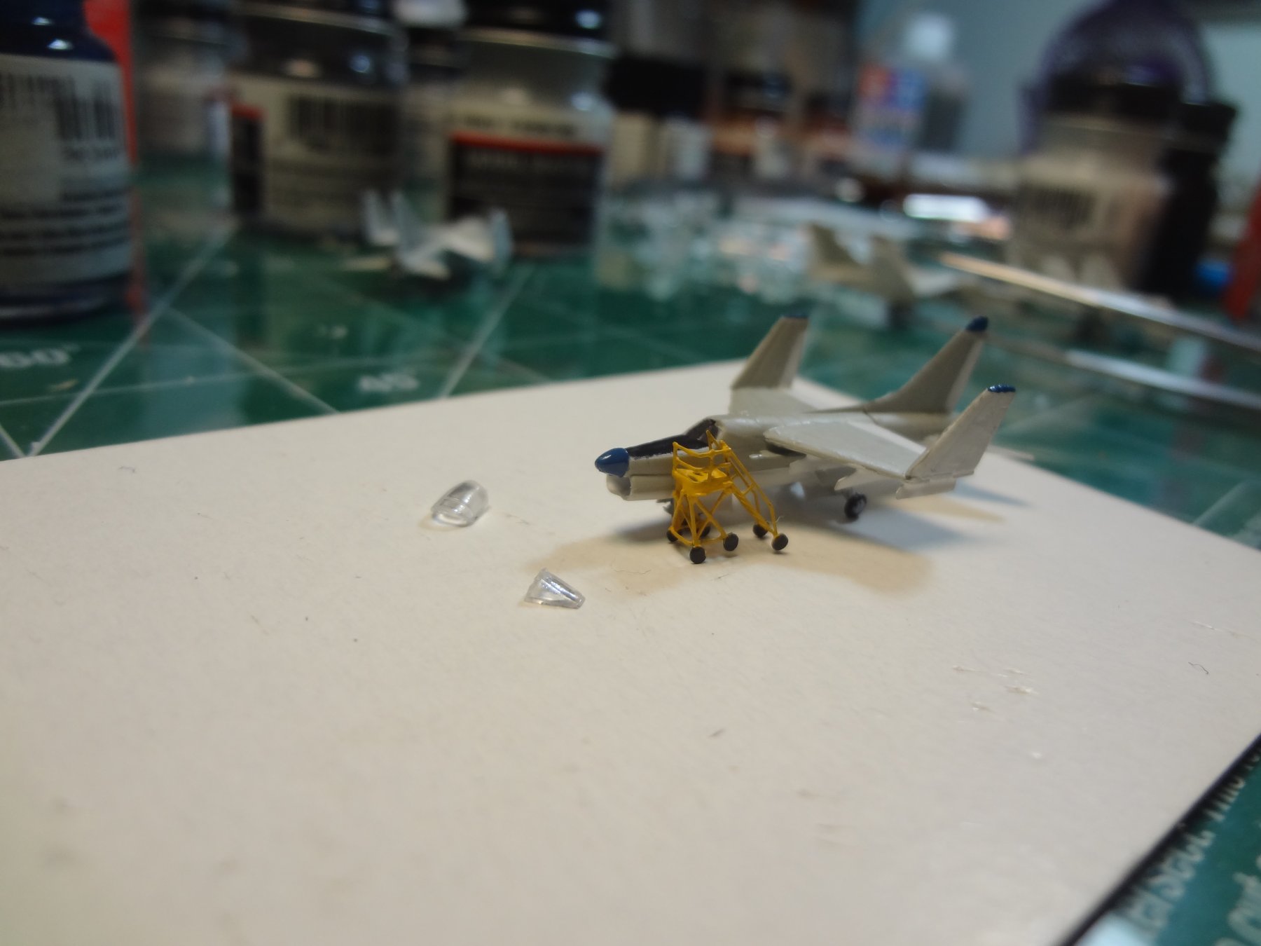
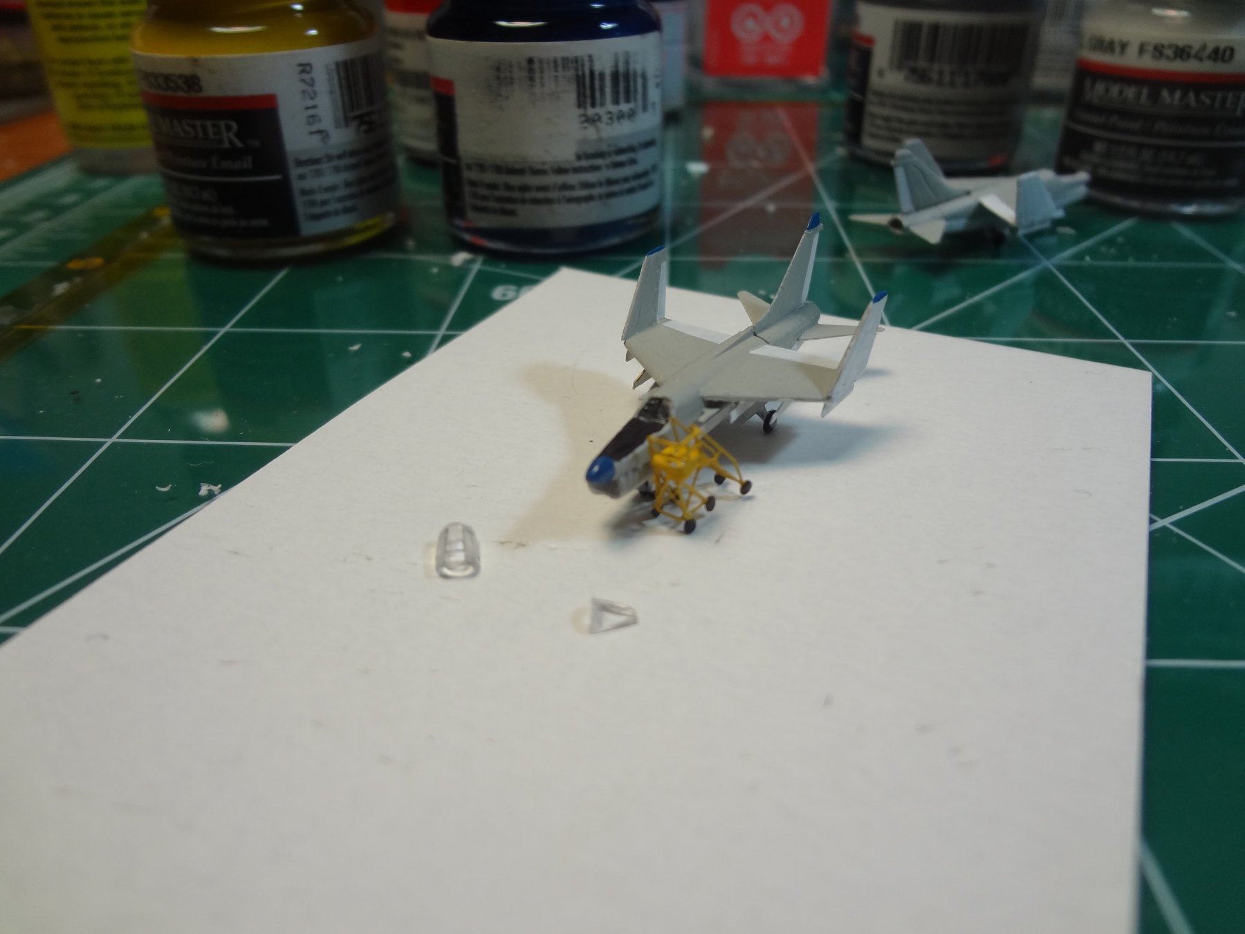
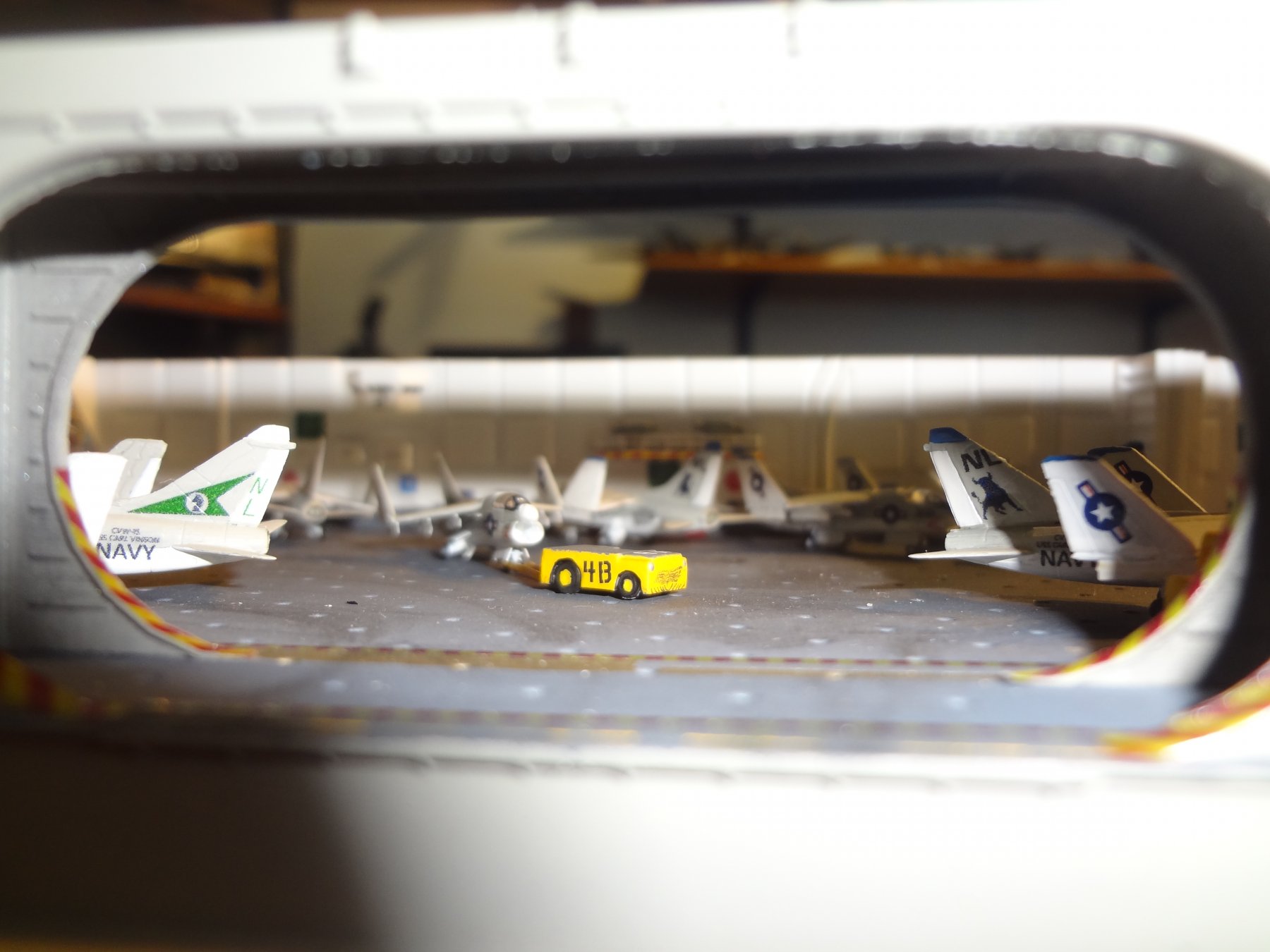
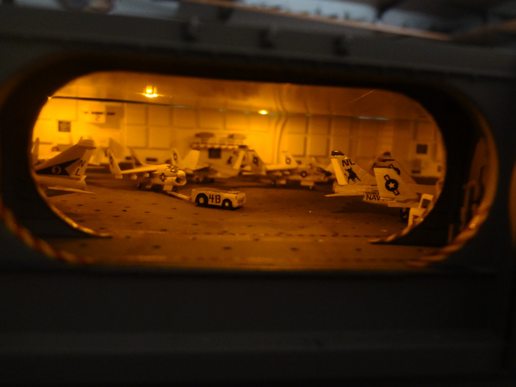
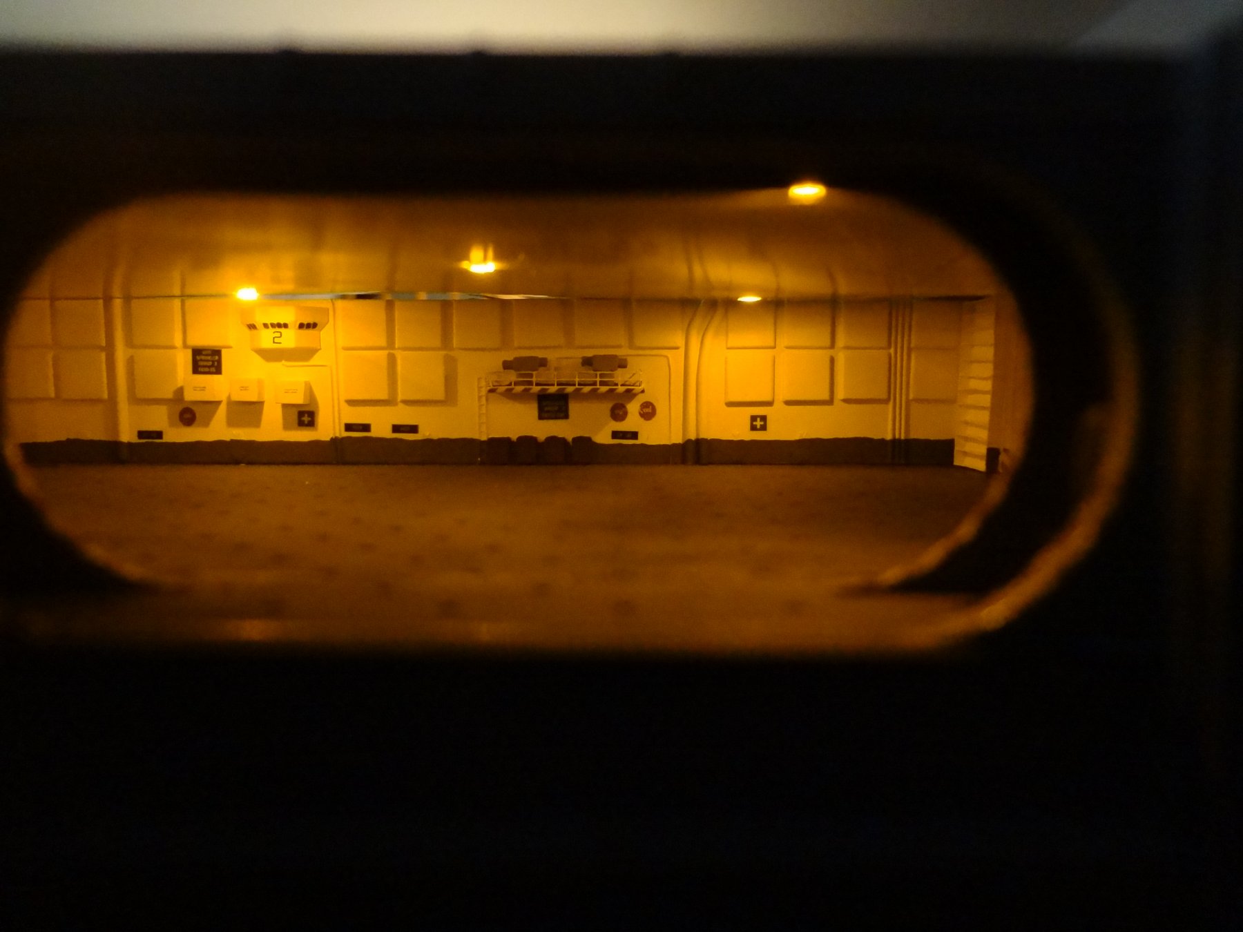
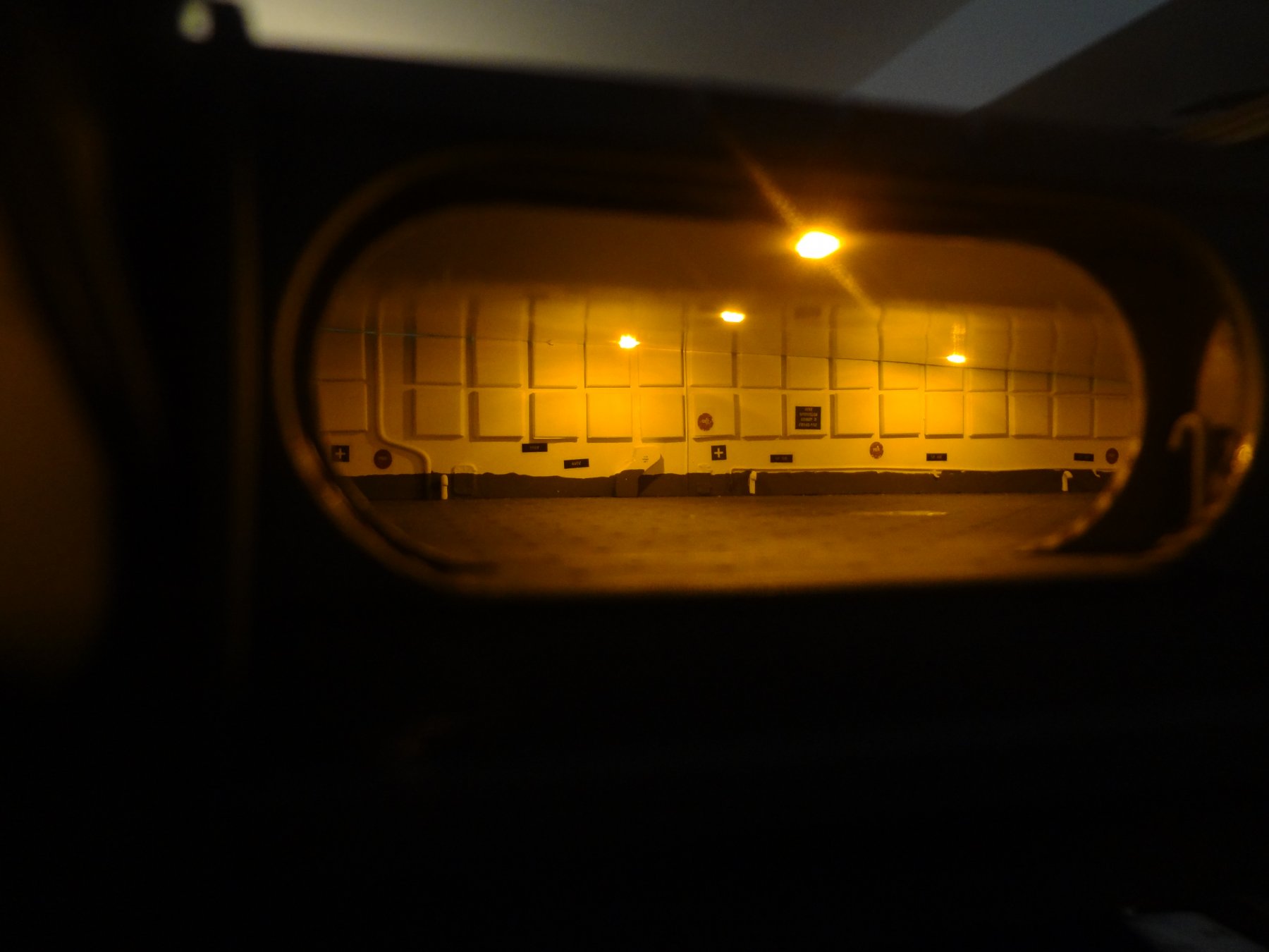
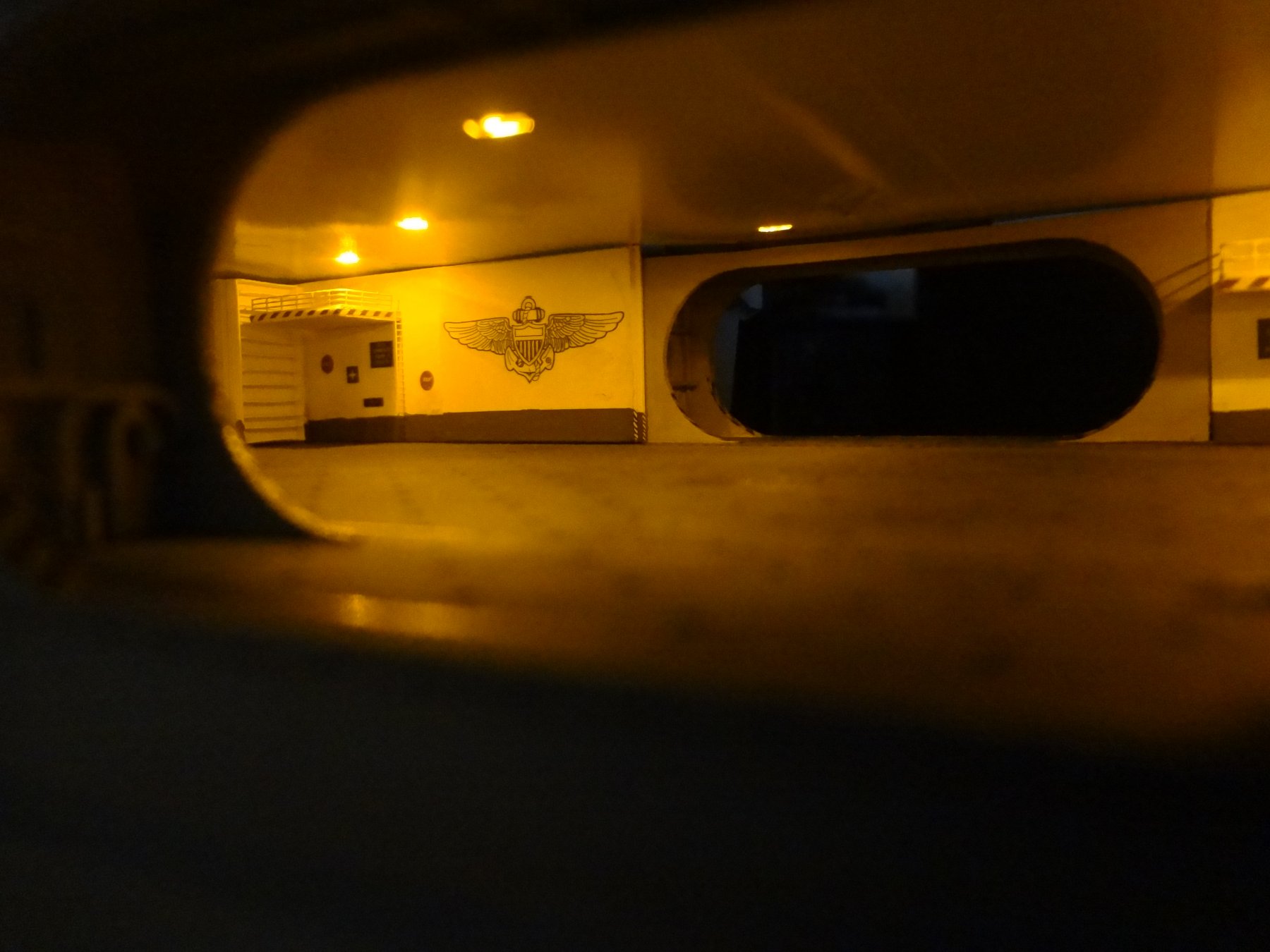
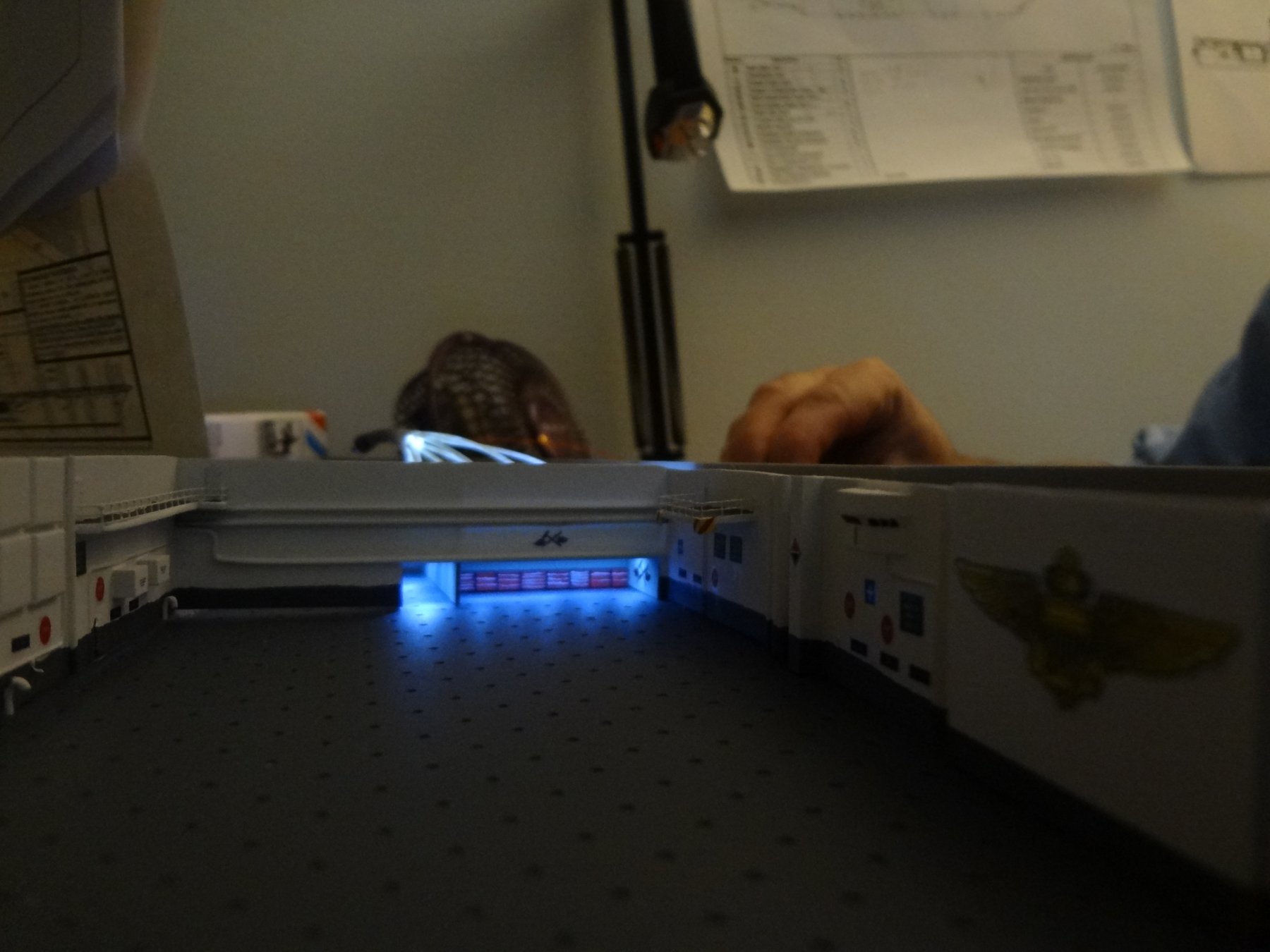
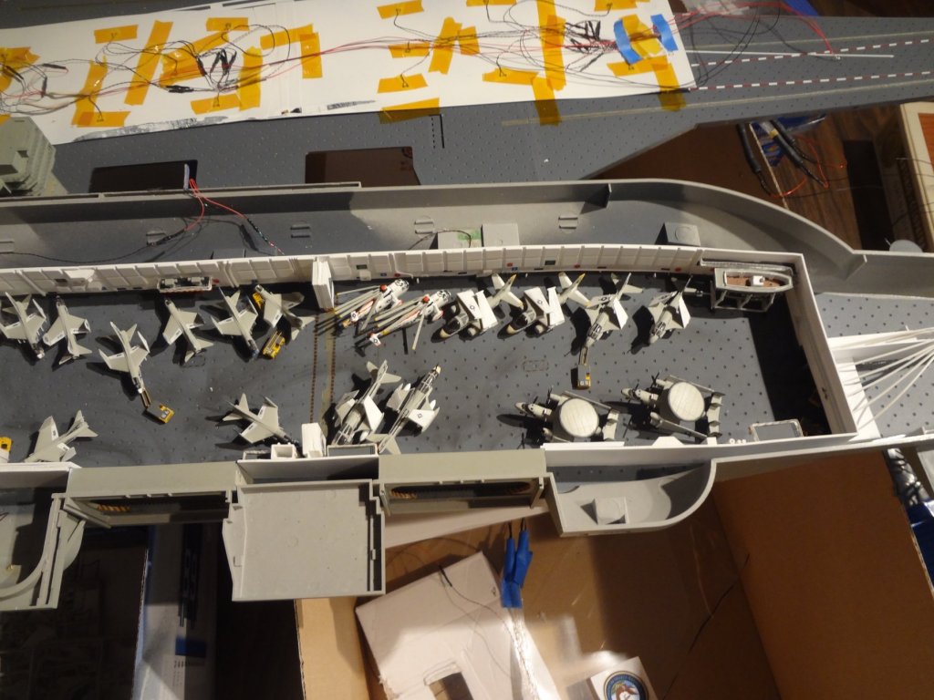
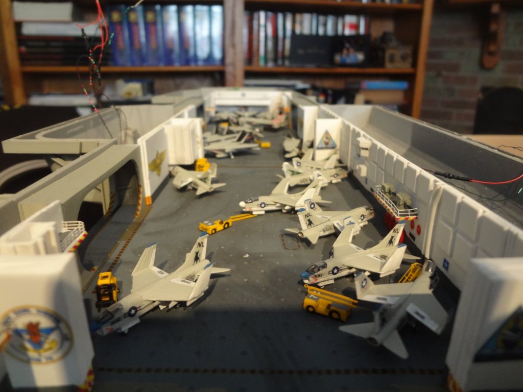
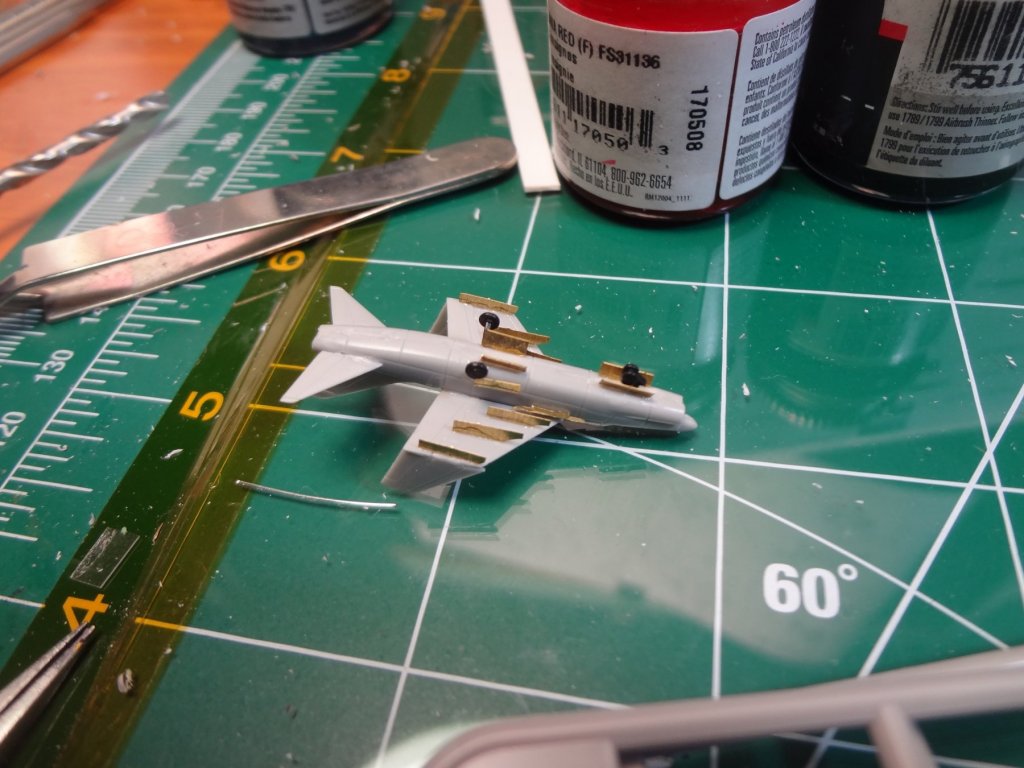
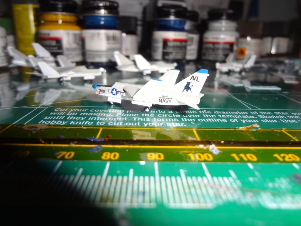
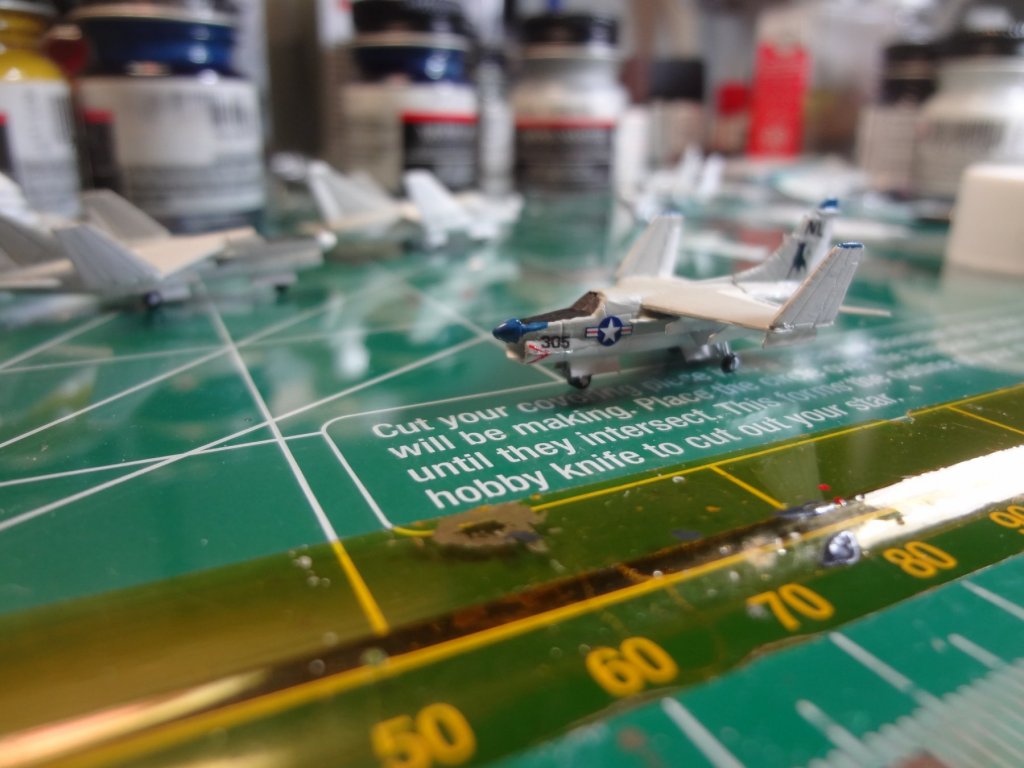
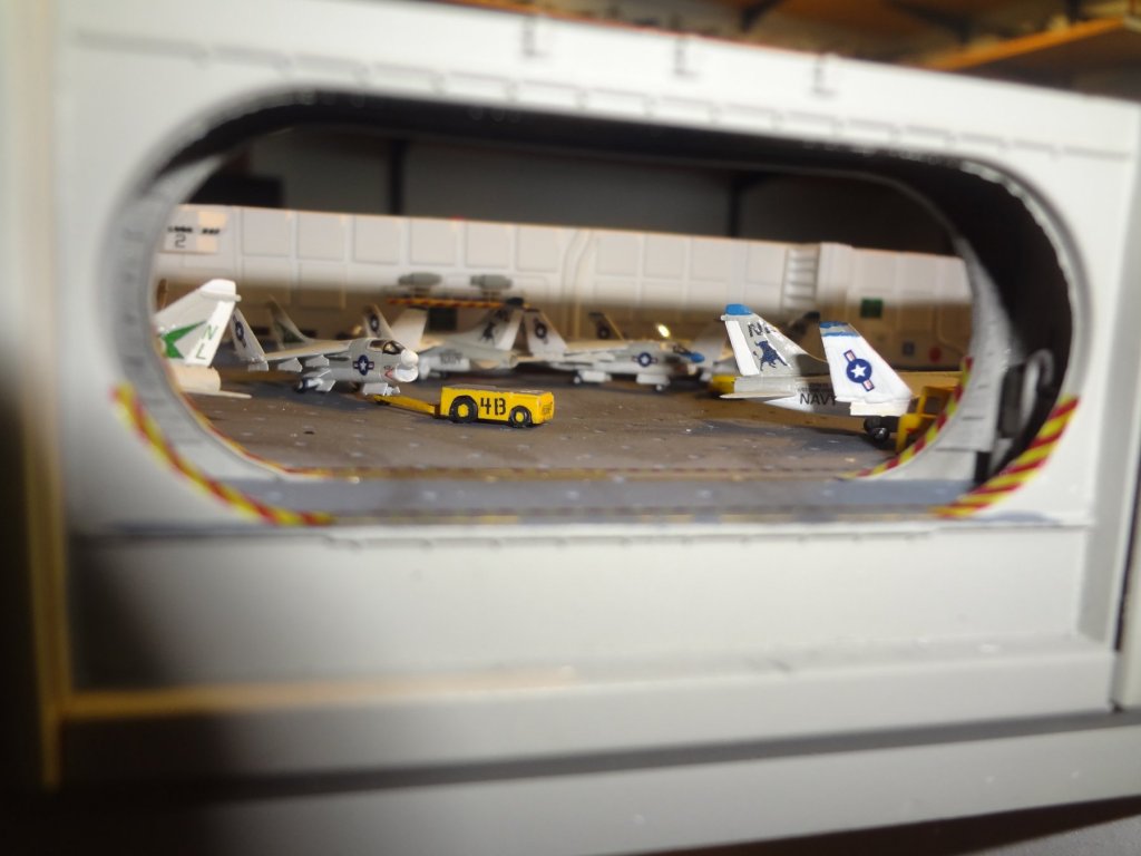
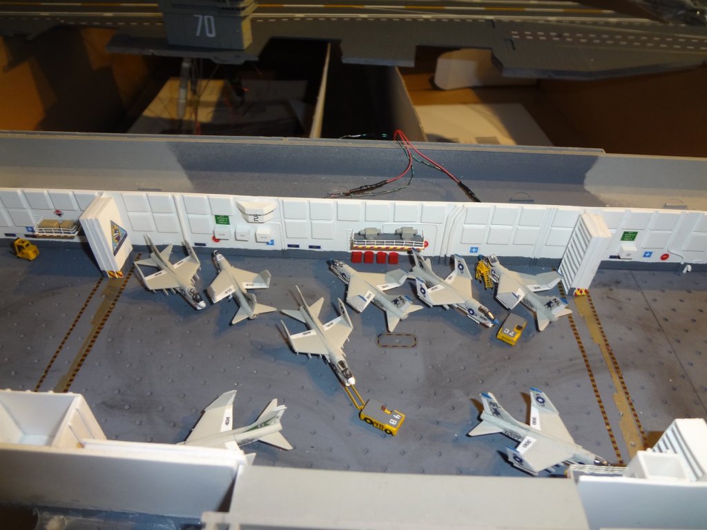
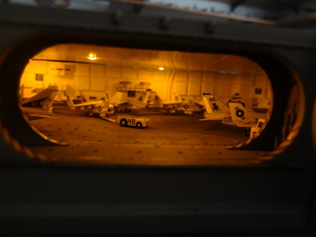
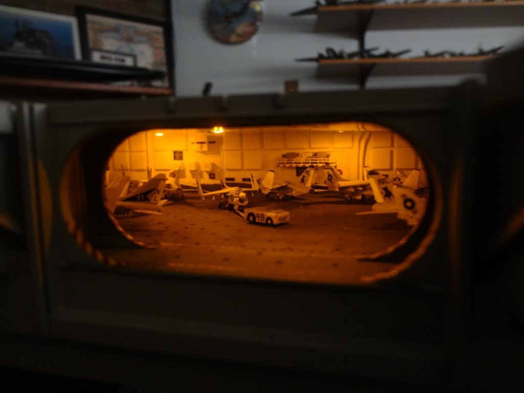
At this point I realized due to the routing and wiring the flight deck and island needed to be put on the hull together. This required the hangar bay to be filled and detailed first. I started with hangar bay 2 which was home to the A-7 aircraft of VA-37 and VA-105. I scratch built a cockpit maintenance platform and cut one canopy to show the canopy raised. Tom's Modelworks photoetch details were added to all aircraft. All the decals were made by me except for the EA-6B's. Star Fighter decals were available for these and the deck tractors. Anyone who has been on a US Navy aircraft carrier at night will remember working in the yellow glow of the hangar bays.


- 82 replies
-
- 12
-
-
- carl vinson
- trumpeter
- (and 2 more)
-
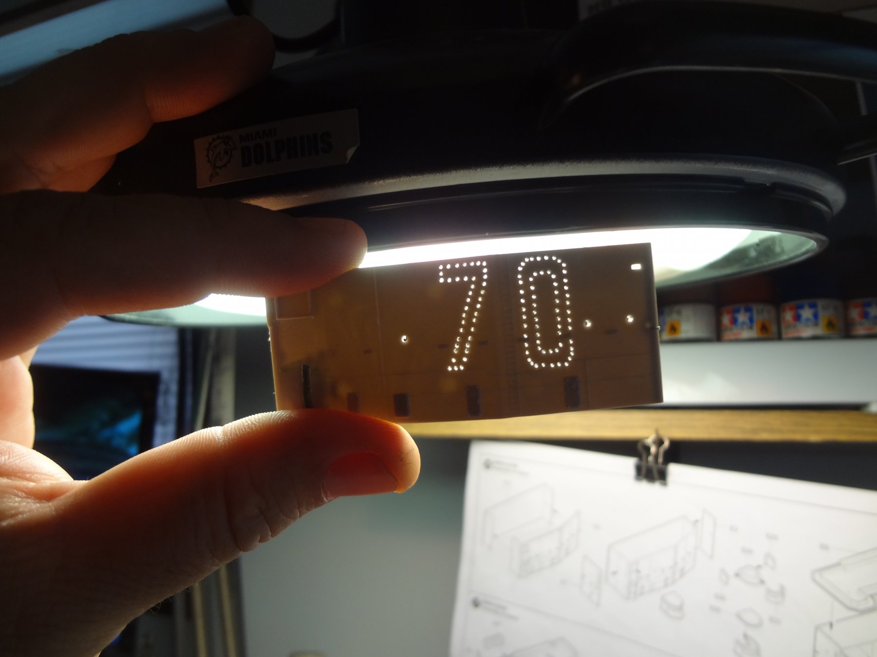
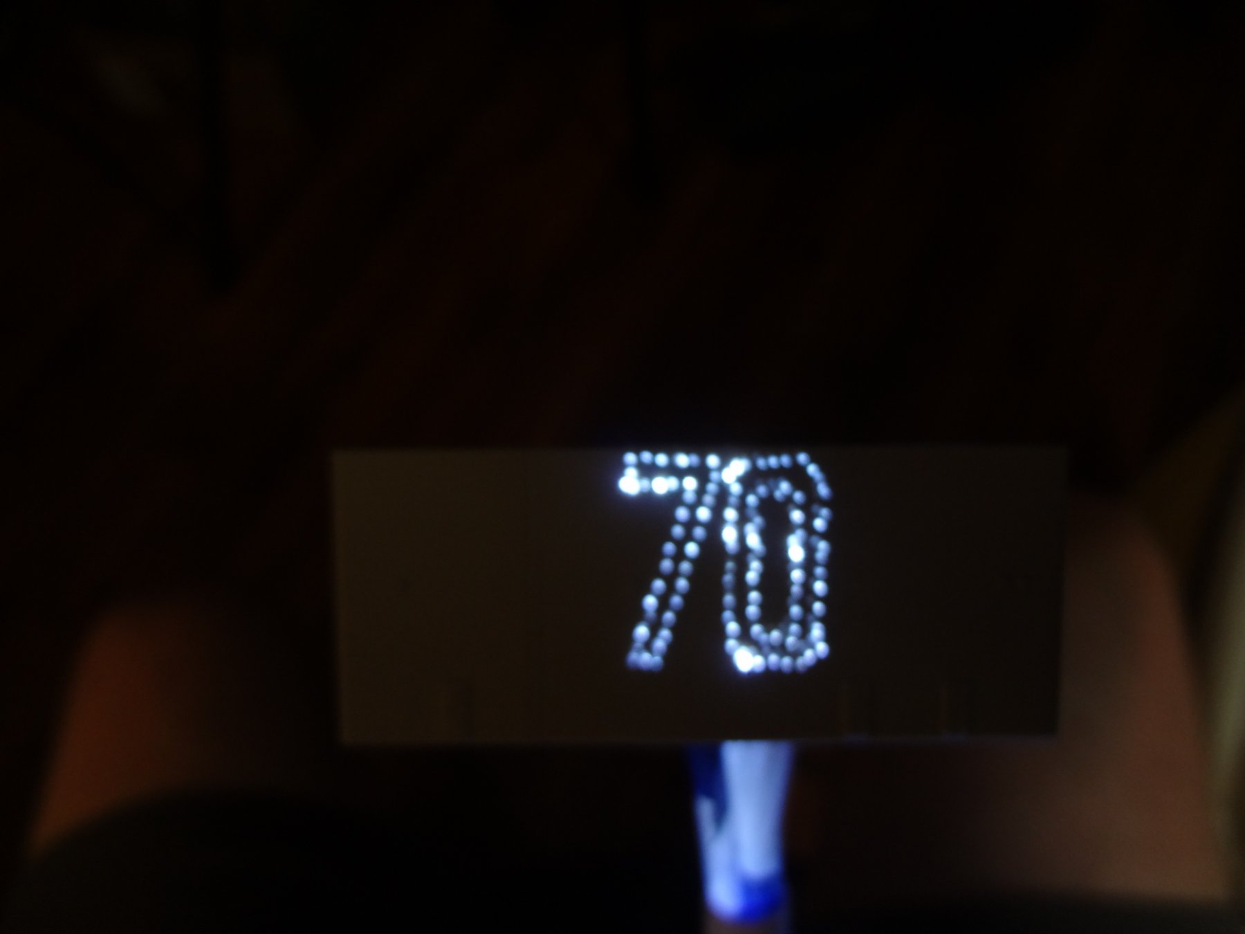
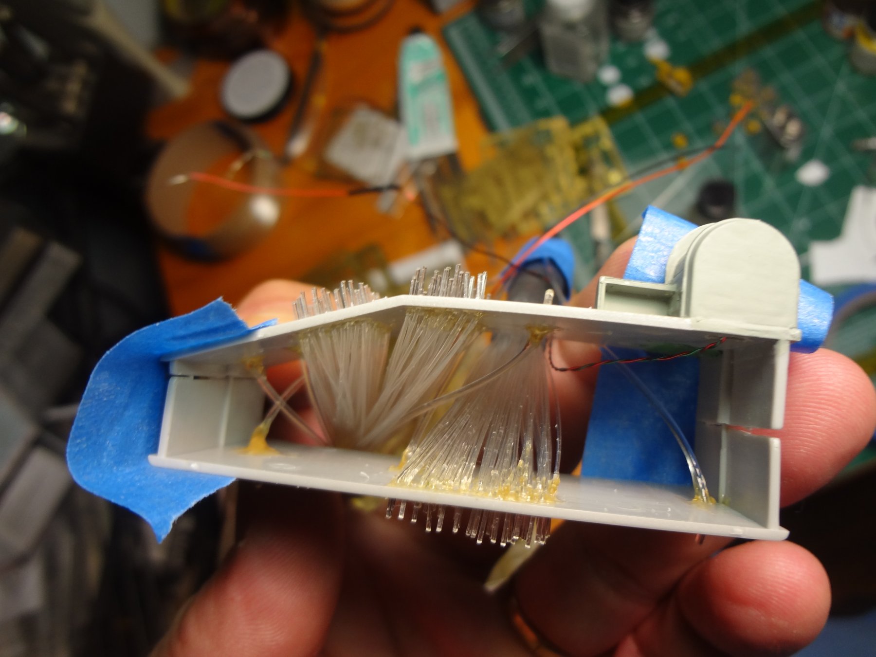
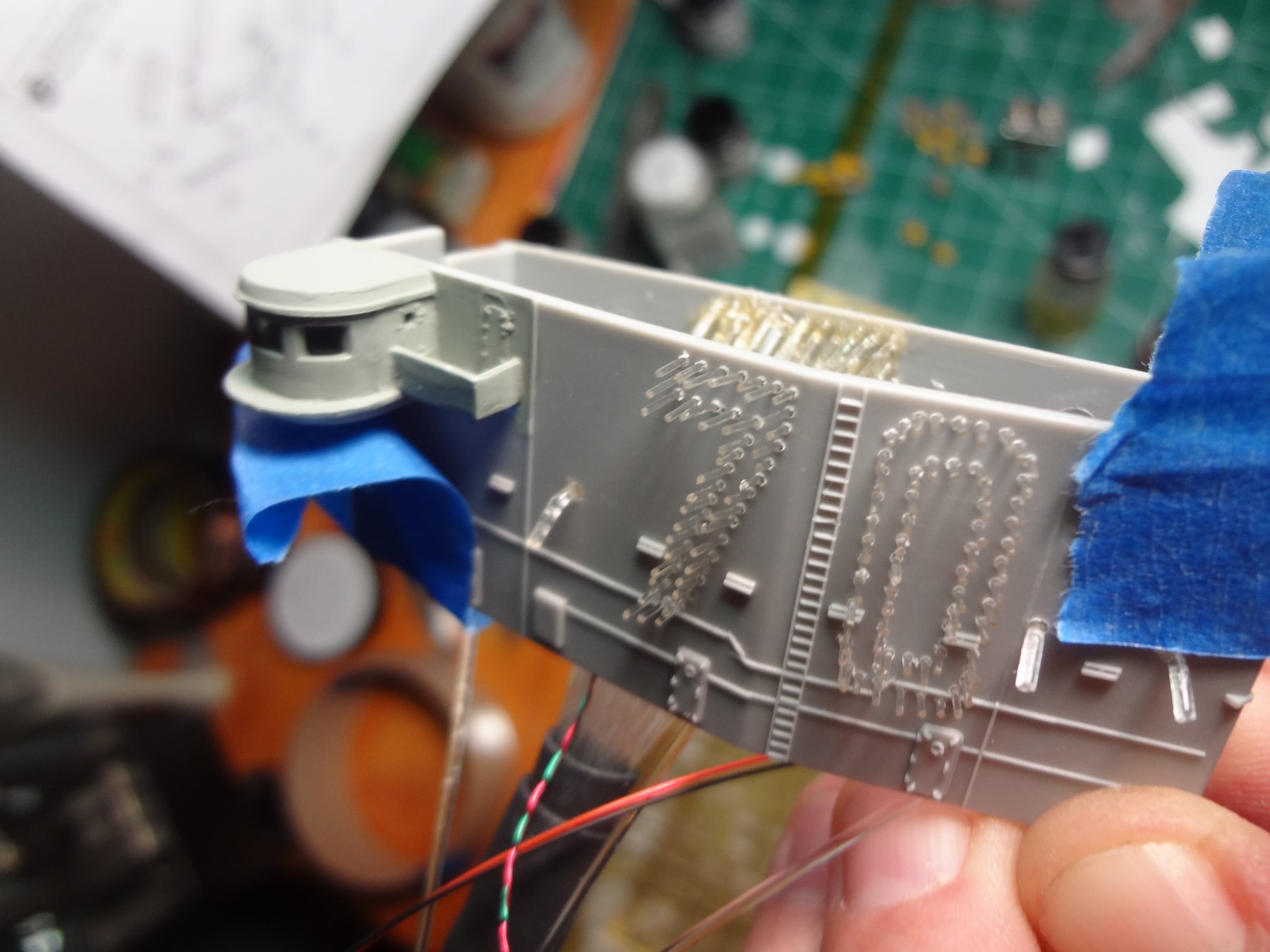
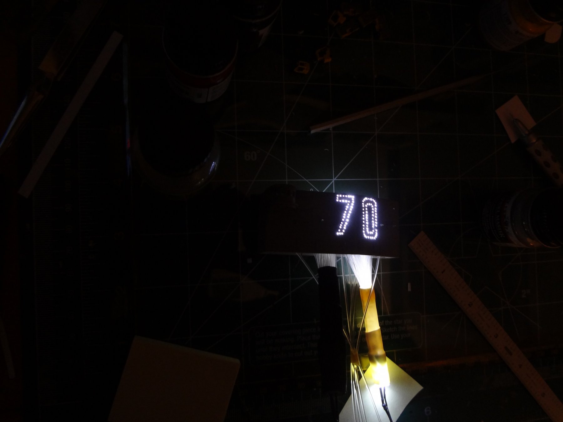
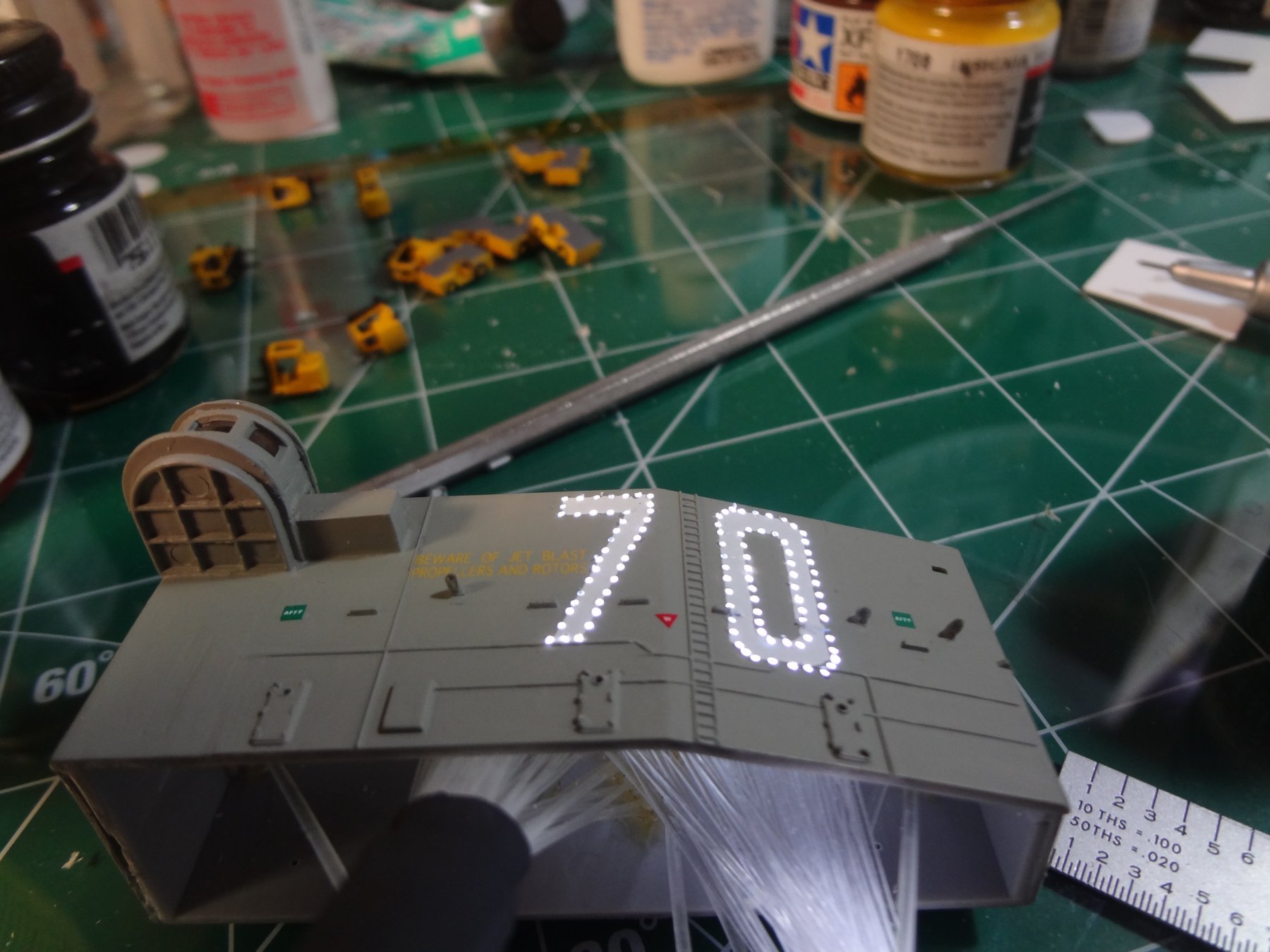
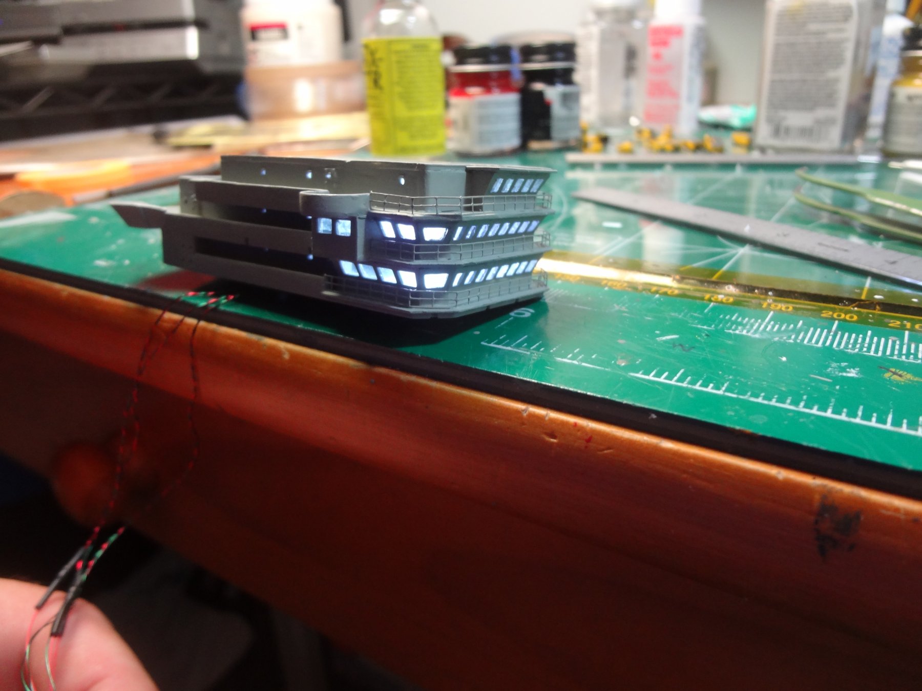
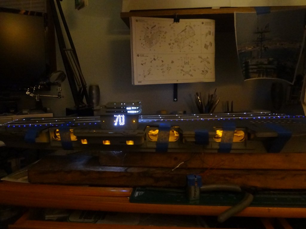
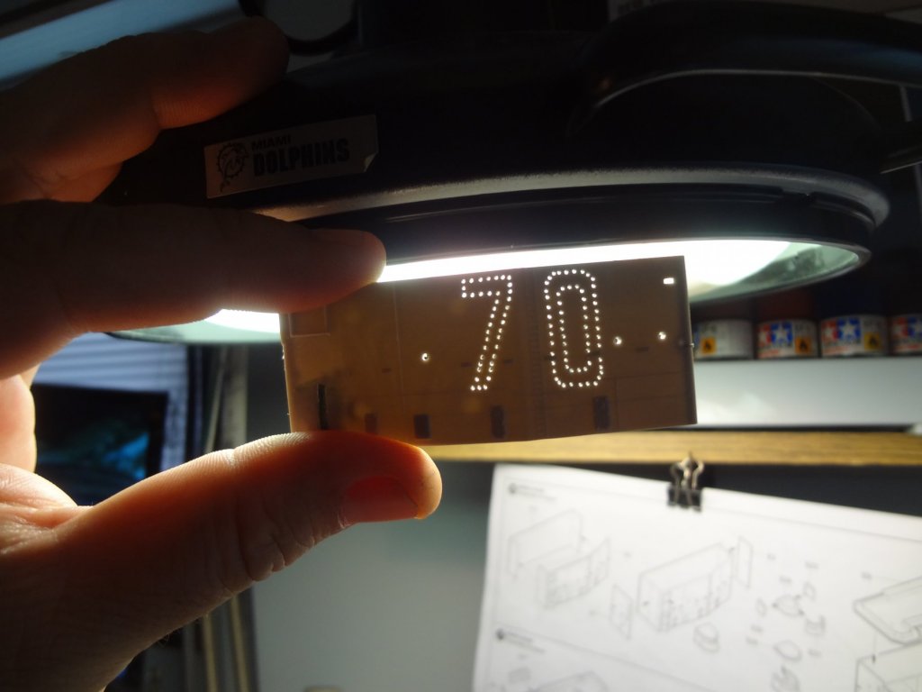
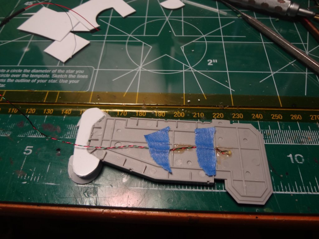
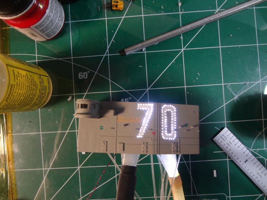
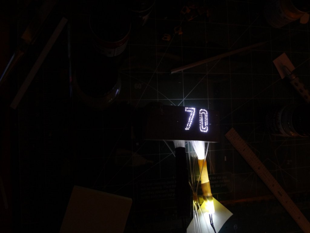
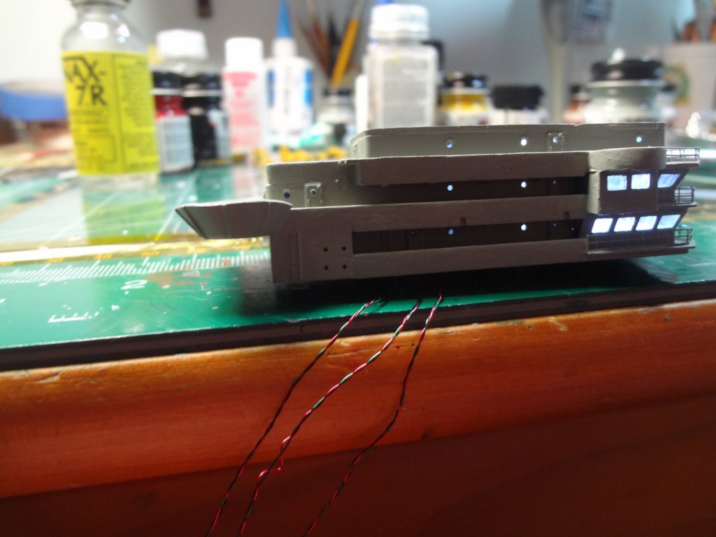
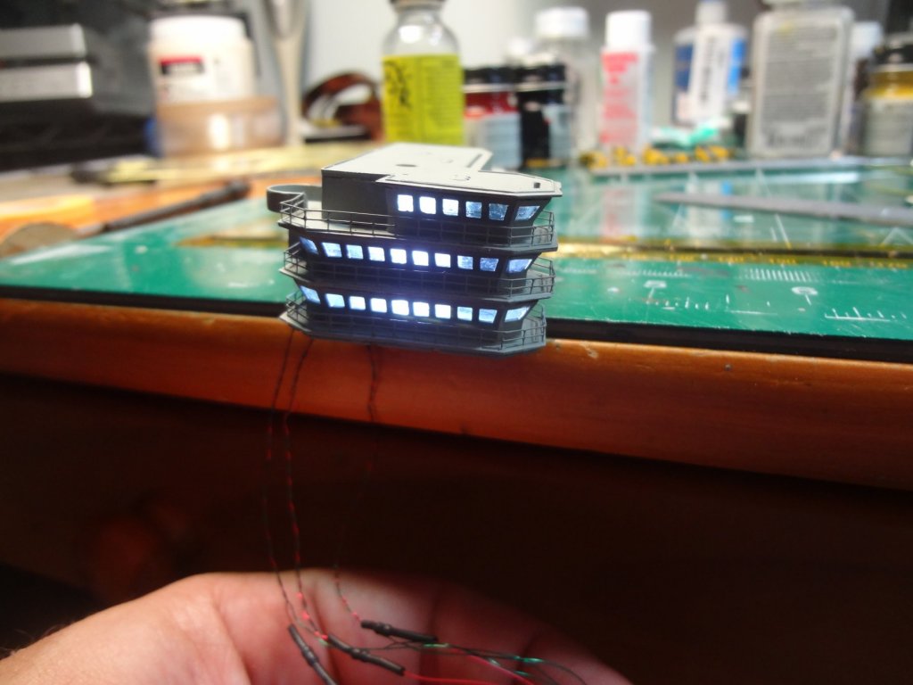
The island was then modified for the Vinson. I used .5mm fiber optics for the numbers and 1mm for the yellow deck lights. The holes were drilled straight and the fiber optics were angled at 45* as there was a little more room in the island. The decks were illuminated with white pico LED's. While typically these decks are illuminated in red, I chose to use white so the island stands out more. All the port holes were drilled out.


- 82 replies
-
- 8
-
-
- carl vinson
- trumpeter
- (and 2 more)
-
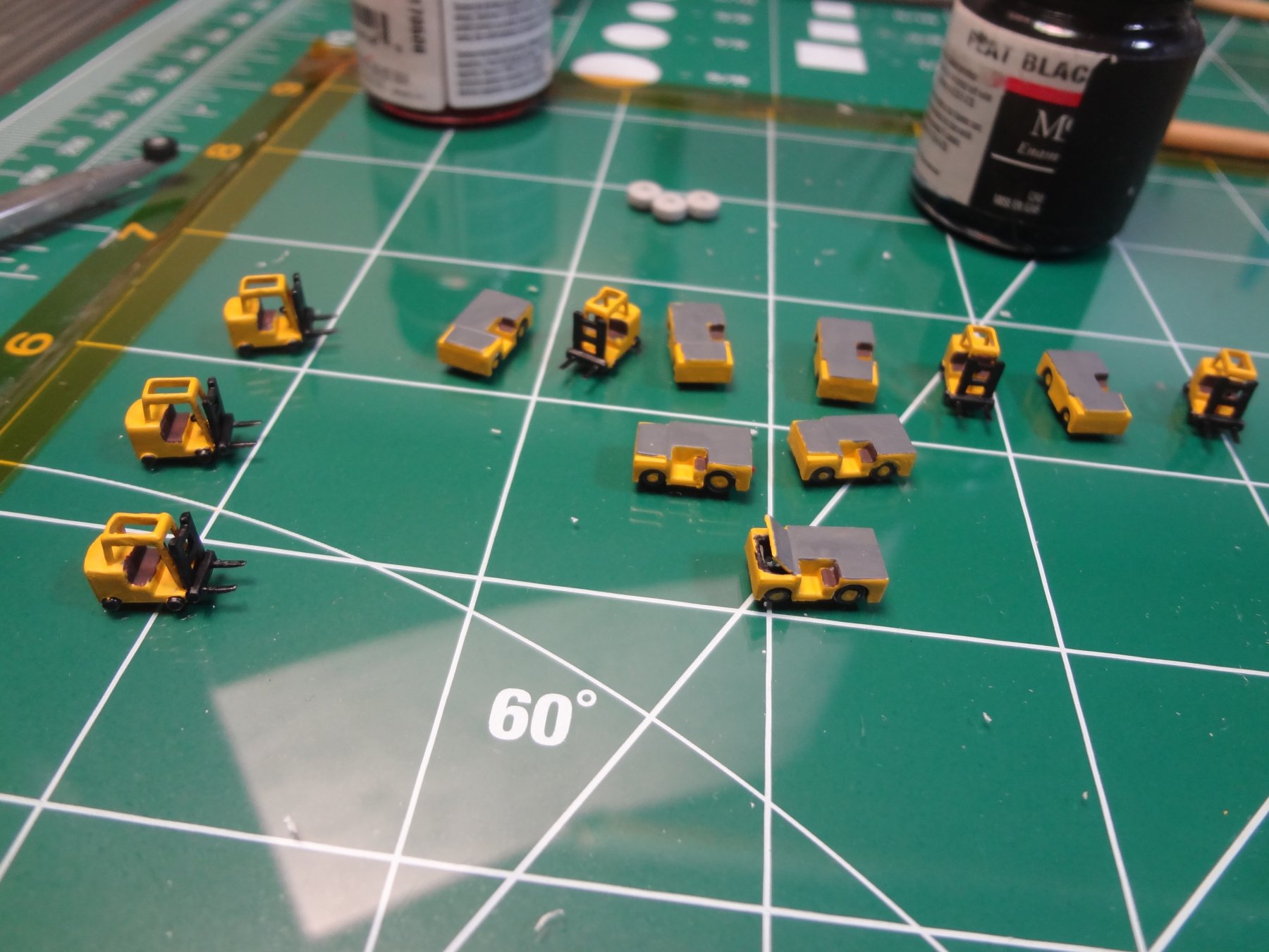
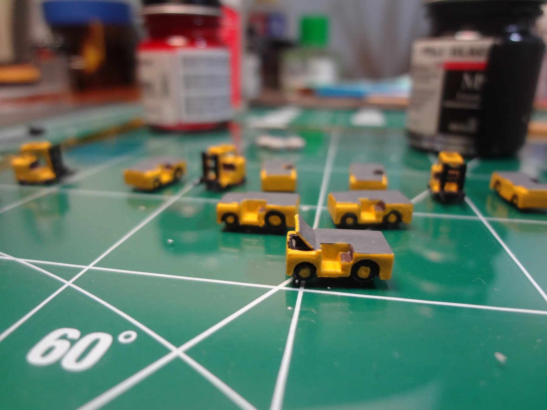
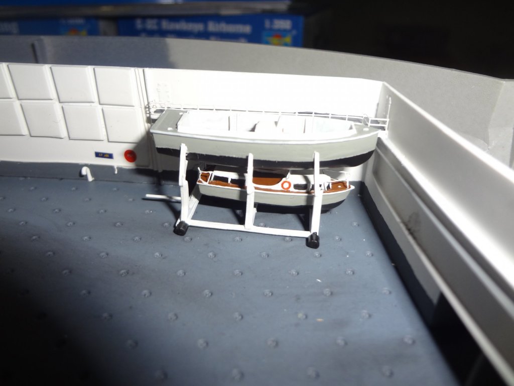
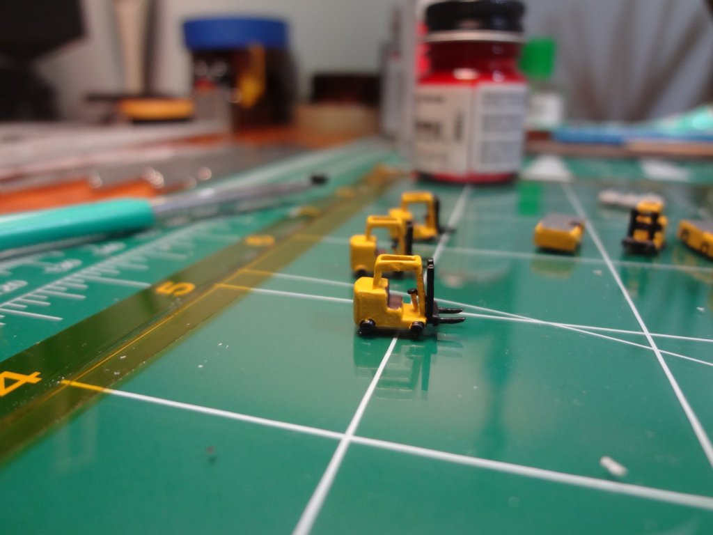
I then built the launches and used the kit deck tractors and fork lifts for the hangar bay. The resin deck tractors with the higher details will be used for the flight deck.


- 82 replies
-
- 6
-
-
- carl vinson
- trumpeter
- (and 2 more)
-
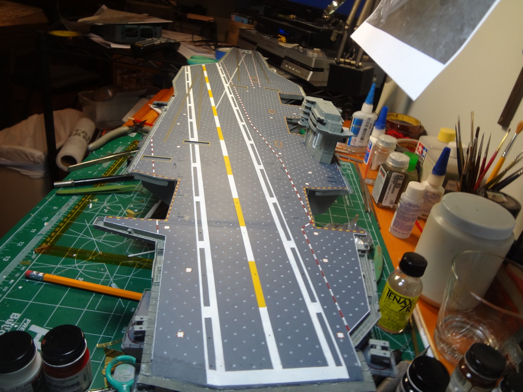
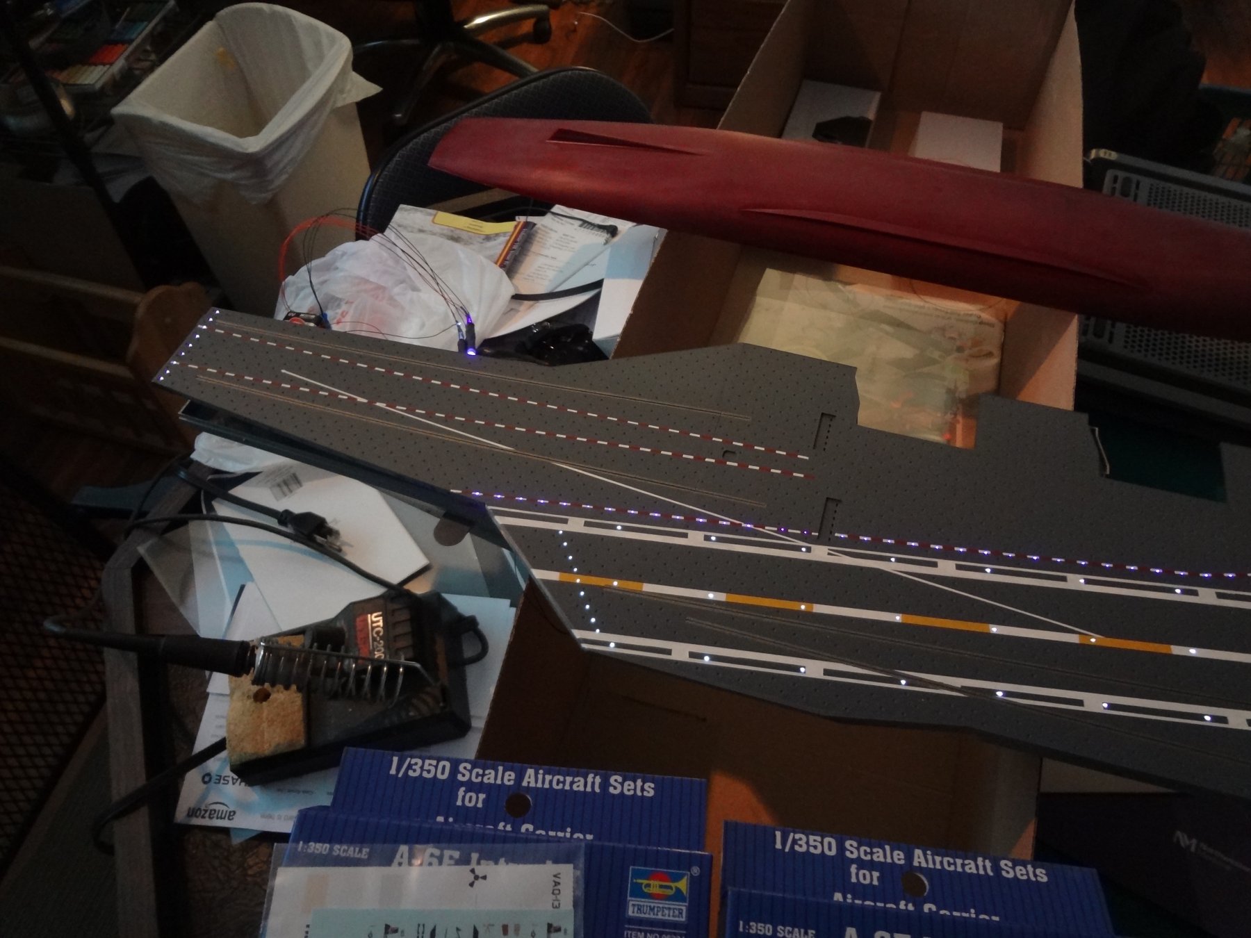
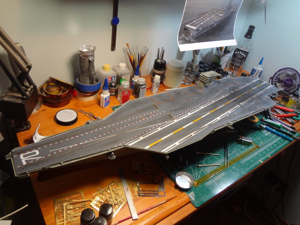
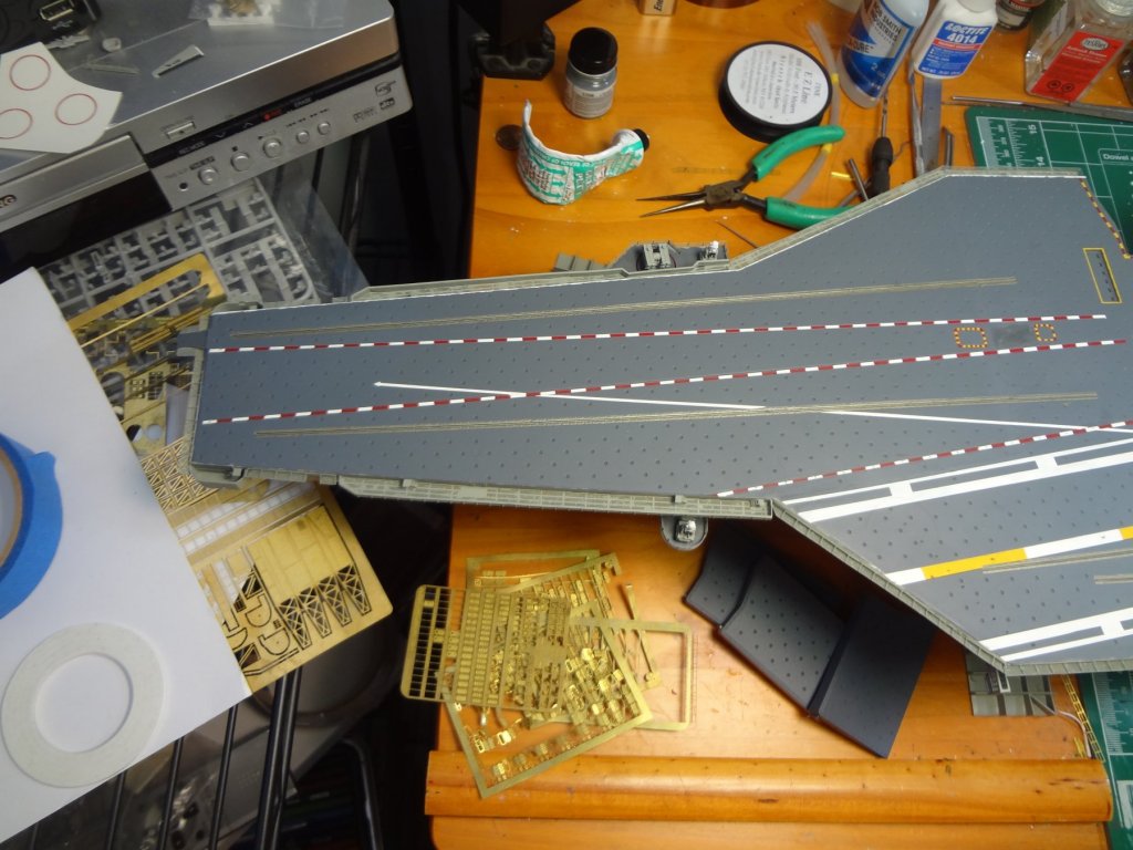
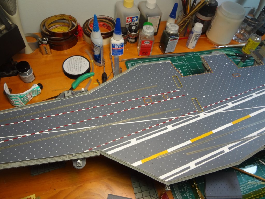
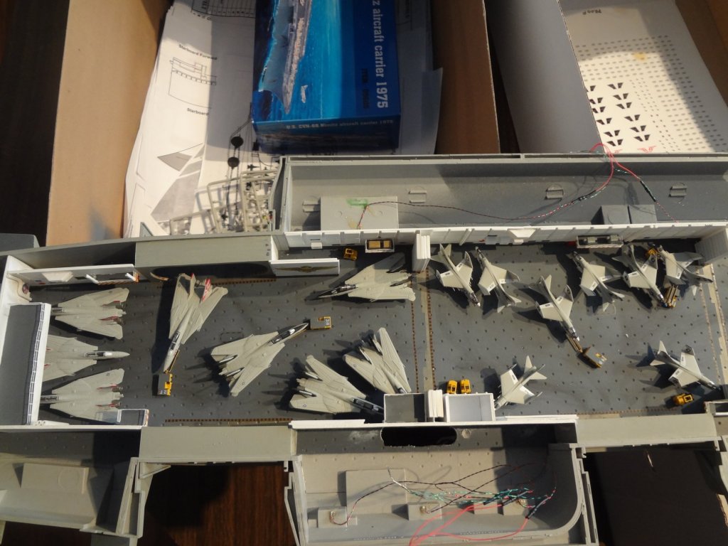
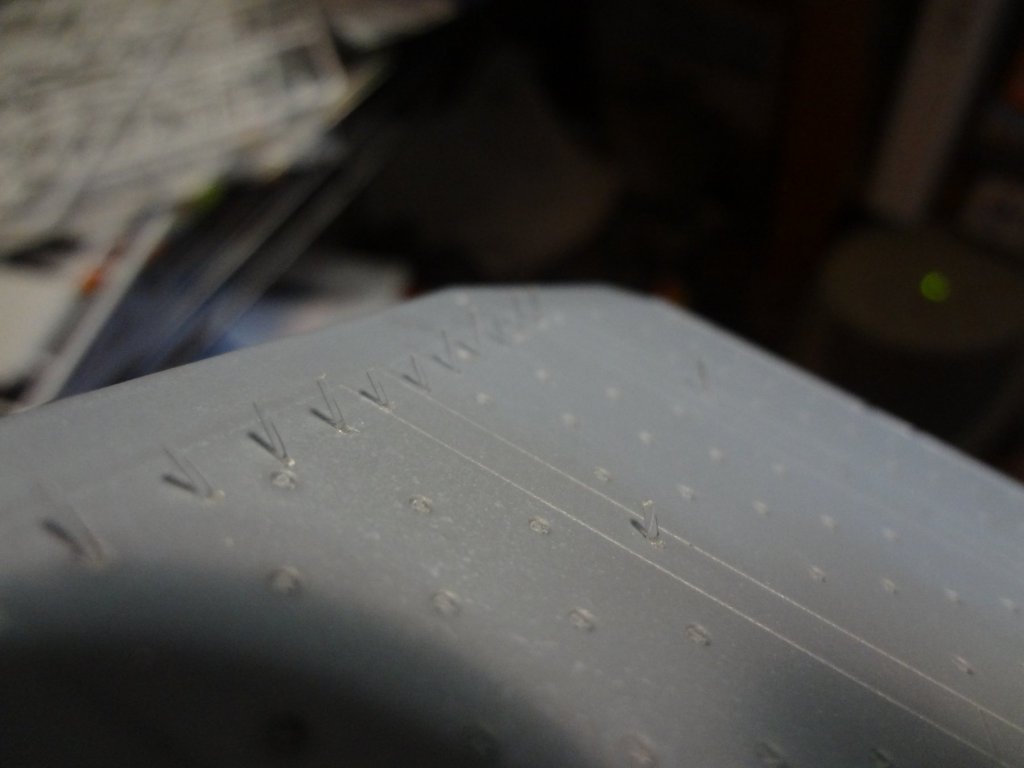
The flight deck was then painted (no decals used) and the fiber optic lines were trimmed flush.

- 82 replies
-
- 8
-
-
- carl vinson
- trumpeter
- (and 2 more)
-
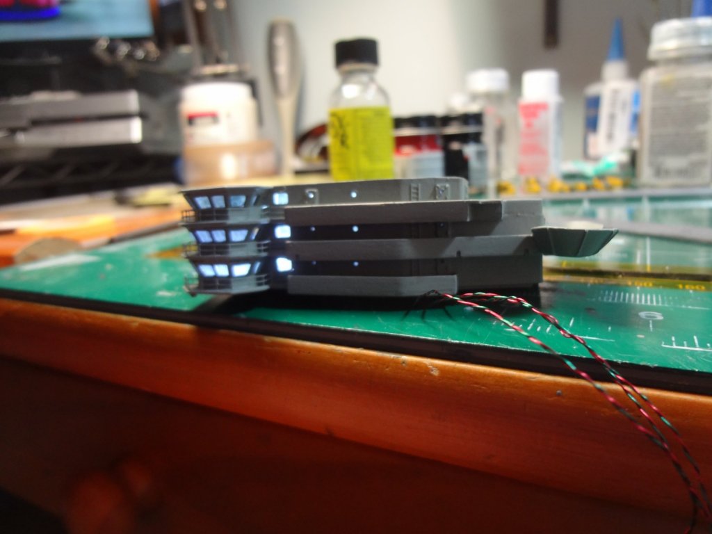
I took two sheets of clear sheets and added 19 micro LED's to make the hangar bay roof. Here is a dry fit test to see how the bays will look .


- 82 replies
-
- 4
-
-
- carl vinson
- trumpeter
- (and 2 more)
-
Thanks, I do not remember the big cans and do not show them in my limited photo's. Where were they? Which hangar bay were they in? Unfortunately At this point in the project I may not be able to include them based on location.
- 82 replies
-
- 3
-
-
- carl vinson
- trumpeter
- (and 2 more)
-
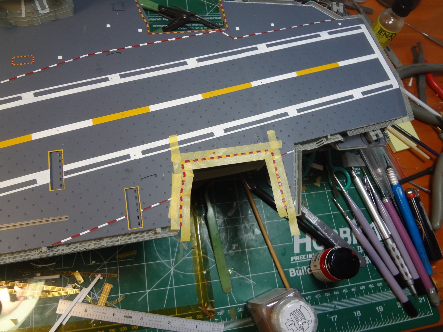
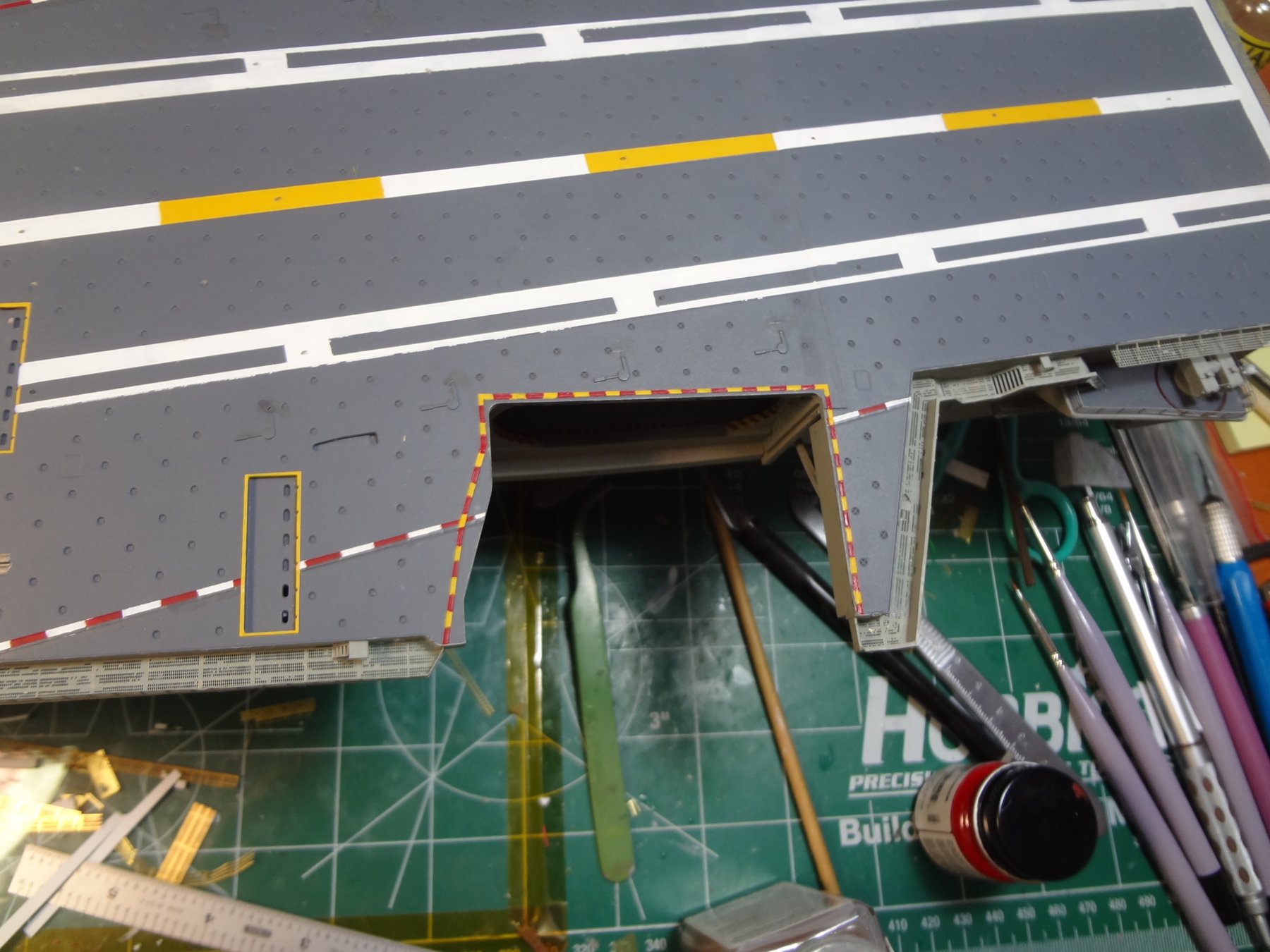
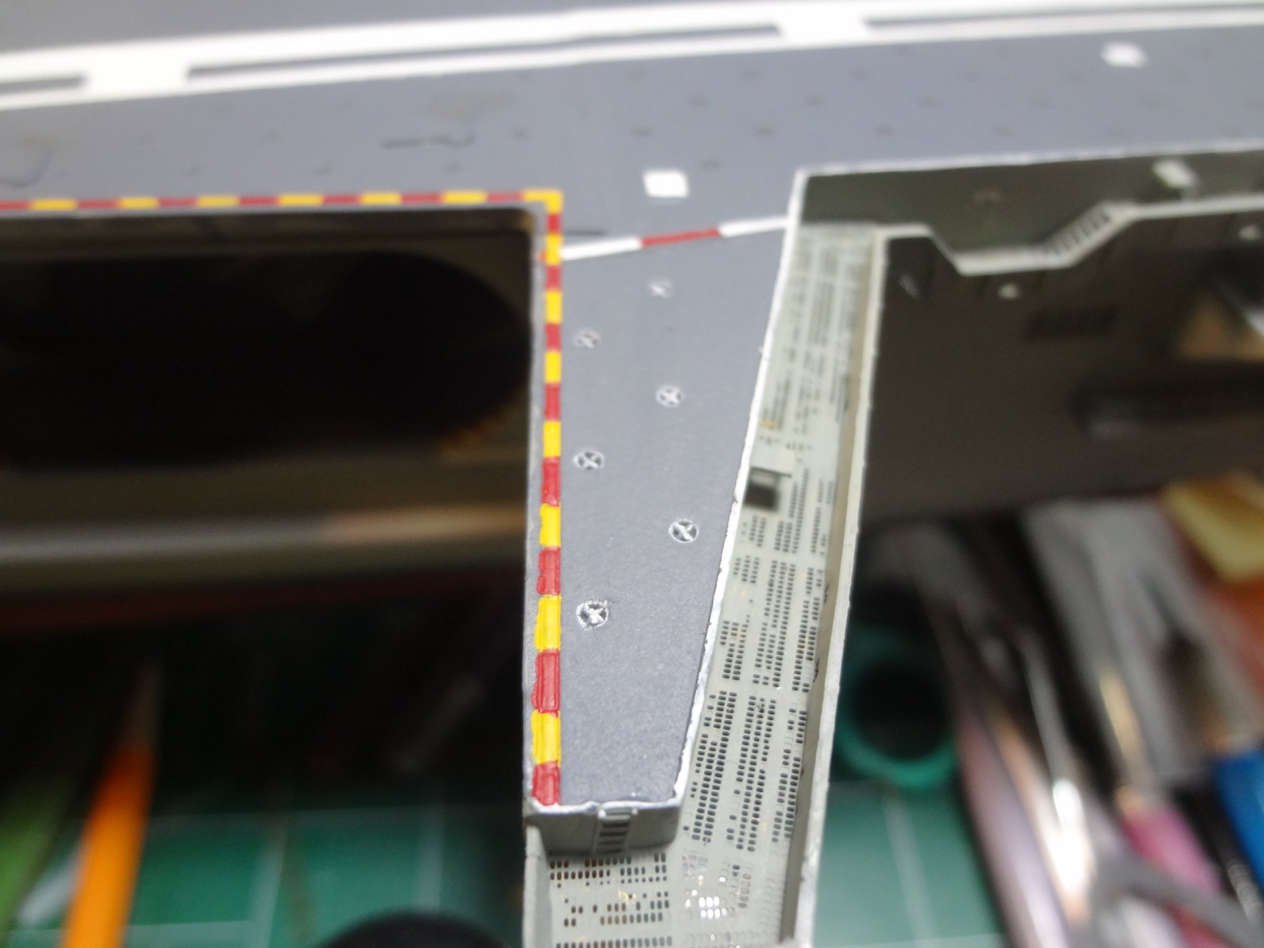
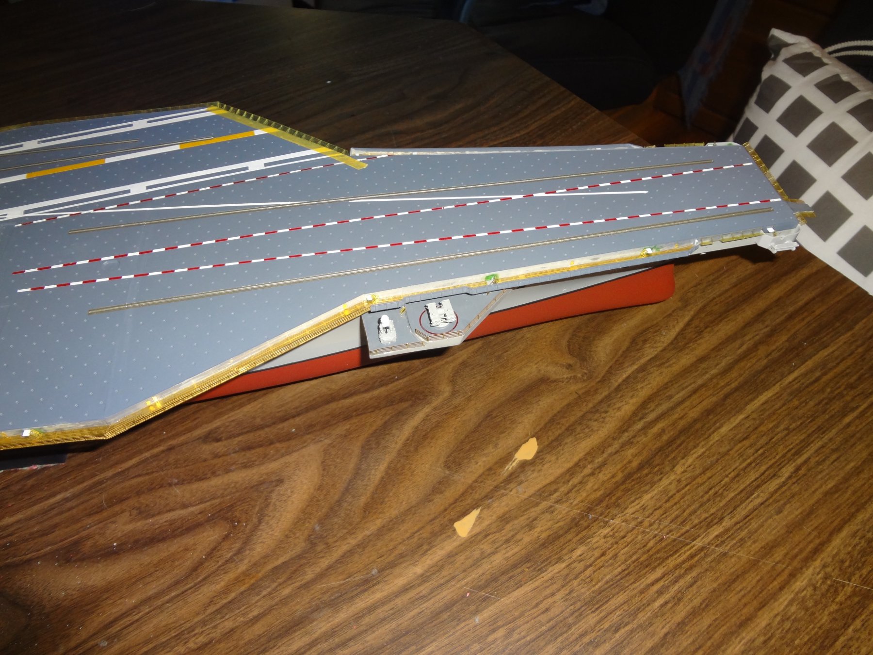
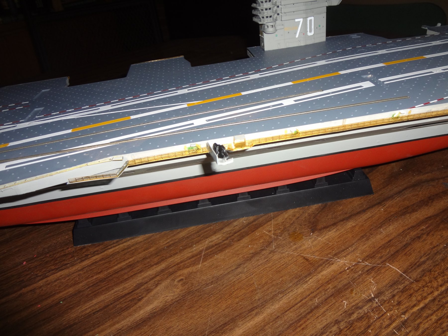
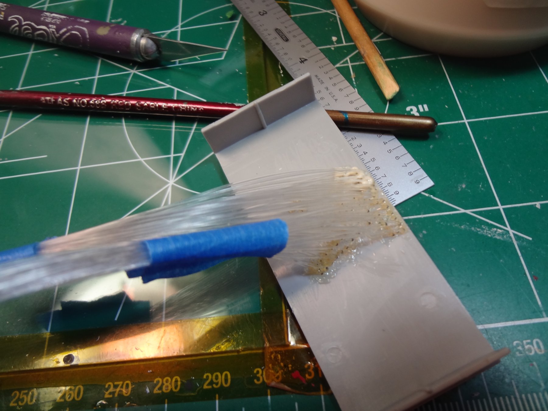
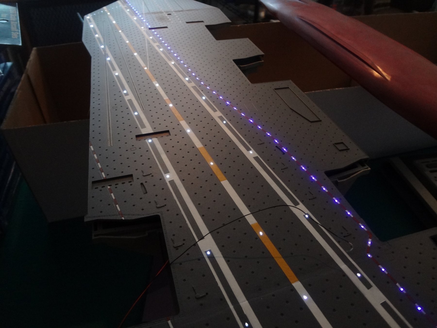
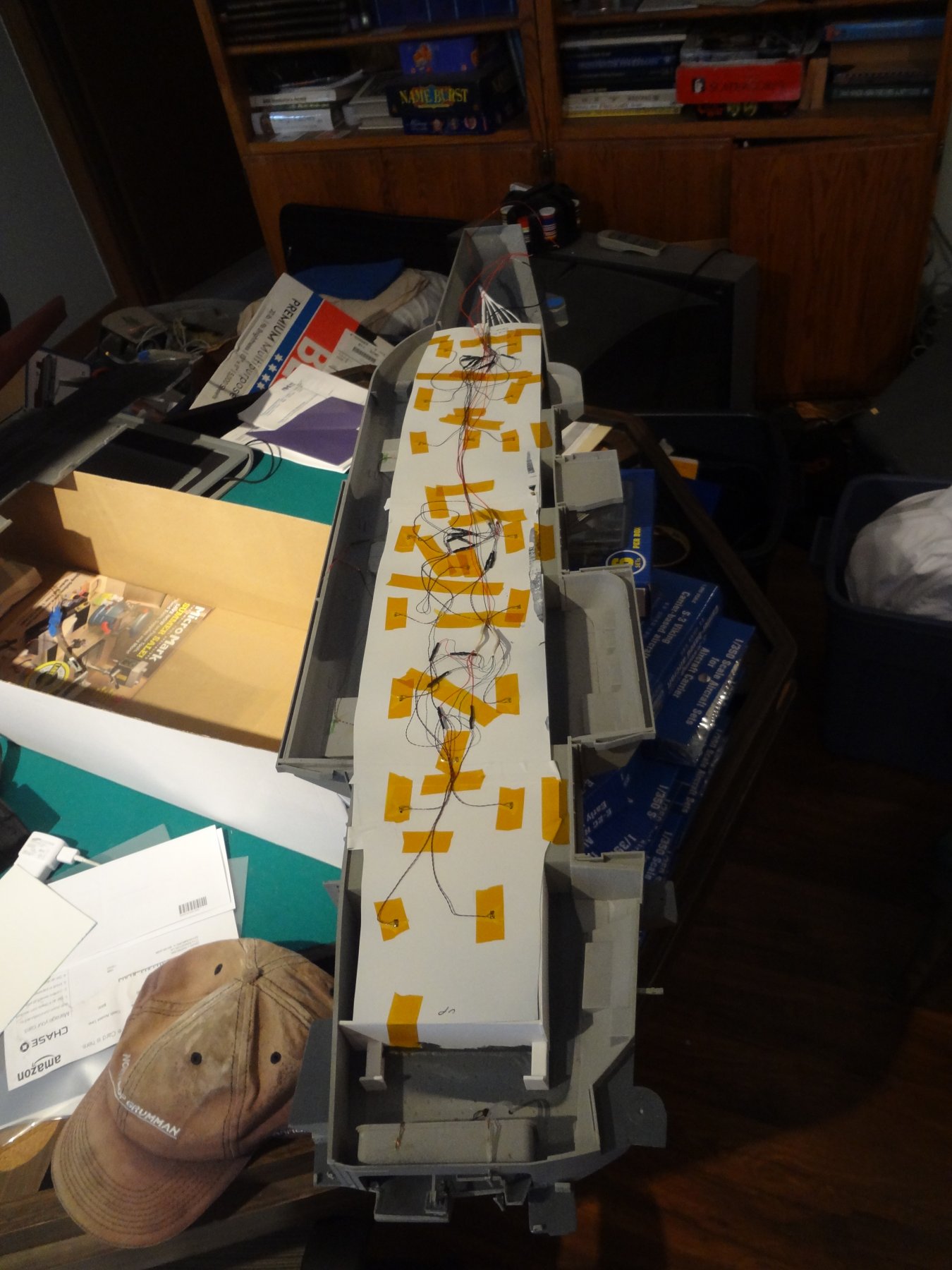
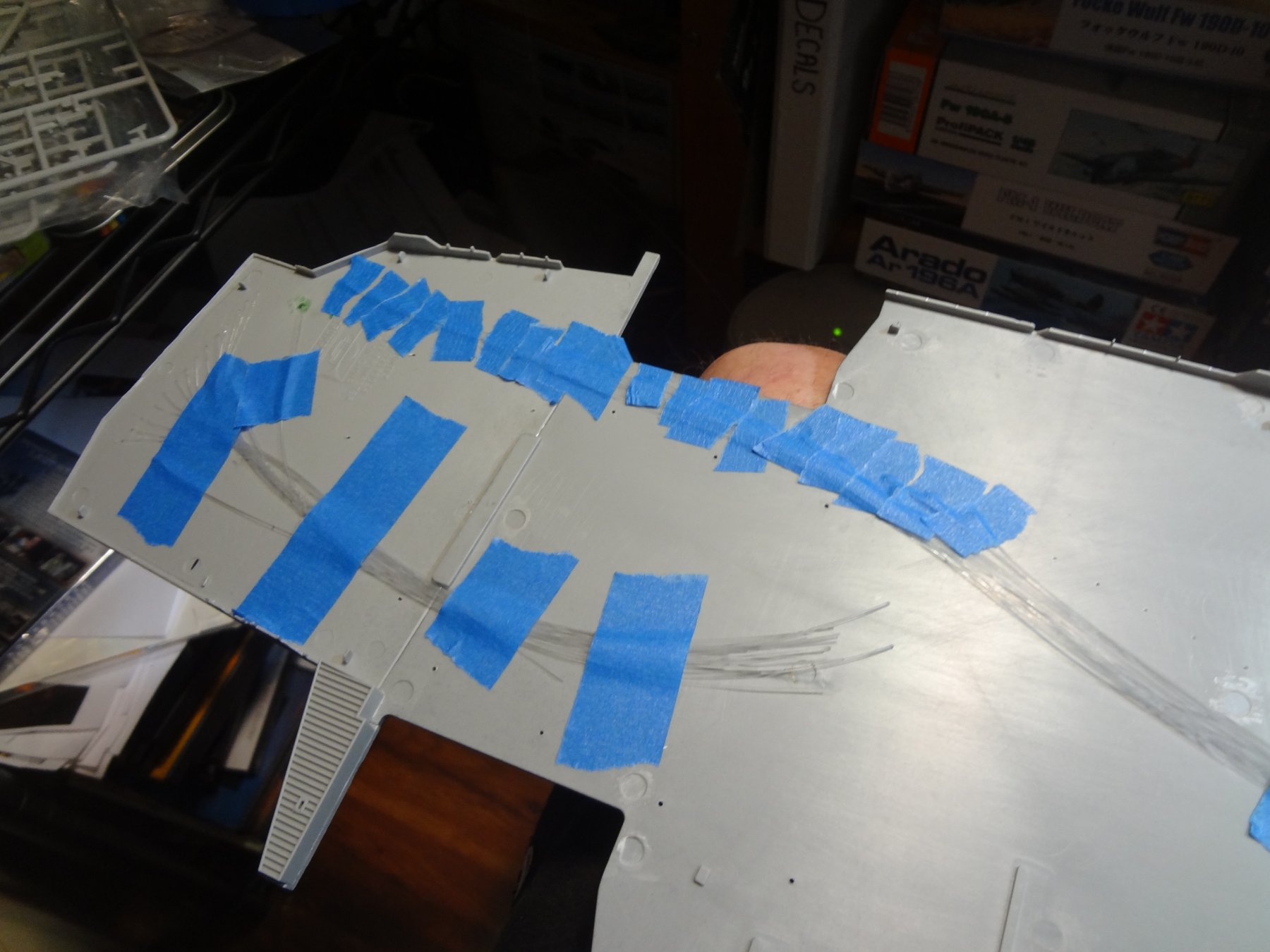
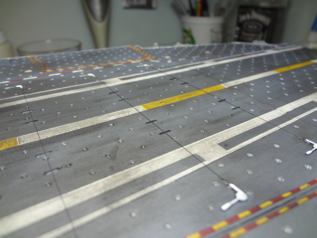
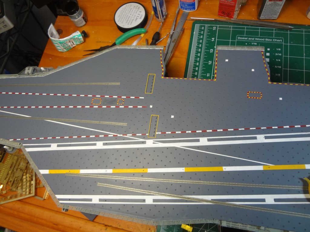
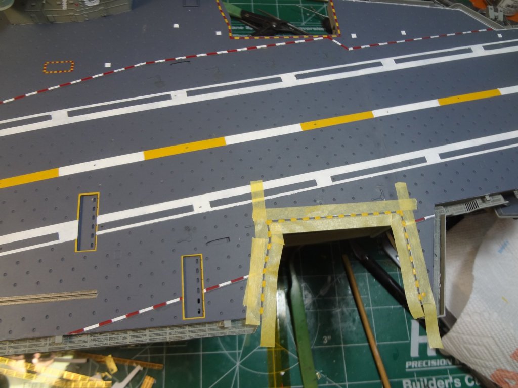
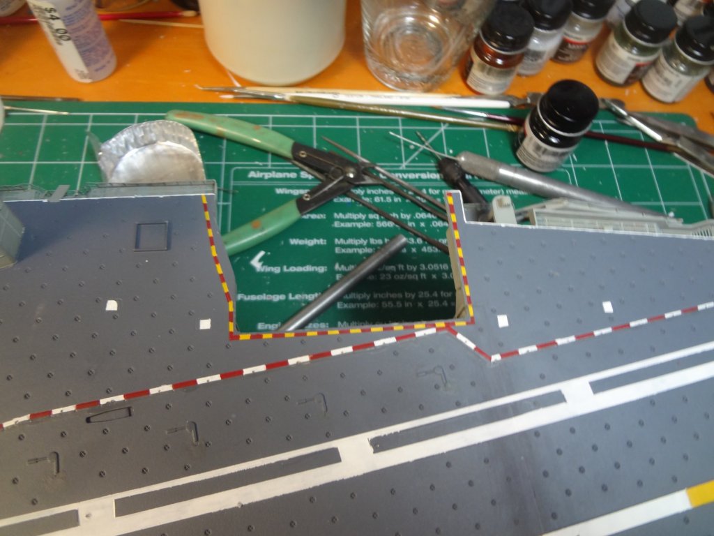
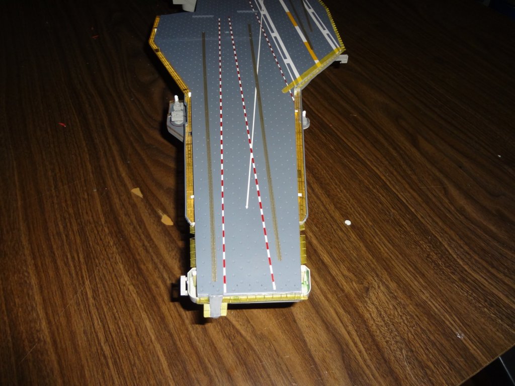
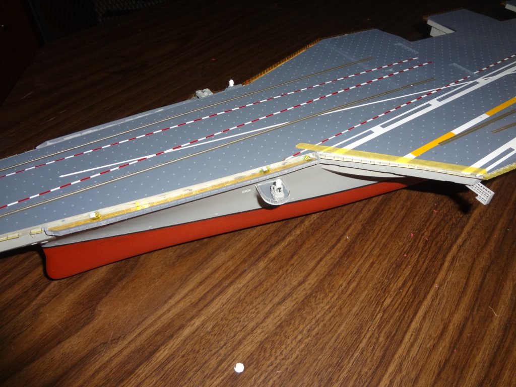
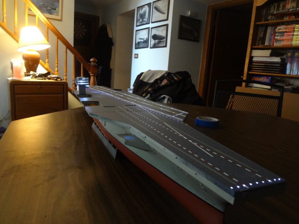
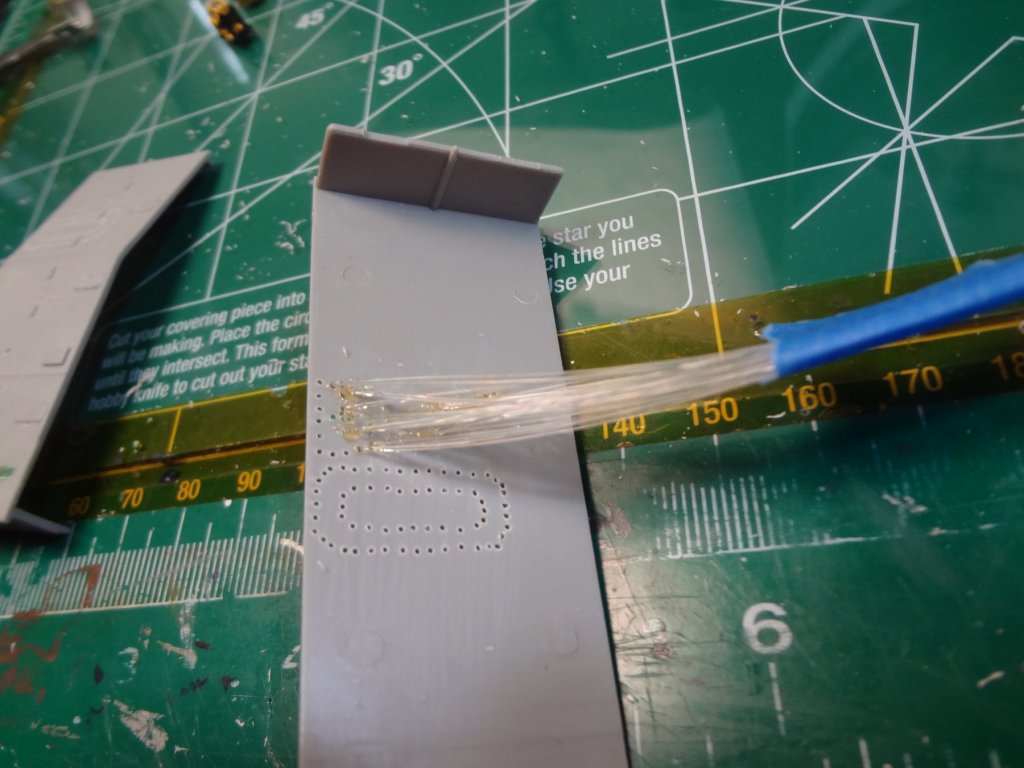
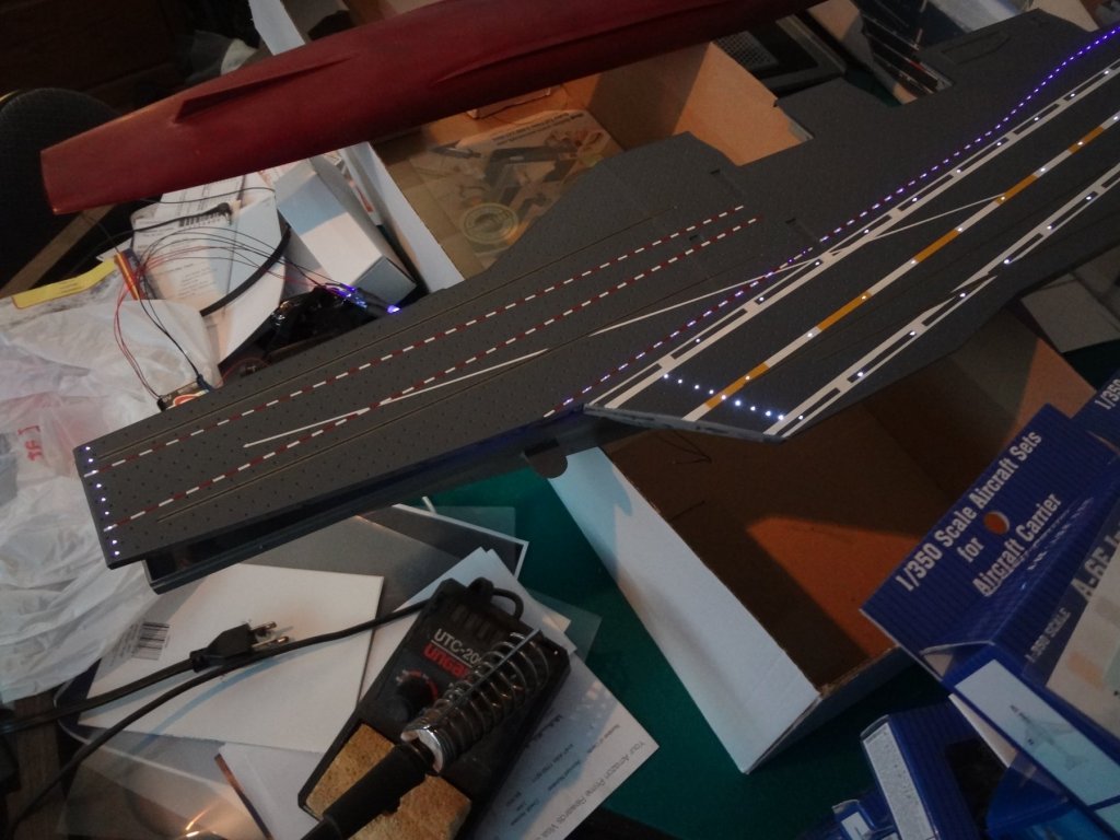
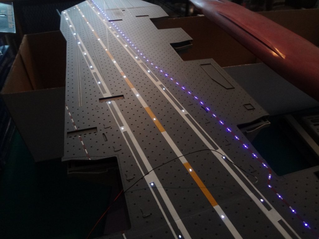
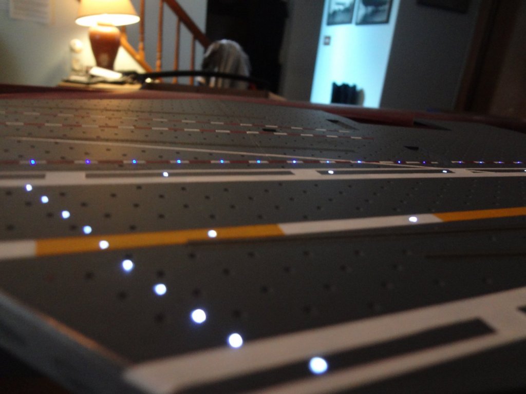
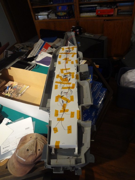
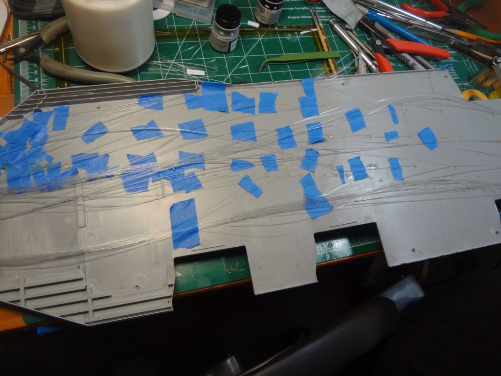
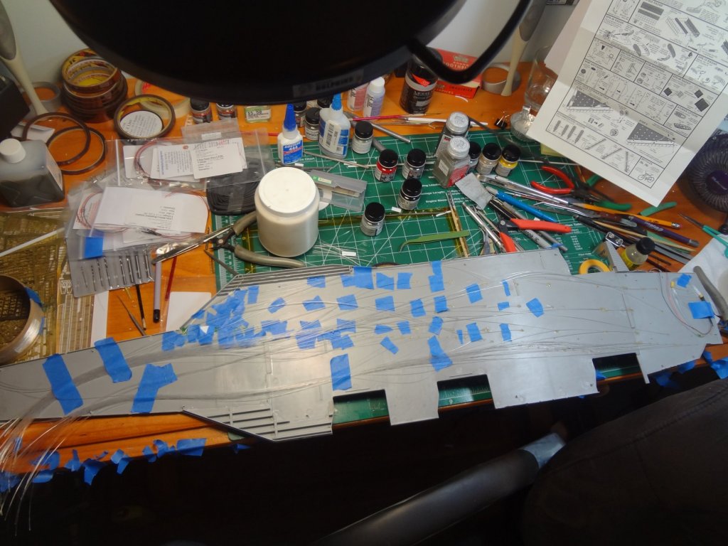
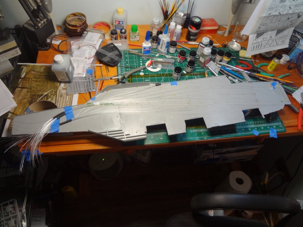
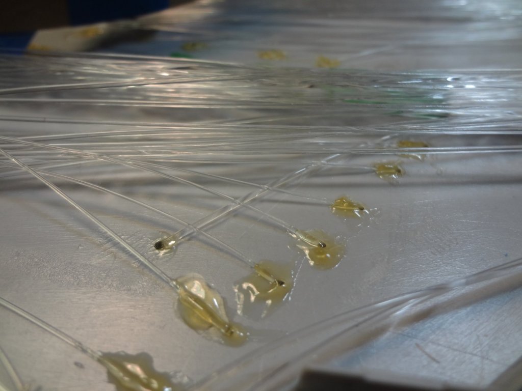
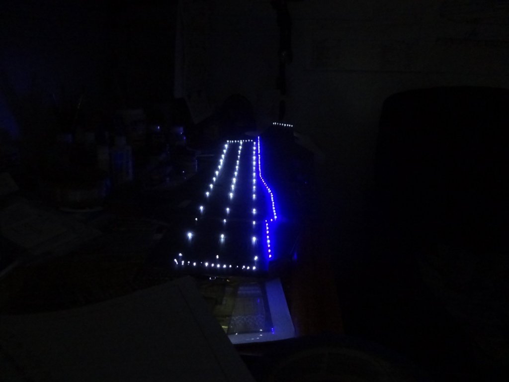
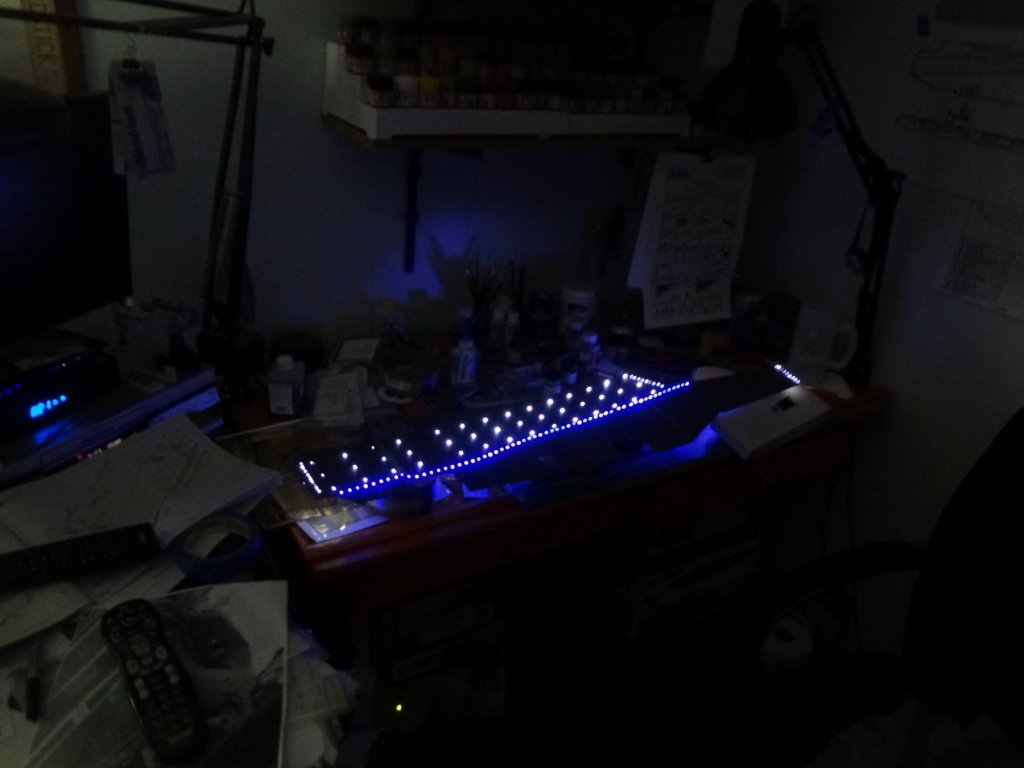
On to the flight deck. I am illuminating the runway and the foul line. The runway is done with .75mm fiber optic lines and the stern, bow, and foul line is with .5mm fiber optic lines. To install the fiber optic lines the holes are drilled at a 45* angle. This is required because the fiber optic lines cannot bend 90* or they will crack. I needed the lines to sit flush to the bottom due to only a 1.25mm space between the bottom of the flight deck and the roof of the hangar bays. To hold the optic lines in place I used acrylic gel medium. super glue makes the fiber optic lines extremely brittle. The acrylic gel dries clear and has some flexibility to provide strain relief while handling and routing the lines. I also mounted the lines to stick up about 5mm. The reason for this is it allows me to paint and weather the deck then trim them so they are flush and nearly invisible. The illuminated photos look brighter due to the camera and the section of the fiber optic lines sticking out above the deck.

- 82 replies
-
- 12
-
-
- carl vinson
- trumpeter
- (and 2 more)
-
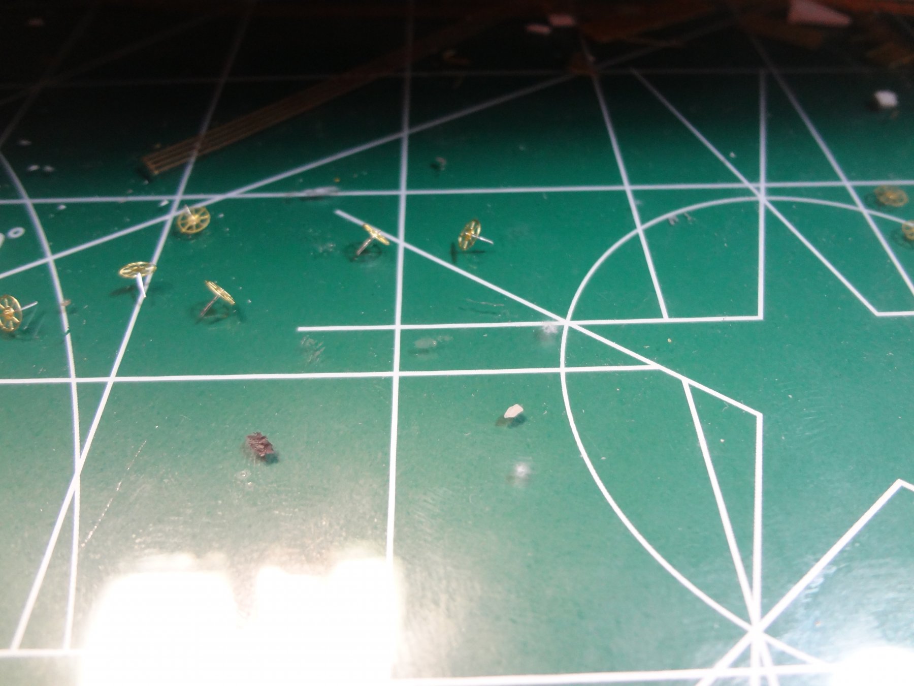
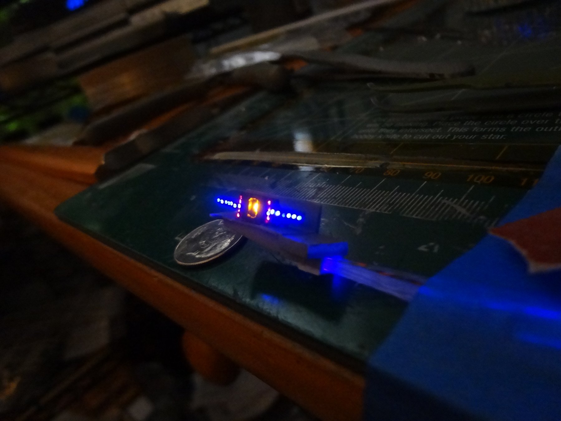
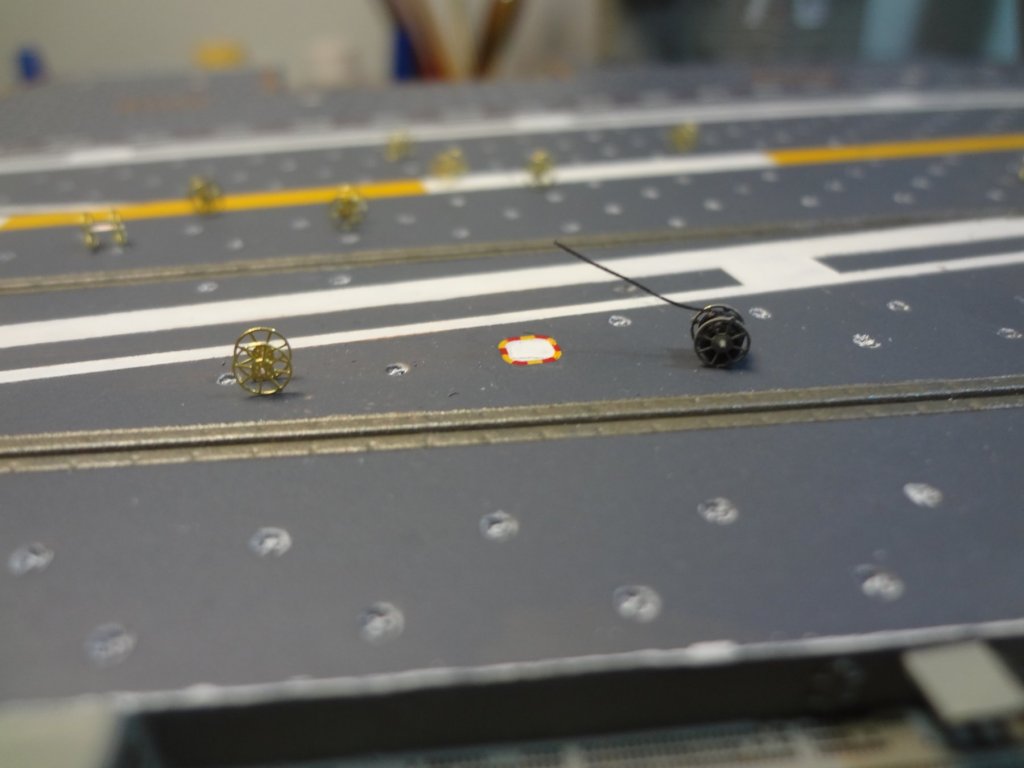
On aircraft carries there is a Fresnel lighting system to aid the pilots for landing. This is nicknamed "The Ball". Typically you will hear the pilot "Call the Ball" on approach. This is a visual aid so the pilot can keep their aircraft in the proper landing lane. I scratch built the Fresnel lighting by using a pico LED for the center (the ball) and .5mm fiber optics for the blue and red warnings. It took about 5 tries before I was able to get all the fiber optic lines to fit and route where I needed them.

- 82 replies
-
- 7
-
-
- carl vinson
- trumpeter
- (and 2 more)
-
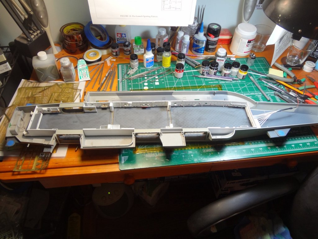
The hangar deck and doorways were weathered and stained.
- 82 replies
-
- 9
-
-
- carl vinson
- trumpeter
- (and 2 more)
-
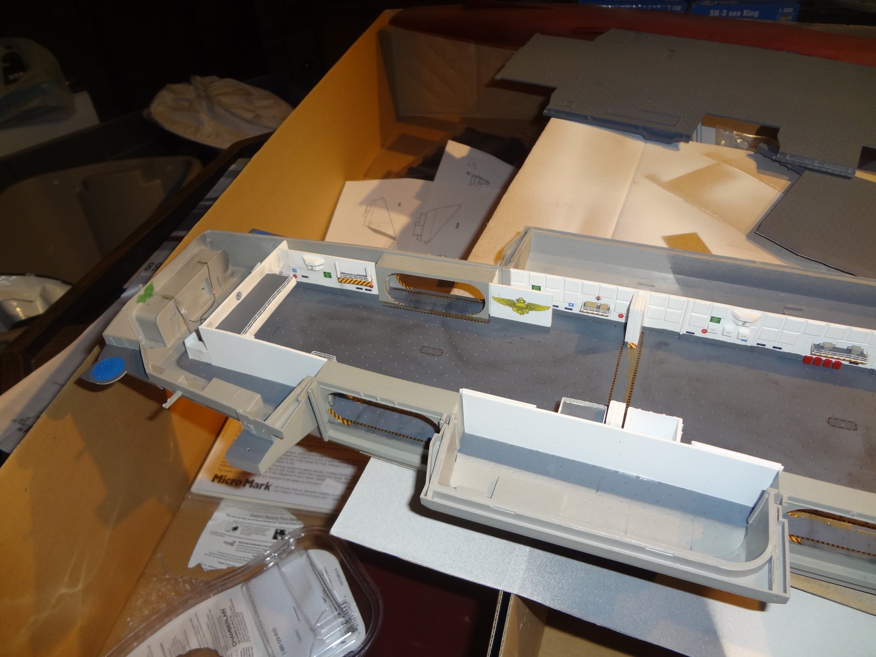
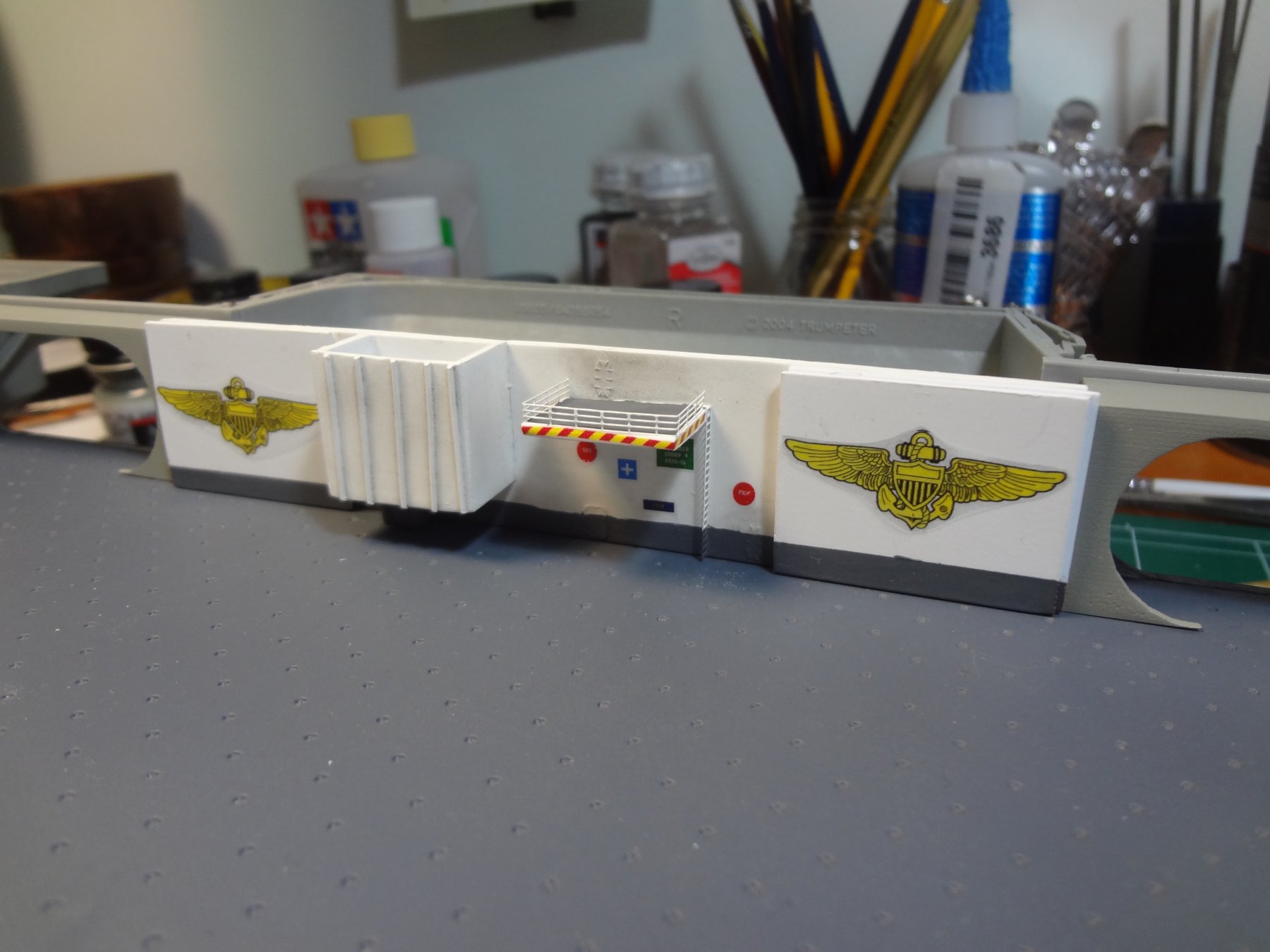
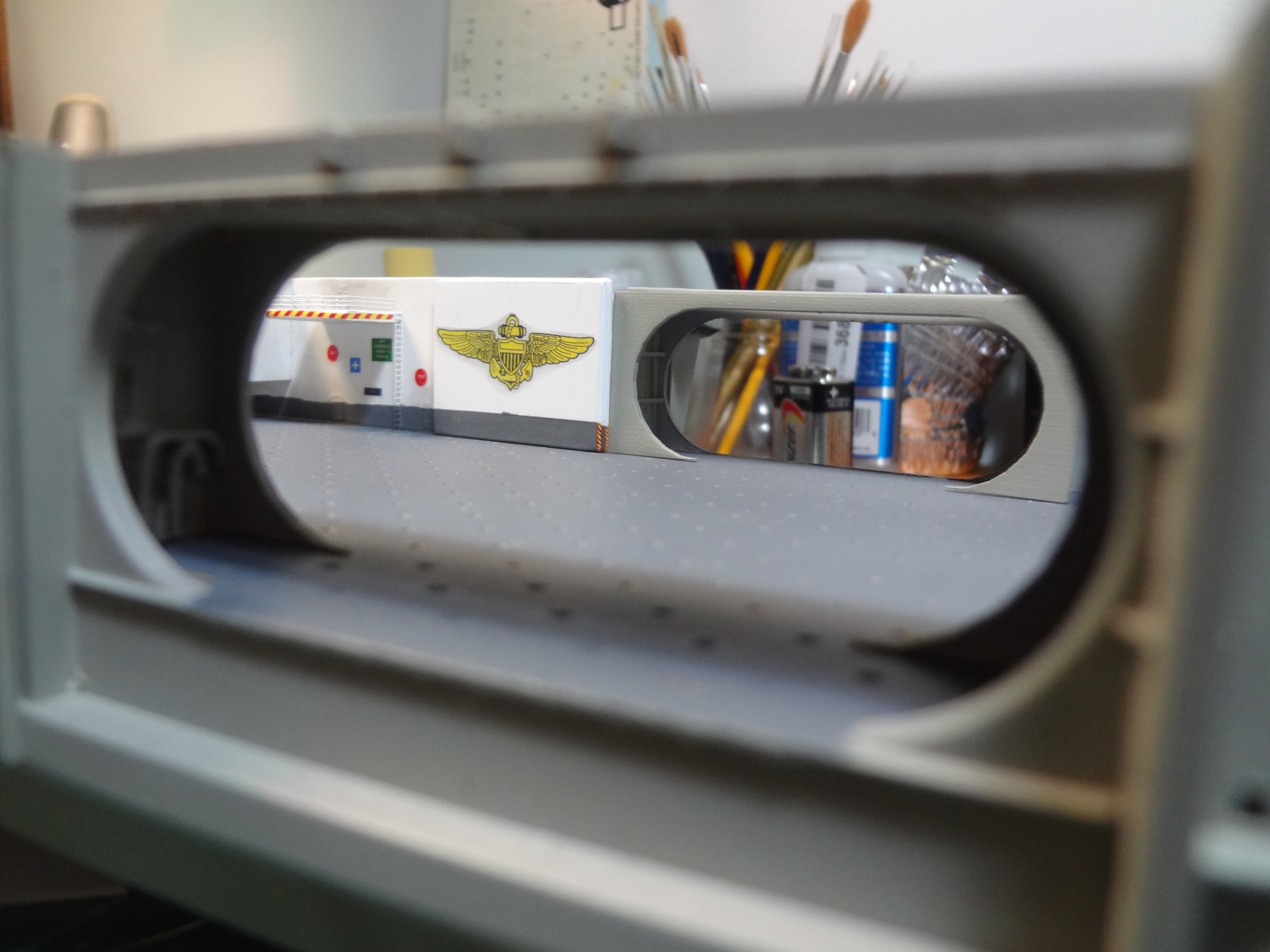
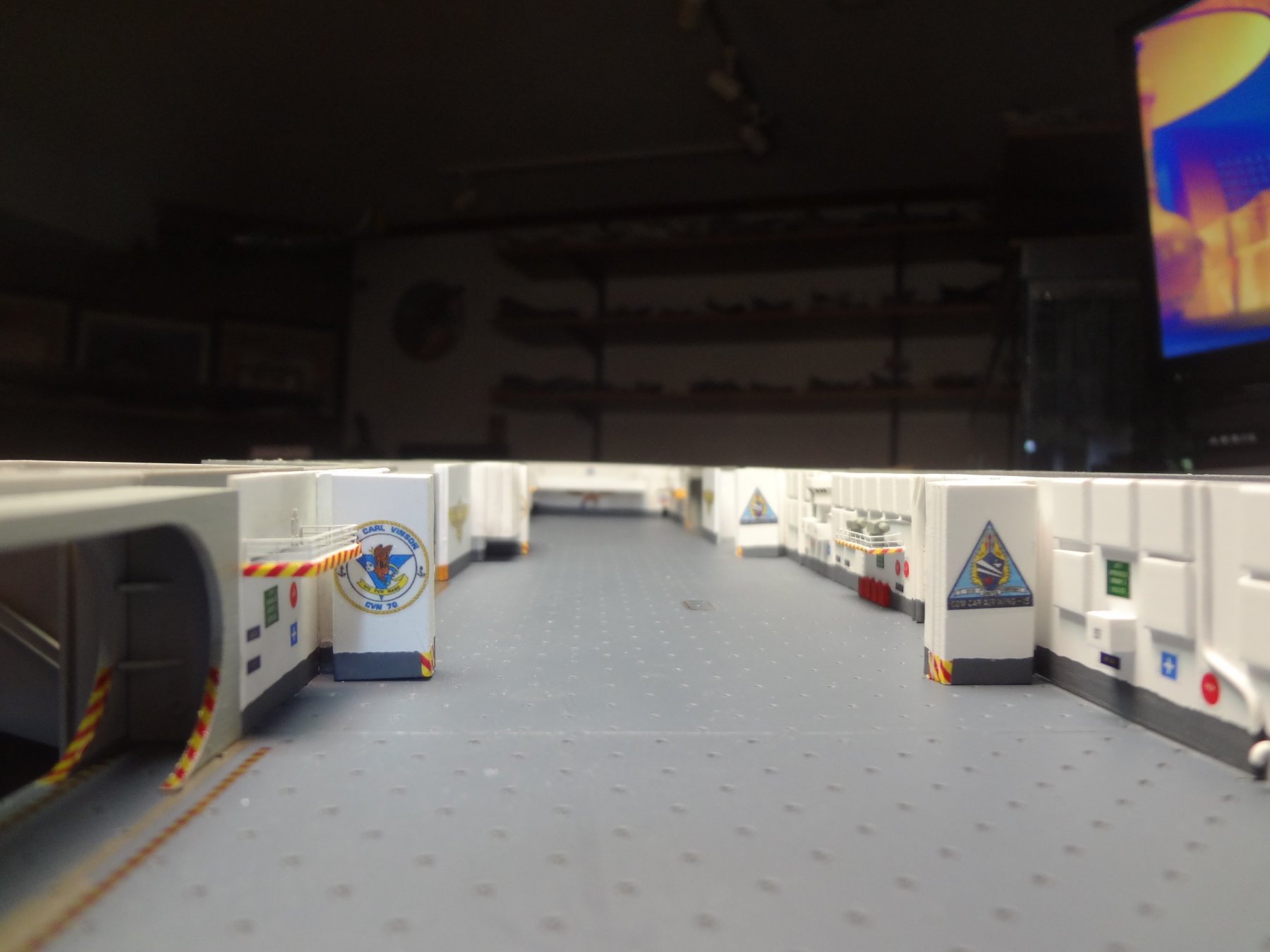
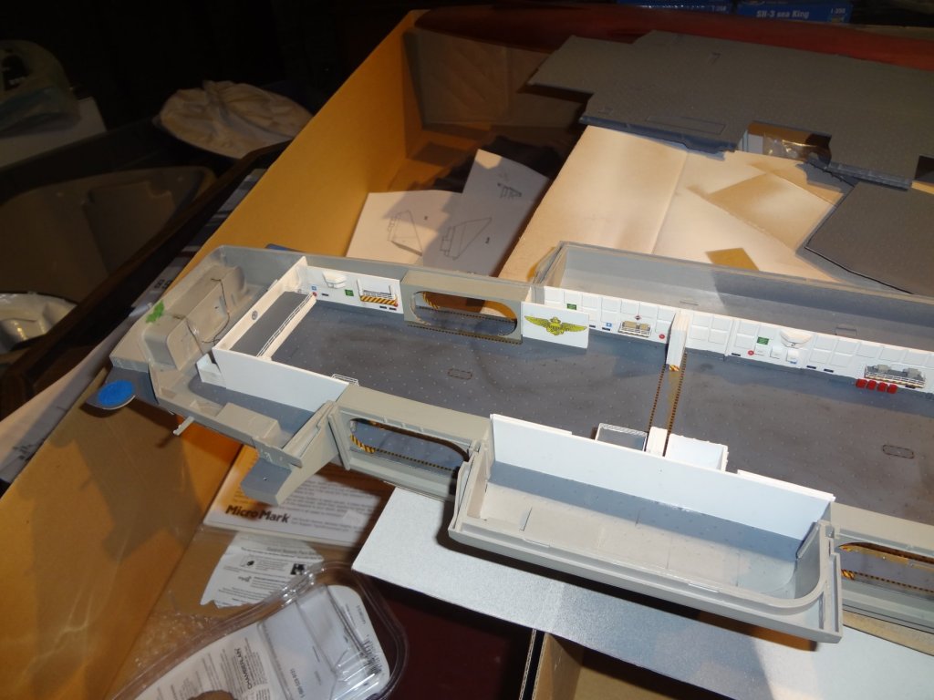
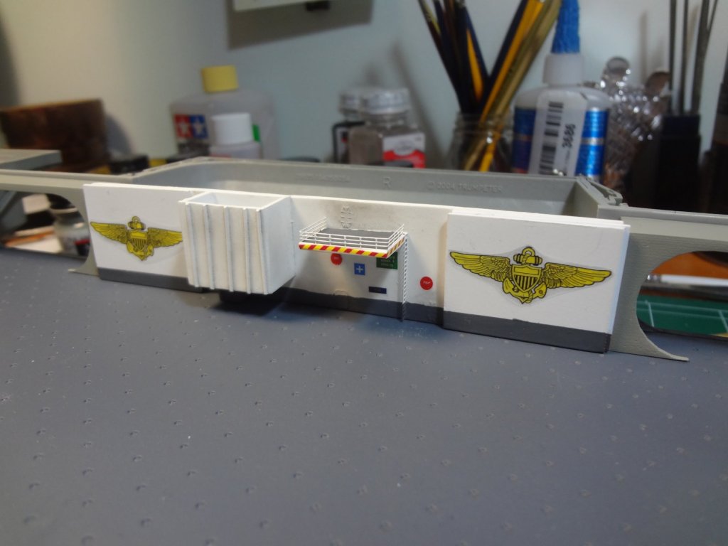
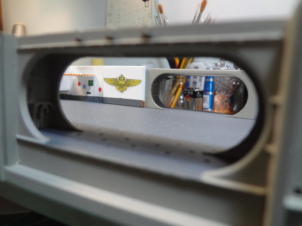
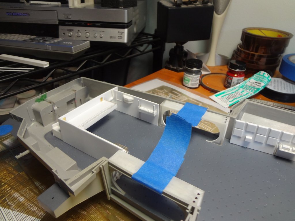
I could not locate decals to represent the many signs and logos for the hangar bay so I made my own. On the forward part of hangar bay 1 is an area that was used to repair the ground support equipment for the ship and the forward tunnel to various sections. I illuminated this area using 1mm fiber optics and a white LED.

- 82 replies
-
- 6
-
-
- carl vinson
- trumpeter
- (and 2 more)
-
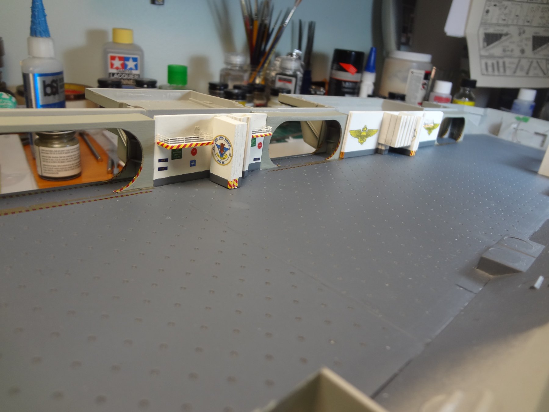
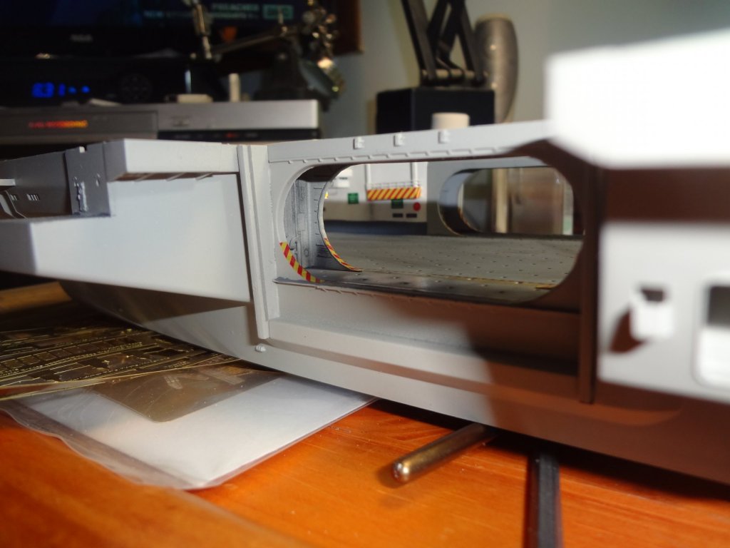
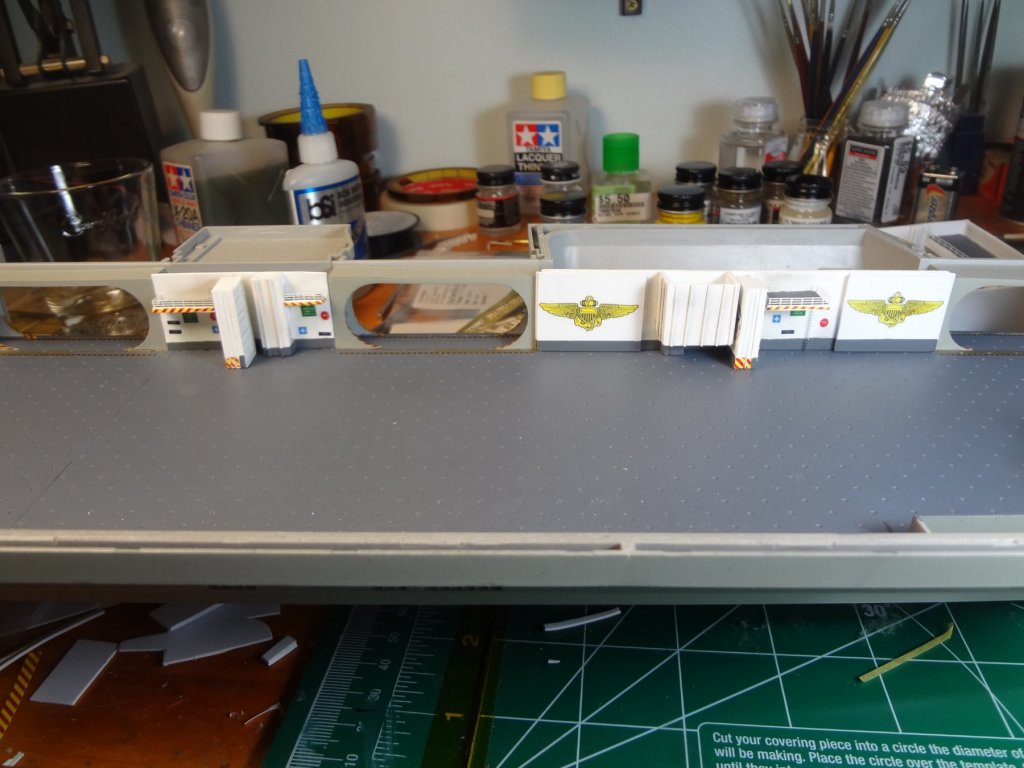
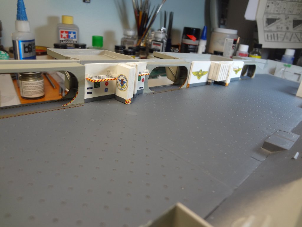
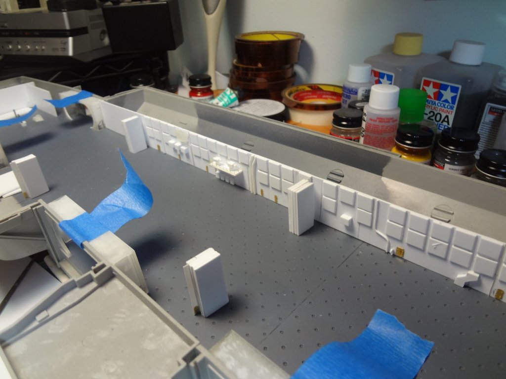
Next I started to build the hangar bay walls. I used Shapeways doorways and conflag stations.
- 82 replies
-
- 9
-
-
- carl vinson
- trumpeter
- (and 2 more)
-
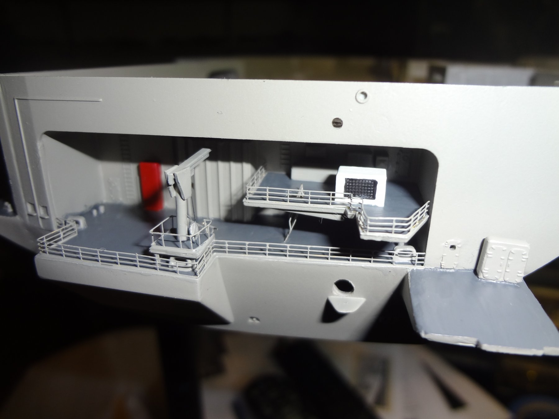
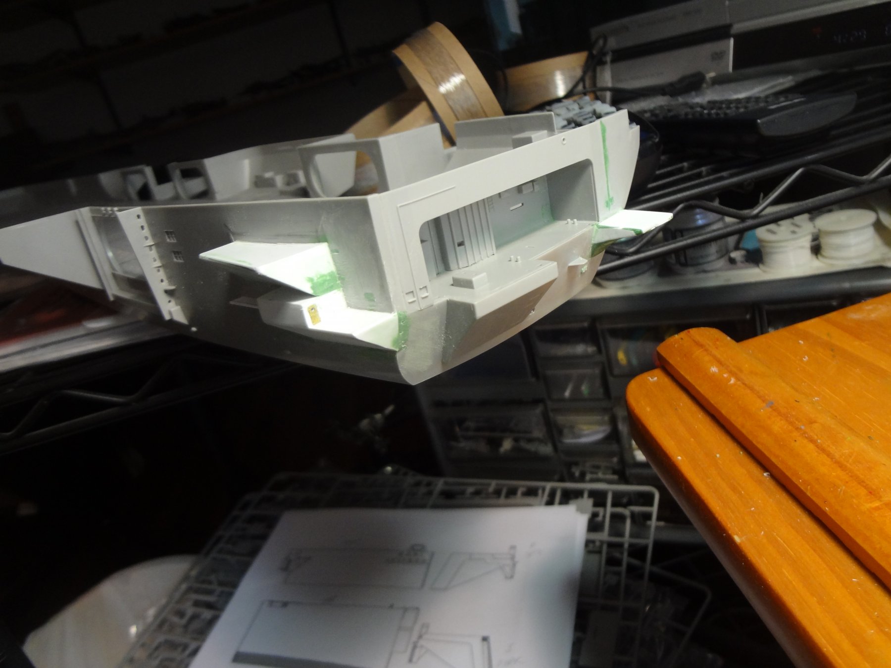
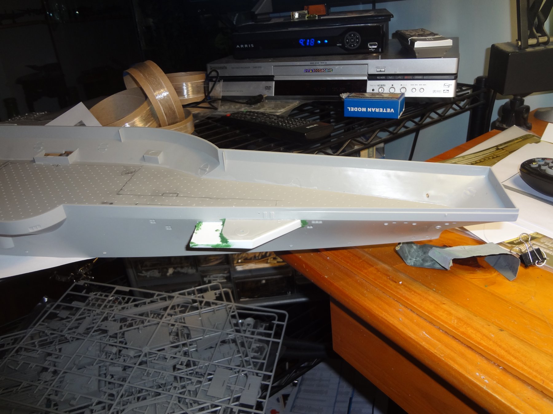
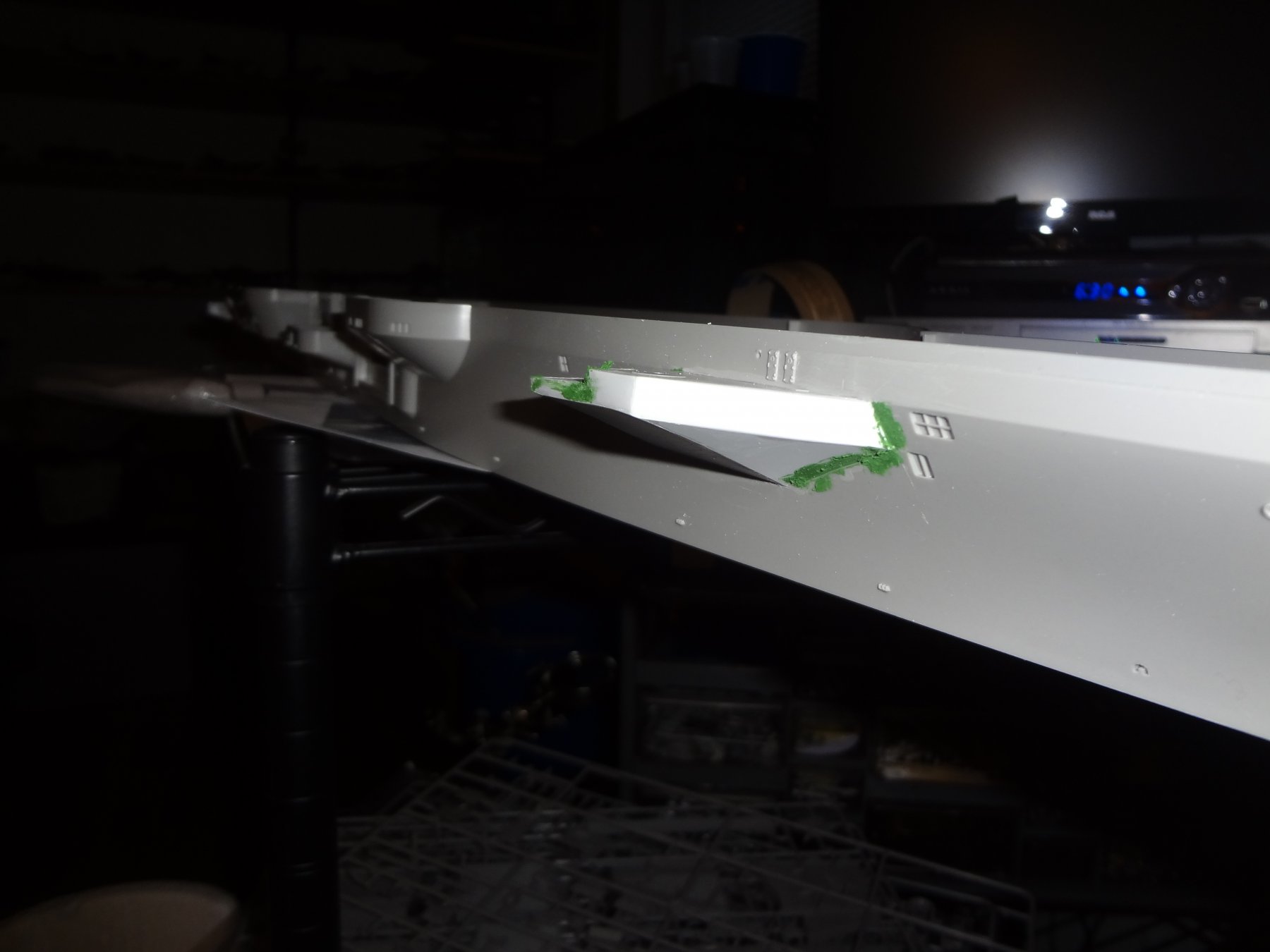
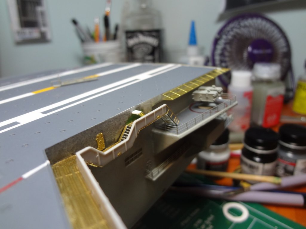
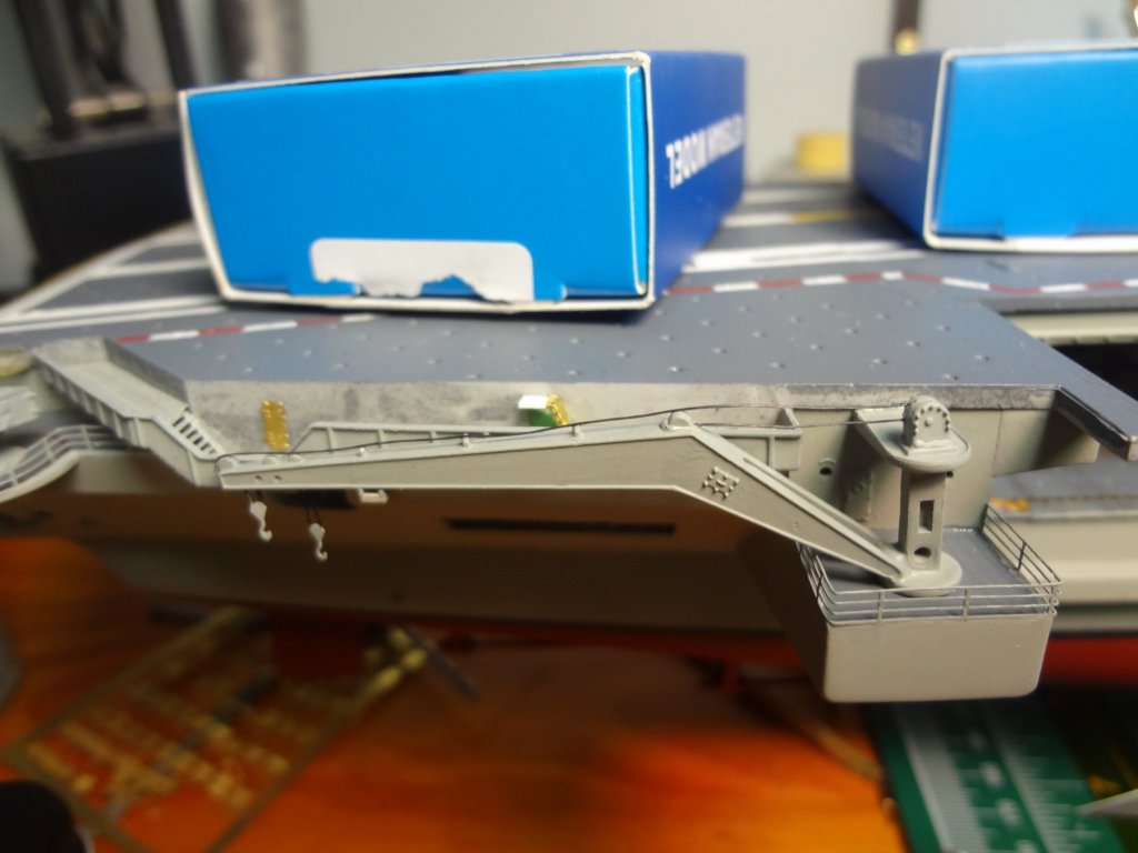
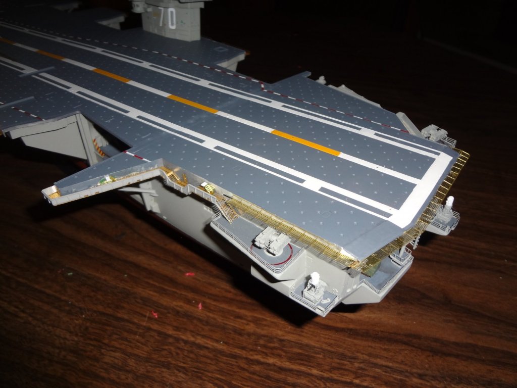
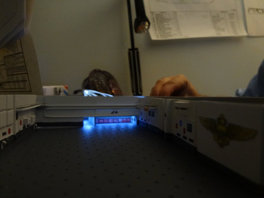
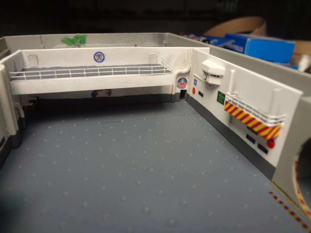
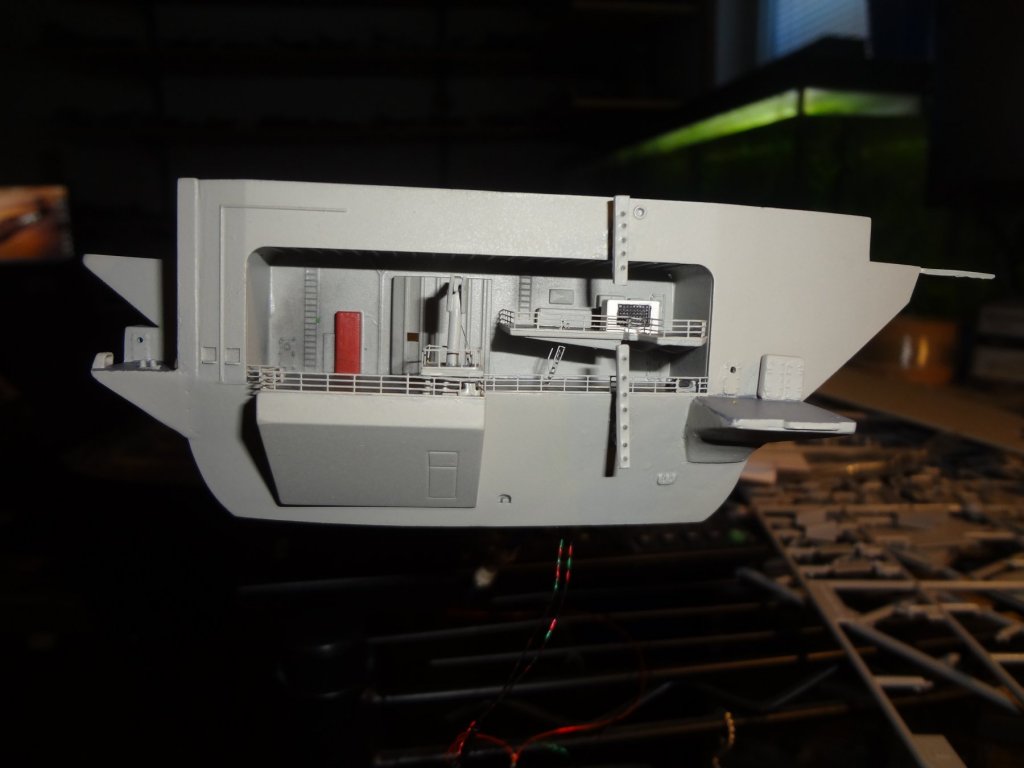
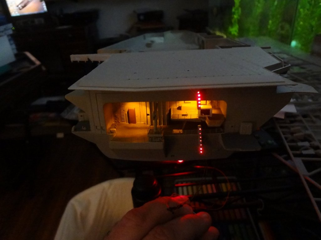
The fantail was modified to add the crane and other details. I used 2 pico sized LED's to illuminate the fantail sections and made the landing light sections using .5mm fiber optics which run to a 5mm red LED. The lighting of the ship is representing how it is lit up at night so the illumination of the fantail, sponsons and hanger bays will be using the yellow lighting.

- 82 replies
-
- 9
-
-
- carl vinson
- trumpeter
- (and 2 more)
-
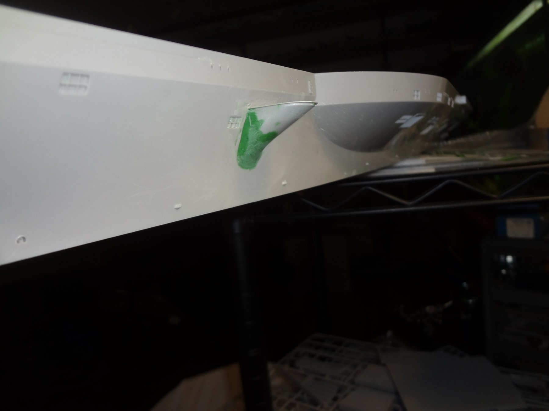
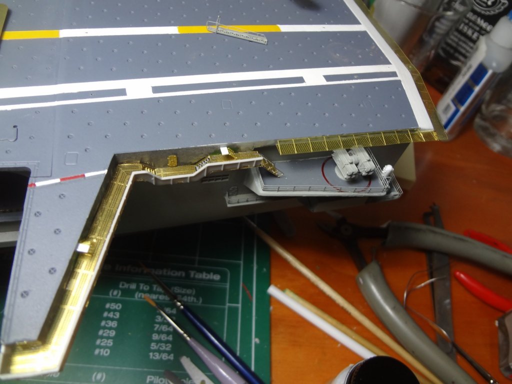
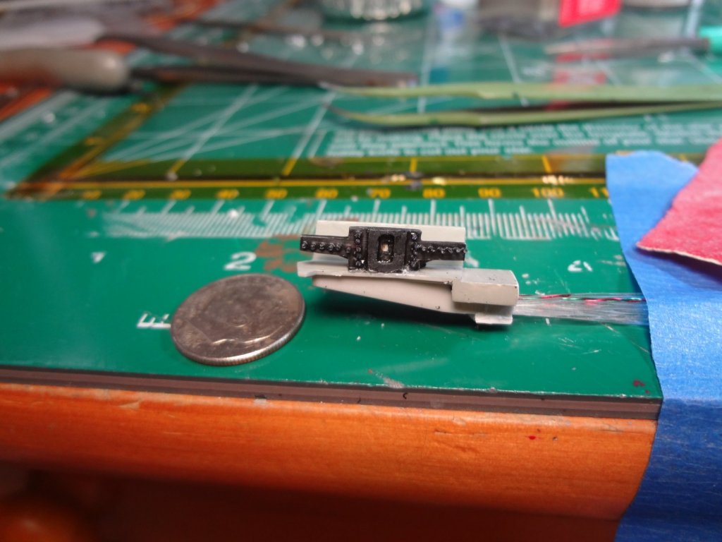
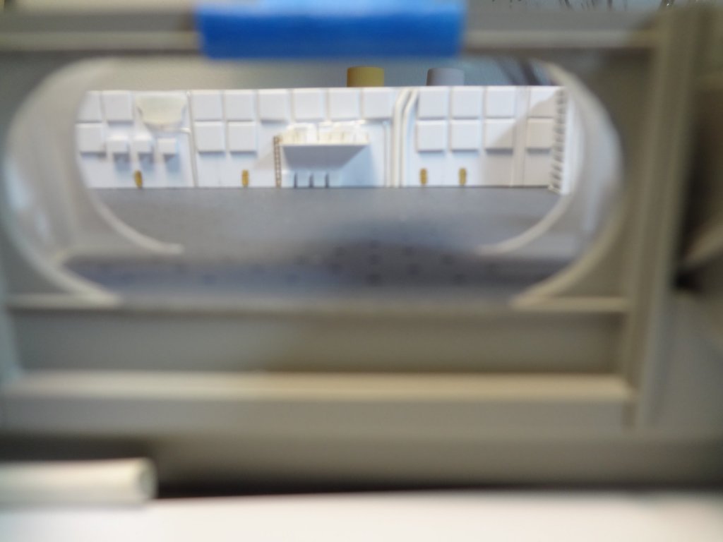
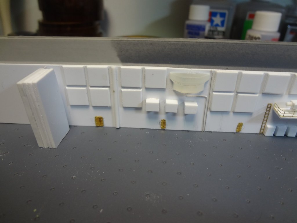
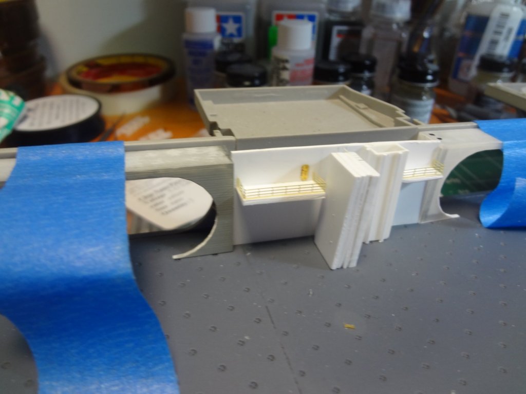
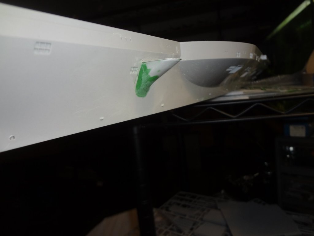
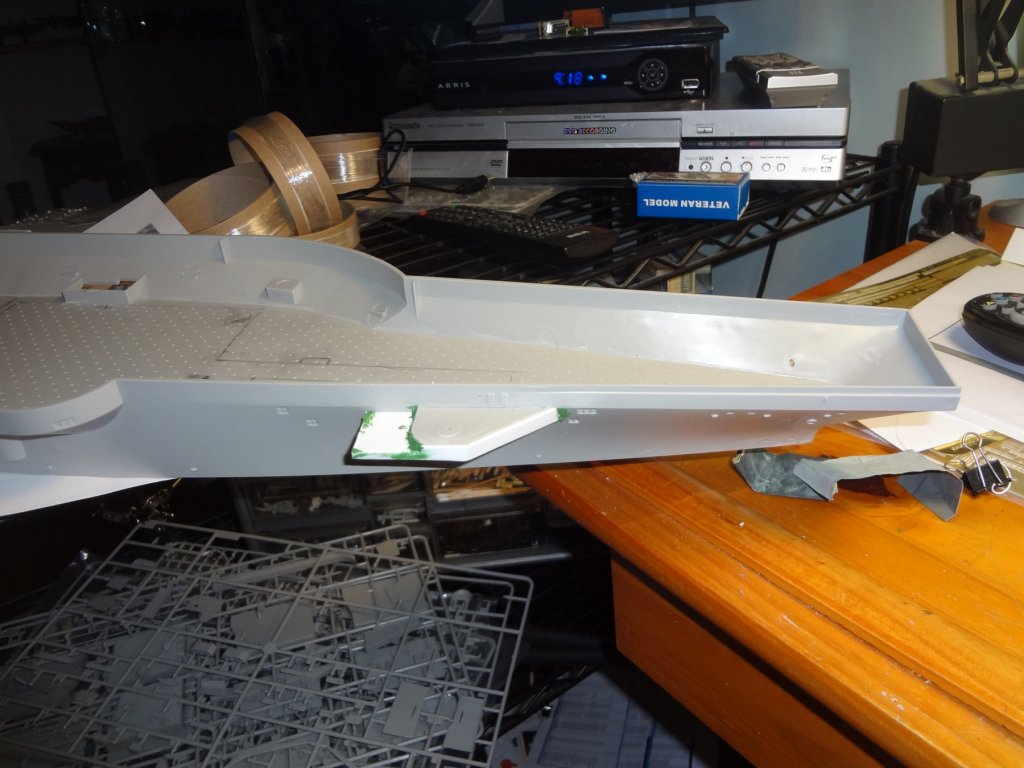
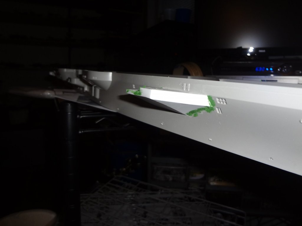
The first step was to replicate the Close In Weapons System (CWIS) sponsons. Using limited photo references I was able to get them scratch built and roughed in.

- 82 replies
-
- 8
-
-
- carl vinson
- trumpeter
- (and 2 more)