RobTBay
-
Posts
34 -
Joined
-
Last visited
Content Type
Profiles
Forums
Gallery
Events
Everything posted by RobTBay
-
 Thanks Chimp. I’m trying to do as clean a first layer as possible, partly just as practice for the more visible second layer. But you’re right, the first layer is about defining the shape of the hull …as long as you get there, it doesn’t completely matter how. 🙂Having said that, I’m still striving for using as little wood filler as possible. Mostly just to see if I can. I’m kind of thinking that the number or completeness of the filler bulkhead pieces may be less critical than just putting some kind of filler in the first and last two existing bulkhead sections. Some approaches might be better than others, but anything is better than nothing! Back to the workbench, and see what I come up with! Rob
 -
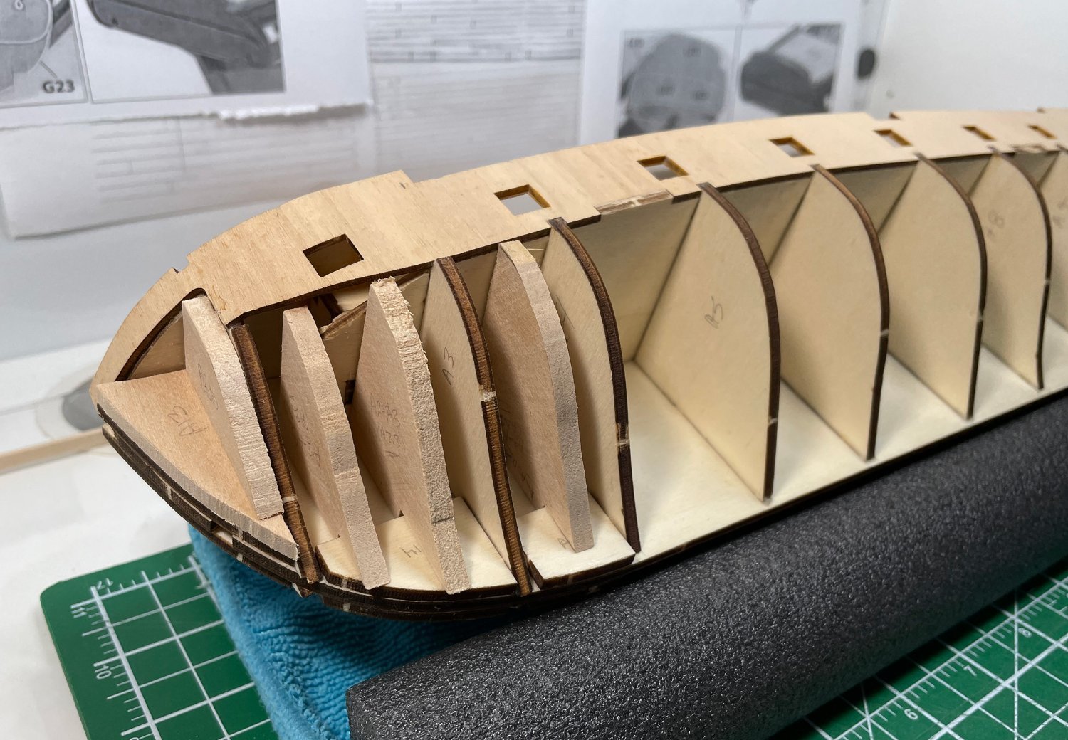
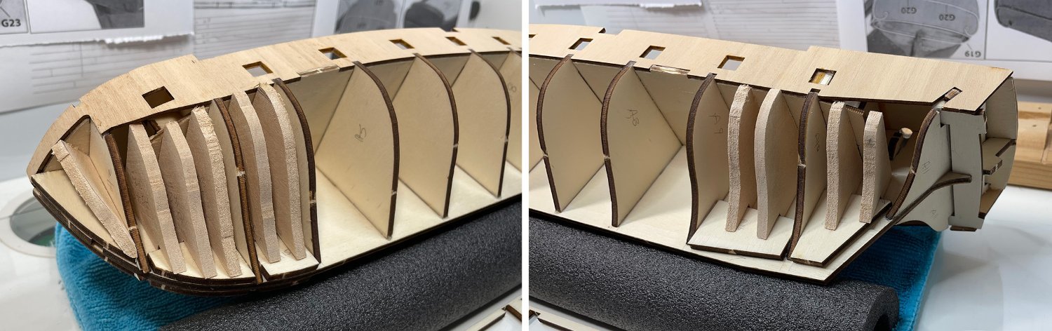
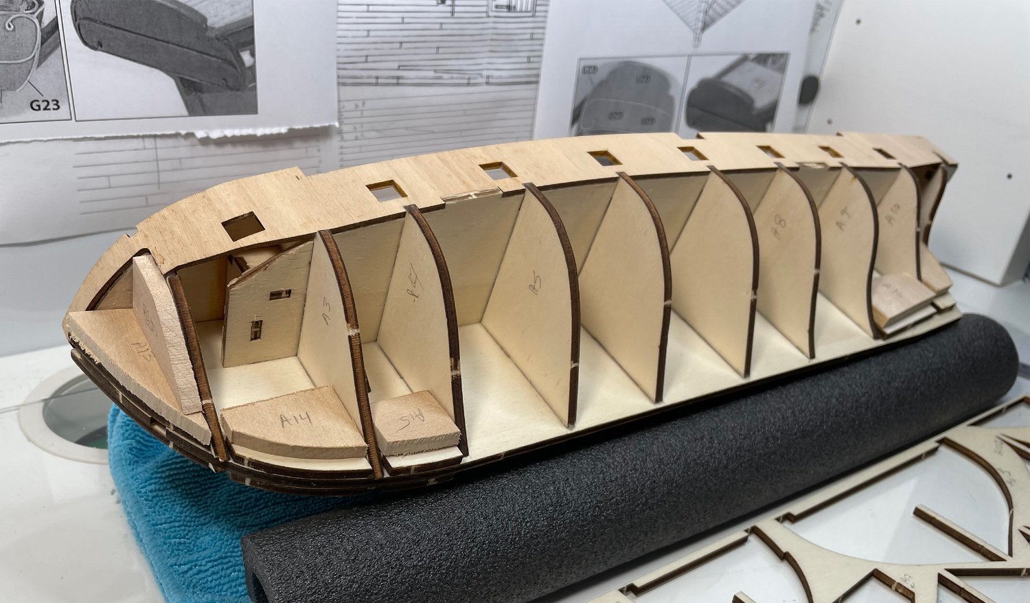
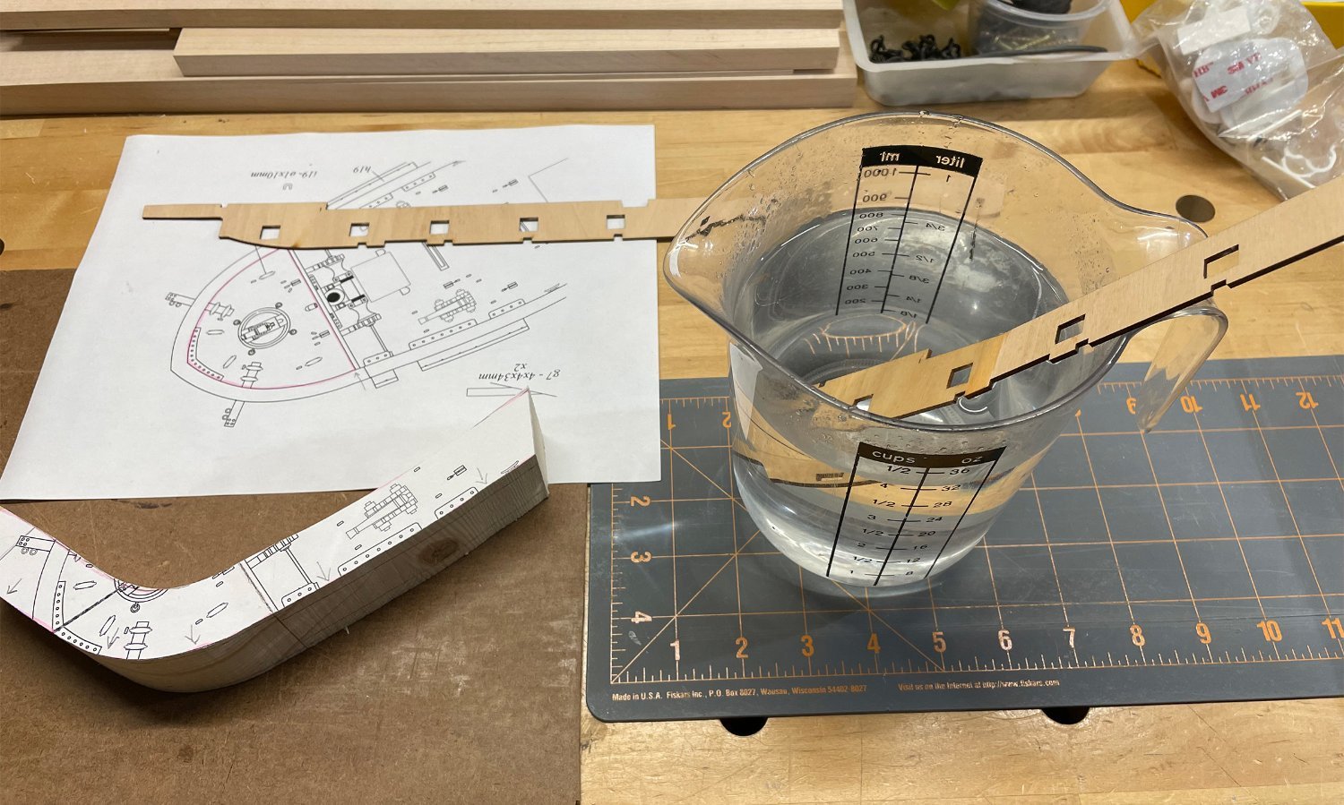
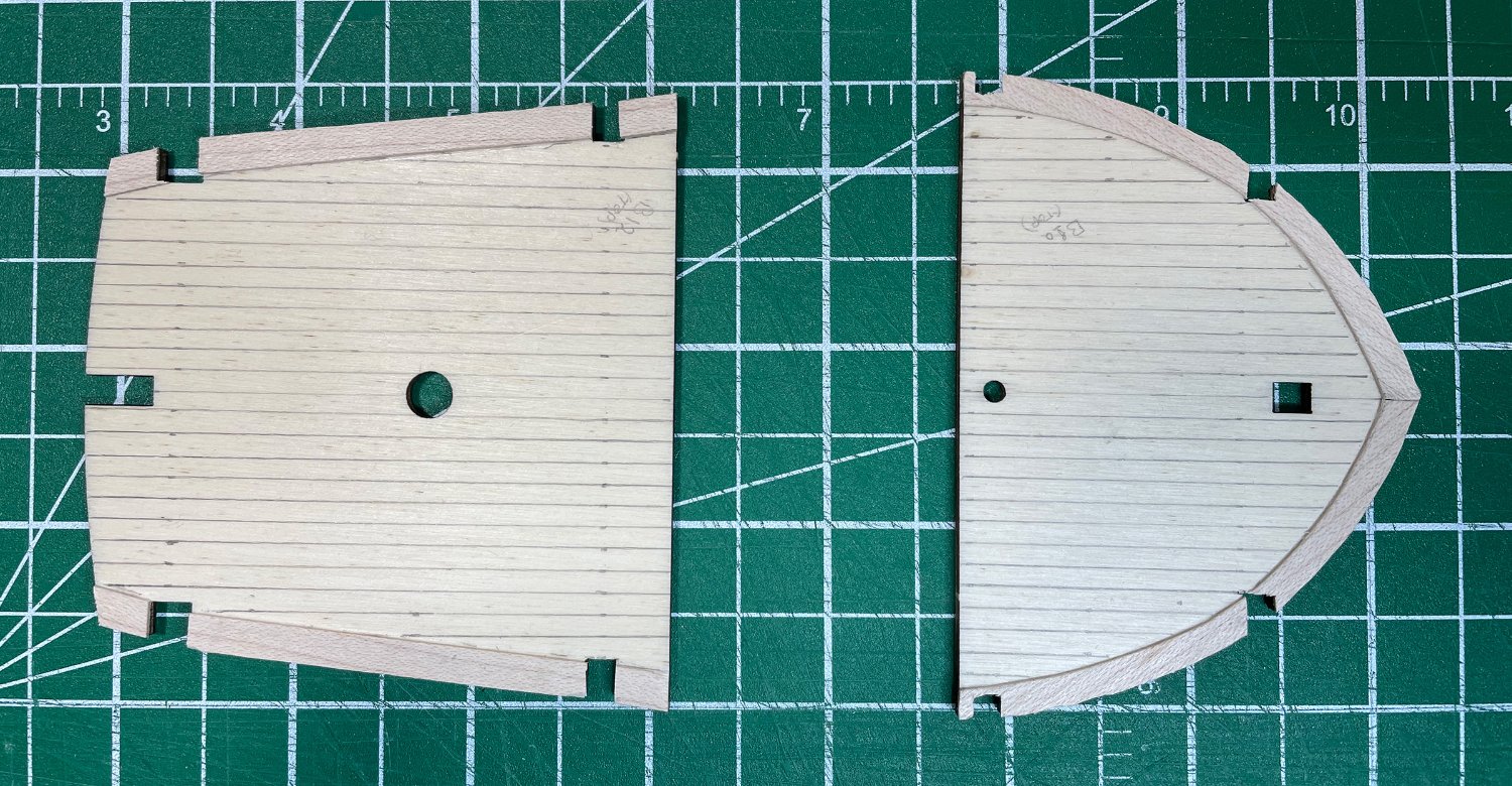
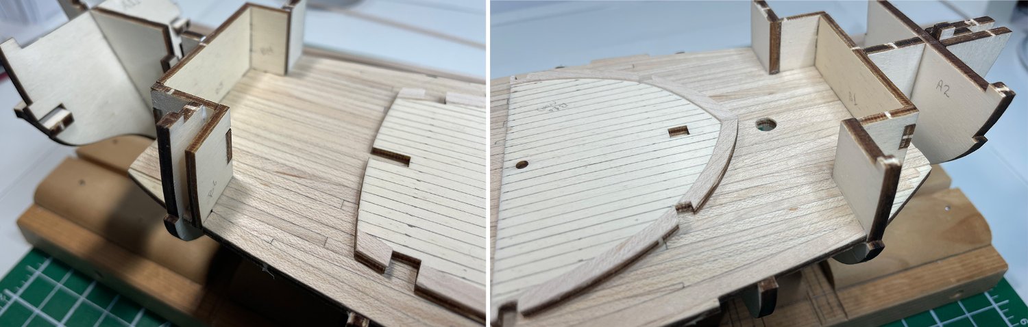
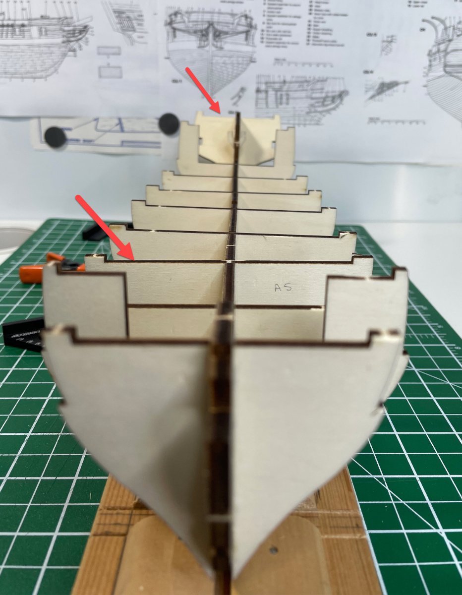
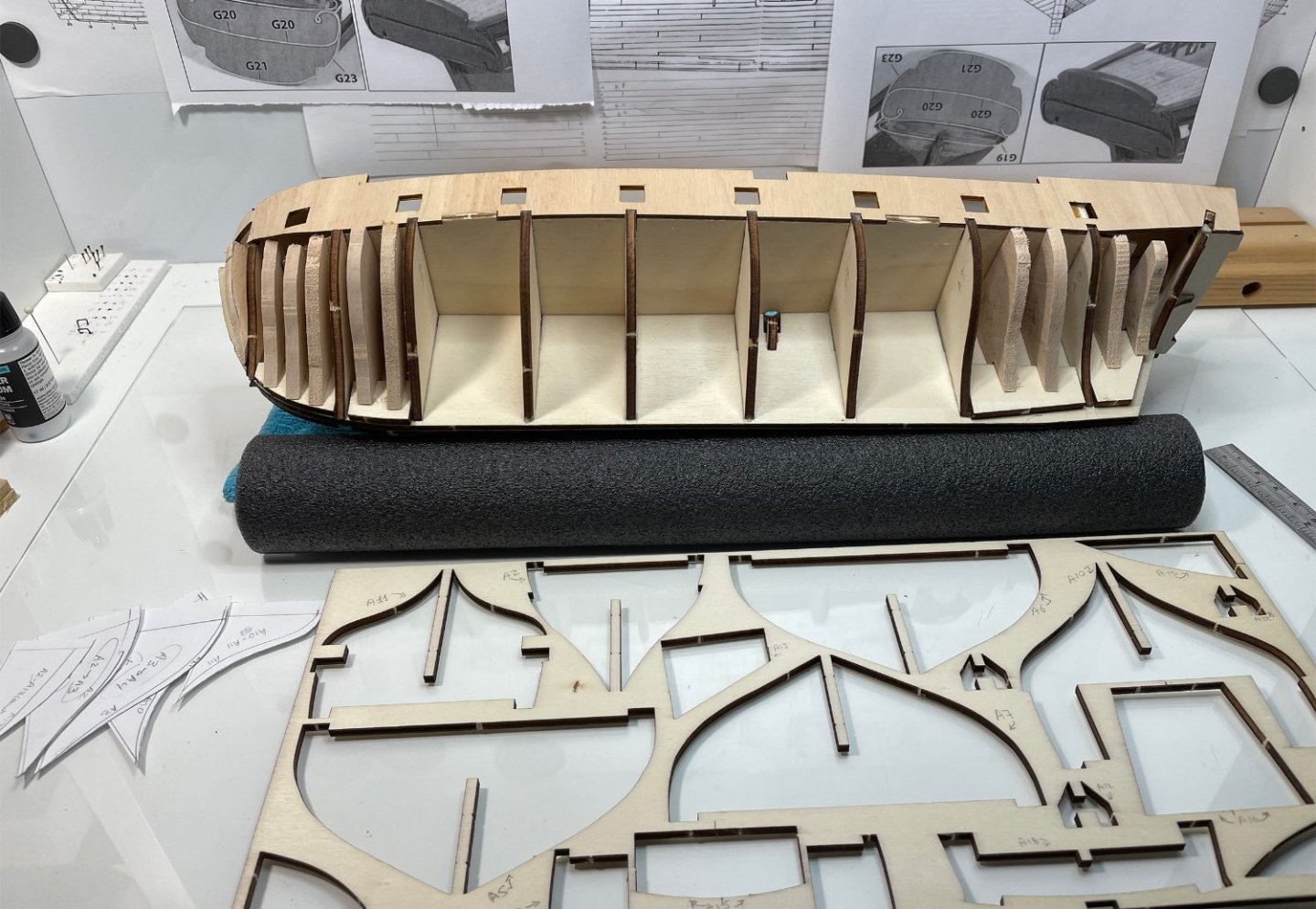
Preparing the hull for planking! And no, I didn't completely drop off the forum ...just had a busy summer. I did spend some of that time pondering how I'll be planking the hull, since I'm not planning on using the OcCre method. I should go back and review the planking videos and articles on the forum before really getting stuck in to the planking. On a few build logs (not necessarily just Beagle builds) I noticed that sometimes the bulkhead spacing near the bow and stern can cause the planks to bend at an odd angle as they cross over the bulkhead. So, I figure I'm going to need more support between the bulkheads to keep the planks running on a smooth flow. Of course, pre-bending the planks should also help with that a lot. But do I fill in the spaces with solid wood, or just add additional filler bulkheads? I'm thinking at the moment I like the idea of adding bulkheads. So, I built a few pieces to test fit the idea, see if I like the results. I took the remains of the parts sheet for the bulkheads and traced the outline of two subsequent bulkheads on top of each other, and then added some additional lines by eye to create in-between pieces. Since they will be sanded down anyway, as long as they are slightly oversized, the actual dimensions of each only needs to be close (absolute accuracy not essential). I'm only really concerned about the first and last couple of bulkhead spacings where most of the extreme bending will be occurring (and of course at the very bow as well). The rest I figure should not be a problem (I hope ). Here is an image of the pieces just test fitted, and then a closer view of the bow and stern. I still have a little bit of adjusting to do to the pieces, but that's the idea. However, I got to thinking that maybe I should thicken the shims at the bottoms, and on each edge of the bulkheads in the bow section as well? Which I think I will do. I'm also wondering if I need all those additional support bulkheads, perhaps where I had three, two would do, etc.? I may still add that angled bulkhead piece at the bow, or maybe just fill it in entirely. What do you all think, more or fewer ...or just go solid wood?? I'm thinking at the moment to add the additional shim pieces and go with one less additional bulkhead support in each section (at least at the bow end, the stern will probably still get two), more like the last picture above but with the additional shims added at the bottoms. Thoughts? Feels good to be back at the workbench! Rob


-
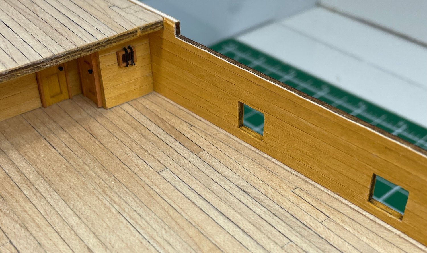
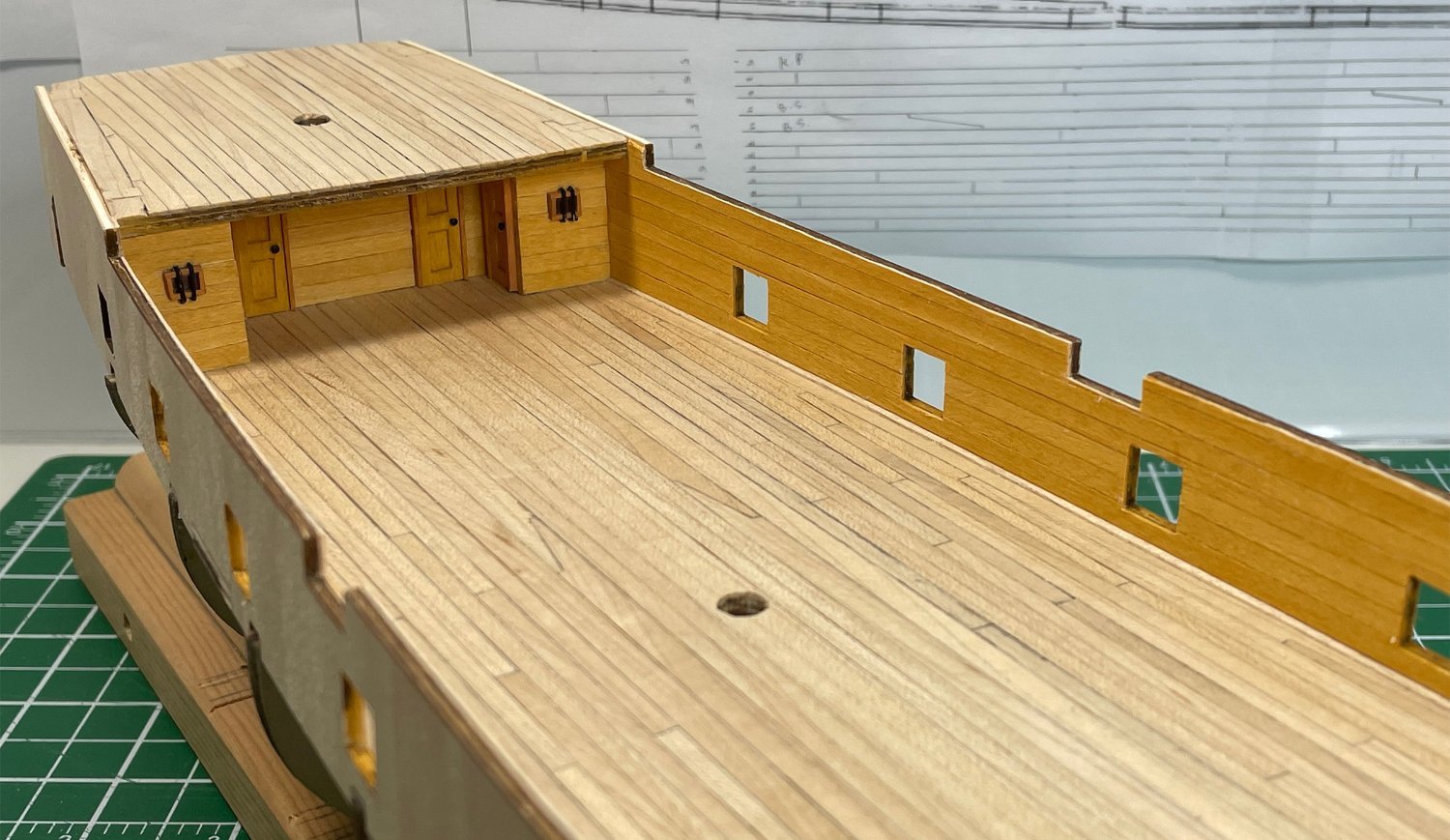
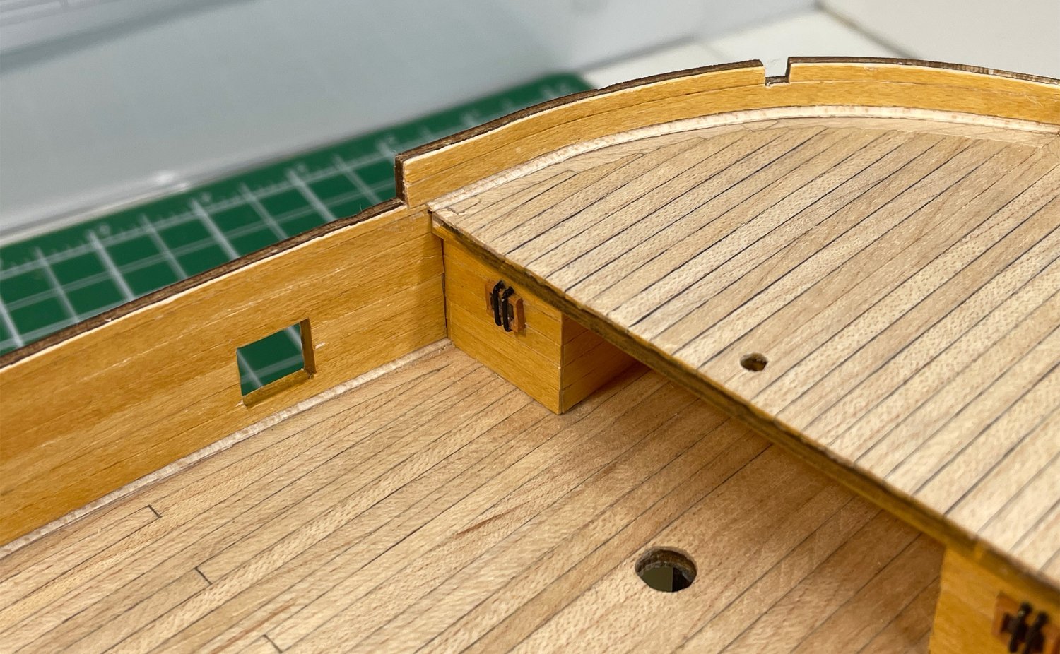
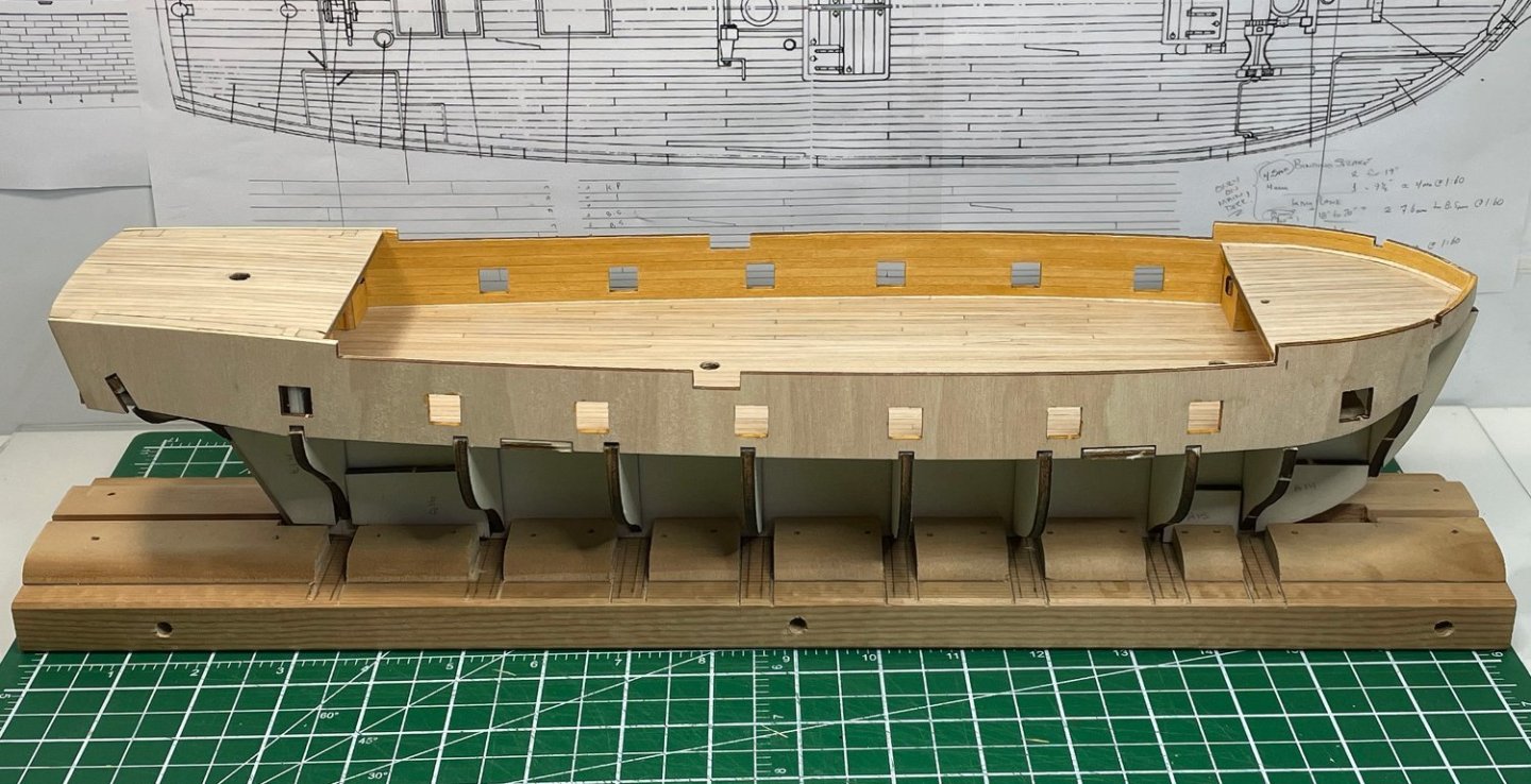
Bulwark interior planking complete! I went with thinner boards than provided in the kit, 3.5 mm width (to reflect Marquardt's drawings) rather than the provided 5.0 mm strips. I still used the provided sycamore strips, just cut them down. I wasn't worried about the bit of wastage since I had planked the deck with maple rather than the provided sycamore, so there was lots of sycamore strips remaining. I stained the planking with the same thinned down ochre brown I used for the forecastle and quarterdeck bulkheads. I noticed that in the instructions they never stain the plywood edges in the gunports. Some of that plywood is still exposed in the final assembly. I think the kit is relying on the sycamore and plywood being a similar colour and choosing not to complicate things. Me, I can't seem to resist complicating things! Also, since I stained the planking, leaving the plywood unstained would really stand out! So, I put a bit of the same thinned down ochre brown on the interior edges of the gunports. I'm guessing I will likely have to do a bit of touchup before I'm done, but at least they have been stained at least once while it's still easy to do. Here is an overview picture and a couple of close up shots of the bulwarks (and waterway detail)... I'm happy with the final look of the added waterway at the deck/bulwark join now that the bulwark planking is complete. It took a bit more work, but it adds that bit of detail and hides an obvious joint line. And here is one final picture of where the build is at so far... Now, on to prepping and planking the hull! As I work on sanding the frame bulkheads, I'll also be reading up on hull planking (and watching the videos) from the forum. I'm going to do my best to do it the "proper" way! Rob


-
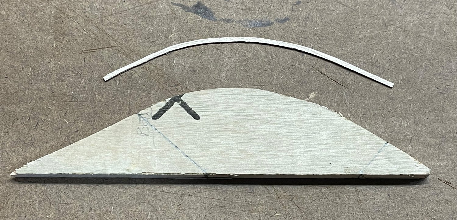
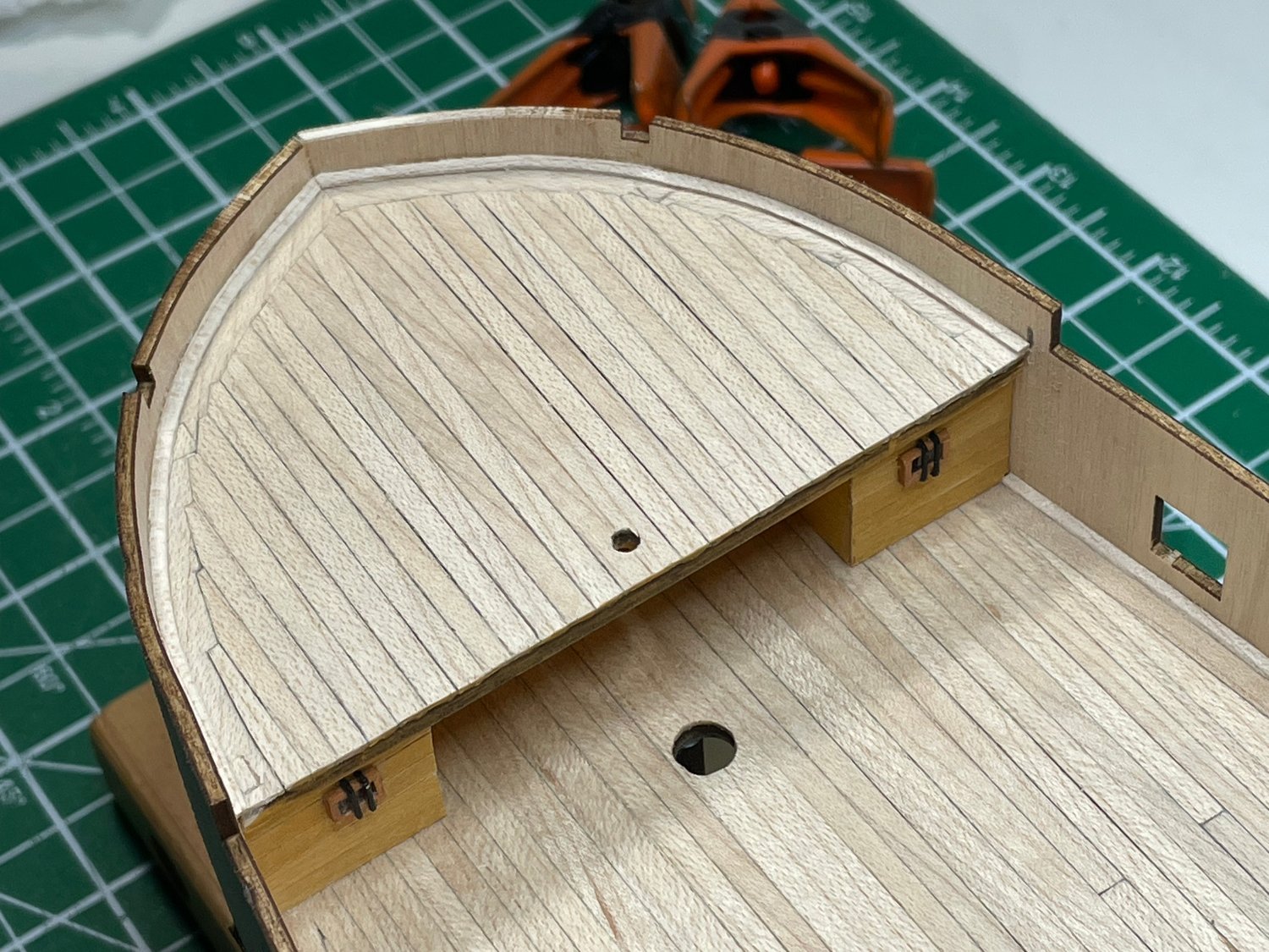
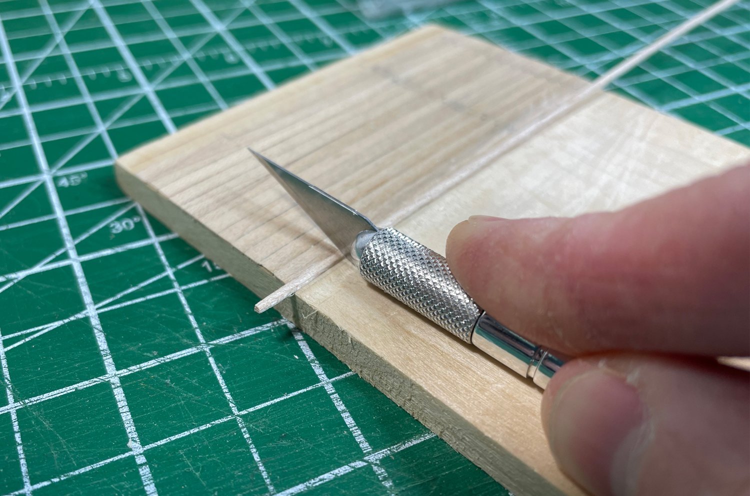
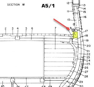
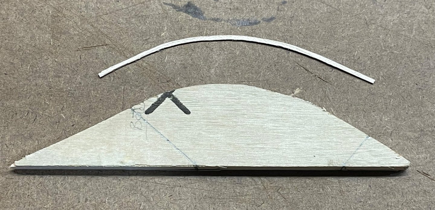
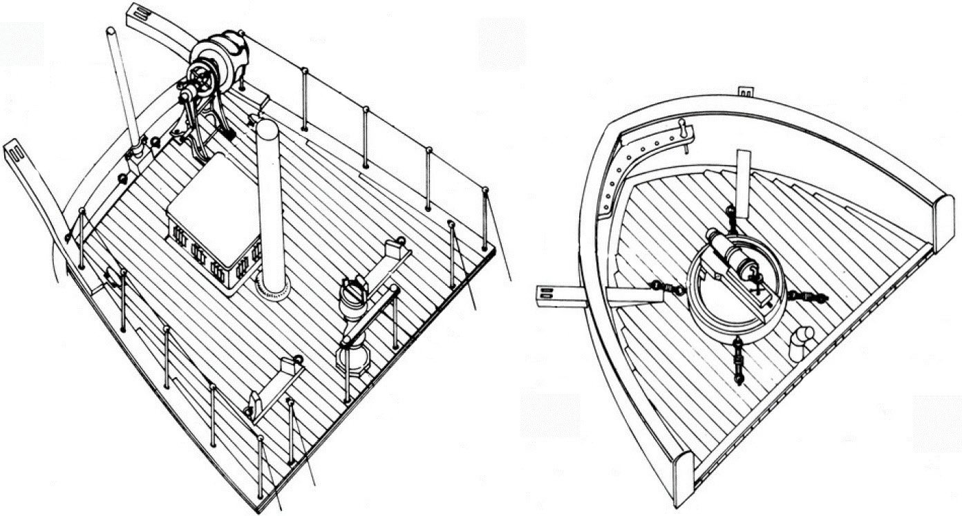
Adding the waterway along the join between the deck and the bulwark was on my wish list of things to add to the model. Not sure why this one got in my head, I just thought that it would be a nice detail that would add a touch of additional realism, which often didn't seem to be done ...maybe for a reason! From Marquardt's Anatomy of the Ship drawings (see below) the waterway would form the final deck plank (margin plank) or the base of the bulwark depending on how you look at it. I wasn't going to try and incorporate that additional profile height into the margin plank on the deck ...maybe someday when I'm up to doing scratch builds, but for this one I felt it was just a slight reach beyond my capabilities to pull off. Therefore, I was going to add it after the deck and bulwark planking was done. However, I got the idea that it would look better if it was installed before the bulwark planking, and then the bulwark planking could come down to meet it cleanly ...and hopefully make it look more like the integrated piece it's supposed to be, rather than added on at the end. I created a tiny 1.3 mm x 0.8 mm maple strip to match the deck planks. Then I used a #11 knife blade to scrape off the corner of the strip to make the profile almost triangular. I tried cutting off the corner along the strip, and then sanding off the corner, both of which left it a little rough without a nice straight edge. I eventually used the test piece I made way back when I was figuring out how I would do the deck planking. The test planking had been stuck on a piece of scrap plywood which provided a nice backstop which I could then hold the #11 blade perpendicular to and draw the strip through the gap. Then I just kept slowly moving the blade a little closer to the backstop and drawing the strip through until I achieve the desired profile. Installing the waterways along the main deck was no problem, since there was very little curve and the tiny piece bent laterally enough that it went in without even needing to be clamped. The pieces at the bow on the foredeck was another matter. They would have snapped if I tried to bend them laterally into place. So, I built another form just like I did for bending the bulwarks (just in 1/4" plywood this time). I then soaked the waterway piece to allow them the flexibility to be bent to the form and clamped it in place, using smaller clamps this time so that I didn't crush the tiny pieces. Once they were dried and set using the heat gun, it came off the form and held the lateral bend matching the form just nicely. I then flipped the form and did the waterway for the other side. Since they were formed to the bulwark shape, they installed without a hitch. I did use a couple of small clamps to make sure they didn't move while the glue dried, but they was no real stress on them to install. And here are a couple of pictures of the waterways installed. Once the bulwark planks are installed, the waterways won't appear quite as wide. I think that worked out pretty well! Now on to the bulwark planking. Rob


-
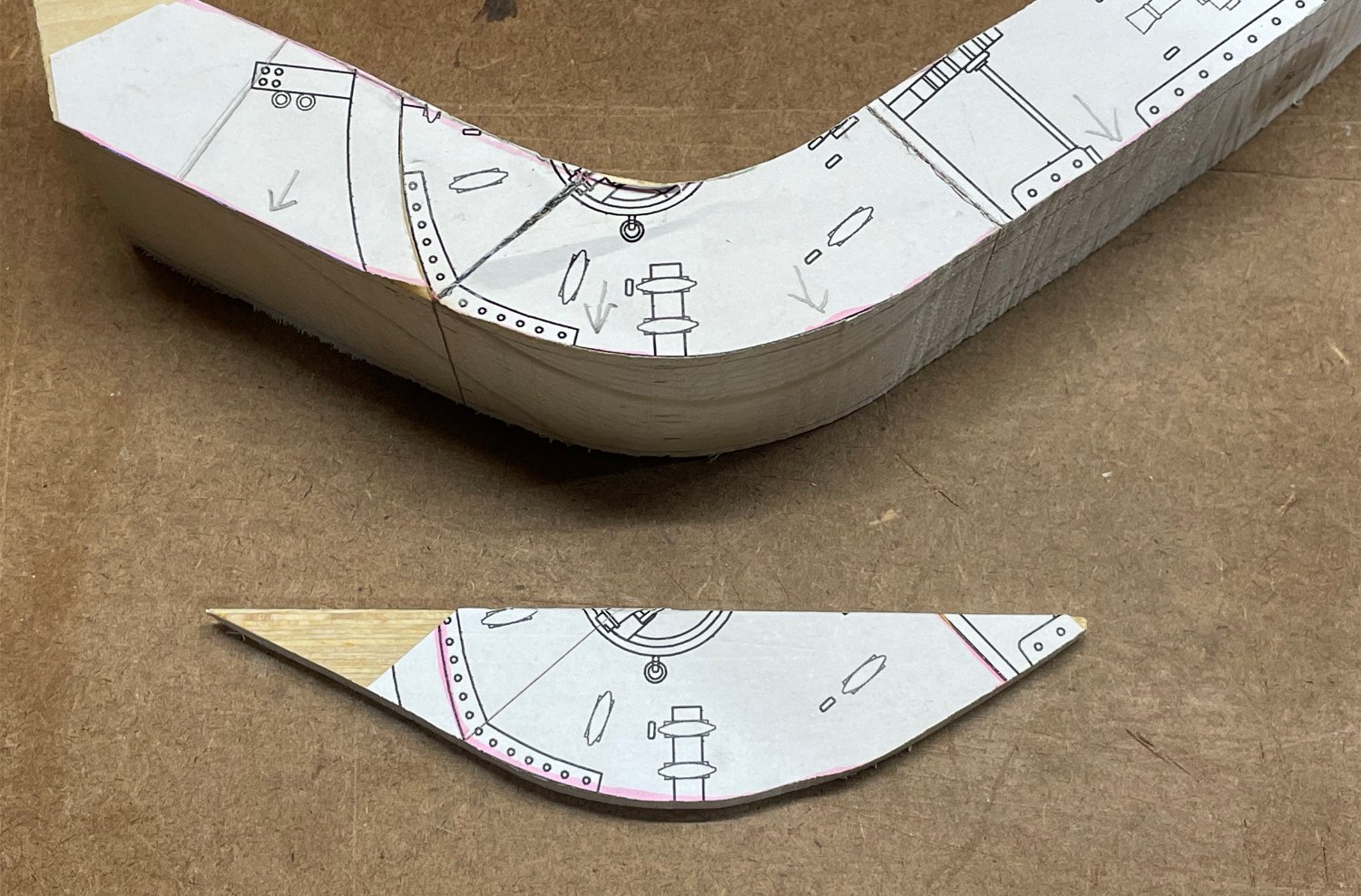
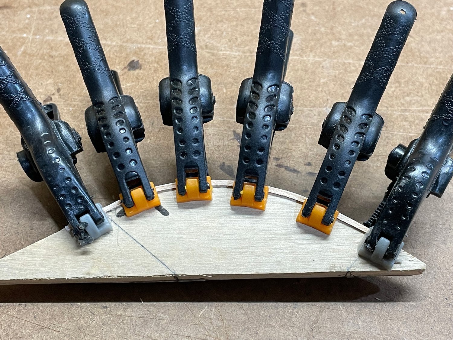
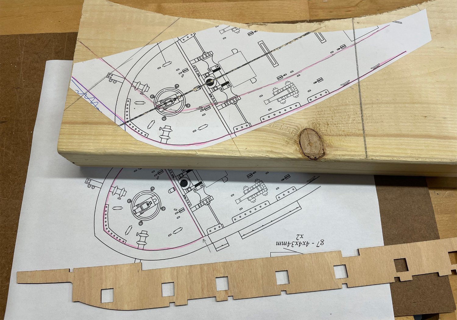
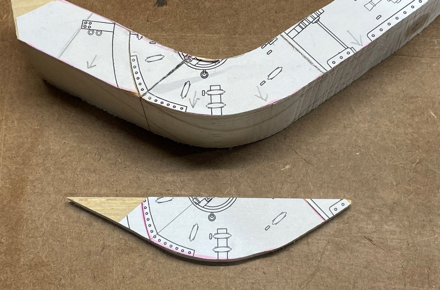
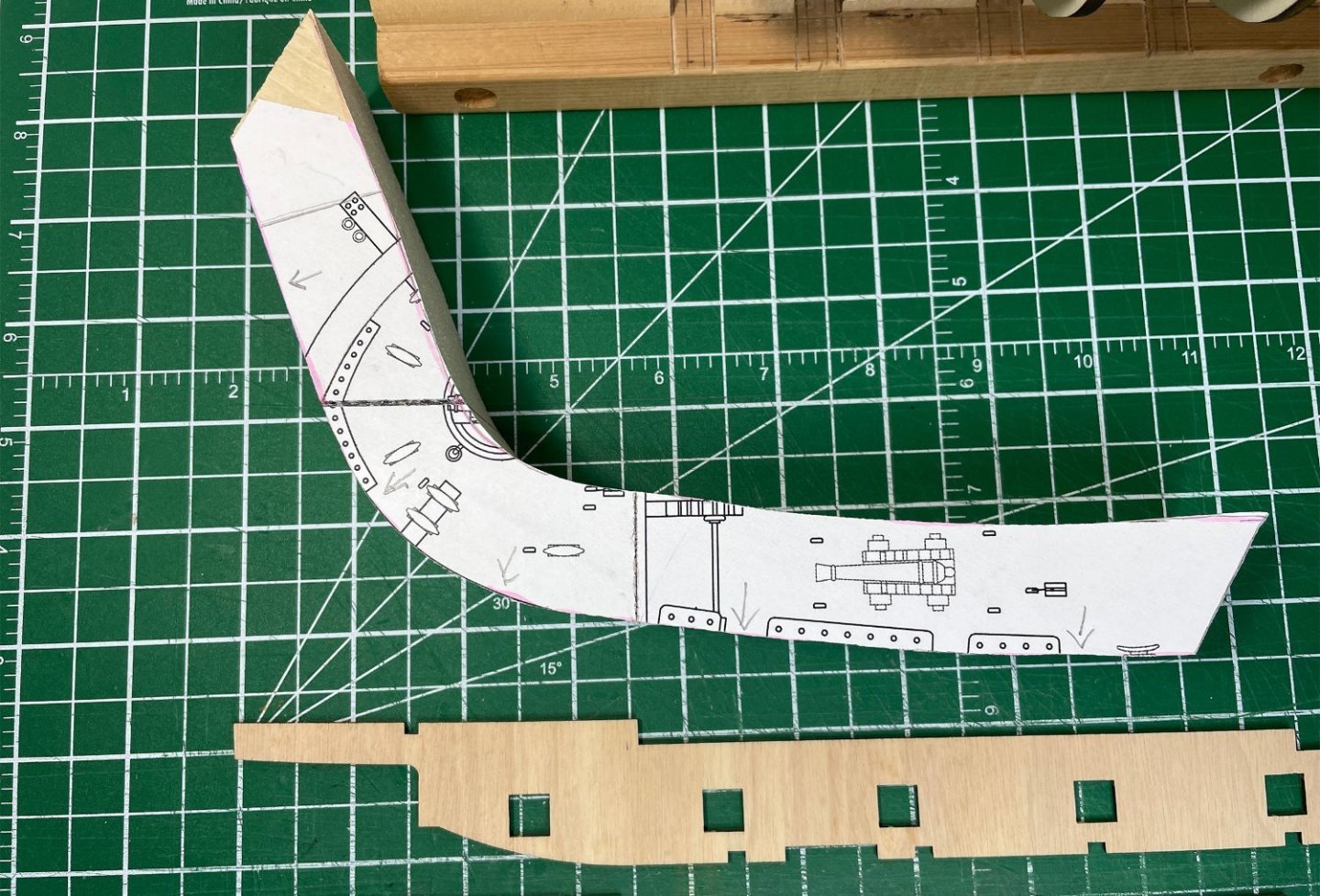
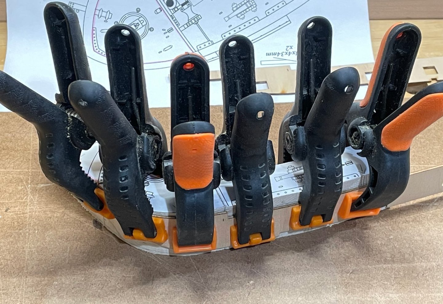
Forming and installing the bulwarks. The forward and aft couple of bulkhead frames required some sanding to make sure the shape of the bulwarks flowed nicely. This wasn't particularly hard, but I took my time and kept tweaking until I was satisfied. The instructions/vidoes showed using a can as a form to bend the bulwarks. Rather than trial and error bending around a single round form, I thought it would be better to have a form that was the correct shape for the bulwarks. I printed out a piece of the plans (at full plan scale) and pasted it onto a scrap piece of 2x6 pine. Then cut it out on the bandsaw along the line of the bulwark in the plan to make the form. I only really needed the form for the bow portion of the bulwarks, since the rest has very little curve to it and was easy to bend into place without any straining. Then came the soaking of the plywood part. This step made me a little bit nervous. Getting plywood wet is generally considered the way to delaminate plywood! However, the instructions called for a 20 minute soak, which is what people seem to do successfully in their build logs. Trying to bend the dry plywood to the form would very likely have caused it to crack, it needs the wood to be softened up a little to take the bend. So, soak it I did. I only put the bow section of the bulwark in the water, since that is the only part I was going to bend on the form. Then I generously clamped it to the form and used a heat gun to dry it back out again and set the new shape while still clamped. Once I completed the first bulwark, I flipped the pine form and did the second bulwarks with the curve in the opposite direction. I wish I had thought to take a picture of the bulwark once it came off the form, it kept the shape perfectly. Which means it took very little clamping pressure to install the bulwarks on the ship. I just used modified binder clips to hold it in place at each bulkhead and a little bit of painters tape to ensure it stayed exactly where I wanted it. And a picture of the two bulwarks installed... I was dreading this step a bit. But in the end, it went smoothly, and I didn't encounter any problems. Next step is to decide whether I'm going to add a waterway detail or not along the deck/bulwark joint first, or just move straight to planking the inside of the bulwarks as in the instructions? Rob


-
Thanks @RossR! Those doors and windows took a bit to trial and complete ...I'm glad I'm not the only one that thinks they were worth the effort! Rob
-
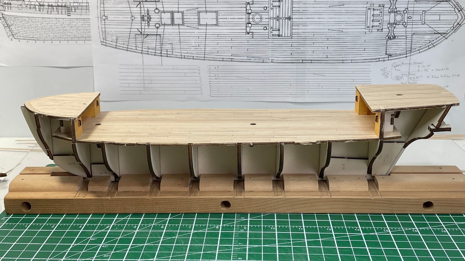
Deck planking on the forecastle and quarterdeck is now complete and the decks installed. It went fairly well, complete with joggling the deck planks where they meet the margin boards. I went for the correct impression more than precisely accurate for prototype construction. It's close and gives a good impression of what is shown in the Marquardt's Anatomy of the Ship. I'm happy. If anyone recalls a comment from @Whitebeard a while back reminding me to not cut out the reference holes that show in the plywood subdeck when installing the deck planks. I think my answer was something like "sounds like something I might do, but I'm fully aware and watching out for that!". I guess I have to eat my words. One evening I had a few minutes to spare, and I sat down and trimmed up the margin boards I had installed ...and cut out the matching reference holes! I didn't notice what I had done until I had finished the quarterdeck planking and was half done with the forecastle deck planking. I filled in the holes with some 1.0 mm maple (thick enough to fill the space but not interfere with the reference tabs from the frames). The quarterdeck margin boards will be covered by another piece anyway, only a little bit will show. The forecastle repair will show a little more, but it's only in the margin board and there will likely be enough busy stuff going on the deck to distract from it. I don't think it will show much in the end. Oh well, it could have been a bigger error, and not hard to recover from. Here are the two decks installed... And I'll leave you with a picture of the current state of the build... That catches you up for the last couple weeks of work. The doors and windows took some "trial and error" effort to come up with something I was happy with, but I think it was worth the effort. Next, it's on to the installation of the bulwarks. Rob


-
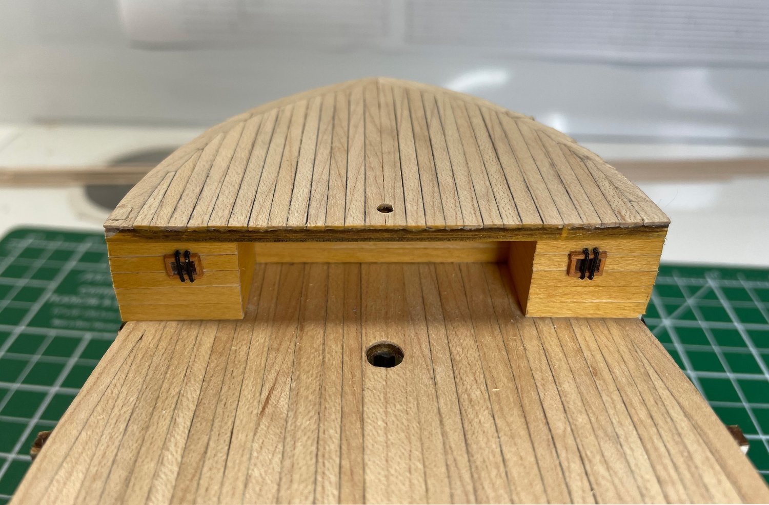
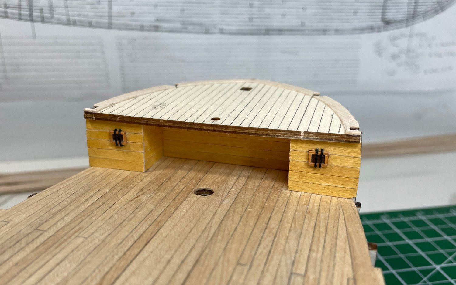
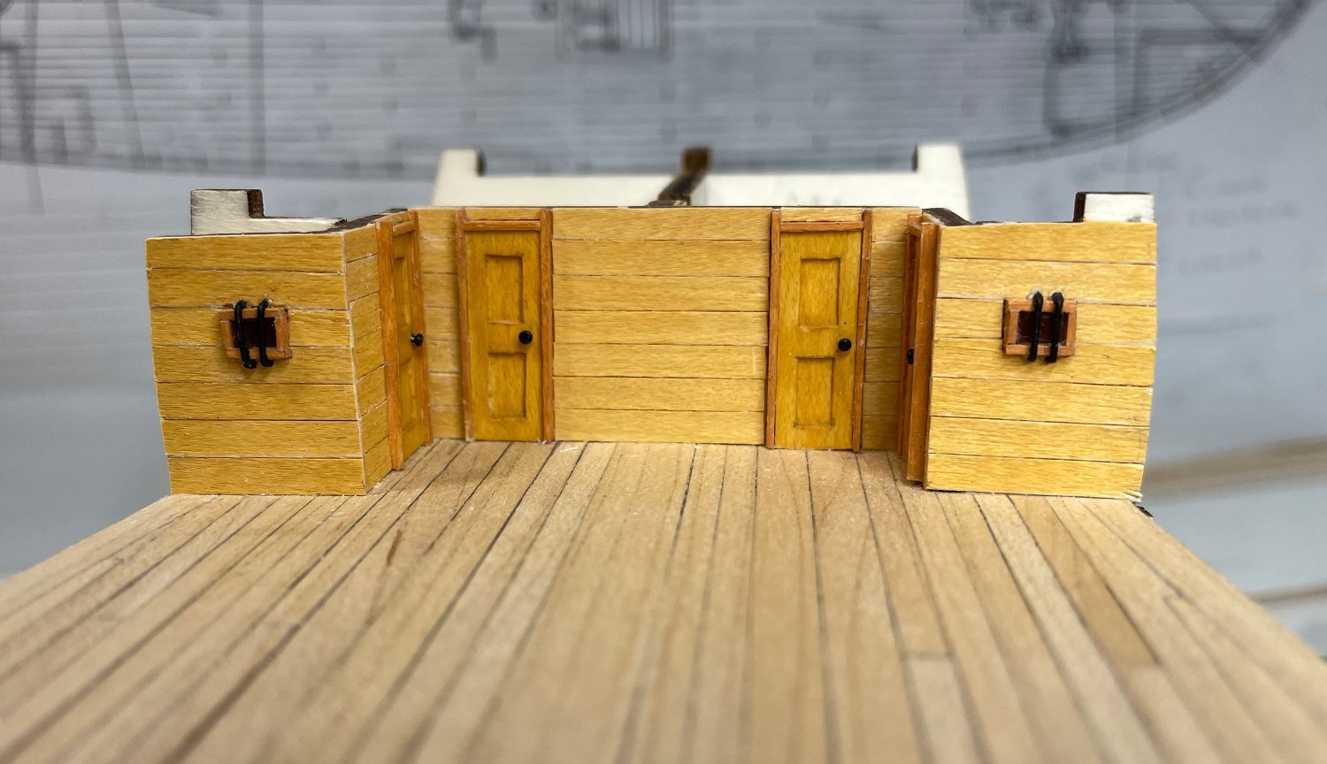
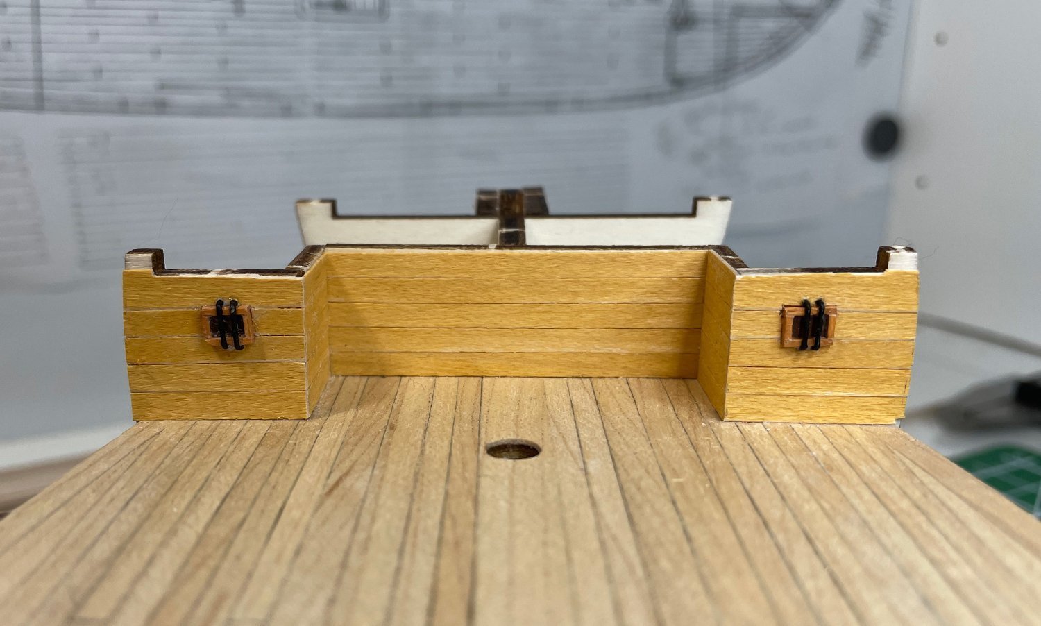
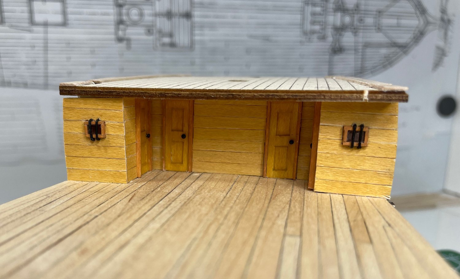
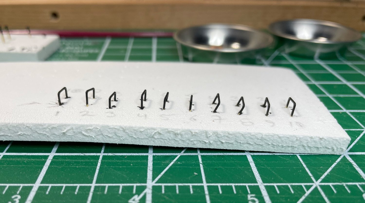
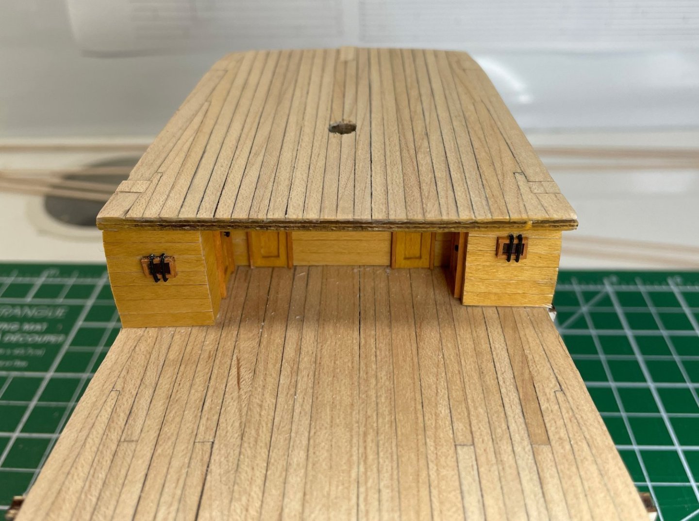
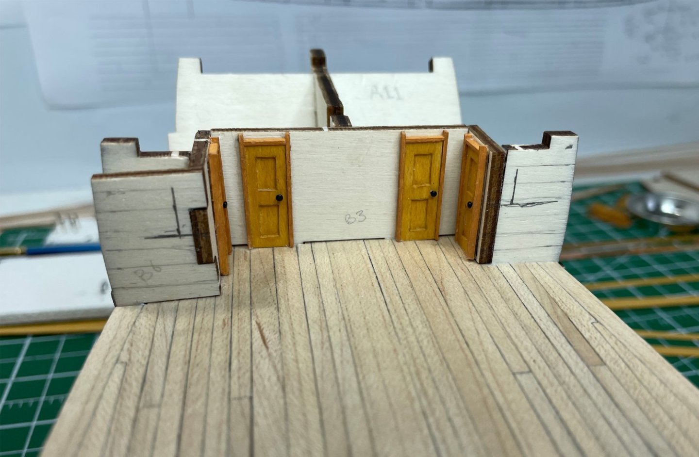
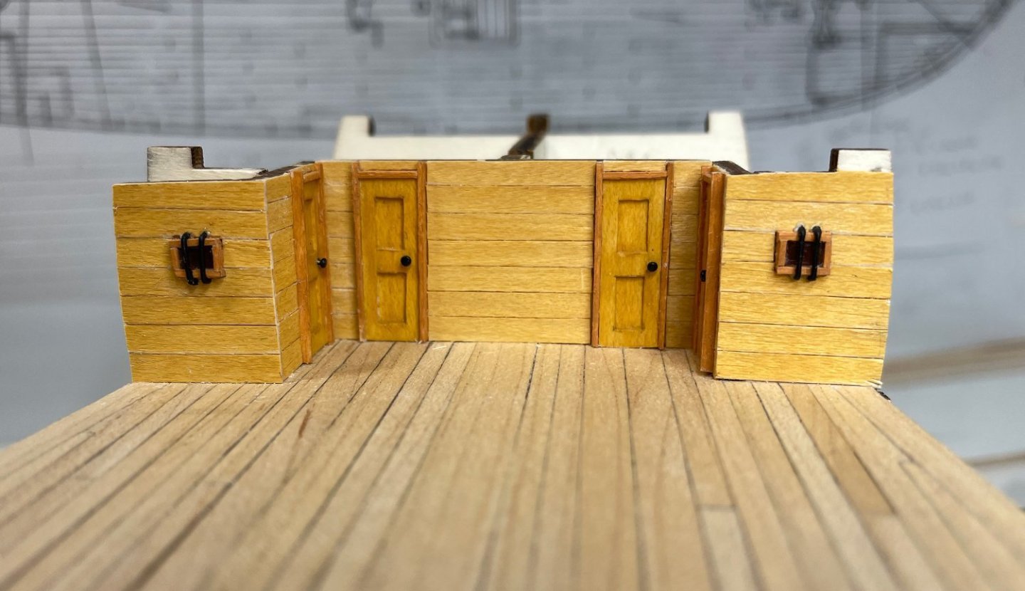
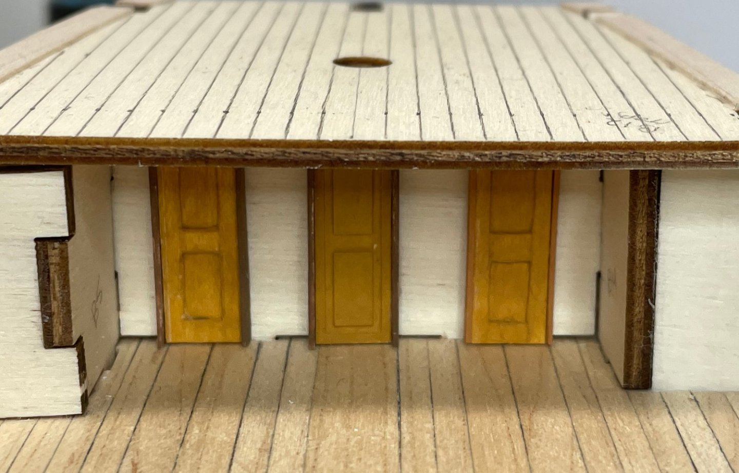
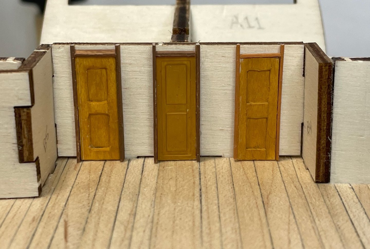
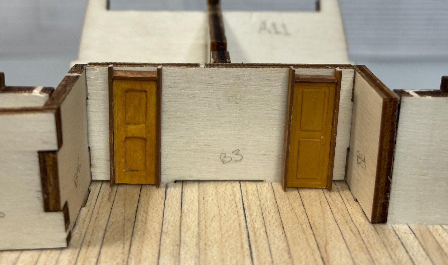
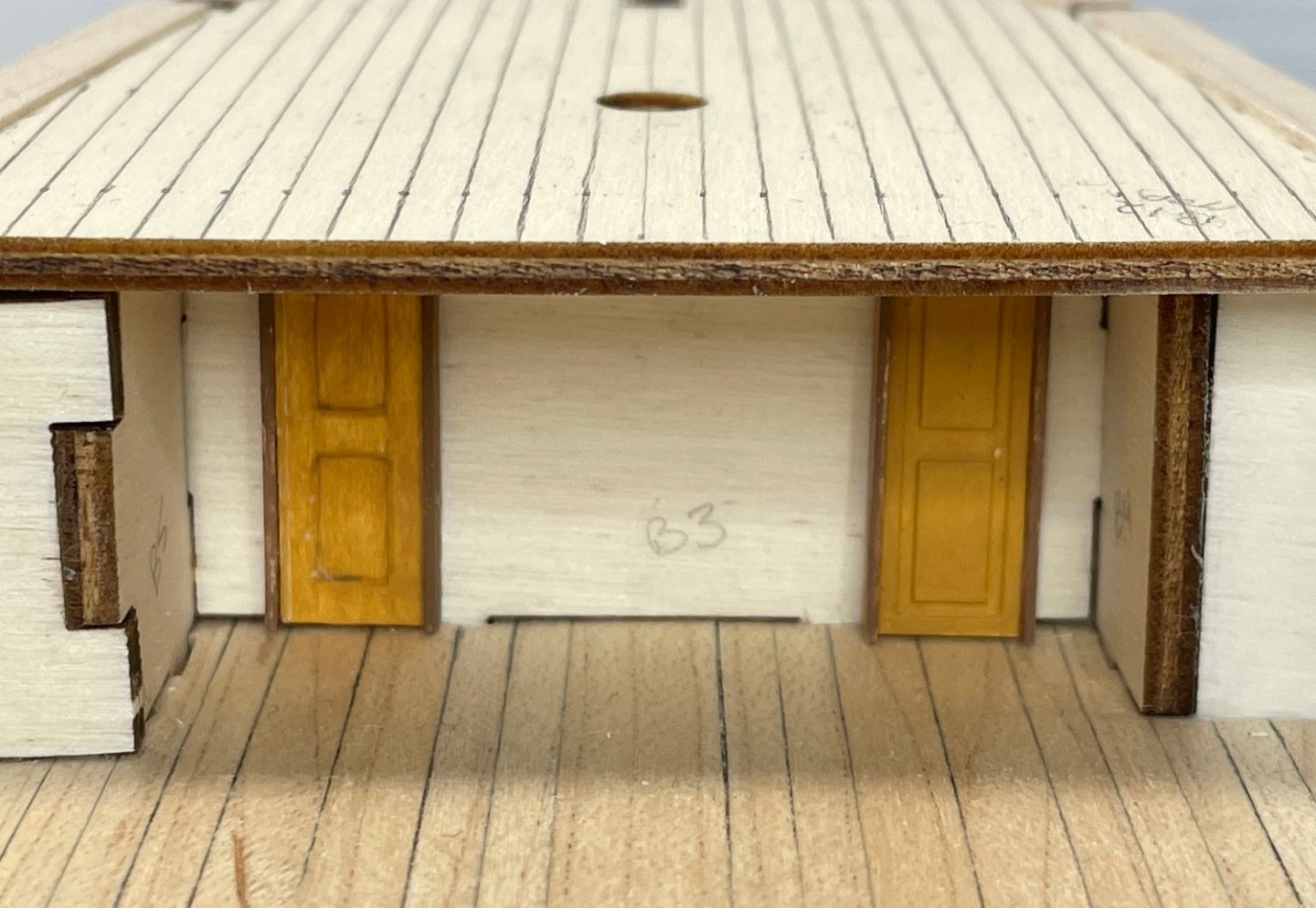
The bulkeads under the quarterdeck and forecastle have now been completed, complete with doors and windows. First off, the doors were installed. I added the doors and windows before adding the planking. As much as possible, I wanted the doors to have the impression that they were in the walls, not on top of the walls ...so I took advantage of every little bit of depth I could get, short of cutting holes in the bulkeads for the doors and windows! I also passed on the etched brass windows in the kit and made some simple rectangles from 0.5 mm maple stock, that surrounded a piece of acetate glued to some maple painted dark brown. I experimented with trying to attach the acetate to the frame only, but the whole structure was too delicate (the thickest piece only being 0.5 mm thick!). After a number of different attempts, I went with simply gluing the acetate to the painted backing board. The glue dries not completely clear, but it gives the window a kind of old imperfect window look ...which I think is actually kind of fitting in the end. At least that's what I keep telling myself. I took some 0.51 mm (0.02") brass rod and bent a set of safety bars to put over the windows (painted black). I experimented with several different ways of depicting and attaching the safety bars and went with the bars bent over the outer frame of the window. After attaching the doors and windows, I added the planks to the bulkheads. The plank widths were cut down to 3.5 mm from the 5.0 mm sycamore stock provided in the kit. This gives approximately the size as to what is shown in Marquardt's Anatomy of the Ship. I stained the planks a thinned ochre brown to match the doors. The door frames were stained a slightly different light brown color to provide a bit of visual contrast. This should give a nice but subtle contrast between the bulkhead planks, the deck, and eventually the sapelli highlight color. And here are a couple of pictures with the sub-decks for the forecastle and quarter decks temporarily put in place to give an idea of the final effect. Now it's on to finishing the planking of the forecastle and quarterdecks. Rob


-
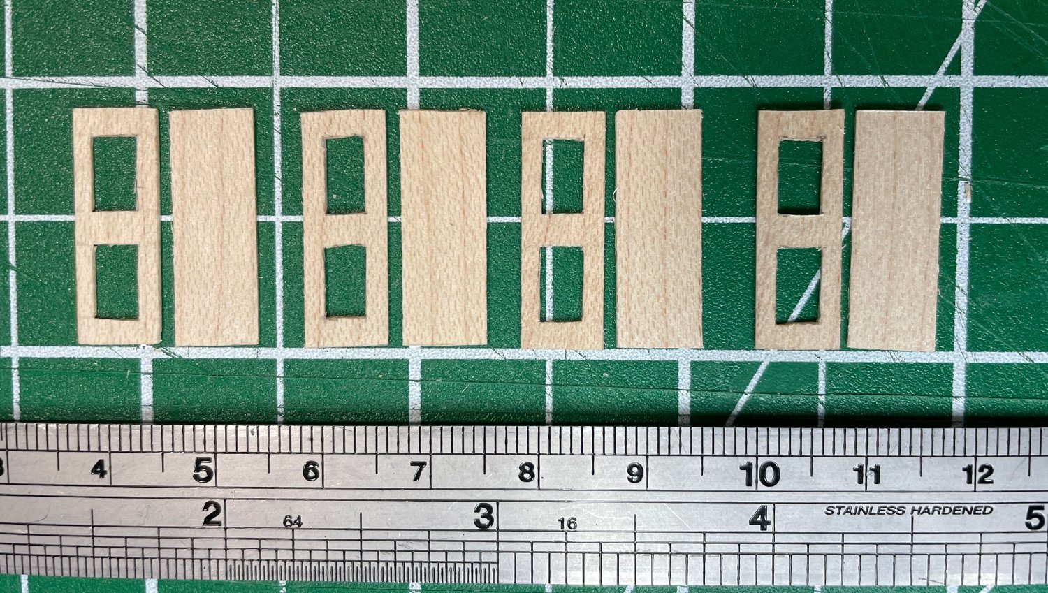
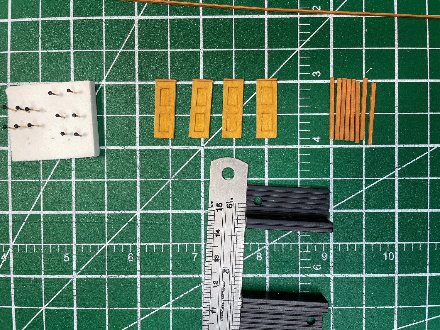
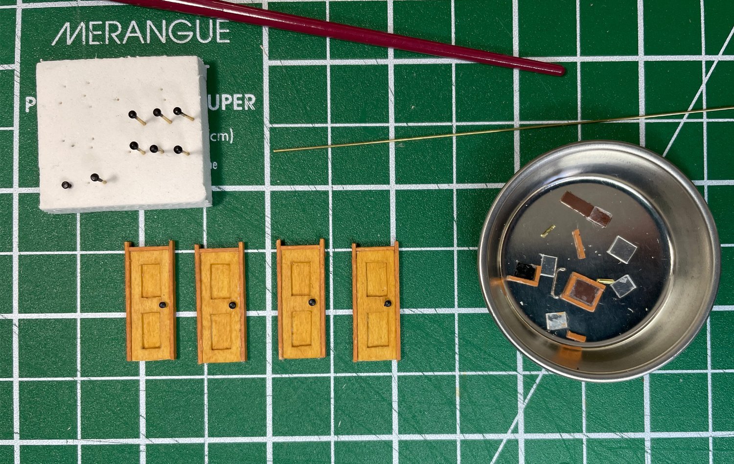
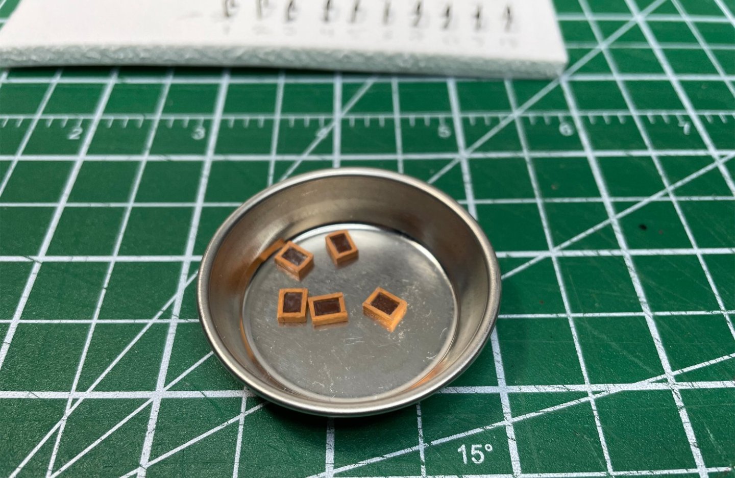
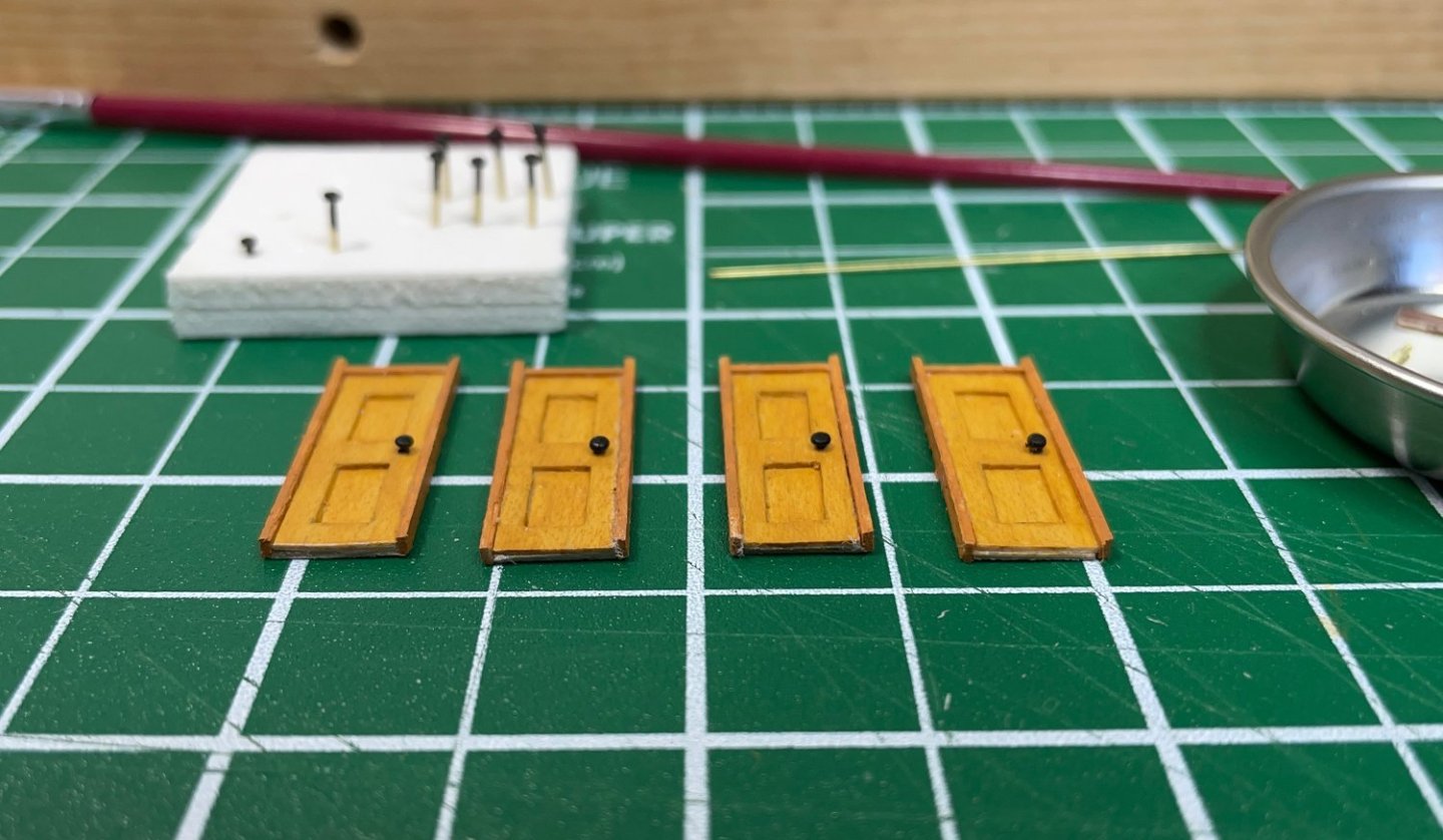
Speaking of 99 ways... I'll come to the windows in a minute! But the final production of the doors is done! The version of the doors I went with are made up of two layers, a backing layer which also become the interior panels and a second piece that sits on top to become the door stiles and rails. Then I added thin stips on the two sides and across the top to represent the door frame itself. The side frames will reach up to the bottom of the deck above (thus they look like they stick up a bit). The doorknobs were made from the small brass pins/nails provided in the kit. I wasn't happy with their size ...they looked a little too big. So, I chucked some pins in my rotary tool and gently touched a file to them to flatten the tops a bit and reduce the diameters slightly. Once I was just about finished with the doors, I realized I still had to do something with the windows before I go ahead with installing the doors and planking the bulkheads. I had already decided I wasn't happy with photo-etched brass window squares provided in the kit. I might have been able to live with painted brass doors, but the windows just didn't sit right with me ...particularly after all the effort with the doors! So, you may have noticed the dish of window parts in the second to last picture ...which are some of the remains of a few of my test attempts. I think I might be on version six...? I won't say more until I'm sure I've worked it out... but I think I have! More on that in the next post. Back to my windows! Rob


-
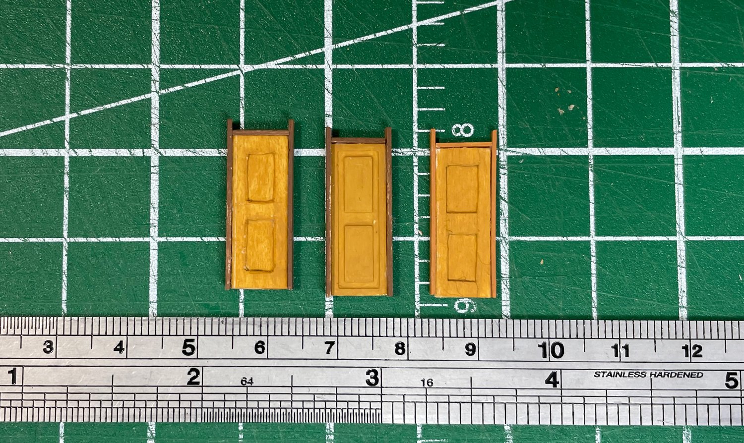
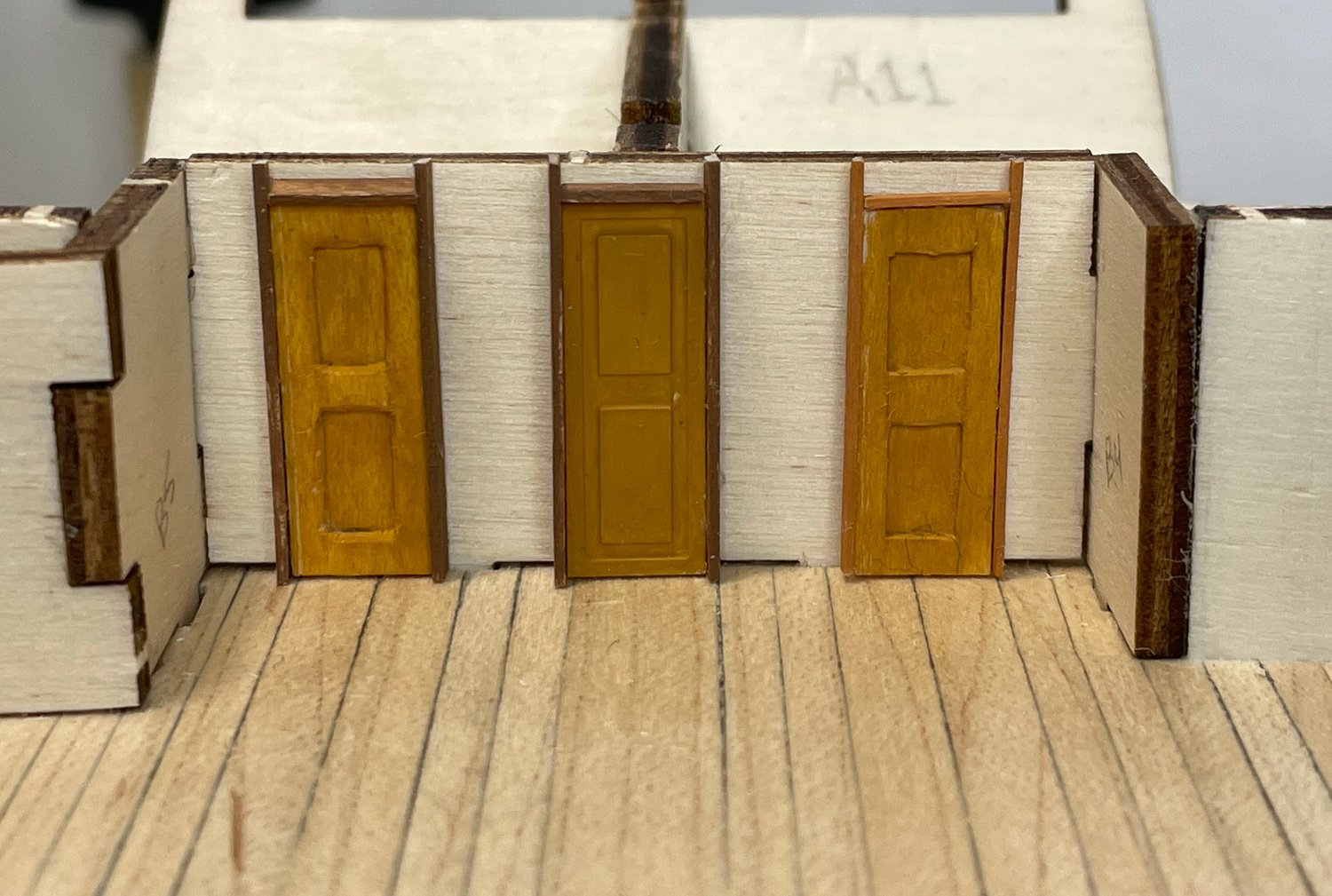
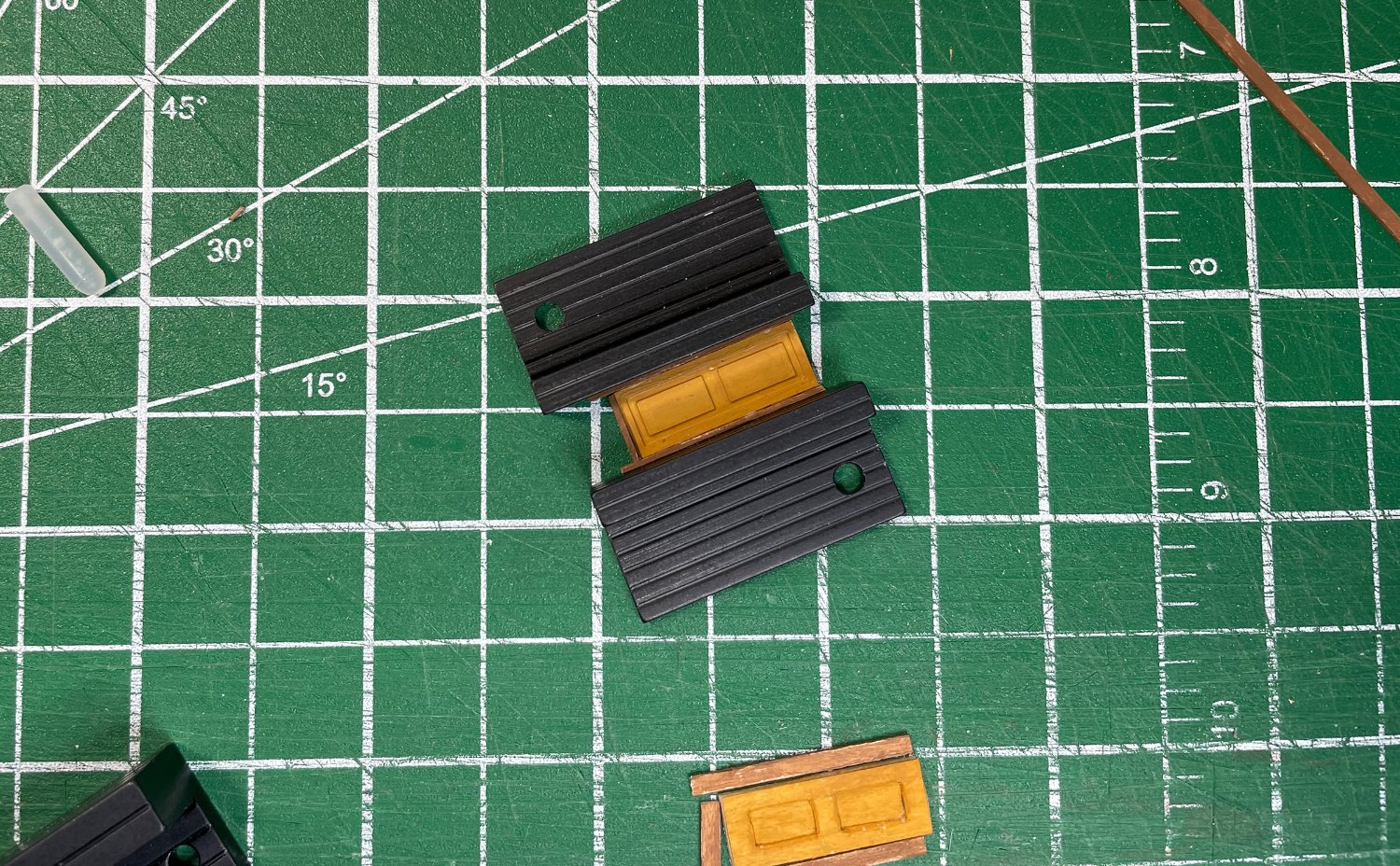
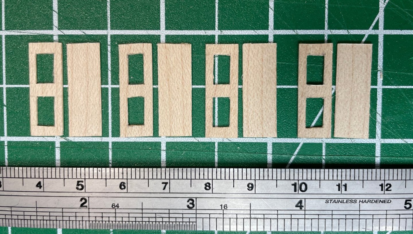
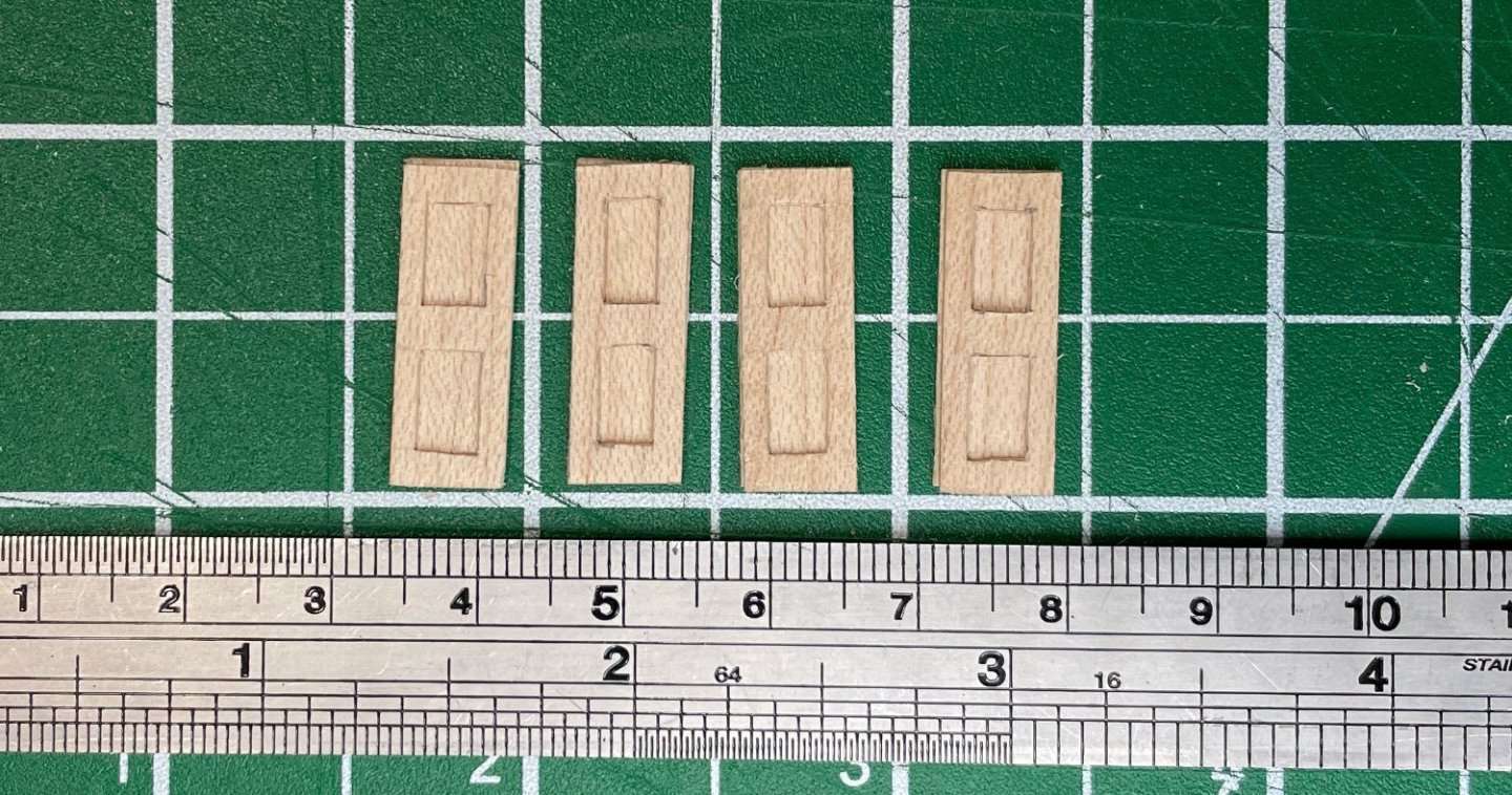
One more try at the doors... I couldn't leave it alone. I decided to try building another door. My first rough attempt at the doors and frames were a little too thick (protruding out from the bulkhead too much. I wanted to try and make the door and frame a little thinner (and the frame lighter in colour). On the left is my original attempt at making a door, the middle is the painted brass part from before, and on the right is my new attempt with a little more care taken and thinner door and frame. Still not happy with how it looks in a zoomed in photo, but looking at it on the ship at a normal viewing distance, it actually looks much better. Once again, it's more relevant to look at them on the ship, so in the photo below they are temporarily installed on the bulkhead and not necessarily in their correct places (and not quite as zoomed in!)... ...and lastly with the overhanging deck (more like what you would actually be able to see)... I did a better job with the door in the last attempt, but it's still hard to compete with the clean lines from the brass part ...especially when just doing it by hand (no fancy machining involved). I like the lighter thinner door frame ...it still gives the door a bit of accent without being obvious, and probably more like what would have been done (everything would likely have been painted the same). I still have a minor irritation that in the brass part, the door panels are reversed as to how they should be, maybe I'm the only one who will ever notice but I still see it. But the lines in the brass part are certainly crisp and clean. I meant to take a picture of how I made the door but I got too involved in the building and forgot to take a picture! I just used two very thin pieces of maple (0.5 mm thick), cut the squares out of one and then glued the two pieces together. Which make a nice representation of a door with two panels. After which I added very thin strips of wood as a door frame (0.6 mm wide and 1.2 mm deep ...so it will protrude out slightly from the door itself). Not complicated, gives a good effect but it is still tough to get everything completely straight at this size when only using a knife and a ruler. Looking at the last door now, I just realized the top frame piece on the door isn't actually straight! Oh well, it was just a test ...I'll have to make sure I get them bang on for the real thing. Now I have to actually make the decision ...hmmm. Rob

-
@Whitebeard, thanks for the offer of the files ...but I don't have a 3D printer. So for now, it's still making bits by hand! I have to admit it's cool what you've done with the 3D printing. Rob
-
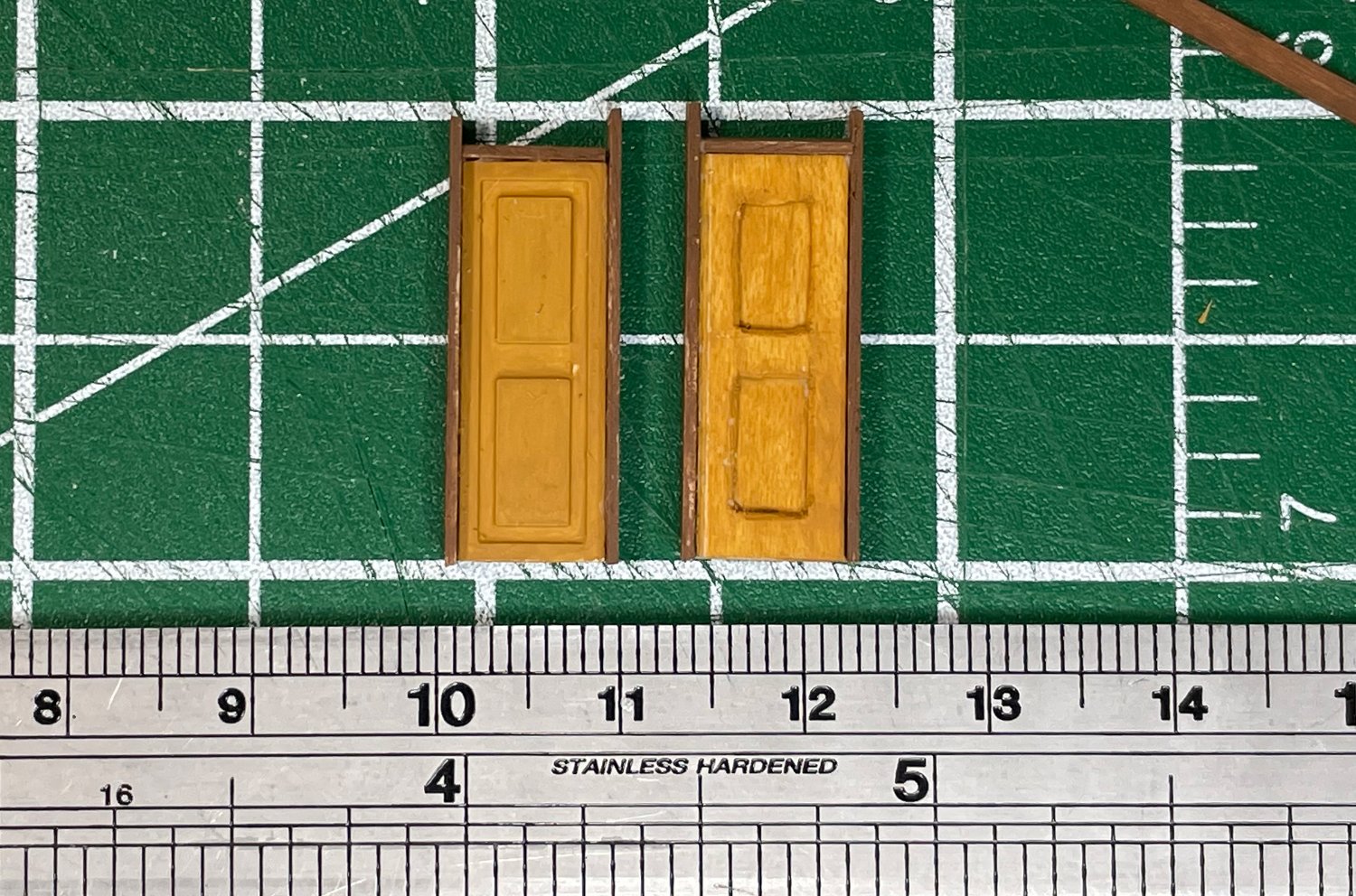
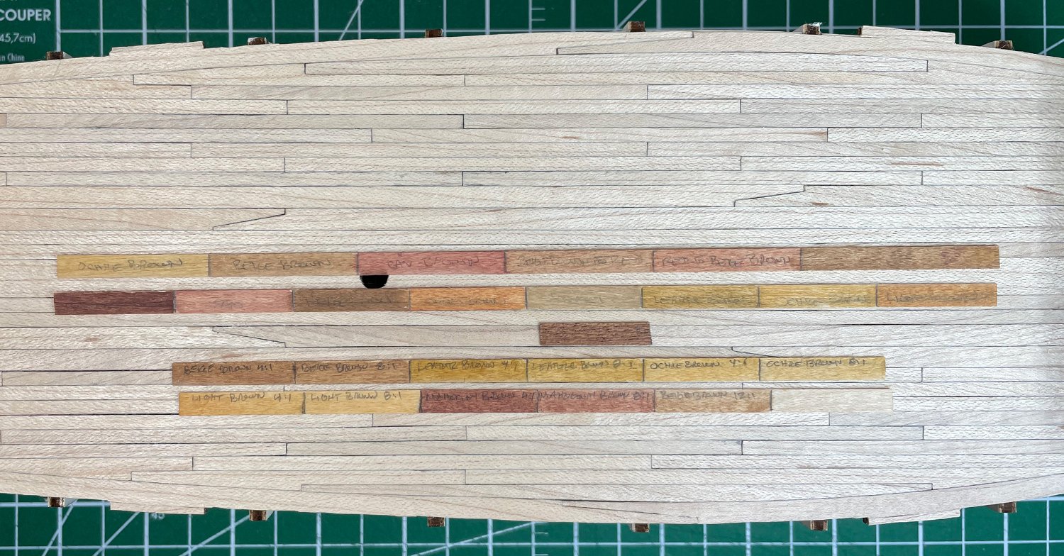
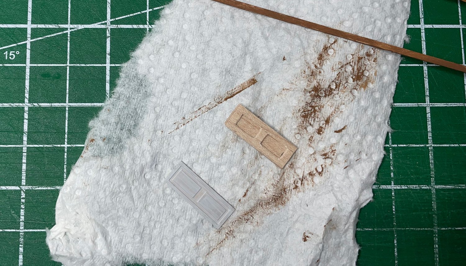
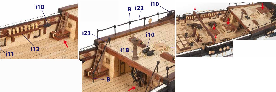
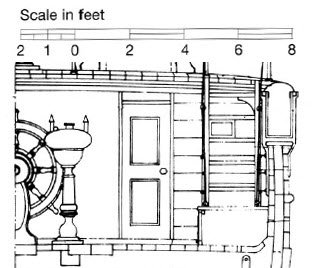
Doors and bulkhead planks have occupied most of my model thinking over the last couple of weeks. Well, I was actually working on another project, but I wasn't completely ignoring the ship! The doors in the OcCre kit are photo-etched brass parts, which the instructions just have you glue onto the bulkhead as is. Well, that of course won't do ...that's too simple , and more importantly doesn't look right (since I'm not going for the varnished wood and brass look for this build). The plans from Marquardt's Anatomy of the Ship suggest something in about the same size, but with a slightly different look (modified plan image from AotS below). Also, a door would normally have some sort of a door frame (...done enough DIY home renos to know at least that much!), even on a ship! So, my options are either to prime and paint the brass parts or build something out of wood to replace them ...and add a door frame in either case. Not being sure which way to go, I decided to test the two options by building one either way (at least a quick test build). I wanted to see if I could build a more accurate door that I would be happy with or just go with the painted brass part. The wood door is a little more accurate to how a door is constructed, but even if you consider that I did a quick rough test job, it might still be difficult to match the fine lines from the photo-etched piece. I also would put a second coat of paint on the wood door if this was my final piece, to disguise the slightly out-of-scale grain pattern. Of course, any tiny part in a zoomed in photo is going to look a little rough, so the real test is with the doors installed ...so I temporarily placed the two doors in position on the bulkhead. ...and with the deck (and overhang) in place... I could have done a more careful job on the test wood door, but I think I am still going to prefer the look of the painted brass part (even if it's not quite accurate construction). I think adding some kind of door frame really improves either option, so that is going to be a given. I'm leaning towards the painted brass part ...unless someone talks me out of it! I think the door frames in the test are a little too dark ...I might be able to live with them as they are, but I think it will look better if I go a little bit lighter colour (give a bit of contrast, but just a bit). Now, the planking on the bulkheads. The 5mm wood strips provided in the kit are just too wide. From the Anatomy of the Ship plans, it looks like something in the order of 7" to 8" would be about correct, which translates to about 3.3 mm at 1:60. Since I planked the deck with my own maple, I have lots of the sycamore strips from the kit to cut down without worrying about running out of stock. That decision is easy enough. My last decision with the bulkhead planking is the colour. I wanted the deck to be a lighter colour than the surrounding wood (a holy-stoned deck and all), which means staining/painting the rest of the material (bulkheads, bulwark lining, skylights, etc.) some subtle contrasting colour, but not so much that it messes up the real contrast from the sapelli parts. Here is a composite image from the OcCre instructions to get an idea of the areas involved and the sapelli parts to consider... ...and some colour tests I was messing with laid out on the deck (that's a little piece of sapelli in the middle)... Most of the colours I think are too dark, but I'm leaning toward a heavily thinned ochre brown or heavily thinned light brown. More of a stain to pull the wood off the bleached wood colour, but not hide the wood grain entirely. Enough to visually seperate from the maple deck, but not really appear dark. If anyone want to venture an opinion, I'm always ready to listen. Now, while I make up my mind about those things, I have to get back to installing the deck planks on the forecastle and the quarterdeck. Rob


-
@Whitebeard …no I haven’t made that mistake …not yet! 🙂 In the photo in the previous post I hadn’t actually put on the planks yet …the lines are just “guidelines” I drew on. But thanks for the reminder …I could certainly see myself doing that! 😃 Rob
-
Thanks @Cathead. I sent off a full text request to the author through ResearchGate…we’ll see what happens. Rob
-
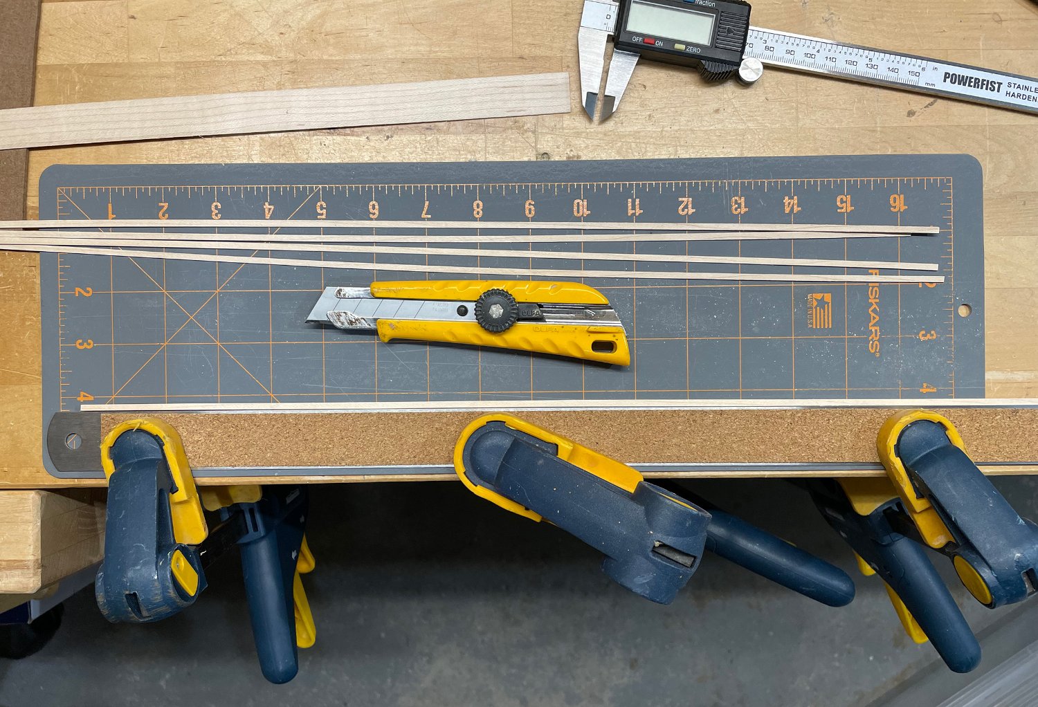
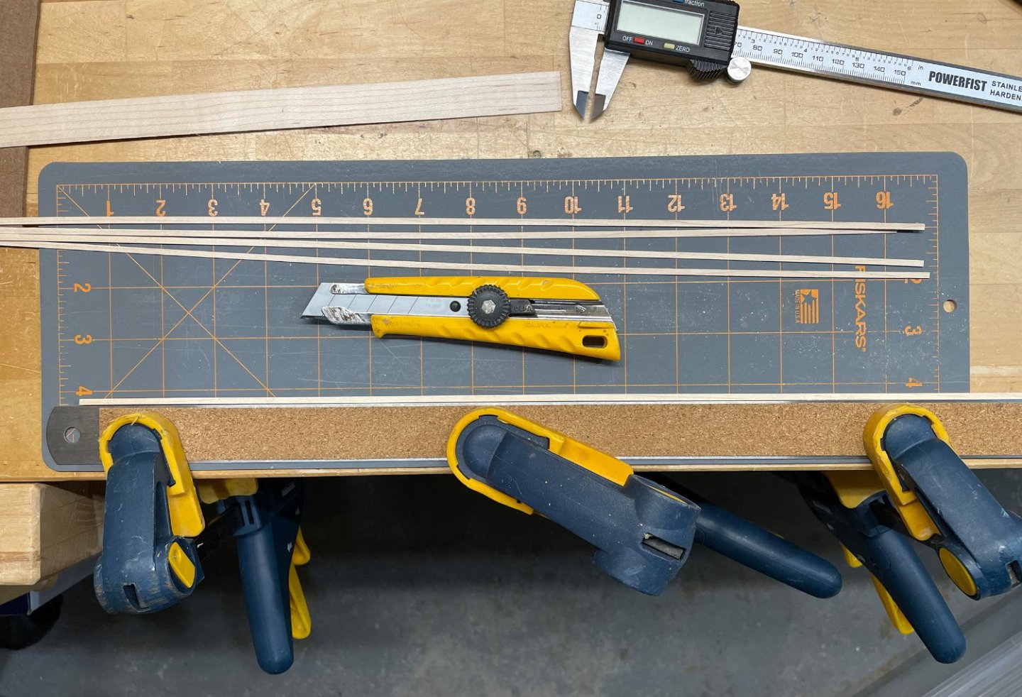
Thanks Whitebeard! I haven't posted much in the last couple weeks partly because I have been off researching how I will be altering the next steps! 🙂The "research" can get in the way of production time on the model, but I enjoy trying to figure out how things should look and what I could do to move in that direction with the model. First, I needed to cut some more maple planks for the quarterdeck and forecastle decks. My cutting jig worked okay, but I'm not happy with the consistency. I'm planning to rebuild the jig, but since I only needed a few extra strips of wood, I thought I should focus on building the ship over making another jig! 😁I also have caught myself a couple of times trying to figure out ways to do everything at the modelling desk ...when I have a modestly equipped little woodshop downstairs! So, rather than re-inventing the wheel, it was off to the woodshop. I clamped a steel straight edge to the edge of the workbench and carefully adjusted the wood to the precise width I wanted, tightened down the clamps holding the wood firmly and cut the strips with a utility knife. Worked great, but a little slow finicky setup with each cut. But I didn't need too many pieces, so this was the easy way out. I added some margin planks to the false decks of the forecastle and quarterdecks, and added some guidelines. No king plank or binding strakes on these decks ...and all the deck planks will run the full length of each. Now I just need to add the newly cut planks ...with some sniped planks on the quarter deck and some joggled planks on the forecastle deck. I'll follow (with some artistic license!) Marquardt's Anatomy of the ship drawings [adapted drawings below]. I've also added the bulkhead framing under the quarterdeck and forecastle (that's just the forecastle deck and quarterdeck just laying on top of the main deck!). That still leaves me with figuring out what I will do with those cabin bulkheads ...board widths, framing for the doors, framing at the corners, to stain or not, replace/modify the kit's brass doors and windows, etc. More research 🙂...and I think another post! Rob


-
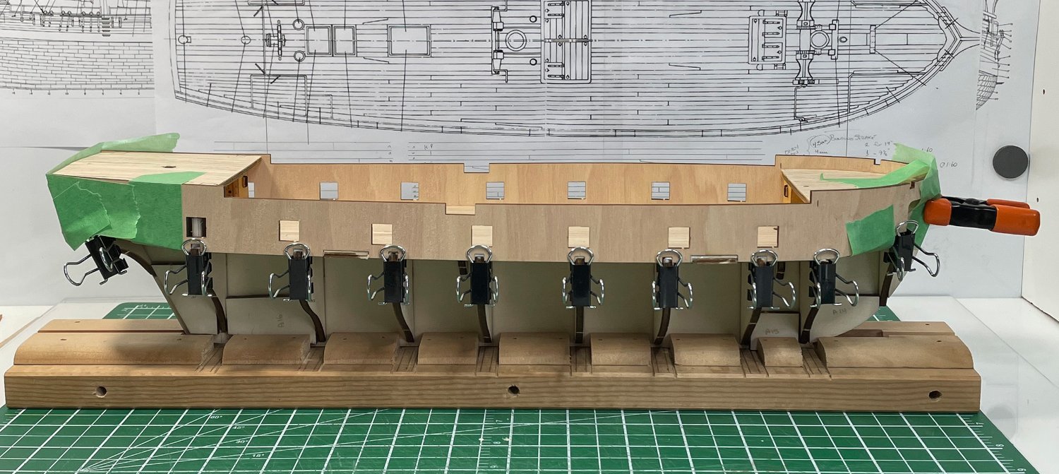
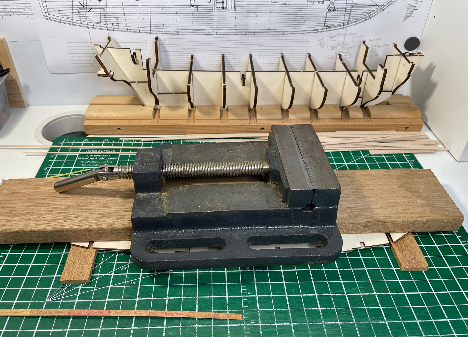
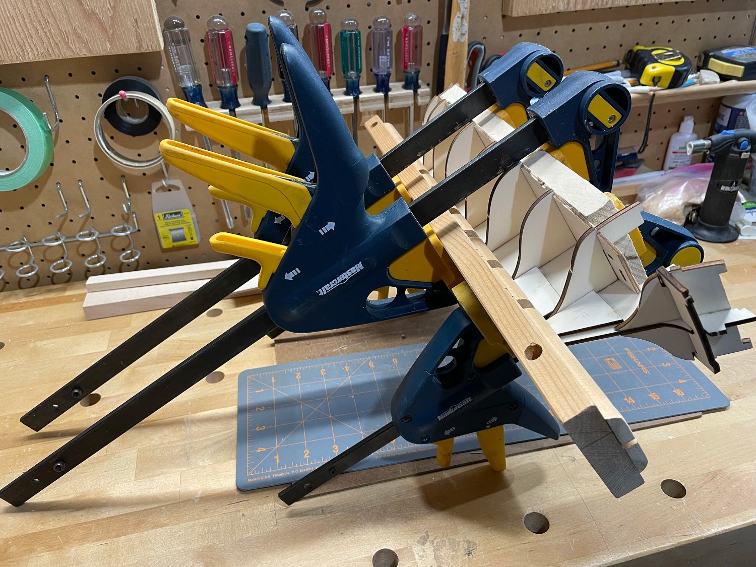
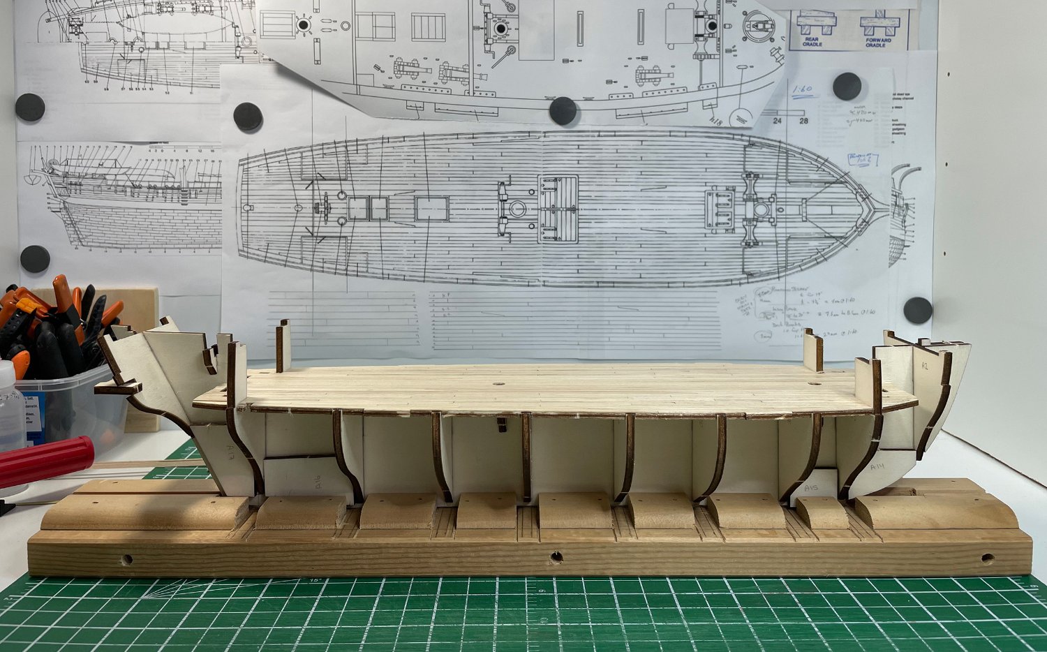
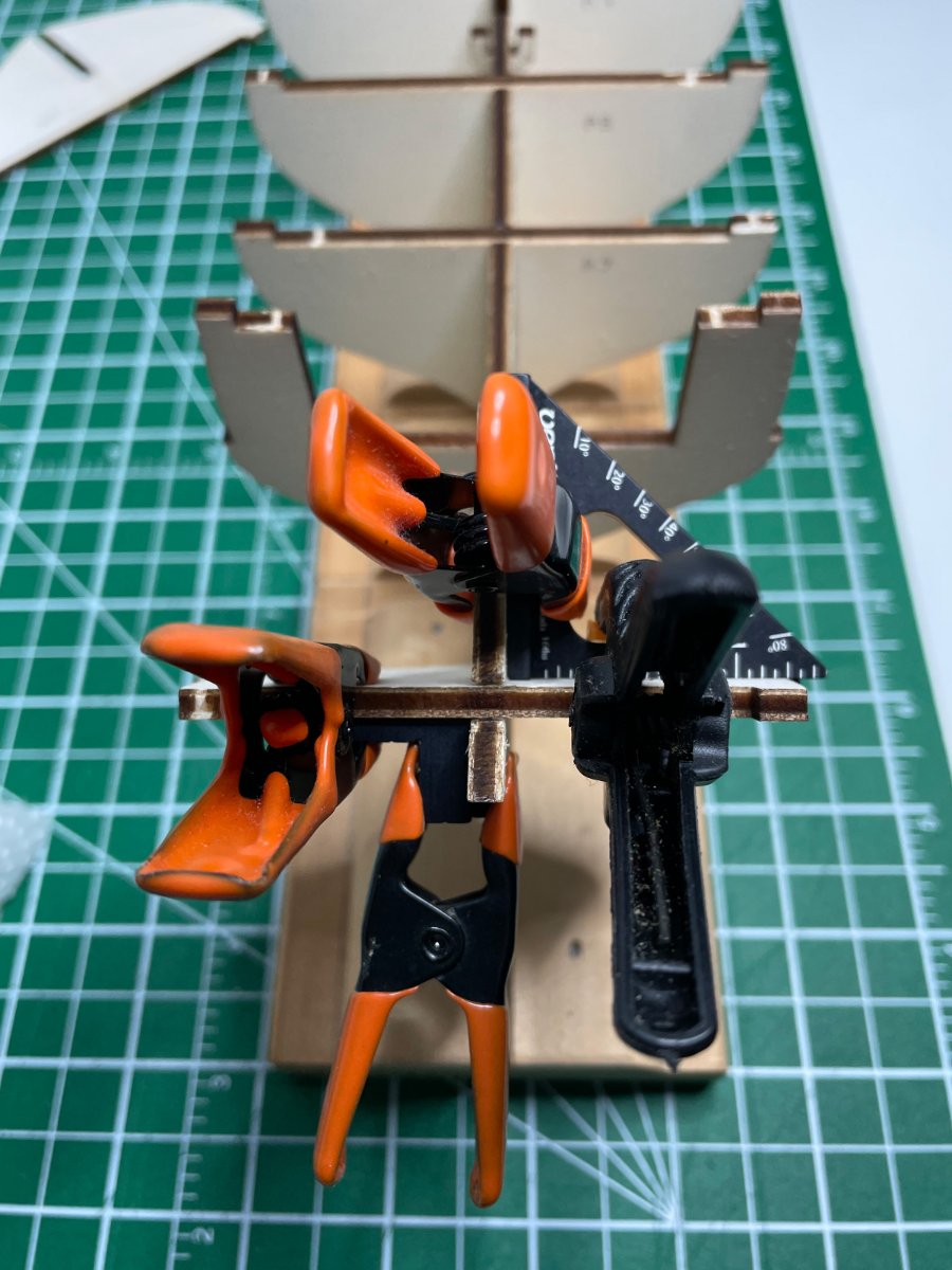
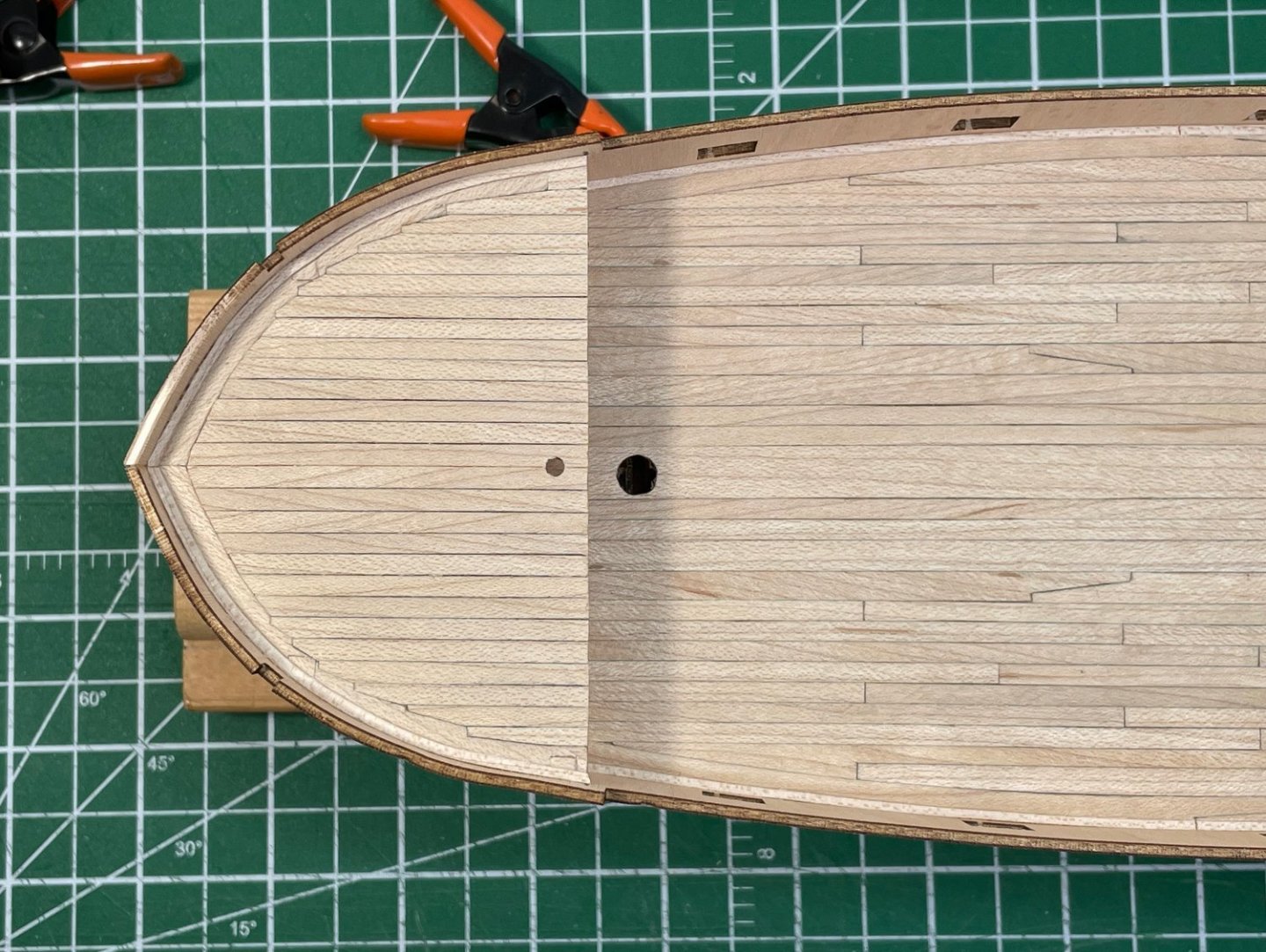
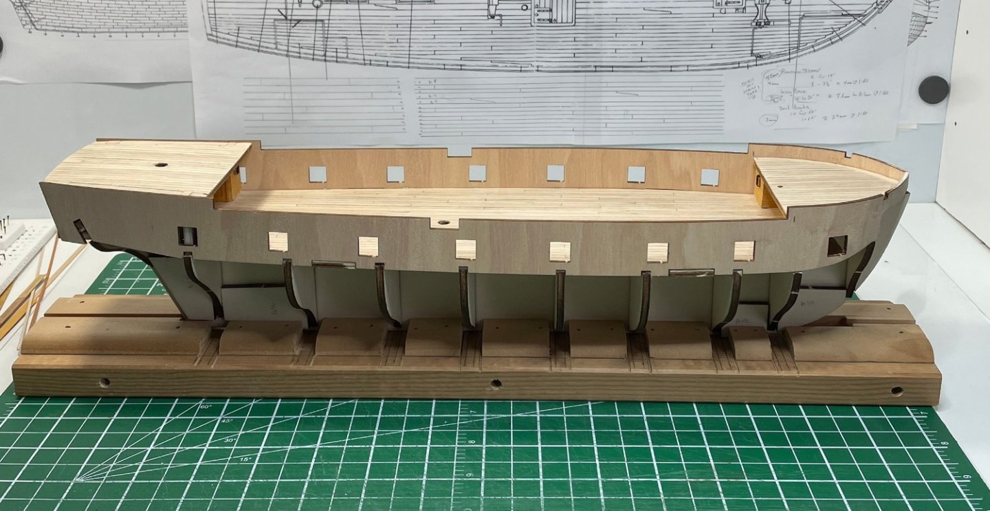
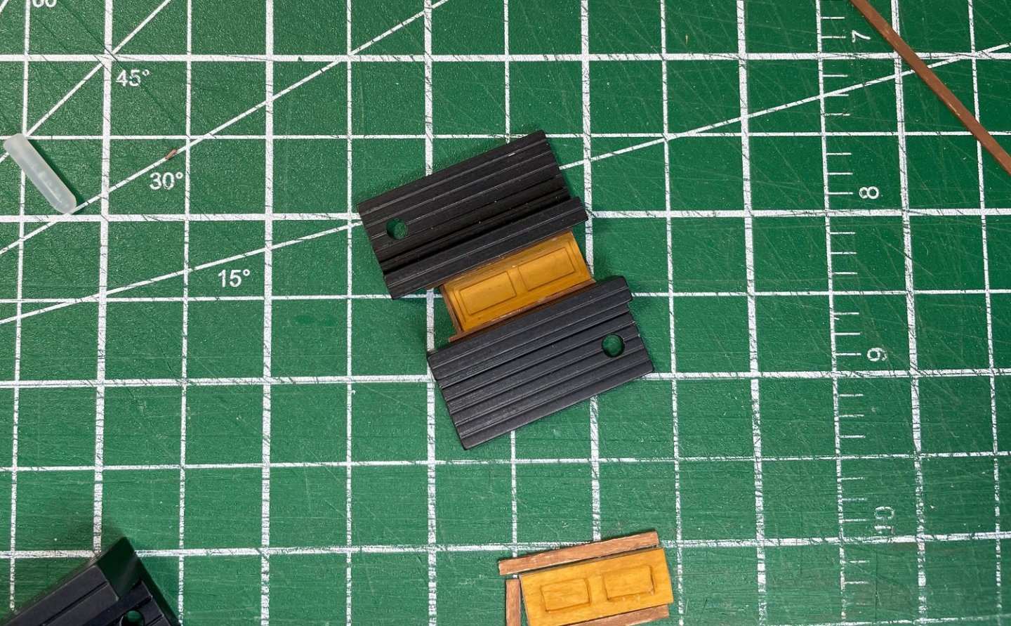
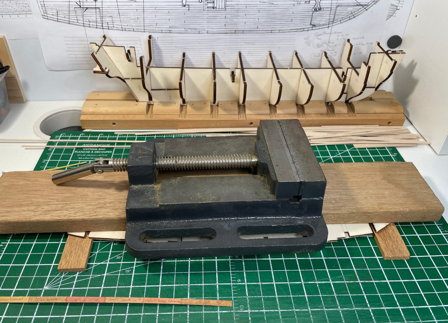
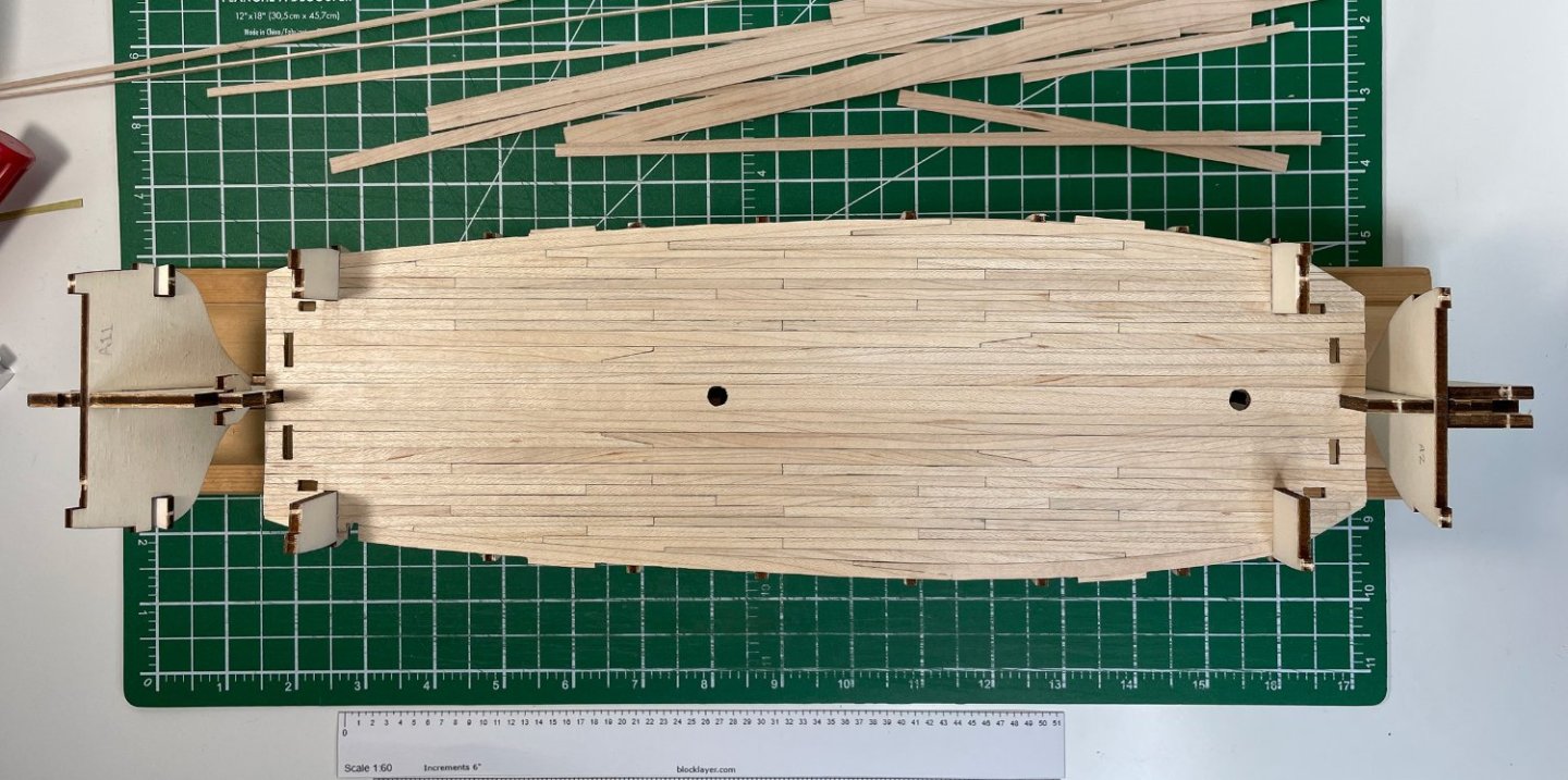
Help! A Kraken has my ship! ...well, not really... I was actually just installing the main deck on the bulkhead frames. As I was planking the deck (off the frames) the deck took on a slight bend as the maple deck boards were added. I put some weight on the deck for a few days which pretty much returned it to being flat (or at least pretty close). Then I tried various rubber bands and small clamps to make sure the deck would sit square on the frames, but most of what I had on hand wasn't really doing the job. Then I remembered I have a wood shop full of clamps! I put a small piece of wood across the deck to make sure the pressure was evenly distributed and gently tightened four big wood clamps around the hull ...my Kraken clamps! (see first photo) After leaving it over night, I released the ship from the Kraken! It looks good and straight. Here are a couple of photos of the deck installed... And a close-up of the deck pattern... All in all, I'm pretty happy with how the main deck has turned out. Now on to the forecastle and quarter decks ...or perhaps the main deck bulkheads? I'll have to decide which to do next. Rob


-
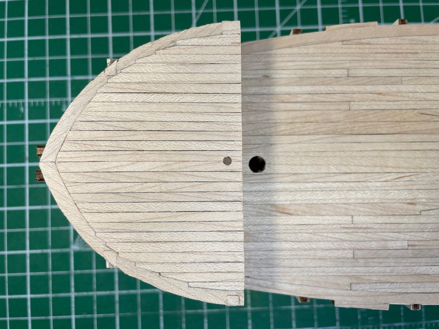
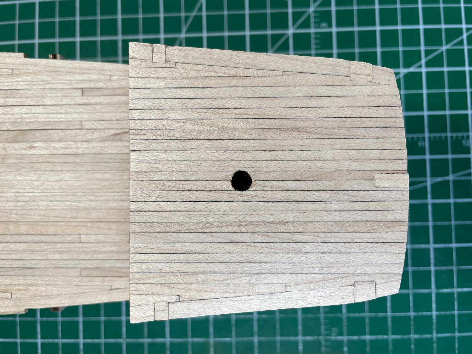
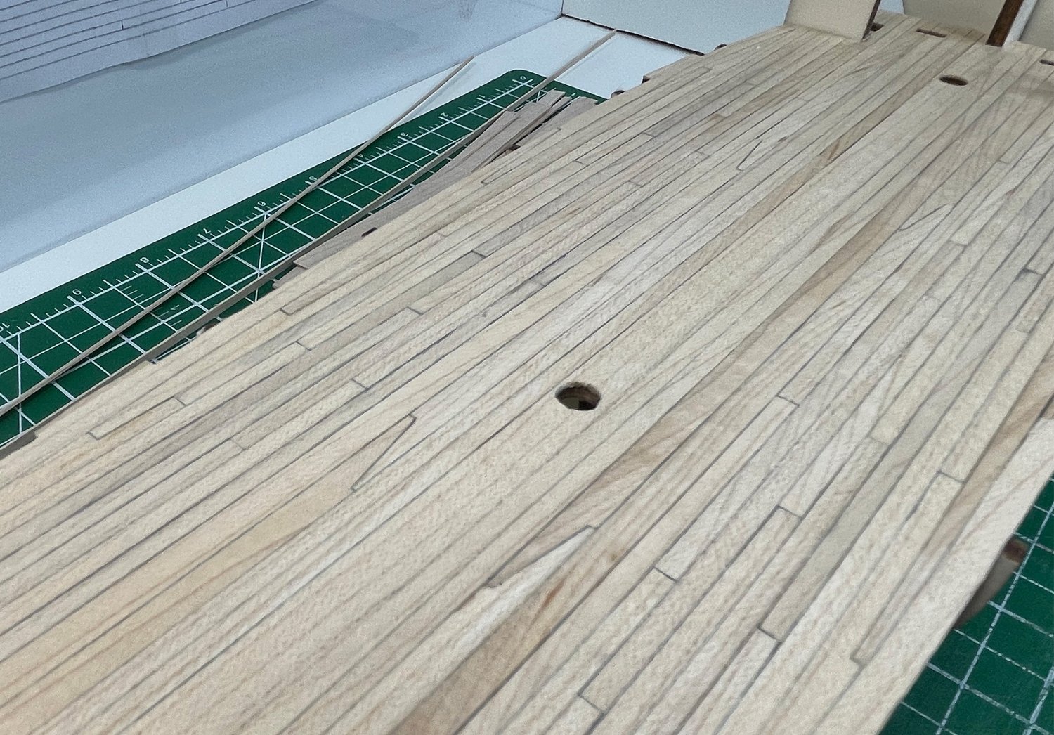
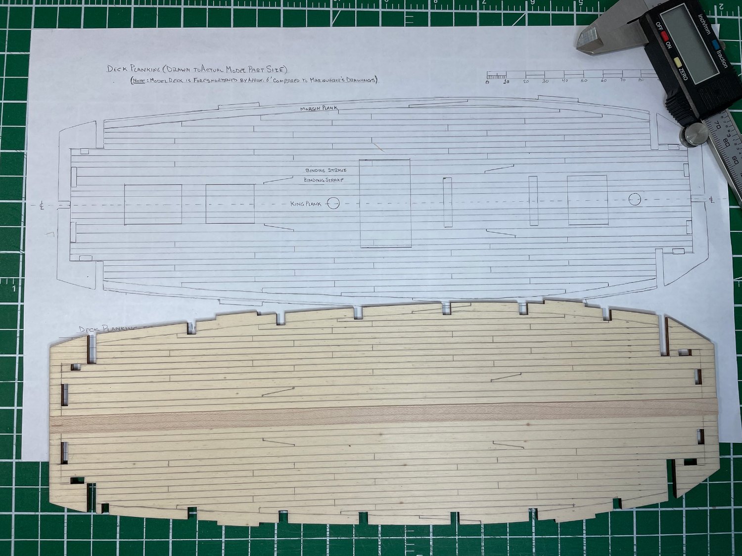
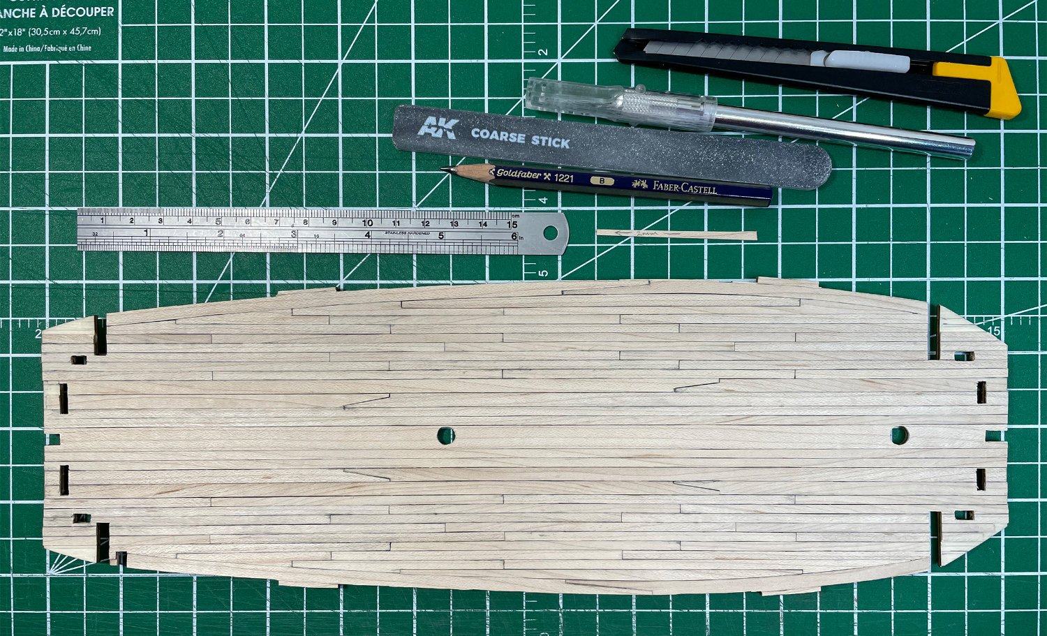
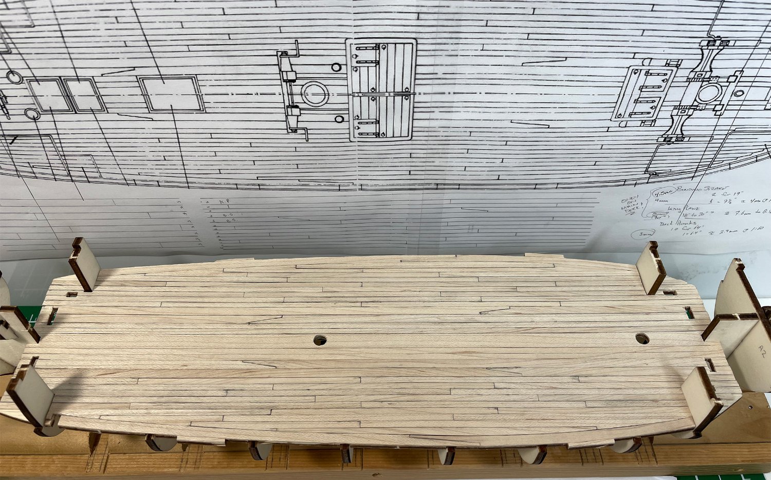
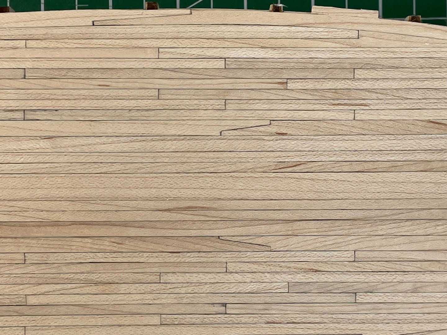
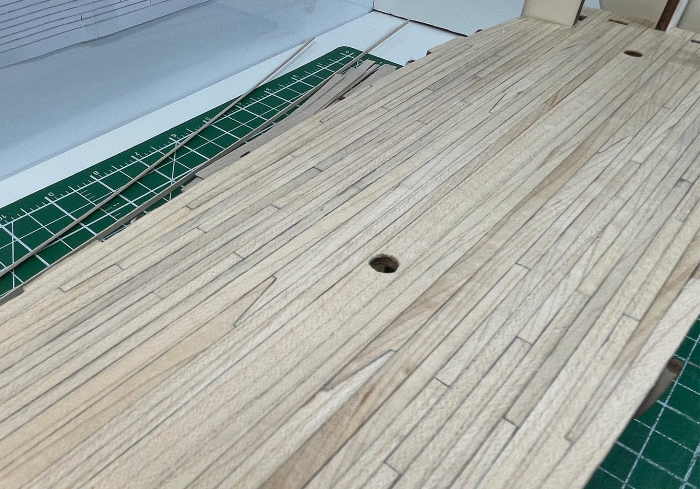
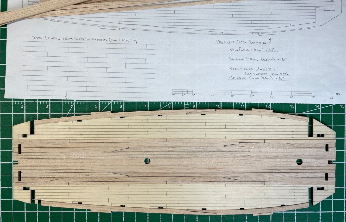
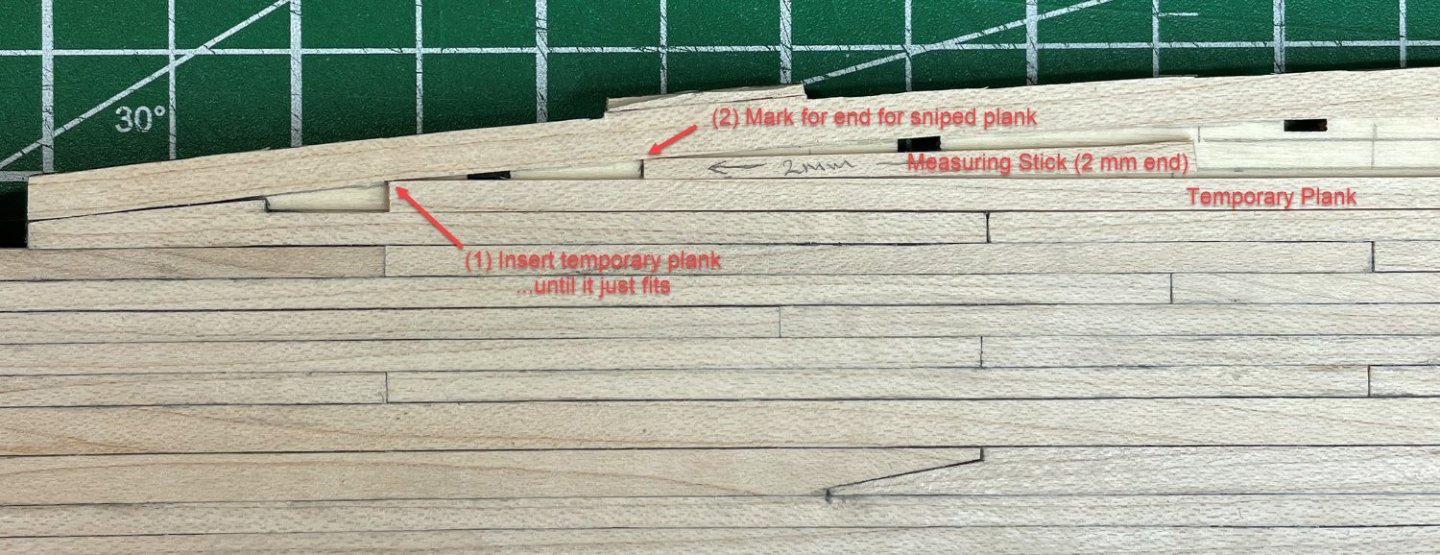
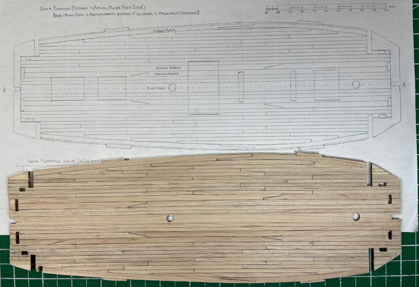
Planking the main deck... I started out by marking the false deck with the plank layout that I had devised to keep me running straight as a laid down the boards and as a reminder where I wanted plank butts to be, or the other various planks. In the picture below the king plank is already in place up the middle of the false deck. It was about at this point that I realized that my deck plank widths were not as consistent as I would like. The cutting jig I created worked pretty well, but there was some occasional minor wandering of the blade as it occasionally caught a bit of wood grain (likely more of an issue with maple over a softer wood like basswood?). I did play with using a stiffer knife blade in the jig to retrim some of the boards but the jig really needs something like a heavy utility knife blade, which won't fit on the jig arm as it's currently designed (I'll have to make an adjustment to the jig for next time). To even out the boards I stacked them with the one edge evenly together and taped the ends. I then used a cabinet scraper and a 2 inch wide piece of maple (3 mm thick) as a guide to scrape the stack of boards all to the same width. Only problem is that my guide board was closer to 3.1 mm. But I decided the boards were consistent and the width I had chosen was somewhat arbitrary anyway. As it turns out my binding strakes were also a touch over the intended 4.5 mm. So, between the deck boards and binding strakes being slightly oversized, I needed one less deck board on either side ...which made my guidelines drawn on the false deck to being more of just a guide than an exact template. The image below shows the first few boards on either side installed (out to the first deck board outside the binding strake) and the margin planks installed to the outsides. The keen eyed among you might notice the holes for the masts are slightly off center on the king plank. Sigh... . The holes are in the right place, but I managed to install the king plank ever so slightly off center. I didn't notice until I cut the holes for the masts (just before this picture was taken). There'll be enough stuff happening on the deck that I doubt this little flaw will be terribly obvious ...except to me! From here things went along pretty smoothly with the regular run of deck boards. Slowly gluing on the individual planks with PVA and using a metal ruler to make sure the boards were snugged together as I set them in place. I shaded the edges of the deck boards with a "B" pencil to simulate the caulking between the boards. When I finally got to the margin planks, I had to stop and scratch my head ...how was I going to accurately cut the snipe planks? Also, my guidelines drawn on the false deck were now only a rough guide (due to the slightly oversized planks) and the snipe board locations therefore changed. I sorted it out by sliding in the next plank and then a measuring stick cut to 2 mm wide to find where the snipe would land. I'm sure I probably just re-invented a common method for doing this! But it worked nicely. To set the curve for the outside of the sniped plank I used a compass to rough a line from the outside of the margin plank, but cut slightly outside this line and then sanded the board to a precise fit ...lots of subtle sanding. The sniped planks follow the general approach for the proper prototypical method, but I left myself a little artistic license to give the deck a good general look. The last boards on either side took the longest to install ...lots of fiddly little sanding. Here's the deck after the last boards were added. And the main deck temporarily placed on the bulkhead frames and set next to the deck as adapted from Marguardt's Anatomy of the Ship. I think it's giving a pretty good impression. And lastly, compared to my original design drawing for the main deck. Next, I have to sand and seal the deck before installing it on the bulkhead frames. Rob


-
That's frustrating! Looking at pieces L54, L56 and L58 (the stem and stern pieces for the two similar boats), they are all very similar but each subtly different (and their orientation makes a difference as well) ...and then you have to adjust to fit the hull as constructed! I've been keeping a list of things I would like to add or change on this build, but recently started another list of things to watch out for from issues encountered in other build logs. This one makes the second list for sure. 🙂 If it's any consolation, you're helping me! 😄 Rob
-
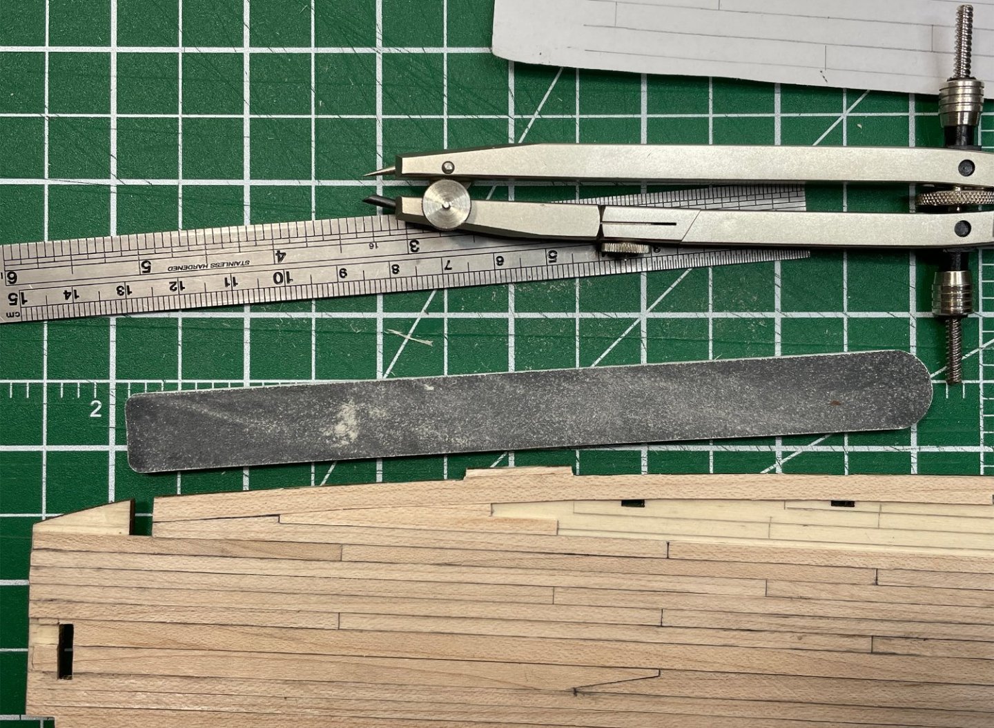
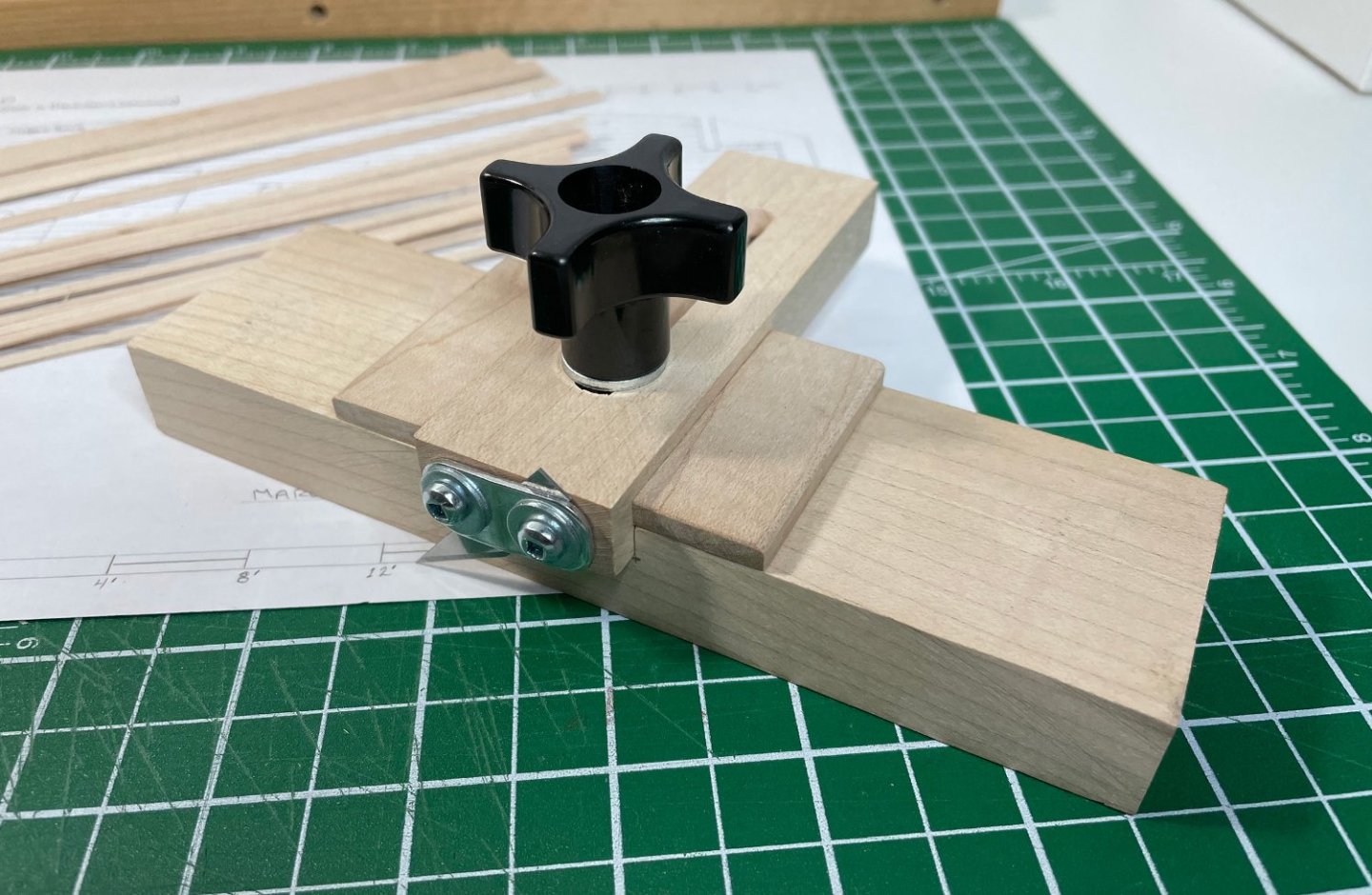
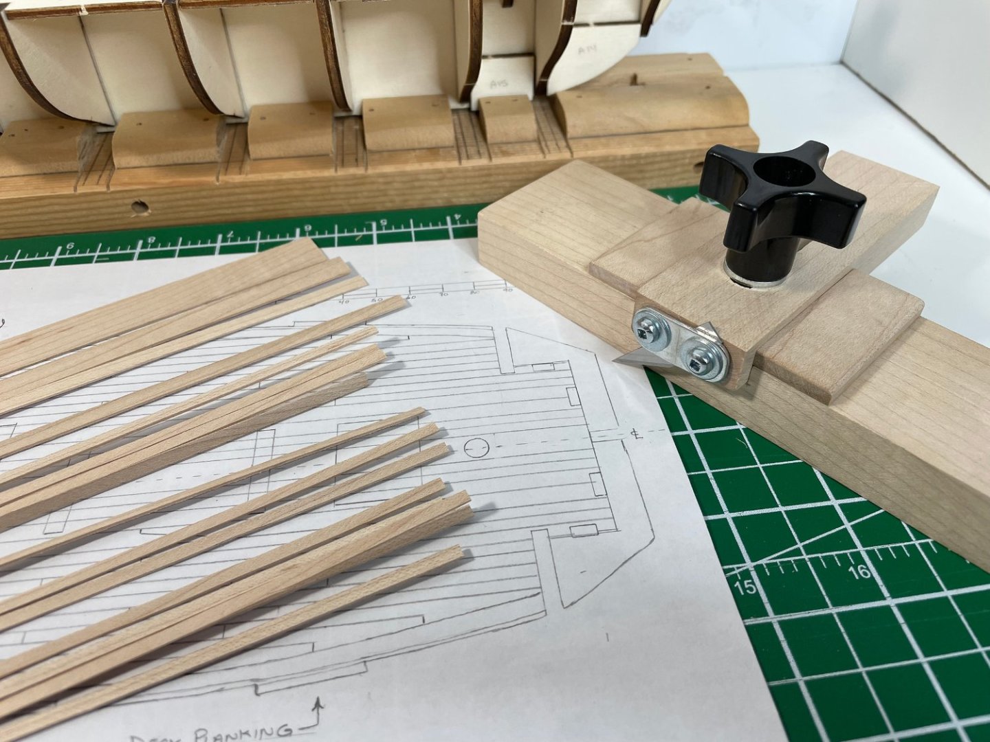
...to treenail (trenail, trennel, trunnel??) or not to treenail... I played a little with my test board, and I'm not happy with my attempts at "faking" the treenails. And trying to put in actual treenails in these 3 mm width deck boards might be a bit tricky (at least for me! ). I'm having trouble making them look good (not overly obvious, too contrasty, or just winding up kind of messy) and at the same time to keep them to scale. So, I've decided I'm passing on that bit of detail (at least for this build ...I'll give actual treenails a go on the next one). I'm going to be putting in deck planks that are a close to scale, with appropriate joints, a king plank, binding strakes, margin planks etc., that "should" give a nice effect even without the treenail detail. My next challenge was cutting the 3 mm deck boards. I went to my local hobby store to see if they had a "balsa stripper" tool ...which they didn't currently have. I started to search the internet for one and came across the image of one made out of wood and thought "Hey, I can do that!". So, back to the shop and using some left-over pieces of maple I made a strip making tool. It's just a straight board (roughly 6" by 2") with a 1-1/4" wide dado for an adjustable crossarm and a #11 blade secured to the end of the arm. I put a couple of shoulders along the crossarm for good measure, but I don't think they were actually necessary. I held the wood down with a metal cork-backed ruler (to keep my fingers out of the way of the blade!) and ran the tool down the edge of the board. The sharp edge of the hardwood tracked nicely, even with the wood only being 0.8 mm thick. That was a nice surprise, I thought I would have to come up with some way of guiding it at that small thickness. Generally, it worked pretty well. There was a couple of learning moments, but most of the planks worked out well. The maple strips took at least four passes to cut through (slow and easy keeps everything straight ...don't try to cut all the way through in one go). The basswood only took a couple of passes but was much easier to get carried away going quicker and then making a mess of the straight line! I've decided I'm going with the maple for the deck boards. I like working in the harder wood for detail stuff and should allow me better success at cutting nice, neat board joints (especially in the binding strakes and along the margin planks). I've got enough material in the various widths to start working on the main deck. First, I'm planning on laying out some guideline on the false deck. We shall see if the boards fall precisely on the lines, but at least they'll give me an indication if anything is going out of line and as a reminder as to where the board joints should be. So, enough with figuring out what to do and manufacturing scale lumber, back to actually adding pieces to the ship! Rob
-
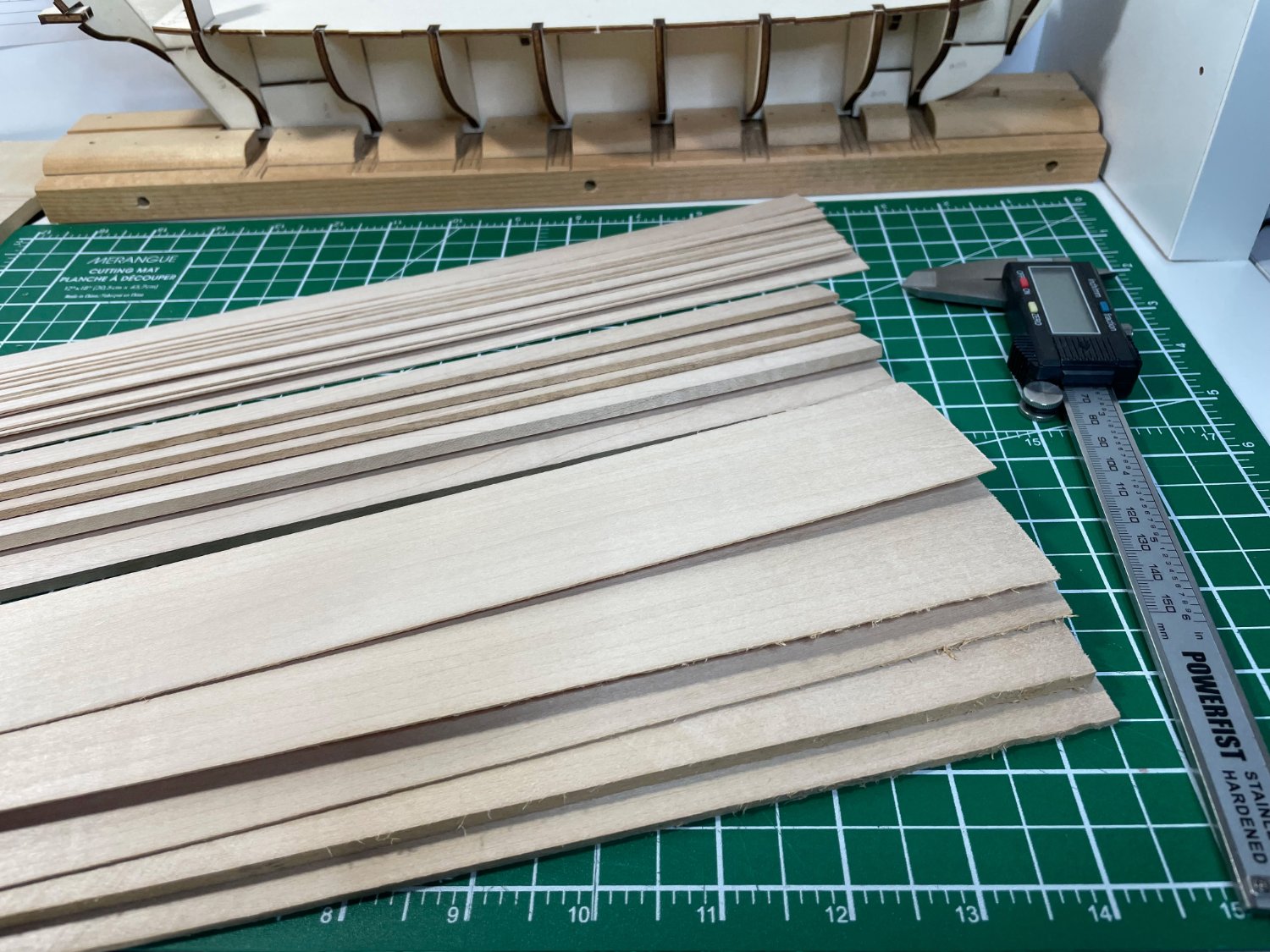
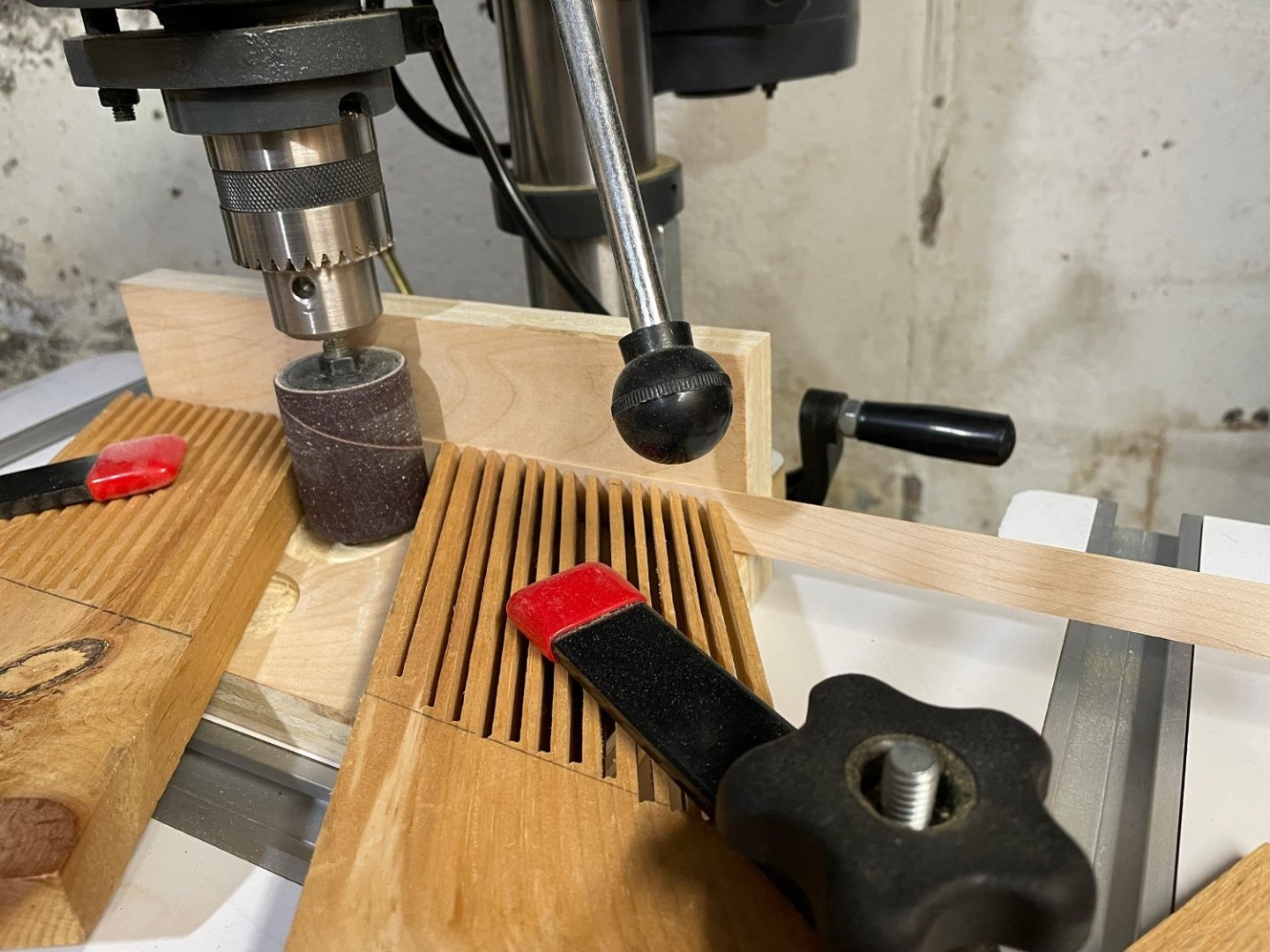
...I'm looking forward to seeing the results too ...this may take a while! 😬 I still haven't settled on which wood to use for the decking, but I have thickness sanded all the boards I milled last week. I set up a small drum sander on my drill press and a right-angle fence and a couple of feather boards. It worked pretty good! The wood for the deck planks is 0.8 mm thick (in both maple and basswood). The sycamore in the OcCre kit is nominally 0.6 mm but in reality is 0.5 mm thick. Since all the deck will be the same species and thickness, the difference doesn't look like it will make any differnce ...as long as I don't mix them together. While I was at it, I also milled and thickness sanded a little extra wood (both in maple and basswood) for replacement parts or additional items in 2.5 mm and 5 mm thicknesses. All together that should give me a good stash of extra wood! I still have to settle on treenails or not. I think I am leaning towards not on these small 3 mm planks. I'm thinking it's going to start looking very busy and that might possibly become distracting...? I guess I will have to add some to my test board and see what happens. Next I need to set up a jig to make sure I cut consistent 3 mm plank widths ...without nipping the tips of my fingers! I think I have a design in mind that is similar to the balsa stripper you see in the model aircraft forums. Back to the shop and see what I can create! Rob

-
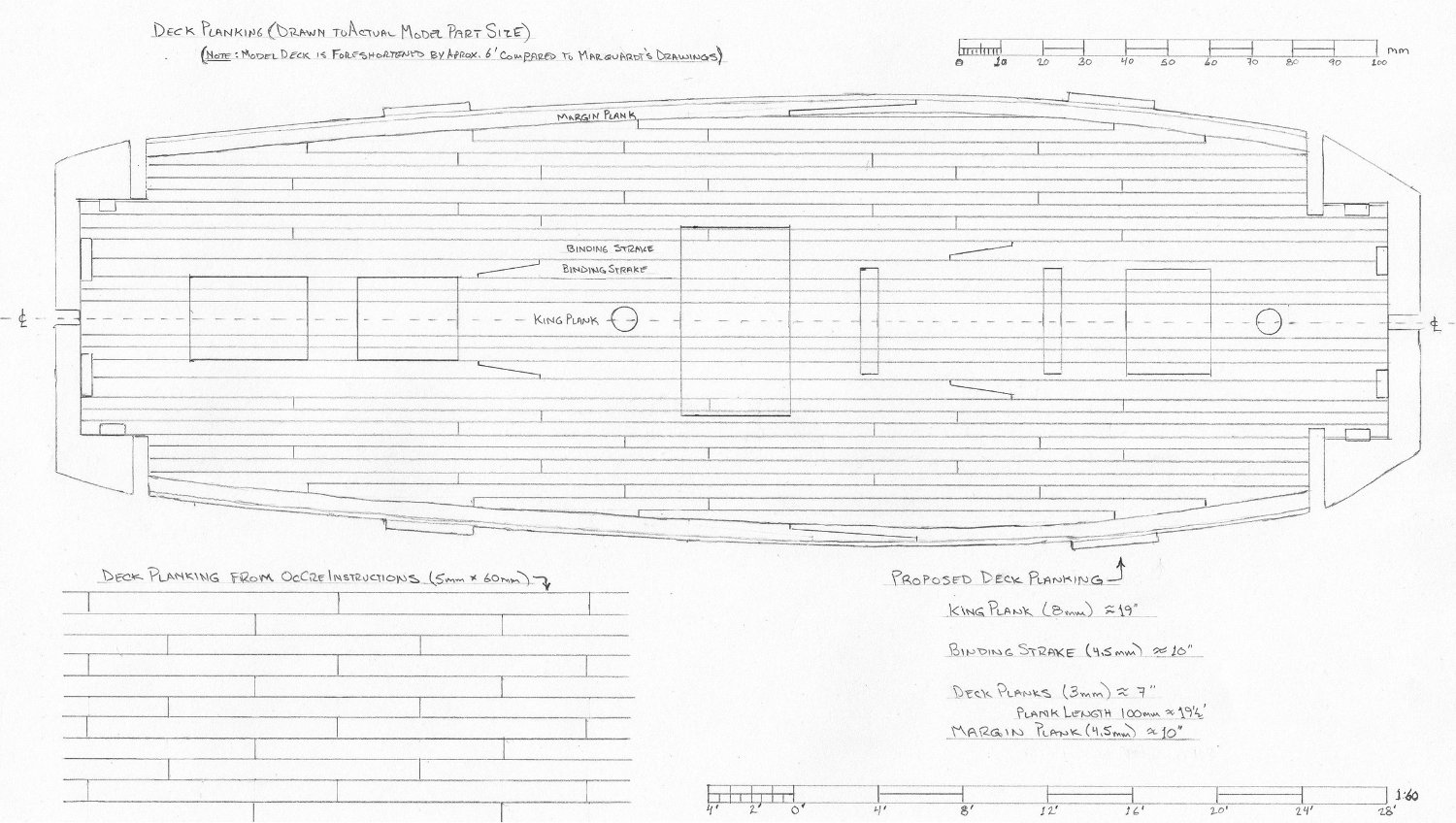
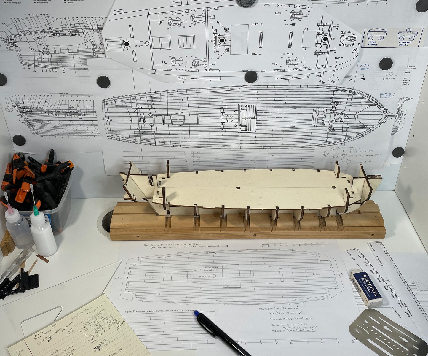
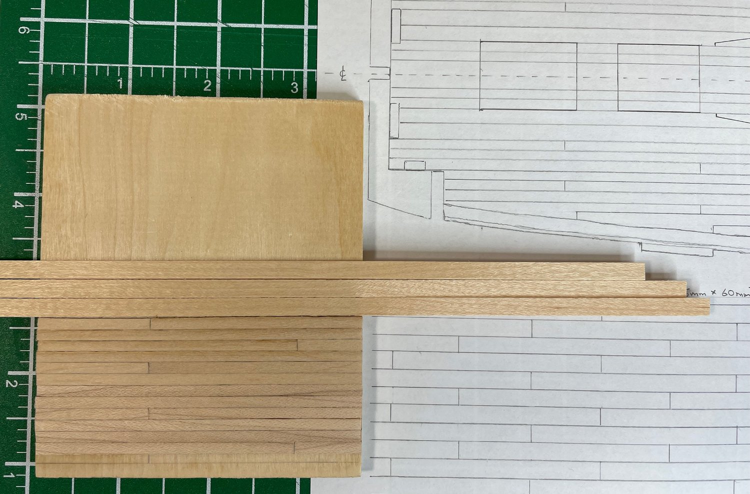
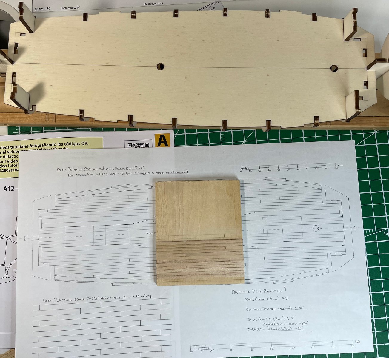
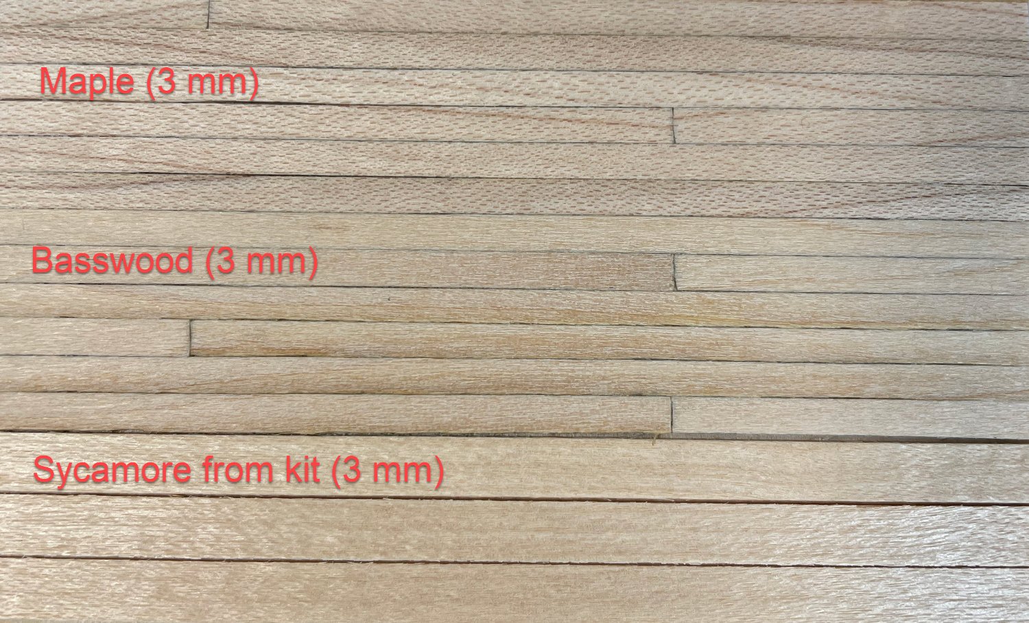
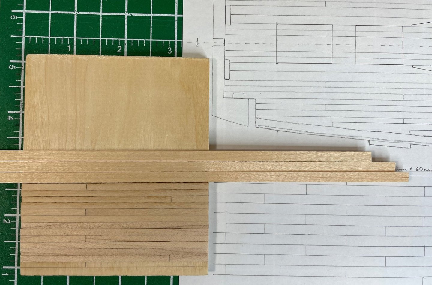
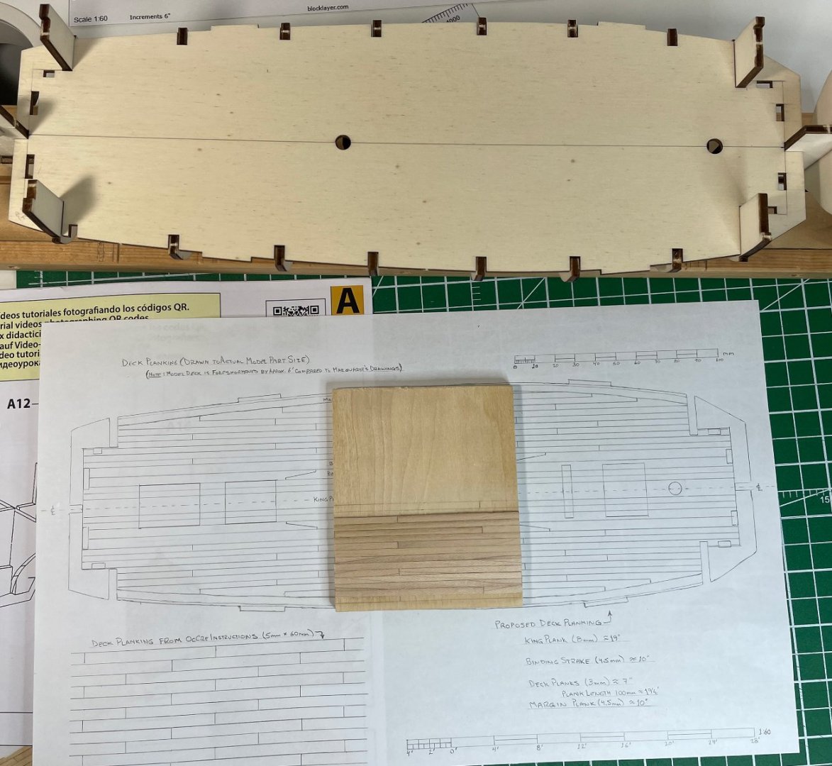
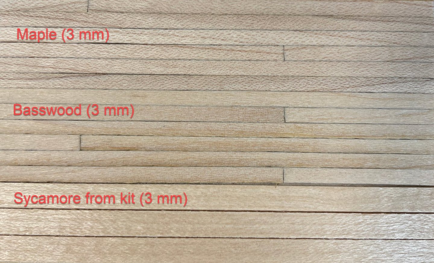
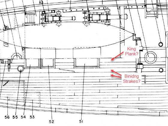
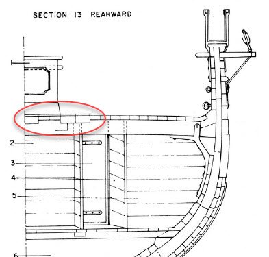
I've been quietly working in the background trying to figure out my approach to the deck planking. I was trying to figure out how to bring it a little closer to prototype scale and pattern. After some playing and calculating, I figured that 3 mm plank widths (rather than 5 mm in the OcCre instructions) would give a better look and be close to prototype. That would bring the planks to around 7" wide at full scale. In my calculating, I also discovered that the OcCre kit main deck is about 6 feet shorter than what is drawn by Marquadt in his Anatomy of the Ship! Which means I had to play around with the deck plank layout a bit. I decided to put on an artistic eye and go for getting the right look, even if my plank layout has a couple of technical issues in it ...but I think it gives a prototypical feel. I'm also going to include an 8 mm king plank (~19" at full scale), 4.5 mm binding strakes and margin planks (~10" at full scale). These may not be exactly correct, but they are doable and give a good approximate look. The king plank and binding strakes are only going to be included on the main deck ...if I understand it correctly, they would only have been installed on the main deck and not on any raised foredeck or quarter deck. The next problem is whether I had enough material to cut down the 5 mm sycamore provided in the kit to use as 3 mm width planks, or would I run out? After a little calculating, I think there probably is enough to do the decks but then there likely would not be enough for lining the interior of the bulwarks and other miscellaneous parts. Which means I would need to resaw some wood to make either the deck planking or bulwark lining. So, the question becomes ...can I resaw down to near 0.6 mm thickness to match the existing sycamore? I was pretty sure I could resaw maple or basswood (which I have on hand) down to 5 mm with some reliability, and possibly down to 2 or 3 mm. This led to some time in the shop making a lot of sawdust! As it turns out, down to 2 or 3 mm is no problem. When I tried for something a little under 1 mm, all I created was sawdust, but I could manage 1 mm and by the time a had sanded the 1 mm boards, it got a fairly consistent 0.8 mm (with some small variation). I can make replacement boards, but probably can't mix and match due to the differences in thickness between the sycamore in the kit and the maple and basswood milled in my shop. Also, could I actually plank at 3 mm? Time to make a test board! I think it turned out pretty good. It will certainly be more finicky and time consuming to install the 3 mm deck planks, but I think it will look a lot better. The sycamore from the kit is not really a fair comparison in the image above, it hasn't actually been installed on the test board or varnished as the maple and basswood have (I just laid them down beside for comparison). From a distance I like the maple but close up the grain patterns shows up a bit which betrays the scale a little (at least to my eye). Now I just have to decide whether the deck planking will be the sycamore, maple or basswood? Not sure yet which I will go with ...any thoughts are more than welcome! At least now I'm fairly certain that my revised planking plan is otherwise a go ...it will take a bit longer, but I think I will like the result. Now I have to go and sand the rest of the boards I milled! Rob


-
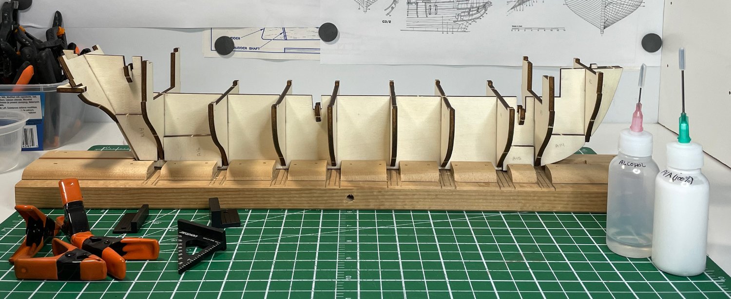
Picking up my build log from Post #5 which ended with "...I haven't messed up so far!" Well, I messed up! Out came the alcohol ...no, I mean to dissolve the PVA not the other! Luckily it wasn't really a big issue. I was starting to add the filler pieces between the bulkheads along the keel frame, when I noticed that the last bulkhead at the stern (Frame #11) was slightly twisted. I was sure that I had checked it before I left it for the glue to set (and after I took off the clamps!), but apparently, I wasn't being as observant as I thought (lesson learned). The bulkhead frame wasn't out a lot, but given that it was the last bulkhead, where other pieces attach on the stern, I figured I had better fix it. I gave the rest of the bulkheads a real thorough check for good measure. They all seemed good ...except for one other that was out slightly. I might have been able to just go with the #5 bulkhead and correct the rest while fairing the frames, but if I'm taking off the stern bulkhead anyway, I might as well do both and save any potential addition headaches from occurring later. At the back of the photo, you can see the stern bulkhead (the twist doesn't really show up well since the twist is in the other direction) and in the foreground you clearly see the slightly wonky bulkhead #5. I reset the two bulkheads and made darn sure they were straight this time, and that they would stay that way! They all look good now, and I've added in the filler blocks along the bottom of the keel frame toward the bow and stern. If you look carefully, you might also notice the last small horizontal frame to support the stern pieces is now also installed. I had to adjust my building board a little to accept the keel frame now with the filler pieces. Which is fine, this was always meant to be temporary. Once I add the actual keel pieces, I will have to adjust it again or find a different solution. I like @RossR idea of just using the provided stand ...or I could use the stand pieces as a template to make a more robust building stand? I'll cross that bridge when I get to it. Now it's on to planking the deck. I have to decide what plank lengths and offset I will be using, and whether I will try to include some of the other odd planks shown in Anatomy of the Ship. There appears to be a couple of wider binding strake planks along the edge of the deck houses and what I'm guessing is a wider king plank at the center. In section they appear to be raised slightly from the rest of the deck? Hmm? From my reading, it would seem to make sense that they were thicker planks (raised from the rest of the deck boards), but I'll probably go a little simpler. It might cause headaches down the road fitting the deck furniture. I'm going for a little extra authenticity not necessarily strictly authentic! But making them slightly wider and changing the butt join shouldn't be a problem. I'm already going to make the deck planks slightly narrower than supplied in the kit to bring them a little closer to scale width anyway. So, leaving a few slightly wider shouldn't be a problem. [Edit ...forgot to comment on plank length, etc.] I'm going with the 3-butt shift shown in Marquardt's Anatomy of the Ship. After trying to find information on deck plank lengths, I've decided to just go with what is shown in Anatomy of the Ship. That would appear to make them around 24 or 25 feet (with some variation), which translates to approximately 125mm plank lengths at 1:60. I figure if I generally do something along the lines of Marquardt's drawings, it will go a long way to looking better than the simpler OcCre instructions, even if it isn't perfect. I still have to decide about treenails or not. So, first I'm off to do a little testing. Rob


-
Hope I didn't open a can of worms here by introducing wood species! Let's try to pack a few of those worms back in the can. 🙂 Short answer ...no it shouldn't matter, at very least not in this case. Long answer ...yes, different species of wood have different properties. If you ask on this forum what is the best species to use to make a model ship (or for a specific task), I'm sure there might be a healthy "debate", or probably at least some strong opinions. I only introduced the topic of wood species to point out that the parts list in this kit seems to refer to the same material in one line as "sycamore" and another line in the parts list as "lime wood". It appears to be a reference to all the same material in the kit. Use the light colored thin 0.6 (0.5?) mm x 5 (4?) mm stuff for the deck boards (A20 and B11), bulkhead boards (B7) inside lining of the bulwarks (C3), gunport interior lining (H7), etc. In most instances in the parts list it is called "sycamore" and in only one instance it is called "lime wood". I think the lime wood reference in this case (B7) is a typo. What the actual species is, is not really significant to building this model. IMHO Rob
-
@RossR ...using the cradle is a good idea. Think I saw that in someone's build log, but I had forgotten that one. Thanks. @The Gimps Chimp ...yah, I thought about trying to make my own rope. I'm just afraid of another rabbit hole to fall down! The line provided in the kit is okay. With a little treatment/prep it could well be used ...but your rope definitely looks better! And then I could have more variation is sizes if needed ...hmm. I suddenly feel the ground sliding under me ...I can see into the rabbit hole now ...ahhh! 😄 I'm trying to keep myself from just purchasing replacement stuff. I want to try to build up my skills. So, I may well be making rope (or at least making the attempt) ...but that's down the road a bit. Rob
-
Hey Capella! I just pulled out and measured the planks in my kit and they come out as 0.5mm x 5mm x 600mm (both the sycamore and the sapelli). The thickness being a little off from the parts list is probably not much of a concern (0.6 vs 0.5mm) for the purpose it's being used (deck planks, hull planks, etc.) ...it's not likely to throw any other measurement off. Although I don't know why you only have 4mm wide boards? But, as LucinL mentions, it might actually put you closer to being in scale with the prototype (but double check you are looking at the right material!). The instructions assume you will put down a plank the full length of the main deck (about 340mm not 60mm lengths) and then put pencil marks every 60mm to represent the plank ends. Although, having said that, I'm considering actually cutting them to 60mm lengths (or whatever seems good for a prototype length) rather than using the pencil line approach. The parts list can certainly be confusing, such as A20 (deck planks) are listed as 0.6x5x340 which would be to cut 340 mm lengths from the 600mm material (which is about right to plank the main deck). But then B11 (deck planks for the raised decks at the bow and stern) in the parts list states 0.6x5x400 ...which presumably means to cut 400mm pieces from the 600mm material in the box, except that 400mm is way too long to cover those two raised decks ...strips in the order of about 90mm and 70mm (combined about 160mm) might be adequate, not 400mm as in the parts list! [...sigh] There is also potential confusion with species names. Common names of tree species vary a bit anyway, but then add in the usage difference between North America, Europe and Africa! Likely the kit is referring to the common names used in Europe (since it's a Spanish kit), but then throw in possible translation issues. I still believe there are a few typos in the parts list that refers to the wrong species (e.g. B7 is probably referring to sycamore not lime wood ...since there appears to be no 0.6x5mm lime wood ...assuming it even is lime wood!). I've found I need to stop, take a deep breath, check and recheck measurements, double check which part I'm supposed to be dealing with and how the instructions really show how it is used ...then suddenly I can interpret the parts list! 🙂 By the way, did you notice that OcCre has a set of YouTube videos to accompany the build? That may be another way to help sort out the parts list issues ...assuming the guy in the video did it correctly! 😄 Your build is looking good so far. I've already had to make a minor backtrack due to a bit of lack of attention before leaving a bulkhead to set! Rob