halituzun
-
Posts
137 -
Joined
-
Last visited
Content Type
Profiles
Forums
Gallery
Events
Everything posted by halituzun
-
 Thanks Bob, I hope it does !
 -
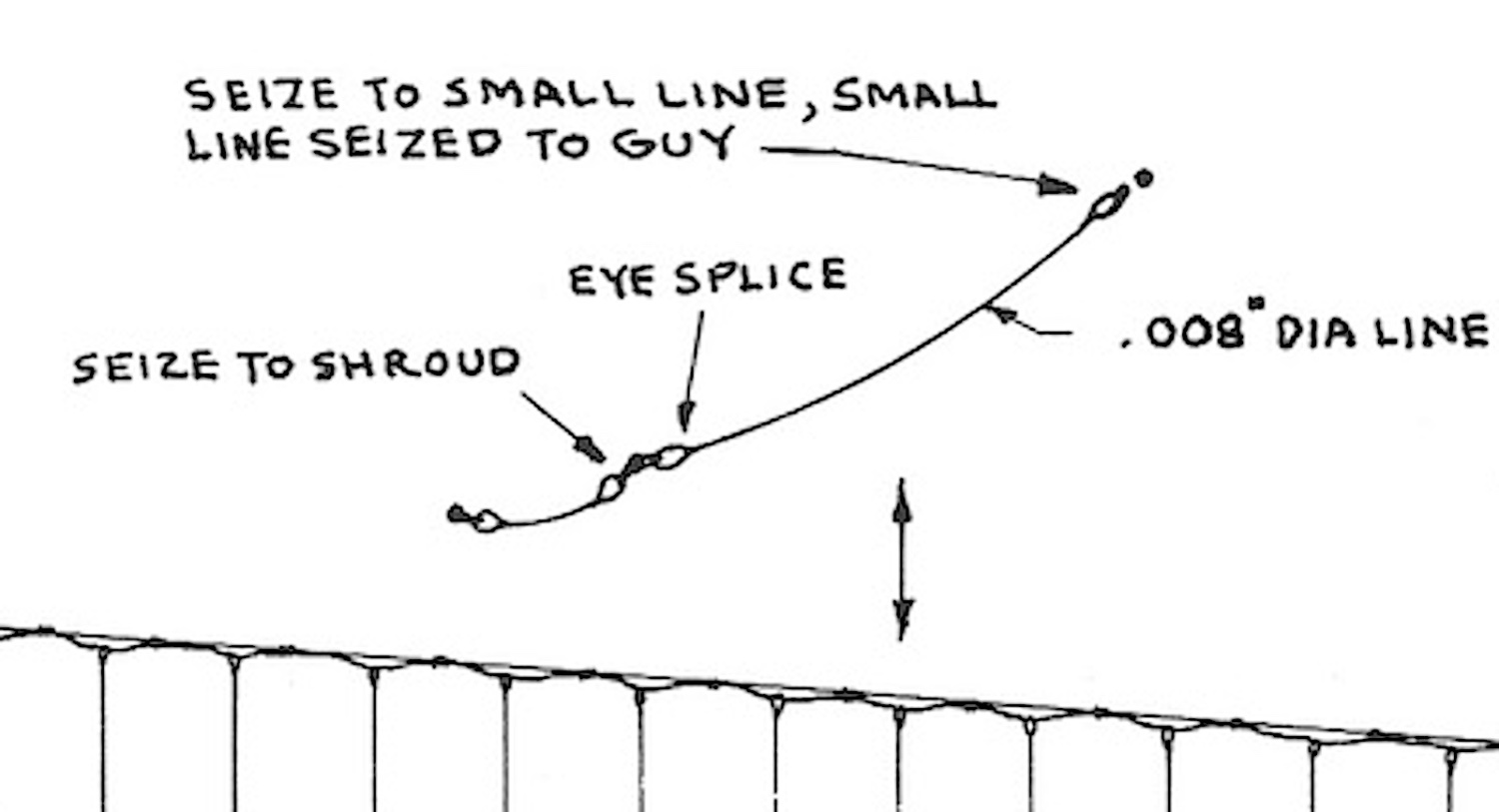
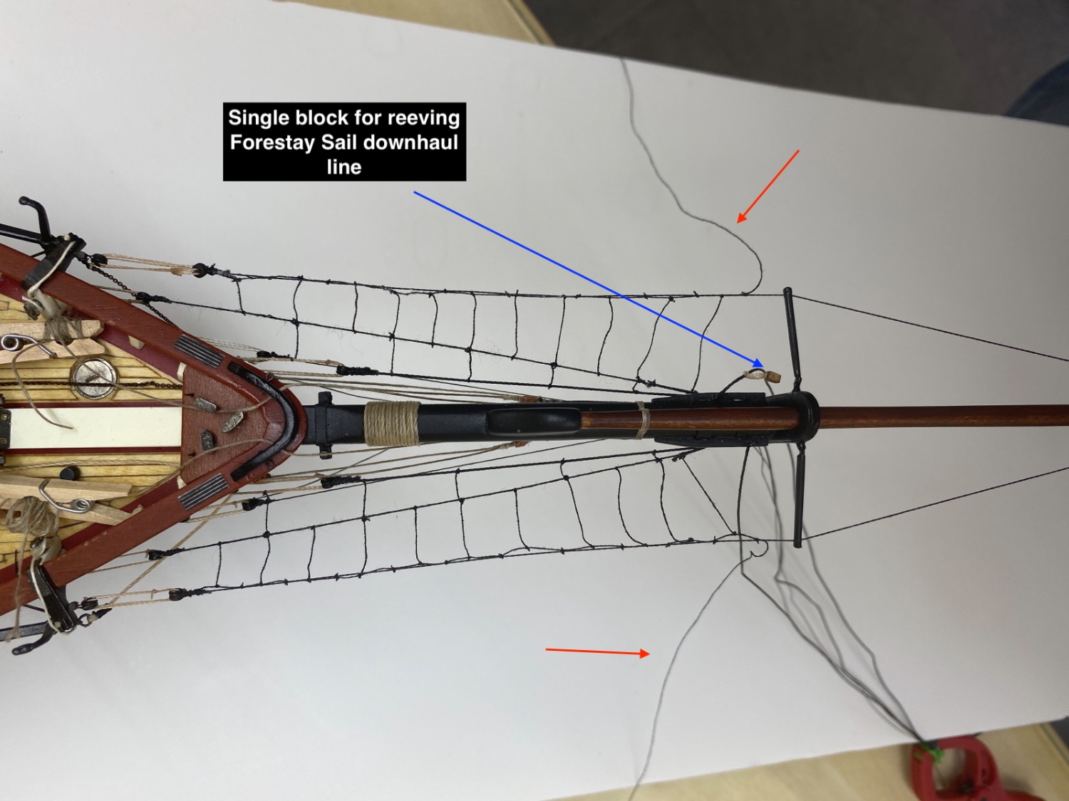
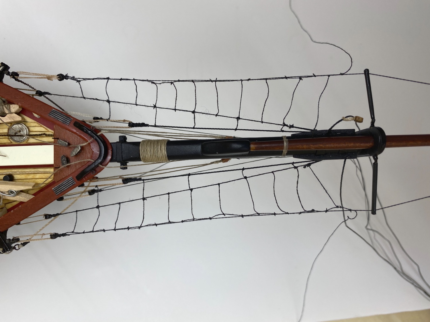
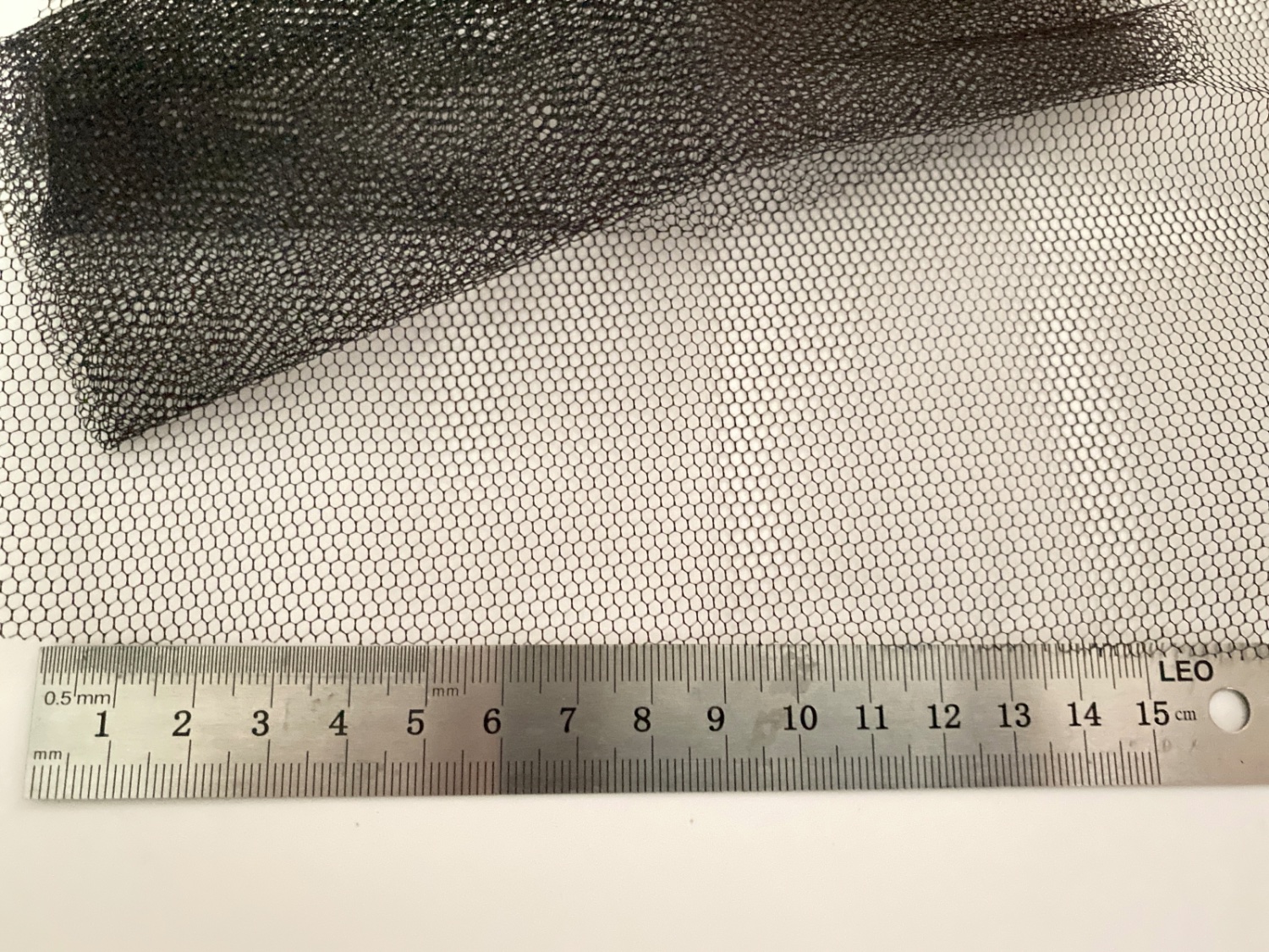
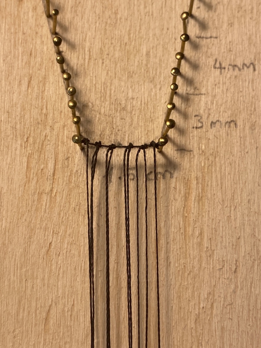
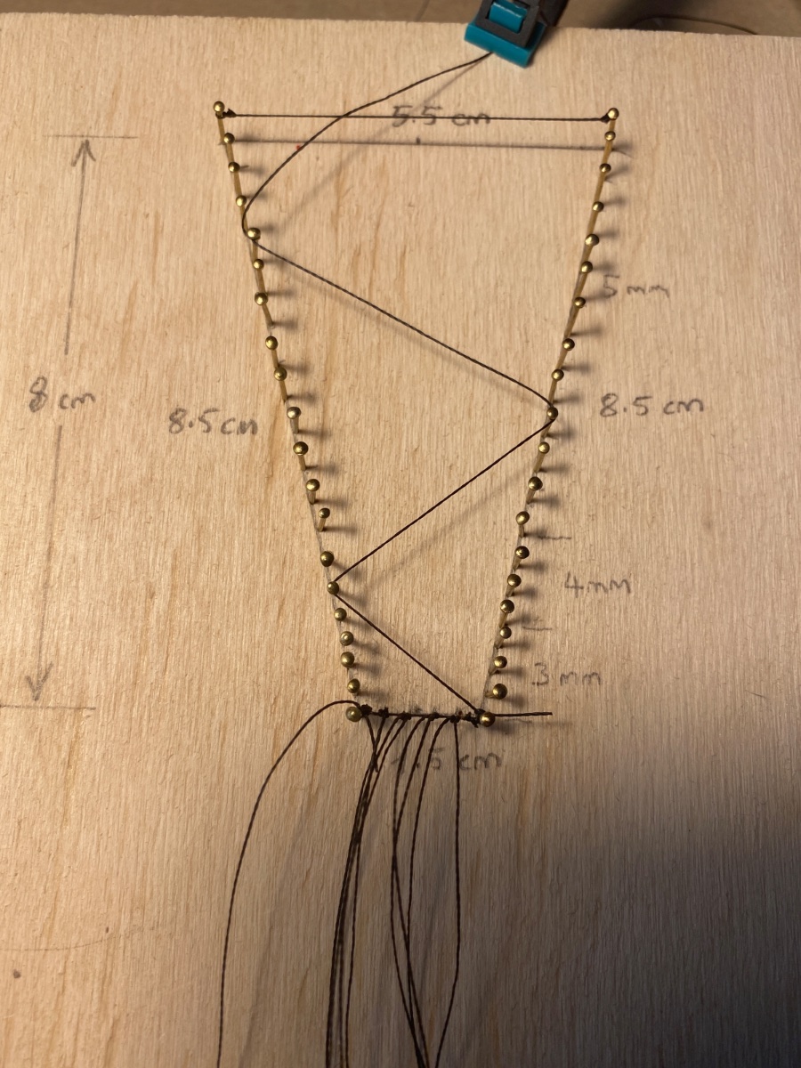
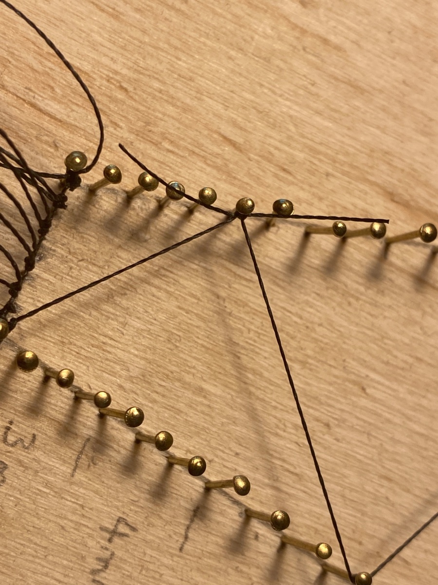
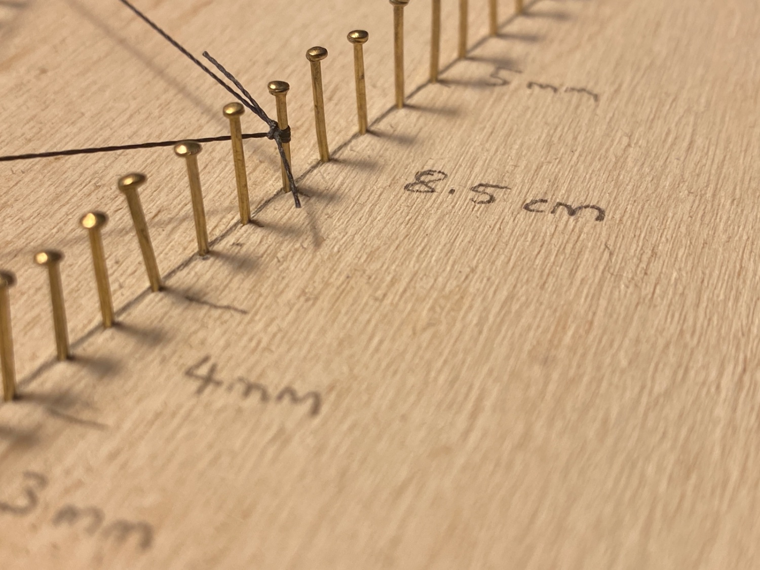
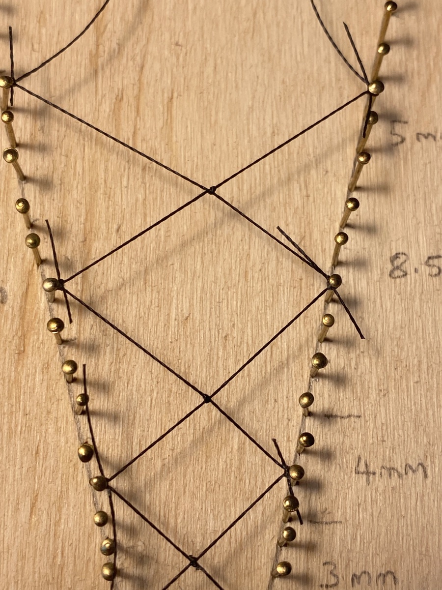
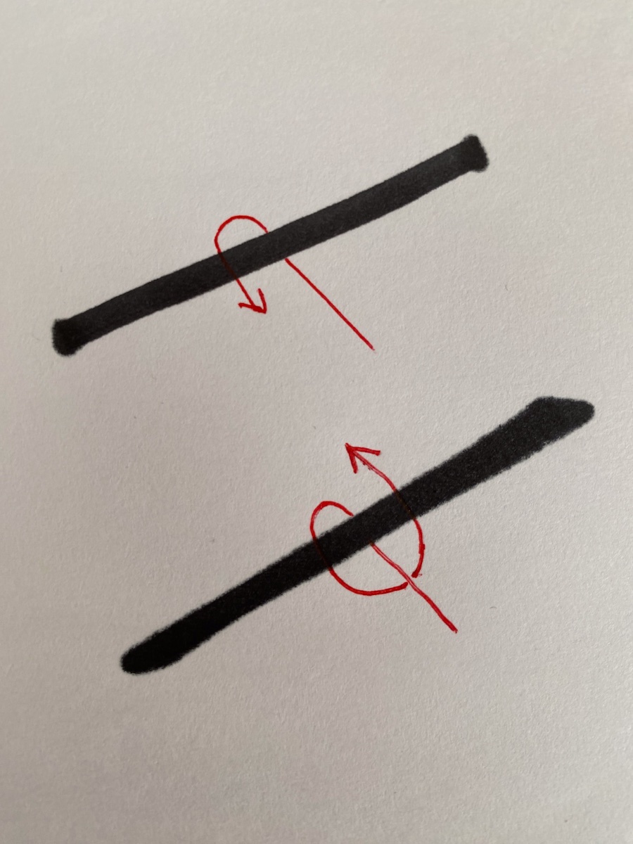
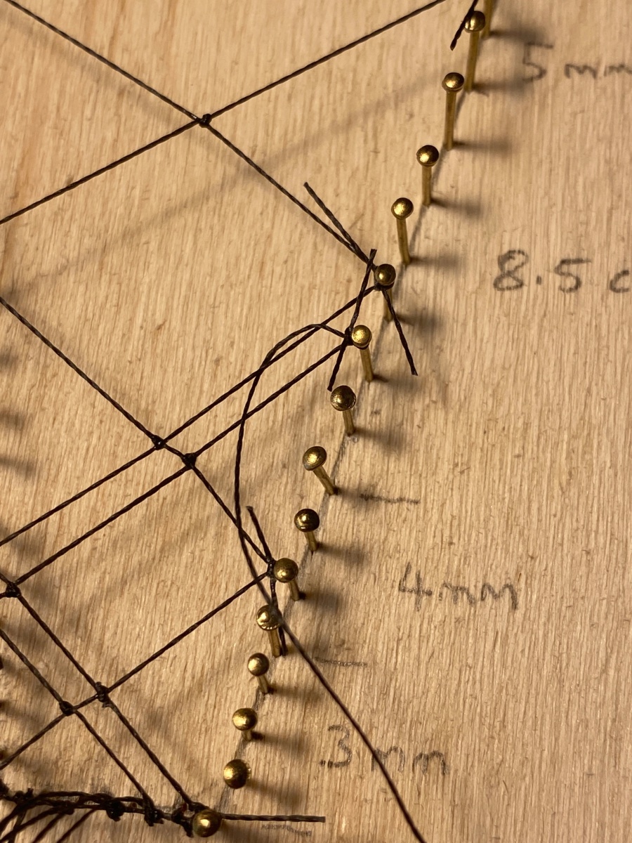
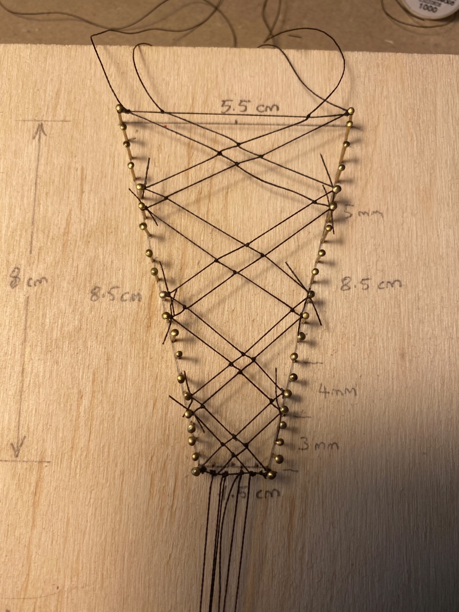
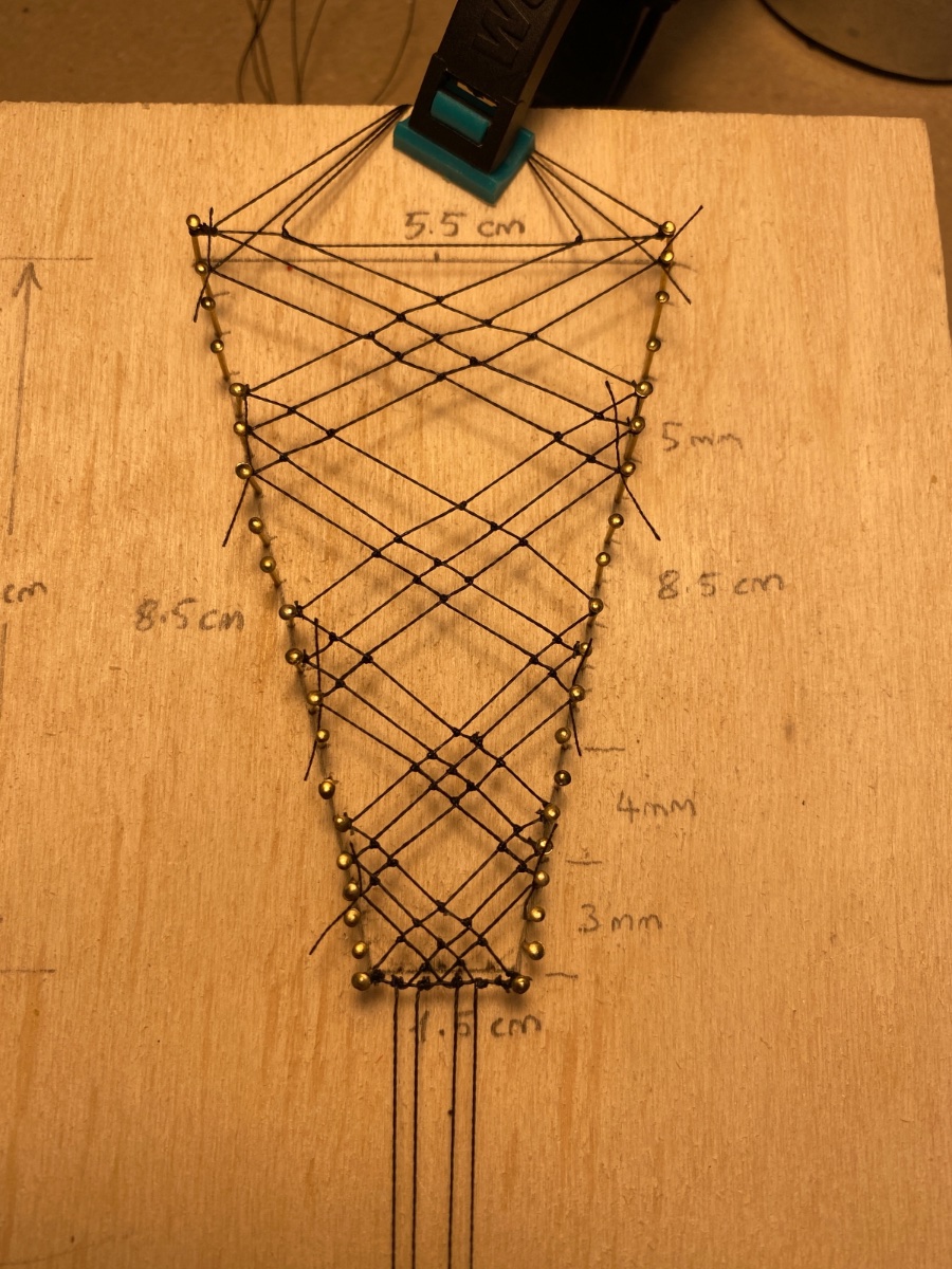
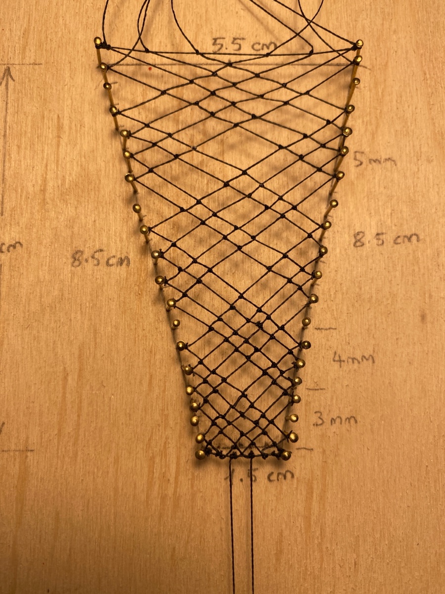
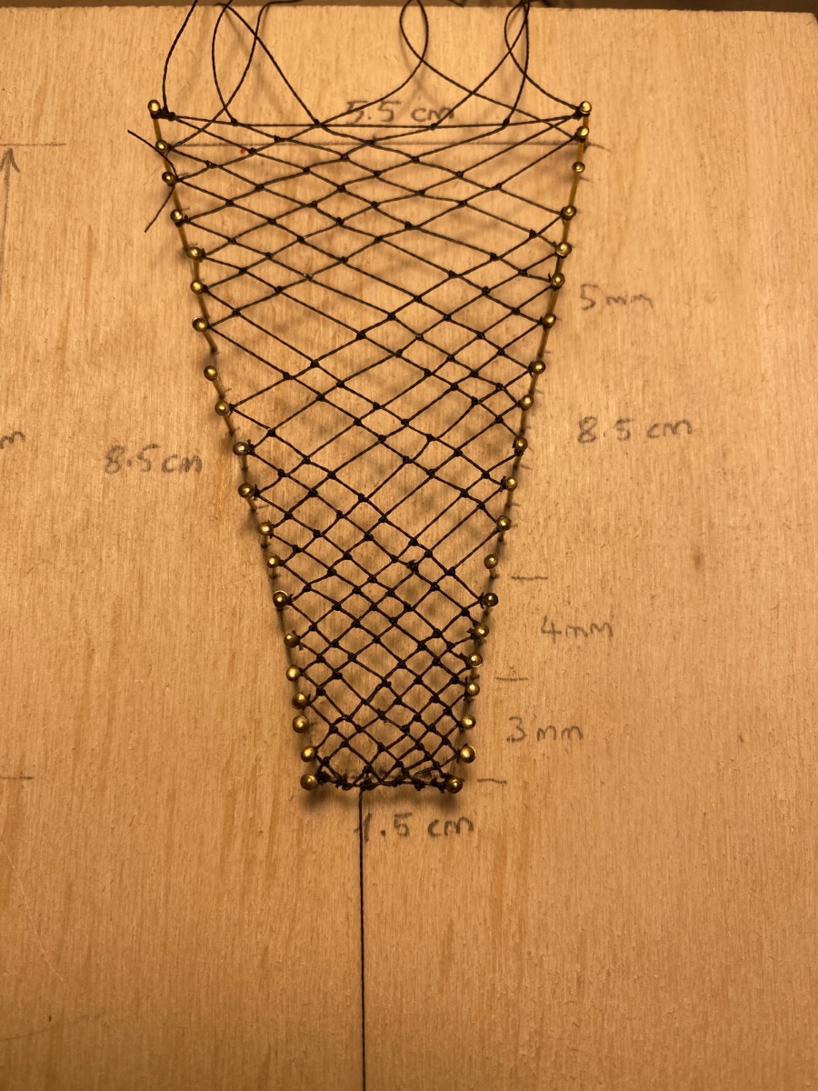
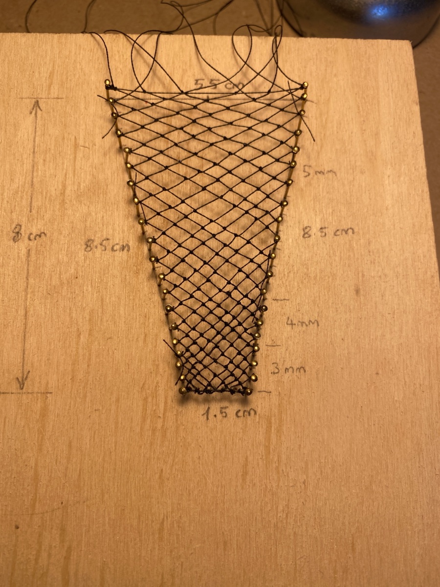
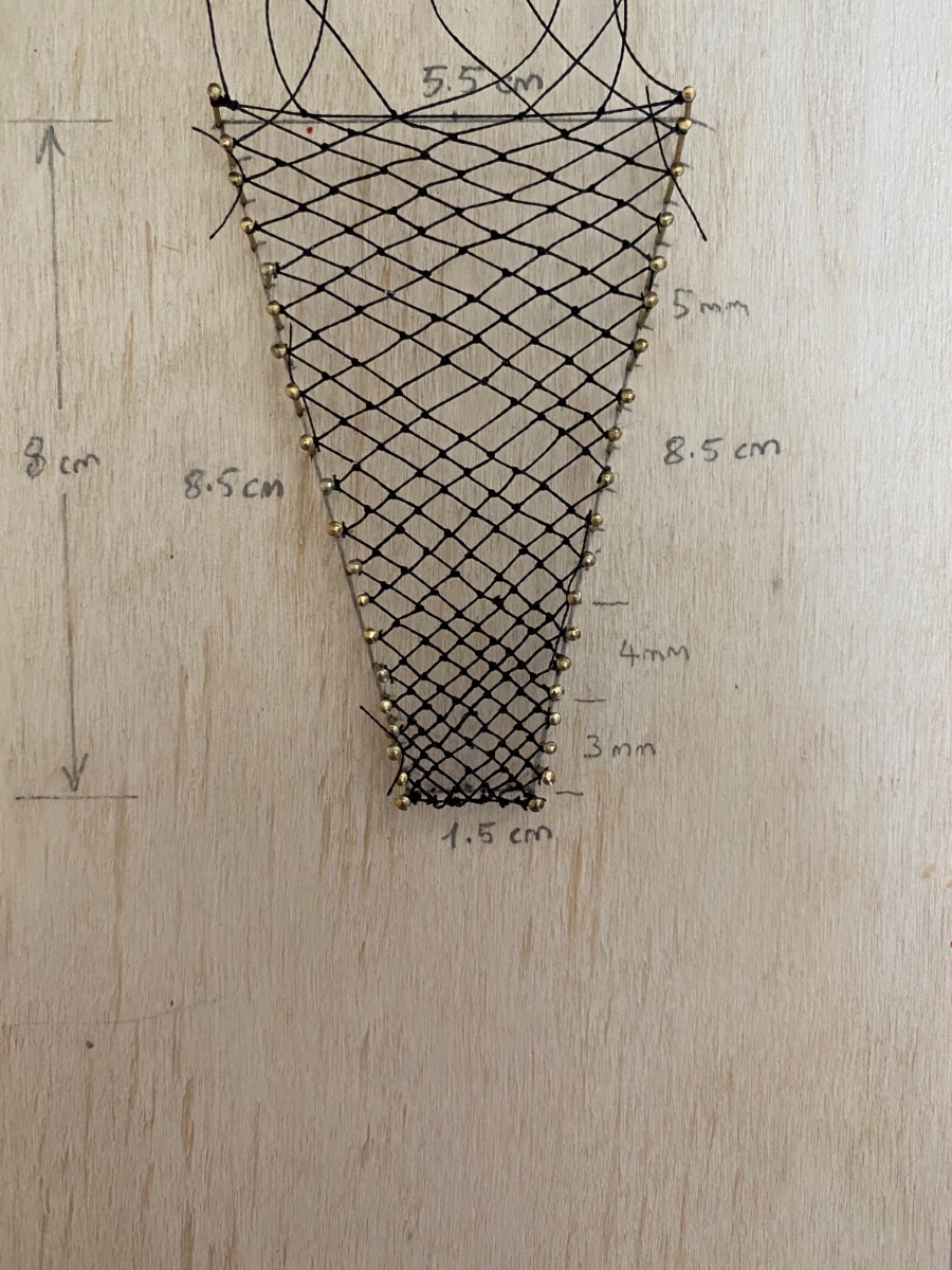
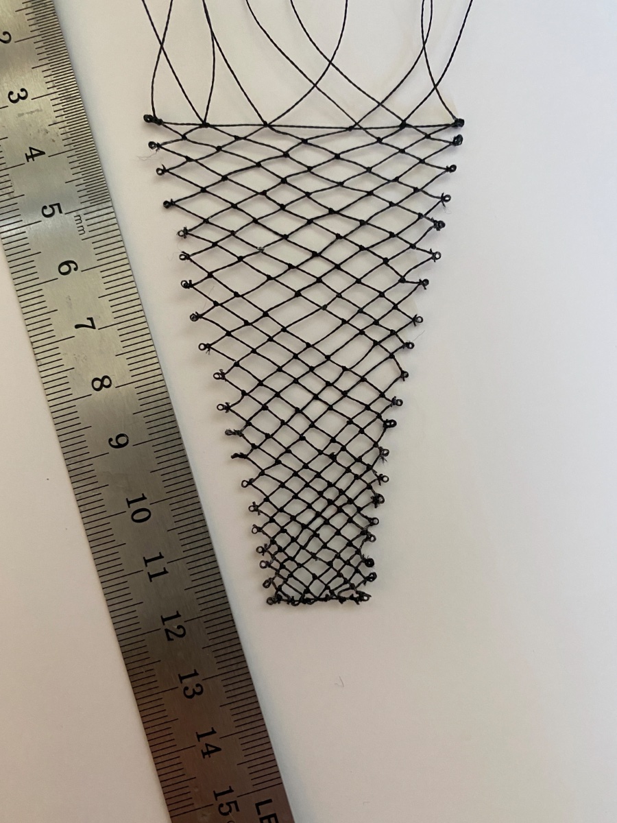
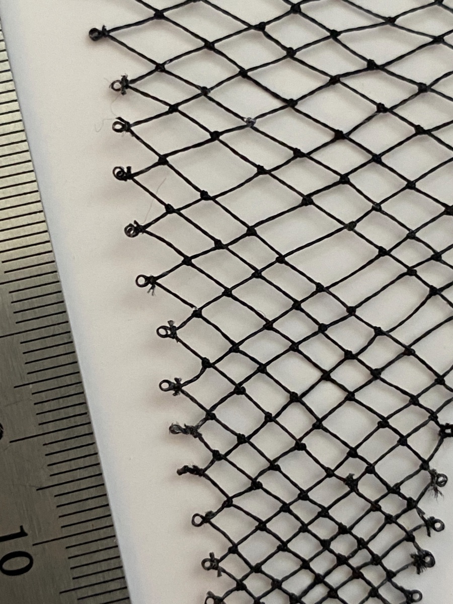
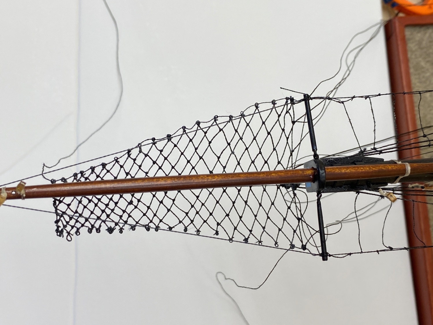
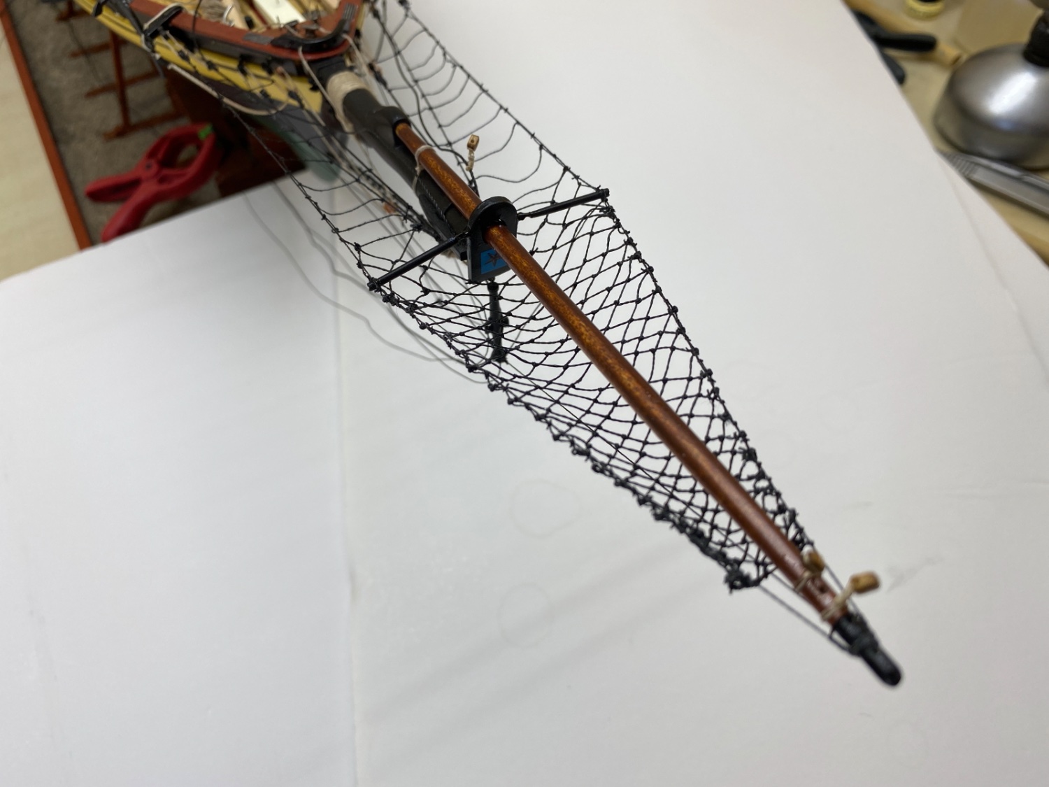
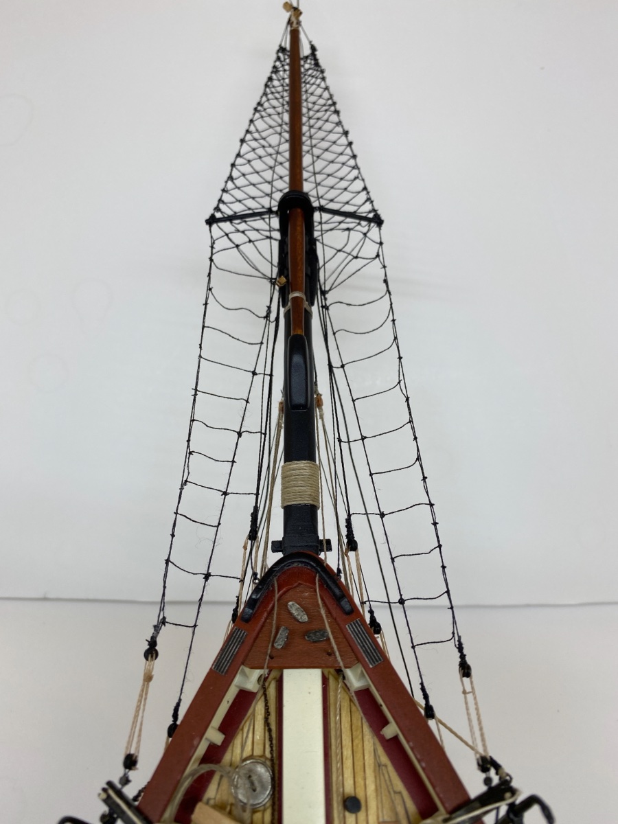
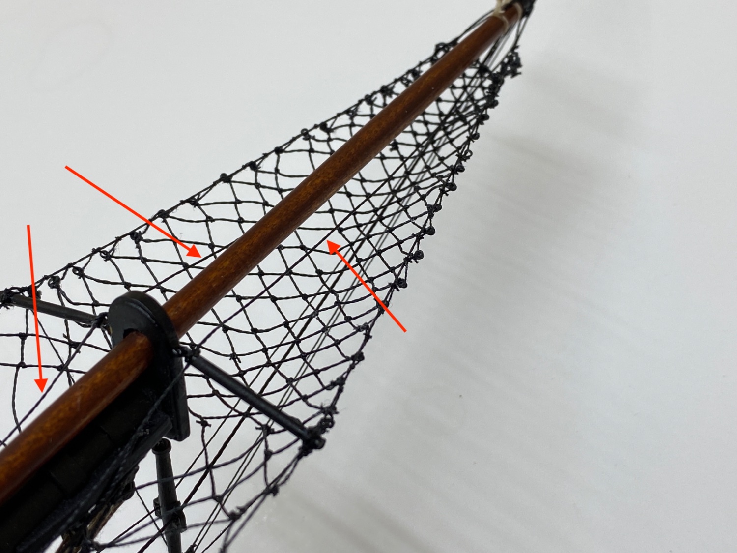
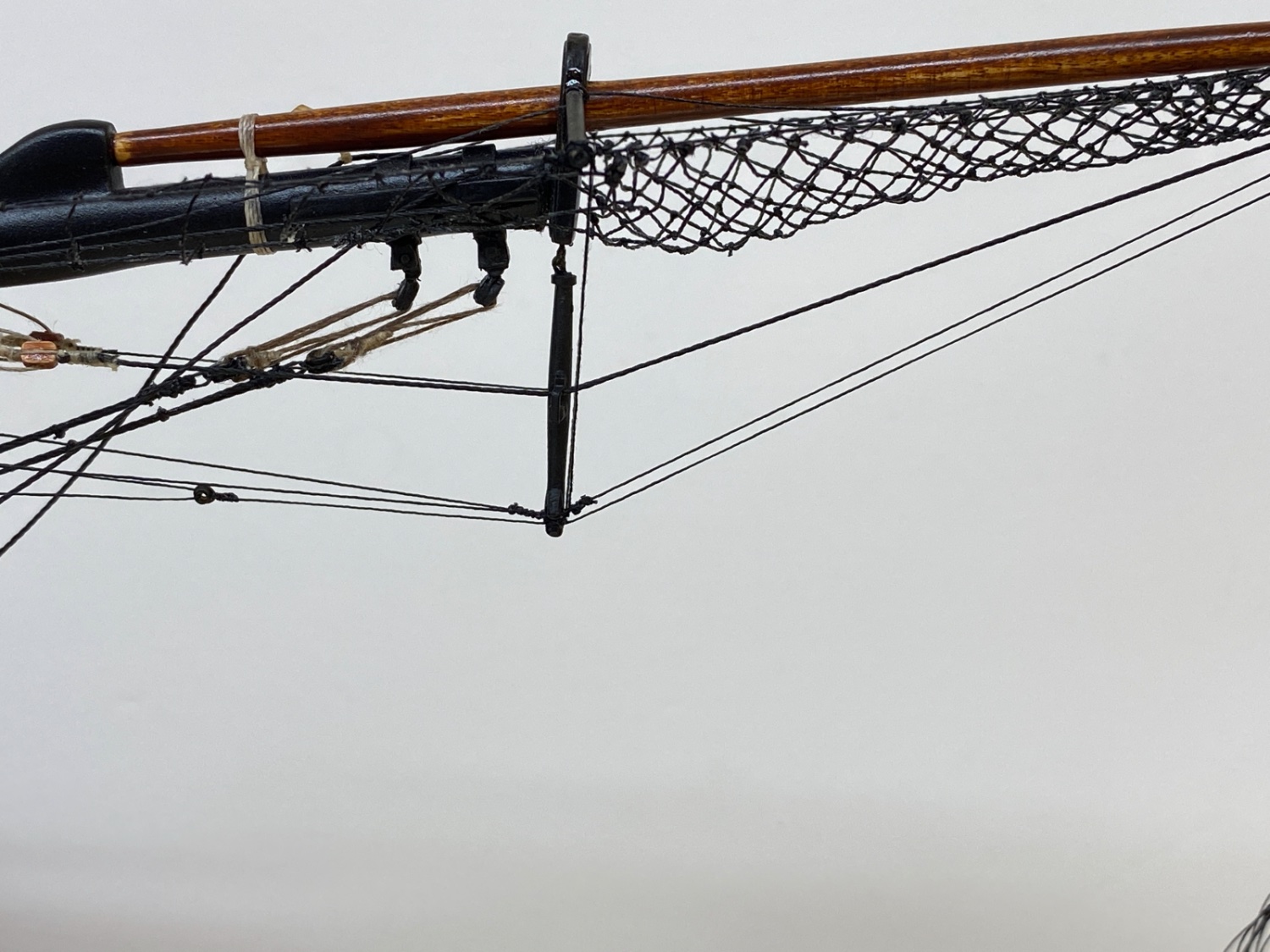
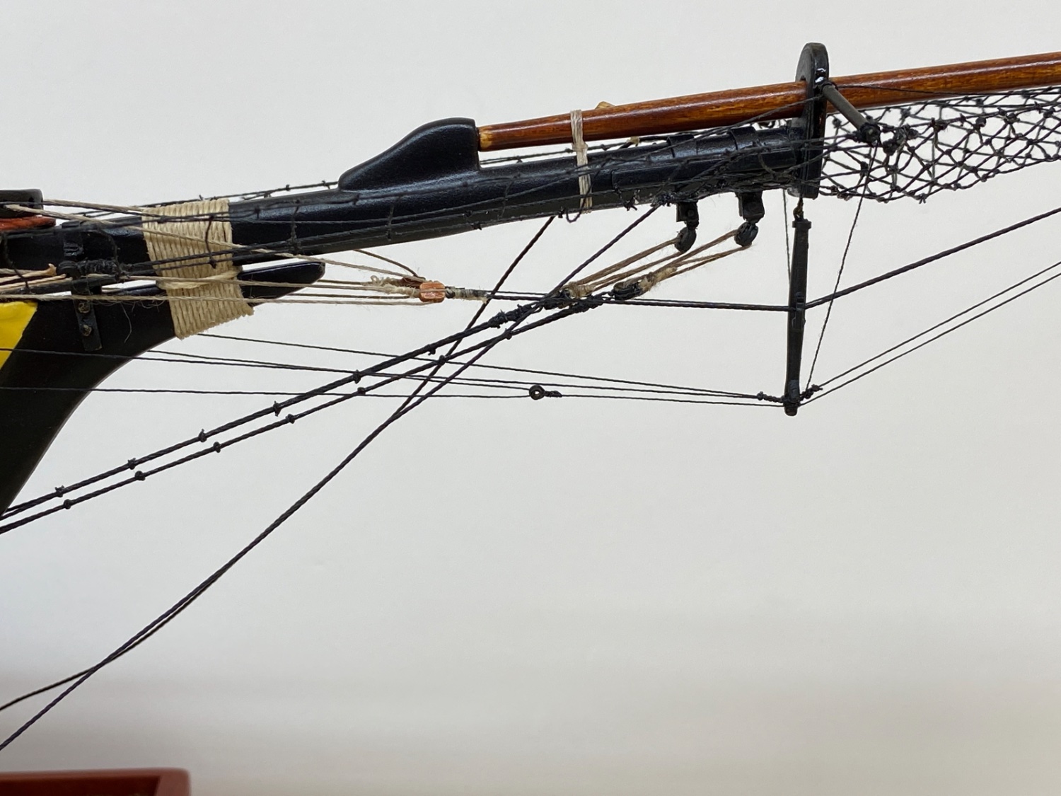
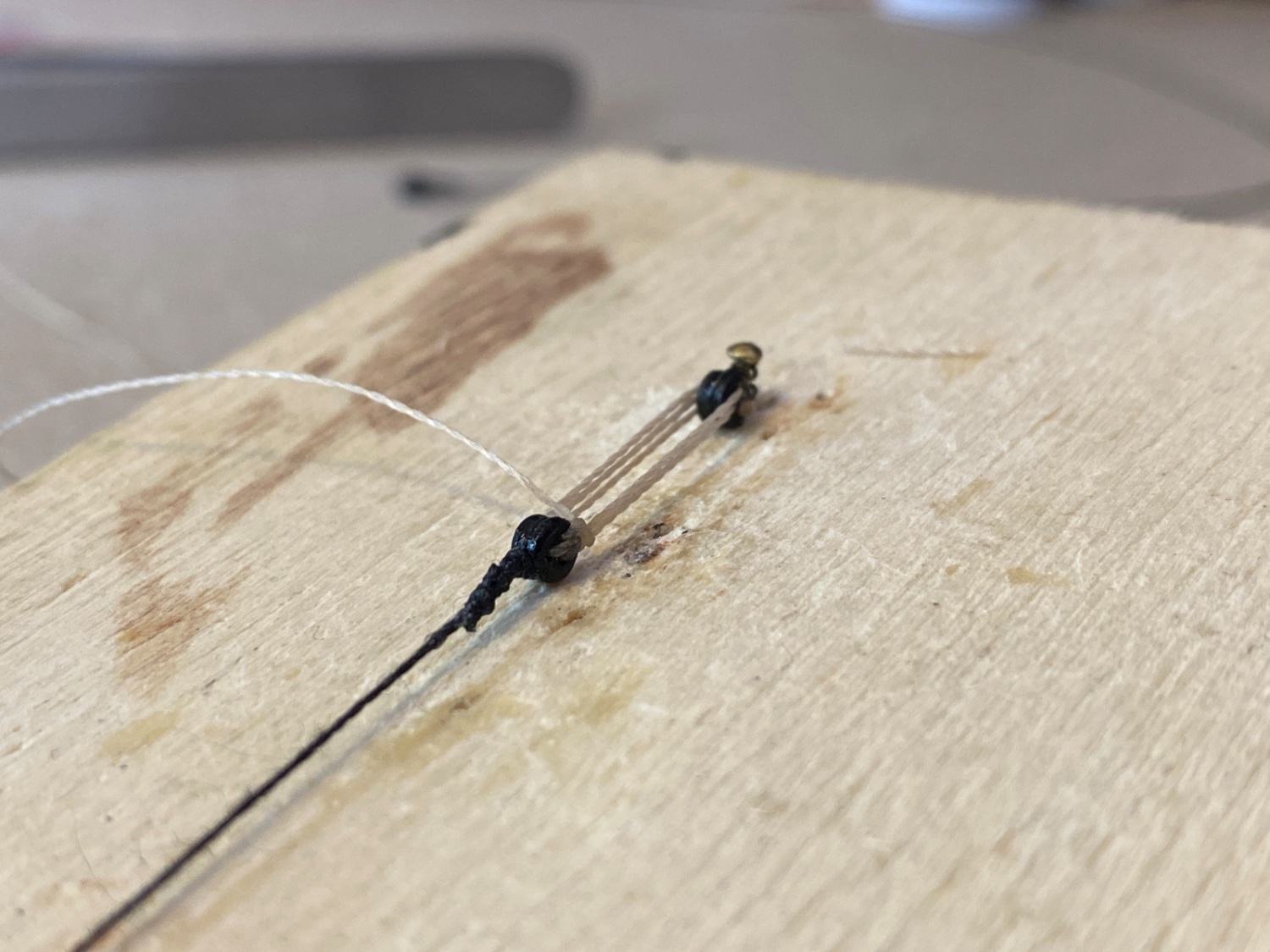
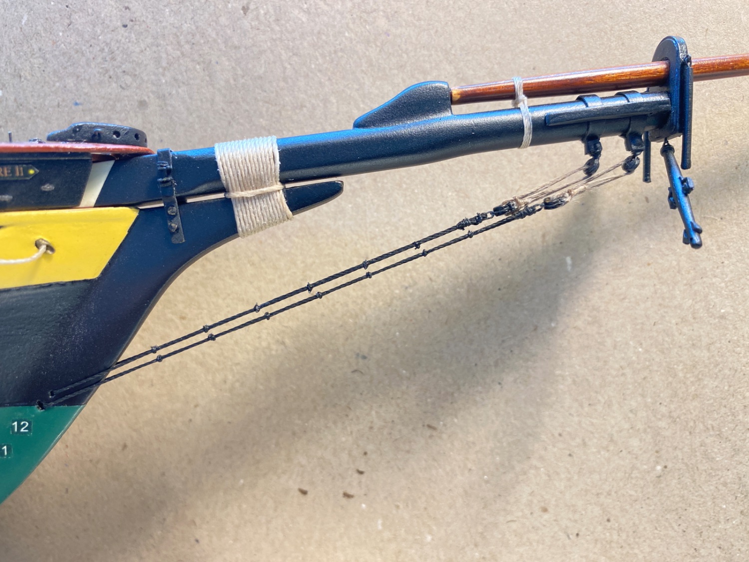
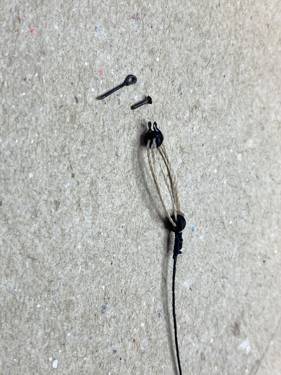
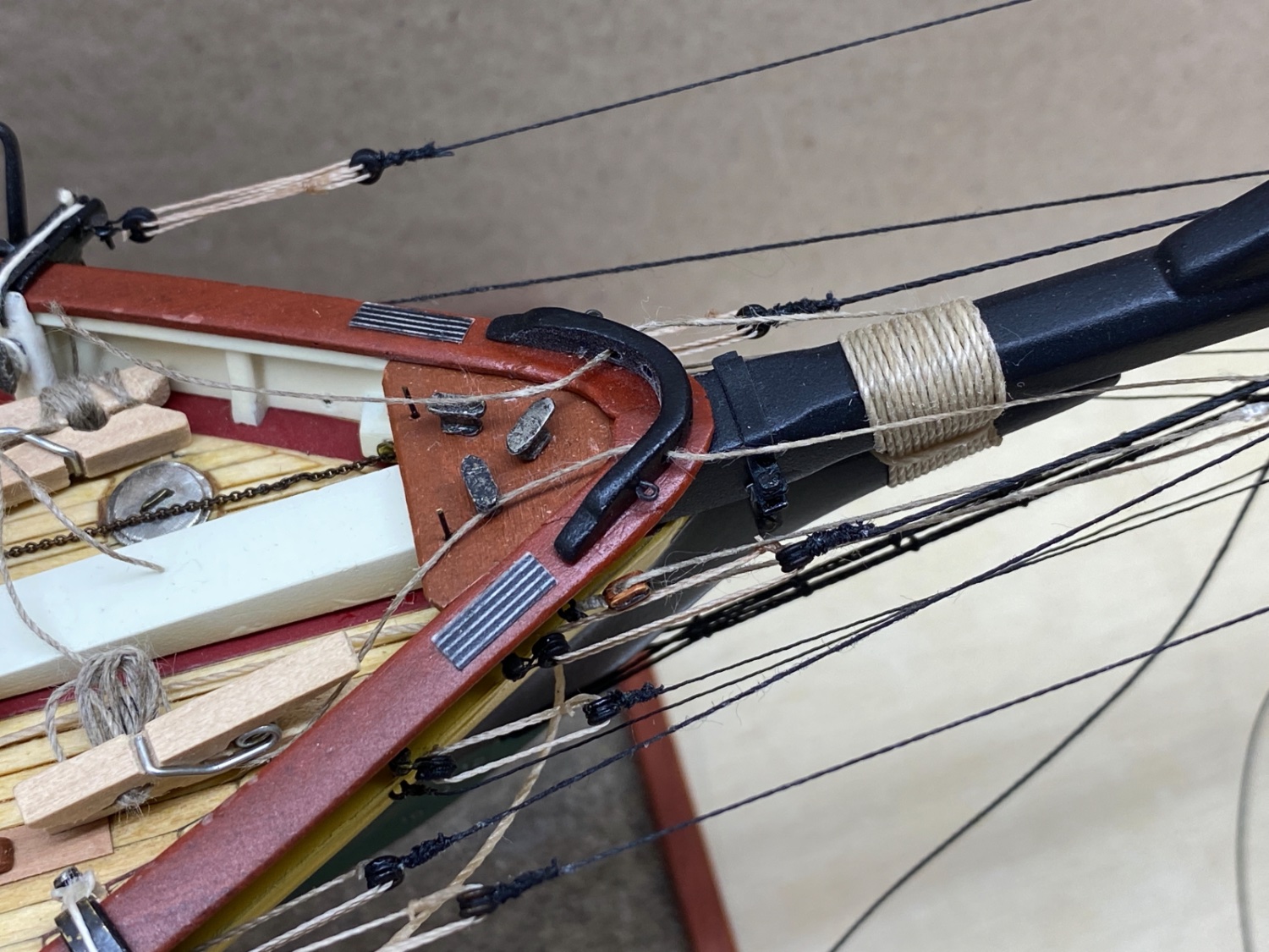
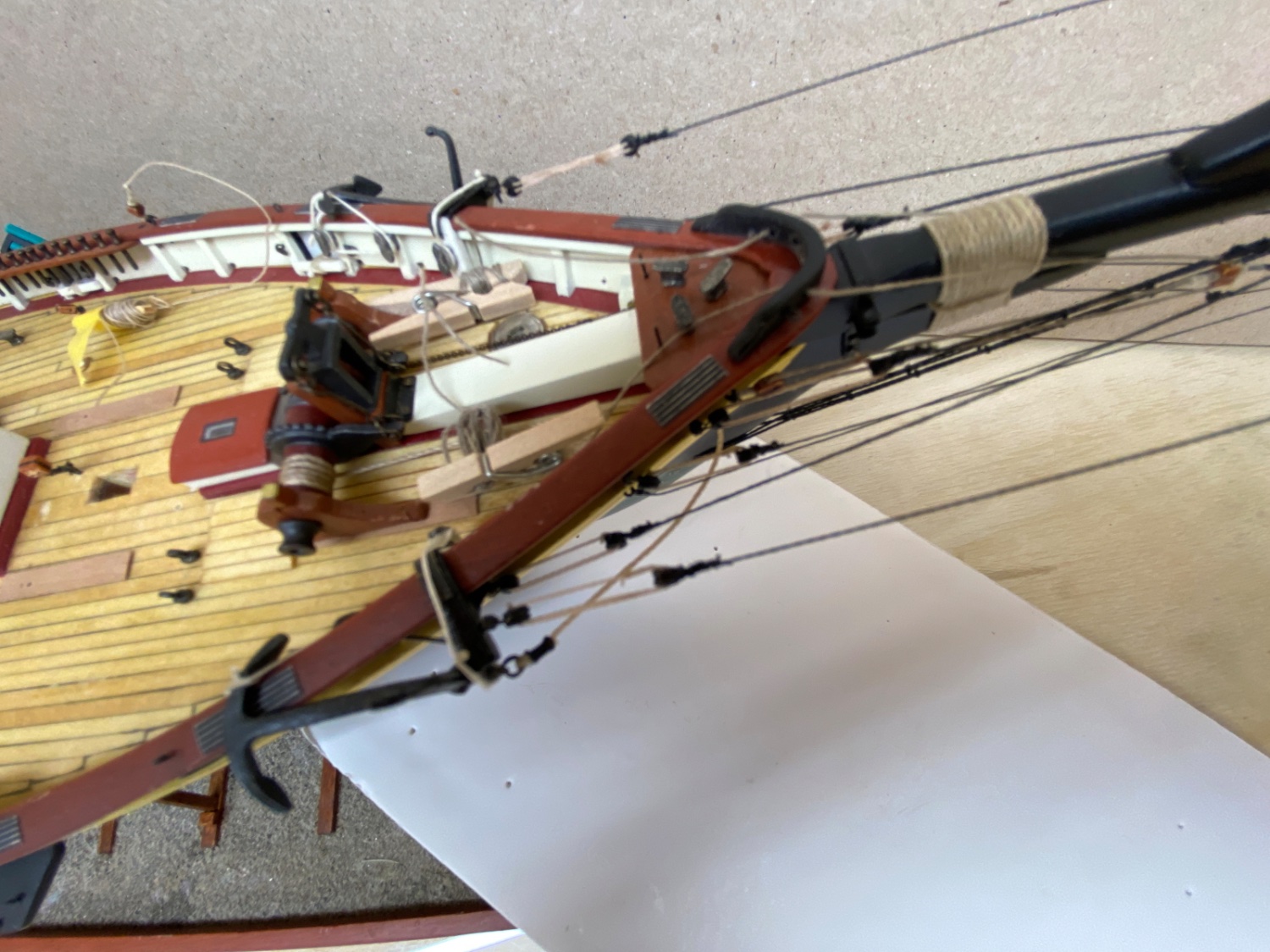
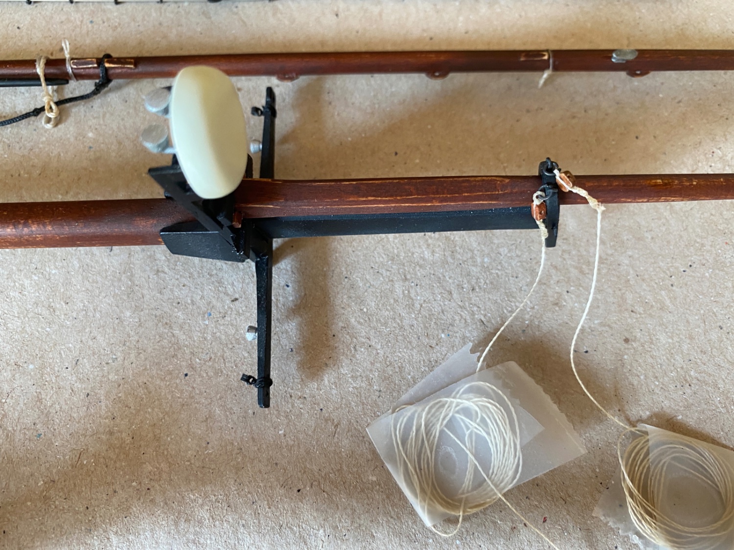
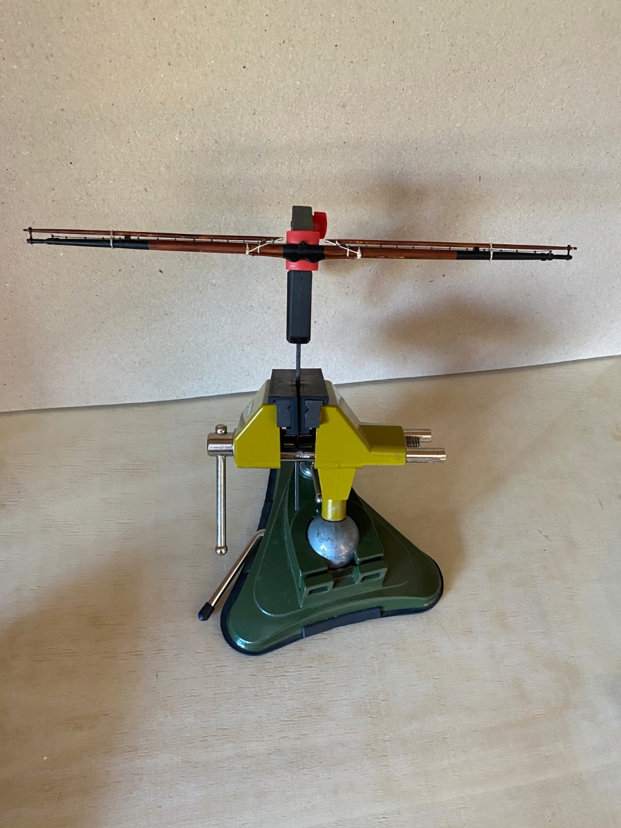
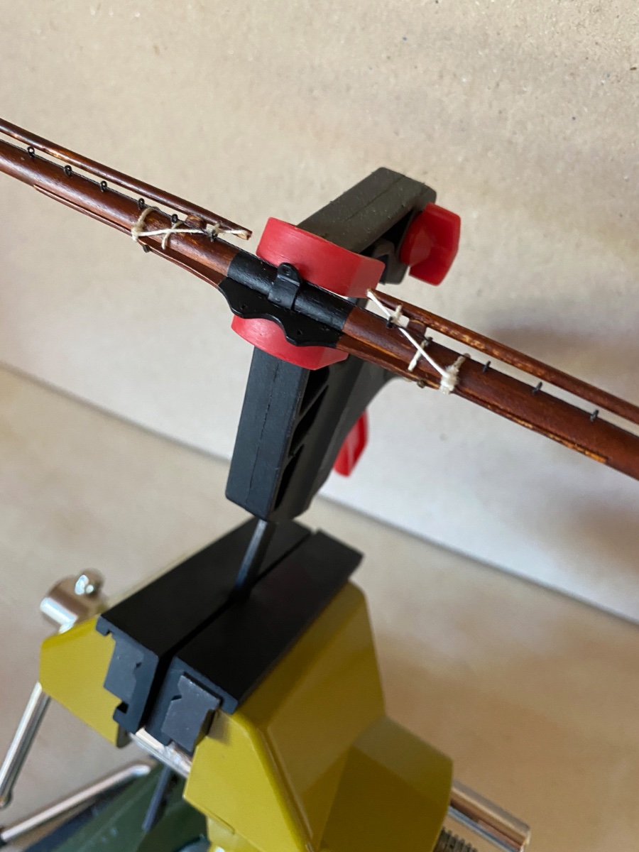
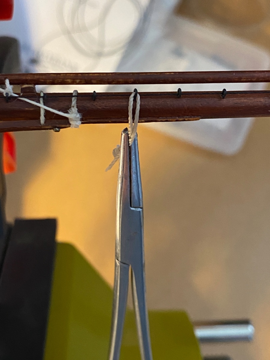
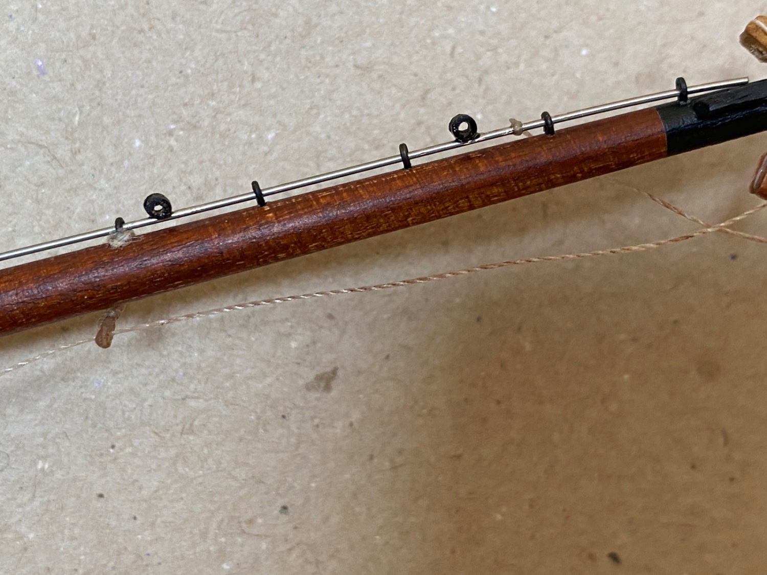
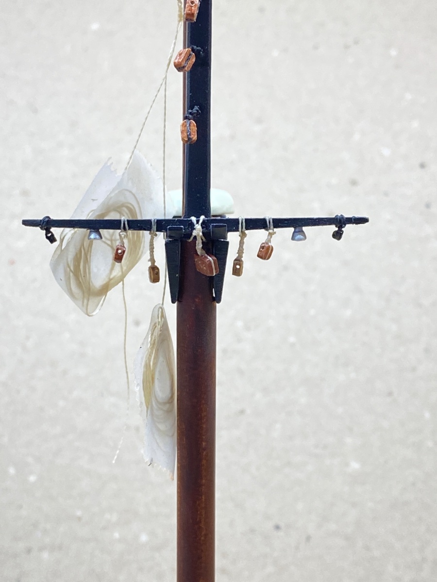
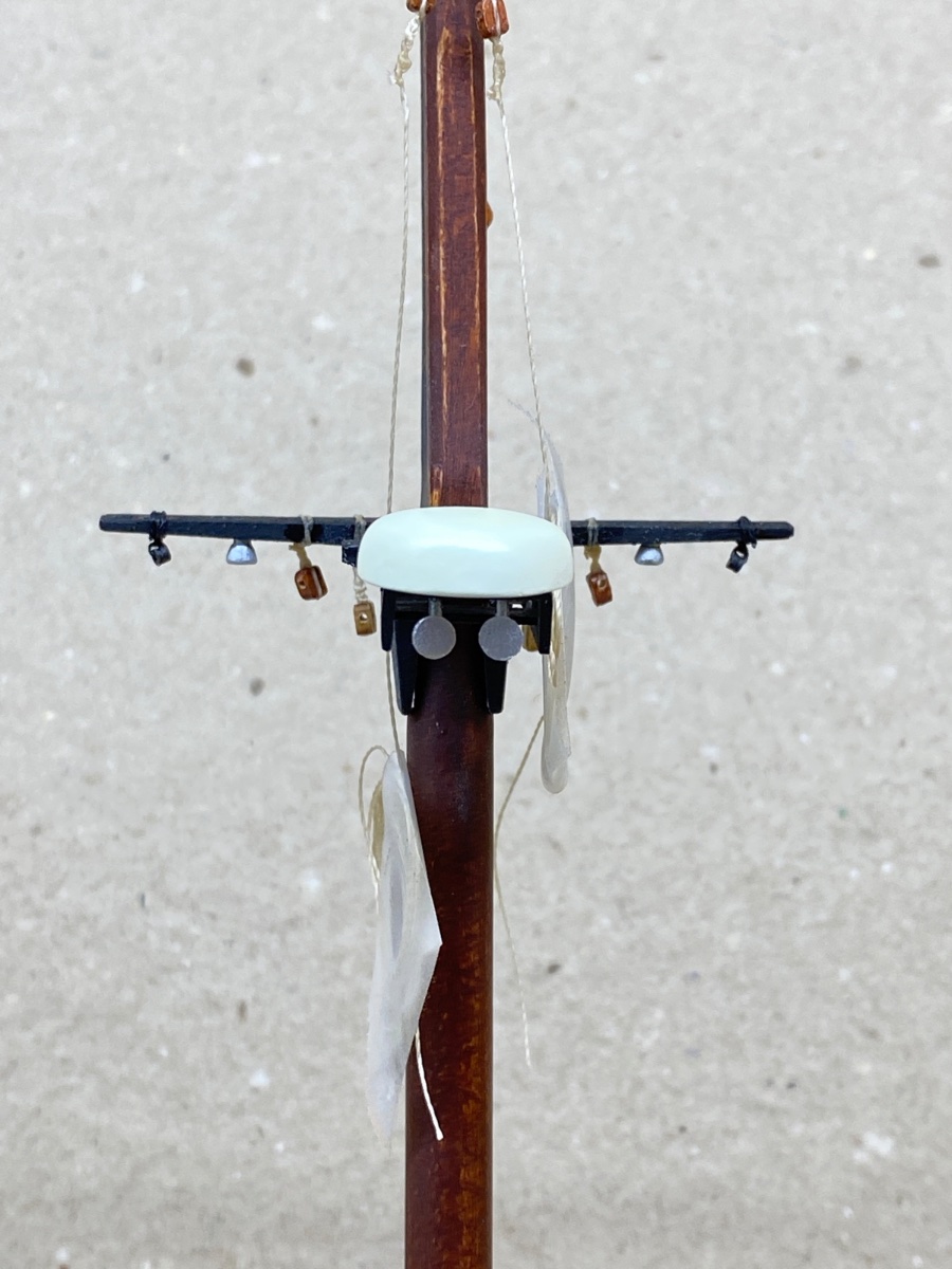
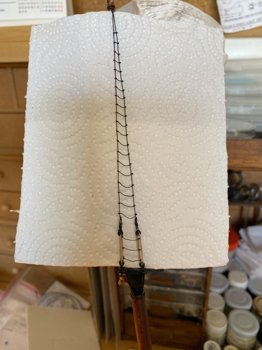
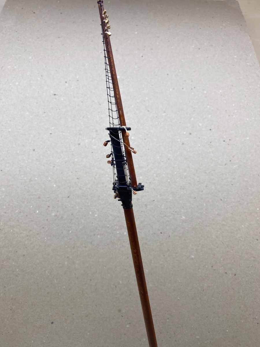
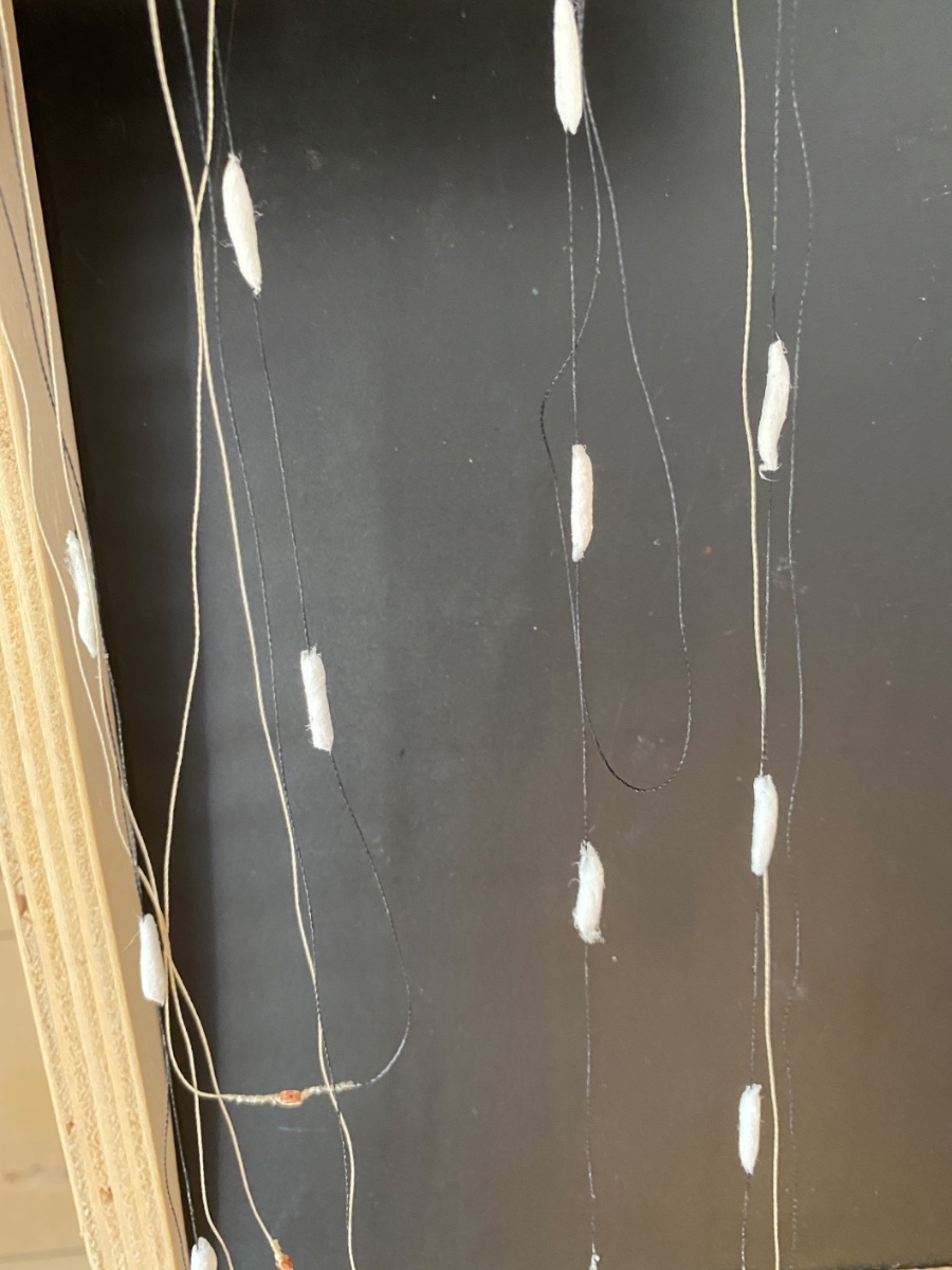
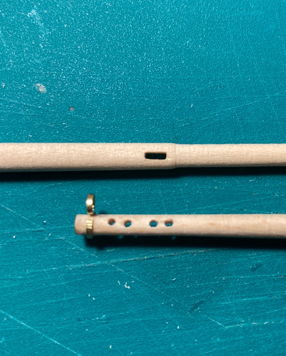
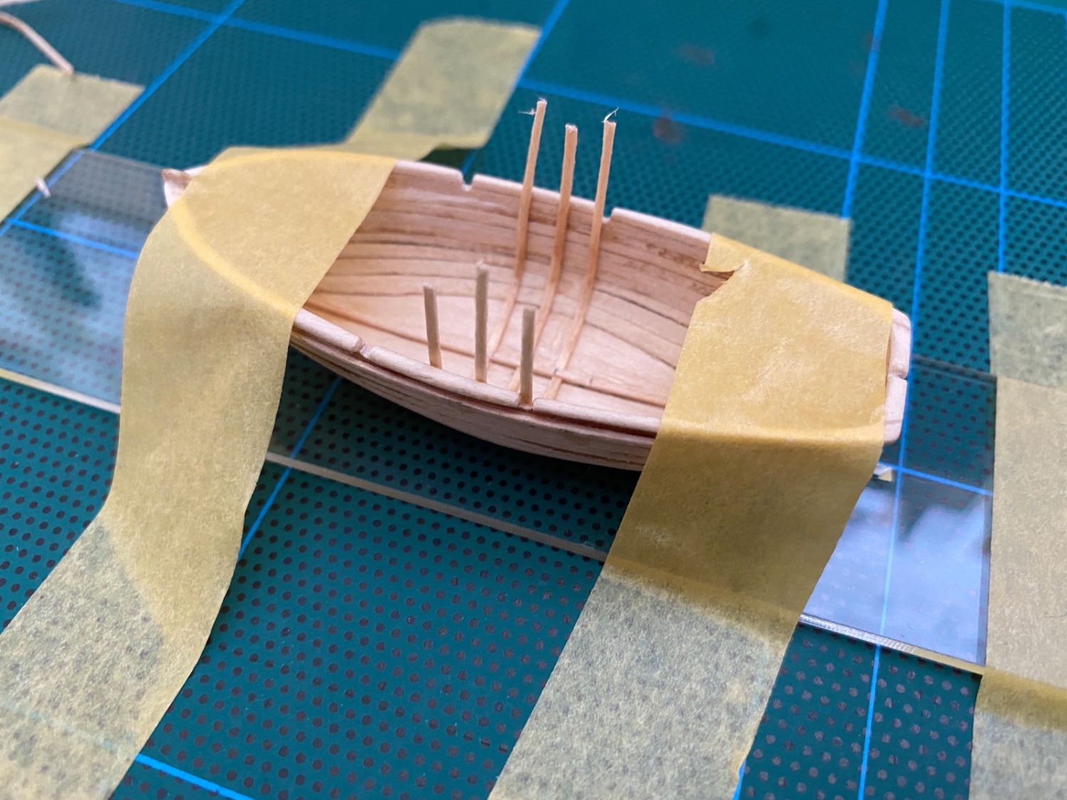
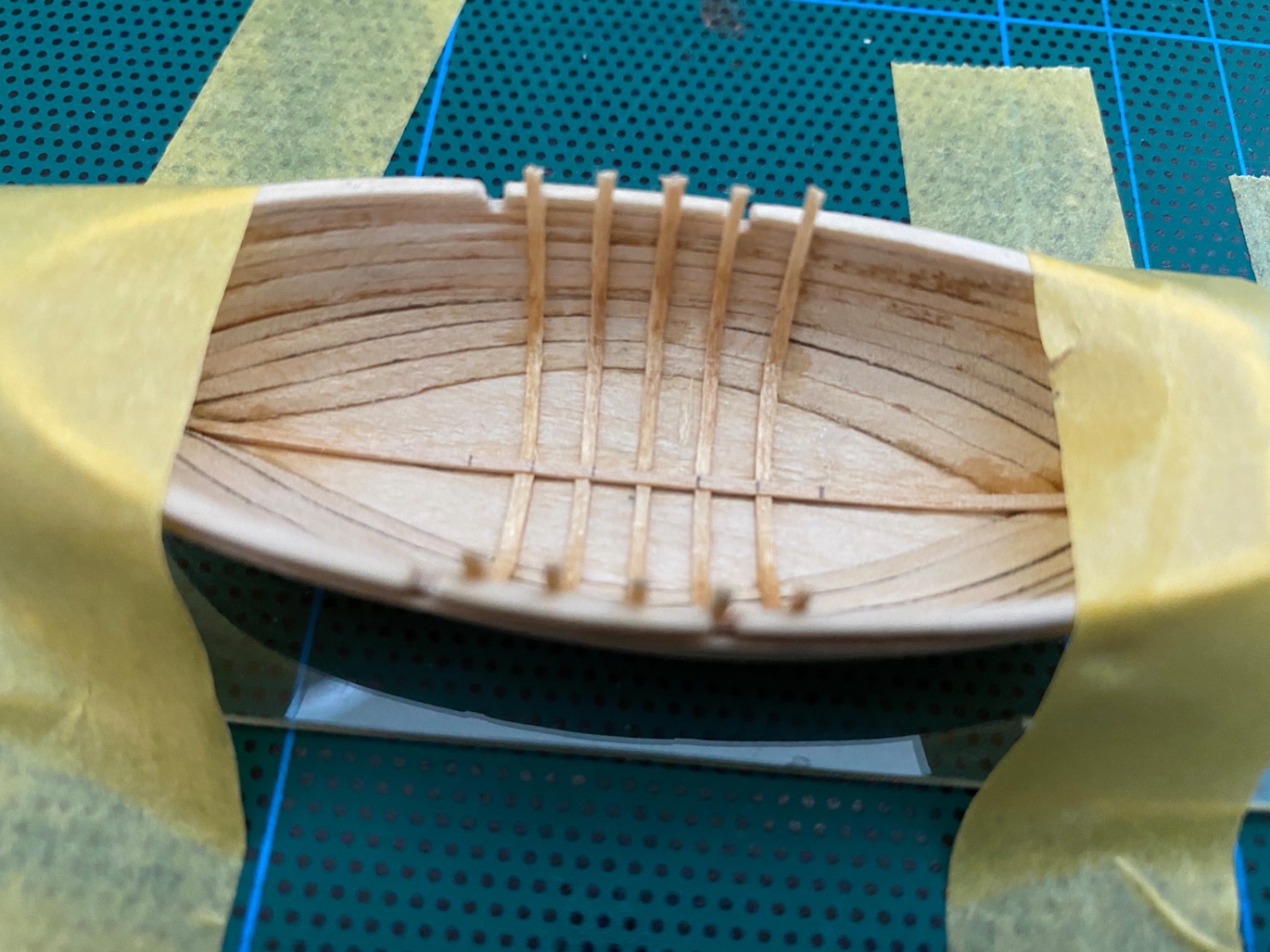
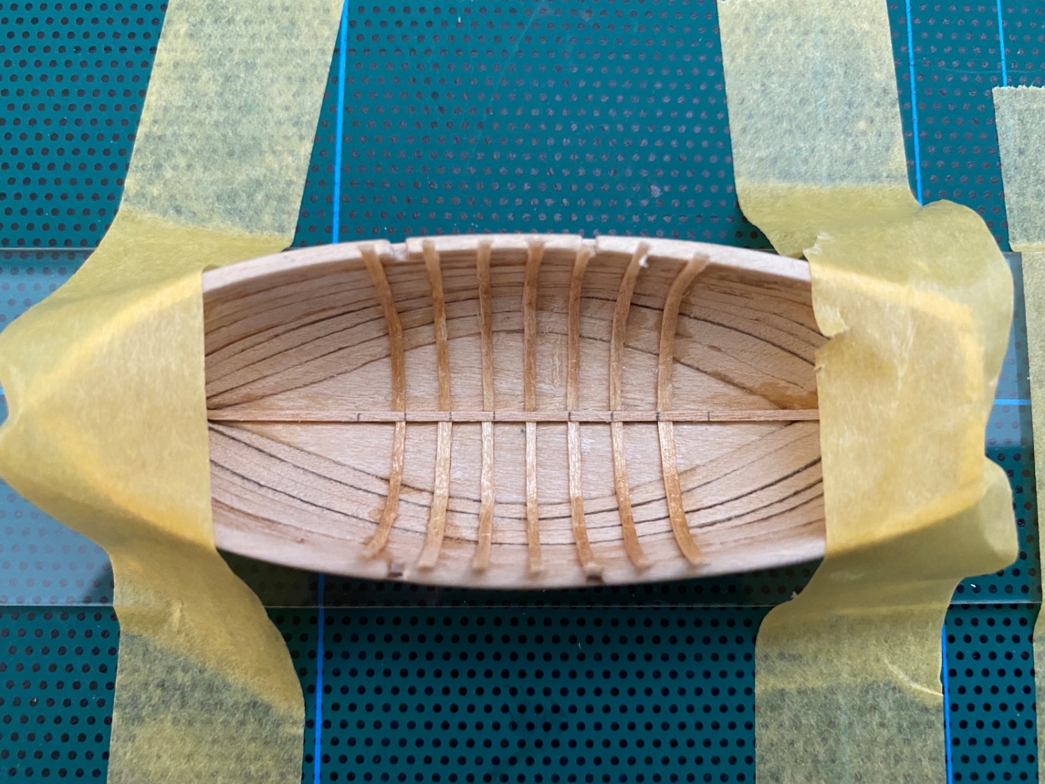
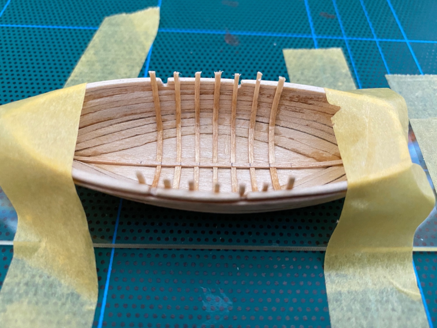
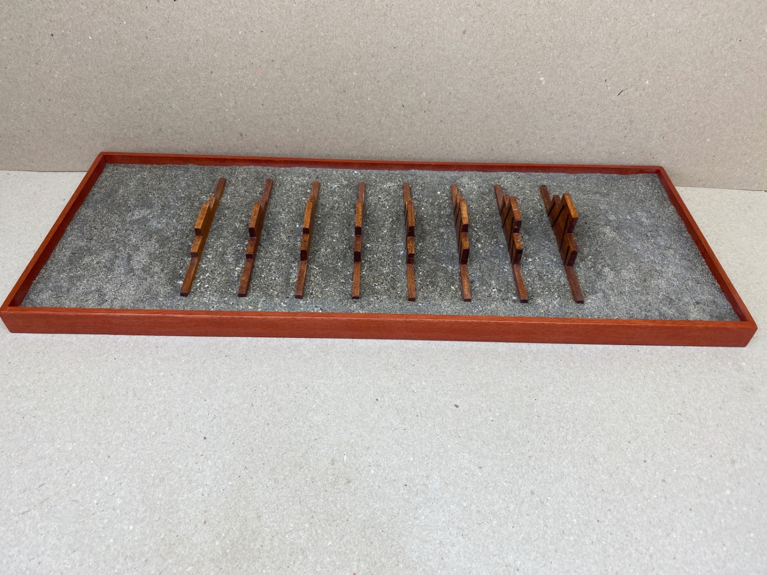
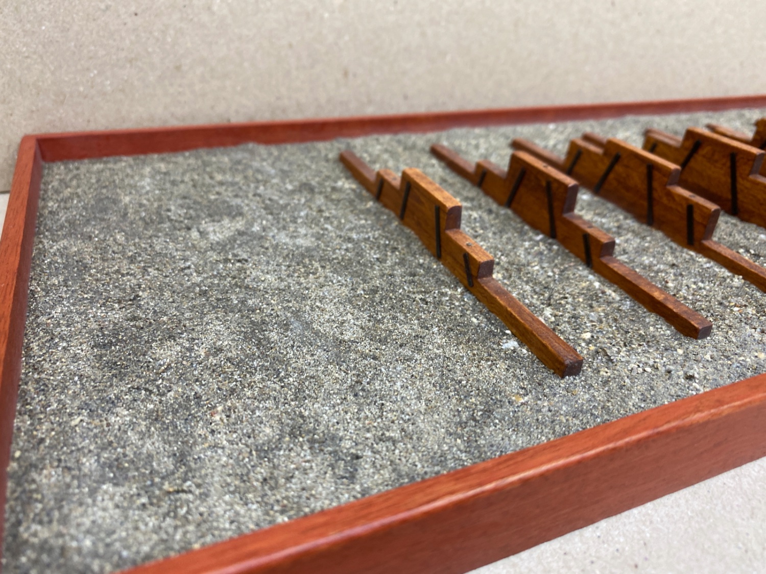
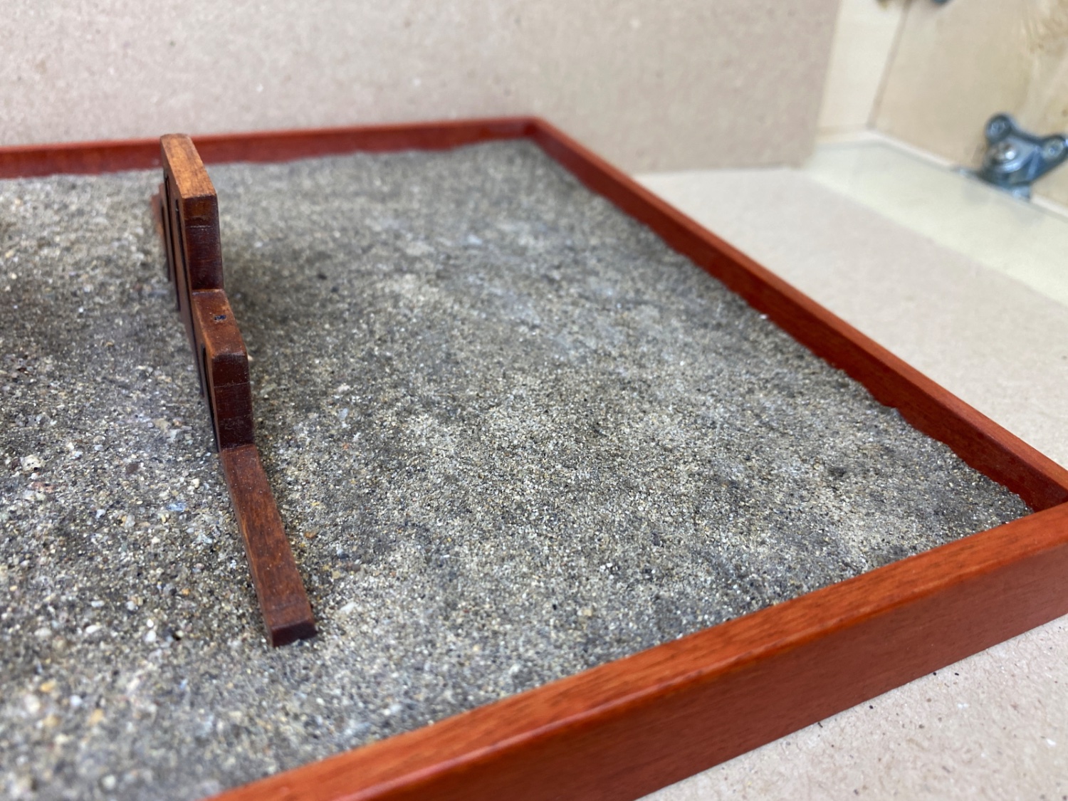
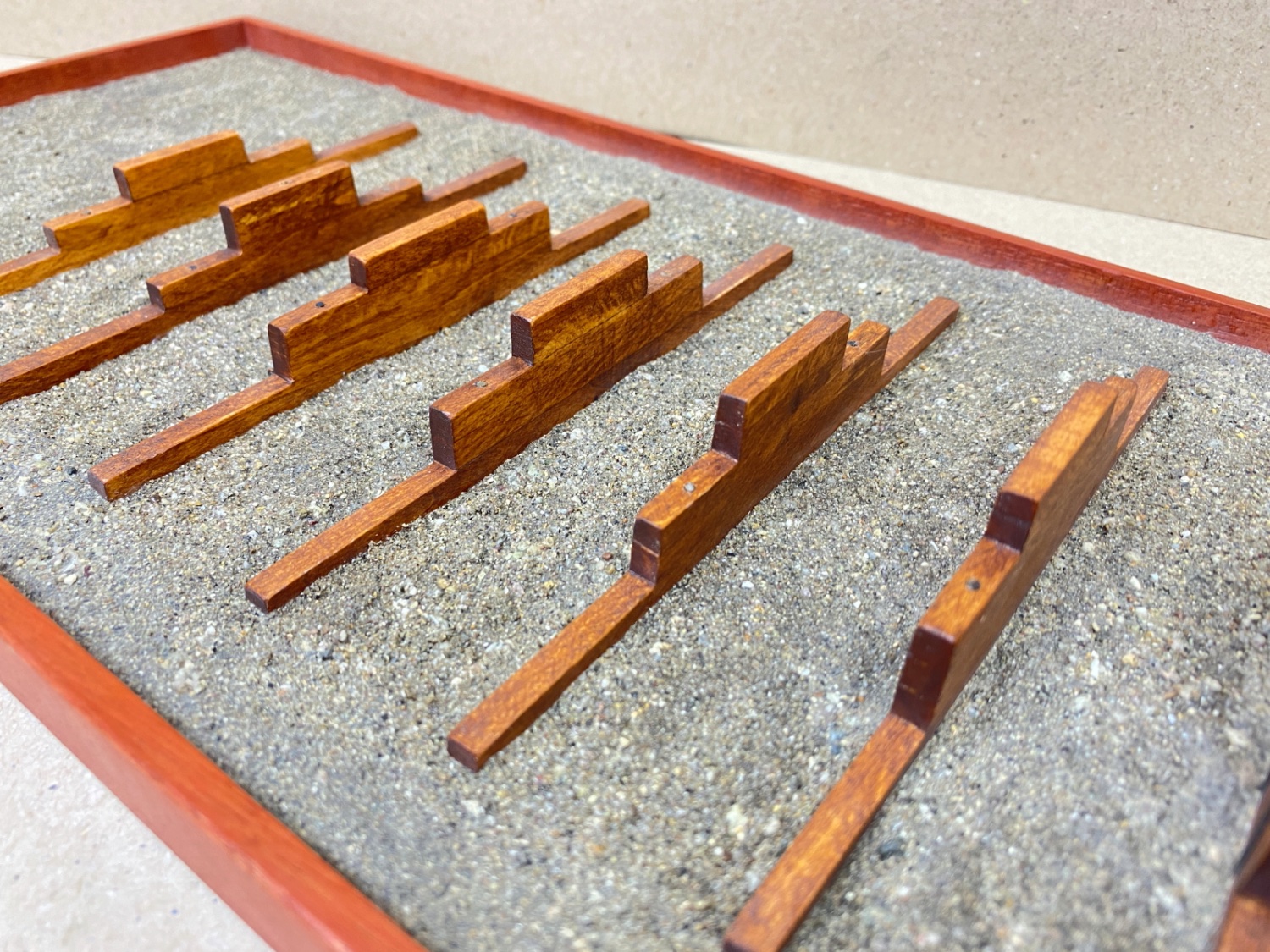
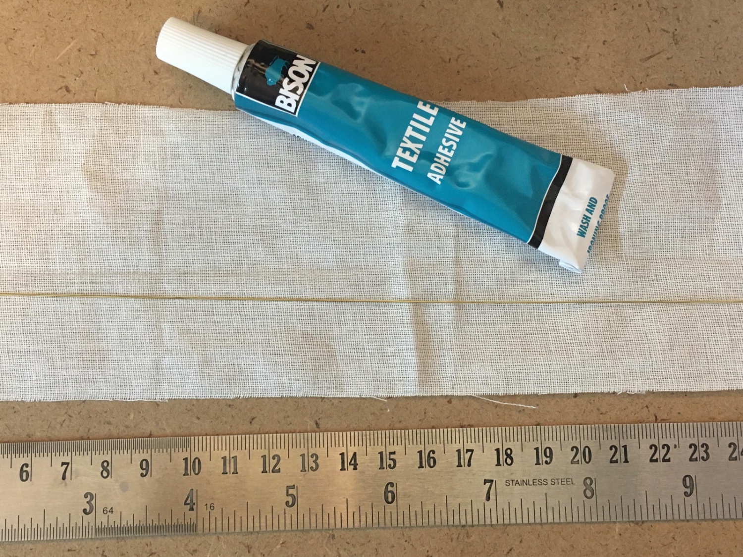
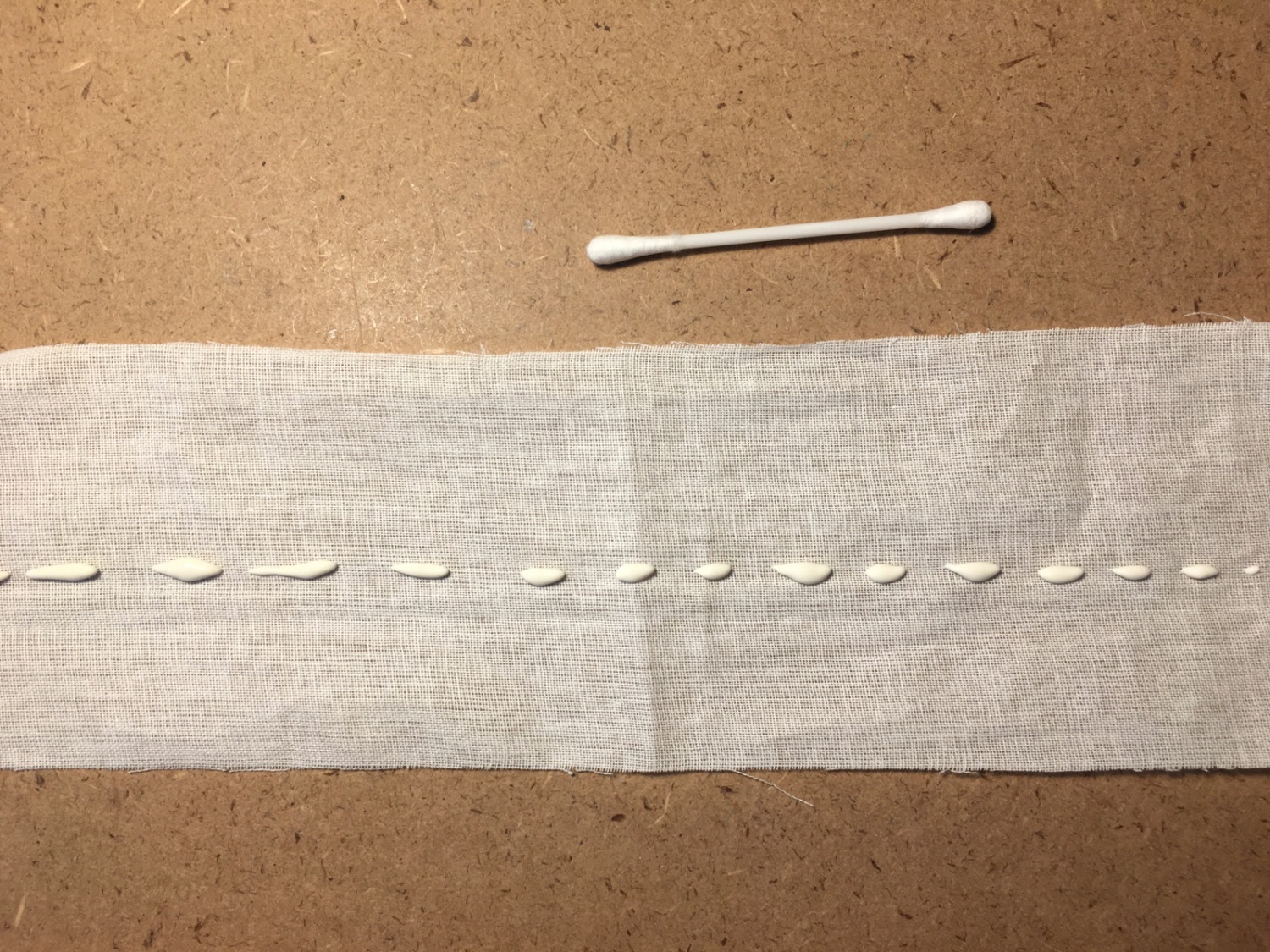
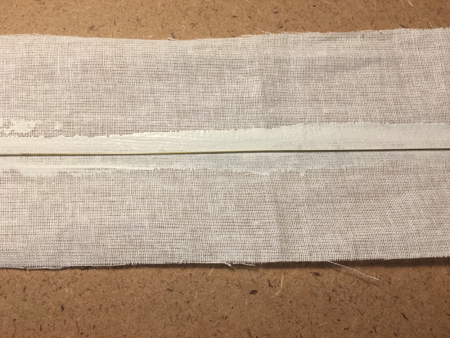
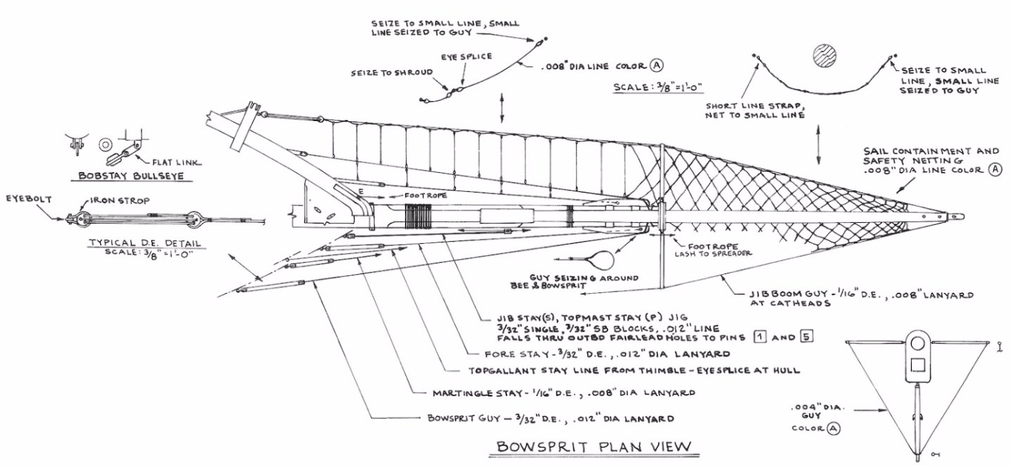
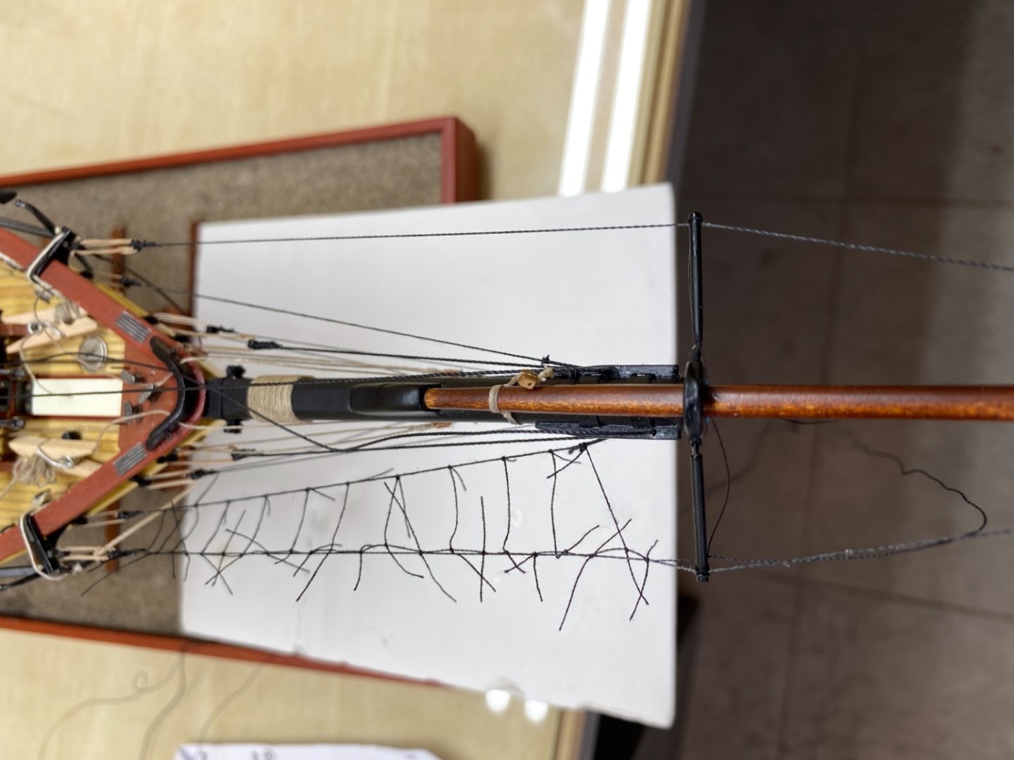
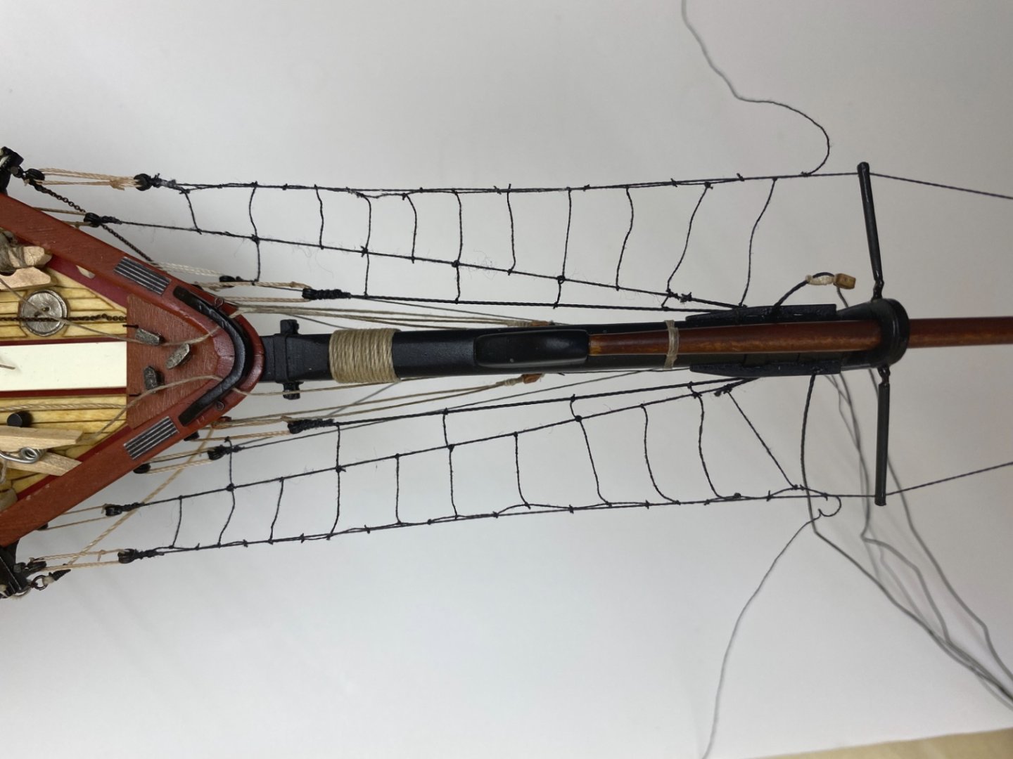
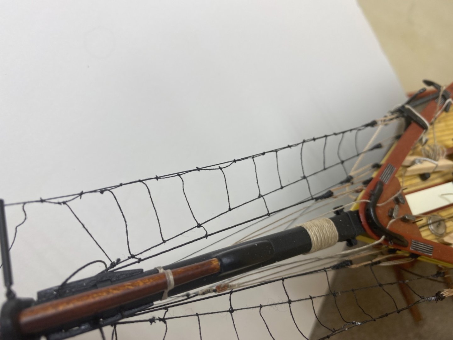
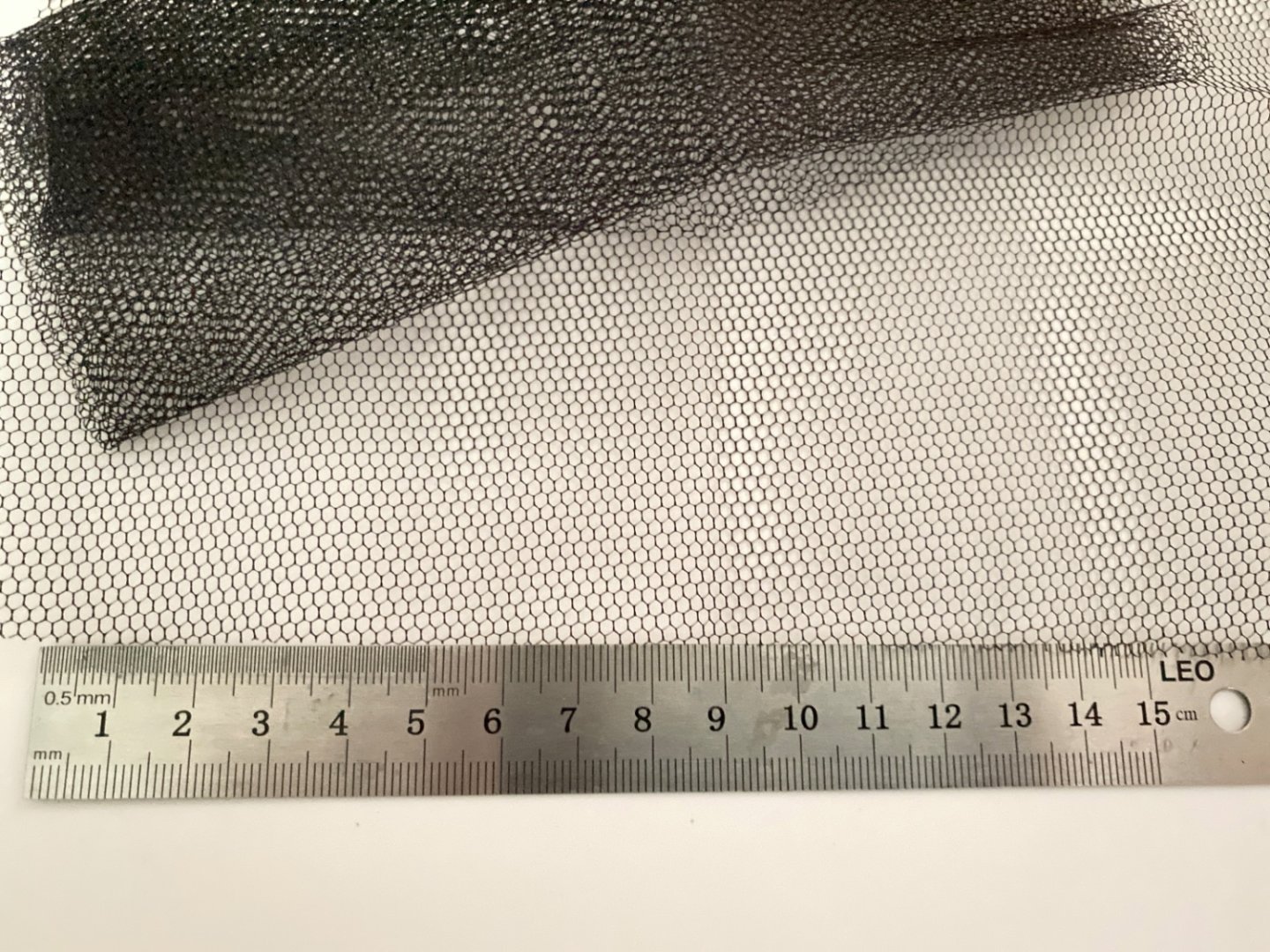
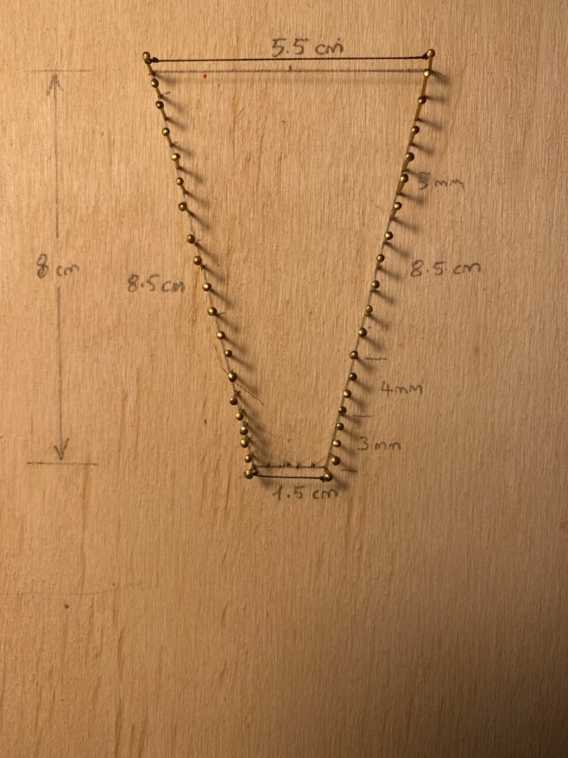
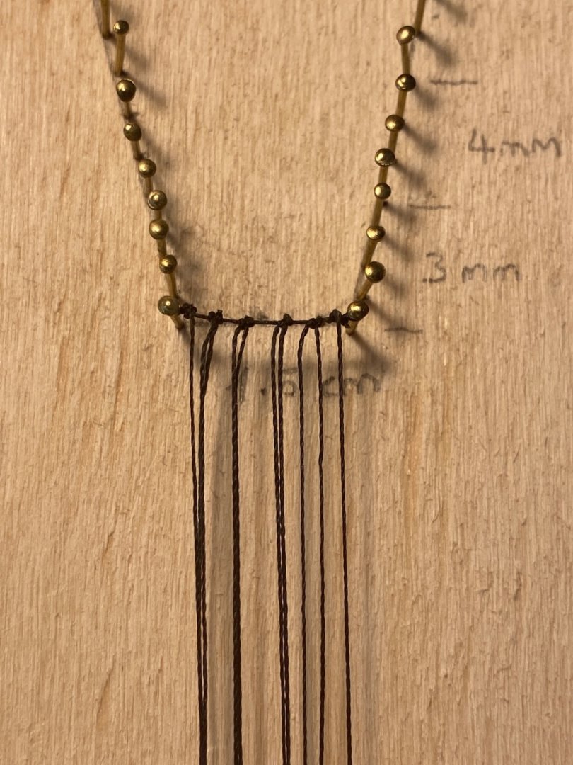
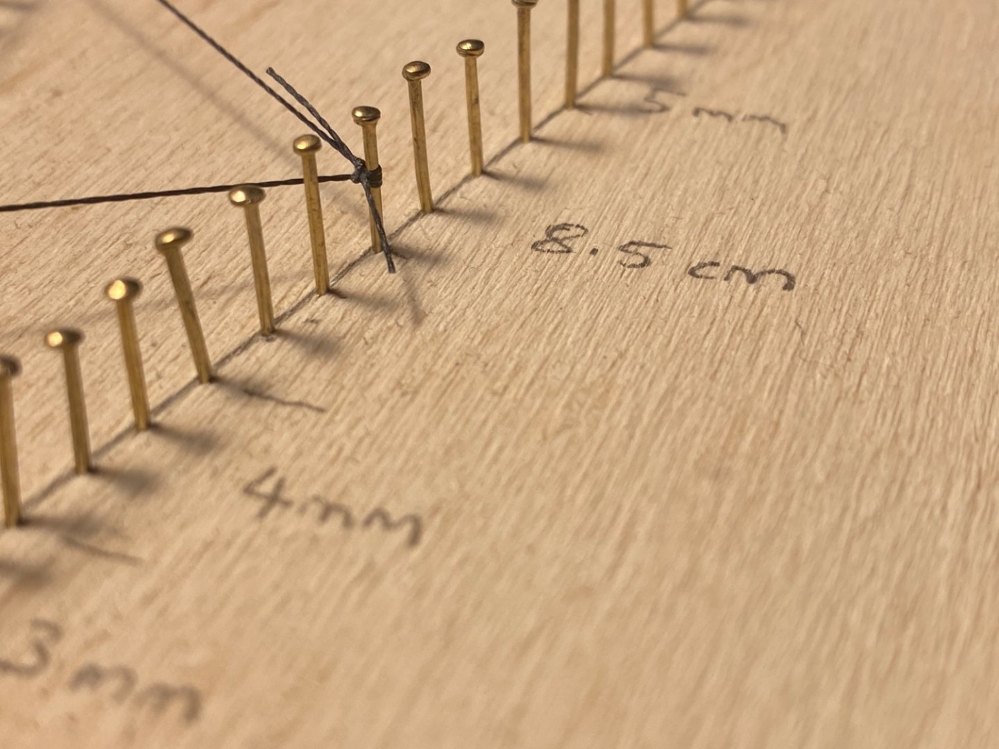
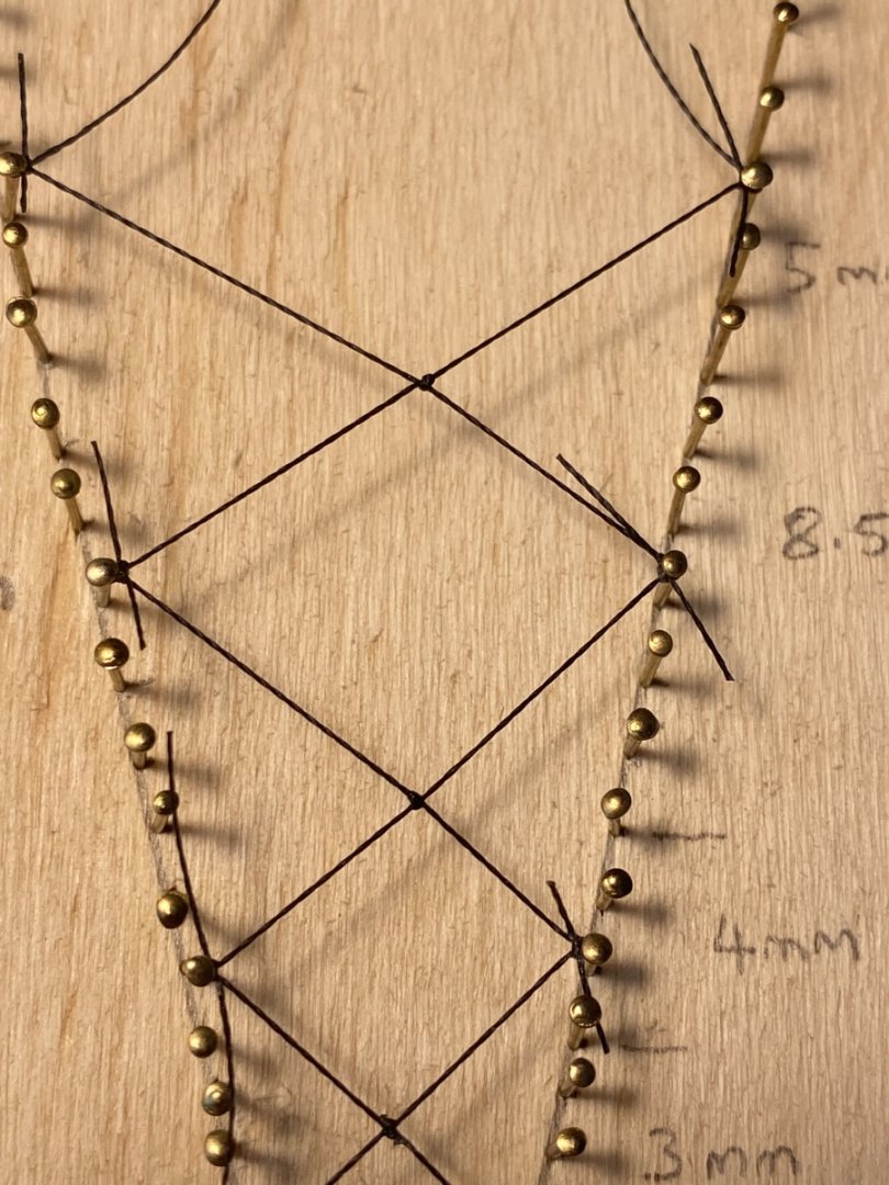
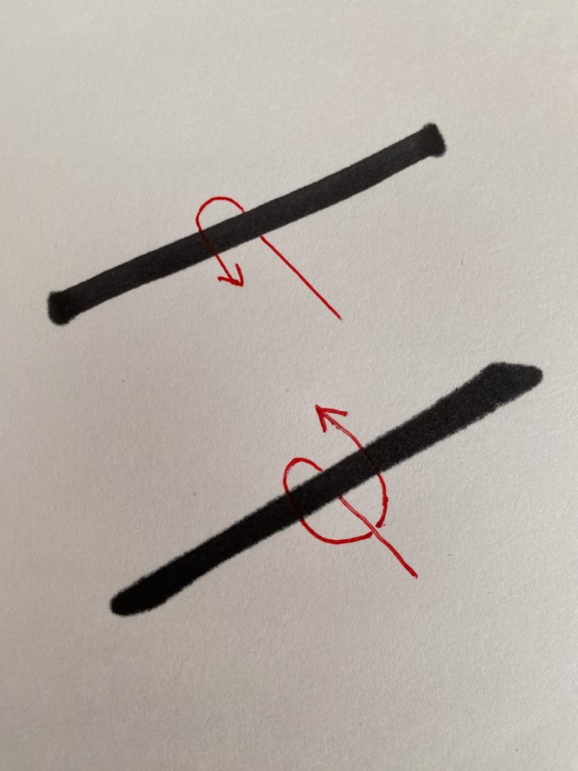
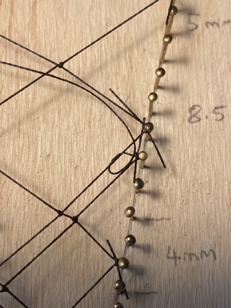
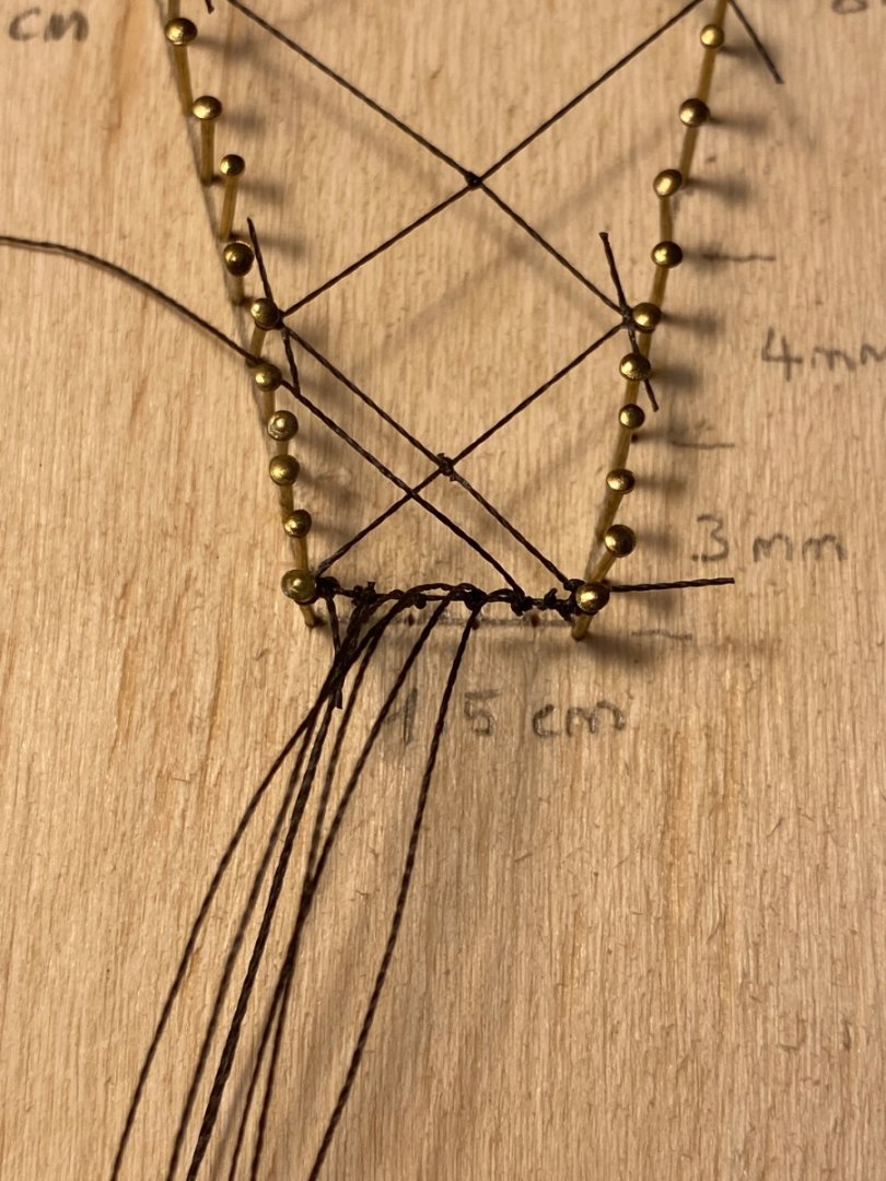
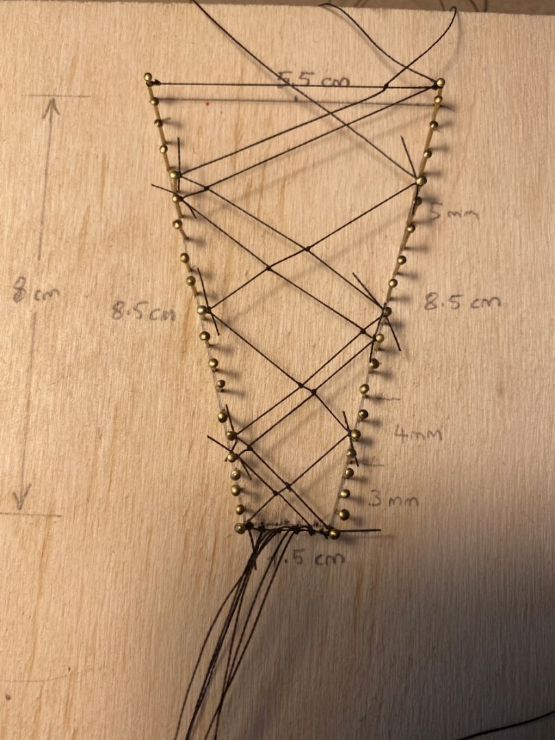
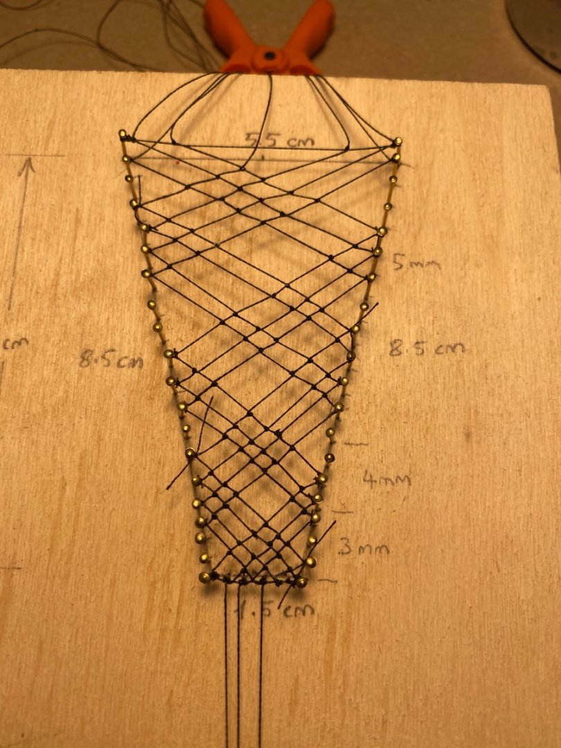
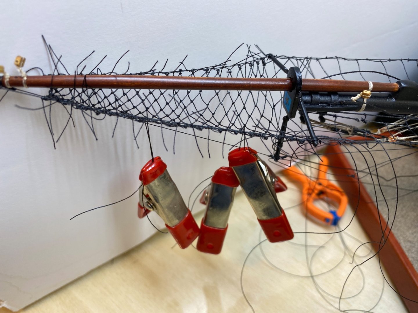
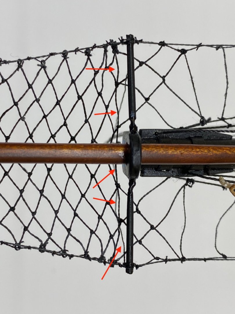
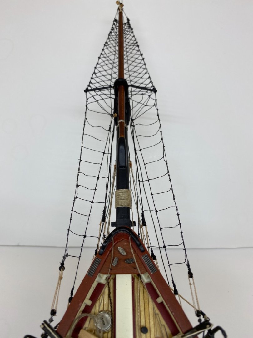
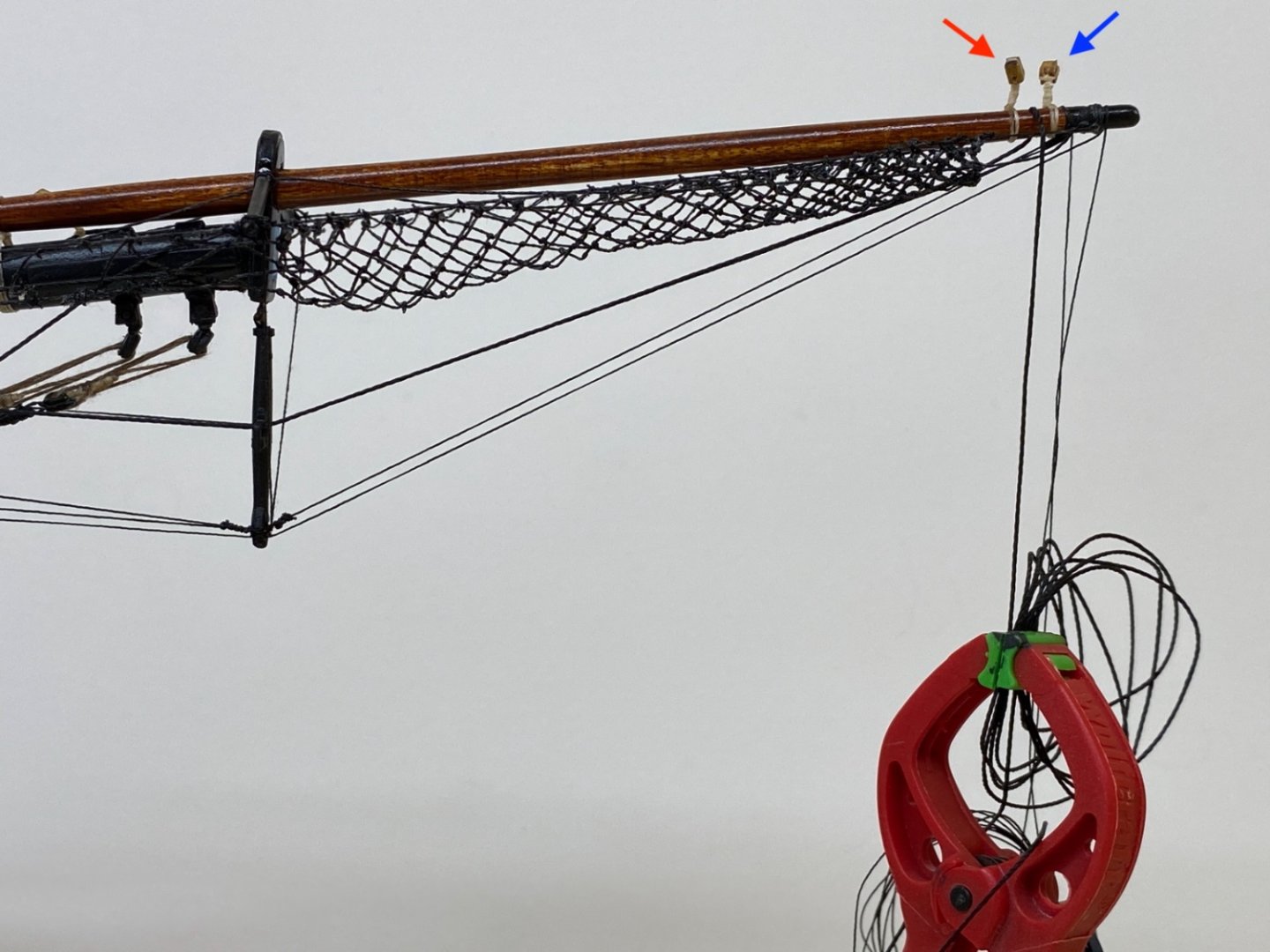
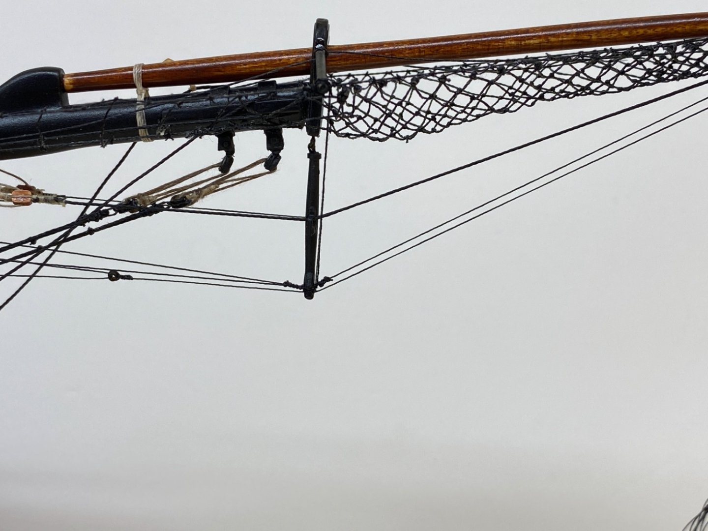
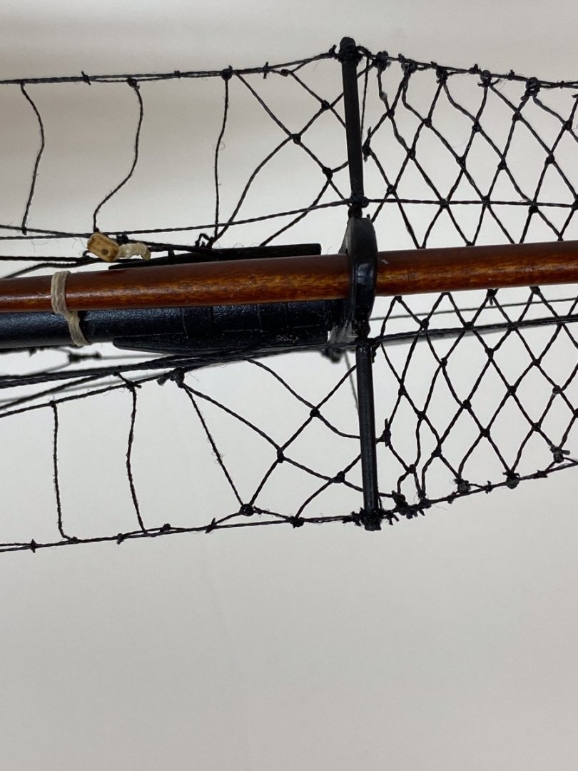
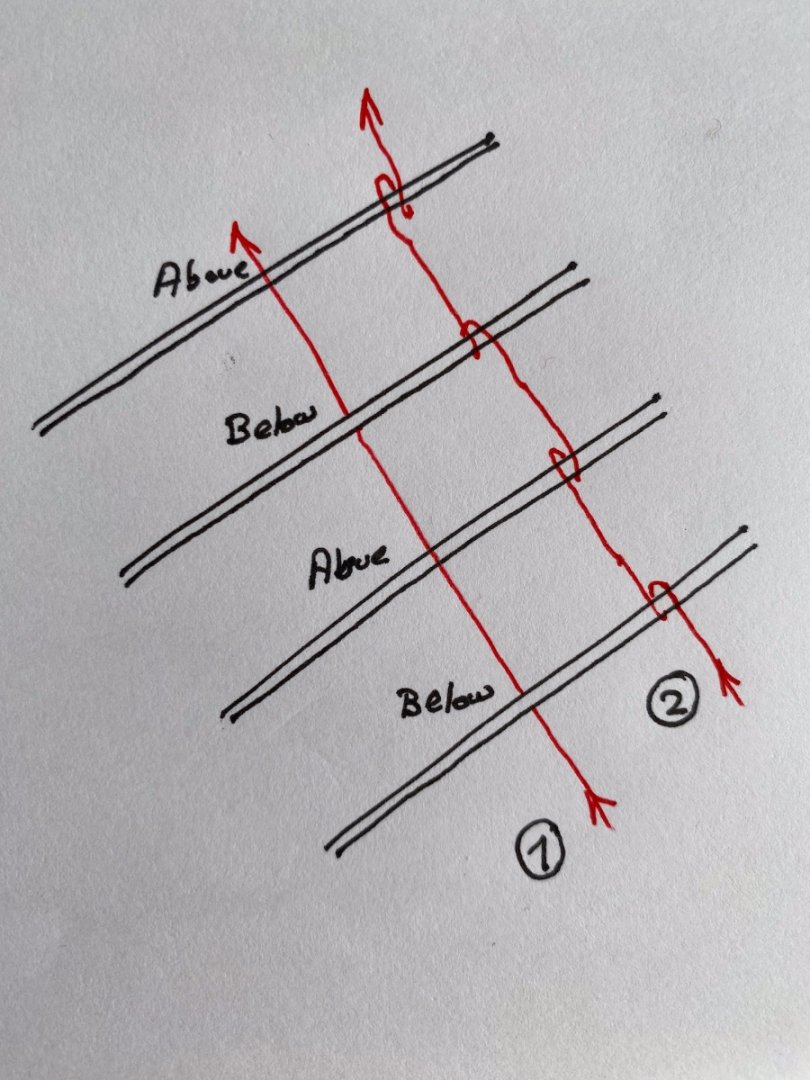
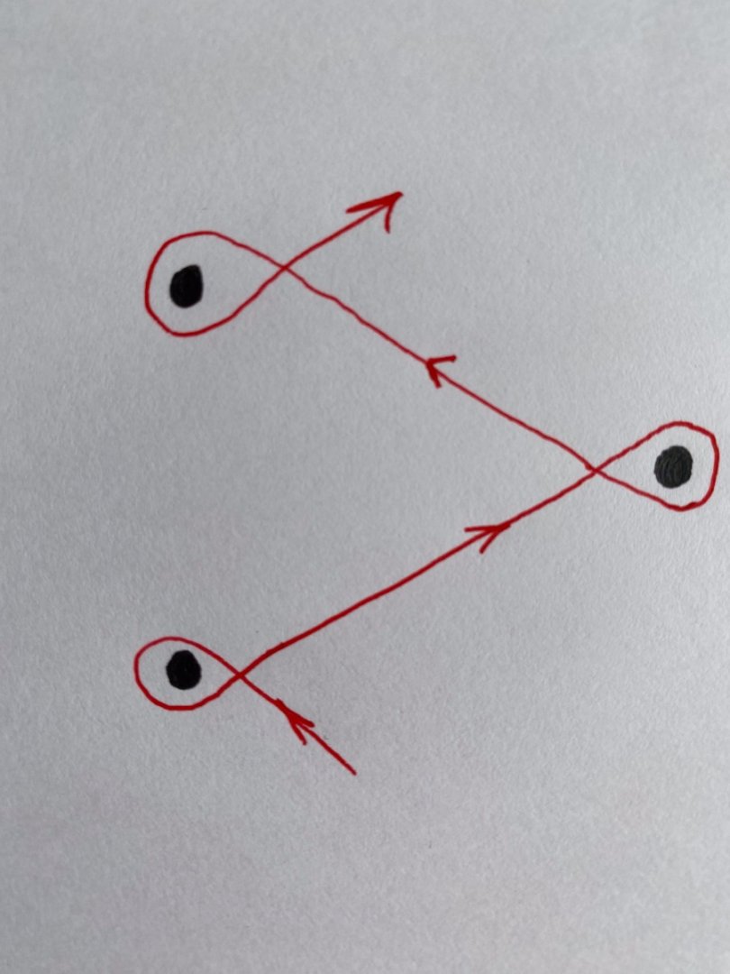
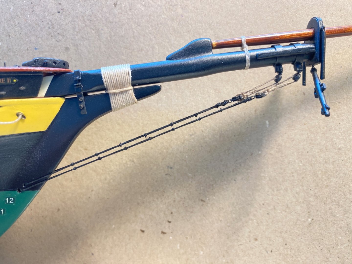
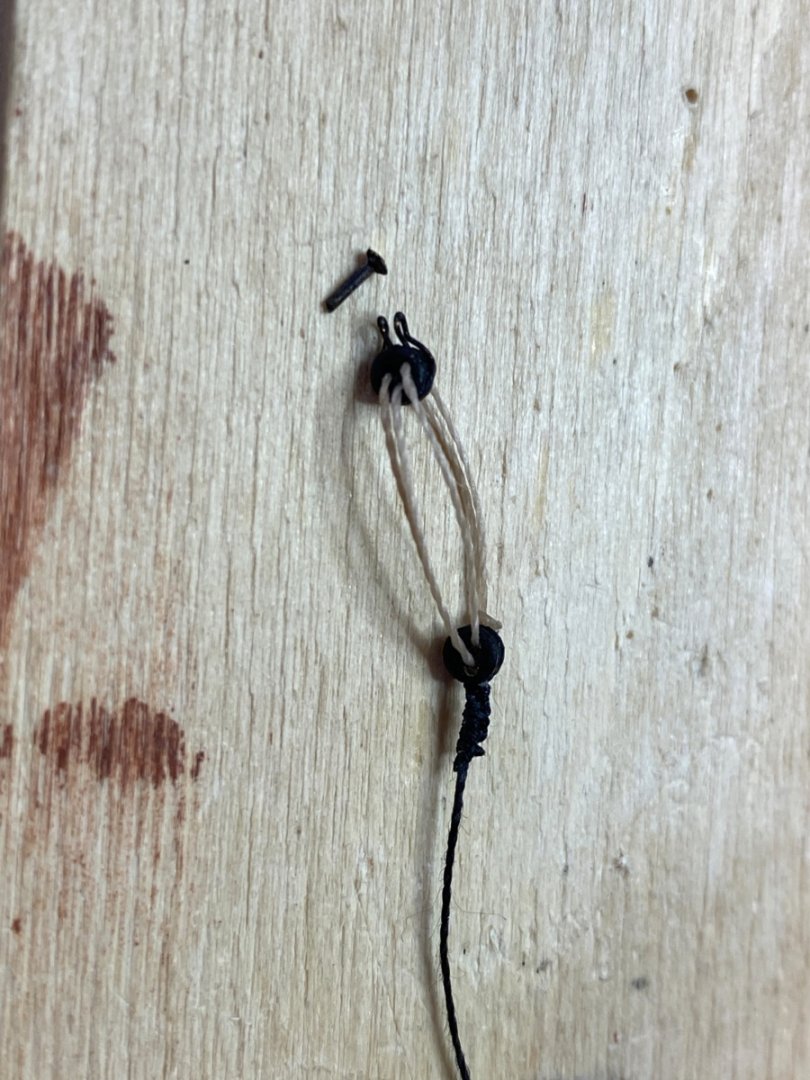
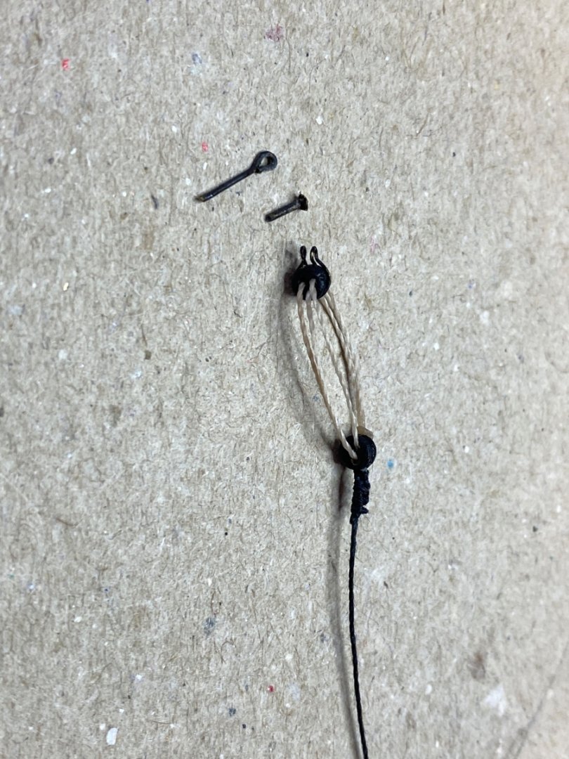
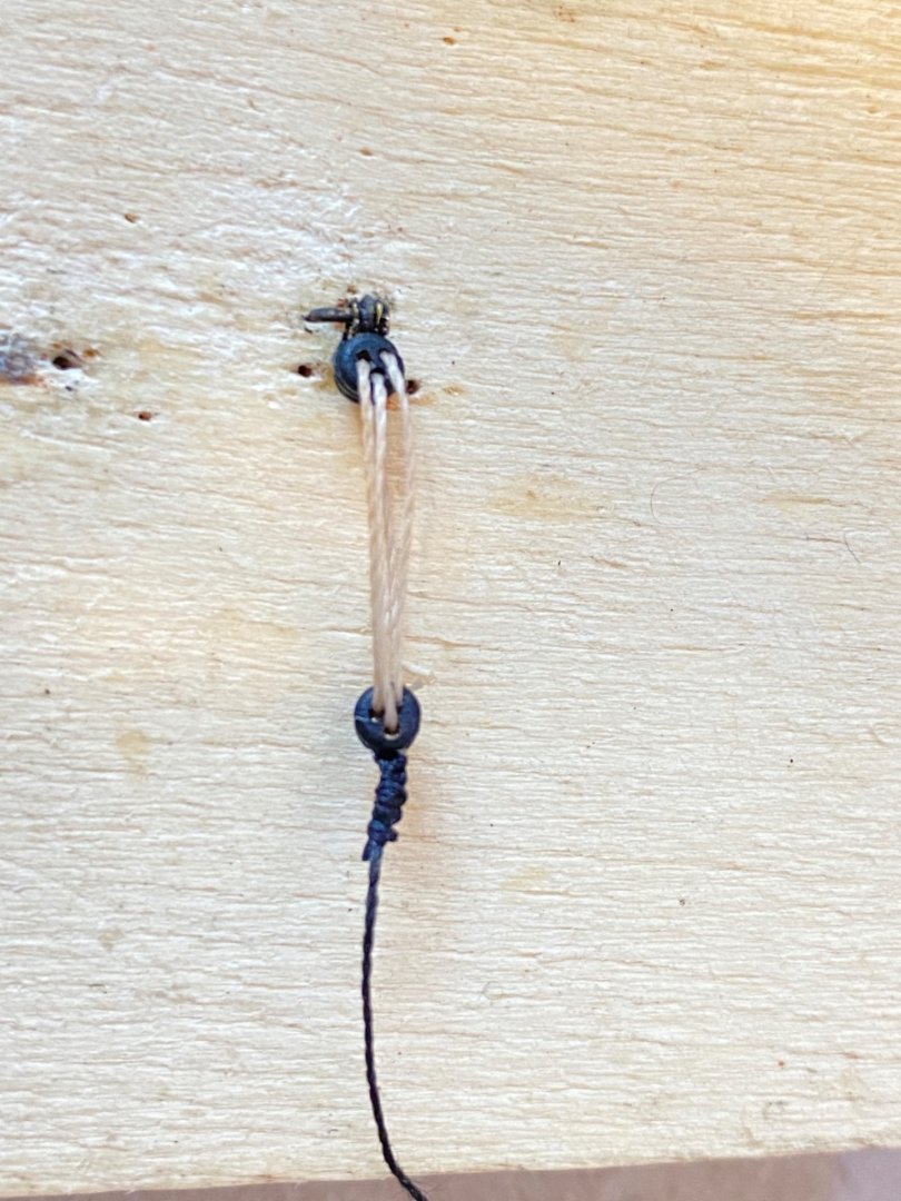
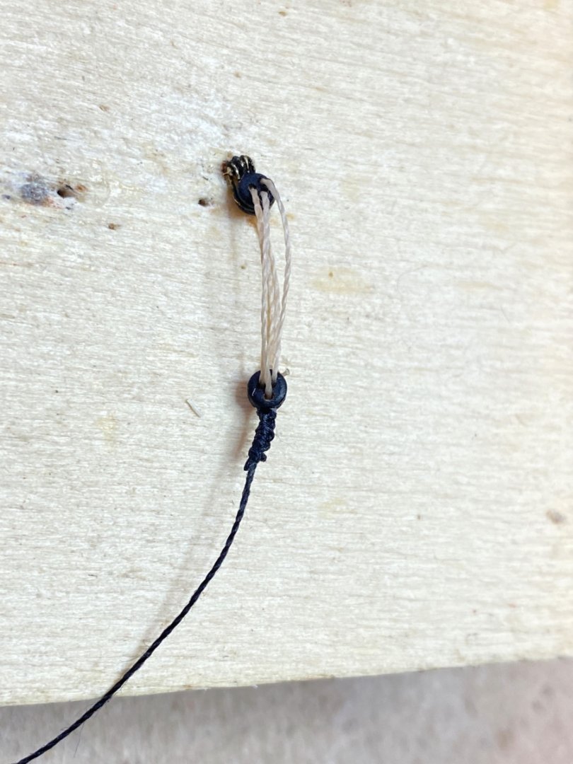
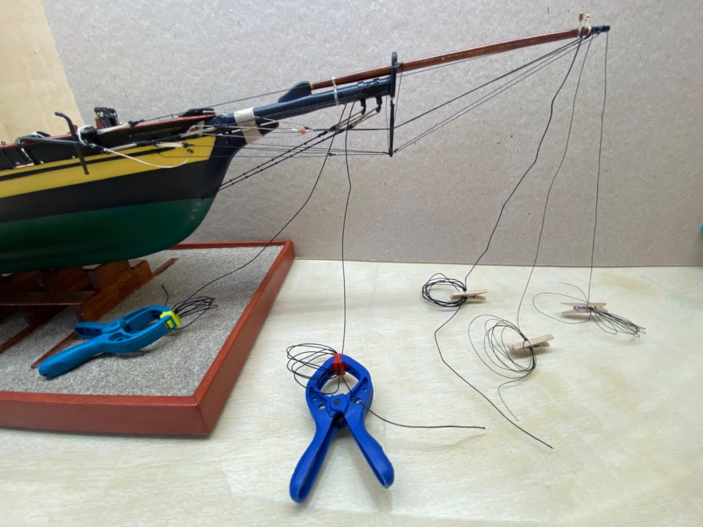
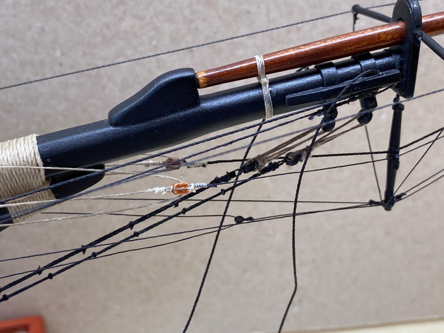
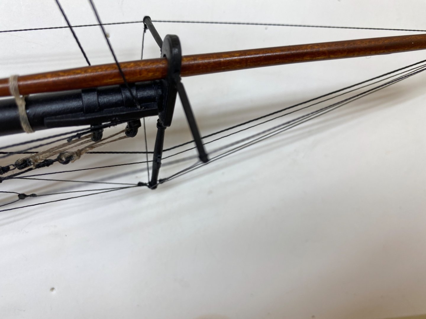
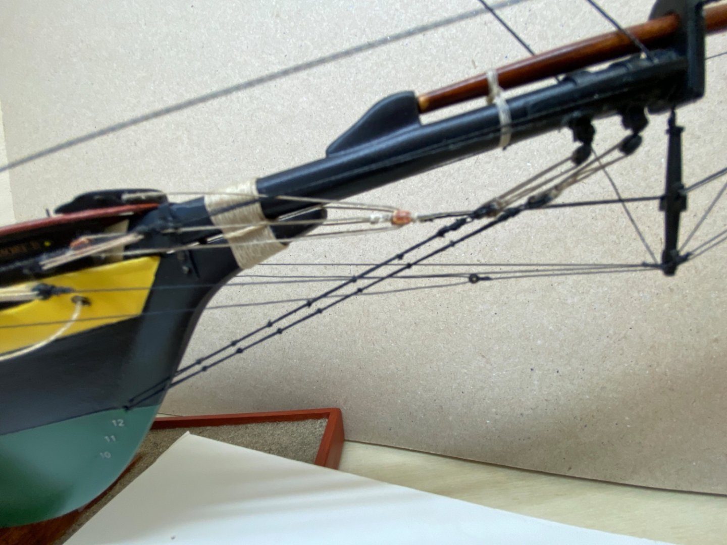
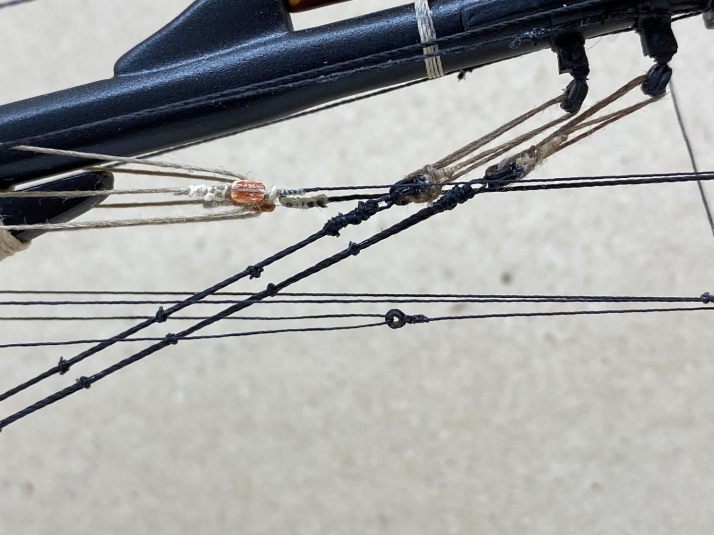
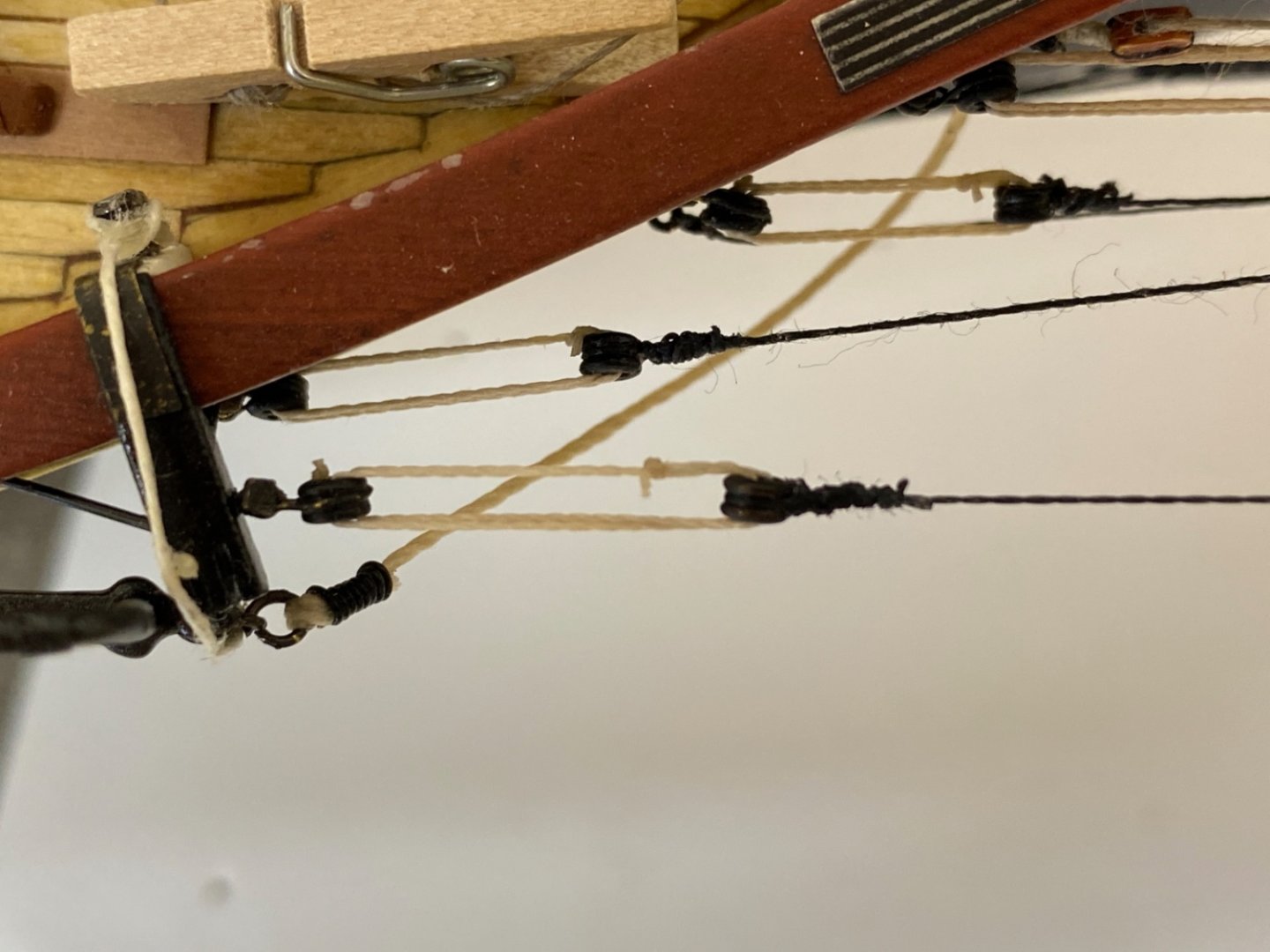
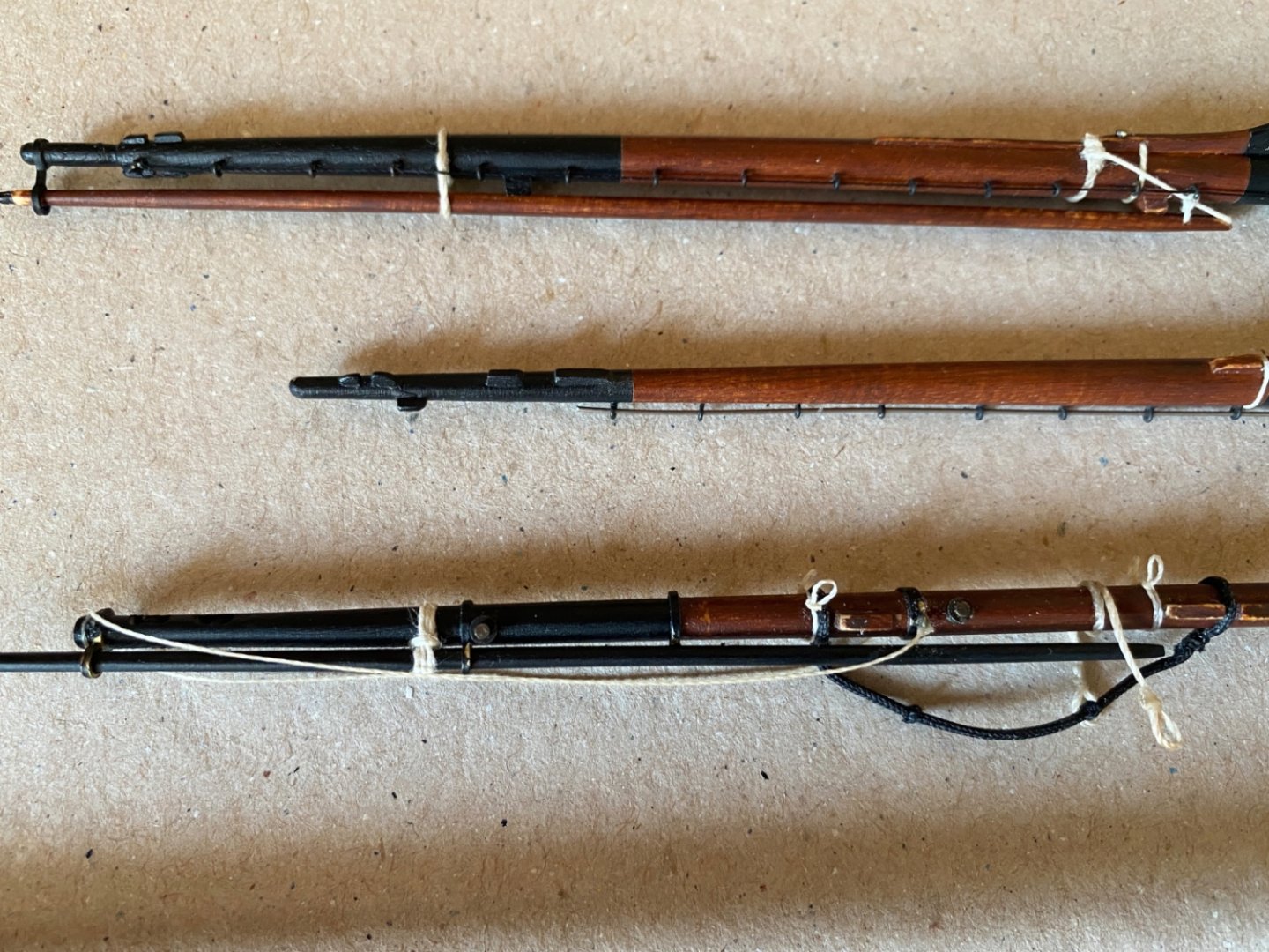
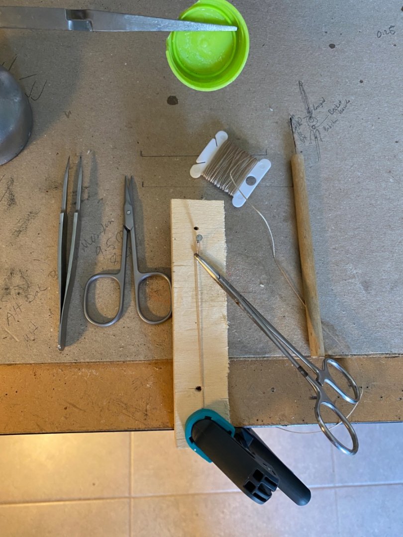
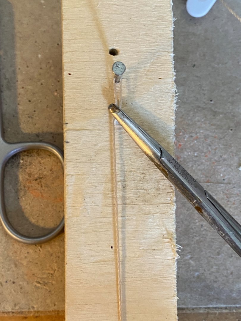
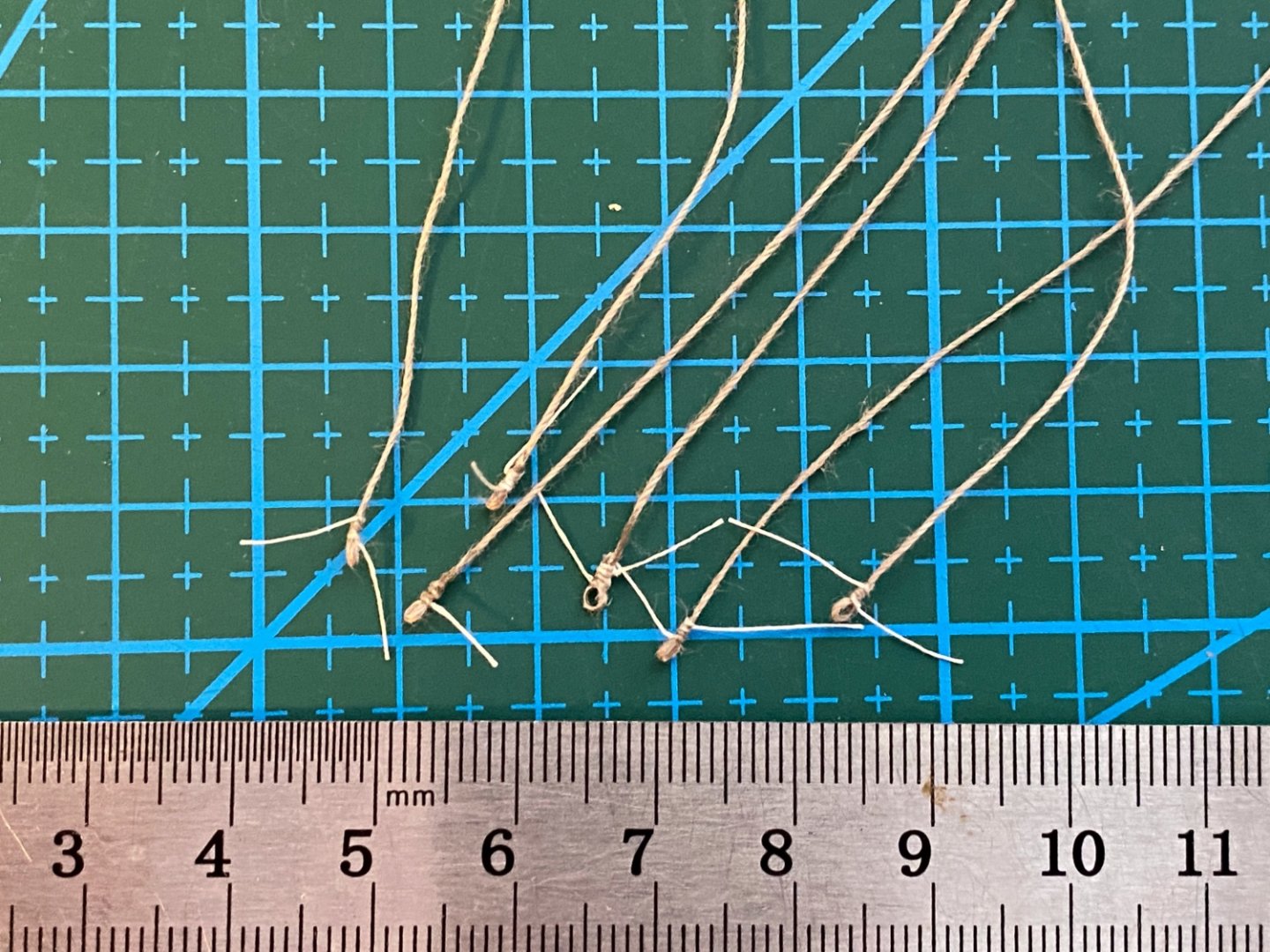
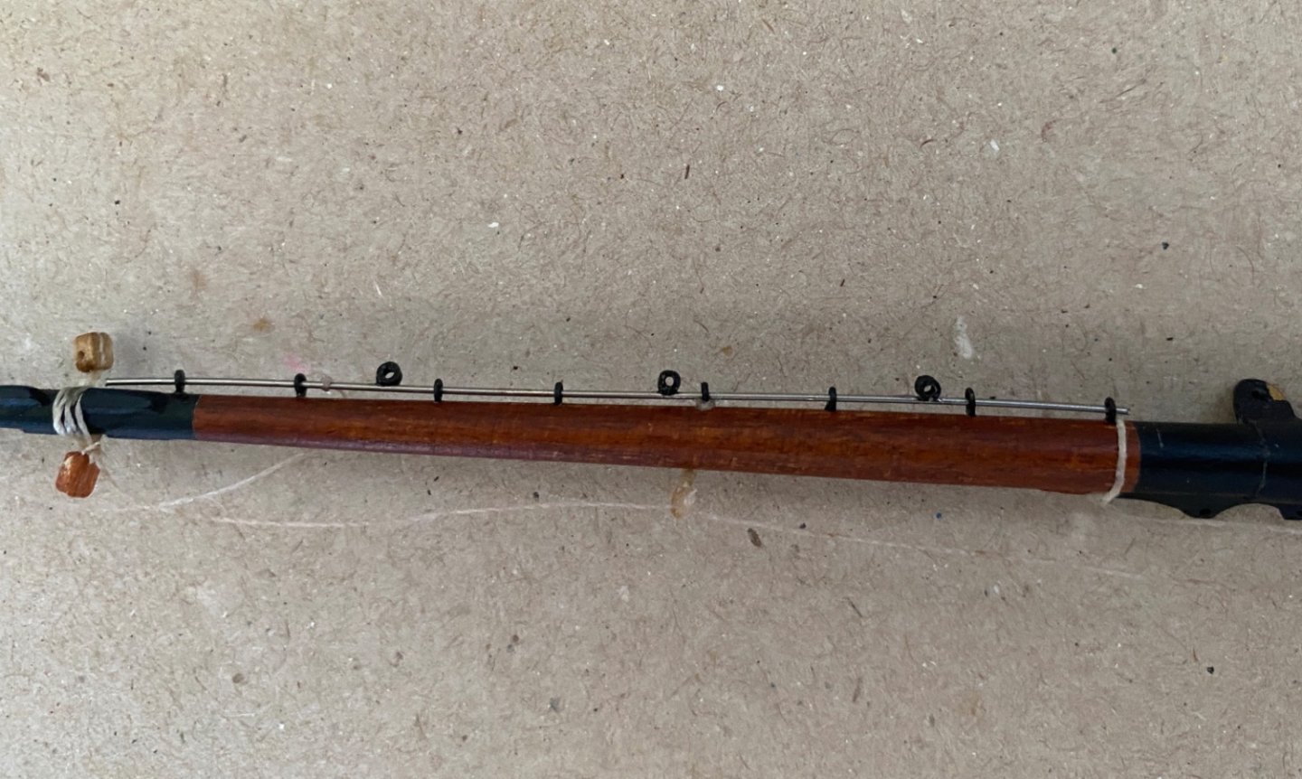
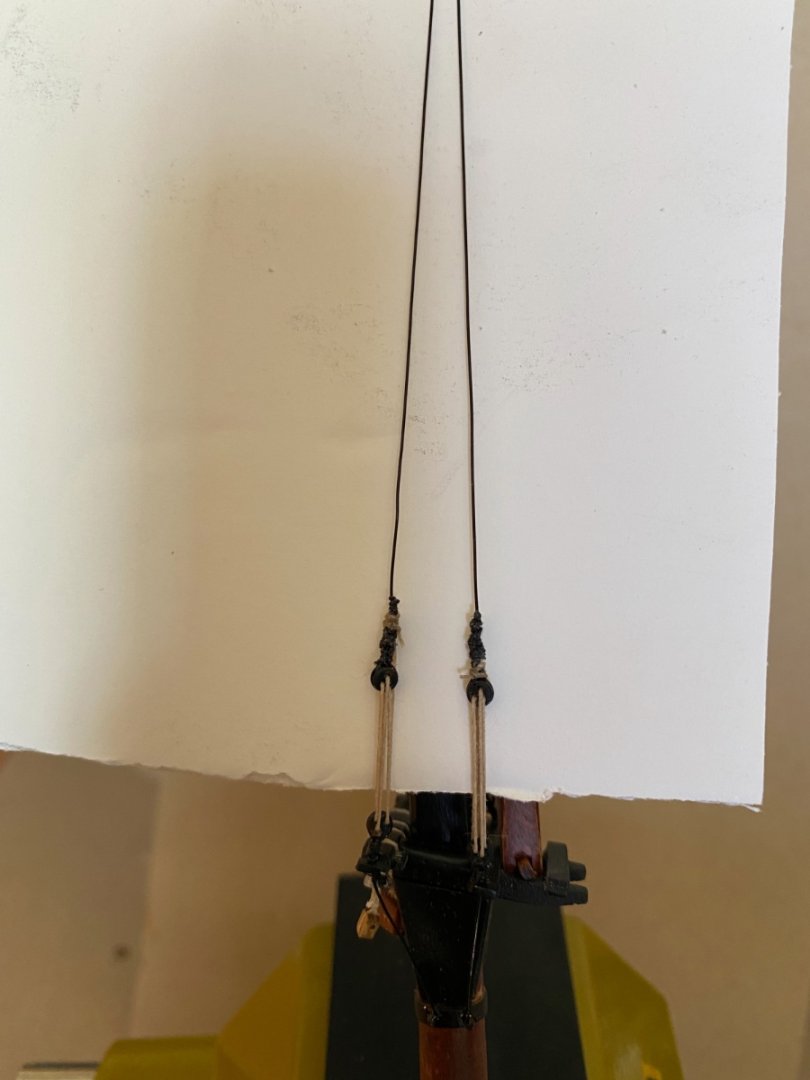
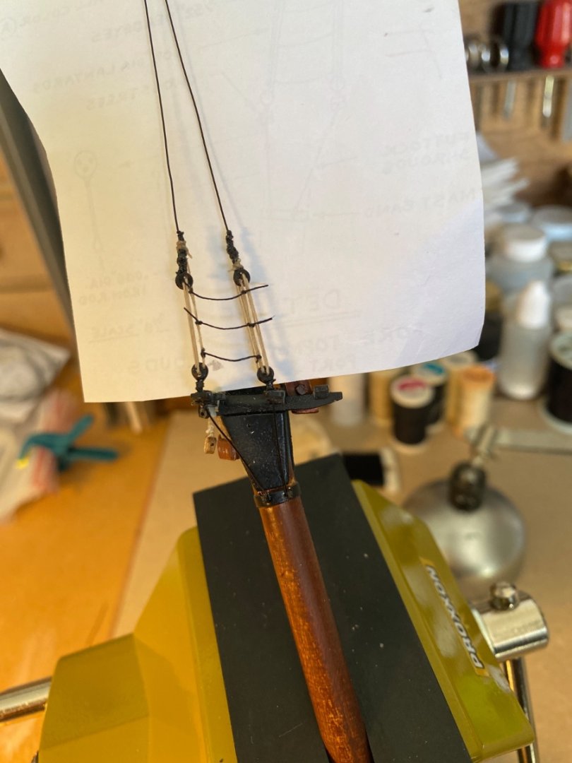
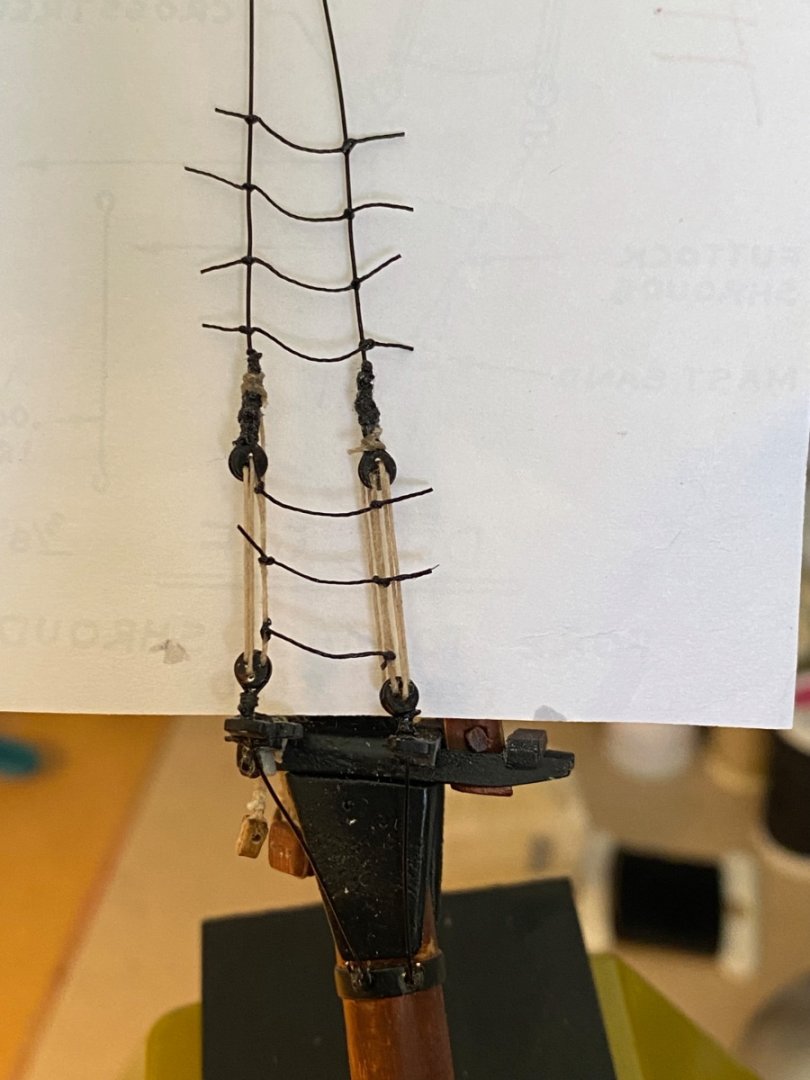
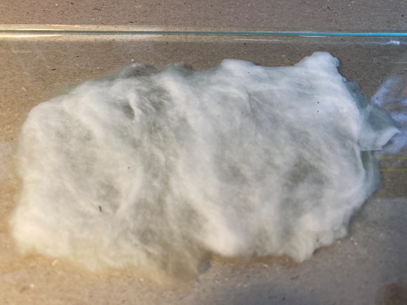
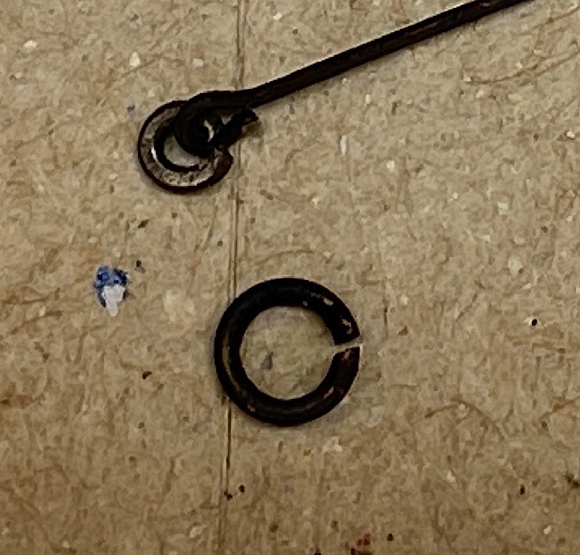
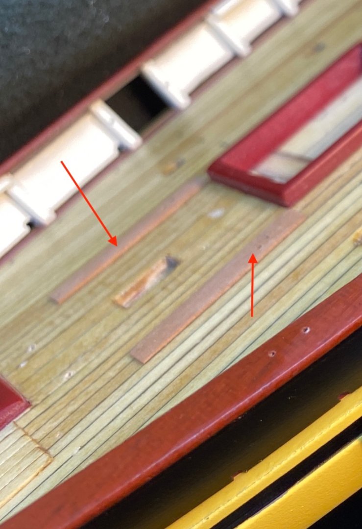
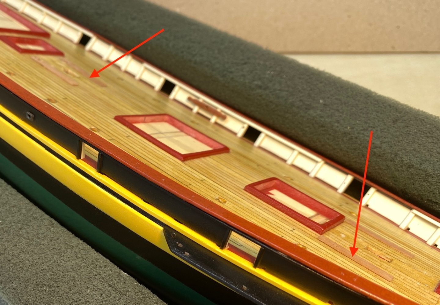
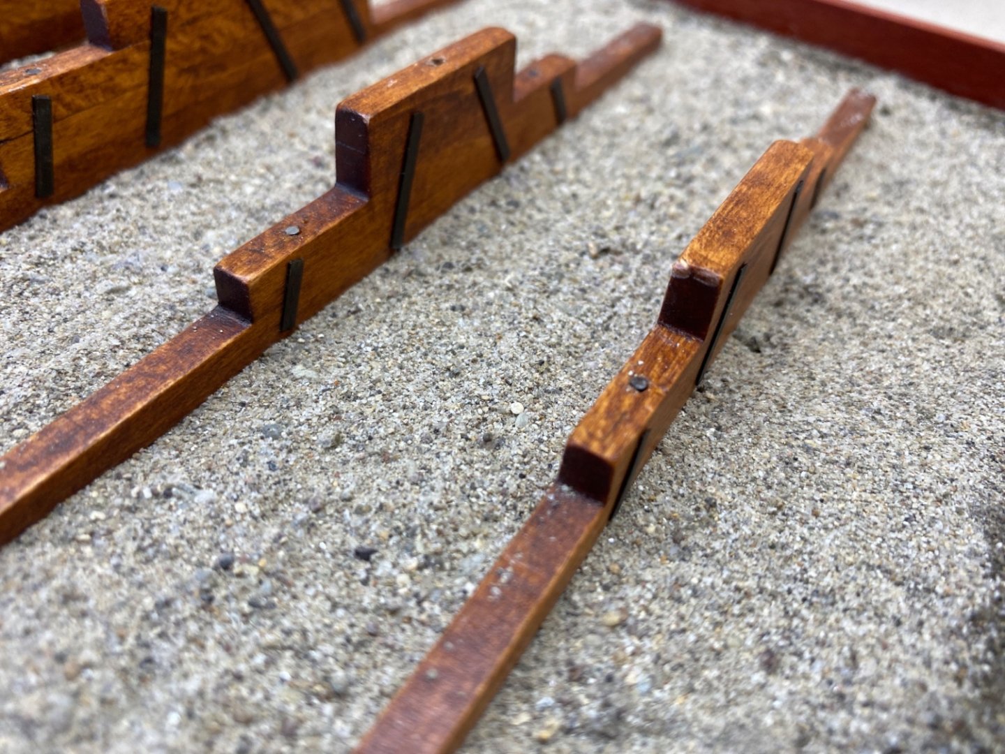
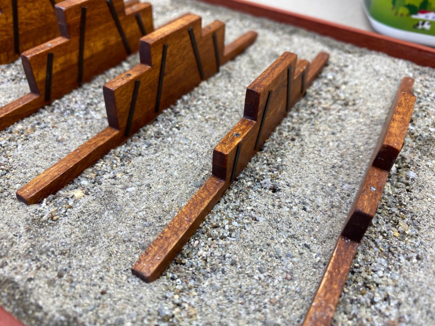
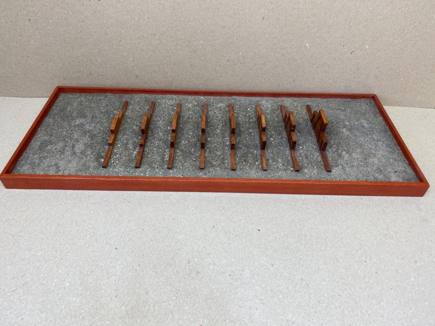
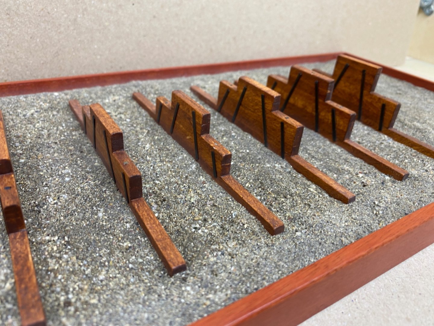
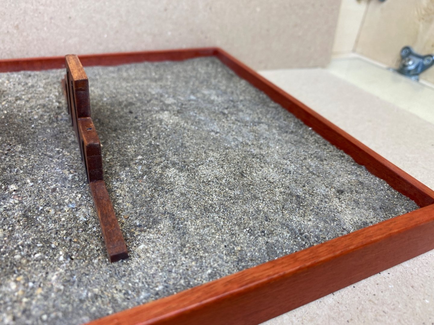
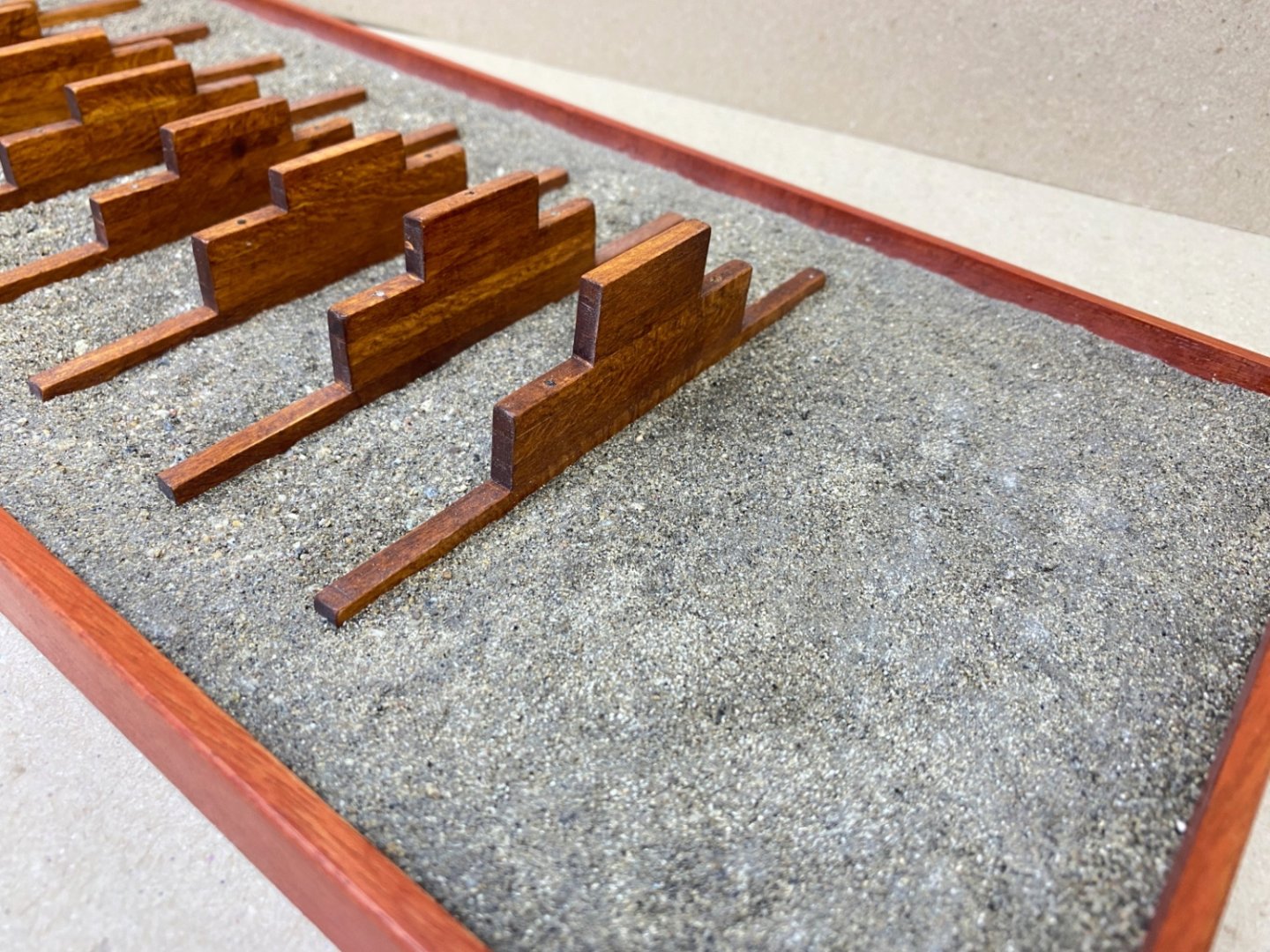
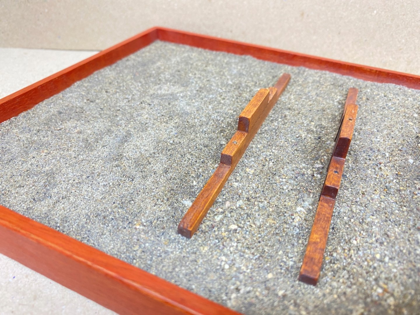
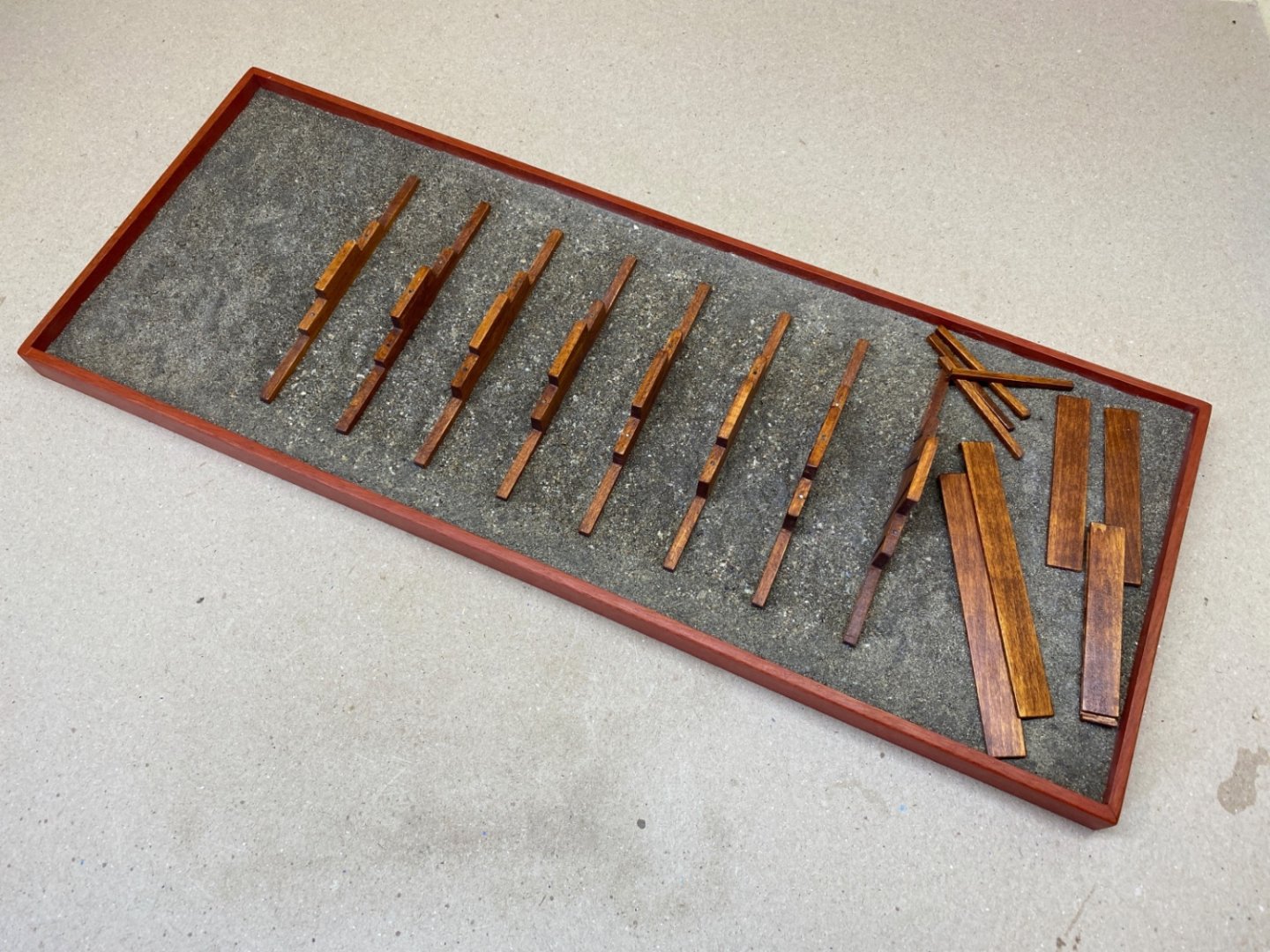
Other than the rigging lines described in the previous post, bowsprit has also have a safety netting between the Jib Boom spreaders and the Jib Boom tip, and a loose netting between the bow and Jib Boom spreaders, as seen in the photo below from the plan. Loose netting between the bow and jib boom spreaders have transverse lines between jib boom, bowsprit shrouds (guys) and fore stays both at port and starboard sides. However these line are not sized directly to jib boom guy but to another line which is intermittently seized to jib boom guy and goes all the way to the tip of jib boom. See the photo below. I started with this part of netting. Starboard side: seized lines between jib boom guy and bowsprit shrouds (guys). Here in this photo port side was also finished with the lines also between bowsprit shroud (guys) and fore stays which are less in number. Red arrows indicate the lines seized to jib boom guy which were left long purposefully in order to reach jib boom tip. Also note the single block seized to port fore stay through which Forestay sail downhaul line will be reeved in the later stages. The safety netting between jib boom spreaders and jib boom tip is way more complex and hard to build when compared to the netting described above. In almost all the models finished , this step was ignored and skipped. Modeler Jdbondy did an excellent job and build a netting that was almost exactly the same as the real ship's netting. Modeler Karleop probably used Artesania Latina product coded ART87846 in his model which was the solution for me initially. Here is the photo of that product. It is not hard to see that all holes of the netting are the same size and it will surely be out of scale when used in the model, because the size of the holes on the ship's netting get larger towards the bow. So I decided to build my own netting. After a lot of trial errors here is how I did it. After taking measurements from the model and paying attention to the downwards slope of the netting, a jig was build as you see in the photo below. On the sides of the figure nails were placed with 3, 4 and 5 mm apart, increasing towards aft of the netting.At the tip and the base of the figure 0.2 mm black thread was tied horizontally. The 1.5 cm end will be jib boom tip side of the netting. 5.5 cm side will be the base of the netting at jib boom spreaders. 10 strands of 0.2 mm black thread were seized to the 1.5 cm line. 2 at the corners and 2 strands each at 4 points placed with equal distance from the two lateral ones. I started to weave the strands with the right corner one.The line was looped around the 5th nail on the opposite side twice leaving 4 pins to 4 strands , one from each of the middle 4 pairs. Then the line looped twice around the 5th pin on the opposite side and so on. An overhead knot was tied at each looped area. A touch of liquid CA glue was applied later. The second thread is the left corner one. This line was weaved just like the first one. However this line crossed the previous one at some points. I did not use knots here but looped the line around the one to be crossed. Here is how I did it. I passed the line under the previously laid one, lopped around and came back, looped under itself and passed this time above the previous laid one. A touch of CA glue was applied at these points also. Maybe and I hope the diagram below explains it. I continued the weaving with the right out pair line . Left out pair line Then right and left in pair lines followed, leaving 4 lines in middle left. And the weaving continued in right out, left out , right in and left in sequence completing the process. At the end of the weaving job. The end of the lines above were knotted to the horizontal line and left uncut. The uncut ends will later be connected to the loose holed netting which was already done. Here is the netting after the nails were removed. Remember the line which was seized to jib boom guy at the beginning of this post ? That line will reeve through the holes at the sides of the build netting. The build net was first adapted to its place. The line I mentioned above reeved through the holes and it was seized to jib boom guy by simple overhead knots between each hole it passed. Here are some photos. Small weights were hanged in order to create a downward slope after liquid CA was applied to the target netting area. The excess ropes of the knots were cut. Note that uncut lines were connected with the loose holed netting. Also note and remember the horizontal line at the base (red arrows) They are cut near the knots leaving a more realistic space. (Red arrows) The safety netting was finished and installed. Footropes from bow fairlead eyebolts (p/s) to first jib boom spreaders and then to jib boom tip were seized (Red arrows). Starboard side view. Arrows indicate single blocks for downhaul lines of jib sail (red) and jib topsail (blue). Closeup photo of the jib boom spreaders area. At that time I was very proud of myself and happy with the result. However now I can easily say that safety netting would have been much more better and realistic if I had kept some steps simpler. At the cross points of the lines there was no need to loop the line twice. One can easily weave the line without looping (1) or looping just once (2) like in the diagram photo below. The other step that could have been simplified was the looping of the line around the nail heads. As you can easily see in the photo, the holes formed by looping the line twice around the nail head were not uniform and even looking pleasant. Starting the loop at the far side of the nail head and doing it once and a simple overhead knot (Preferably with the smallest size thread) completed with a touch of CA glue would have been much better.


- 114 replies
-
- 4
-

-

-
- Pride of Baltimore II
- Model Shipways
- (and 1 more)
-
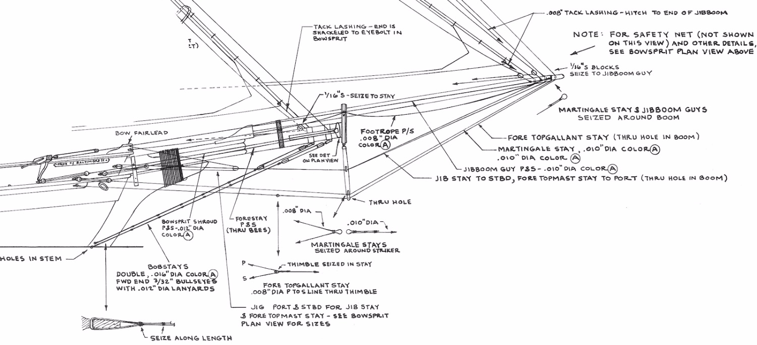
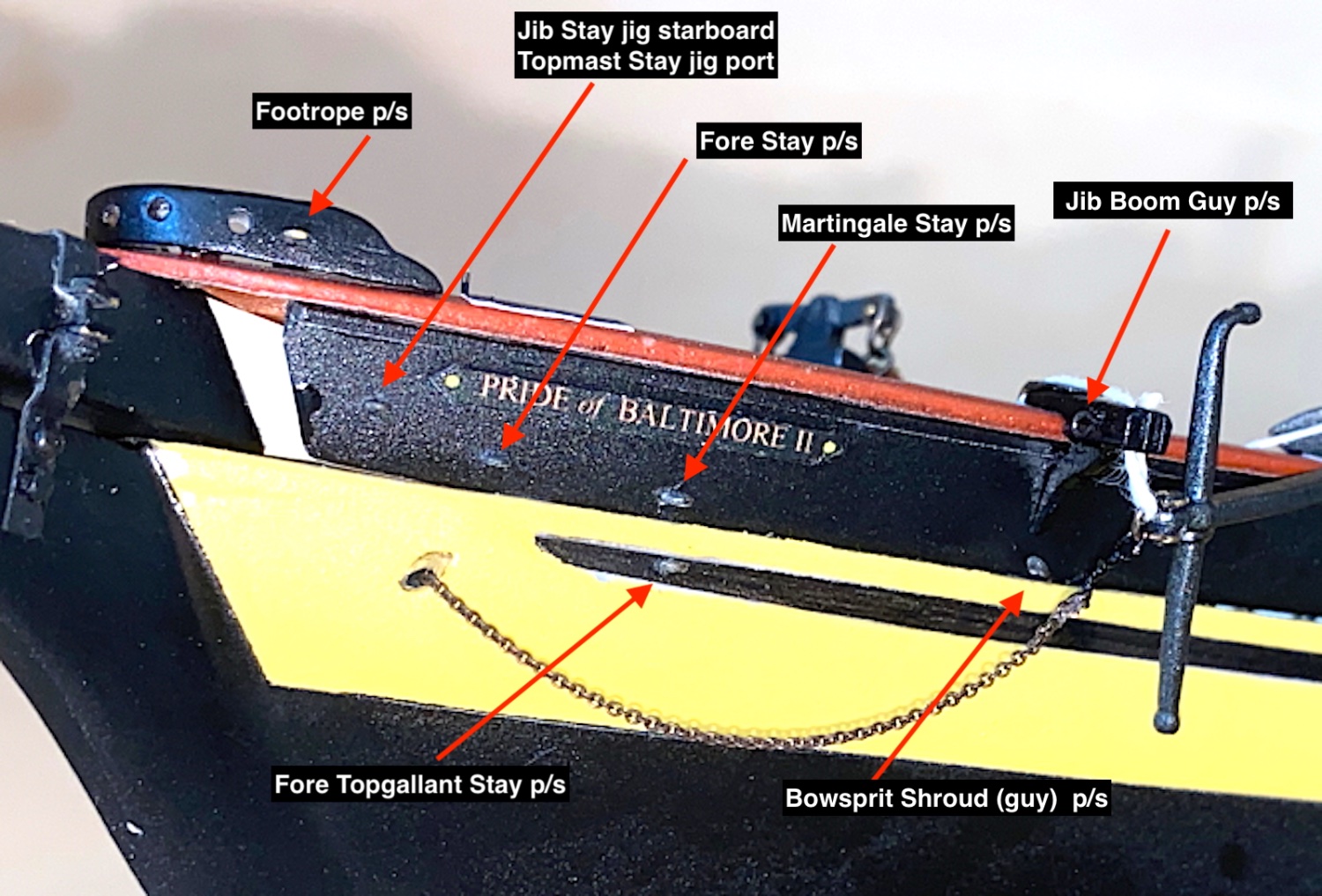
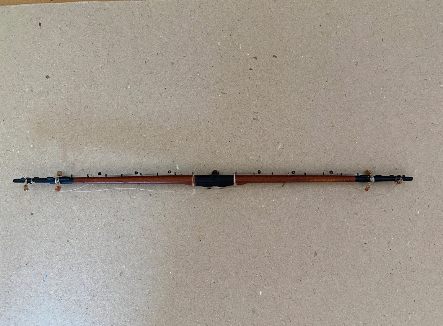
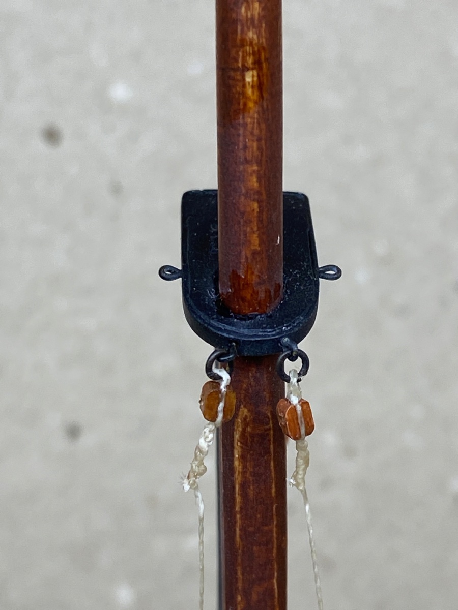
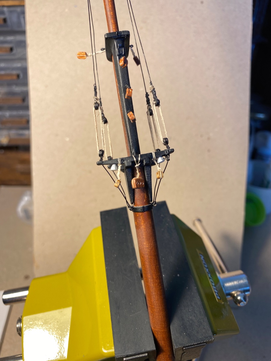
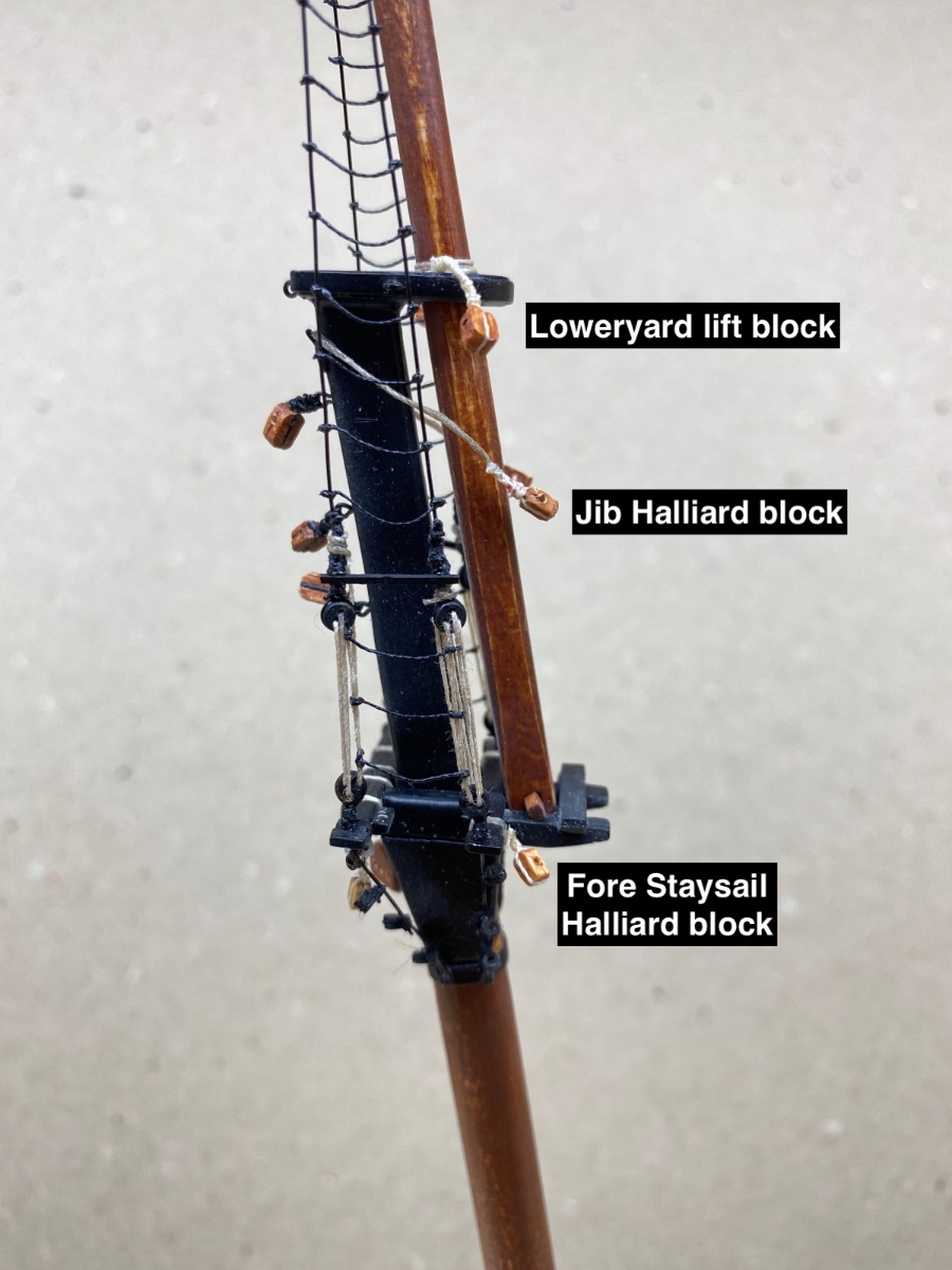
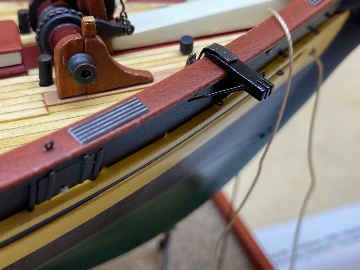
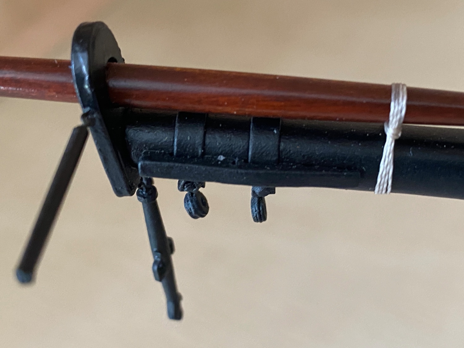
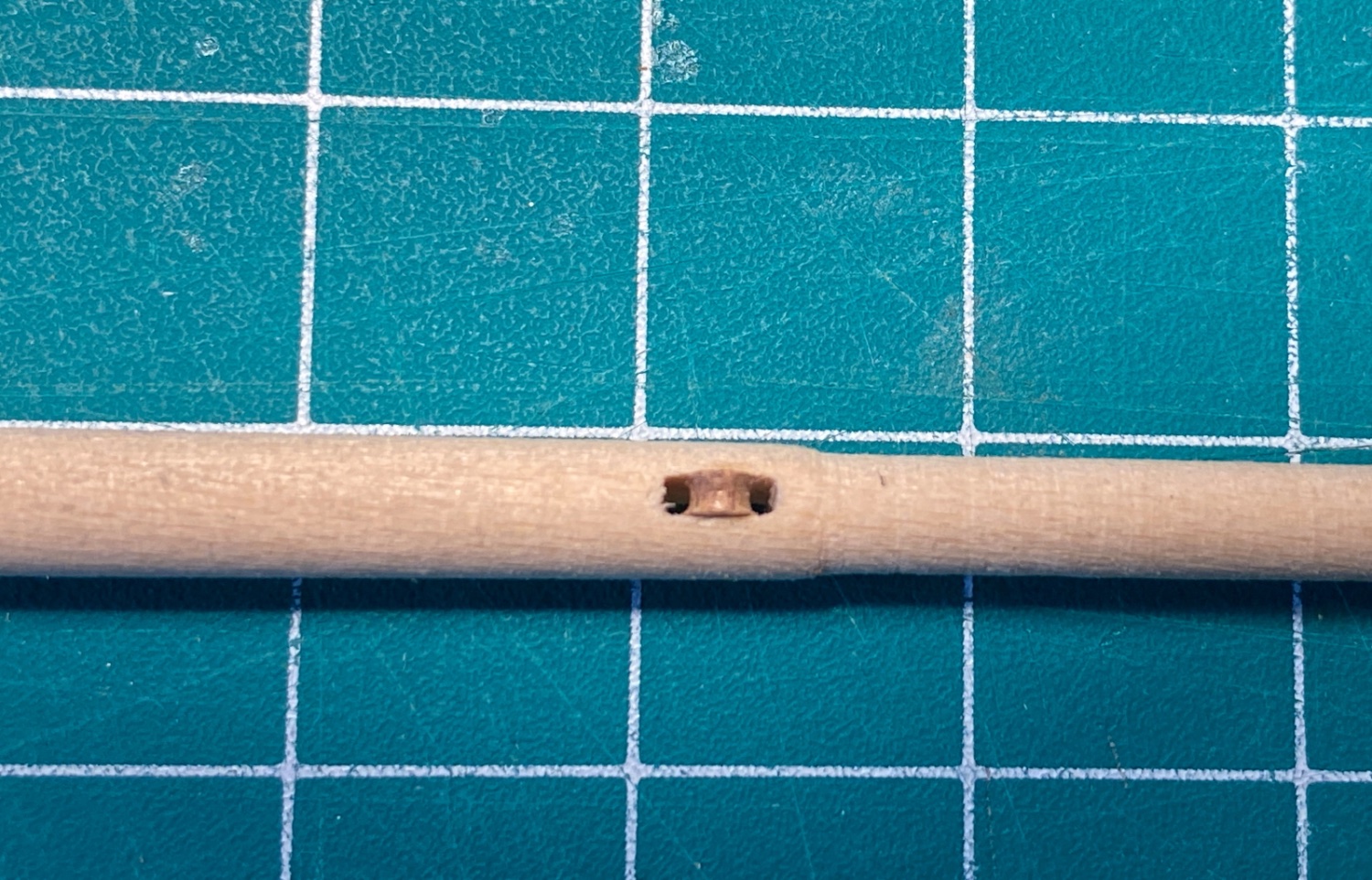
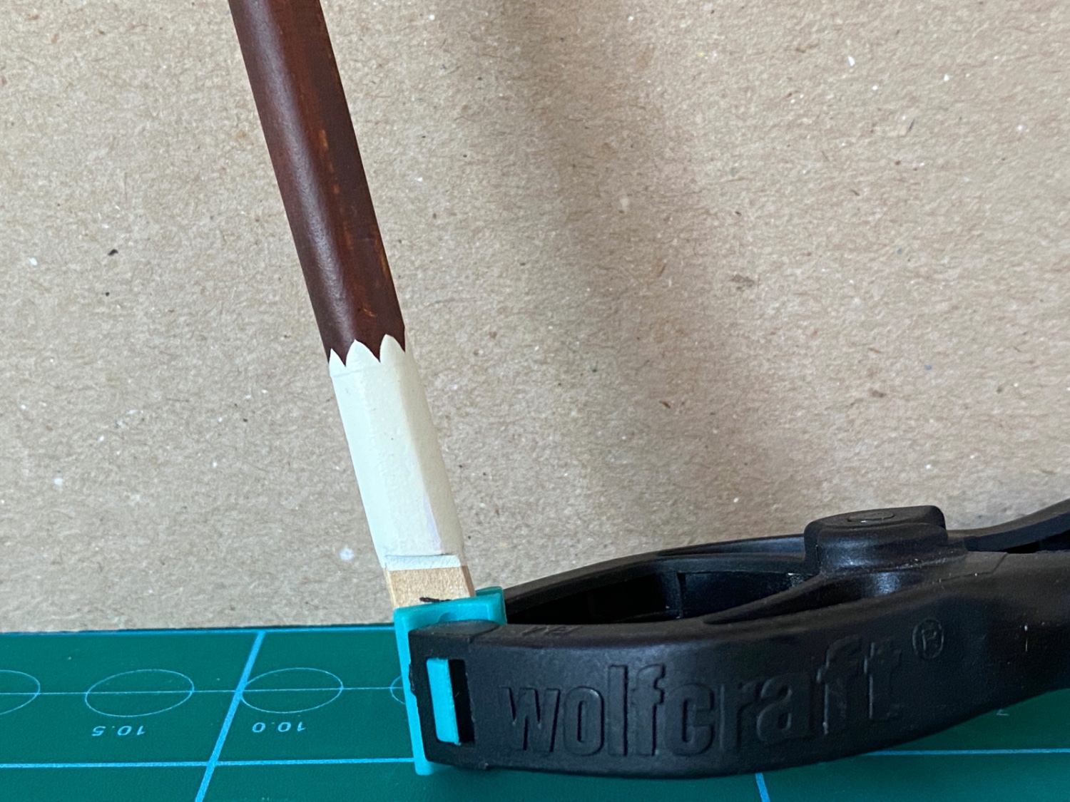
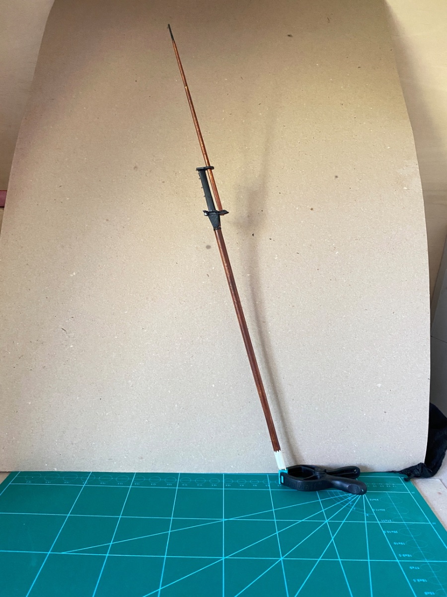
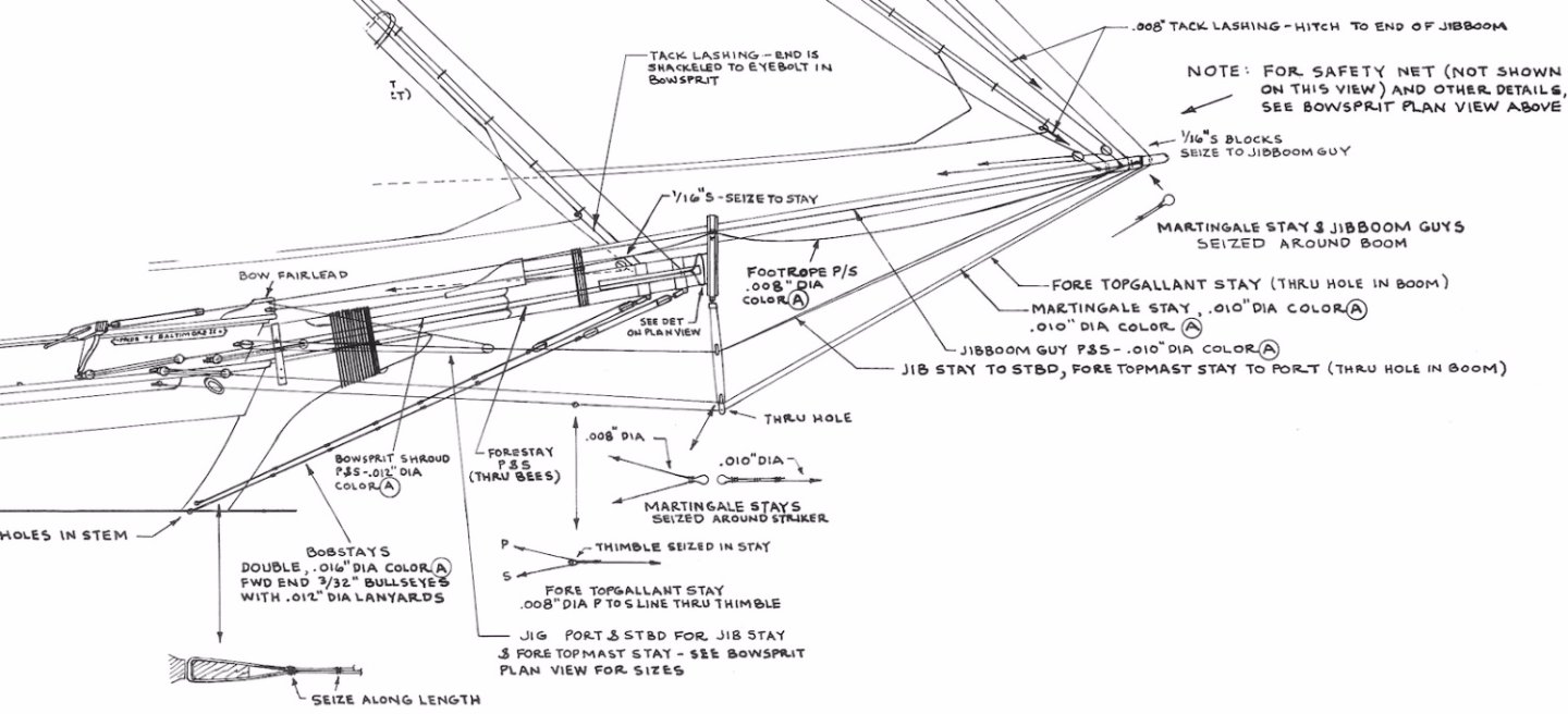
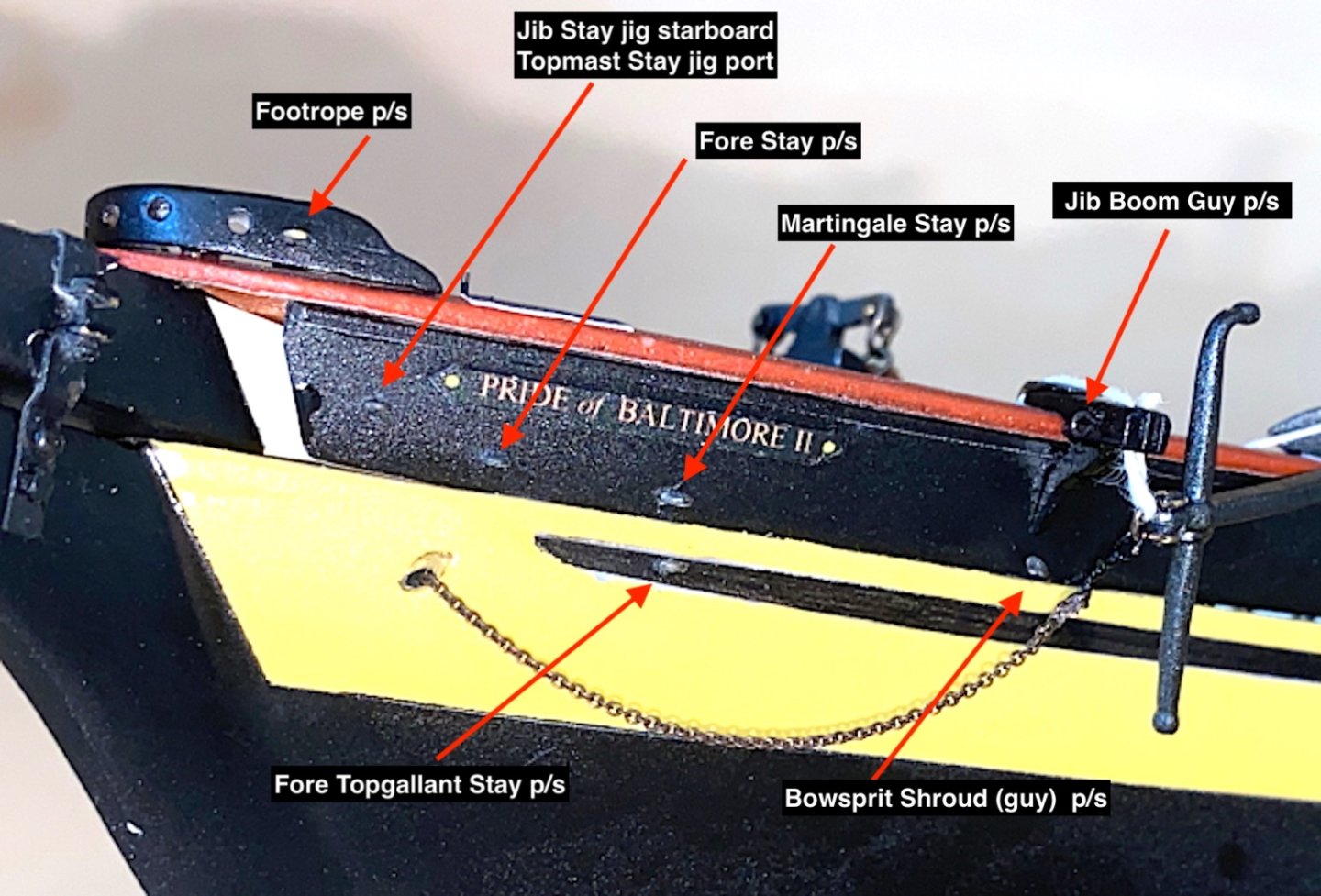
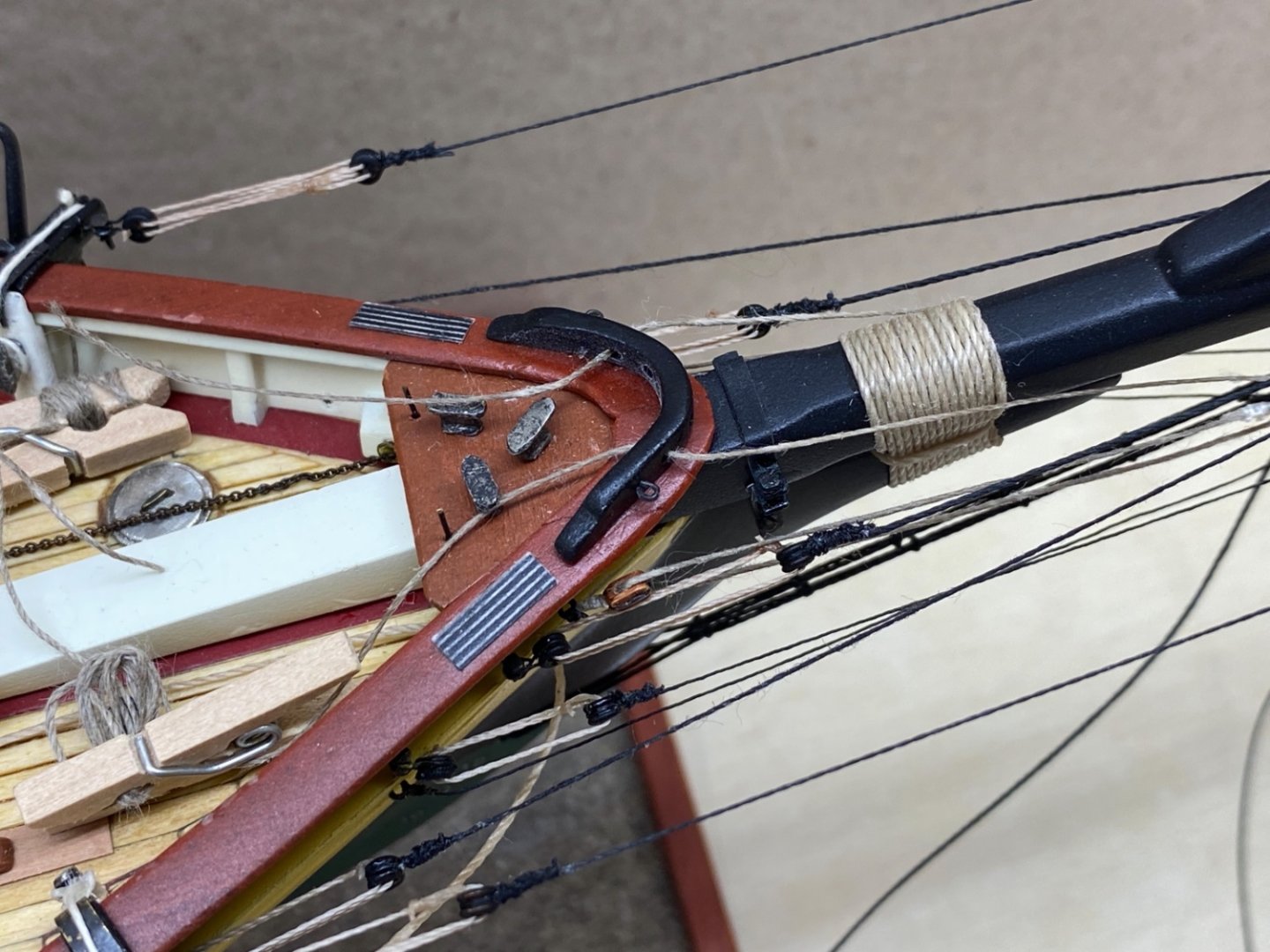
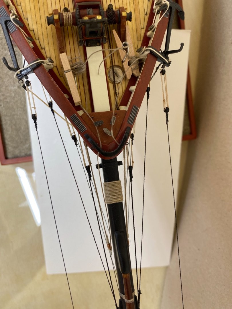
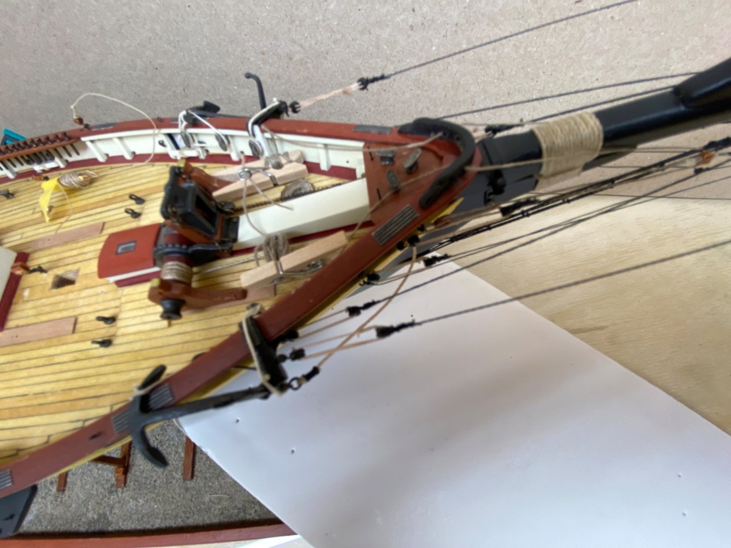
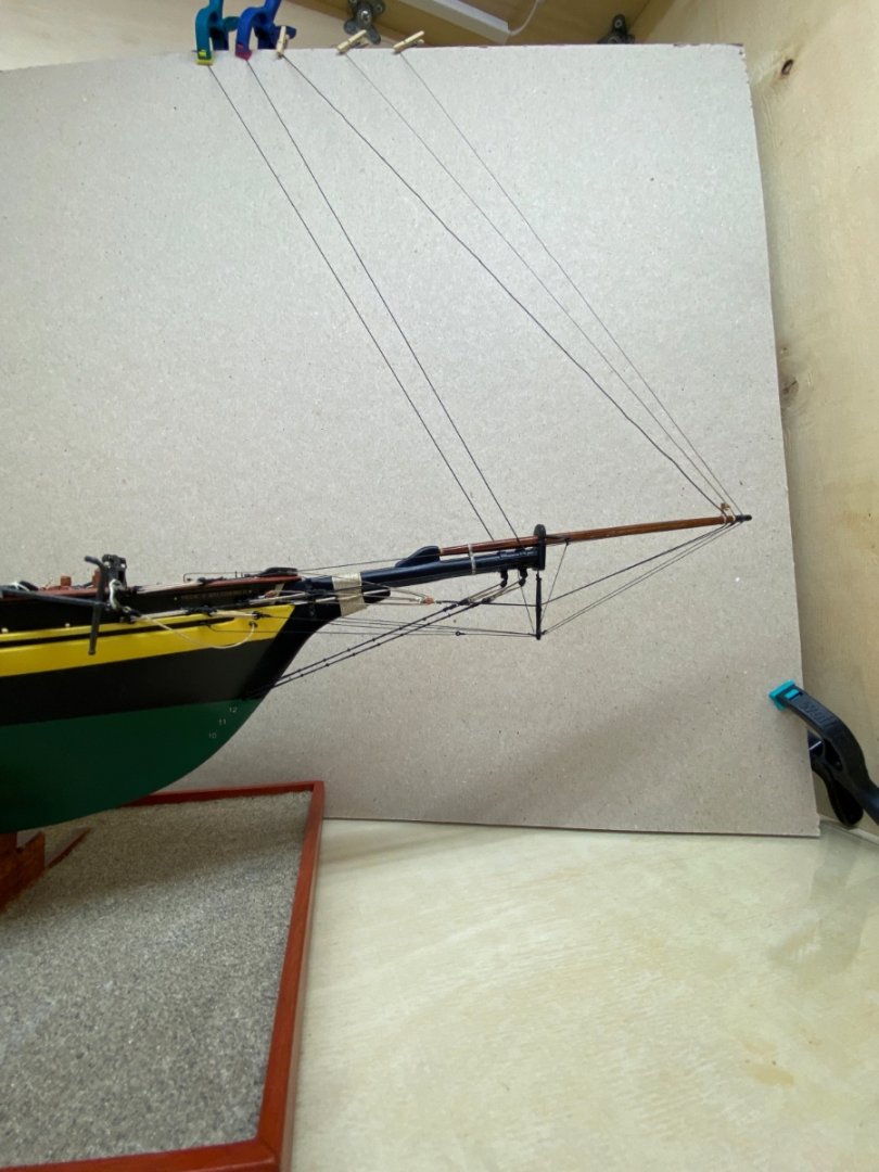
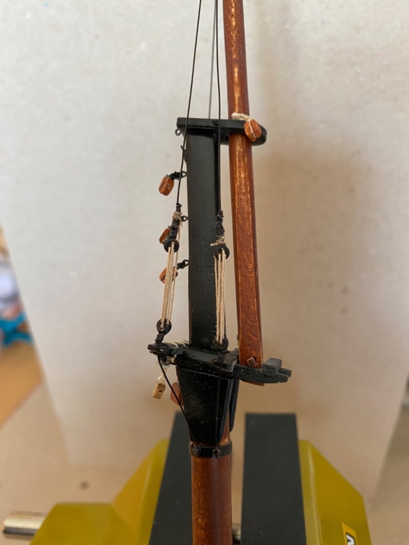
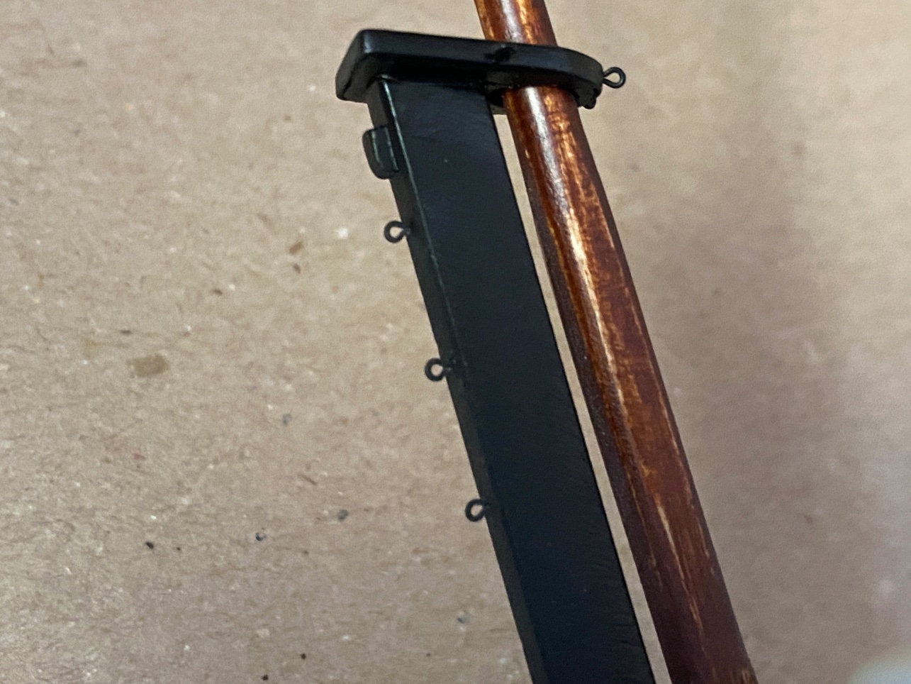
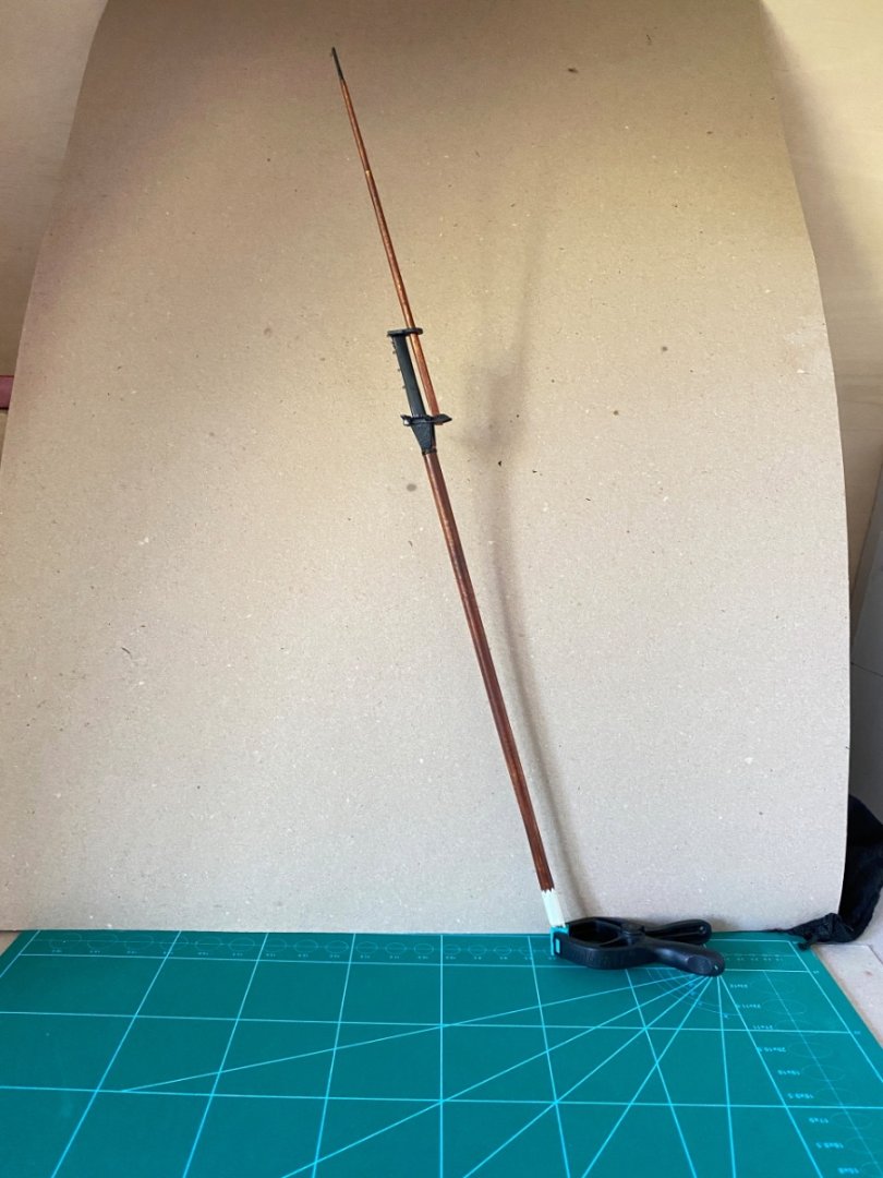
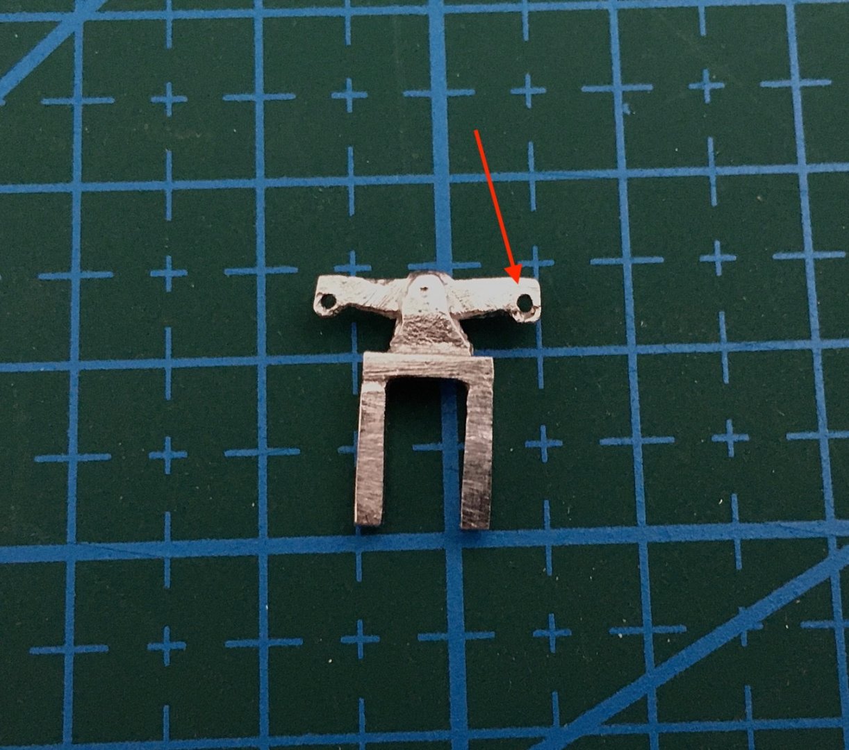
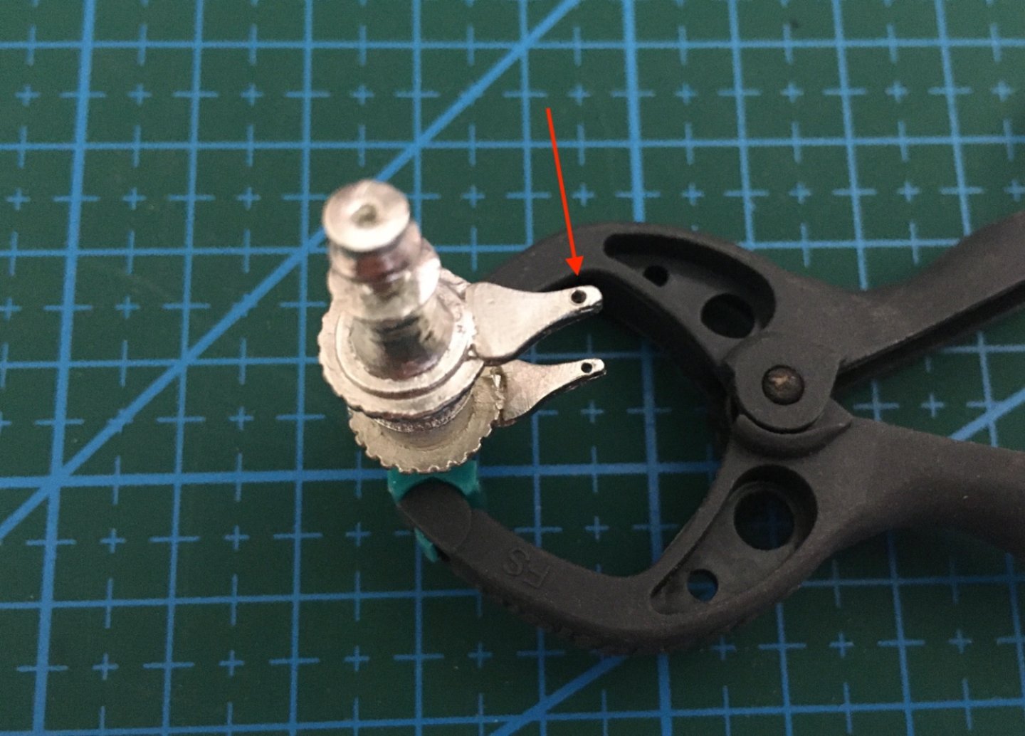
As I mentioned in the previous post, the bowsprit rigging is independent from the rest of the rigging process. Bowsprit rigging has several lines . They are all belayed to the eyebolts located at the bow and catheads except bobstay which are reeved through the holes in stem. Four of them ; Jib Boom guy, Bowsprit Shroud (guy) , Martingale Stay and Bobstays origin and end in bowsprit. However Fore Stays, Jib Stay, Fore Topmast Stay and Fore Topgallant Stay origin from the Foremast and belayed at the eyebolts at the bow. Here are some photos from the plan and a photo from the model's port bow area. Topgallant stay is directly belayed to the eyebolt without any tackle. Jib Stay and Fore Topmast Stay are belayed with tackles consisting of two single blocks. The rest have tackles consisting of deadeyes. At this stage Foremast was not installed on the deck yet, therefore the stay lines were belayed to their bow eyebolts with their tackles build. Their tips which were to be seized on Foremast were reeved through the holes in the bowsprits bees ( fore stays p/s) and at the top of the Jib Boom ( Jib Stay, Fore Topmast Stay and Fore Topgallant Stay). I started with the preparation of the deadeyes. Shackled deadeyes were fixed on a jig. Deadeyes and blocks and were stropped with suitable size threads for every line and put aside. The first rigging line build was Bobstays Jib Stay and Fore Topmast Stay lines have block tackles and they were rigged with the free tip of the line reeved through the holes in fairlead at main rail bow tip. Fore Topgallant stay followed.It's line coming from Foremast passes through the holes at the tip of the Jib Boom and Tip of the dolphin striker , then ends with a metal thimble. Another line seized to (say) starboard eyebolt passes through the thimble and ends and seized to the port eyebolt. As I said before all the other rigging lines, ending at the eyebolts at the bow, have deadeye tackles. Their shackled deadeyes are fixed with a pin passing through the shackle holes and eyebolts in between. Some of the eyebolts in the bow area are in narrow spaces and it is very hard to fix them when the eyebolt was inserted. So I removed the eyebolt and fixed the deadeye tackle with it on a jig and inserted the eyebolt attached deadeye tackle afterwards. Maybe it would have been better if the eyebolts were not installed in the first place. Here are some photos. Deadeye tackle with lanyards and pin Eyebolt removed Eyebolt inserted to the hole in the jig. Pin placed. Excess pin trimmed. Here are some photos after the lines were rigged. Free lines with blue clamps are Fore Stays. The others with mini clothes pins are Jib Stay, Fore Topmast Stay andFore Topgallant Stay. Foremast stay clamped above. The next post will be on the rest of the bowsprit rigging and preparation and installation of the bowsprit safety netting.


- 114 replies
-
- 3
-
-
- Pride of Baltimore II
- Model Shipways
- (and 1 more)
-
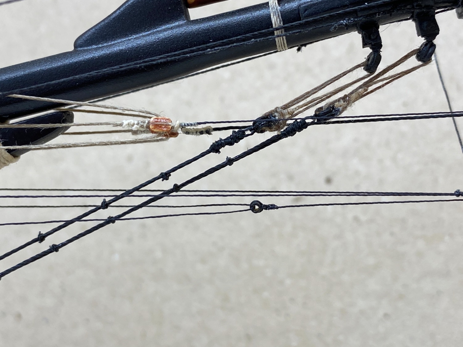
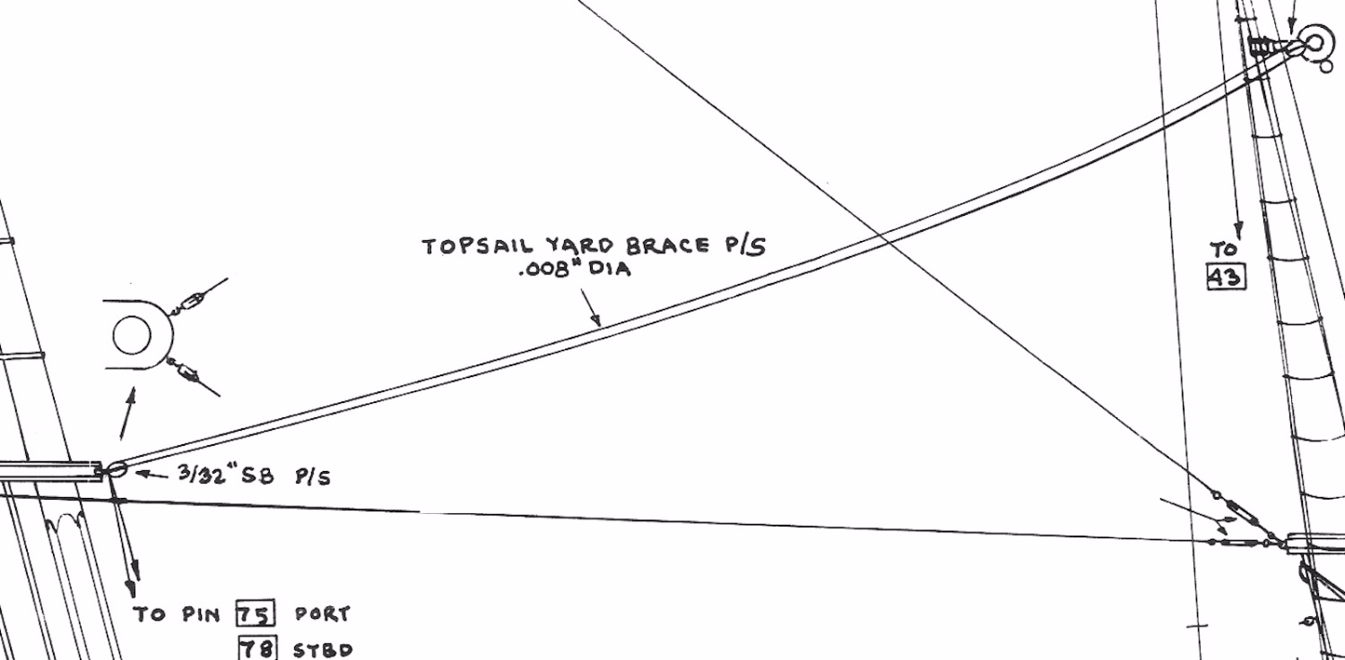
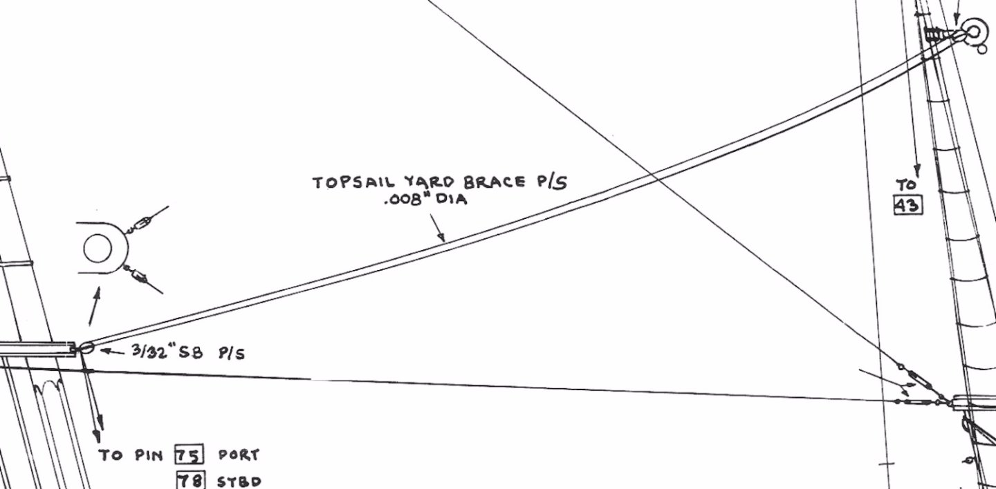
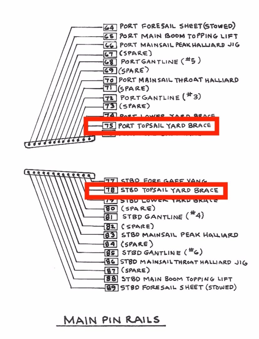
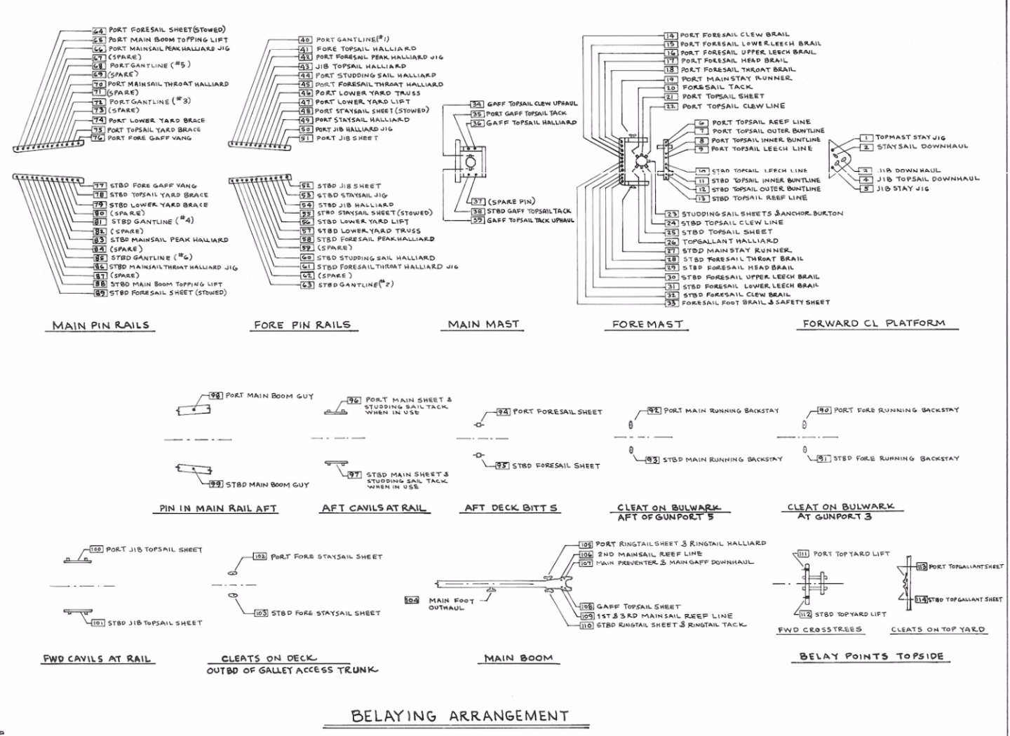
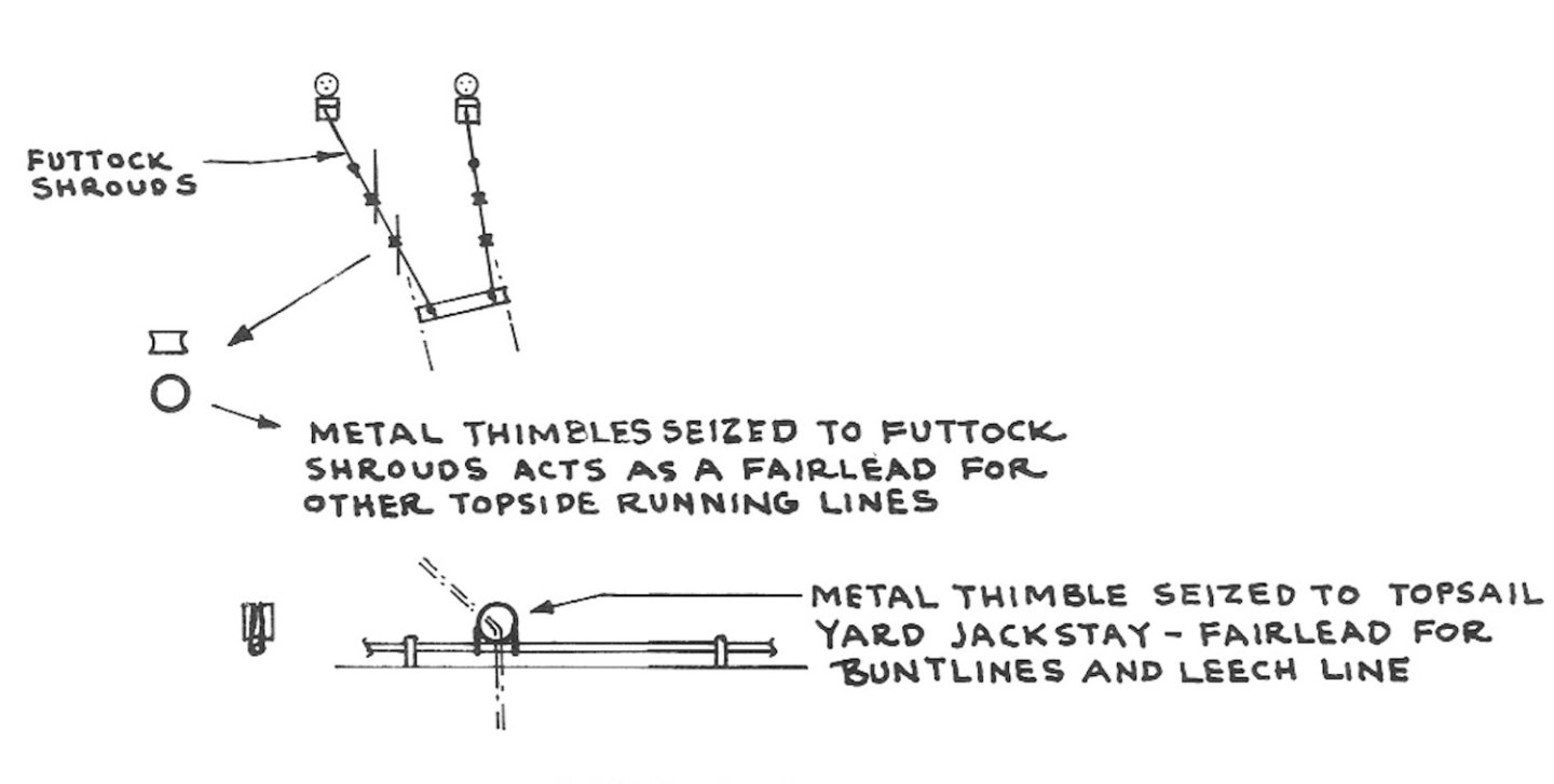
It was time to start another daunting step in ship modeling, rigging and making sails. I'll leave the sails topic to a future post now. This was my first proper rigging experience. I read a lot of articles, books and watched many videos. As soon as I started rigging process and began to be familiar with terms like blocks, deadeyes, seizing, stropping, belaying, reeving, standing and running rigging, tackle and purchase and understanding what they mean ; I quickly adapted myself into the logic of rigging. Every rigging line has a starting and ending point. This line is seldom just a line but has several structures along their course like blocks, deadeye and lanyard systems, tackles and purchases ( POB II has some jigs unique to her), turnbuckles etc. Plans of POB II clearly show the origin and belaying points of every rigging line quite nicely. Let us check one of them. The rigging lines for fore top yard braces in the plan photos below. In the first photo you can easily see the origin of the line : A SB (Single block with becket) seized to an eyebolt at the fore side of main mast cap. The line first goes forward to fore top yard single brace block, reeves through it. Then comes back to the SB it originated, reeves through it and goes downwards to the belaying pin number 75 on port and 78 on starboard and belayed. Actualy this rigging line was the first line I made in the rigging process of POB II As I said before, once you are familiar with the logic of it, rigging is pretty much straight forward. Also I found this step enjoyable and fun as a complex structure unfolds itself slowly once you start rigging lines one by one. Here is the photo showing all the belaying points. My rigging plan was as follows , To finish every detail ( Footropes, stirrups, fore topmast shrouds etc ) and strop every block on the masts, yards, gaffs and main boom. To prepare every rigging line (except ringtail sail, fore top gallant sail and some studding sail lines) with all its blocks and place them in small plastic bags with a note of the details in it. Start rigging those lines to the origin points on masts and yards. Install yards to foremast. Install masts to deck. Start belaying lines from the bases of the mast. Then moving to bow, stern, port and starboard belaying points. Here you have to rely on your common sense and think like a chess player. Rigging of bowsprit is a bit independent. The rigging direction is reversed in some standing lines like fore stays, jib stay , fore topmast stay and fore top gallant stay which were seized to foremast and fore topmast later (Of course this was how I did it and by all means not the only way to do it). Preparation and installation of the sails. I decided to use furled sails as the model will be on the building ways as if during a maintenance period and open sails will be unlogical. Preparation and installation of rope coils to belaying points. Main and fore shrouds on port and starboard. Main rail life line with stachions. Flags and pennant. Unfortunately the quality and quantity of the blocks given by the kit were poor. There were only 3/32 single or double blocks and 1/8 single and double blocks. However there were also 1/32 and 1/16 single and double blocks on the plans. There were also 1/8 triple blocks for throat halliards.As third party brand suppliers for those type and sized block is close to none in my country and ordering them from USA or UK was out of question due to shipping and customs costs and mainly to currency exchange rates these days, I had to scratch build them. The other issue was the size of the rigging lines given by the kit. There were at least 6-7 sizes of threads were used in the plans. However only two sizes were available in the kit. The smaller sizes of black and tan colors, both cotton and nylon were easy to find in sewing supply stores. Although larger sizes of nylon black thread was easy to find, larger sized nylon tan color was not possible. Unfortunately I discovered embroidery supply stores after the model was finished. Almost every sized color nylon thread can easily be found there. Another problem , probably to my wrong doing something, was the fuzziness in the threads. No matter how many times and how well I bees waxed them and squeezed them under heat, I could prevent the fuzziness . I am sure there will be some suggestions on this matter. Let's start with the structures on the masts and spars. Preparation of the stirrups for foot ropes. Thimbles of the fore lower yard Main mast from different angles Starboard view. Peak halliard blocks Looking fore from stern. Throat halliard triple block in the middle. Gantline block, boom topping lift block and signal flag thimble starting from middle towards sides. Looking from fore towards aft. Fore top yard brace lines in bags Main mast cap fore side Fore mast have way more structures than main mast. Fore top mast shrouds are now of them. I used 0.2 mm black wire as shroud lines. I regretted it after the job was done and gave up the idea of using 0.2 and 0.3 mm black wire in some of the standing rigging lines. Topmast shroud lines, futtock shrouds, deadeyes and lanyards (starboard view) Looking from aft to fore Ratlines (starboard view) Starboard view Looking from aft to fore Blocks on the fore topmast shrouds fore line Looking aft from fore Here are some photos of the prepared lines in tagged plastic bags. Two sizes of black wire seen were not used later. So the first two steps of the rigging process was completed.


- 114 replies
-
- 3
-
-
- Pride of Baltimore II
- Model Shipways
- (and 1 more)
-
Thanks a lot Yves. I like to inform you and future viewers about the index list I started to record in Post #1. Page number/ Post number/Post subject are given in ascending order of the post numbers. I tried to link them to their exact position in the blog, but I could not do it. I’ll try again later.
-
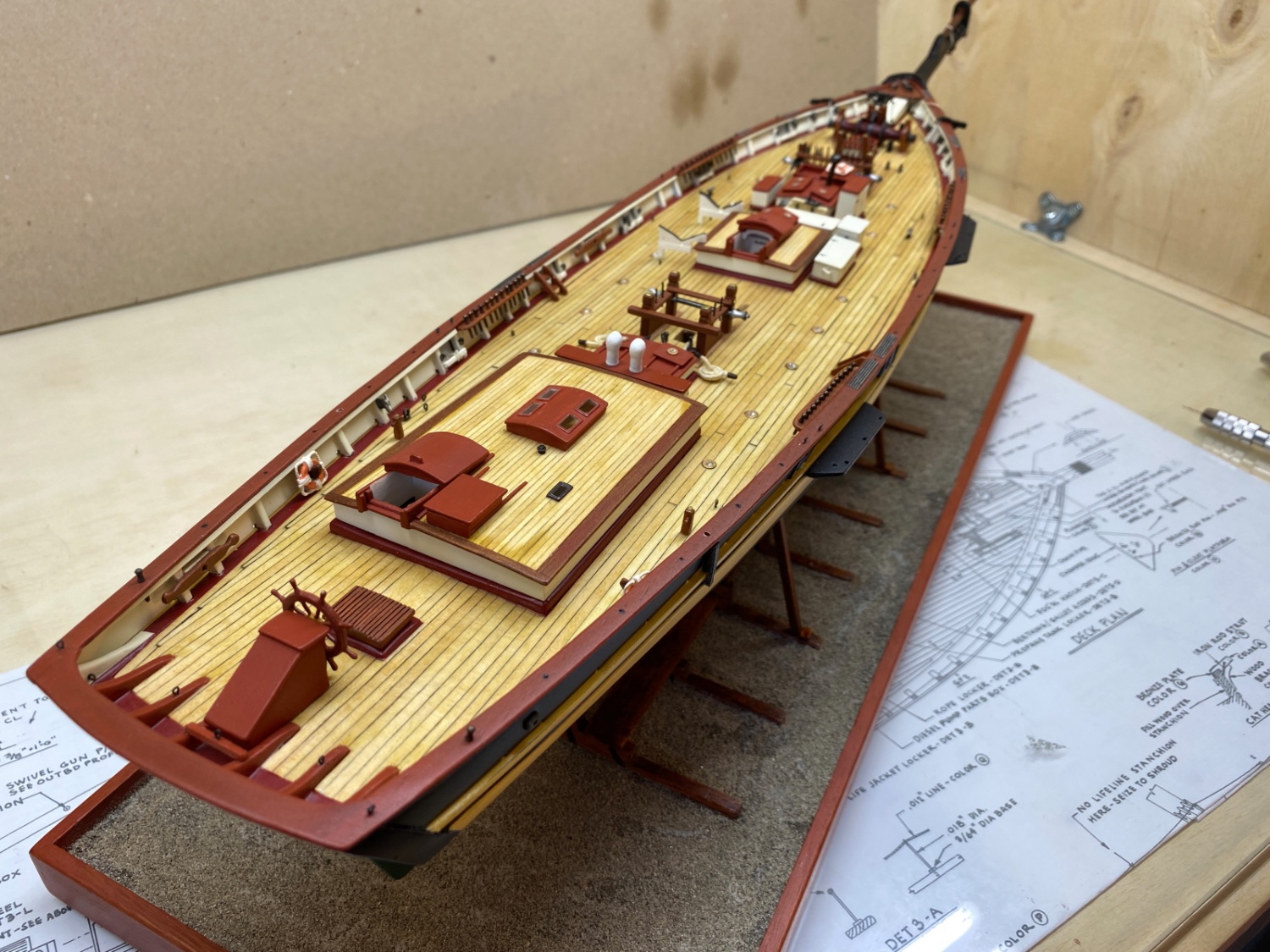
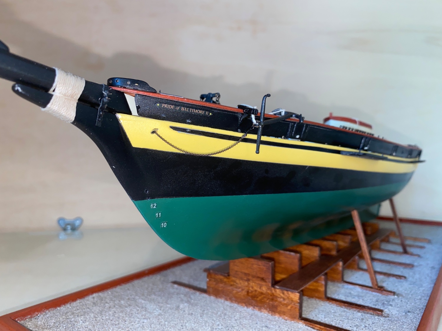
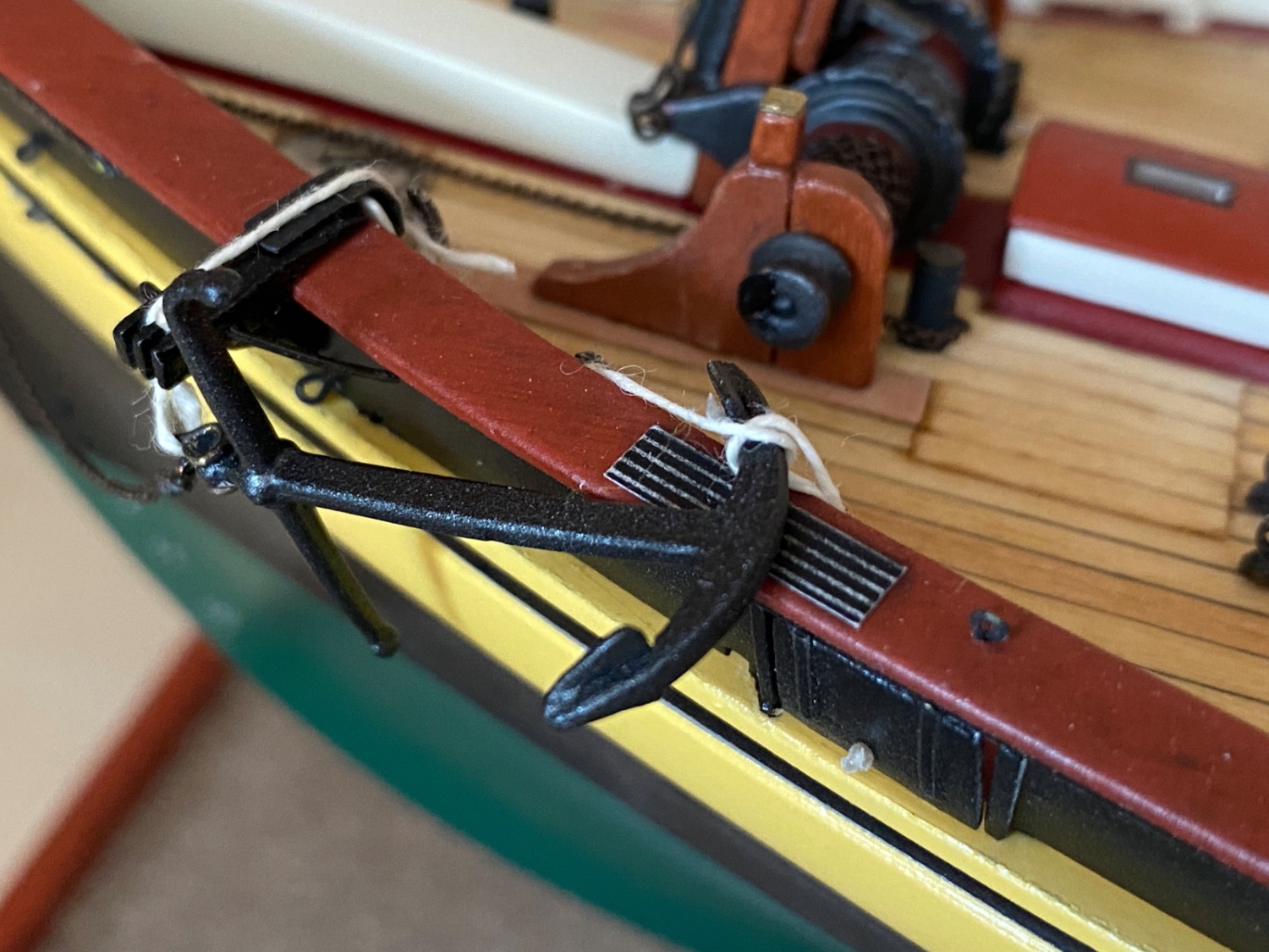
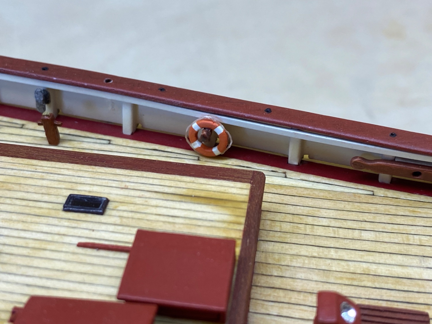
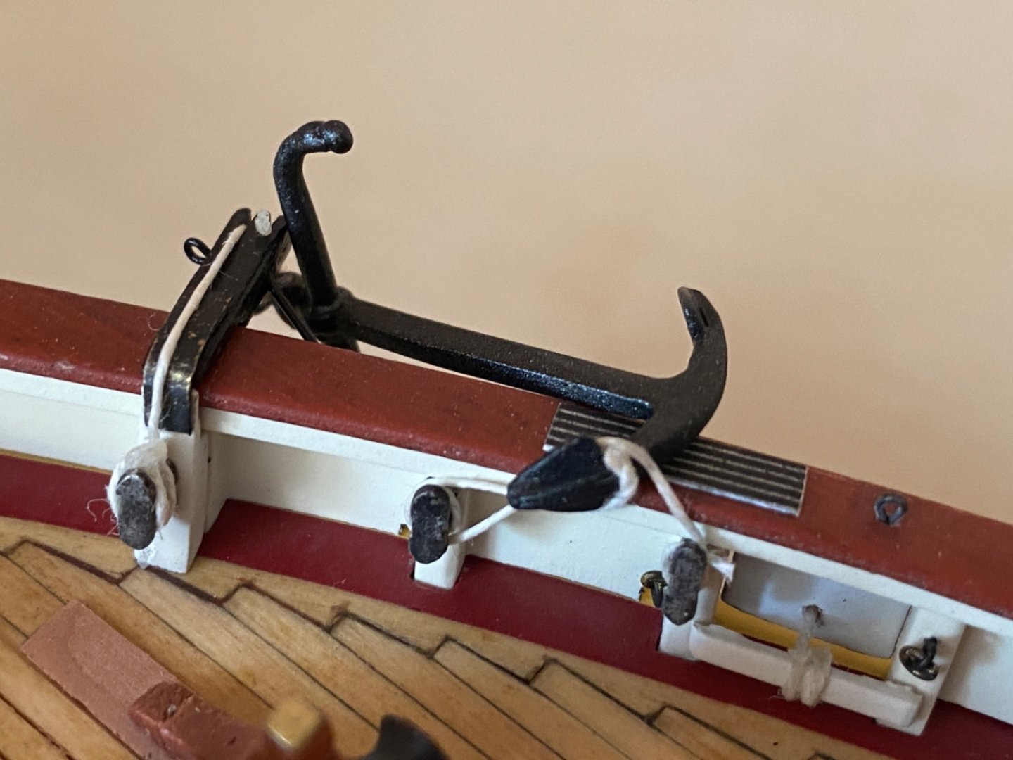
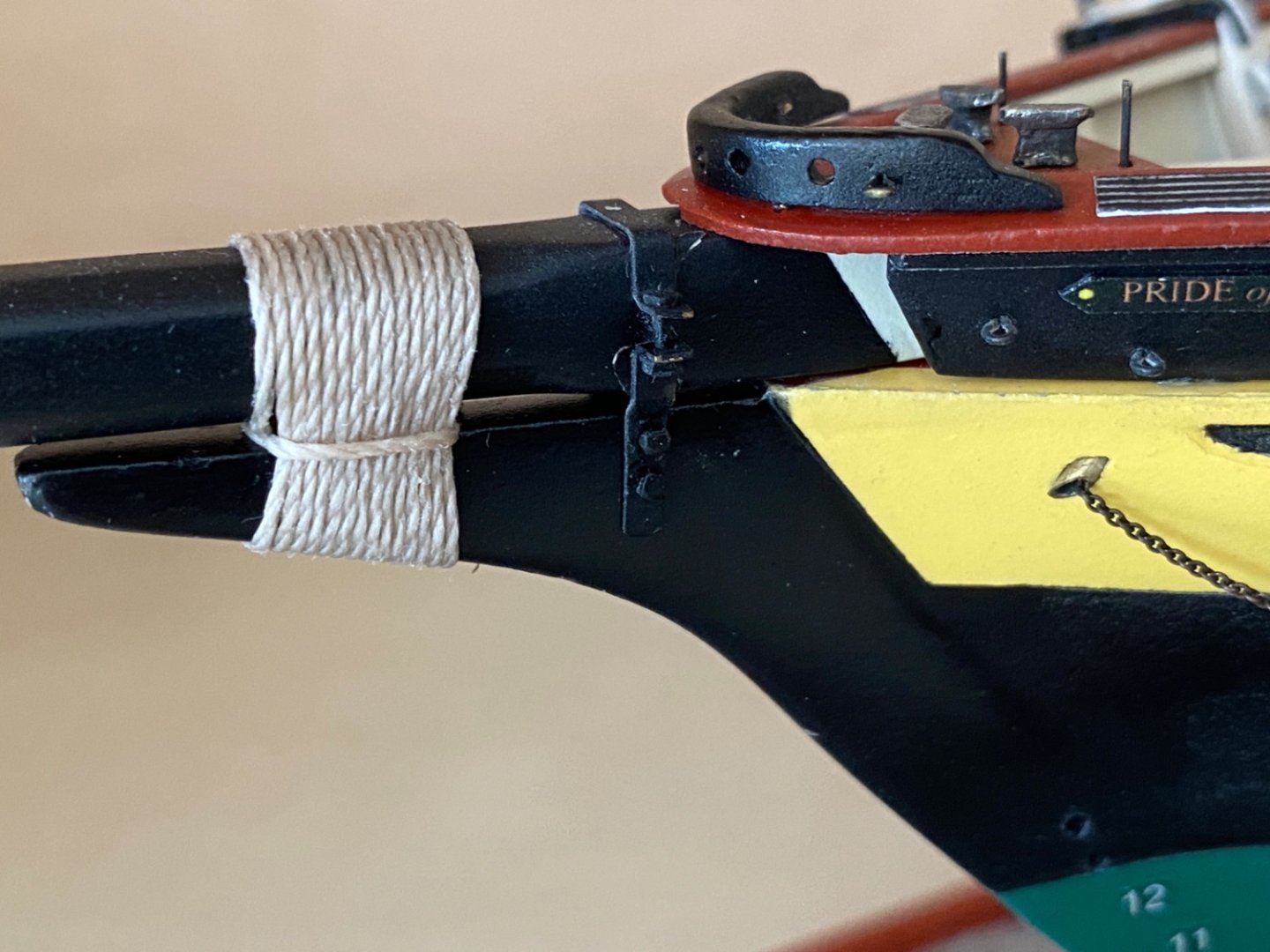
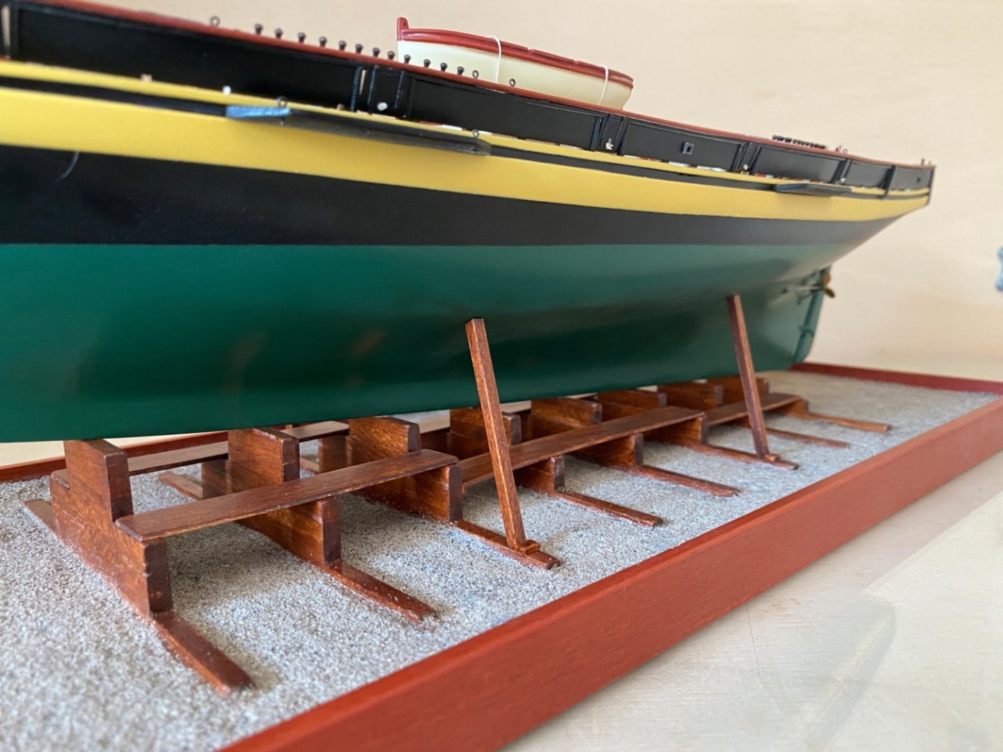
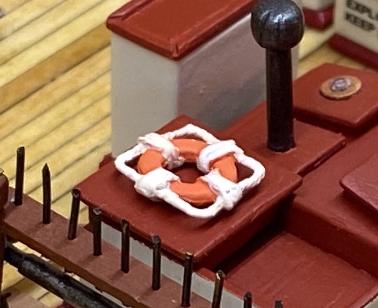
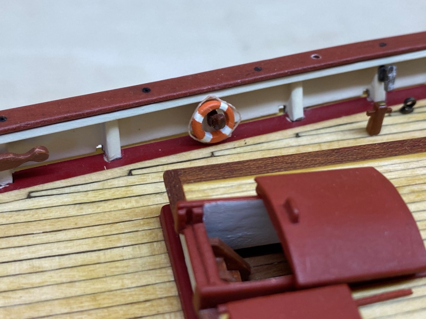
It is now July, 2022 and the 23rd month of the real build time. The final satin coats were airbrushed to the hull after the 4 channel platforms and 2 fake gun stocks were glued to it. Commercial satin varnish diluted with lacquer thinner with 1:1 ratio was airbrushed. 2 coats were applied. An extra coat was airbrushed to transom in order to cover the lettering decals and improve their look. Here are some photos of this step. After waiting for three days for the cure of the satin coats, I started to install all the deck. bulwark and main rail structures. At this stage the structures around the mast holes were temporarily dry fitted for demonstration. Here are photos from the first structure installation stage. In the first two photos you can see the boat stowage cradles with gasket material glued to inclining sides. Here are photos starting from bow and fore deck. You can notice that the anchors with chain and ropes were not installed yet. The life rings seen on the photos were the kit's stock which were replaced with the scratch build ones later (Post #71). Step pads on the main rails are thin papers with the design printed on and later weathered by sanded pastel paint dust. Closeup photos of certain areas of the deck. Photos of the hull, transom, bowsprit. As you can the model was mounted on the building ways platform. The model was not removed from it again (meaning everything went as planned !) You can also see the anchor chain and ropes were installed through hawse pipes. Some more closeup photos of the deck structures. The whole deck photo at this stage The photos of the model a couple of days later with some additions made. Here in this photo you can see the figure at the bowsprit cap. It was printed on 300 grams photo paper and glued in place. Bowsprit gammoning was made. Anchors in final position and place. The anchor chain (port) and rope (starboard) were also placed in final position and their free tips were inserted in the chains pipes and rest below the deck. The temporarily dry fitted fife rails, bilge pumps and the second fire hyrant were removed and the special planks with insertion holes can be seen also in the following photos. The model on building ways at September 1st, 2022. jibboom spreaders and dolphin striker were installed to bowsprit cap. Some photos of the hull at this stage .


- 114 replies
-
- 5
-
-
-
- Pride of Baltimore II
- Model Shipways
- (and 1 more)
-
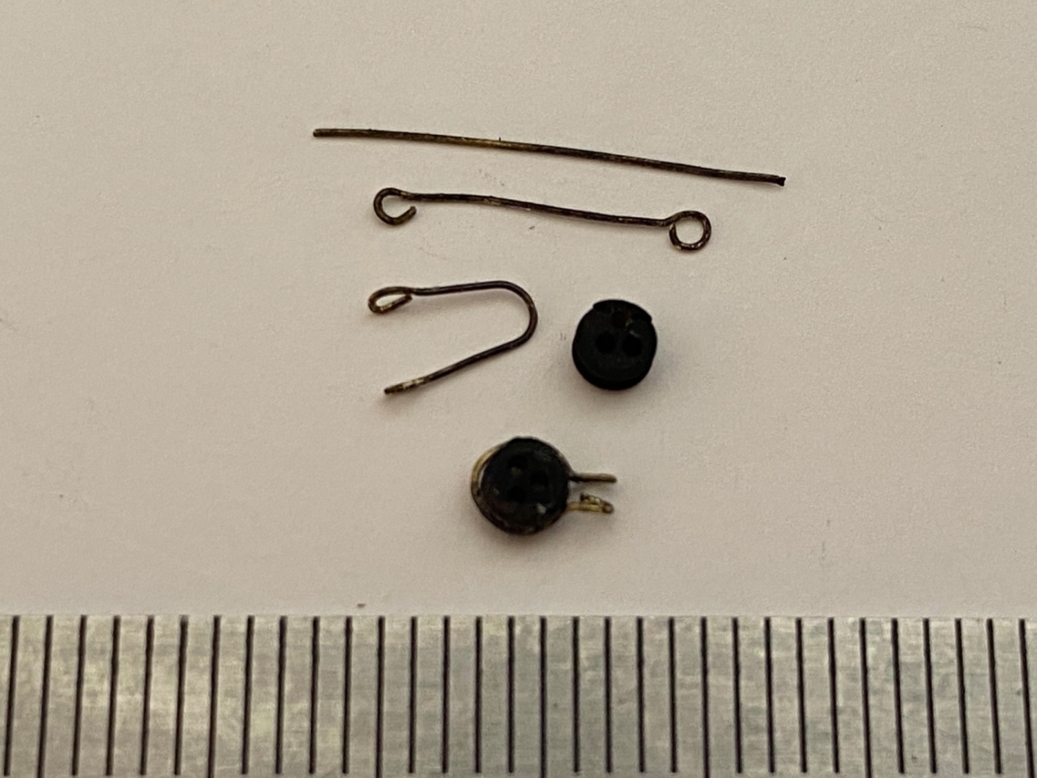
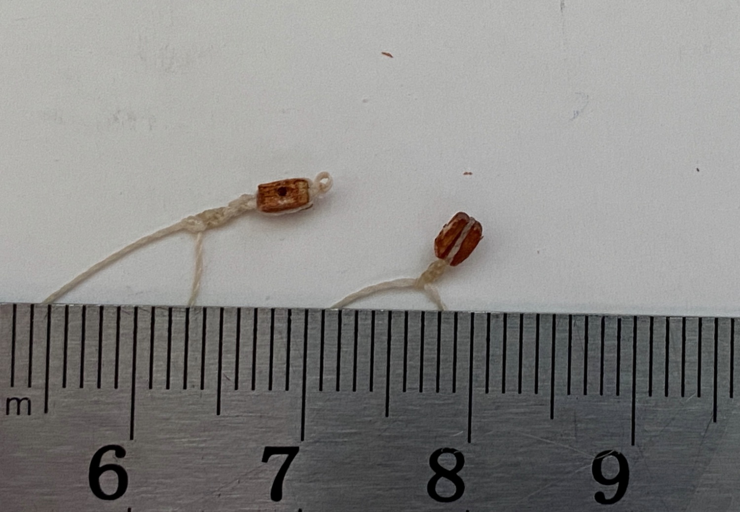
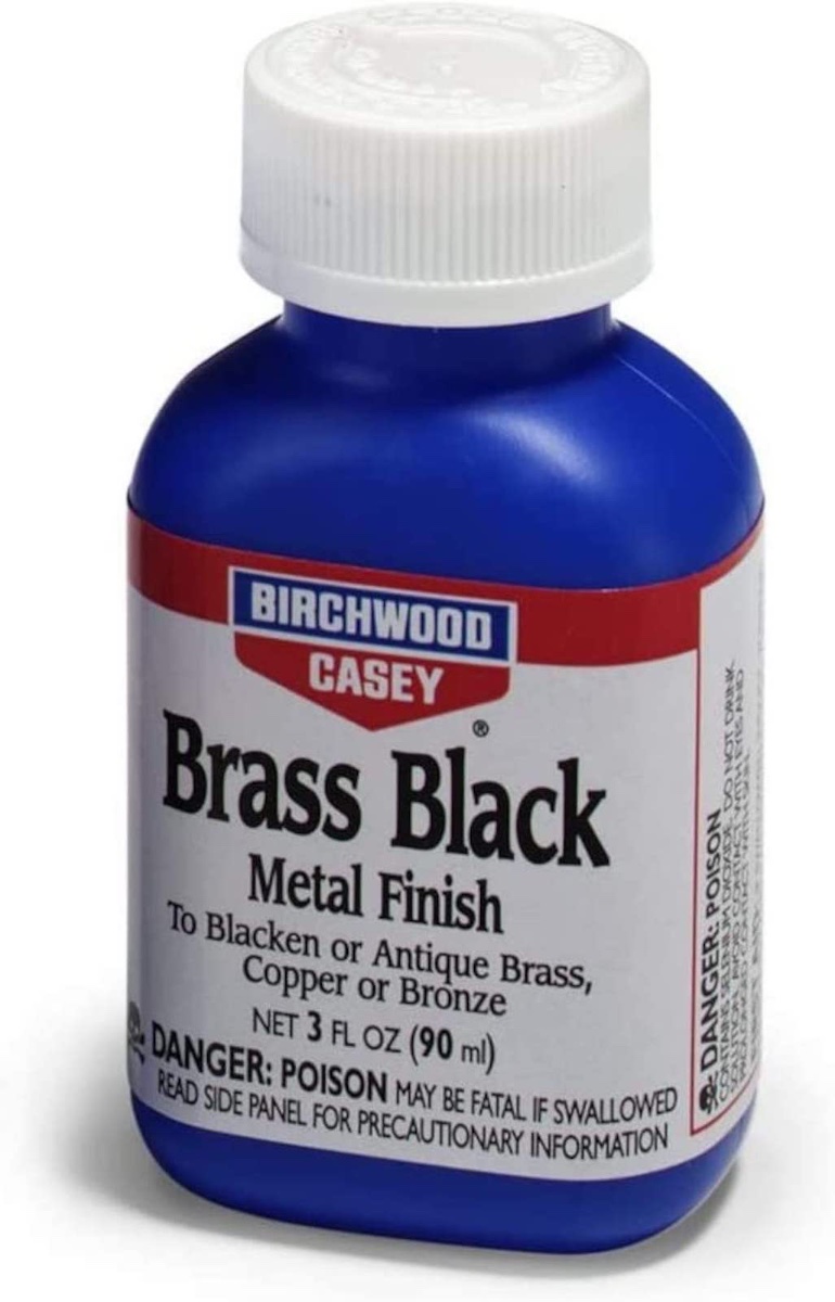
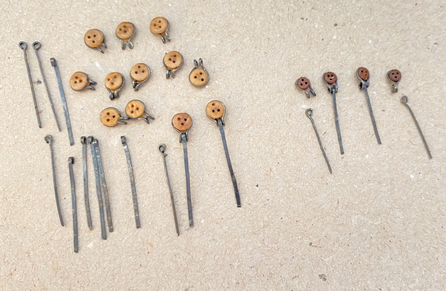
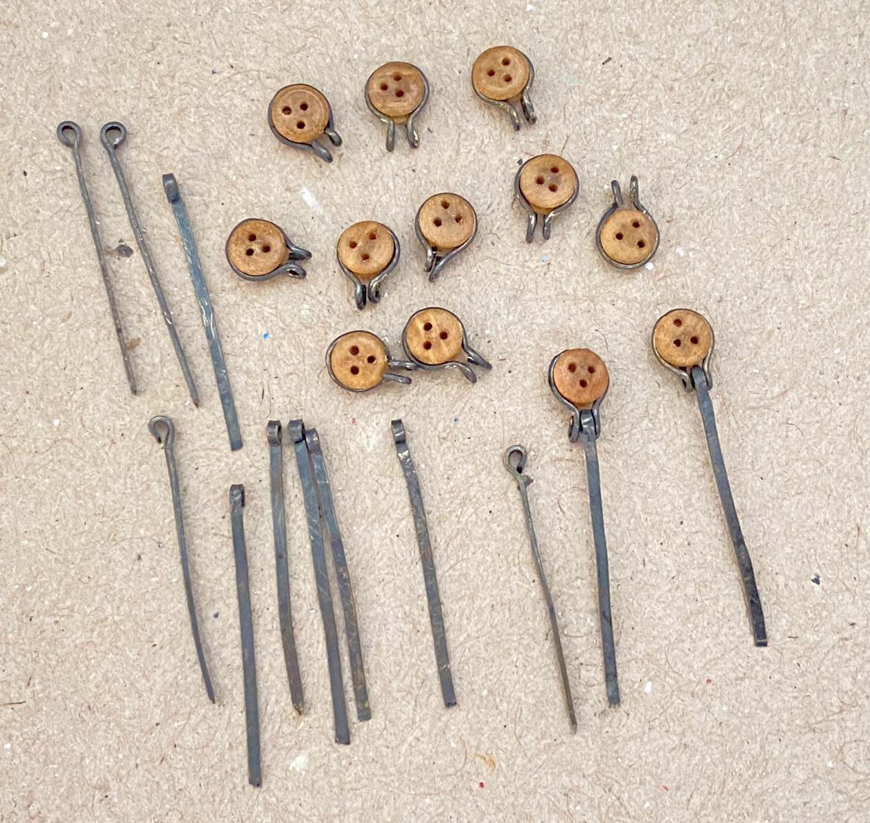
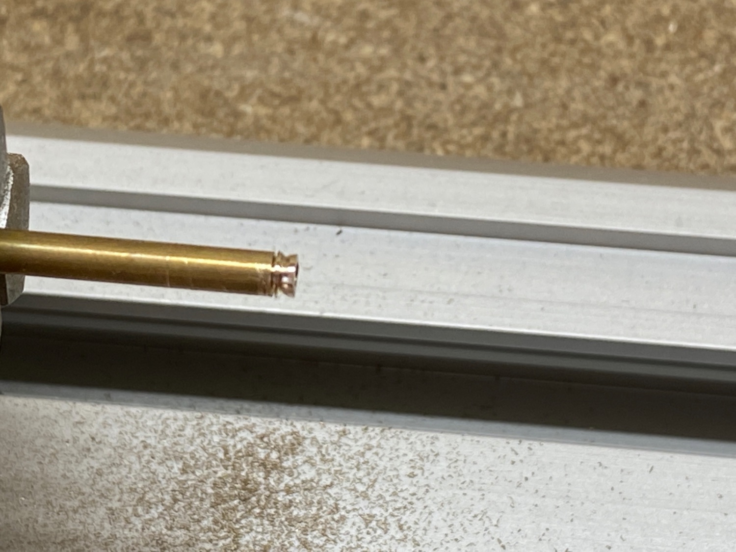
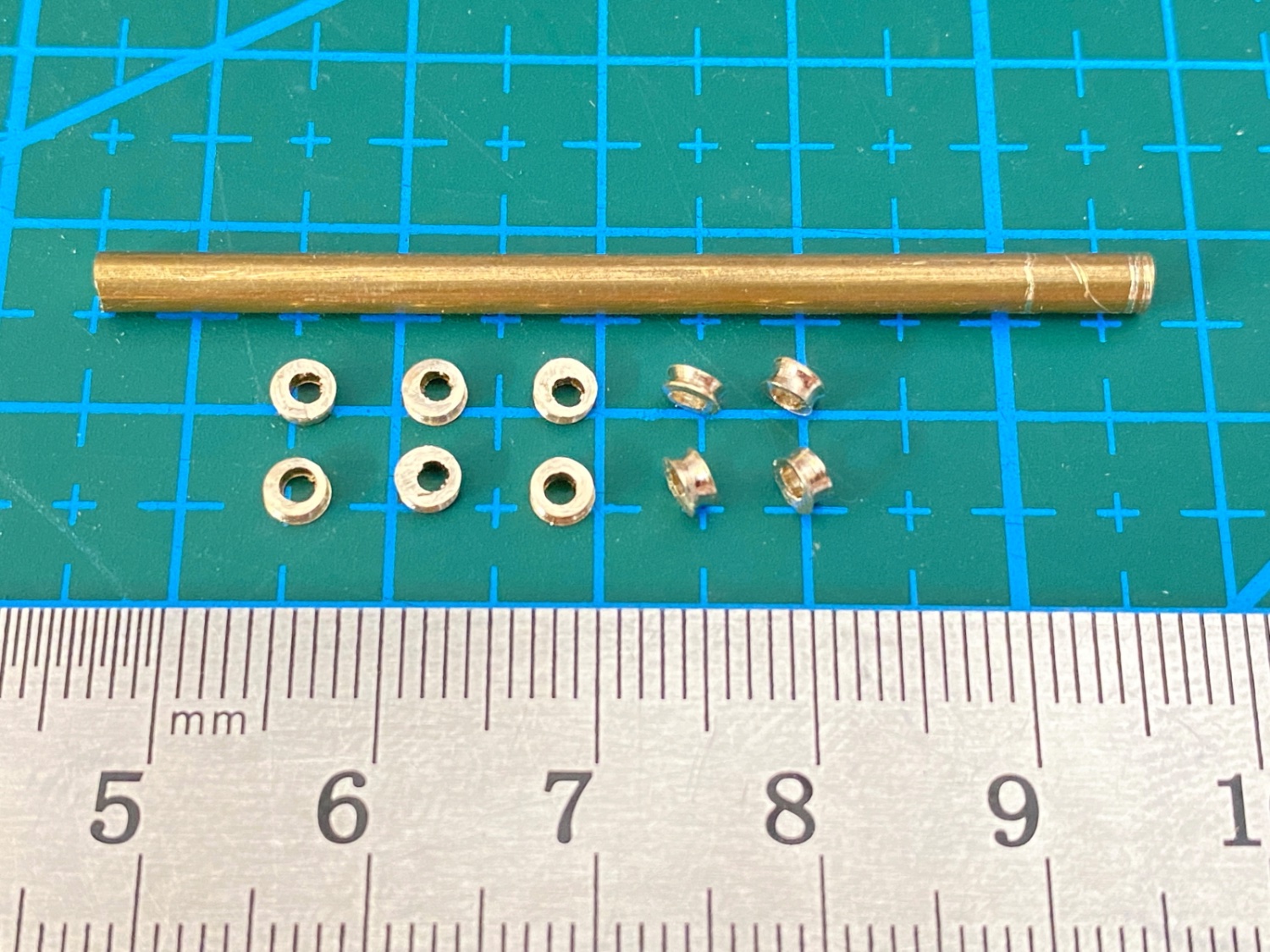
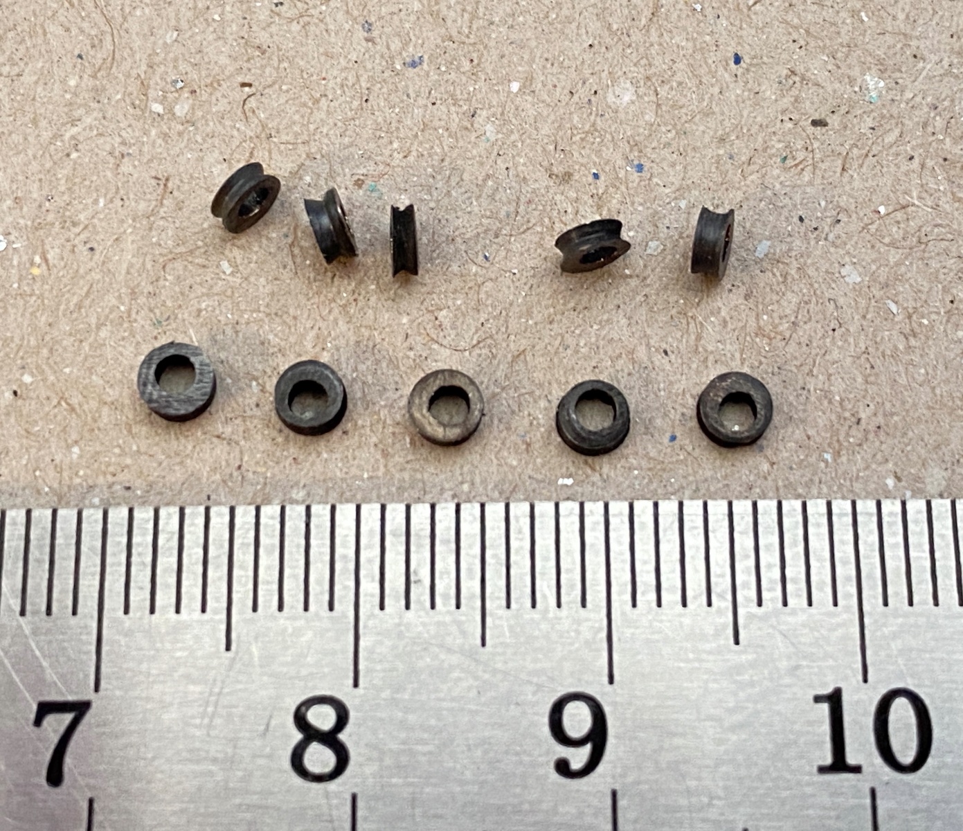
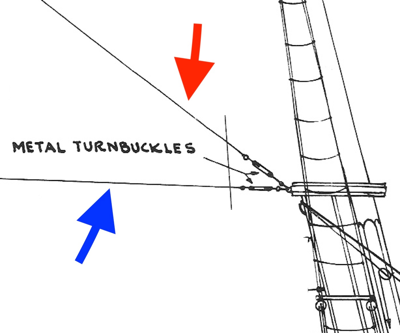
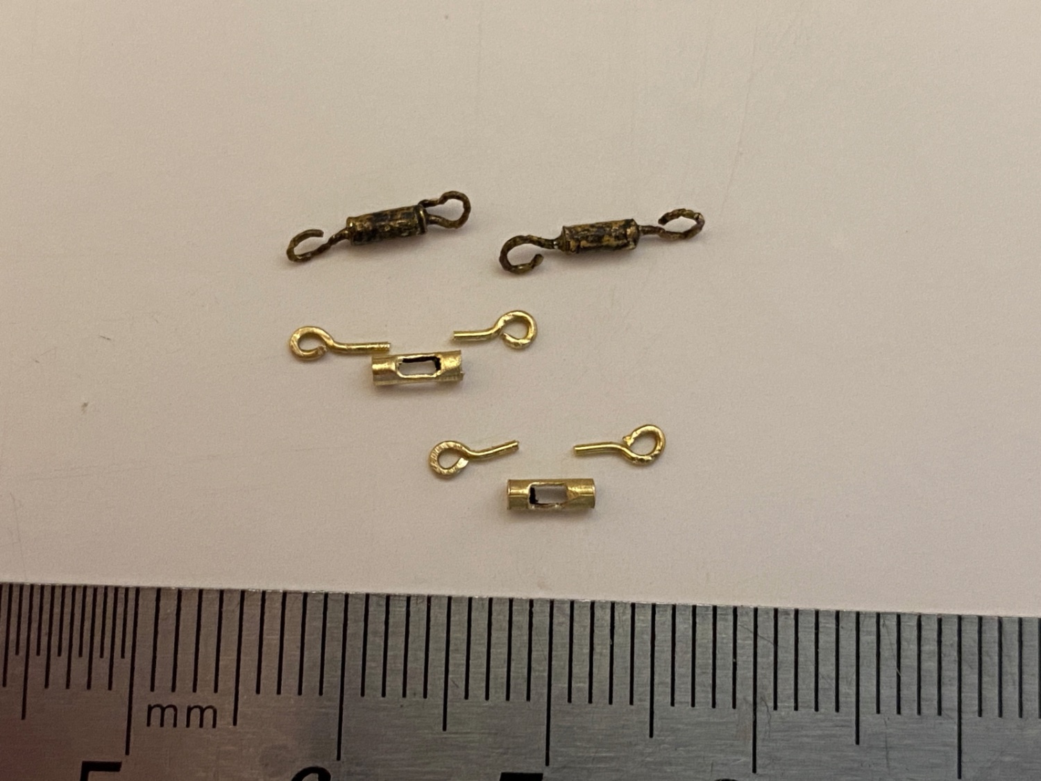
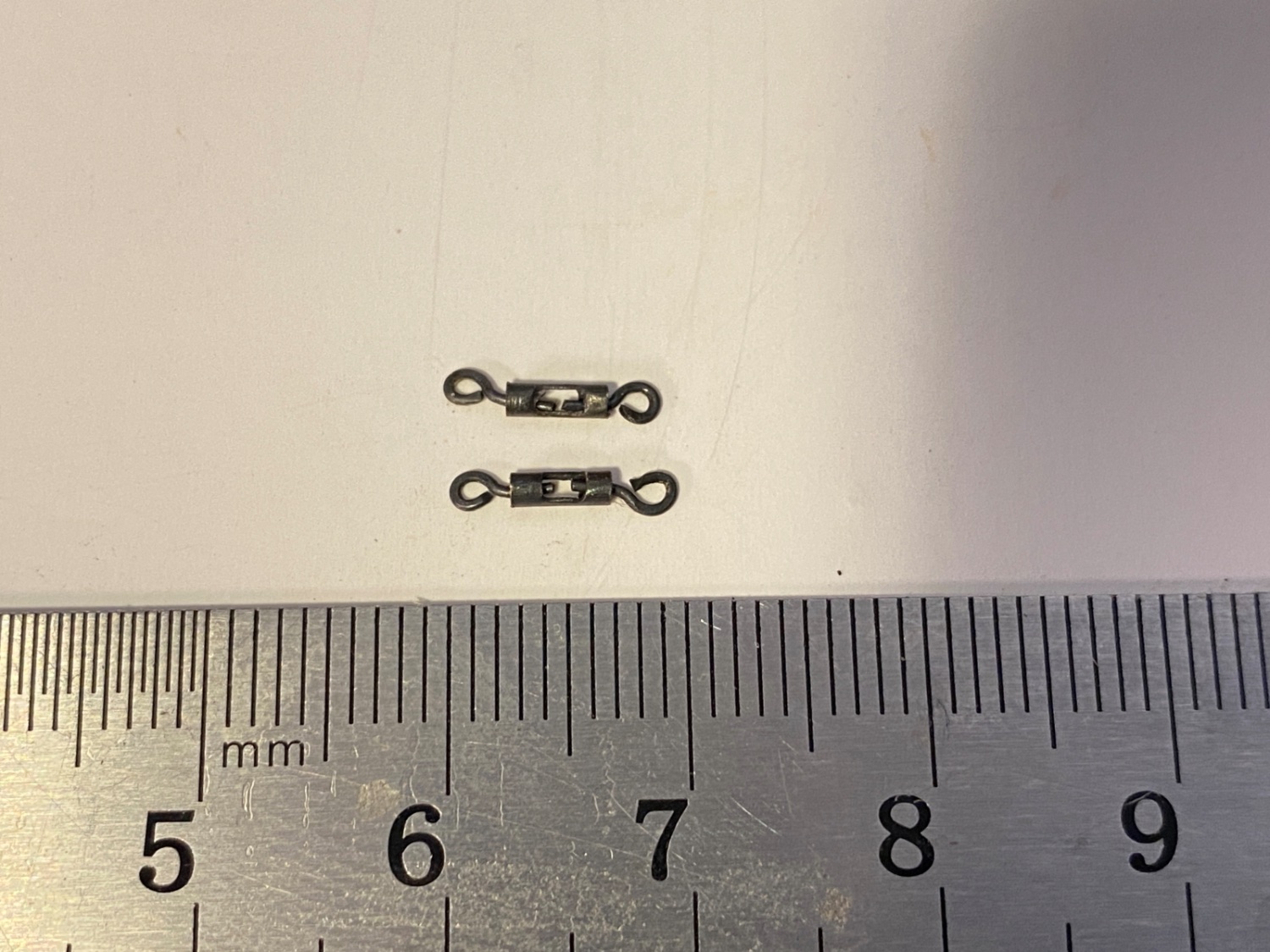
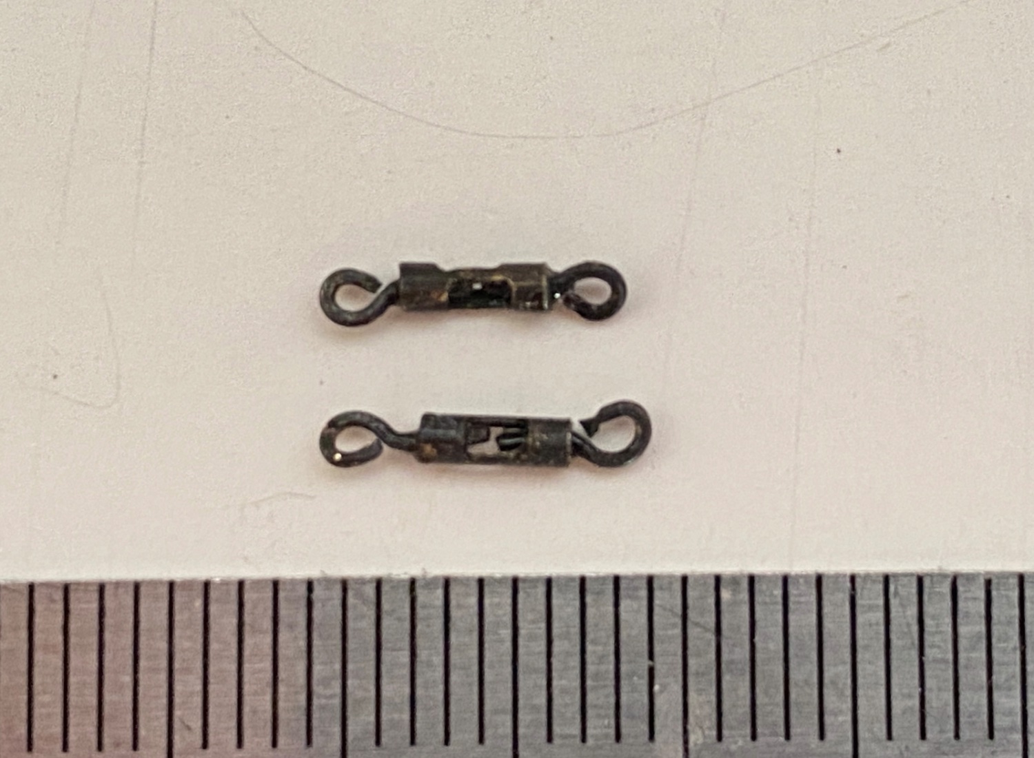
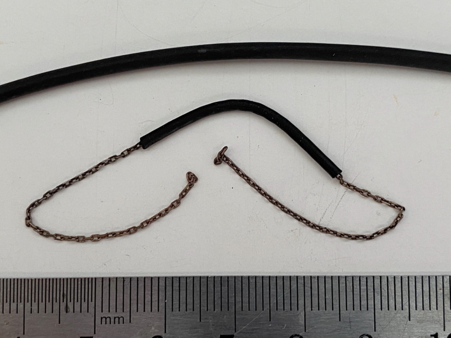
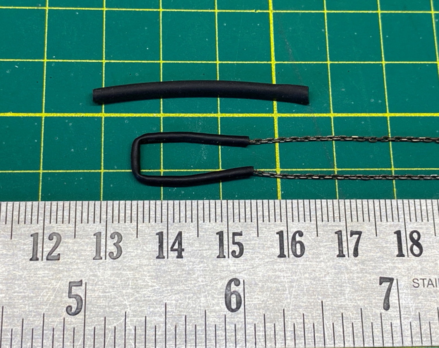
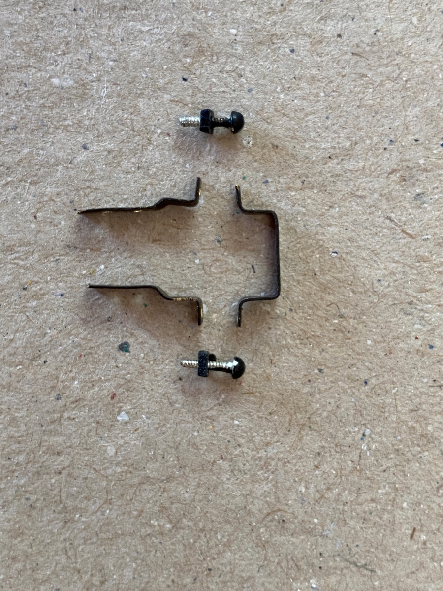
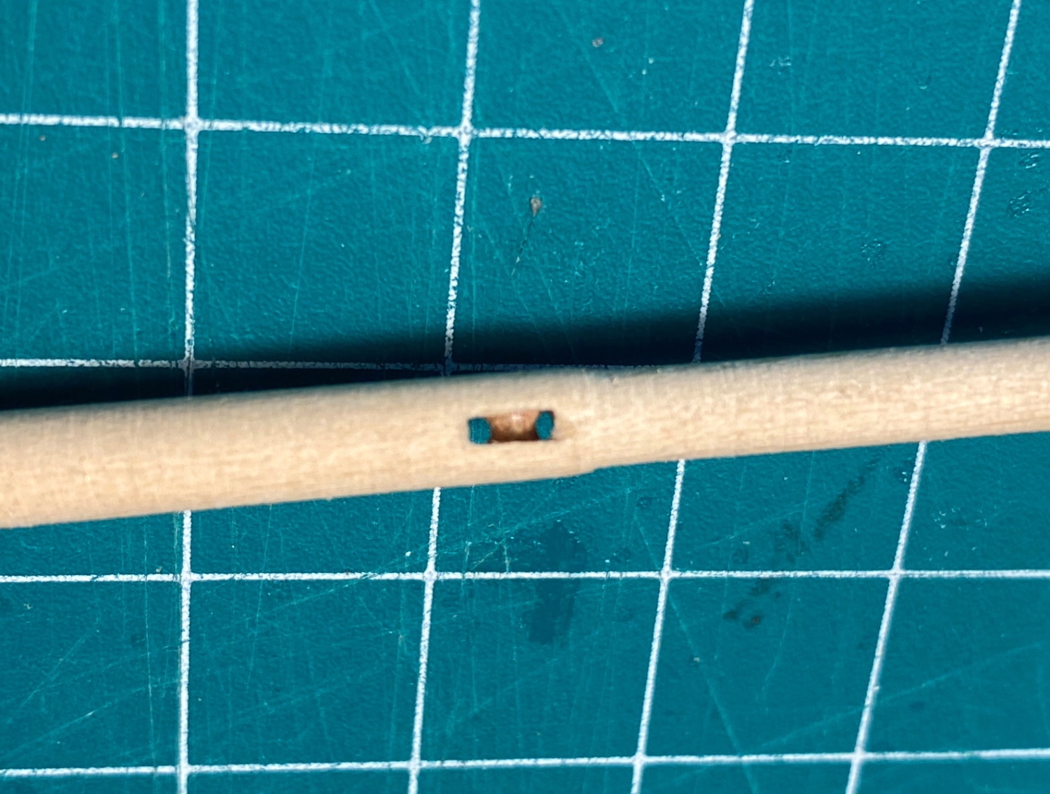
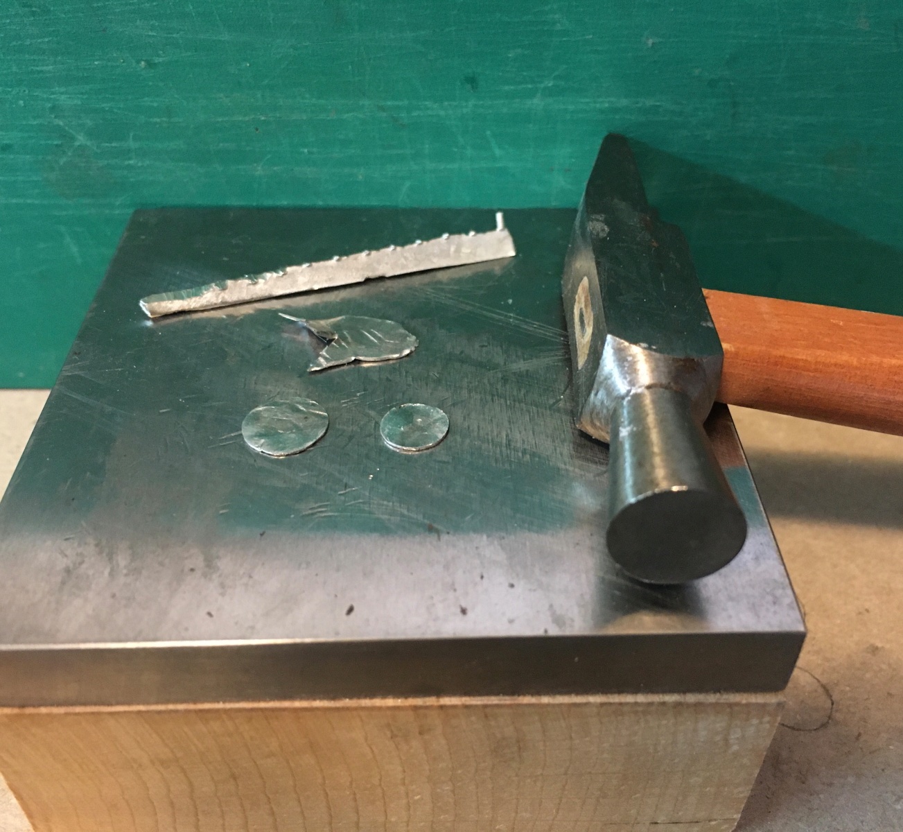
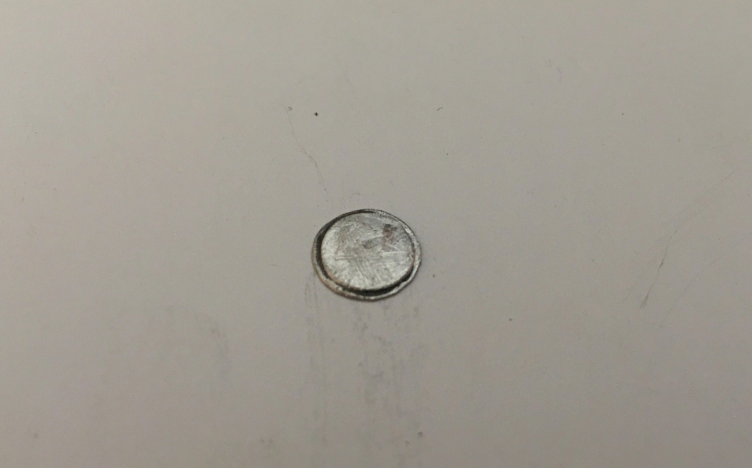
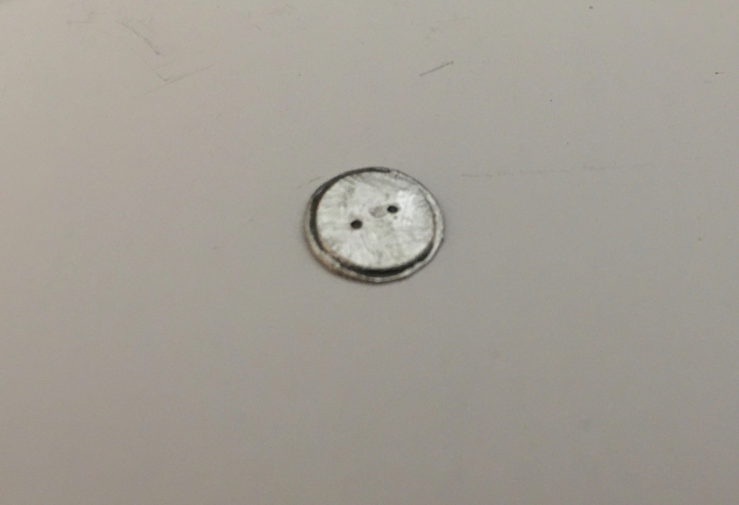
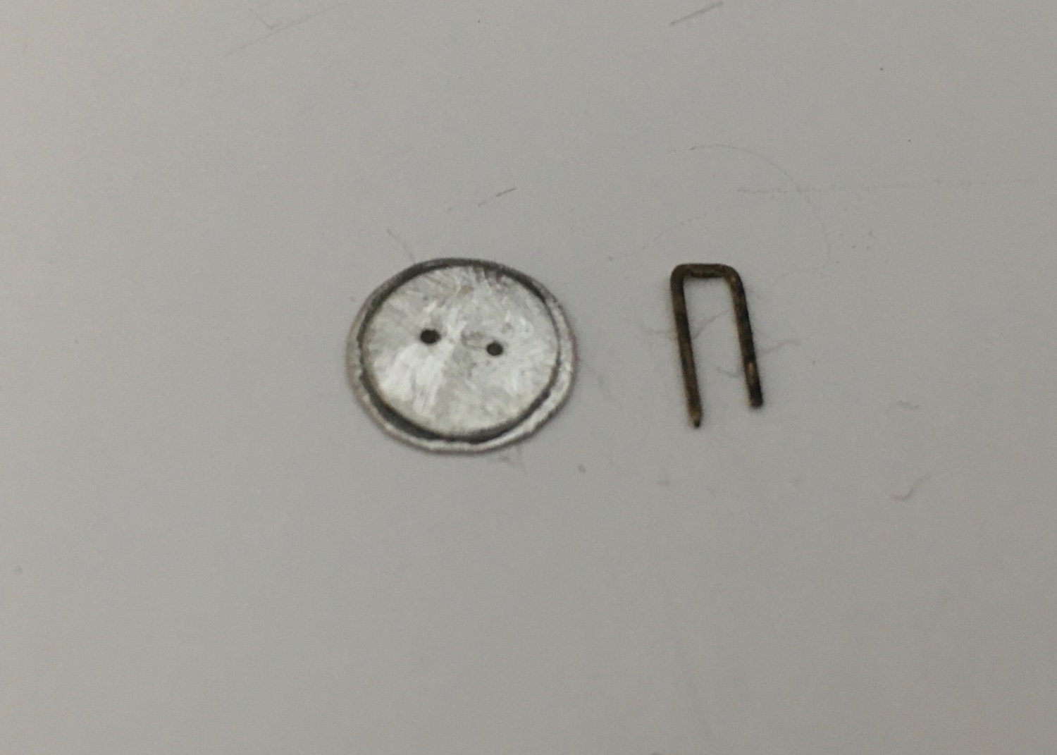
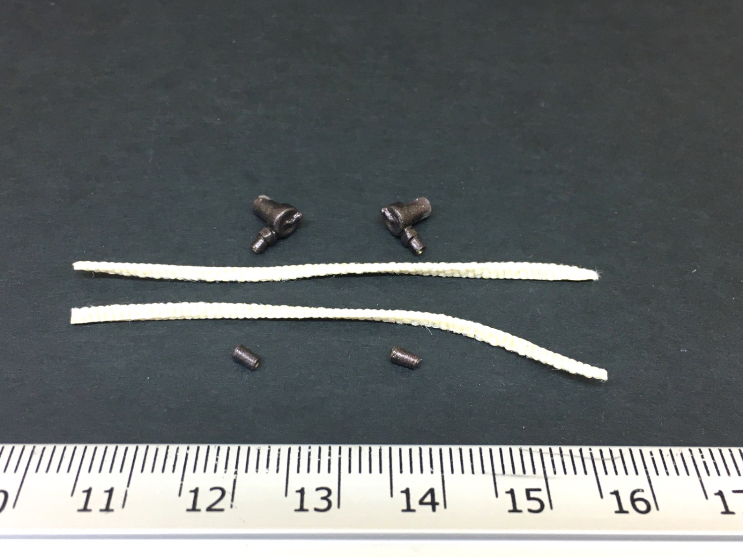
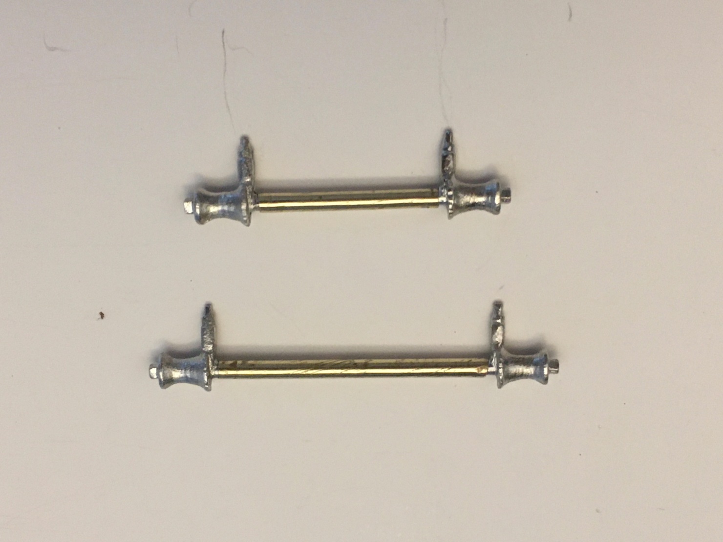
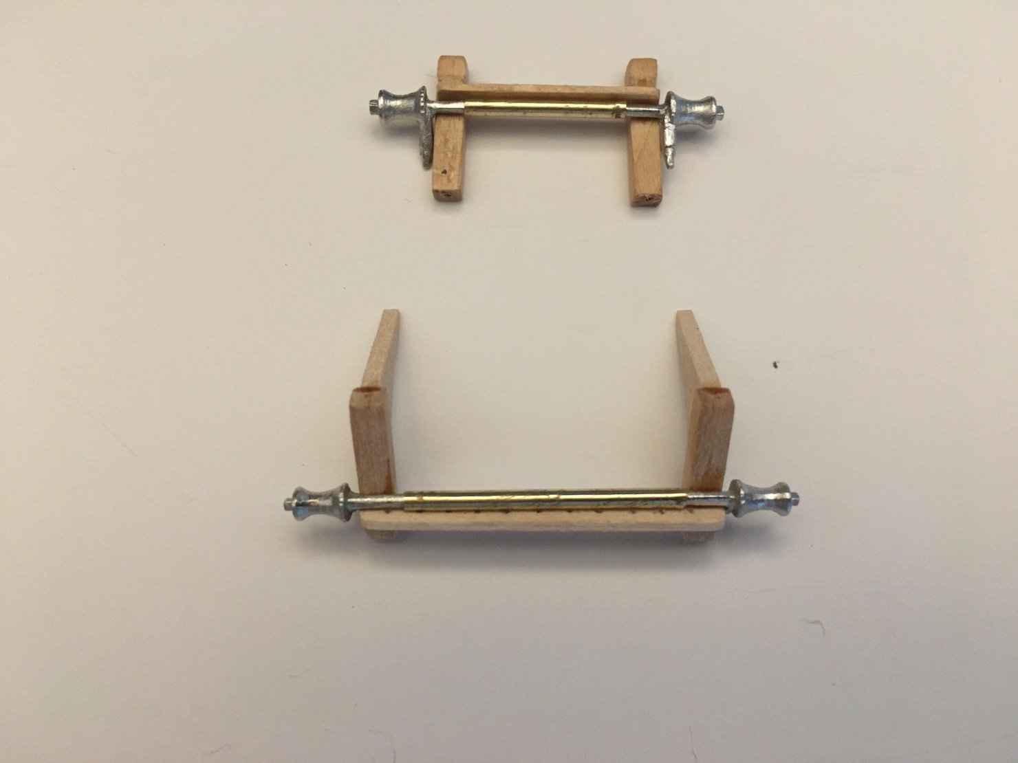
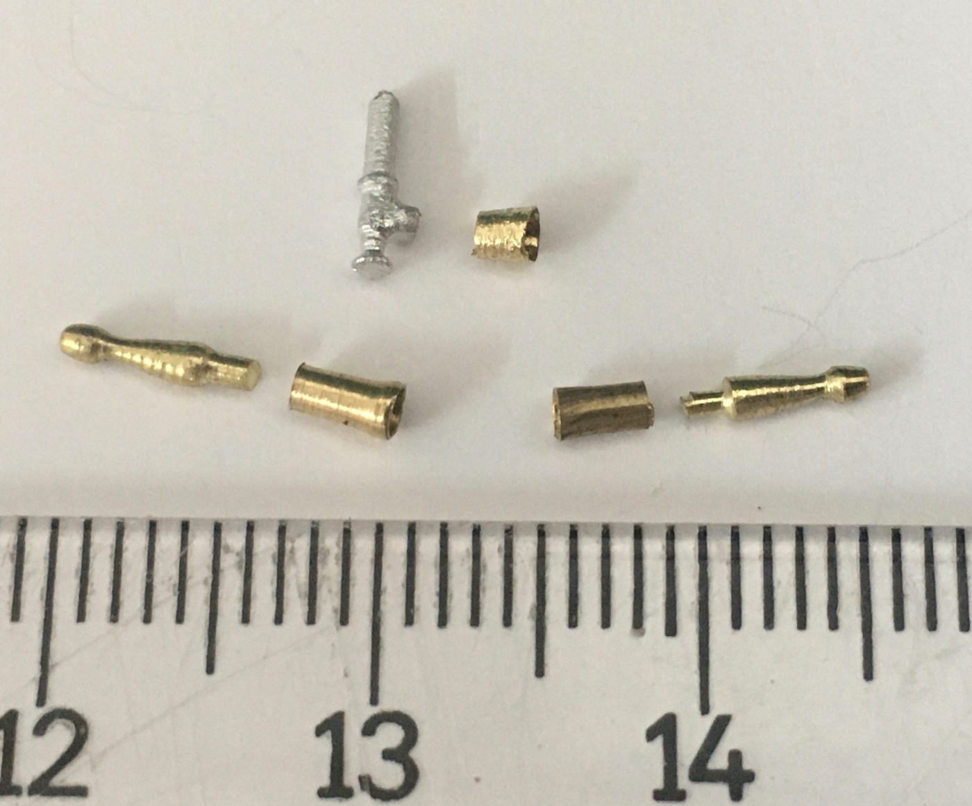
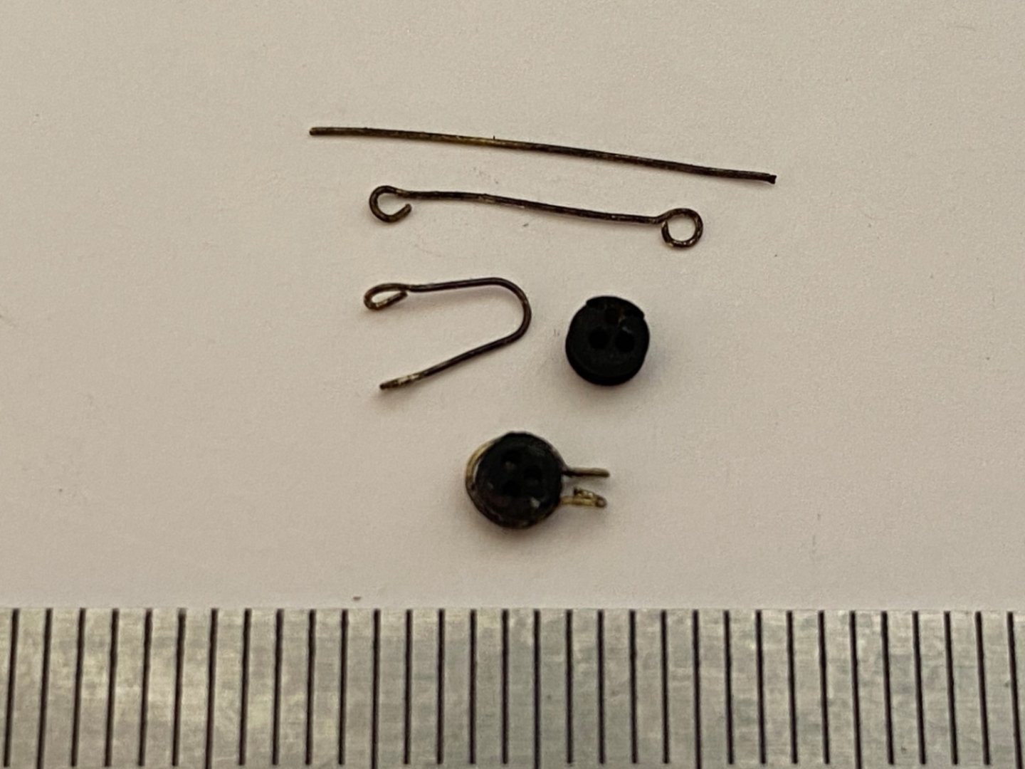
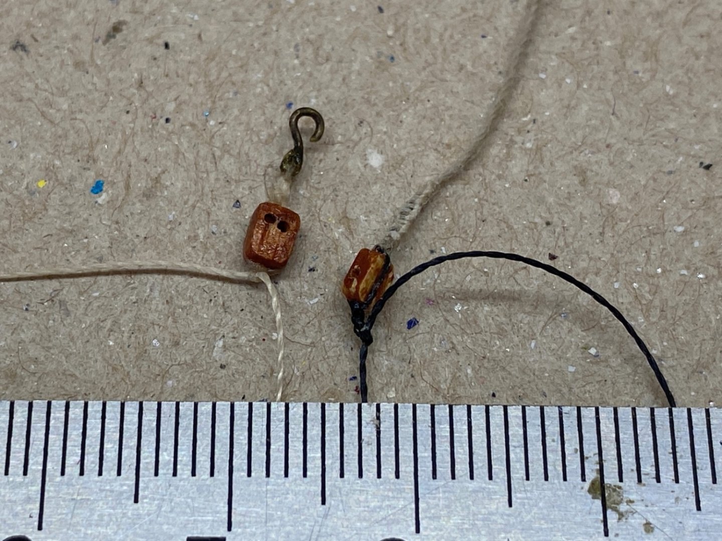
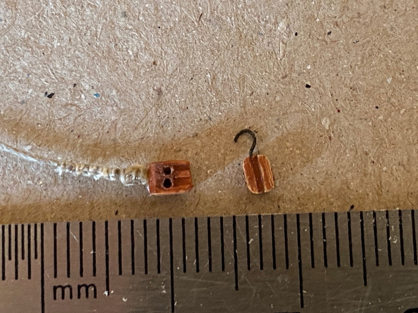
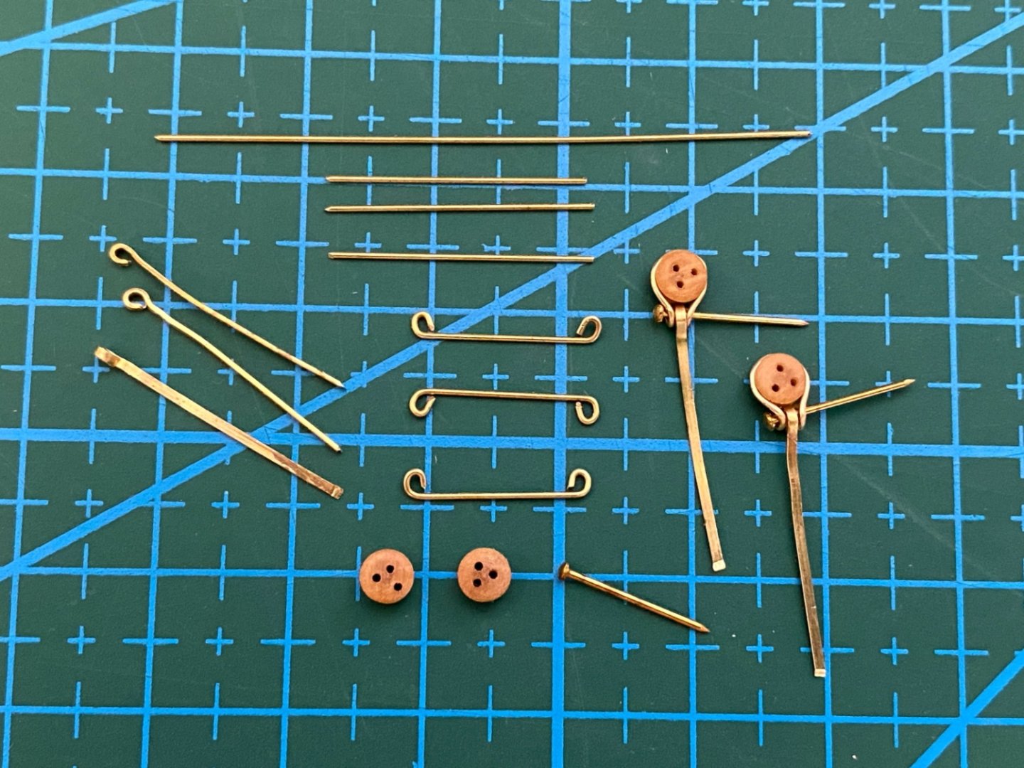
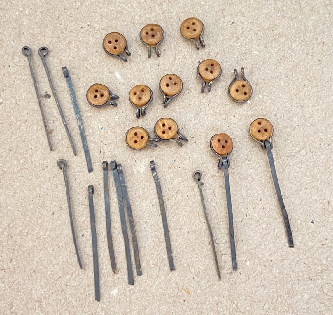
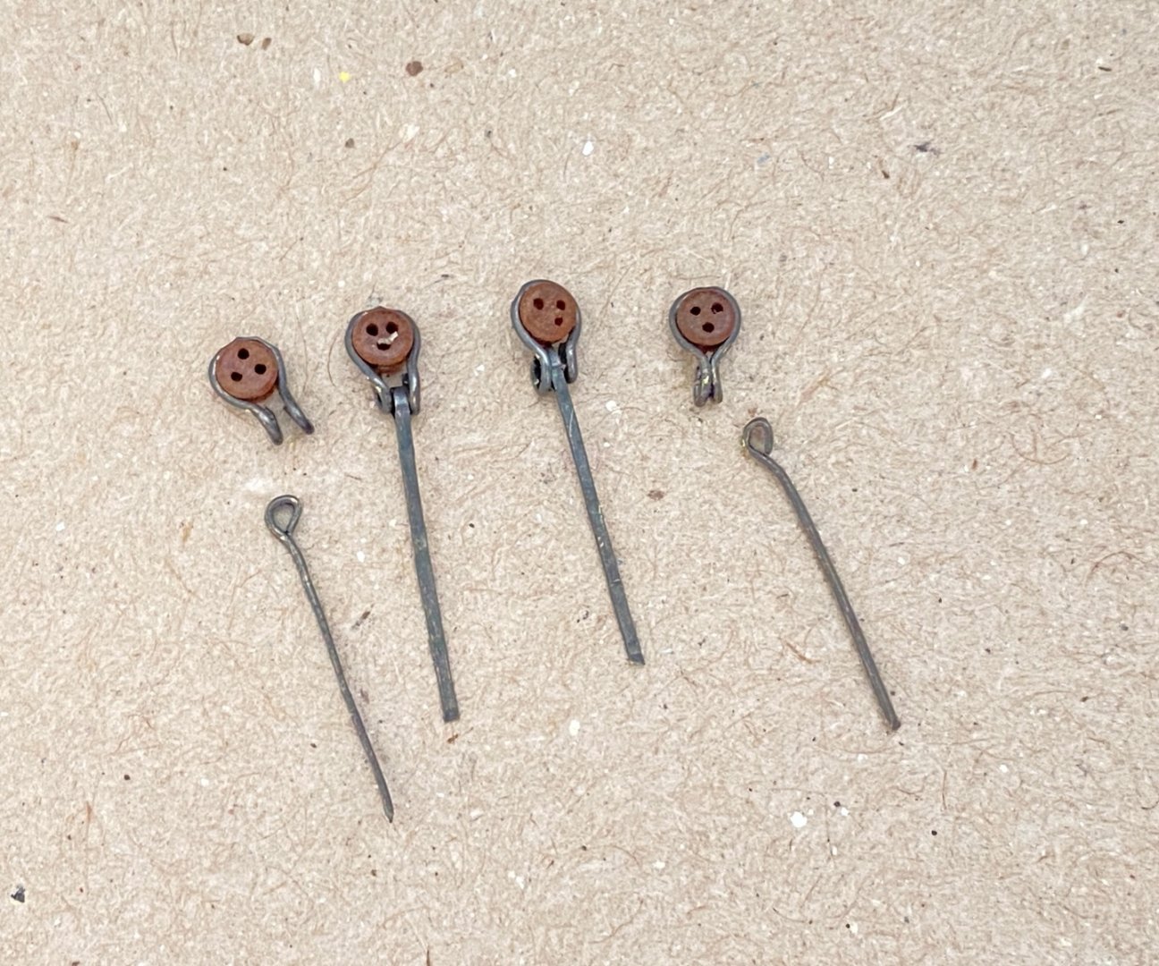
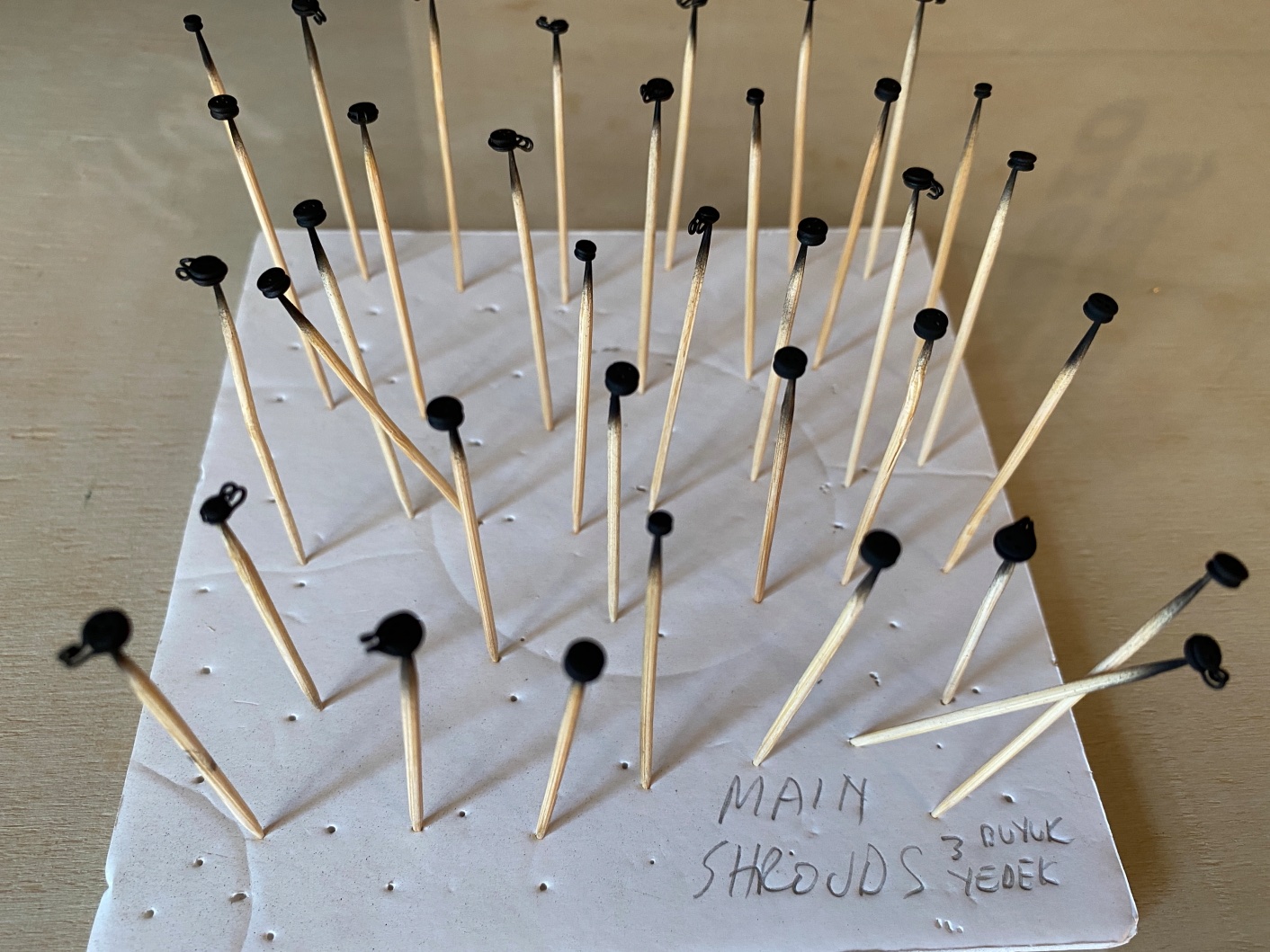
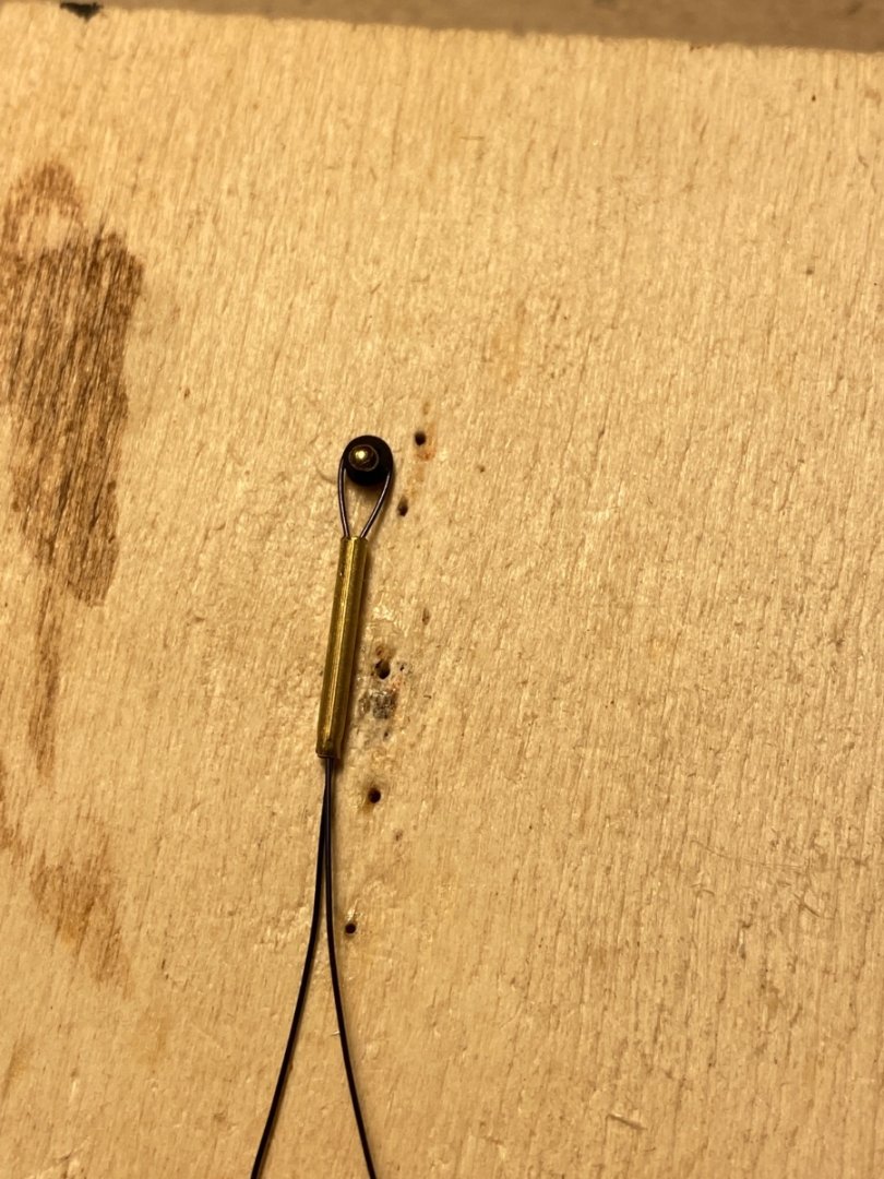
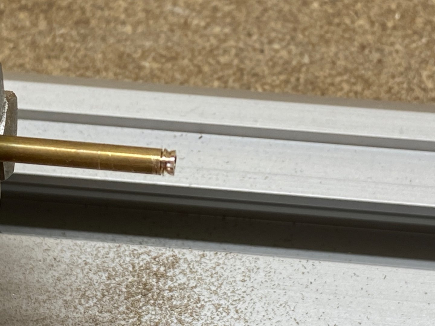
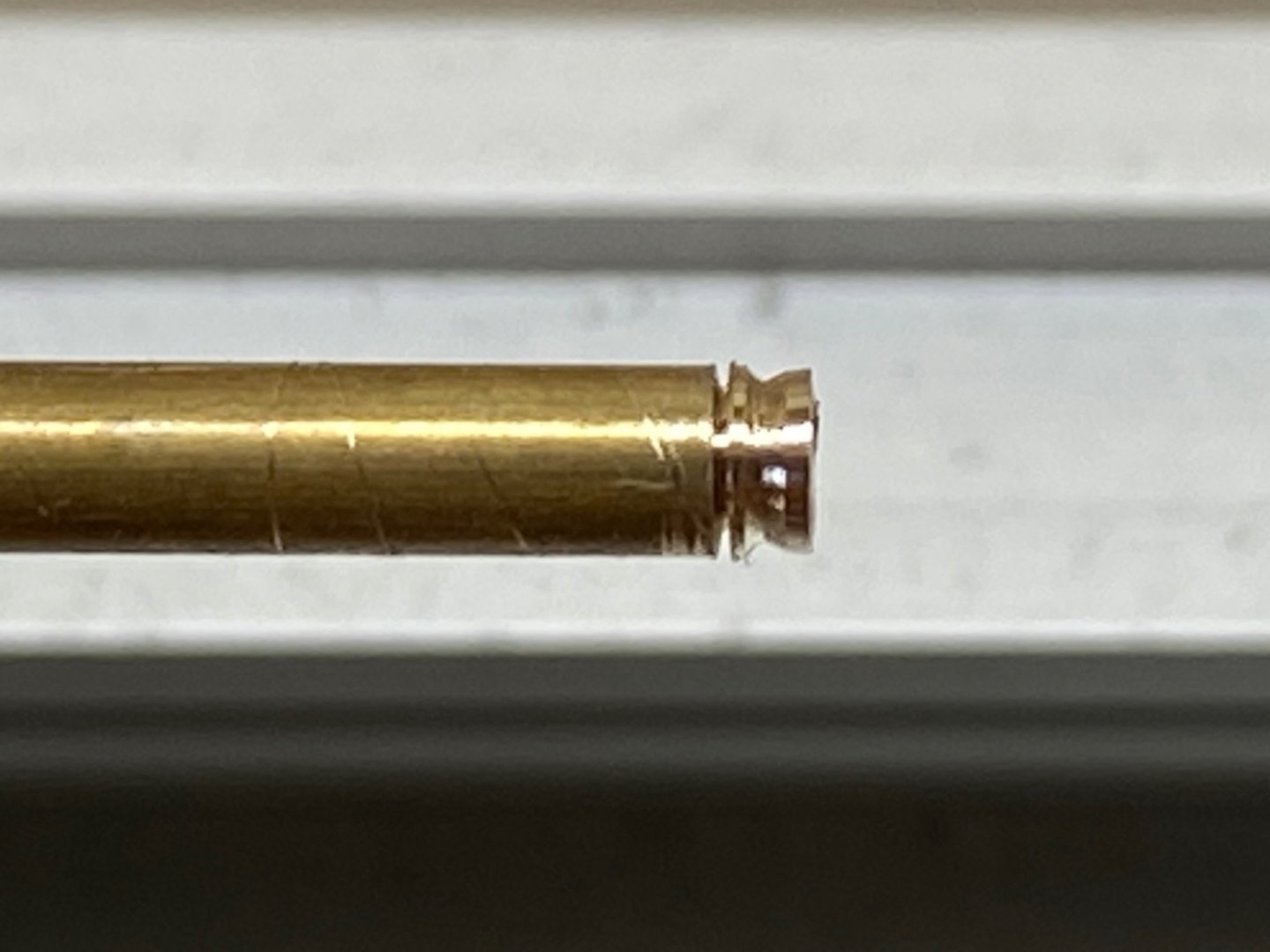
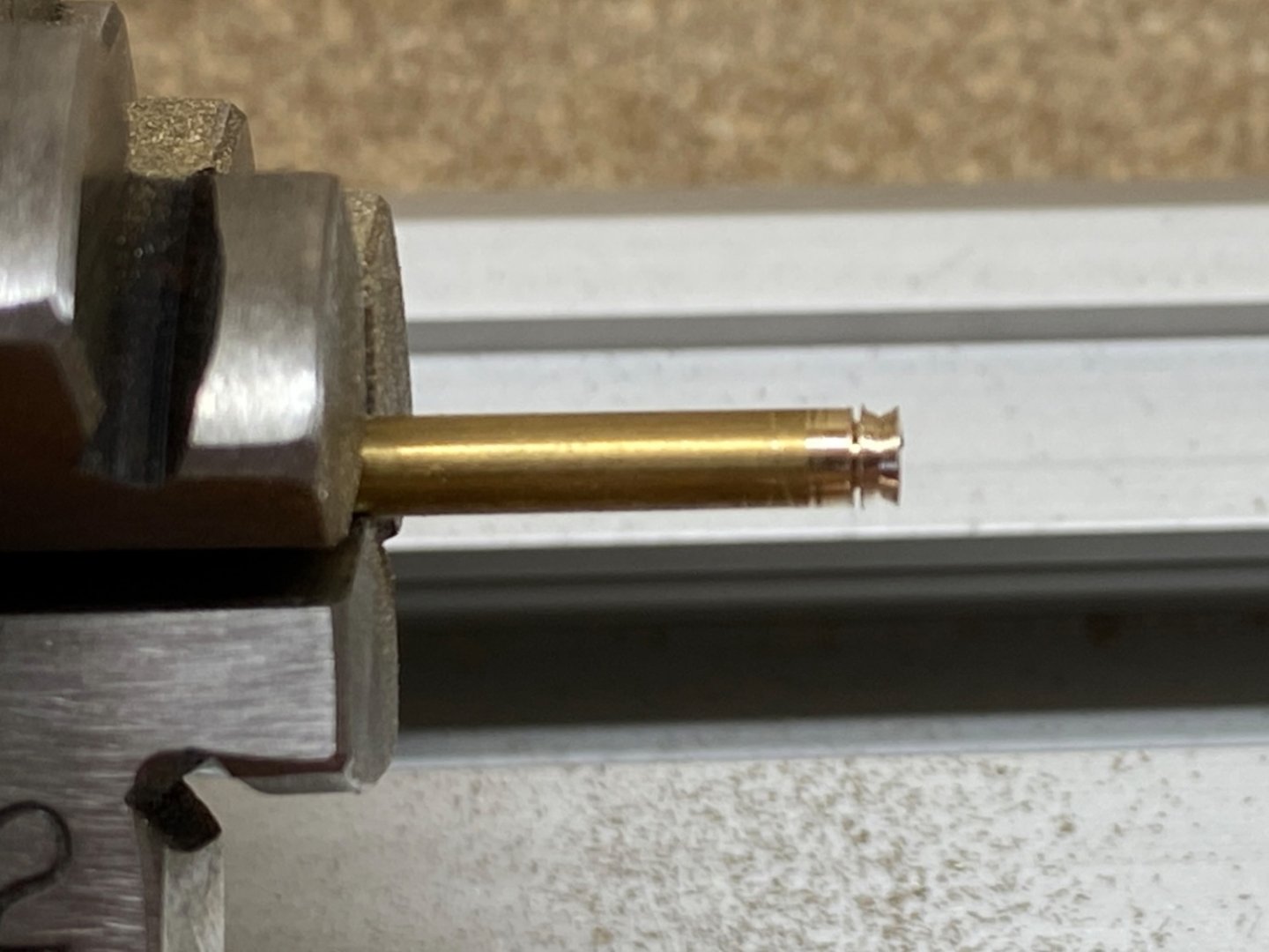
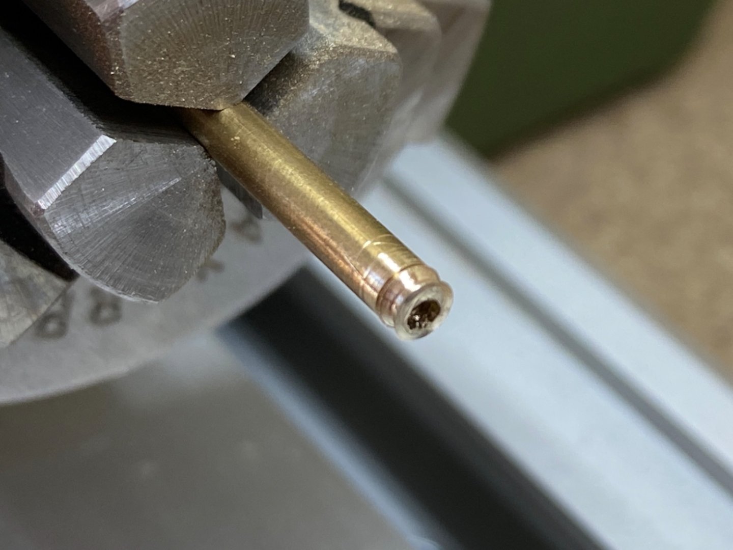
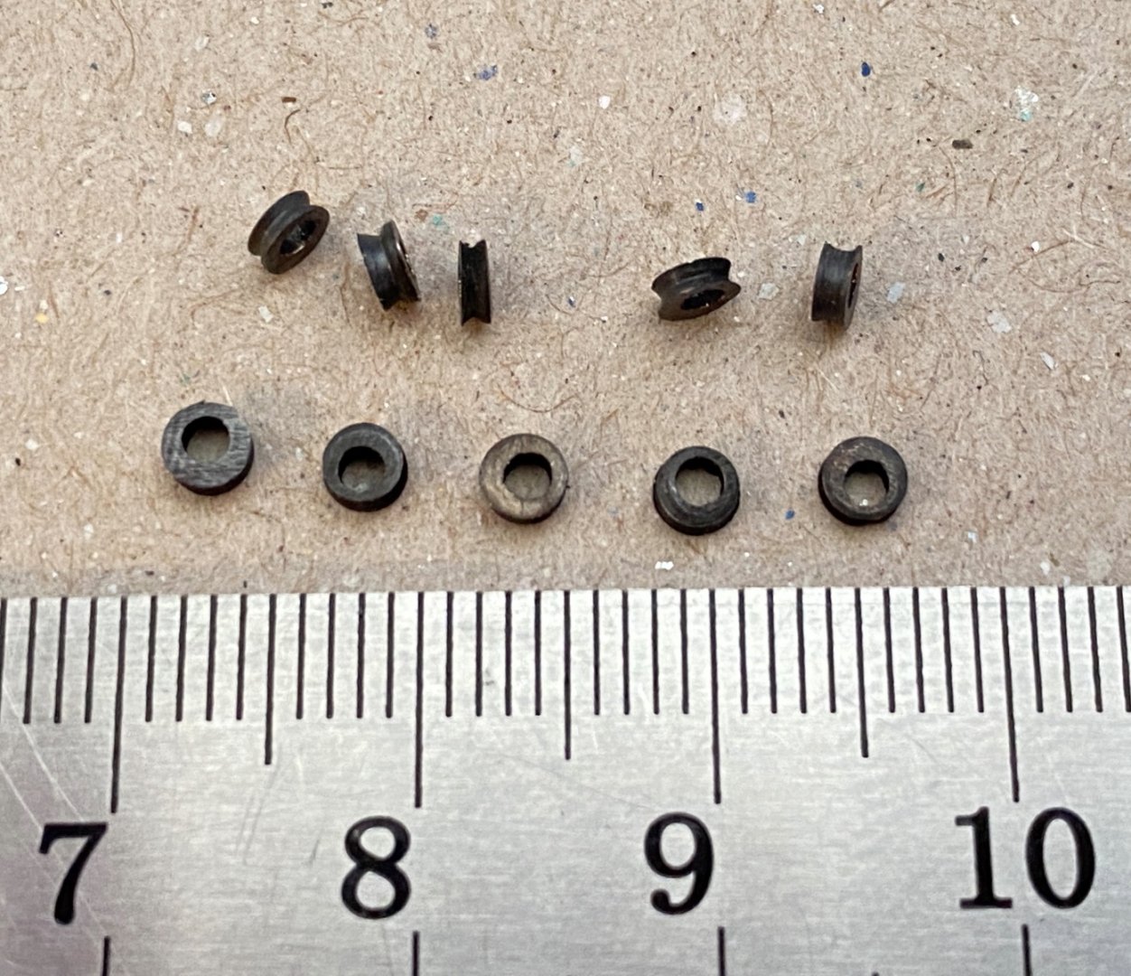
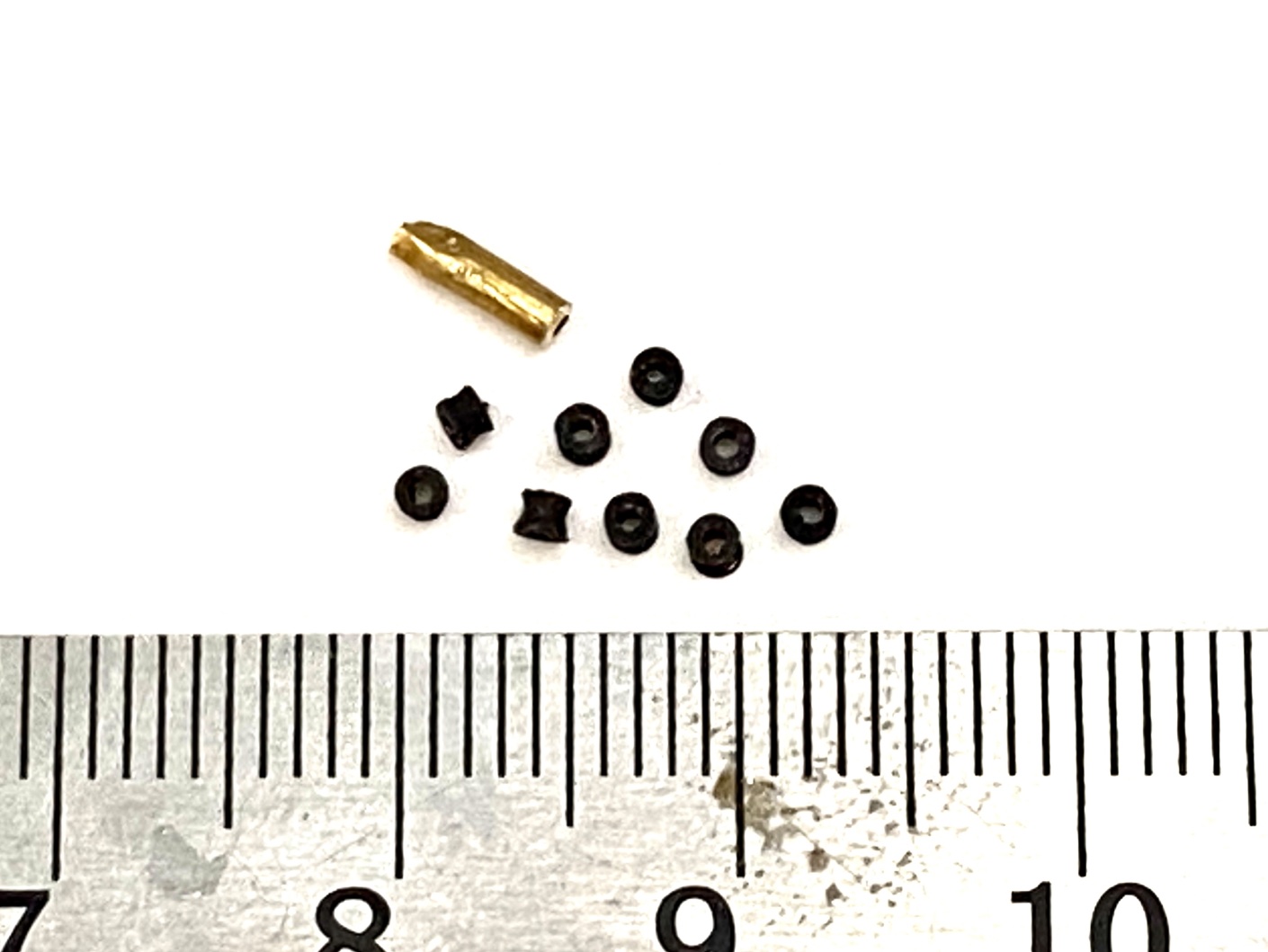
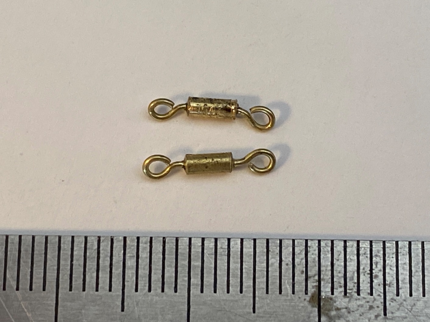
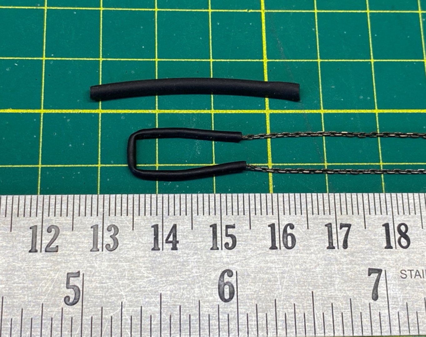
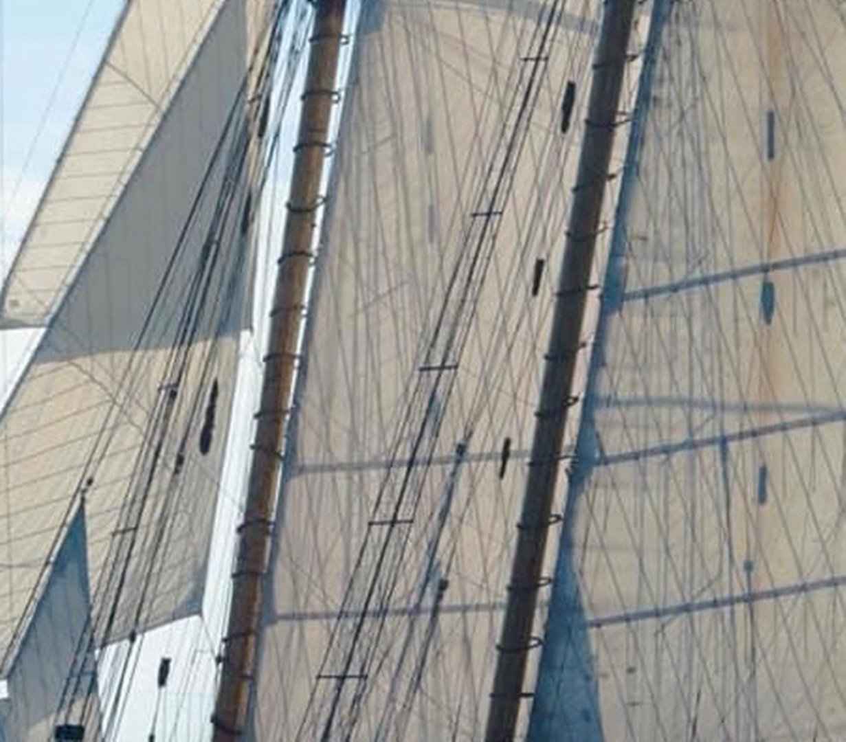
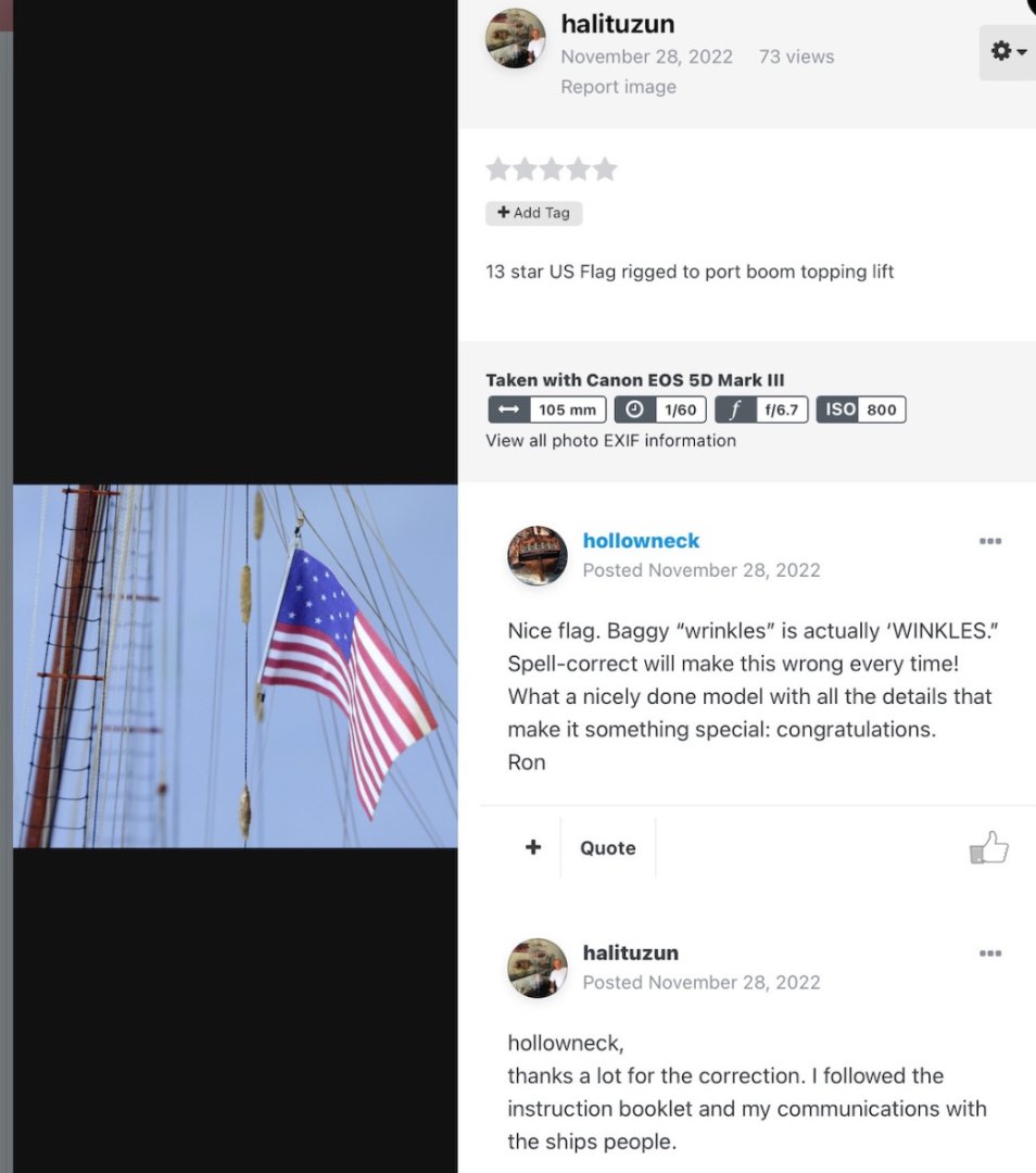
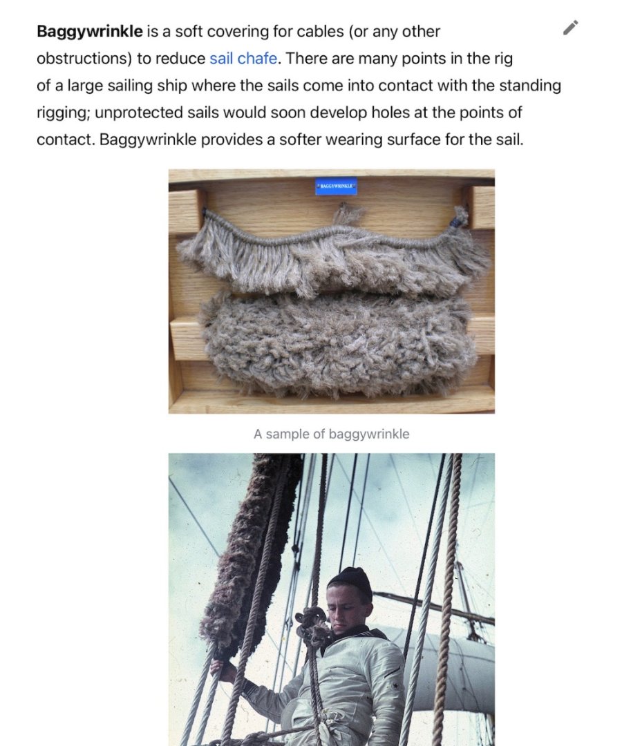
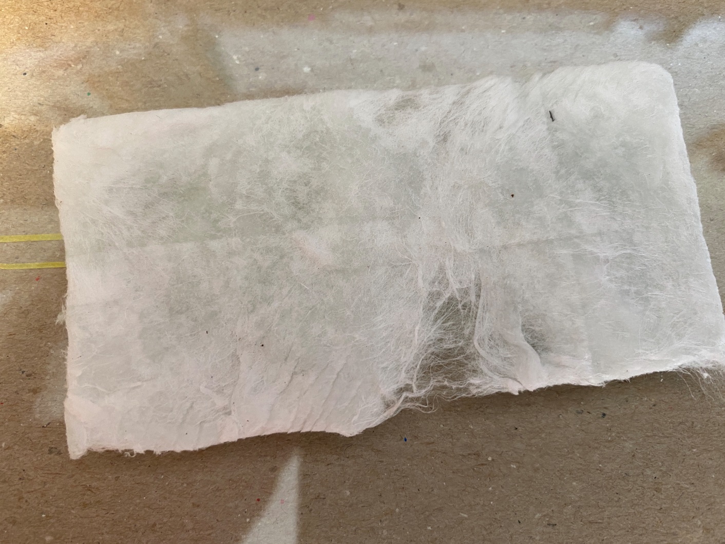
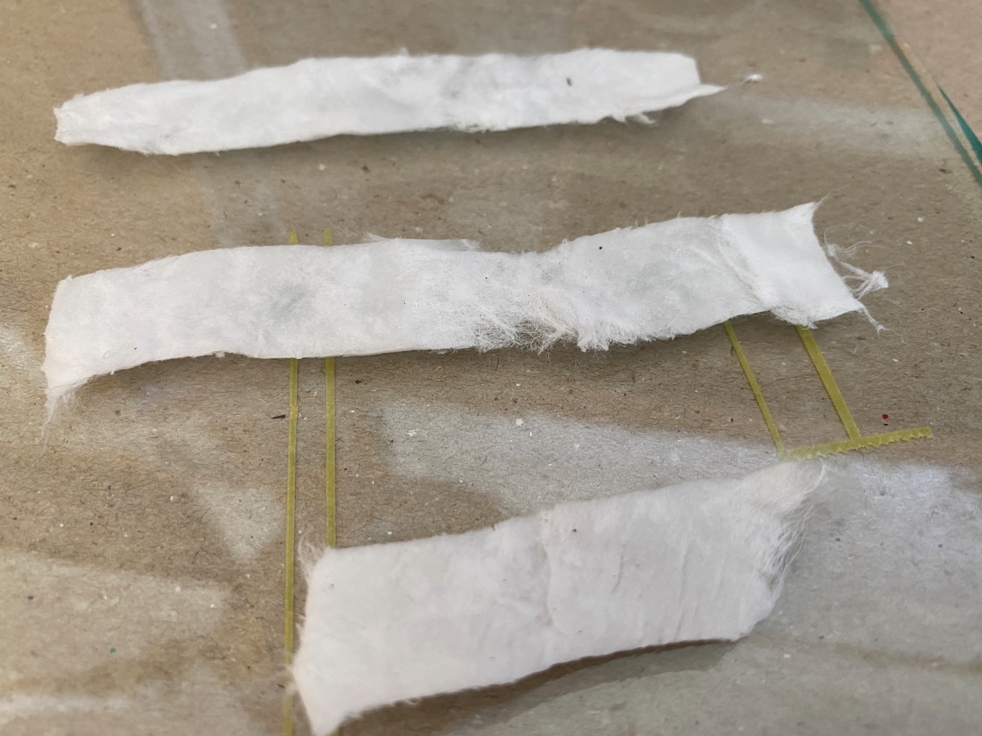
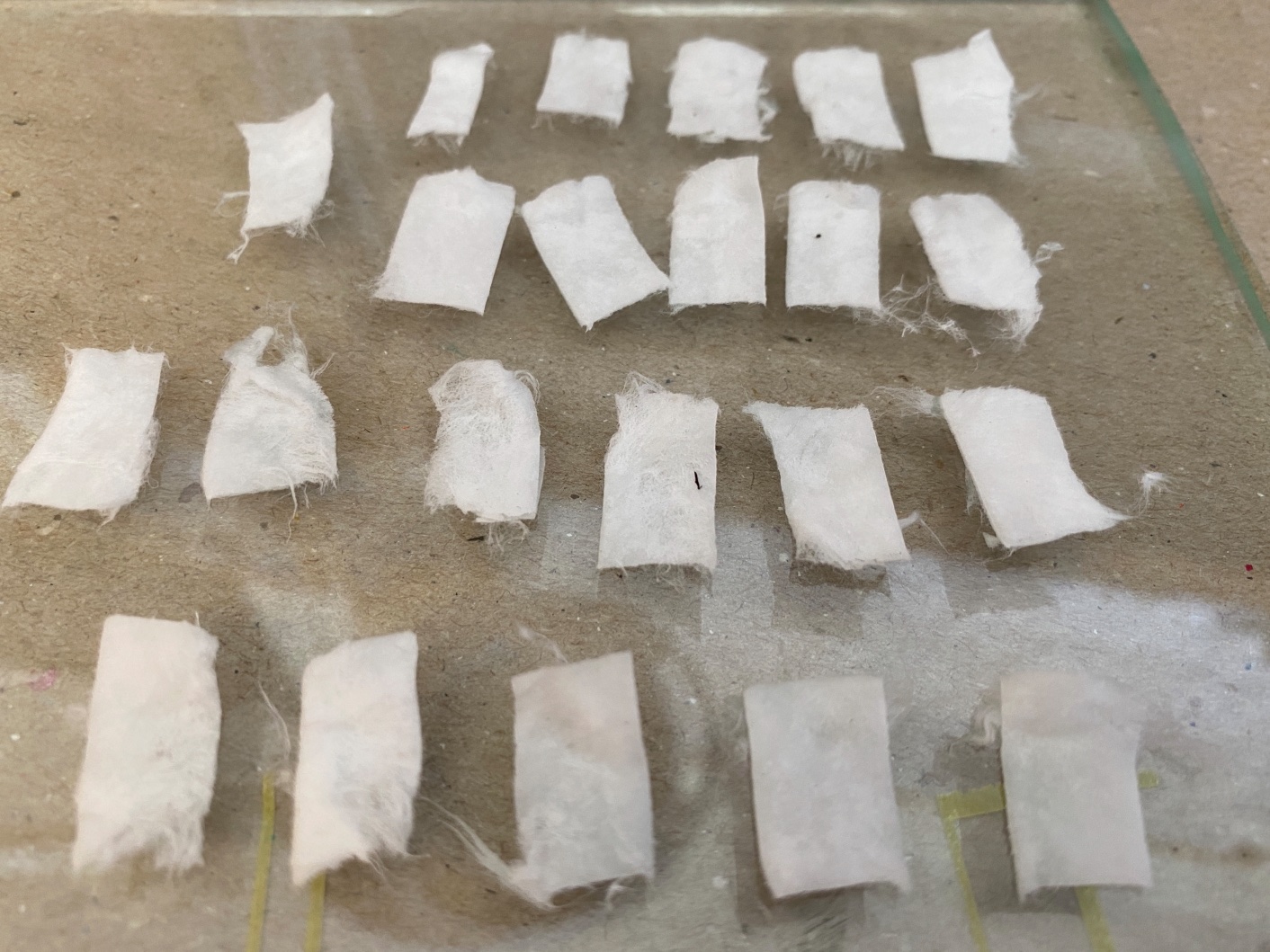
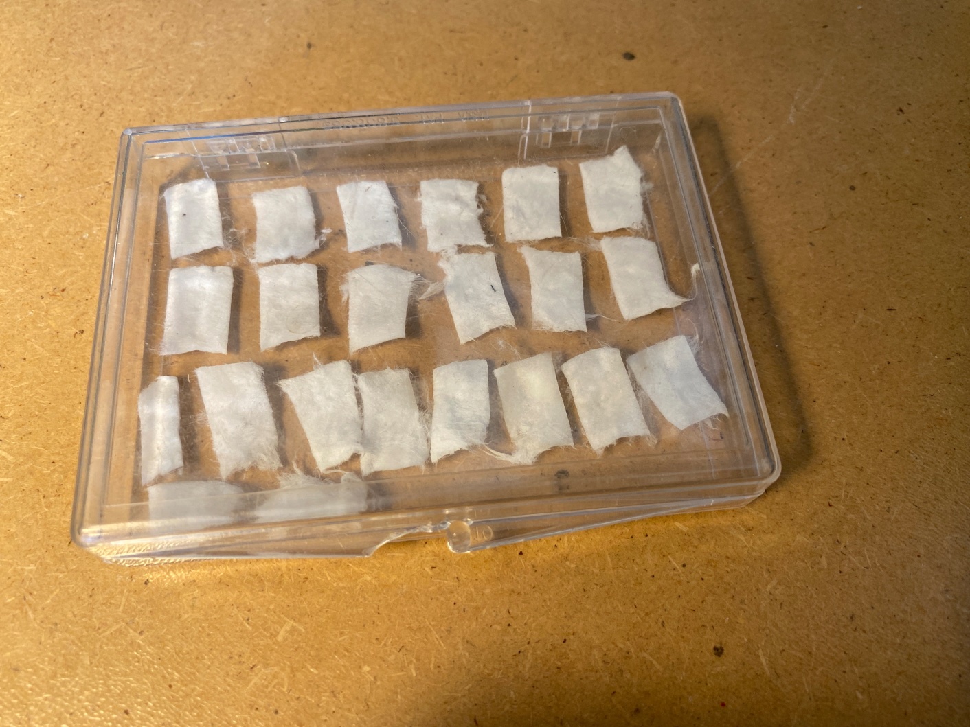
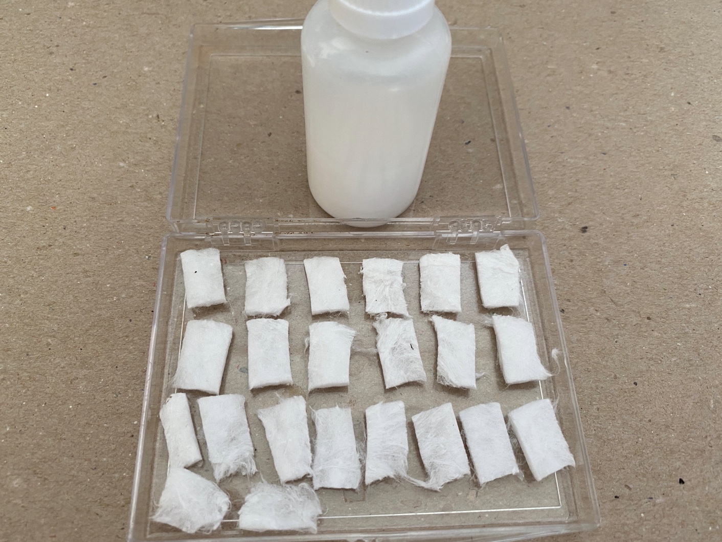
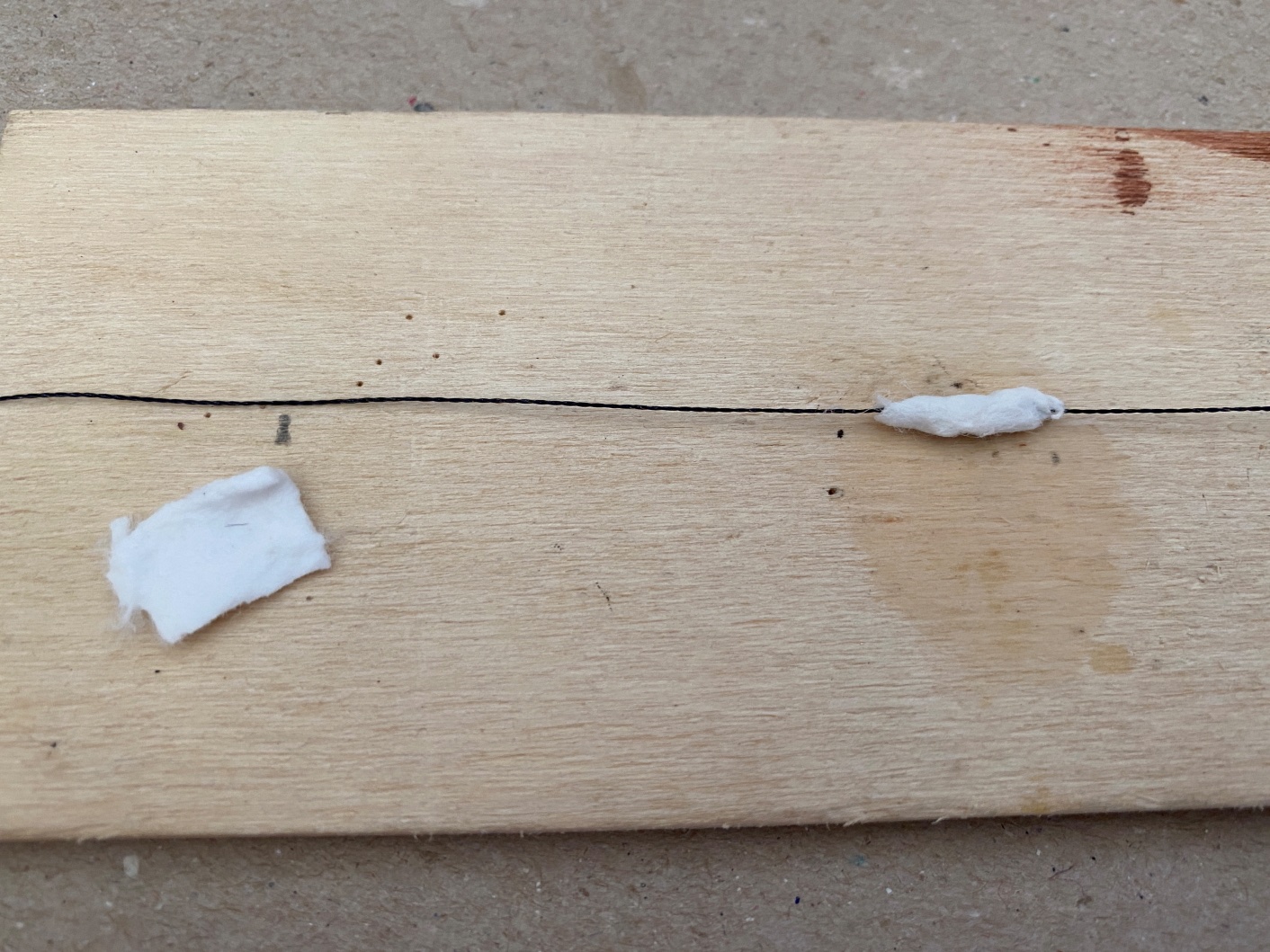
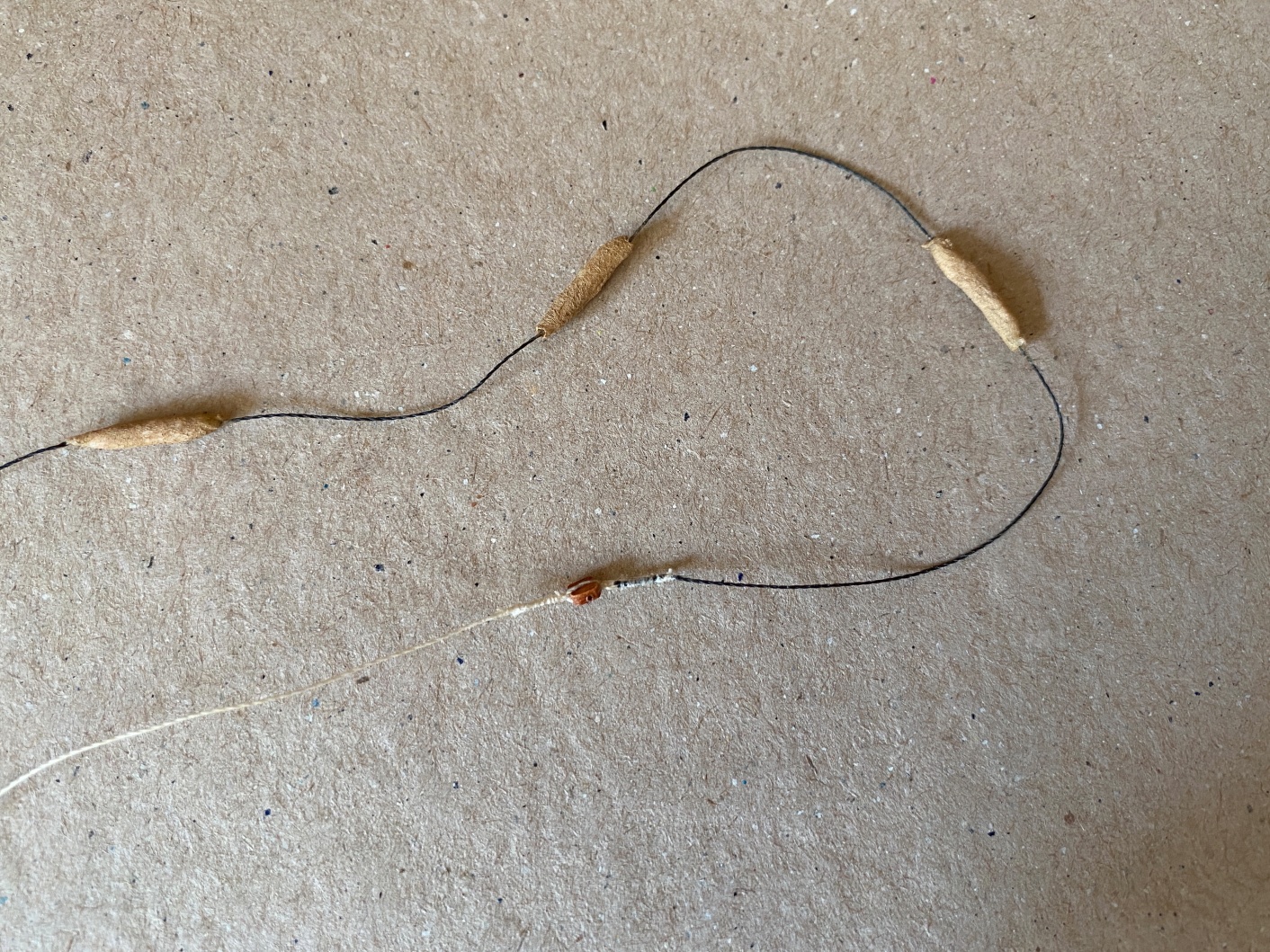
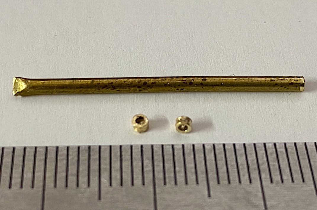
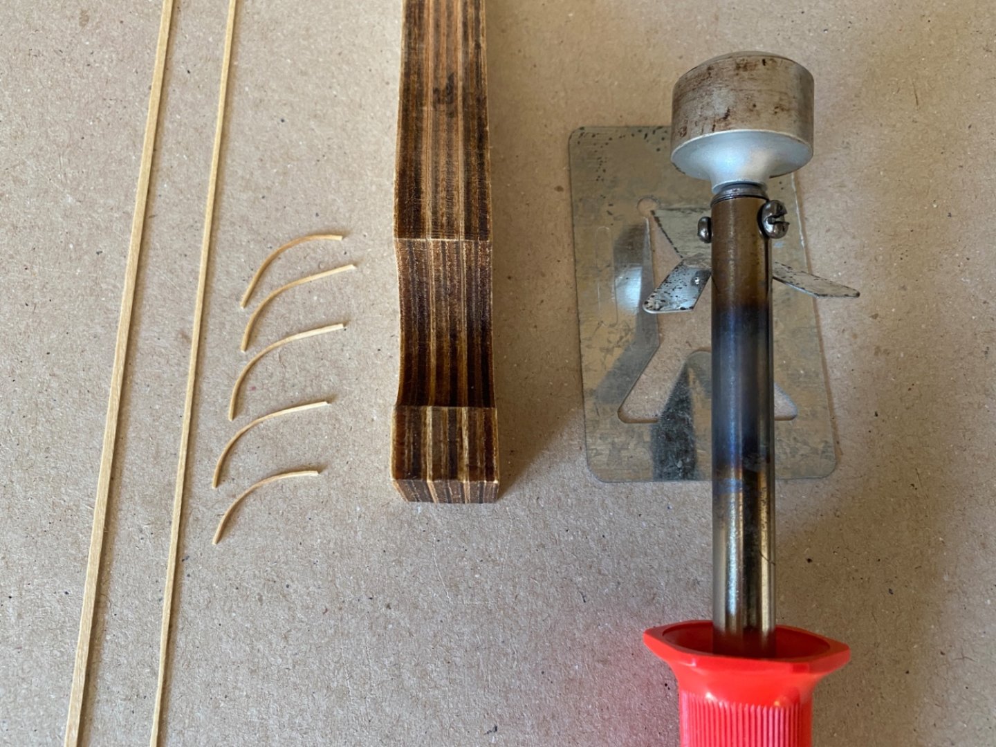
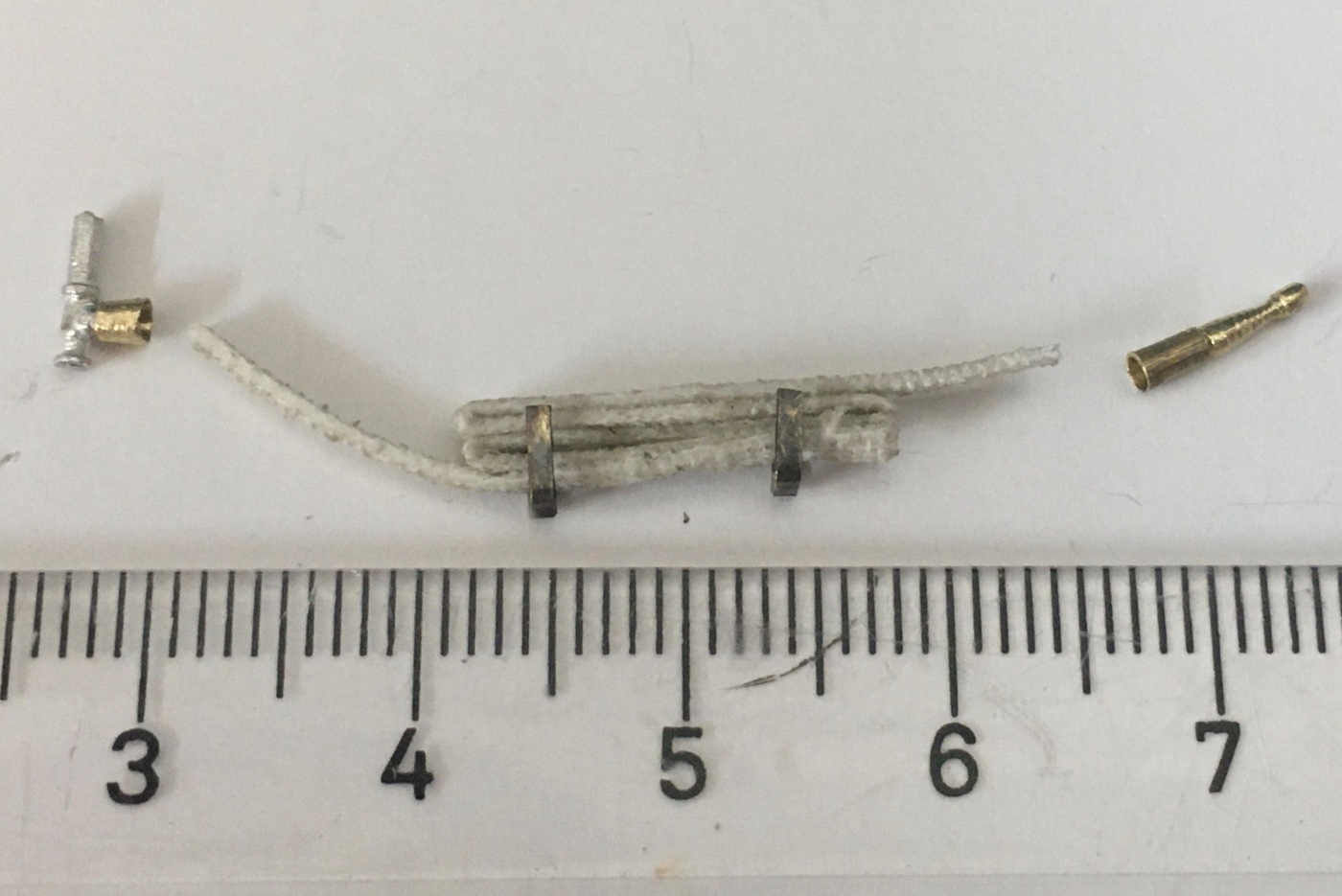
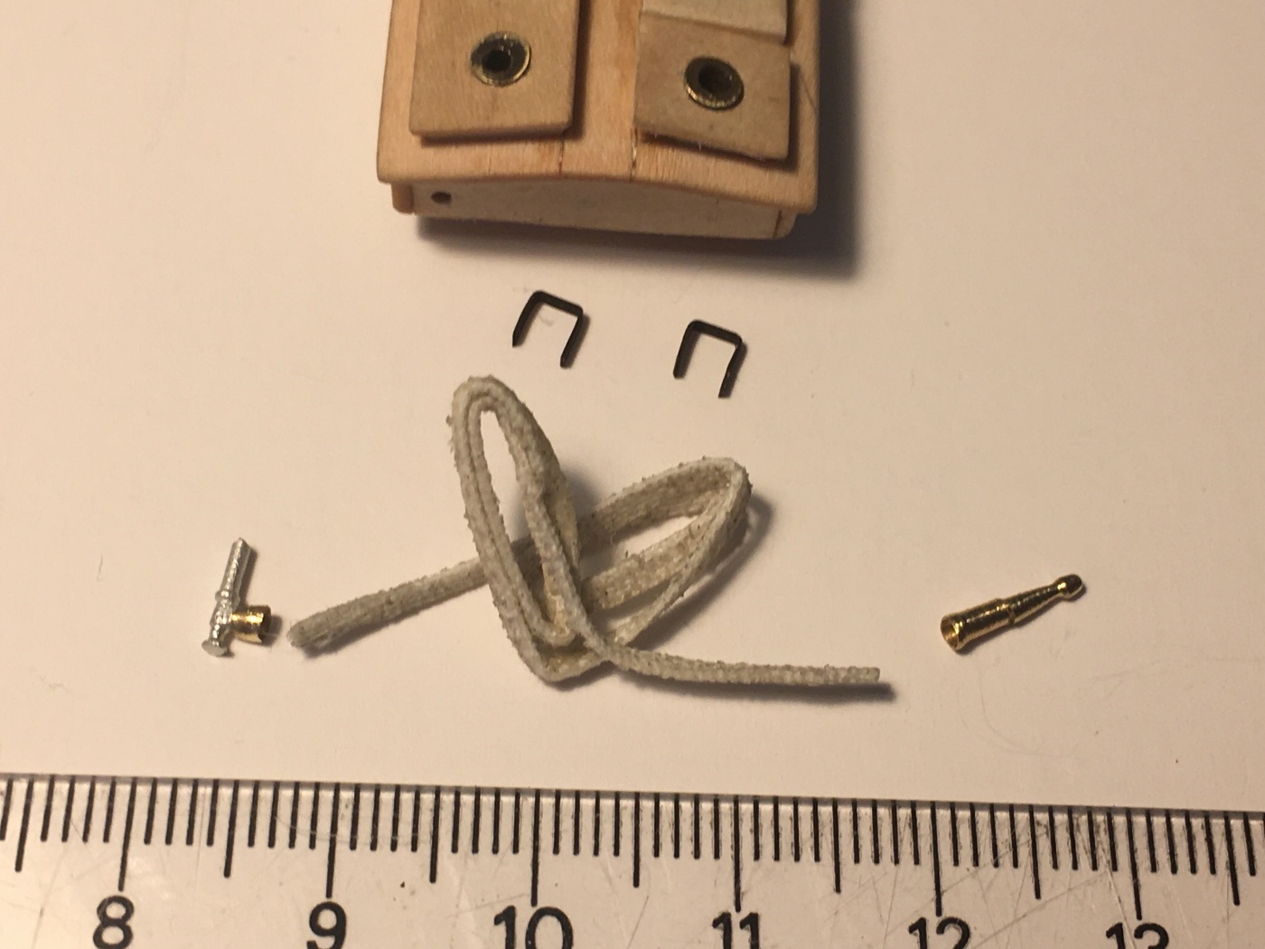
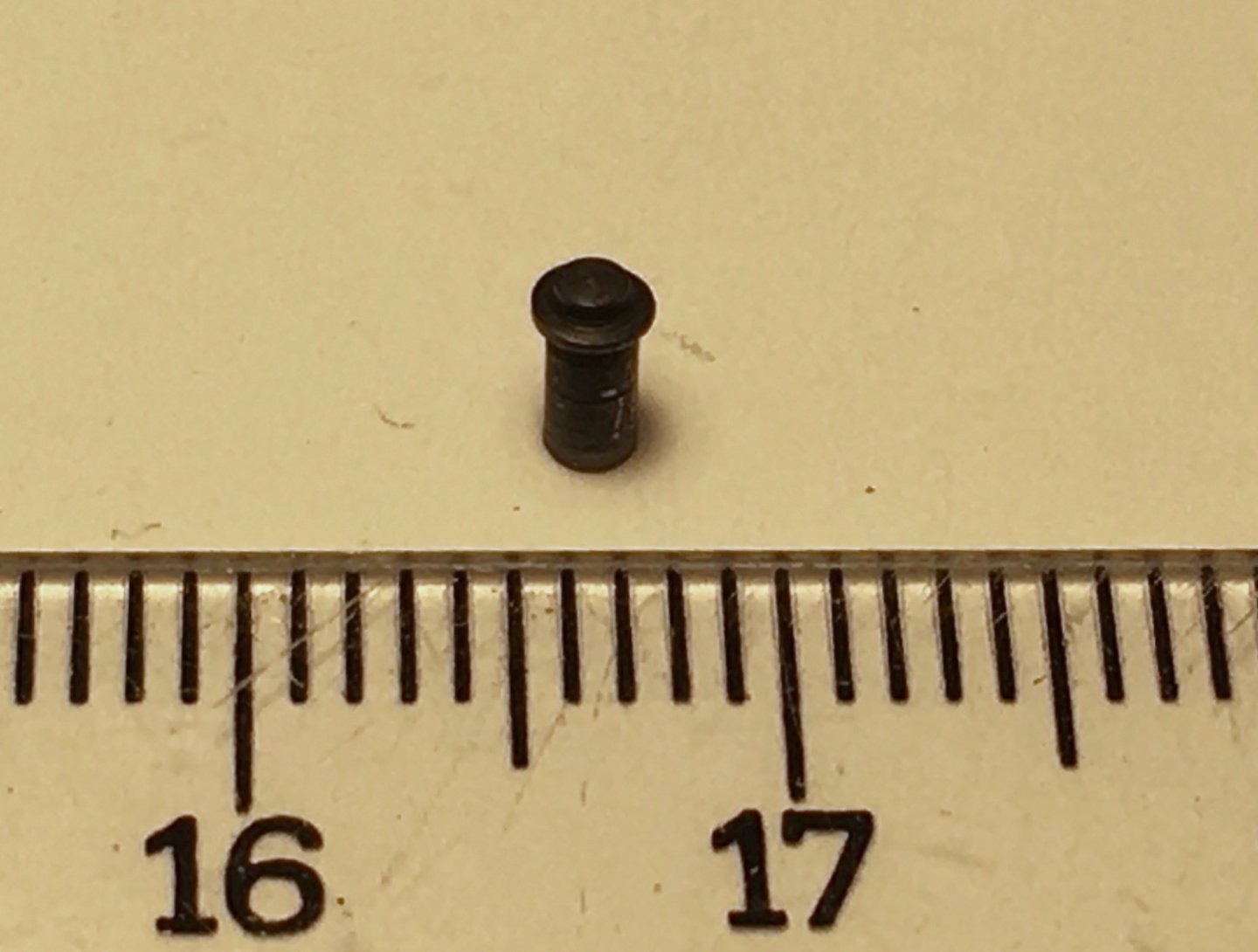
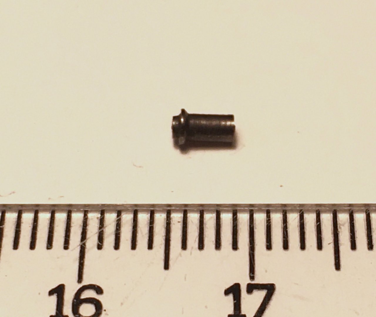
I continued with the preparation of the various details related to rigging such as stropping blocks, deadeyes, chain plates, thimbles, turnbuckles, lower yard sling and baggy wrinkles. I'll start with the blocks. In the photo below you can see the types of block stropping details. I prepared every block first by fixing it on a piece of rectangular plywood by a small nail (two for double or triple blocks) . The plywood then was fixed to the worktable by a clamp. The thread around the block was seized with the thinnest size sawing thread. At 1:64 scale I thought that it would be very hard if not impossible to construct metal shackles and thimbles of the blocks to eyebolts and used black thread instead to simulate metal. I regret not taking quality photos at these stages but you will see both the jig and finished block seizing photos in later posts. Here are some photos unfortunately with low quality. Deadeyes are used in shrouds, fore topmast shrouds and bowsprit rigging. Deadeyes for shrouds were prepared first. They are stropped with wire. At the same time chain plates were also prepared. Brass wire and sheets were used at this step. Suitable length wires were shaped to fit the grooves on the deadeyes. Deadeye connections with chain plates were designed to be moveable with a piece of metal rod securing it. Brass was blackened with Brass Black, which I was very happy with the results in the previous projects. Deadeyes were painted black At that time I also prepared the 4 small deadeyes of the backstays . I decided to use 0.2 mm black wire as the backstay line at that time. 0.2 mm wire looped around the deadeye and tightened with the aid of a brass tubing. Then they were seized by thinnest black thread. However in the later rigging steps I prepared the backstays again but with black thread. There are several metal thimbles used in rigging as you see in the photos below. 12 in futtock shrouds, 6 in topsail yard jackstay, one in fore topgallant stay and 5 for main and fore topmast flags and signal flags. I prepared the metal thimbles from 3 mm diameter brass rod turned in Proxxon DB 250 and drilled by a 1.5 mm HSS drill bit. Blackened by Brass Black. However when the time came to install them it was not hard that they were large and out of scale. Then I used a 1.5 mm outer diameter with a thick wall brass tubing and prepared the thimbles again using DB 250. Photo (sorry for the quality) after blackening of them. There are two turnbuckles used in the standing rigging of the main topgallant stay (red arrow) and main topmast stay (blue arrow). I prepared them from brass tubing and eyebolts. Later I modified them. By filing two sides of the brass tube two openings were made and the tips of the eyebolts can be seen. Lower yard sling was prepared by using the smallest diameter (1.5 mm) heat shrinking tubing and smallest sized chain I found. Of course some trials were made and the final prepared one is the second photo. There are baggy wrinkles on the running backstays to prevent sail chafing. A modeller friend corrected the term as 'baggy winkles' in his comment to a photo in my album in finished photos section. However I checked with wikipedia and confirmed the term to be ' baggy wrinkles' . The term is also confirmed by my correspond with the real ship's crew. Here is how I prepared them. I wetted a piece of cotton with water and pressed it to a rectangular shape. Then cut sheets . Smaller rectangular pieces were cut from those sheets. The small sheets were wetted again with water and put aside to dry. After they dried and sized to final shape they were wetted by diluted white wood glue. Then the wetted piece is wrapped around the black starting from one end. The piece is then rolled fore and back a couple times over the black line with using the thumb and index finger. The iines were hanged to dry.After they were dried they were dry painted with a cut brush using Tamiya XF-78 Wooden Deck Tan color. The whole process was easy. I even prepared the missed one on the jib stay after the line was rigged to the model. Here is another example for the out of scale parts of the kit. There are eyebolts with rings at inboard bulwarks of the gunports. New size rings were made instead of the large ones (bottom of the photo)


- 114 replies
-
- 5
-
-
-
- Pride of Baltimore II
- Model Shipways
- (and 1 more)
-
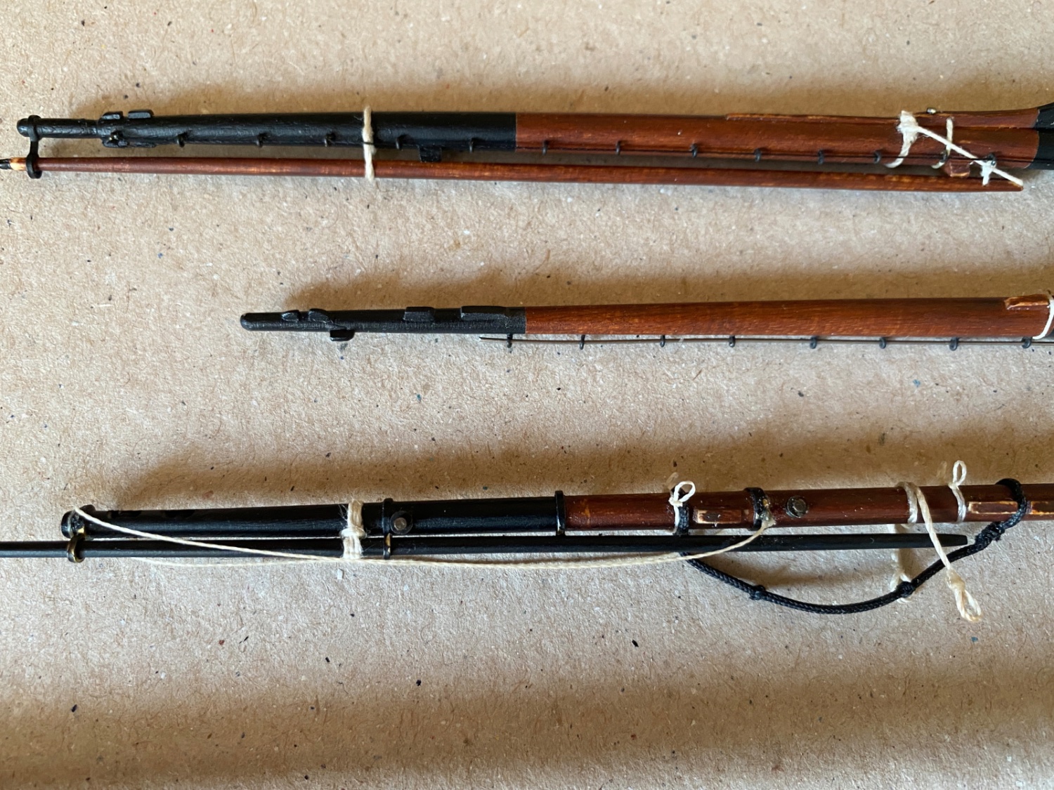
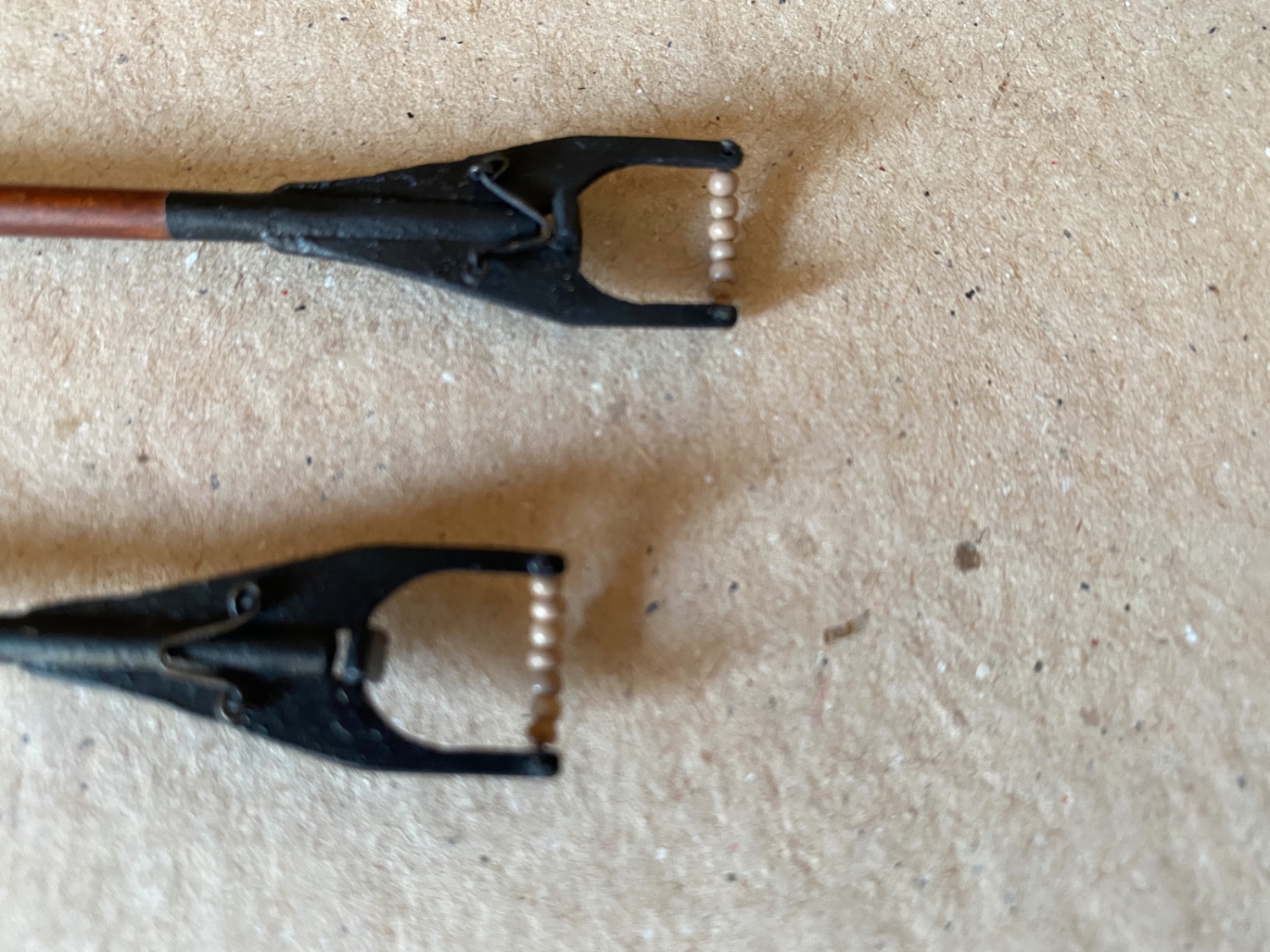
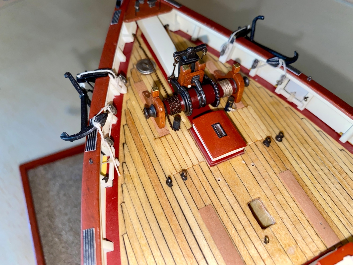
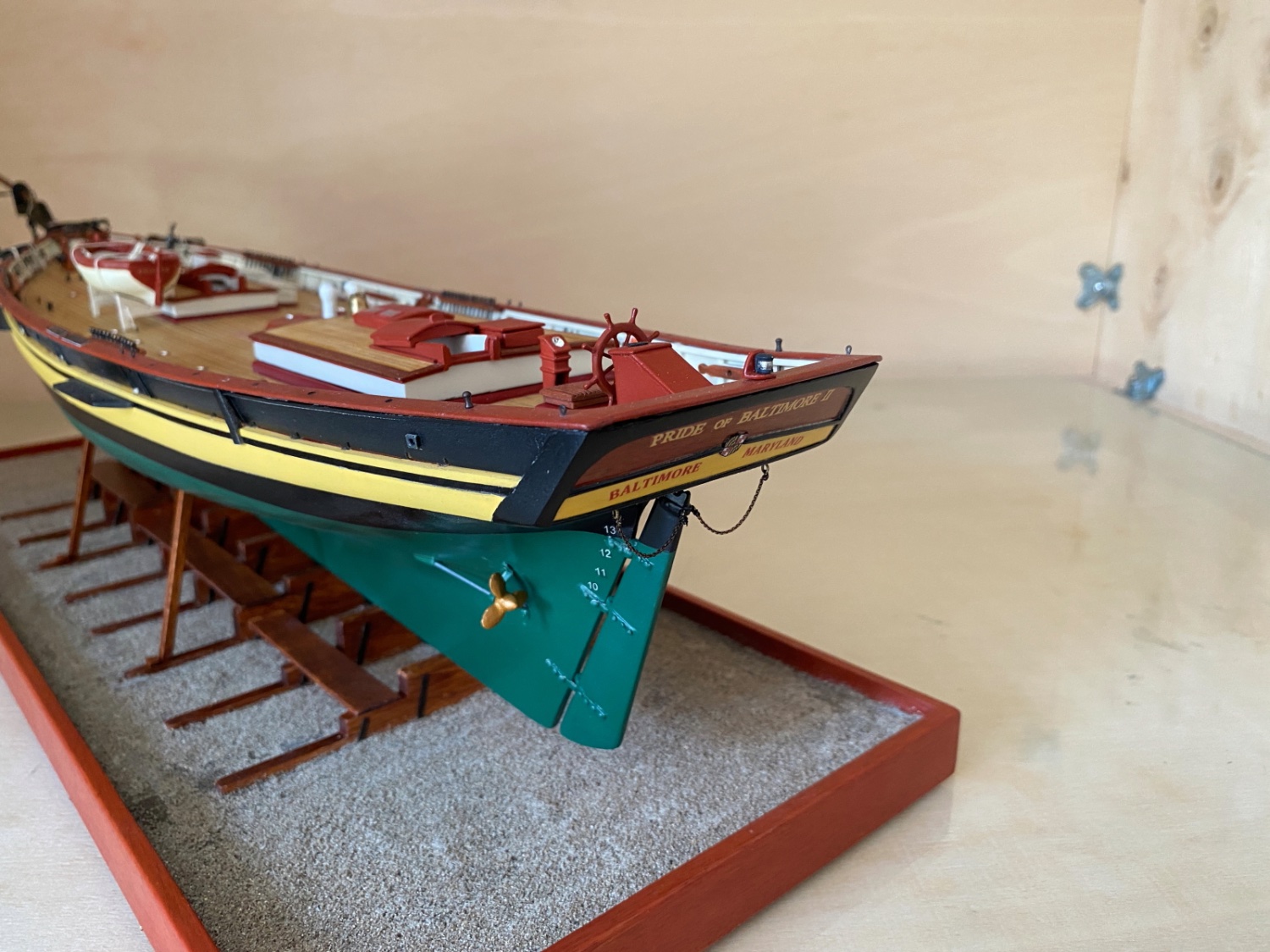
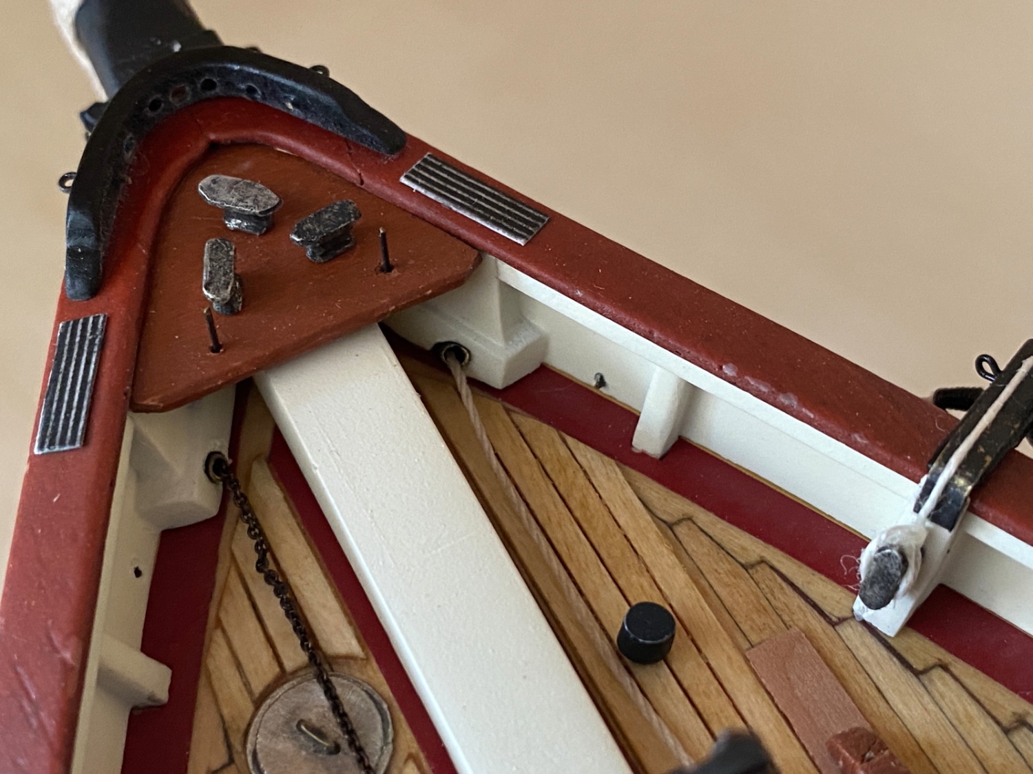
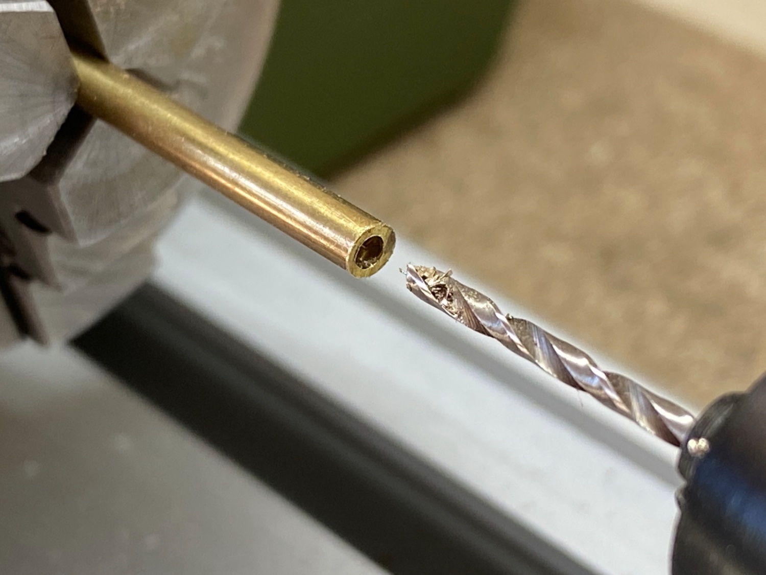
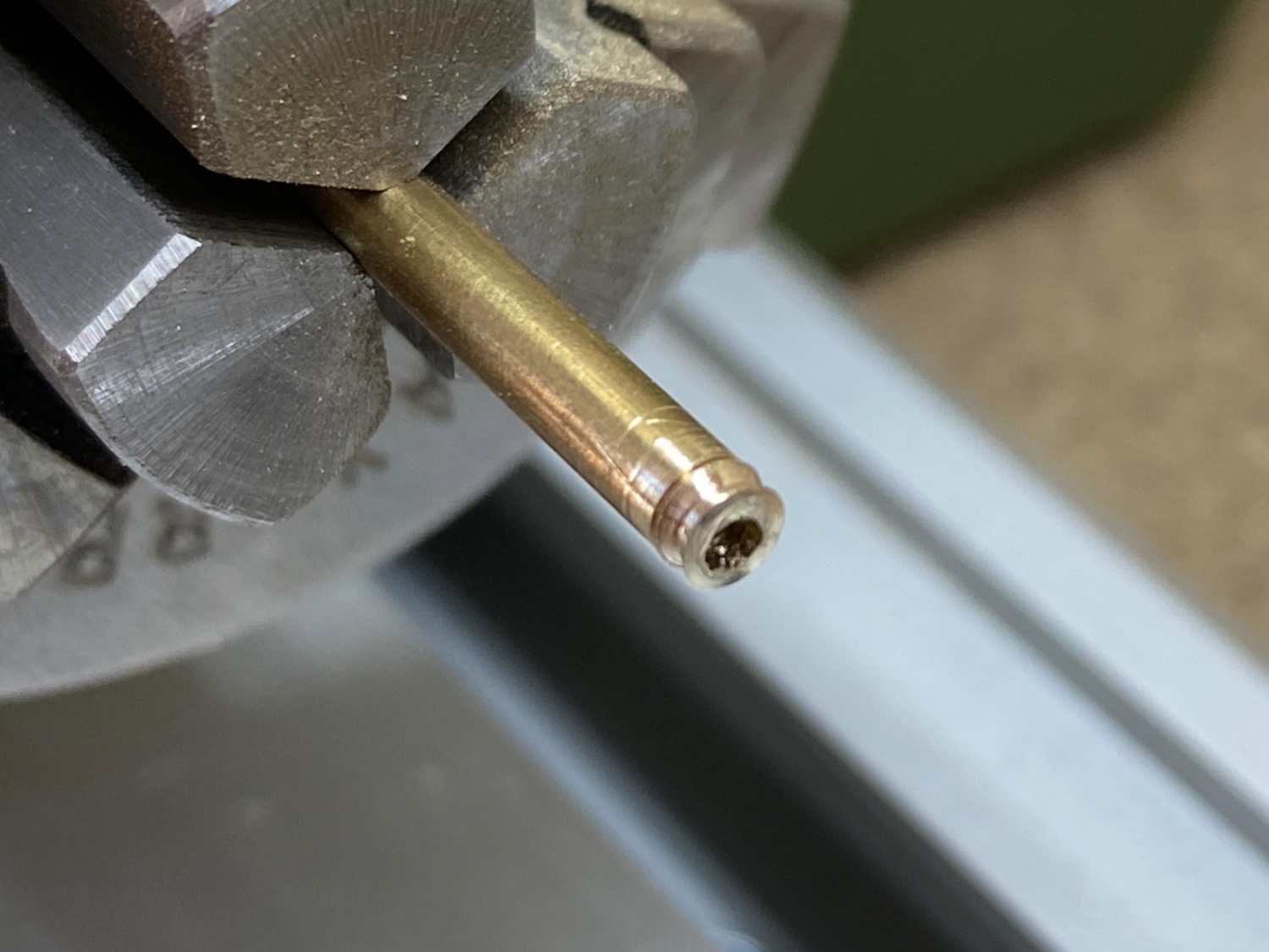
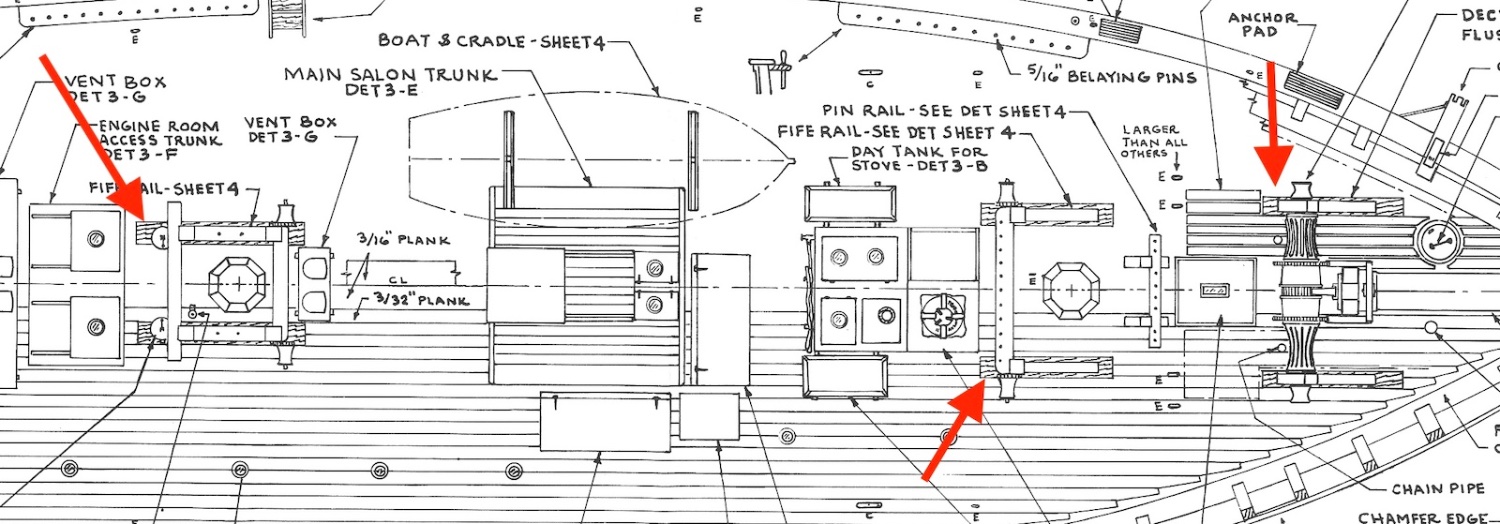
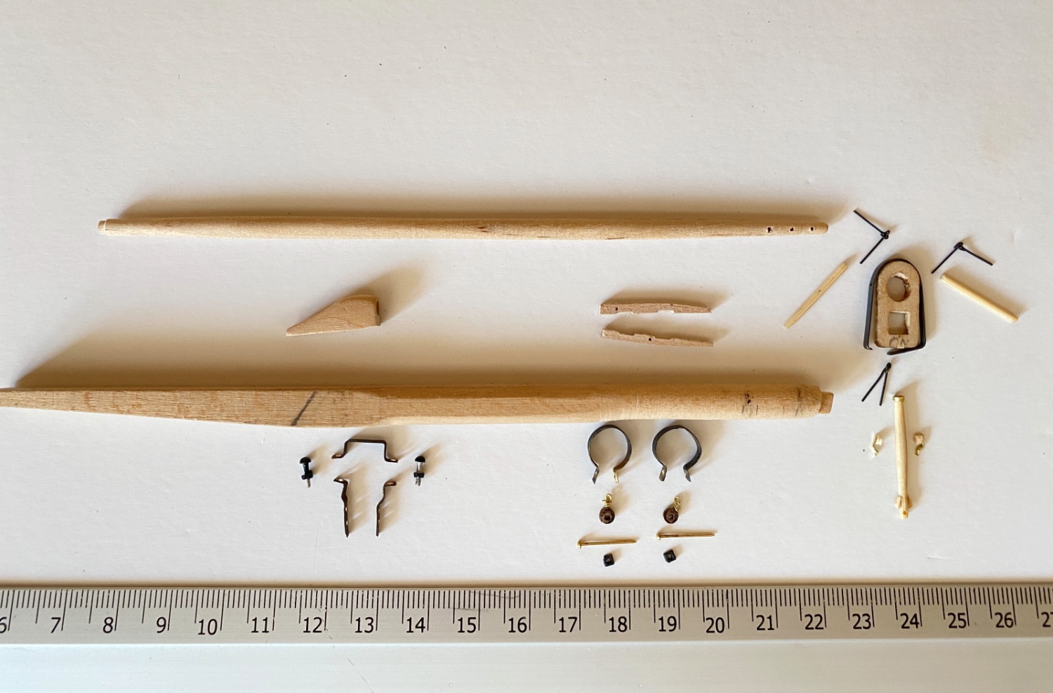
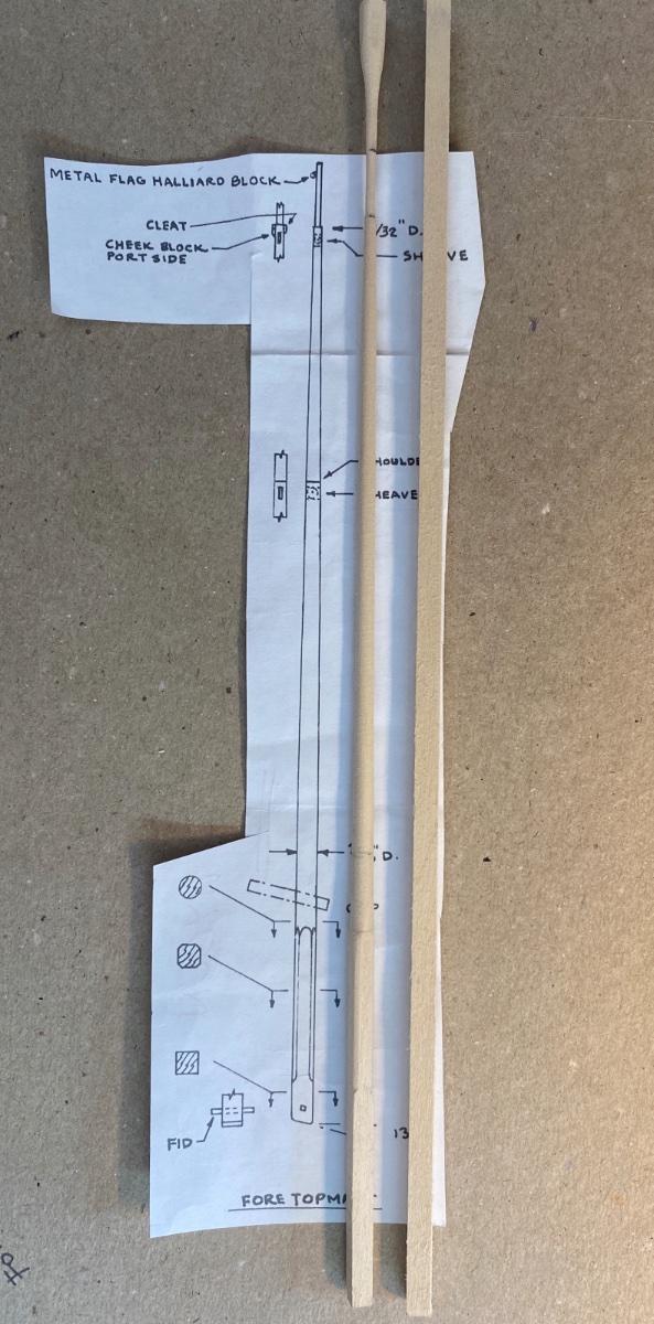
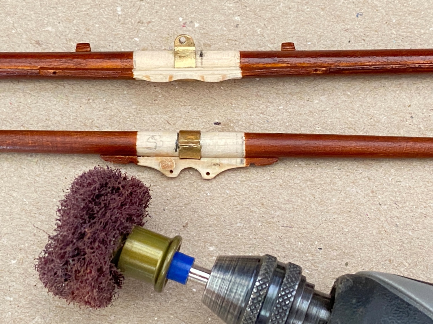
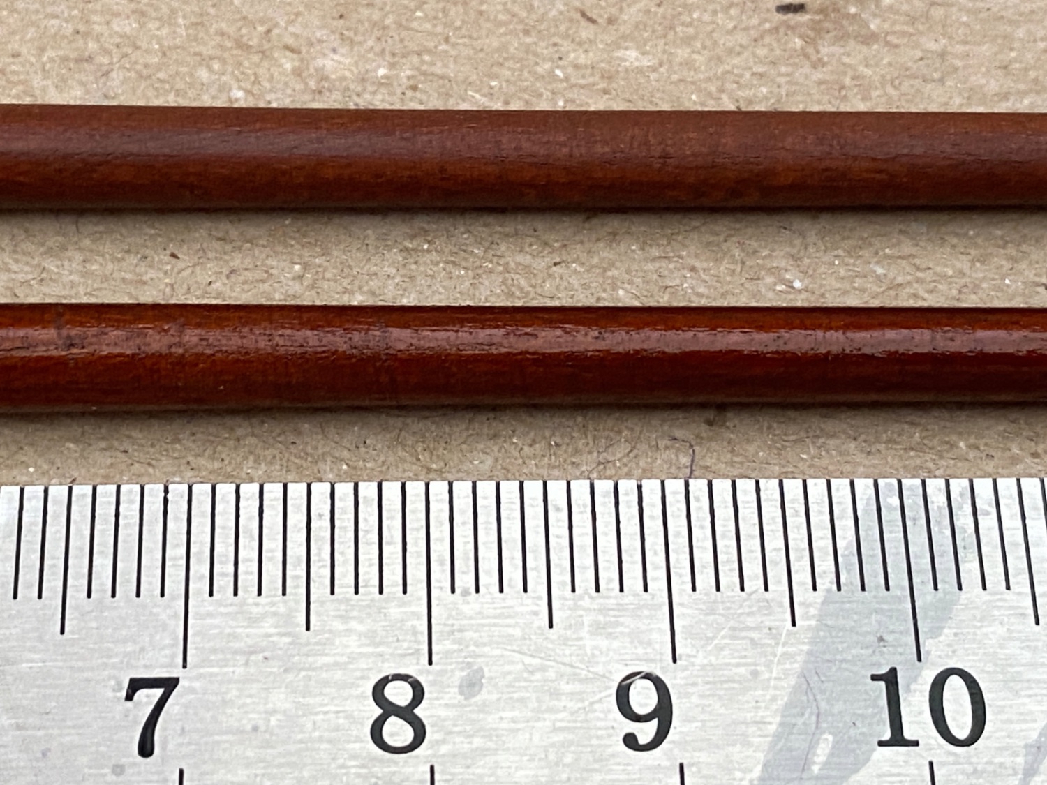
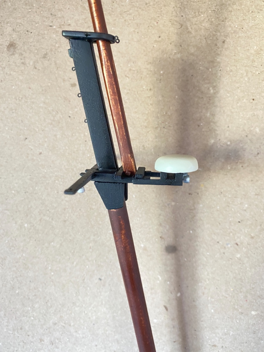
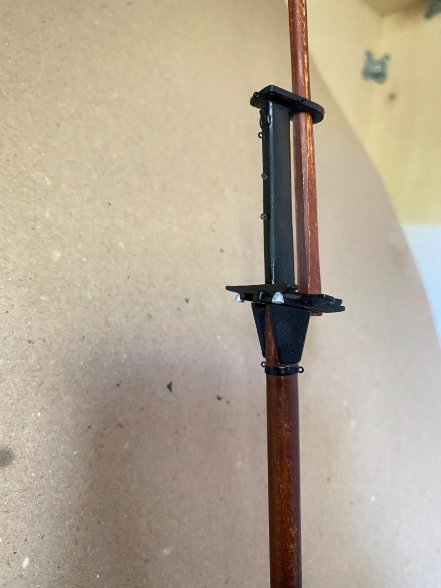
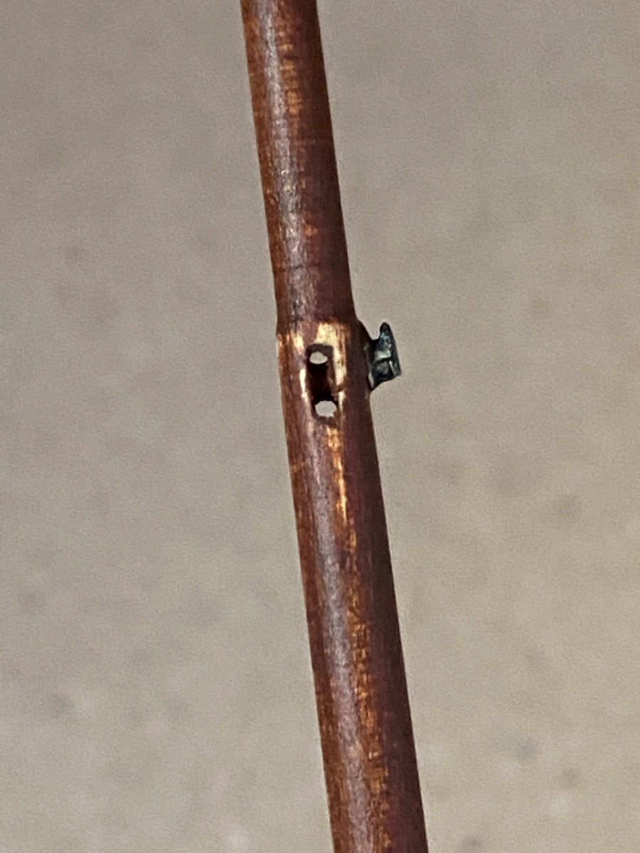
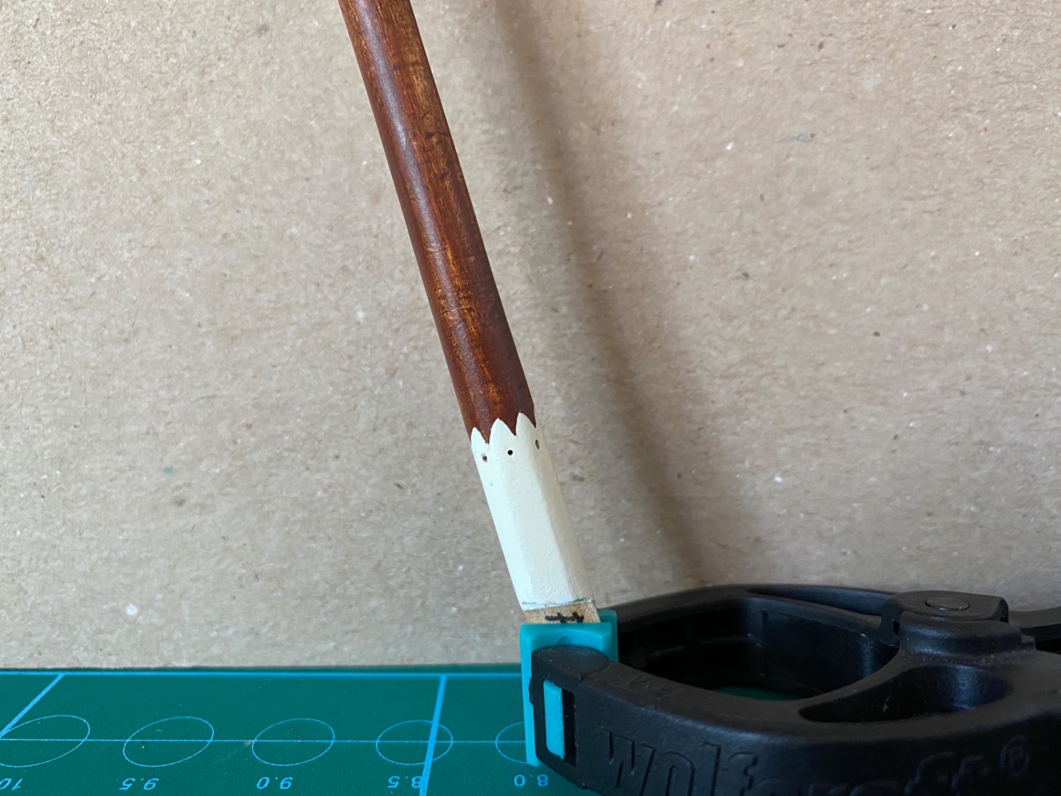
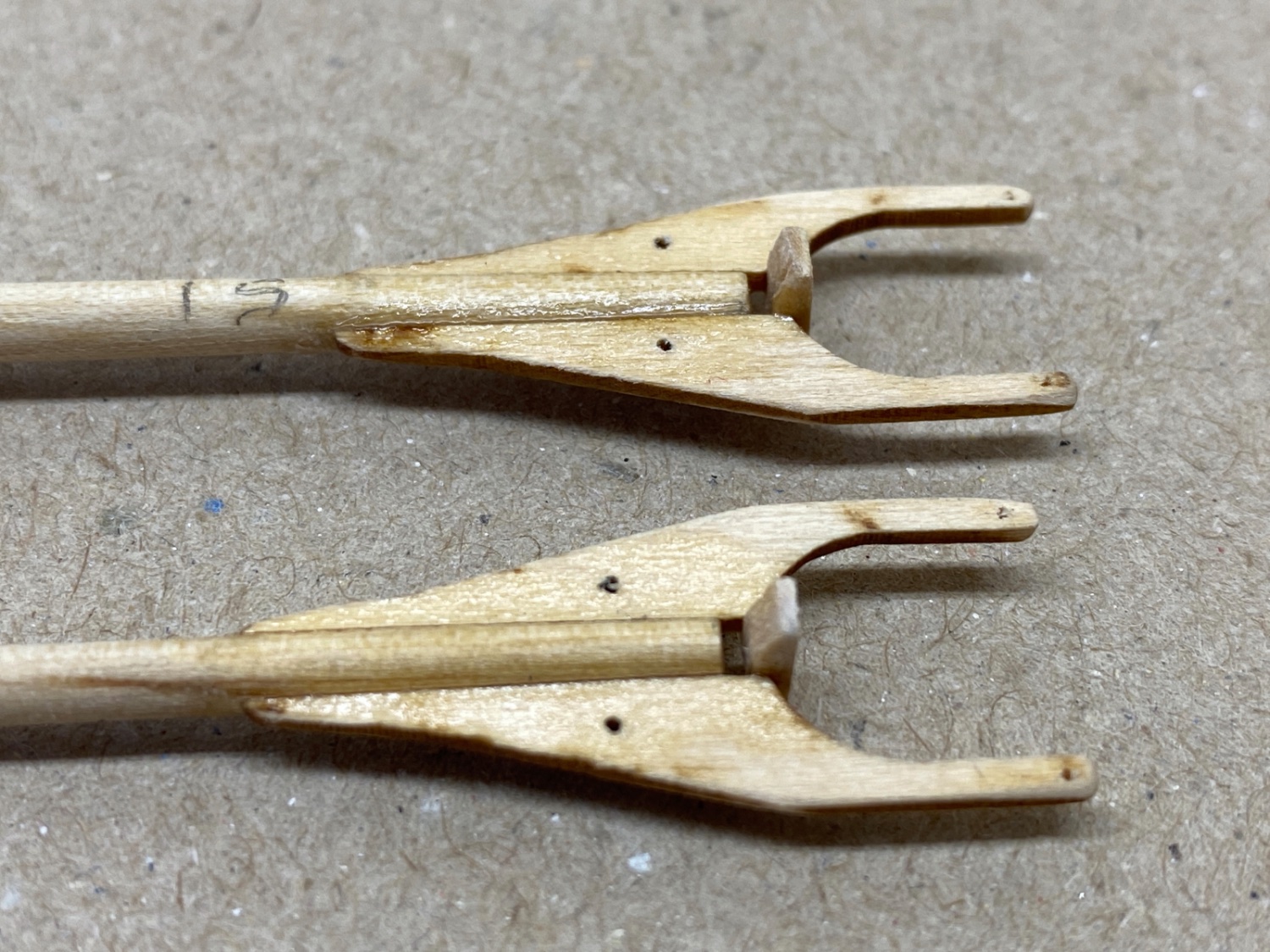
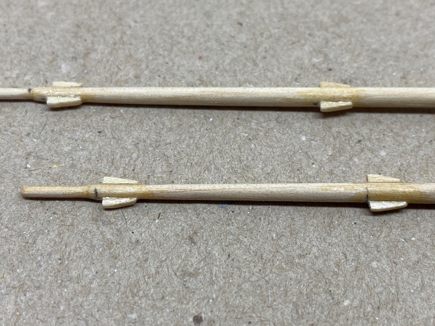
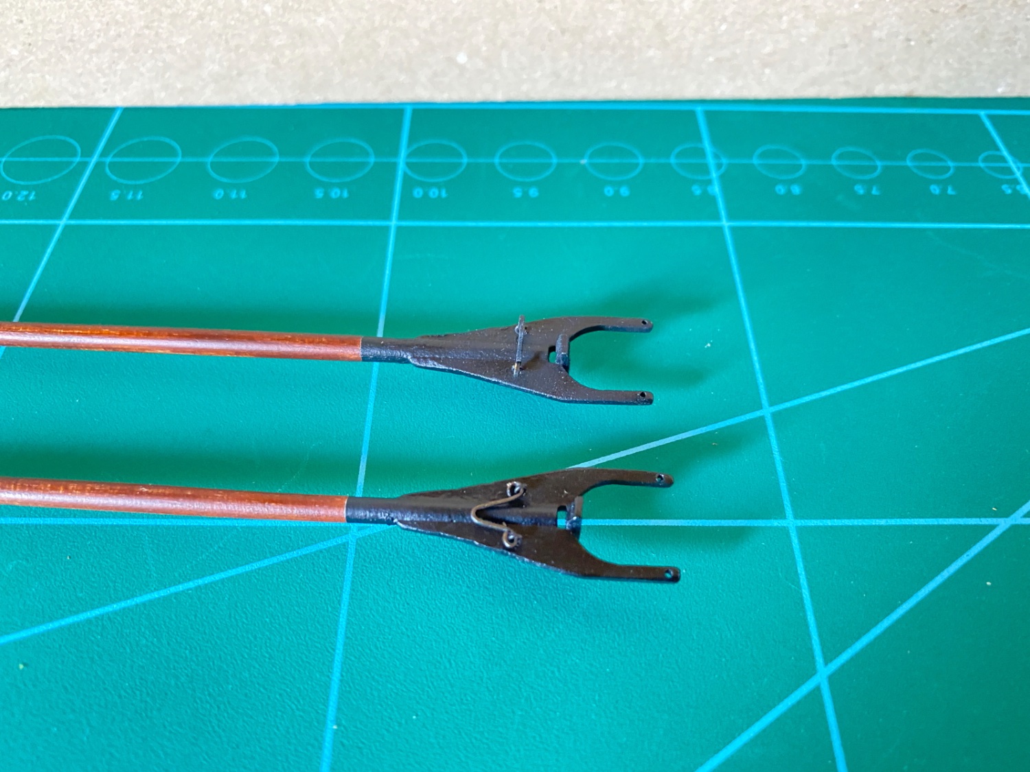
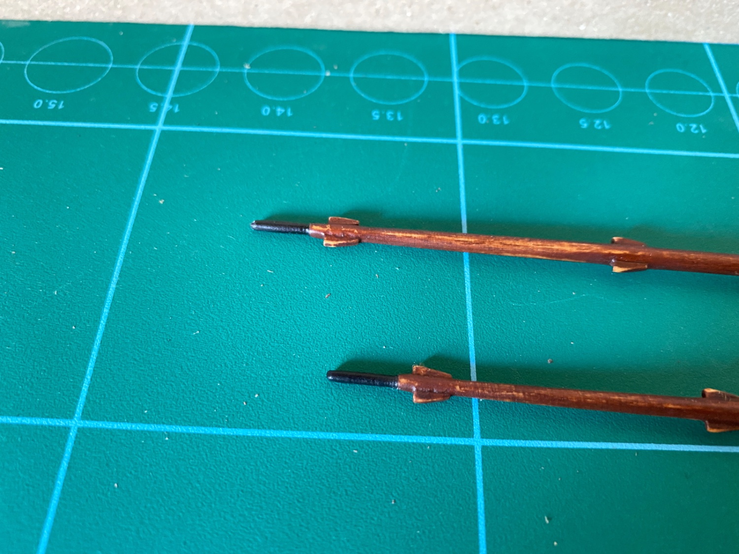
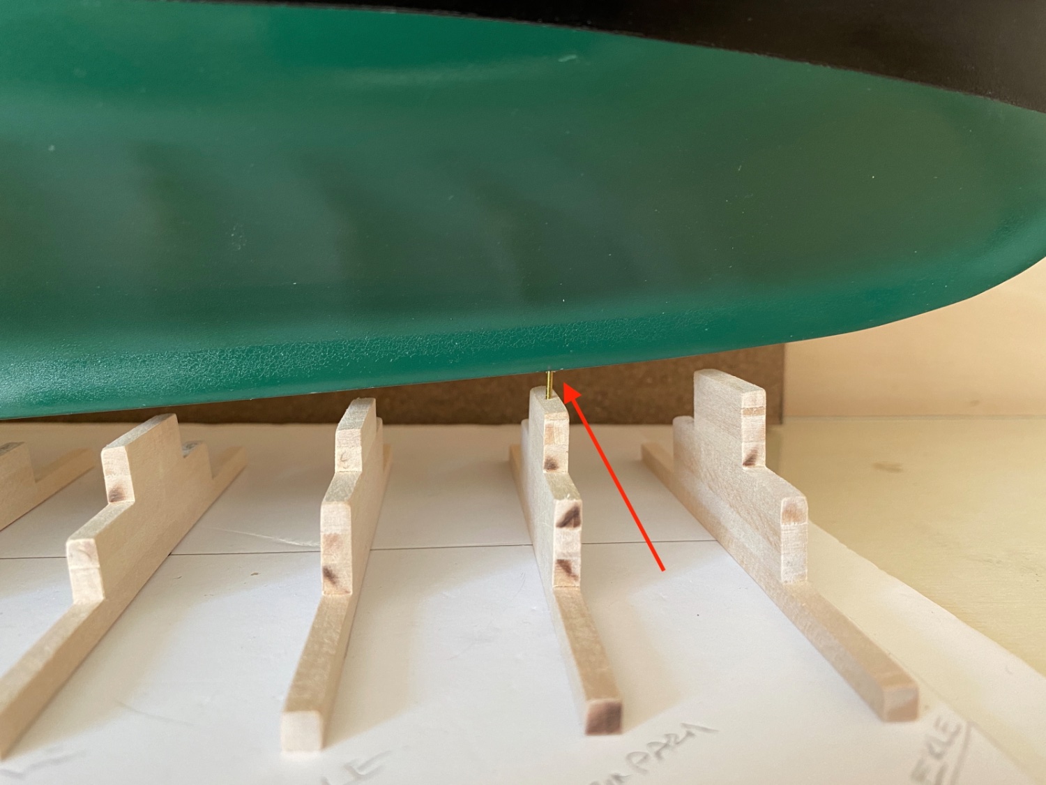
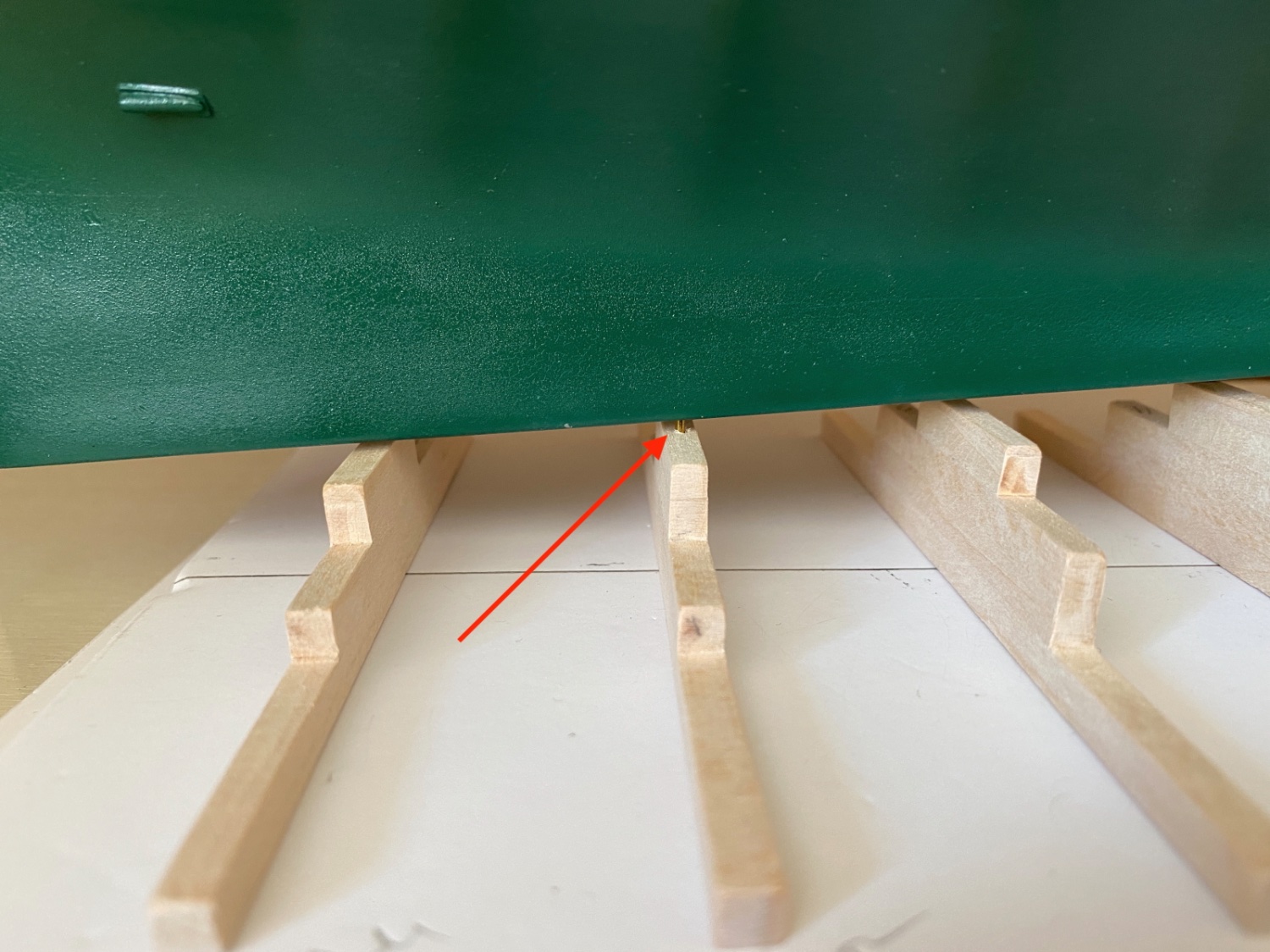
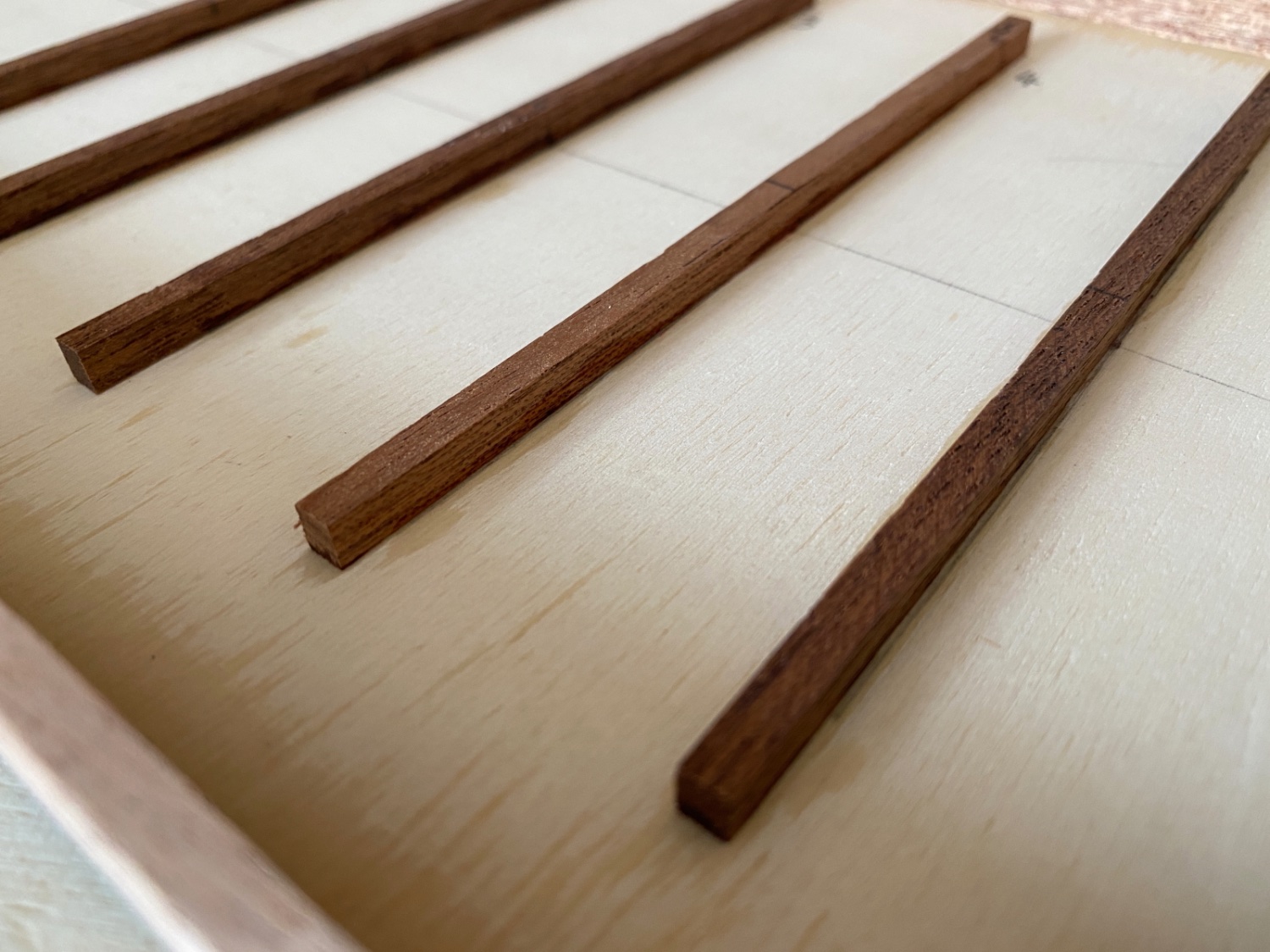
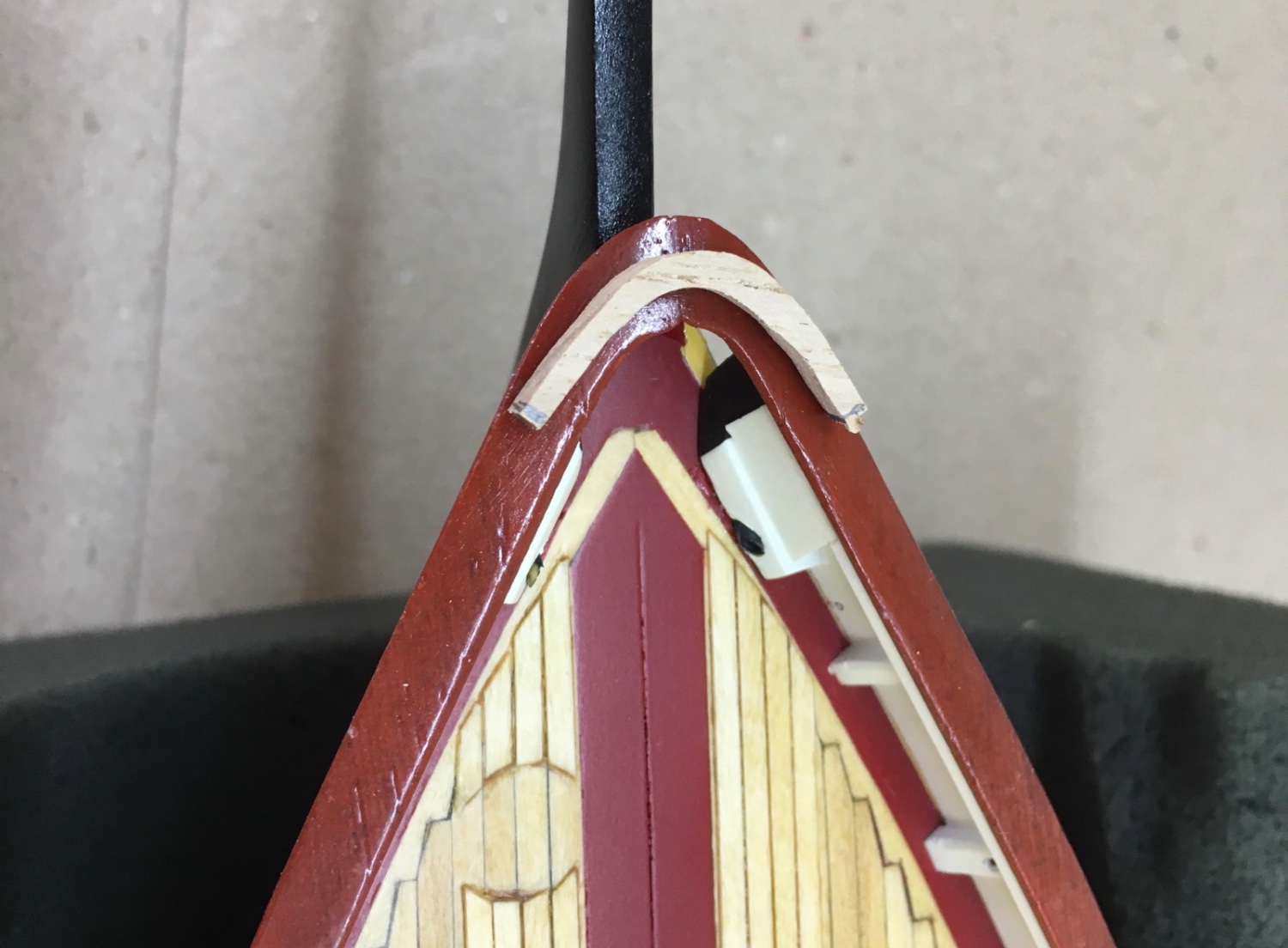
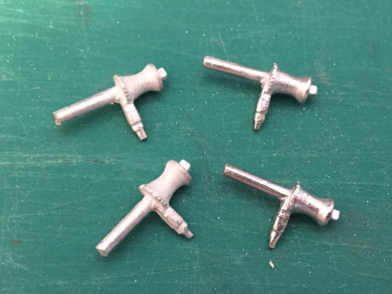
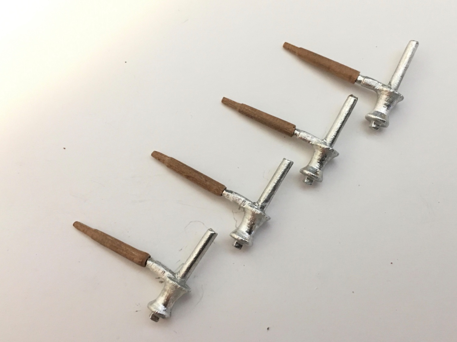
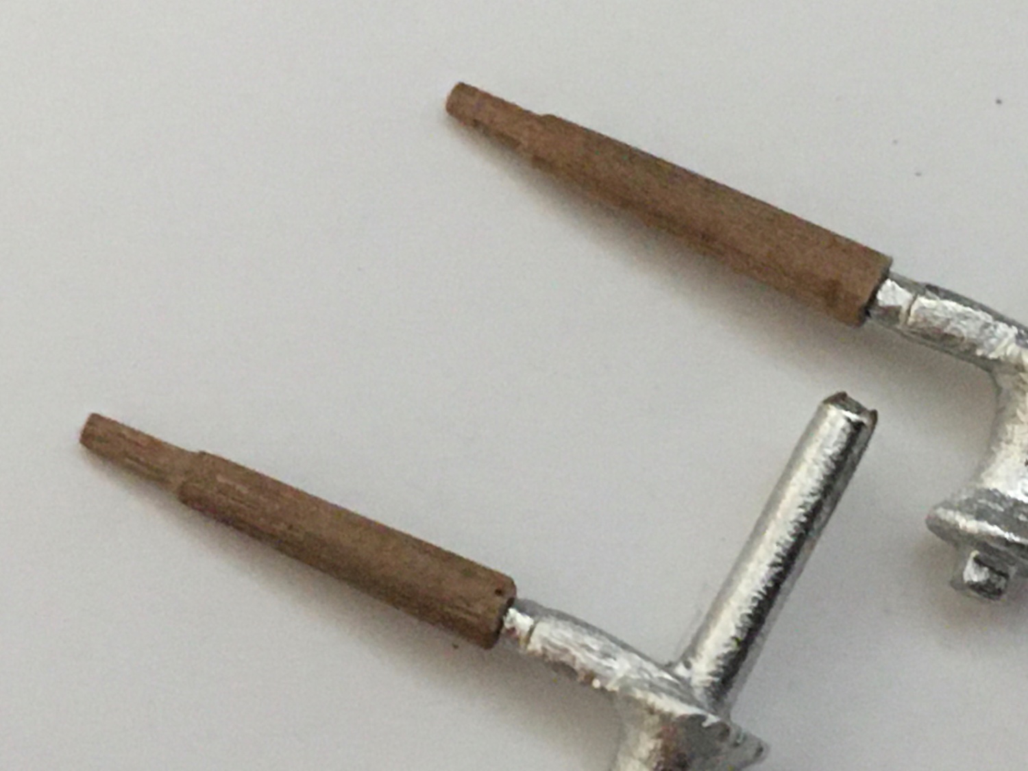
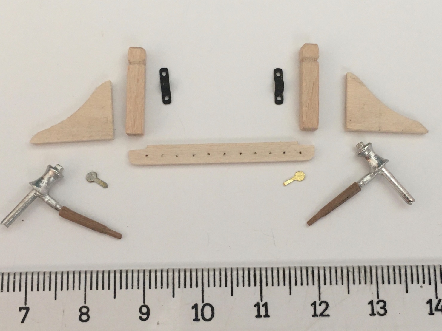
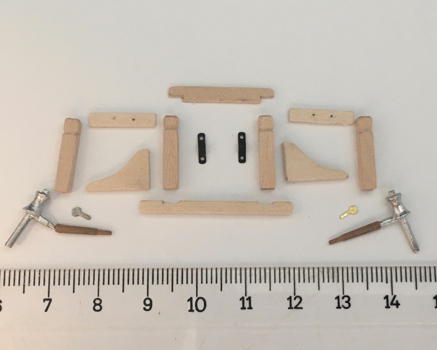
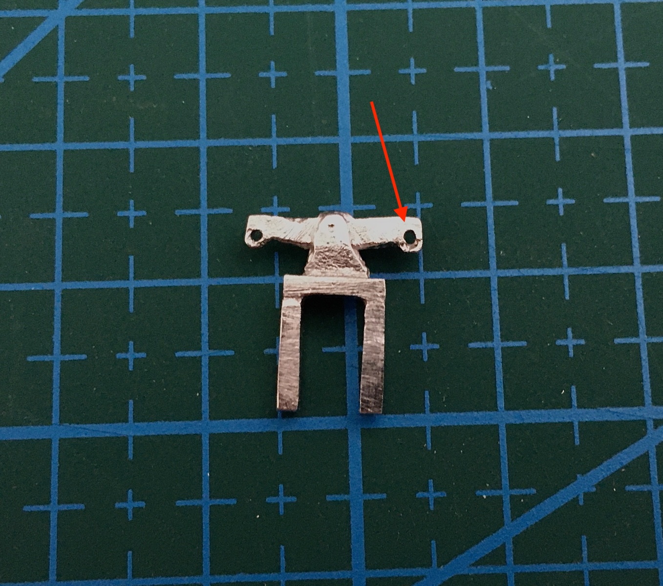
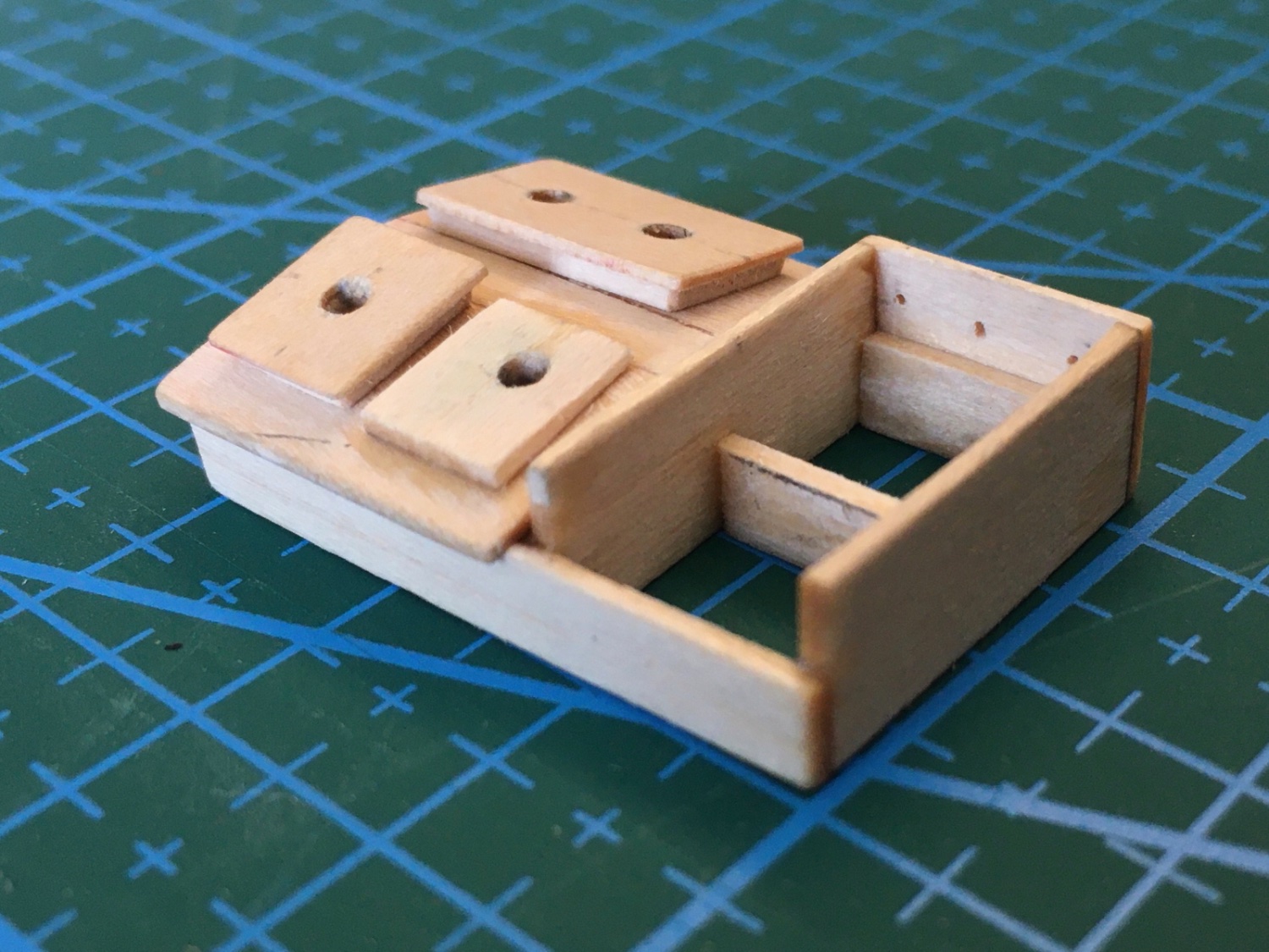
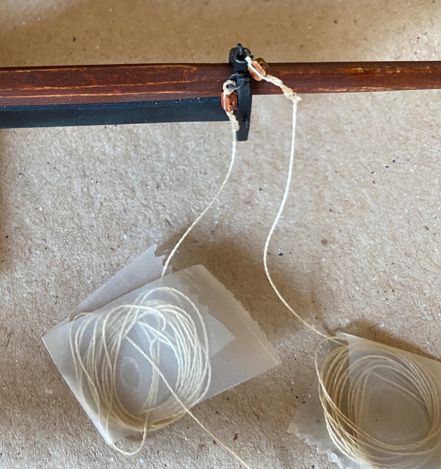
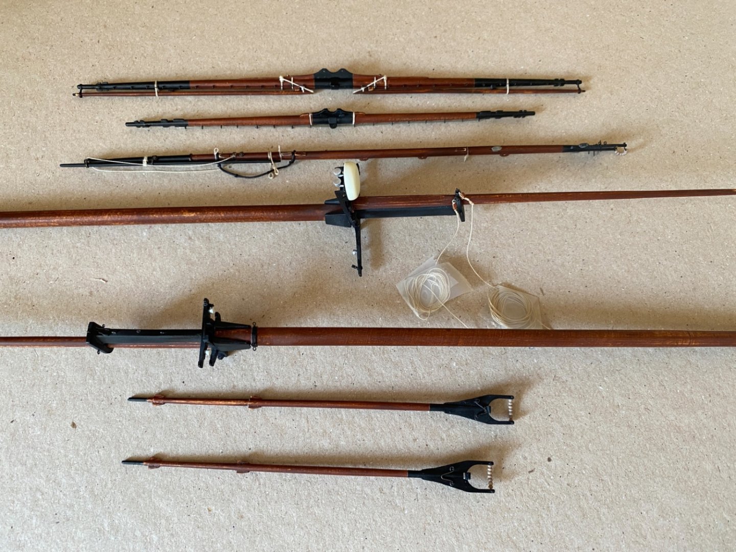
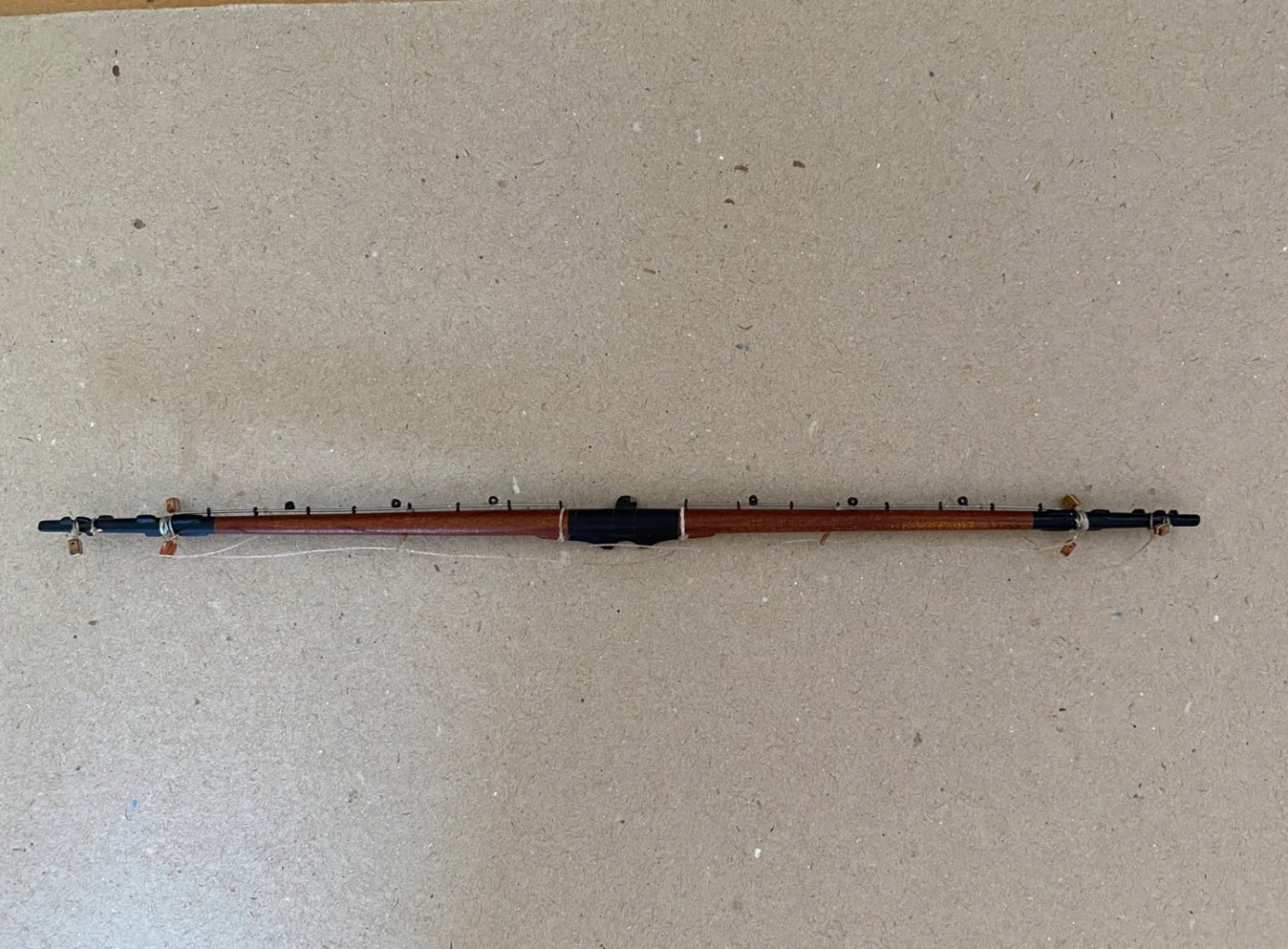
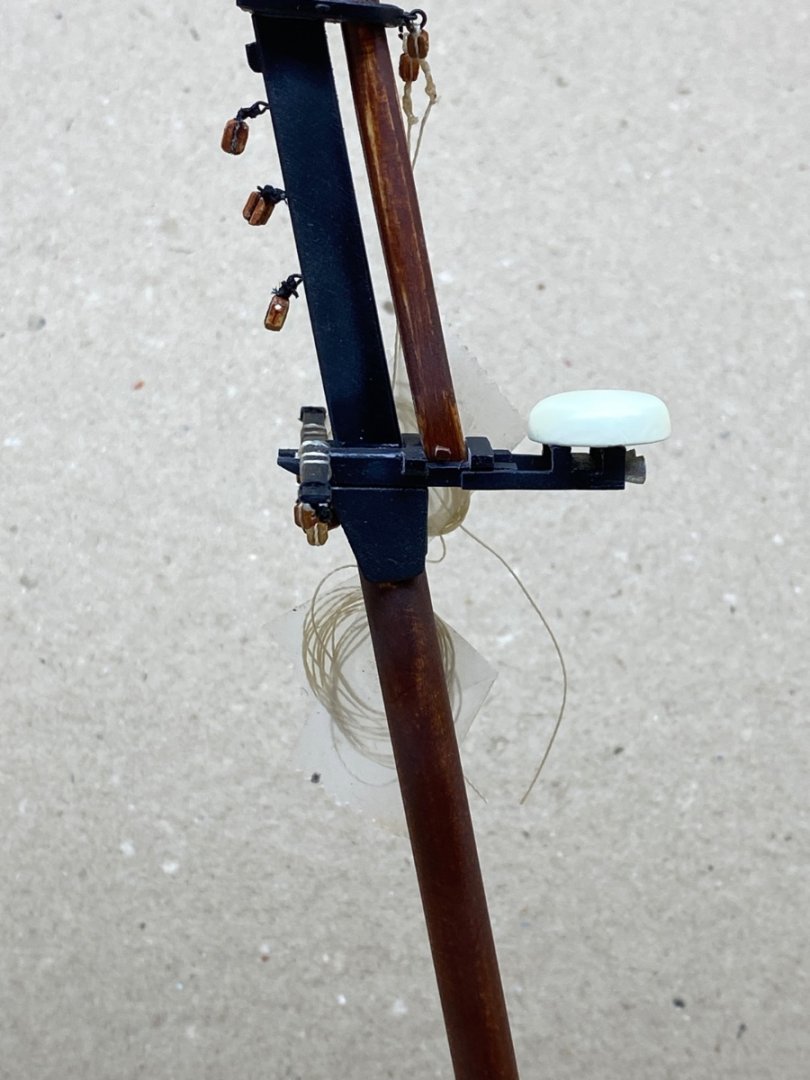
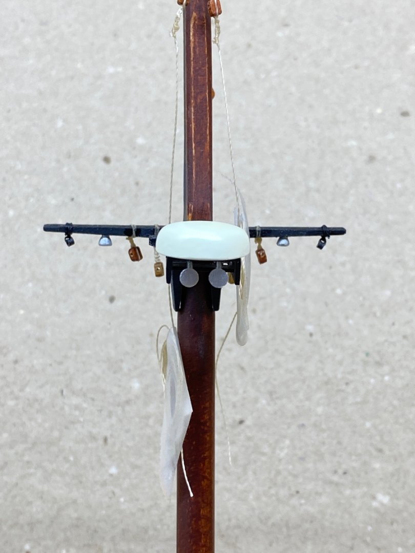
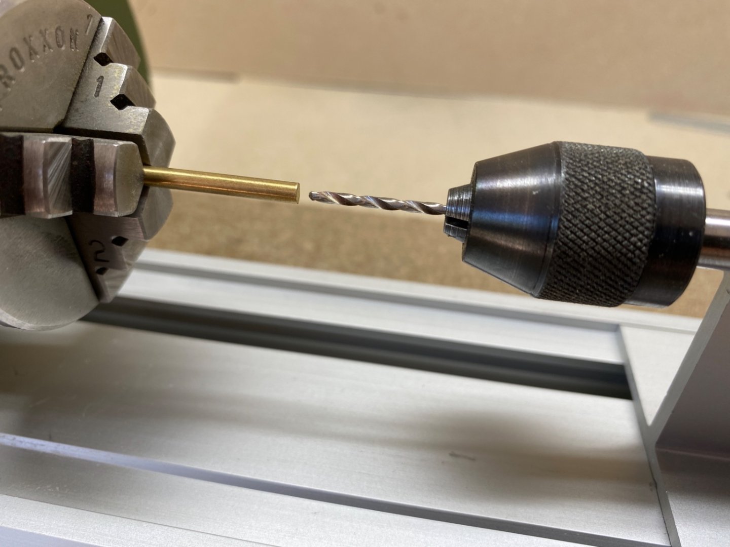
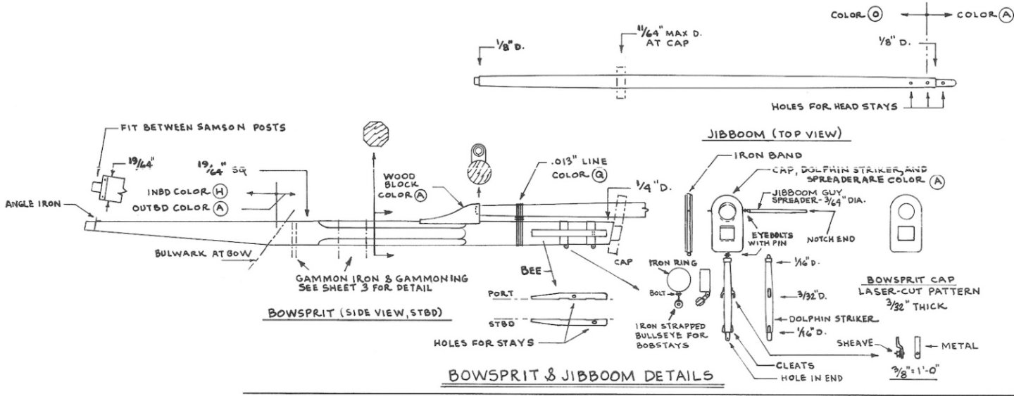
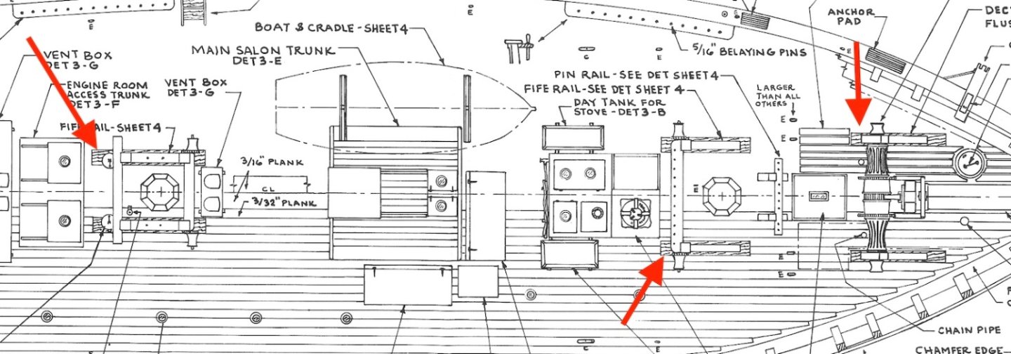
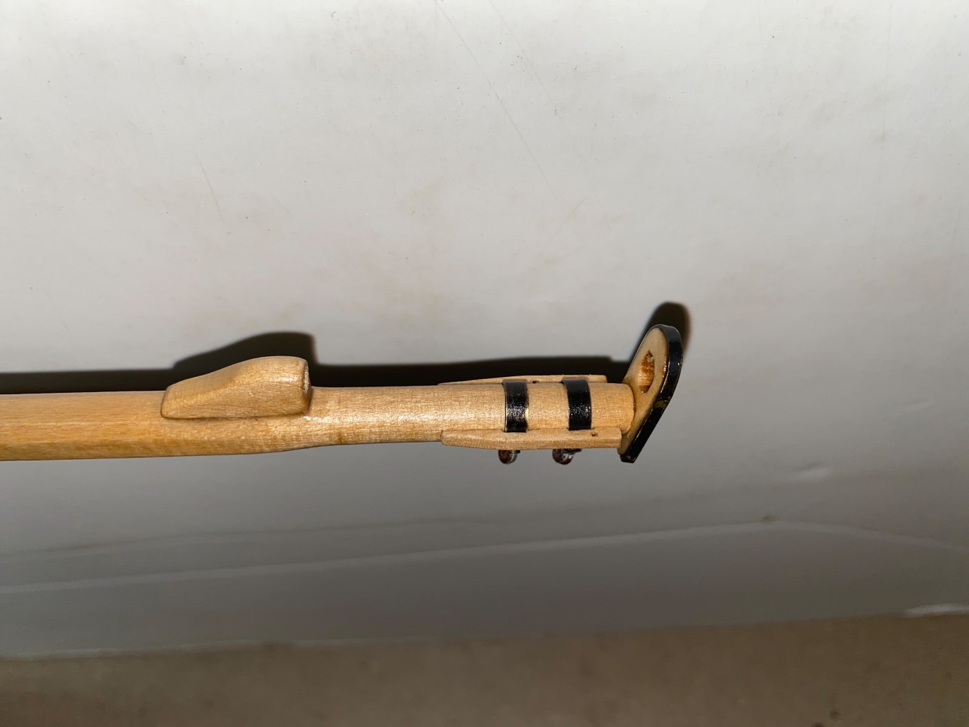
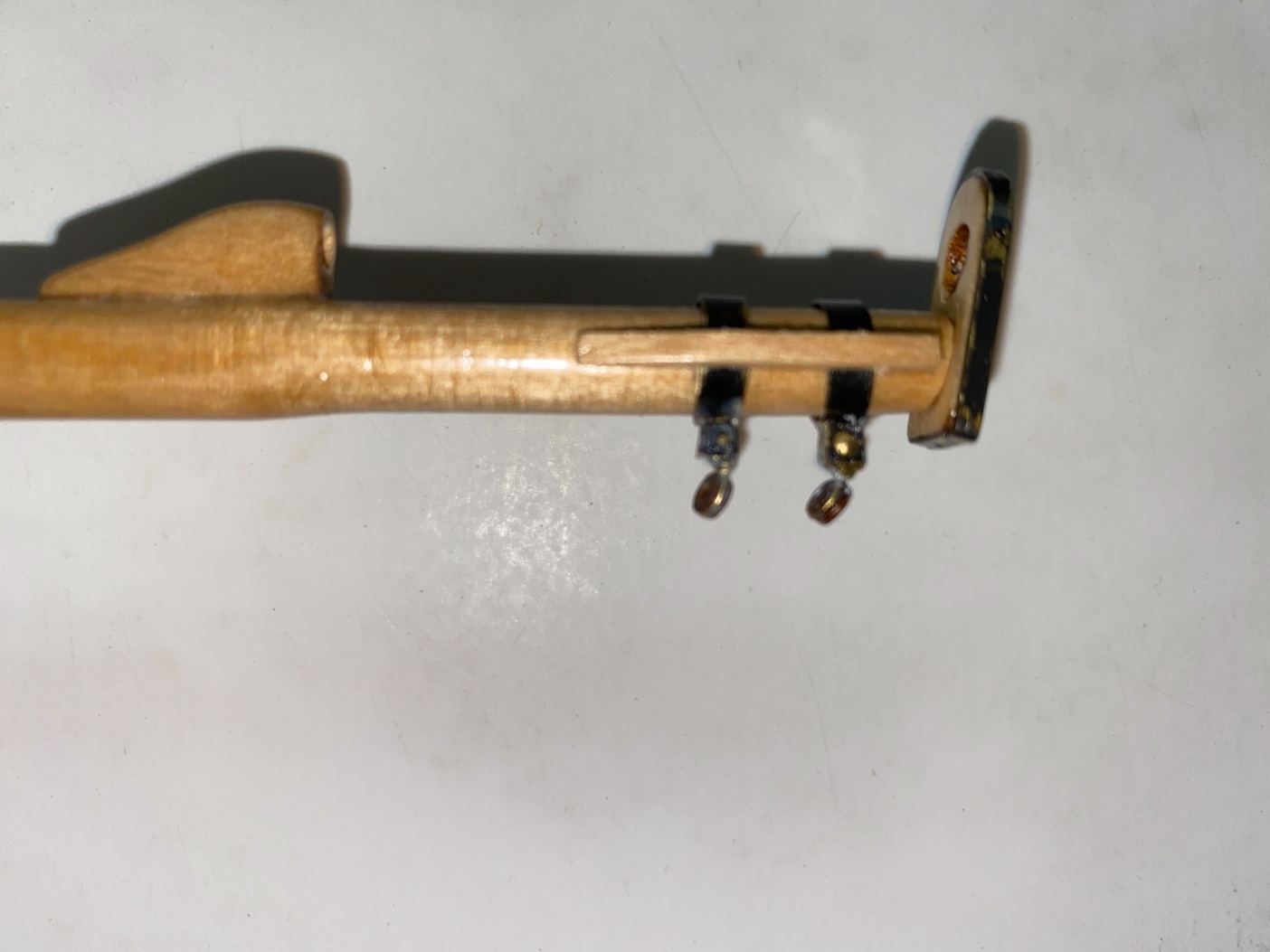
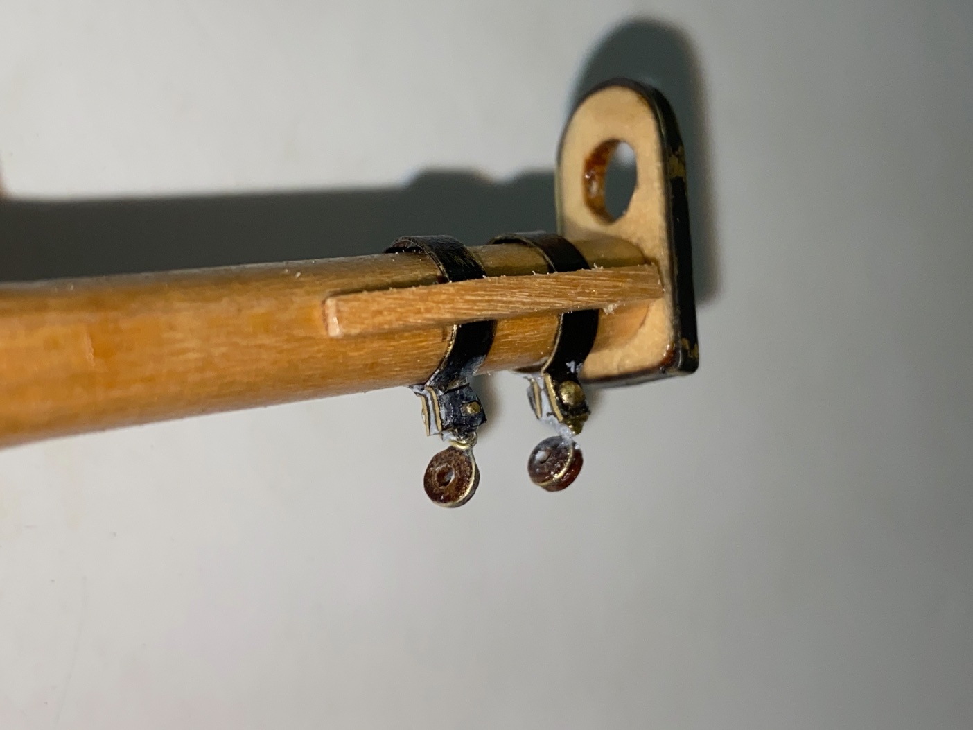
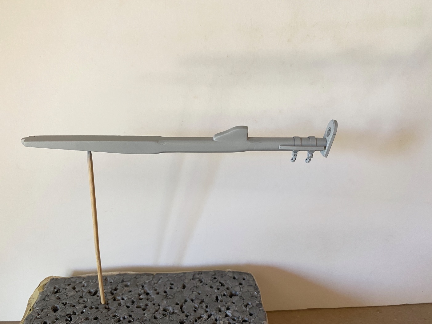
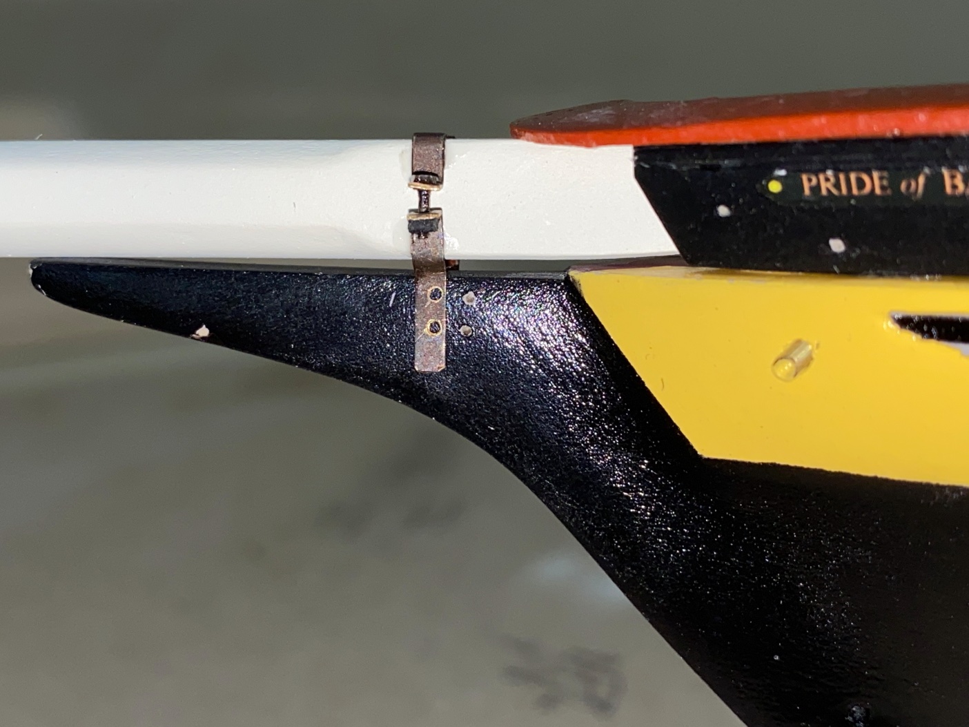
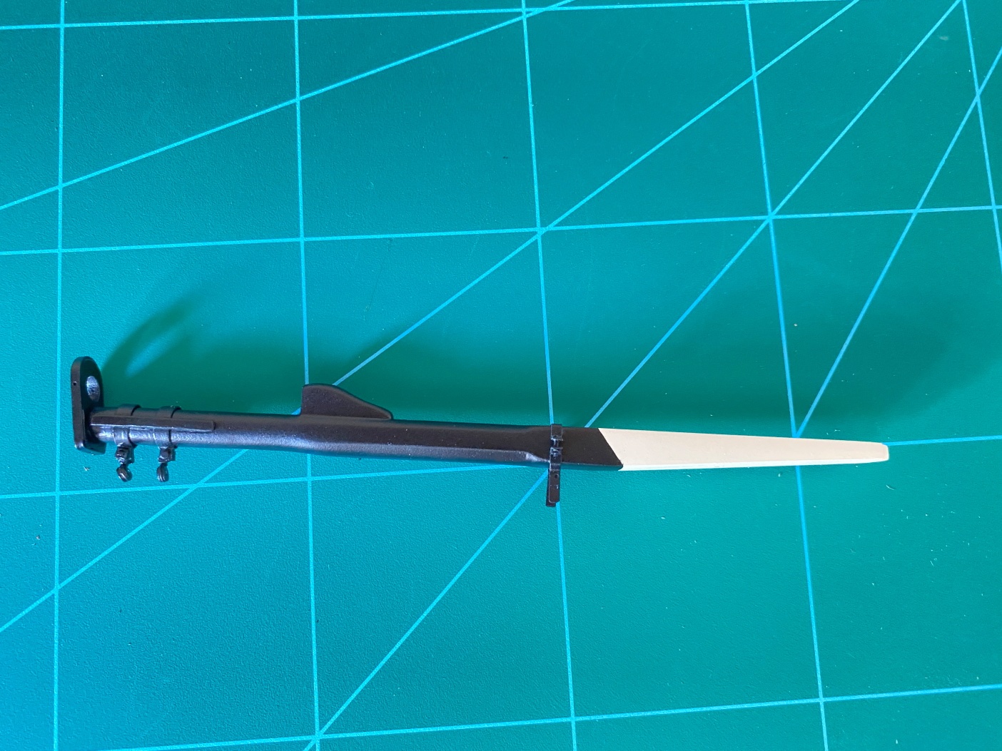
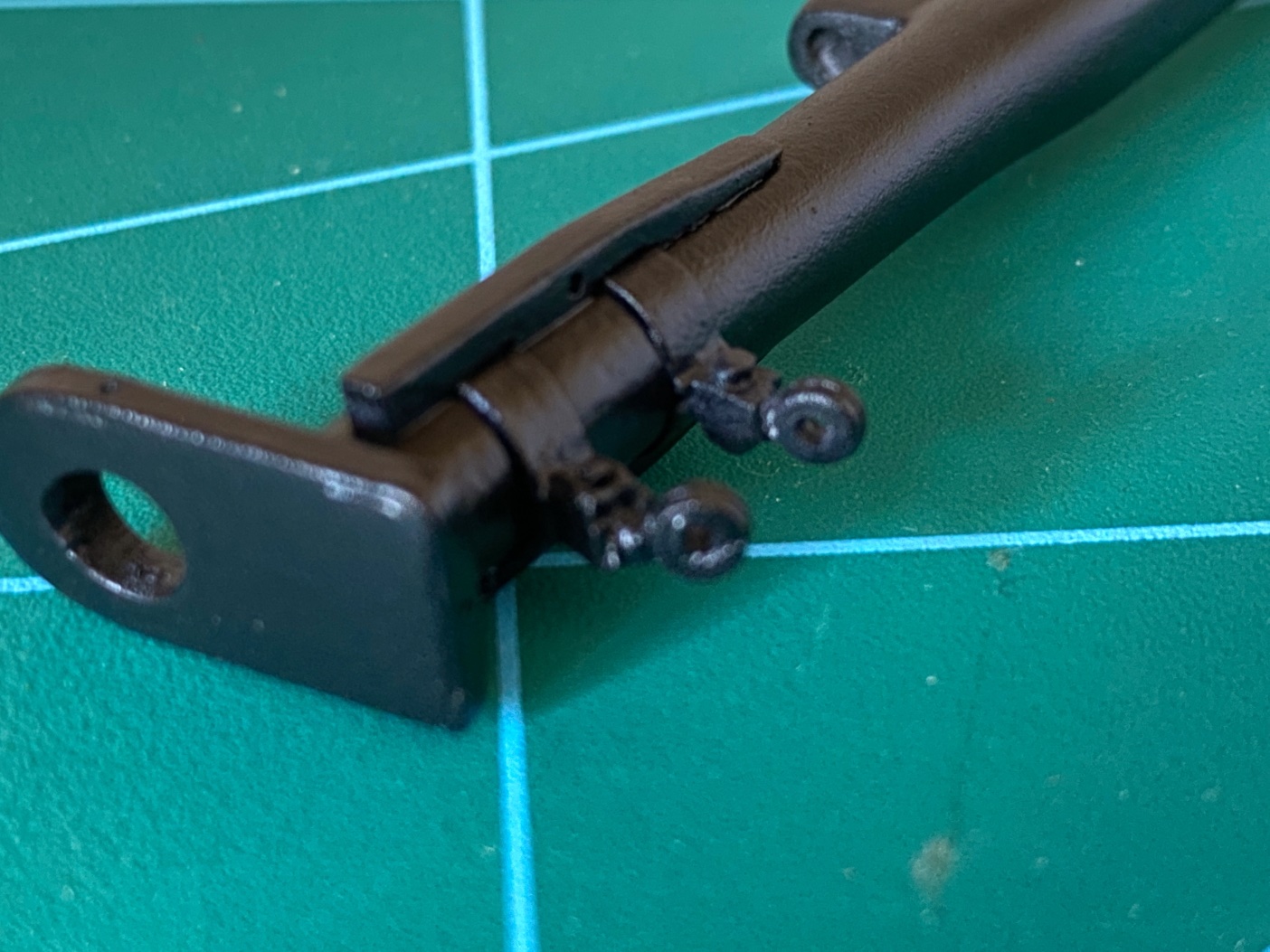
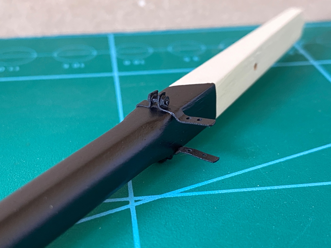
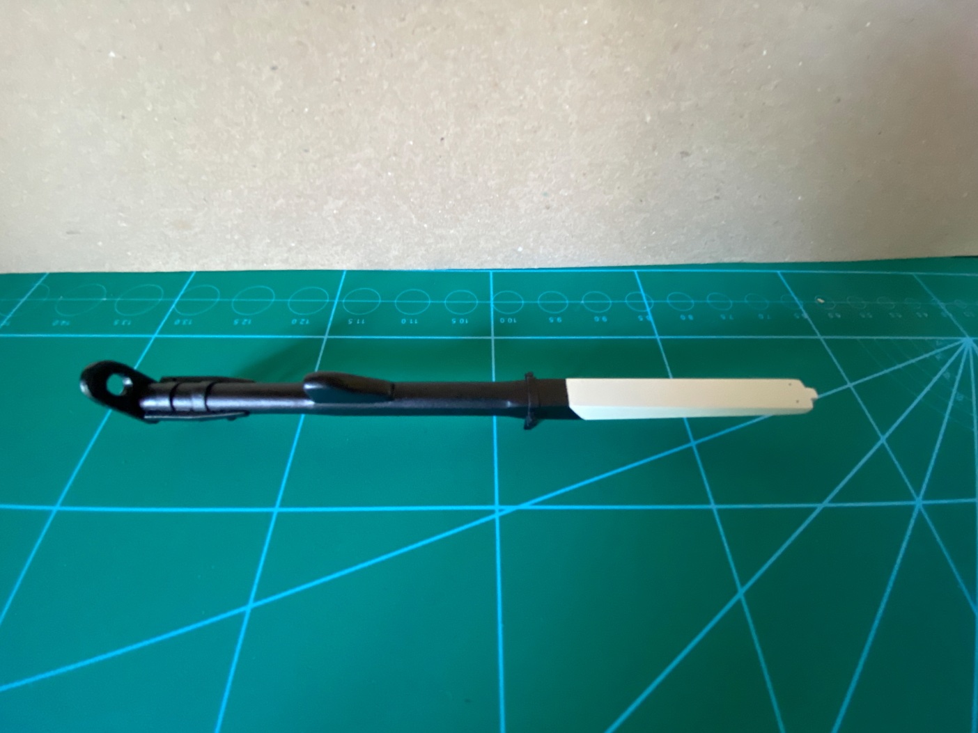
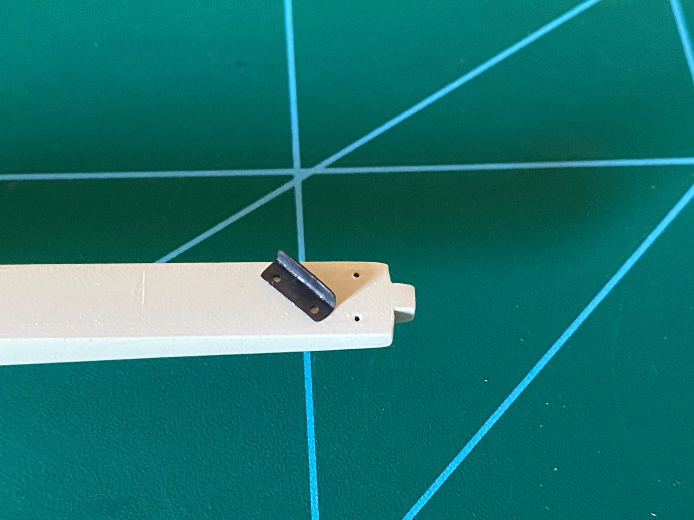
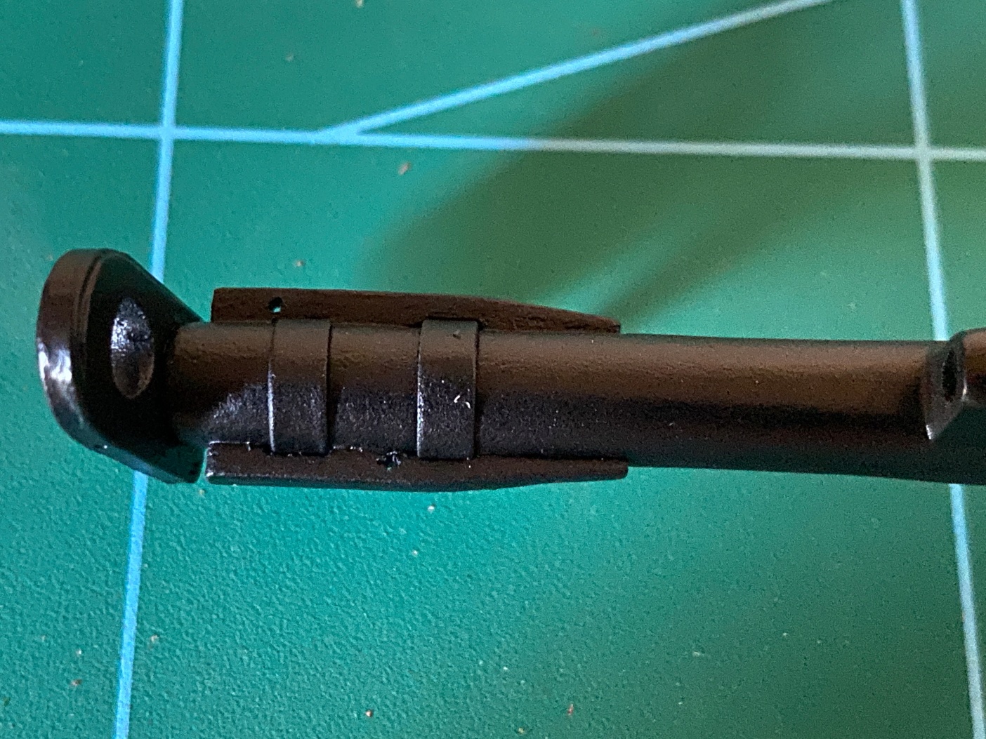
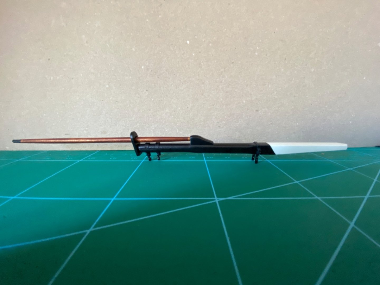
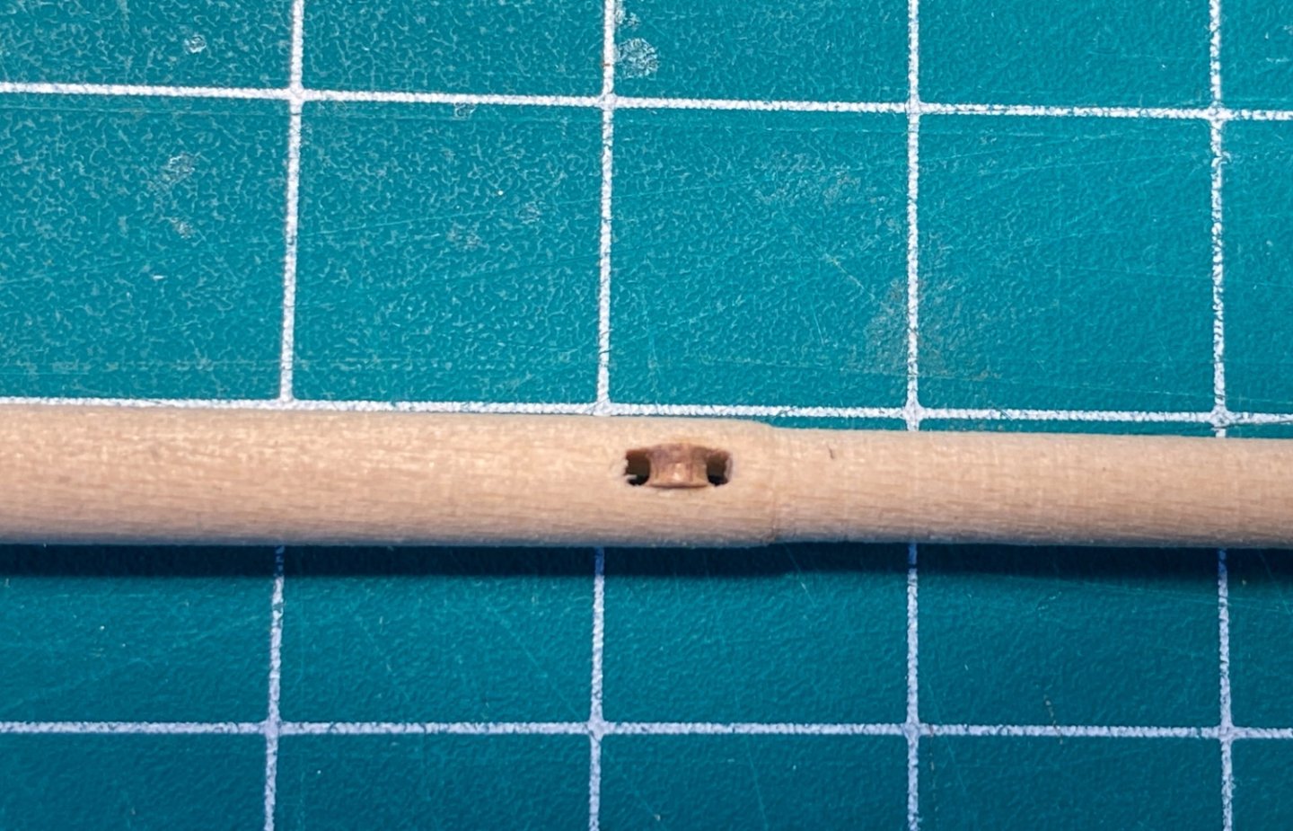
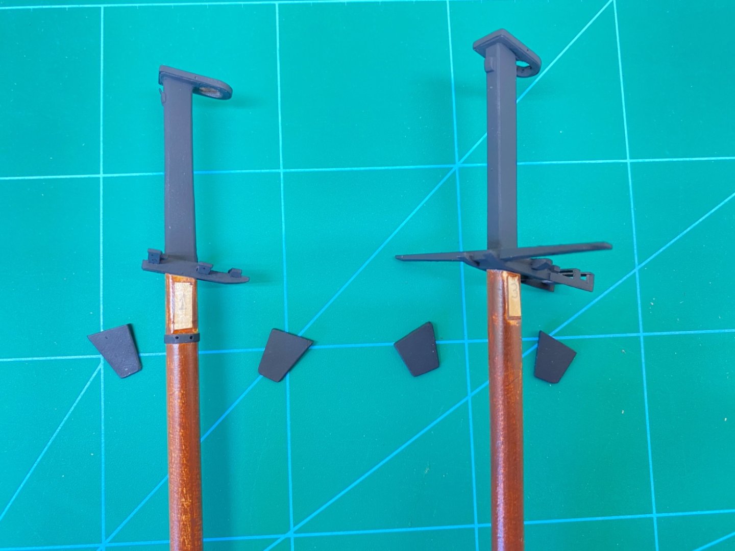
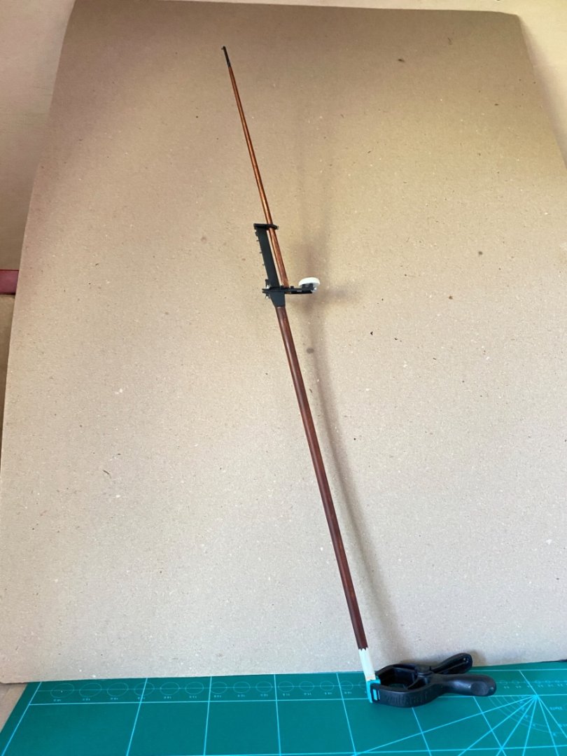
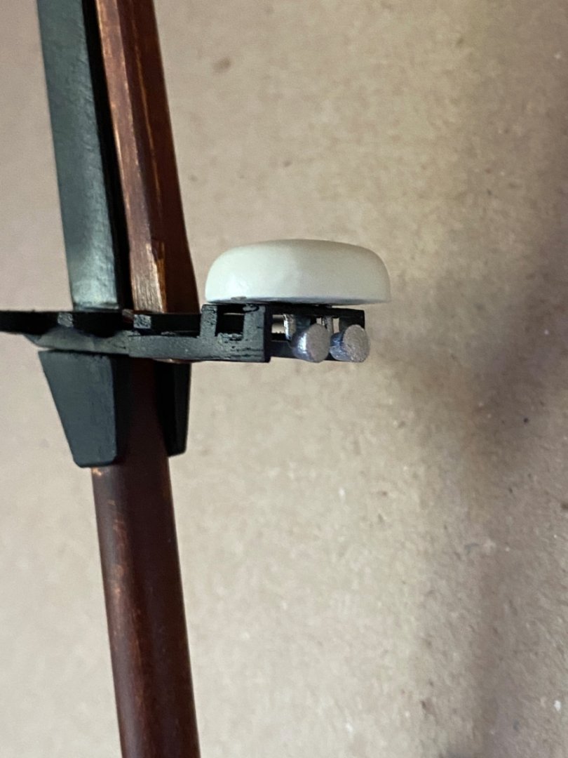
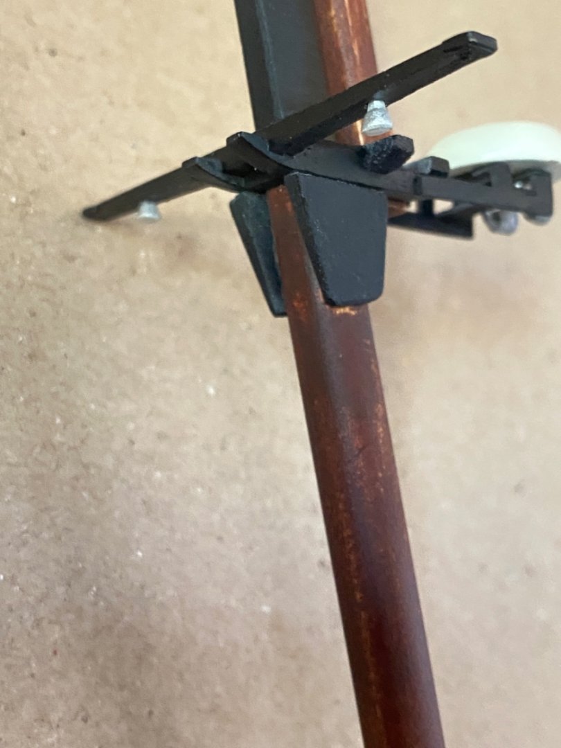
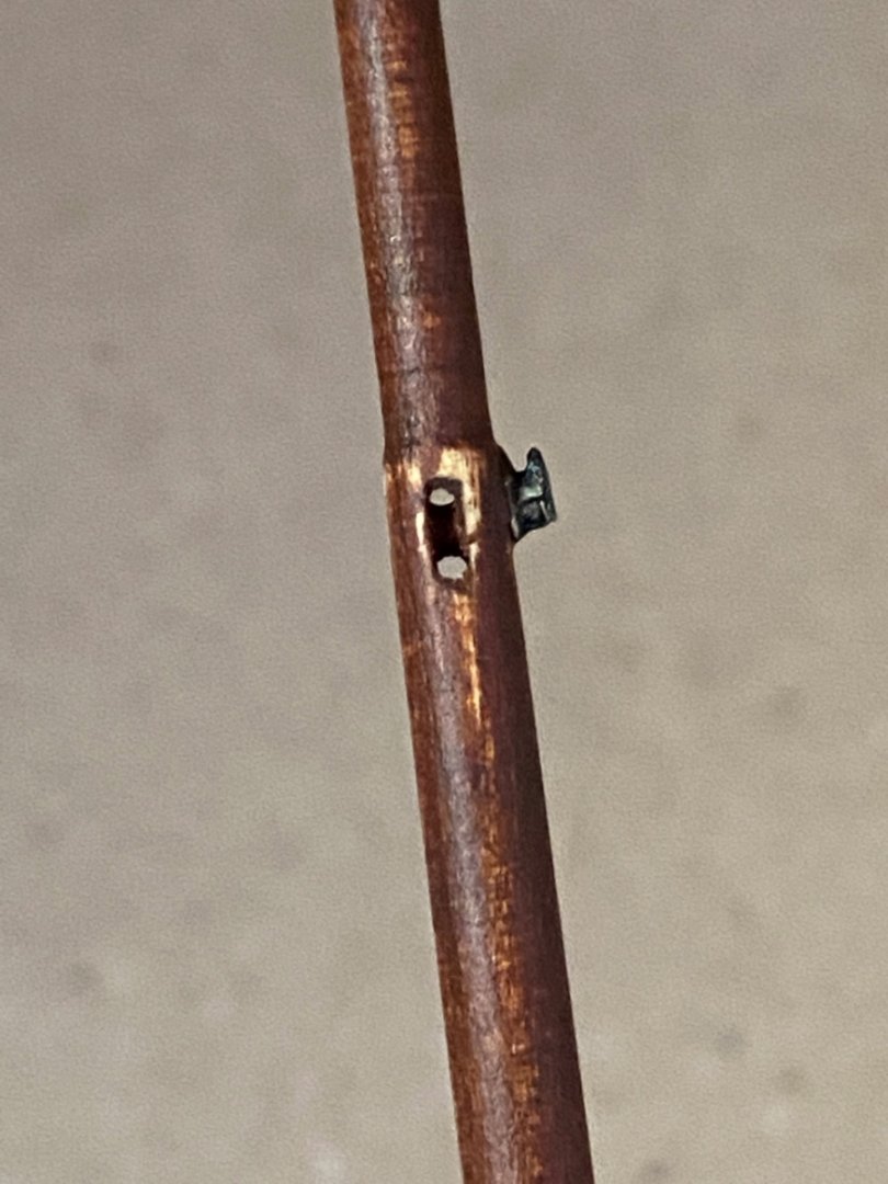
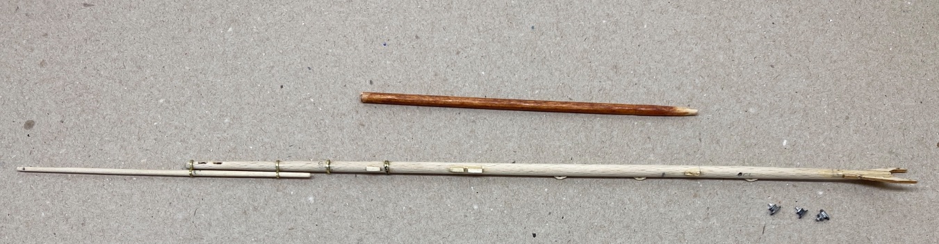
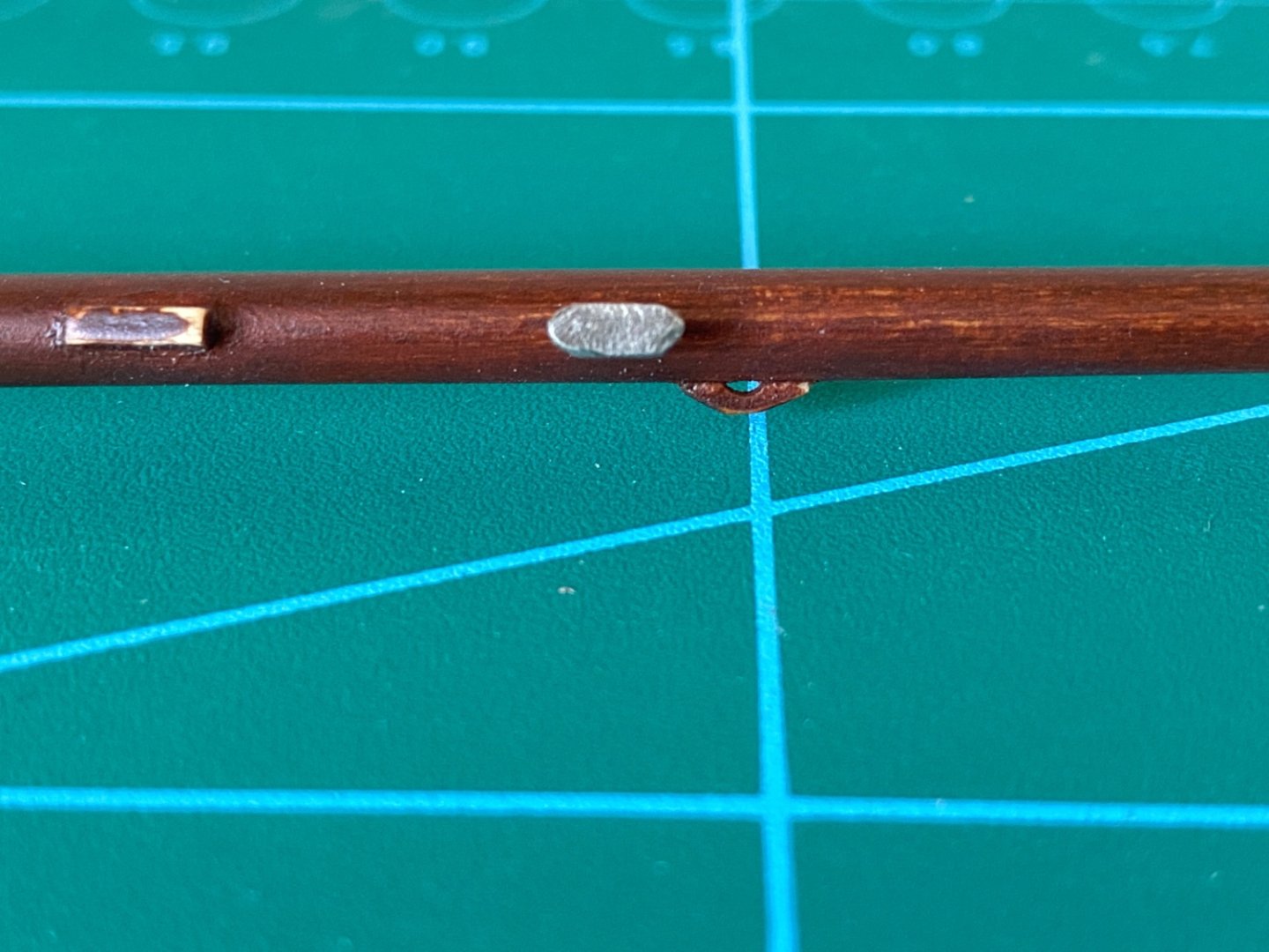
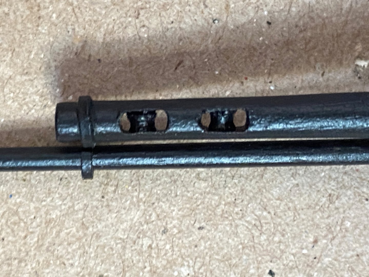
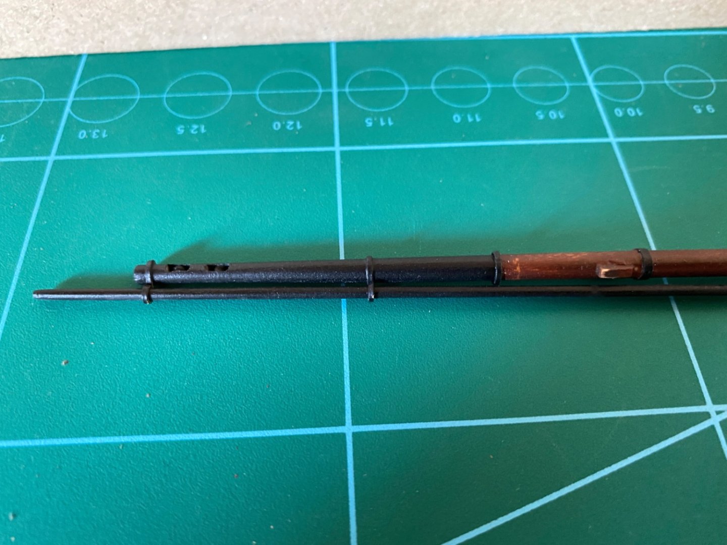
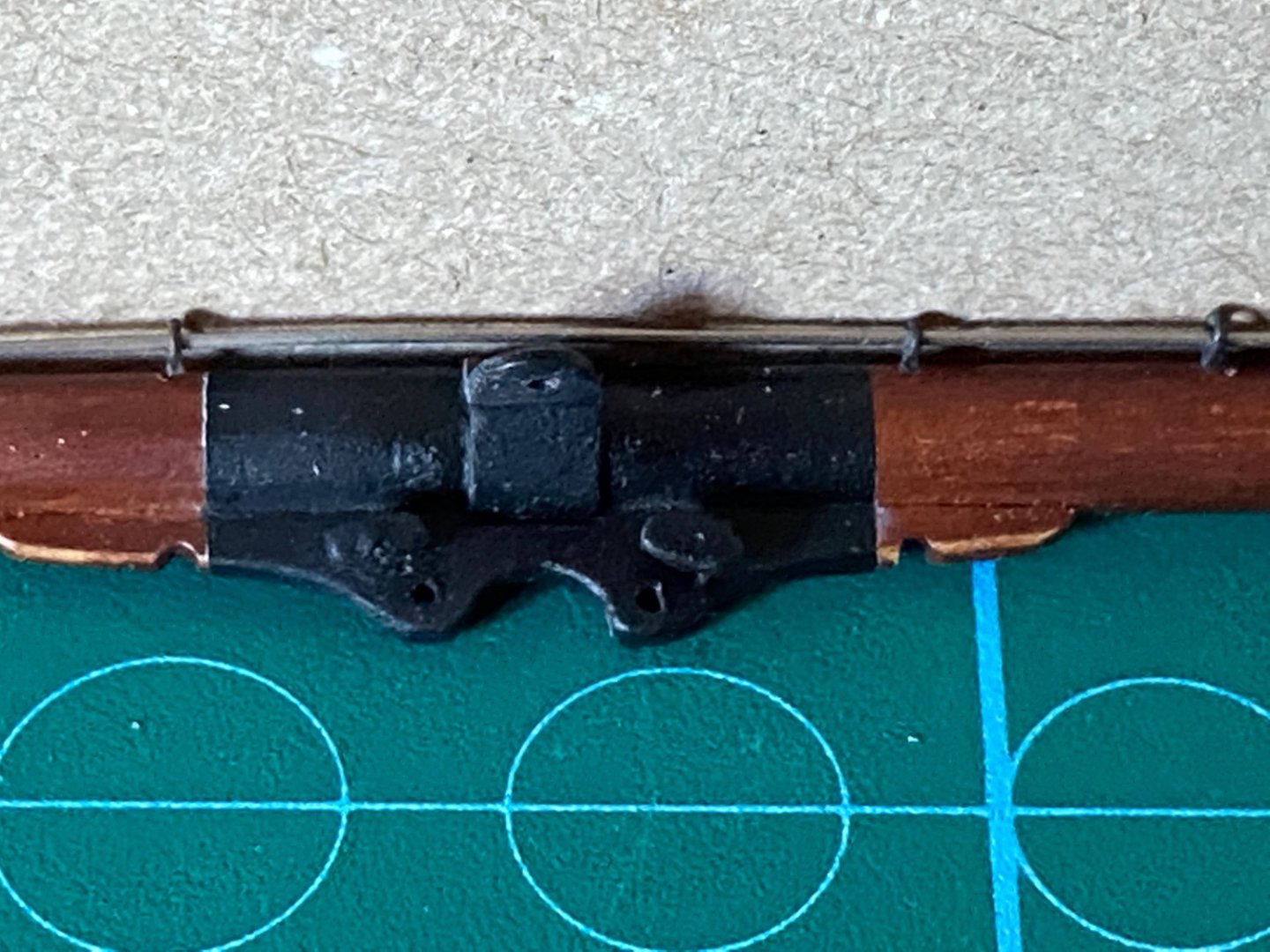
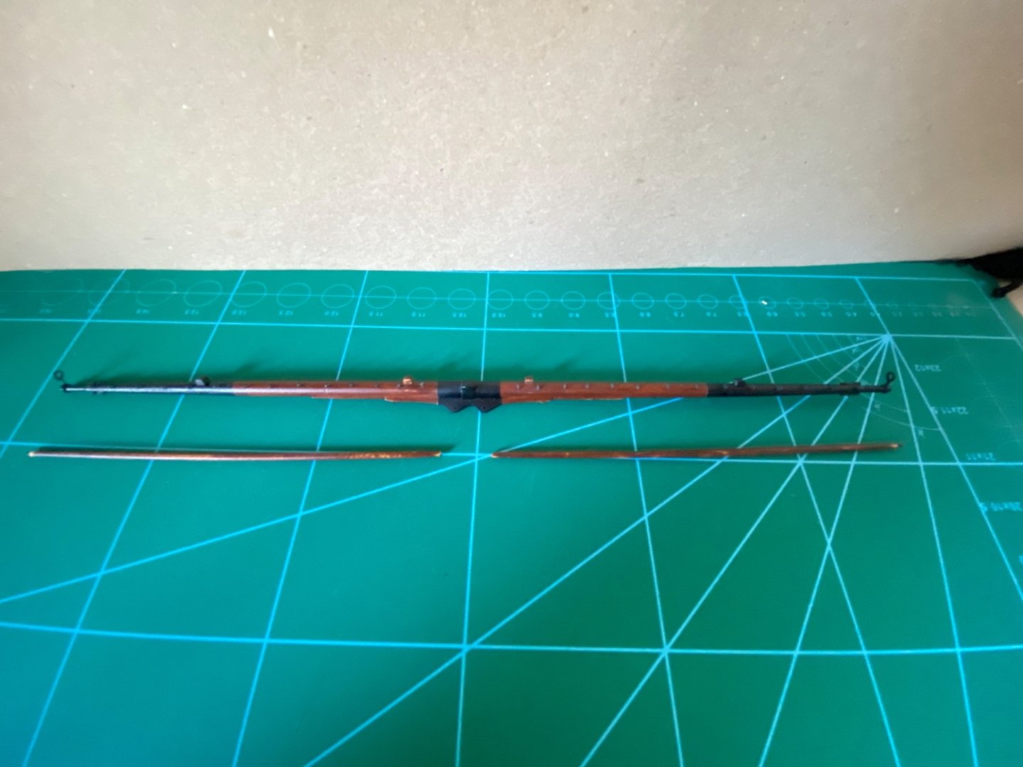
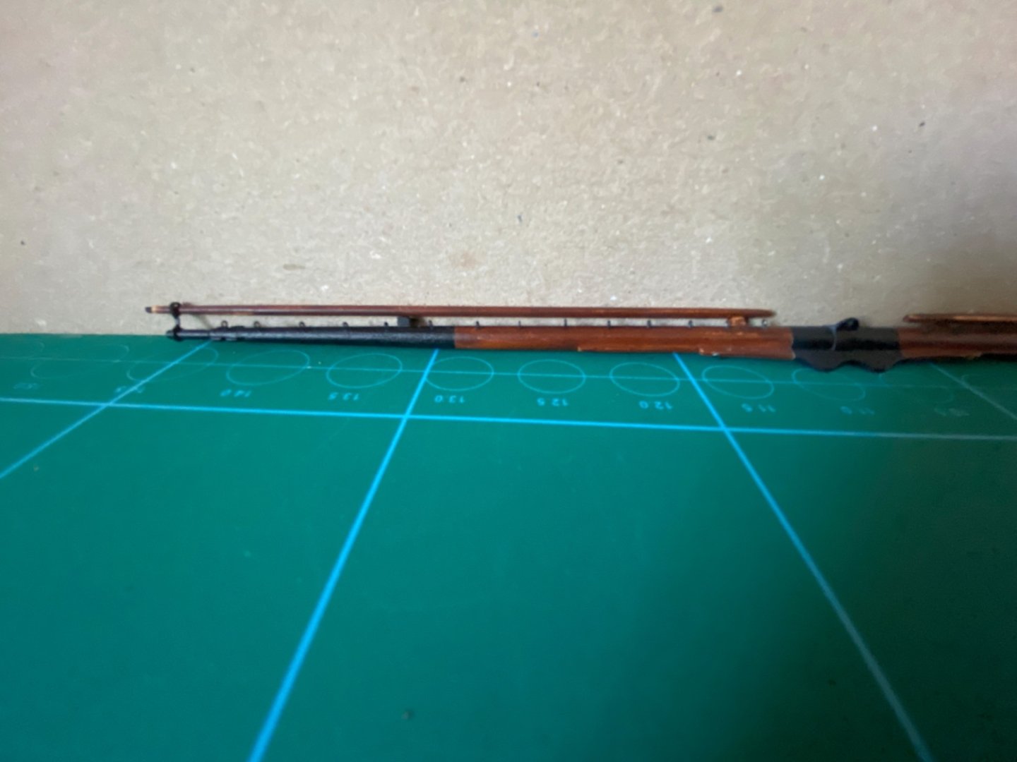
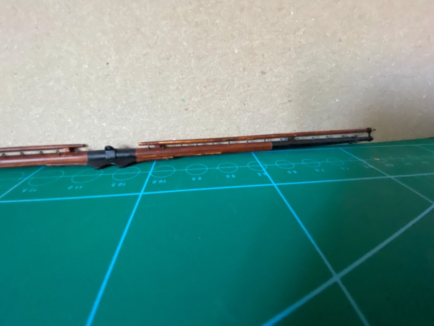
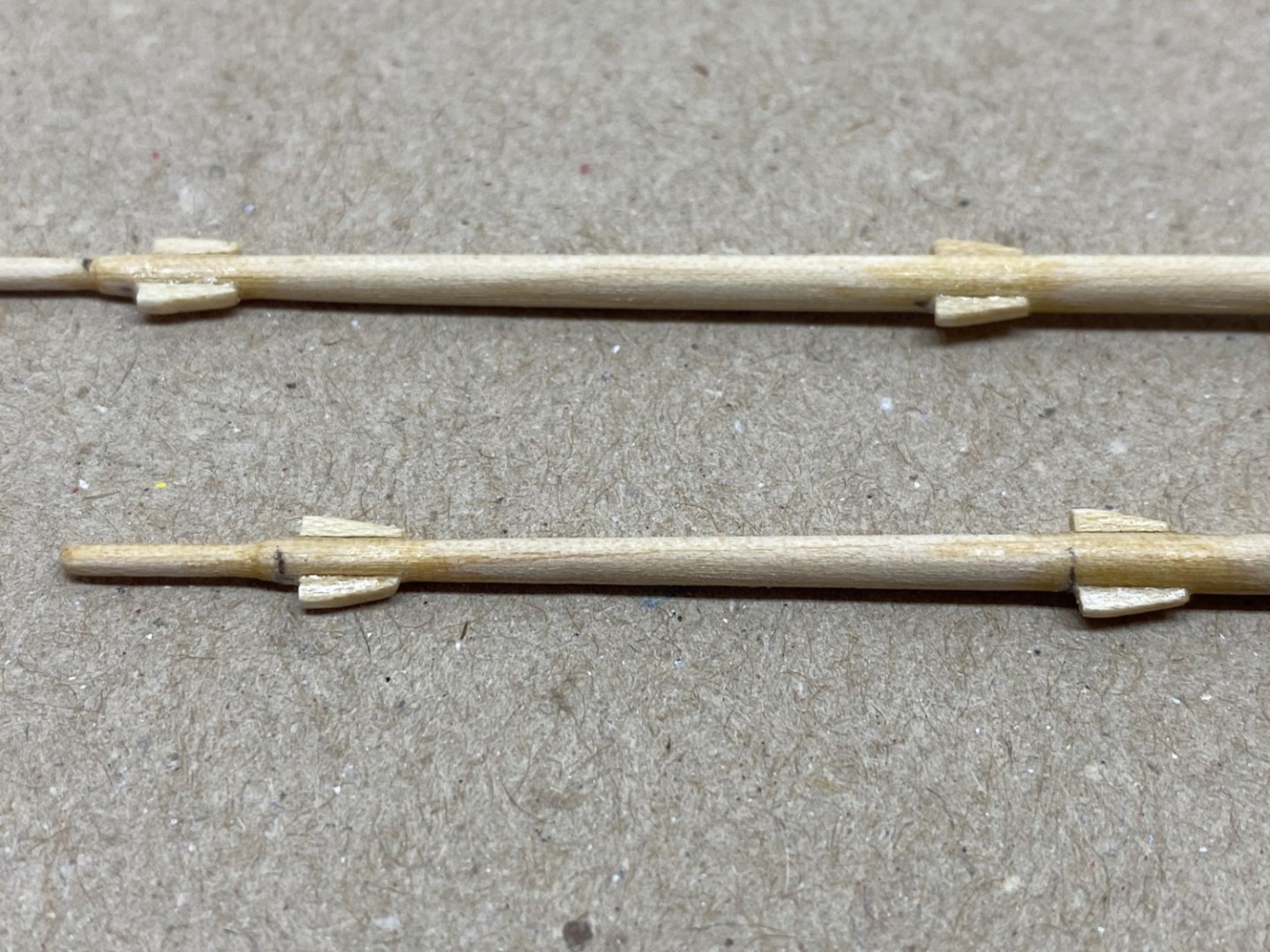
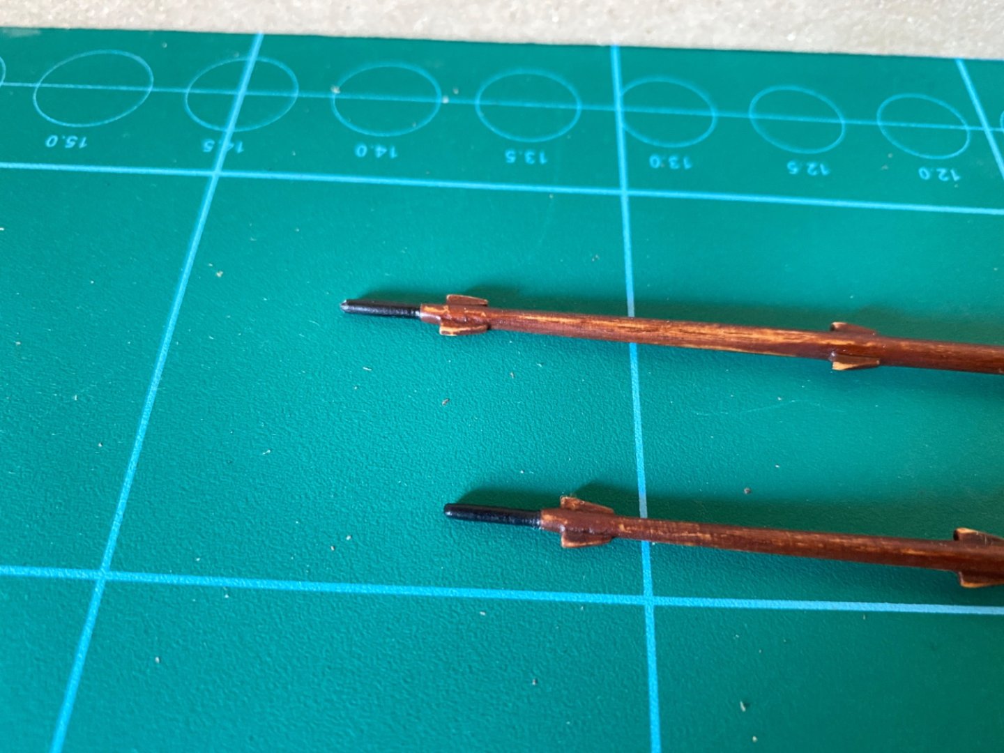
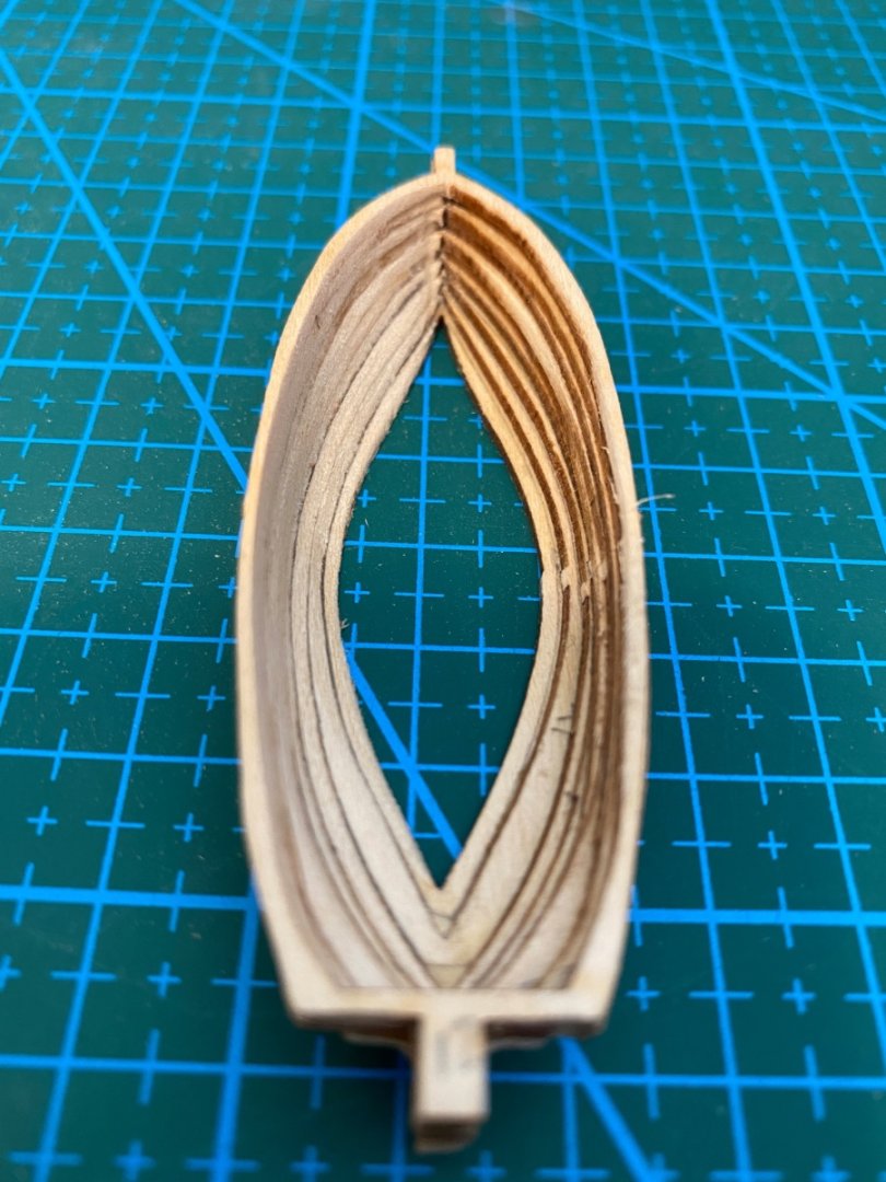
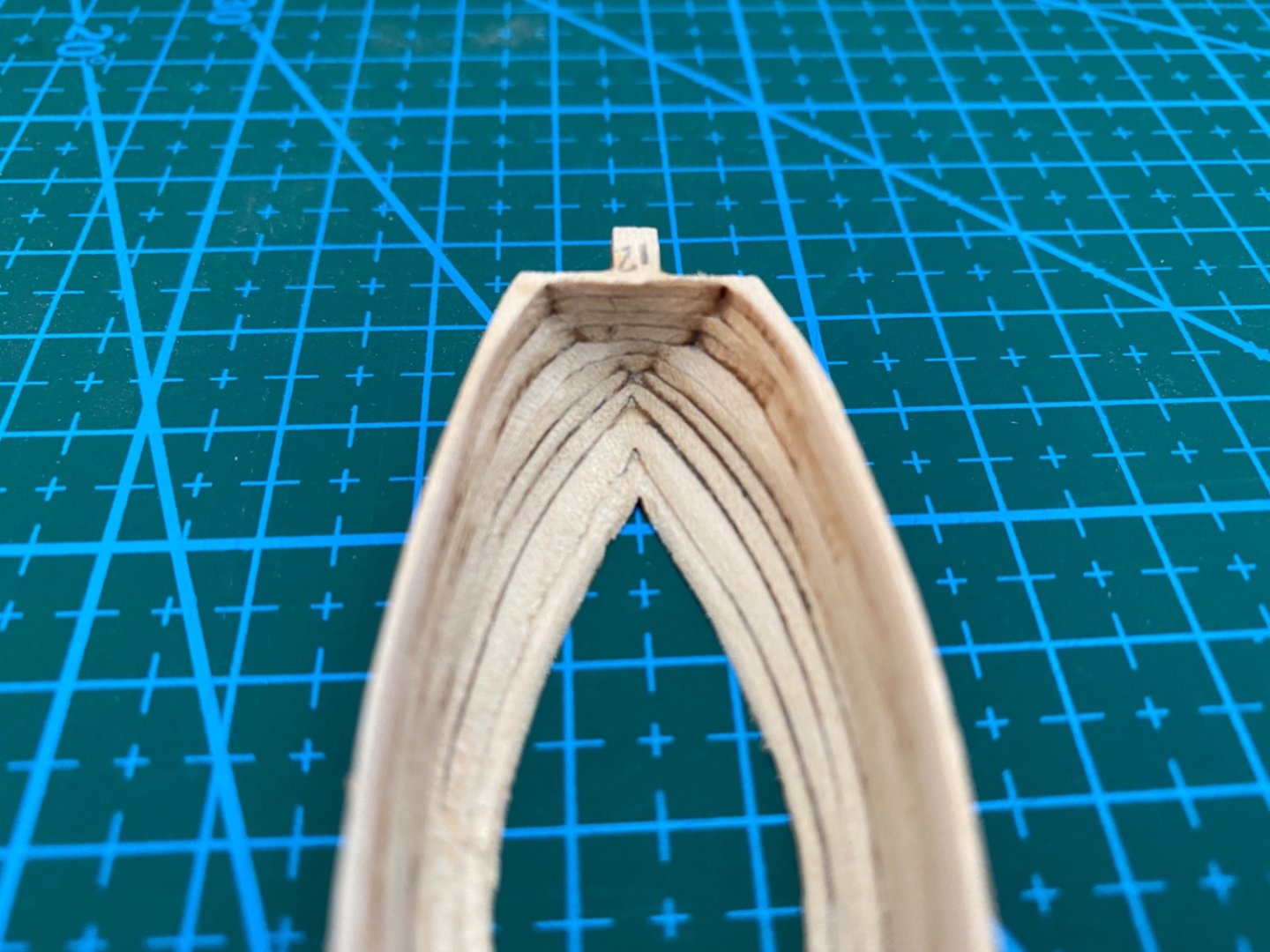
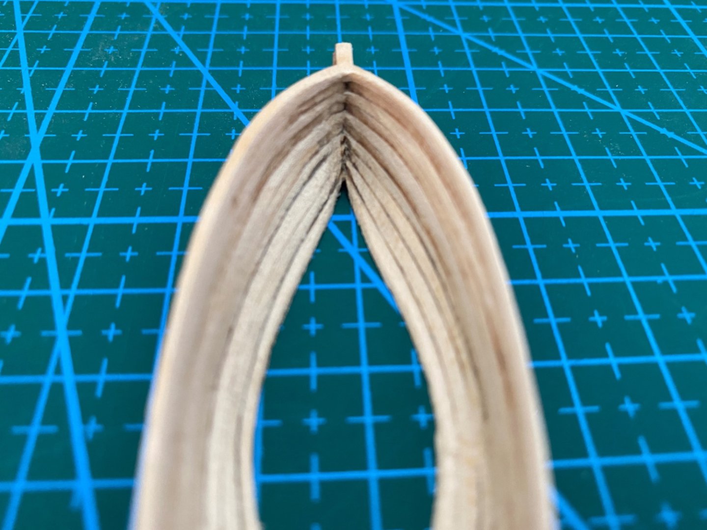
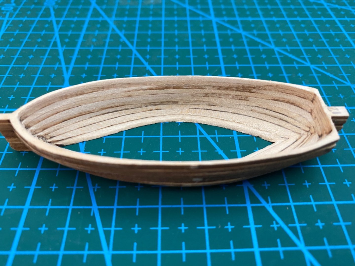
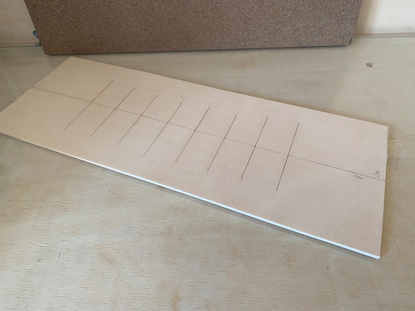
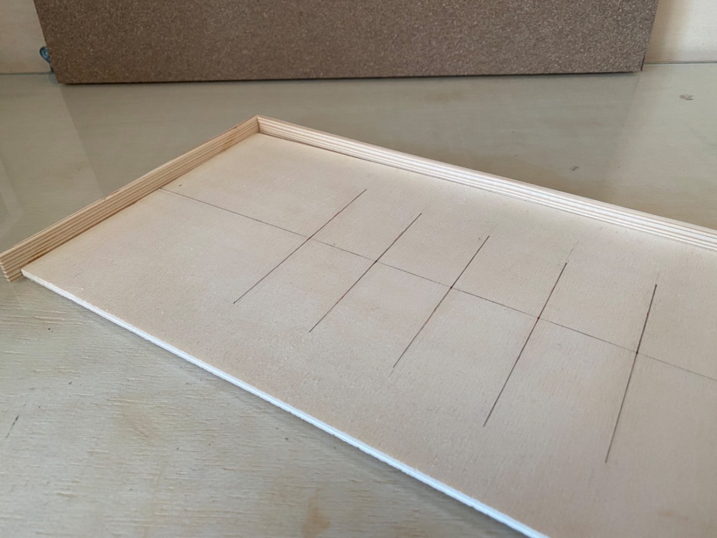
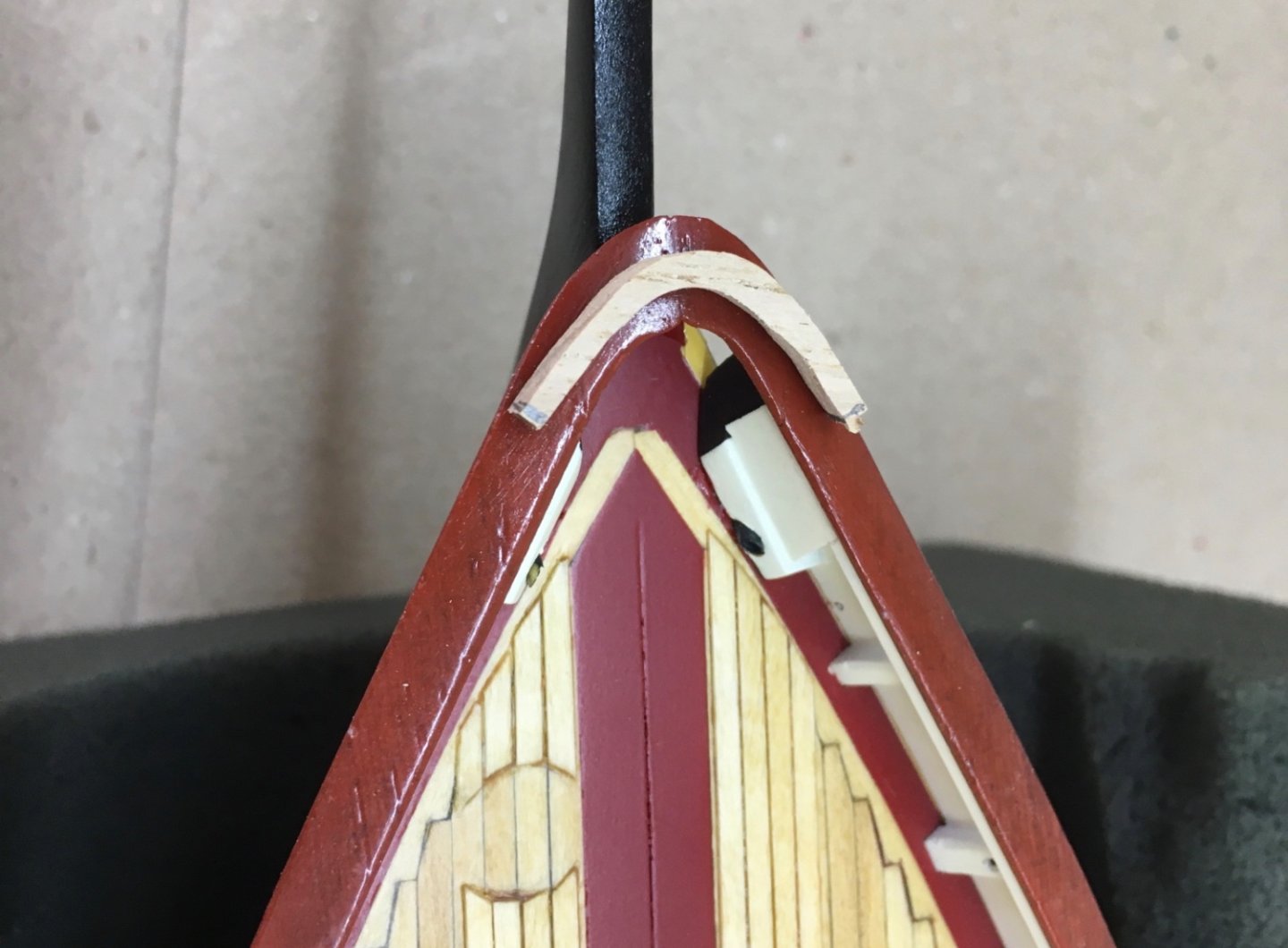
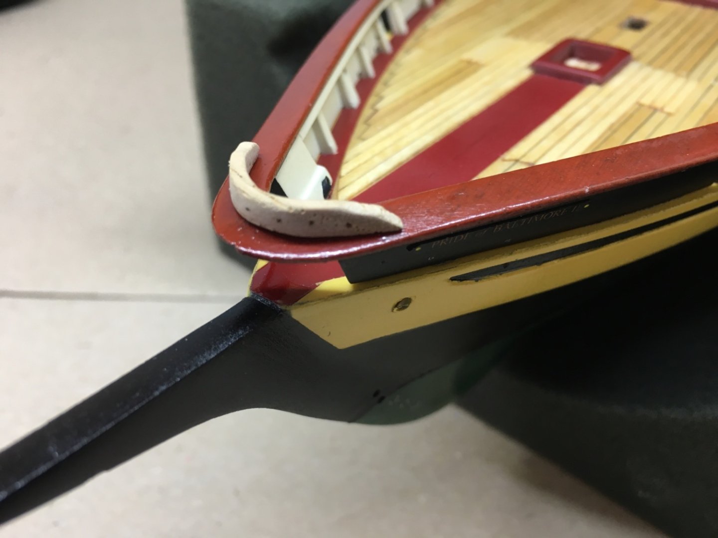
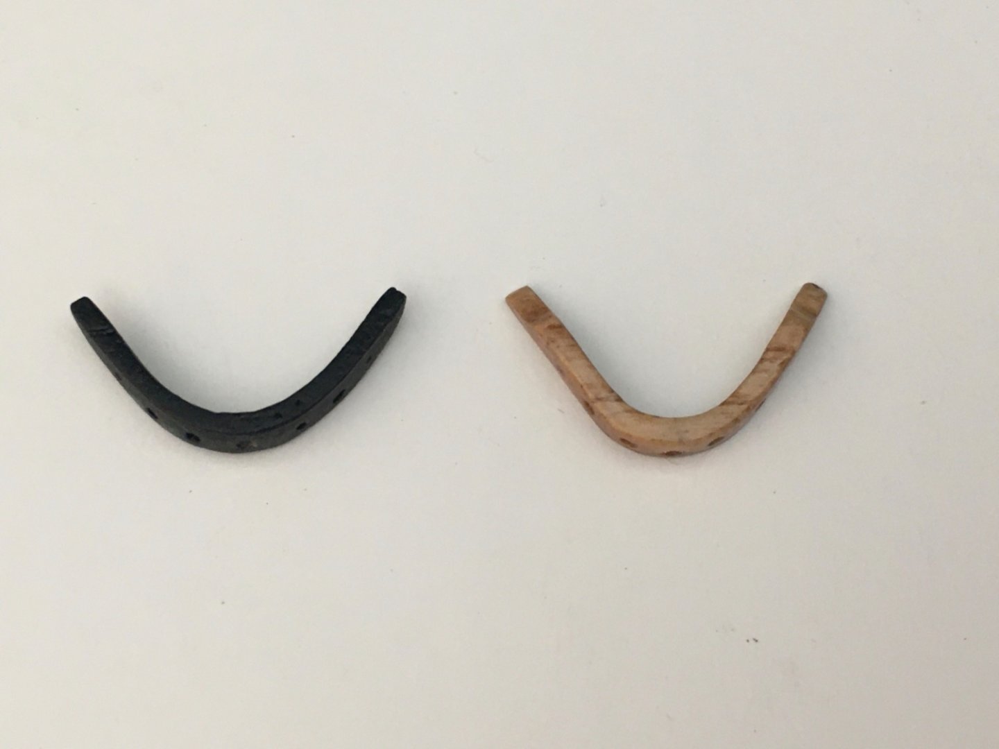
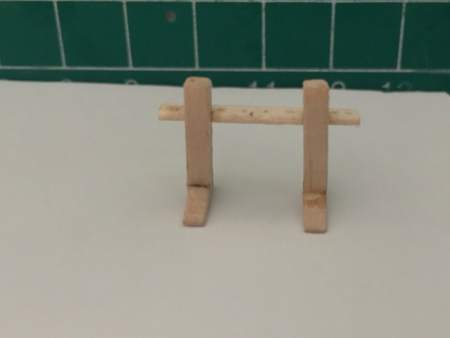
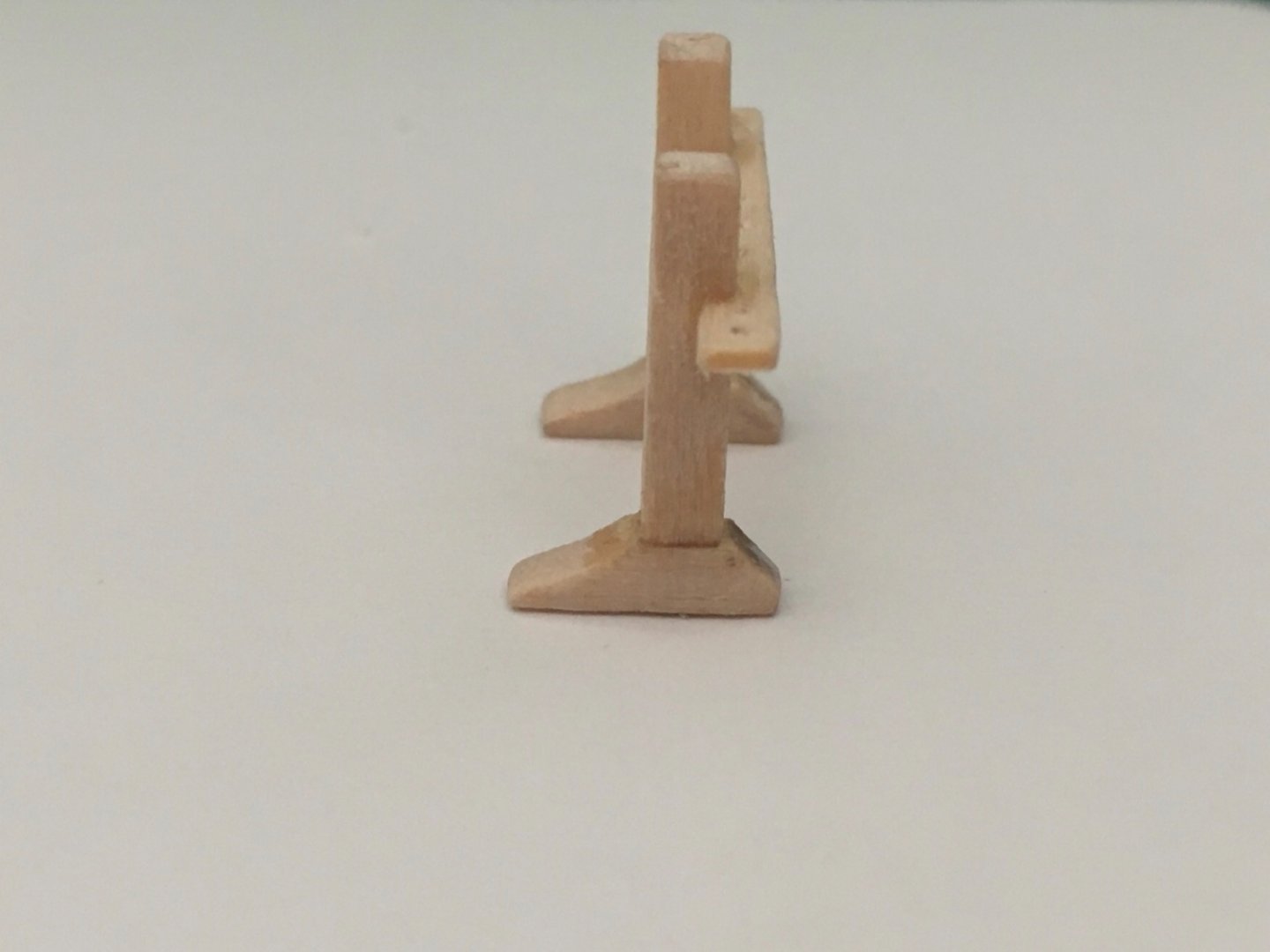
After the construction of the masts and spars , next structure in production line was the bowsprit. Bowsprit was made from 8 x 8 mm ( 5/16 x 5/16 inch) square stock. There were also jibboom, jibboom spreaders and dolphin striker to be made from dowels. Although all the parts of the bowsprit such as port and starboard bees, wood block and iron rings can be made independently , the preparing of the bowsprit itself requires the final position of the windlass or at least samson posts to be set as the aft tip of the bowsprit inserts between the samson posts. Once that location was set, the light cream painted inboard section of the bowsprit was set also. The border between the light cream and black painted sections of the bowsprit (marked with a diagonal line) should align with the bulwark at bow. To make things a little bit more complex, the position of the windlass and samson posts depend on a special part of the deck planks. These planks are inserted in the deck and also present in the main and fore mast insertion areas. These planks are the locations markers for the fife rails . Those three areas are shown with red arrows in the photo of the deck plan. Although these planks must be inserted in and flush with the deck planks, I decided to use 0.4 mm pear strips sanded to 0.2 mm thickness. After their positions were decided and glued , I drilled the holes to receive the nails inserted to the fife rail and windlass systems. Holes for the installment of the bilge pumps and fire hydrant at the main mast base area were also drilled at this time. You can see those special ! planks (red arrows ) , nail inserted fife rail structures and windlass system (small red arrows to visualize the nails) in the photos below. During the final installment of the deck structures you will see better quality of those planks and holes. After the final inboard location of the it was set, bowsprit was prepared by using Proxxon KS 230 and DB 250. All the parts of the bowsprit, jibboom, jib boom spreaders and dolphin striker were prepared. Here is a photo showings them alltogether. Sanding sealer was airbrushed . Grey primer was airbrushed. After the grey primer light cream inboard color was airbrushed. The painted area included a large part of the black section. At this step and before airbrushing black paint , the positions of the metal brackets connecting the bowsprit and stem were set. The bracket system was glued to bowsprit and the holes for the pins to stabilize the brackets system, were drilled on both descending bracket arms and stem. Then the black paint was airbrushed. There was a L shaped metal bracket at the inboard aft tip of the bowsprit. It was prepared from brass sheet . The holes drilled go way down to and include the deck. At the final installment stage nails were inserted through those holes in order to fix the bowsprit to the deck more securely as well as holding the bracket itself. Here you see the stained jibboom placed into position. Although not shown here, the jibboom spreaders and dolphin striker were also painted black at this stage.


- 114 replies
-
- 4
-
-
- Pride of Baltimore II
- Model Shipways
- (and 1 more)
-
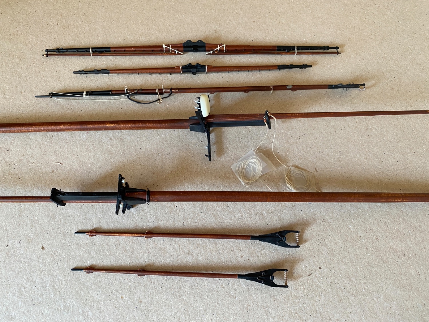
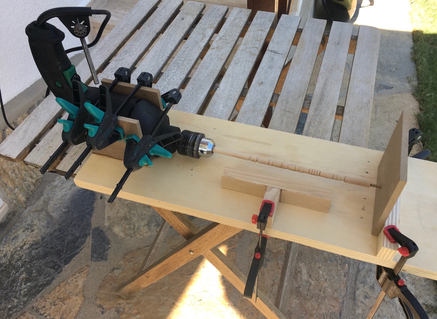
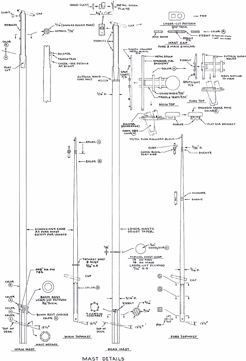
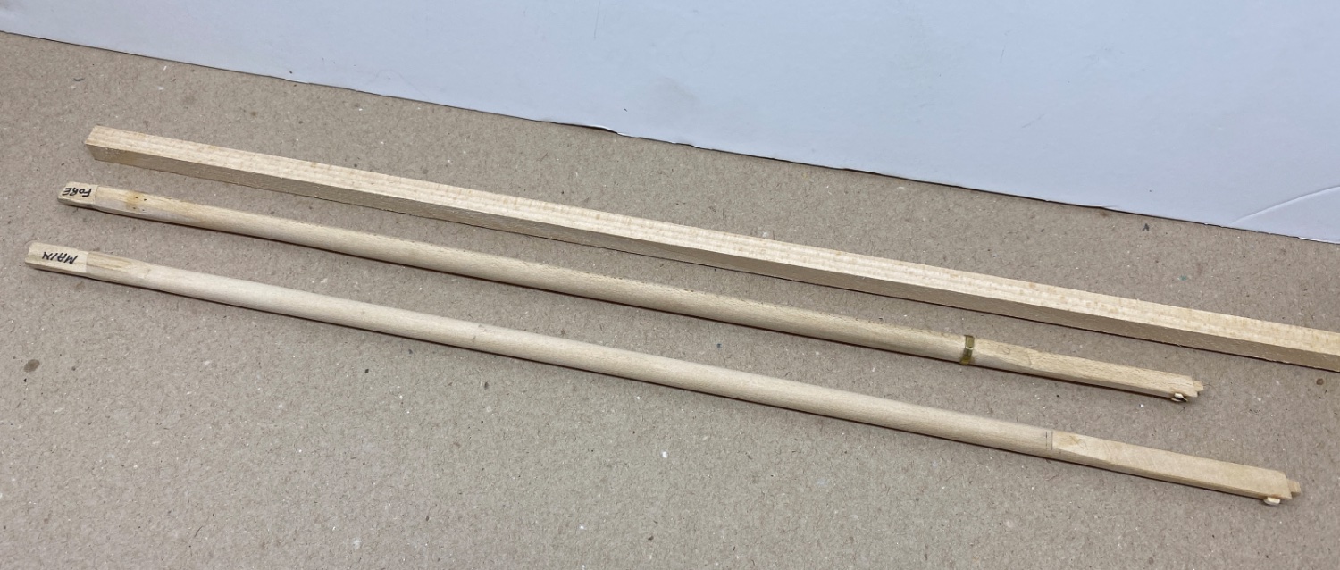
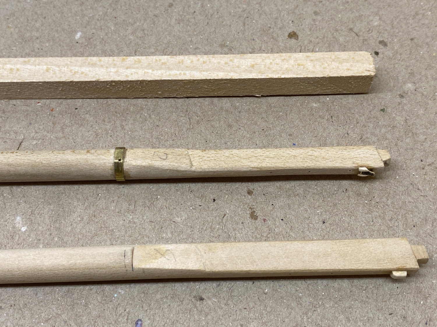
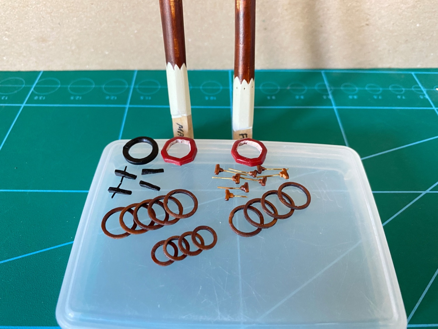
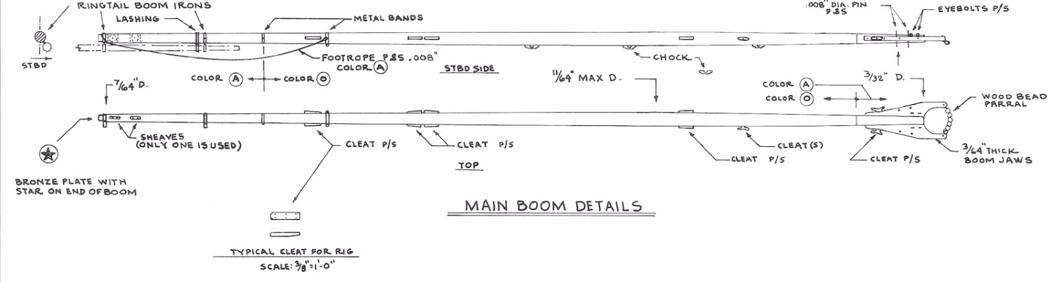
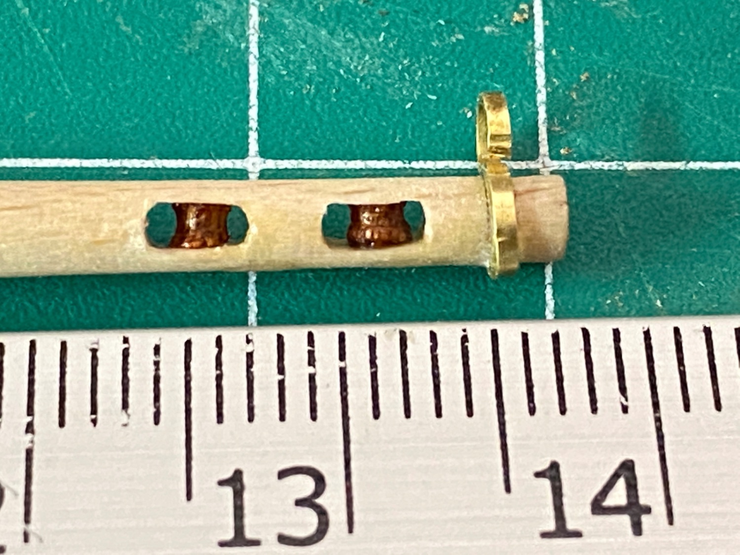
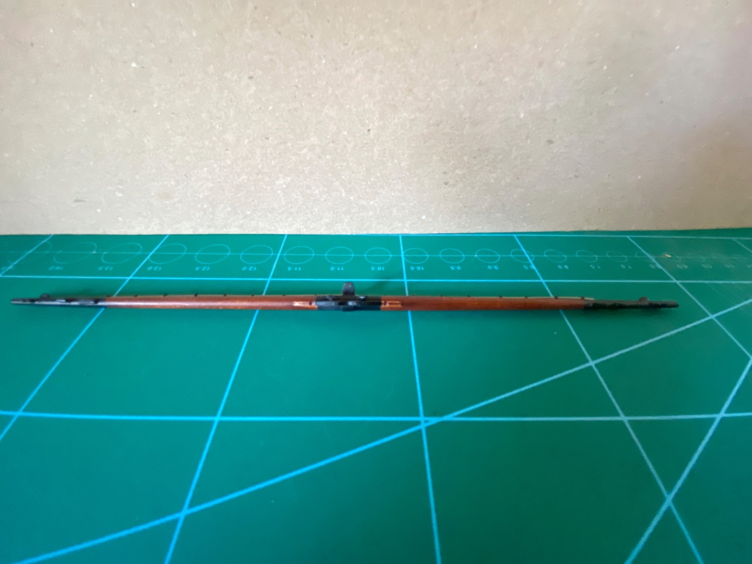
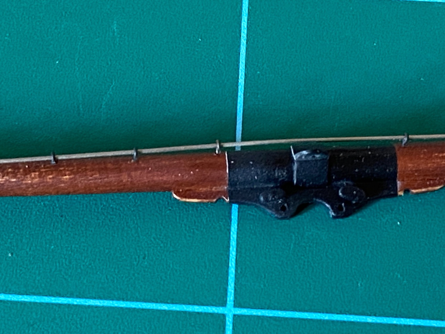
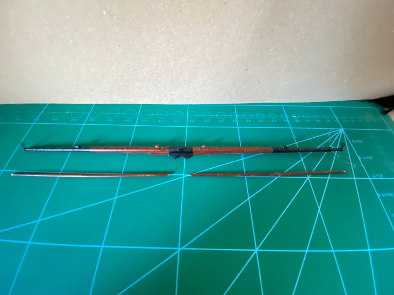
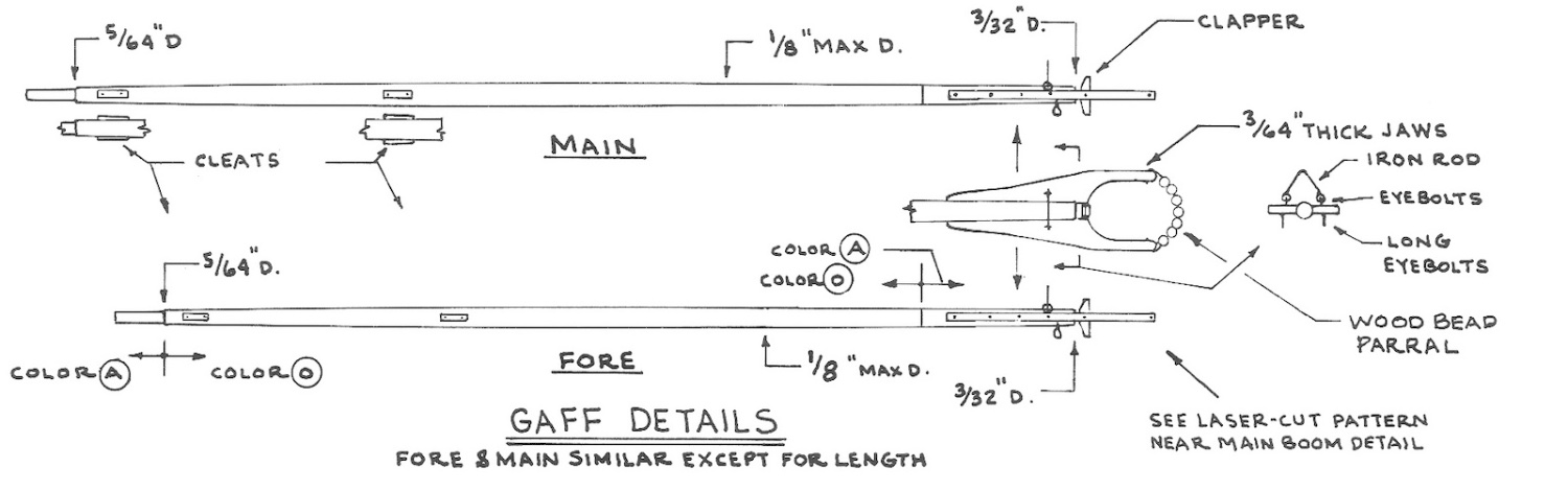
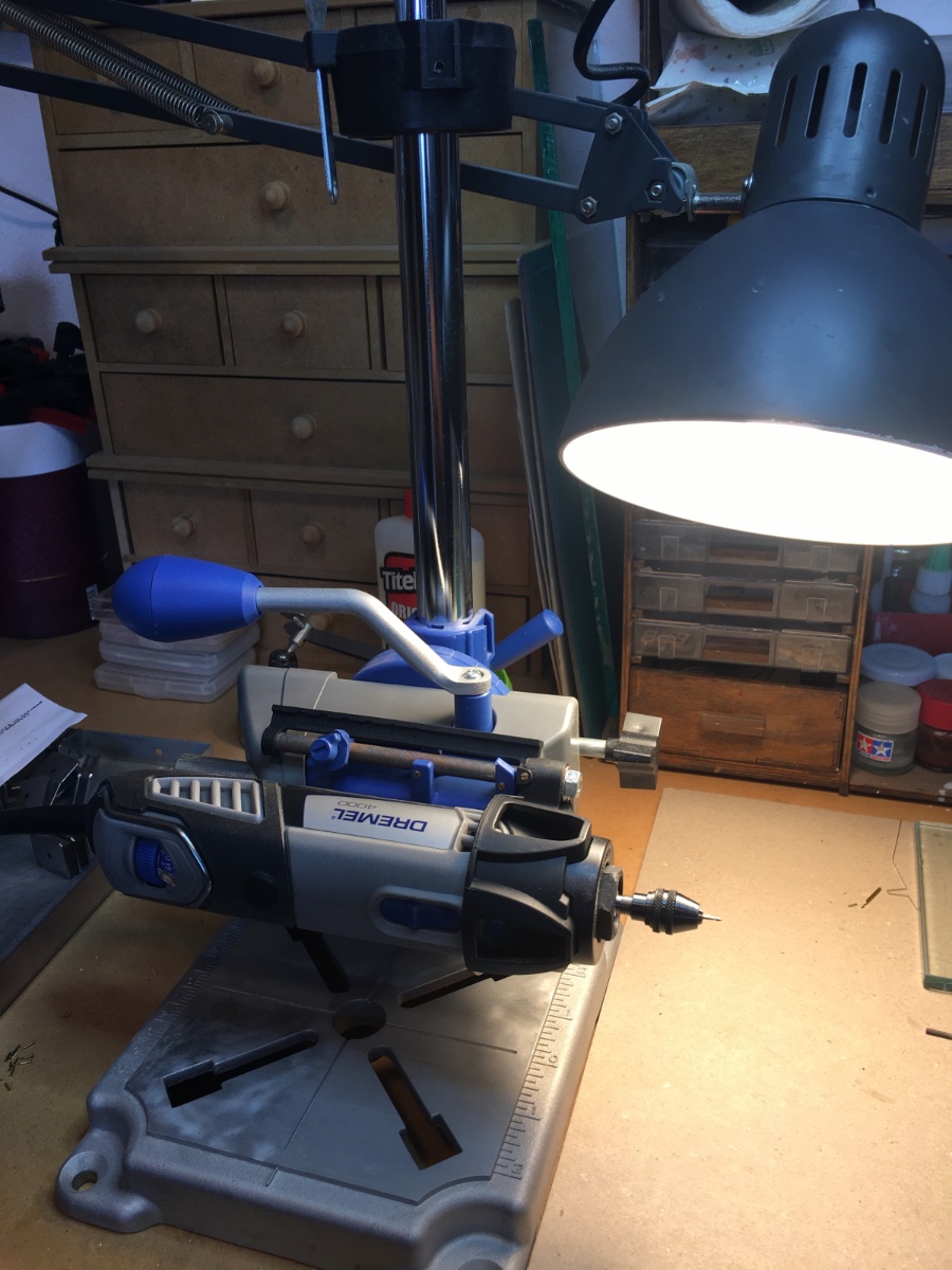
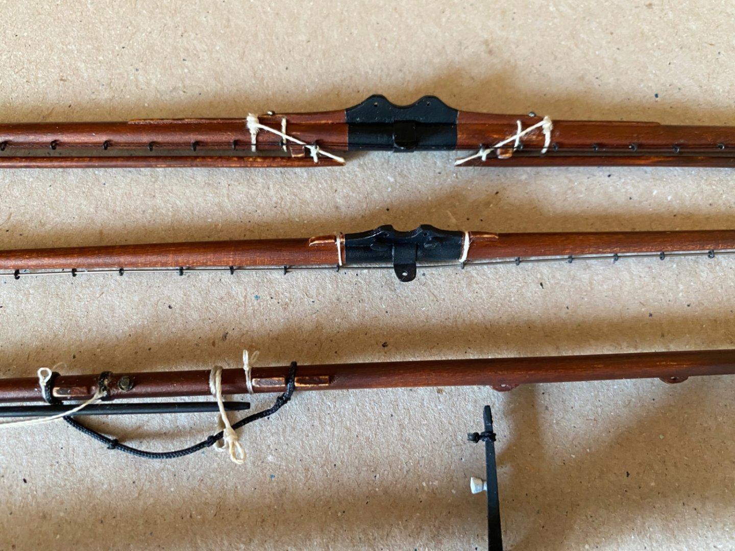
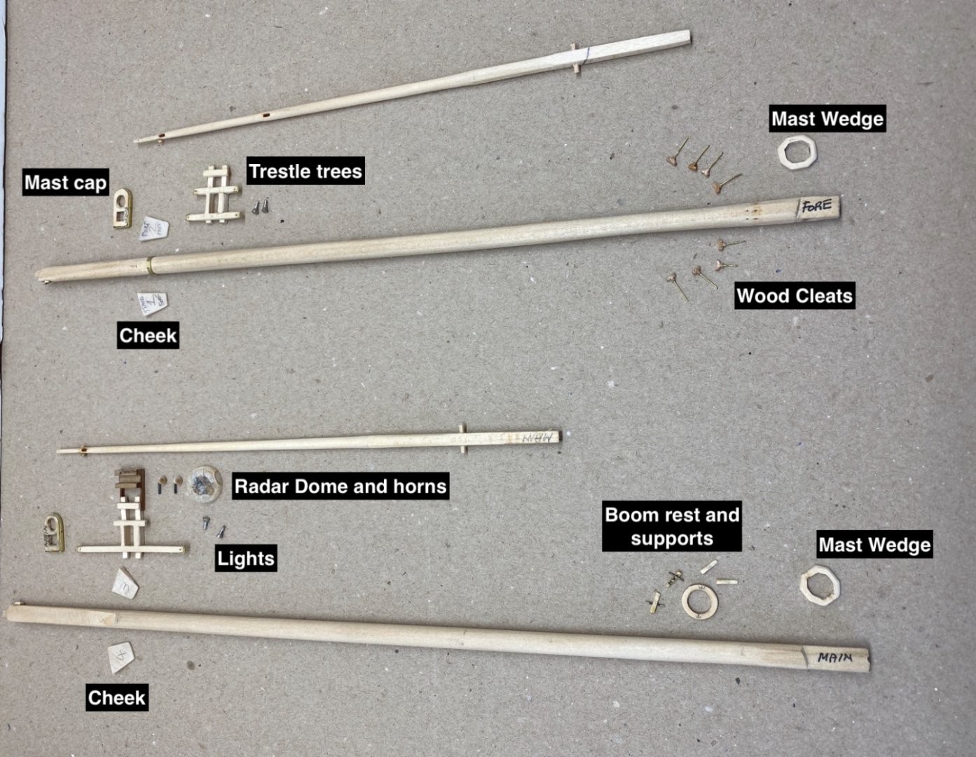
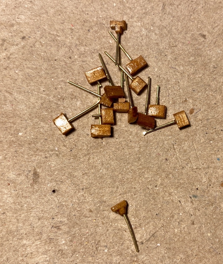
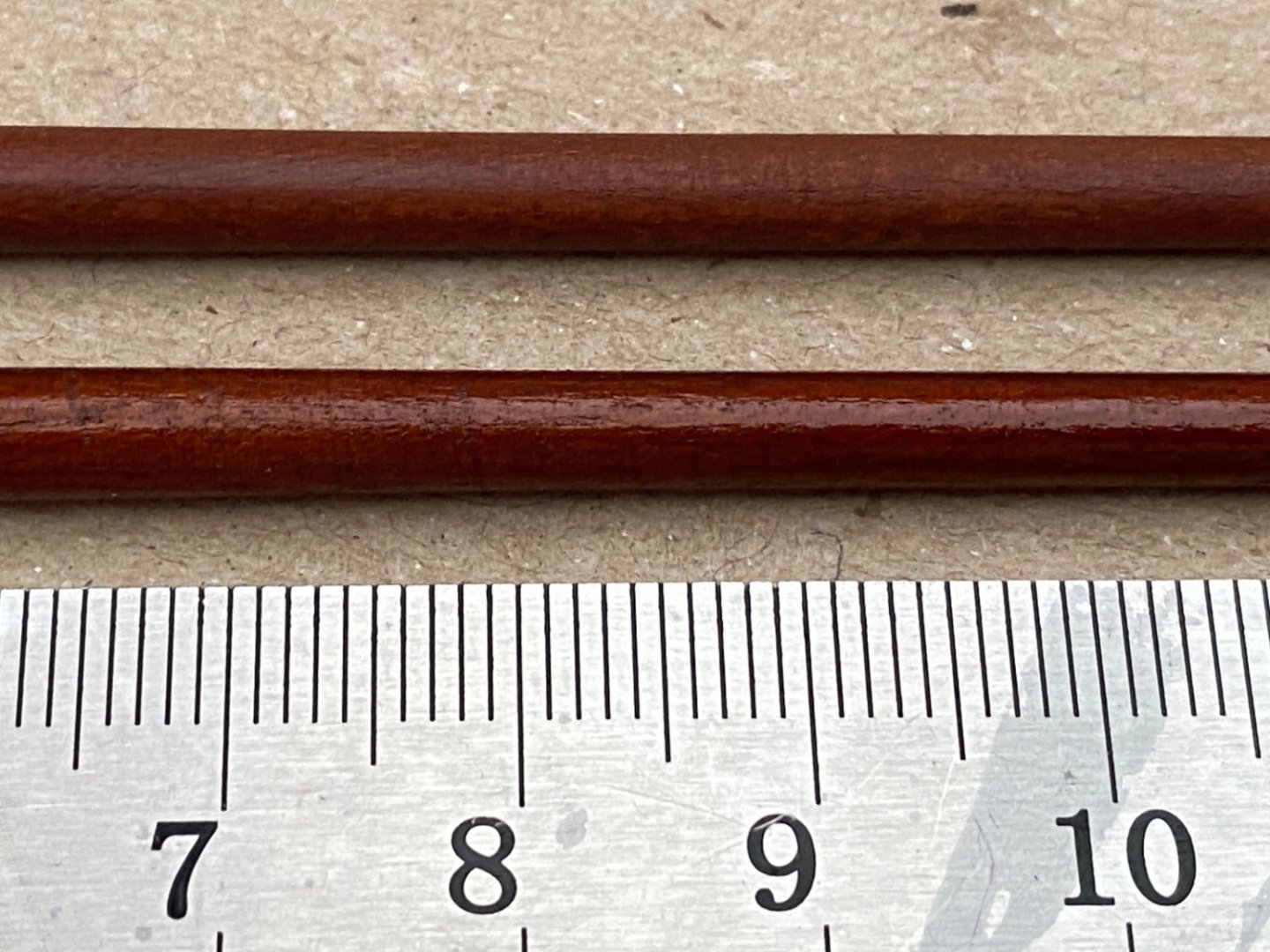
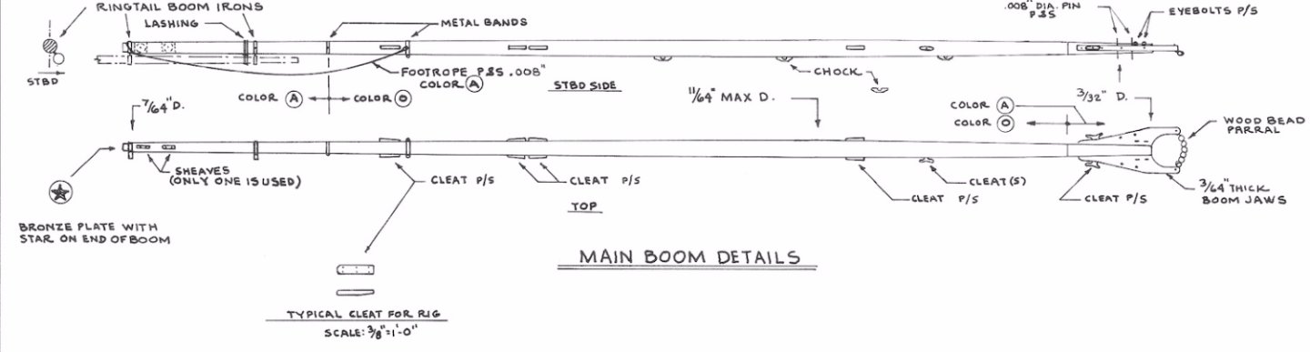
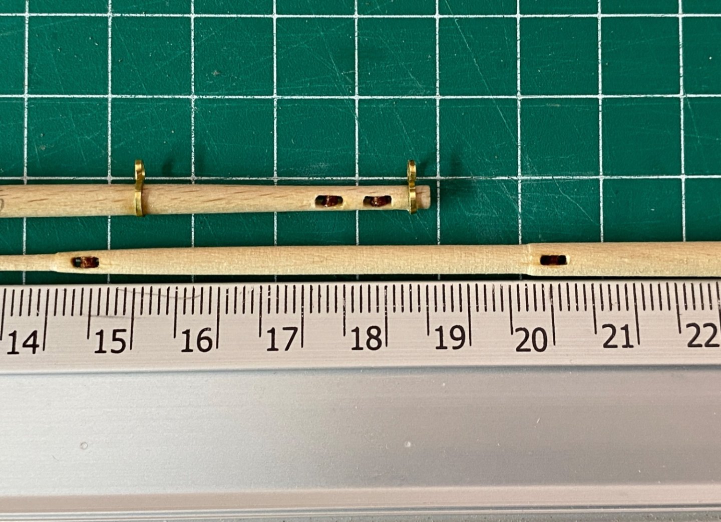
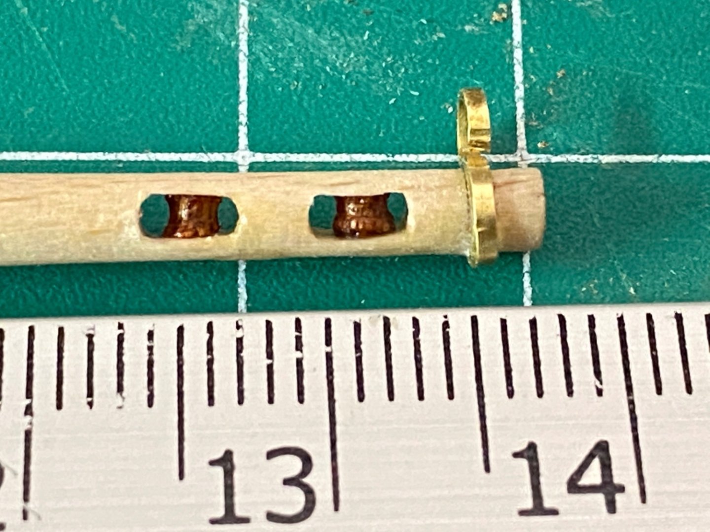
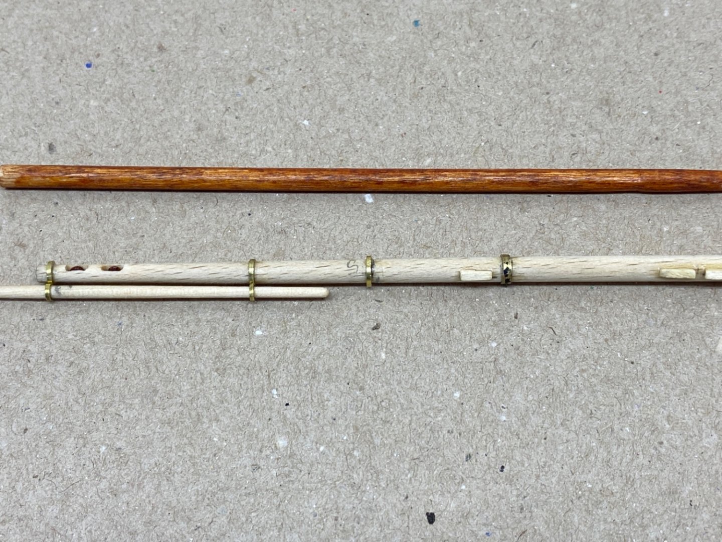
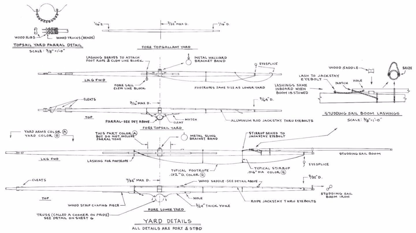
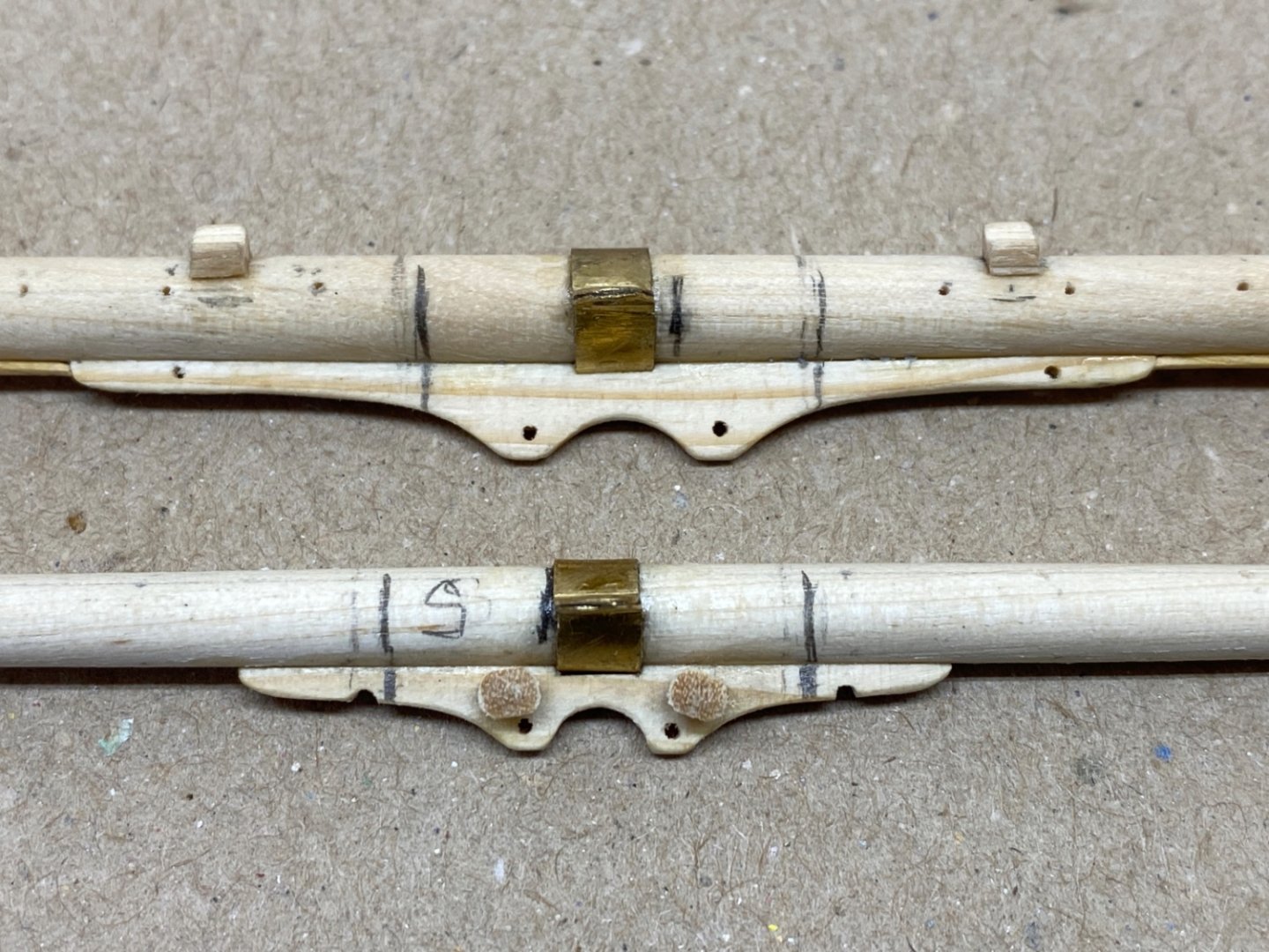
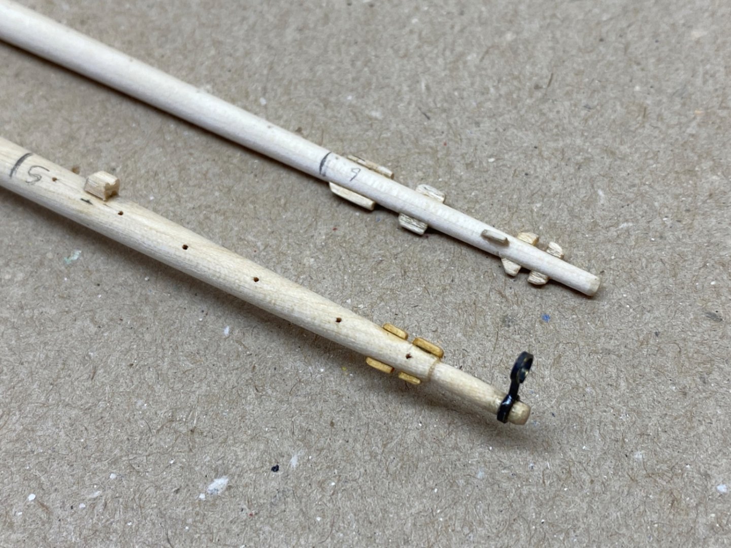
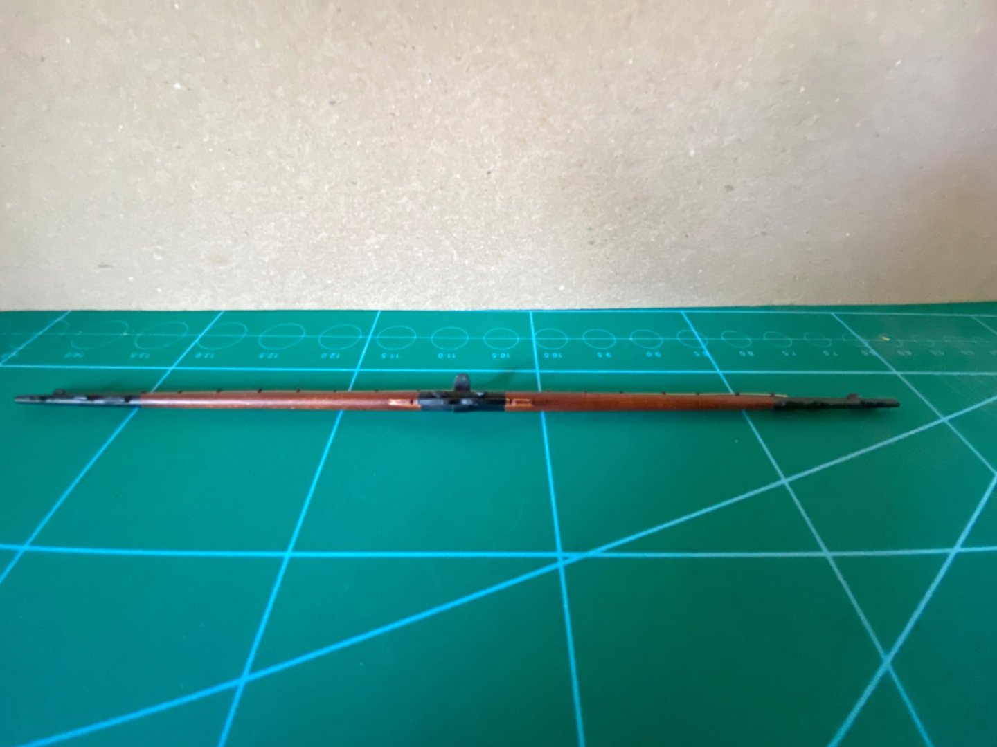
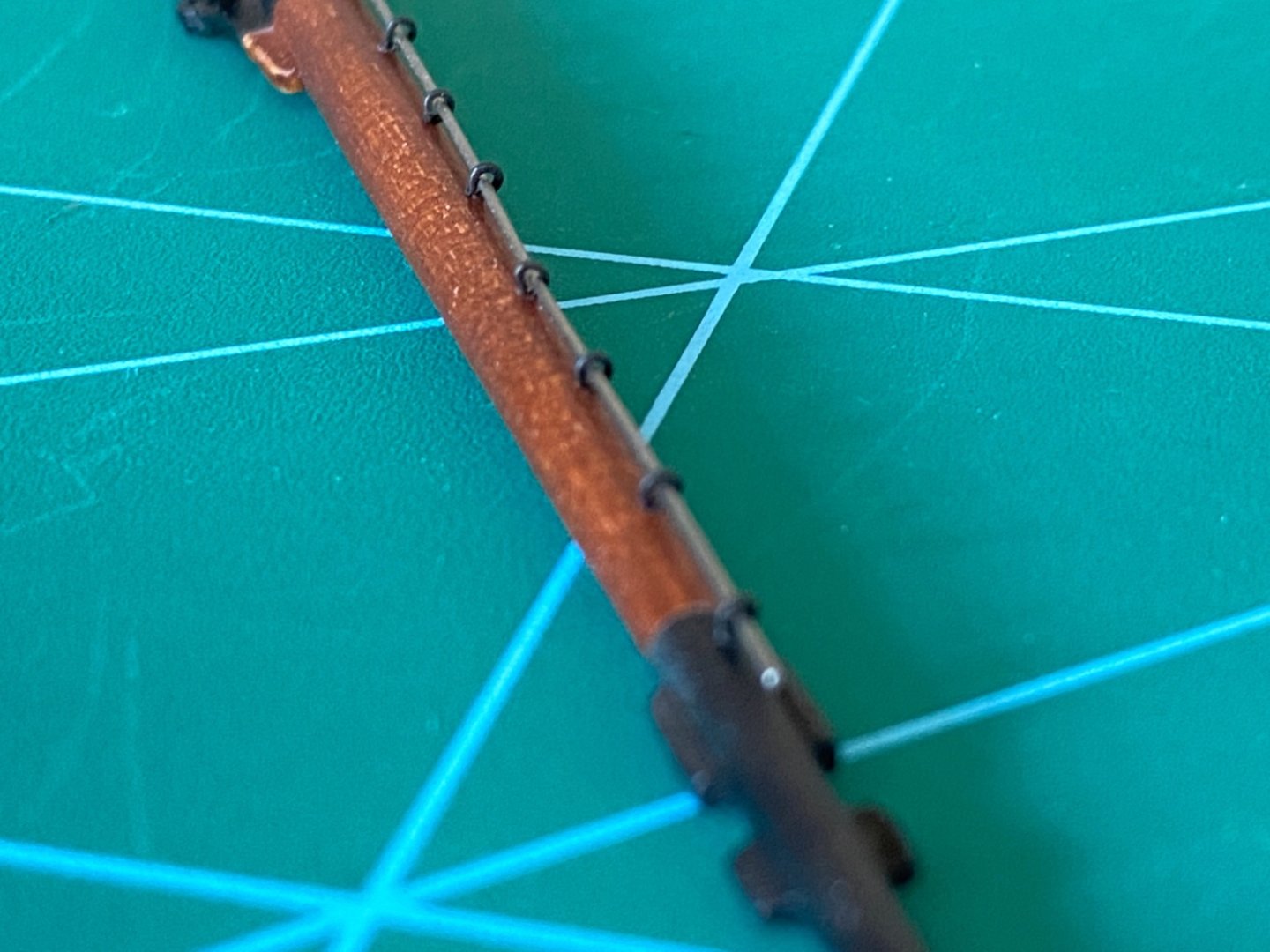
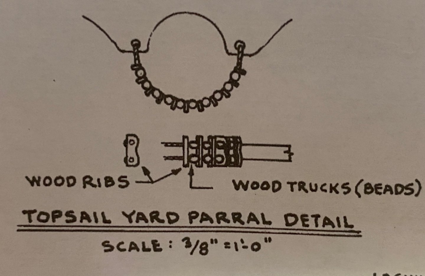
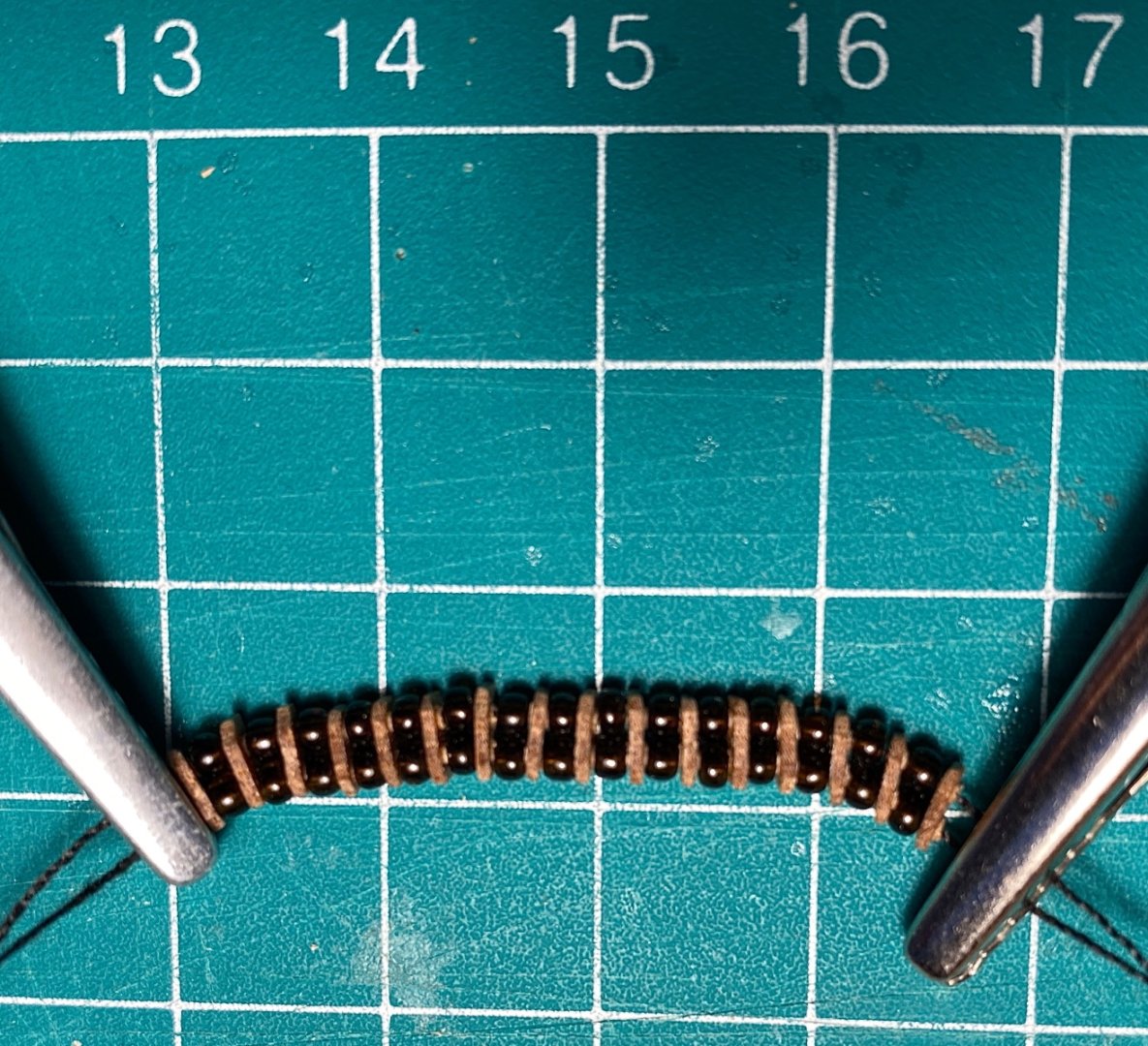
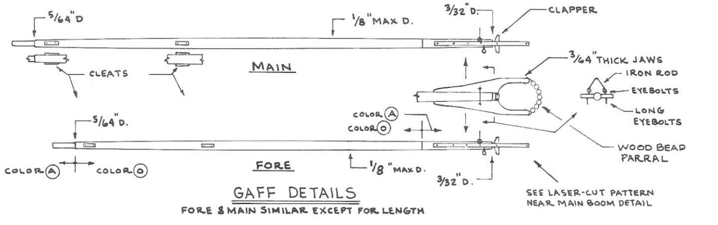
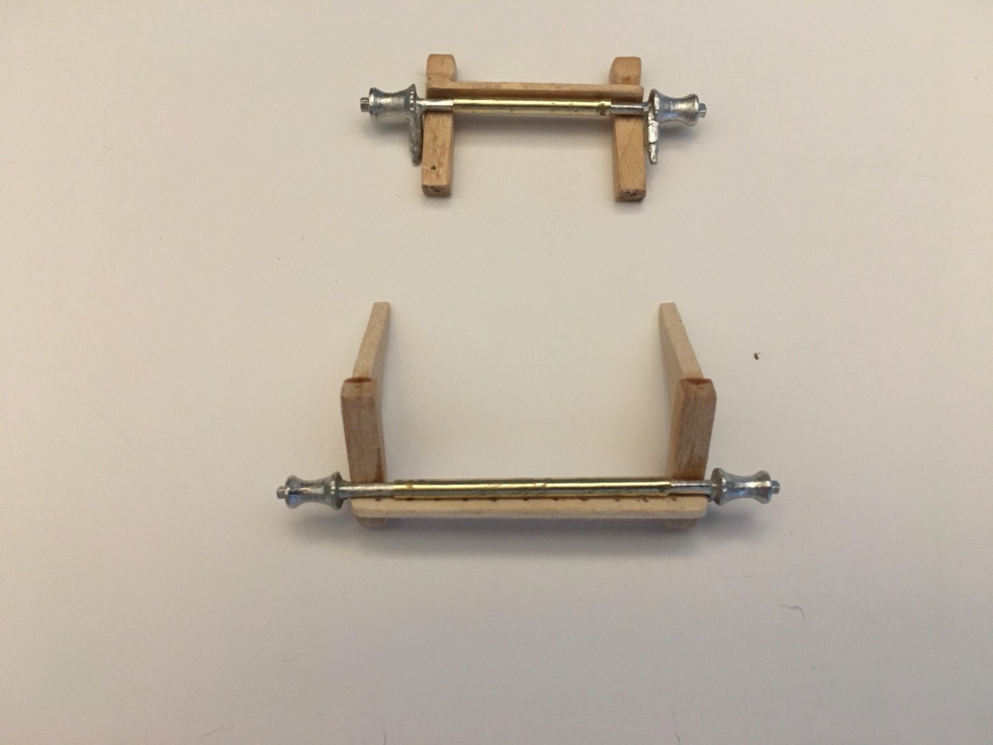
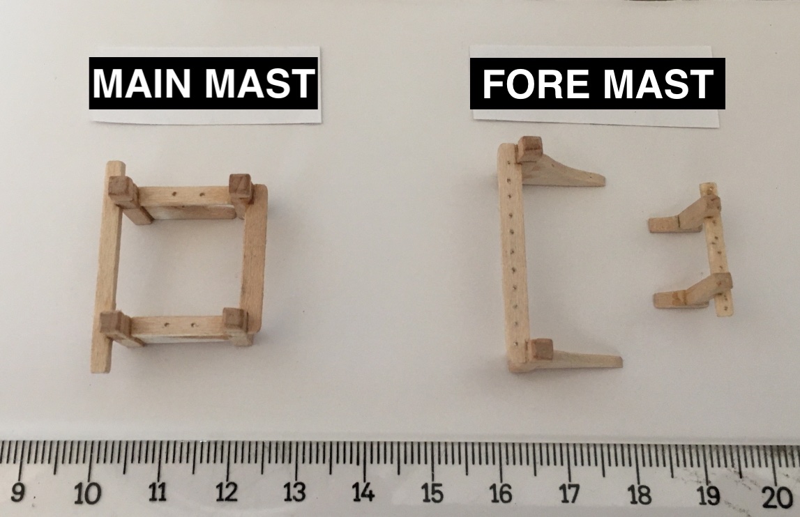
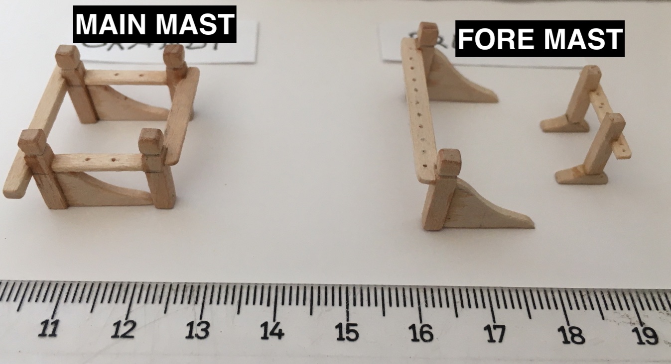
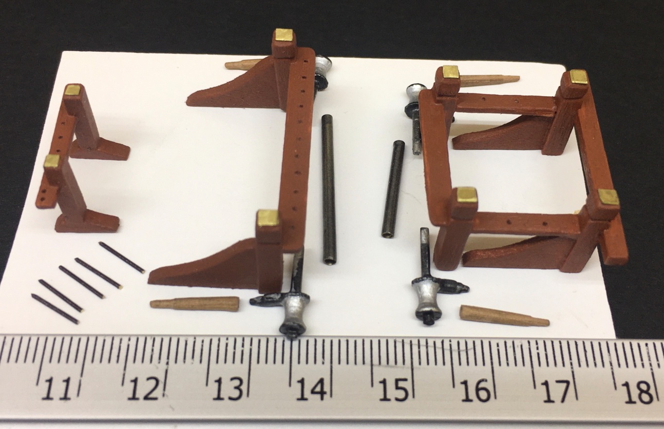
It was April 2022 and 20th month of the real build time. The hull, deck and almost all the structures on the hull and deck were finished and put aside. Now was the time to sail into unknown waters (for me of course) of mast and spar construction followed by thunderstorms of rigging. No matter how much you read or watched videos, when the time comes for the hands-on-job , especially rigging becomes an intimidating step for first timers like me... I decided to start with masts and top masts. Although dowels were given by the kit, I decided to use 8x8 mm (5/16 x 5/16 inch) and 5x5 (3/16 x 3/16 inch ) mm basswood strips for the masts and topmasts respectively . The reason was the octagonal shape of the mast and topmast bases and the special shape of the mast heads. I thought is would be much more easier and precise to use wood strips instead of round dowels. At that time I had already purchased Proxxon DB 250 lathe but the length of 8 x 8 mm strips were overlapping the available work distance in it and the size of the strip did not allow me to insert overlapping part of the strip into the lathe's body. So I created a lathe by using an electrical drill with a chuck allowing pieces of diameter up to 13 mm (approx 8/16 inch). The round parts of the masts were sanded in that DIY lathe. Here is a photo of the DIY lathe with an experimental wood piece. In this DIY lathe and in Proxxon DB 250 when sanding and tapering the topmasts, yards, gaffs and main boom; first I marked the different diameter measurements on the wood I was working on and kept a digital caliper aside for continuous checking the tapering amount. Here is the plan for masts, mast heads and their parts. Here are the photos of the masts with bottom and heads shaped and the body rounded. Both main and fore masts are similar in shape but differ in length. Their round circular parts are not tapered . Bottom parts. The holes on the fore mast are for later cleat insertions. Heads. The one with brass strip band is fore mast. Then the topmasts were prepared. Contrary to the masts , topmasts were tapered towards their head. The hollow spaces for sheaves are prepared. Sheaves were prepared from mahogany dowels turned in lathe. This was done first bi drilling two holes and connecting the holes later. After the sanding of the walls of the space created a sheave was inserted and fixed. The photos of the procedure include the ones done on the main boom. All the details of the main and fore masts were prepared. Here is a close up photo of the wood cleats ( starting and final shapes ) with pins attached and painted with Modelexpo Maple stain. Although the painting of the masts and topmasts were done later with all the other yards, gaffs and main boom, I will now continue with their painted and constructed photos, in order to maintain subject integrity. In all the masts and spars there are black painted areas. All the other parts were stained by Hazelnut color. These areas were brushed lightly to a dull color As seen in the photos of the yards below. Then sanding sealer was applied. Stained areas were masked, Grey primer followed by matt black was airbrushed. Clear matt was the final coat. Here are the photos of the main and fore masts with trestles trees and caps constructed glued. Fore mast on the left and main mast on the right. Cheecks were glued later. Main mast and main topmast connected with special care to maintain the centerline alignment. Radar dome, horns , lights and all the eyebolts placed and glued. When painting the wedge shaped light cream area at the base of the masts , a special cut-to-shape masking was used. Fore mast after painting and combined with topmast. Both masts and topmasts were ready to be installed with all their other parts including mast hoops. They all were put aside and protected until their final installation to the deck. I will continue with main boom. There were many wood and metal structures on the main boom as seen in the photo from the plans. There were metal bands prepared from brass sheets. Different shaped wood cleats and chocks. Brittania metal cleats (three) , eyebolts, pins, laser cut boom jaws and wood bead partials ( for which instead I used smallest size jewelry beads ). All those structures were carefully manufactured and glued. The sheaves and ringtail boom irons at the aft end of the boom (top of the picture). The main boom before painting. After painting Then yards were made. The yards have a lot of structures on the when compared to masts and main boom. Here are photos of their construction and painting steps. Topsail yard a special parlak made from wood ribs and beads. Although I tried to prepare the piece seen in the photo below, later I only the one row of the beads as the prepared one was way out of scale ! The last spars to be constructed were the main and fore gaffs. These also had wood cleats, eyebolts and special shaped iron rods. Gaff production steps All the spars were kept in a closed space for protection until final installment, just like the masts. Topsail yard was also prepared and stained. However in will be placed on the aft port bulwarks. Studding sail booms were integrated to their stowed positions on Fore lower yard just like ringtail sail boom on main boom. Ringtail sail yard and Studding sail yards were not made as they were kept below deck most of the time.


- 114 replies
-
- 5
-
-
-
- Pride of Baltimore II
- Model Shipways
- (and 1 more)
-
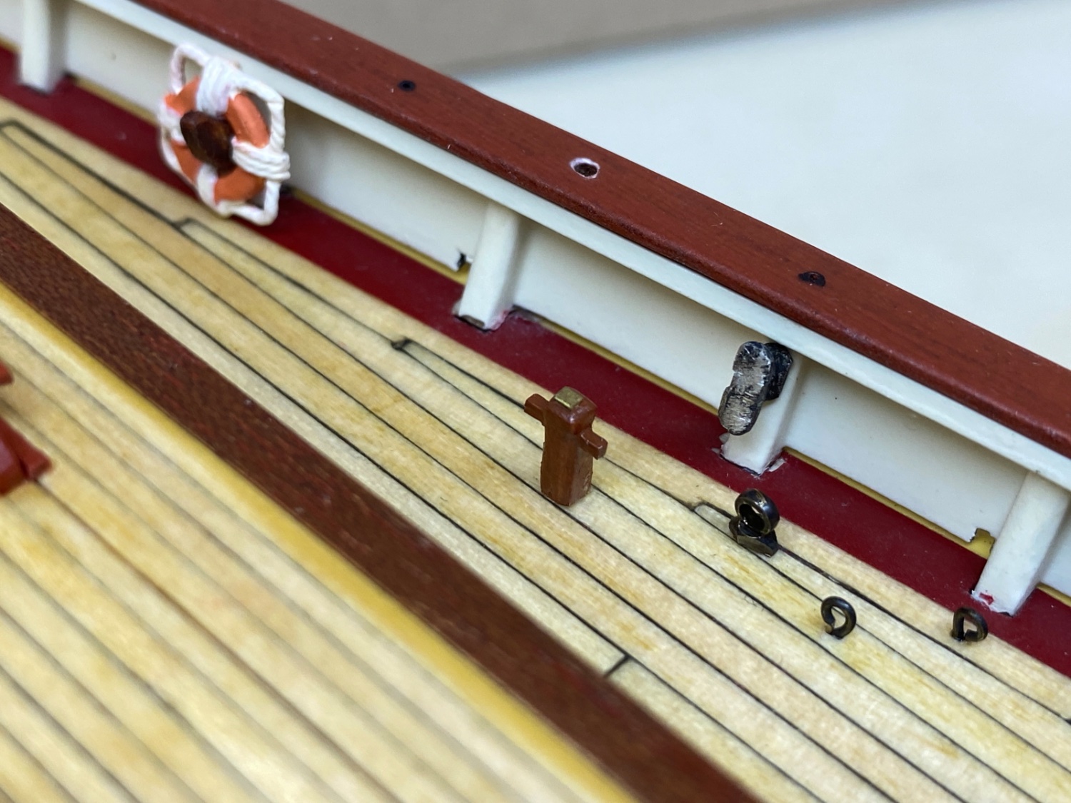
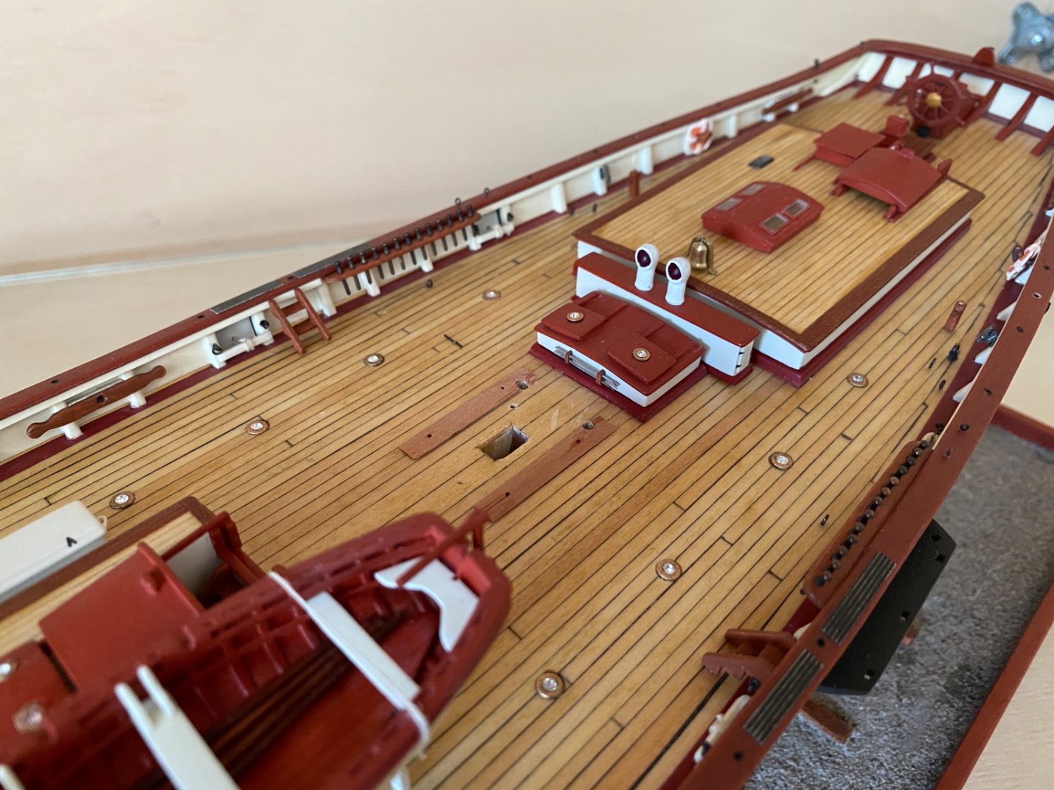
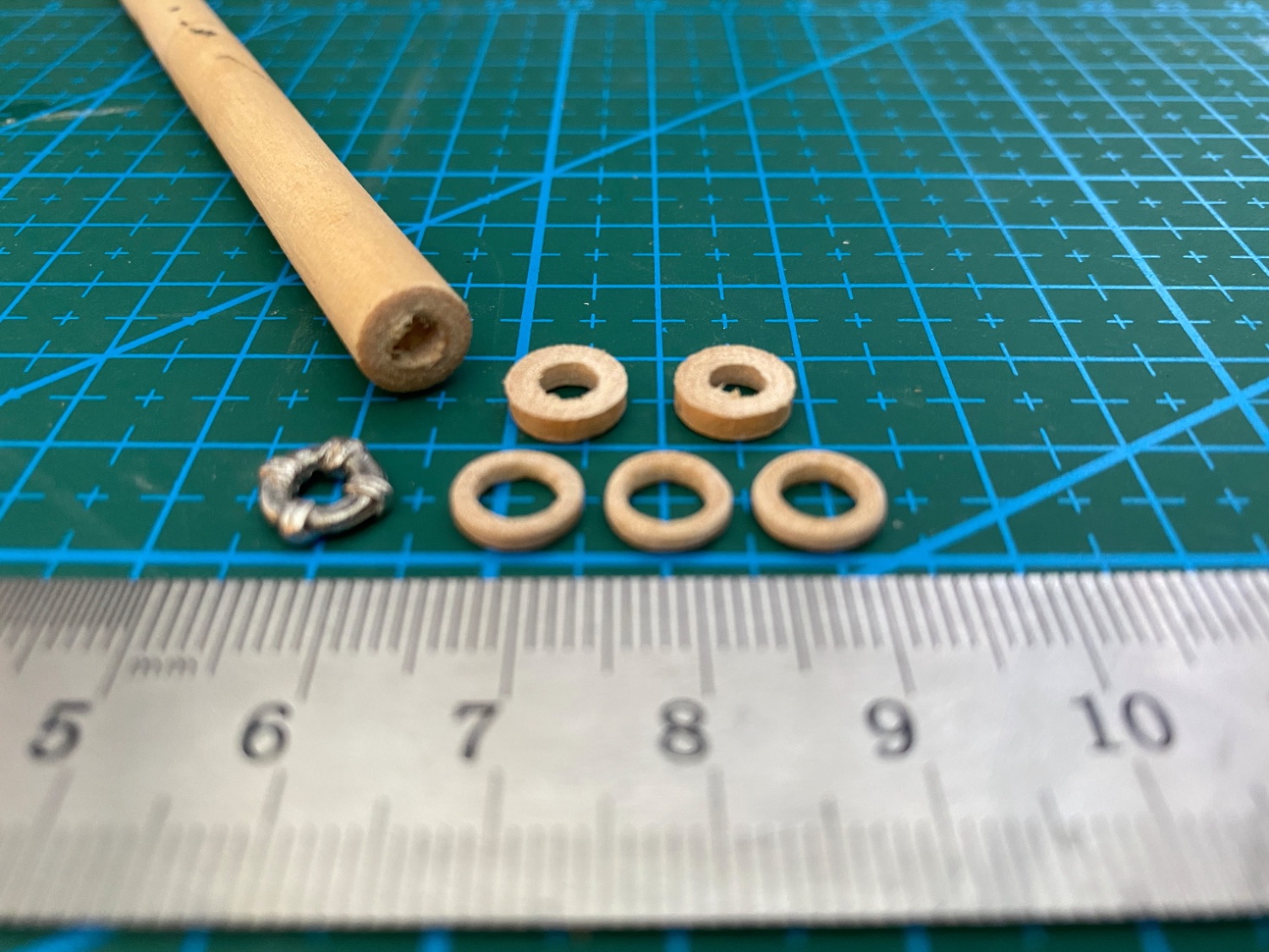
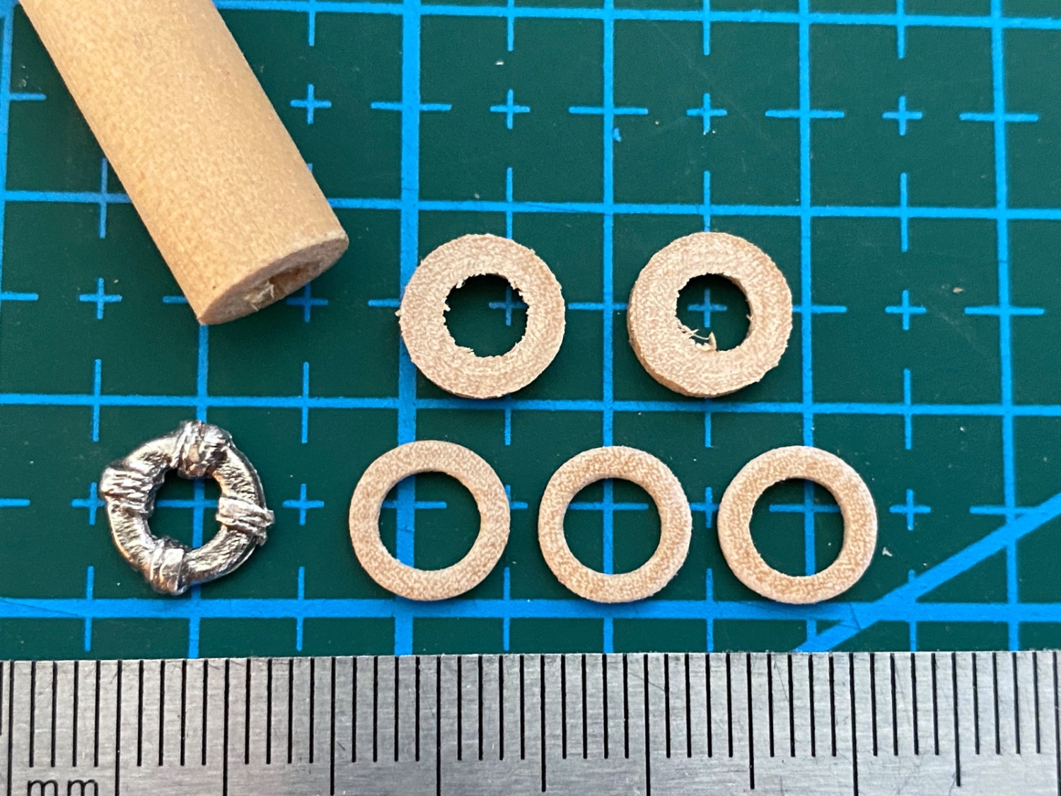
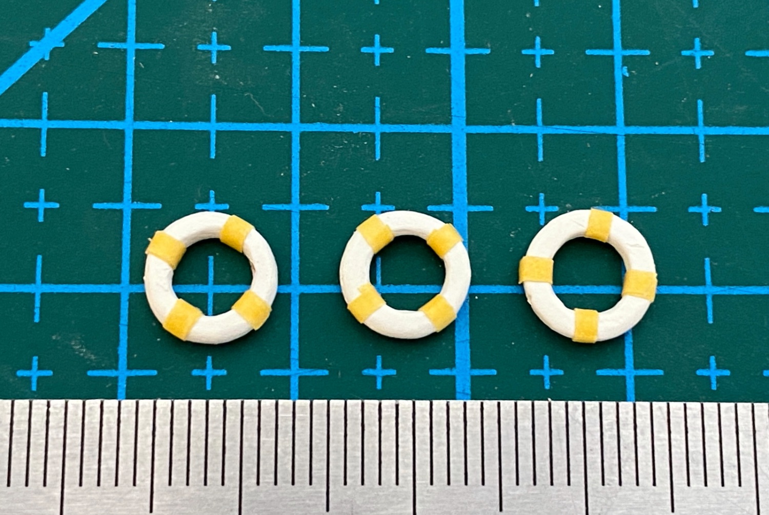
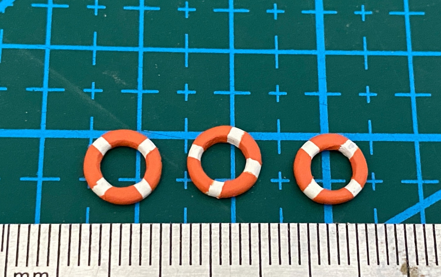
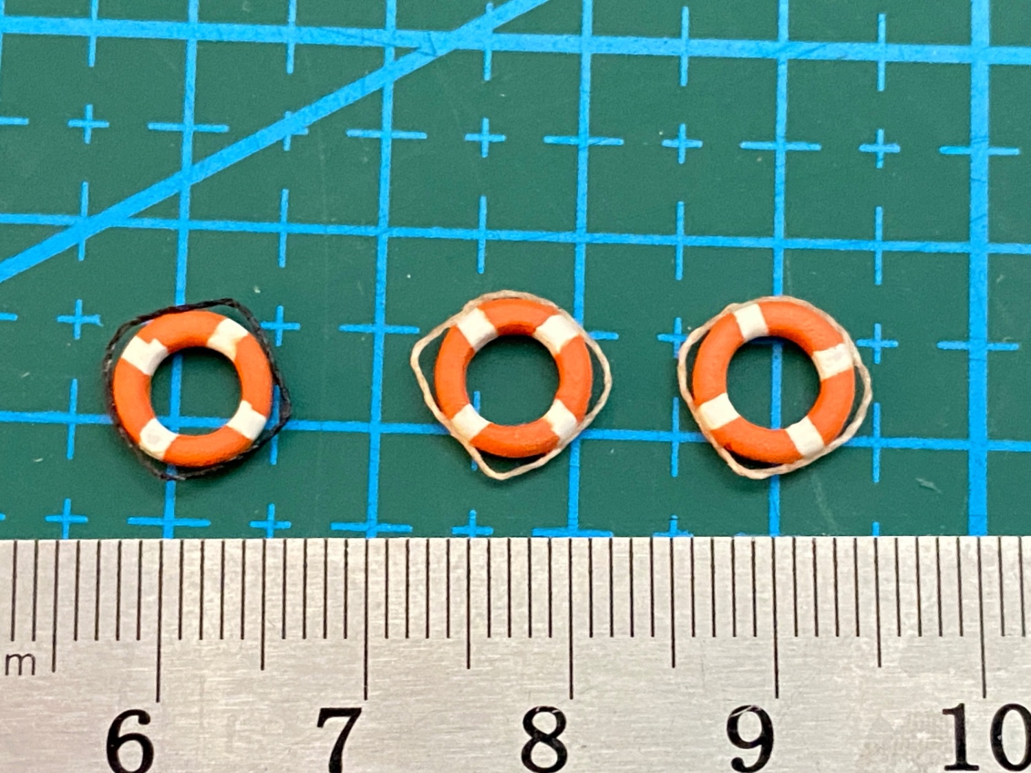
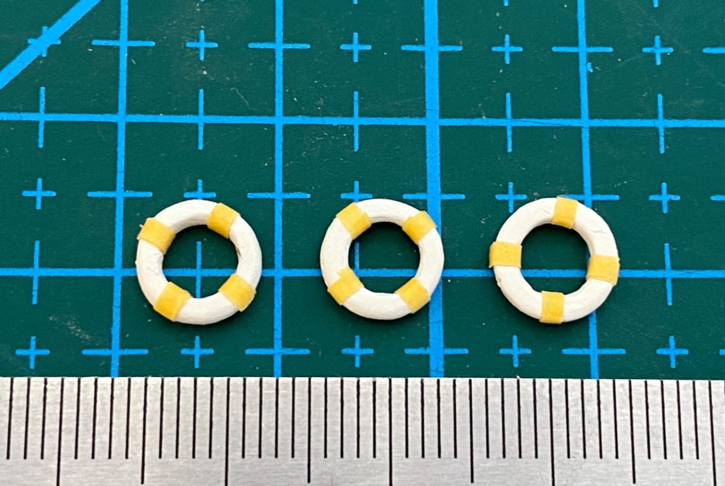
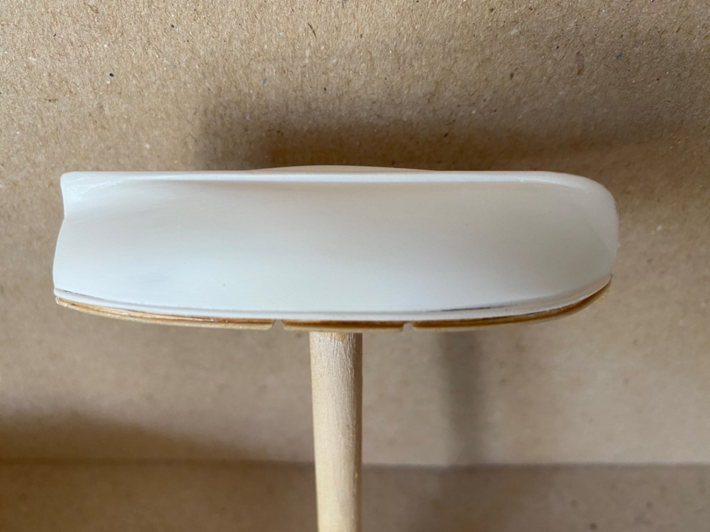
Life rings given by the kit . I was unable to use airbrush properly and was forced to brush paint them. The result you see in the photo below taken during the dry fitting of the deck structures somewhat did not satisfy me. So I decided to manufacture them from scratch . I used a dowel with the same diameter as the kit's life rings and prepared wood rings by turning it on Proxxon DB 250 (which was purchased at that time) .After sanding them to shape and applying sanding sealer I primed them Tamiya white. Tamiya XF-1 white was applied first . Then after masking the 4 white band areas Tamiya Orange (A mixture from a previous project) was airbrushed. The final clear matt coat finished the painting job. Then tan thread was added on two and black thread to the third as ropes around them. The result was way more satisfactory than the kit's according to me.


- 114 replies
-
- 3
-
-
- Pride of Baltimore II
- Model Shipways
- (and 1 more)
-
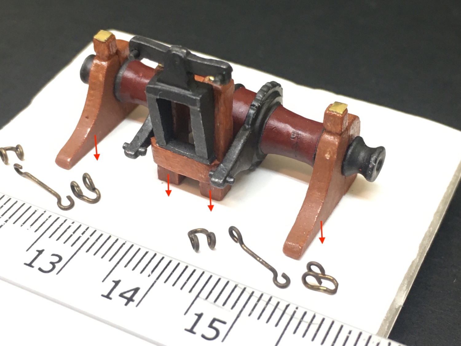
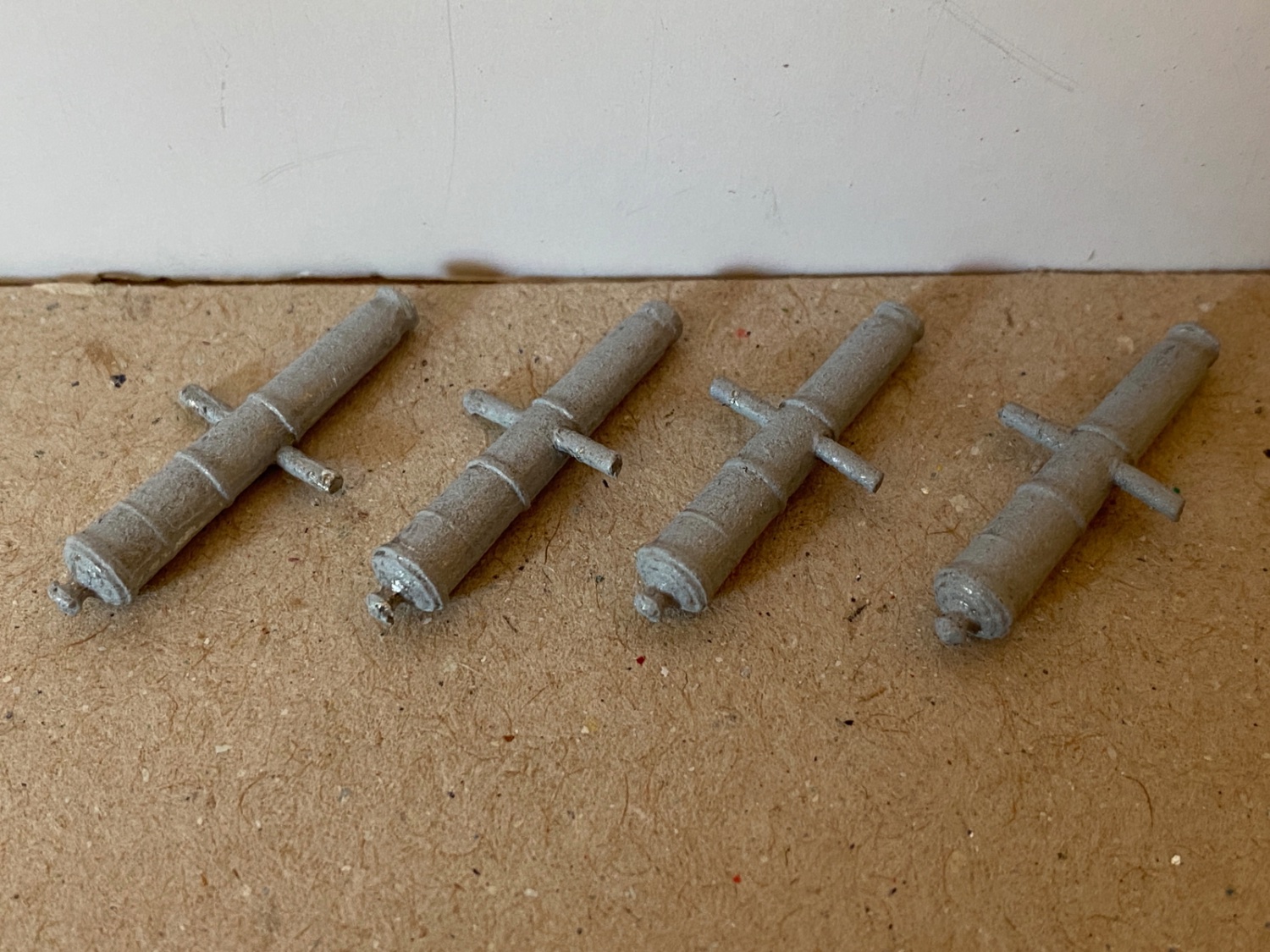
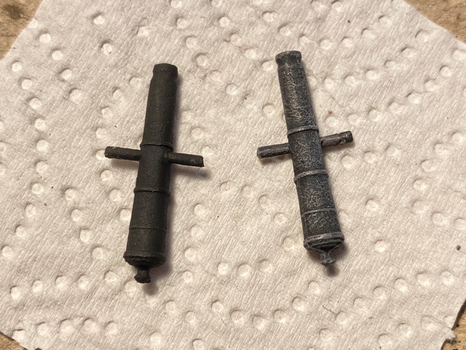
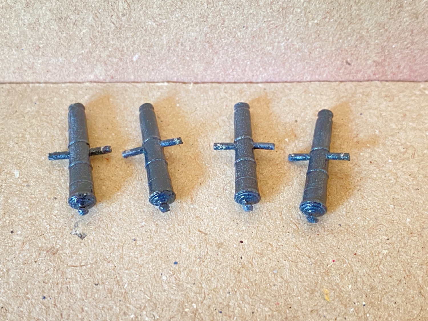
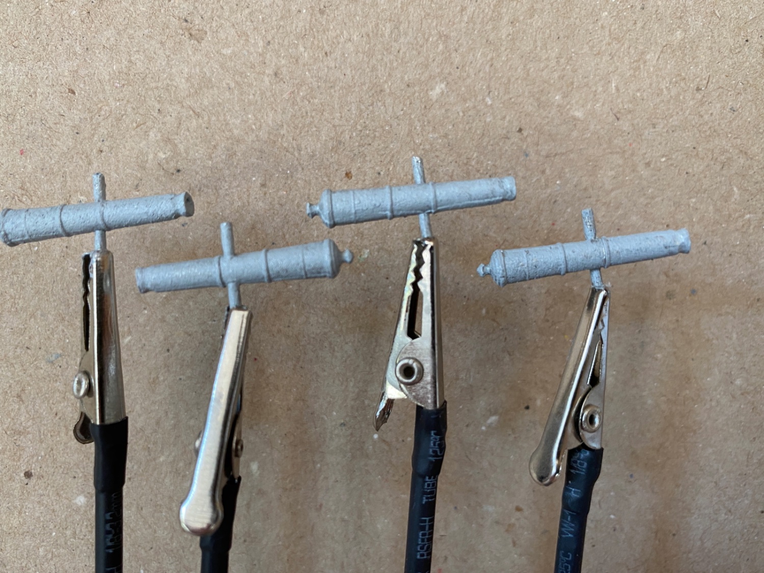
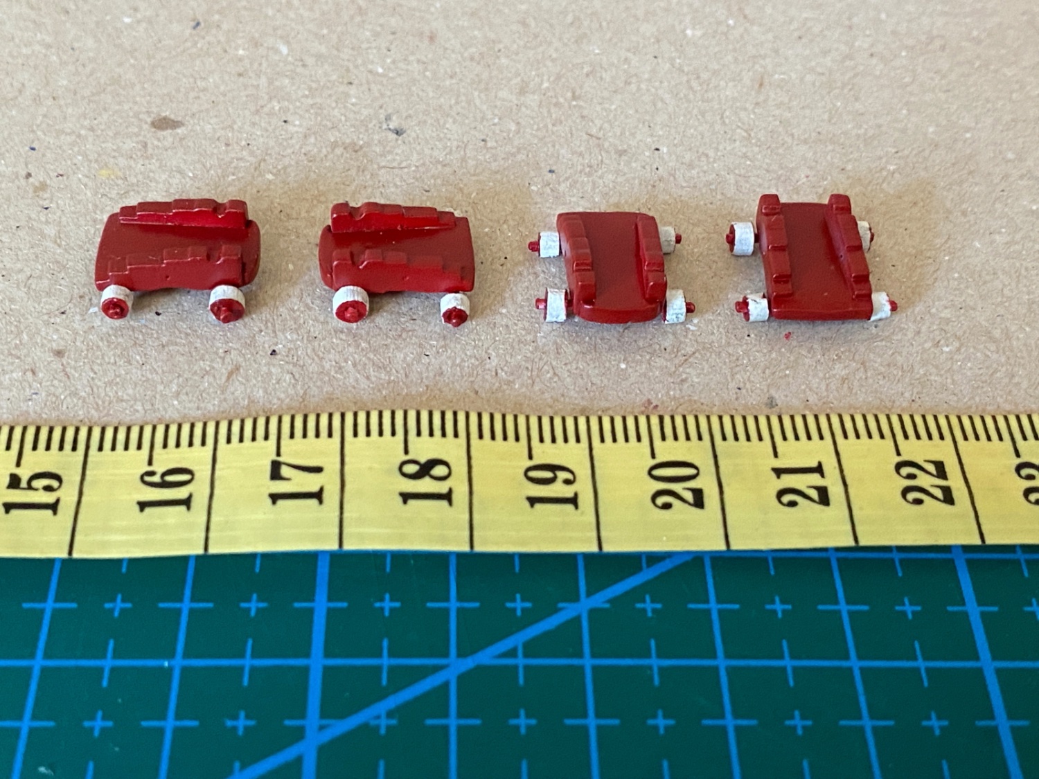
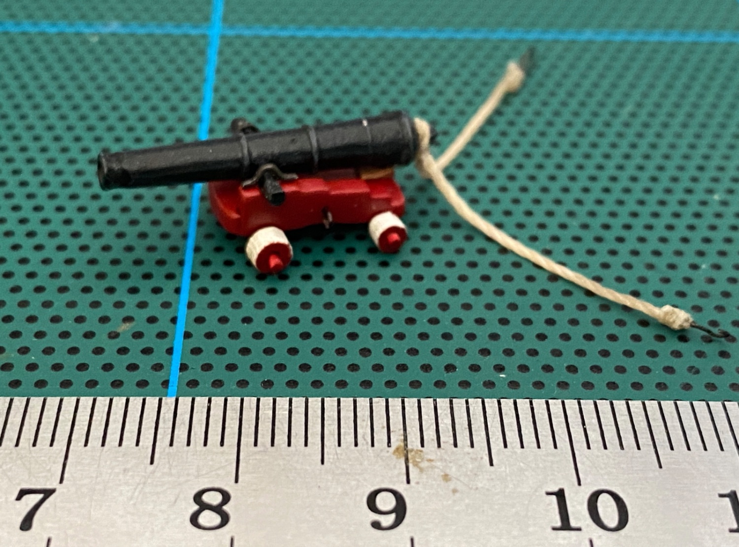
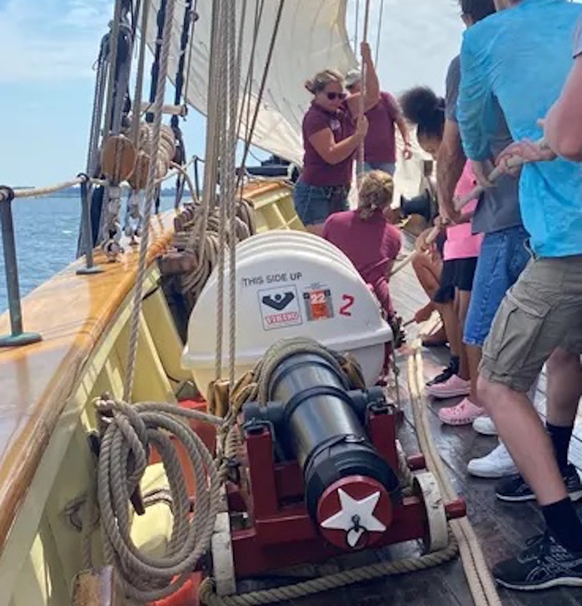
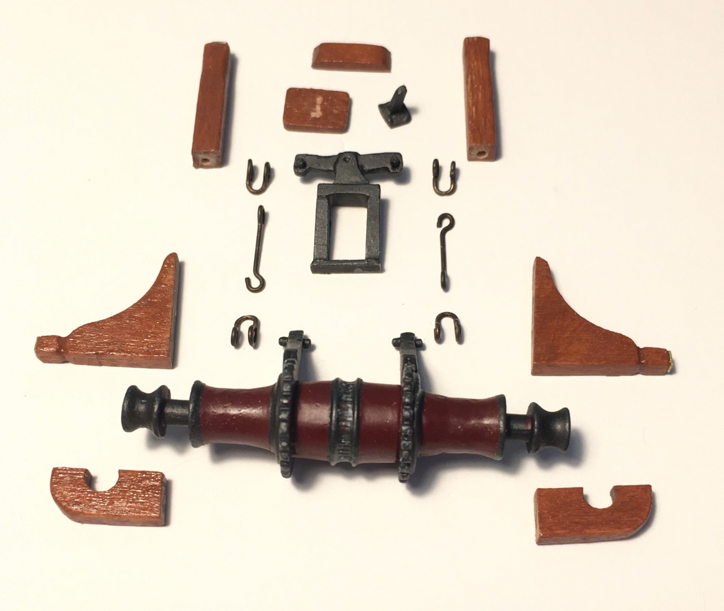
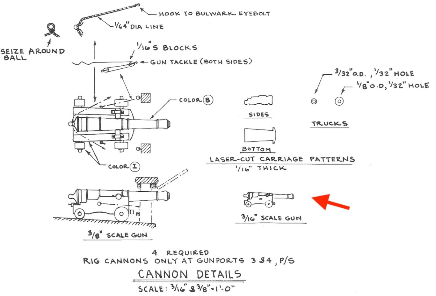
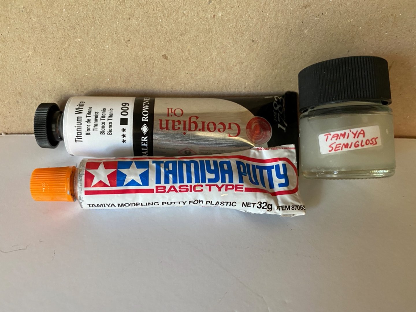
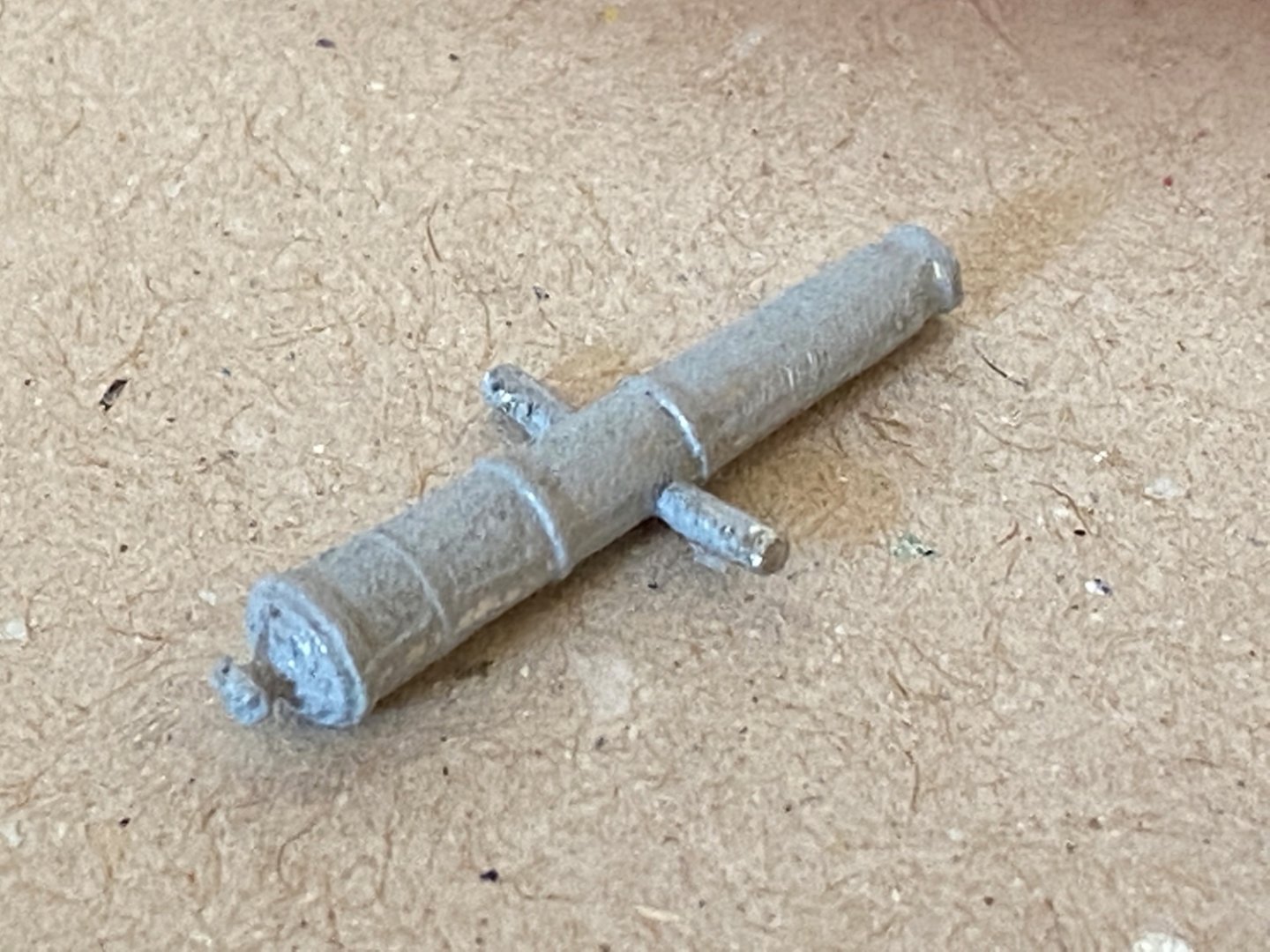
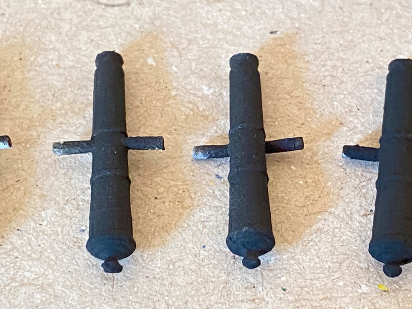
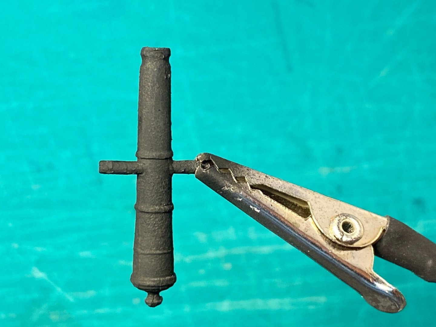
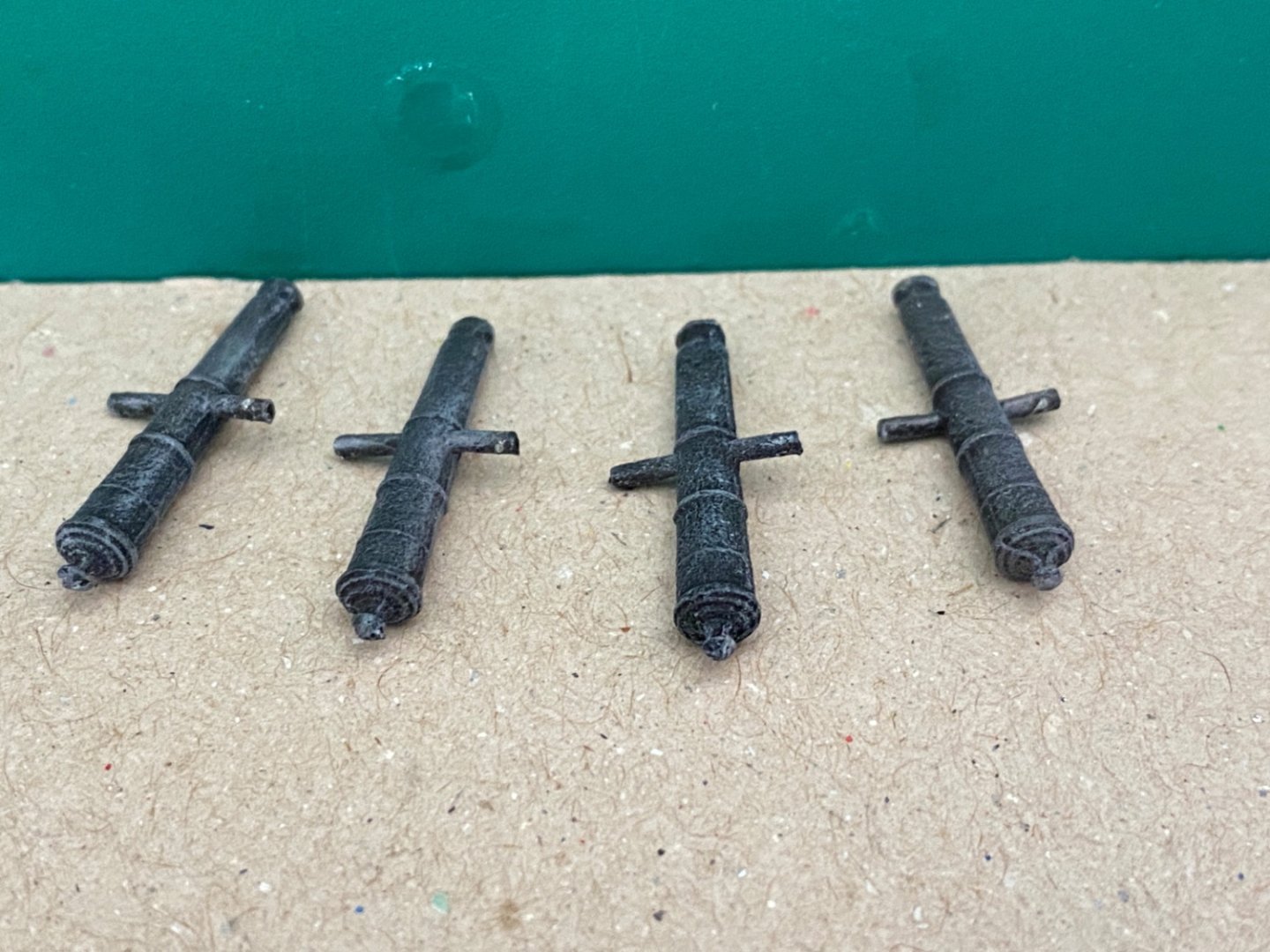
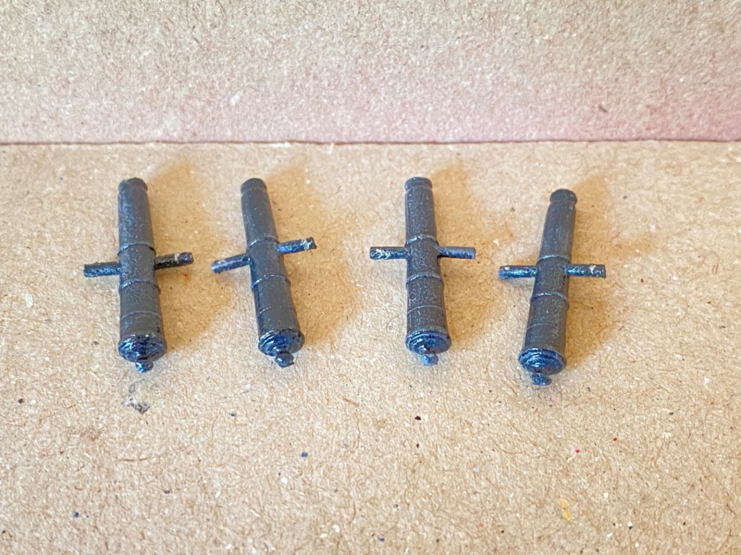
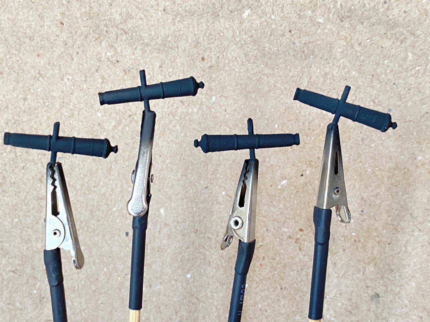
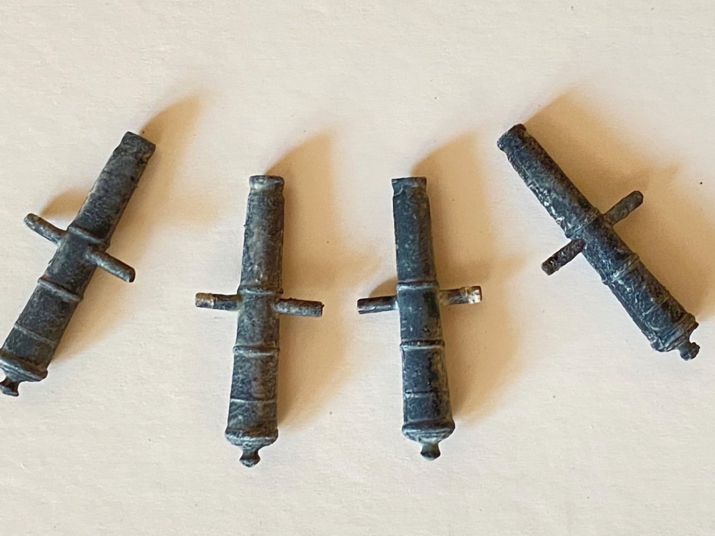
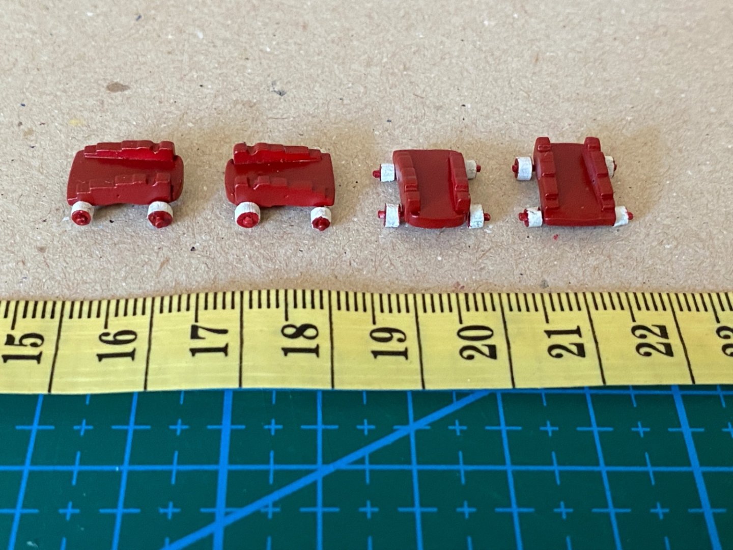
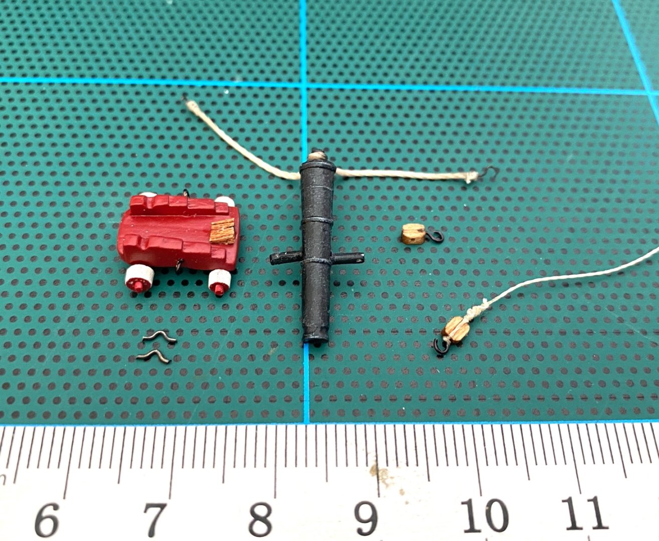
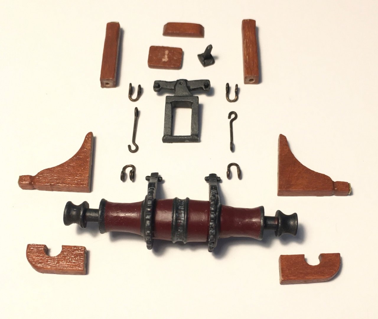
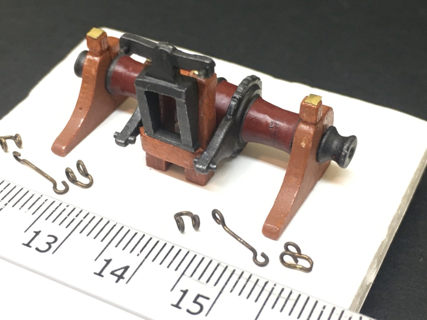
Cannons of the kit were also out of scale. The length of the cannons must be 22 mm (7/8 inch) when you measure it on the plan. However kit's cannon's length was 27 mm ( roughly 1 7/8 inch). I looked for third party items without any success. So I decided to cut the cannons at their front tip and tried to shape the cut tip. I painted the cannons with a method described by our local forum's moderator, Kazim Gurhan. For this method Tamiya basic putty, matt black paint, titanium white oil paint, satin clear coat and a dry cut brush were used. Tamiya basic putty, diluted with lacquer thinner with a ratio of 1 part putty to 1/2 part thinner, was applied with a dry brush with quick strokes on the cannons and left to dry. The result must be a slightly particuled surface. The next step is black matt paint. I used Tamiya XF-2 with airbrush. After the black paint was cured, titanium white oil paint was dry brushed on the surface. The amount of the paint on the brush must be the minimal amount. The goal here was to highlight the particules of putty on the surface. The last step was satin coat application. I used Tamiya semi gloss but the result was far from satisfactory as the surface was too shiny. So I started from step one again, after removing the paint and putty.This time I used clear matt coat in the last step. This time the result seemed OK. The cannon carriages were assembled and painted. Together with their rigging and details cannons and carriages were ready to be installed. The cannons were to be placed in gunport 3 and 4 on starboard and port side with the gun port lids open and the tips of the cannons exceed the gunport. However there are many photos of the real ship where the gunport lids were closed and the cannons were stowed paralel to the bulwarks, even when sailing. So I decided to install the cannons just like you see at the photo above, stowed parallel to the bulwarks.


- 114 replies
-
- 4
-
-
- Pride of Baltimore II
- Model Shipways
- (and 1 more)
-
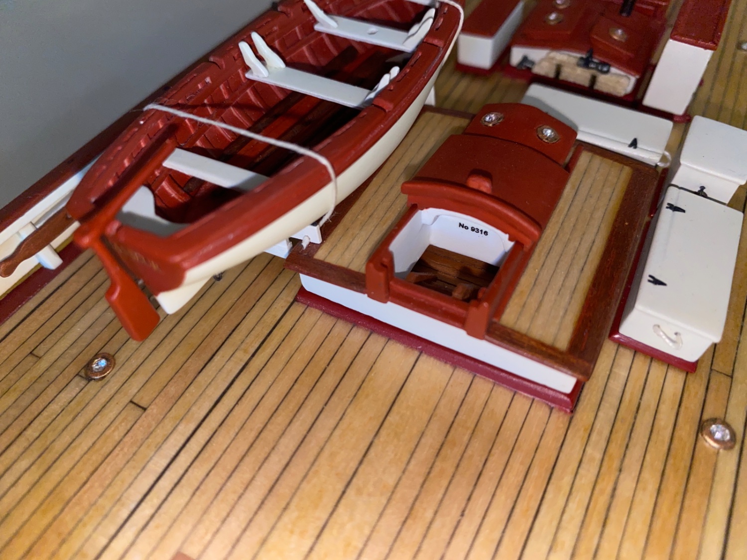
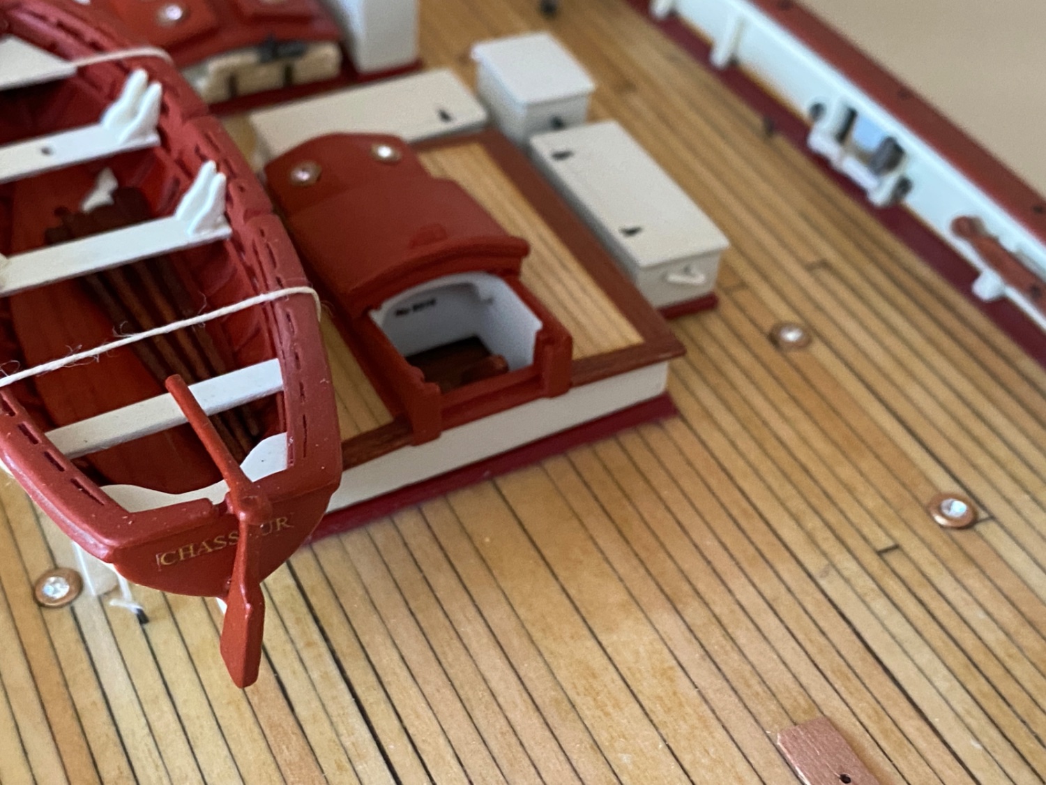
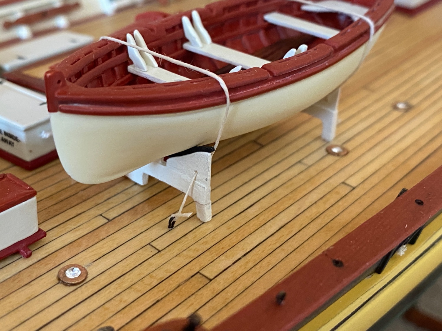
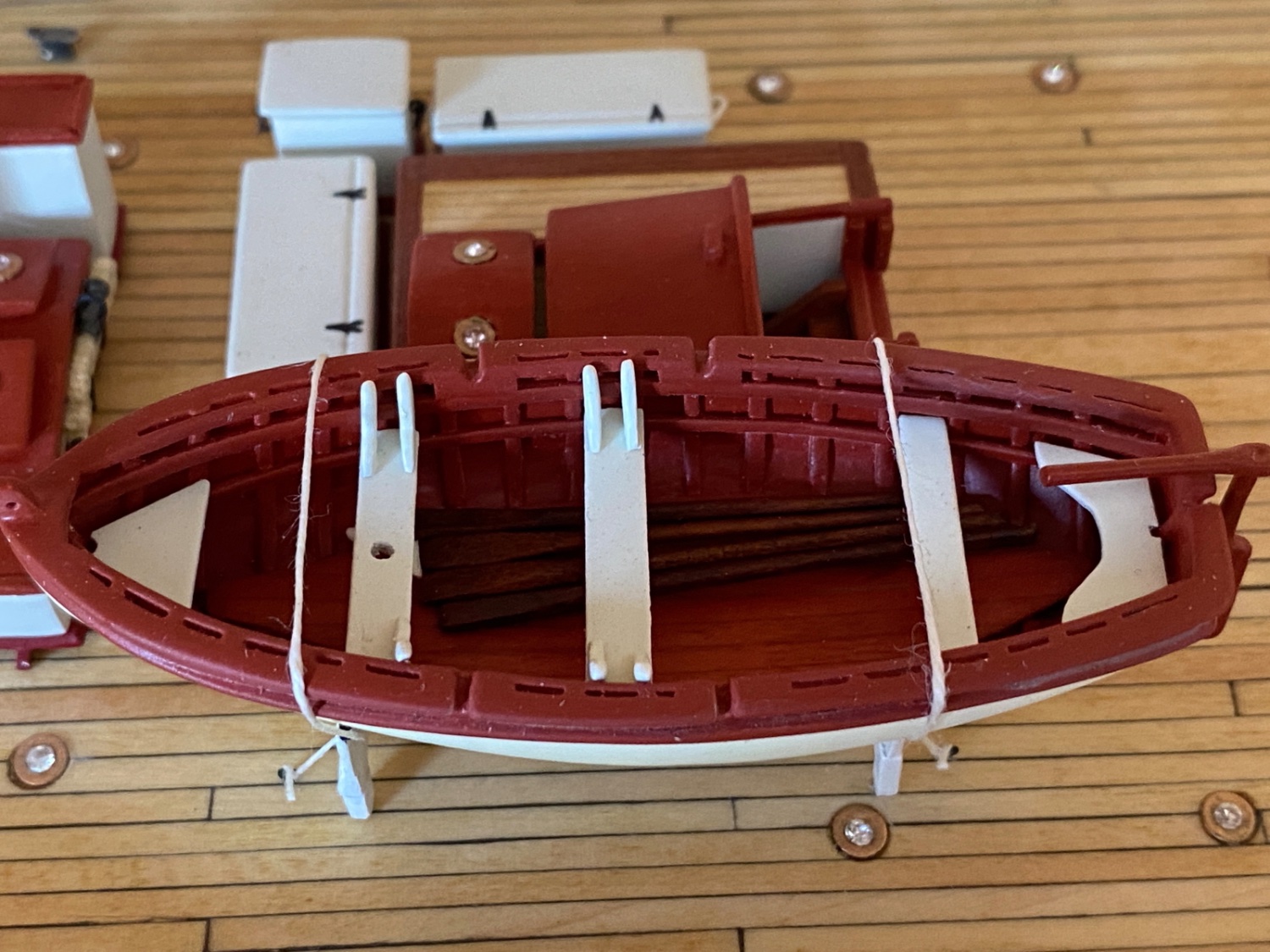
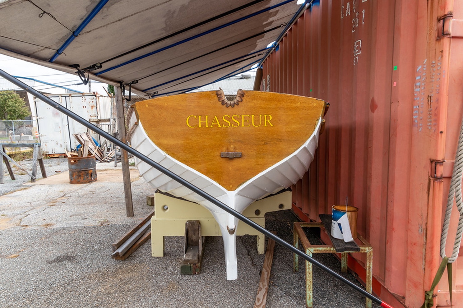
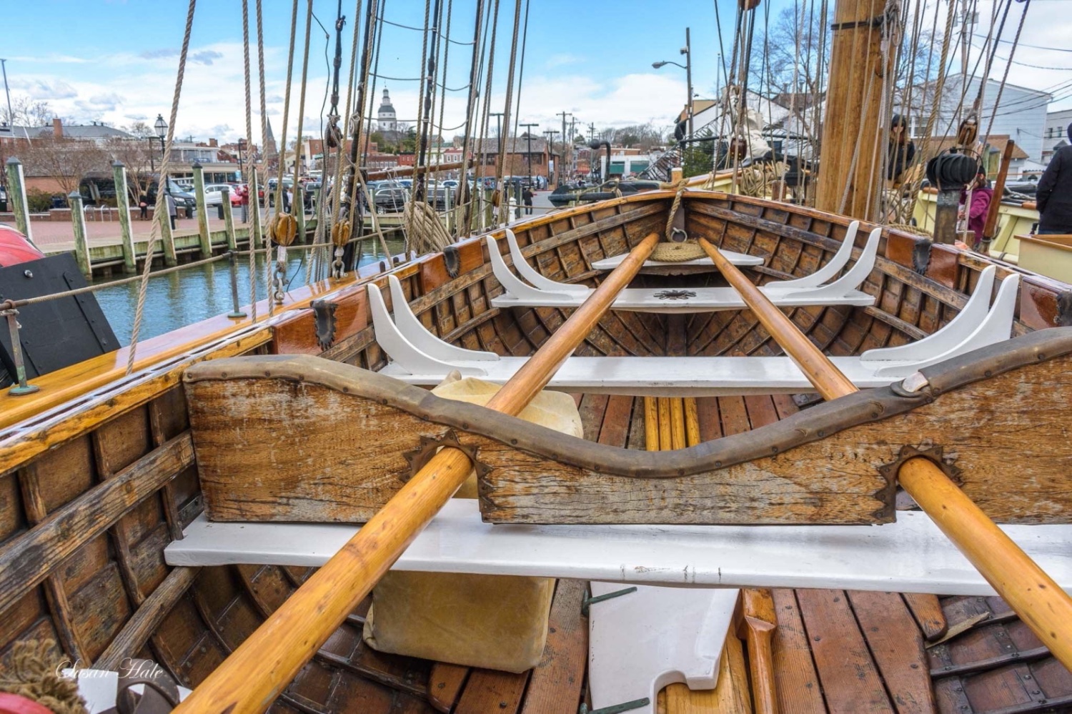
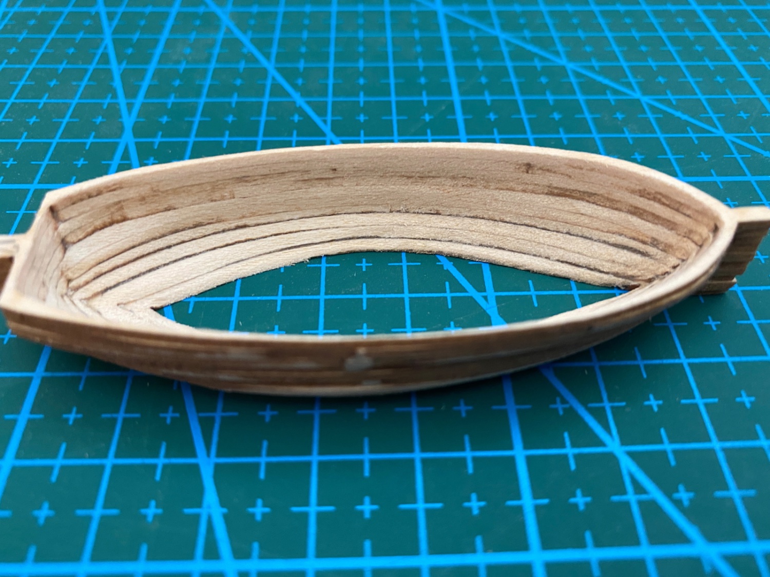
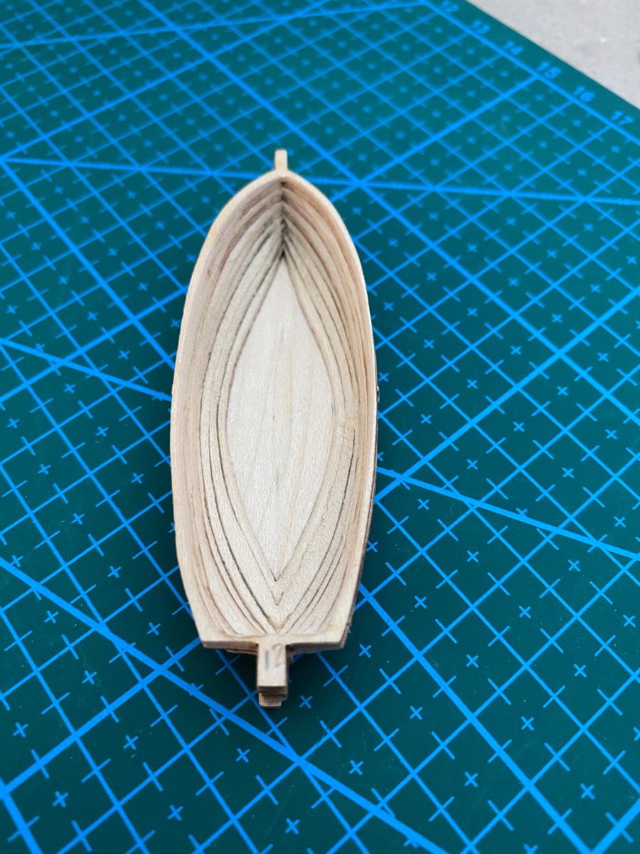
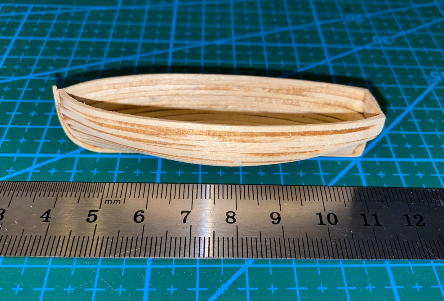
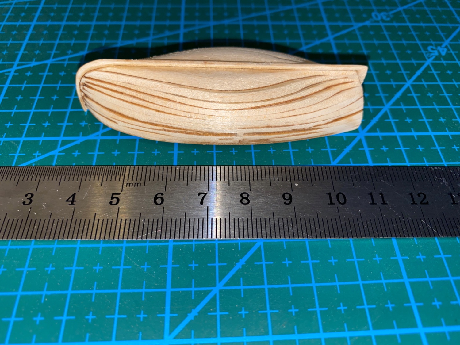
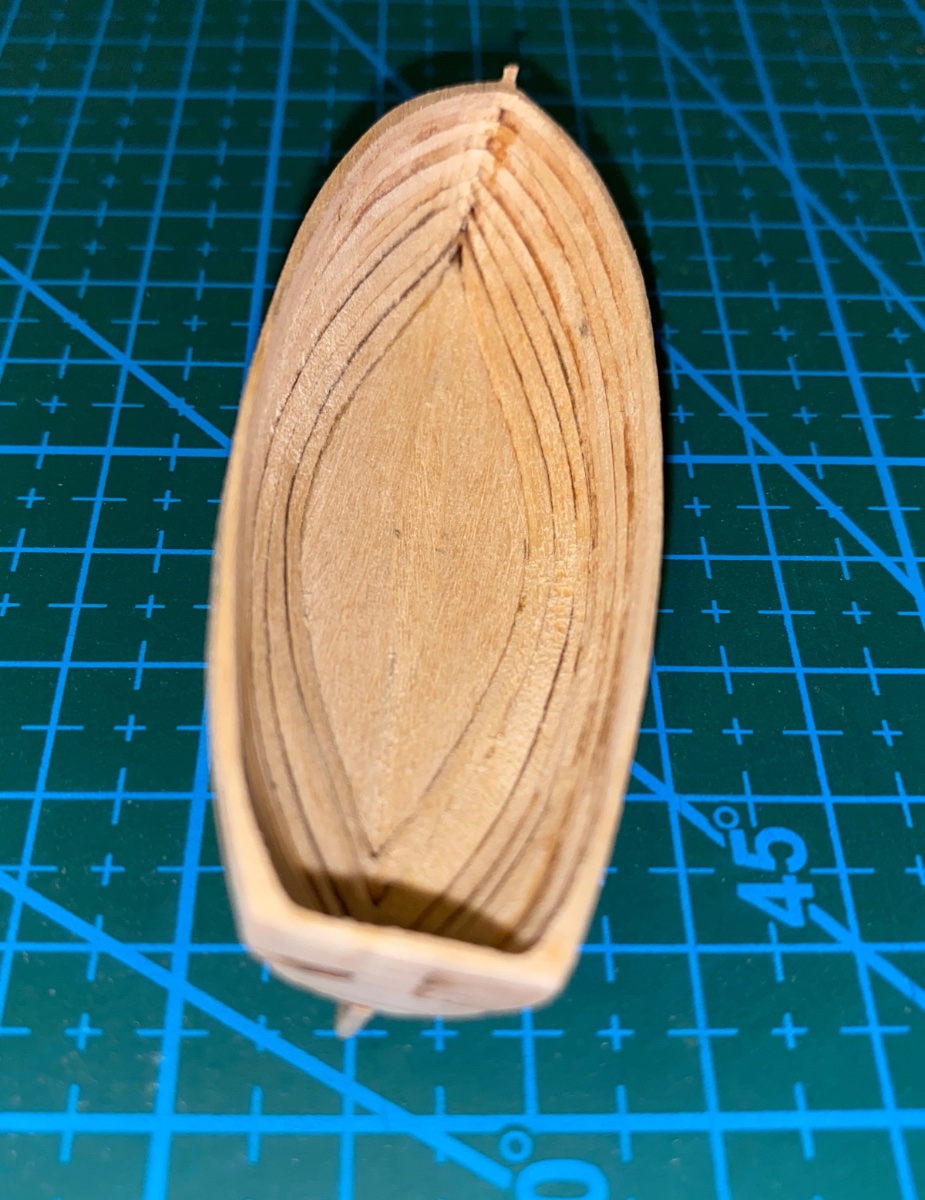
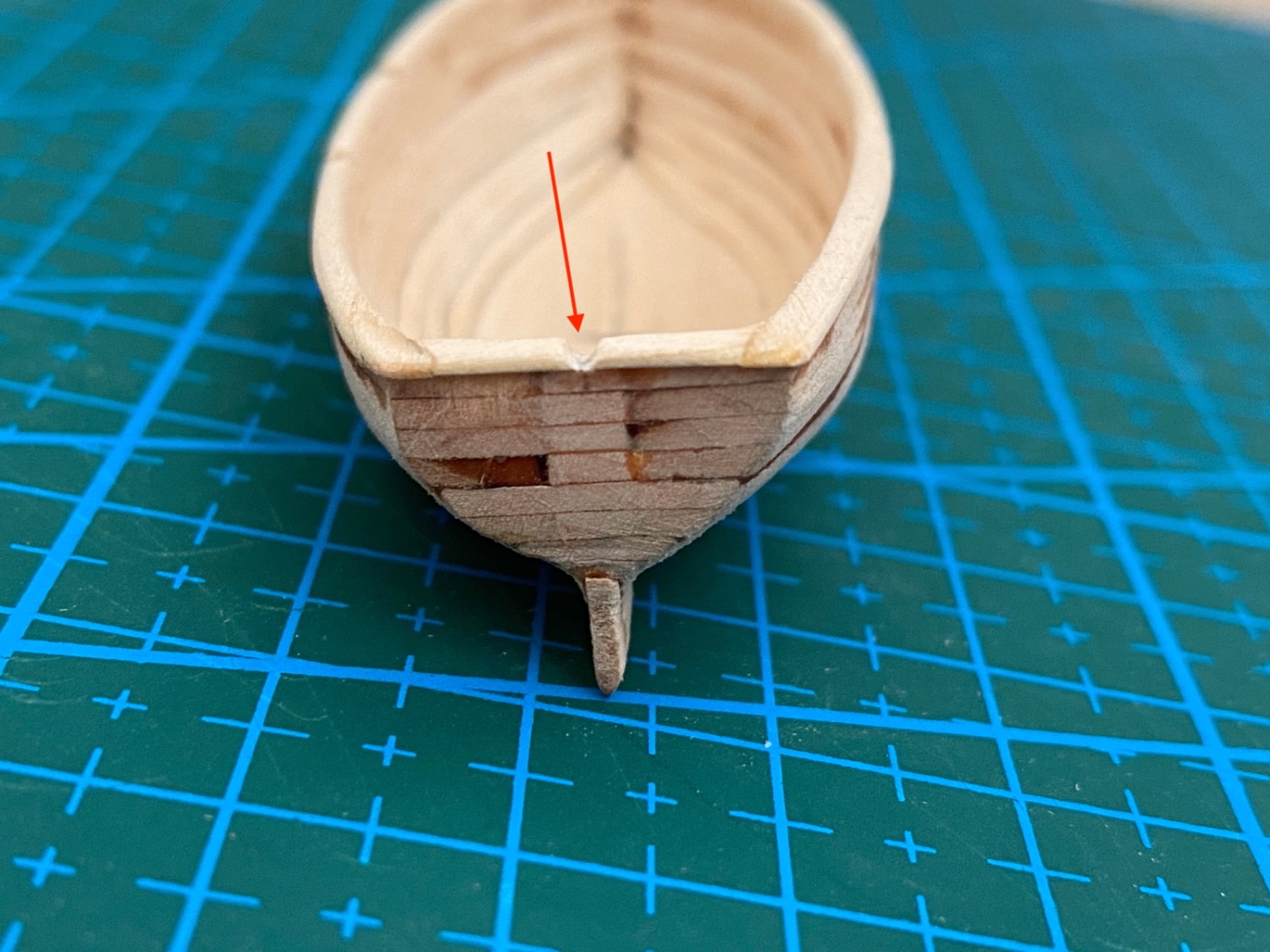
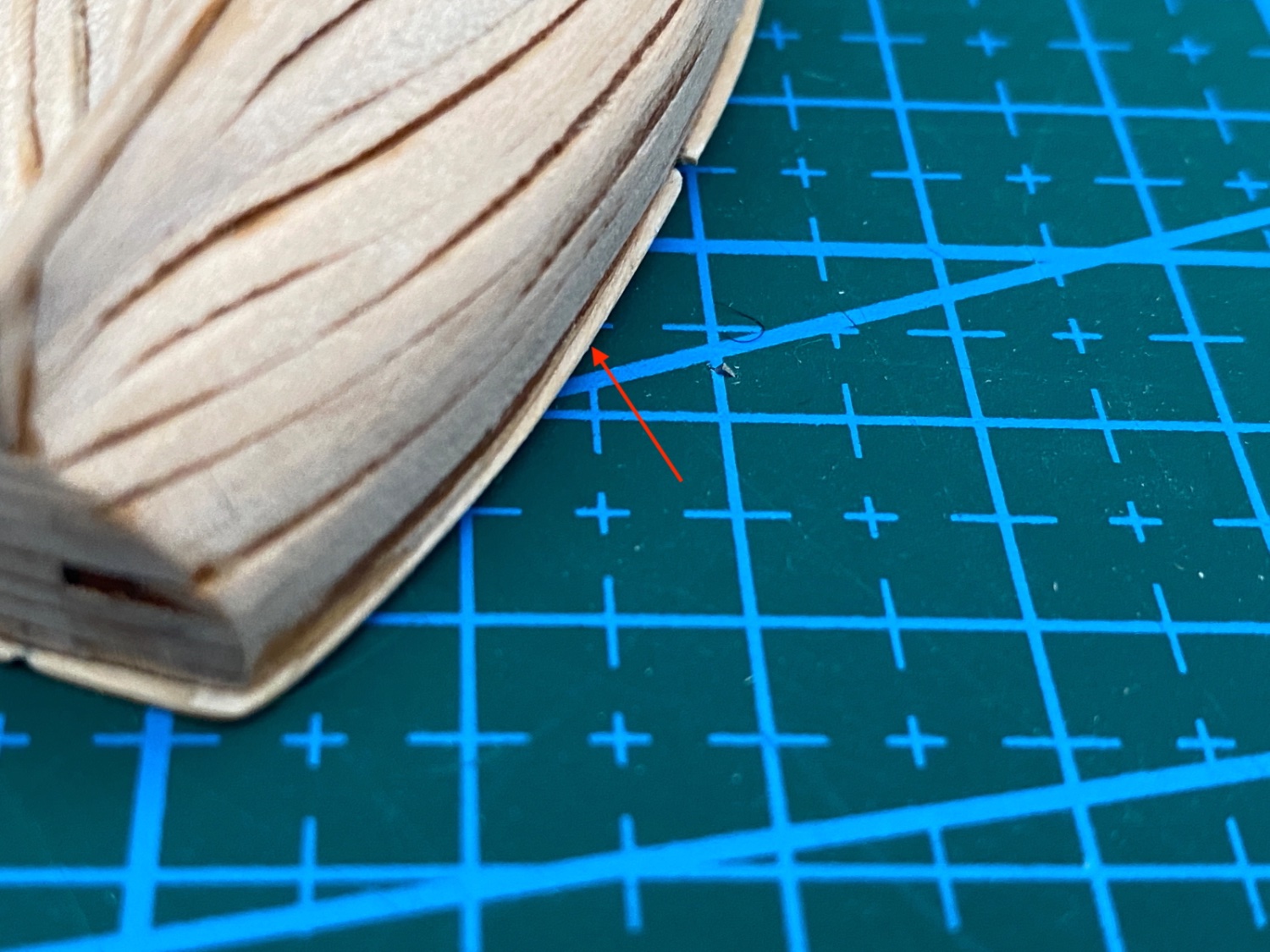
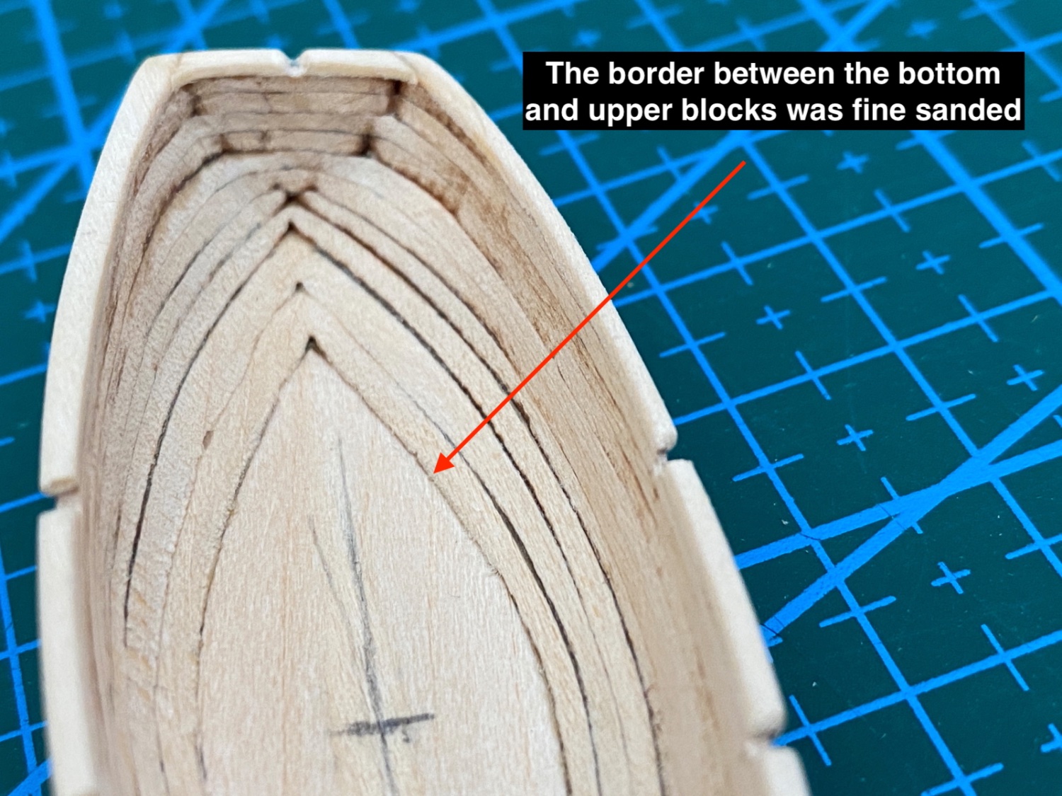
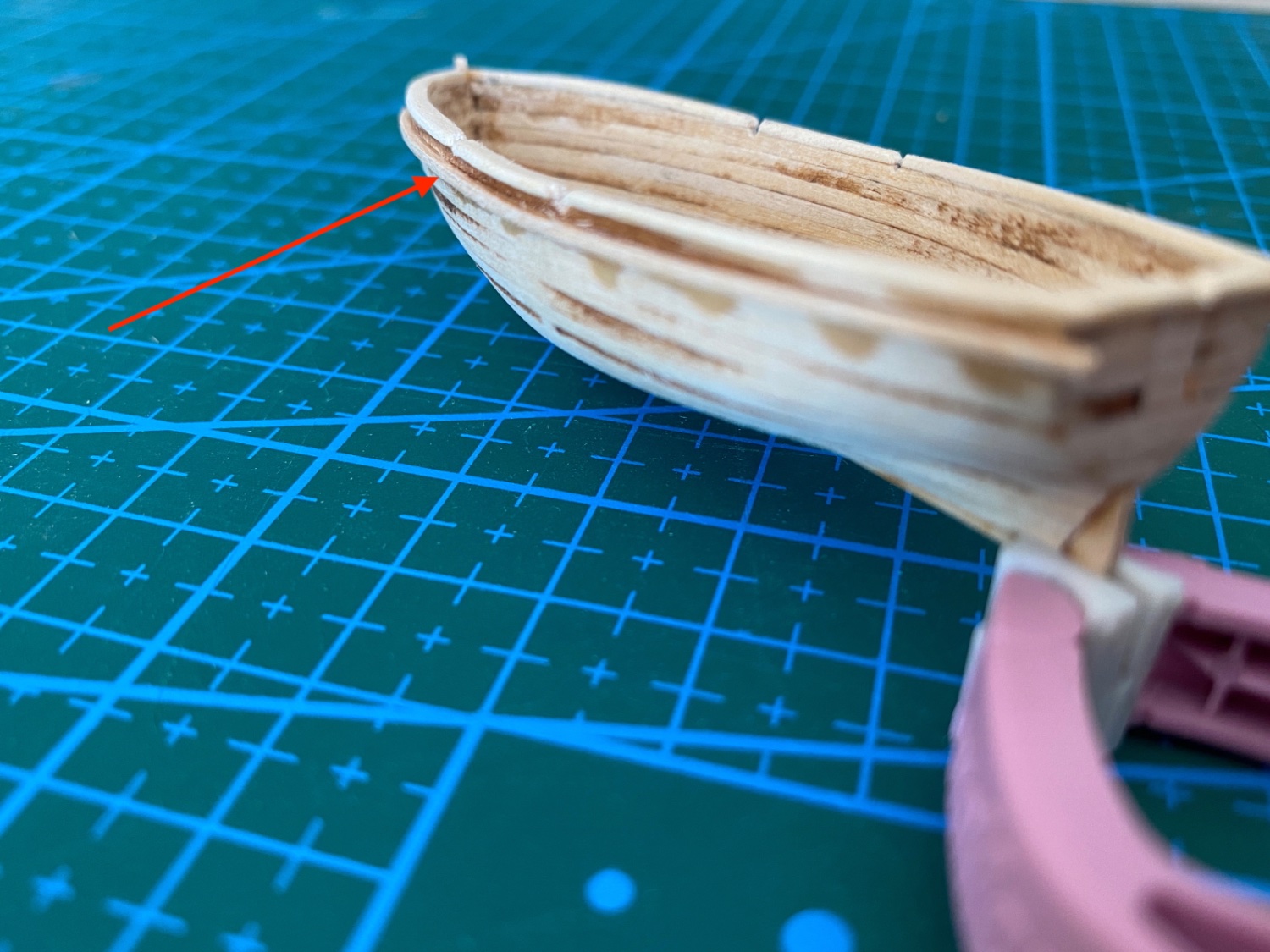
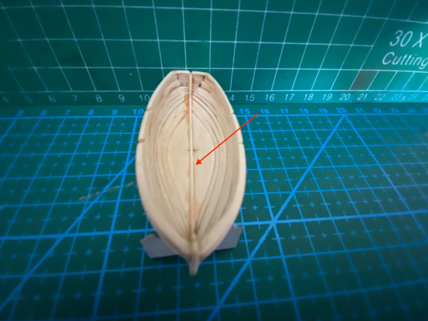
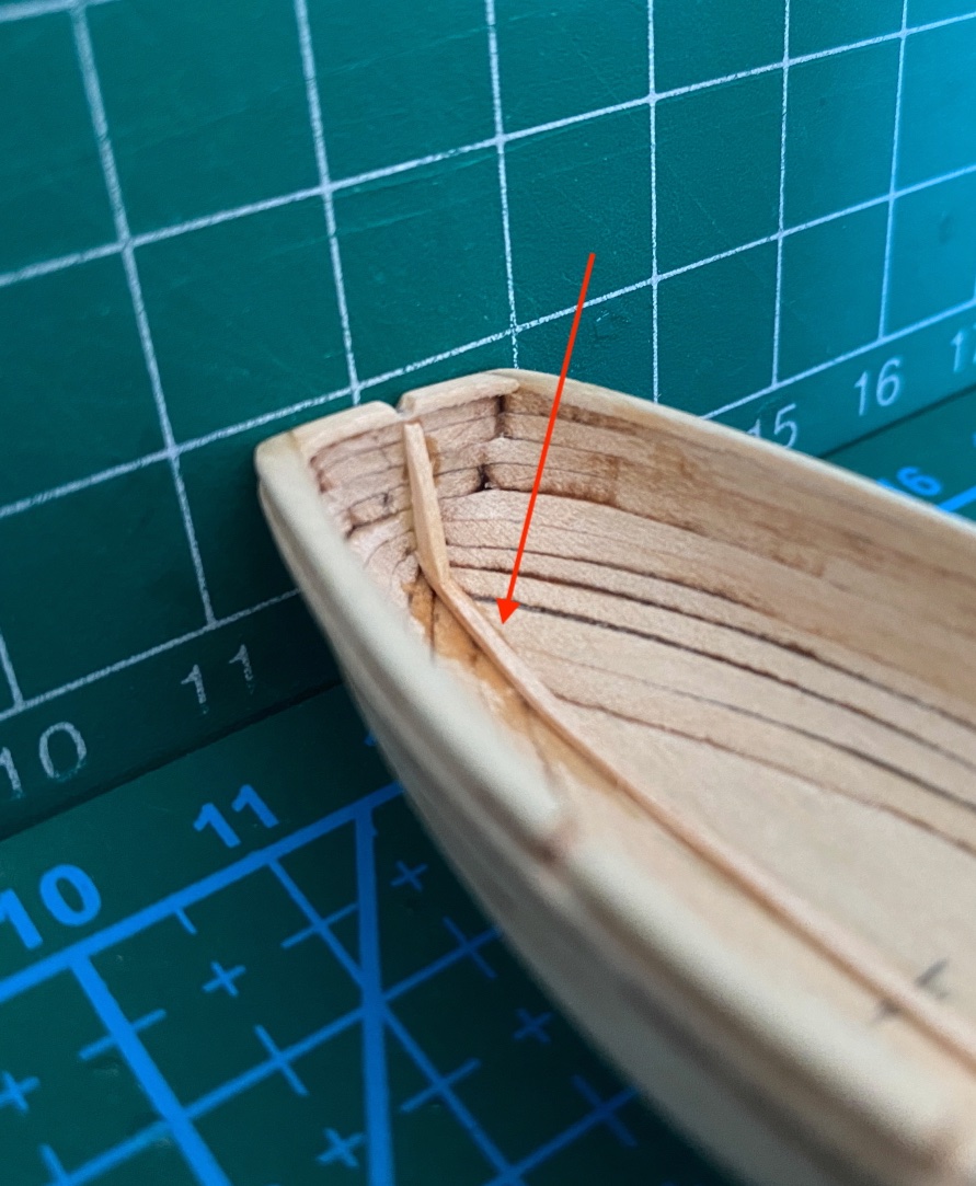
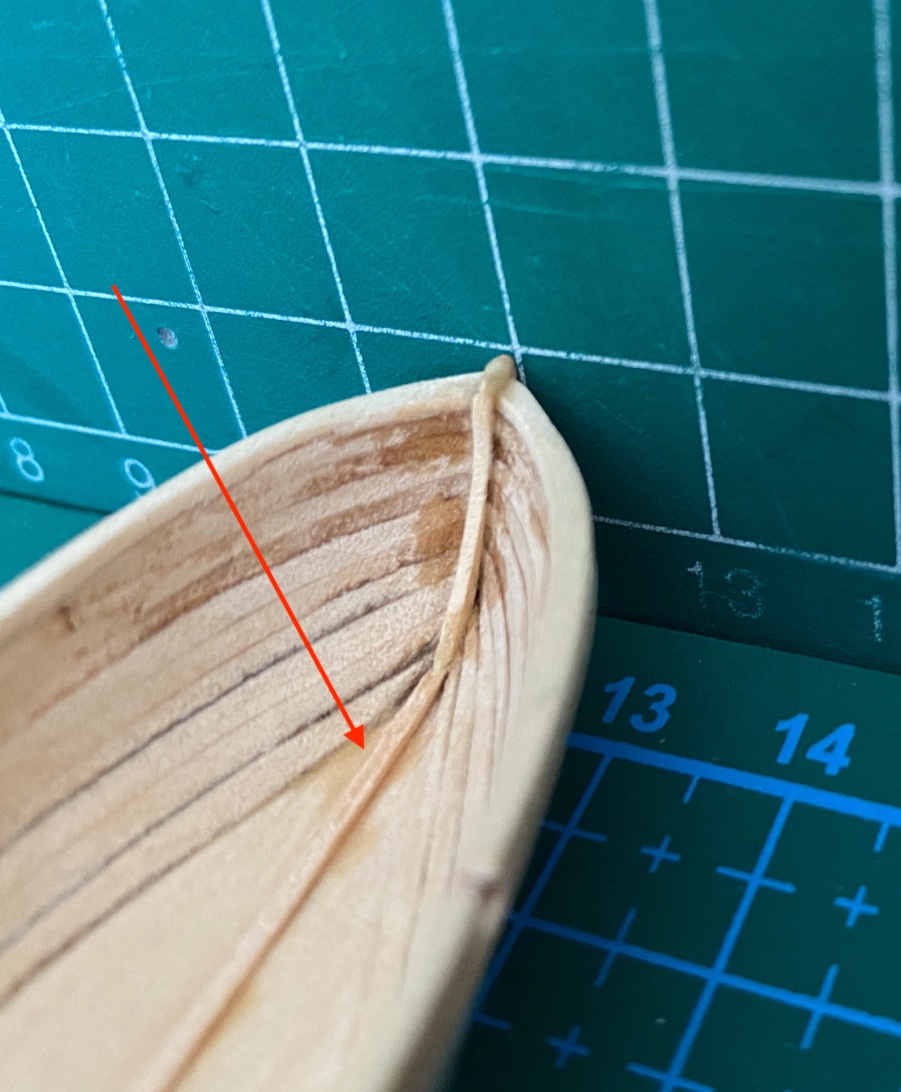
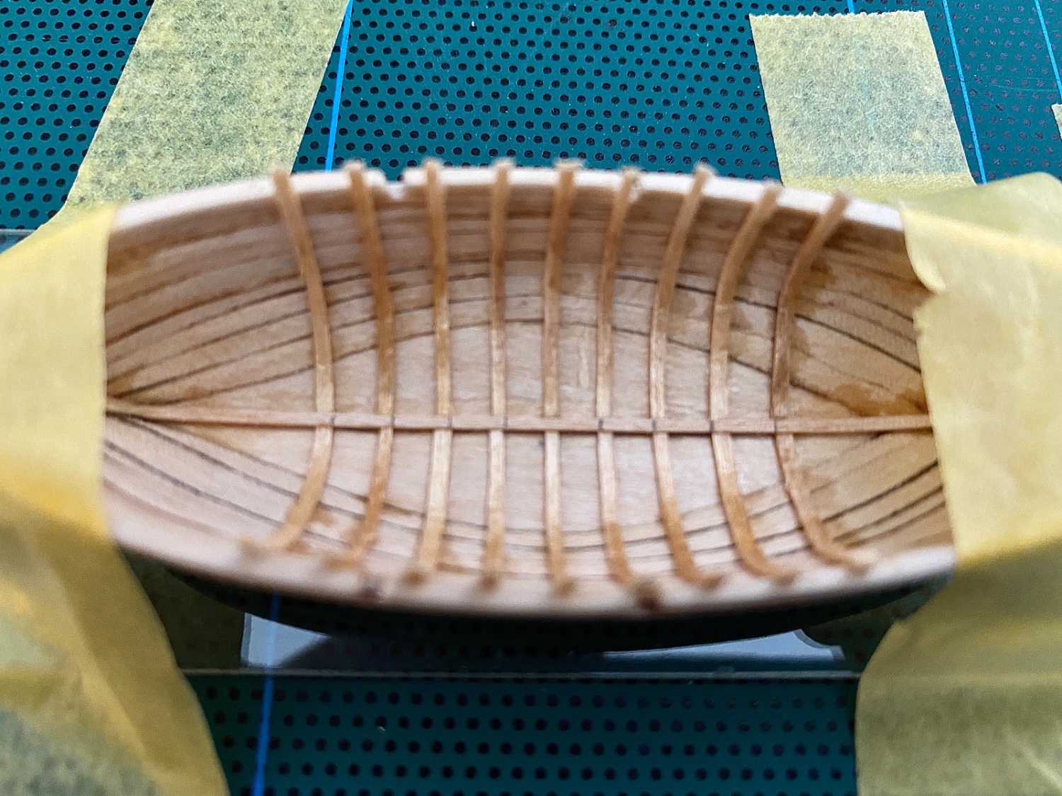
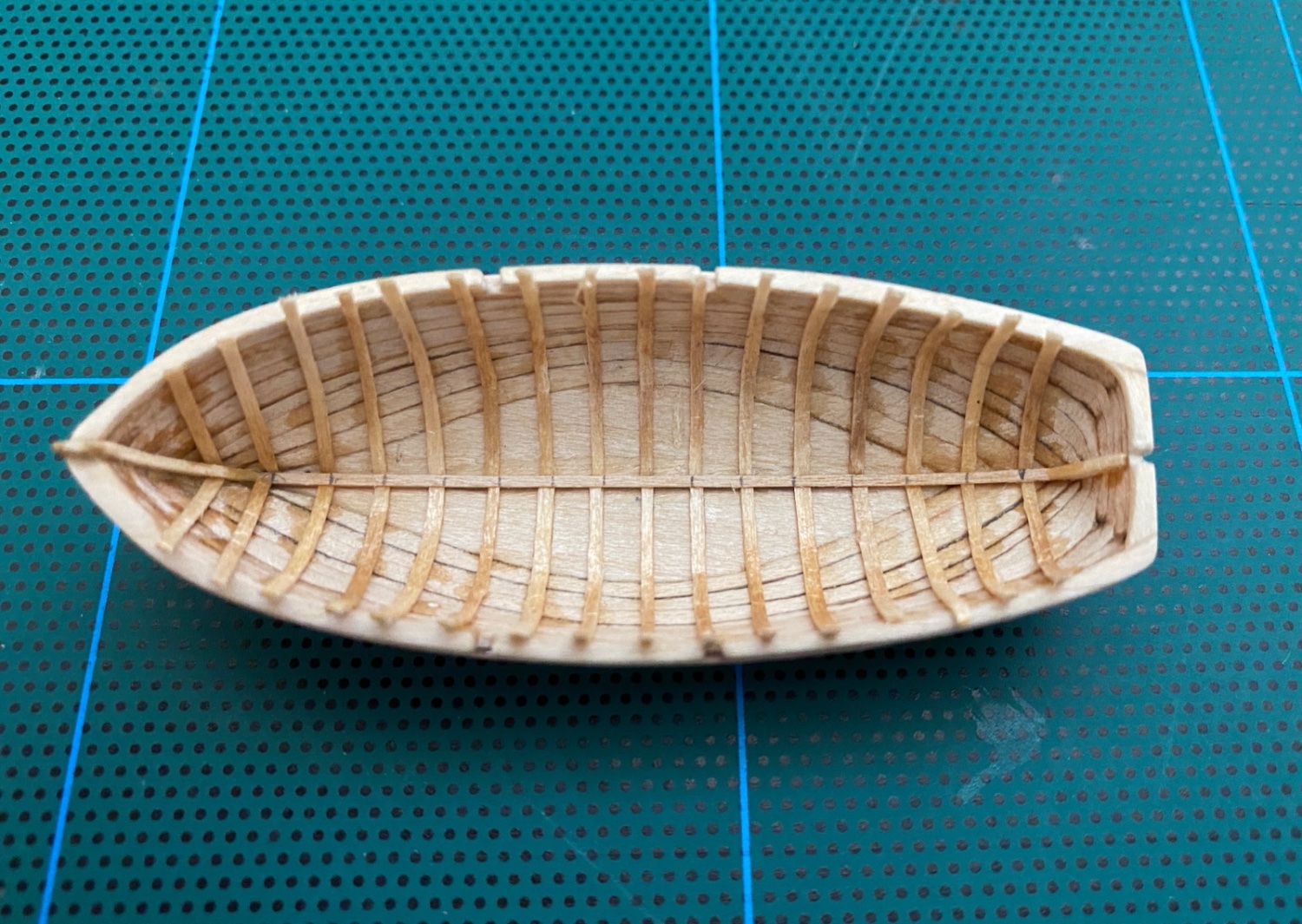
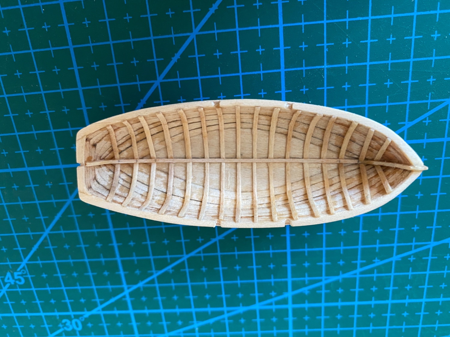
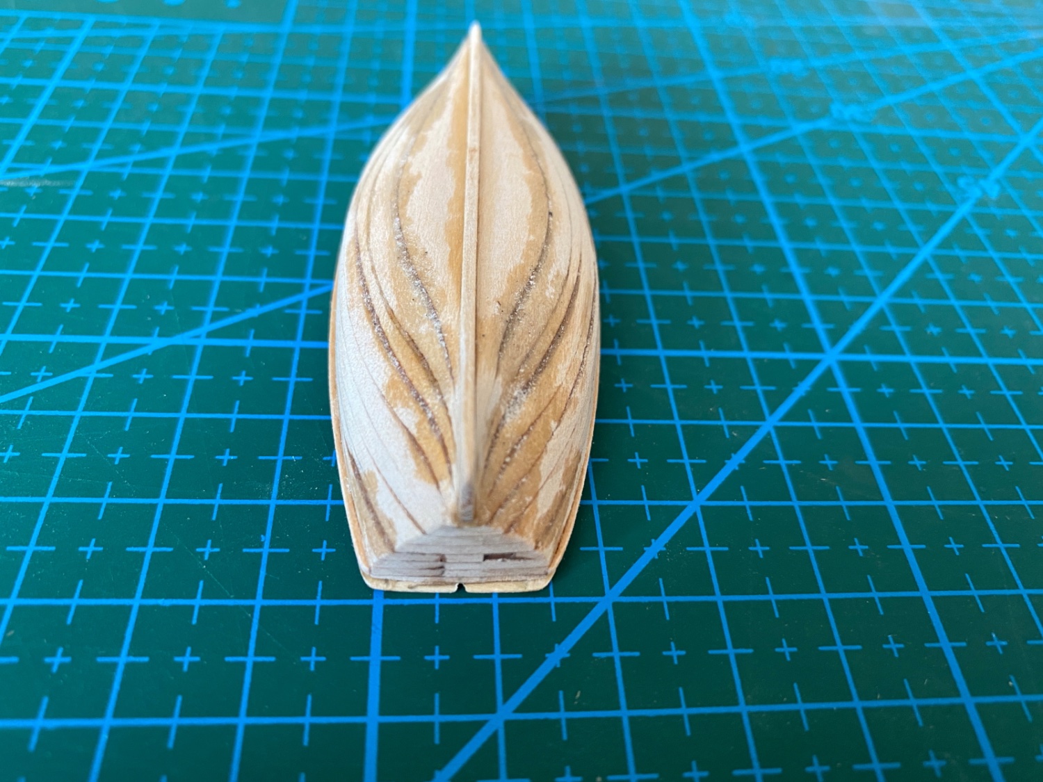
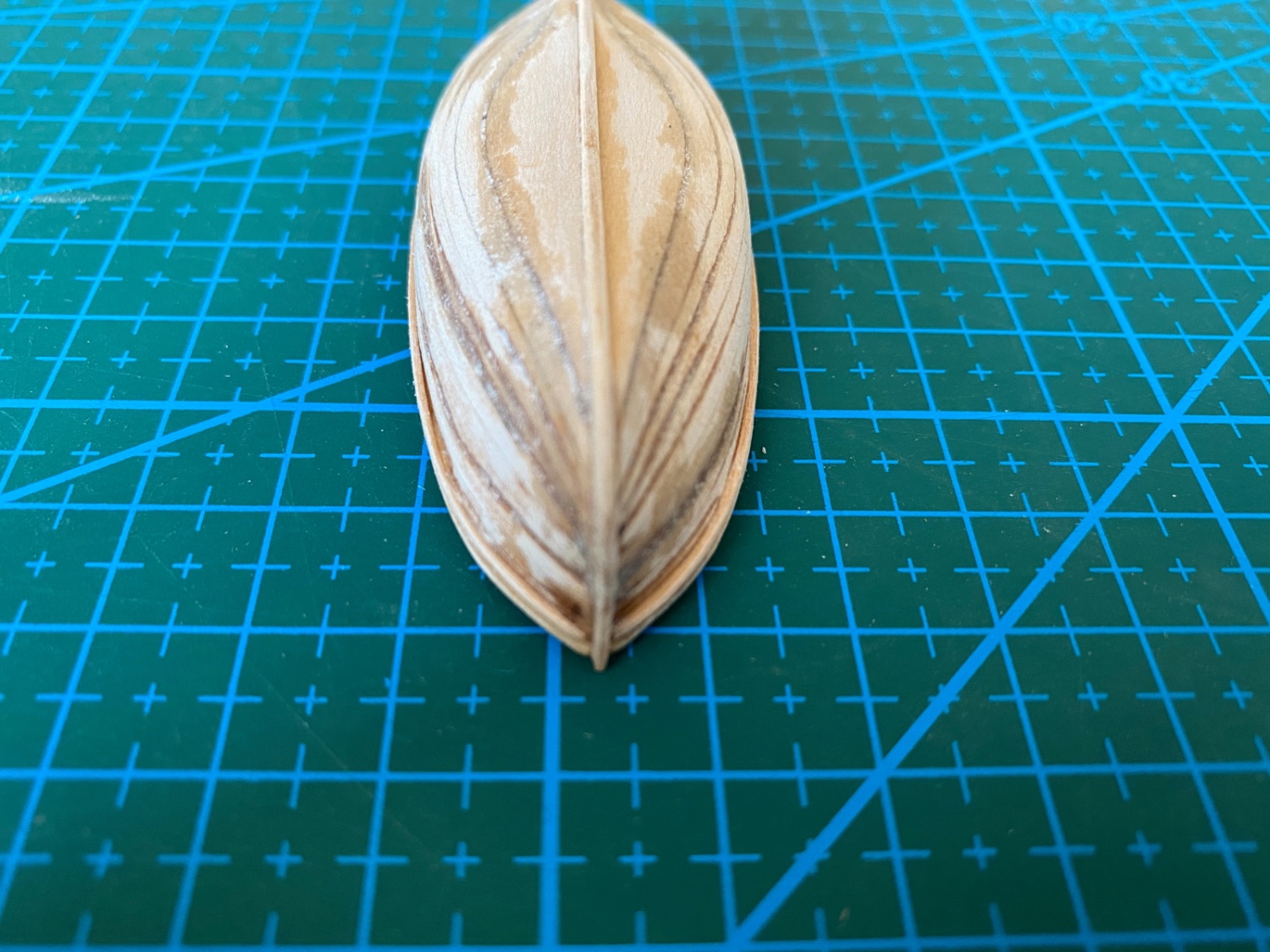
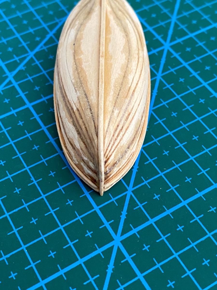
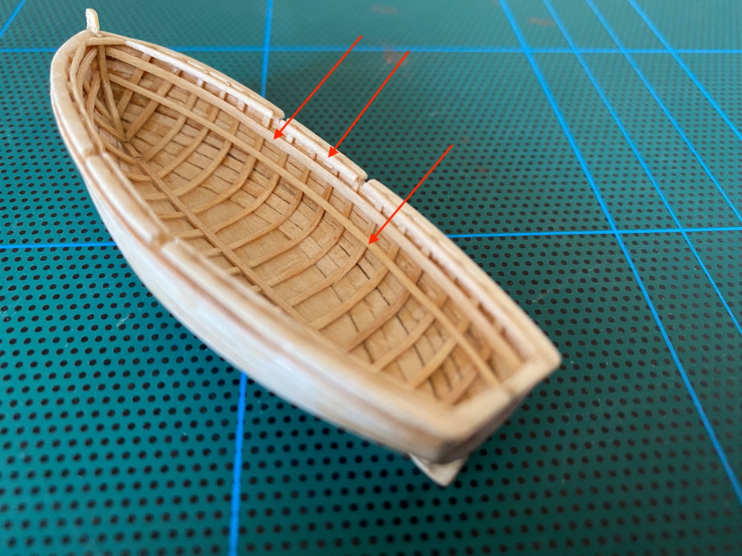
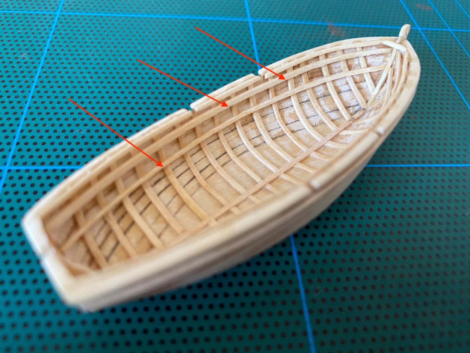
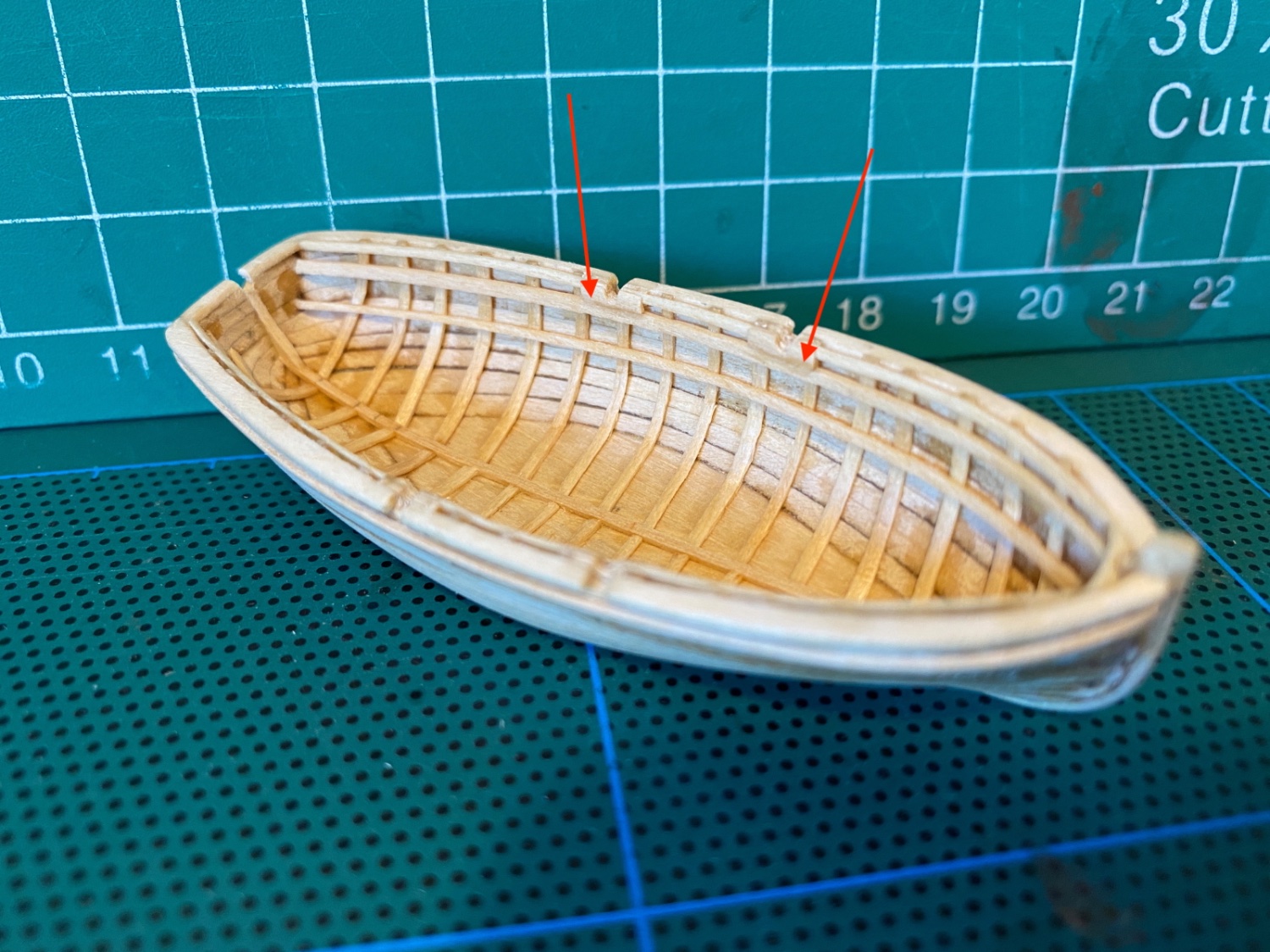
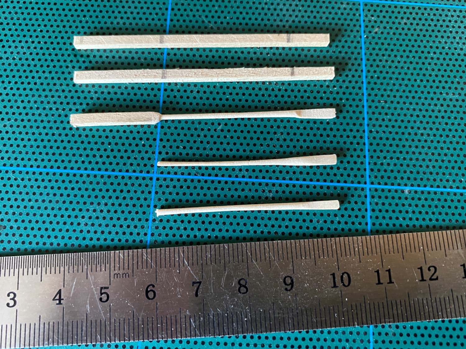
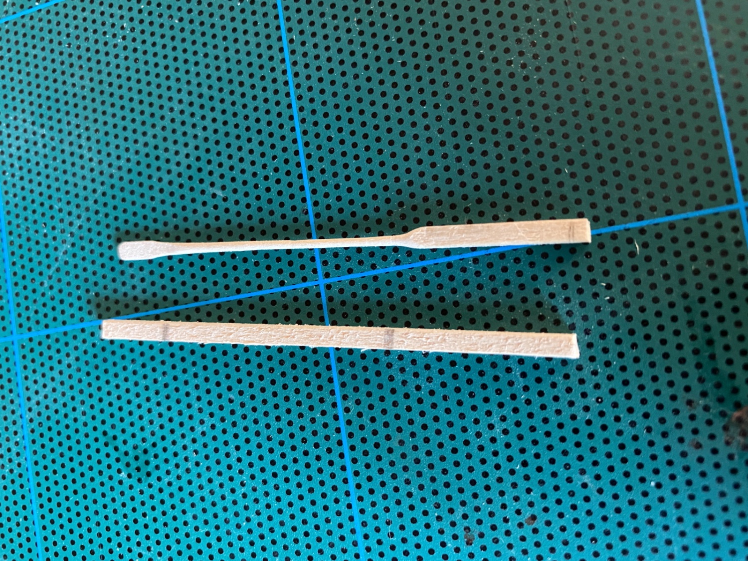
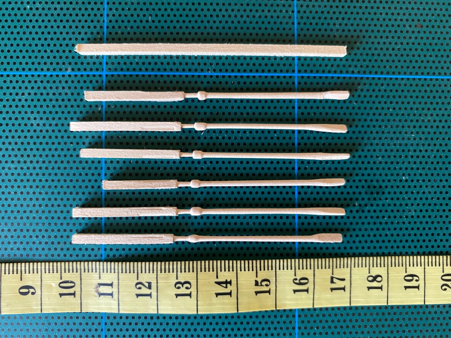
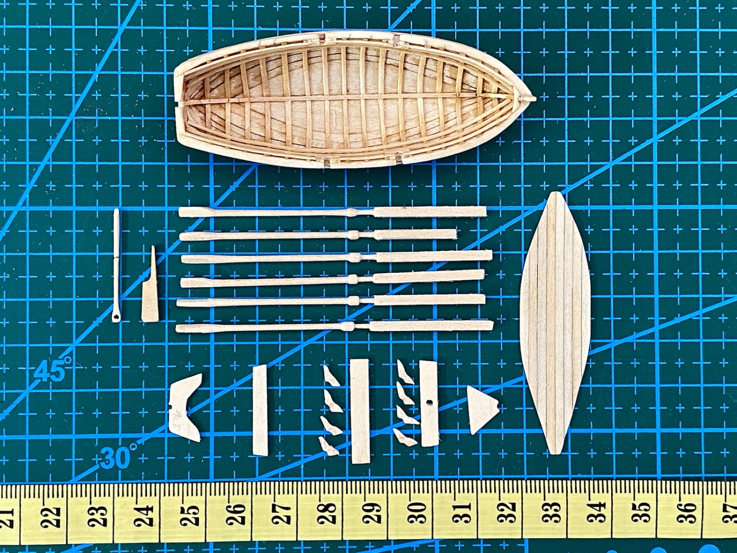
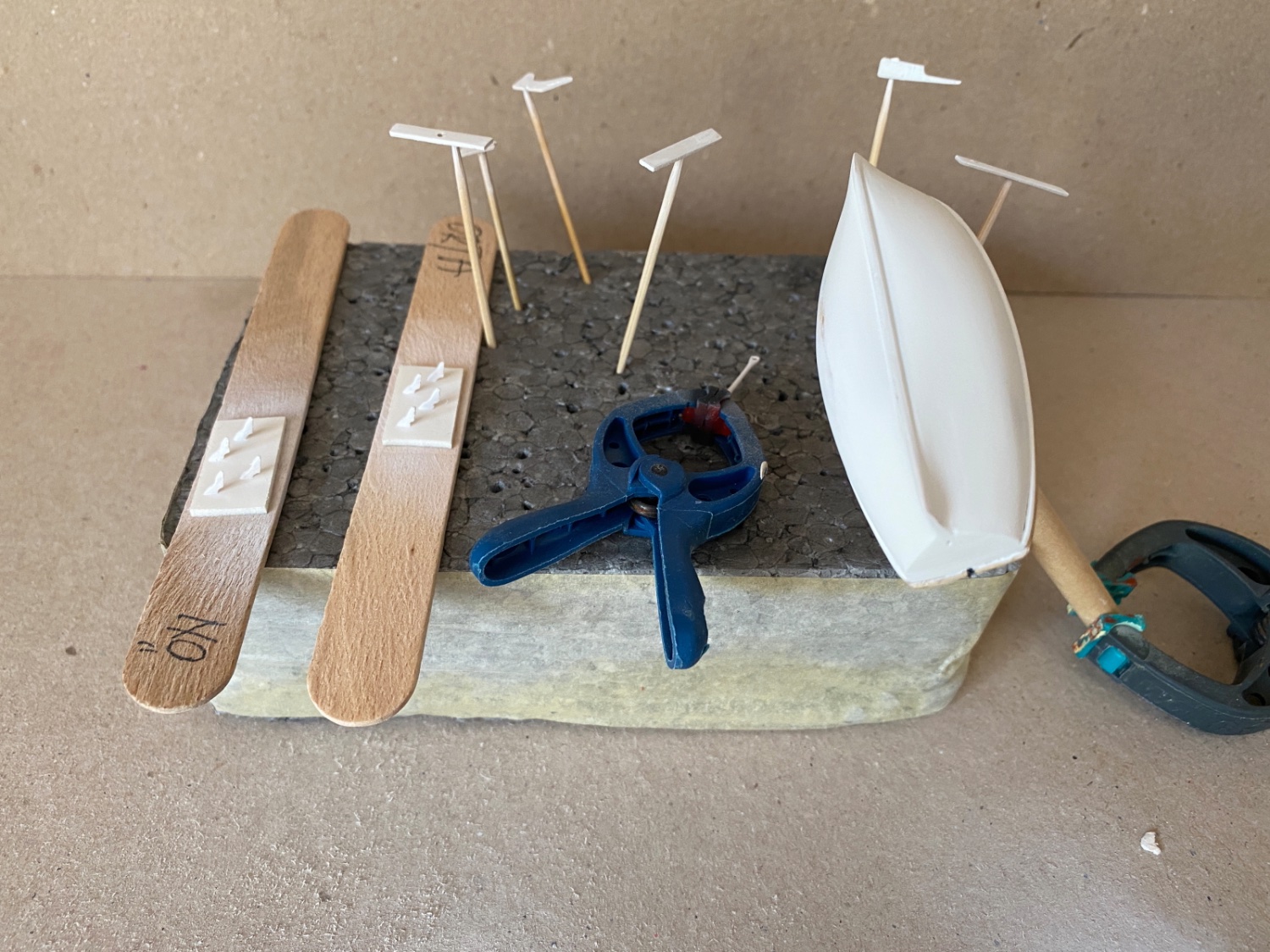
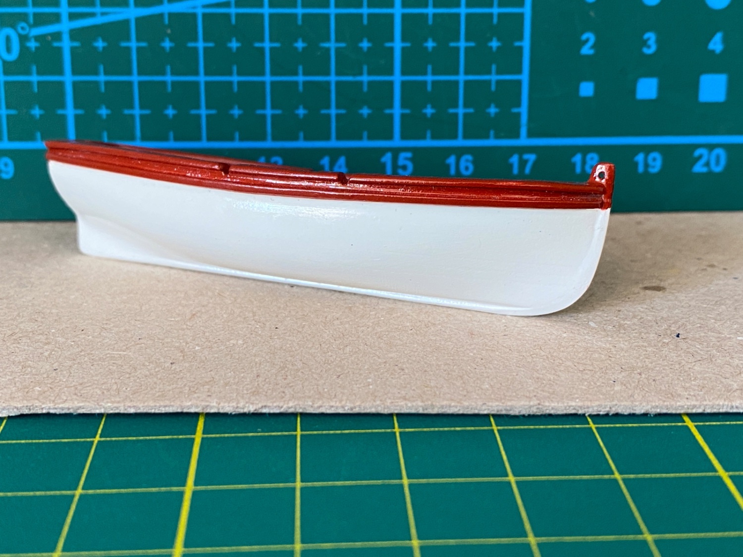
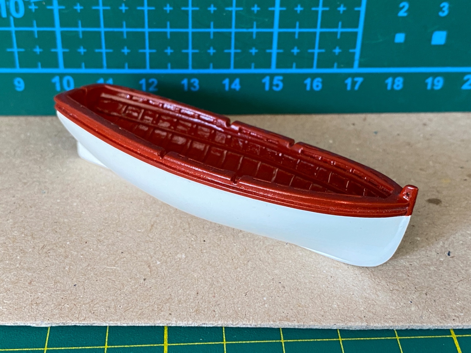
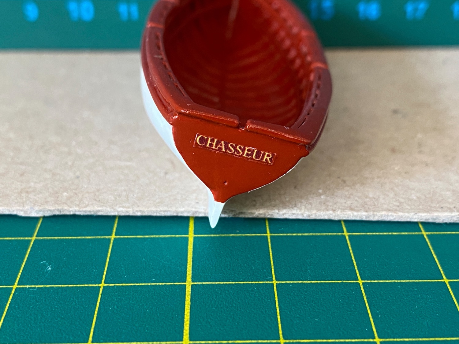
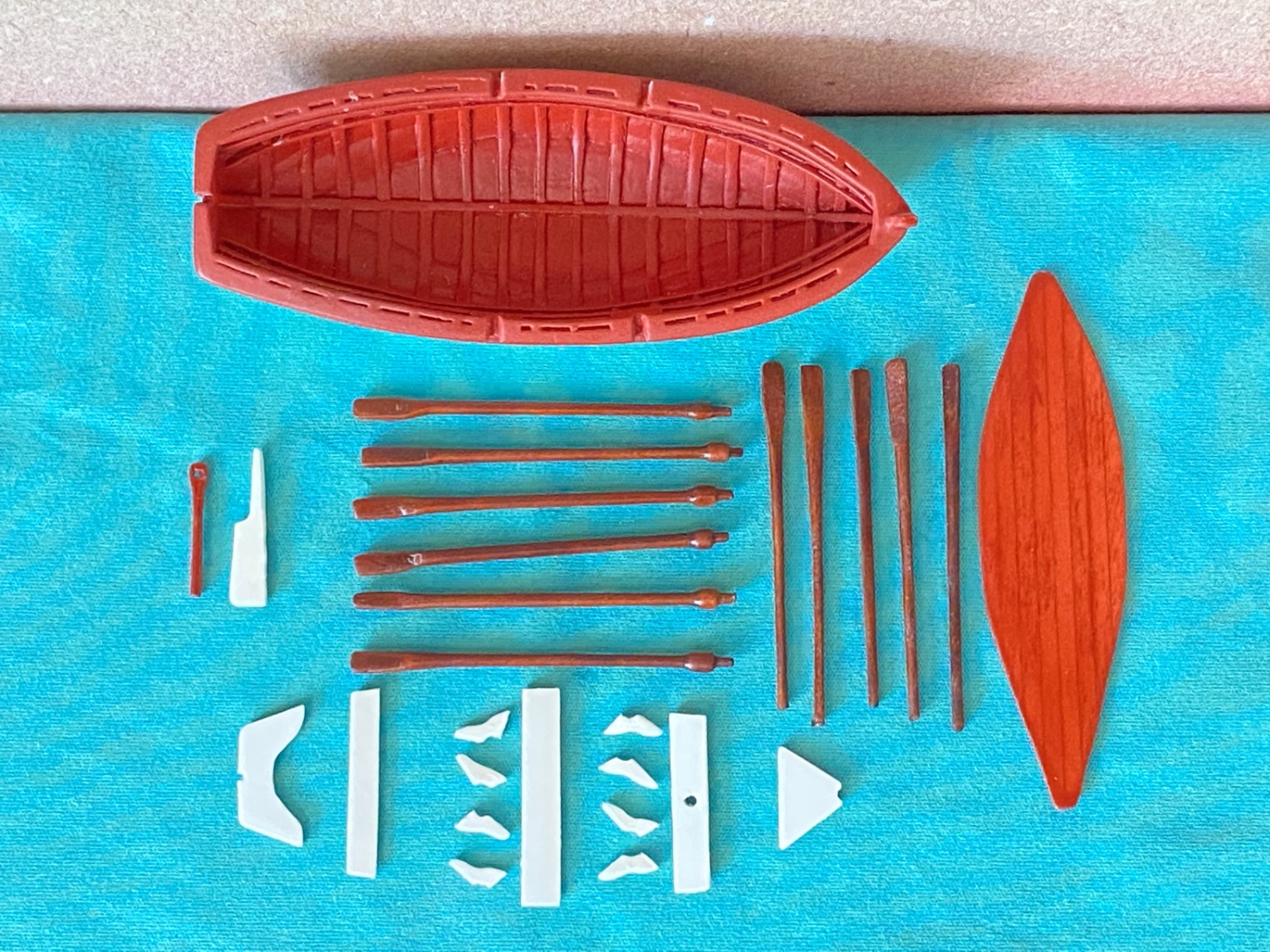
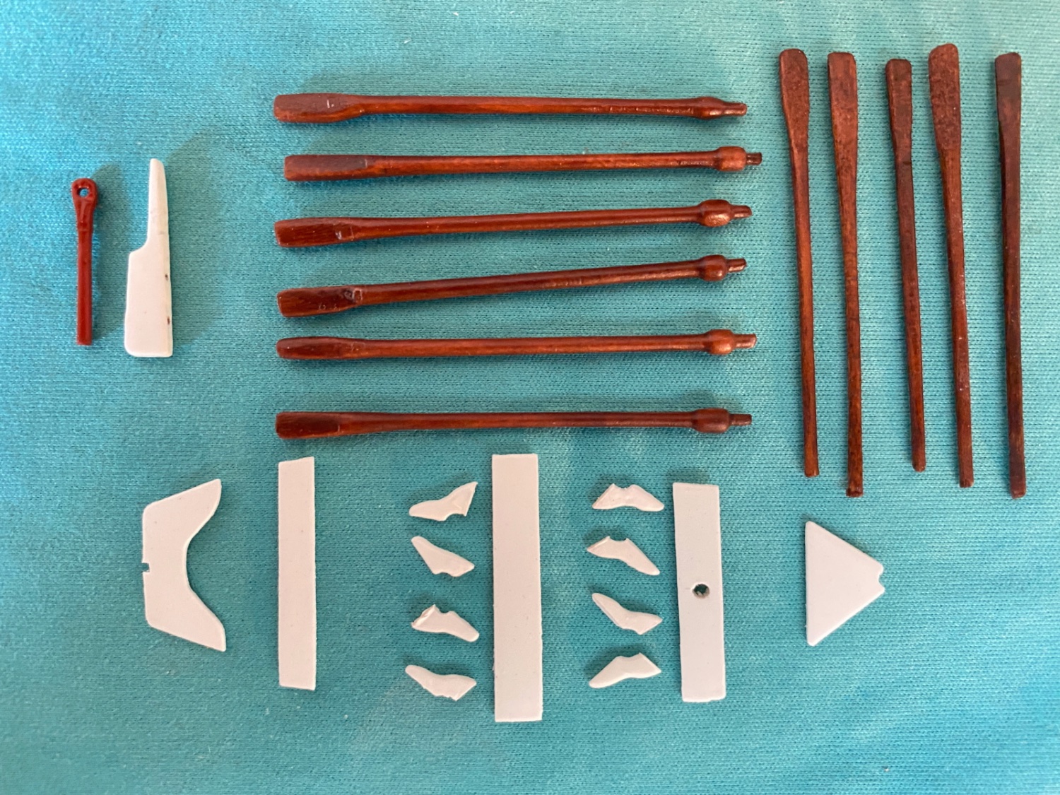
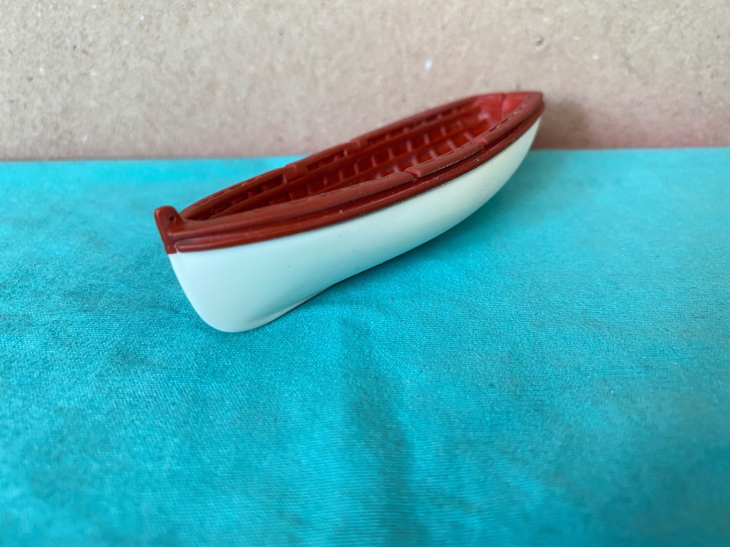
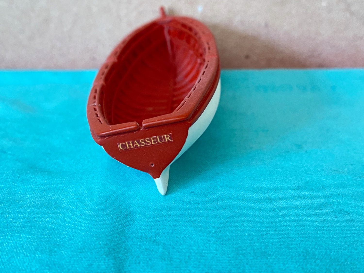
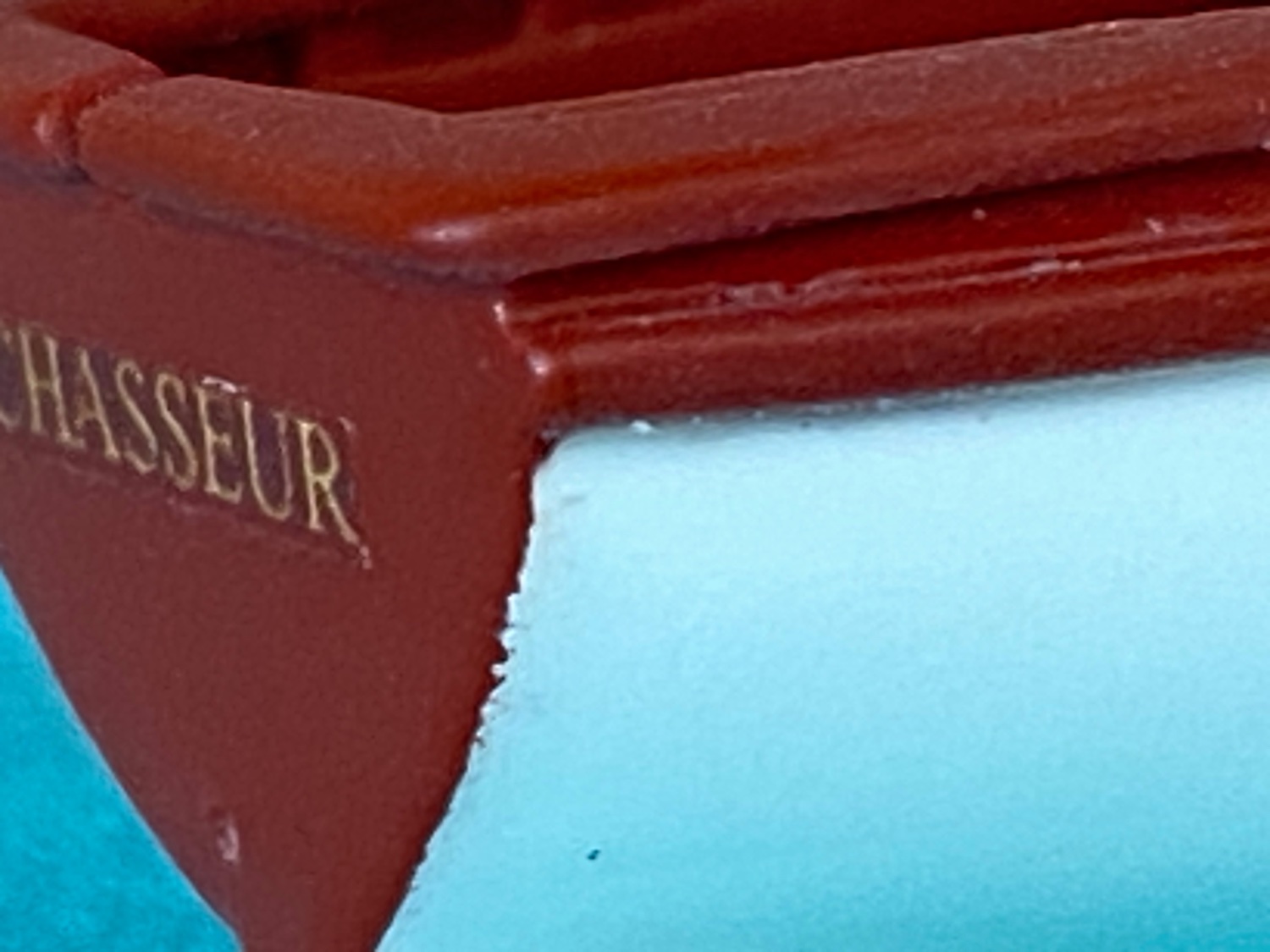
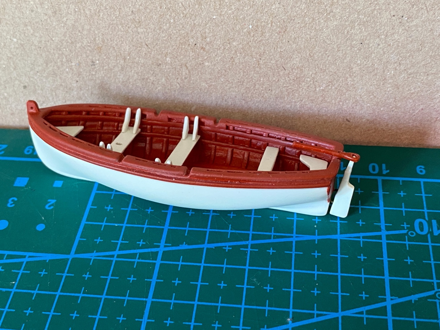
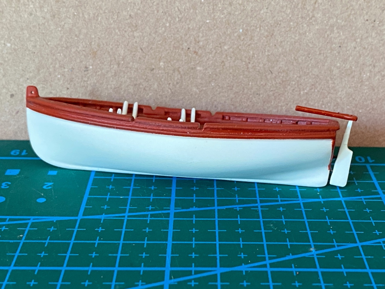
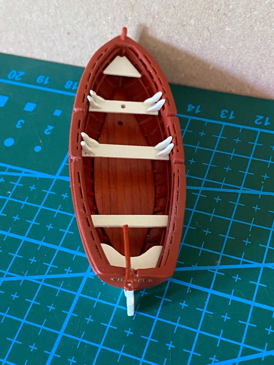
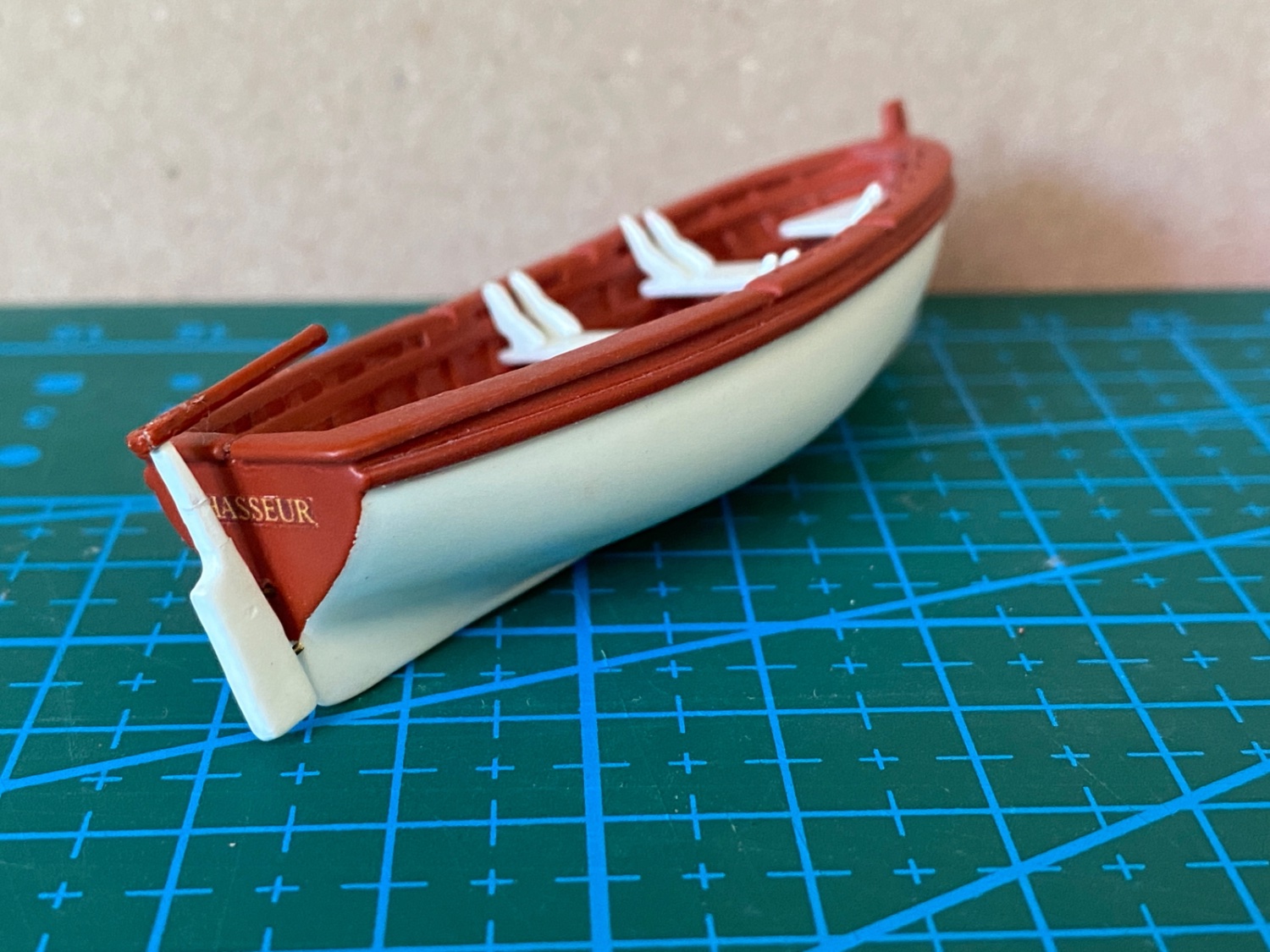
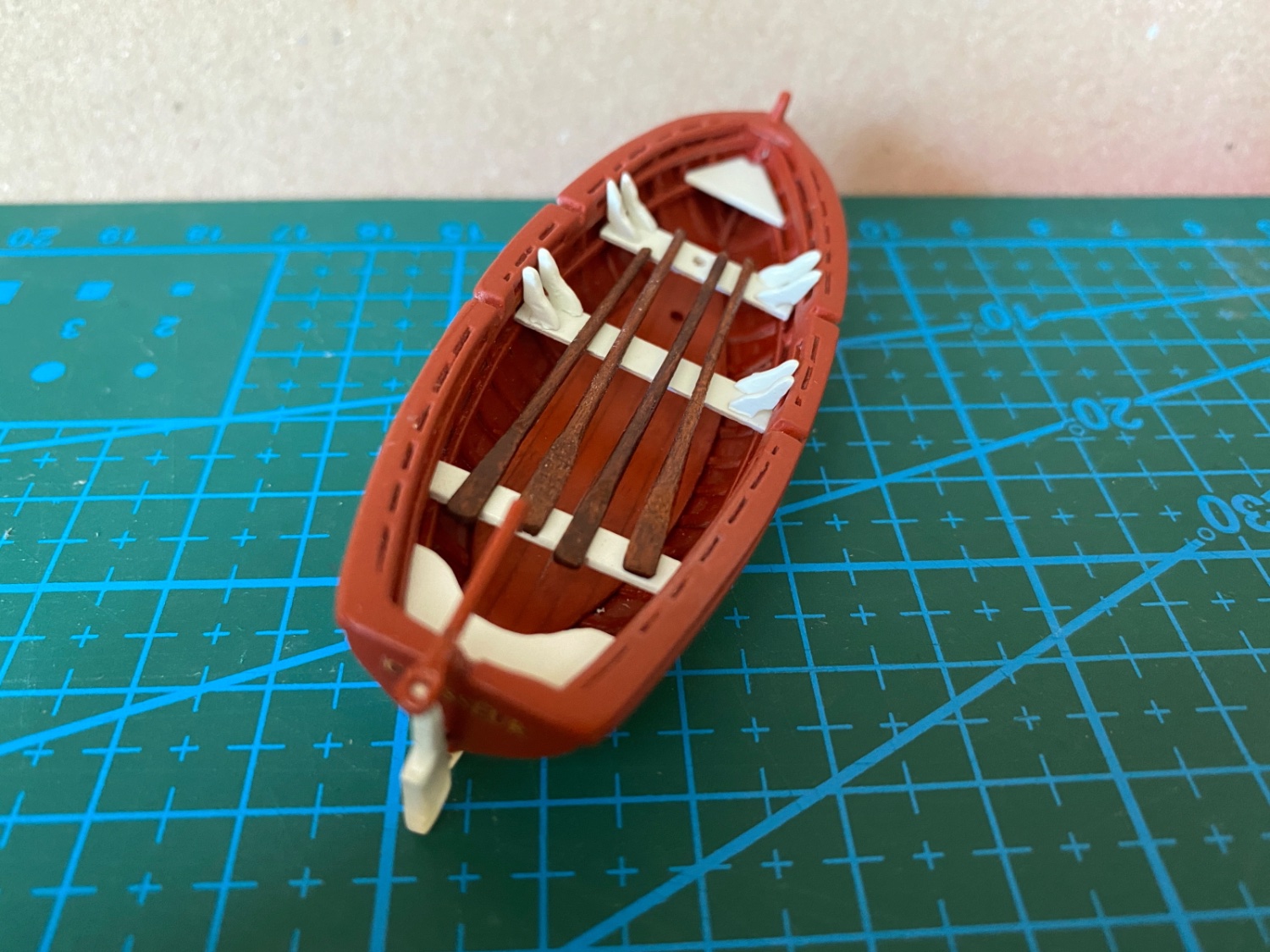
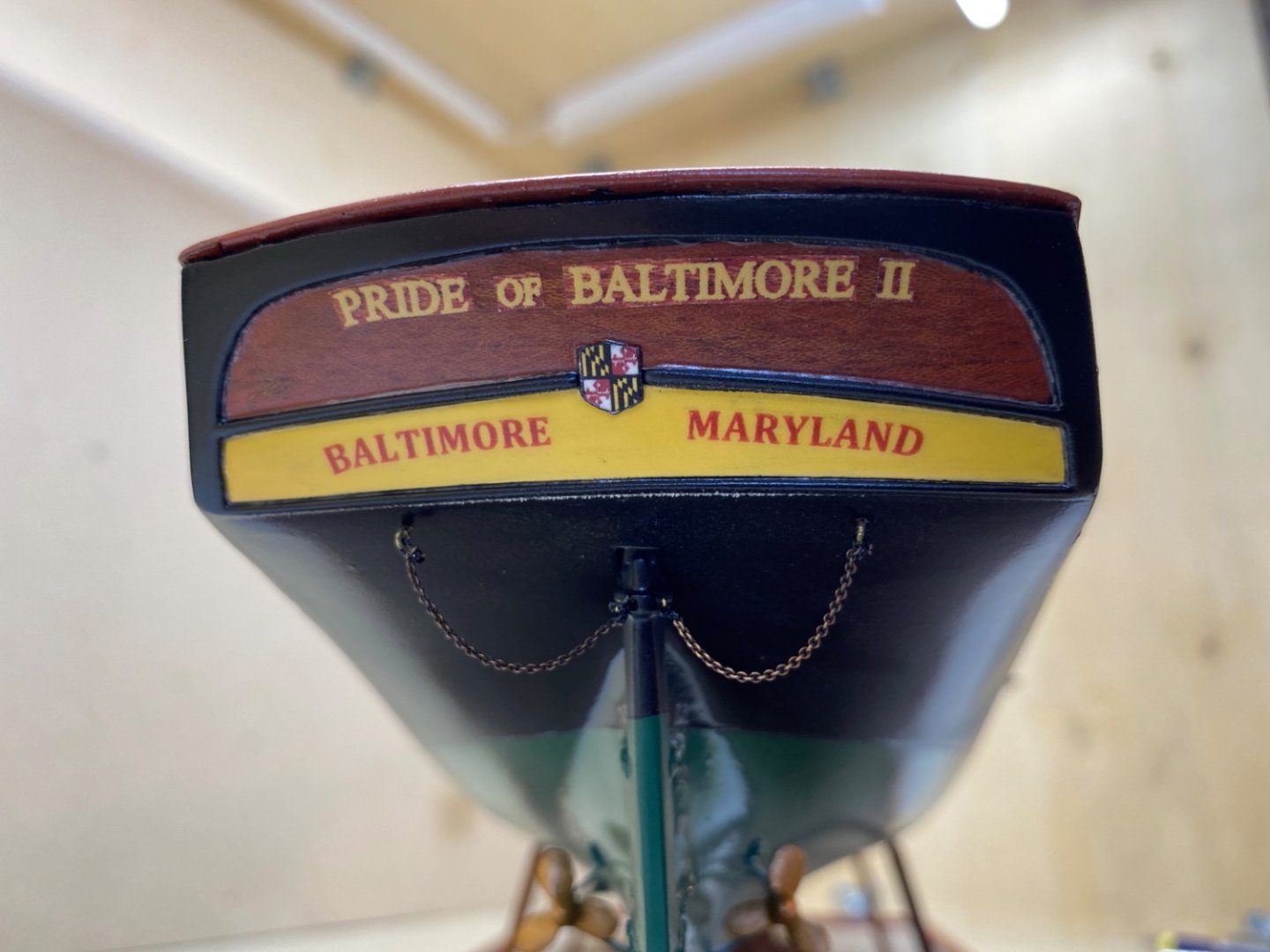
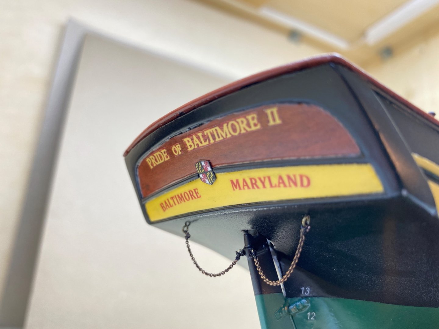
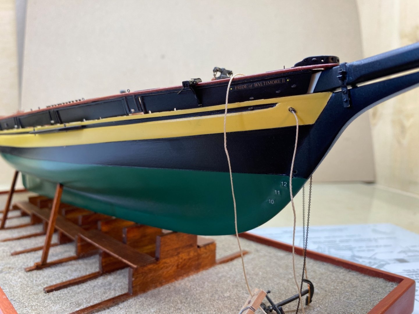
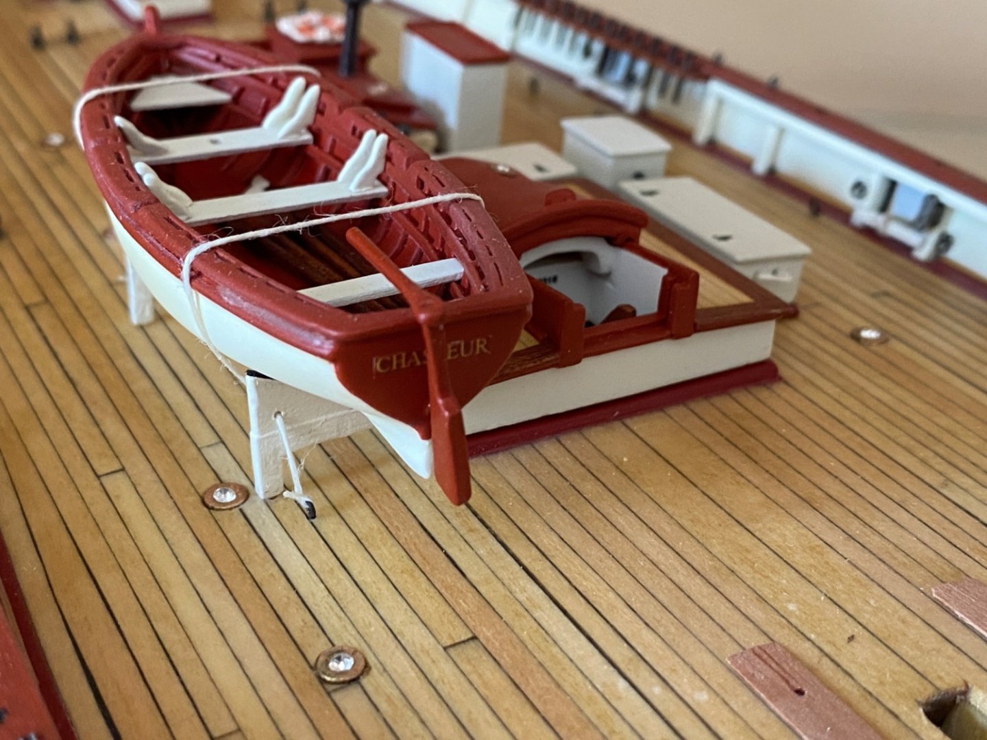
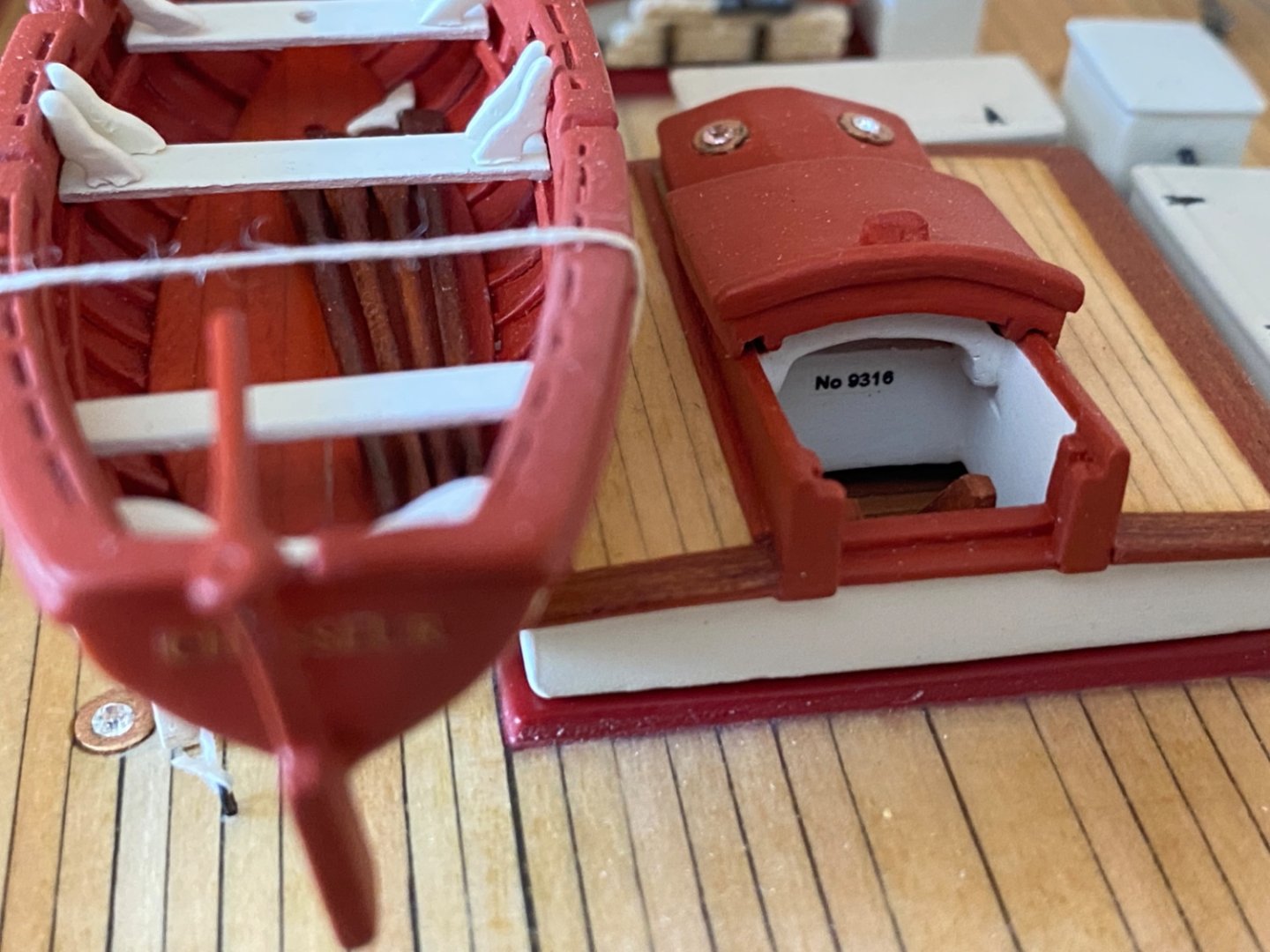
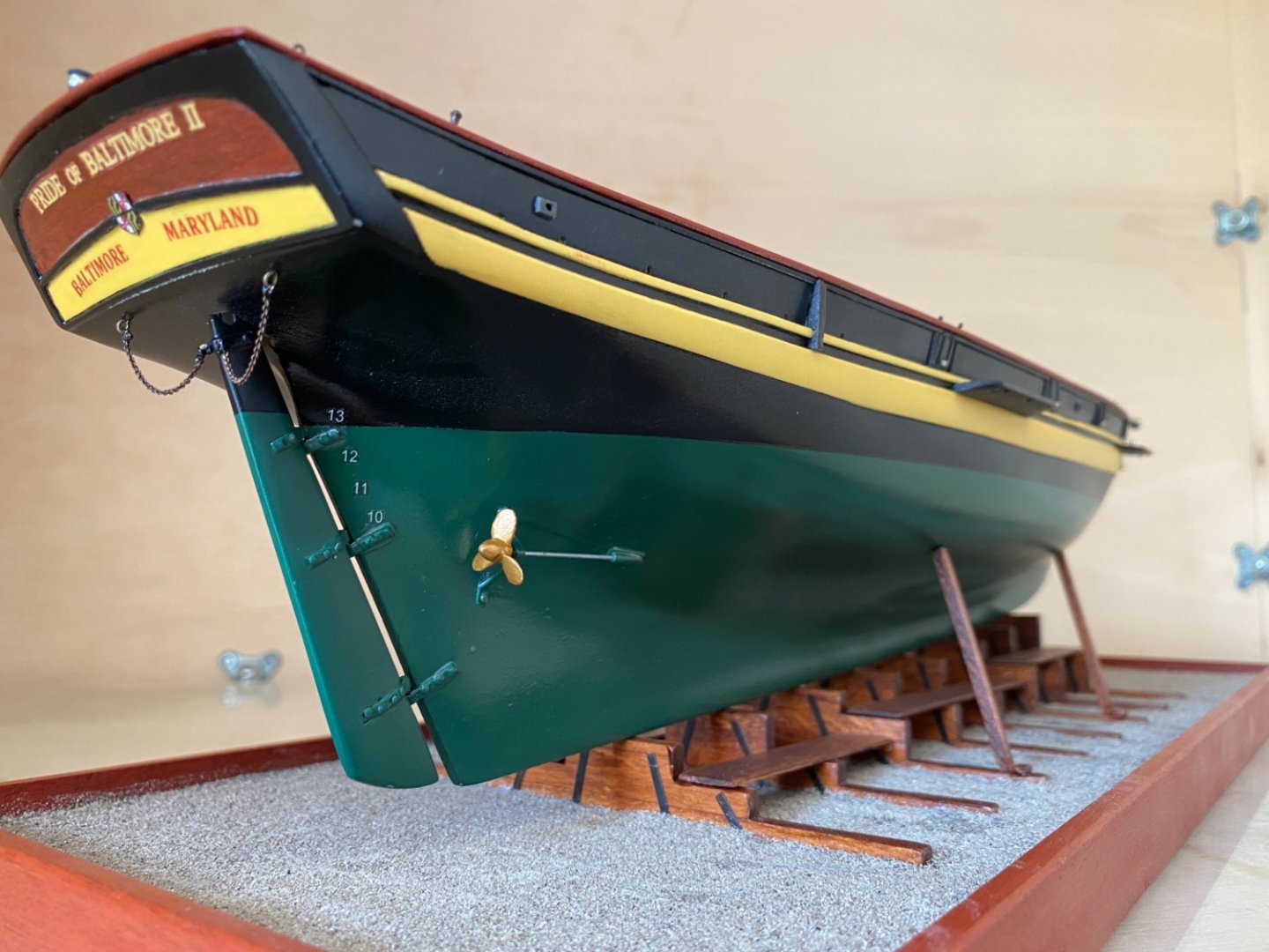
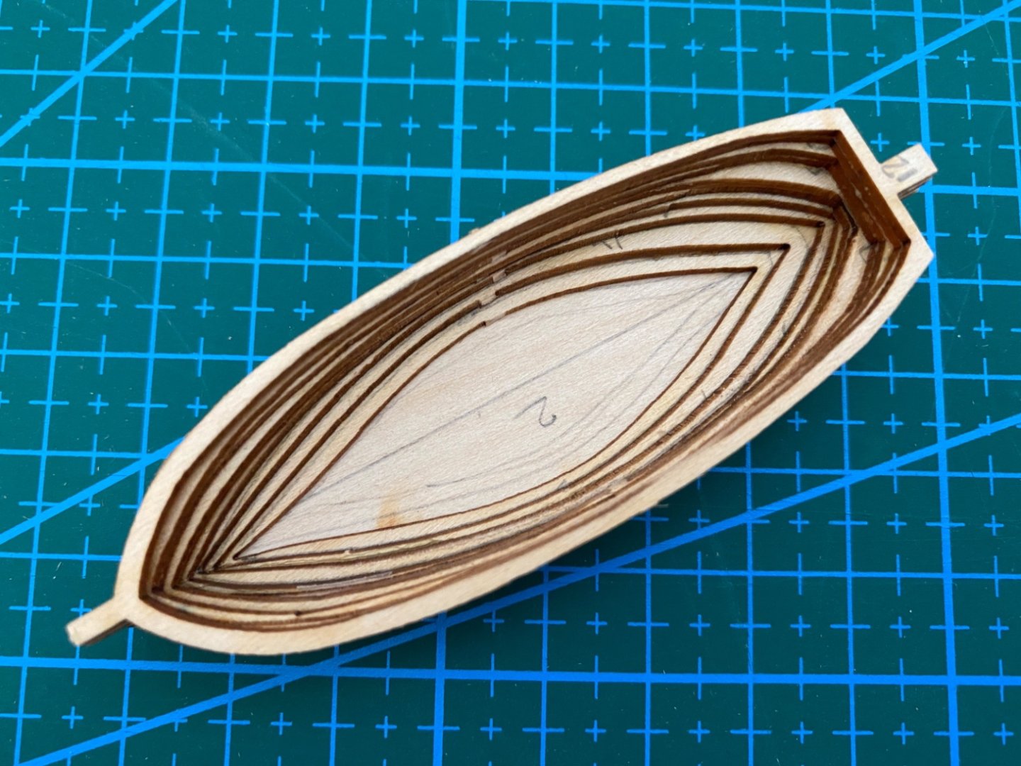
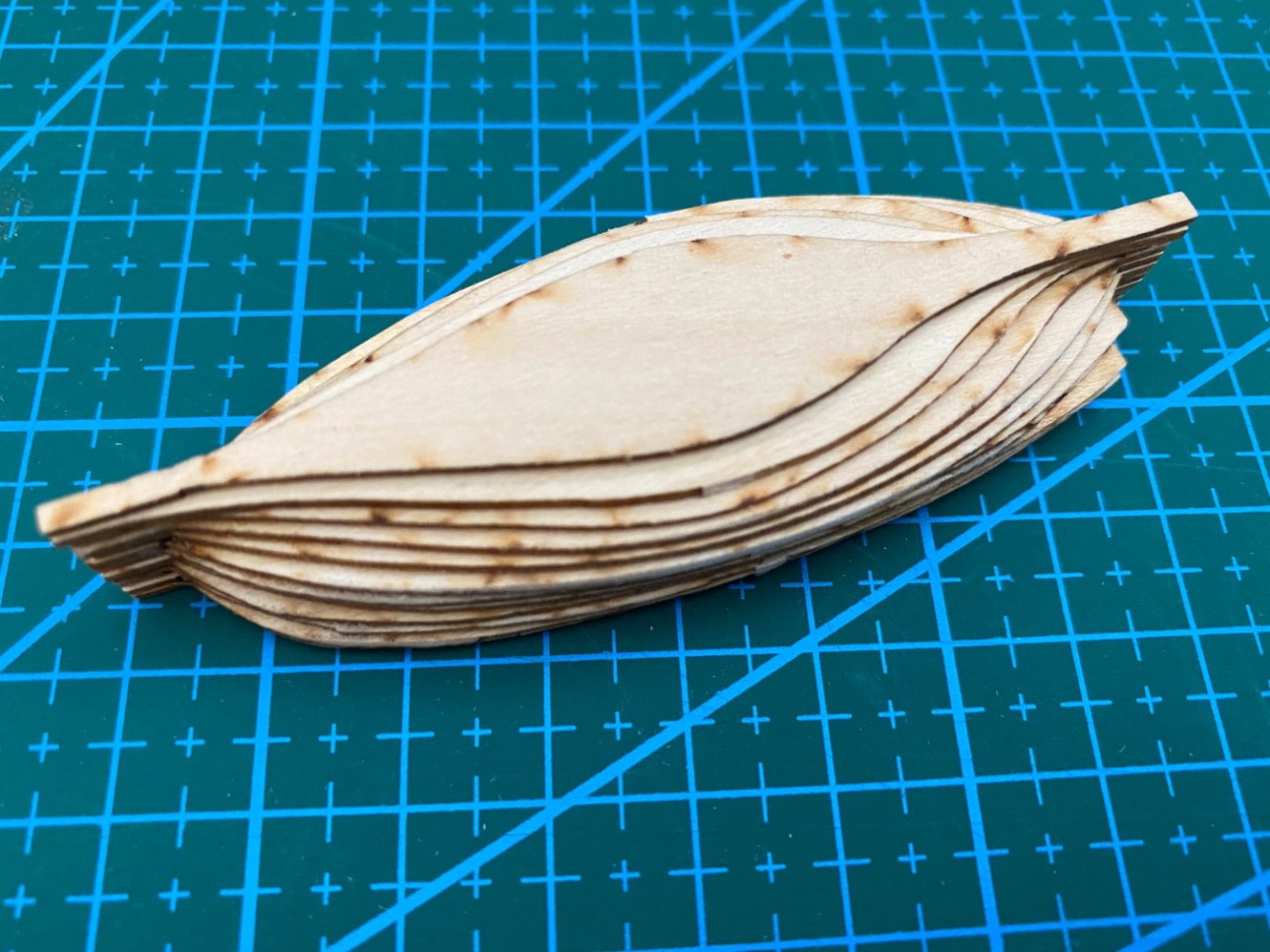
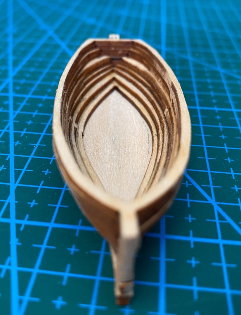
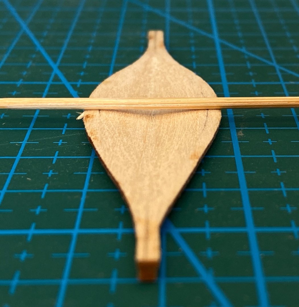
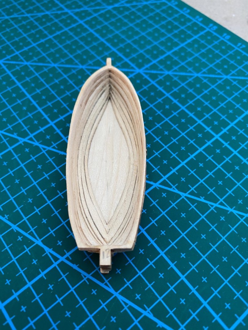
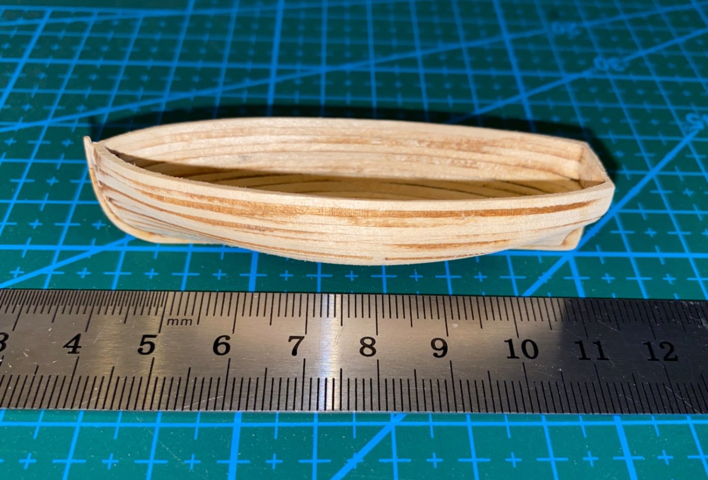
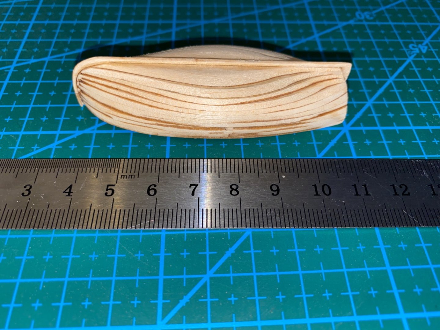
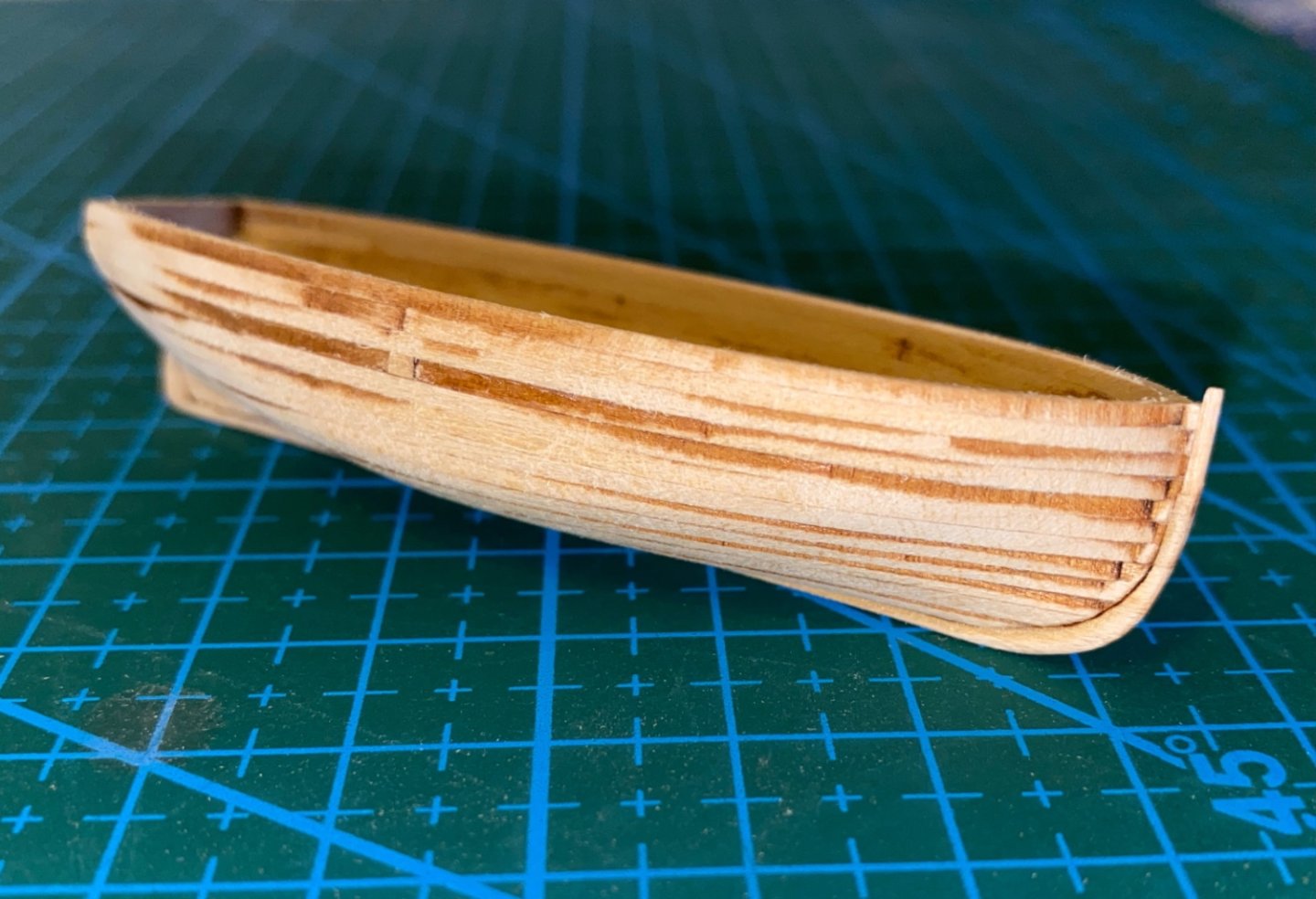
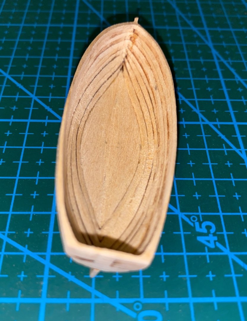
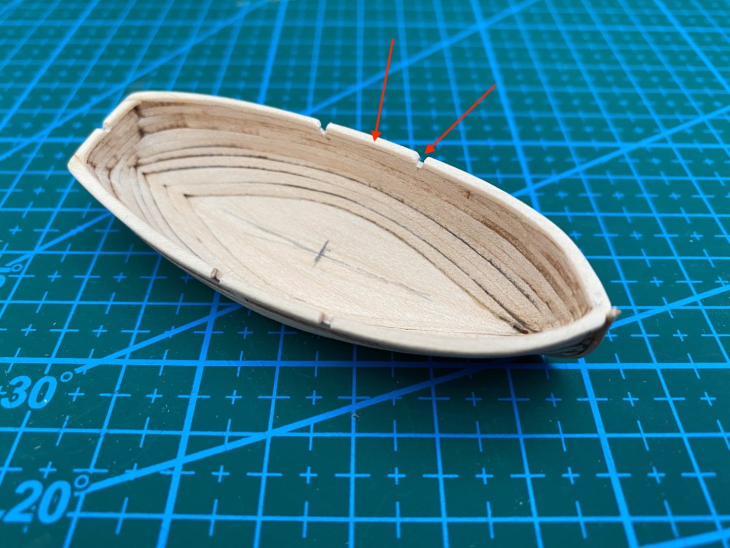
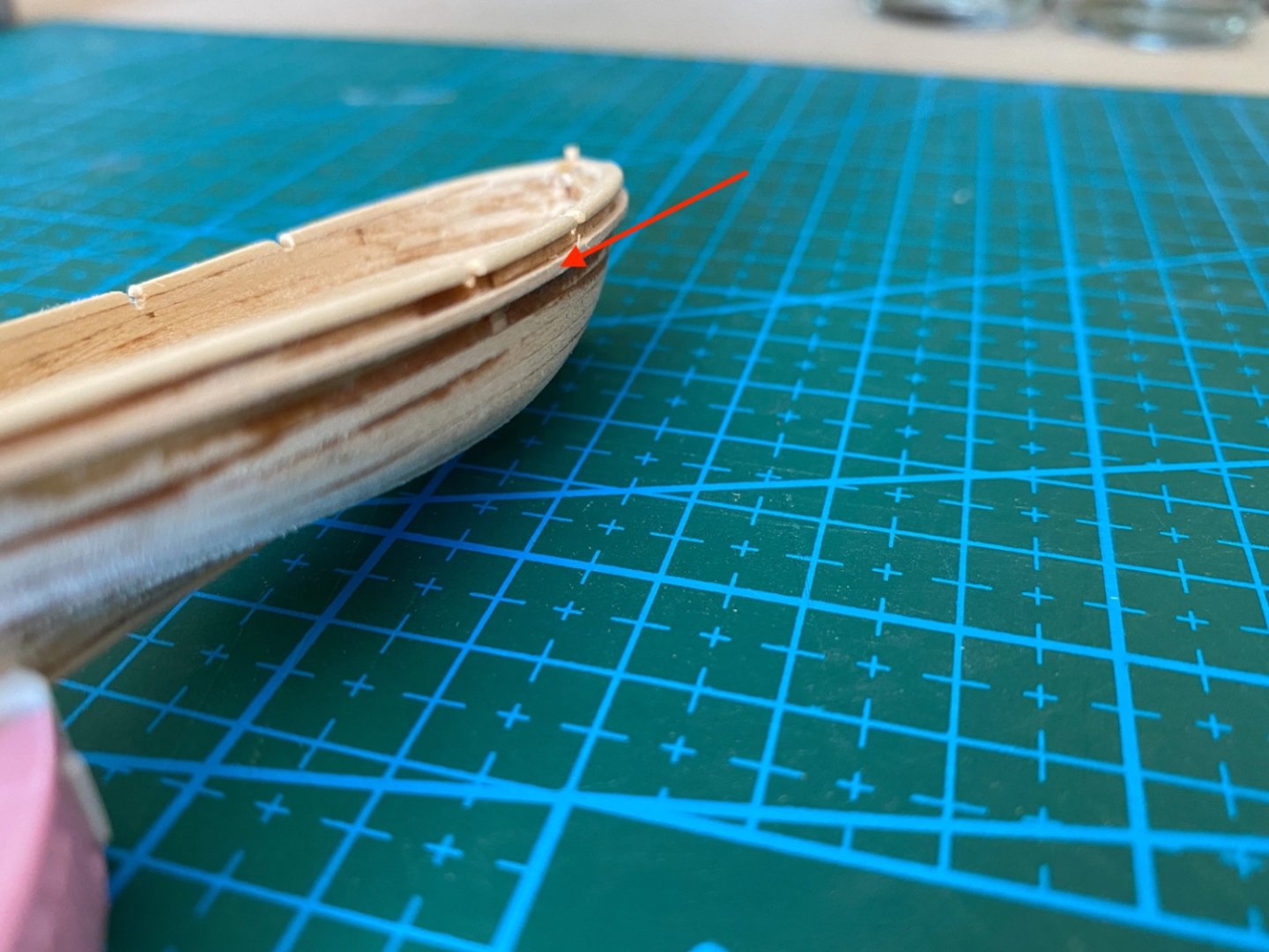
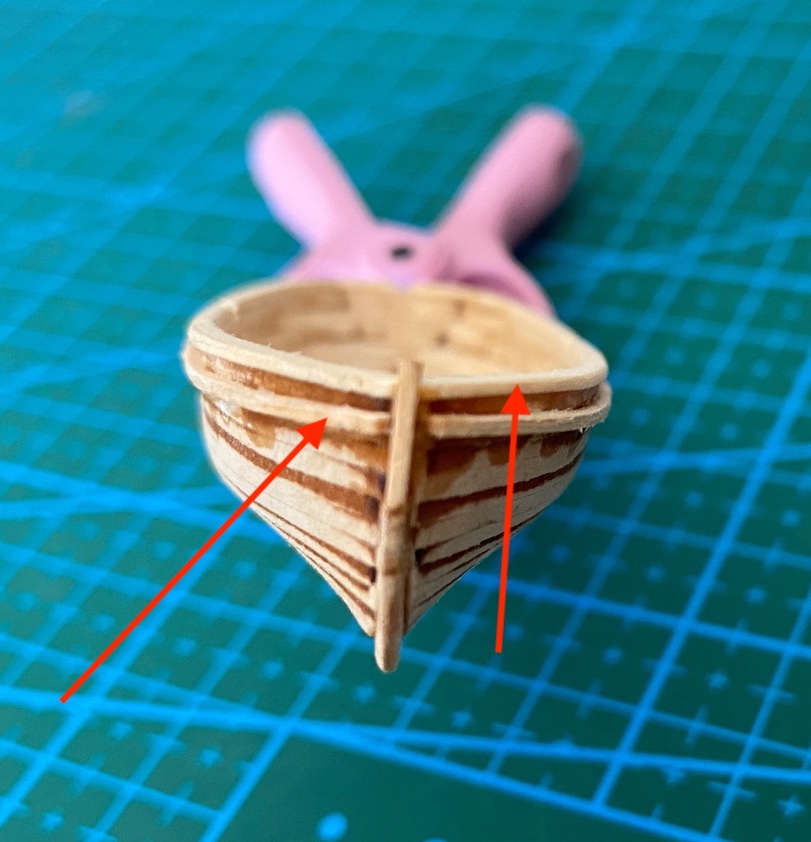
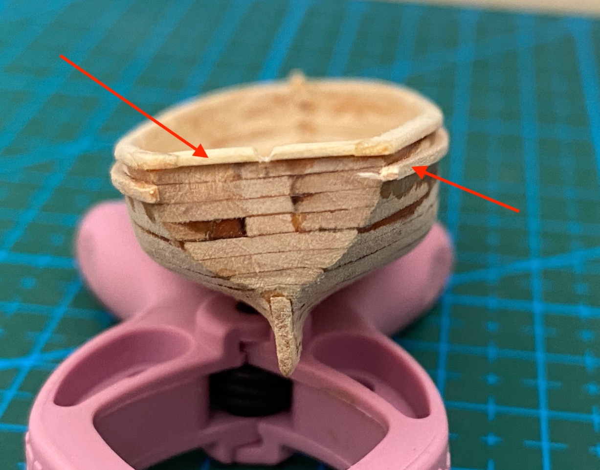
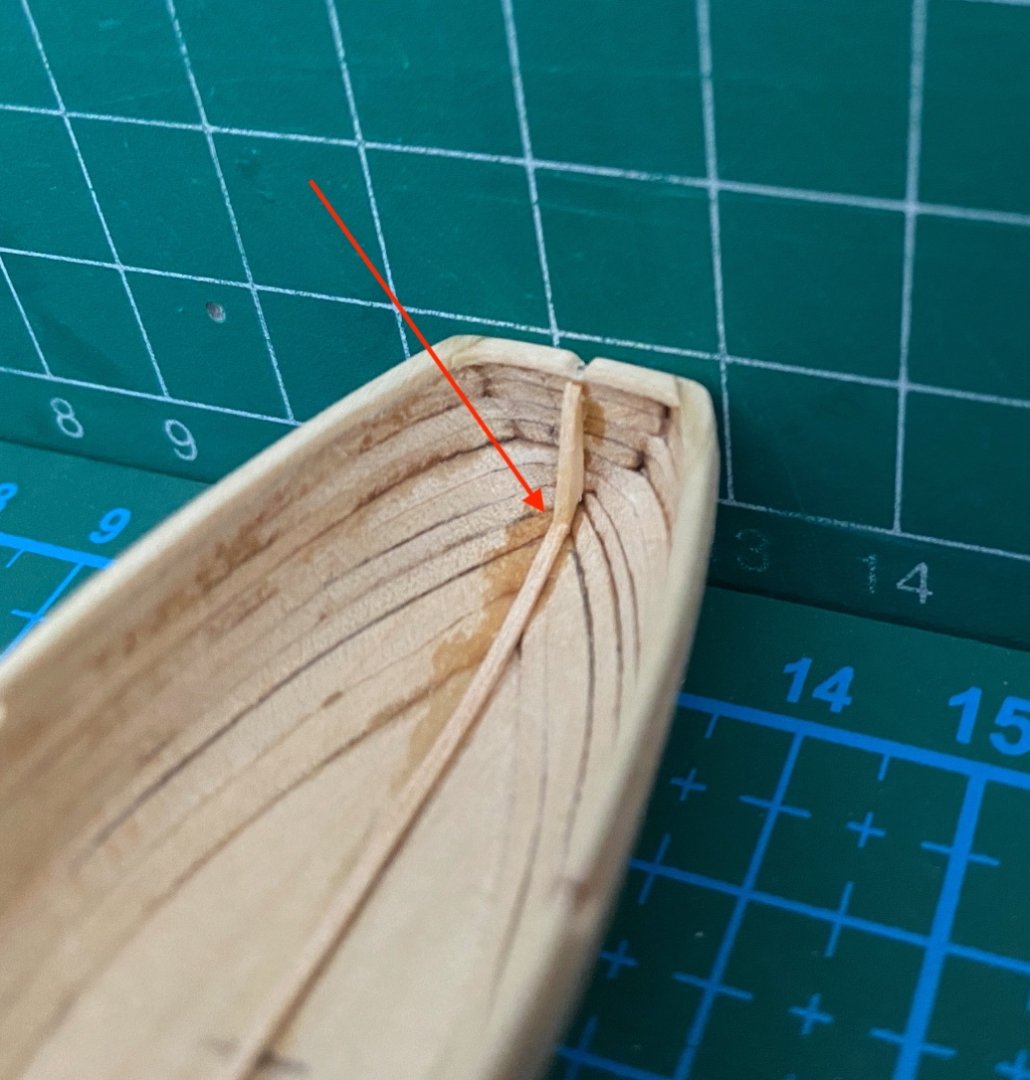
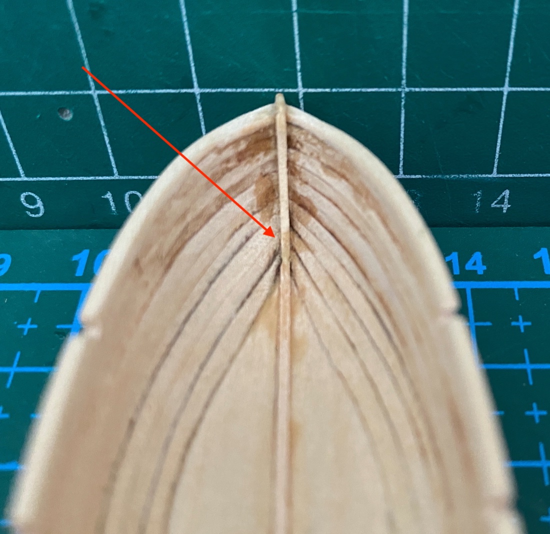
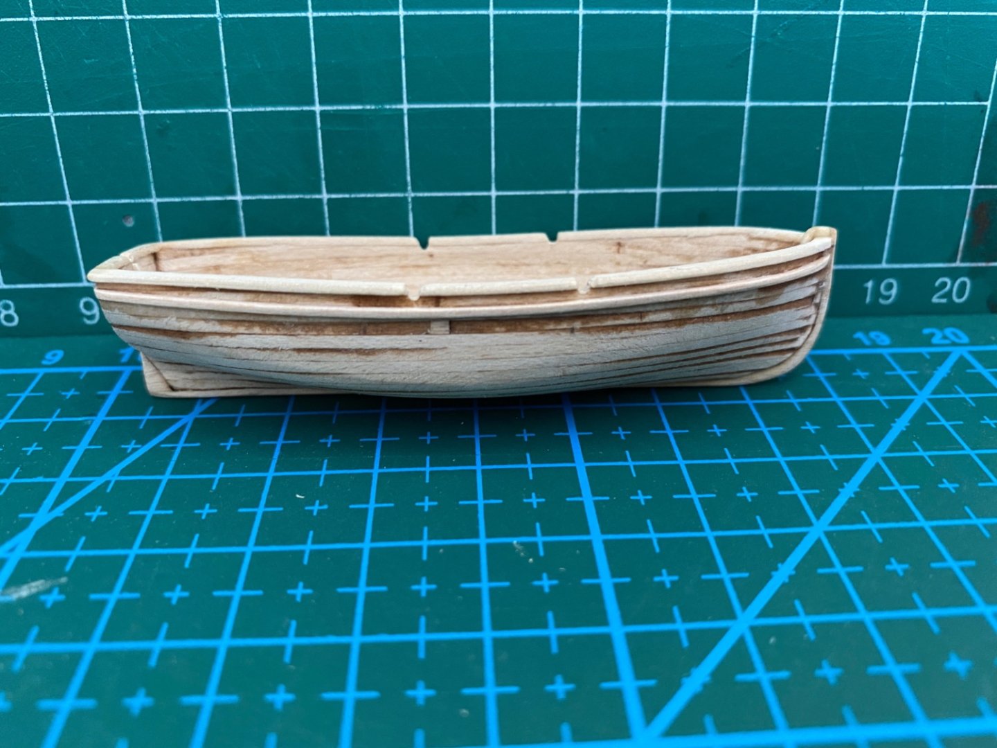
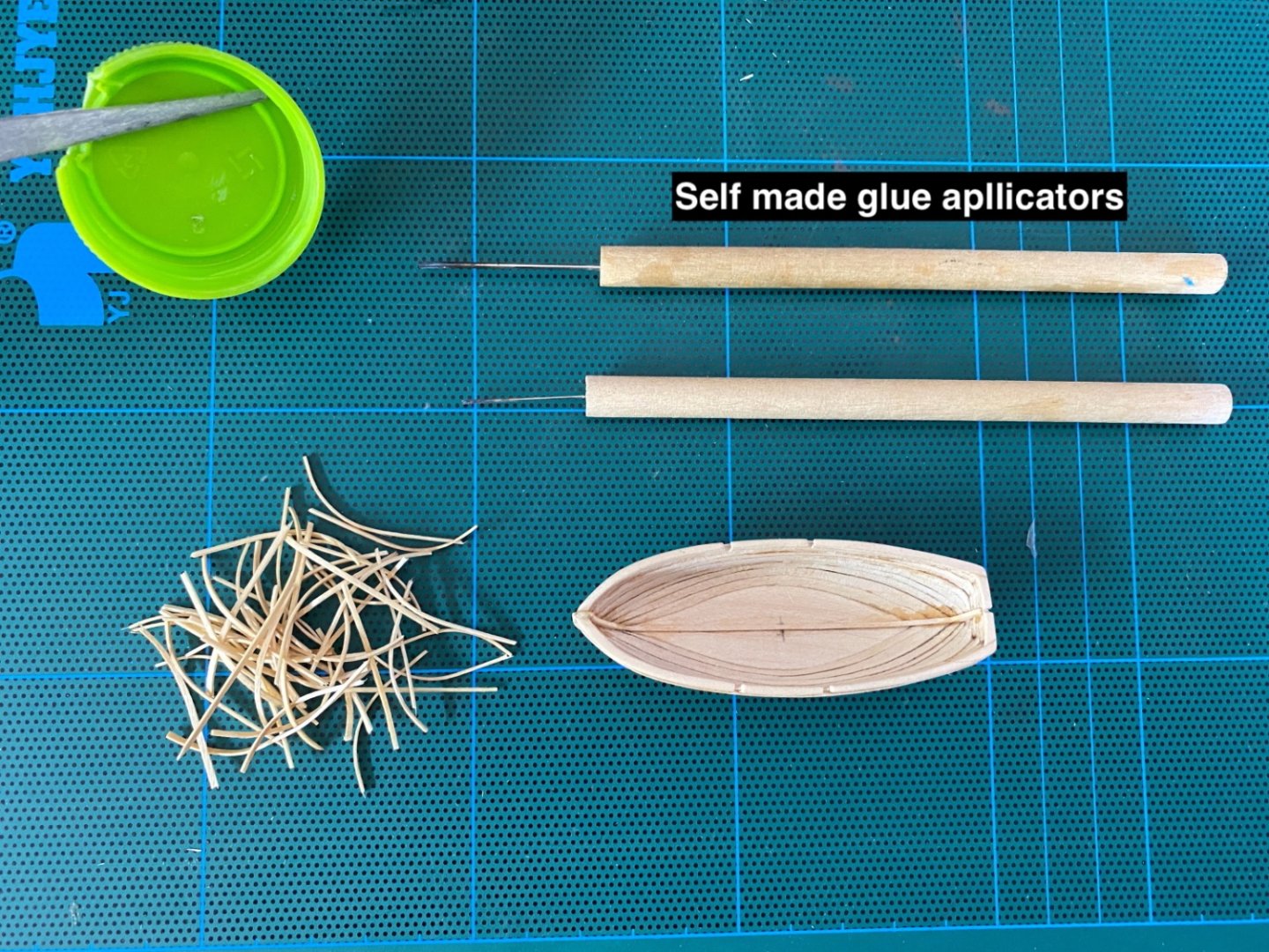
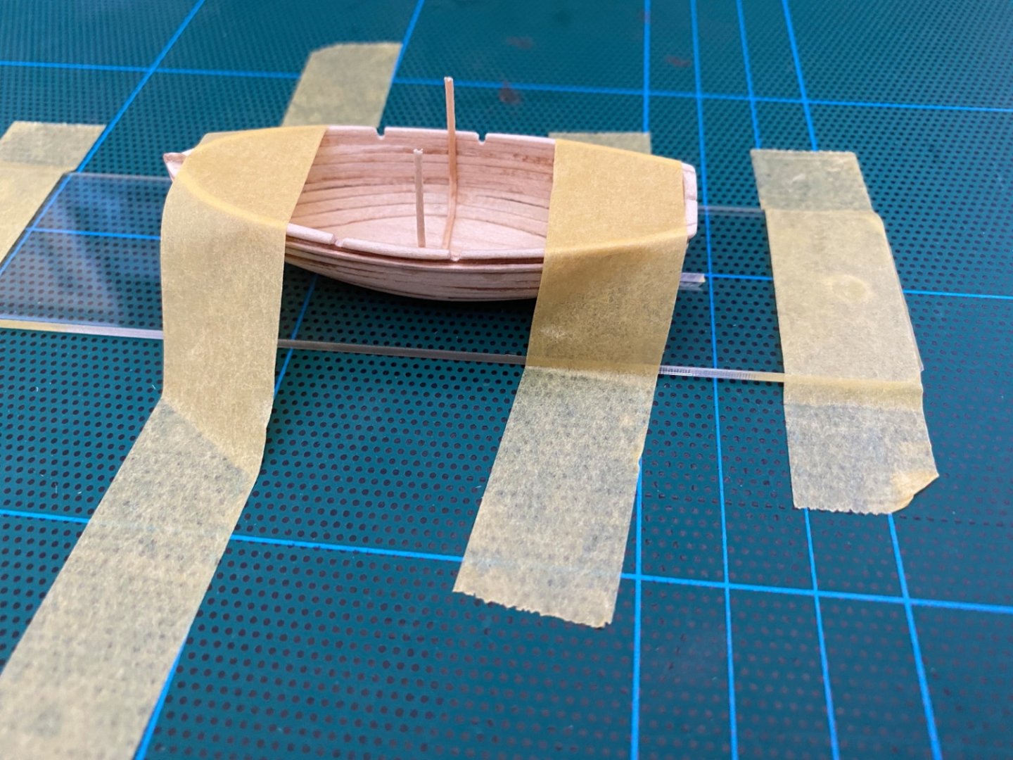
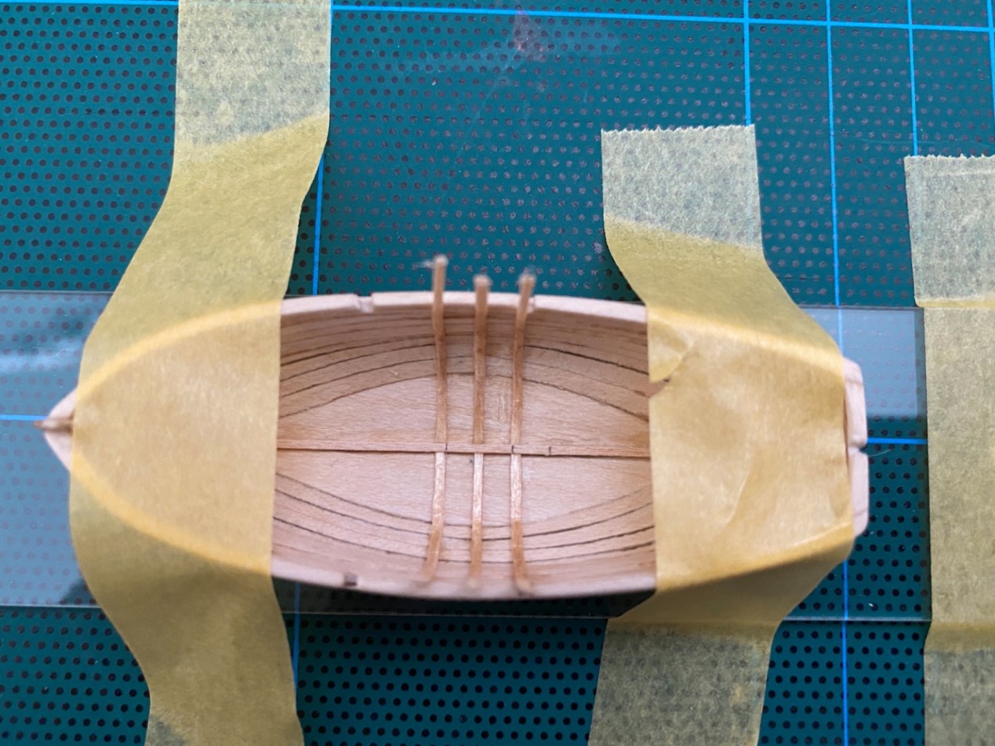
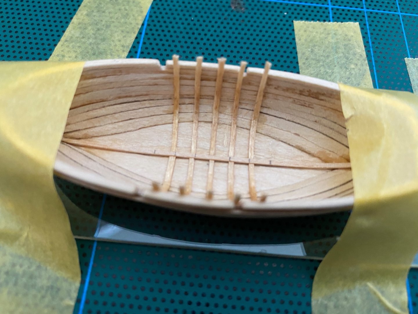
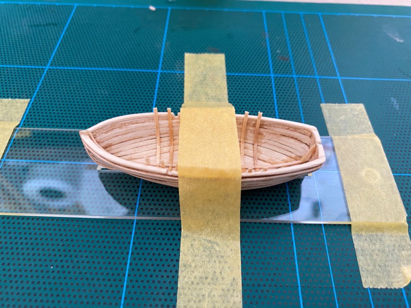
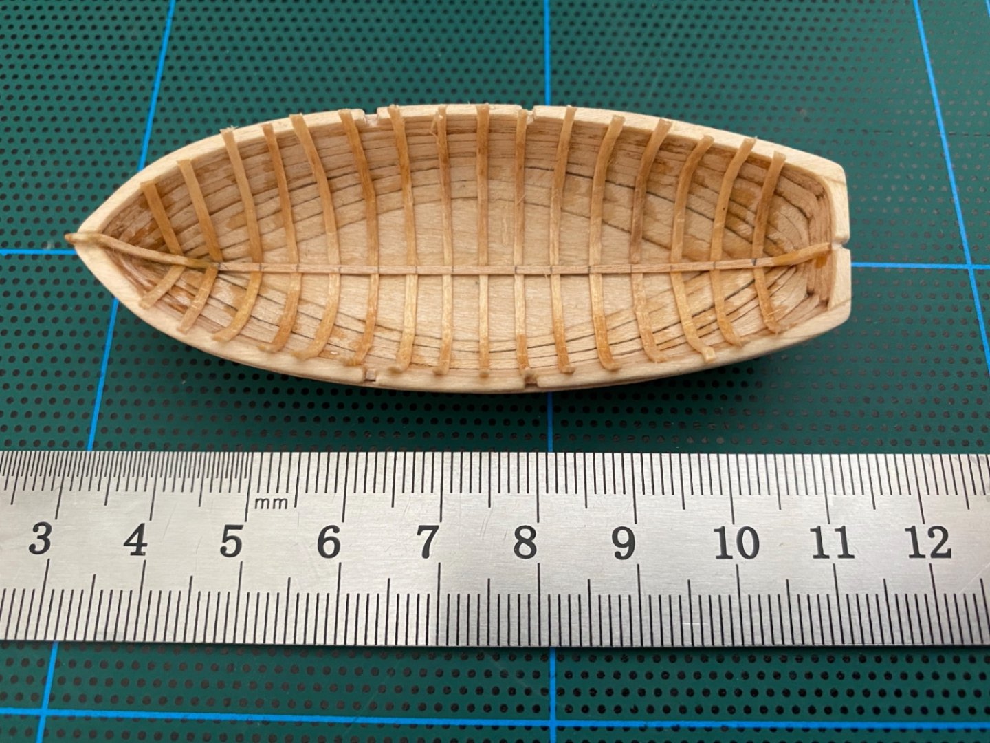
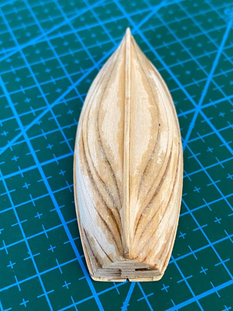
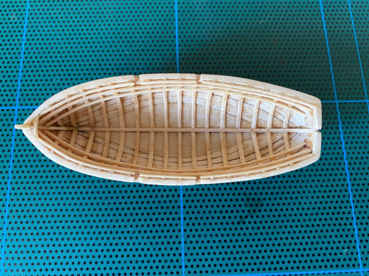
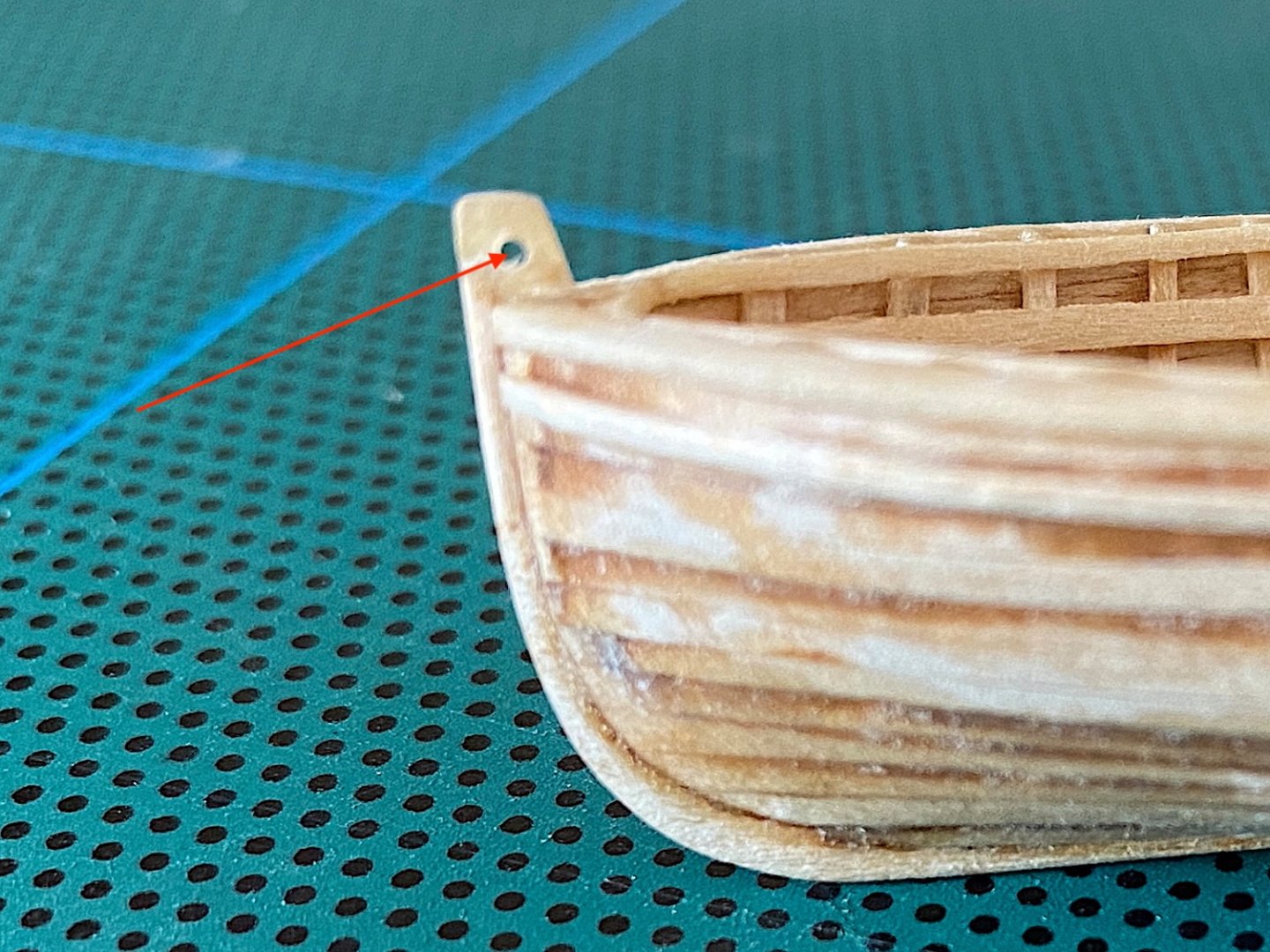
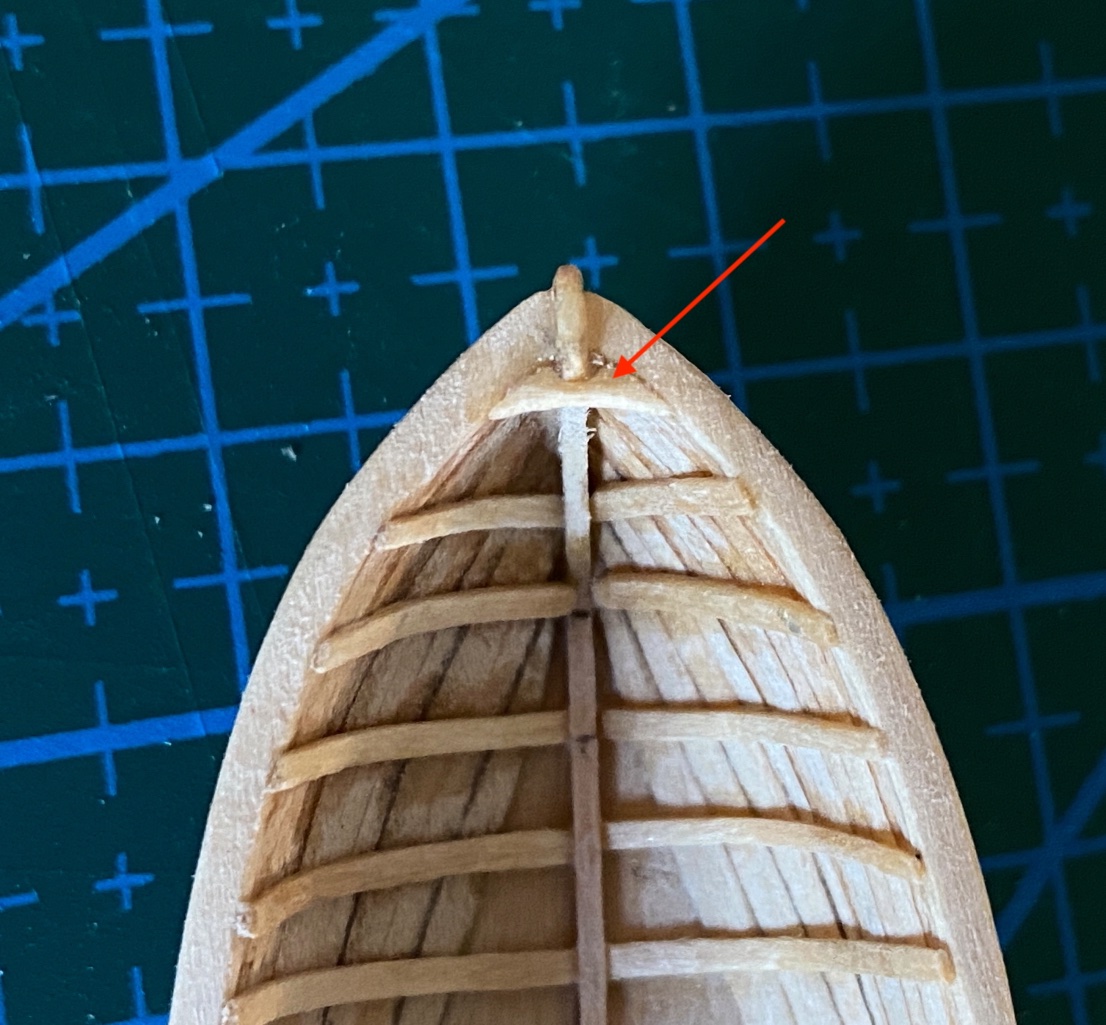
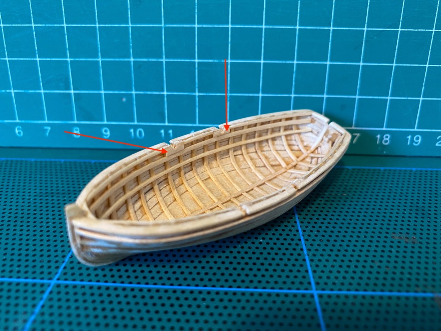
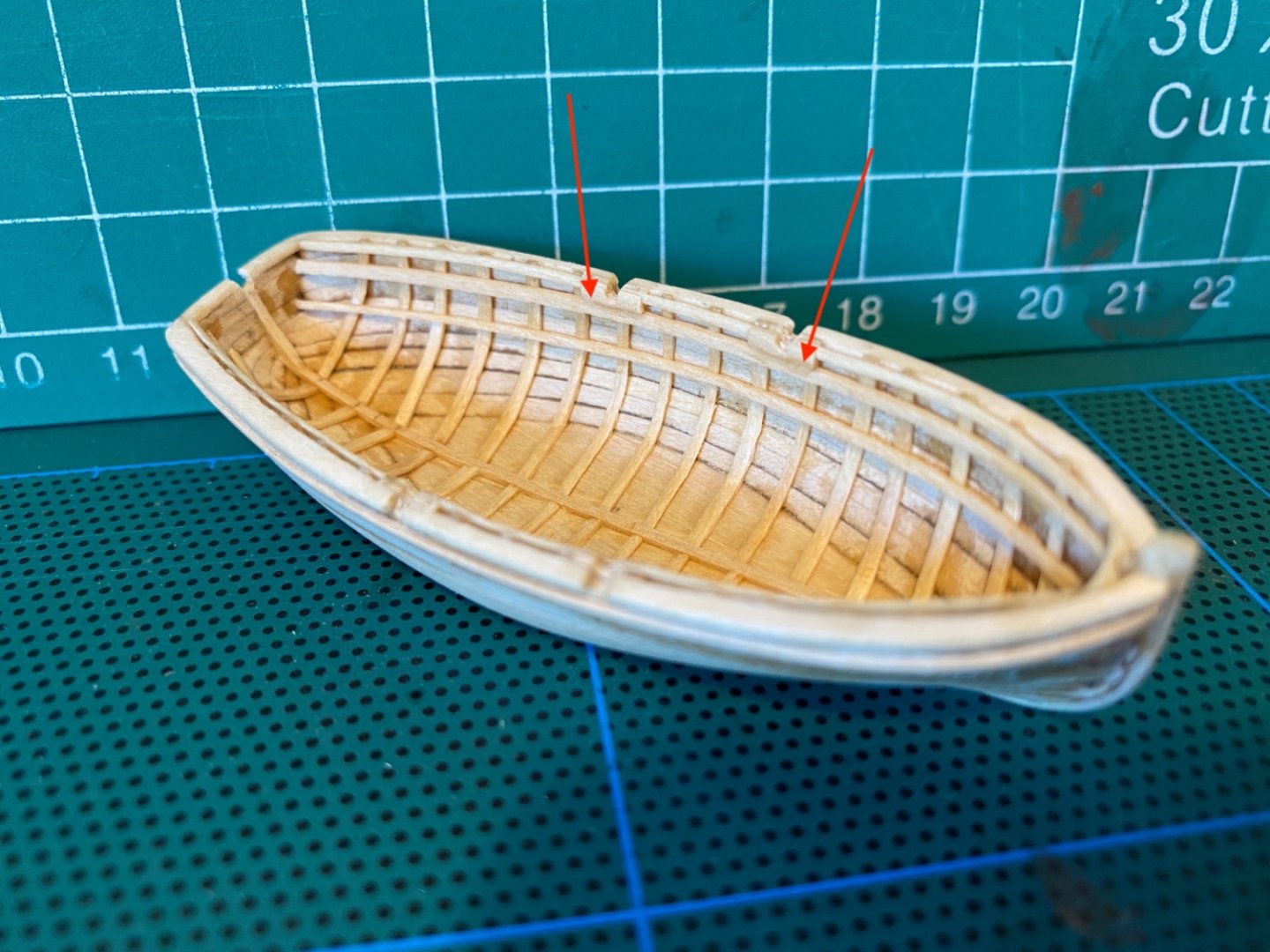
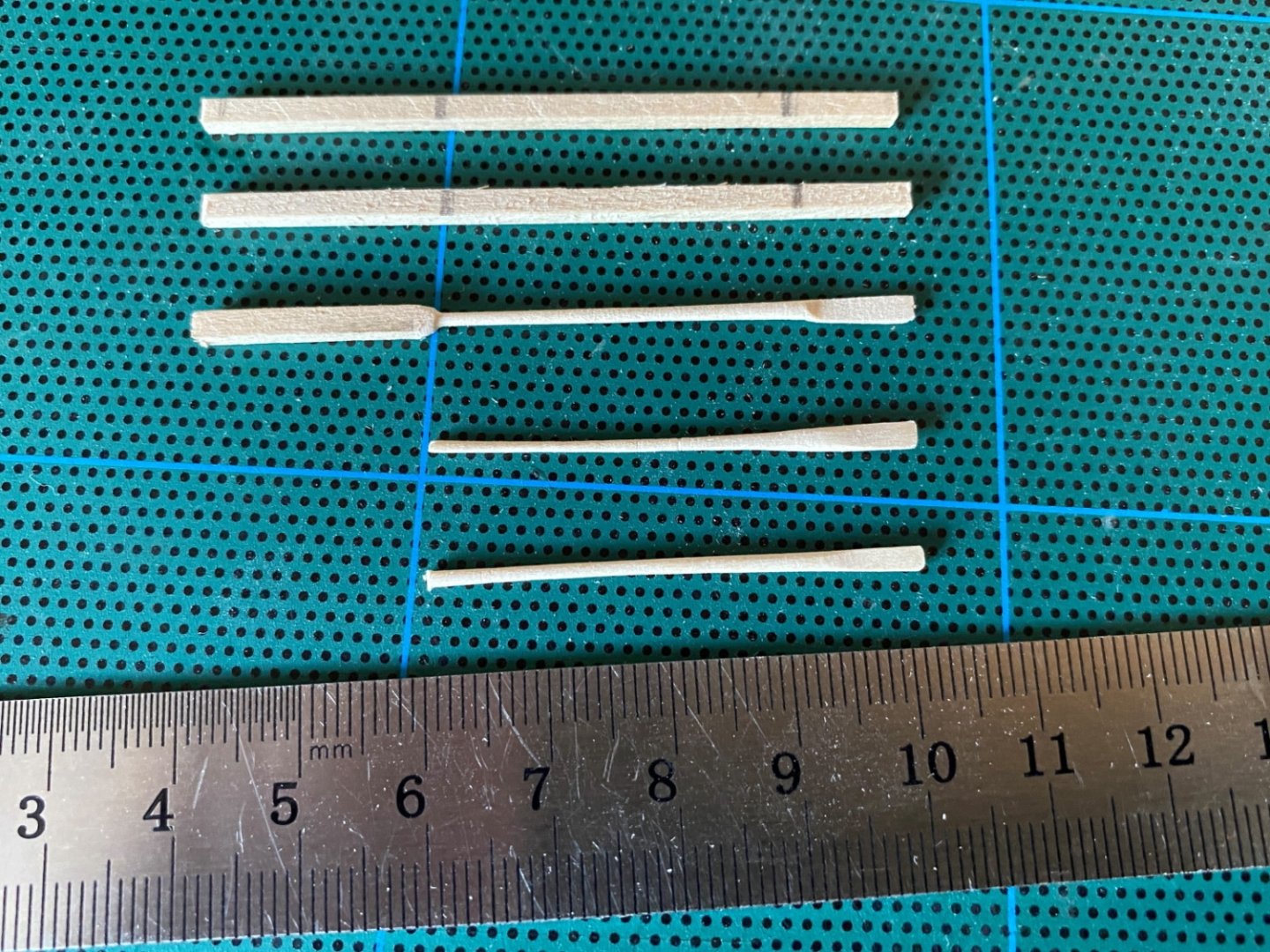
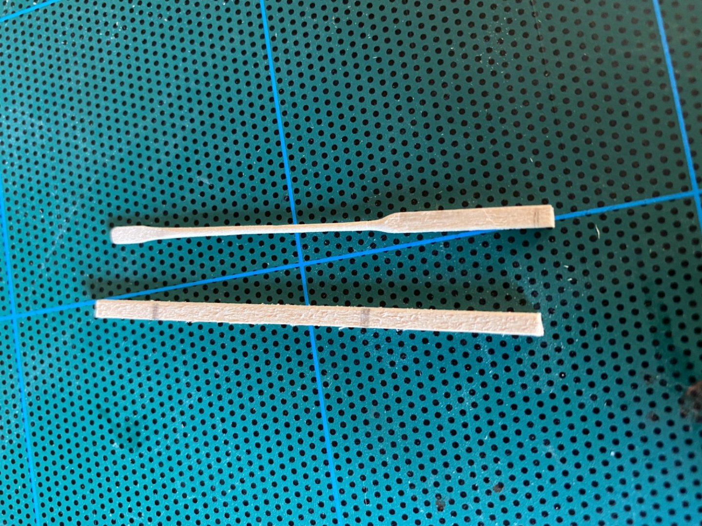
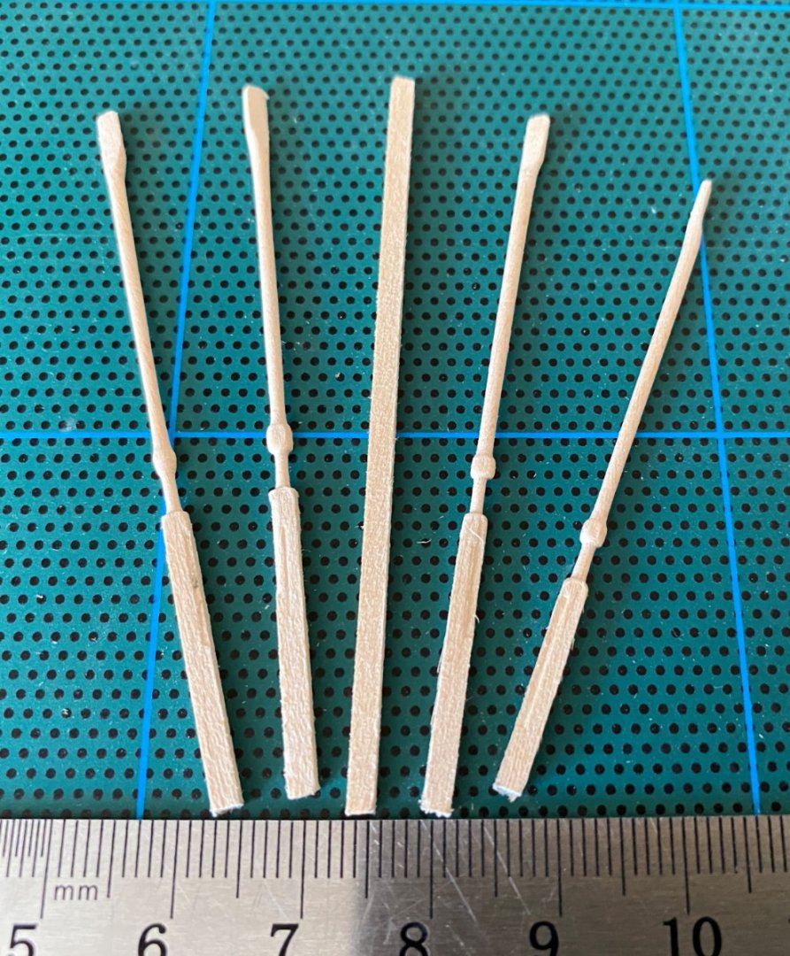
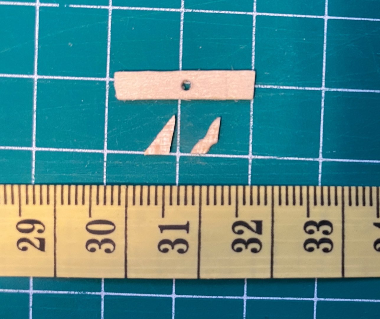
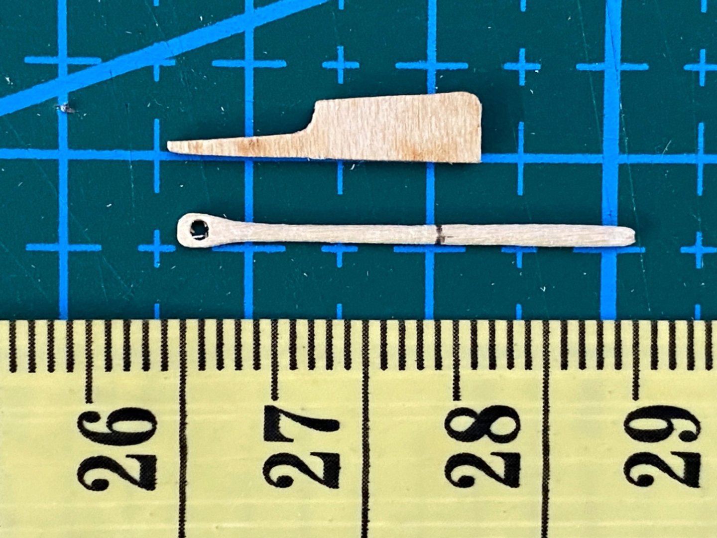
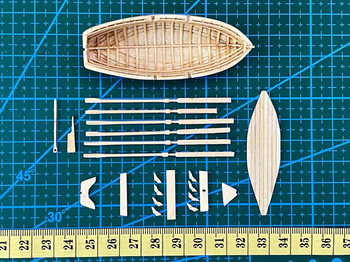
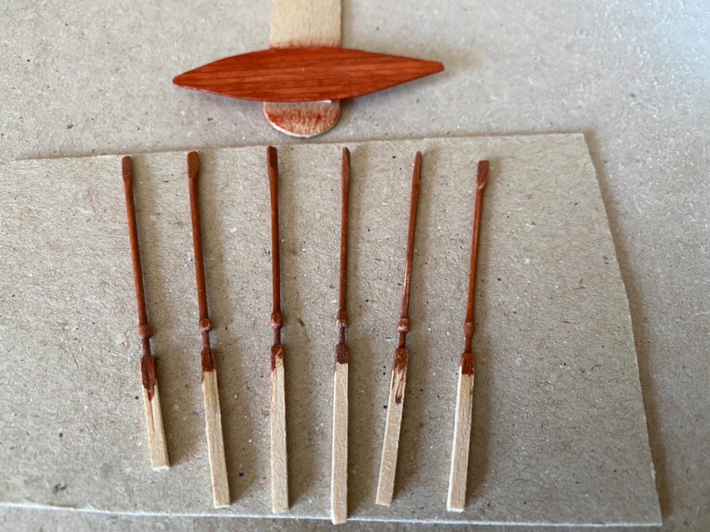
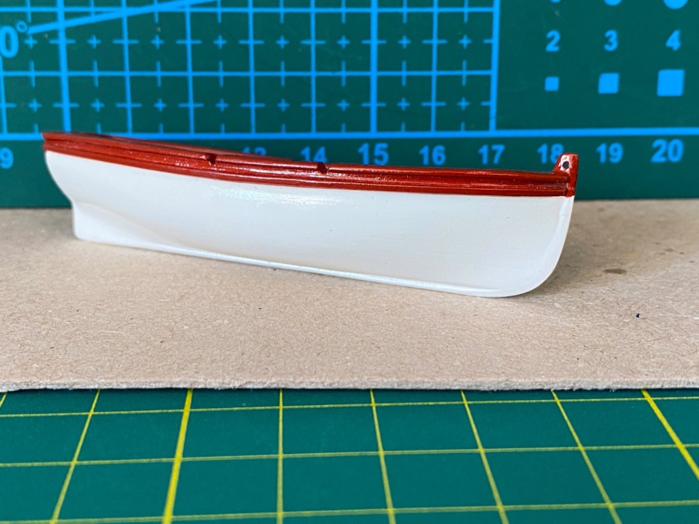
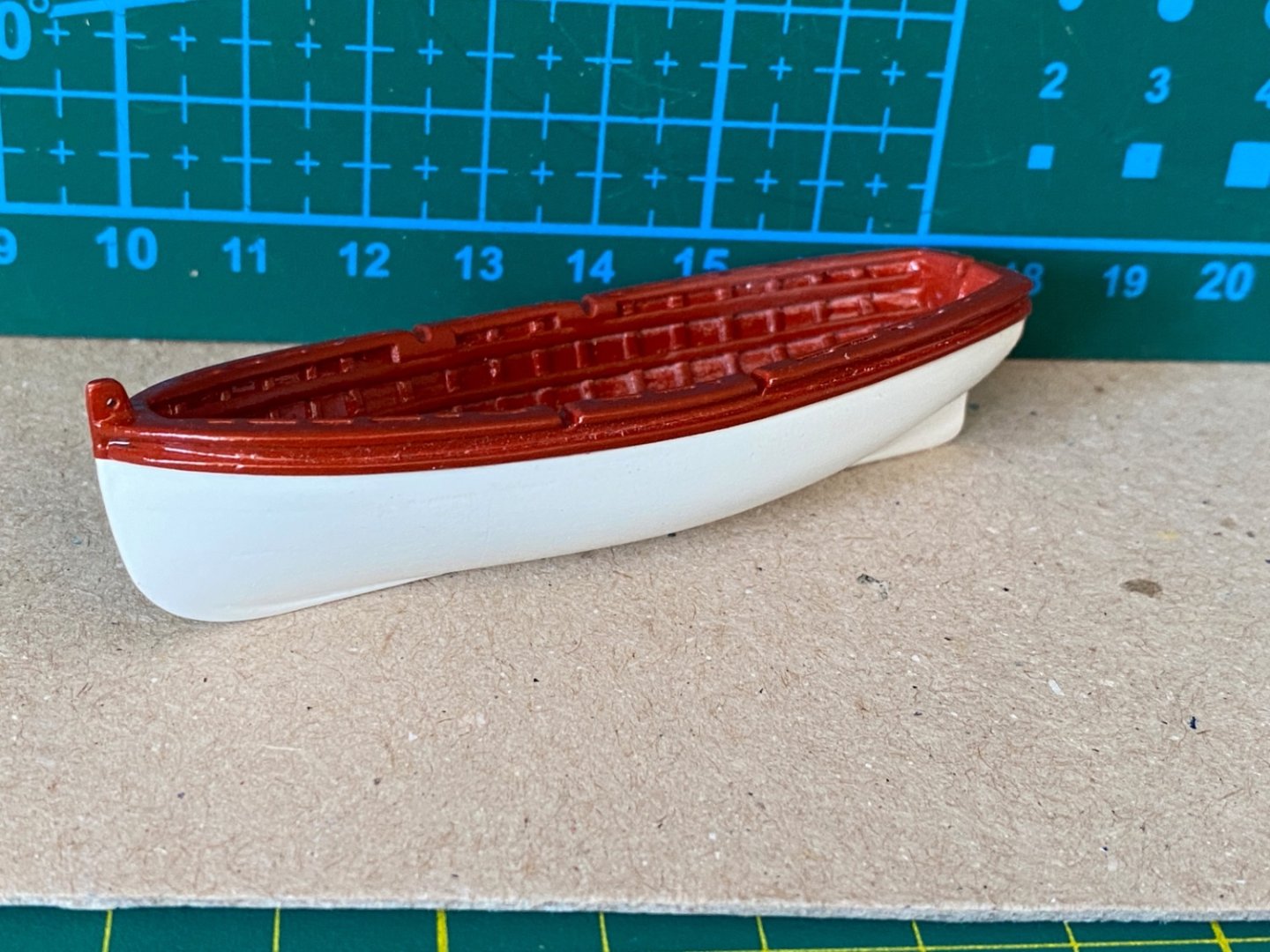
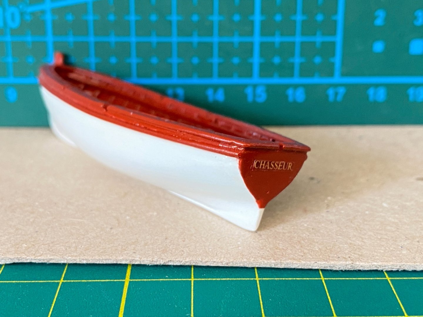
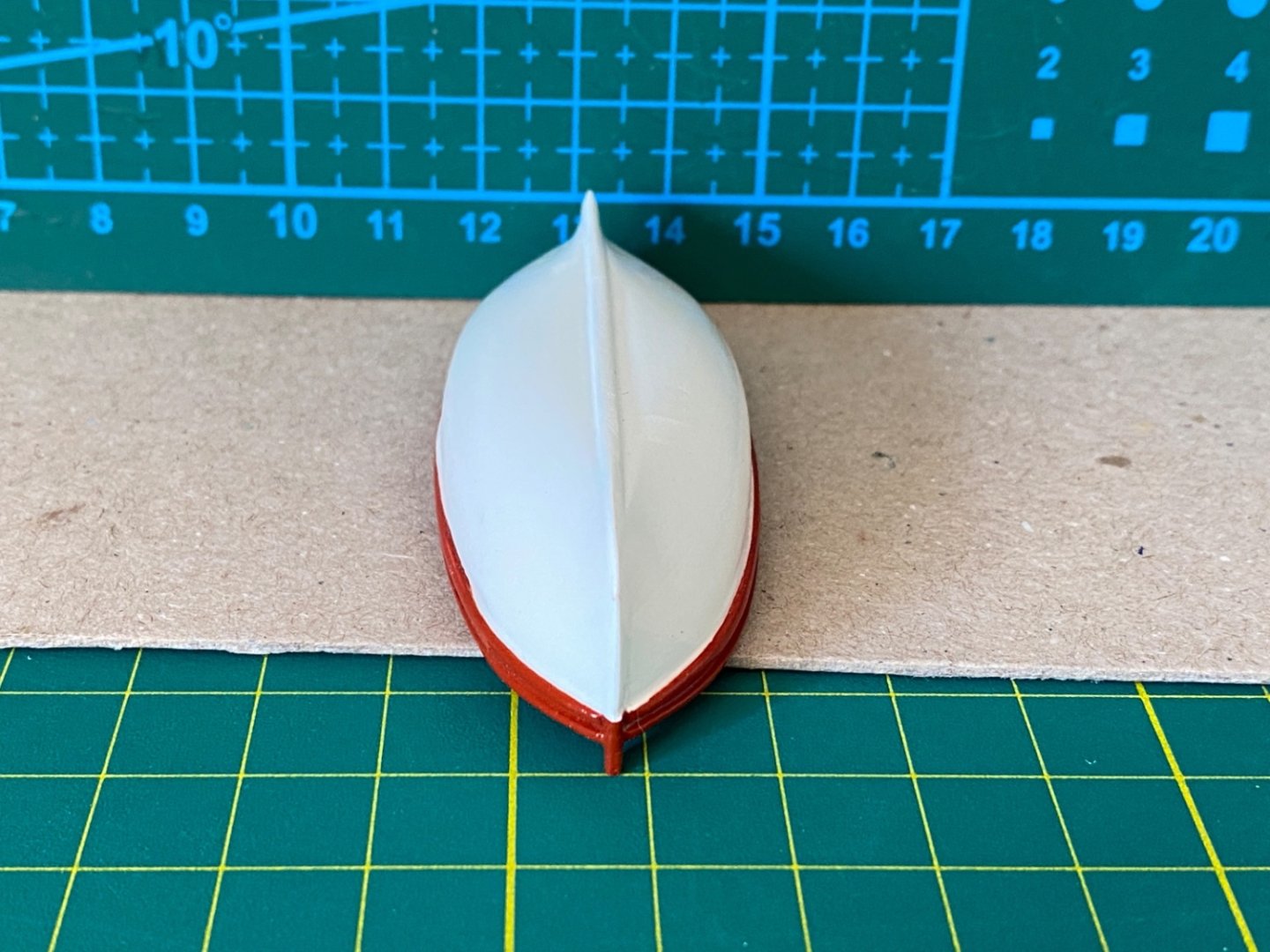
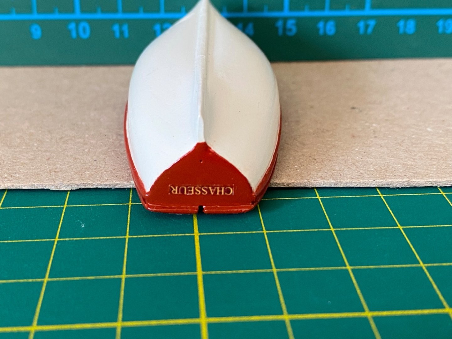
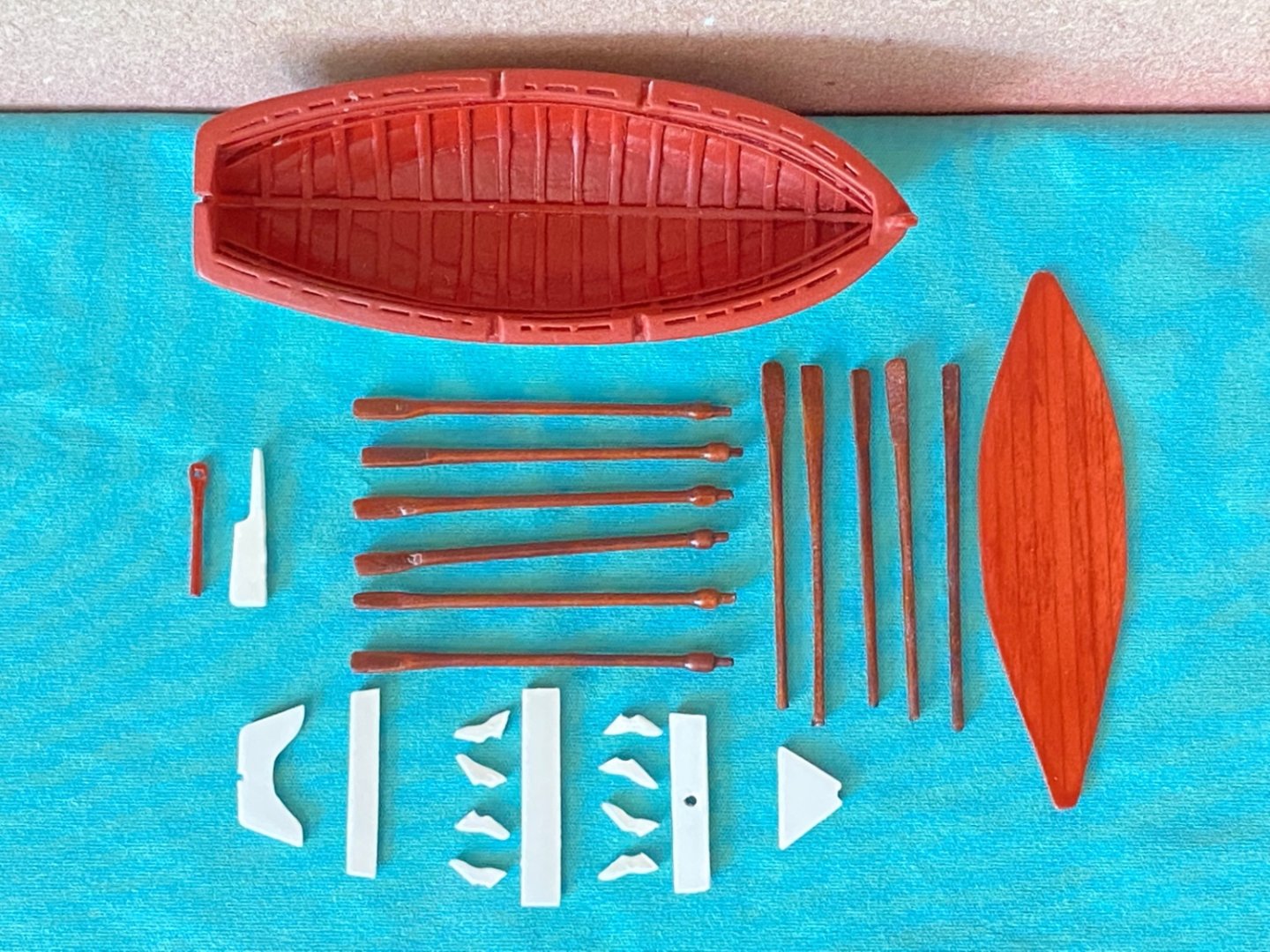
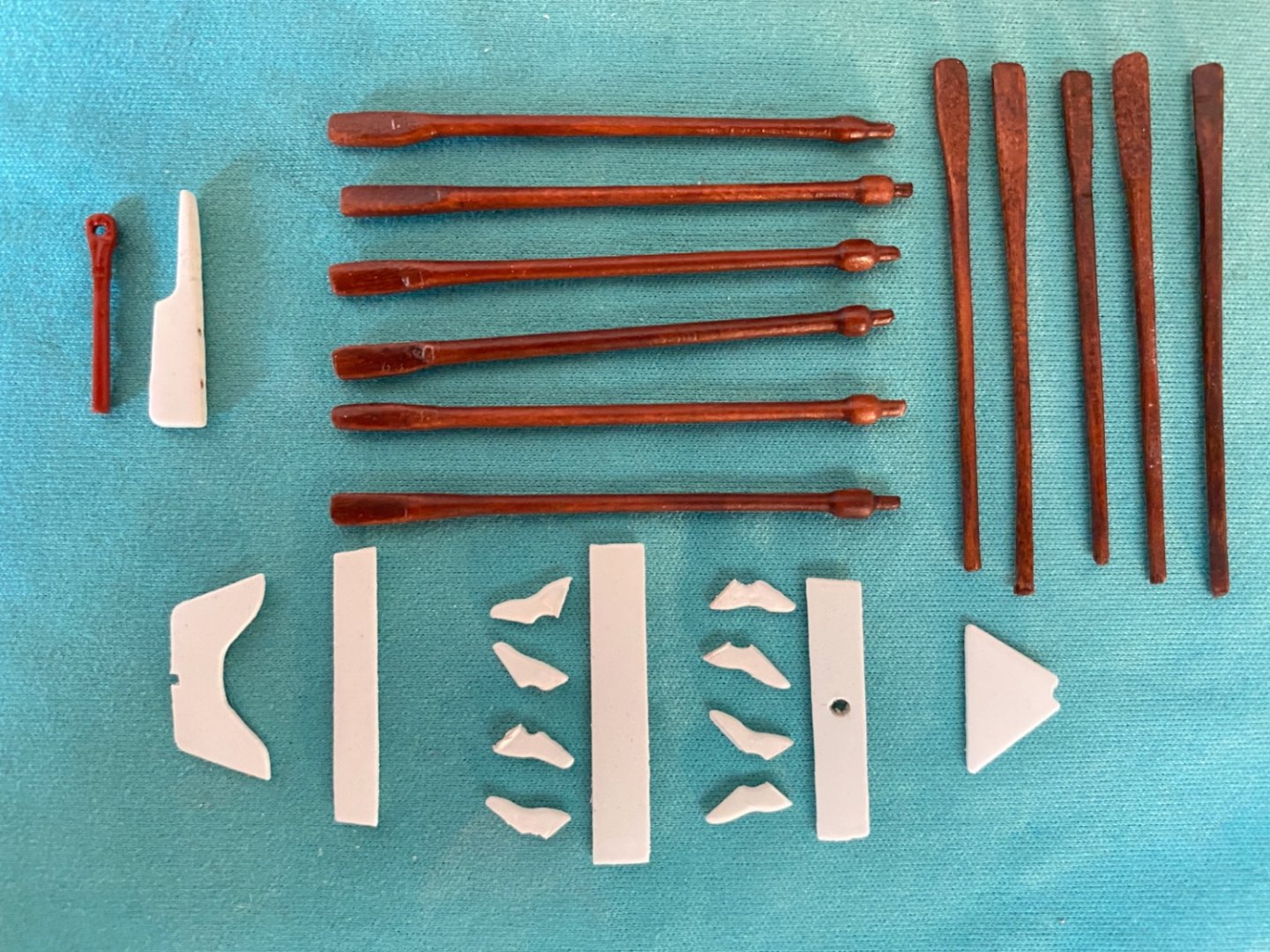
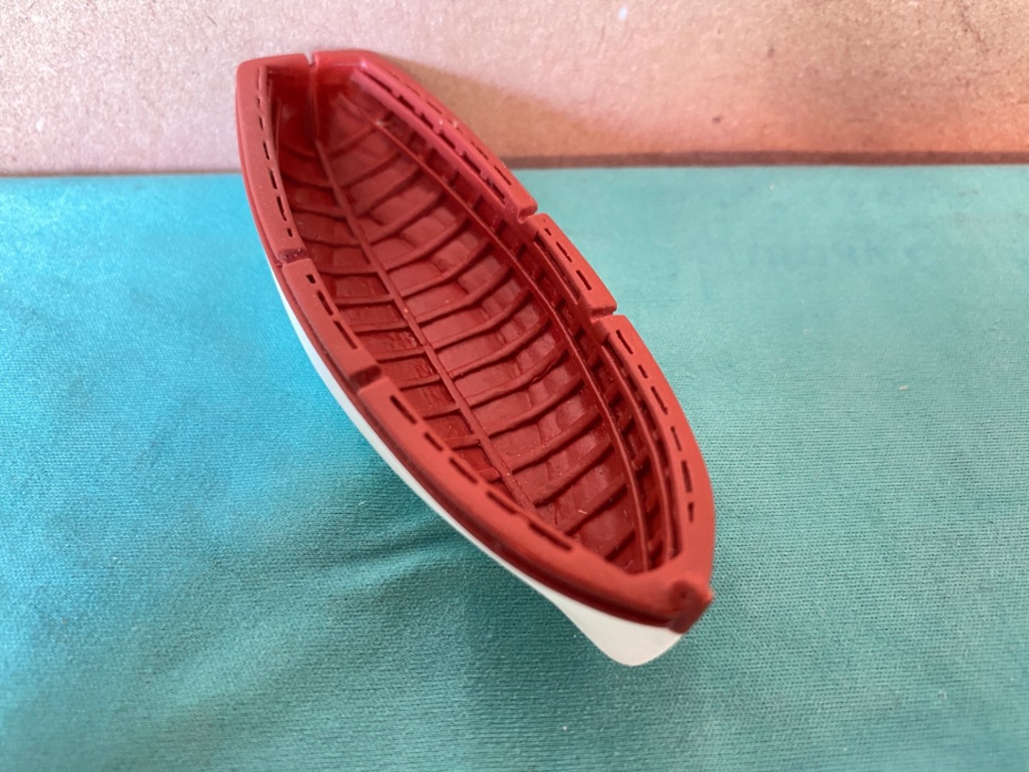
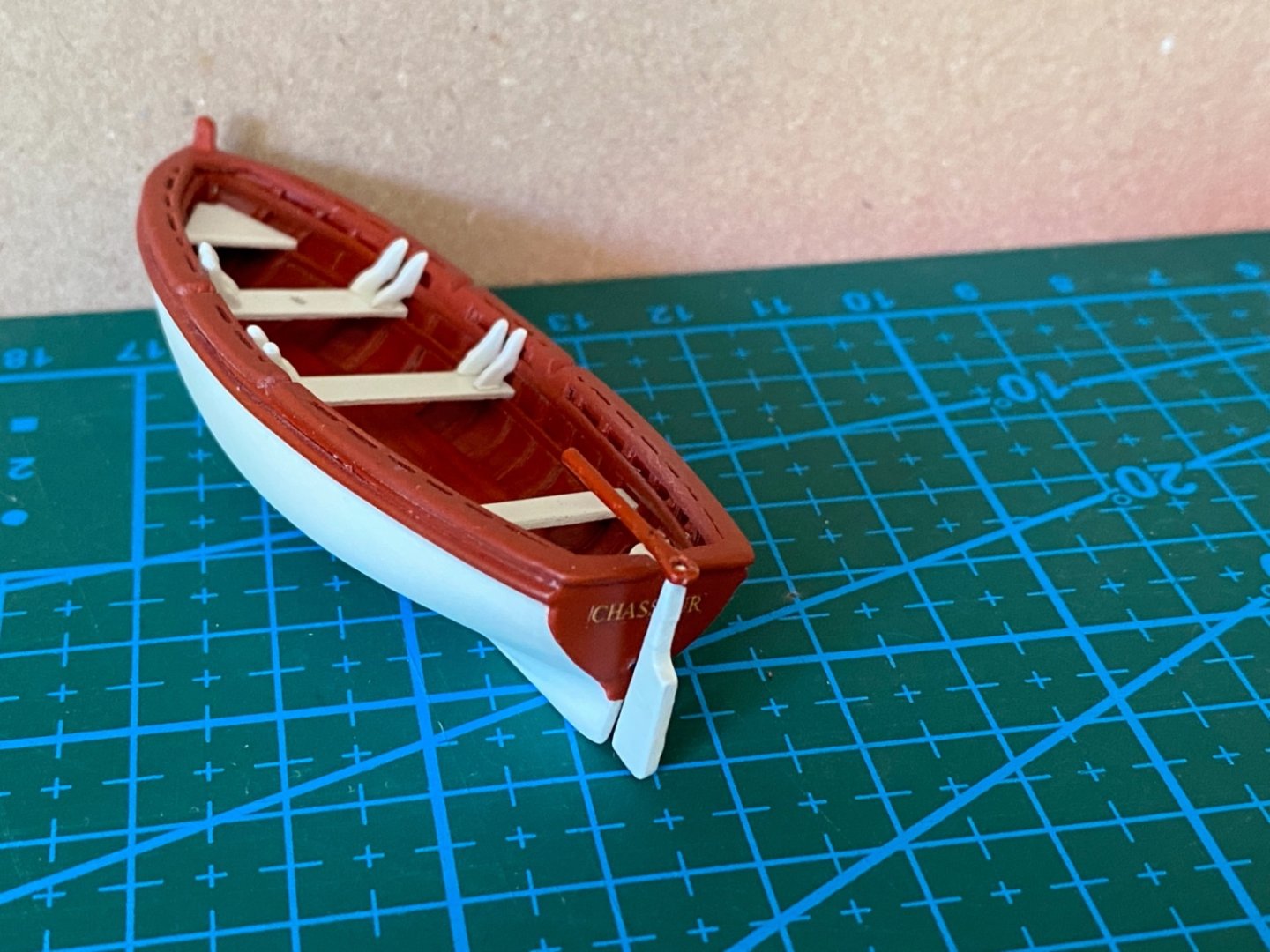
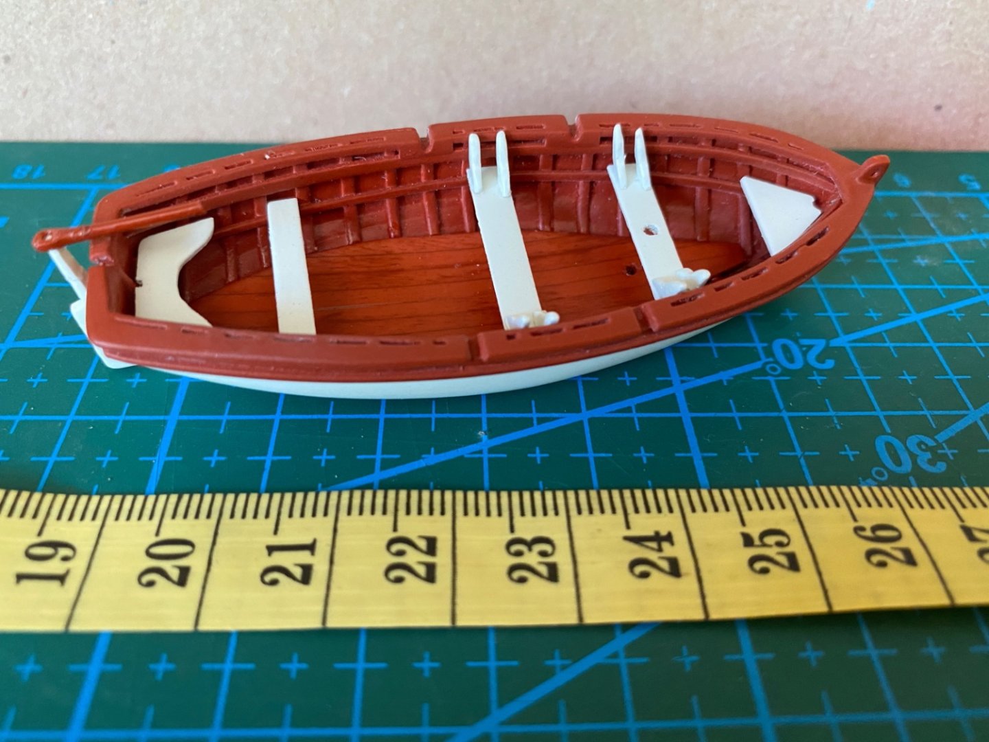
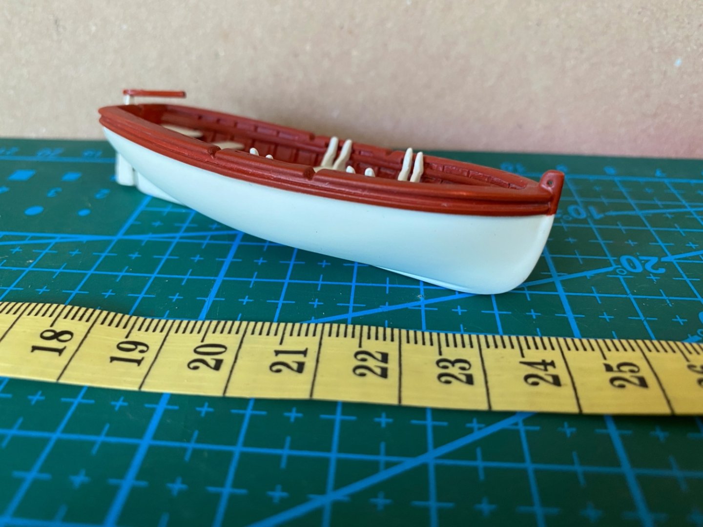
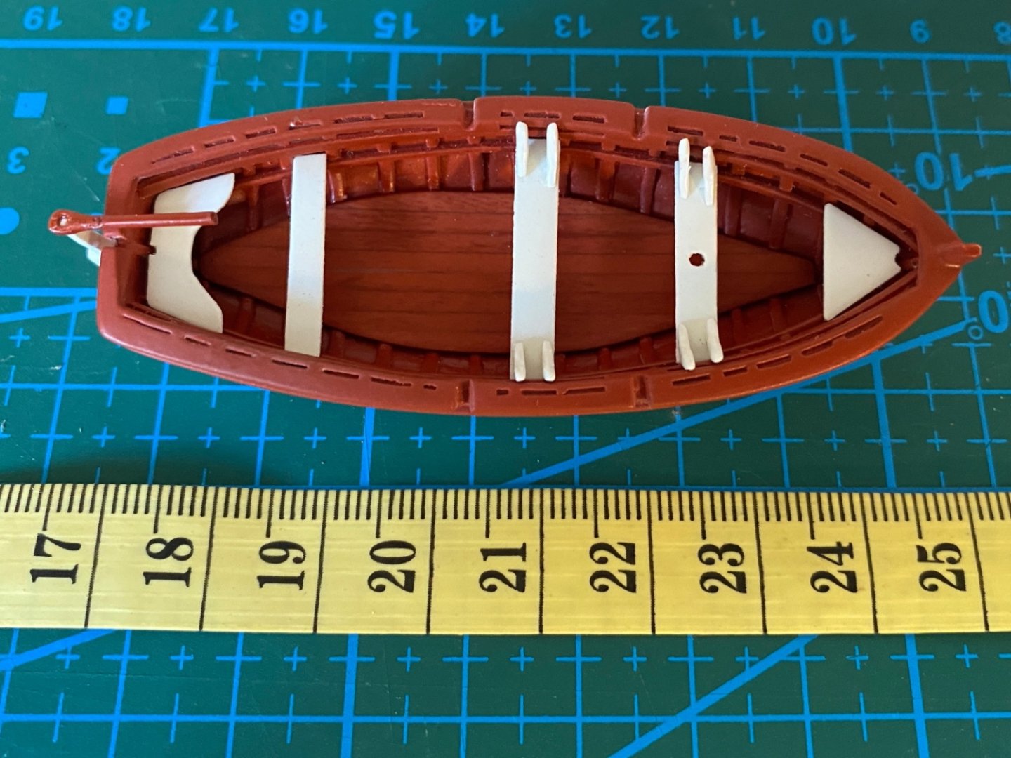
Pride of Baltimore II, harbored in Baltimore, has a beautiful boat named ' Chasseur '. ' Chasseur' is the name of a famous clipper in early 1800's which inspired Baltimore City Officials to build Pride of Baltimore in 1974 and finished in 1977. However the ship sadly sank in a storm in 1986. Pride of Baltimore II then was build in 1989. As you can easily see in the below photos, the boat has many beautiful details. Although many builders of this model decided to skip the details and cover the boat with some cloth hiding the inside of it, I decided to include as much detail as I can. The boat is build by 'Bread and Butter ' technique, the lifts are bread slices and the glue is the butter. Lifts, keel and rudder were carefully removed from their sheet. Each sheet has tabs at he ends. Wide tabs are stern and narrow tabs are bow. Kit's instructions dictate to start gluing from the the bottom part (#1) and go upwards to top part (#12). However as there was a lot of carving and sanding to be done, especially inboard, I decided to glue parts 1 and 2 separately from the parts 3-12. The plan was to glue the created two parts after their maximal sanding and/or carving. I used Dremel Stylo handpiece with several sized diamond burrs for carving and suitable sanding material. I started with the job with the bottom 1+2 piece. Although a nice curvature was formed in this stage, there will be more job needed when this piece was glued to the upper block. I continued with the inboard surface of the upper block. I glued the bottom and upper blocks. I cut the bow and stern tabs to shape and glued the keel after dry fitting trials. Outboard surface sanding was done. Fine sanding of inboard and outboard was finished. Details added are shown with red arrows in the following photos. A three piece ( small stern and bow pieces) false keel (red arrows) was installed on the inboard midline. A photo of the boat at this stage I decided to add curved wood strips to resemble frames to inboard. These frames are paralel to each other and perpendicular to the false keel.Frames are cut to size and bended with an electrical plank bender. The frames were installed in groups starting from the middle and finally reaching stern and bow. During the installation process the boat was fixed to base with masking bands. Then I started to fill the gaps on the outboard surface. I filled the gaps with saw/sanding dust and applied liquid CA just like the model's hull. More details were installed inboards (Red arrows) Oars were prepared by turning wood in Dremel 4000 mounted on Dremel Workstation. A few trials were made. Thwarts and knees were prepared. Rudder and tiller too. The boat and all the other parts were ready for the paint job. Bottom battens were mahogany stained. Oars were painted by Modelexpo Maple. Tamiya white primer was used. This was followed by Tamiya matt white. The rest of the boat , including the stern, was stained by Mahogany stain. ' Chasseur ' lettering was a decal and placed on the stern. Tamiya gloss coat was airbrushed on the outboard surface. Finally matt clear was airbrushed to all parts of the boat. The rudder , although seen as white, was mahogany stained later. Boat after gloss coat. Boat and all the parts after matt coats. Although the 'Chasseur' lettering seems to be fine if viewed from a distance, a couple of more clear matt coat would have been better if apllied. Then all the parts were glued to the boat. Unfortunately I do not have pictures relating to the preparation of the boat's stowage cradles. They were prepared from thin scrap wood. They were dry fitted with the boat during the shaping of their inclined edges. Those edges were covered with thin gasket material , from various Modelexpo Horse Drawn Vehicle kits.


- 114 replies
-
- 3
-
-
-
- Pride of Baltimore II
- Model Shipways
- (and 1 more)
-
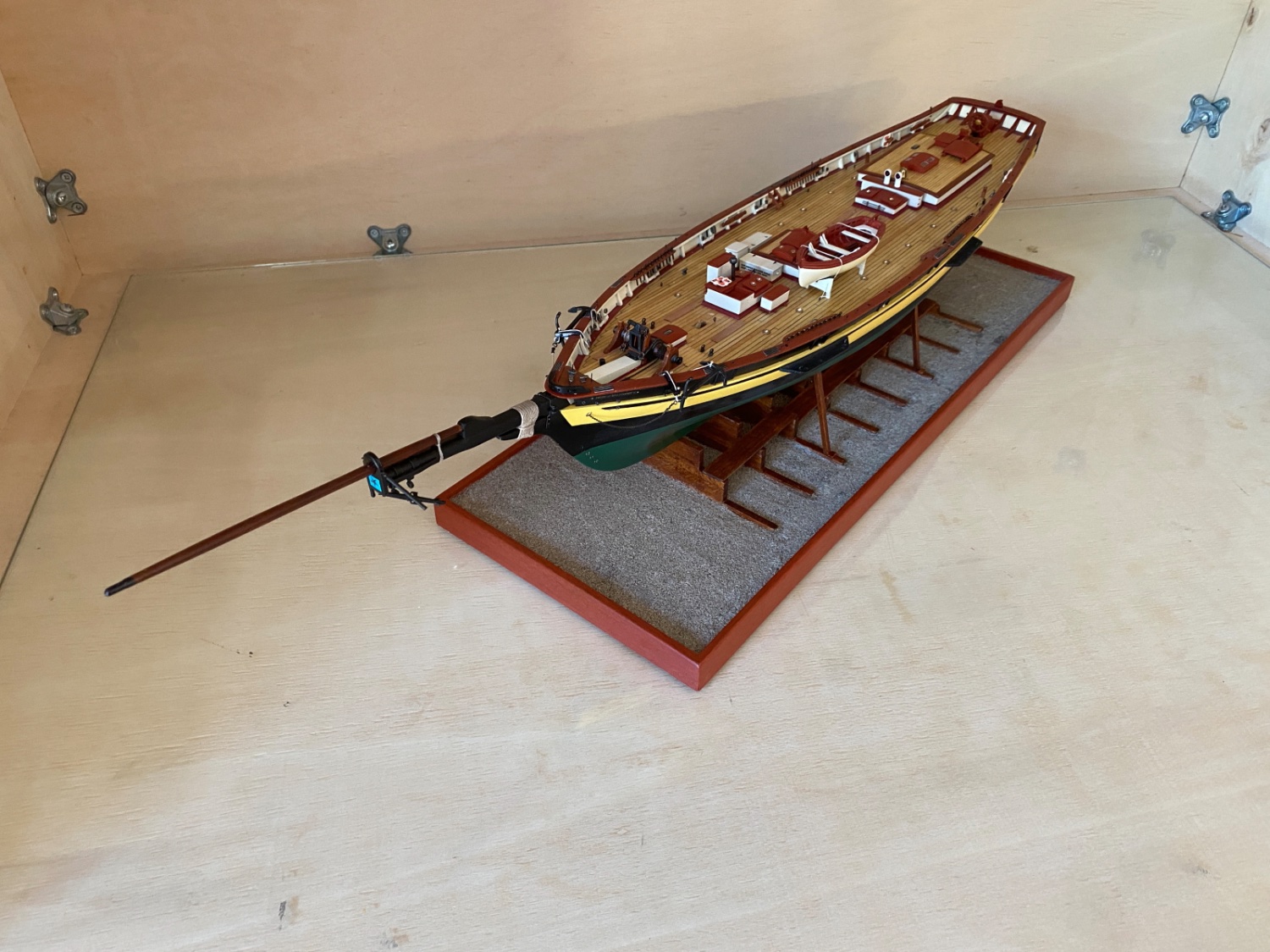
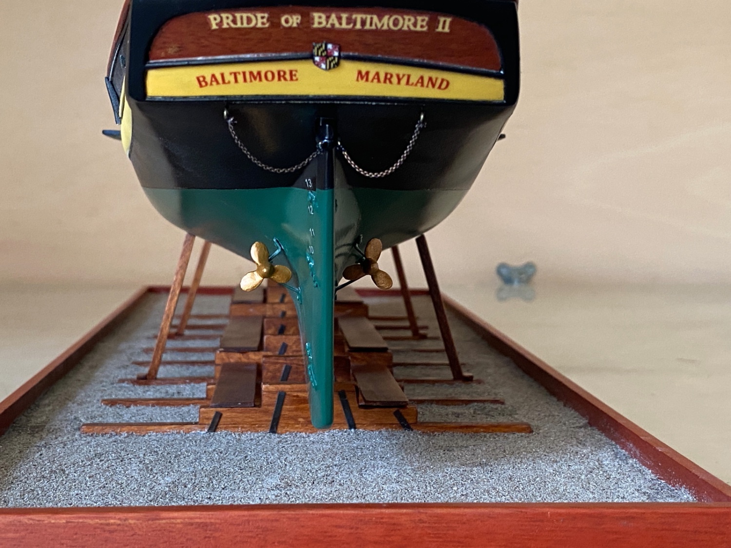
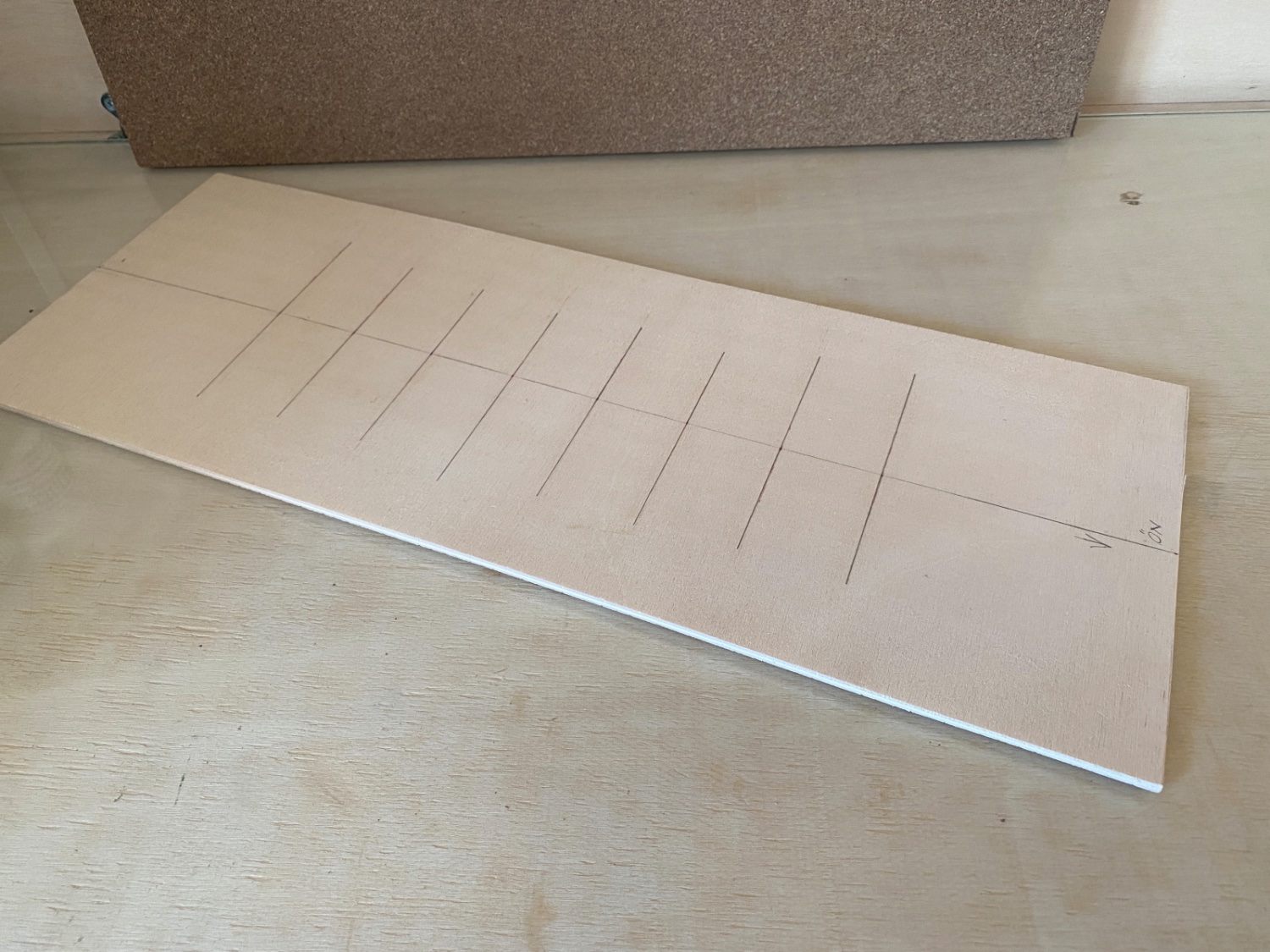
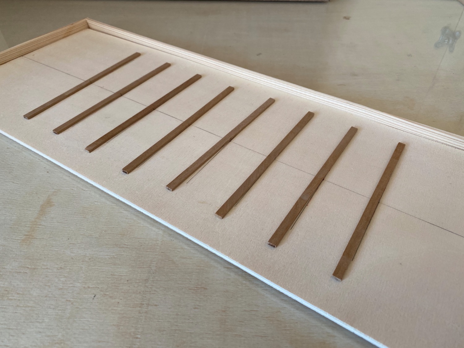
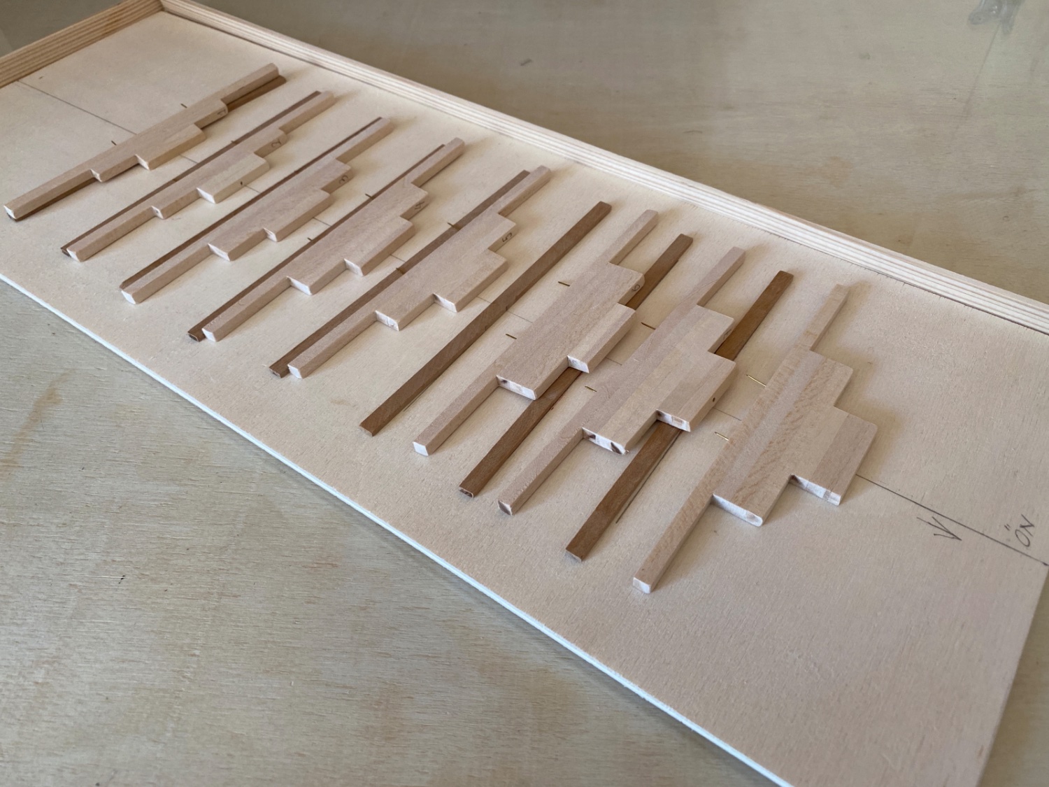
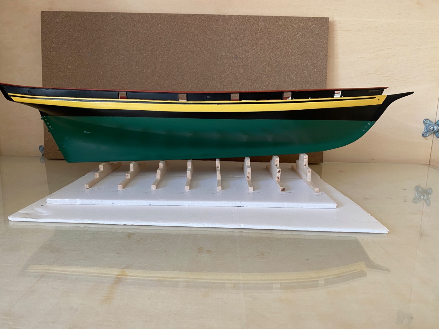
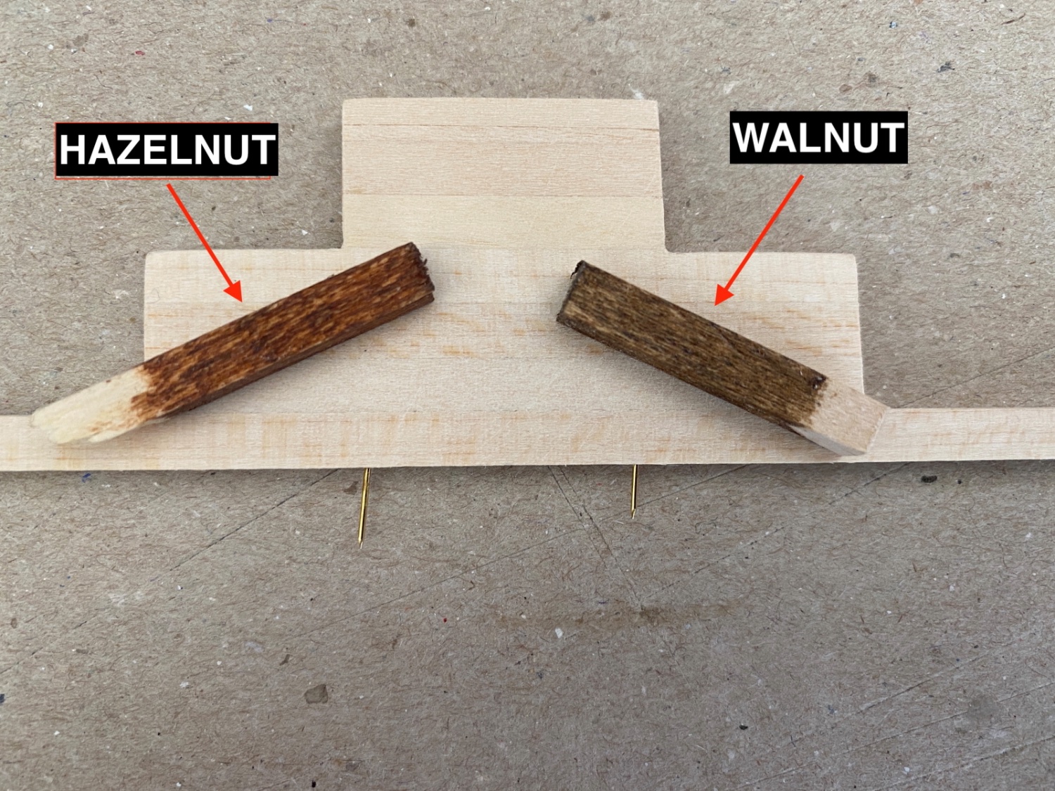
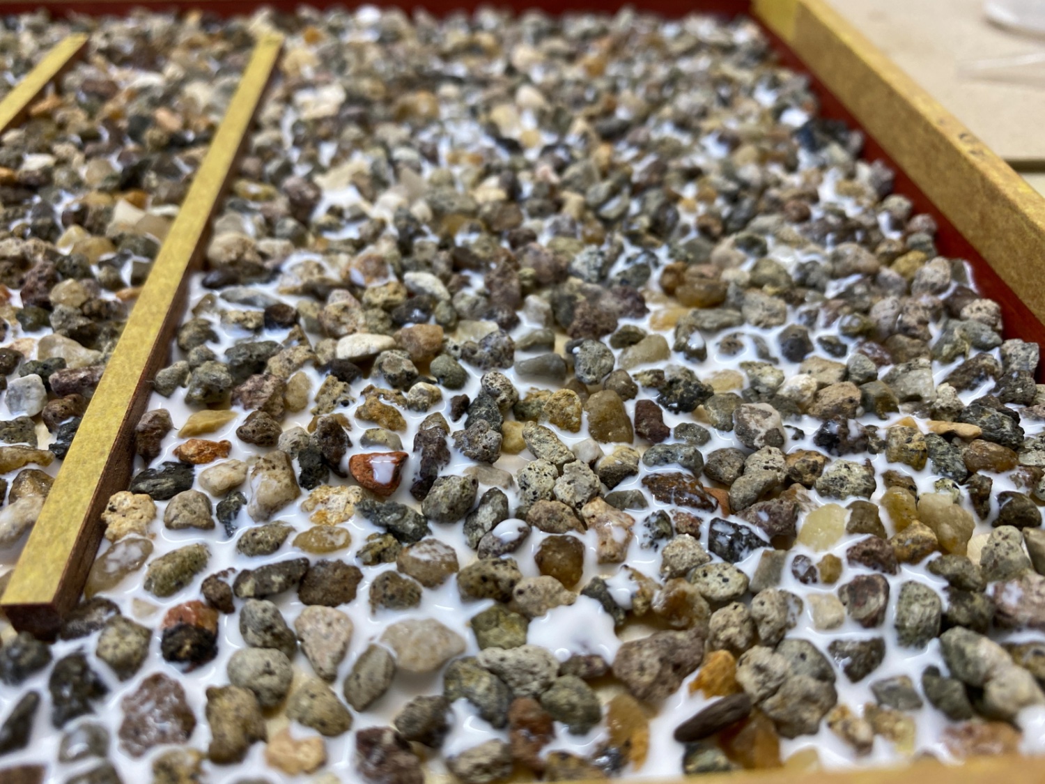
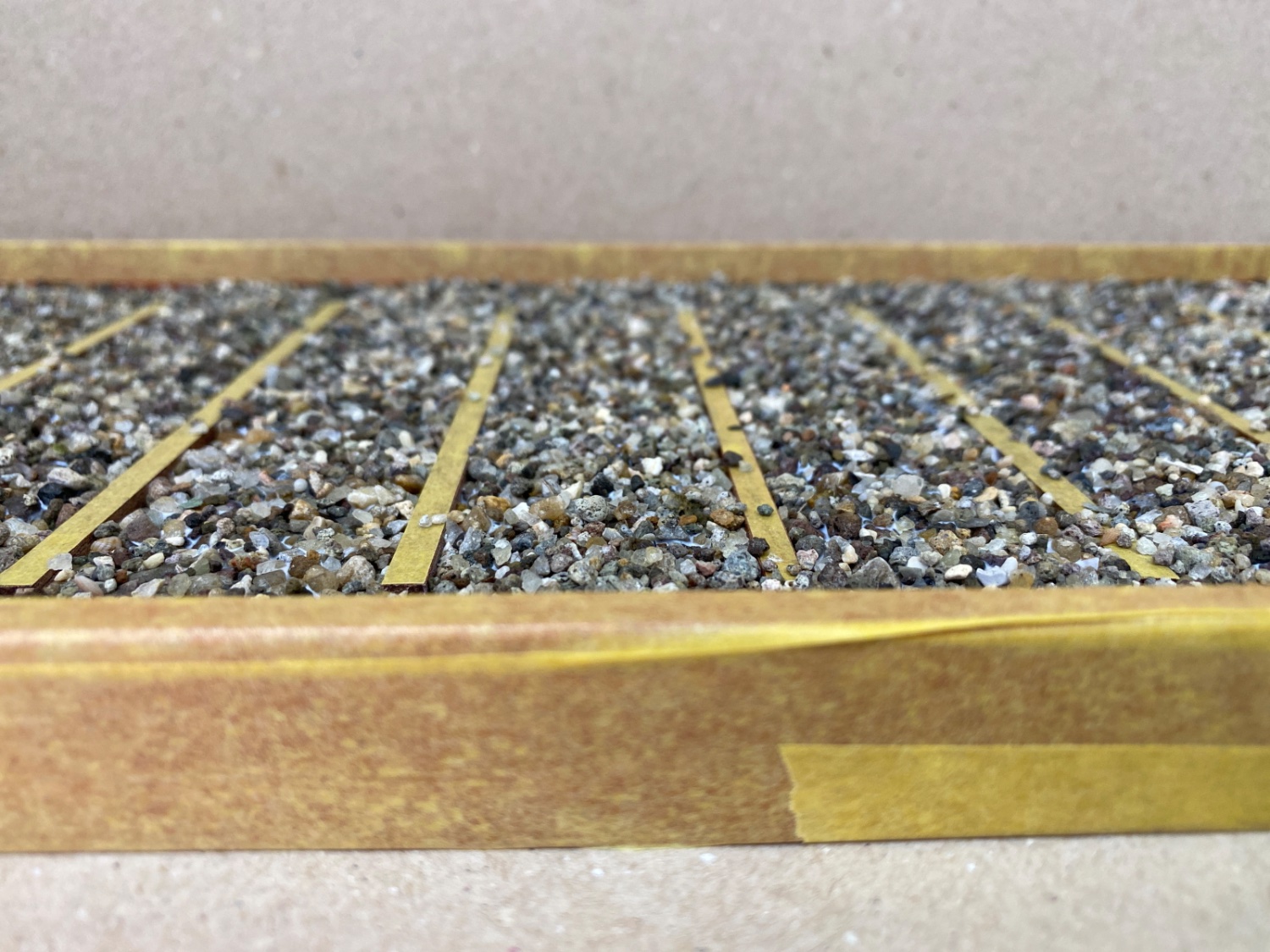
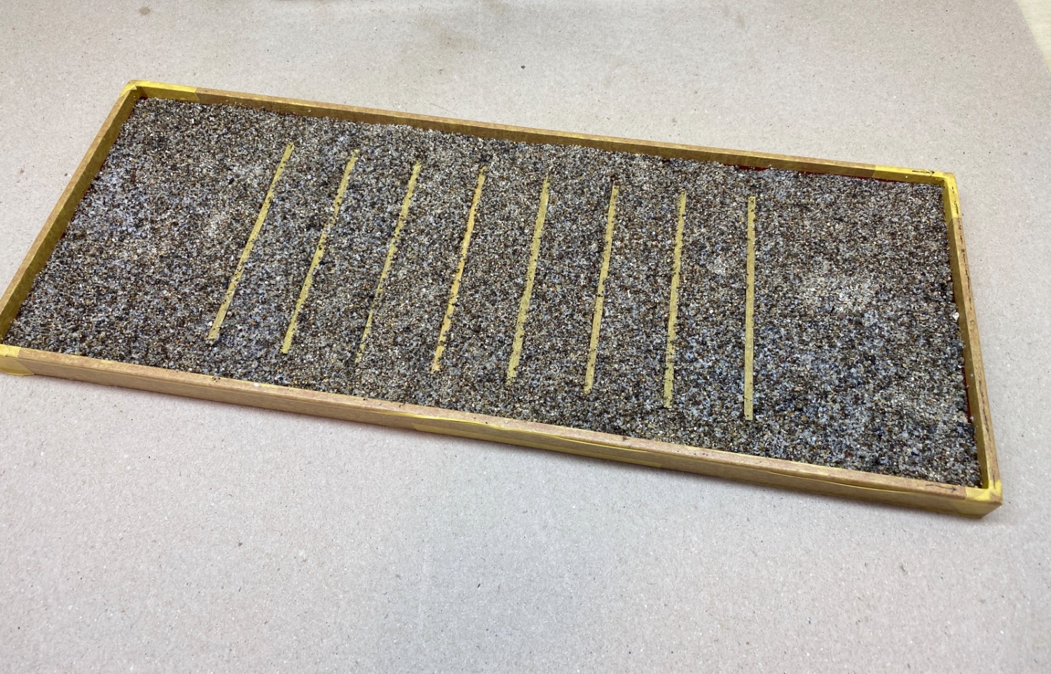
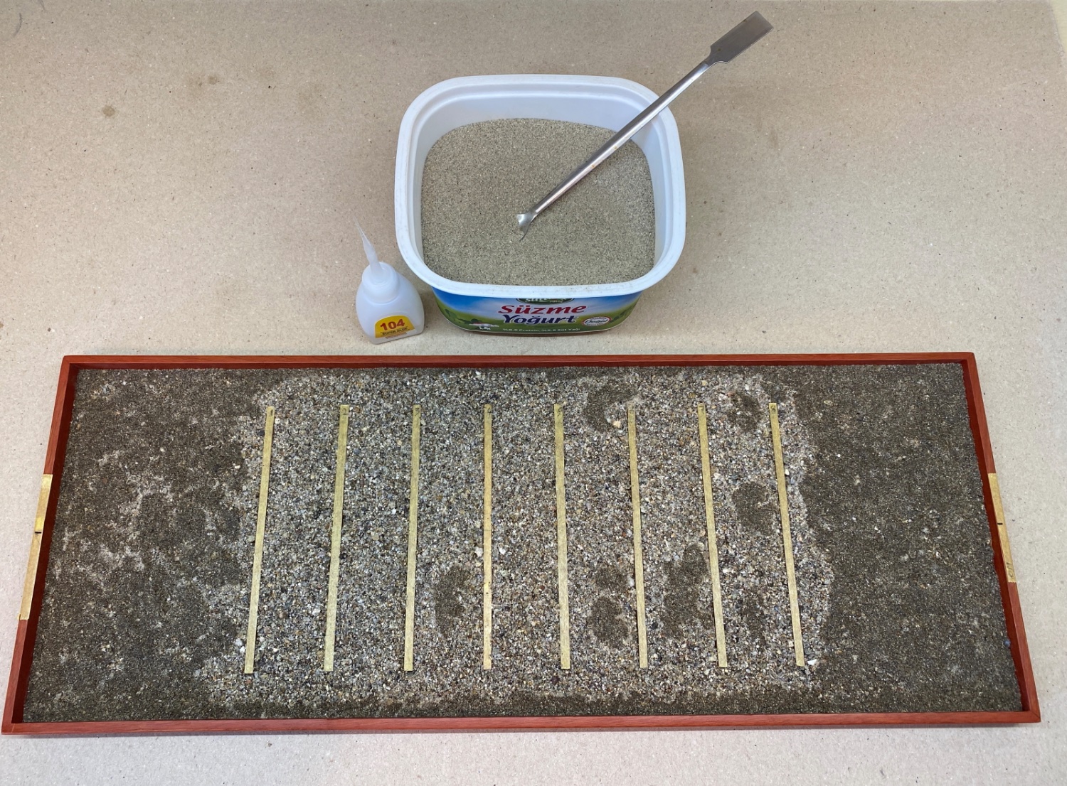
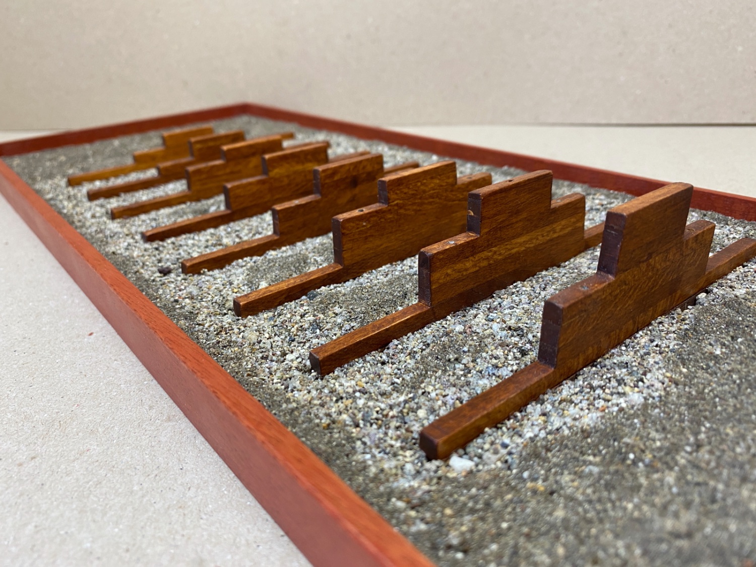
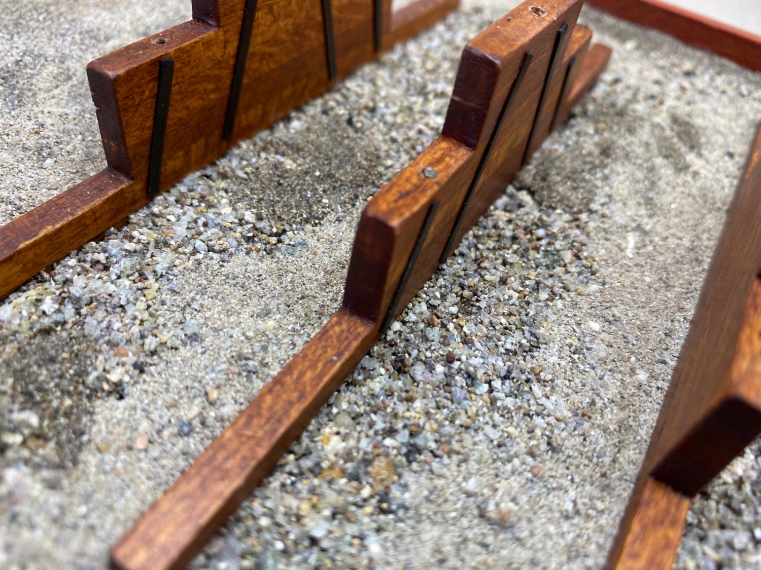
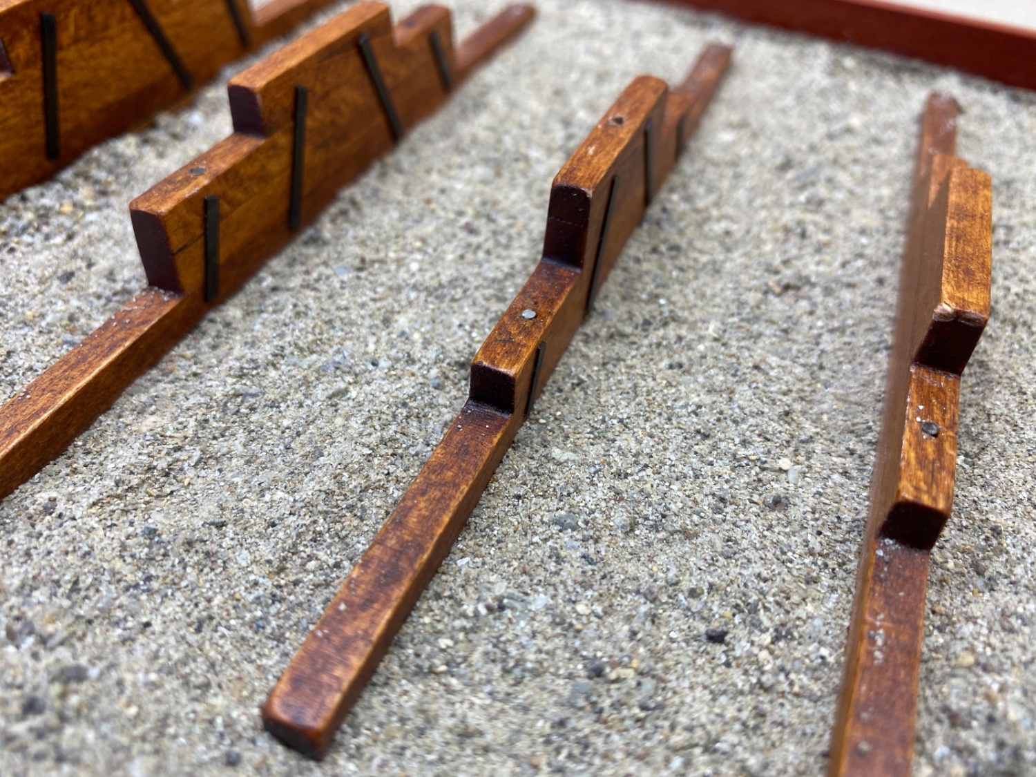
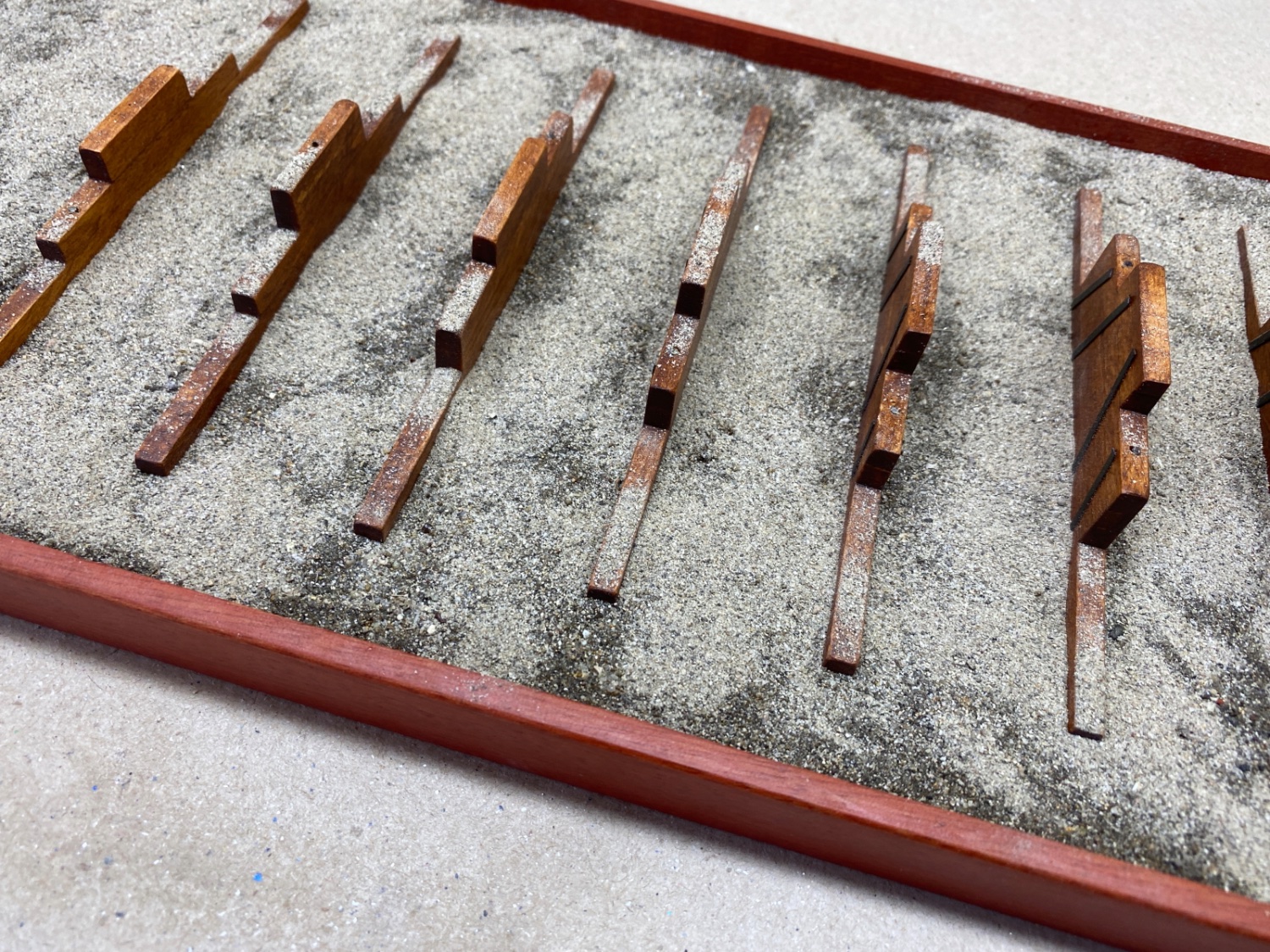
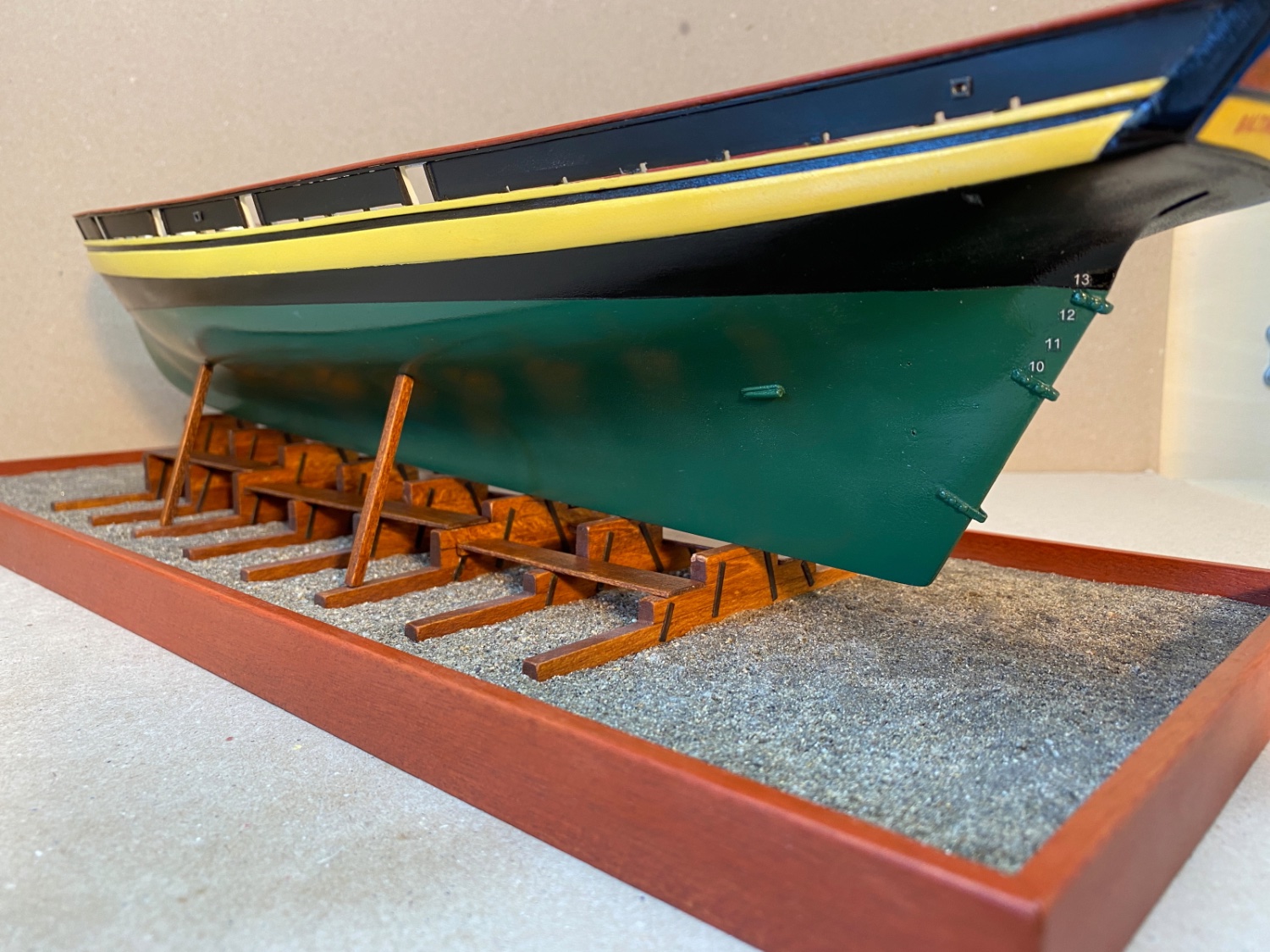
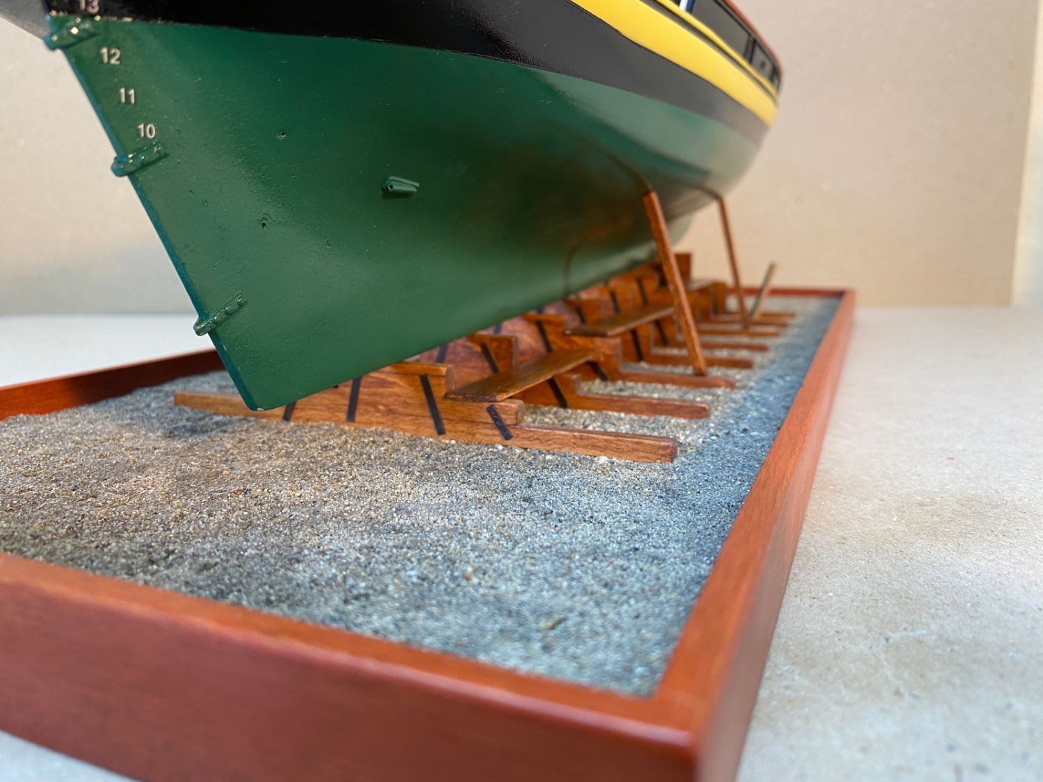
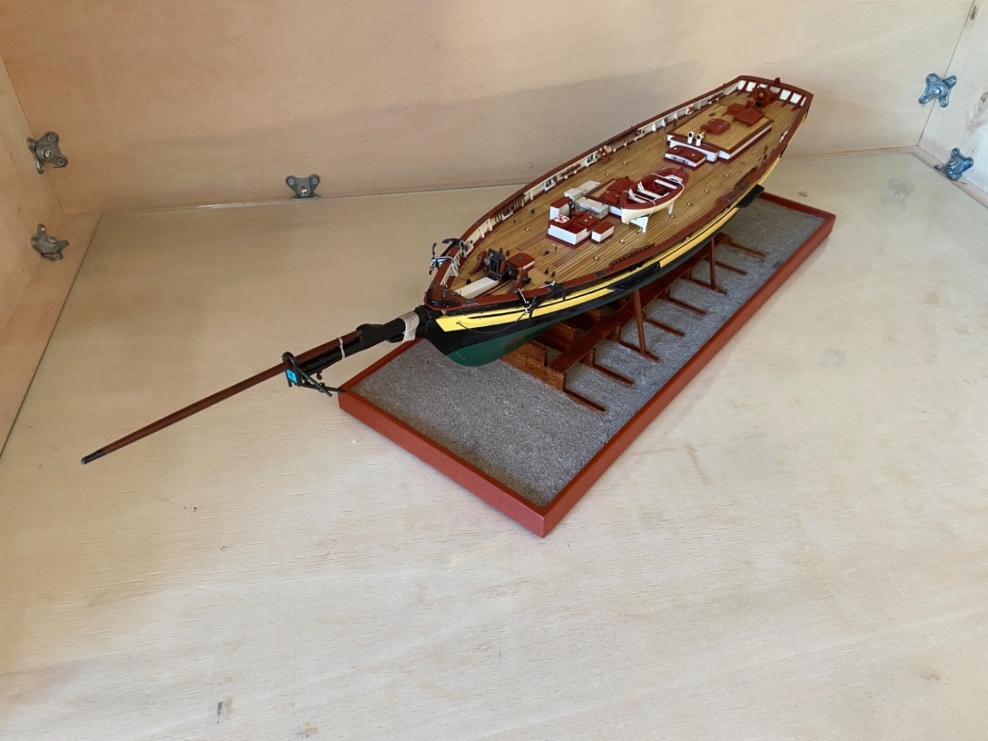
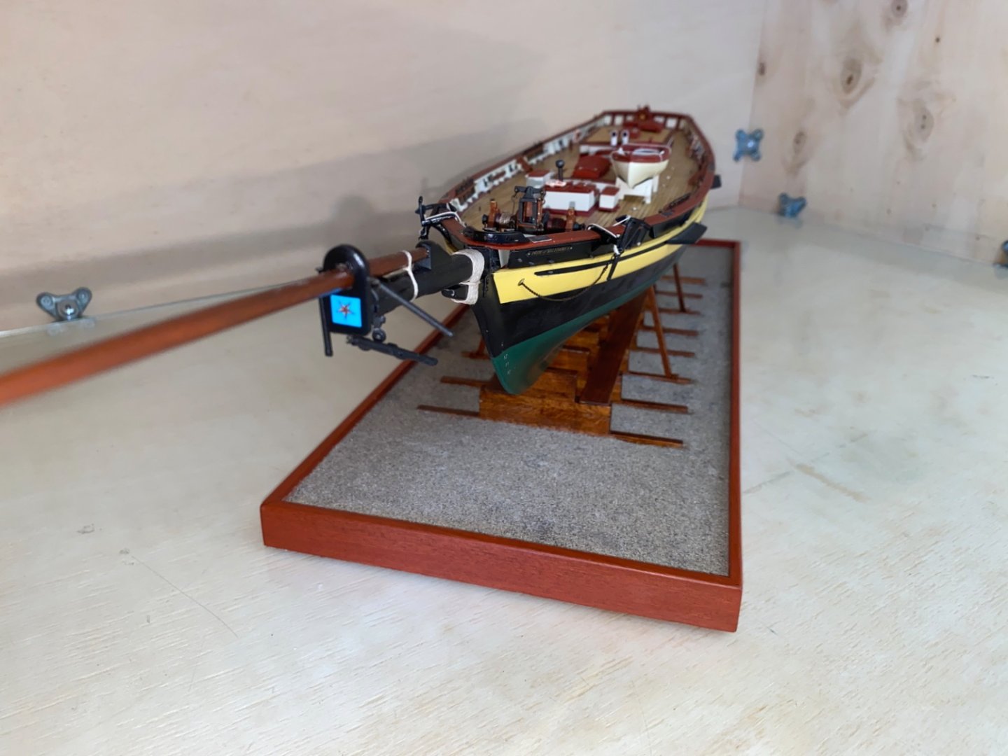
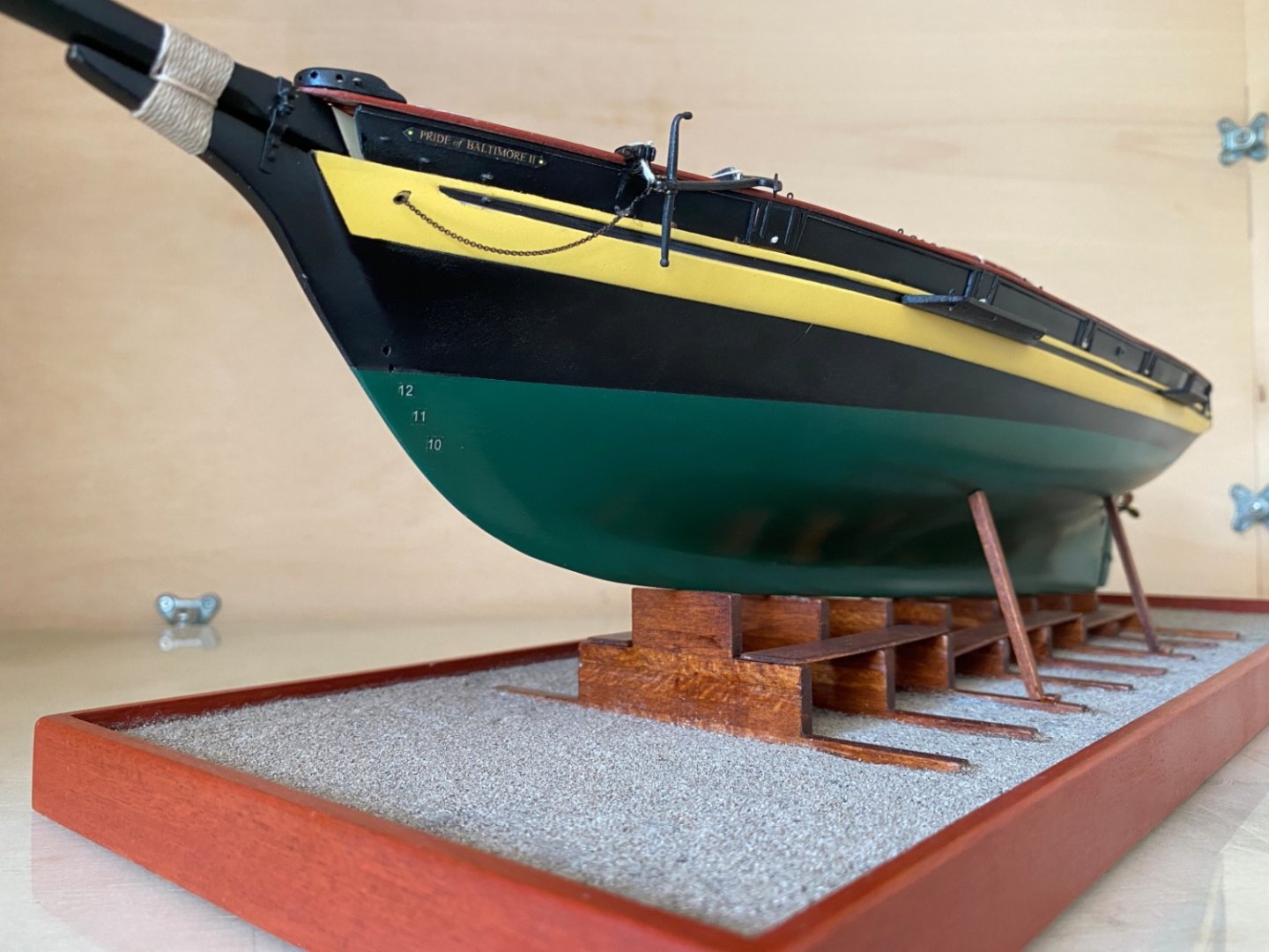
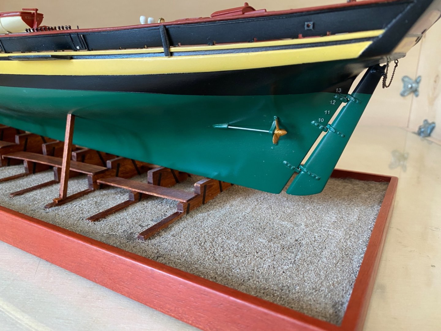
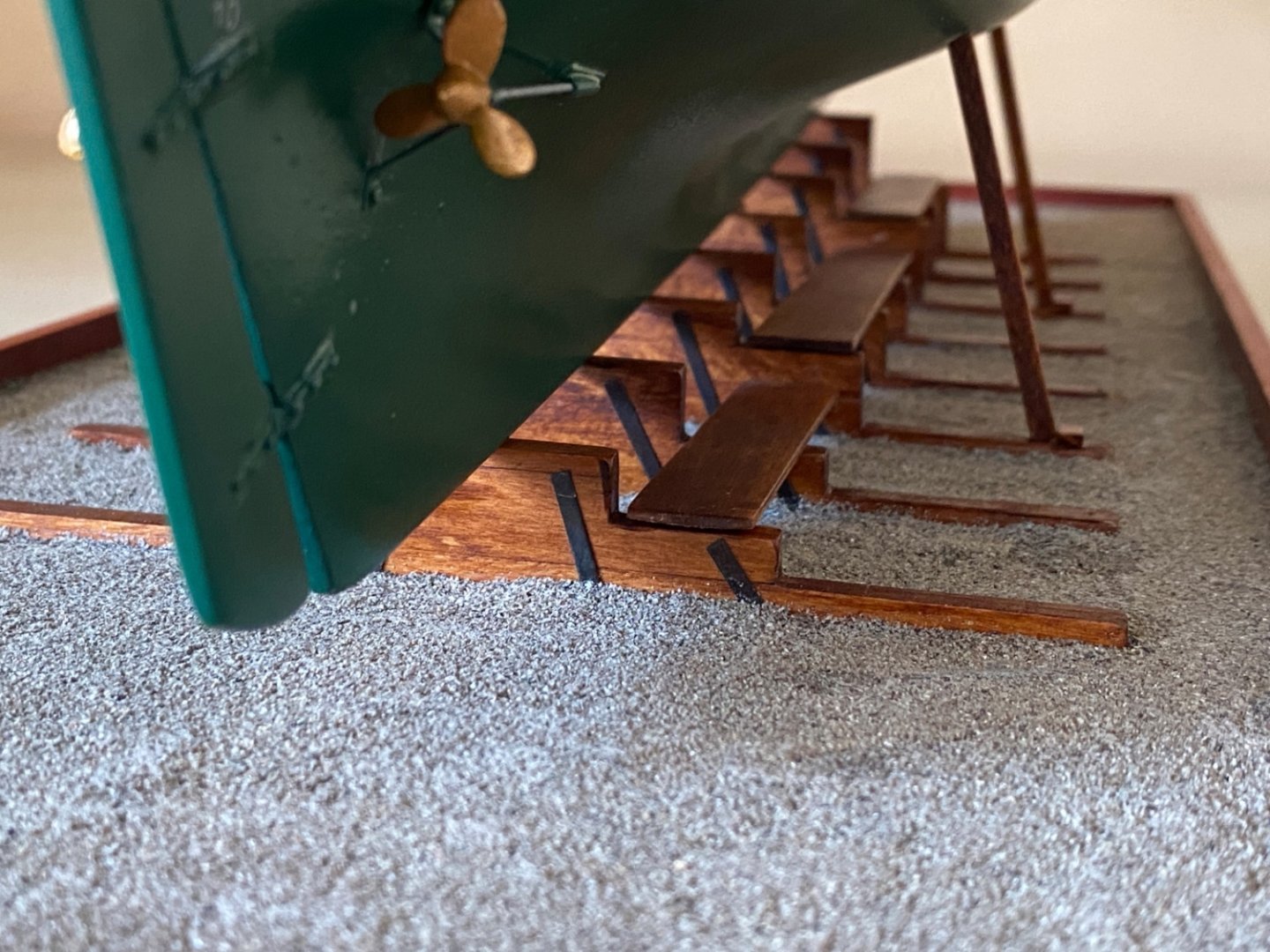
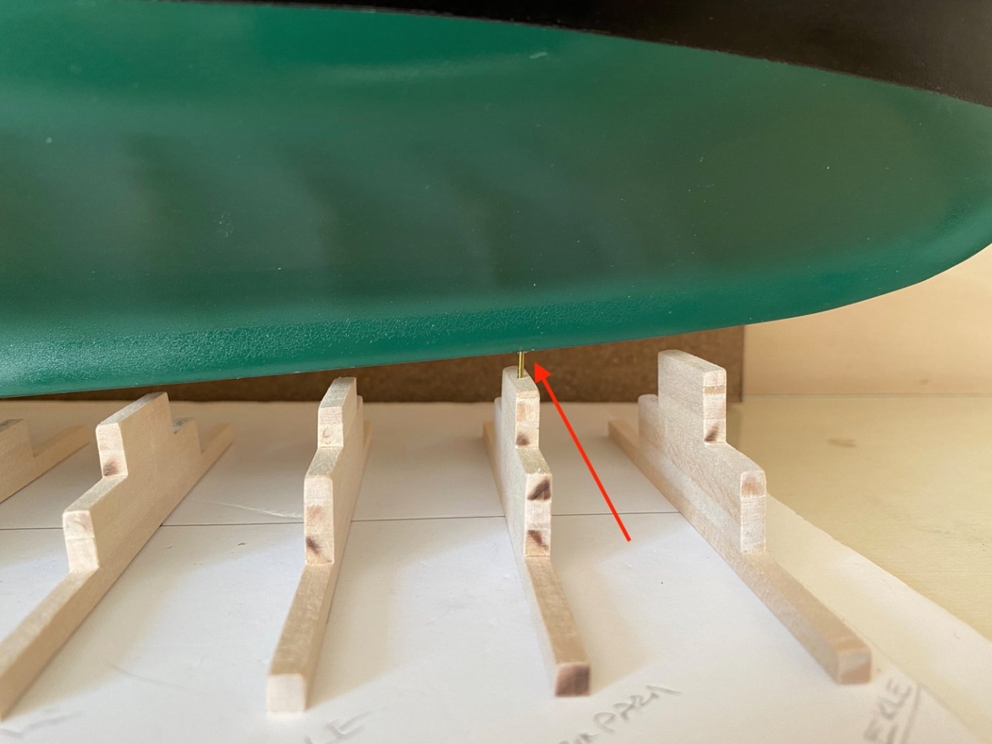
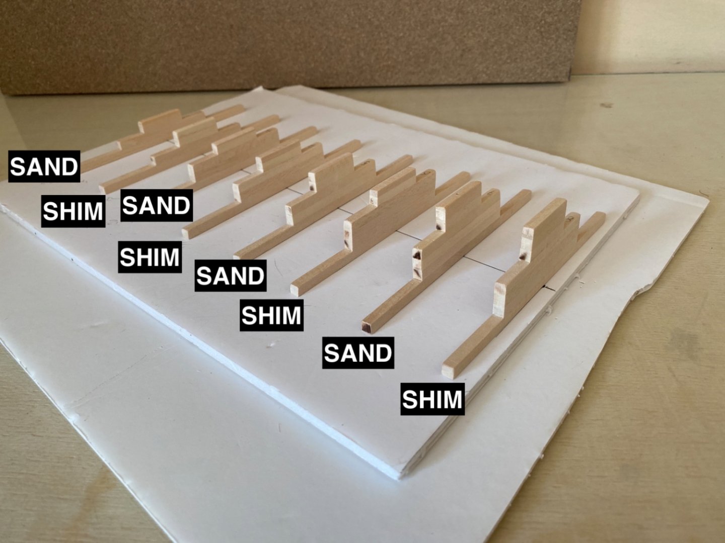
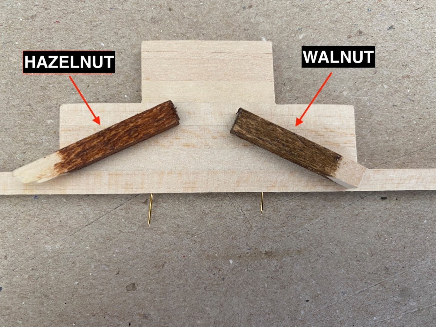
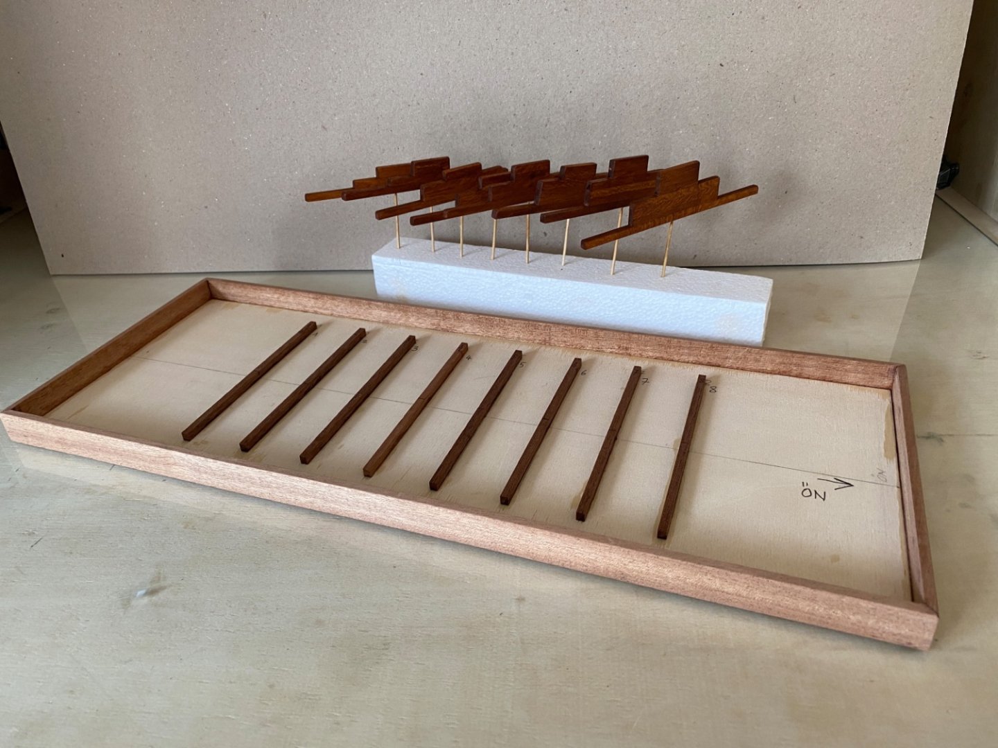
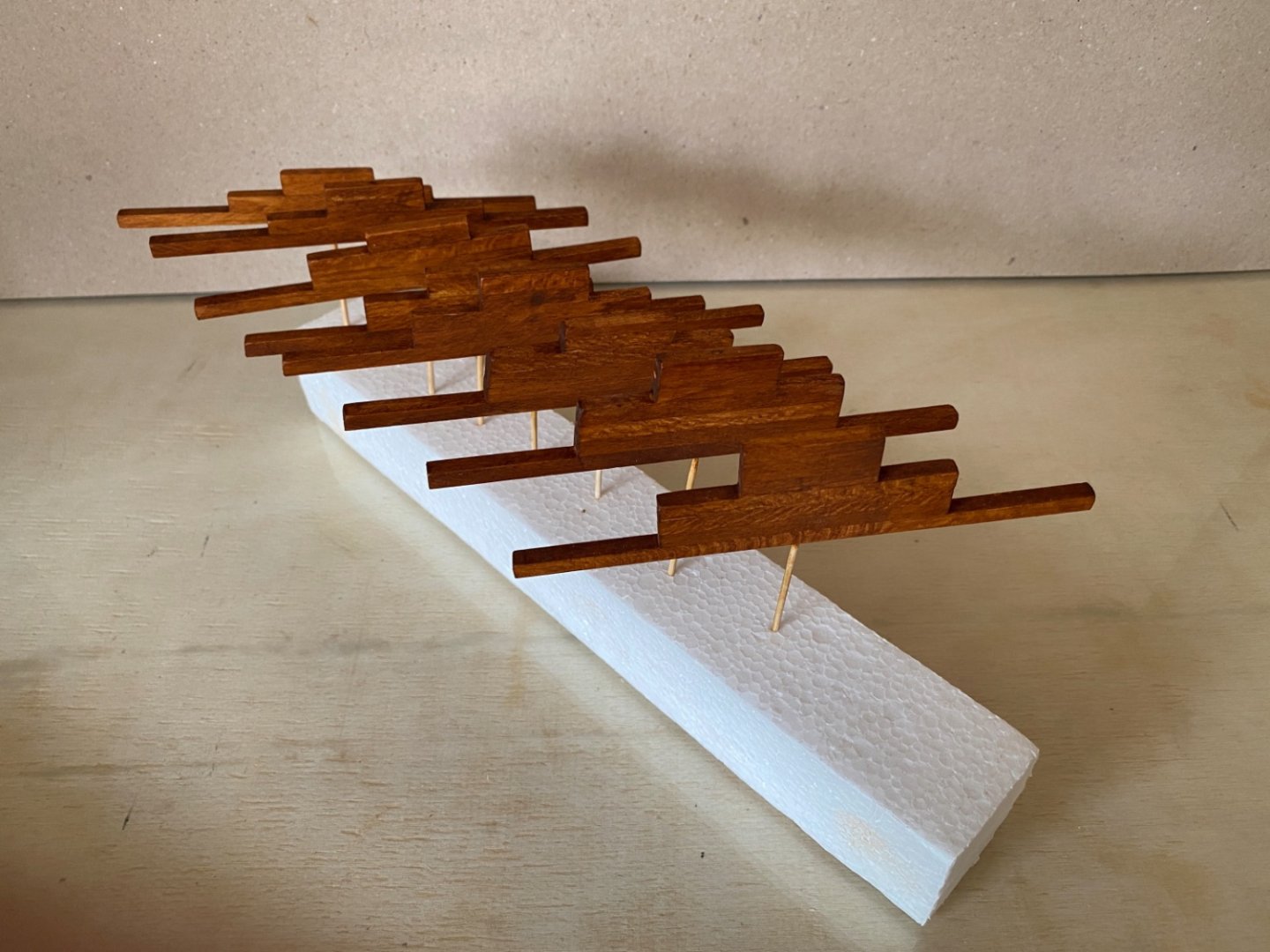
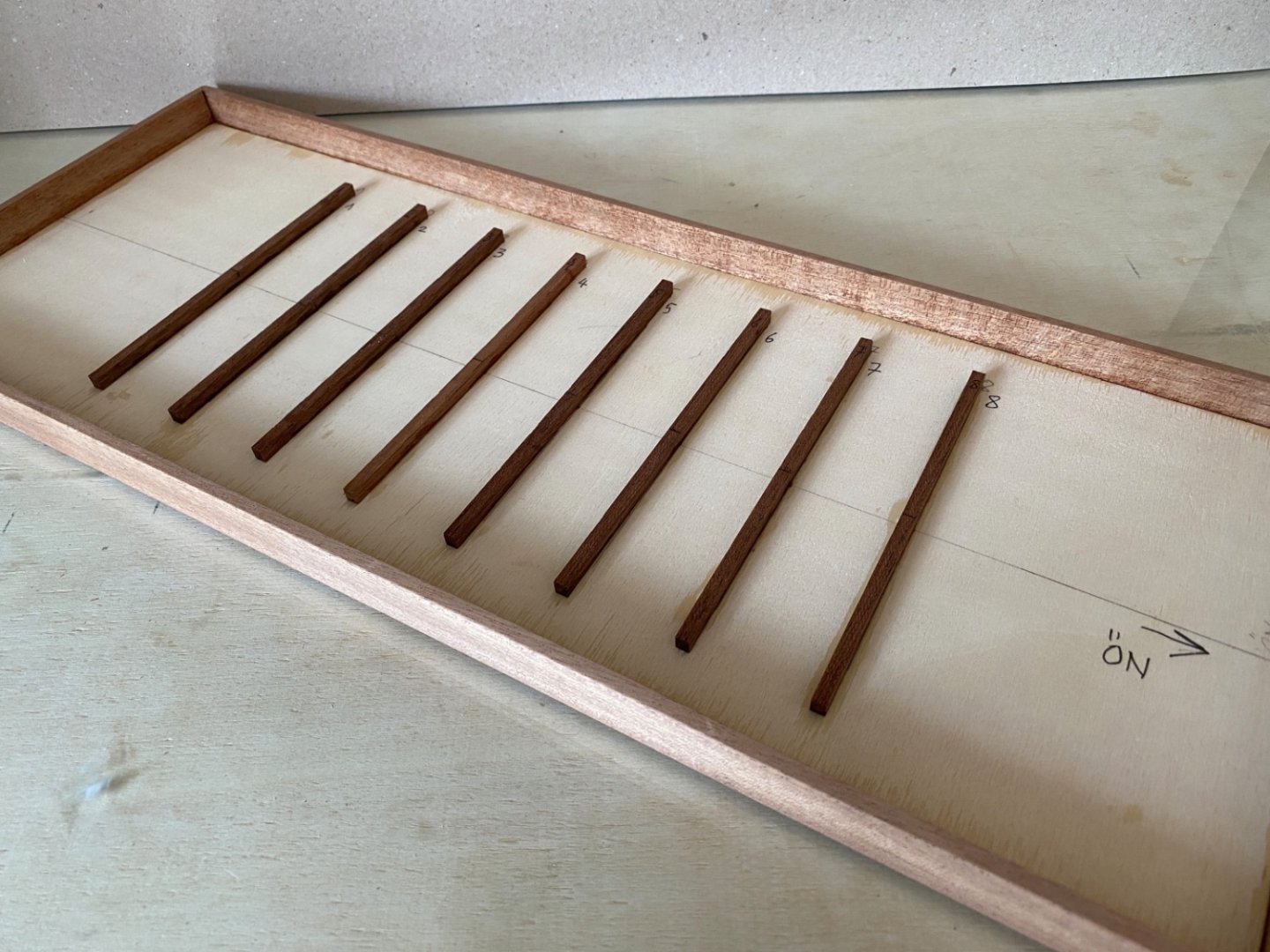
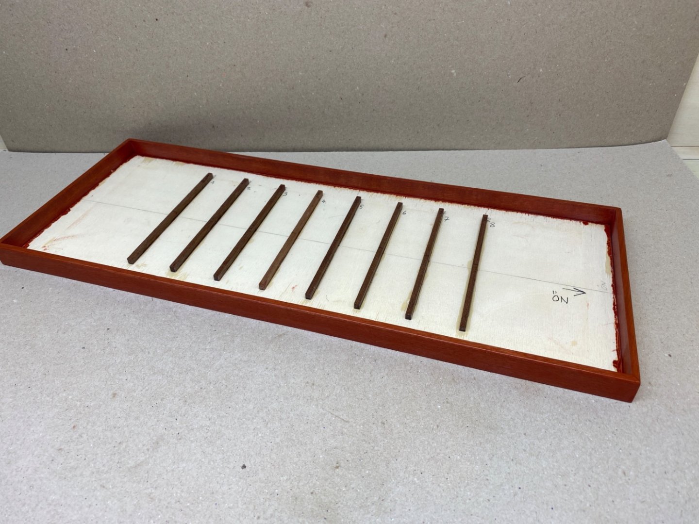
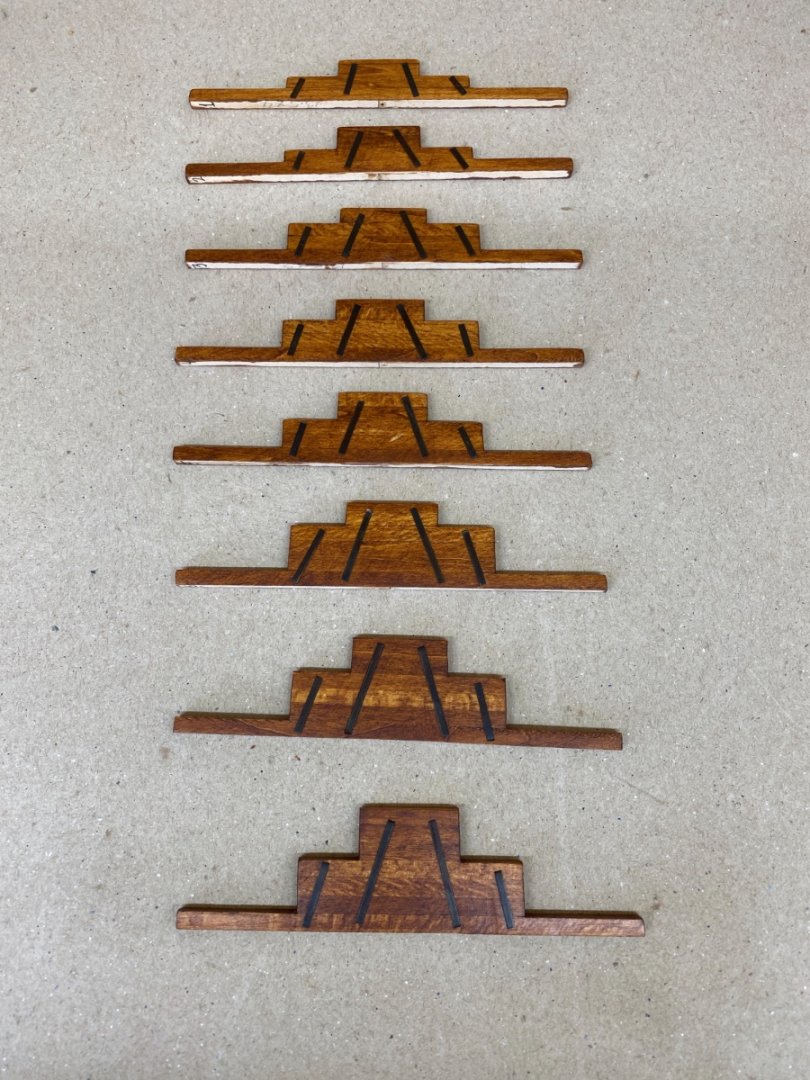
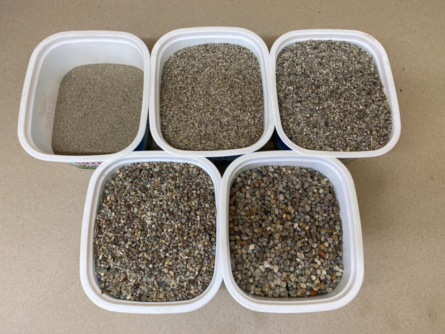
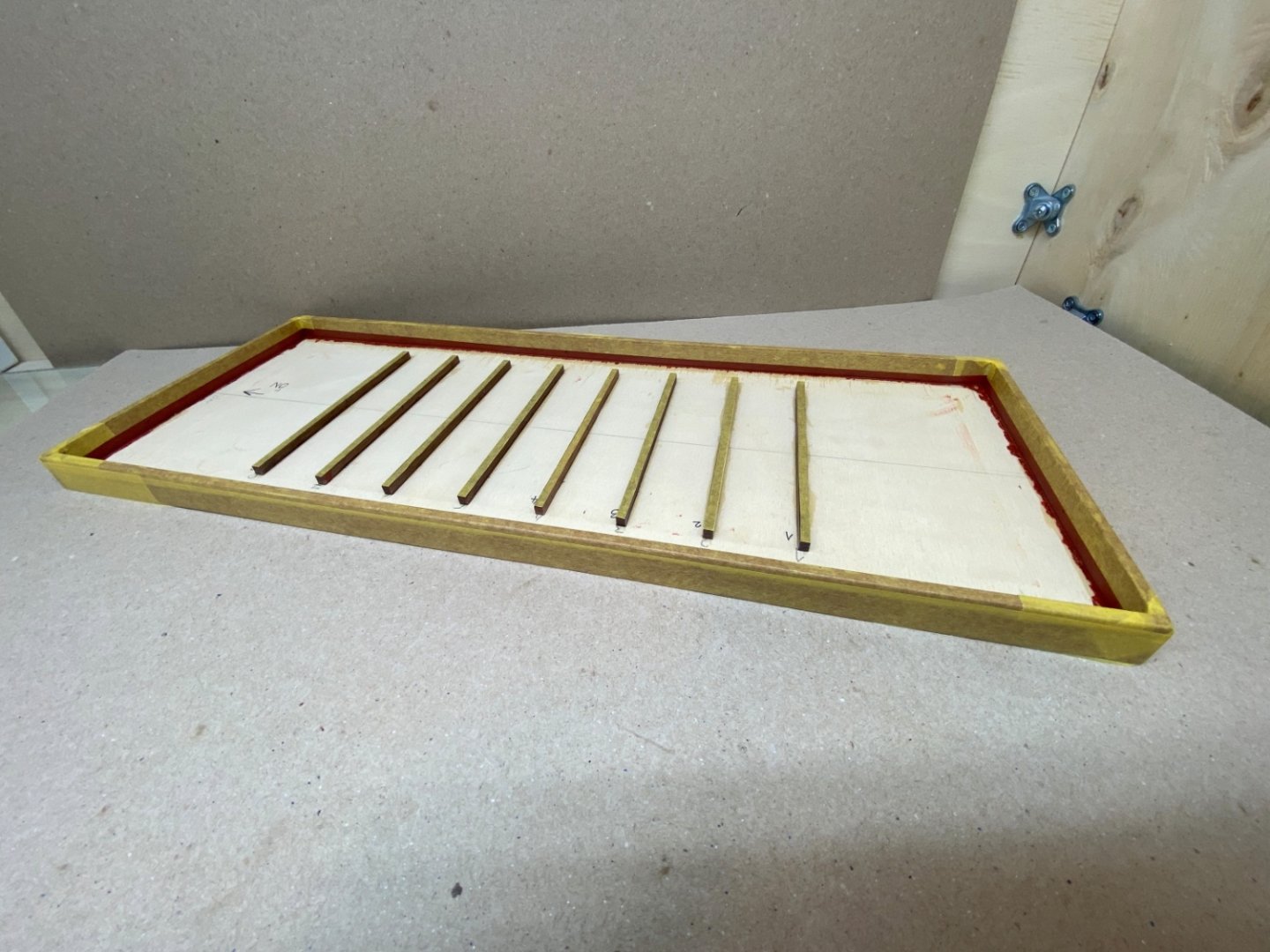
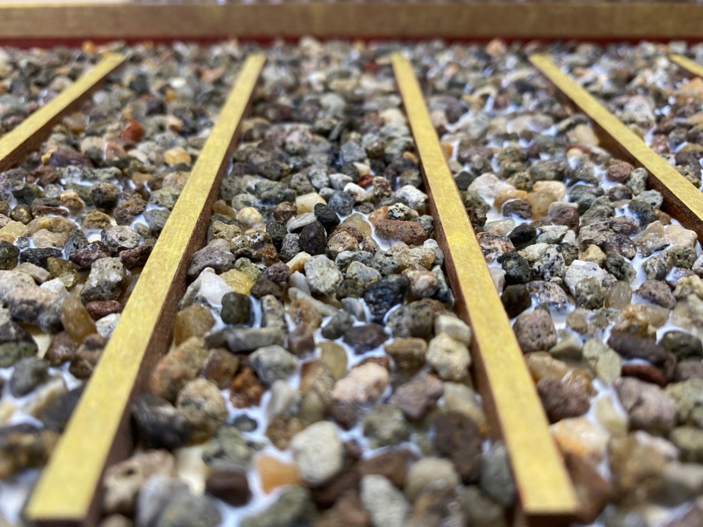
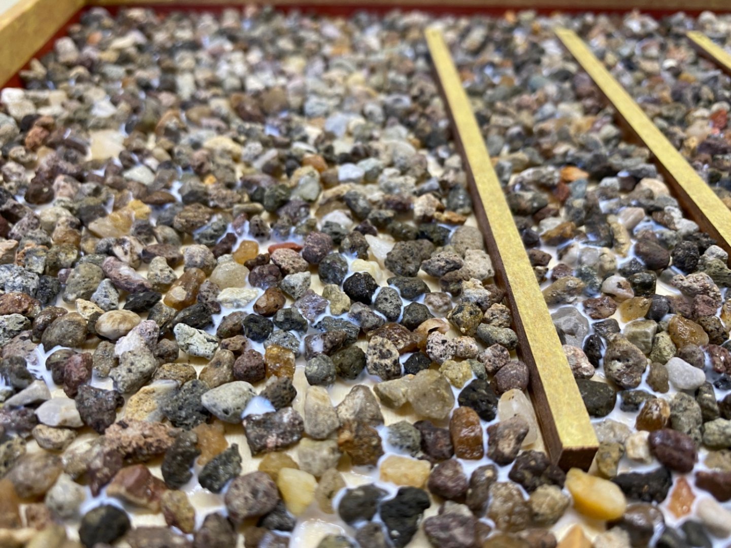
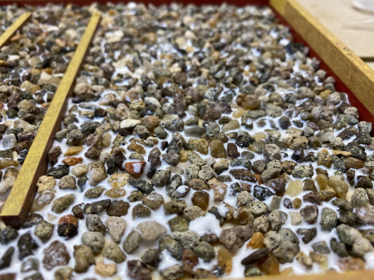
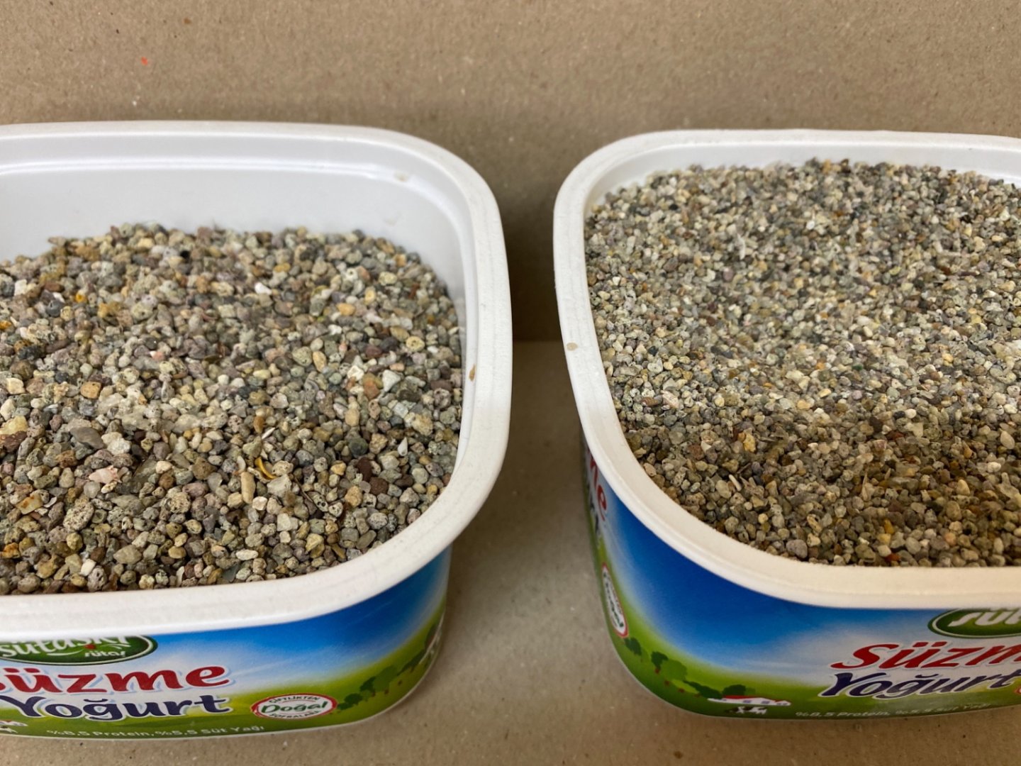
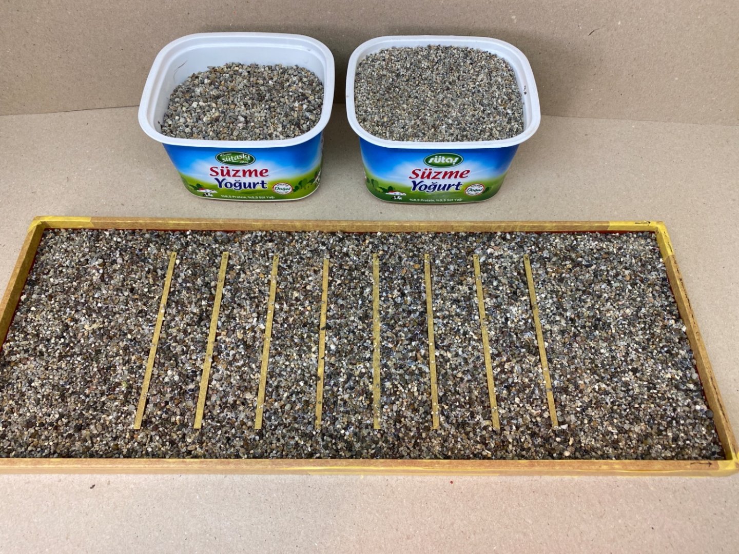
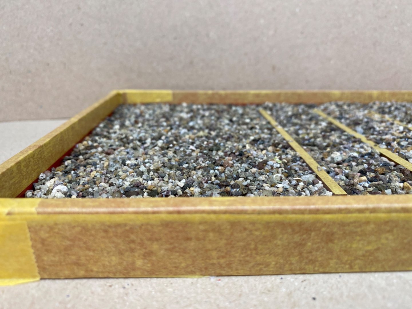
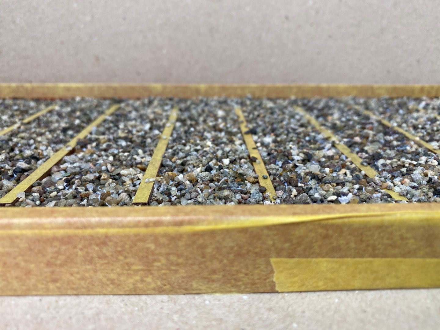
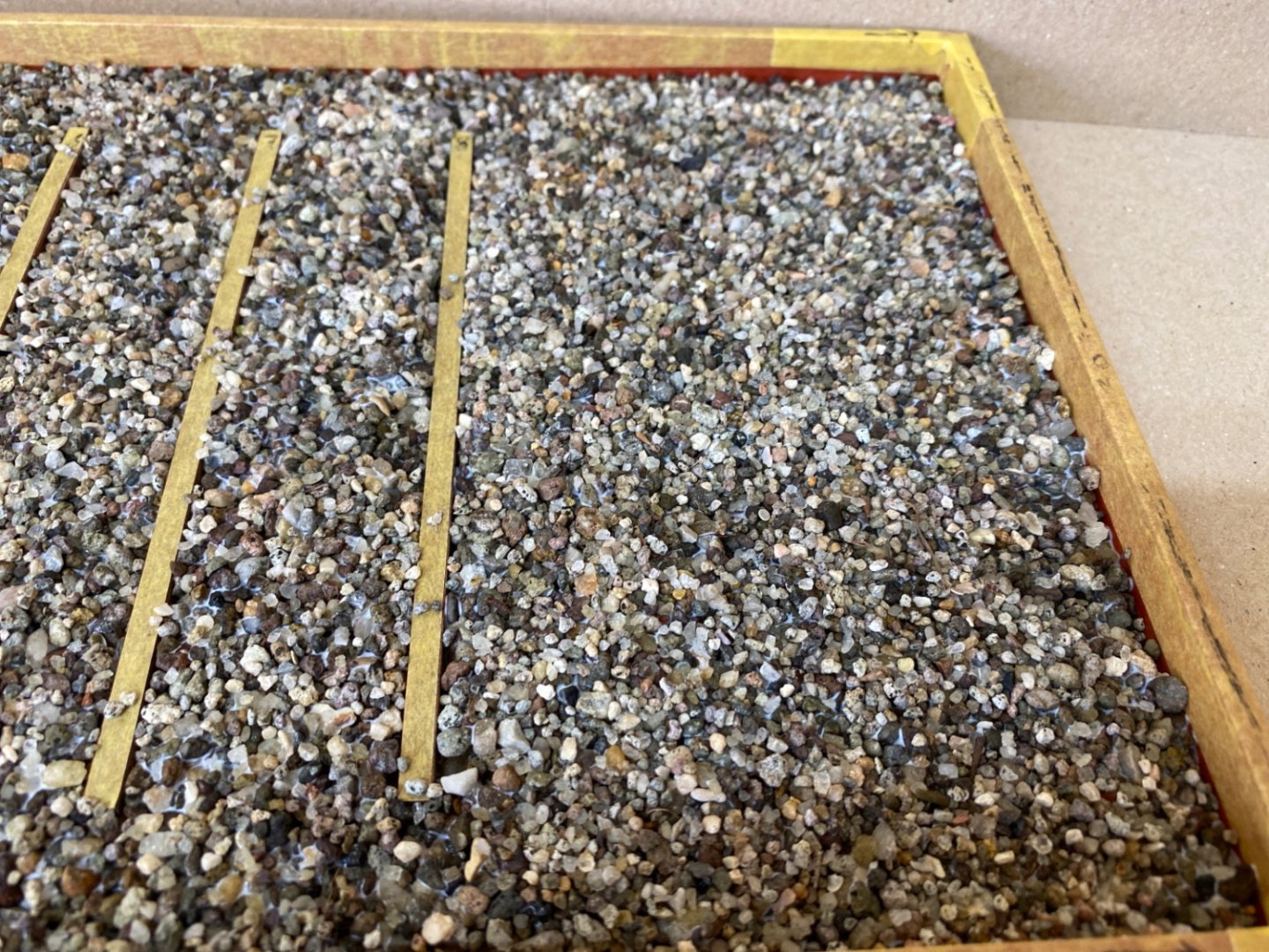
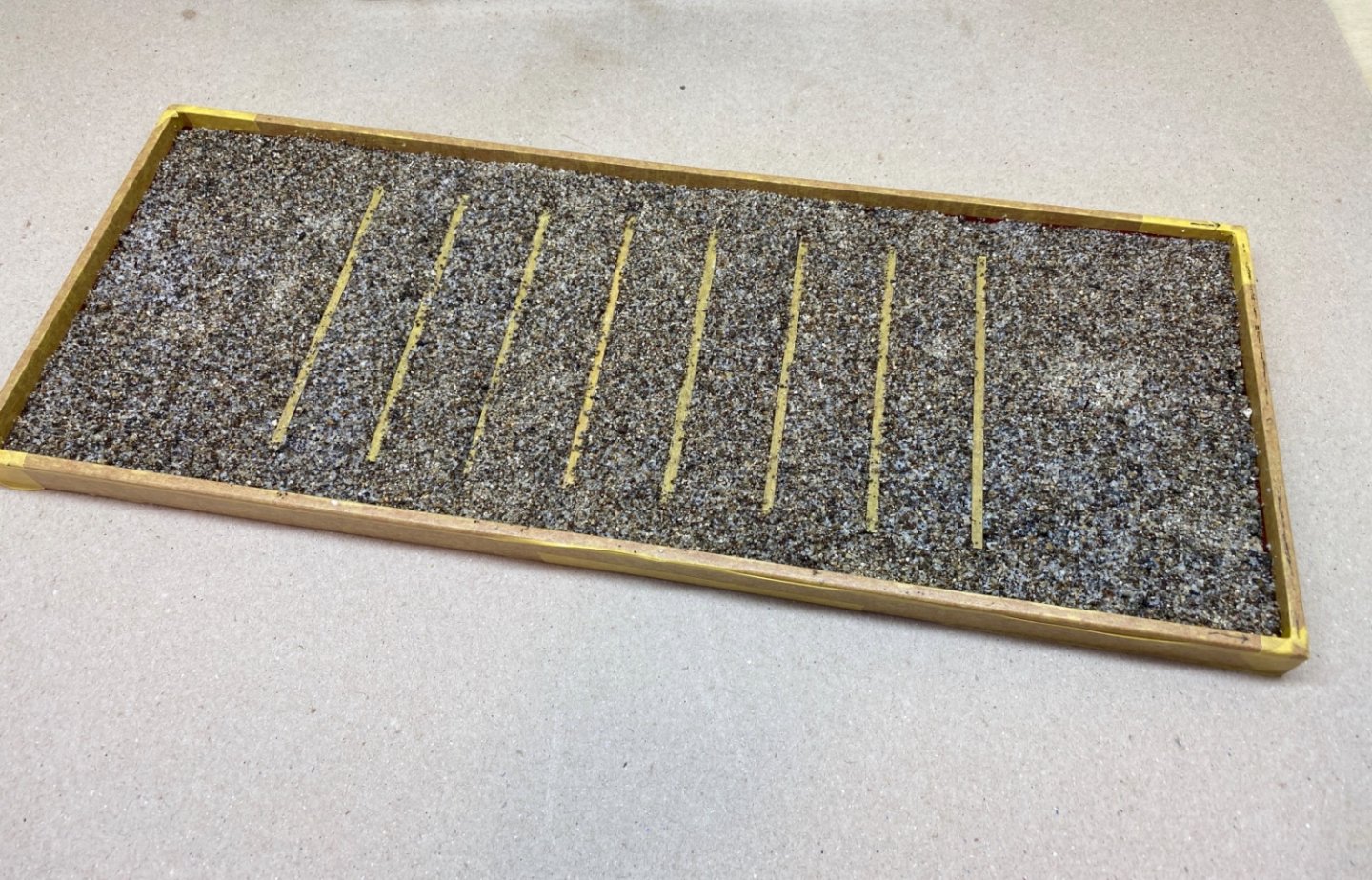
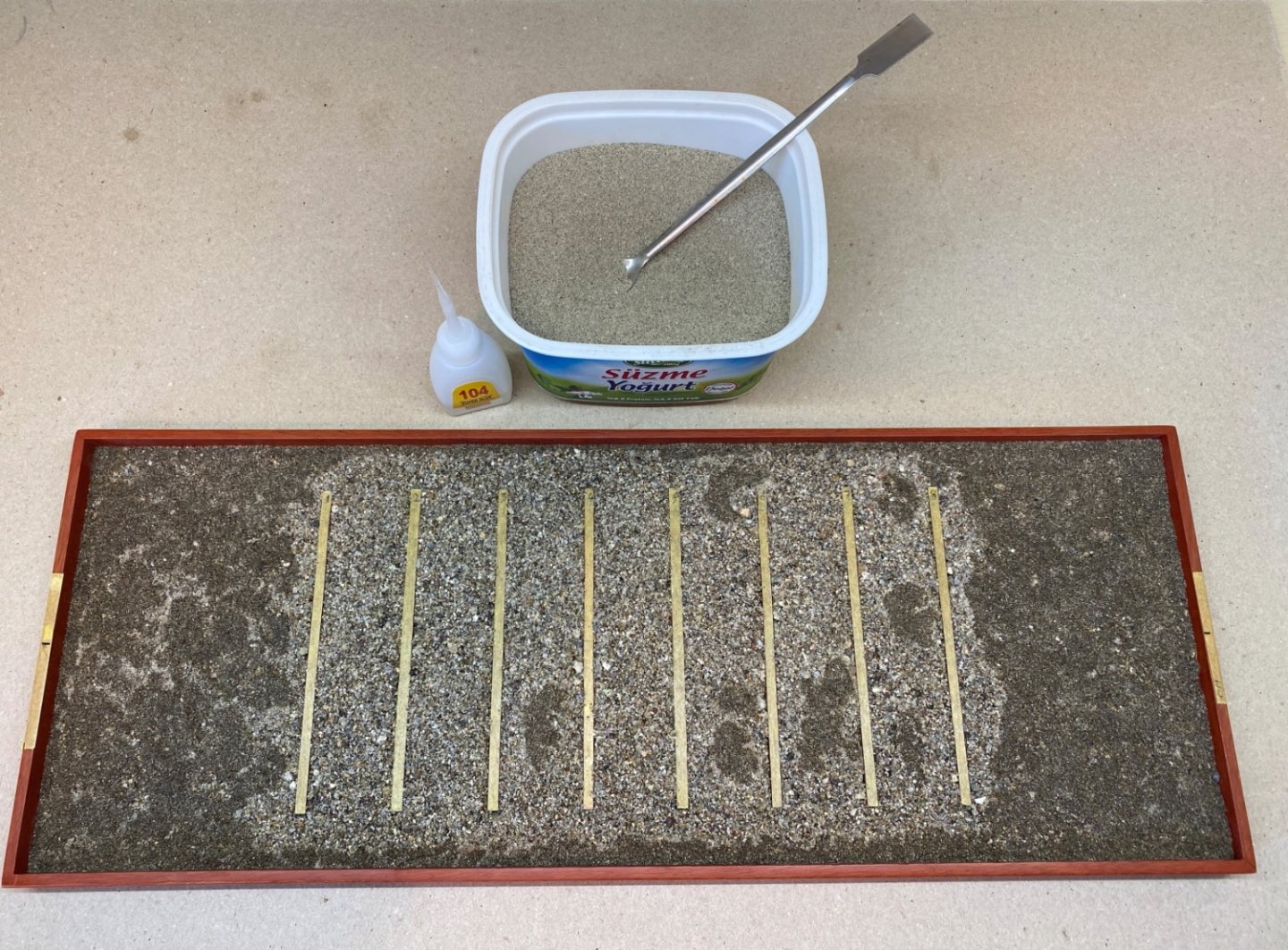
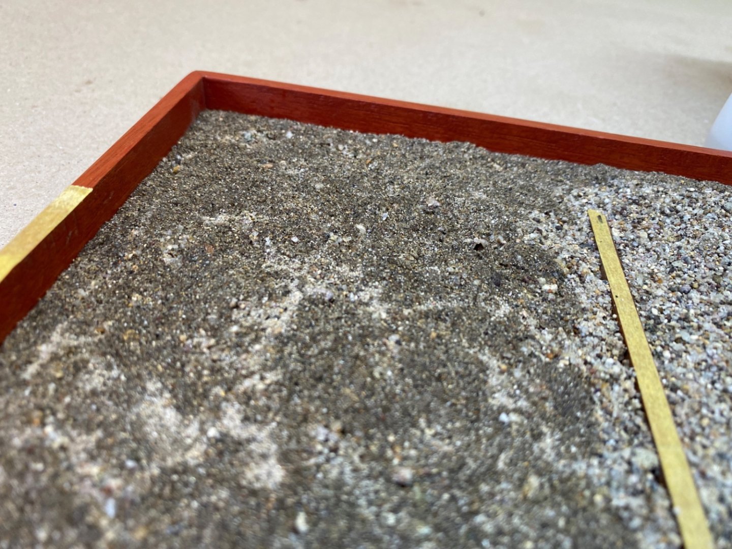
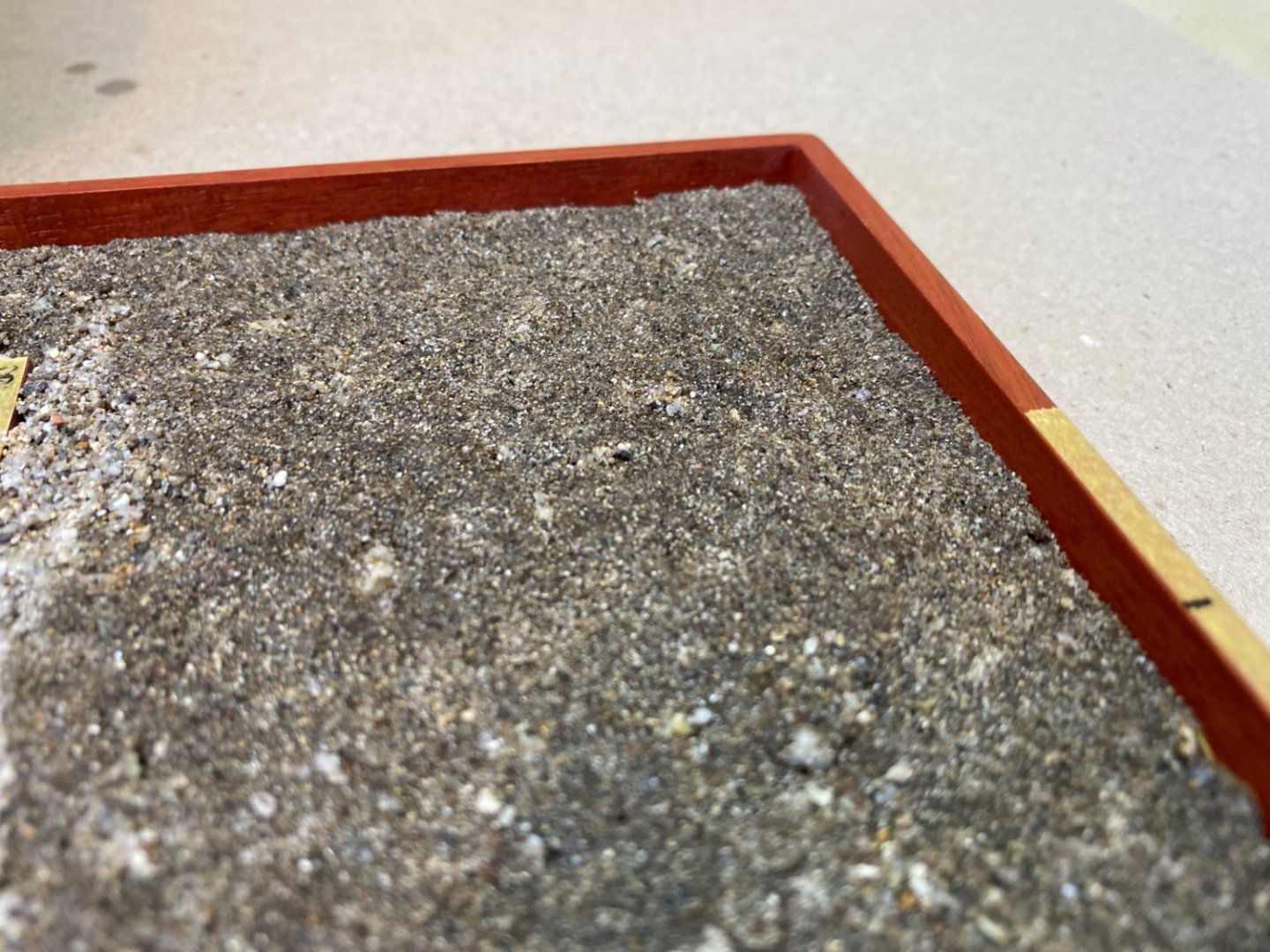
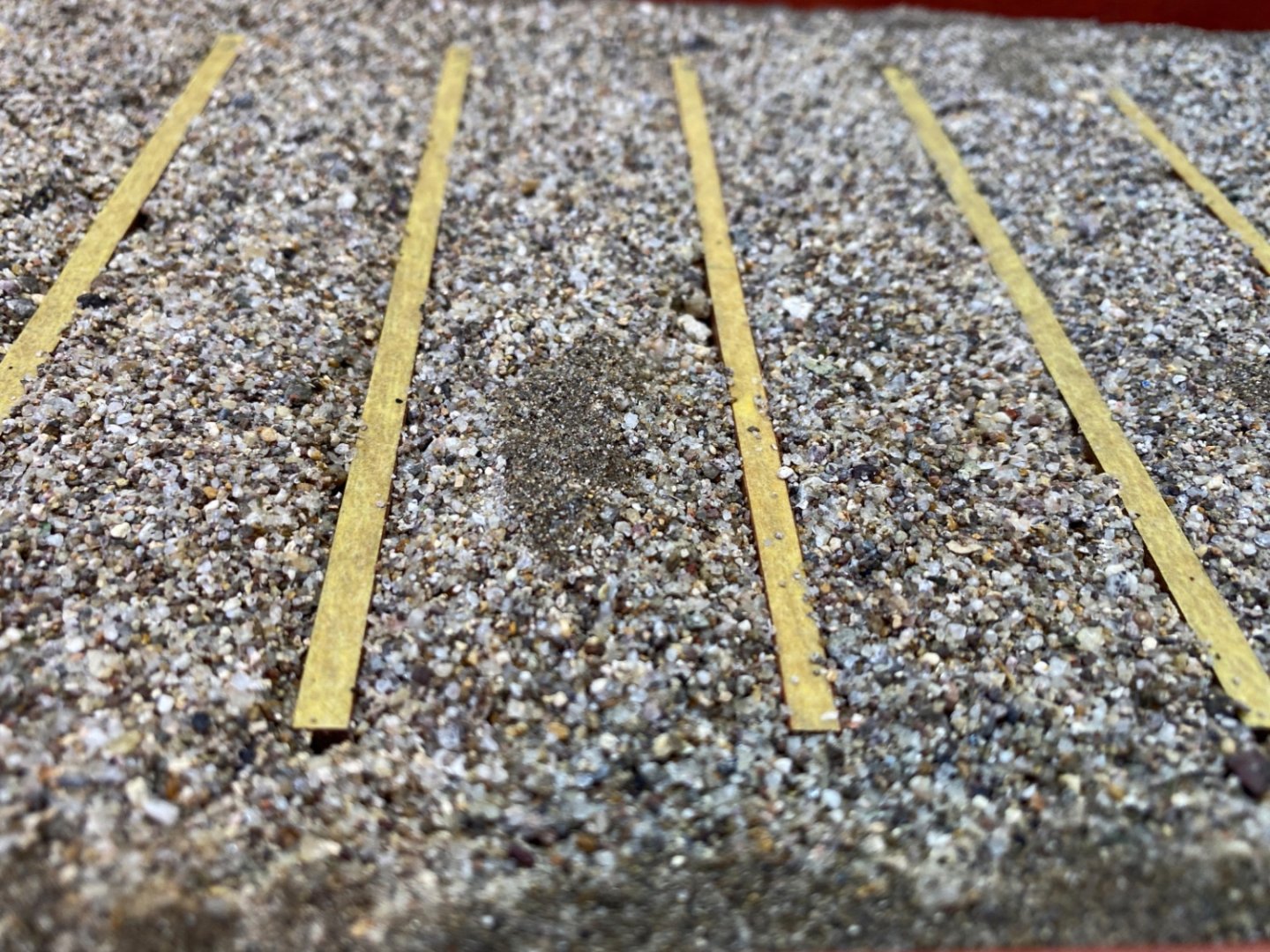
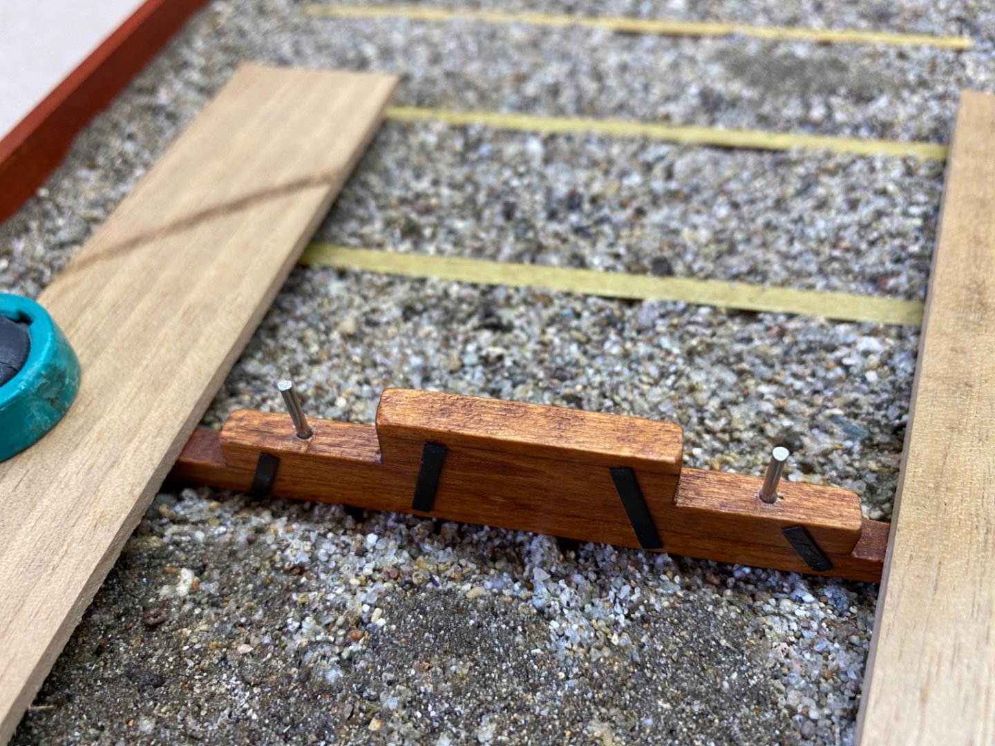
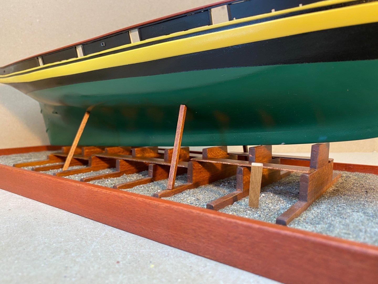
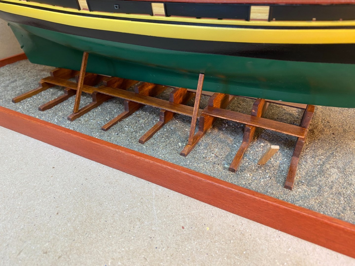
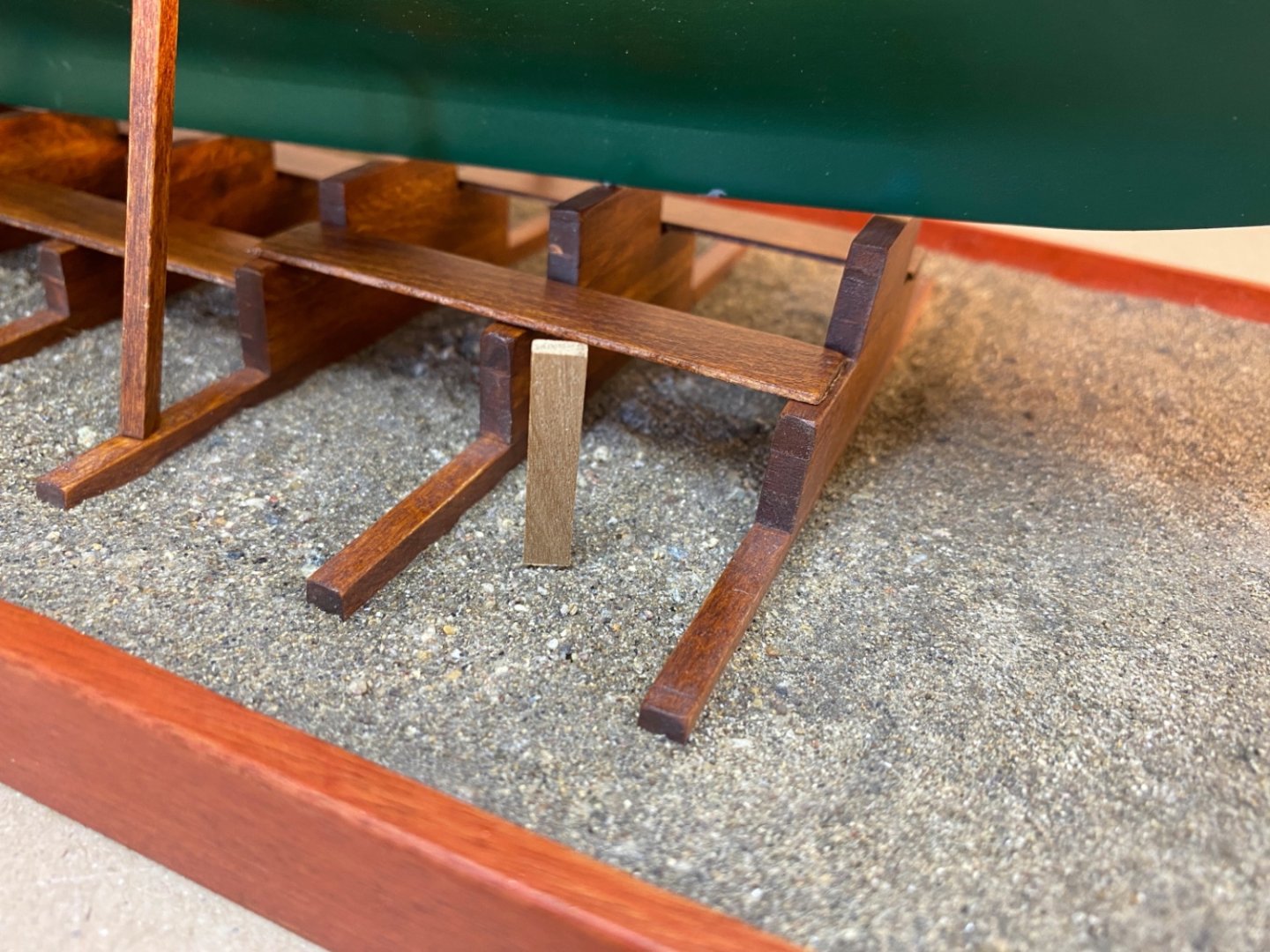
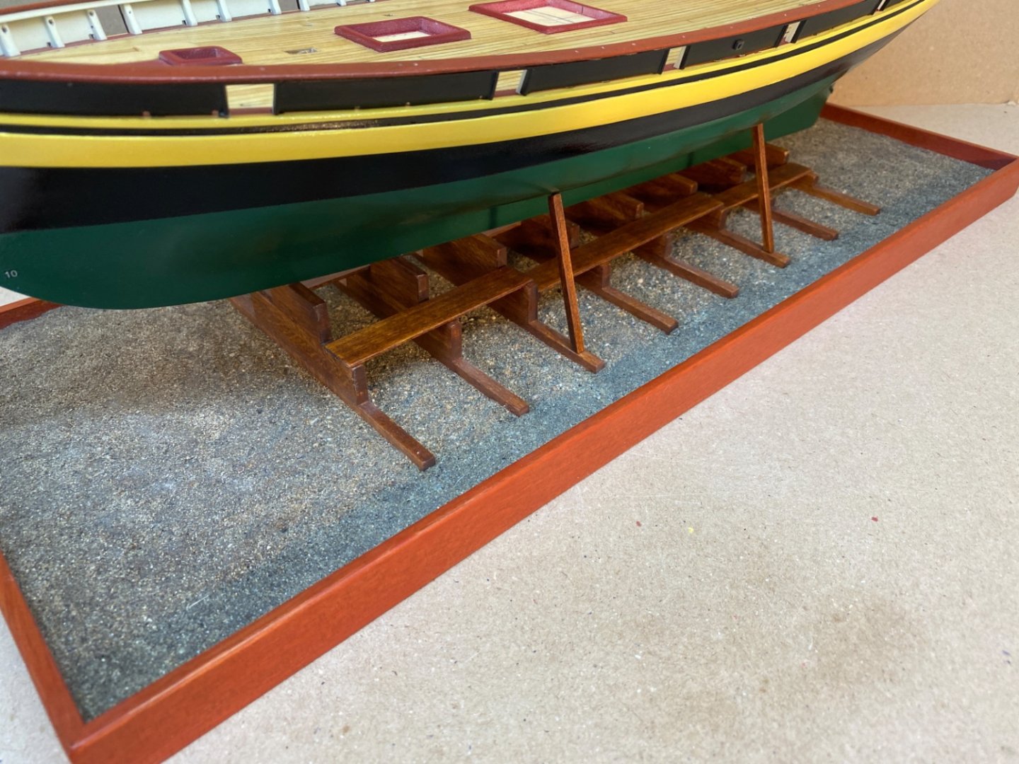
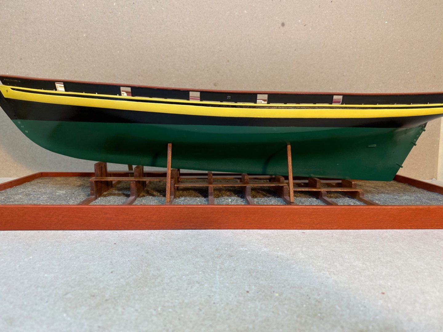
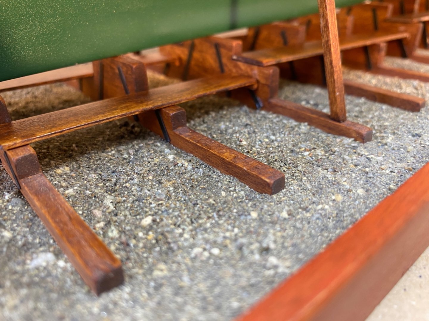
It is now March 2022 and the 19th month of the real build time. It was time to decide how the finished model be mounted. I chose to mount the model on building ways just like the original one in Baltimore. Mounting on building ways seemed to be an original and not-frequently-seen idea. Also by doing so I would eliminate the need for open sails which was an intimidating job for me as this was my first model with sails. So I started with preparing a 0.11 inch (2.7 mm) thick plywood with 6.8 x 18.7 inch ( 17.3 x 47.5 cm) width and length measurements. These measurements were smaller than the kit's dictation ( 9 x 24 inches) , but the one I planned was not the final base board and it will rest on a larger wood base with a glass/plexiglass cover on it. There are 8 rows of support blocks. The lines for those rows and midline perpendicular to them were drawn on the board. Initially I planned to use pine wood ( 2 x 15 mm ) as the sides of the baseboard. I cut 8 pieces of manzonia wood 2 x 2 mm sized, to be used as false ground timbers. These wood strips will level with the ground material before the real ! ground timbers and support blocks were installed. The support blocks are basswood 2x2 mm strips. Their number of tiers increase from 2 to 6, from aft to fore. They are temporarily mounted on 1 cm photo blocks. The support pin holes at the 2nd and 7th rows were drilled. Their corresponding places on the model's keel were marked and drilled. Pins were inserted and the first dry fitting test was done. After this dry fitting test the support blocks to be sanded and shimmed were noted as the model’s LWL must be parallel to baseline. I chose hazelnut stain for the finish on basswood support blocks. At this stage I changed my mind and decided to use 5 x 15 mm ( 3/16 x 2/5 inch) mahogany strips as side walls of the base board. The support blocks were stained and the false ground timbers were glued also. Mahogany stain was applied followed by two coats of sanding sealer and two coats of clear matt varnish. The same sequence was applied to the support blocks. Metal ties were glued to the support blocks. It was time to decide what to use as ground material. Living by the seaside and having nice sandy beaches, I decided to use sand as the ground material. After collecting about two liters of sand from the beach, I used several different pore sized sieves (The final one was an old silk lady stocking) to categorise the sand into 5 sizes. I masked the mahogany side walls and the top sides of the false ground timbers. I started with the coarsest sand stones first. After applying white glue diluted with water with 1:1 ratio, I started to place the stones as the first layer of the ground material. After 24 hours I continued with two smaller sized stones. I started to place them after I applied the diluted white glue on the first layer of stones. On the third day the thinnest sand was used. All the spaces were filled with this sand excluding the masked false ground timbers. The level was corrected by a dry cut brush. This time gap filling liquid CA was used to fix the thin sand layer. The color of the sand darkened by glue. As you can see in the photos below, the spaces between the false ground timbers were spared at this stage. It was now time to install the hazelnut stained support blocks. After gluing each row to the false ground timbers, I drilled 1.5 mm (1/16 inch) diameter holes on the support blocks , down to and including the plywood base, at points which later be covered by work platforms. I placed suitable sized nails with heads cut off. This was I planned to increase the sturdiness of the support blocks. After this stage I started to fill the spaces left open between the support blocks and the ground level with the thinnest sand. The space was filled, corrected by dry cut brush and CA was applied. This was repeated as much as the demand continued. However at the final application first CA was applied and thin sand was poured on. After 3-4 minutes unattached sand was removed , leaving the natural color attached ones. This was also repeated until a natural color sand was achieved everywhere. The walkways was finished with the work platforms and support struts. They were dry fitted with the model. The work platforms and support struts were not installed at this time. However the model was kept on the building ways until the end except removal for satin coat application.


- 114 replies
-
- 5
-
-
-
- Pride of Baltimore II
- Model Shipways
- (and 1 more)
-
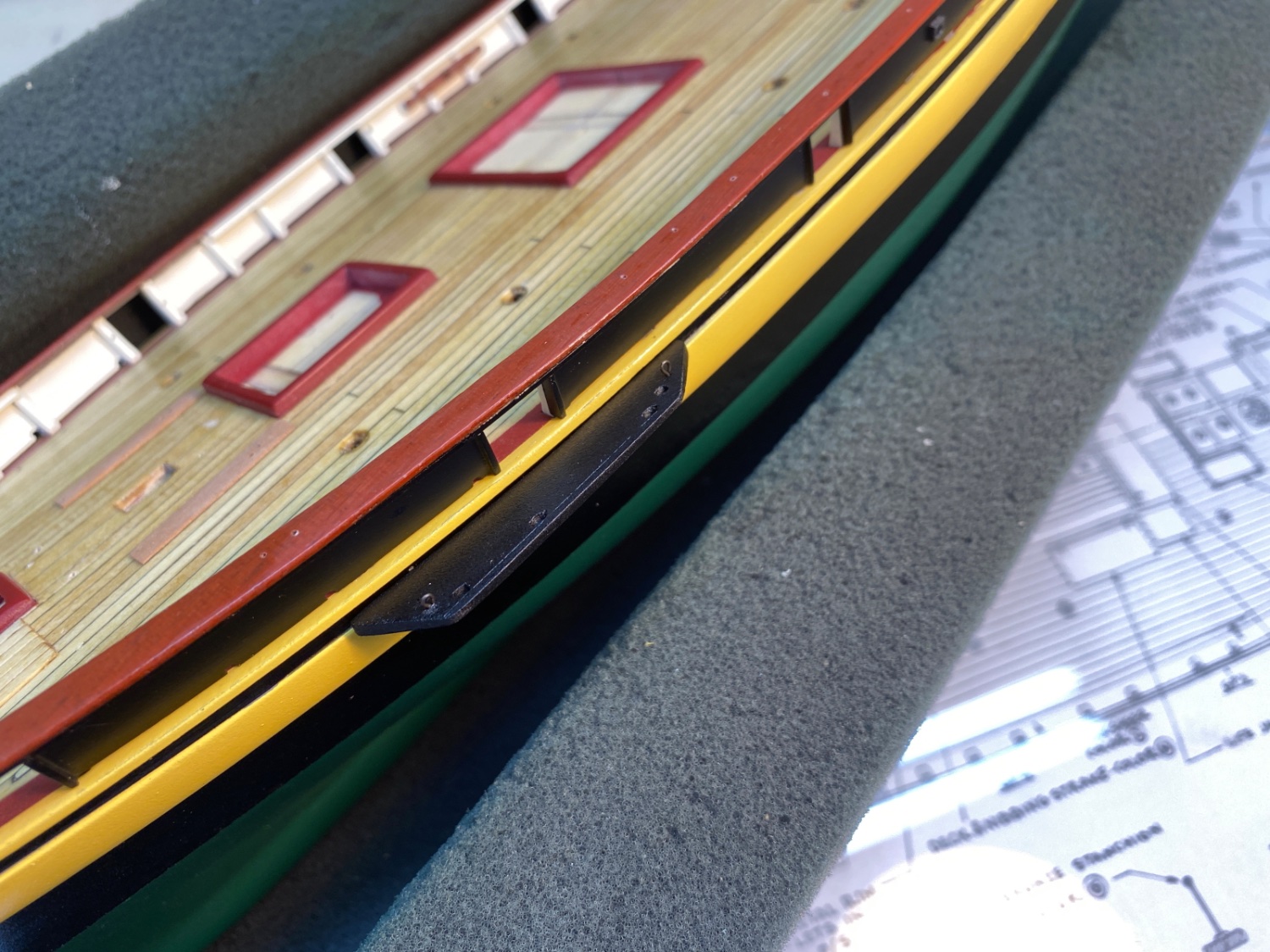
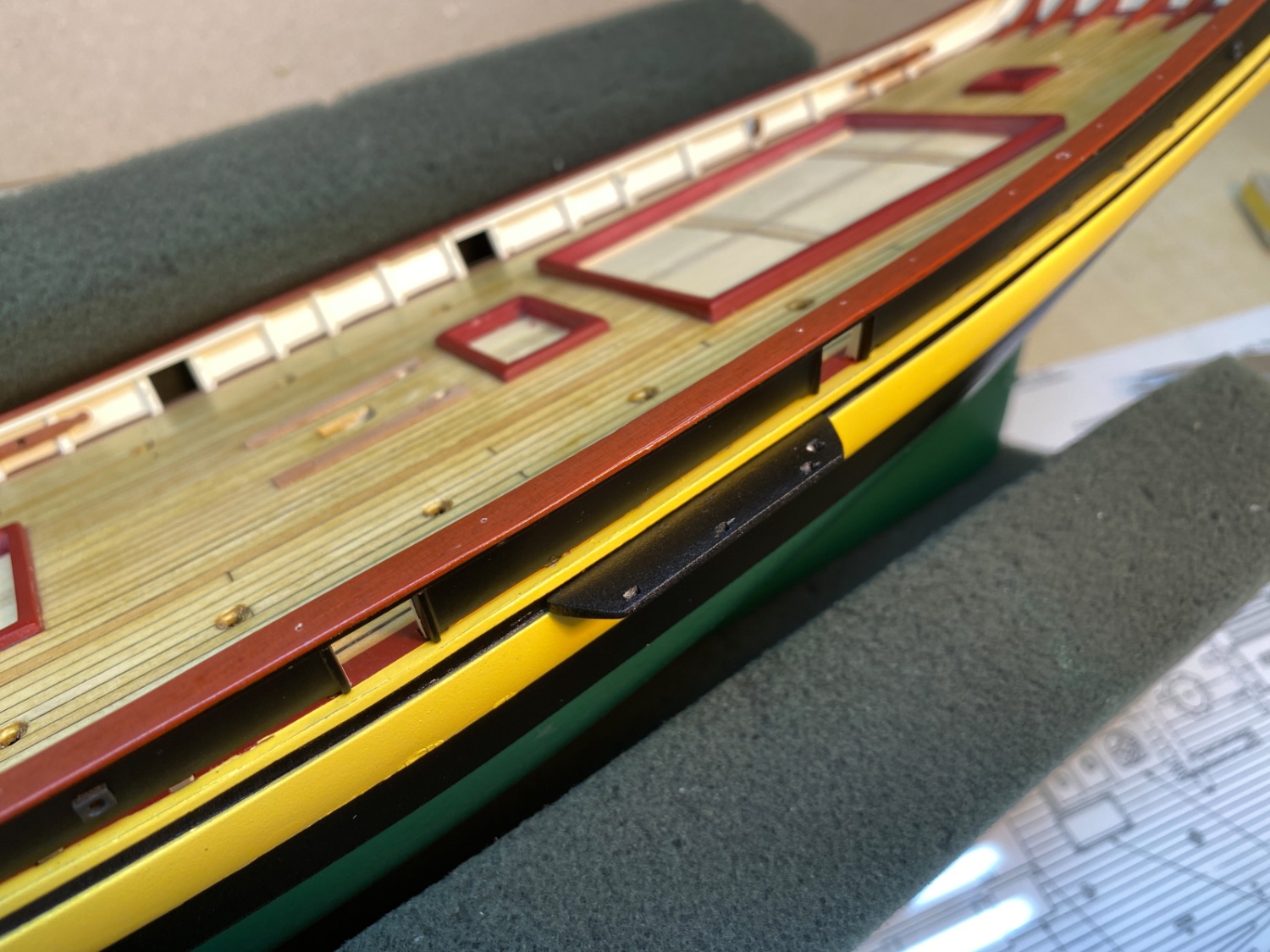
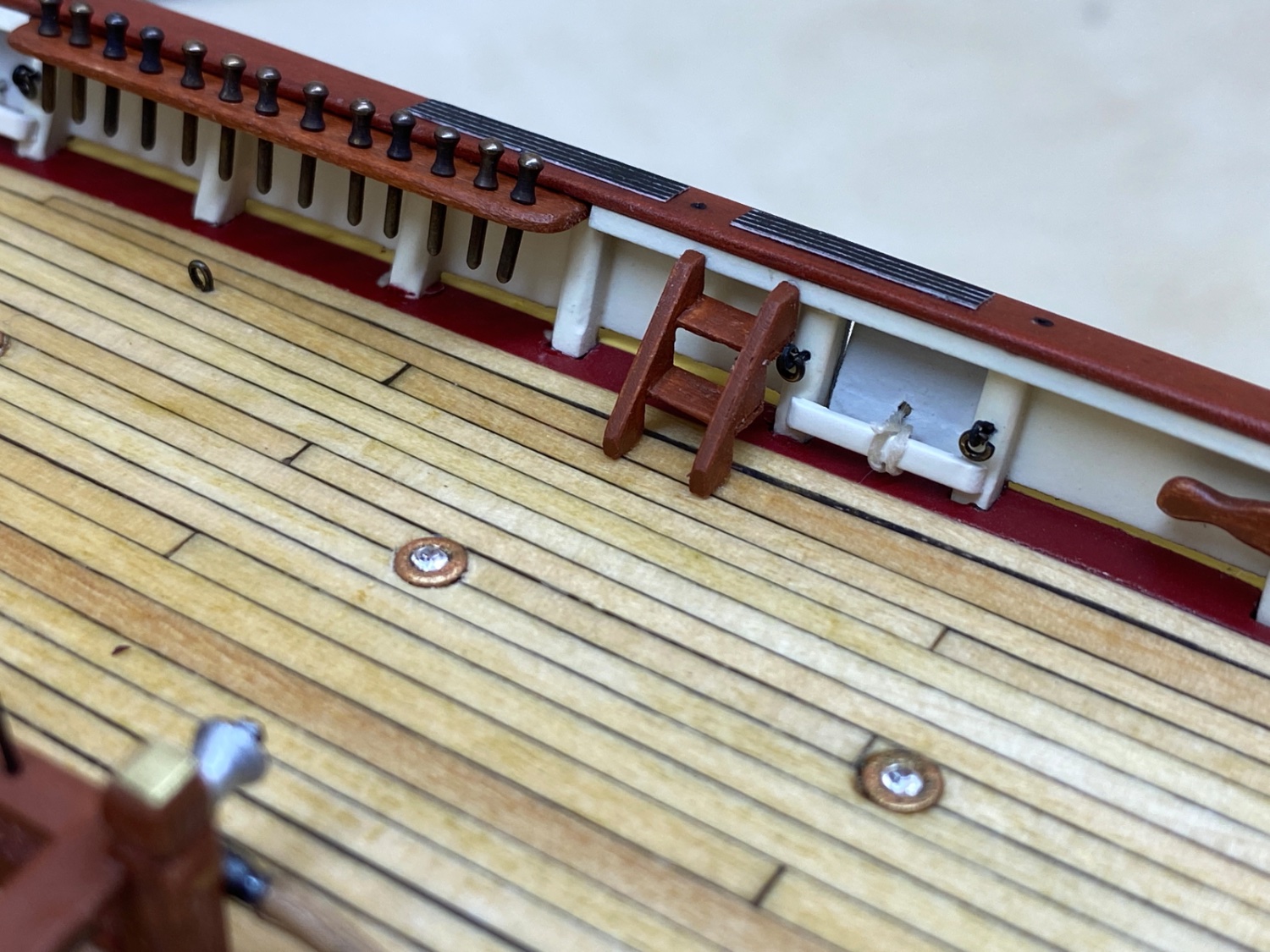
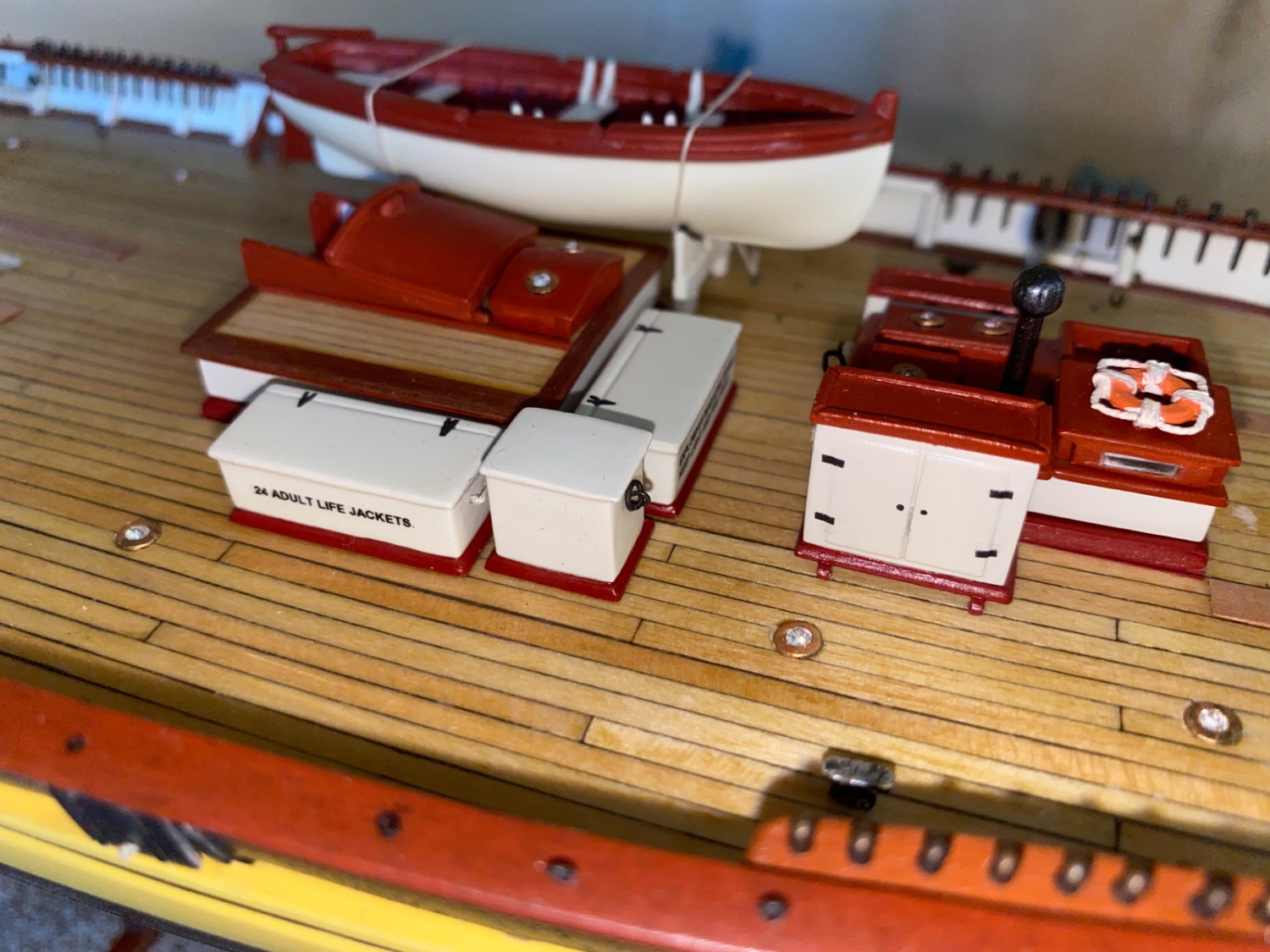
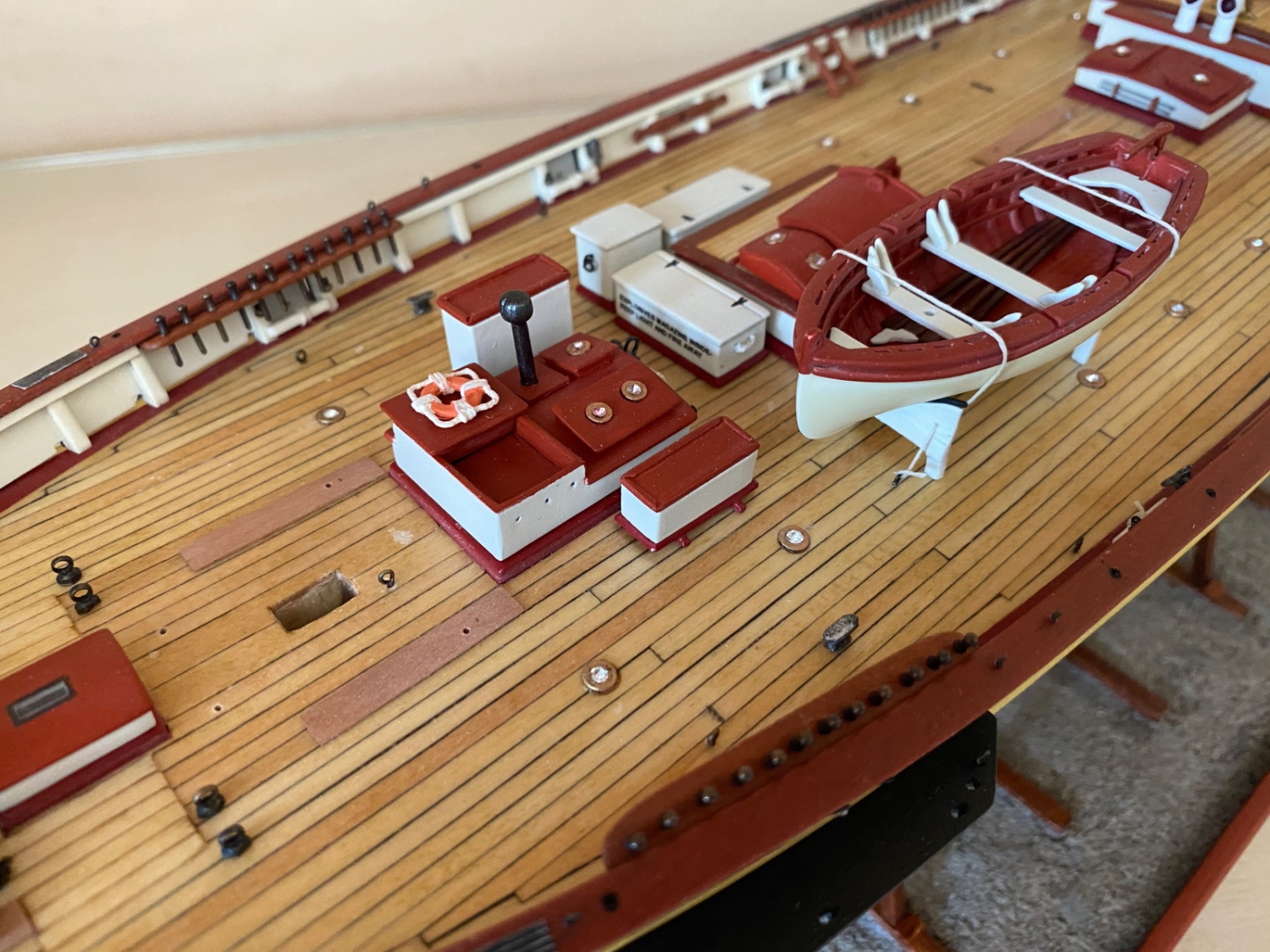
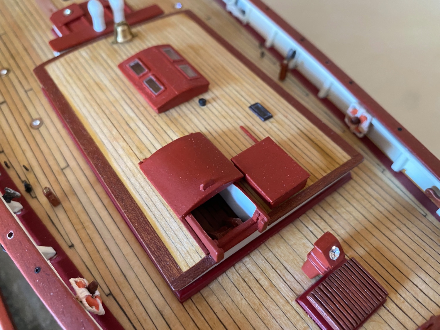
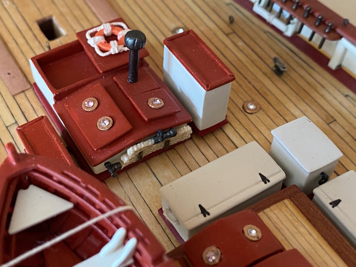
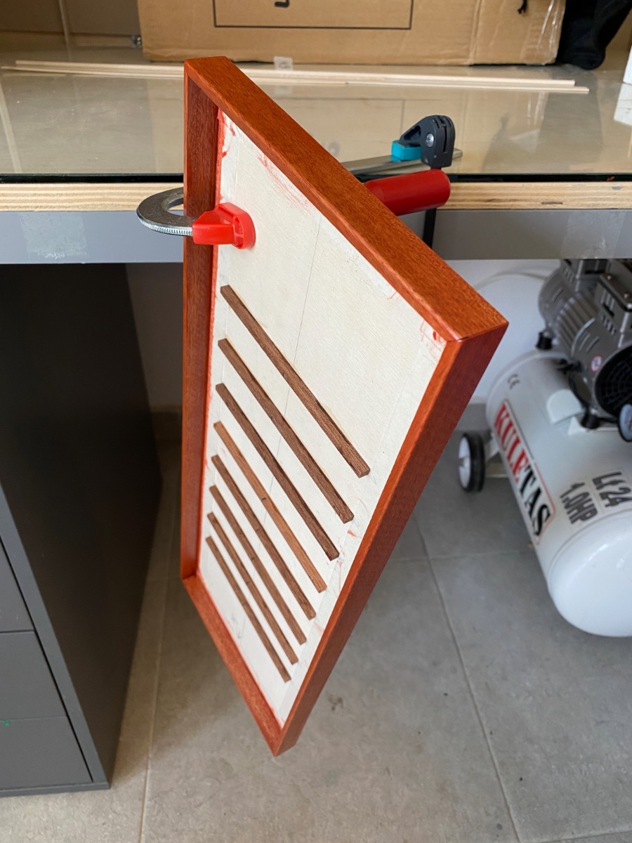
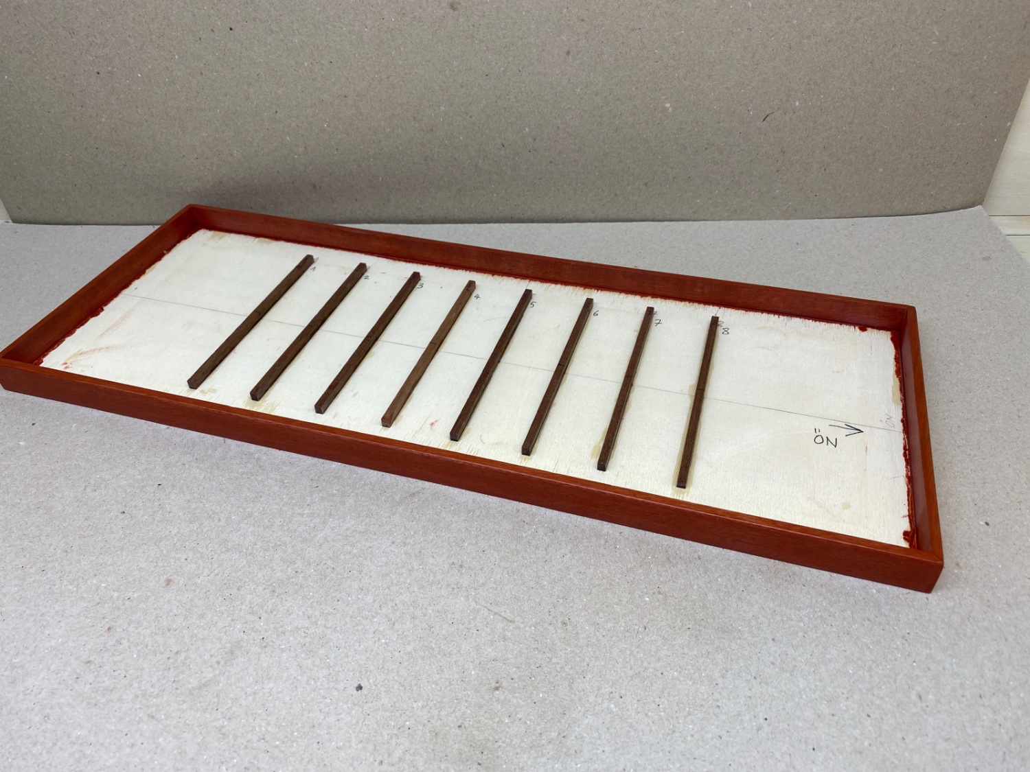
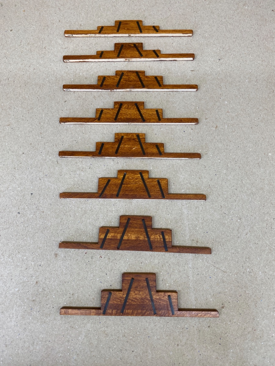
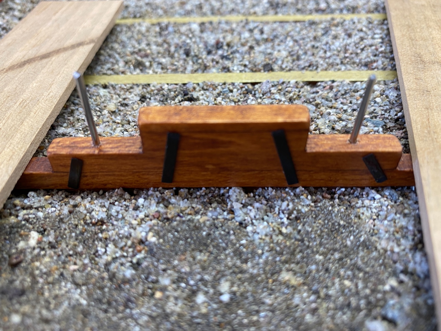
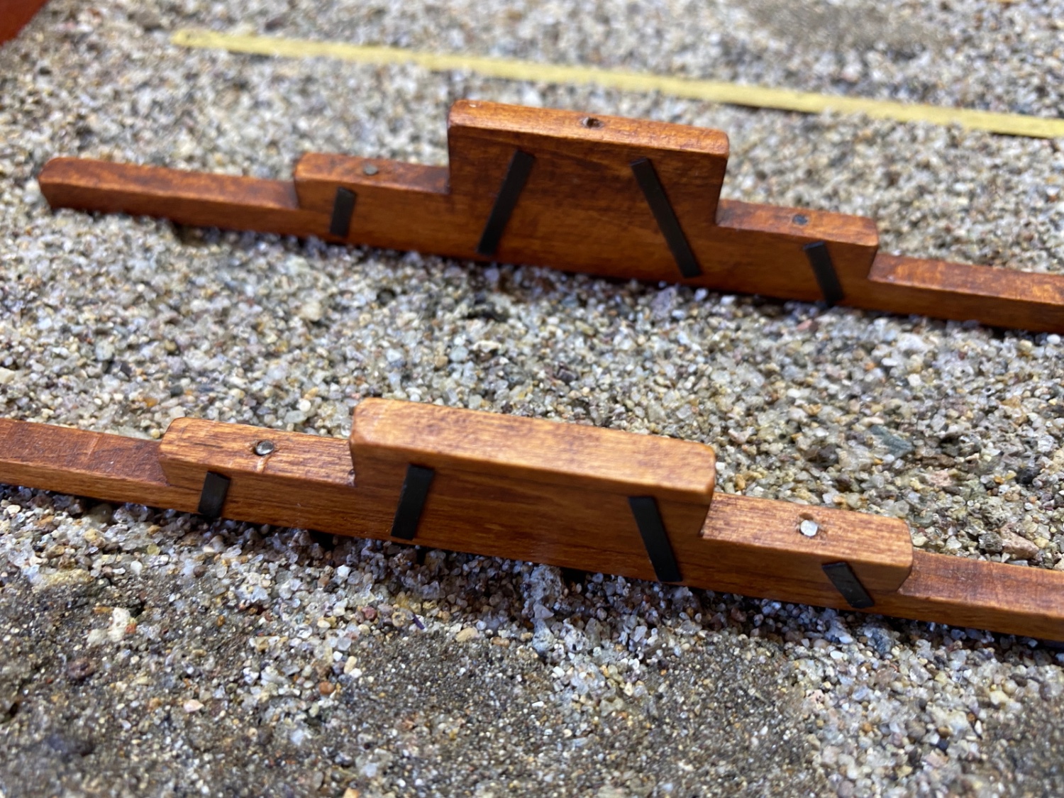
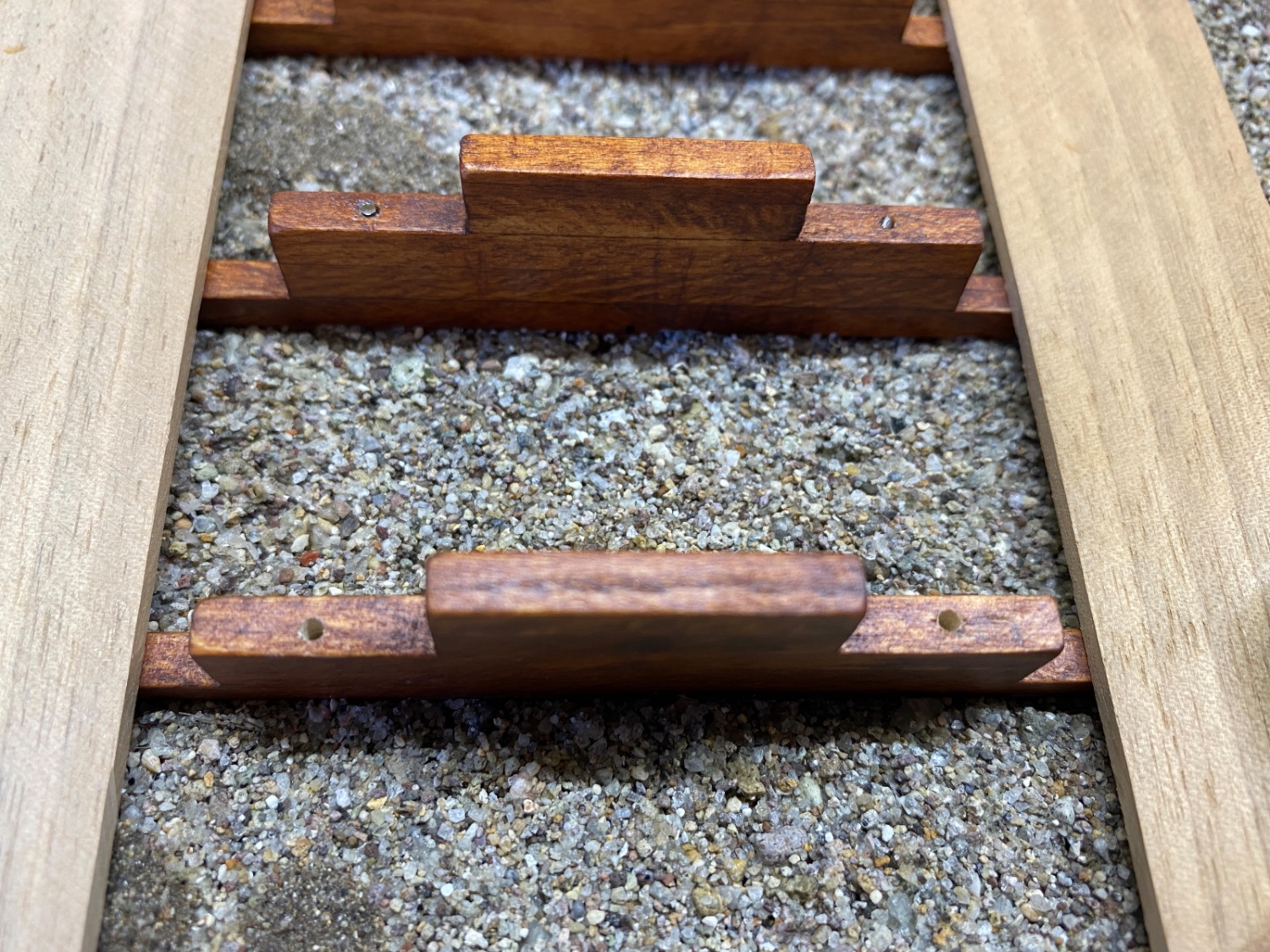
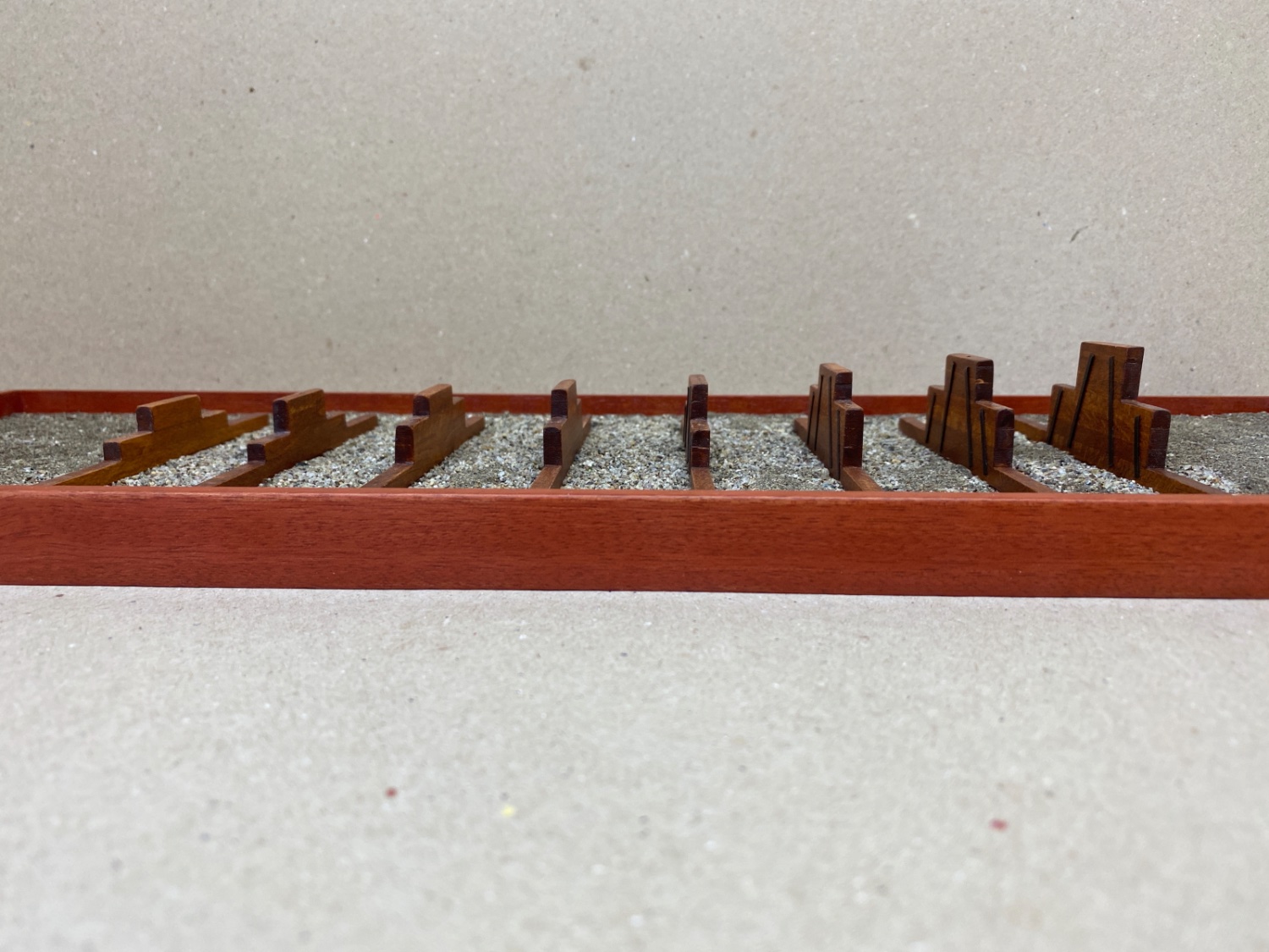
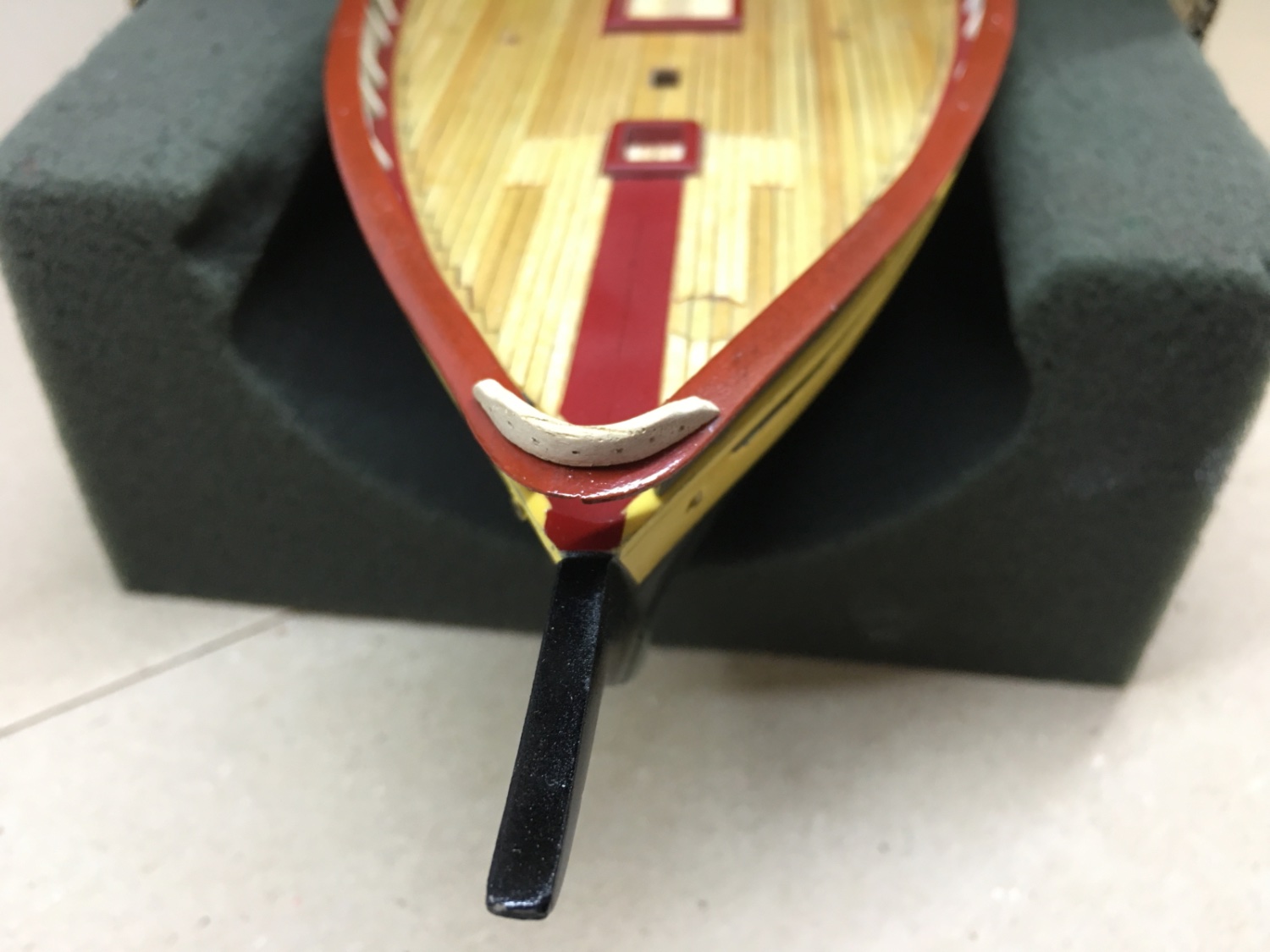
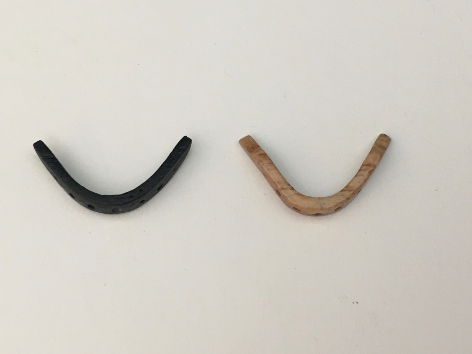
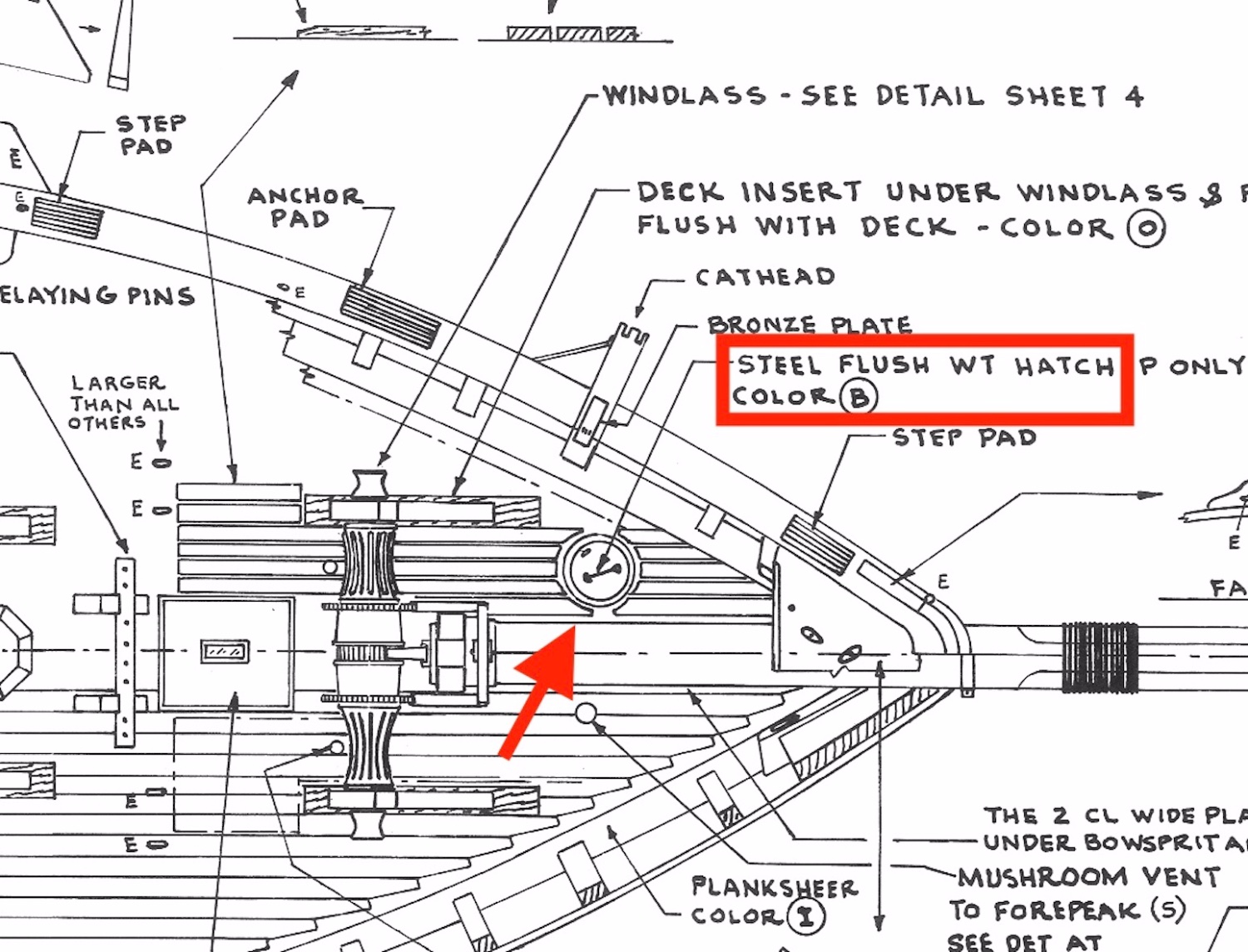
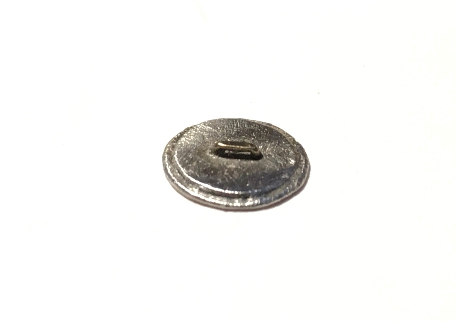
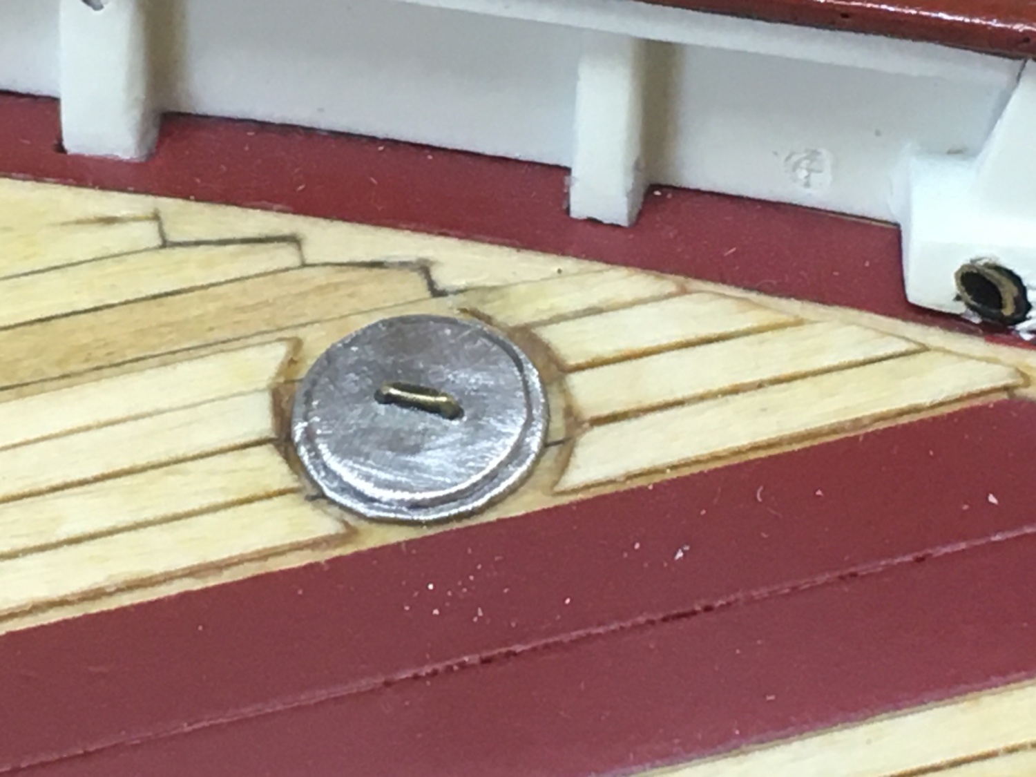
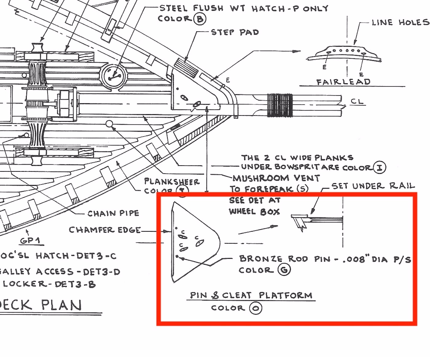
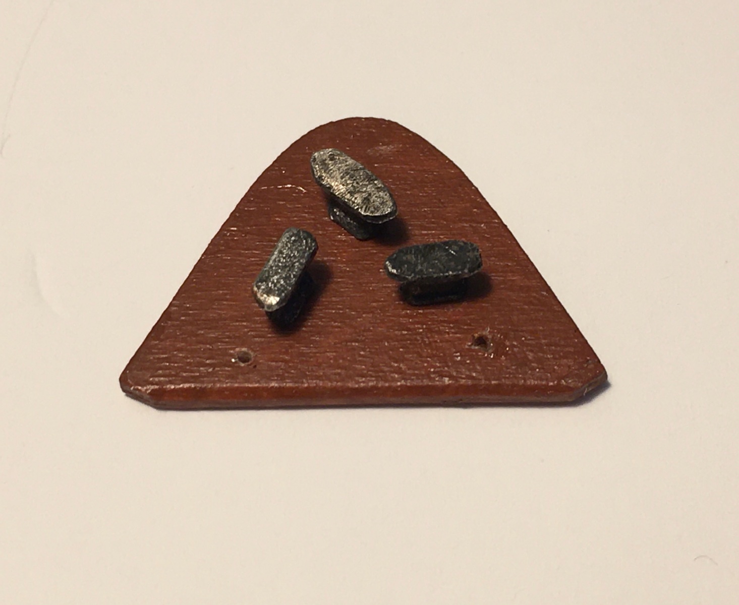
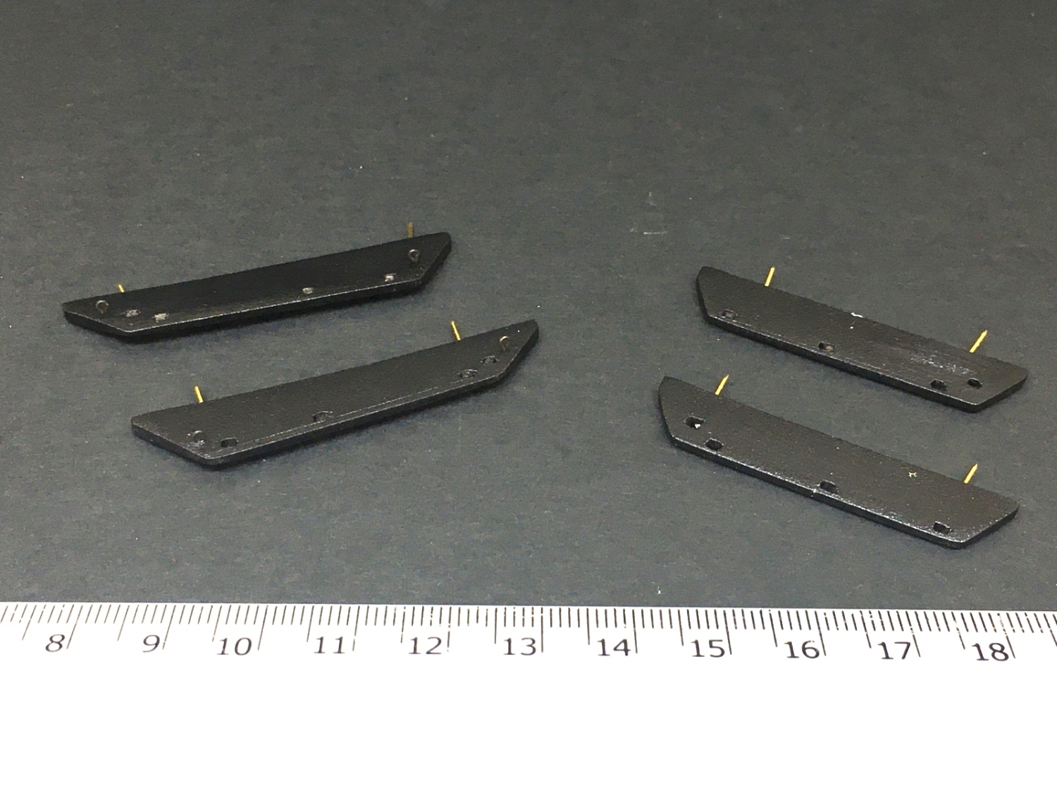
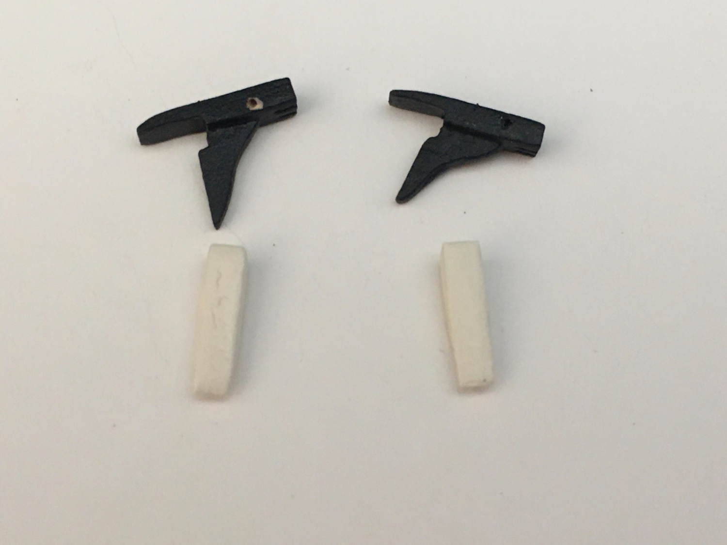
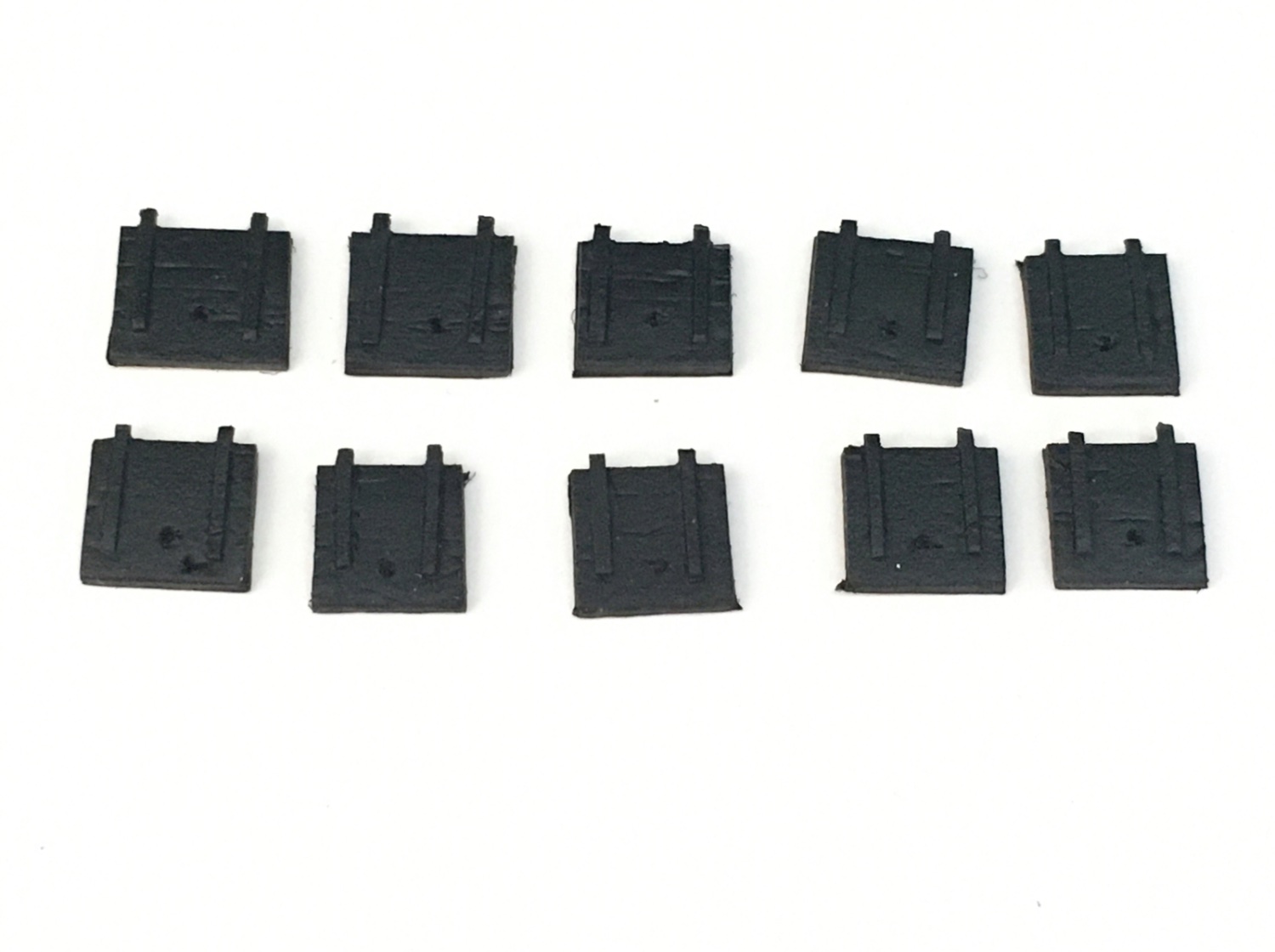
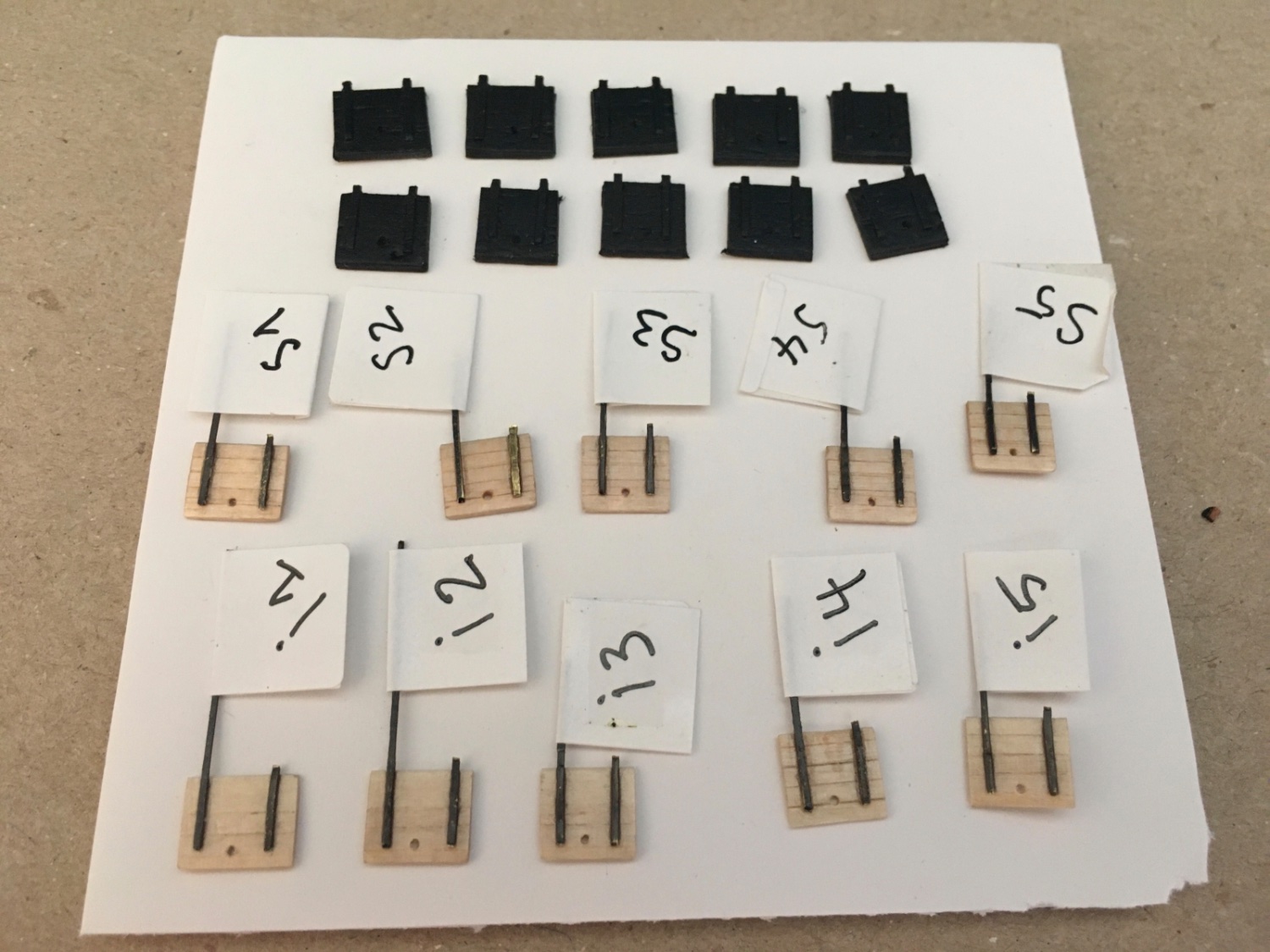
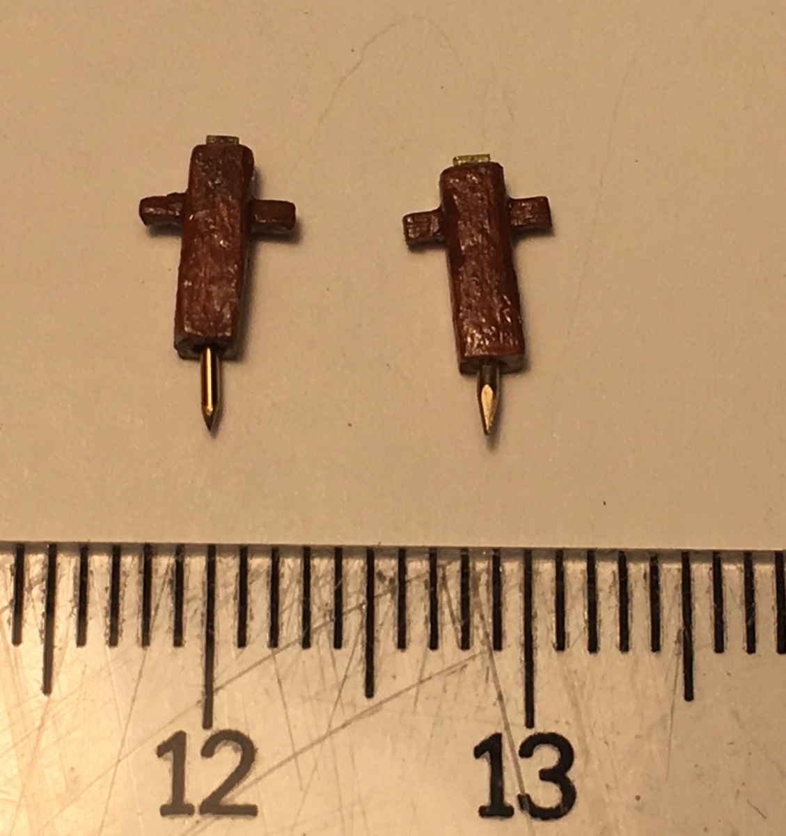
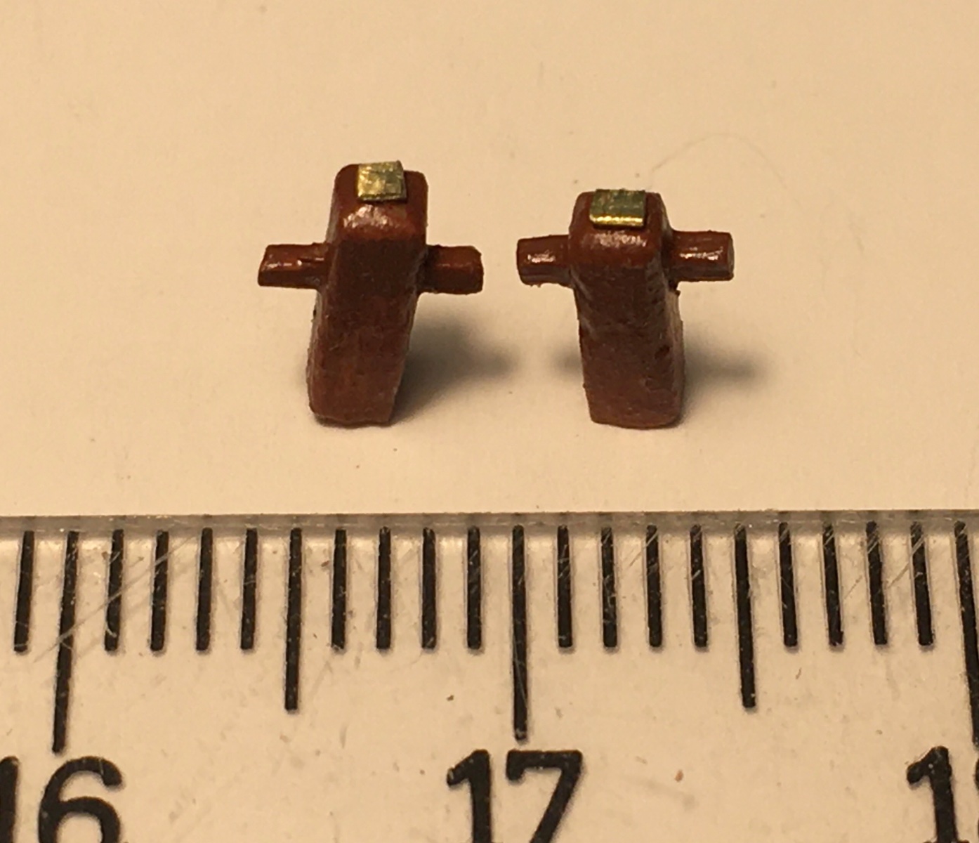
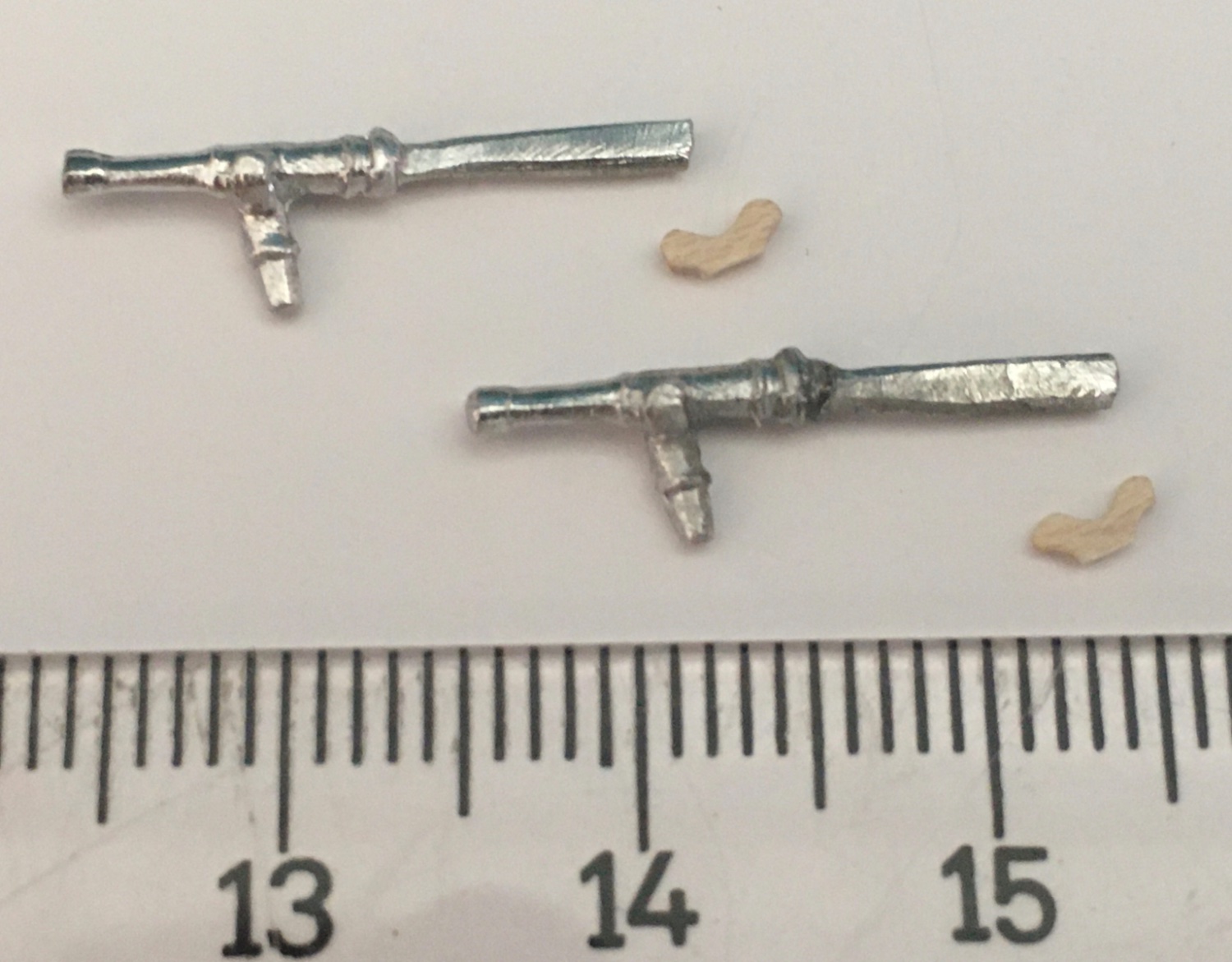
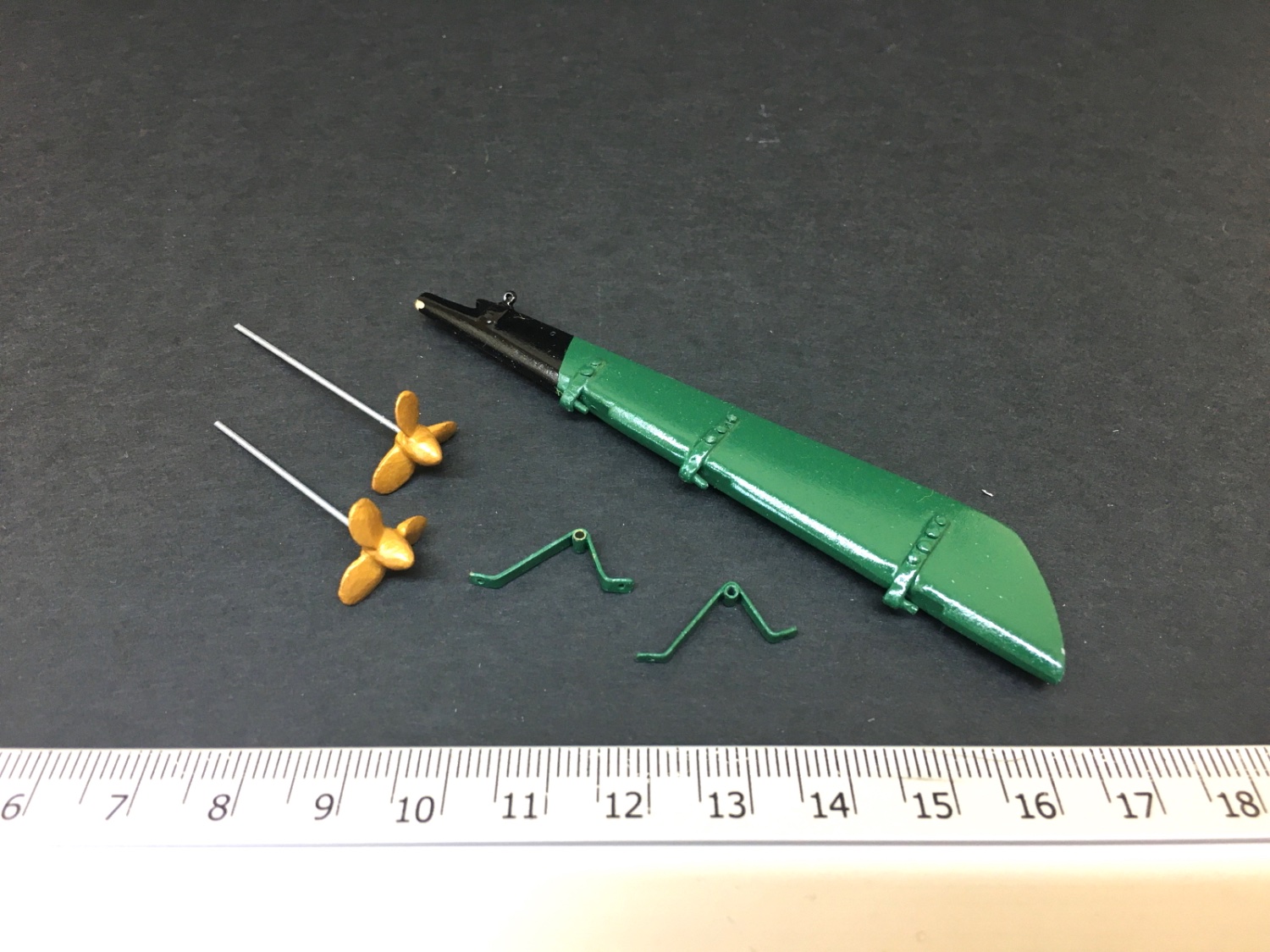
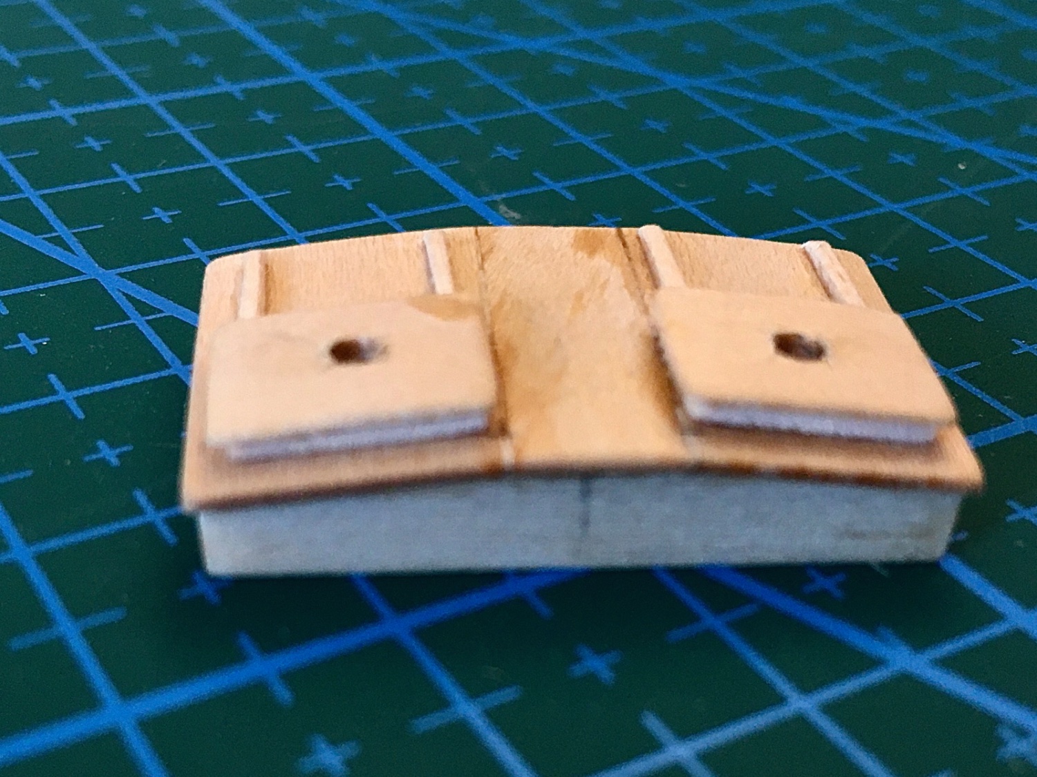
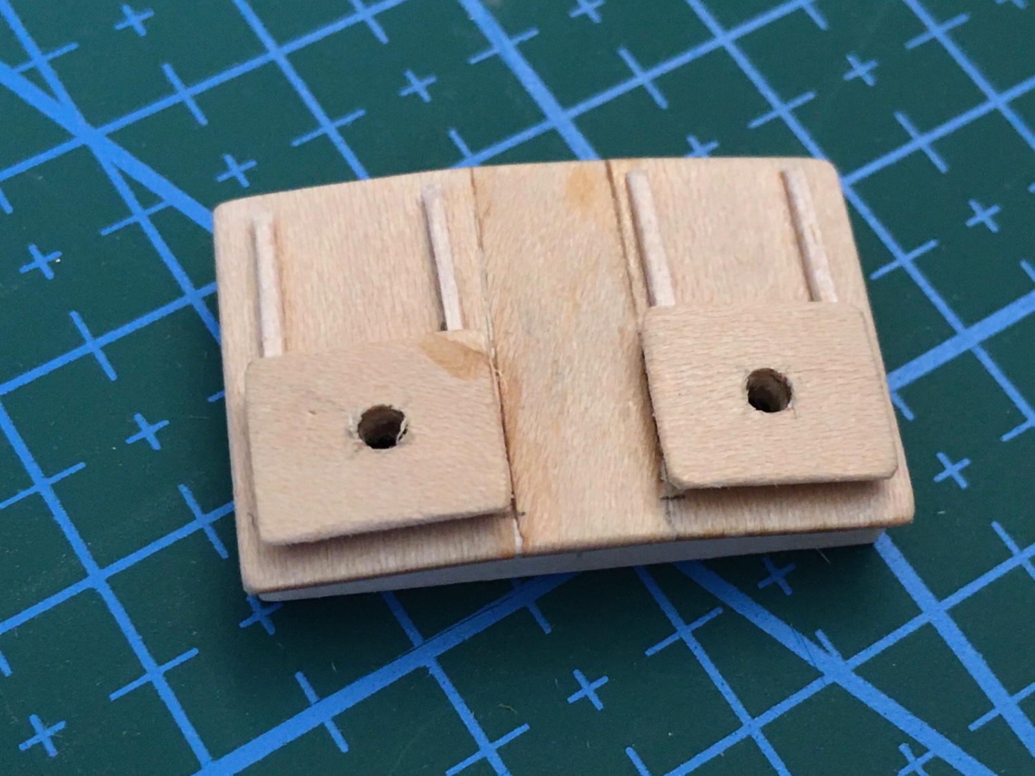
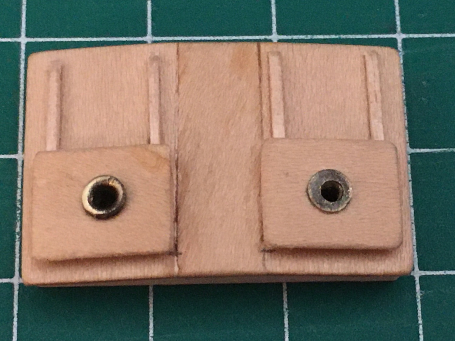
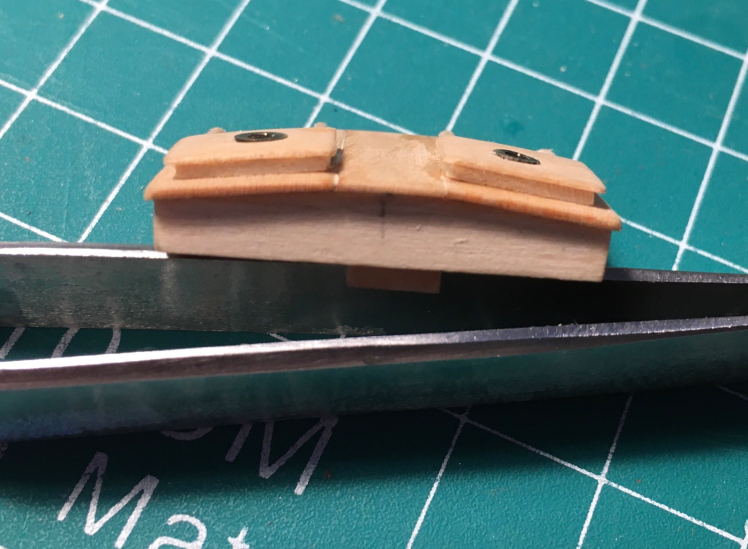
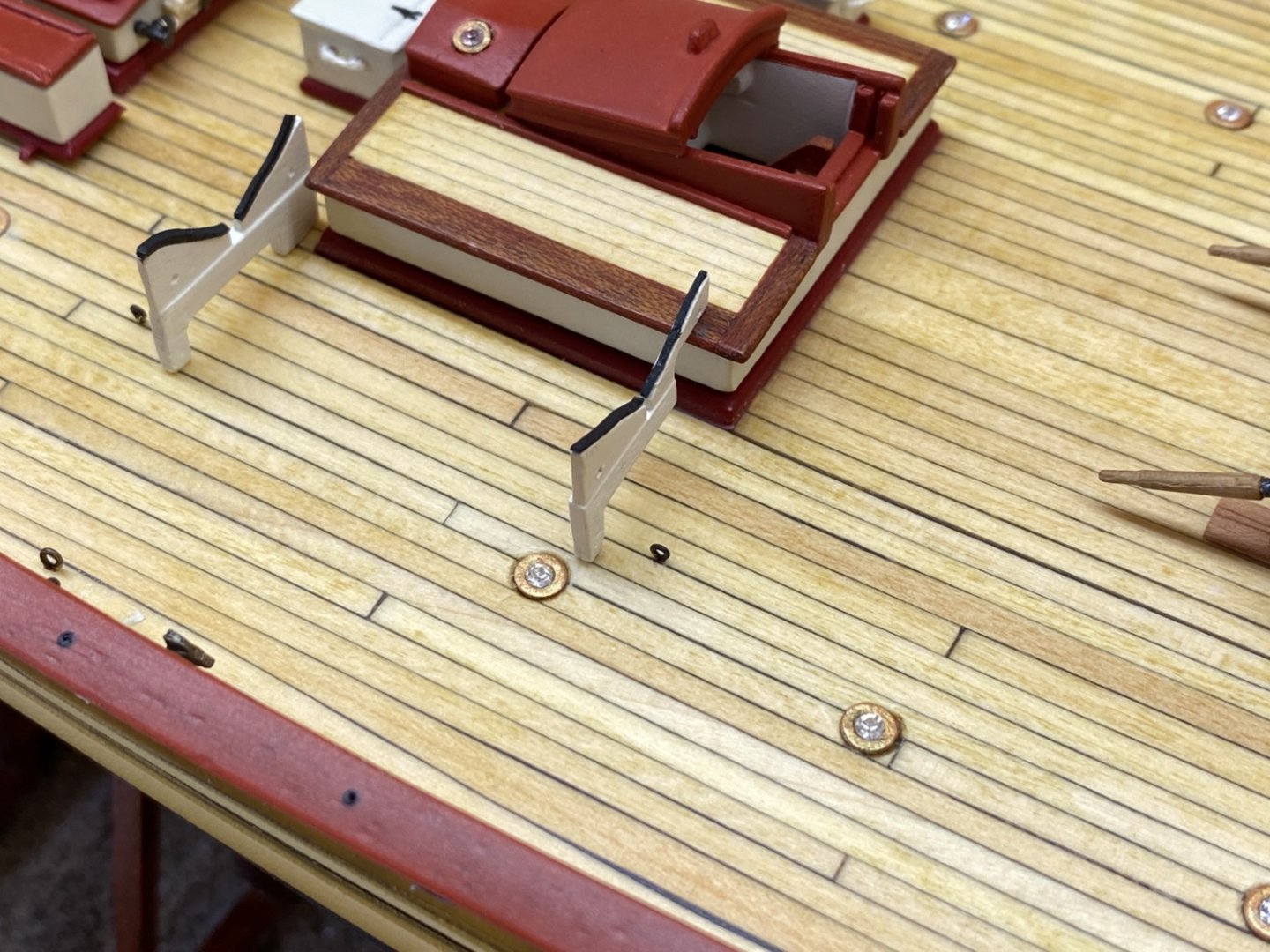
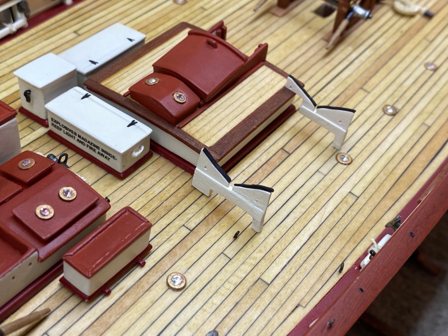
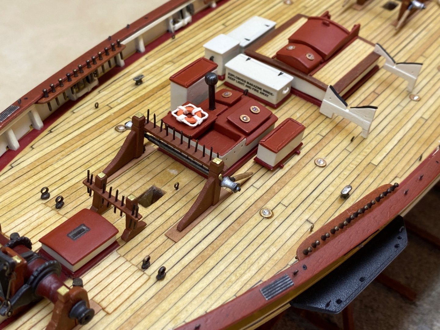
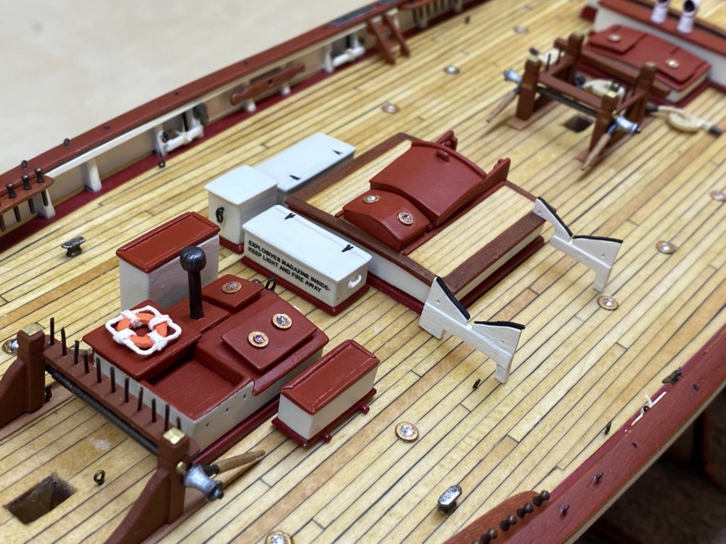
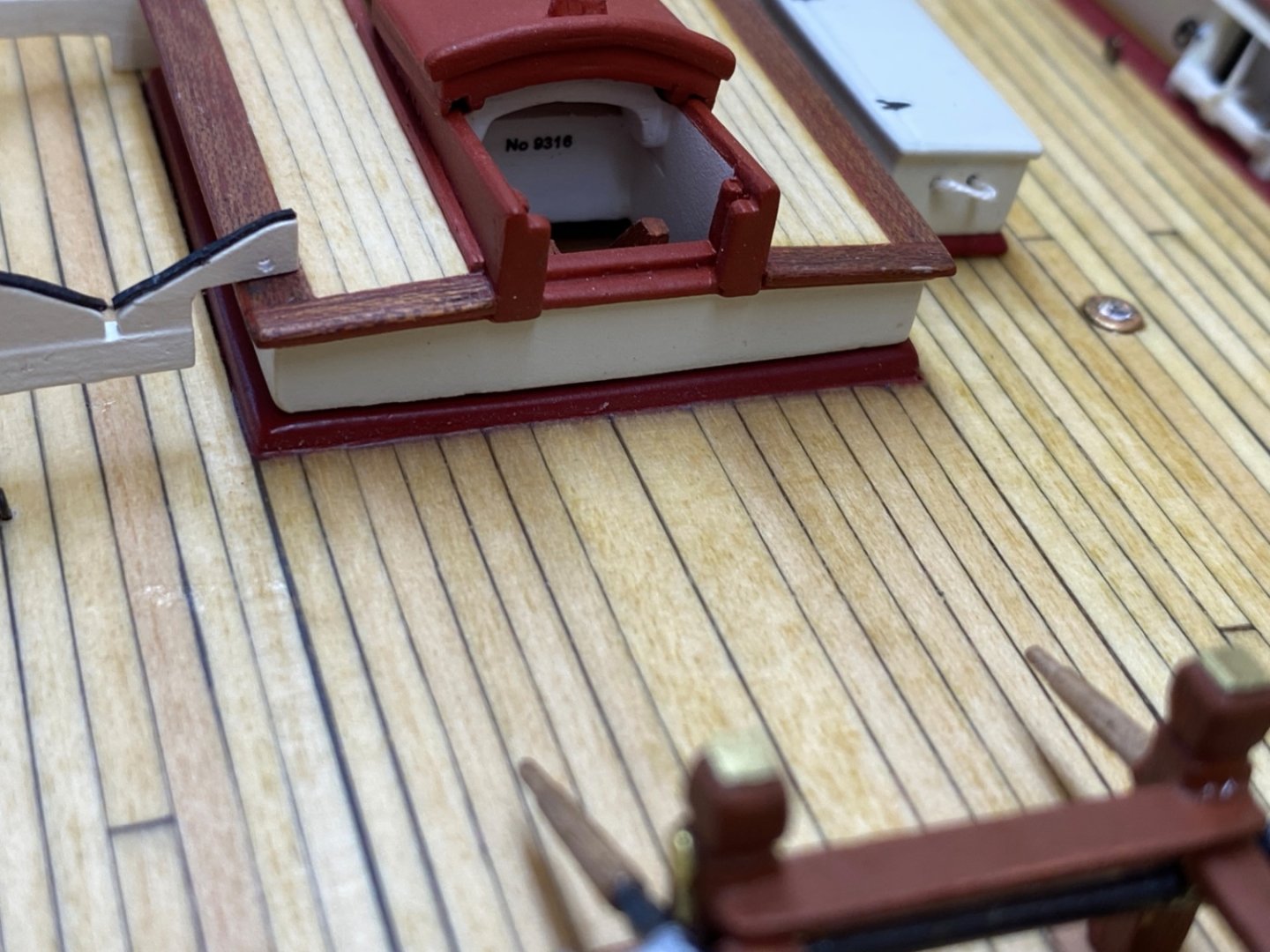
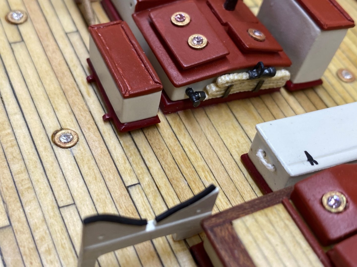
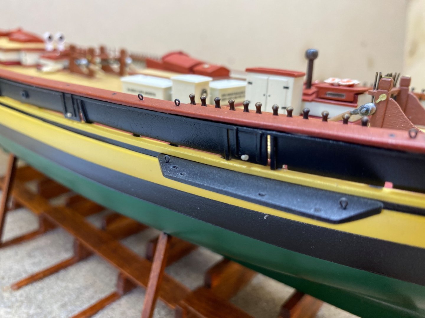
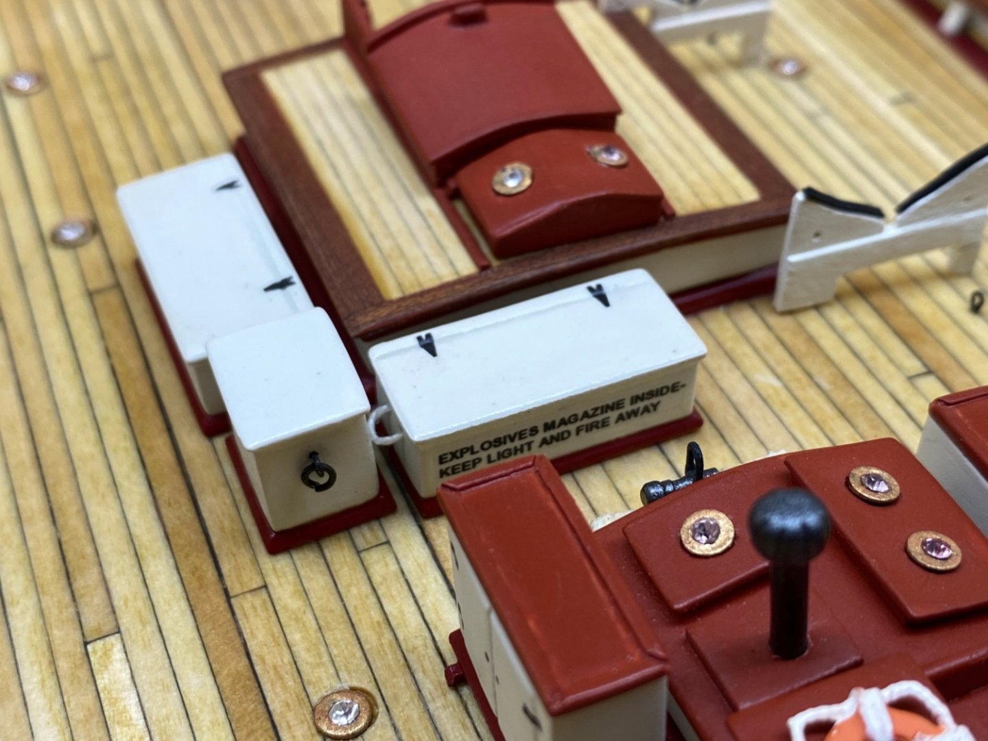
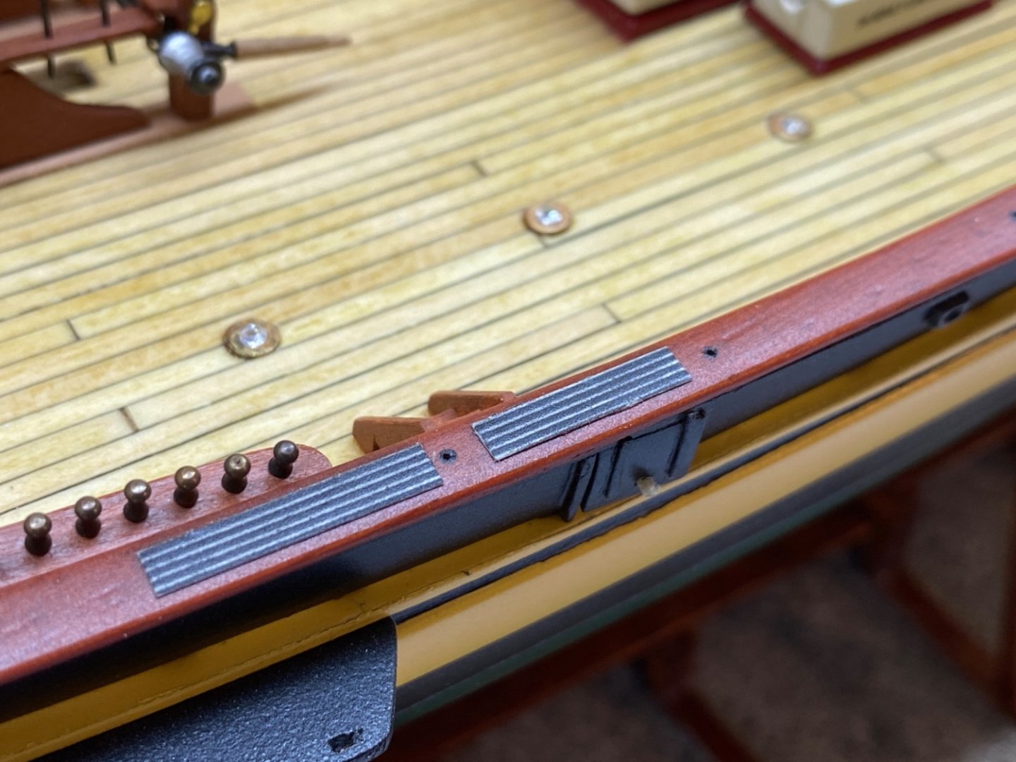
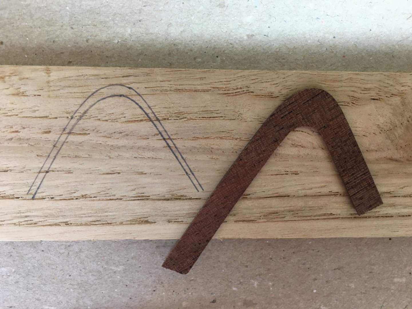
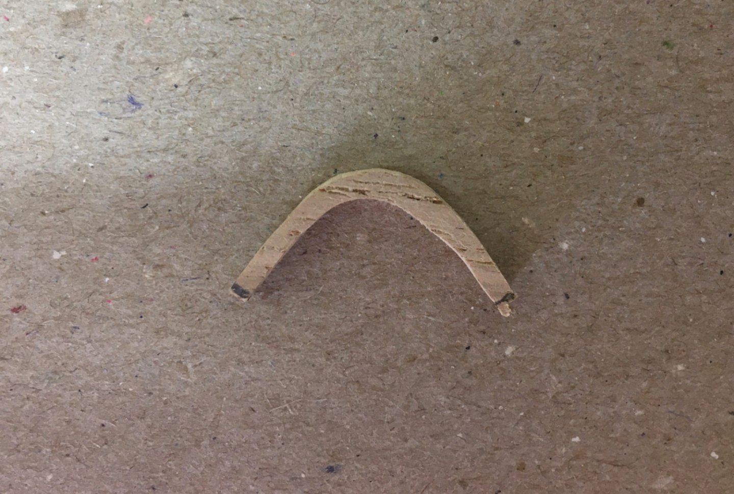
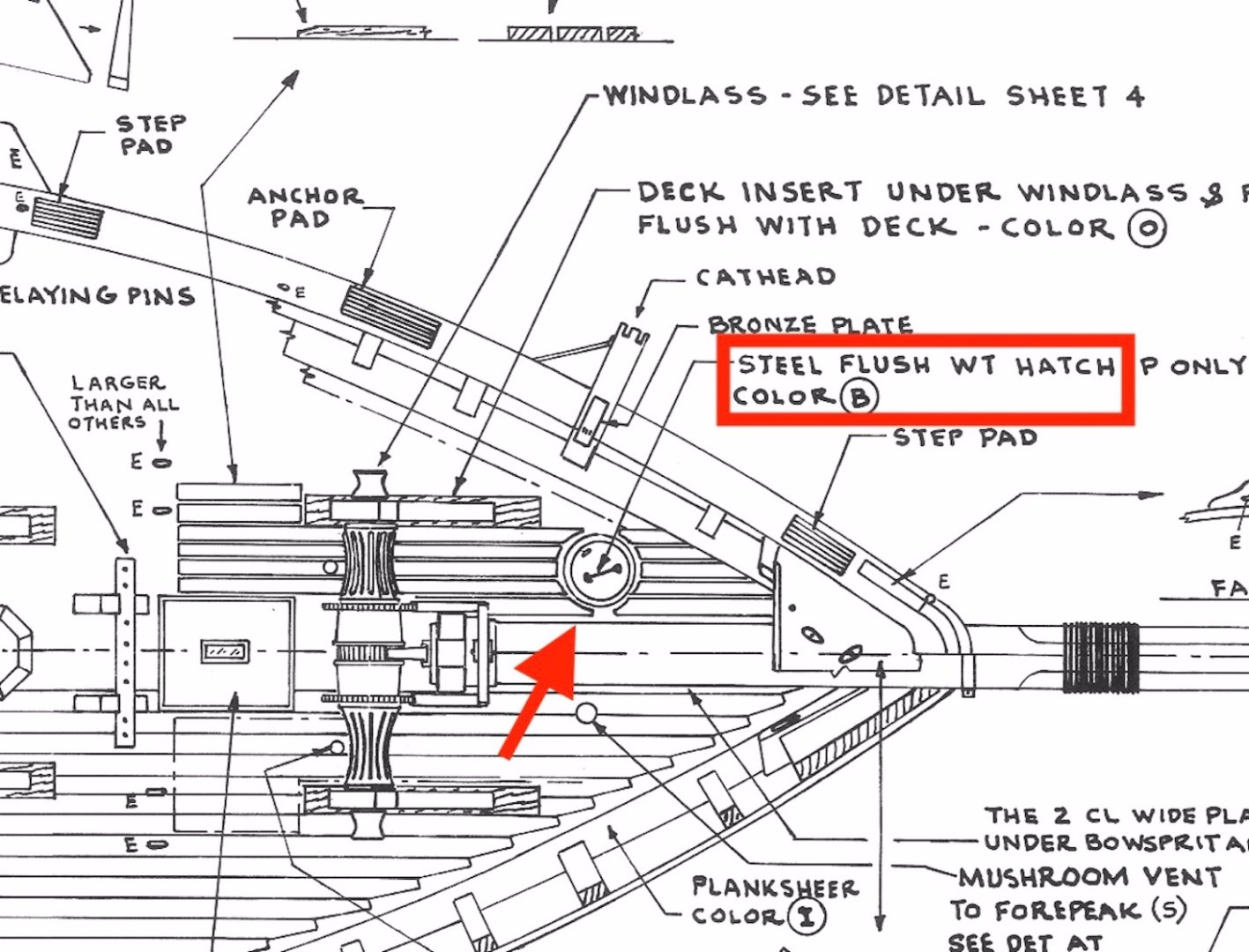
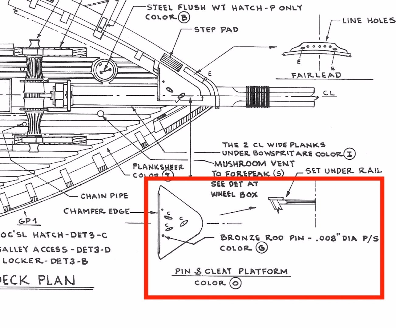
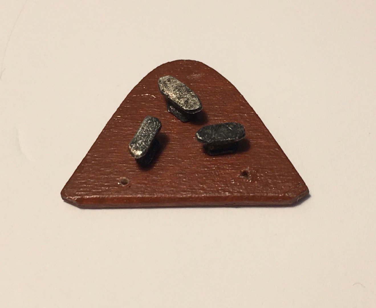
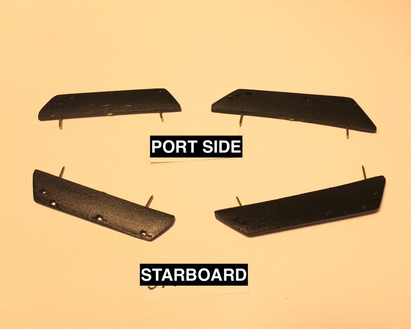
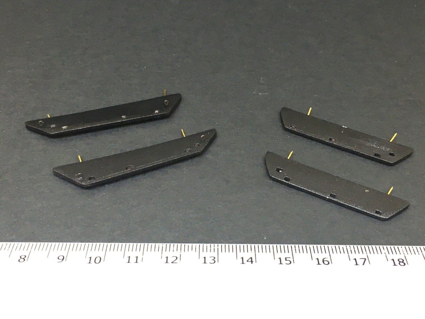
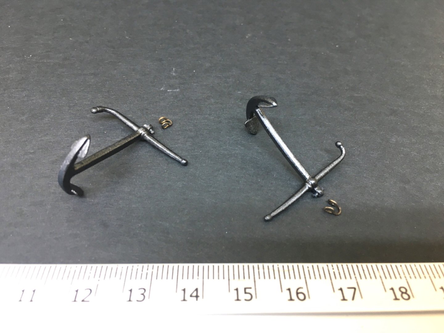
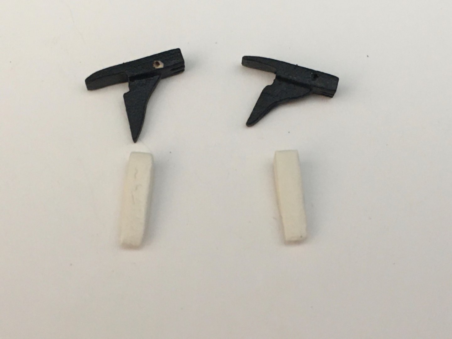
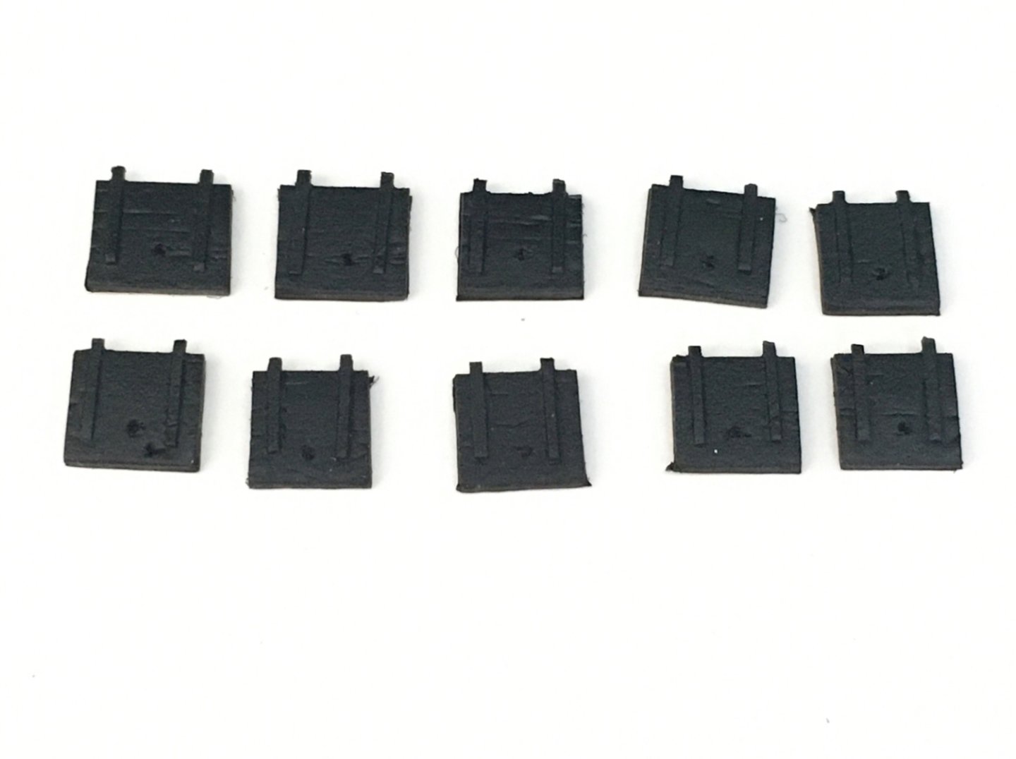
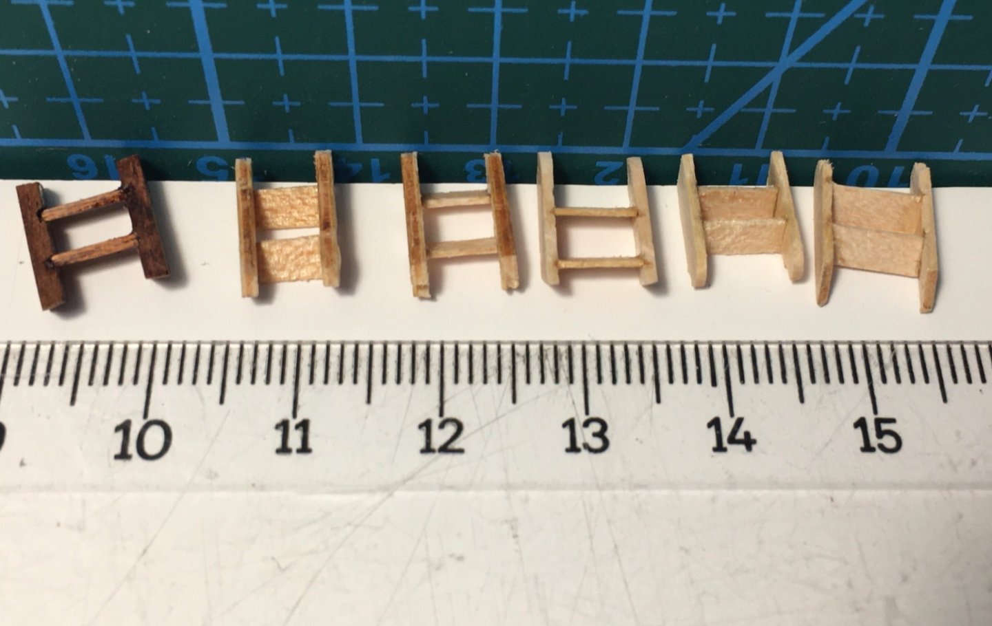
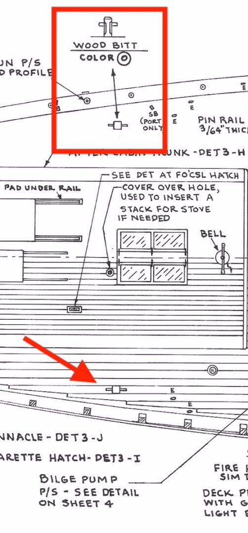
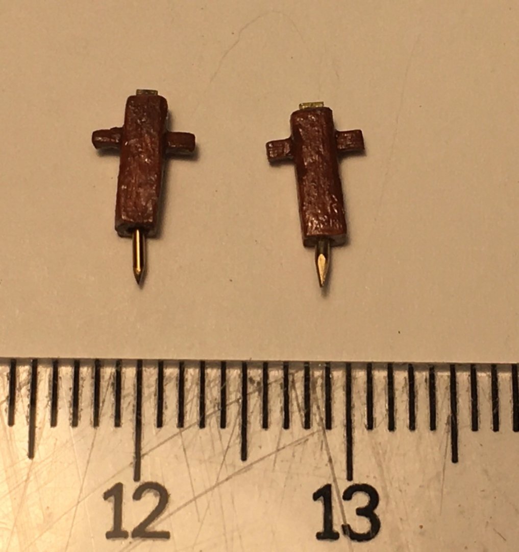
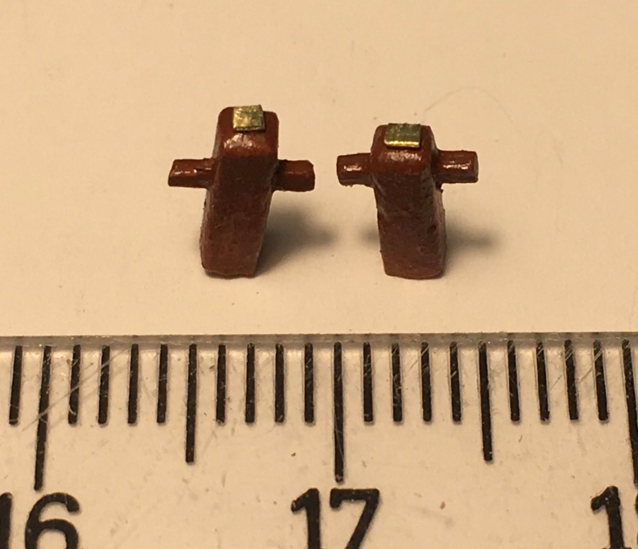
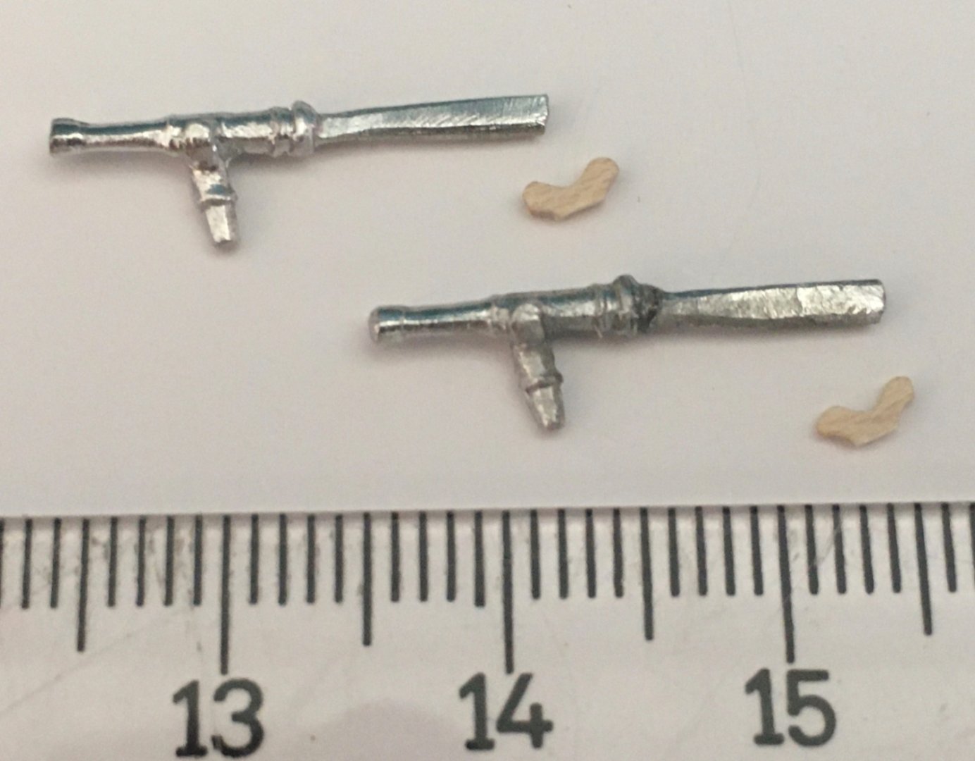
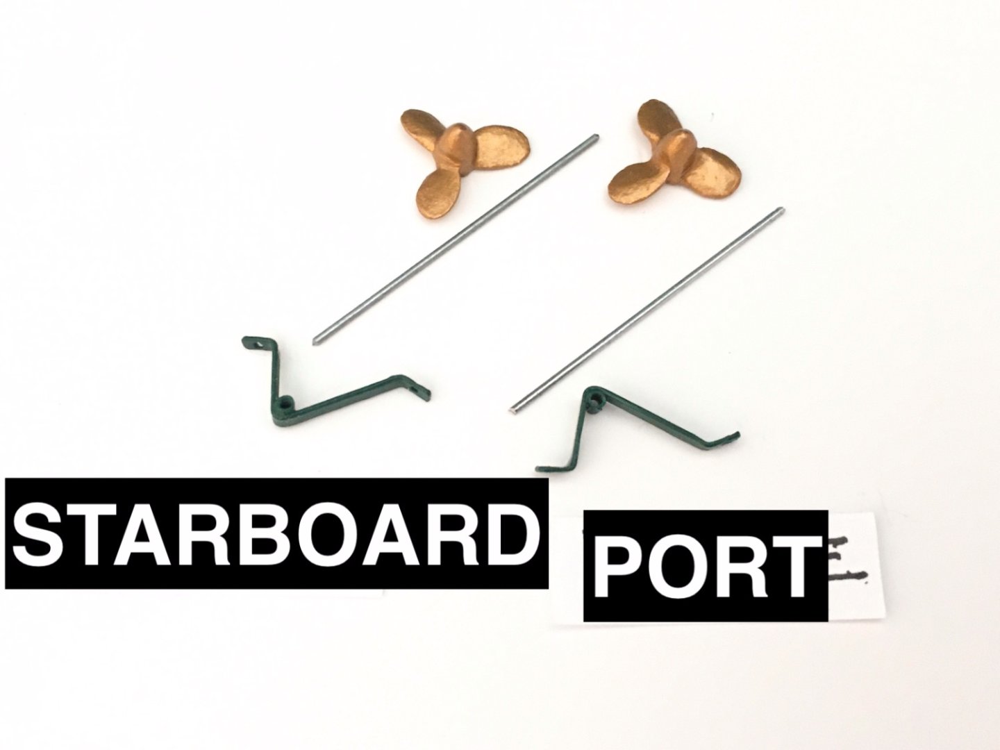
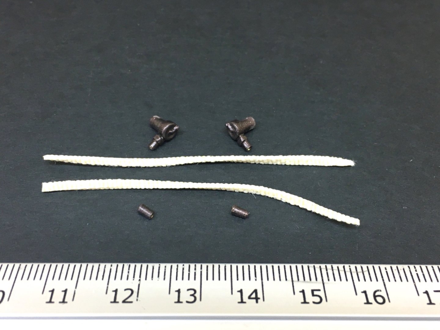
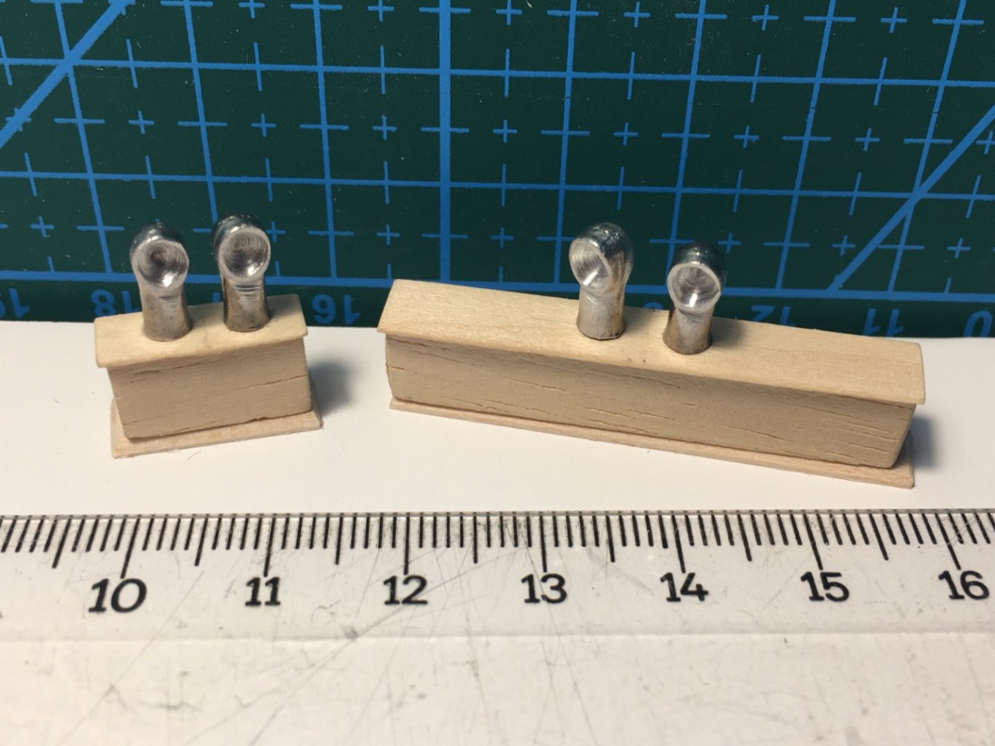
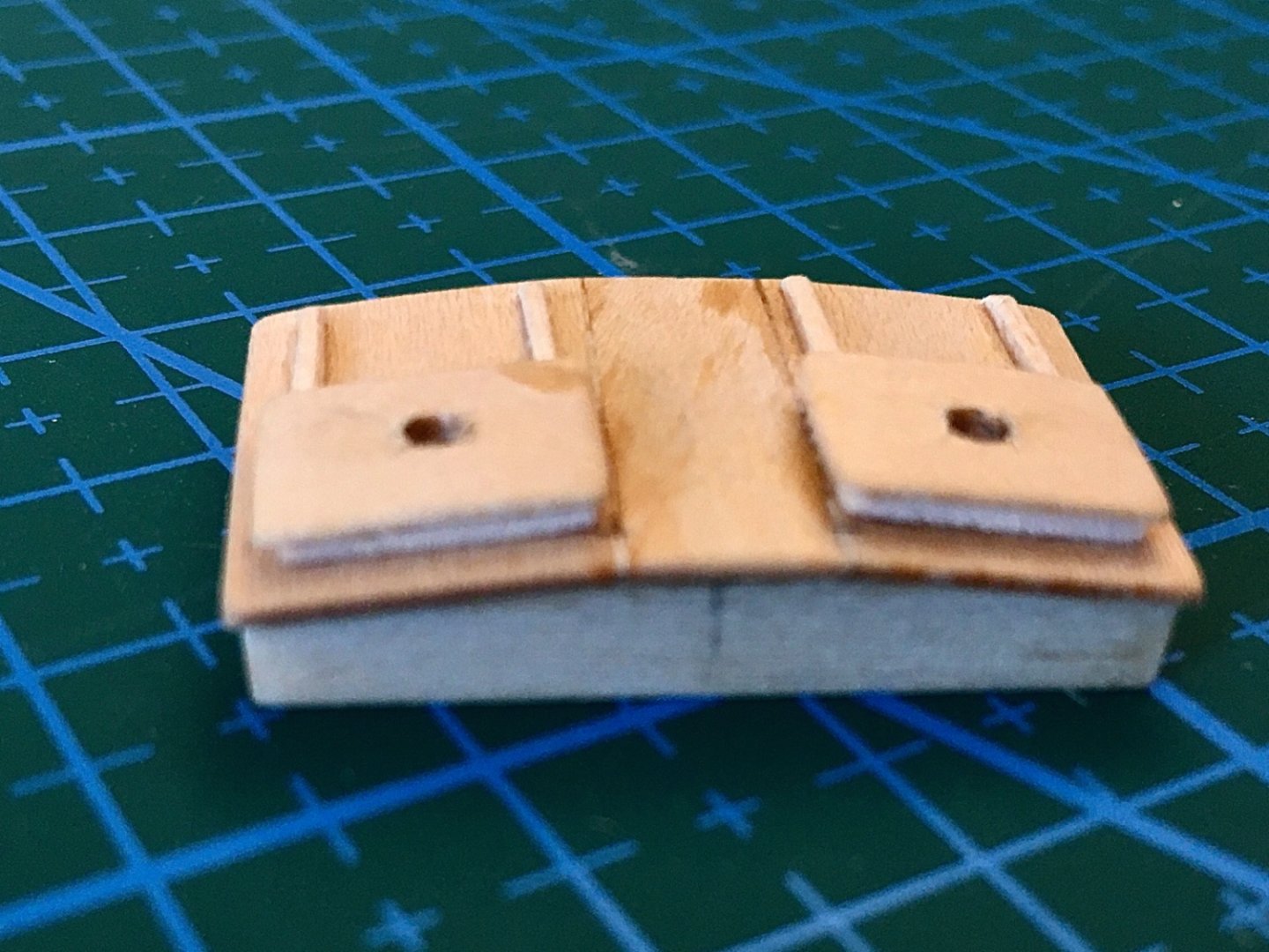
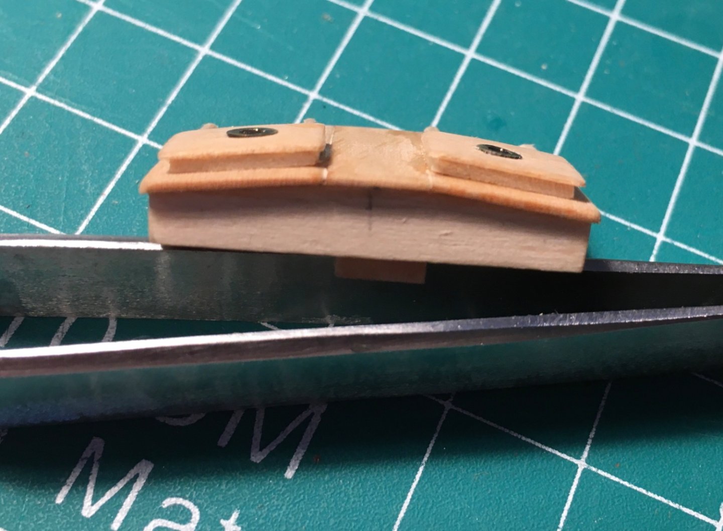
In this post there will be photos about the other structures of the deck. However the detail about the ship's boat and cannons will be in other future posts. The holes for eyebolts, life line stachions and belaying pin on the main rails were drilled also at this stage. At bow on the connection site of the port and starboard main rails, there is a structure called 'Fairlead' which has 5 holes for guiding the lines coming from bowsprit region. The piece was manufactured from a wood block. The outline of the structure was drawn on the wood piece by the aid of a jig prepared with reference to the main rail bow piece. The piece was cut by Proxxon scroll saw initially and sanded to final shape by using several sanding pieces. I had to prepare a second one because the first one did not align with the main rail surface at the bow. There is a steel hatch at fore deck on the port side of the bowsprit inboard part. It was prepared from Britannia casting block from a previous project. A small casting was hammered on steel surface and a circular (almost) piece was prepared. Then another piece with a little bit large in diameter and thickness is also prepared. These were glued together somewhat resembling a hatch cap. Two holes were drilled. A handle shape was prepared from suitable size brass rod and glued in those holes. Final color and dry fitting to the designated area. The triangular shaped pin and cleat platform at bow is prepared. Channels for chain plates on both sides of the deck were prepared. Two pins on each channel was inserted for extra support for the final installment of them to the hull. The eyebolts were placed and the holes for chain plates were opened. The anchors and ( chain and rope) shackles were prepared and painted. Catheads were prepared and painted. Gunport lids were prepared. Each one differed in size as the measurements of the gunport spaces differ. I did not like the first batch and prepared another set. One of the metal bars (brass strips) was kept long until the final point, to ease when holding the part during painting stages. Before the final installment the bar was cut to size. First batch ! New and first batch together. (Numbers indicate the gunports. 1 at bow and 5 at aft. S is starboard , i is port. Initials for turkish names sorry!) The two steps at port and starboard sides occupied a lot of time. After many trial and errors I used the step sides from a previous project and was able to manufacture two acceptable ones. I planned to use some of the other ones as the steps in after cabin and main salon. There are two wood bitts near the aft deck. These were prepared and , like the previous ones, nails were placed at their bottom side to support when gluing them to deck. Swivel guns were prepared with their support pieces to be placed on main rail. However at the final installment stage the support pieces were broken and new ones was not replaced. Propellers were painted brass color. Shafts were cut to size from steel rods. Bilge pumps, hoses and nozzles Some of the other structures Wood bars on the inboard sides of the gunport spaces were also prepared and painted at this stage. However I do not have any pictures of them before their final installment.


- 114 replies
-
- 6
-
-
- Pride of Baltimore II
- Model Shipways
- (and 1 more)
-
I like to inform the viewers that I made editions to posts # 36,52 and 54 and added some photos which you may find interesting.
-
Yves, Thanks a lot for your nice comment
-
Chris, Thanks a lot for your encouraging comment.
-
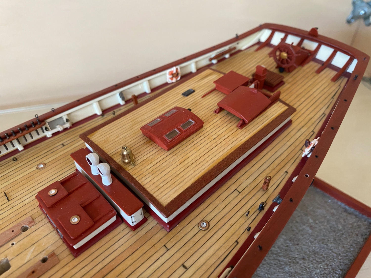
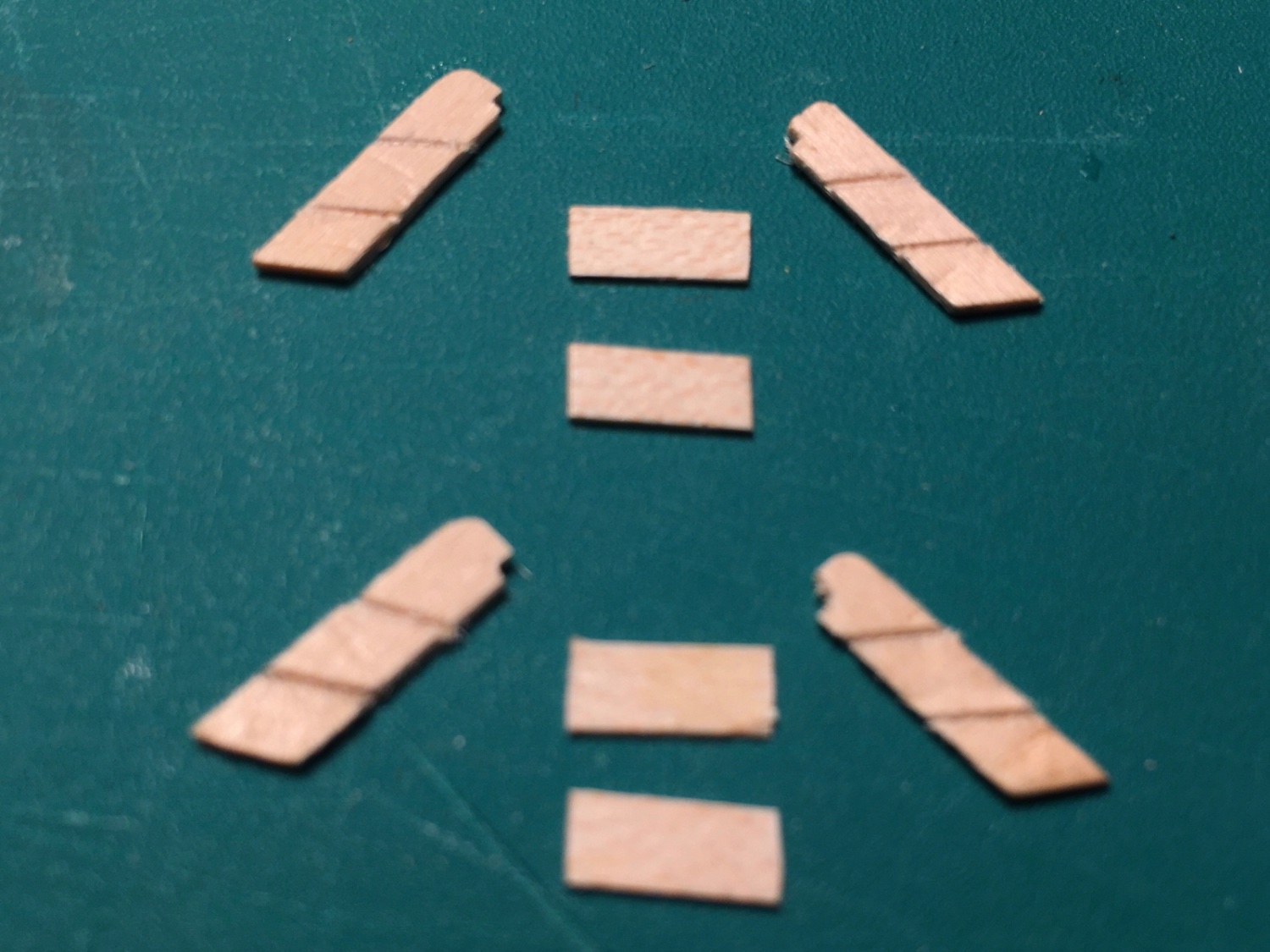
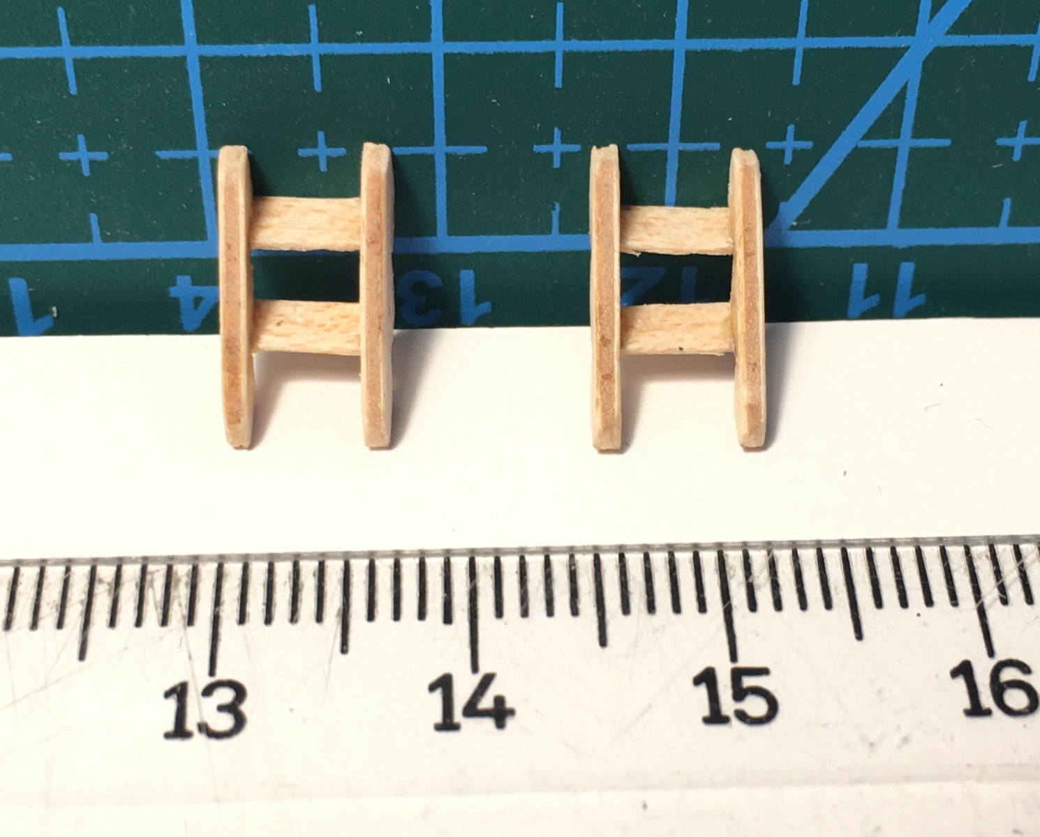
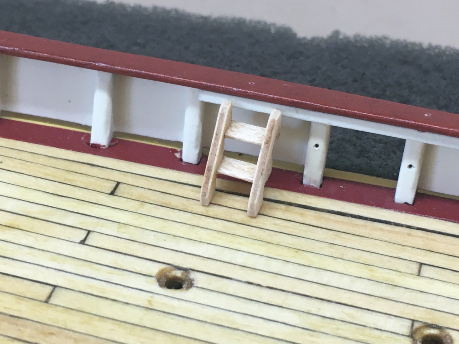
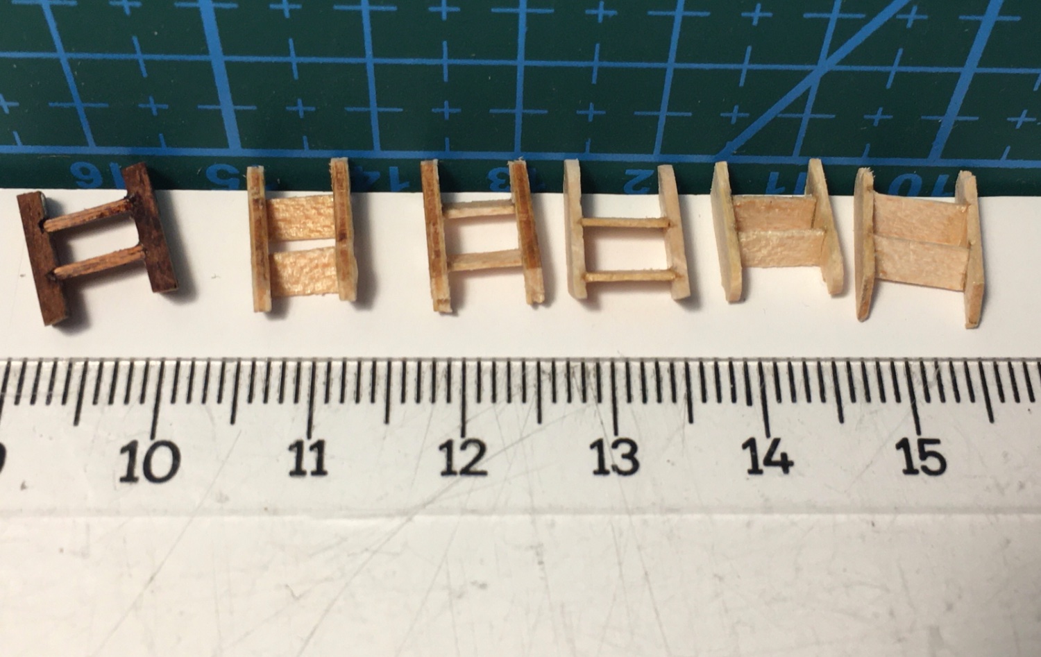
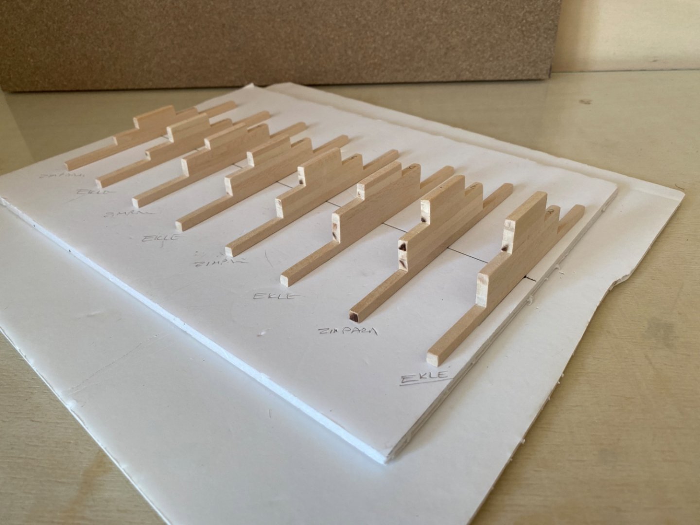
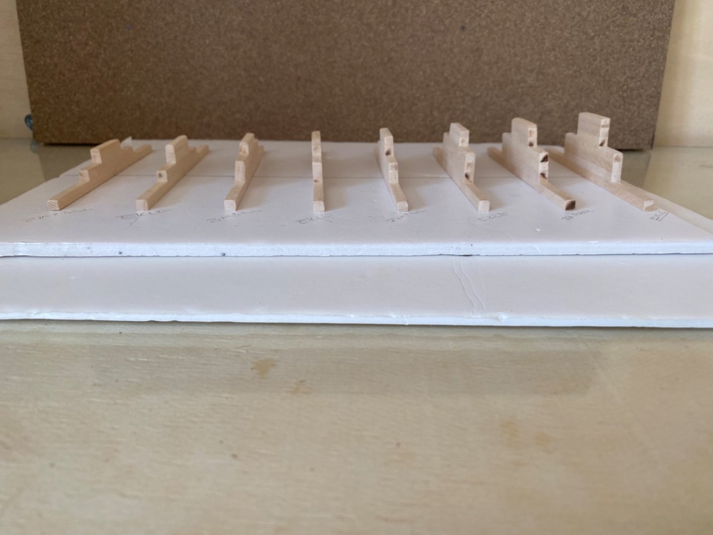
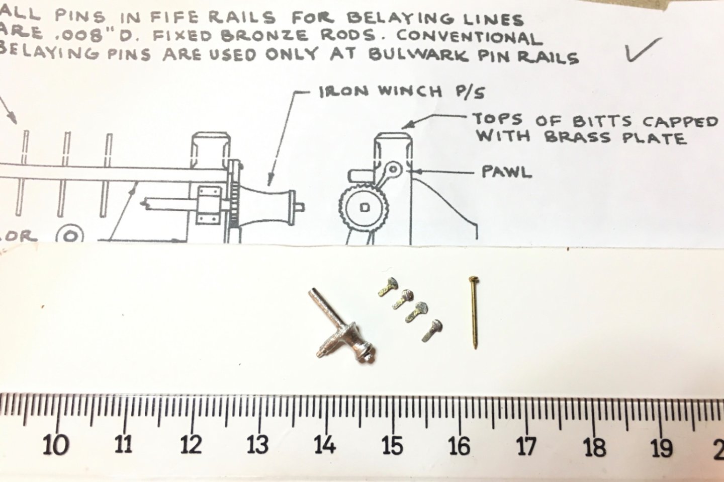
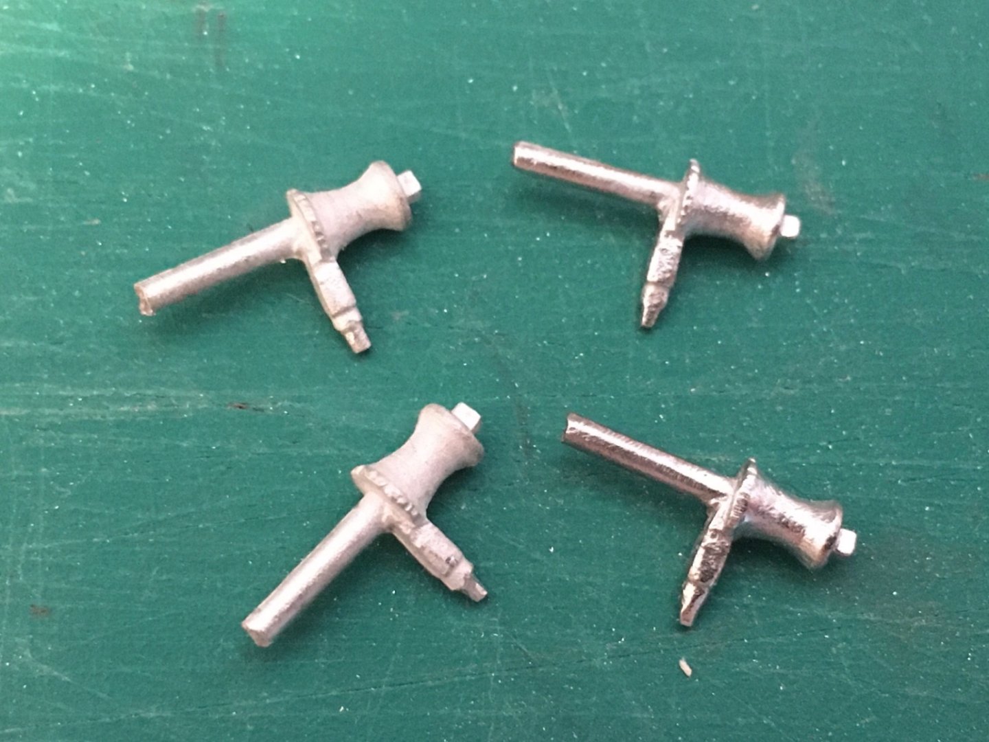
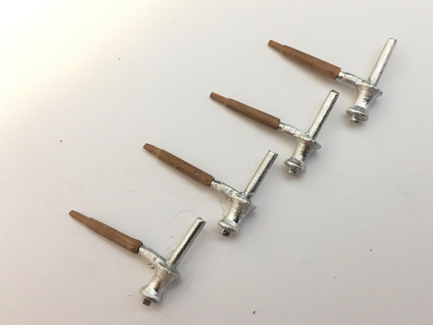
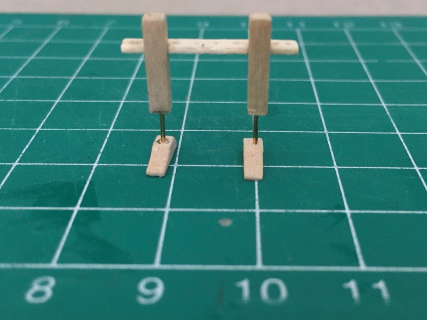
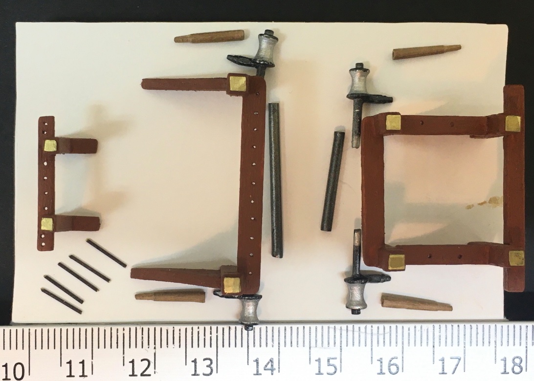
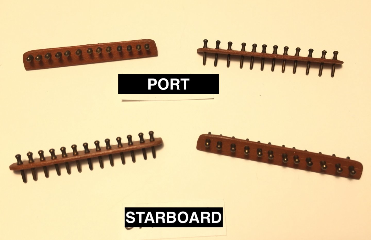
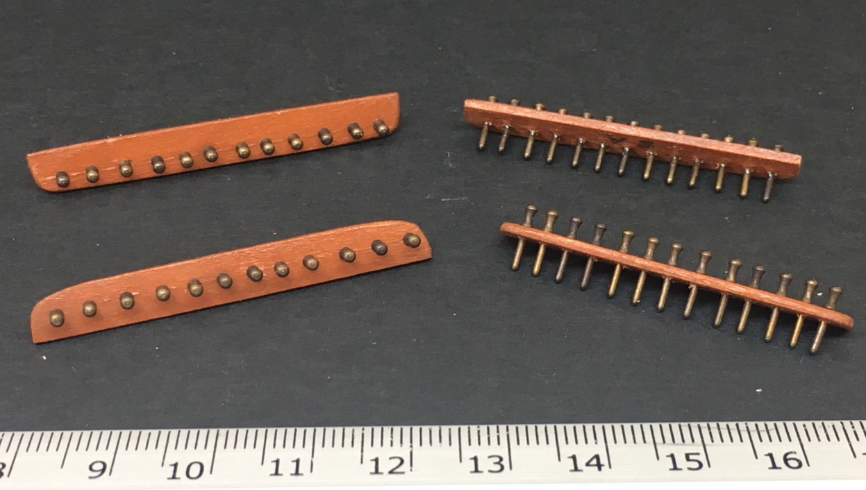
There are three fife rails . One at the bottom of main mast and two at the bottom of fore mast. The wood pieces are prepared. Holes for nails were drilled at the bottom of the corner pieces. Wood handles for the winches were prepared from mahogany dowels turned in my so-called Dremel lathe !. Winches Winch handles Fore mast fife rails Main mast fife rail Winch connecting rods and their placement The pieces were glued and temporarily placed on photo blocks After painting At this stage pin rails at bulwarks were prepared and painted. There are four pin rails two at each side.


- 114 replies
-
- 4
-
-
- Pride of Baltimore II
- Model Shipways
- (and 1 more)
-
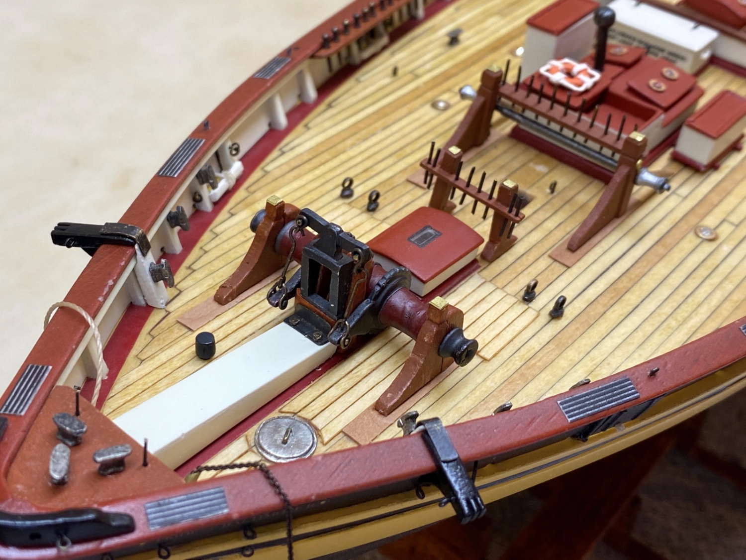
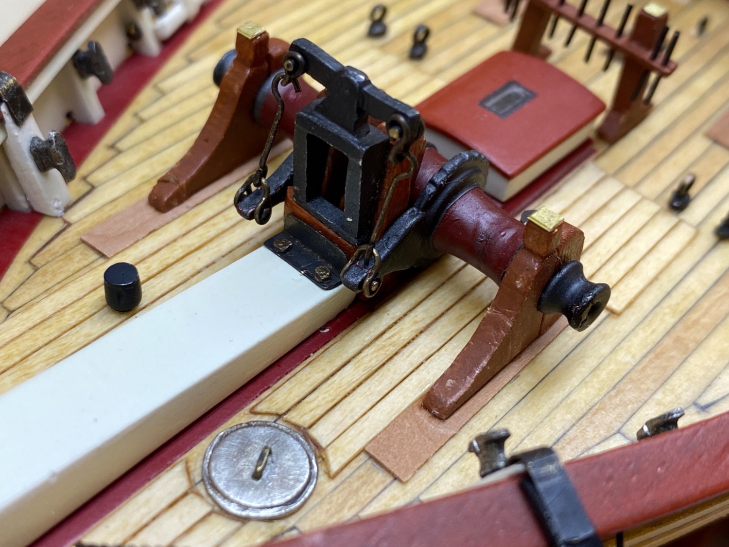
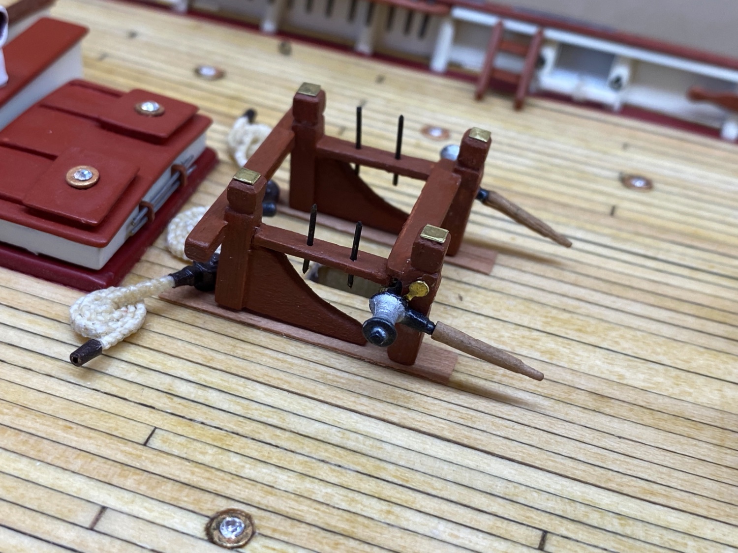
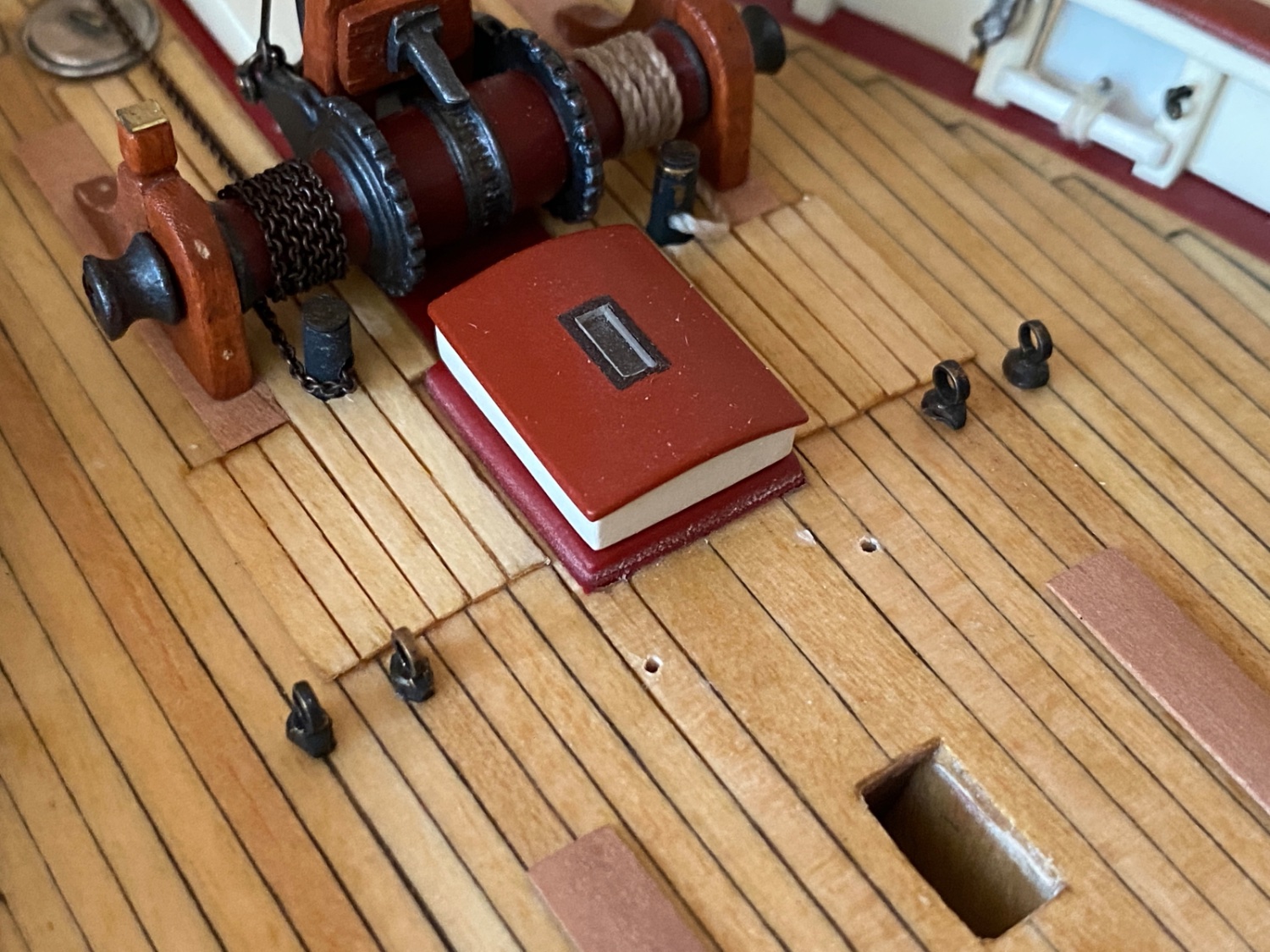
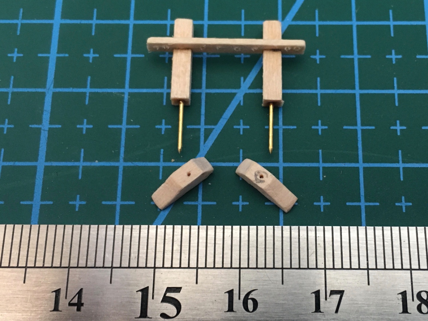
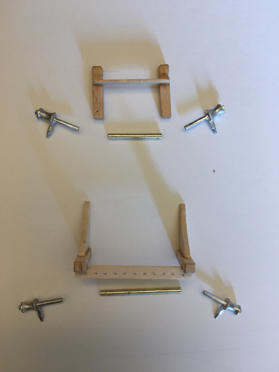
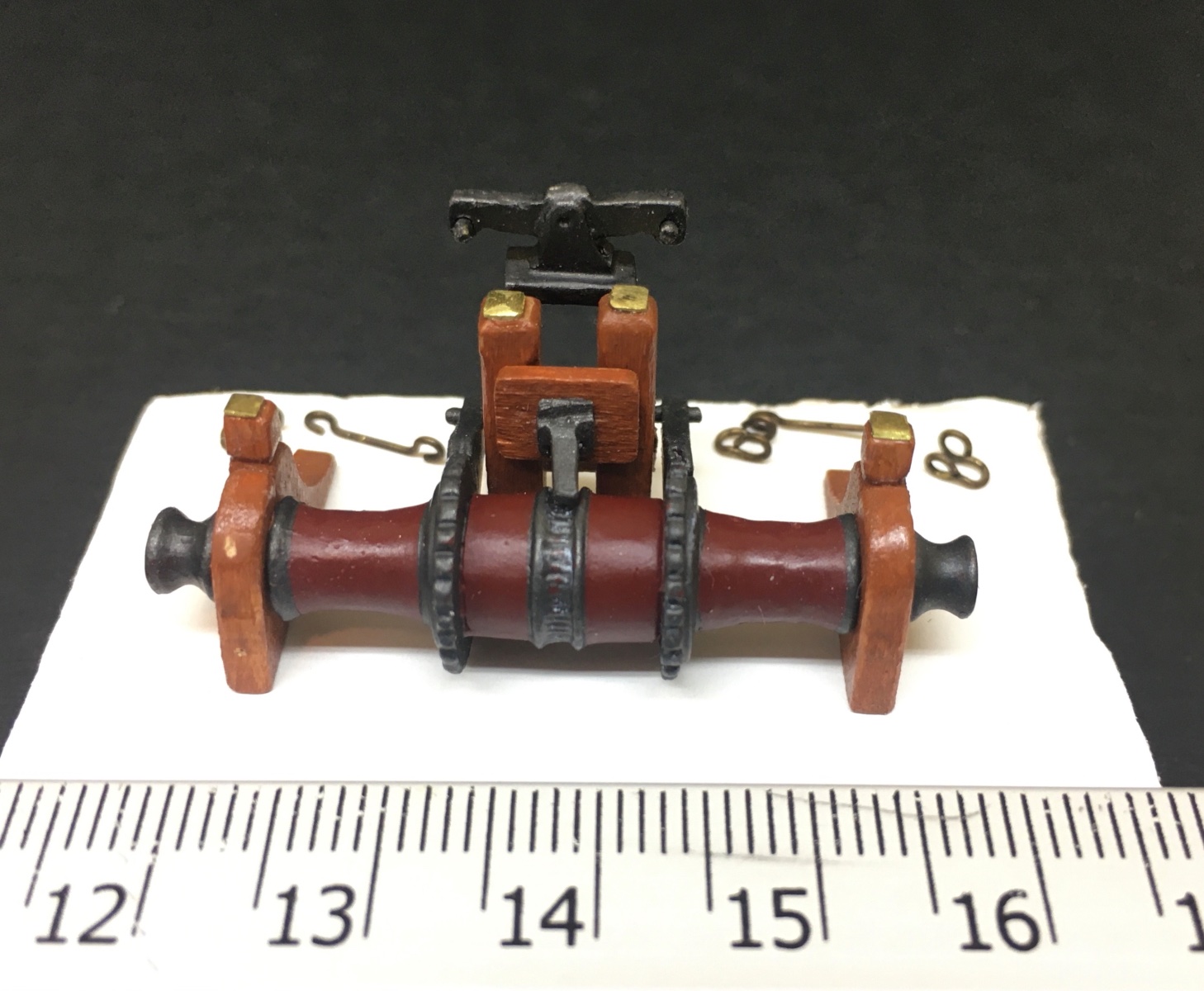
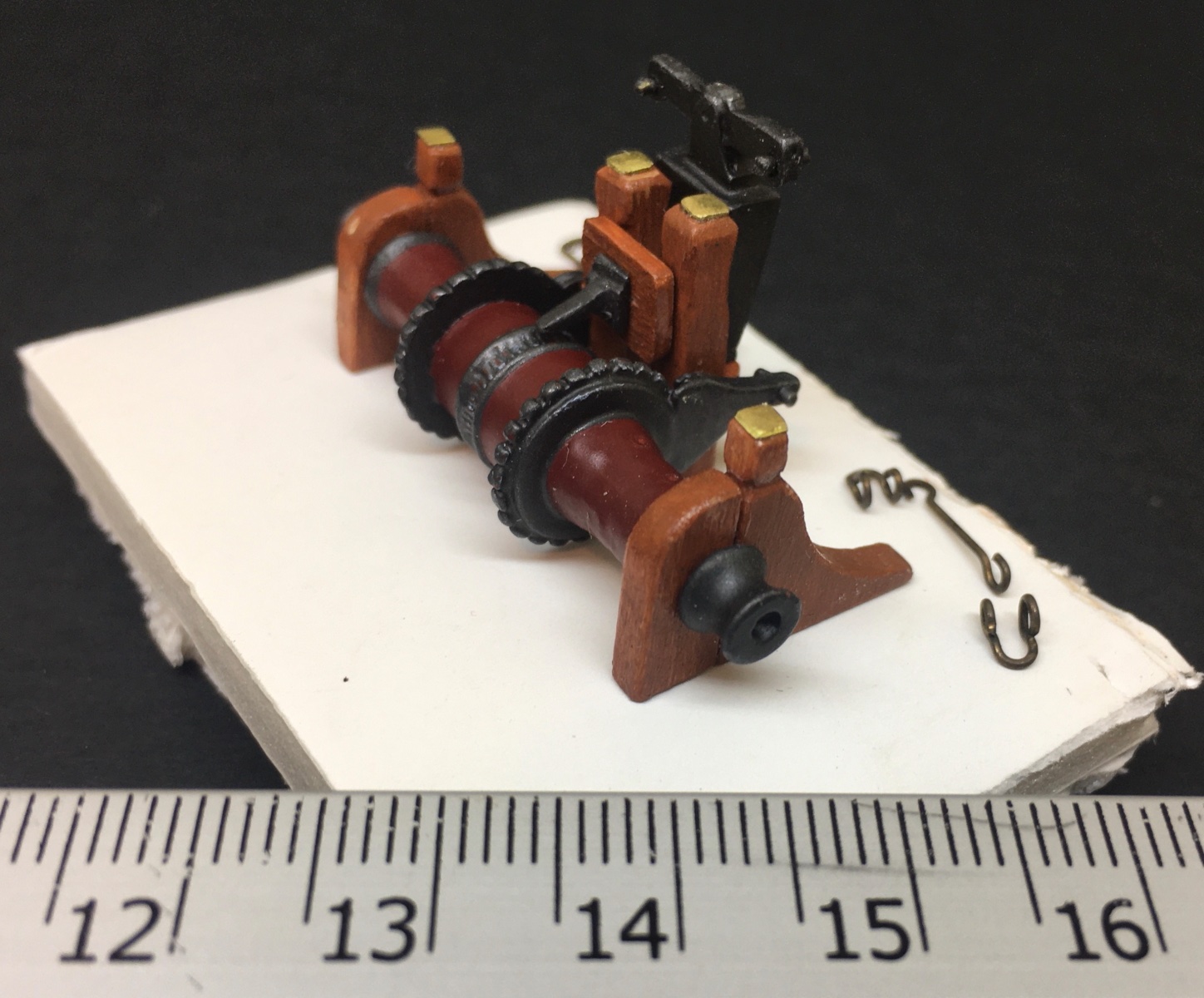
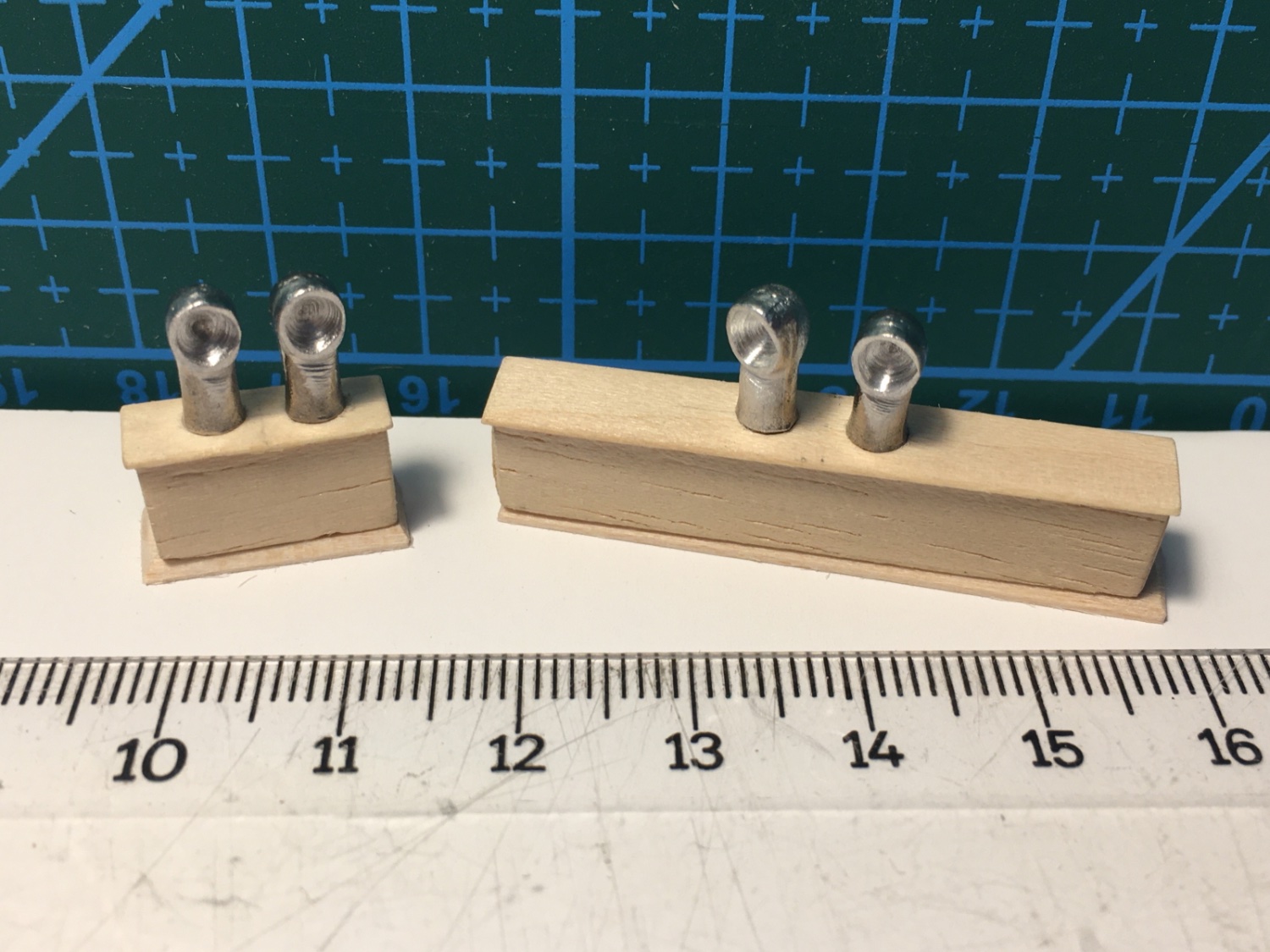
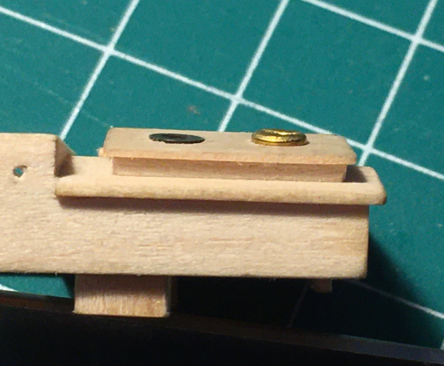
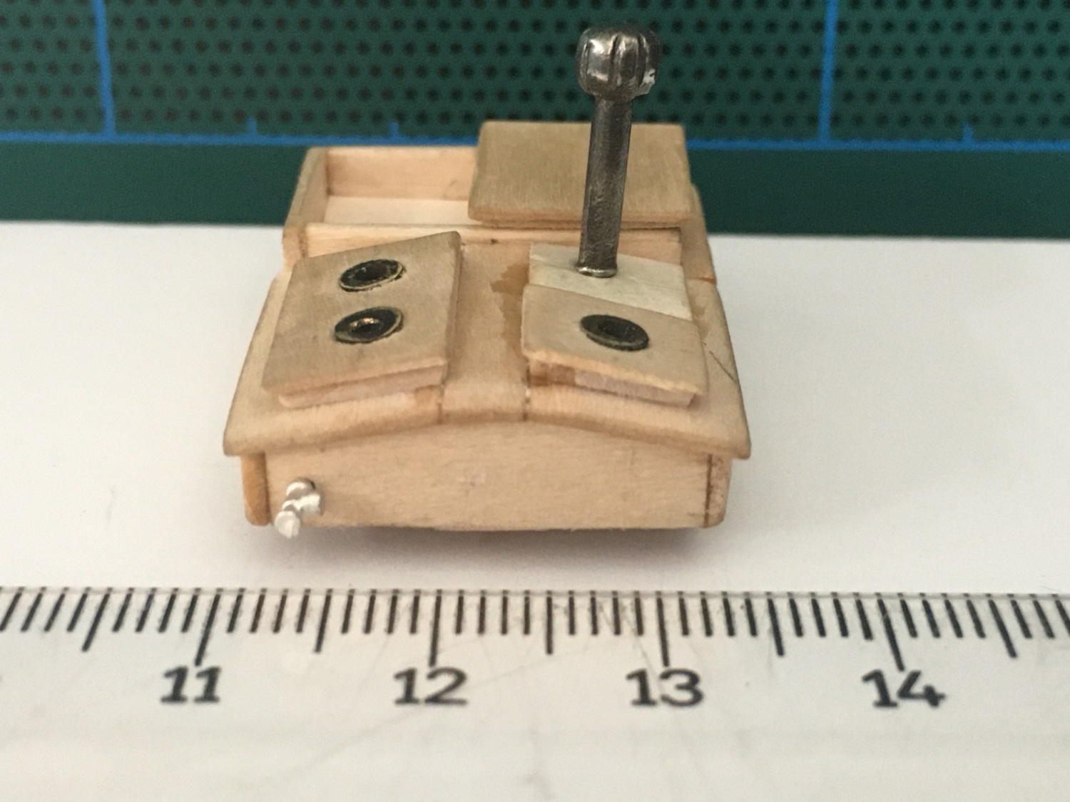
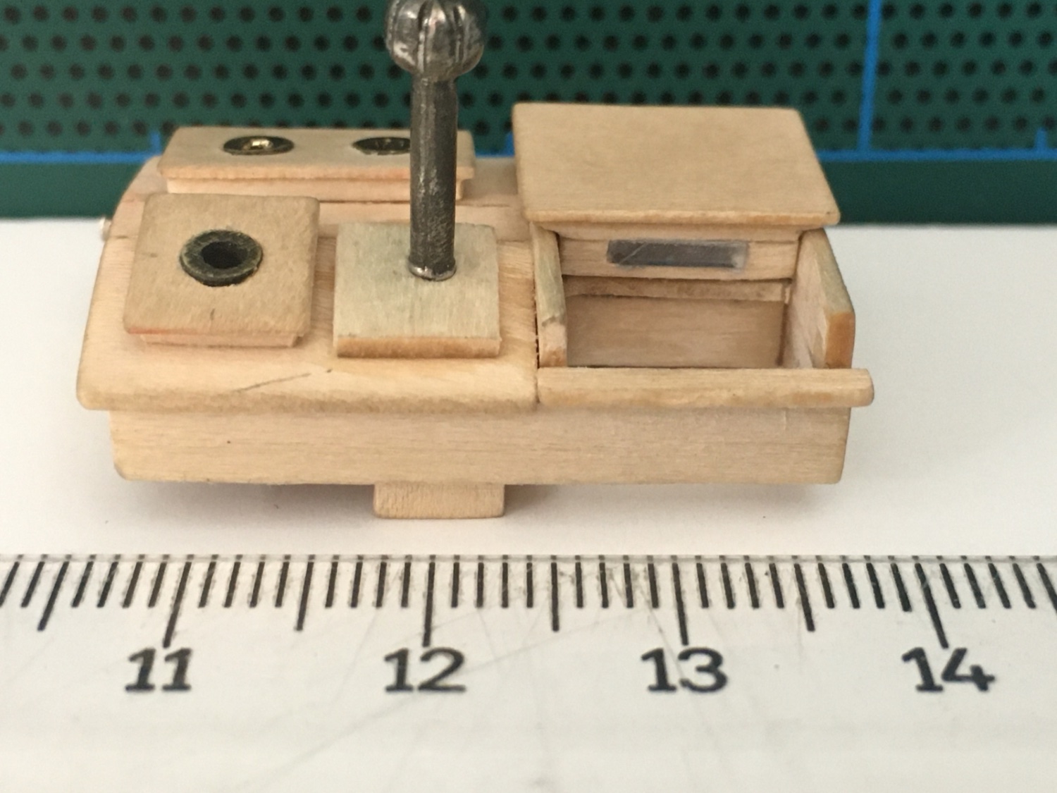
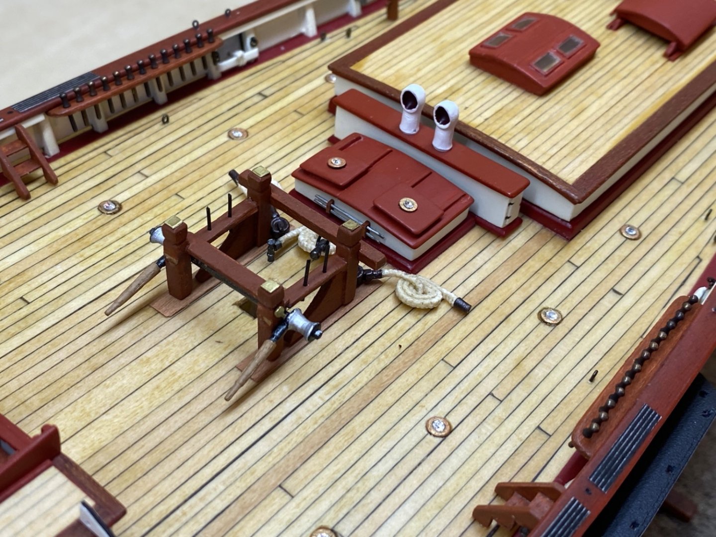
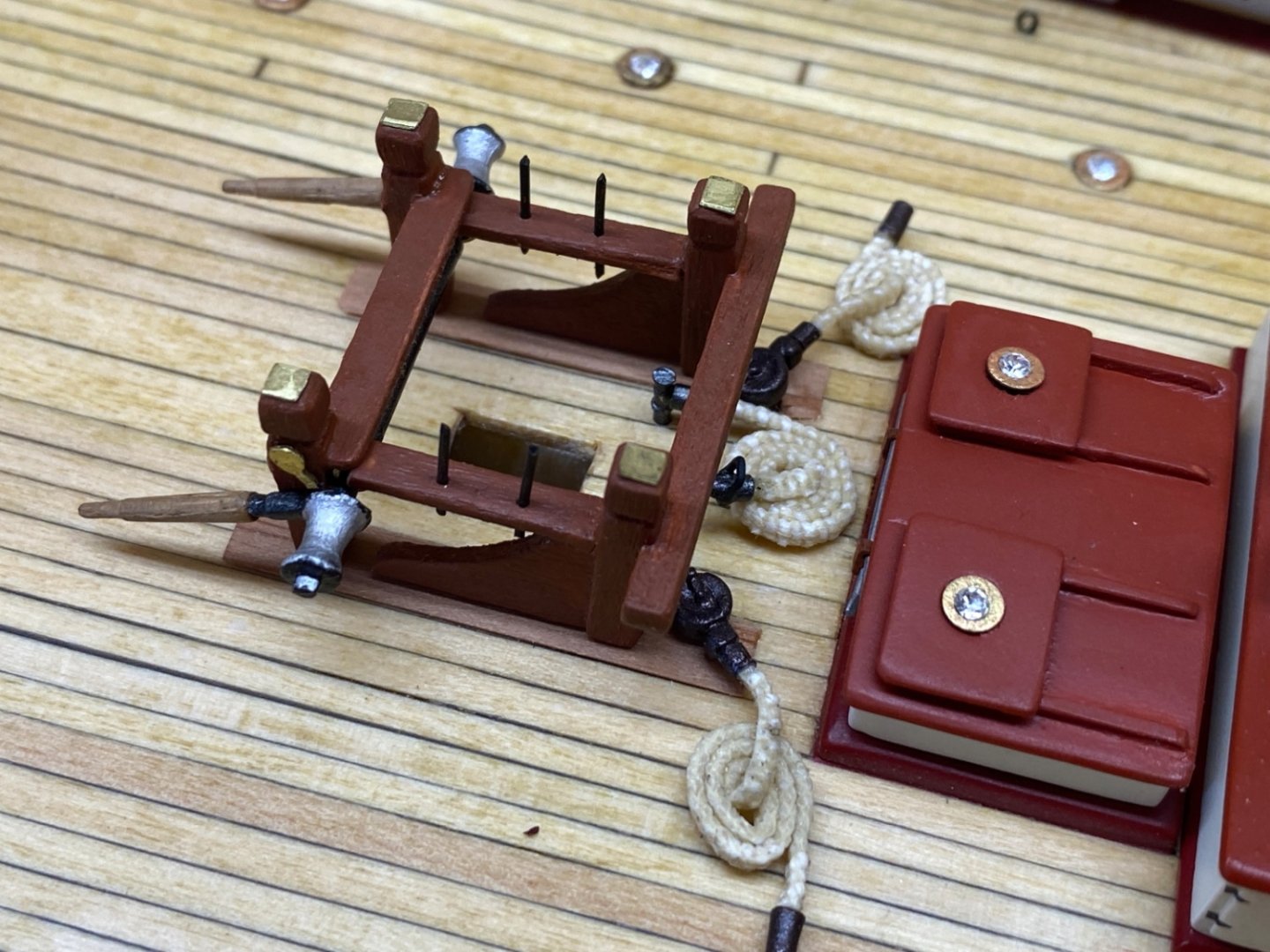
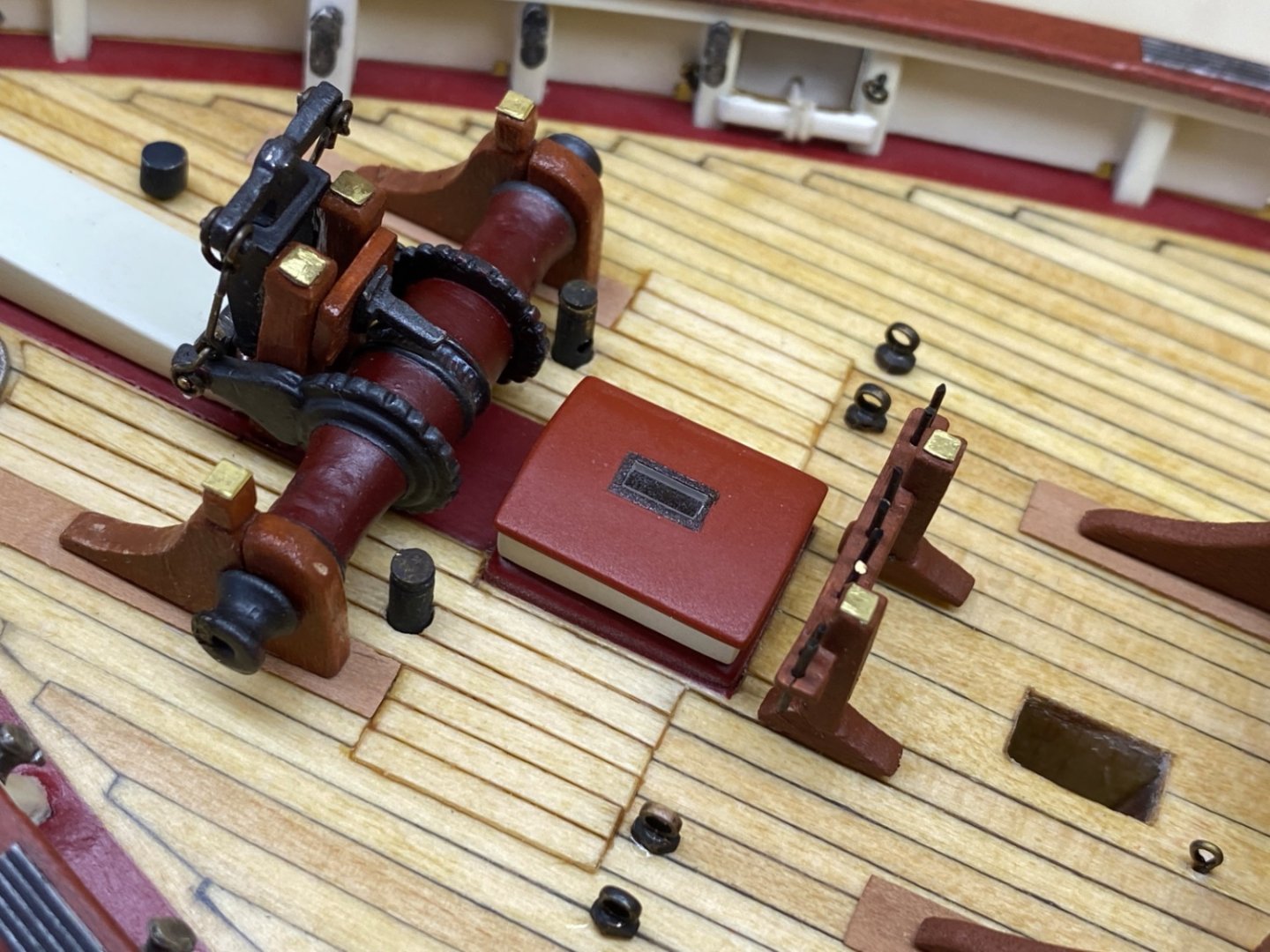
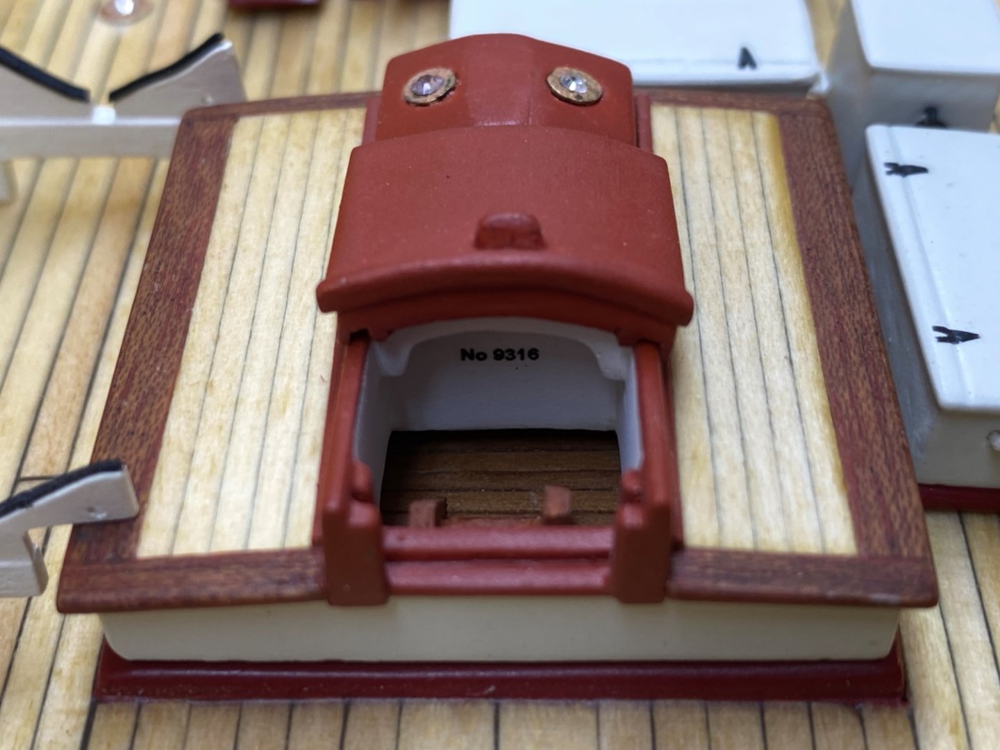
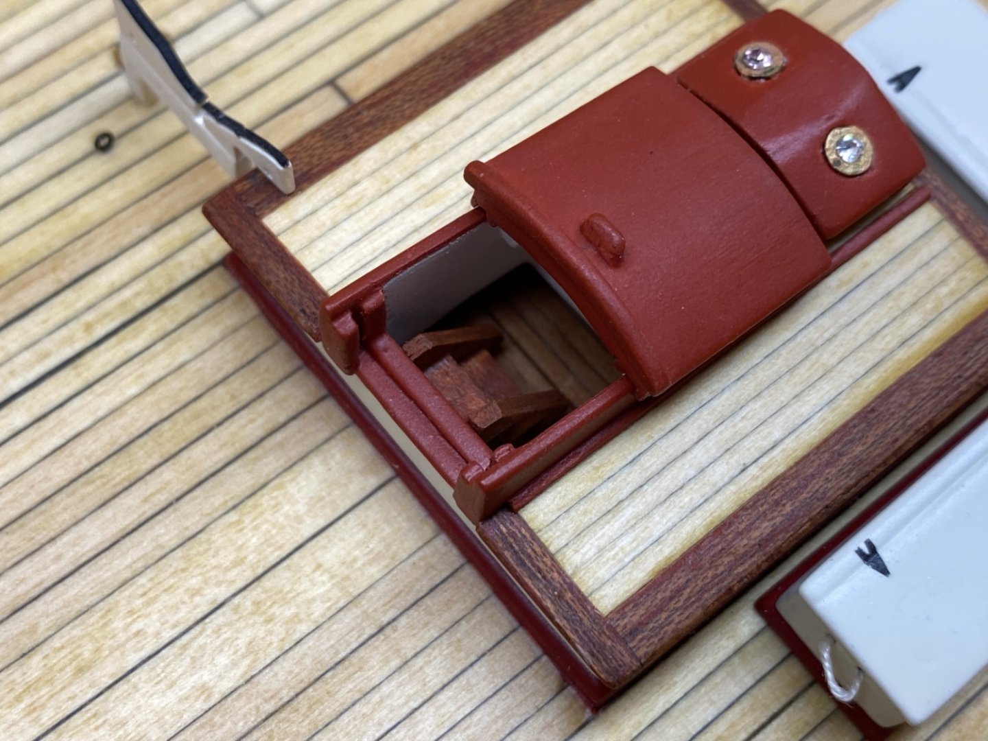
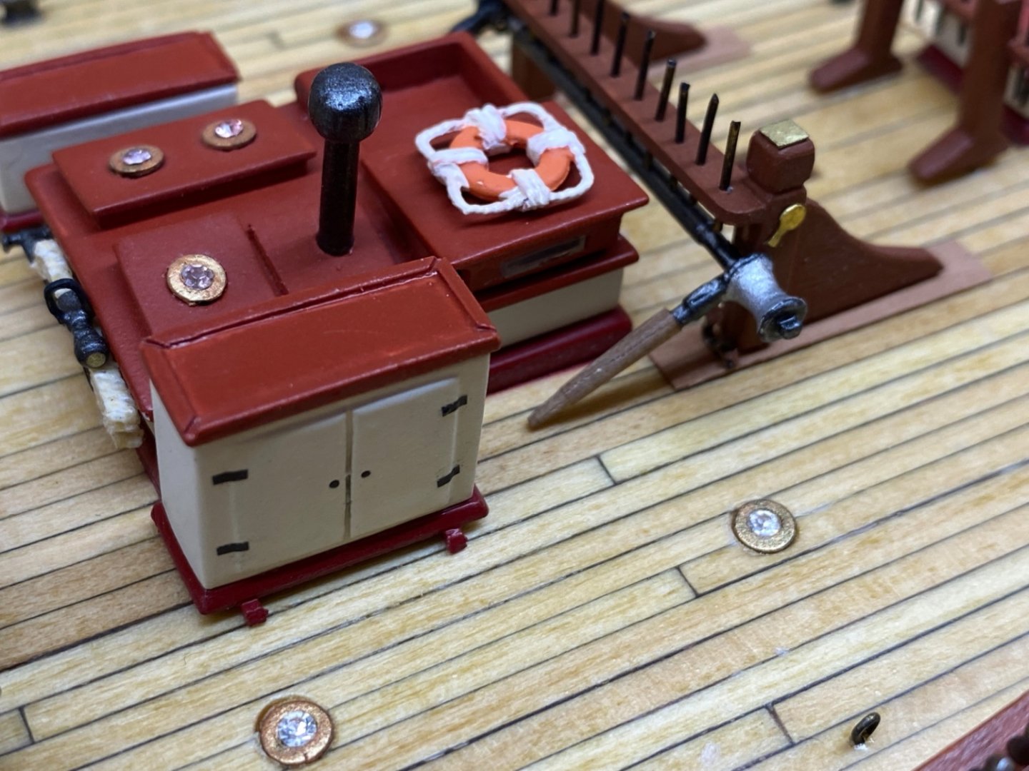
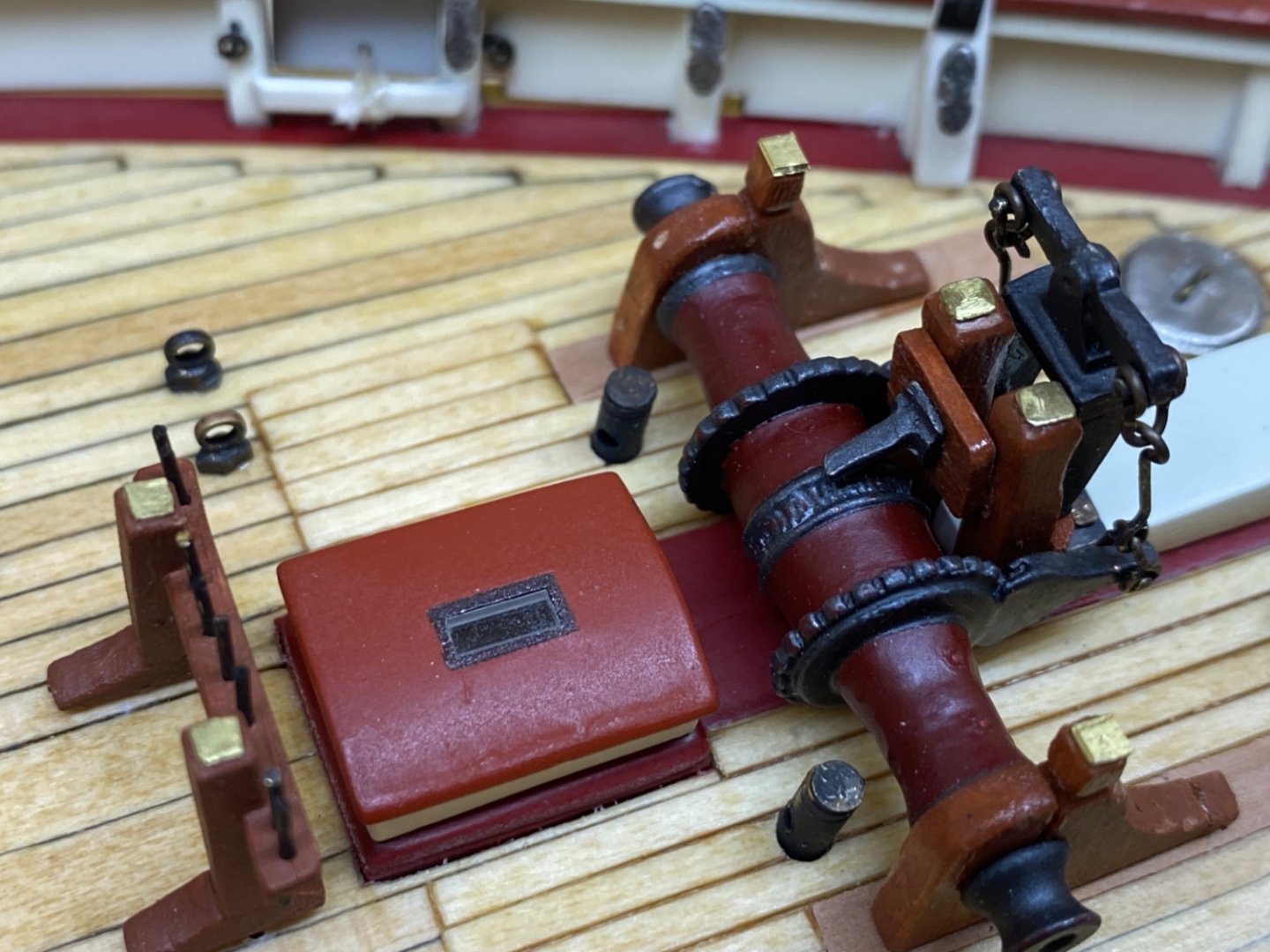
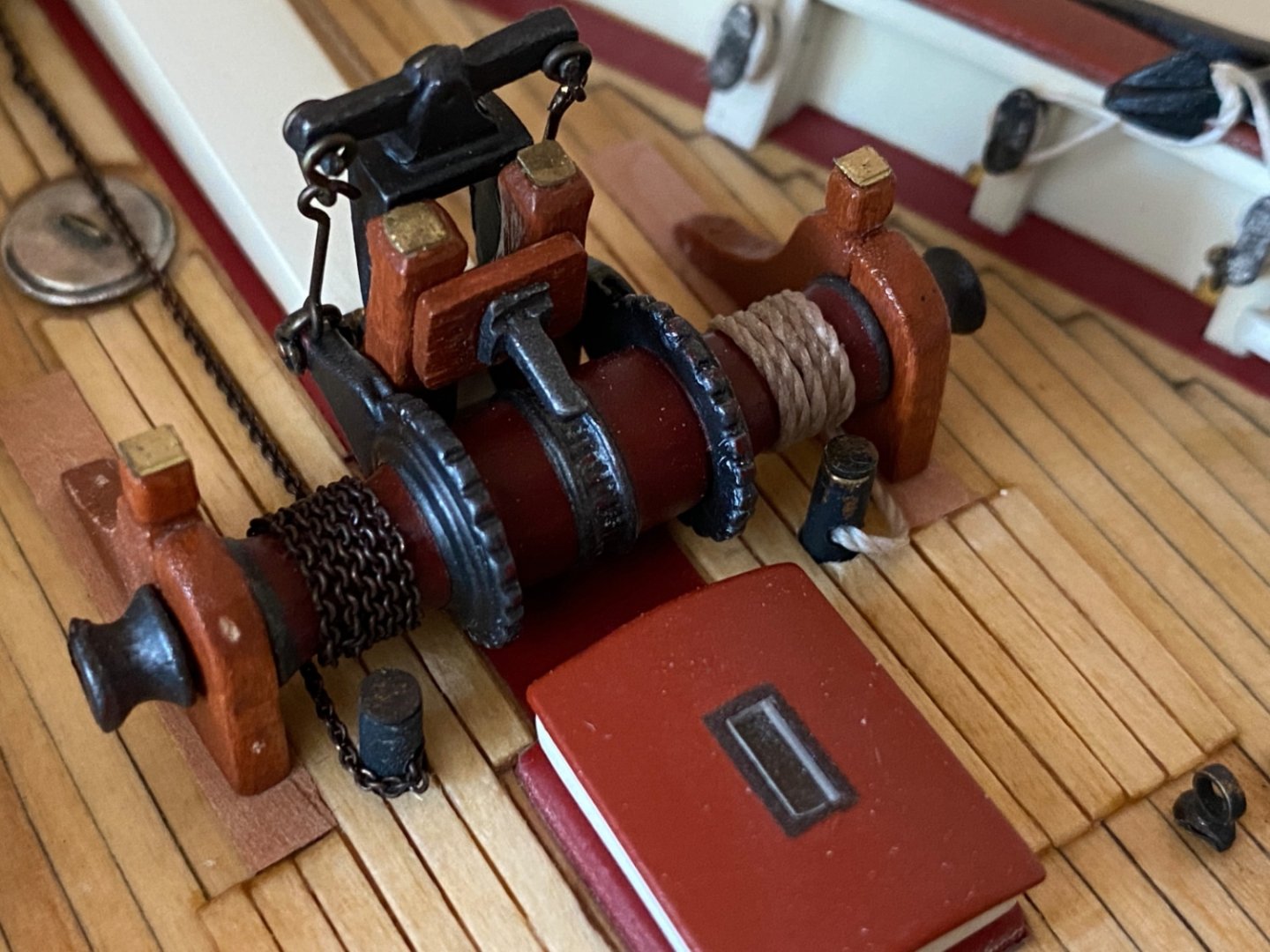
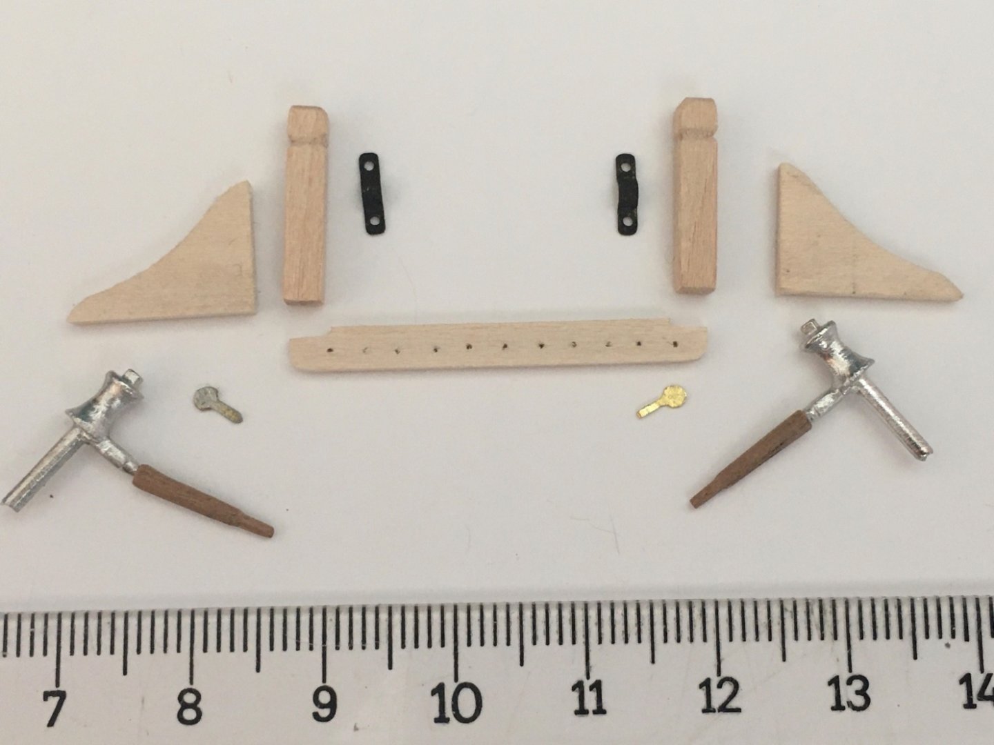
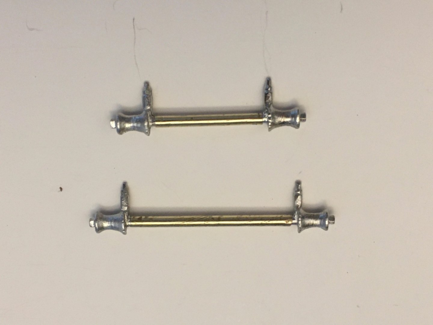
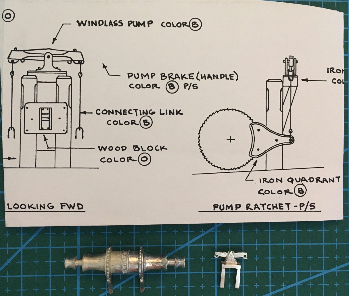
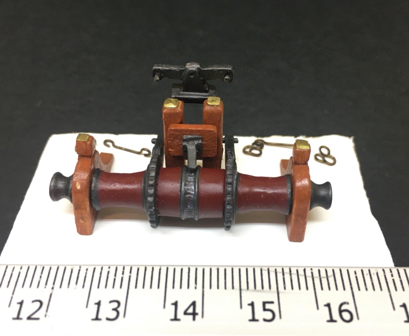
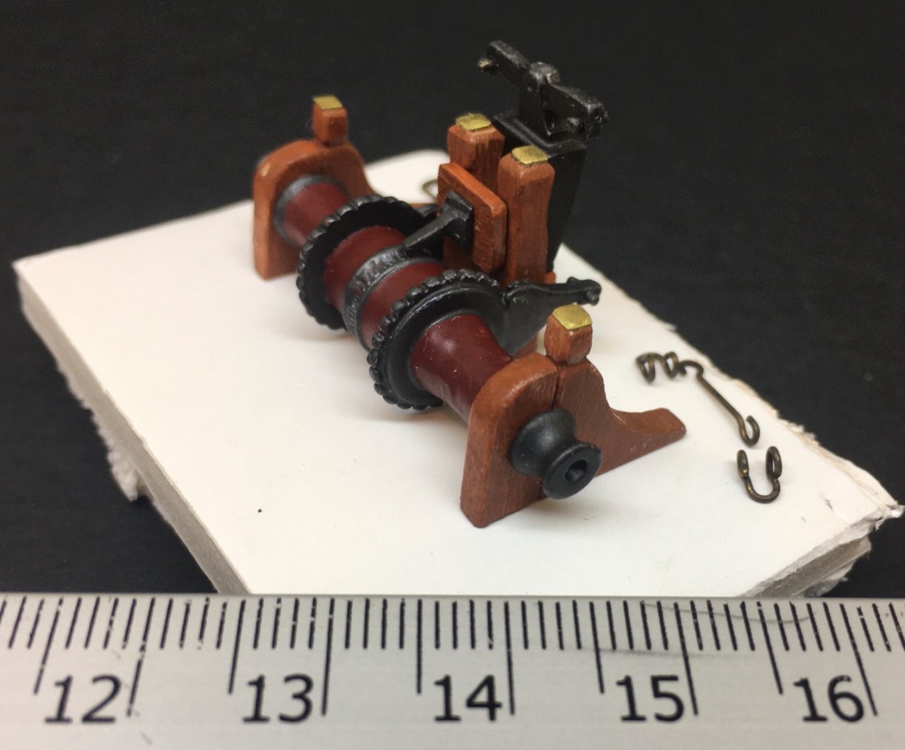
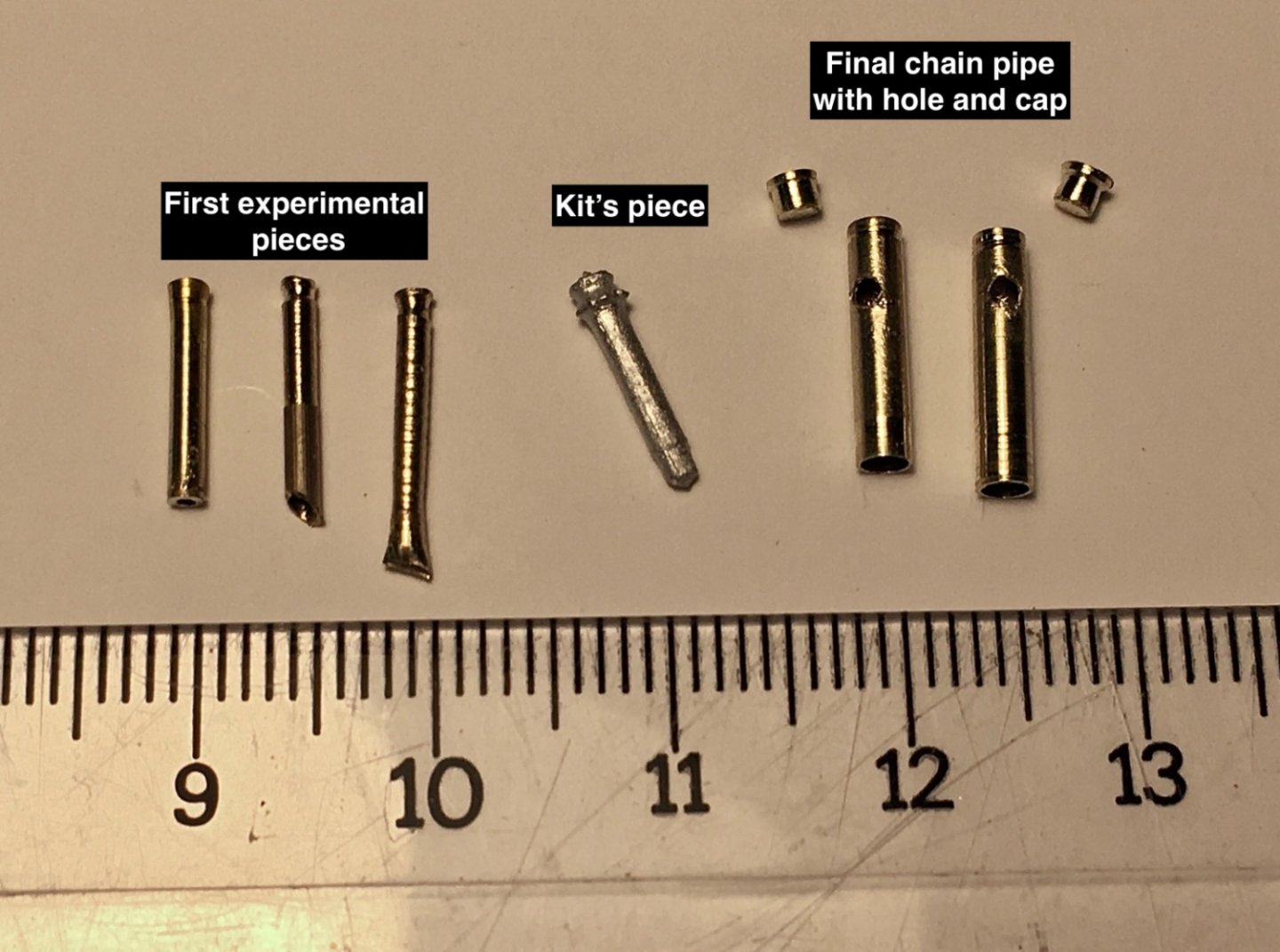
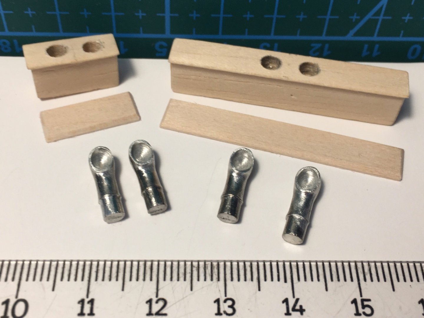
The windlass is mainly two metal parts. Those parts are sanded and cleaned. Samson posts and connecting links are prepared. Holes for those links must be drilled in windlass quadrants and pump handle brackets. Holes for nails under the samson posts and windlass riding bits were opened. The corresponding holes on the deck will be opened after the final location of the windlass system was decided. Port and starboard riding bitts were glued together and the windlass system is temporarily mounted on a 1 cm thick photo block and was put in a closed organizer box. At this stage the chains pipes for anchor chain (port) and anchor rope (starboard) were scratch build as the pieces given by the kit did not feel realistic. The new pieces were prepared from brass tubing and the caps were made from brass rods by turning and shaping them in Dremel 4000 fixed on Dremel workstation. Holes on the sides of the pipes were drilled. The chain and rope will go in from those holes to the space below deck in the final installment stage.
- 114 replies
-
- 3
-
-
- Pride of Baltimore II
- Model Shipways
- (and 1 more)
-
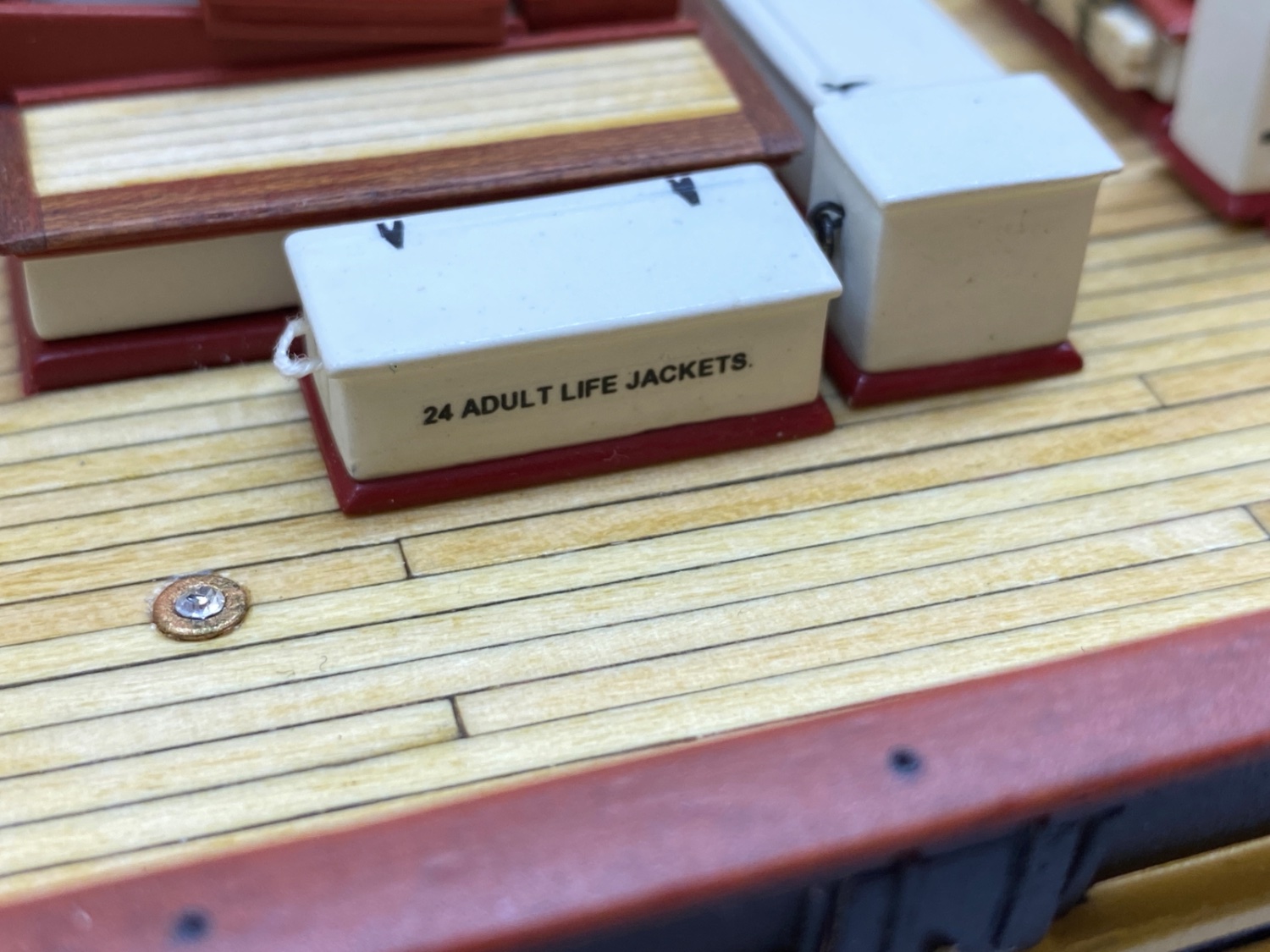
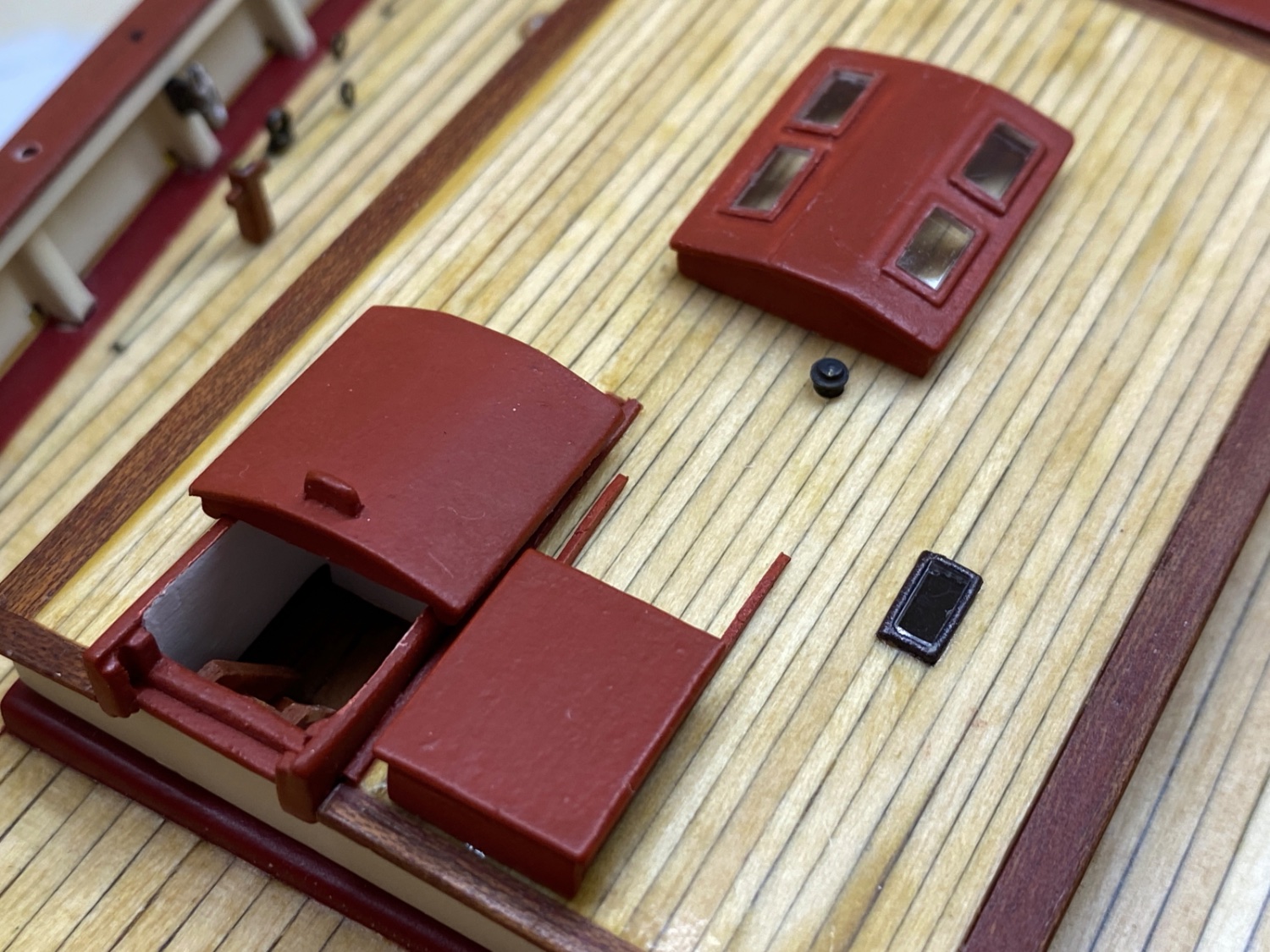
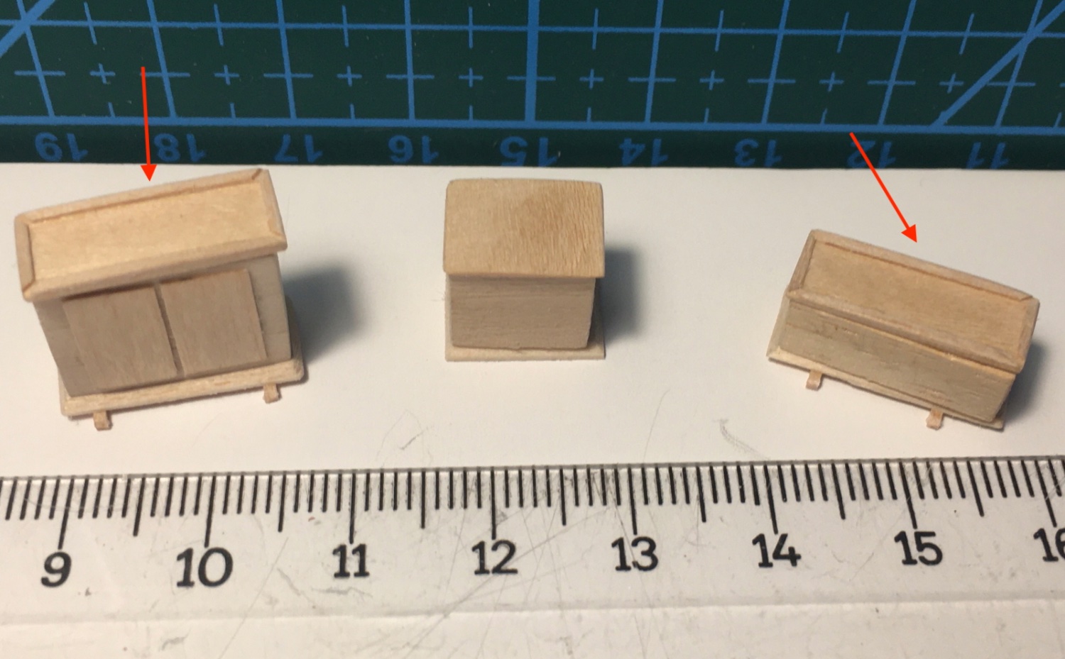
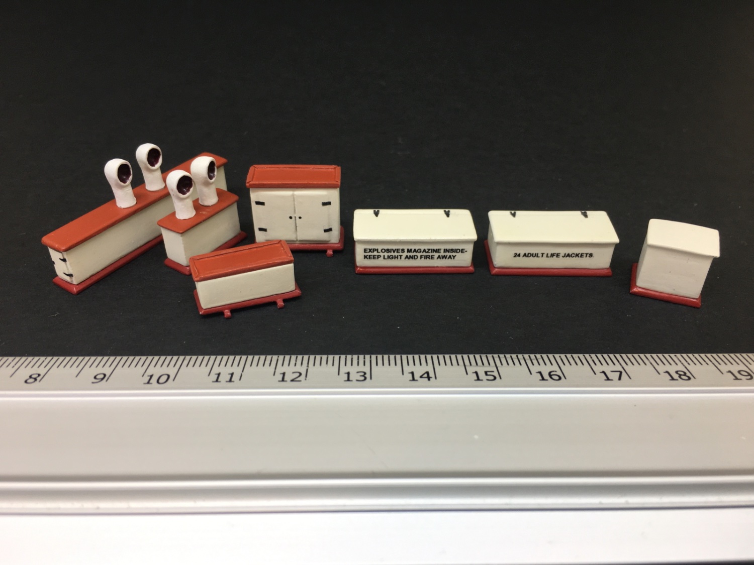
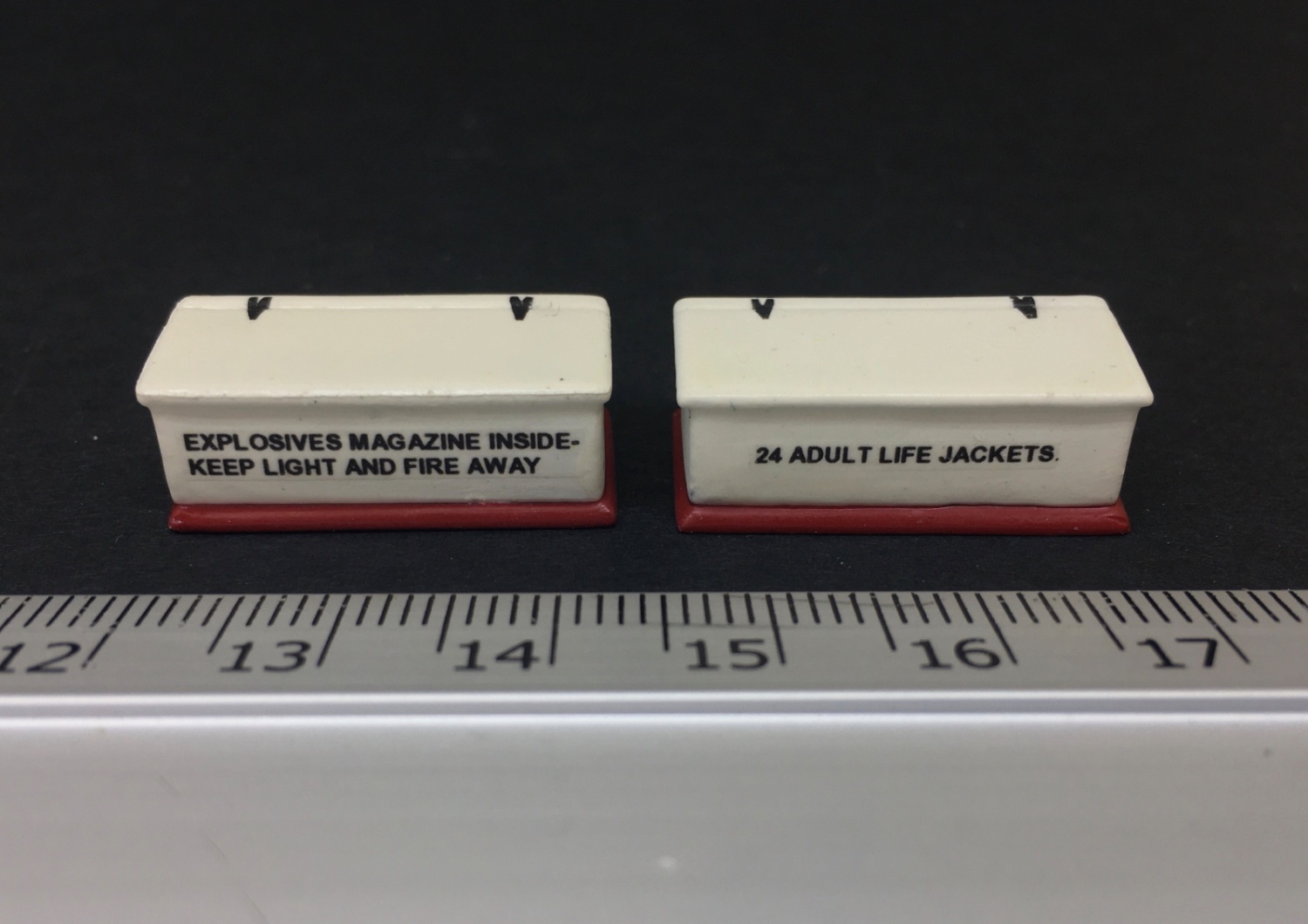
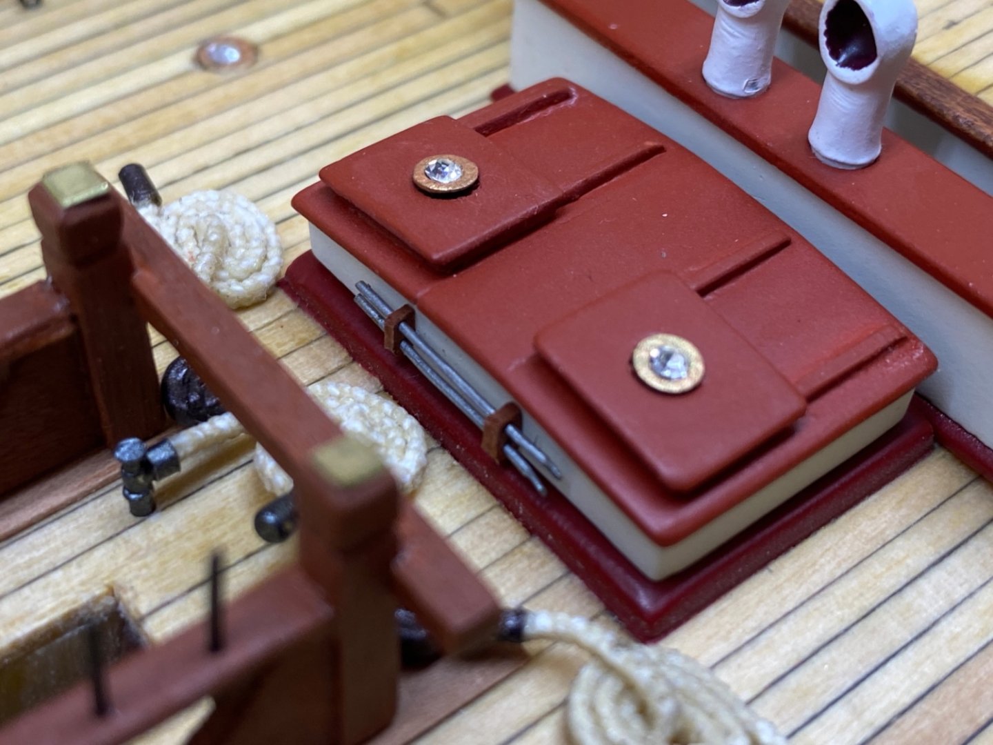
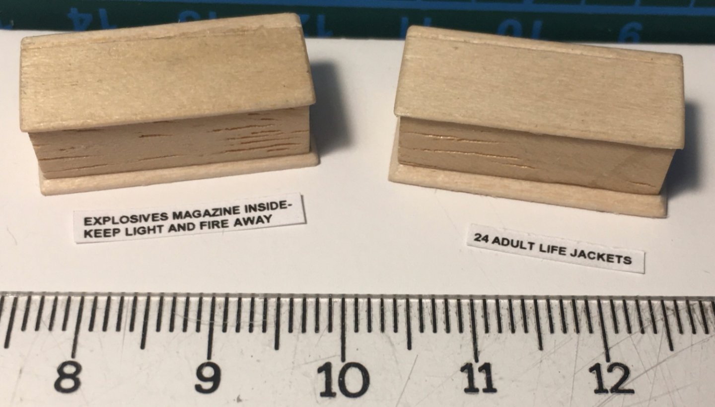
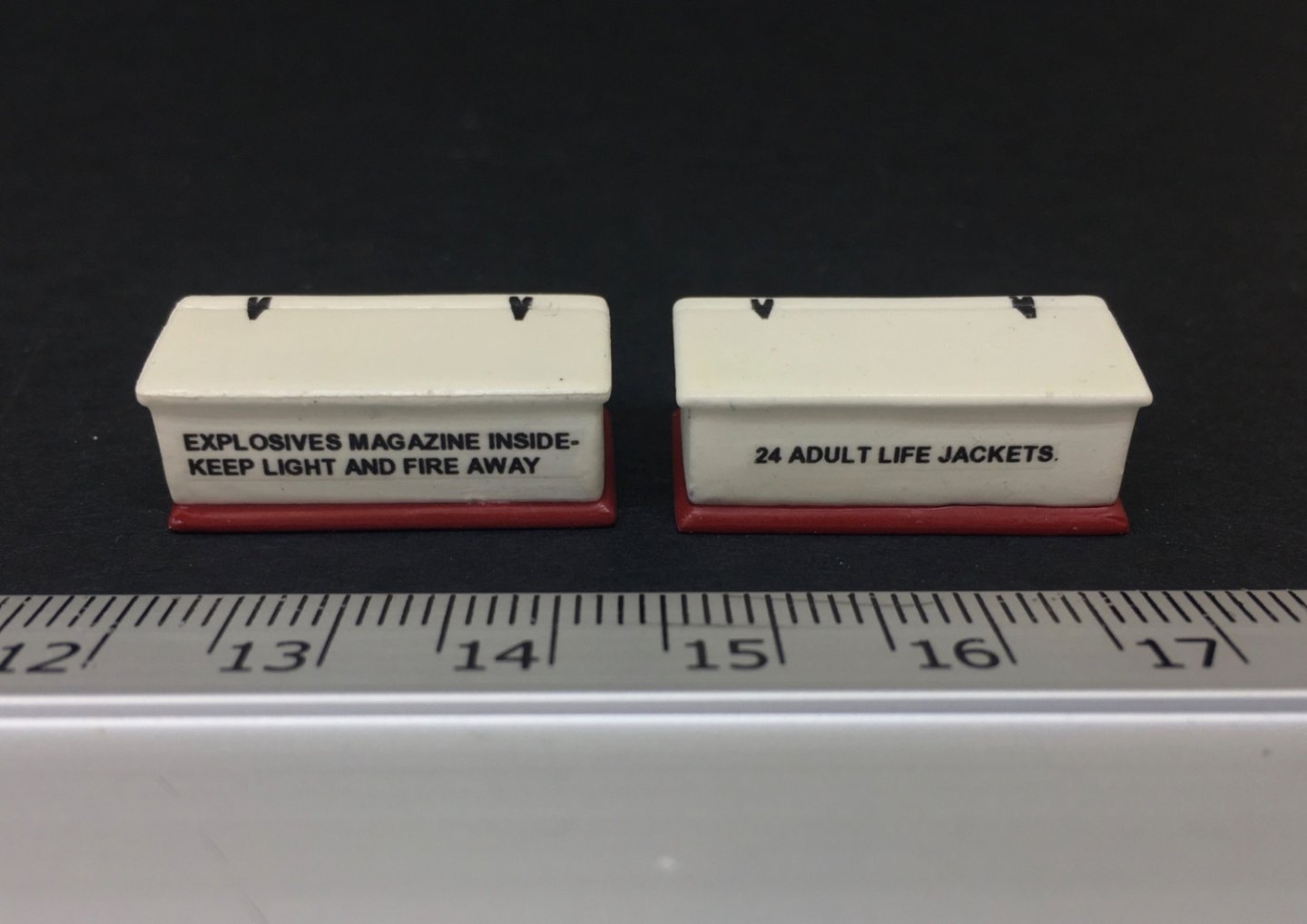
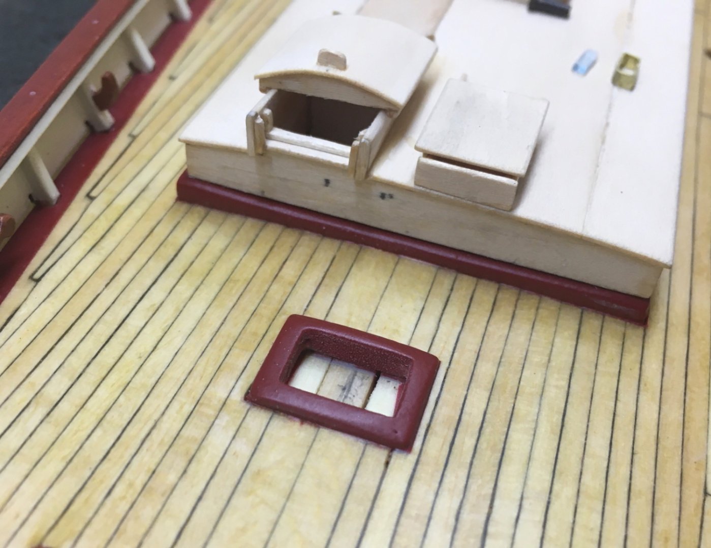
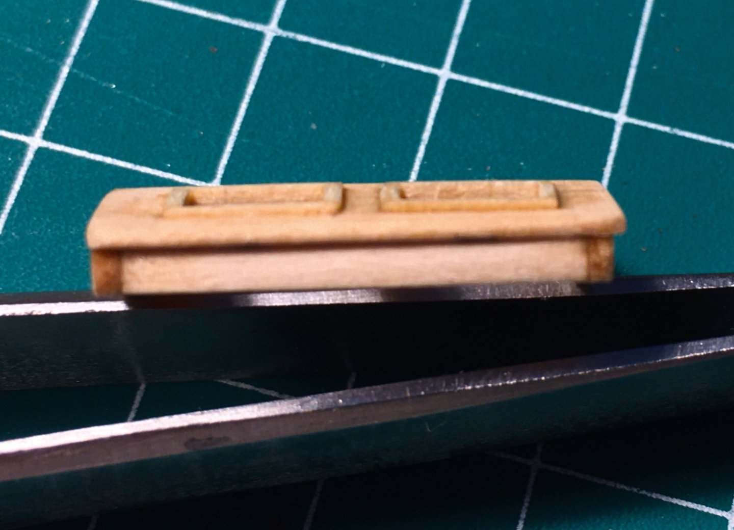
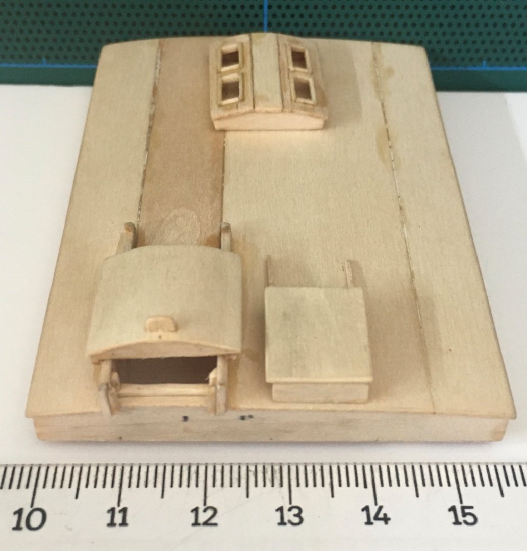
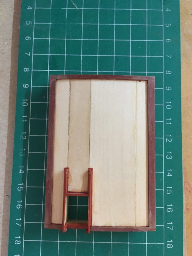
I'll move on with the ventilation boxes and deck lockers. There were two ventilation boxes. They were were prepared from basswood wood blocks. Contrary to the deck lockers , their top parts were glued before painting in order to drill out the holes for vent cowls properly . However bottom part were glued after painting. Although the instructions dictate that these two boxes have feet under them, it can easily be observed from the recent photos only the short one has feet. I decided to built them without feet. There were 5 deck lockers. Their bottom and tops were glued after painting. The tops of the two of them (red arrows) were different from the other three as they have a border of thin strips with openings at the corners. Those two lockers also have feet under them as a difference from the other three. The lettering of two of the boxes were prepared as decals. The font size of the lettering was 3.5 (MS Word font sizes). Hinges were made from black decal pieces. All the doors on the lockers and vent boxes were made from 0.3 mm thick wood sheets. Rope handles were later made before the lockers final instalment. After painting


- 114 replies
-
- 3
-
-
- Pride of Baltimore II
- Model Shipways
- (and 1 more)
-
You are right Yves. There will be many more examples of scratch building in the later stages. However I enjoyed the challenges throughout the building journey.
-
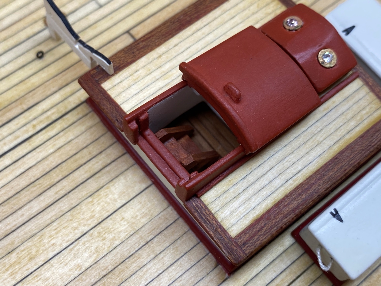
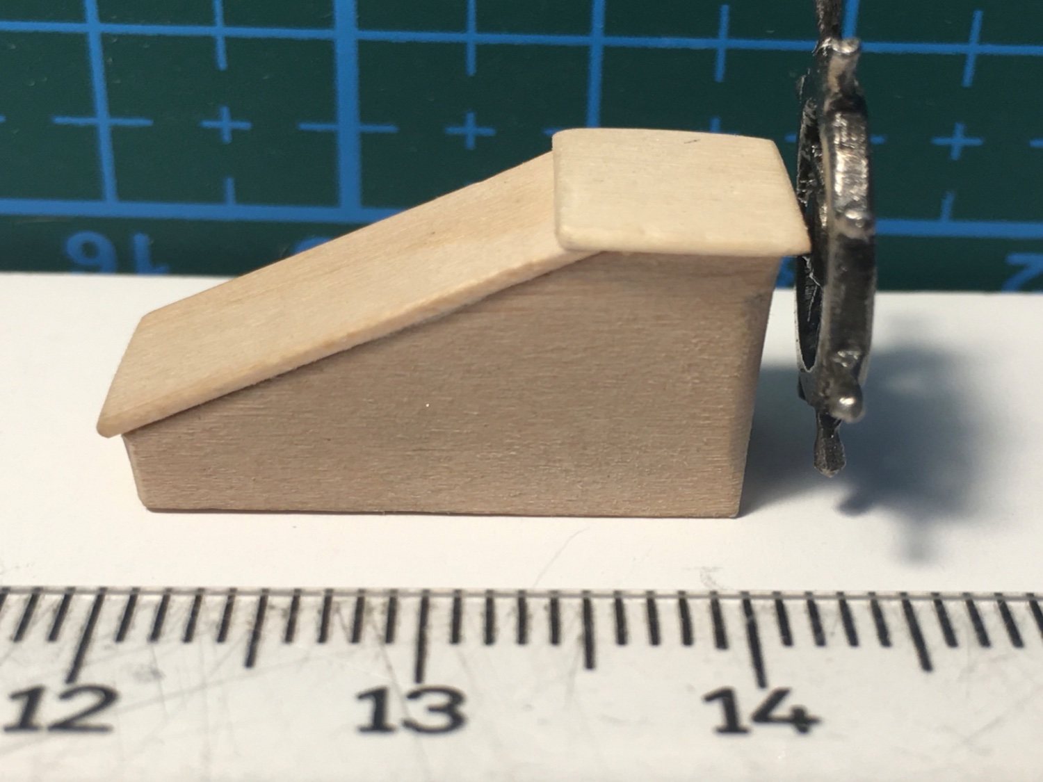
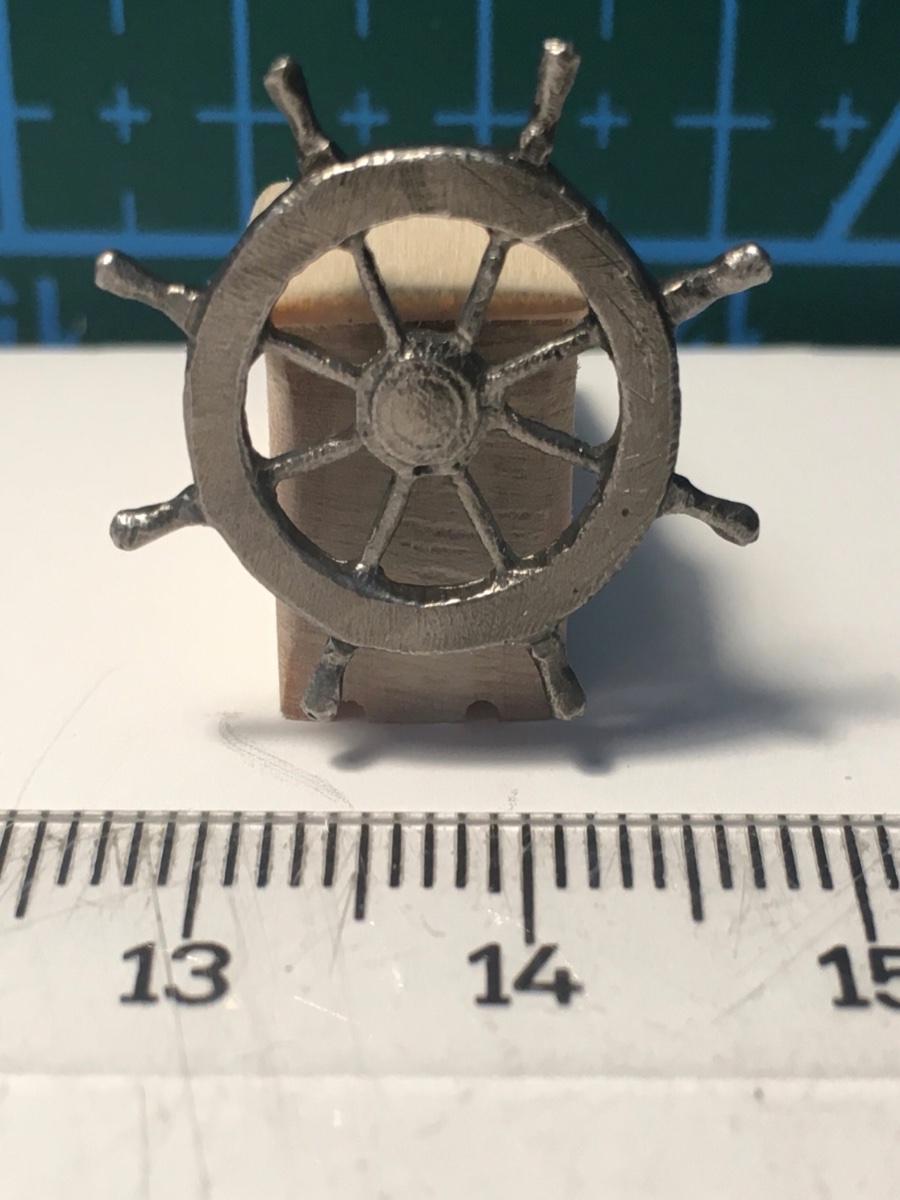
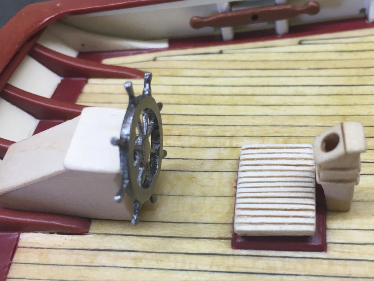
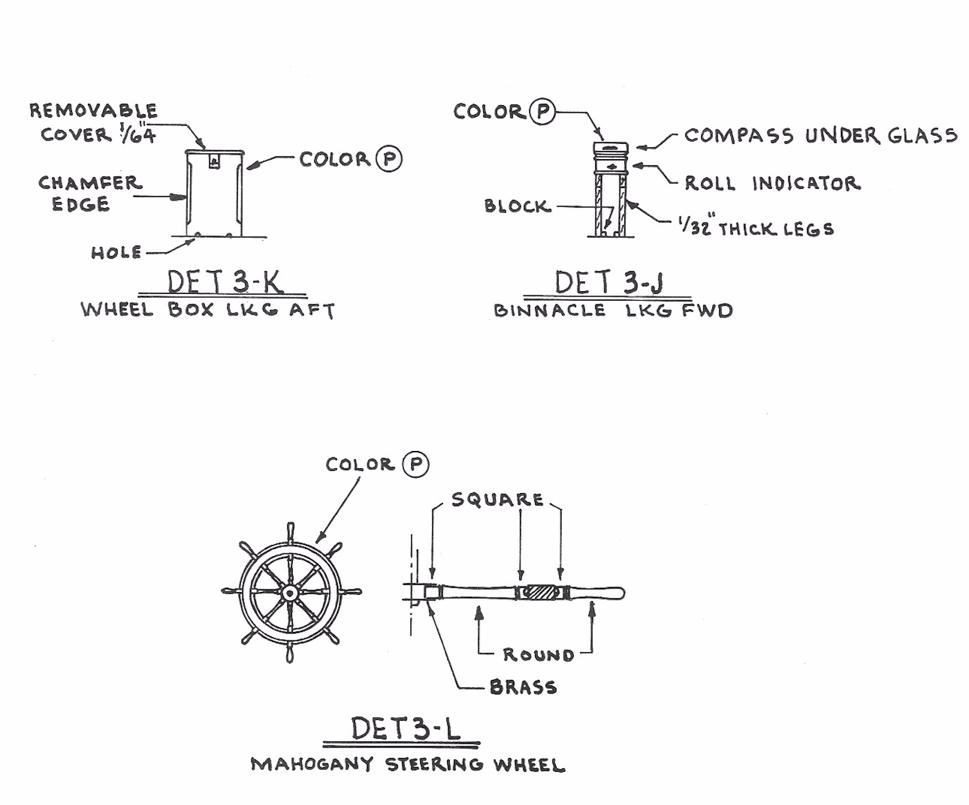
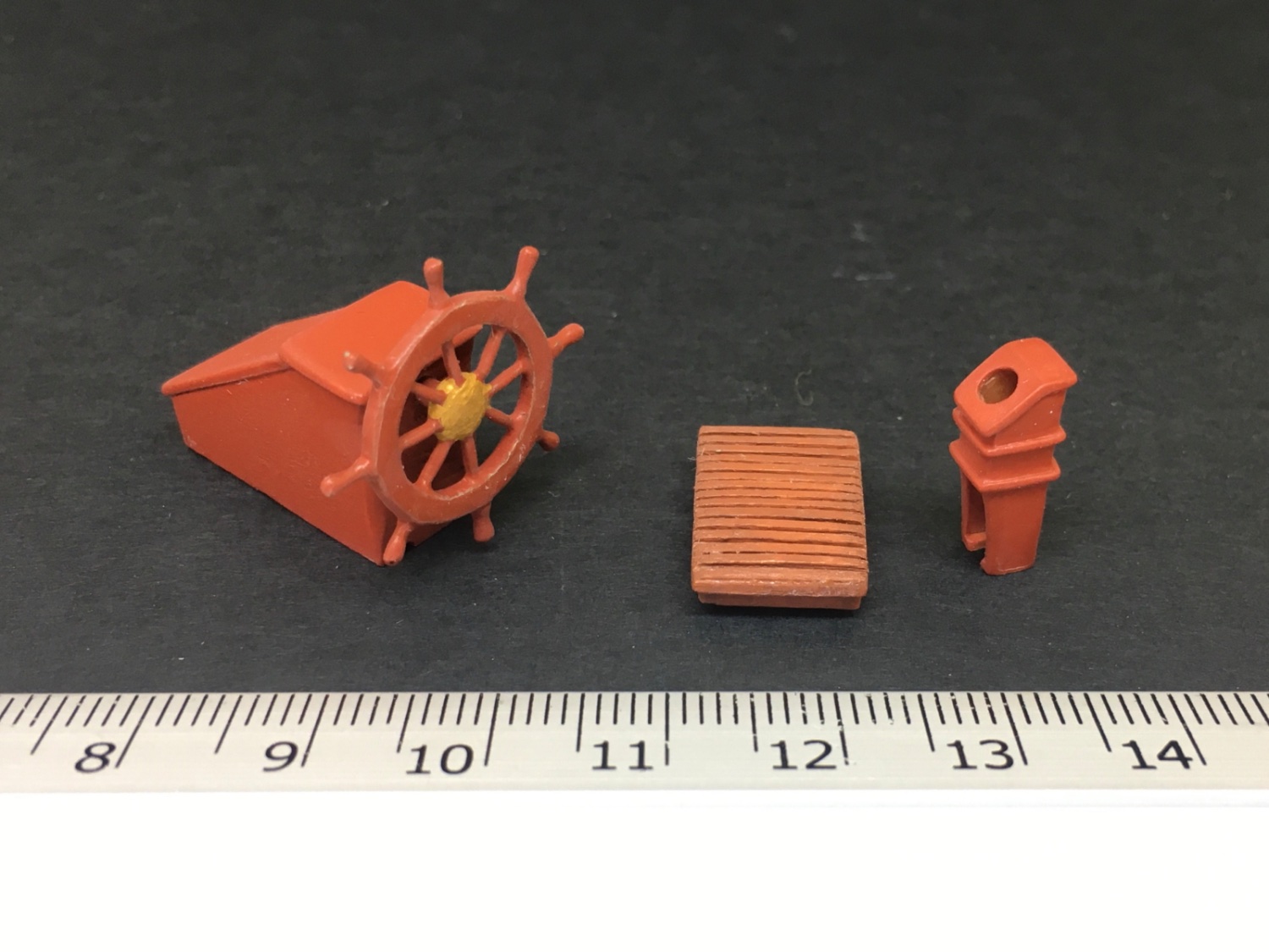
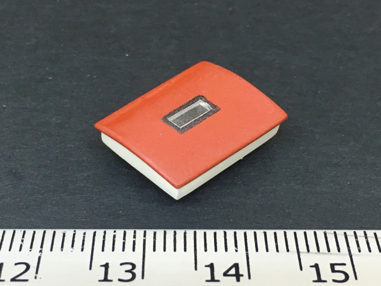
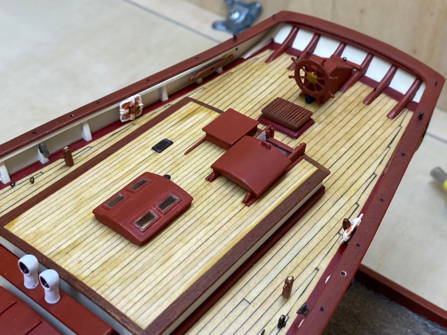
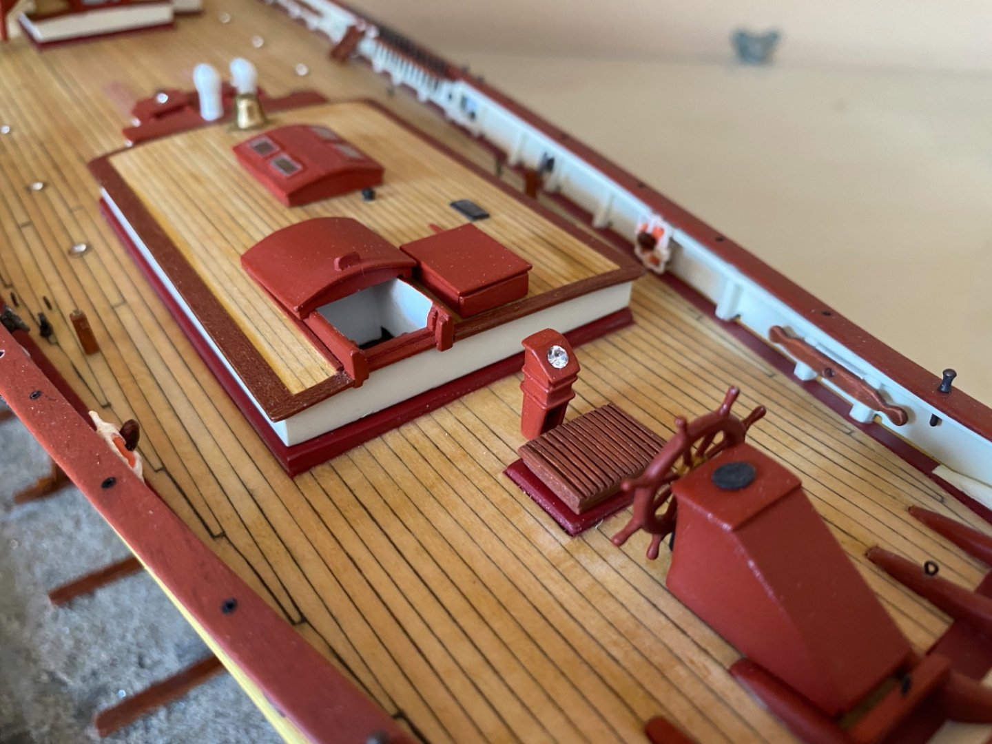
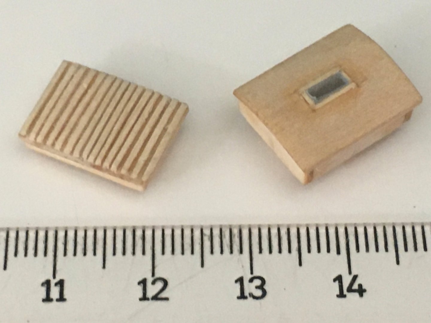
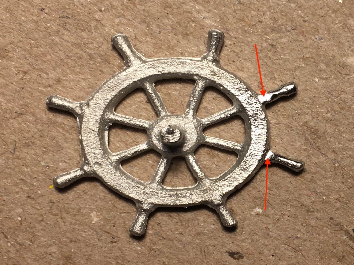
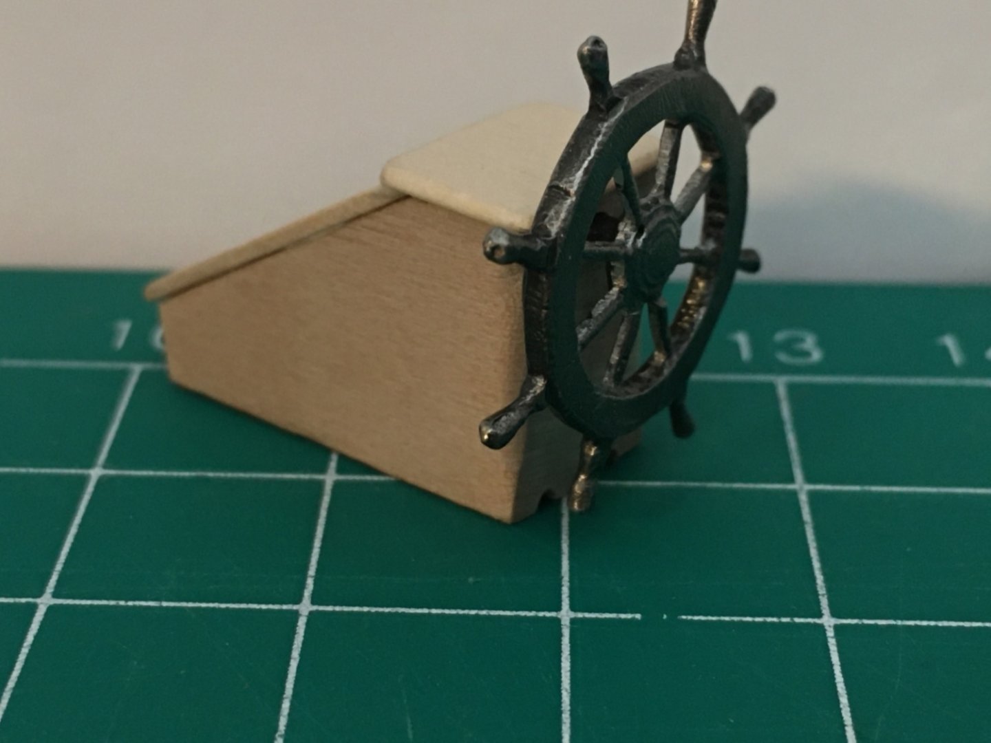
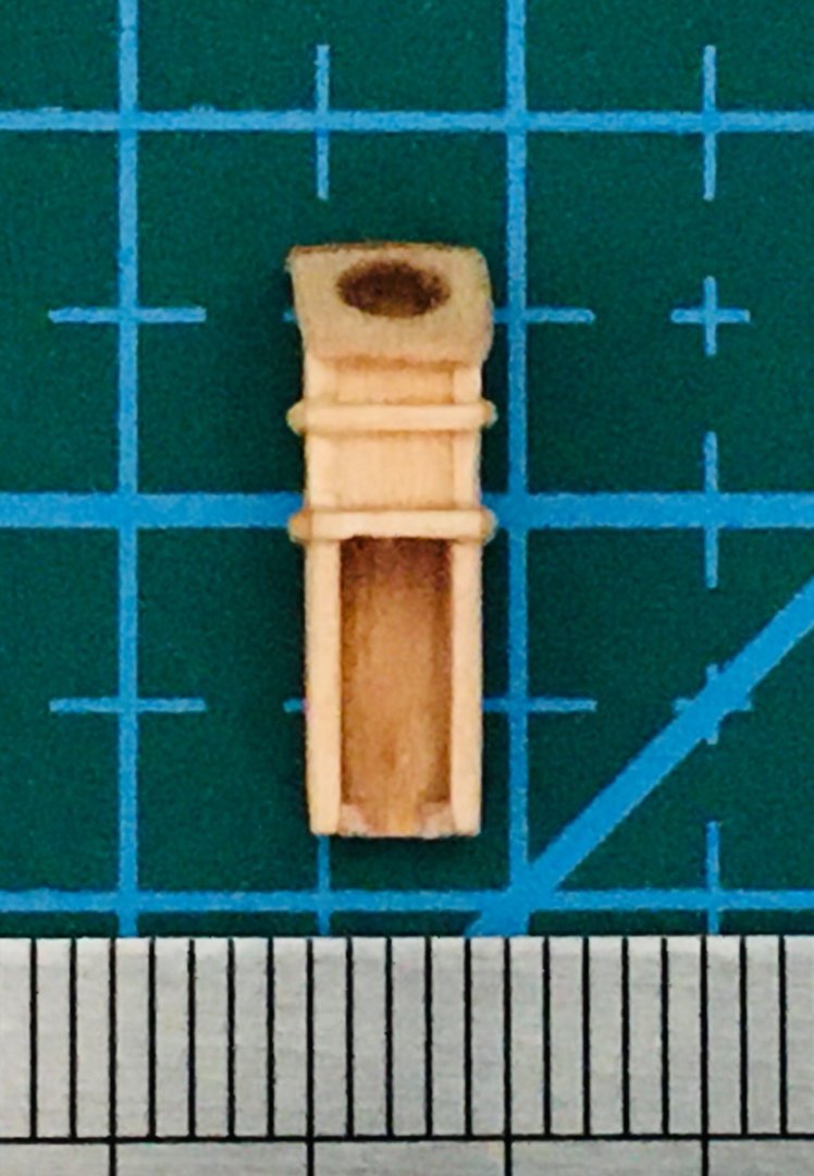
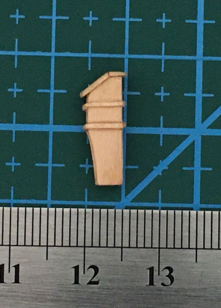
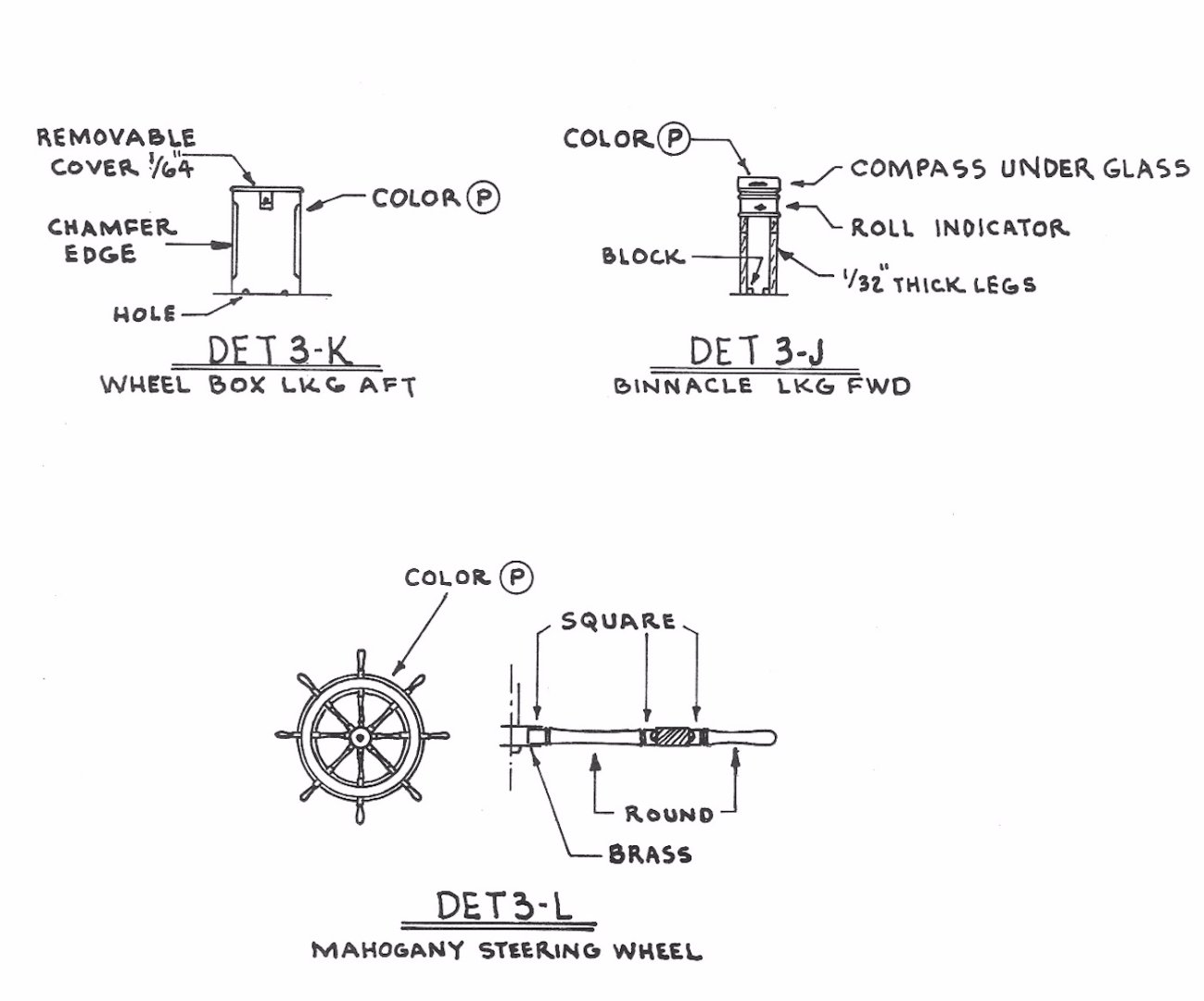
The two hatches at fore deck and aft deck were prepared. I decided to skip the moving hinges at these structures too. The window glass on the fore hatch is plexiglass. The wheel was filed to the final shape. Red arrows show the square filed areas. The wheel box was made from a wood block. The two tops were added later. The binnacle was made from several parts glued together. Finished photos


- 114 replies
-
- 4
-
-
- Pride of Baltimore II
- Model Shipways
- (and 1 more)
-
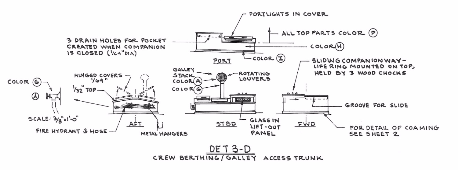
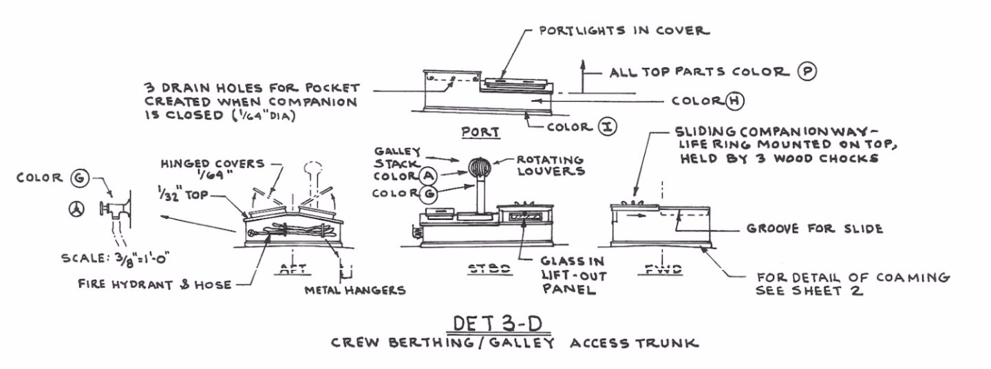
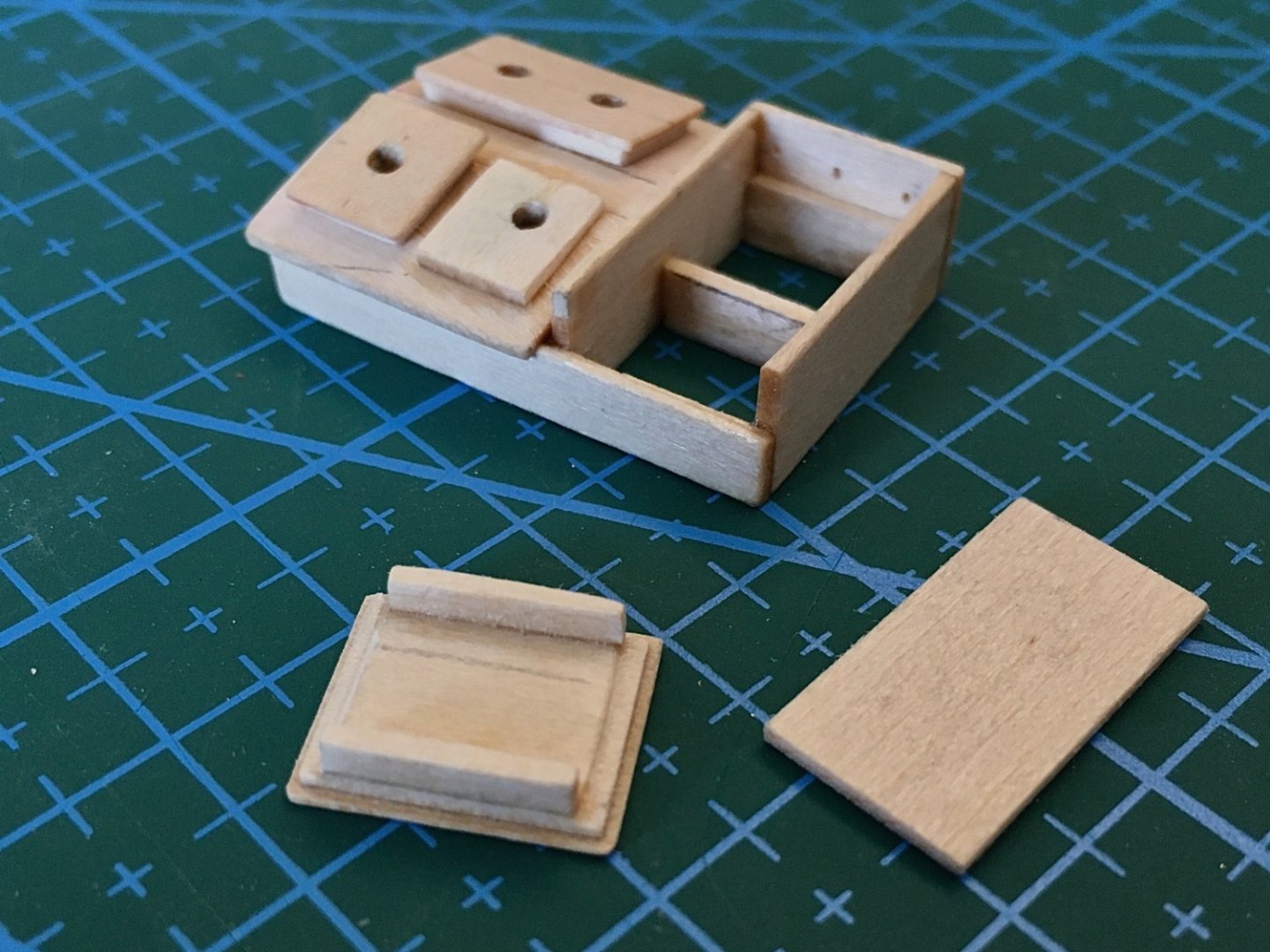
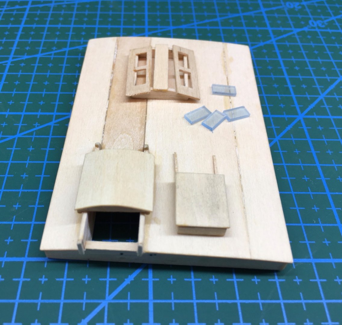
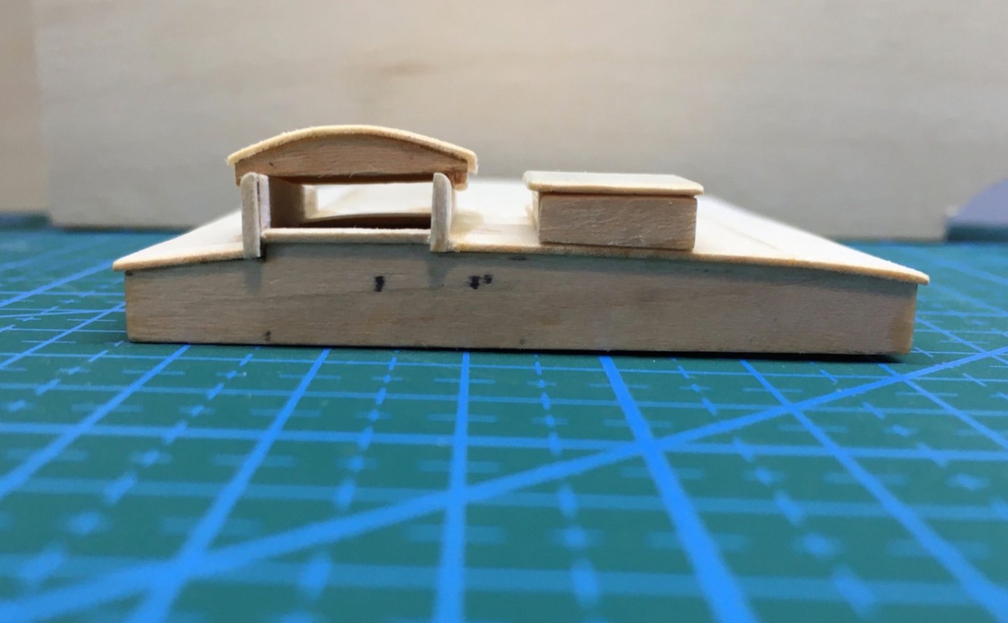
The fourth cabin top was Crew berthing/galley access trunk. The structure of this cabin top was a bit complex when compared to engine room top. The hose for the fire hydrant was made from cloth. The hose nozzle and the connection piece on the hydrant were made from brass rod and tubes turned in Dremel 4000 fixed in Dremel workstation. A brass rod was placed. After drying the brass rod was removed. The tips of the prepared hose were trimmed to fit the hydrant and the hose tip. As there are two fire hydrants on the ship another piece set was prepared. The finished photos


- 114 replies
-
- 3
-
-
- Pride of Baltimore II
- Model Shipways
- (and 1 more)
-
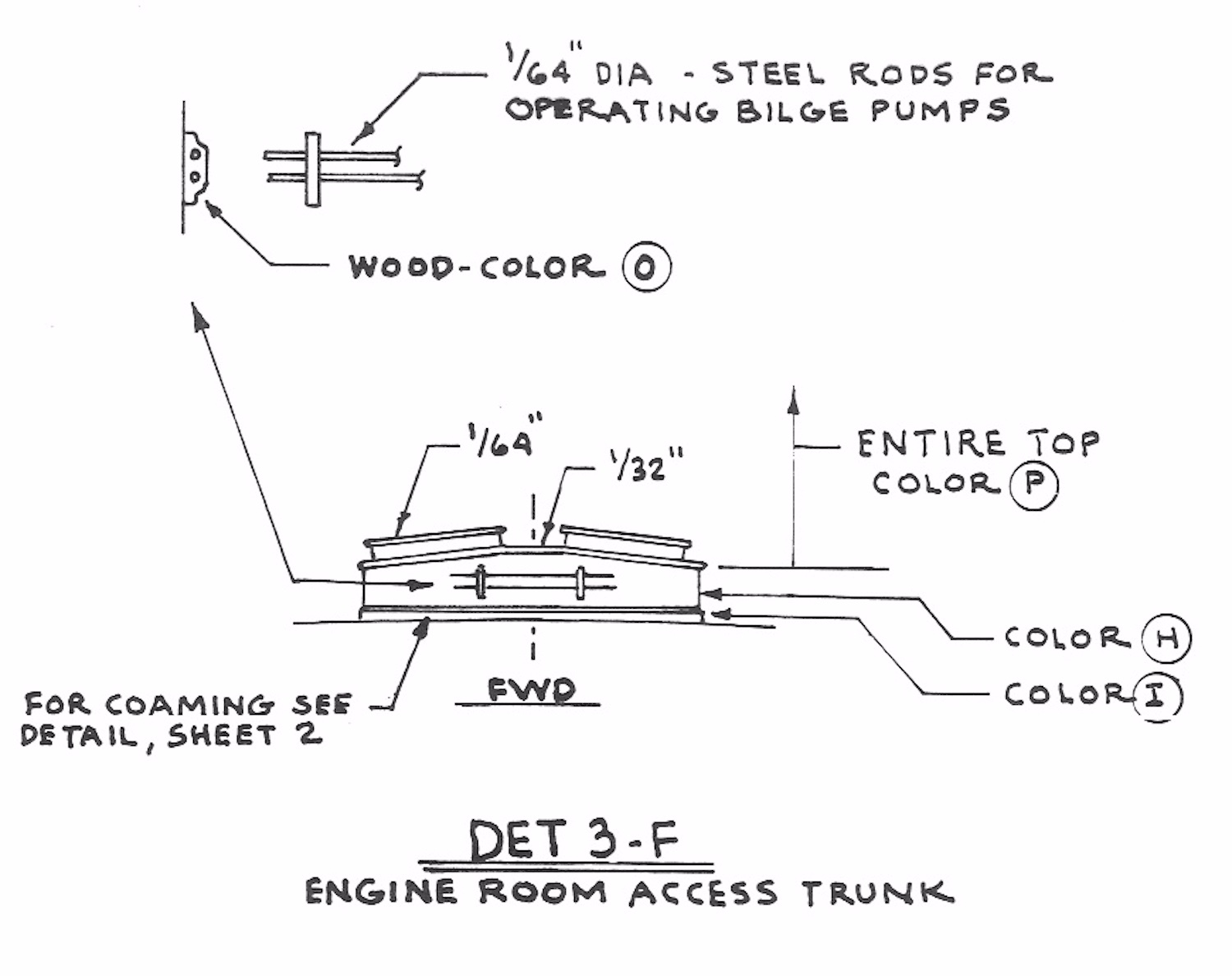
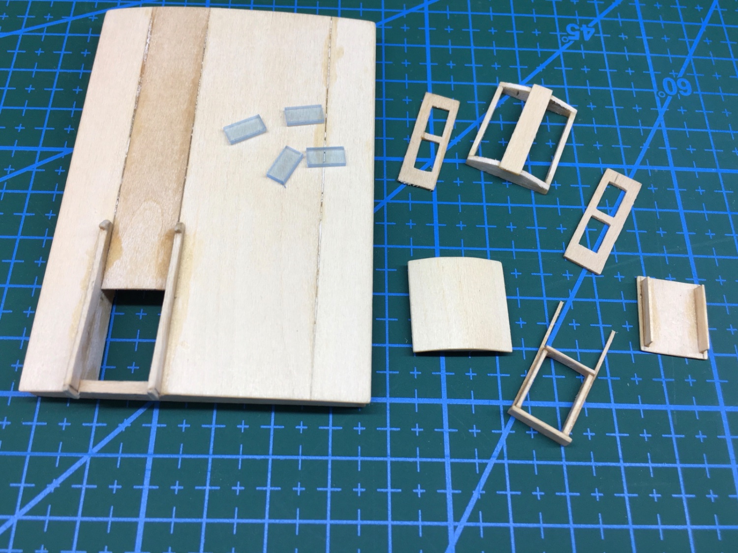
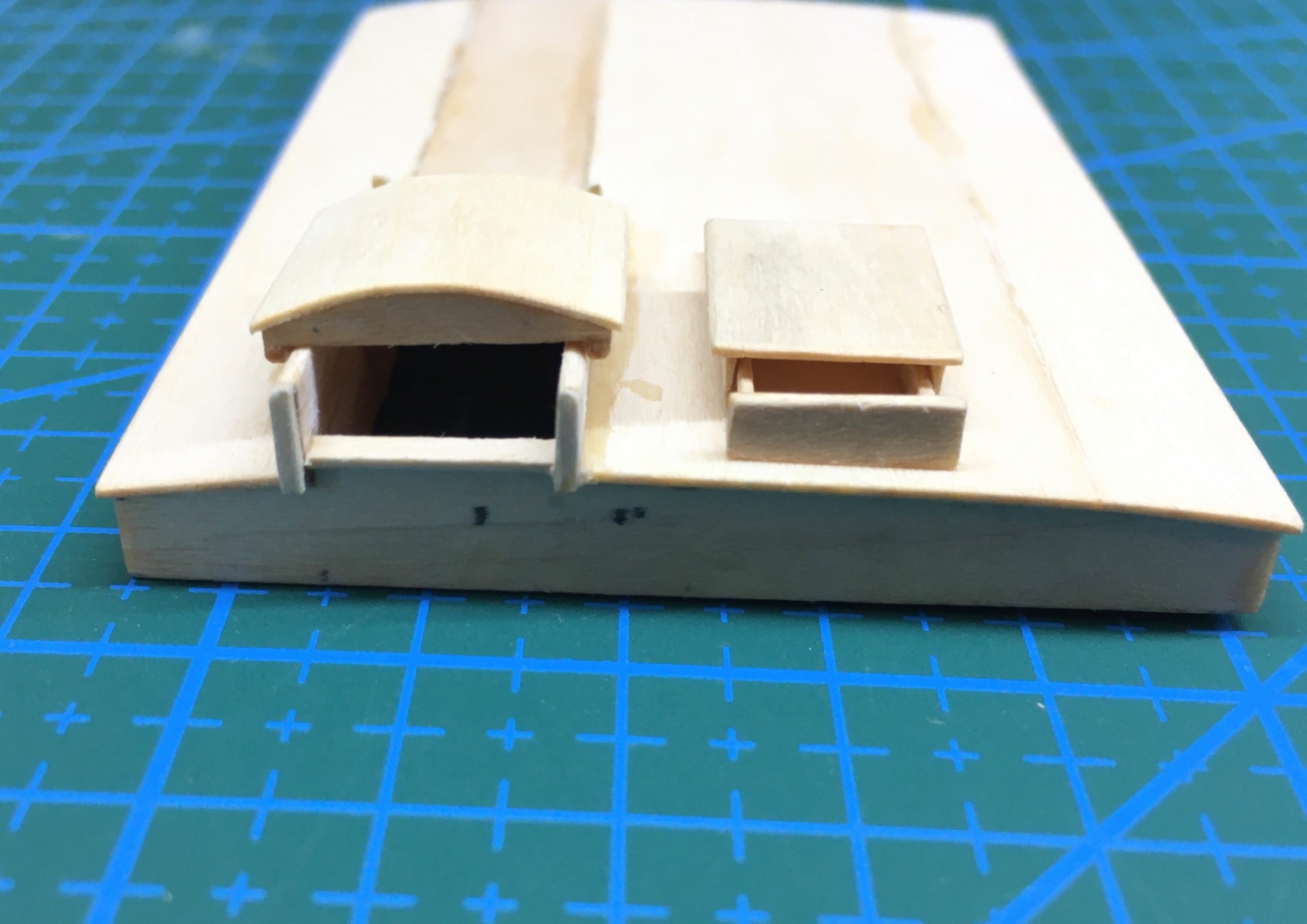
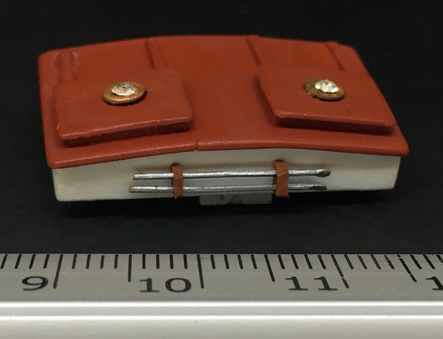
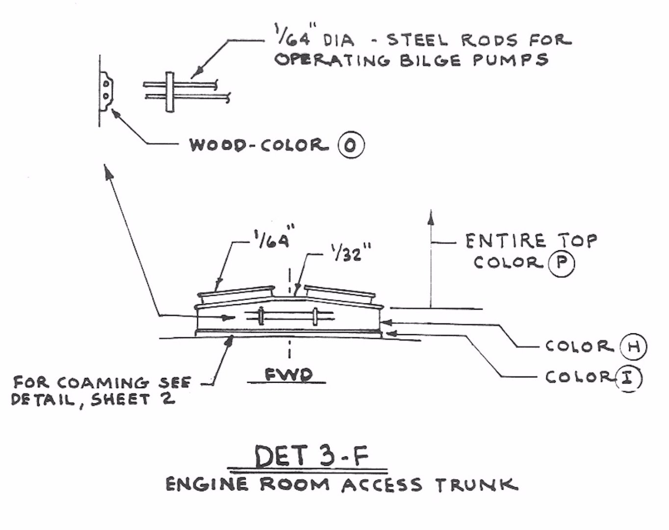
Engine top was also prepared in the same manner. Side walls first followed by top pieces and finally the sliding covers and rails. Two holes for light passage were drilled. The curved flanges of the two airports, to be inserted to those holes, were filed . Finished photo. On the fore wall of the structure the two handles for bilge pumps were placed.


- 114 replies
-
- 4
-
-
- Pride of Baltimore II
- Model Shipways
- (and 1 more)
-
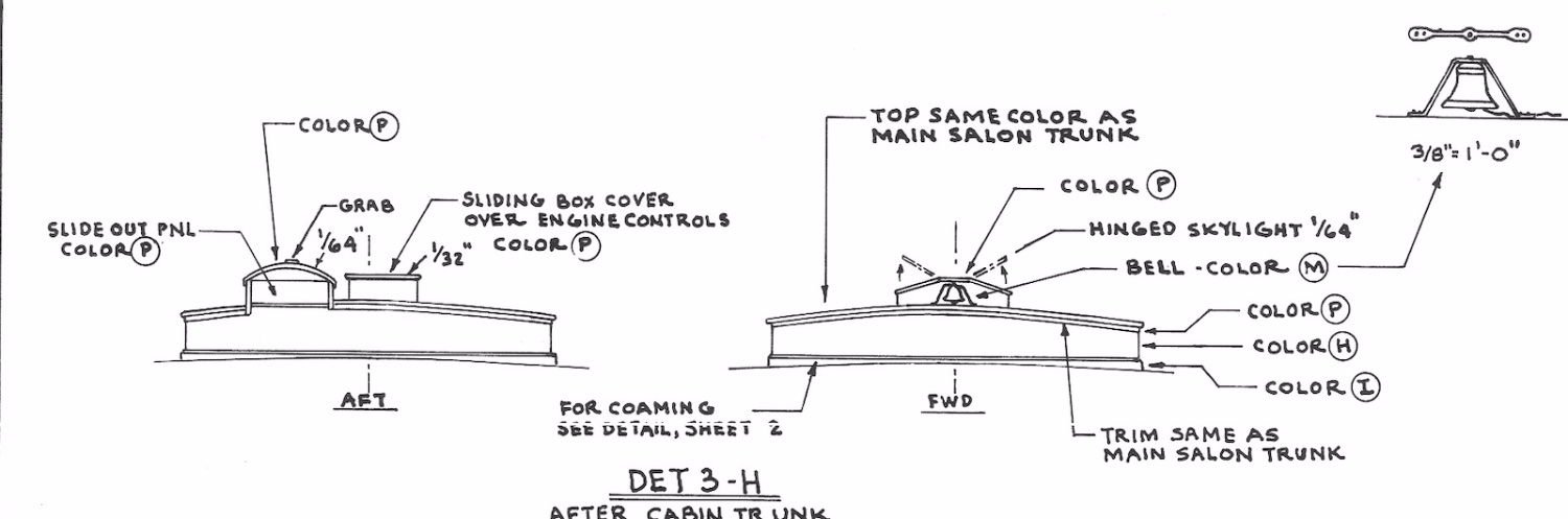
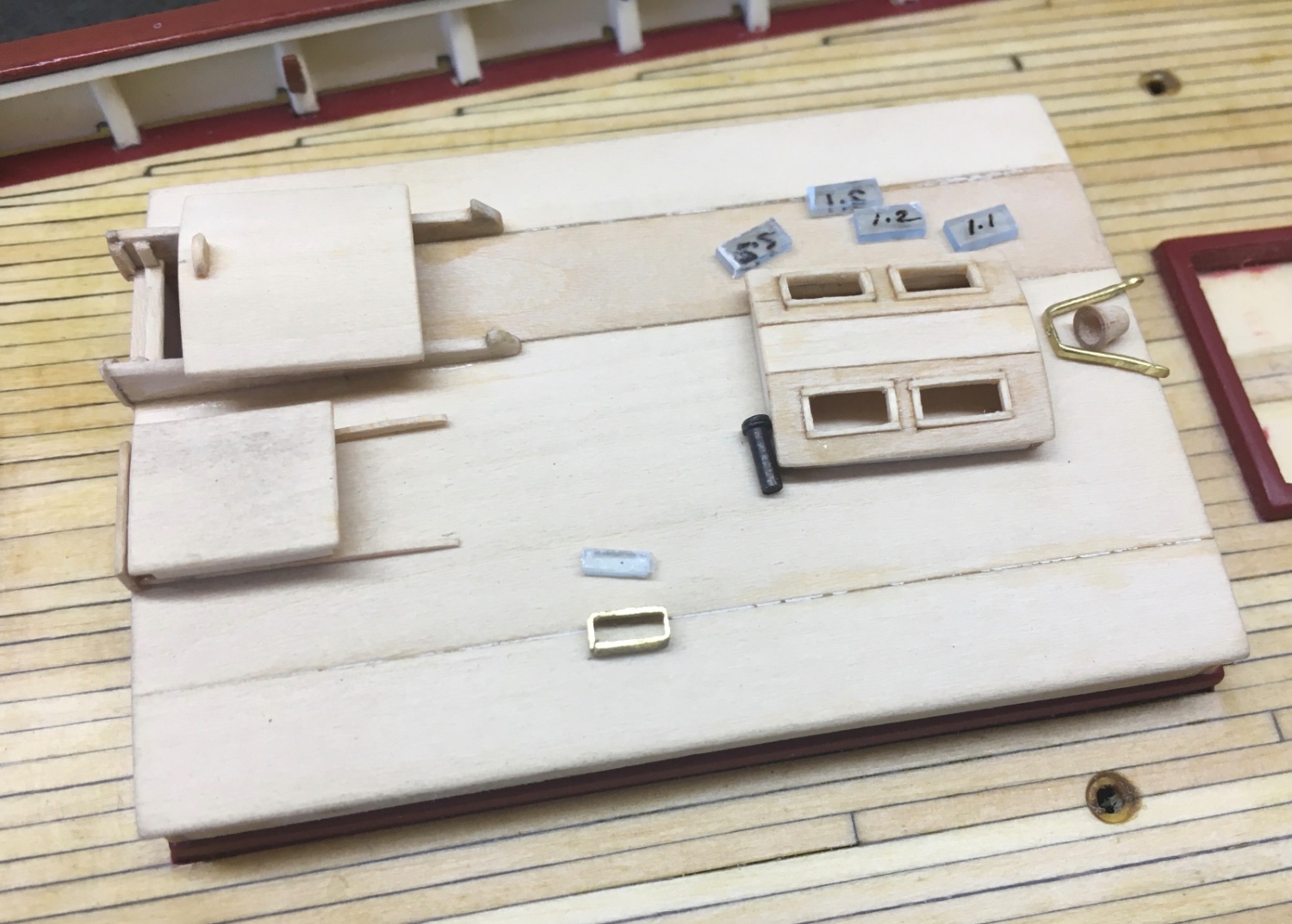
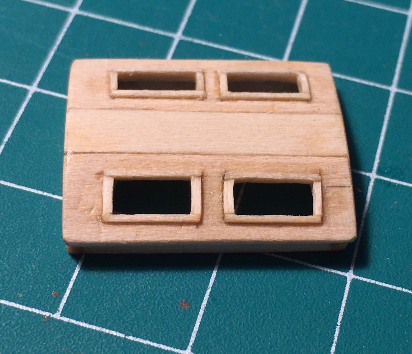
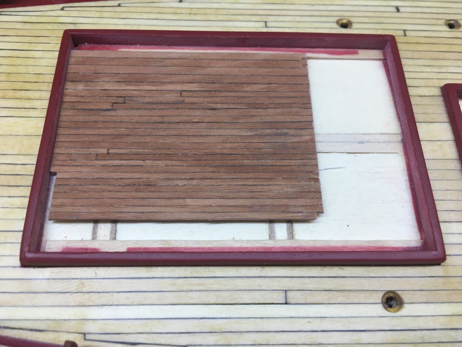
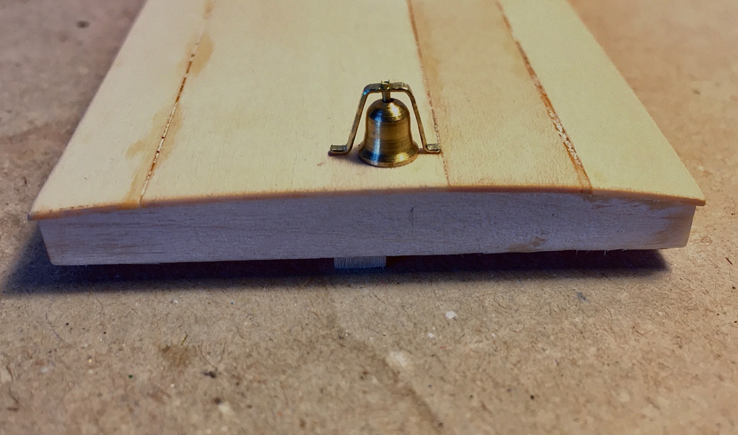
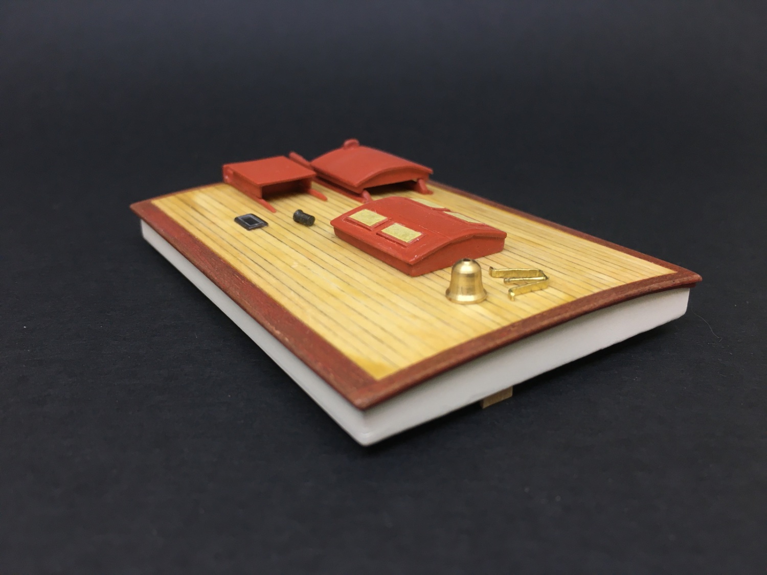
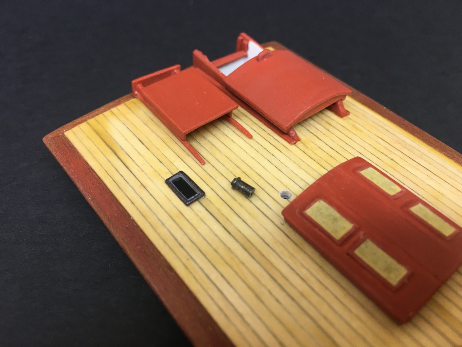
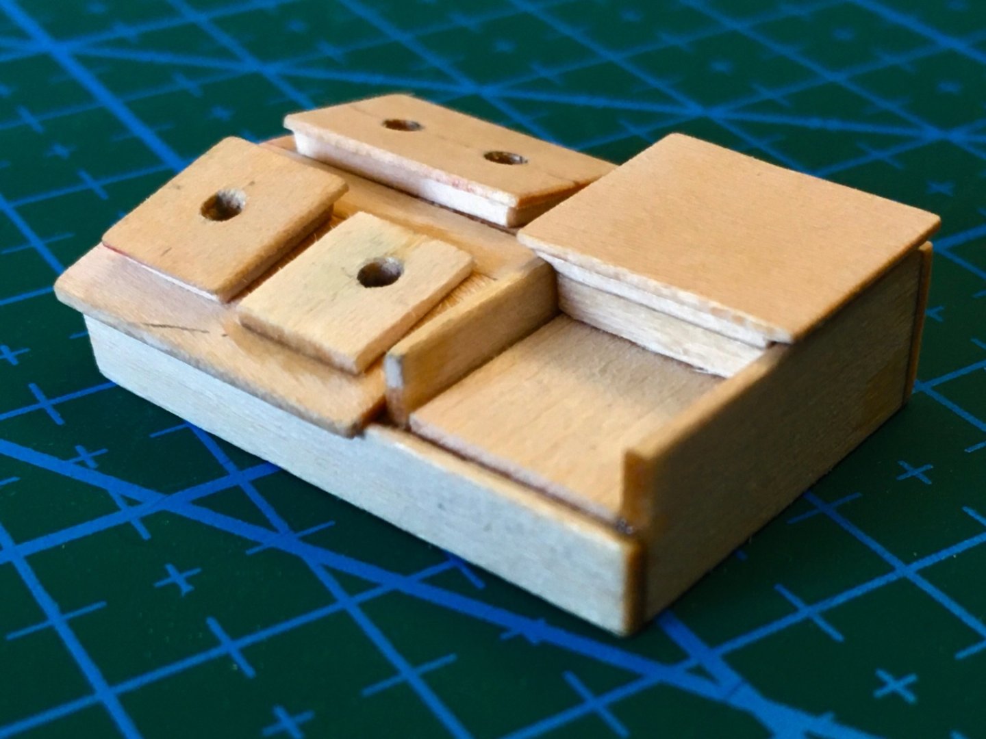
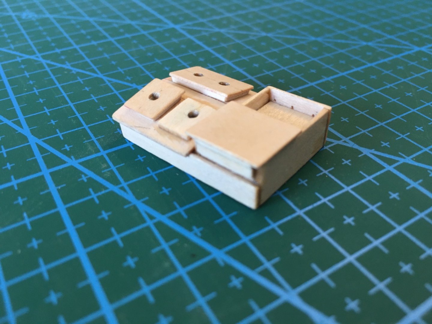
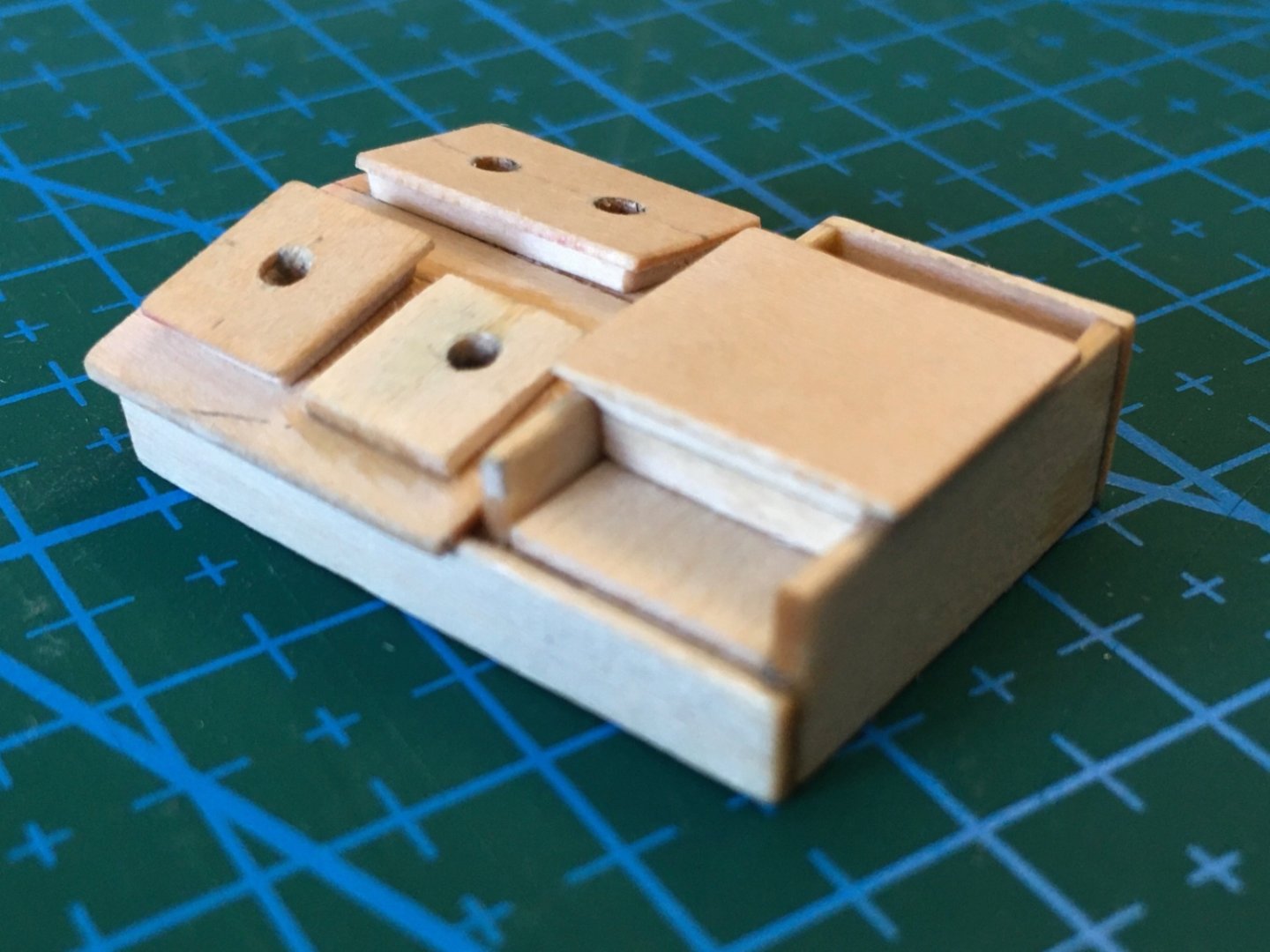
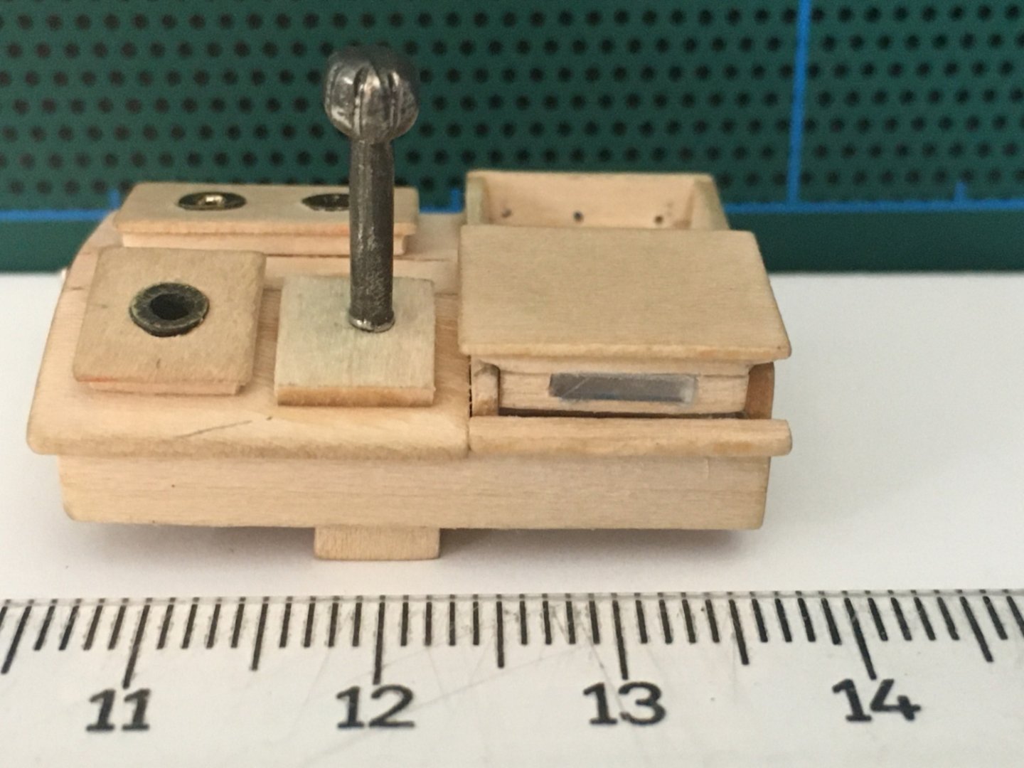
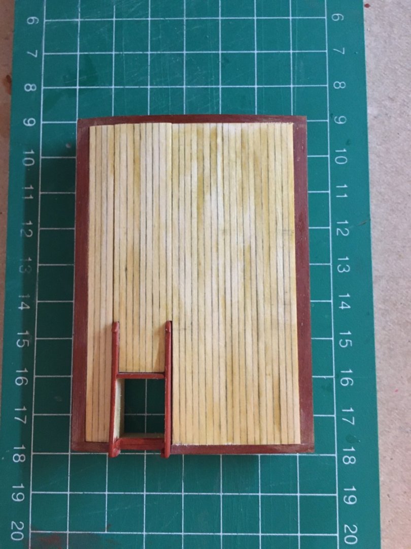
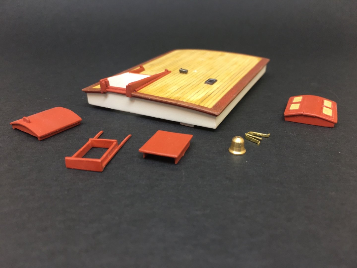
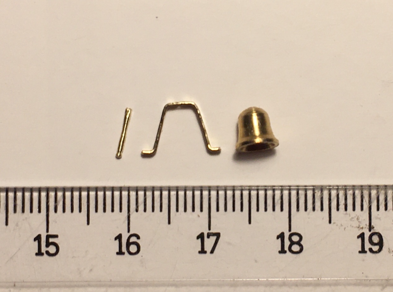
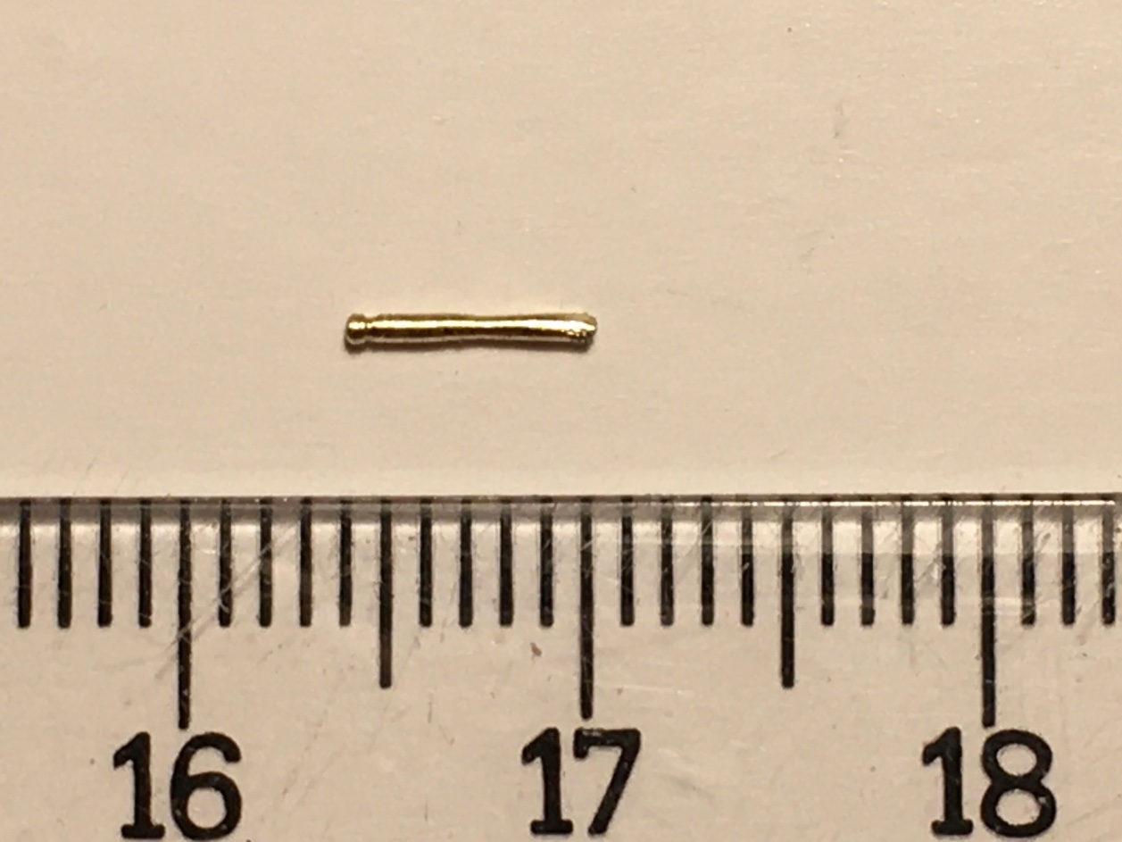
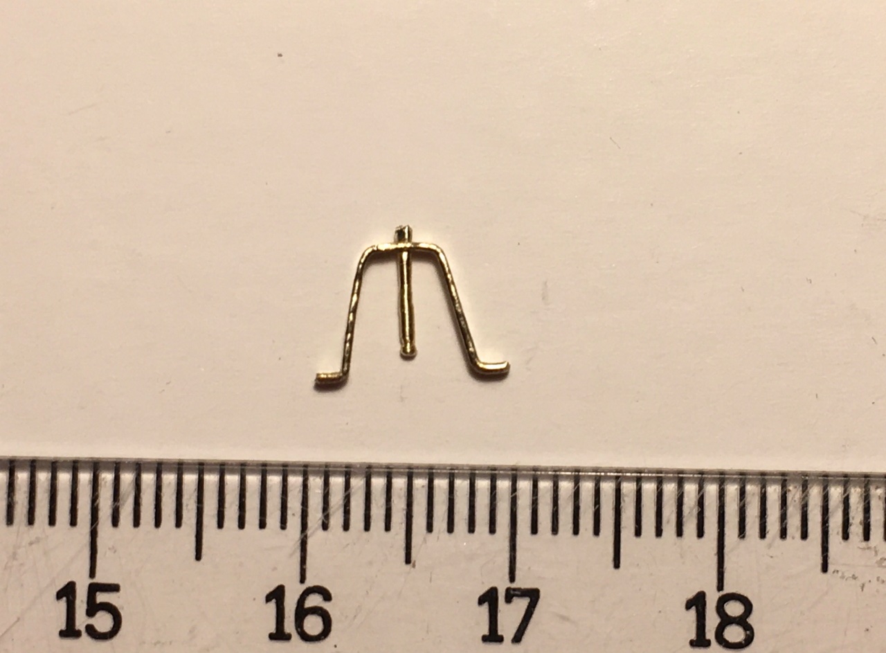
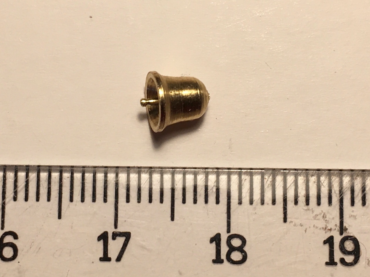
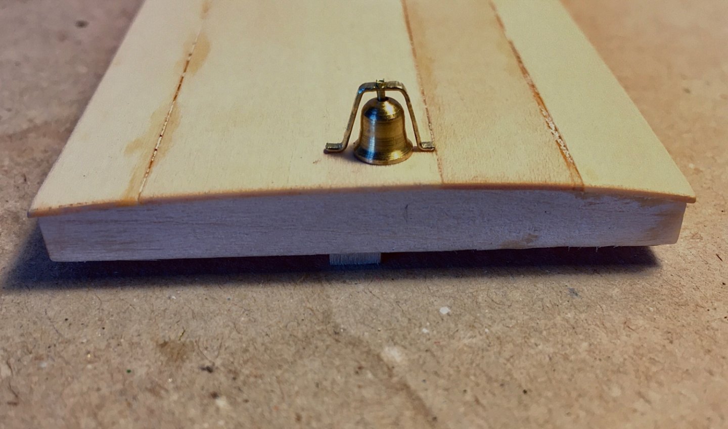
After cabin is the largest structure on the deck and it's roof harbors various structures. Just like the main salon top, first it's 4 side walls were put together. Then 4 piece top was placed leaving a space for the companionway. Sliding top of the companionway was manufactured just like the main salon's. Planked floor from 0.4 mm pear strips was made and put aside. As the windows of the structure at the fore end of the top were rectangular, they were easily cut out from a previous project's plexiglass parts. The window frames were inserted and sanded leaving a small elevation. I did not attempt to manufacture those windows with movable hinges . The small window on the starboard side of the top was also made from plexiglass. However it's frame was manufactured from a suitable brass sheet. The small vent was made from brass rod by turning it with Dremel 8200 mounted at Dremel work station. Ship's bell and it's holding frame from brass strip was also put a side after manufacturing and dry fitting. Roof planking was also made as three pieces, just like the main salon, along with the mahogany side planks. The side planks were placed first followed by the three inside pieces. After staining, painting and matt final coats the cabin top was put aside with all the other top structures to be glued in a later stage. The kit's bell was damaged when shaping it. The Modelexpo Co mailed another one but that one was also damaged during transport. I purchased brass ones from Constructo Models and manufactured a new system. Vent at the middle of the roof was manufactured from brass rod by turning it with Dremel 4000. Finished after cabin photos The masks on the windows were kept in place until the structures final installment time.


- 114 replies
-
- 3
-
-
- Pride of Baltimore II
- Model Shipways
- (and 1 more)