halituzun
-
Posts
137 -
Joined
-
Last visited
Content Type
Profiles
Forums
Gallery
Events
Everything posted by halituzun
-
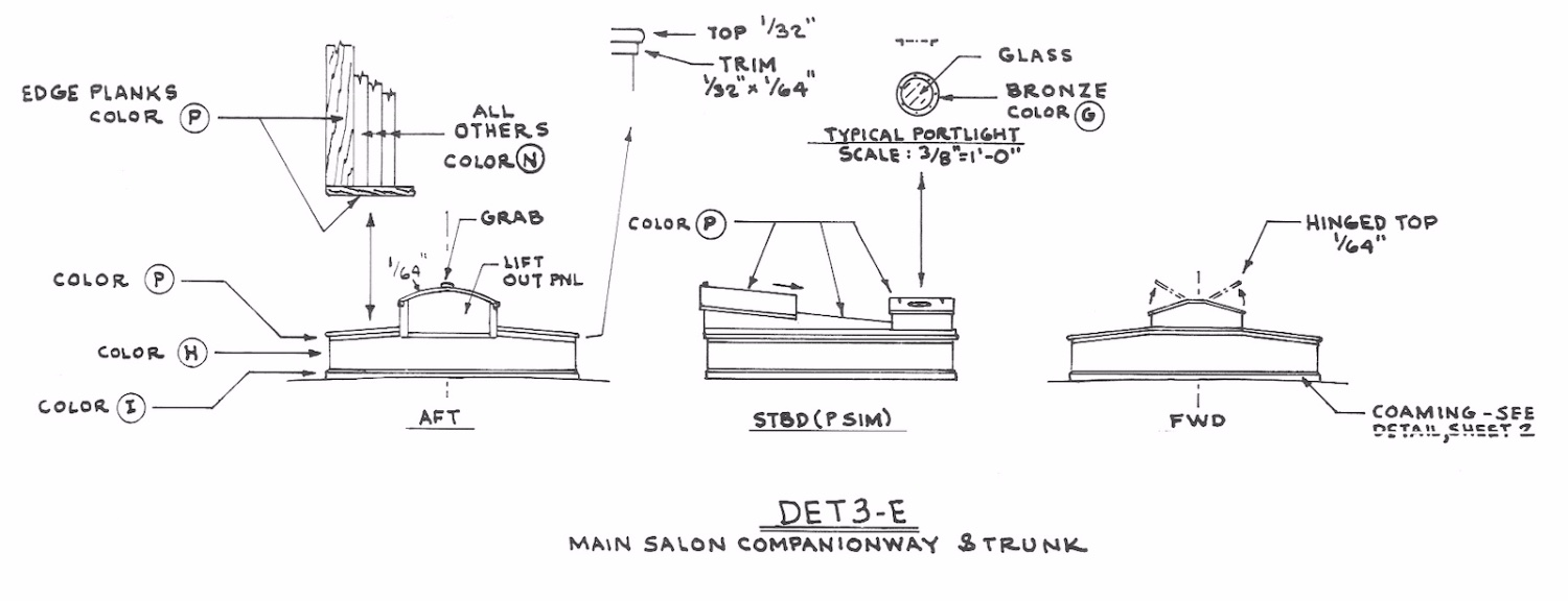
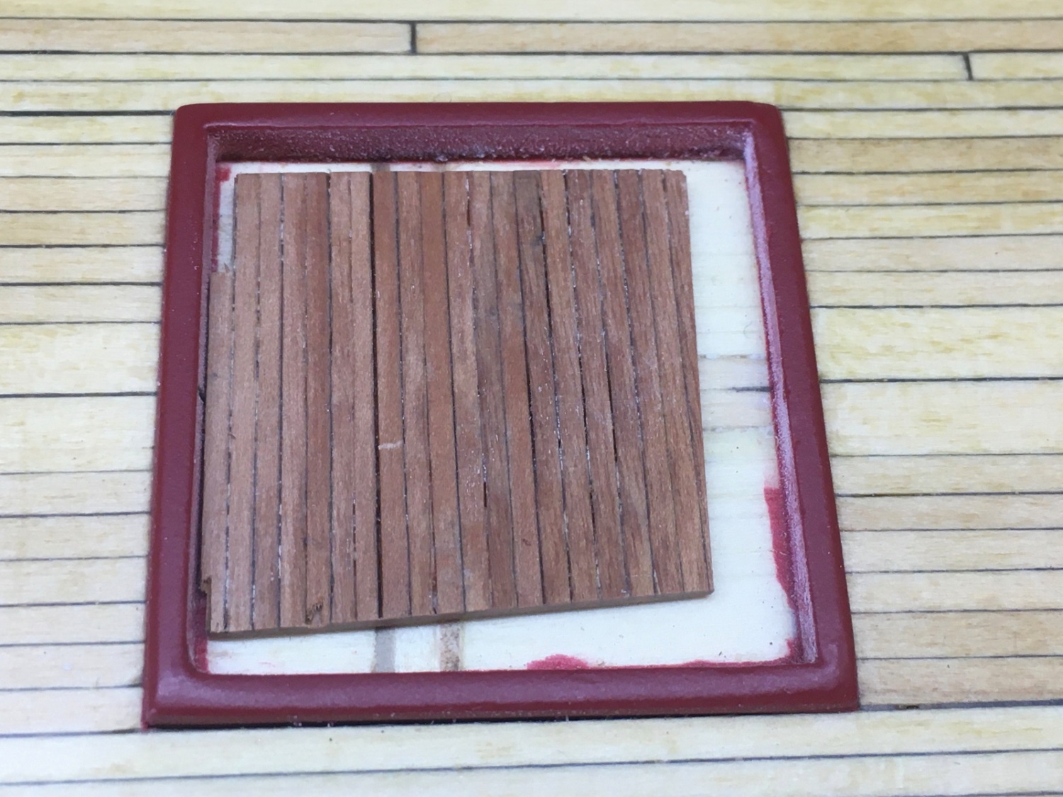
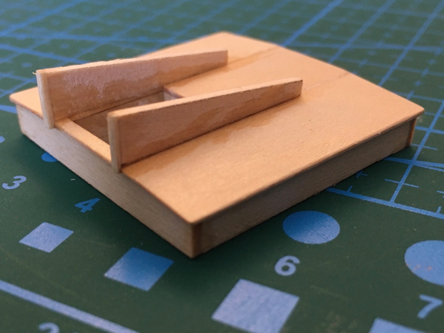
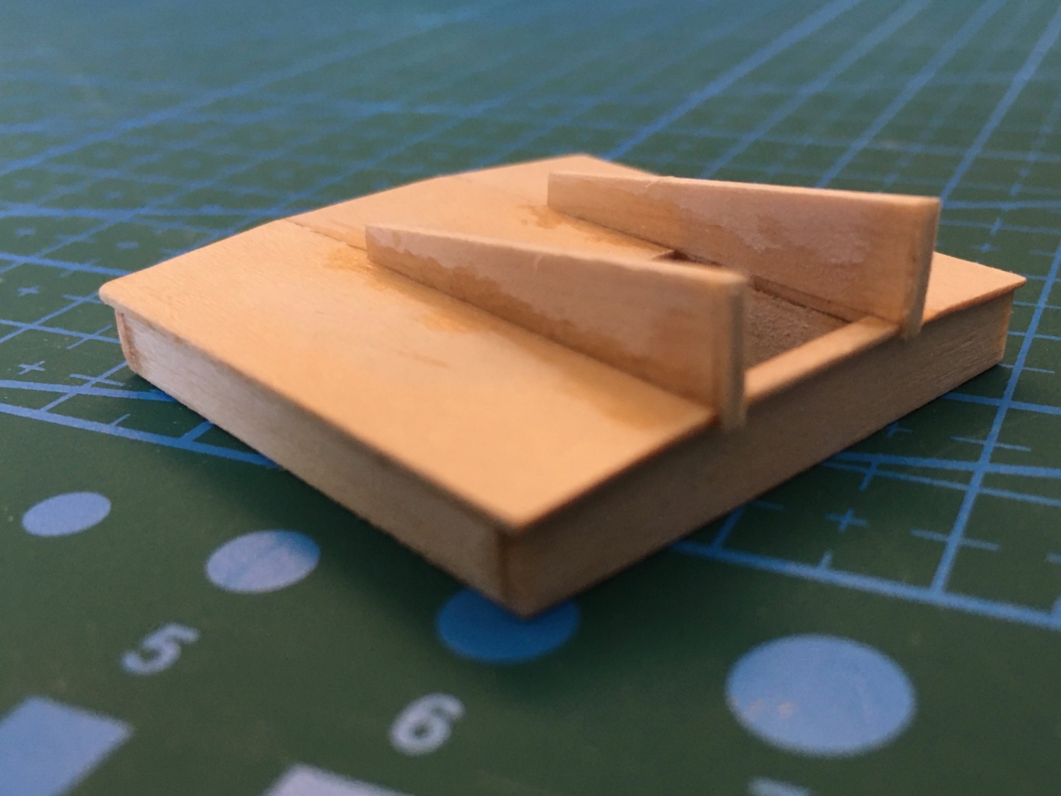
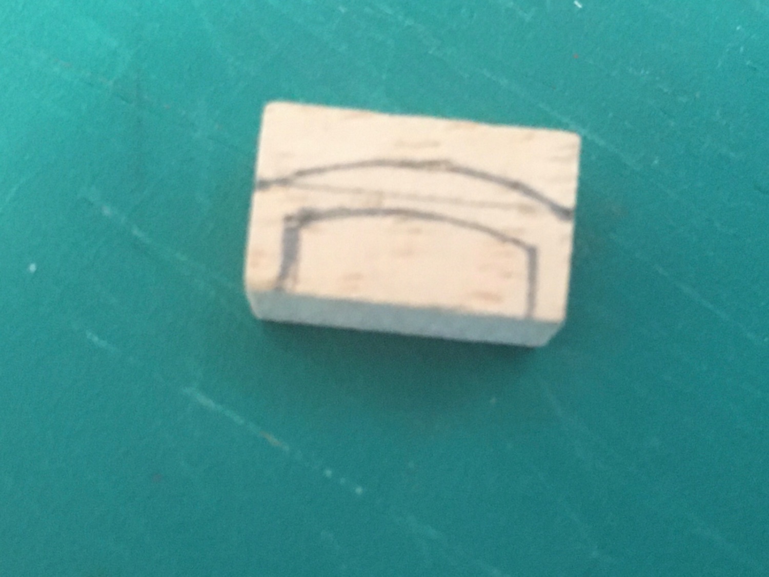
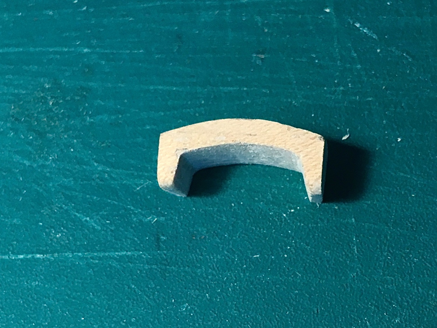
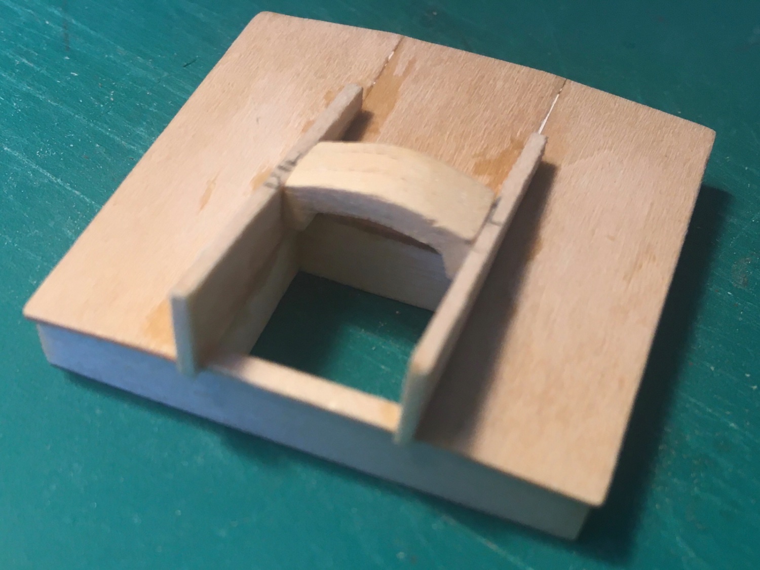
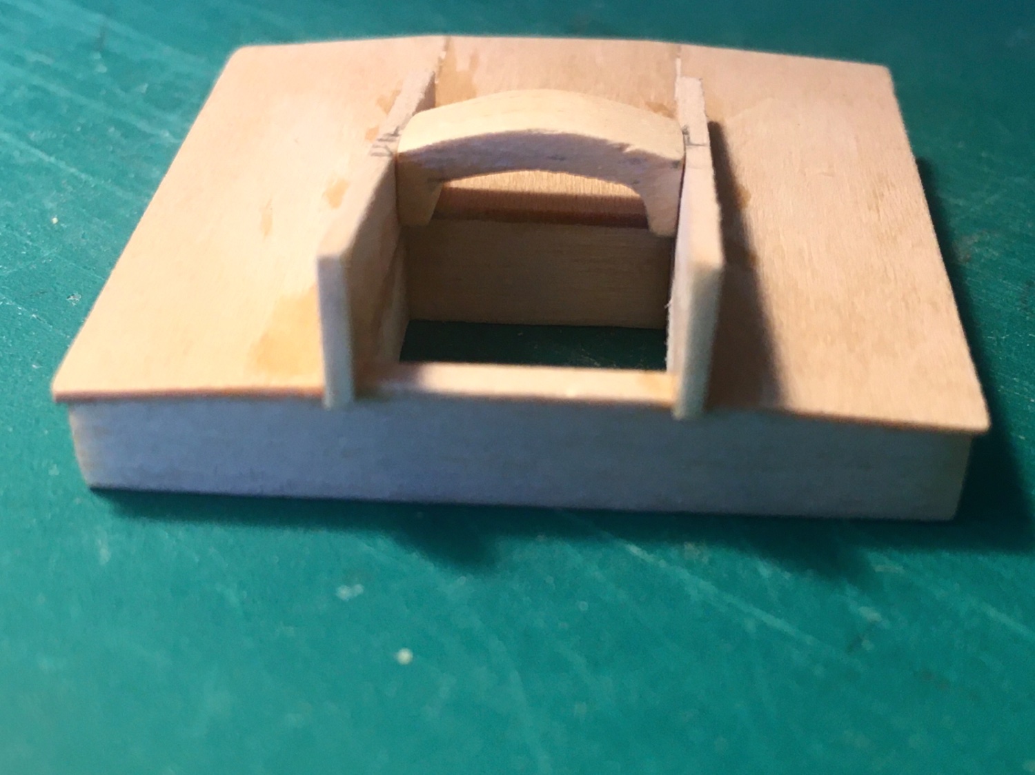
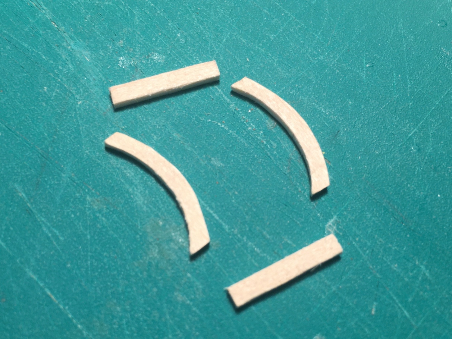
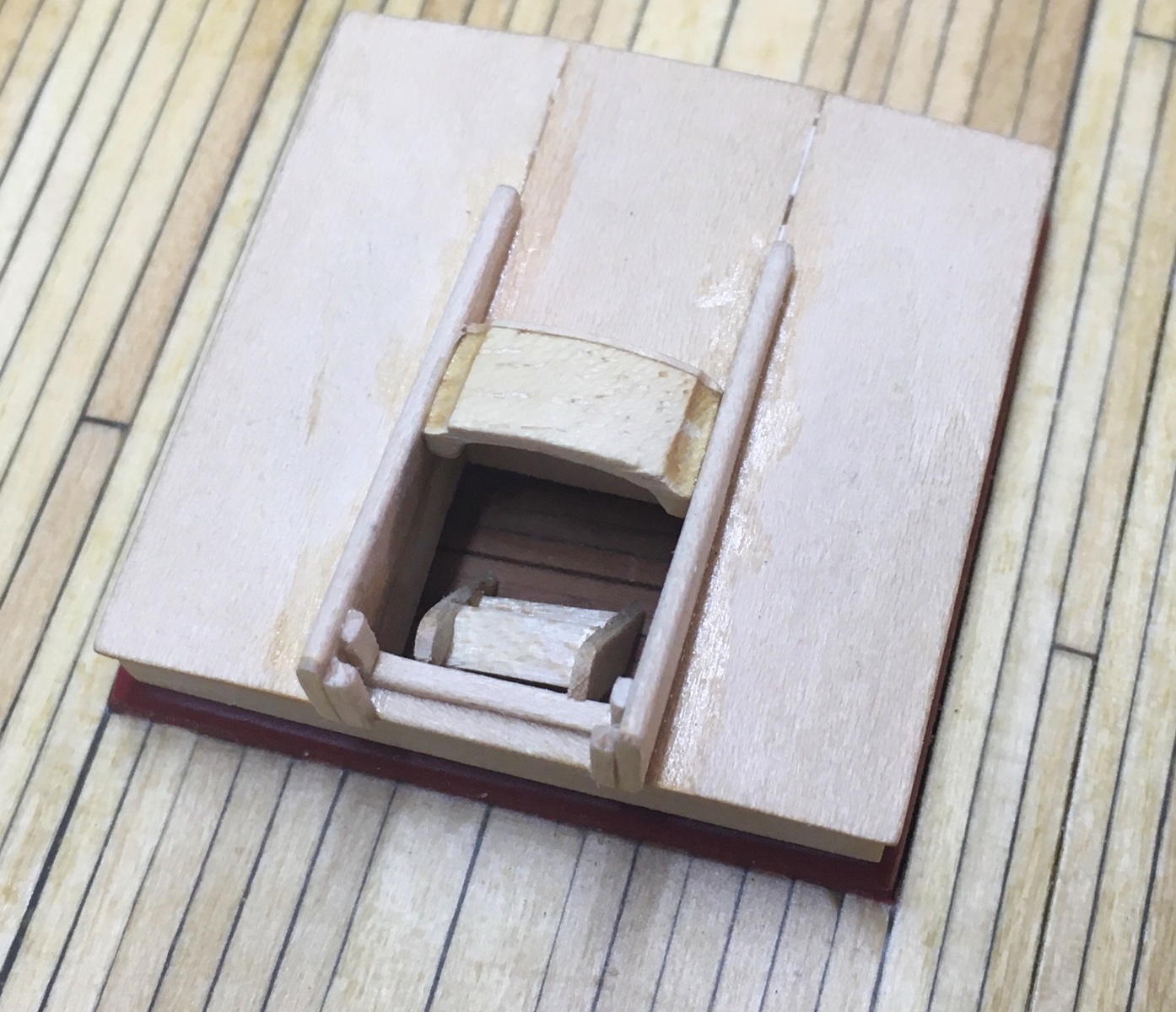
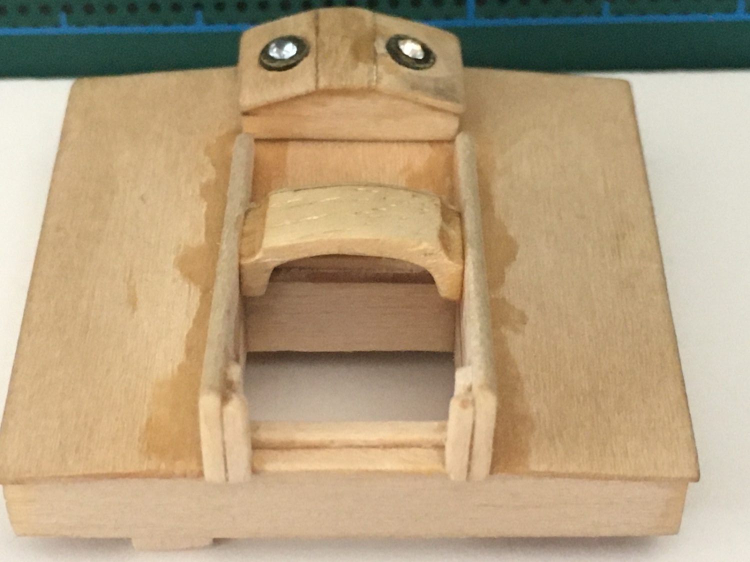
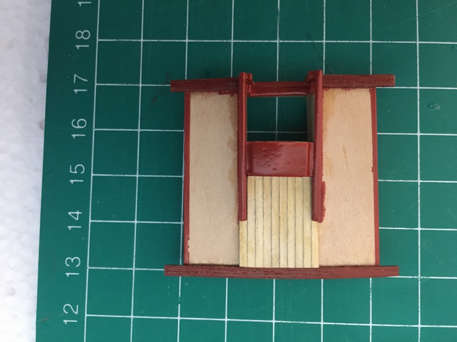
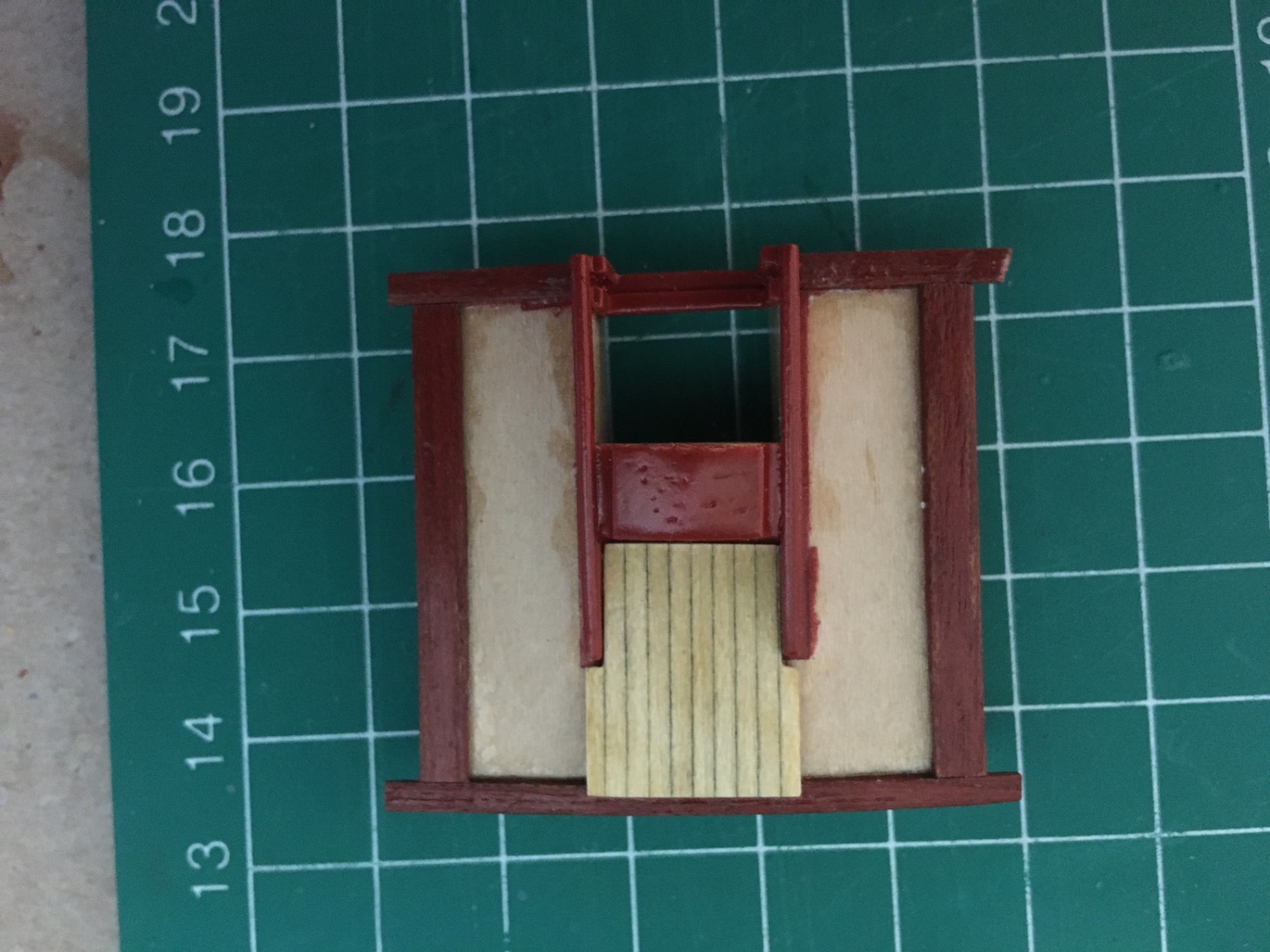
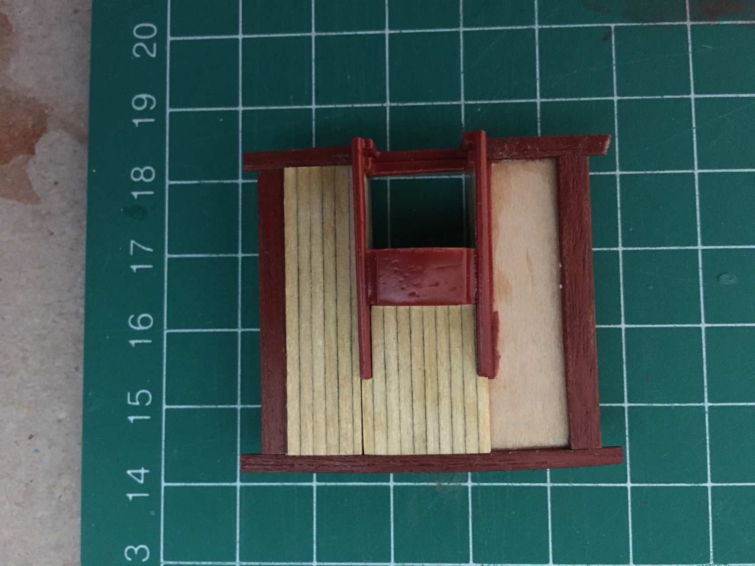
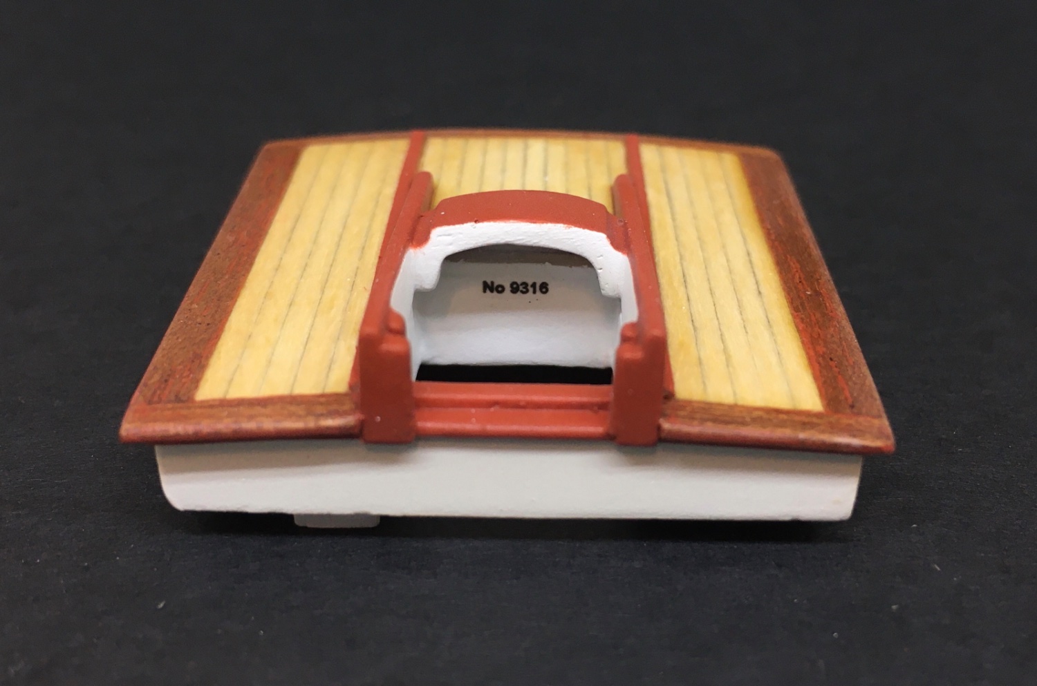
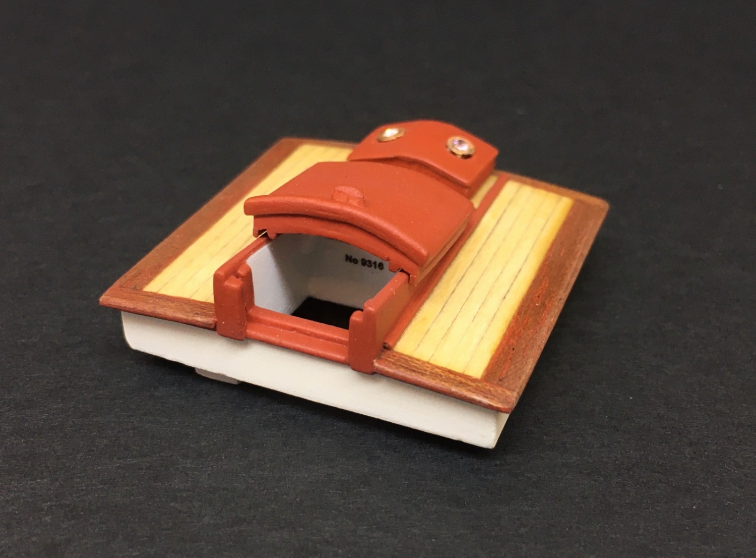
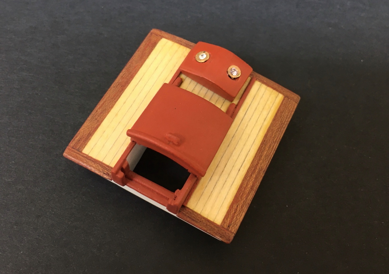
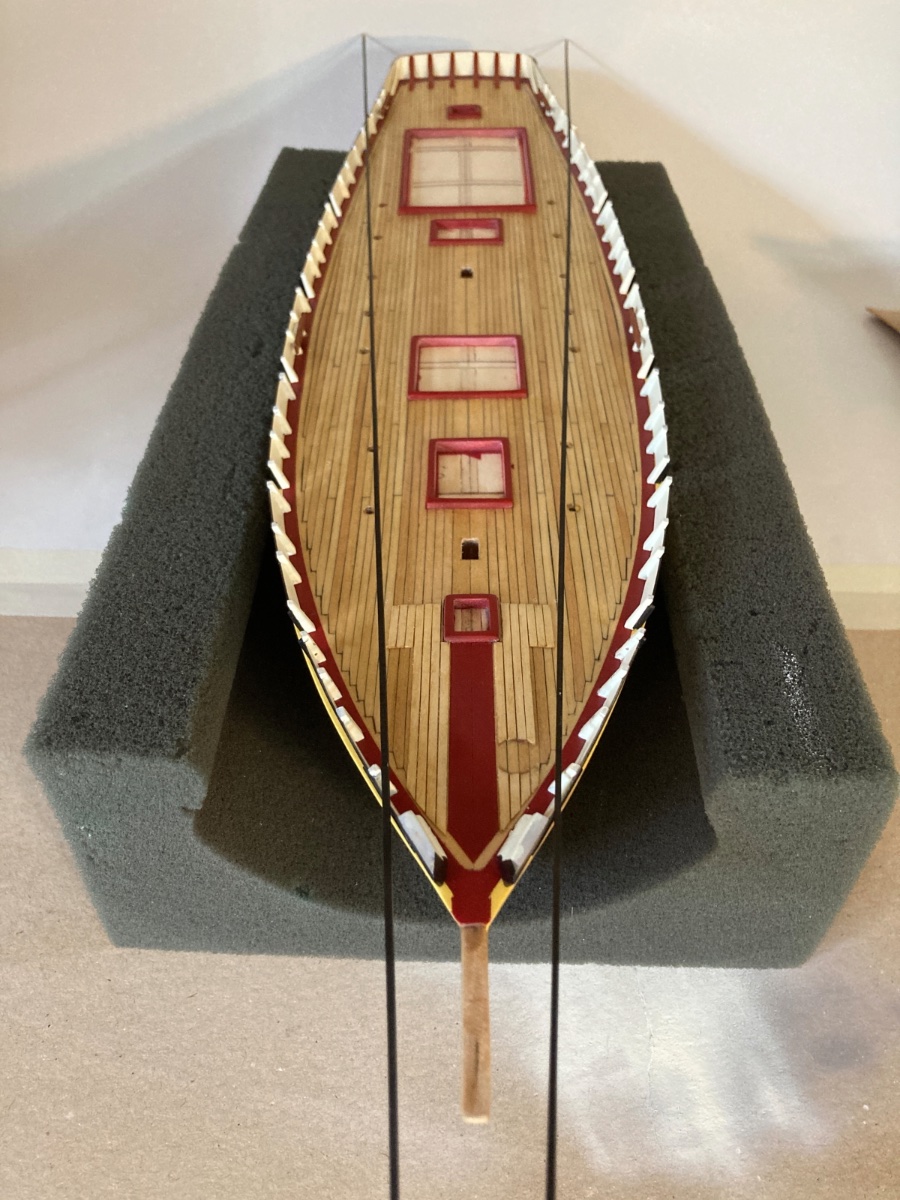
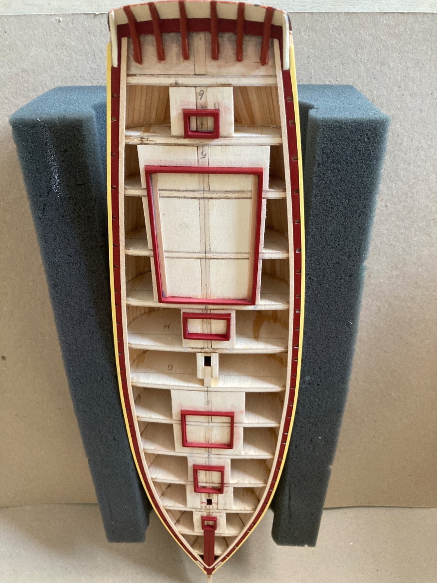
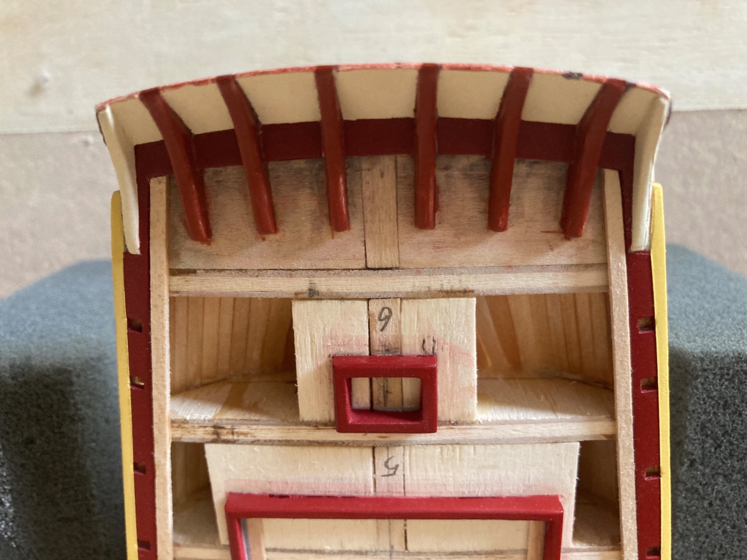
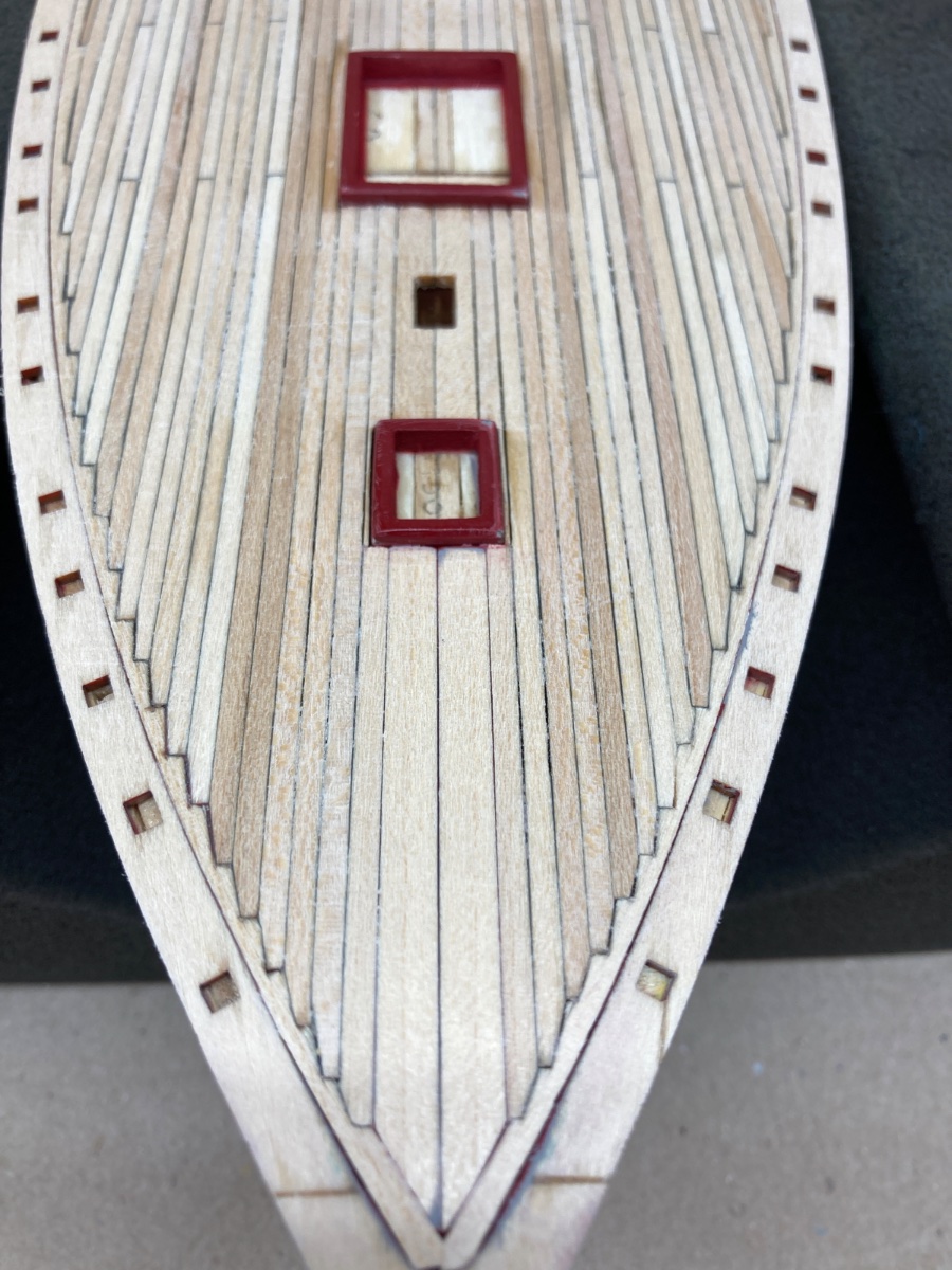
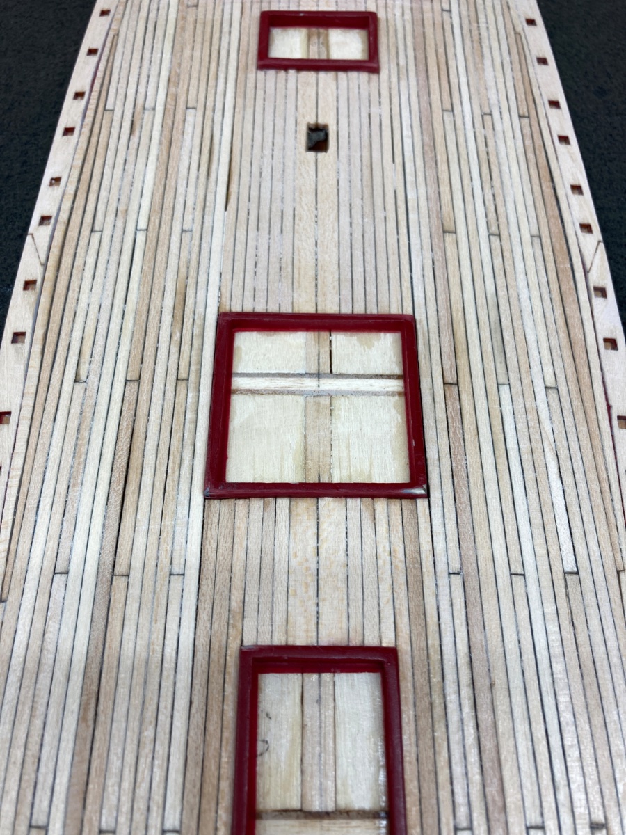
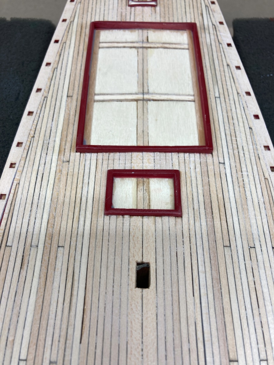
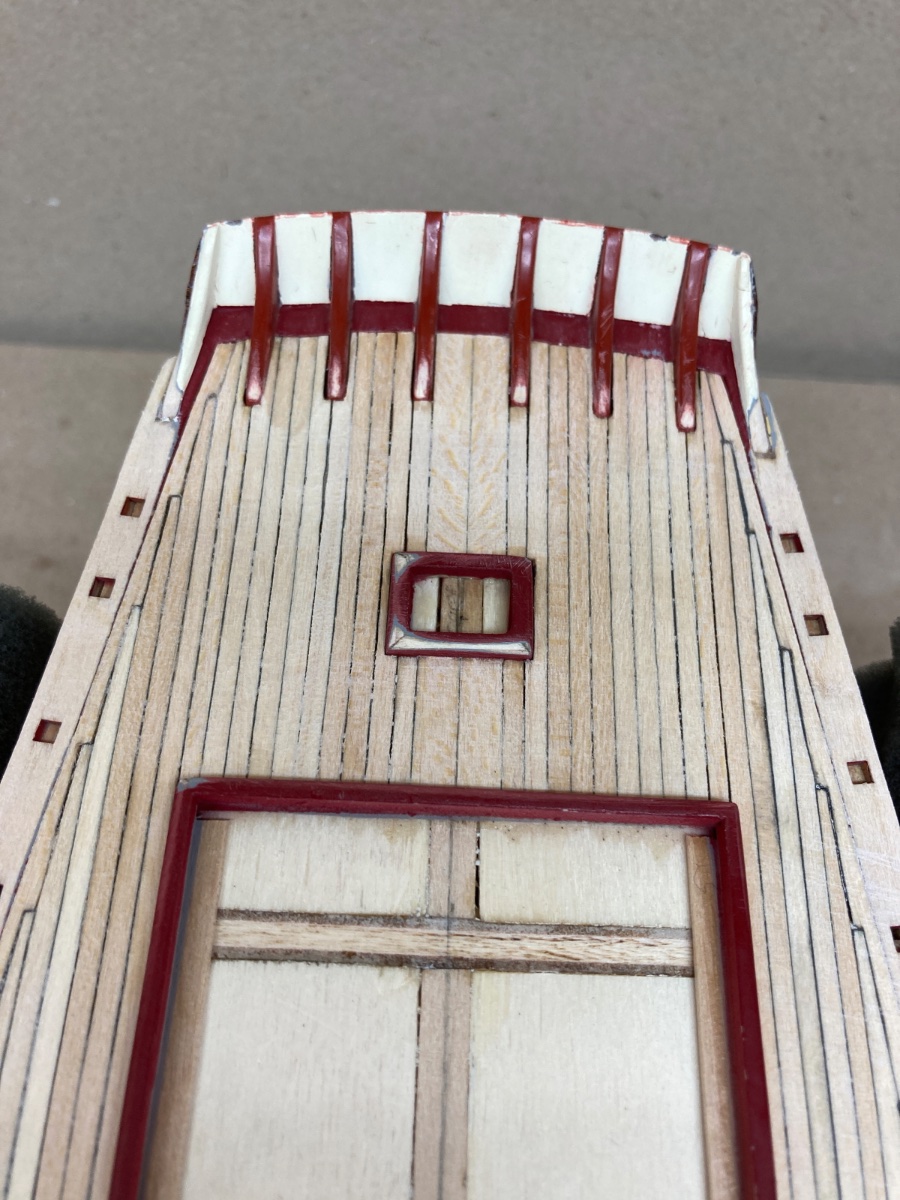
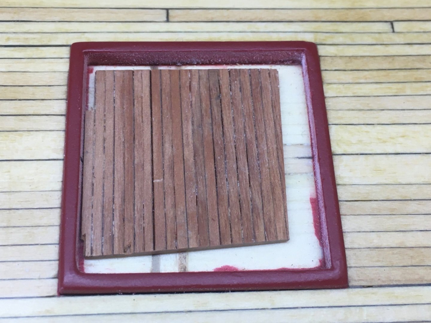
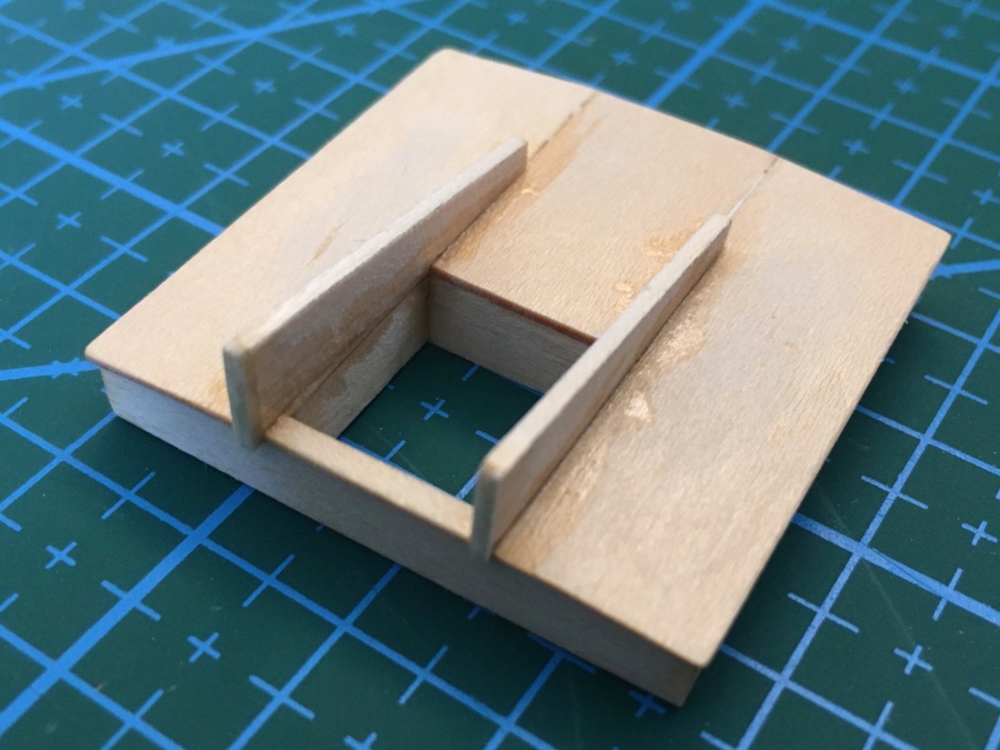
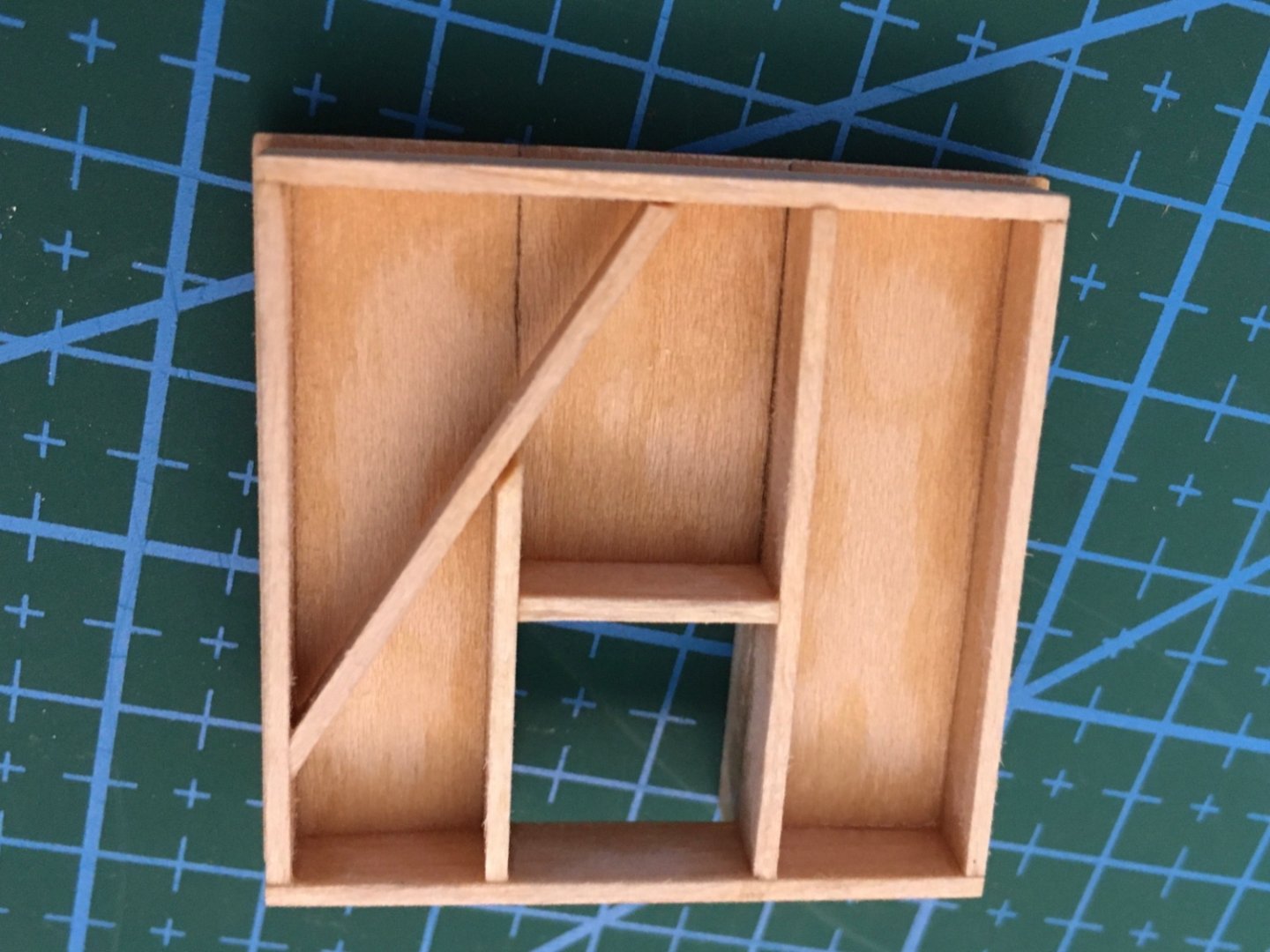
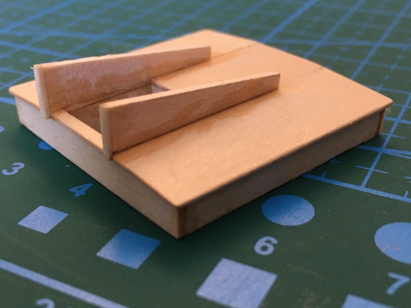
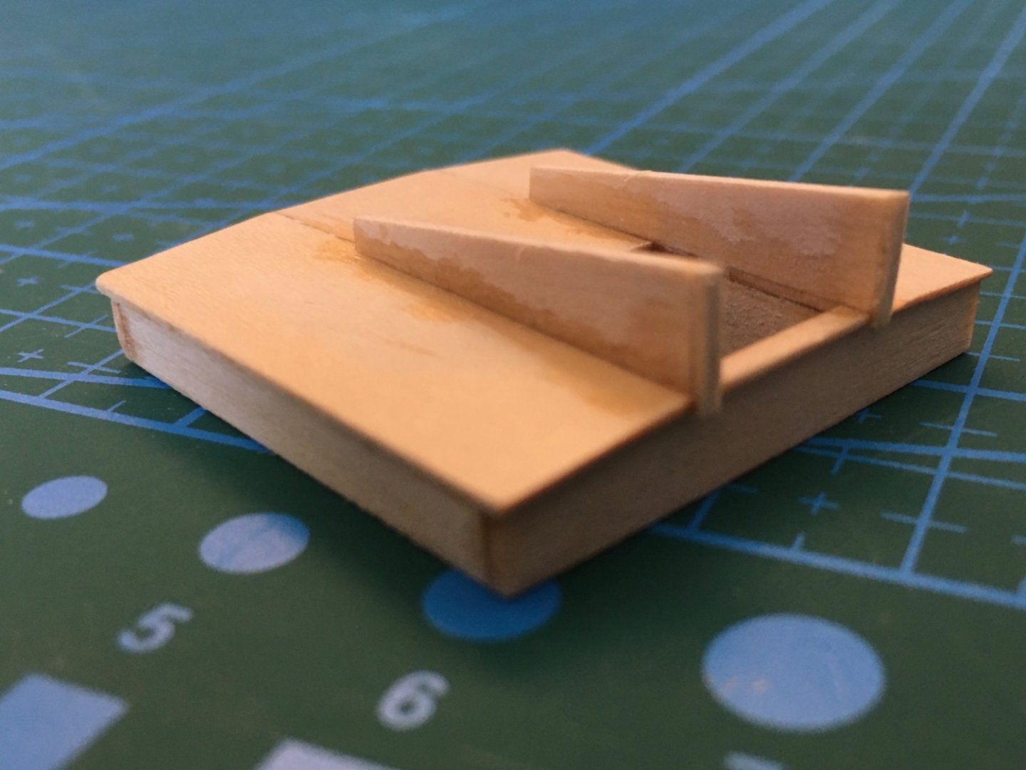
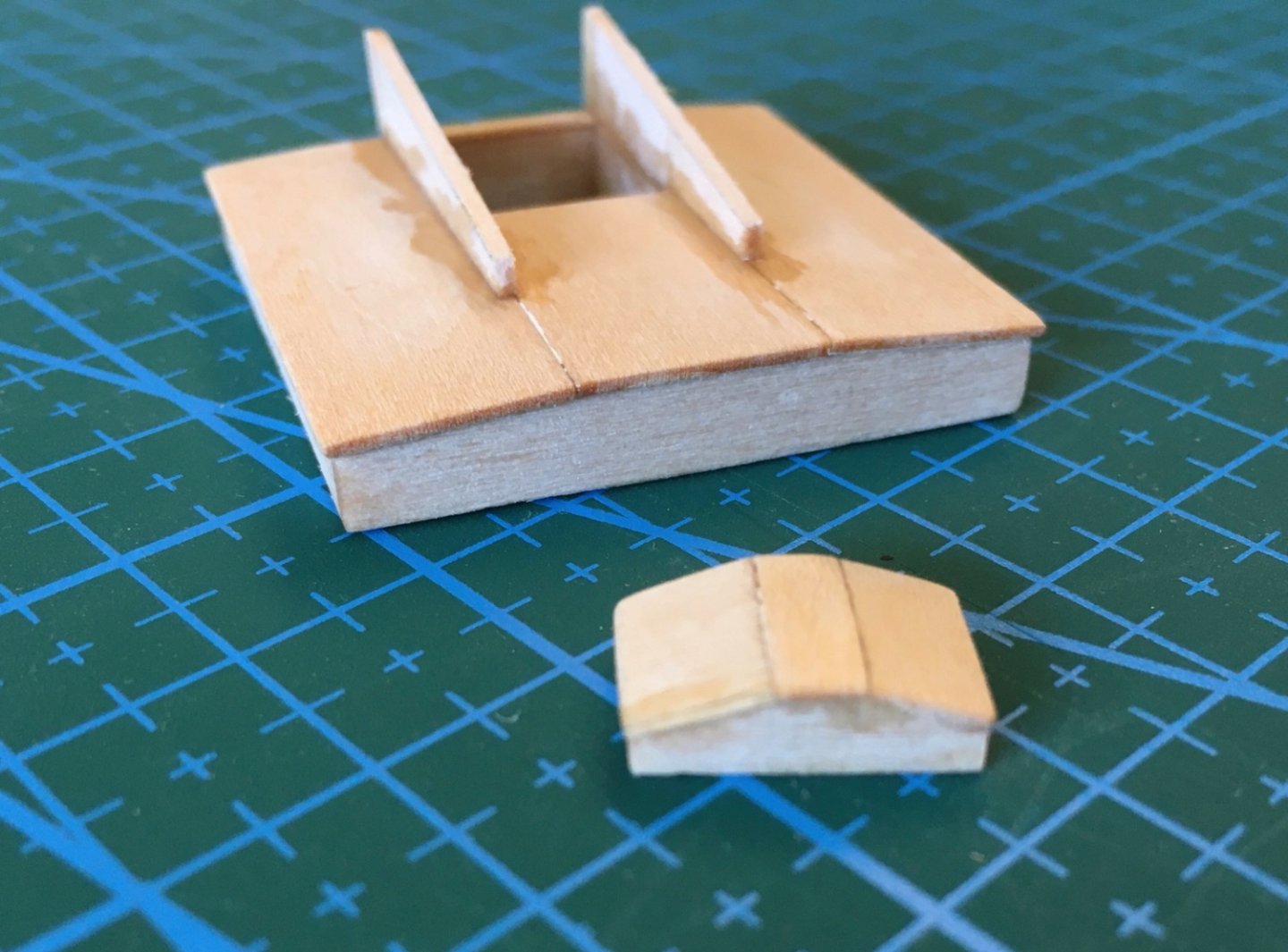
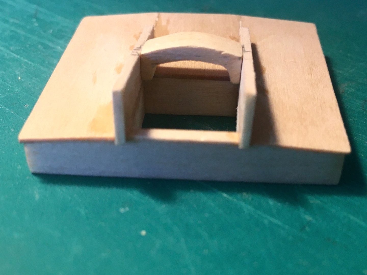
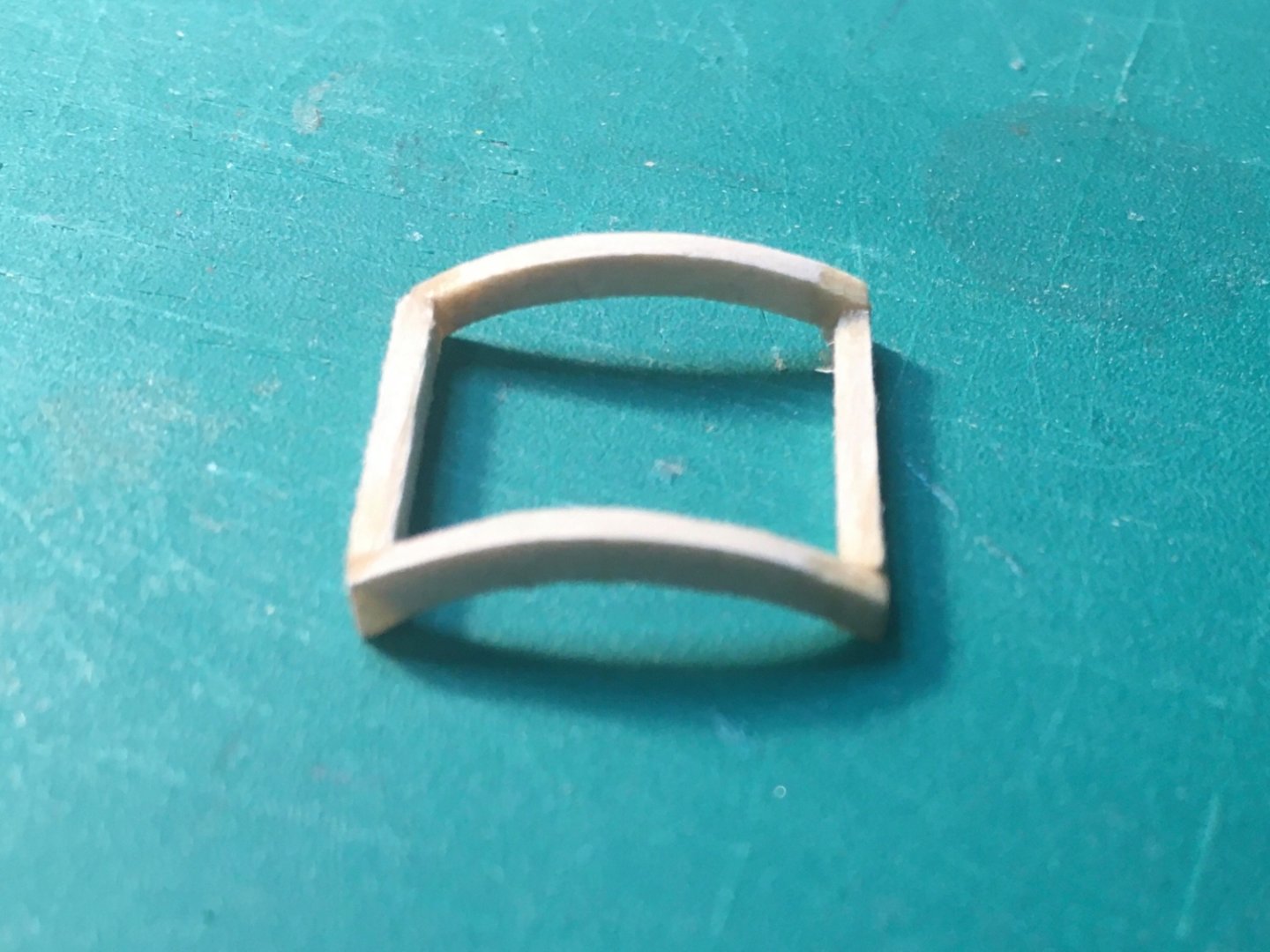
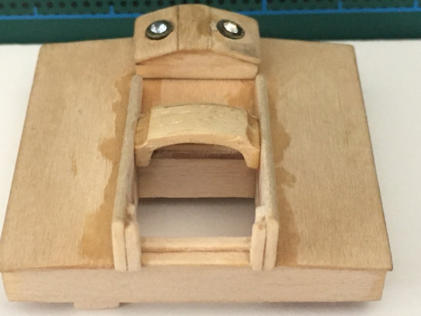
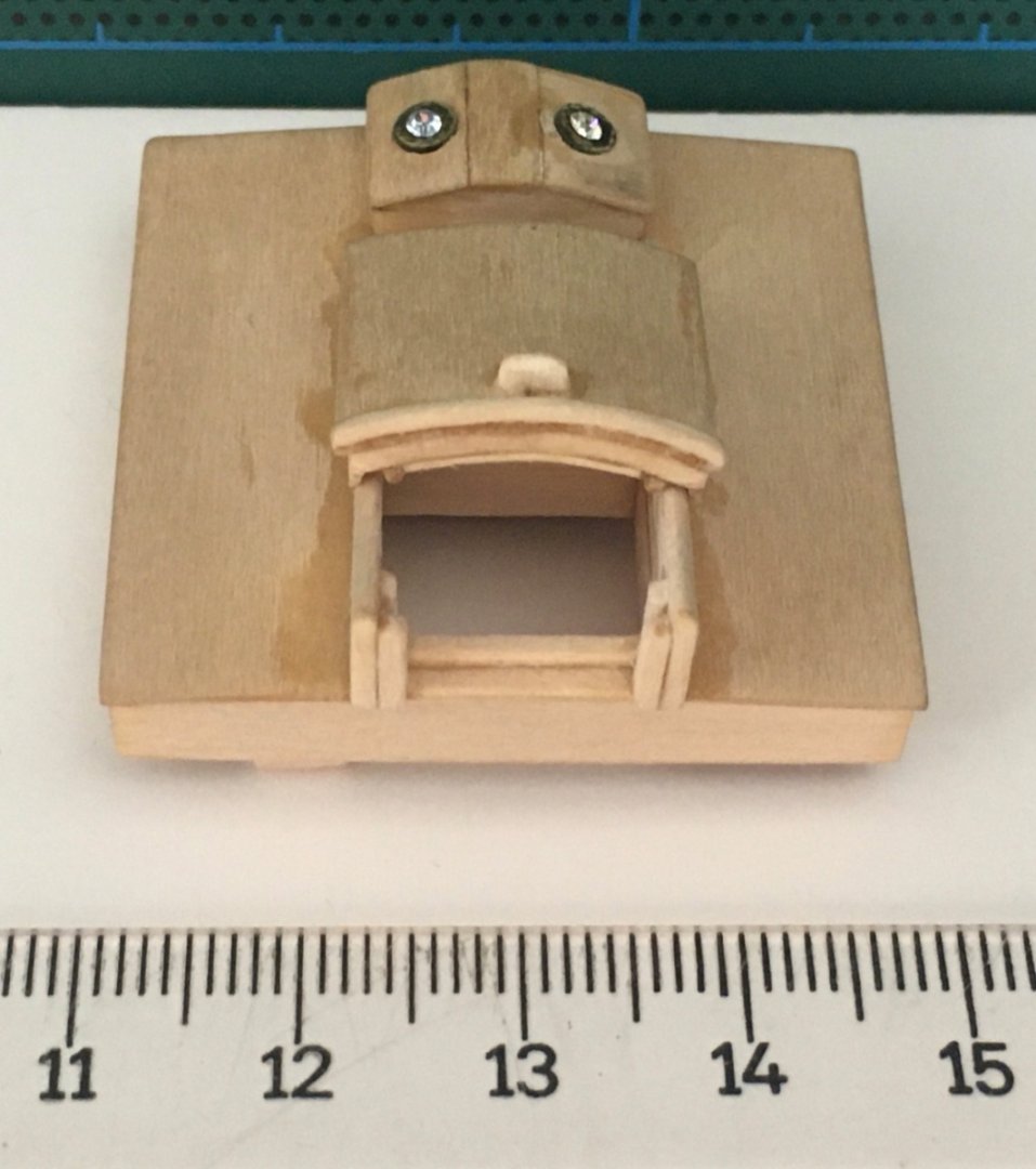
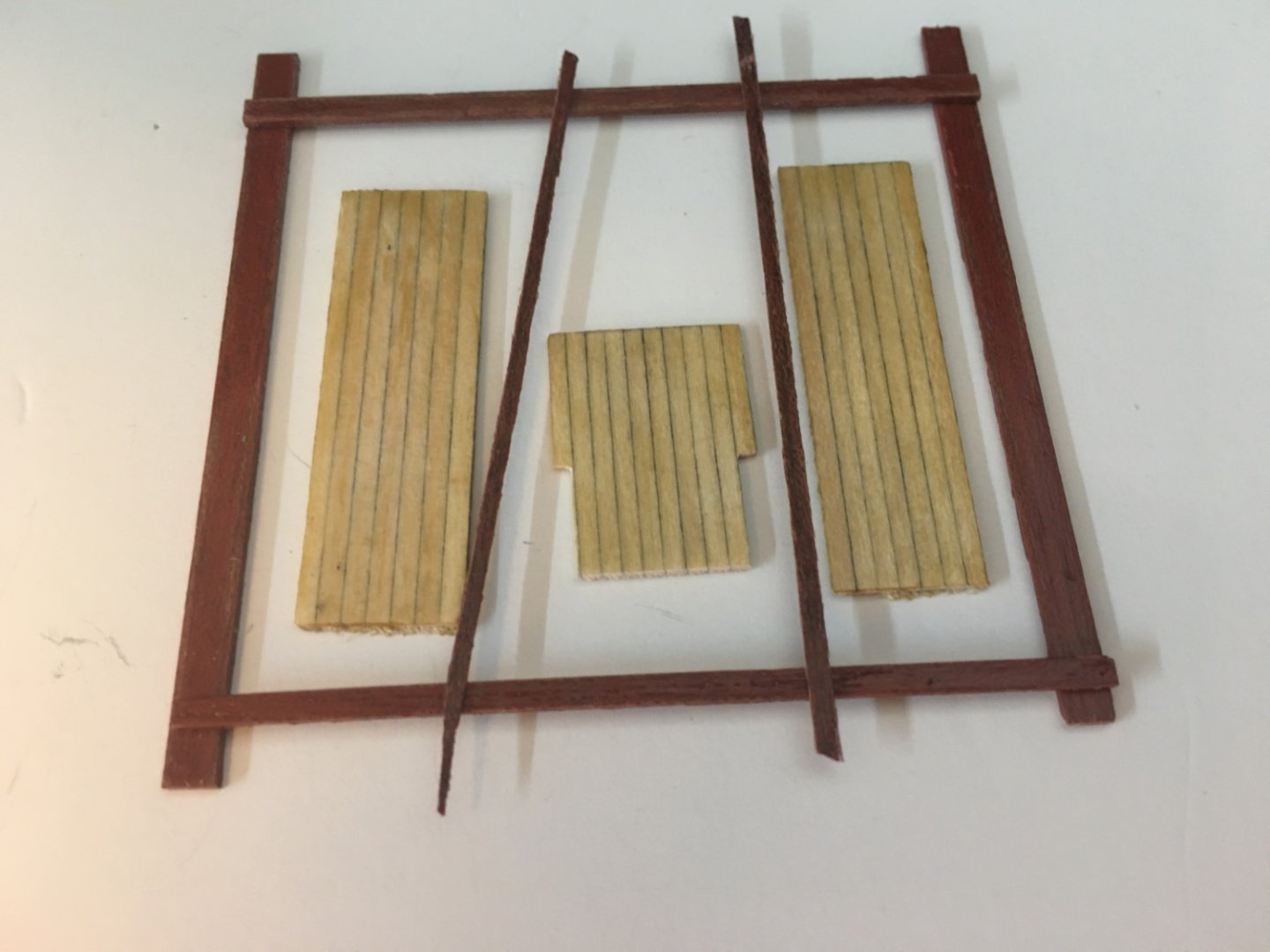
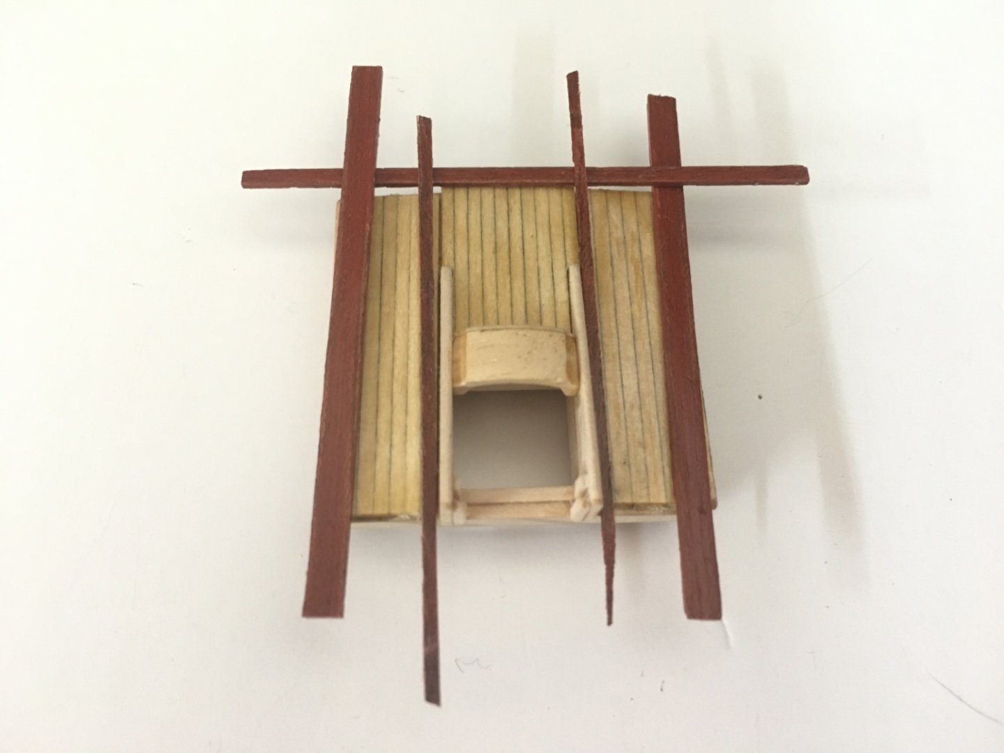
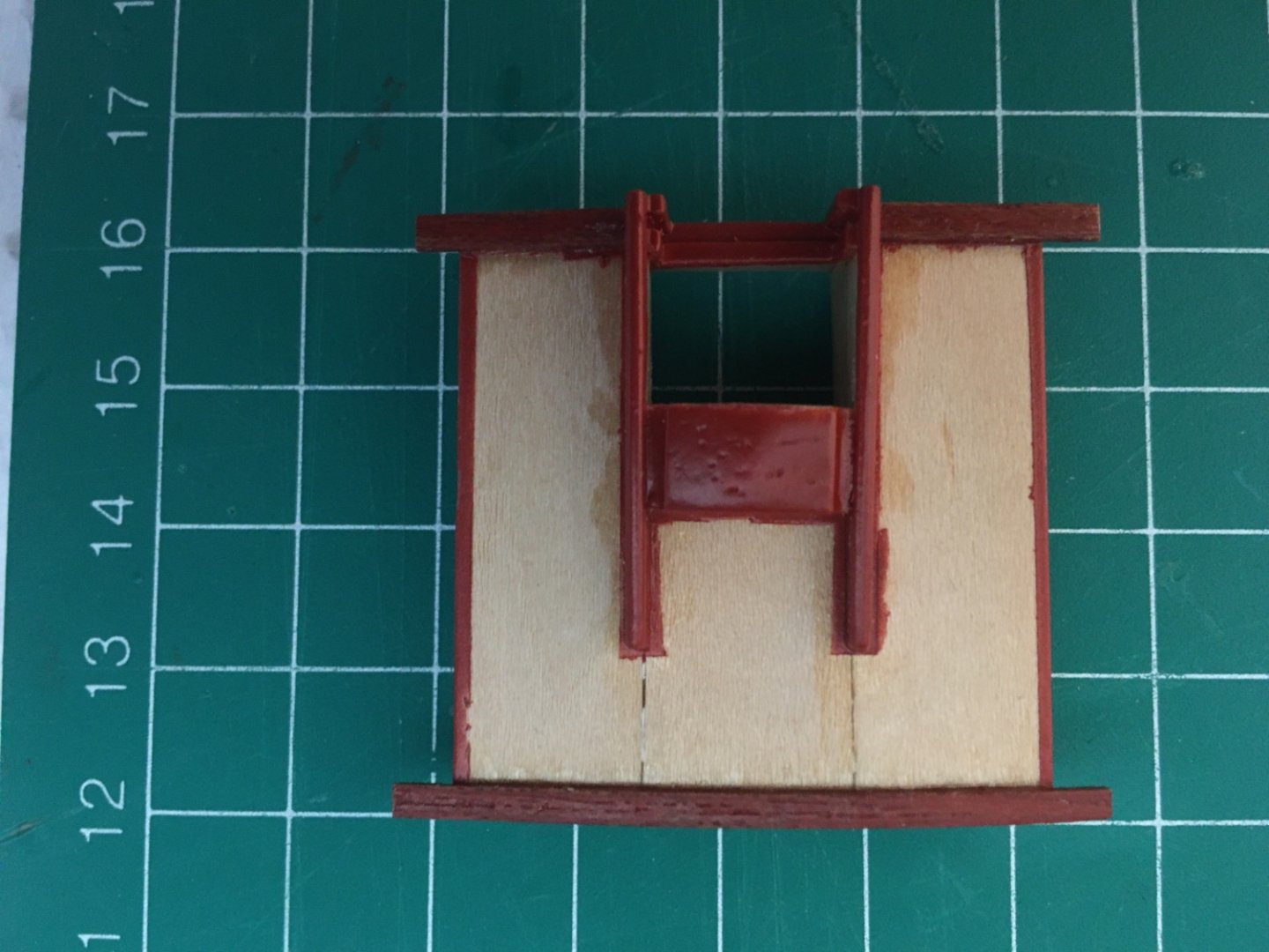
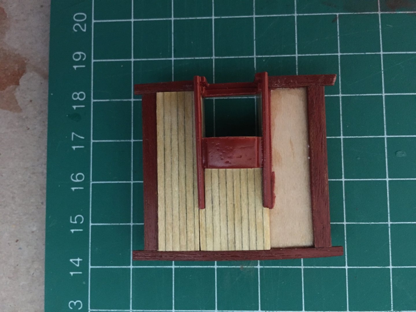
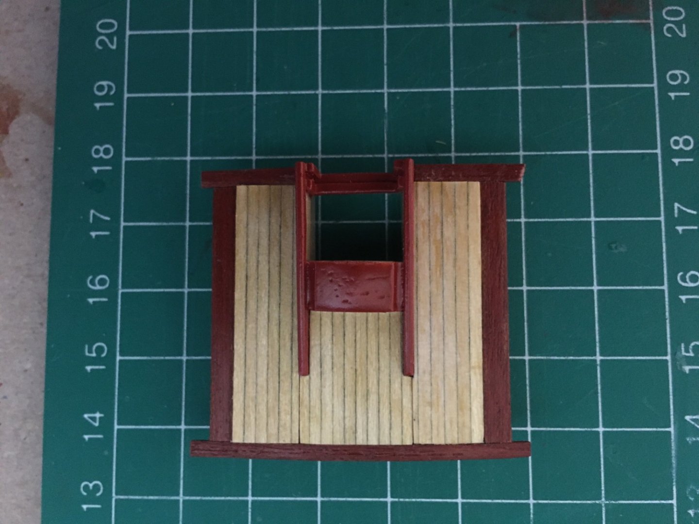
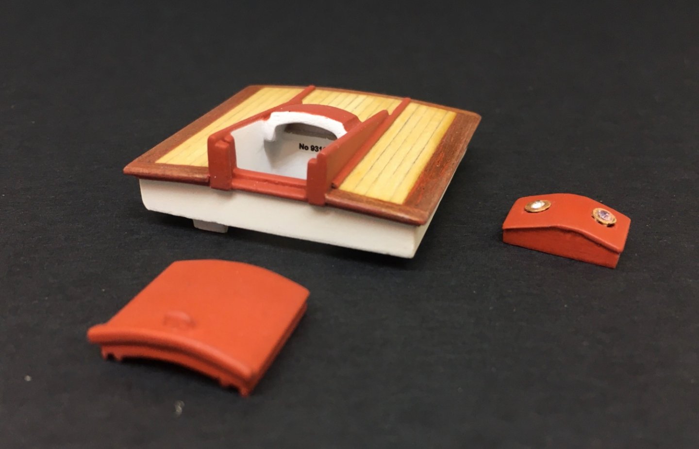
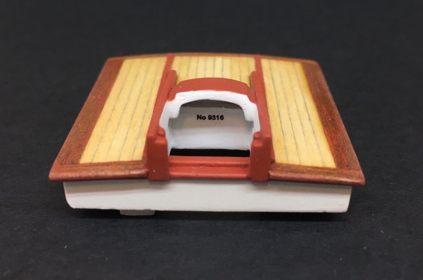
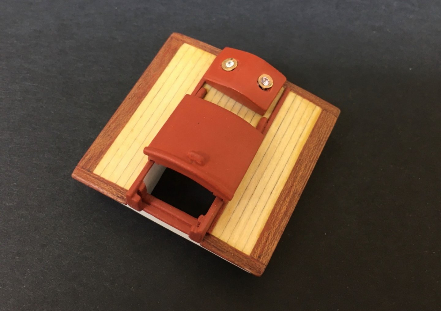
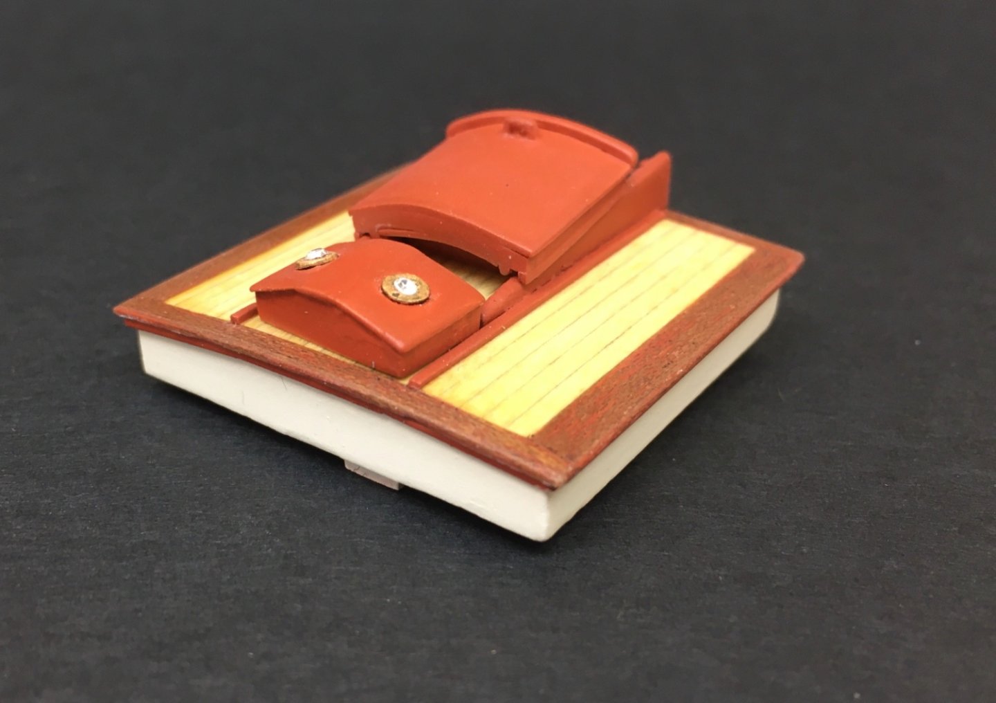
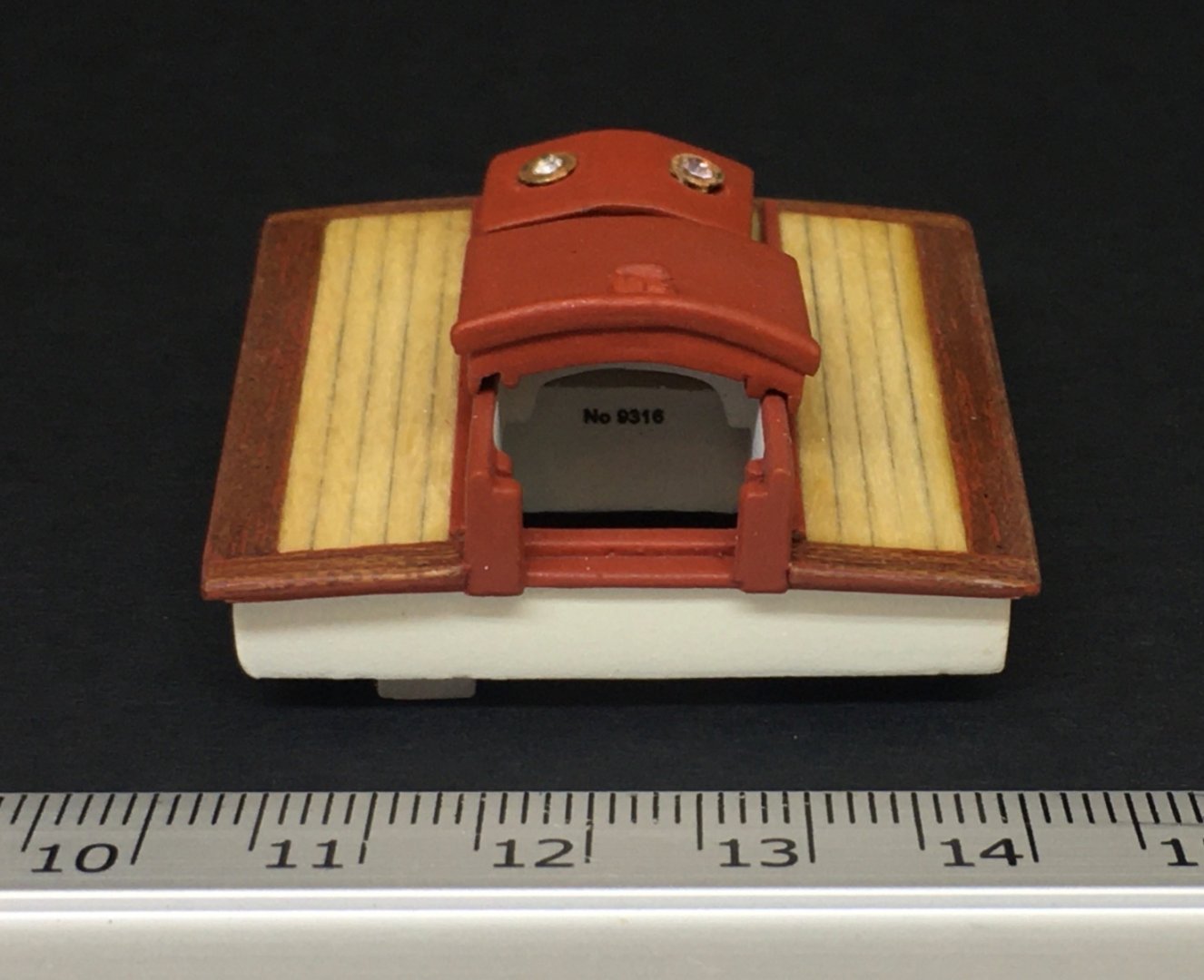
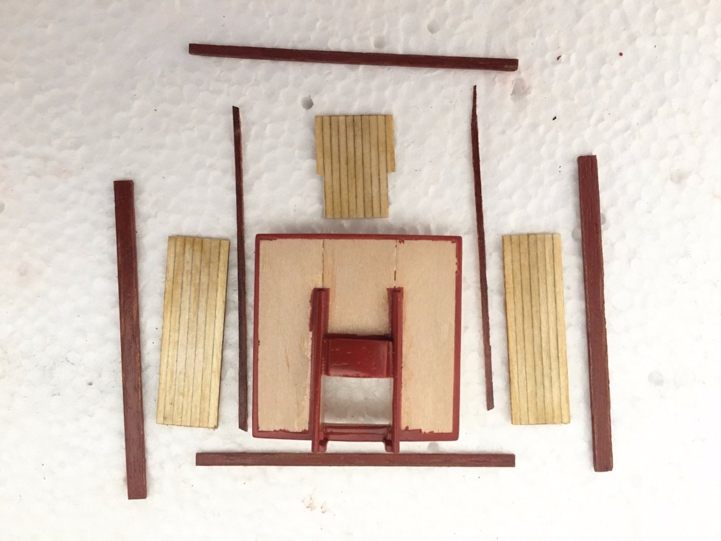
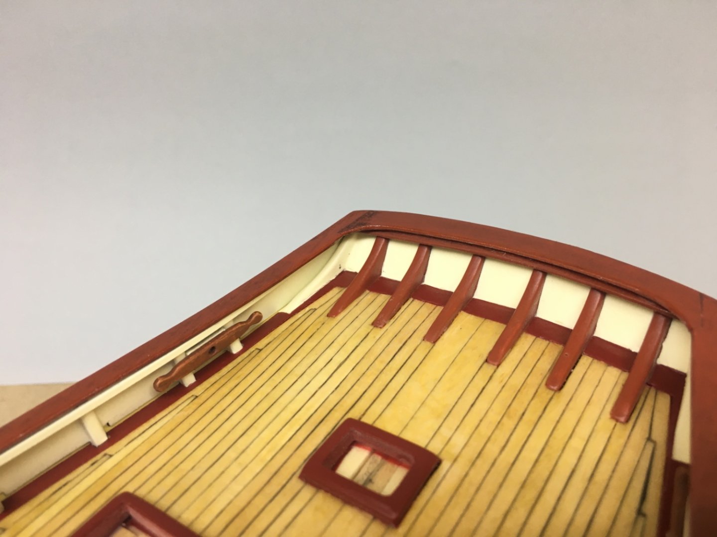
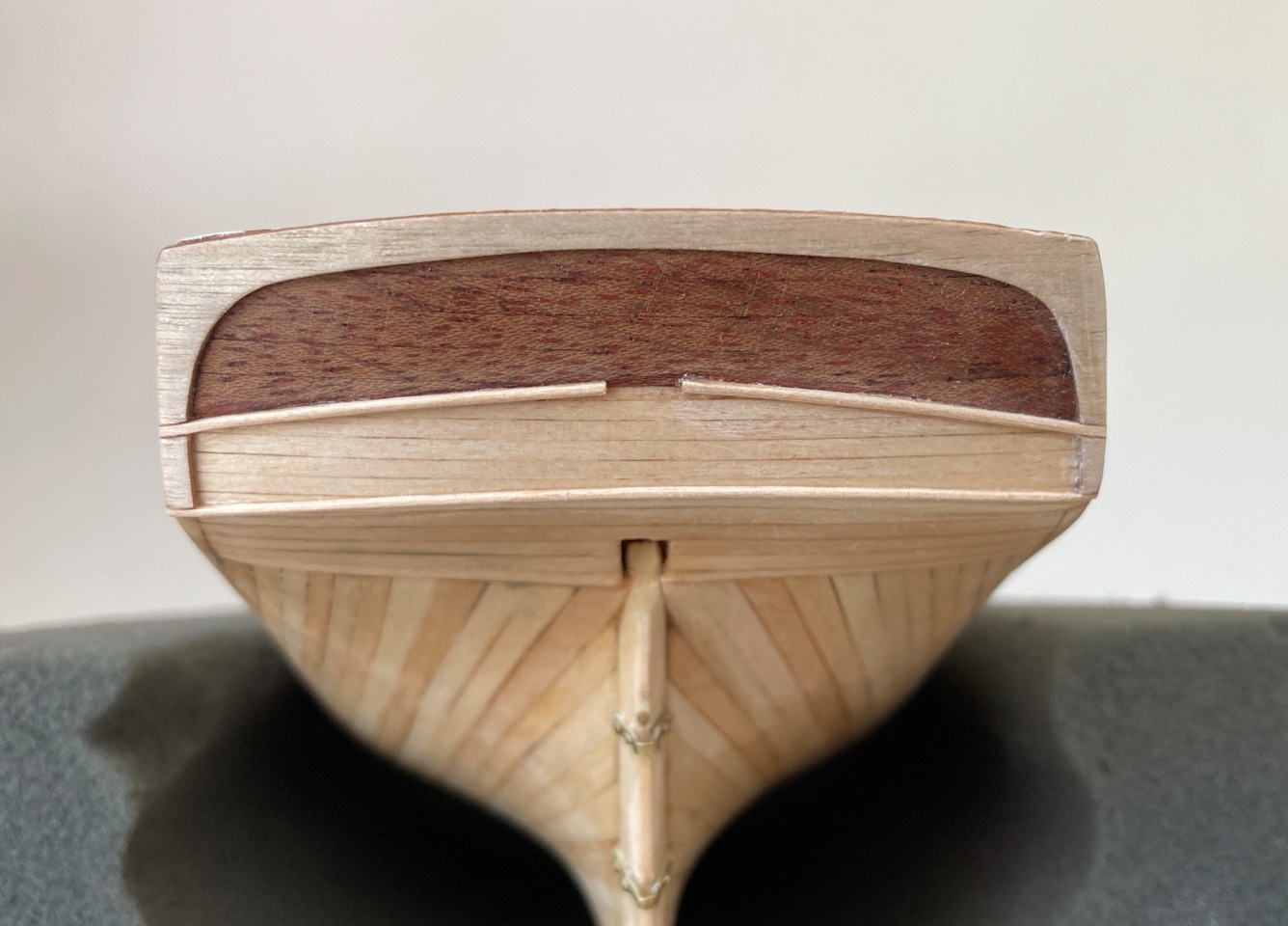
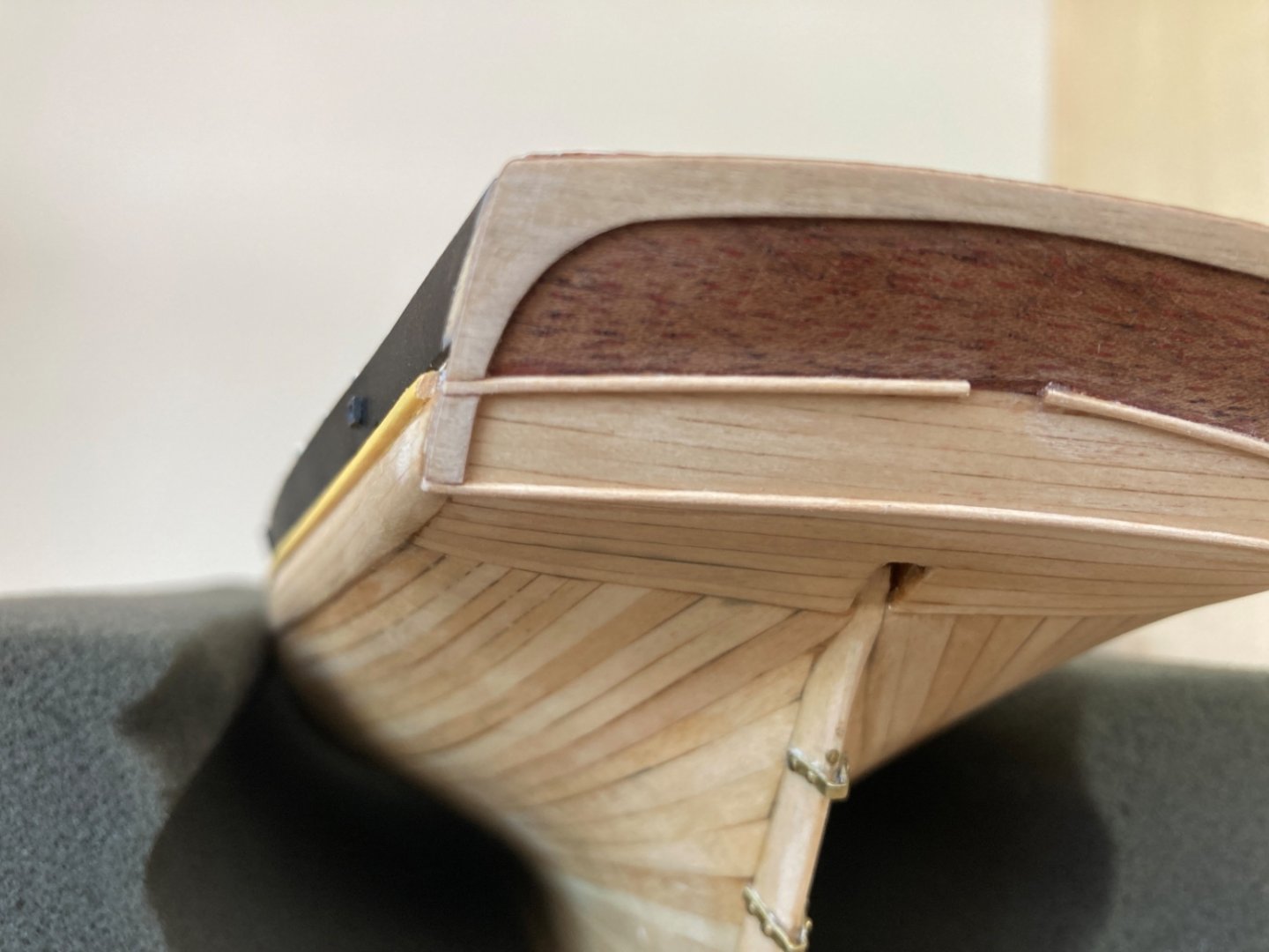
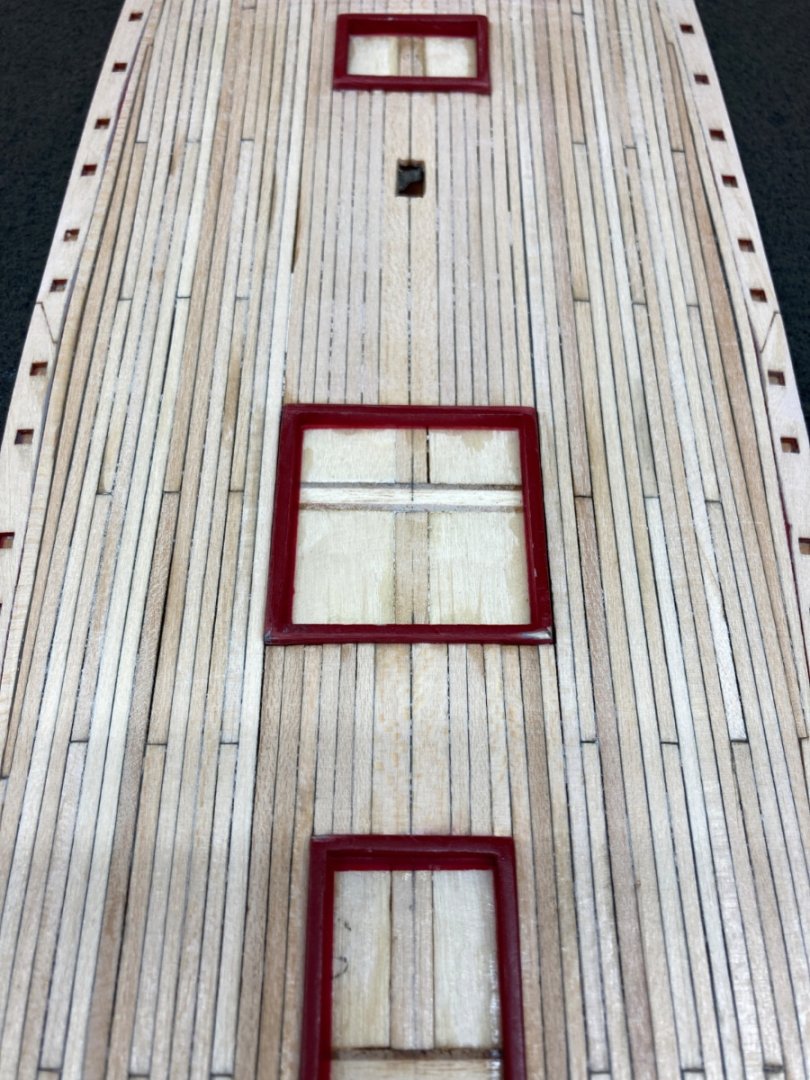
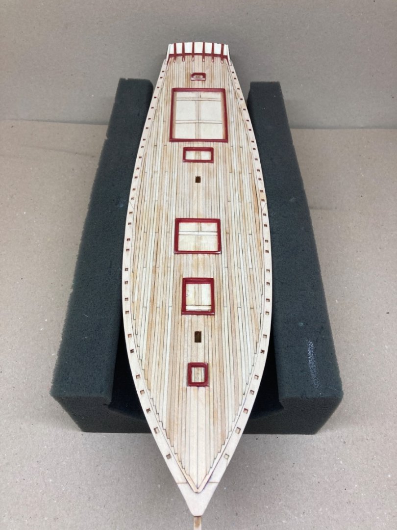
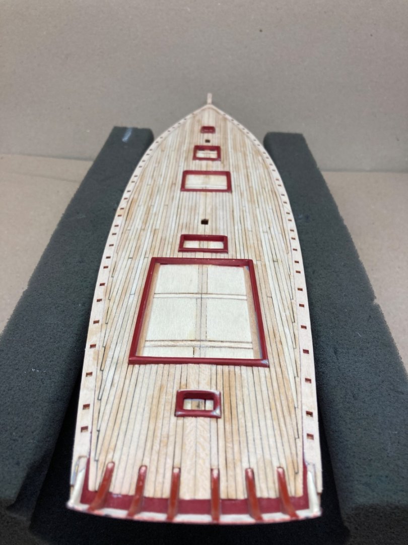
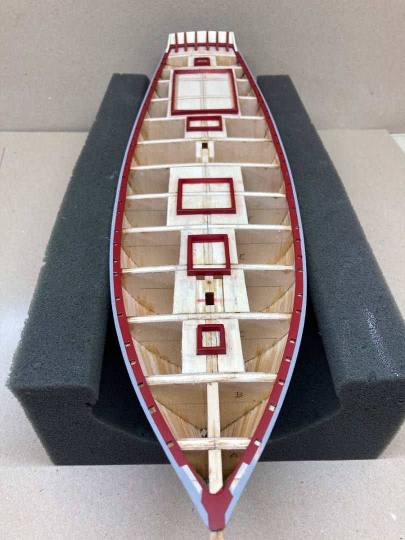
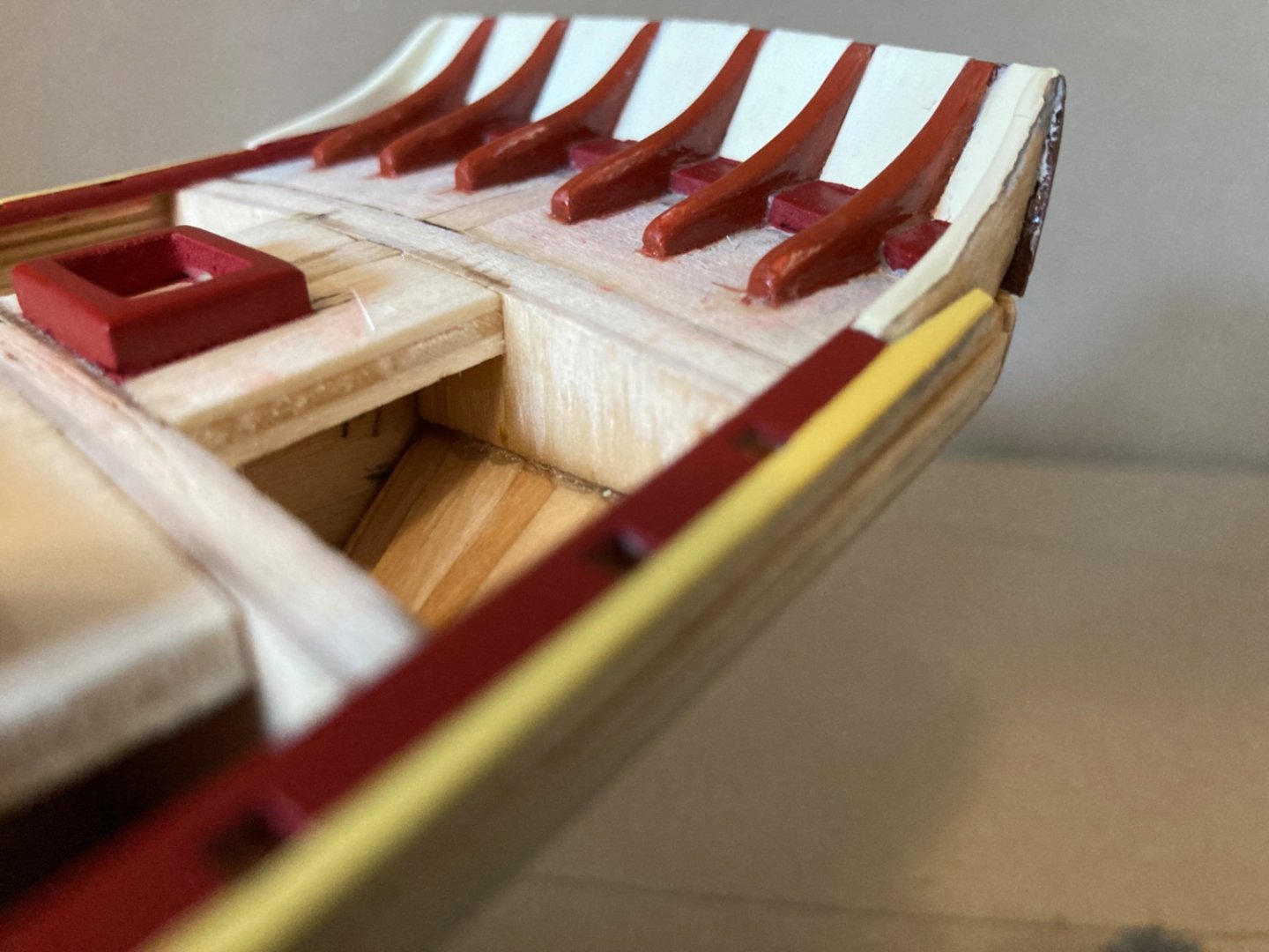
 It is now the 13th month of the real build timeline. All the work on hull, stern, bulwarks and deck were finished and the model was put and stored in a closed space. It was time to start building the deck structures. There were various structures on the deck and bulwarks such as cabin tops, hatches, deck lockers , fife rails, vent boxes, binnacle, steering wheel and wheel box, windlass, channels and many more. These are described in Stage E section of the instruction booklet. In the real model building timeline almost all the structures were manufactured first and painting them all together was done afterwards. However I will post each structure separately , including the manufacture and painting stages of that particular structure together, in order for the viewers to follow the building process more easily. I will start with the cabin tops and hatches. However all the photos of the aft lazarette hatch are taken with the binnacle, wheel and wheel box together, so those structures will be including in the posts regarding the hatches. Let's start with the main salon top. This structure is similar to the after cabin top and both have planked roofs and have companionways. I decided to keep companionways open in both structures. This means the deck below to be seen from the openings must be handled . I decided to plank those deck areas with 0.4 pear strips. This pear planked piece is manufactured and kept aside until the final assembly of deck structures. After the four sides of the cabin top were done squarely , the top was covered with 3 sheets.The side walls of companionways placed . The structure at the fore side of the structure is manufactured separately and put aside. The arc structure at the companionway was cut out from a piece of wood. Then the sliding top of the companionway was built. The wood steps at this stage was fore demonstration only. The roof planking was planned. Edge planks were mahogany and inside planks were same as deck planks. The inside planks were build in 3 sections. After placing the edge planks the inside planks were installed. Then the inside planks were stained. Sanding sealer was applied.The sidewalls of the structure was painted light cream. Companionways and sliding top were mahogany in color. The number at the entrance was a decal. That number detail was taken from a photo the ship. After the painting job, the finished structure was put and kept in a closed organizer box until its final installment. This was what I have done with all the other finished structures. Here are some photos of the main salon top. Sliding top of the companionway and the structure at the fore edge of the main salon top were not permanently glued at this time.


- 114 replies
-
- 3
-

-
- Pride of Baltimore II
- Model Shipways
- (and 1 more)
-
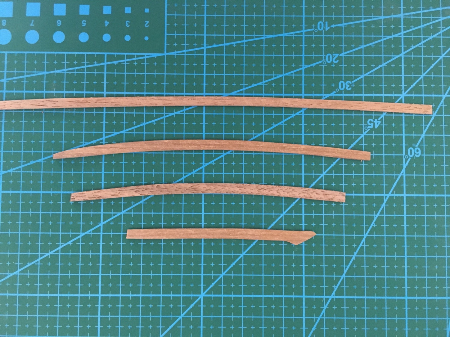
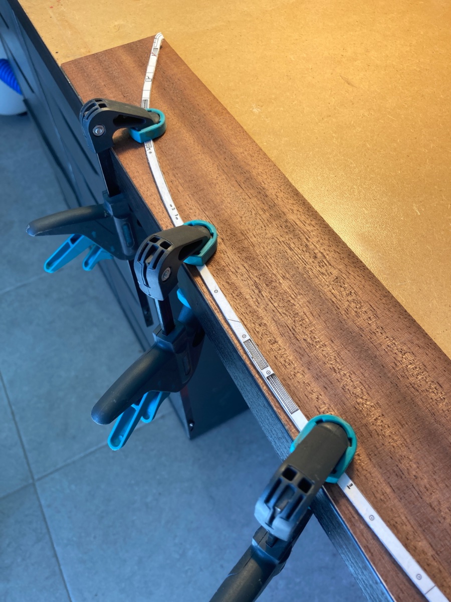
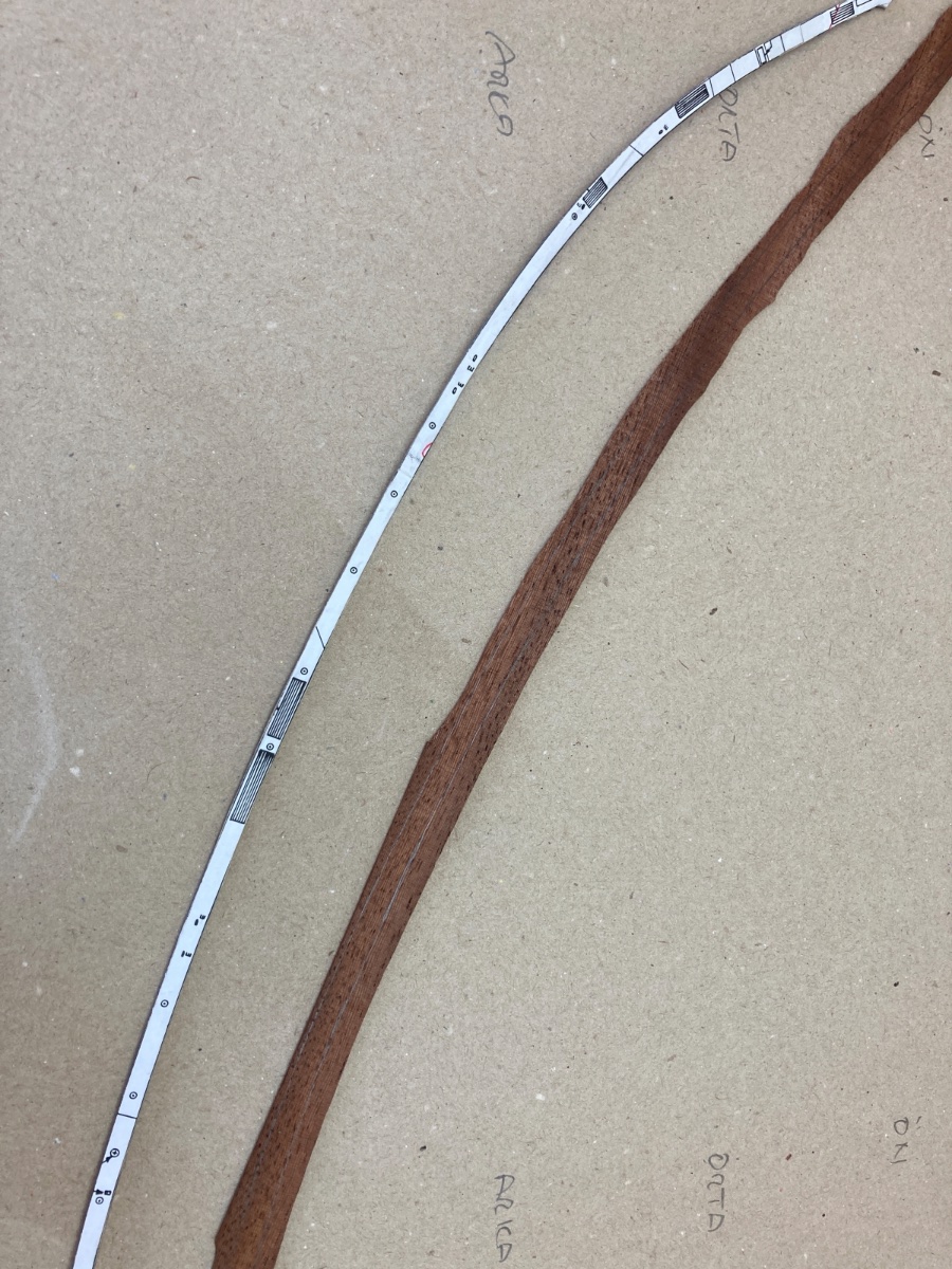
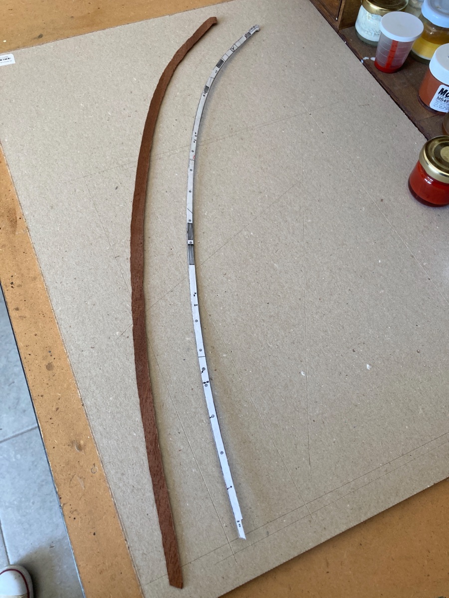
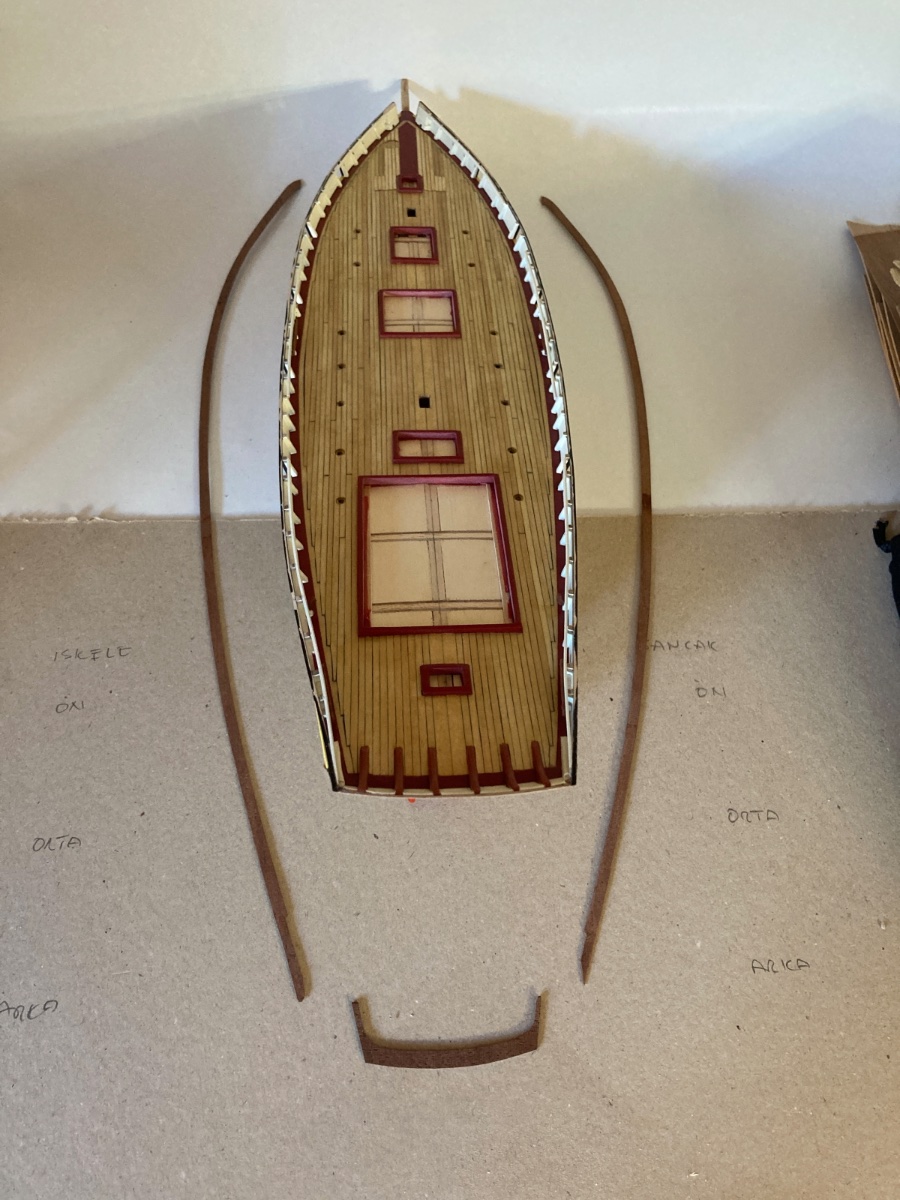
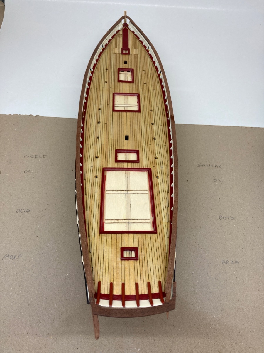
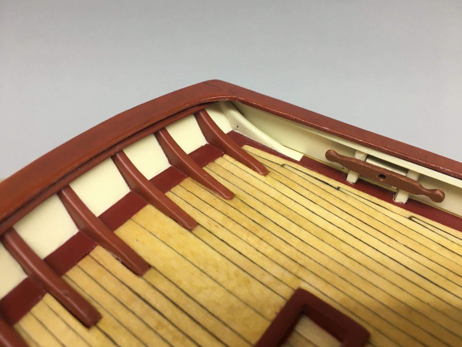
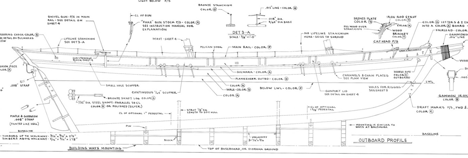
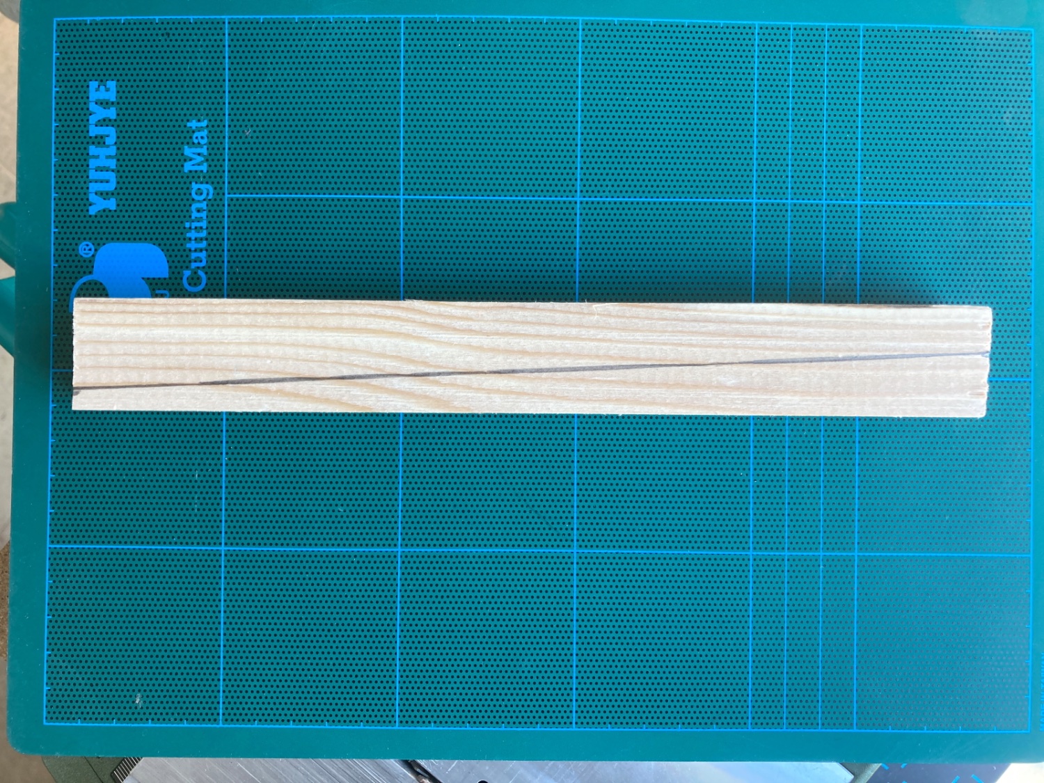
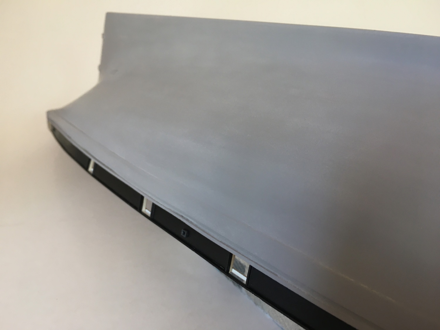
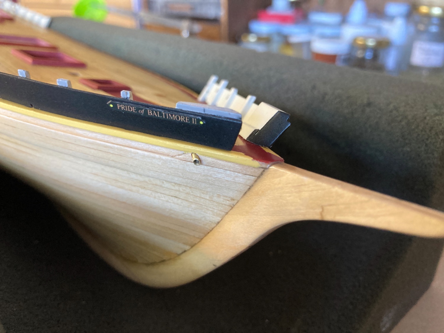
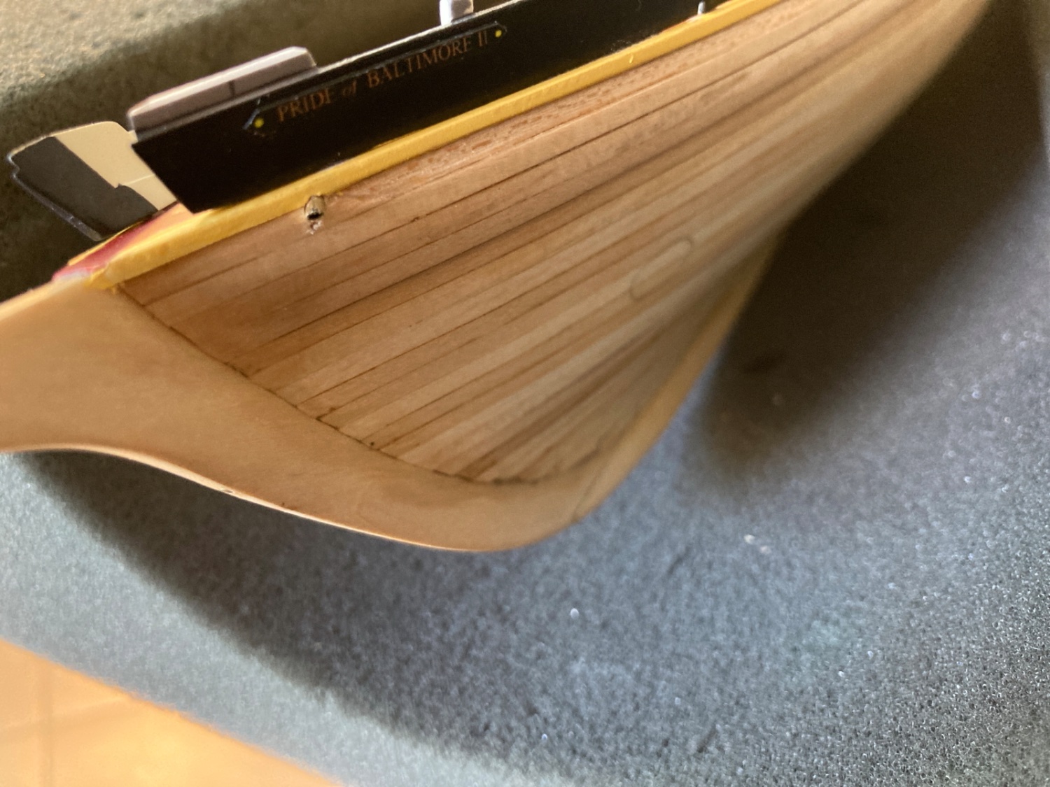
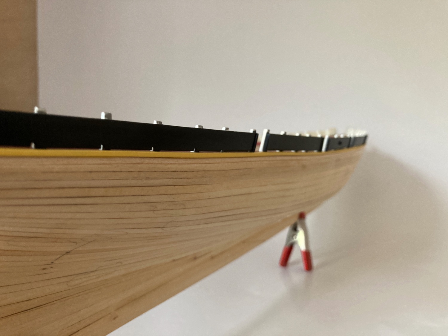
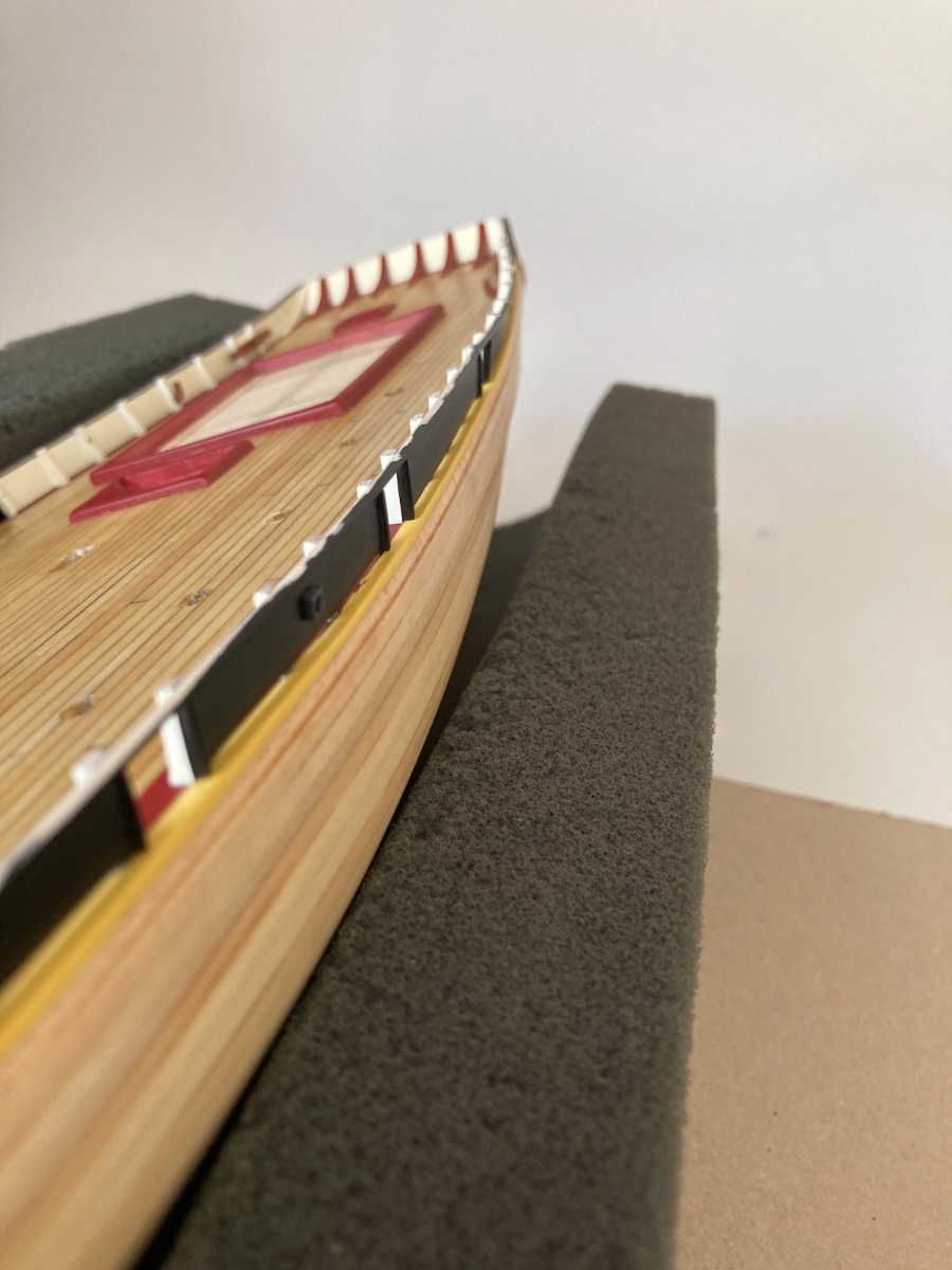
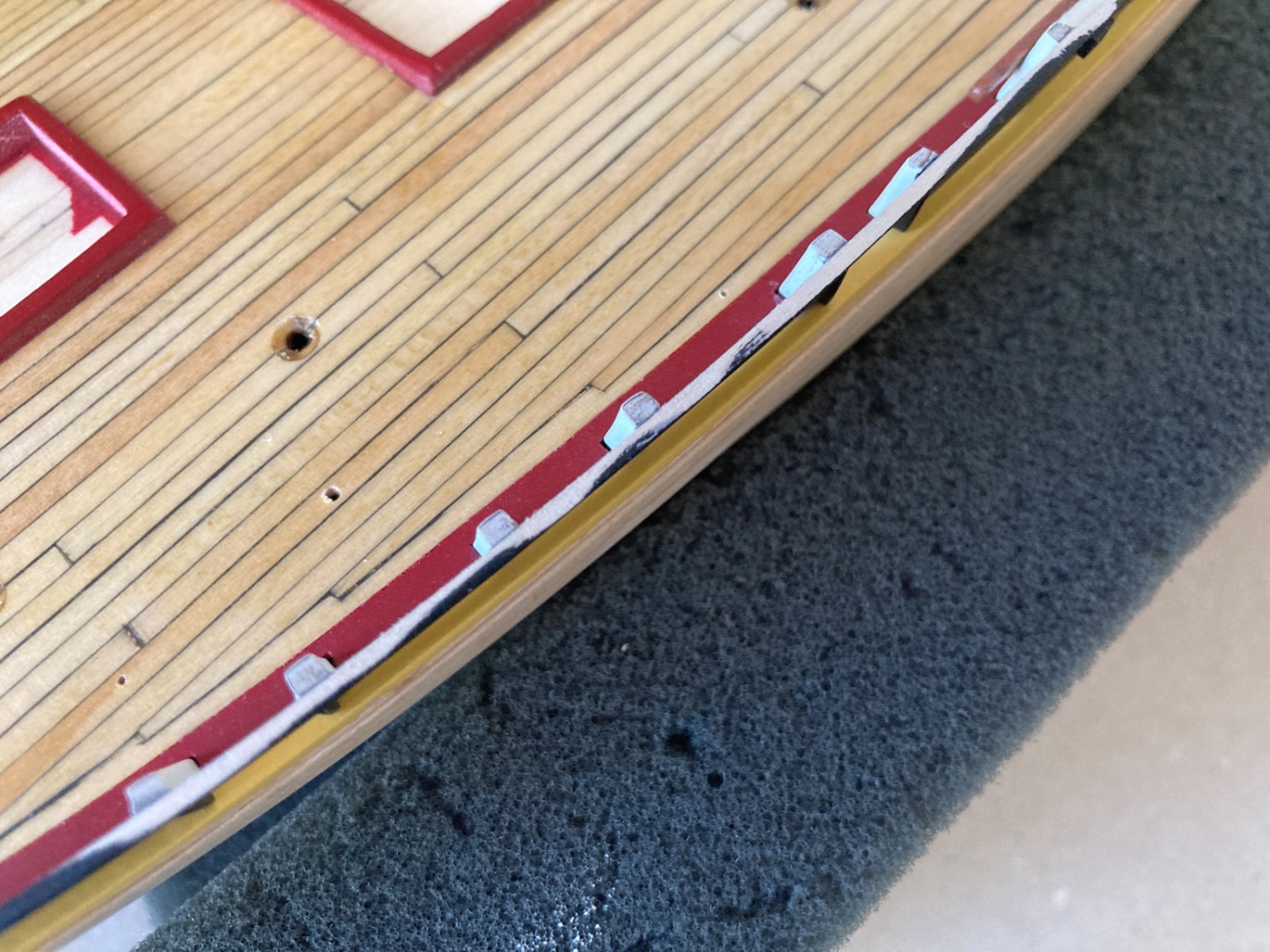
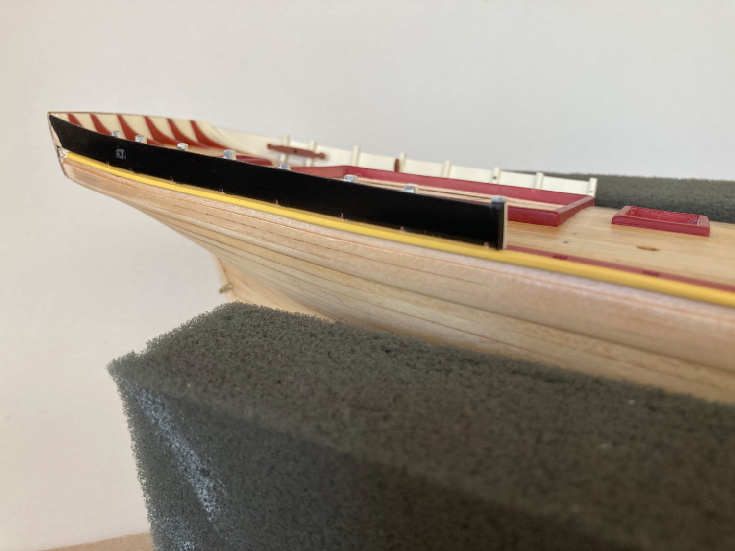
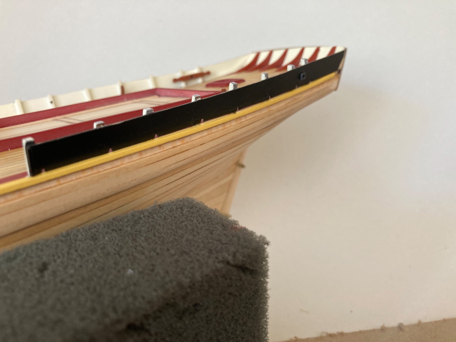
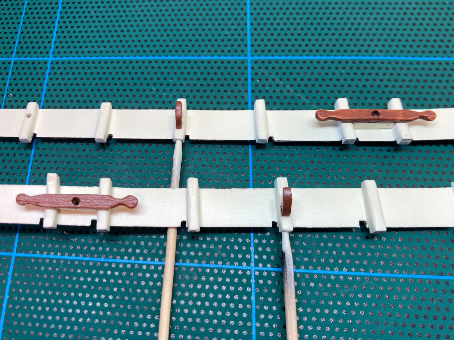
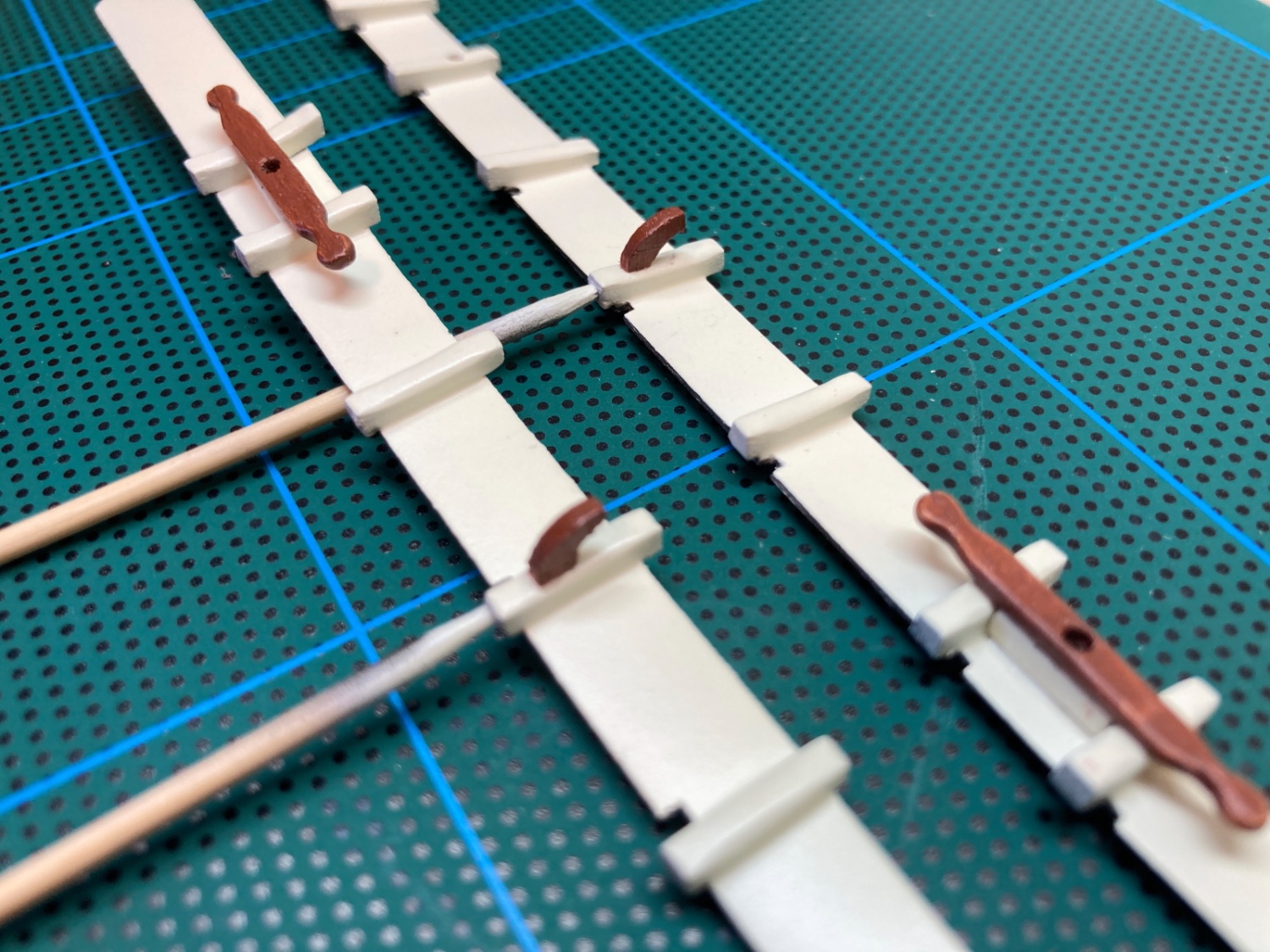
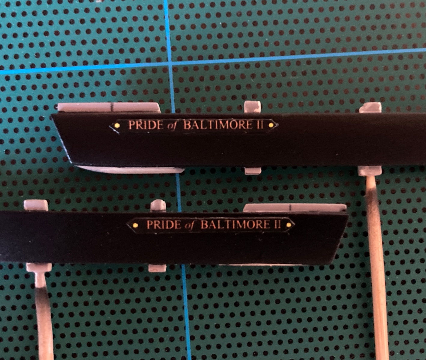
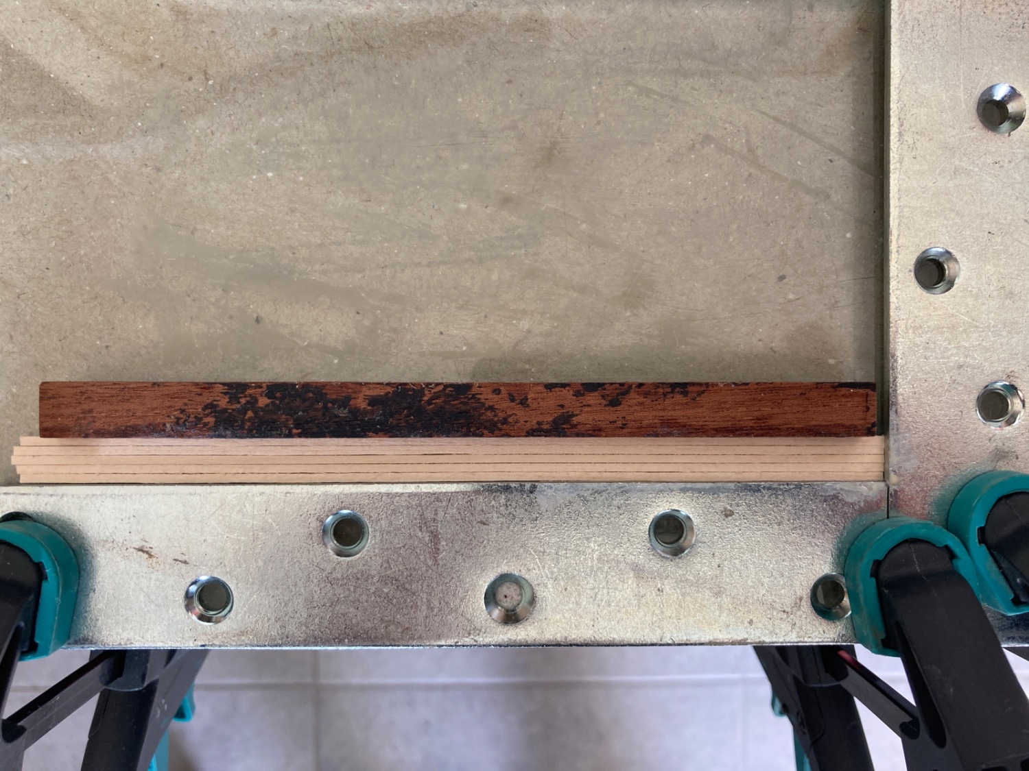
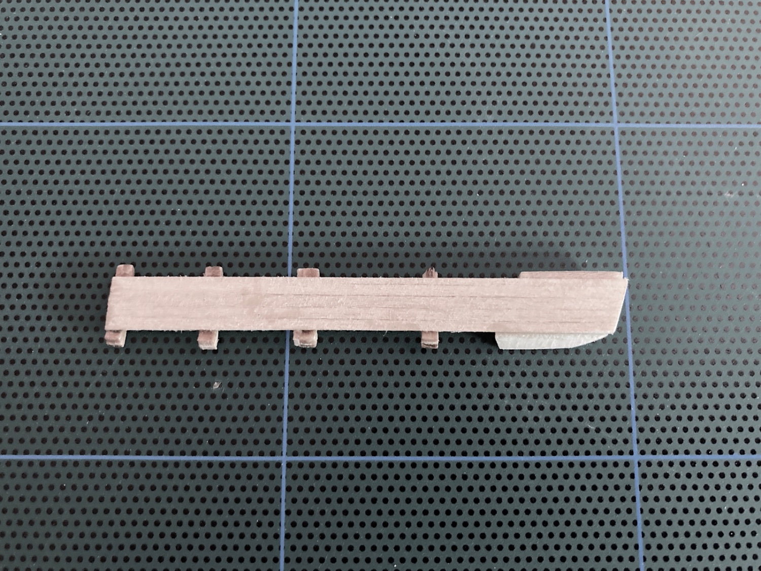
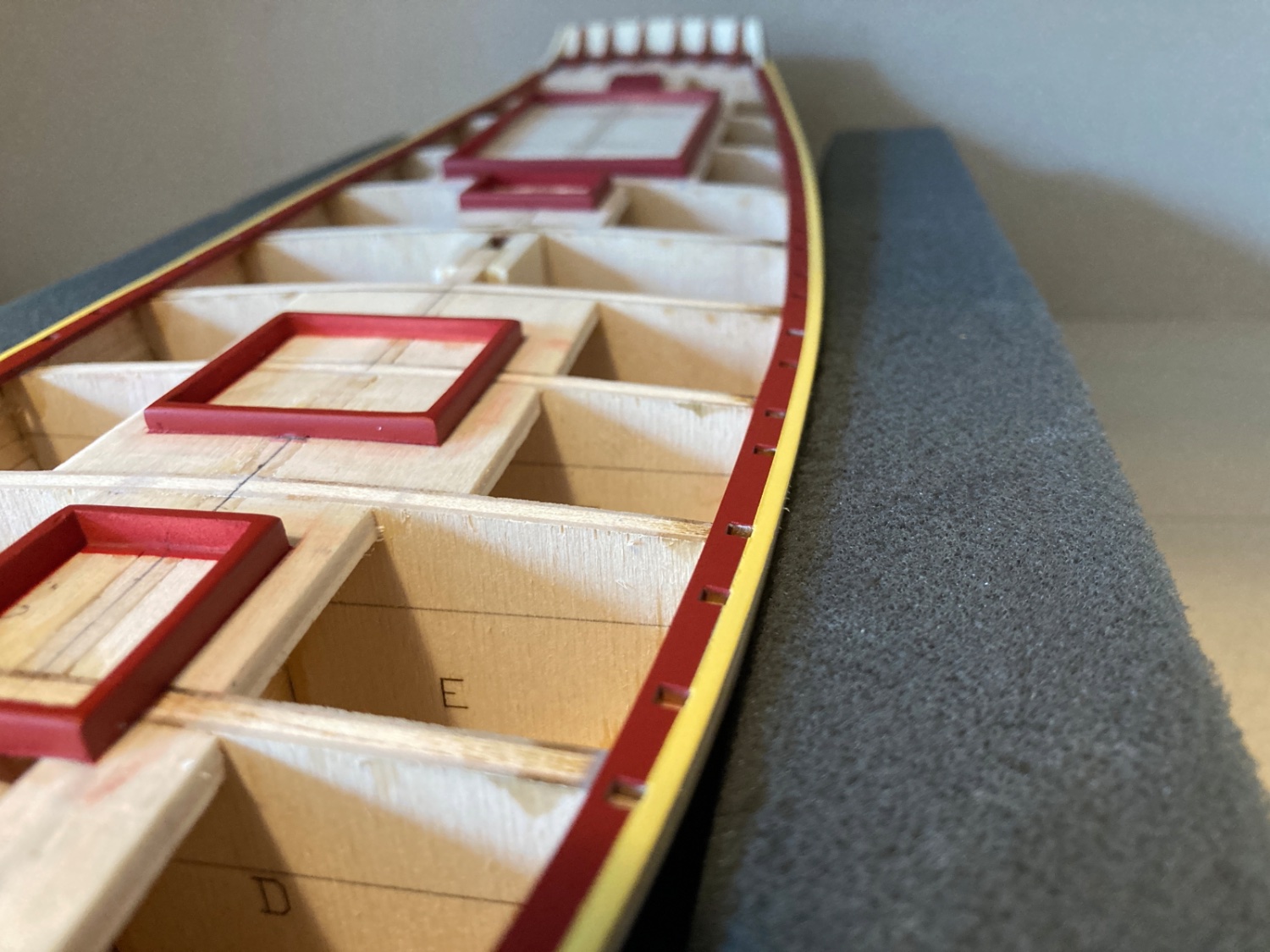
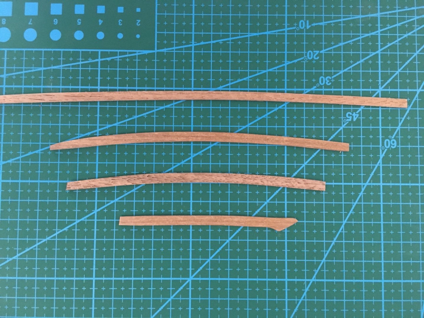
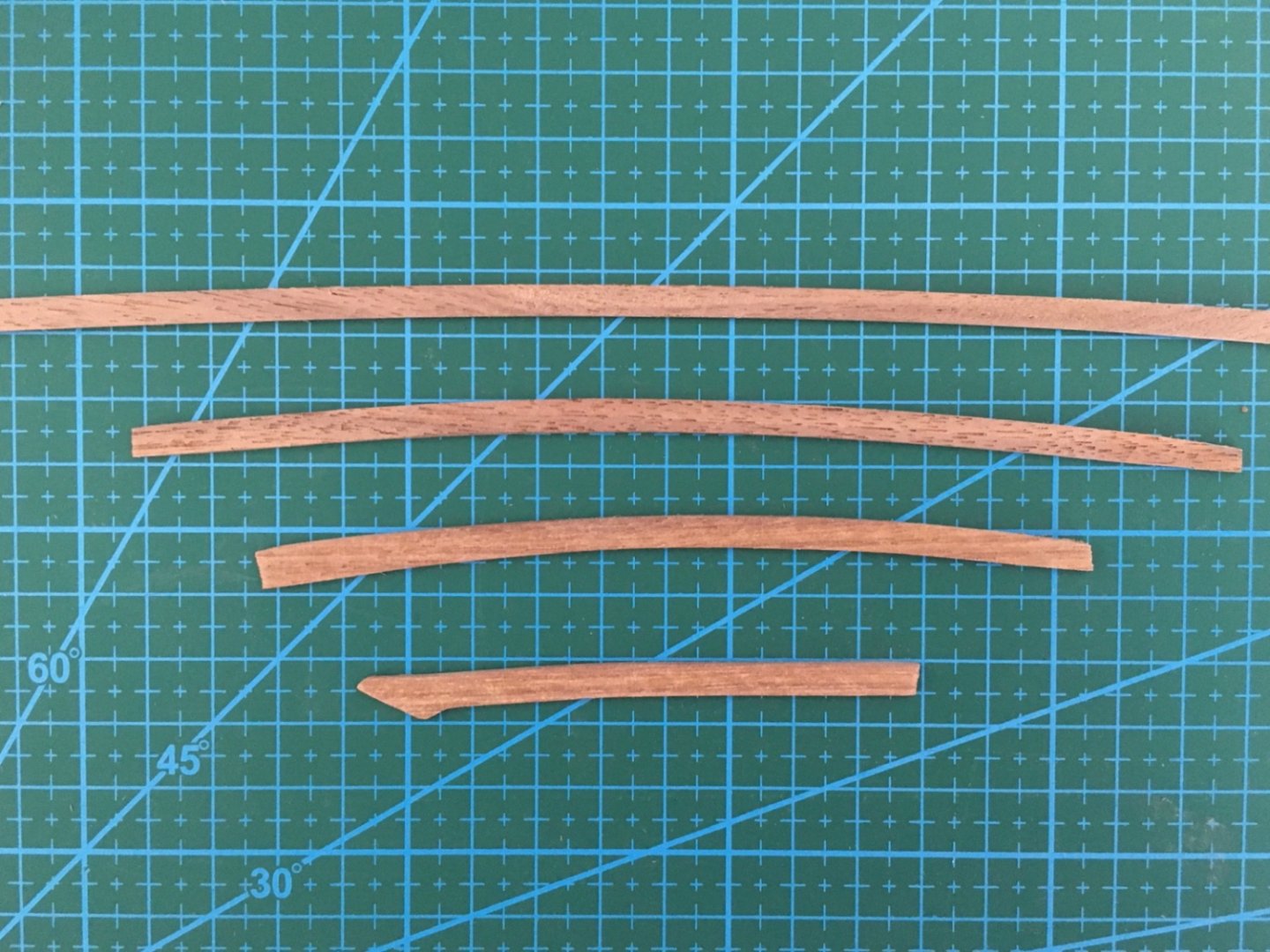
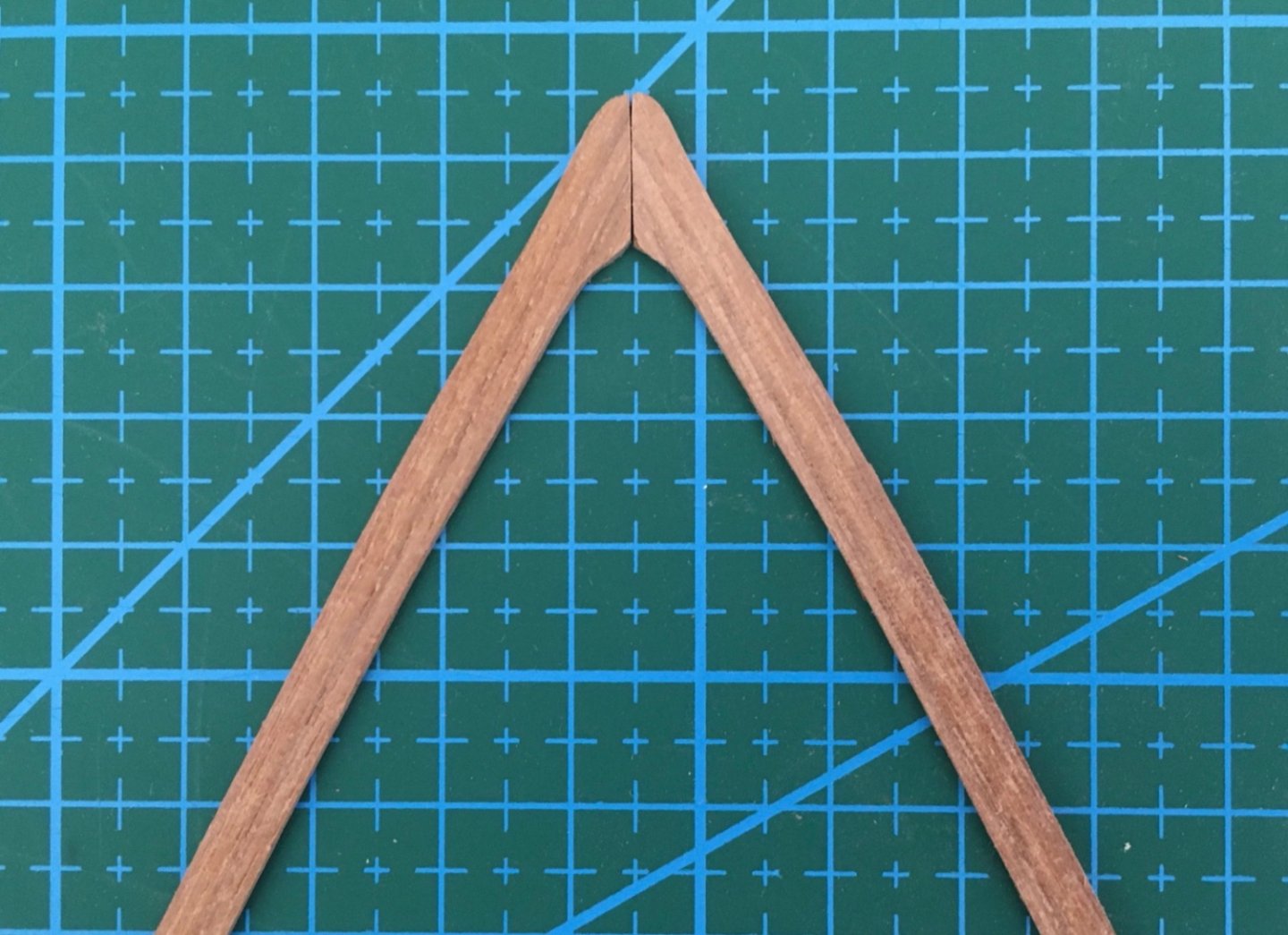
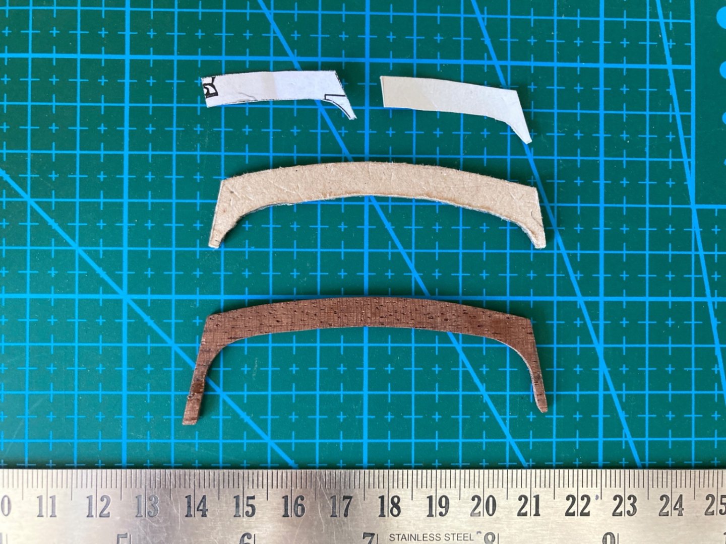
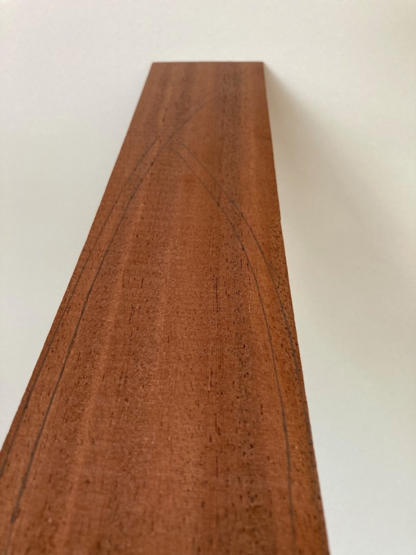
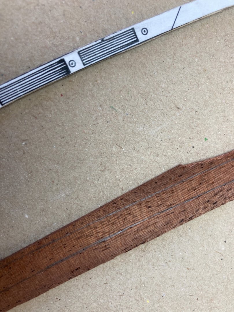
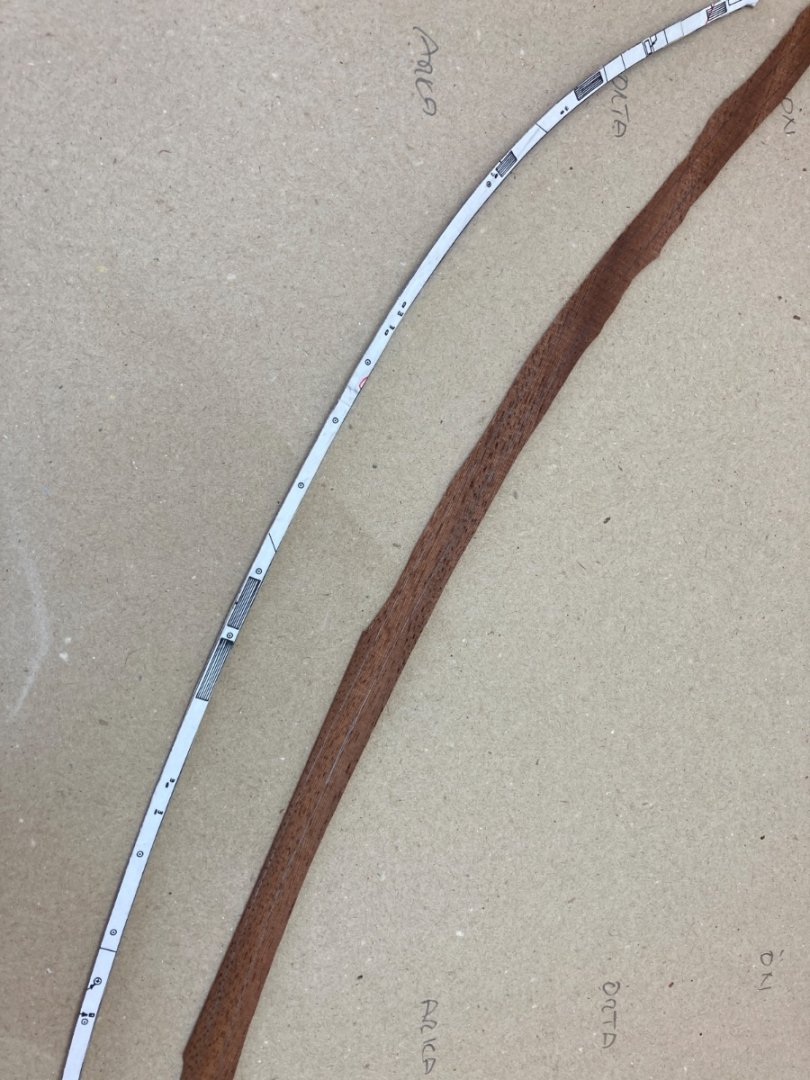
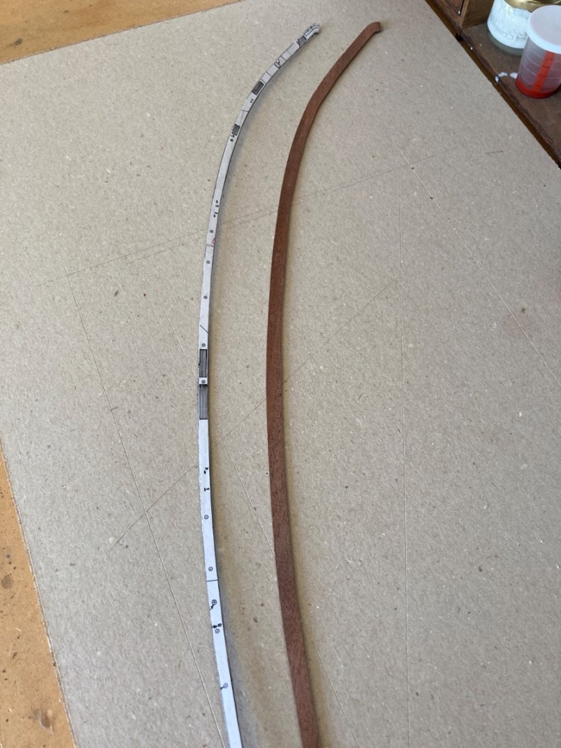
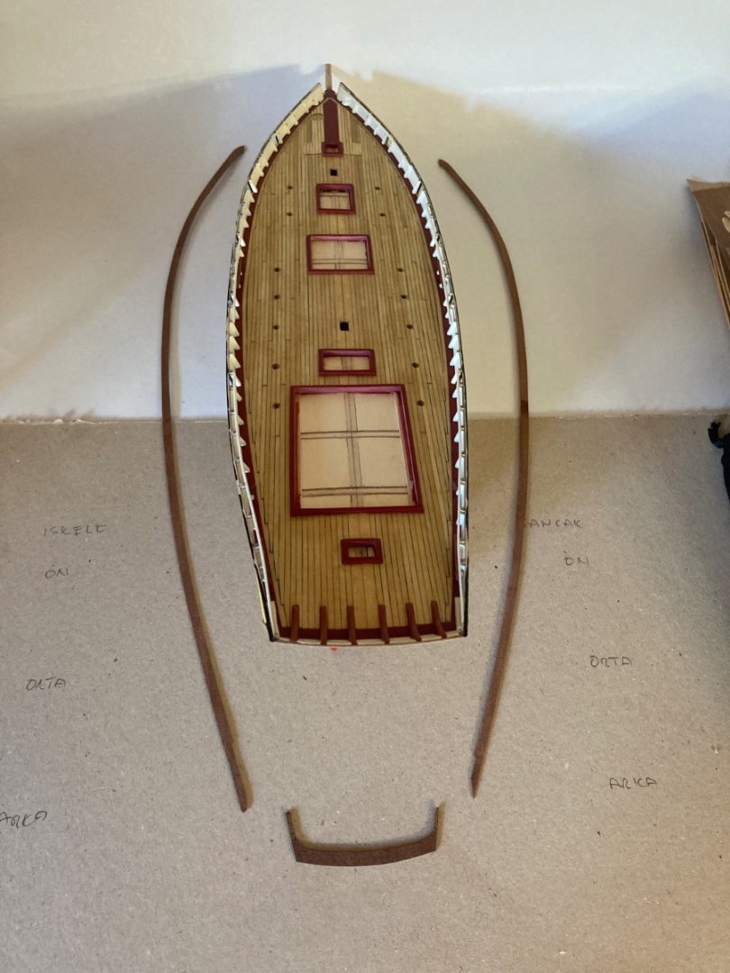
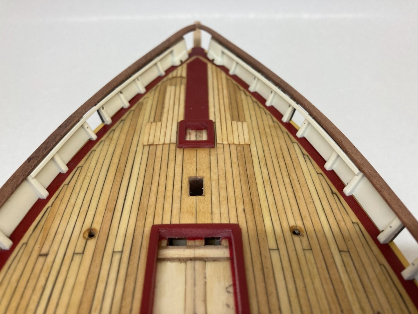
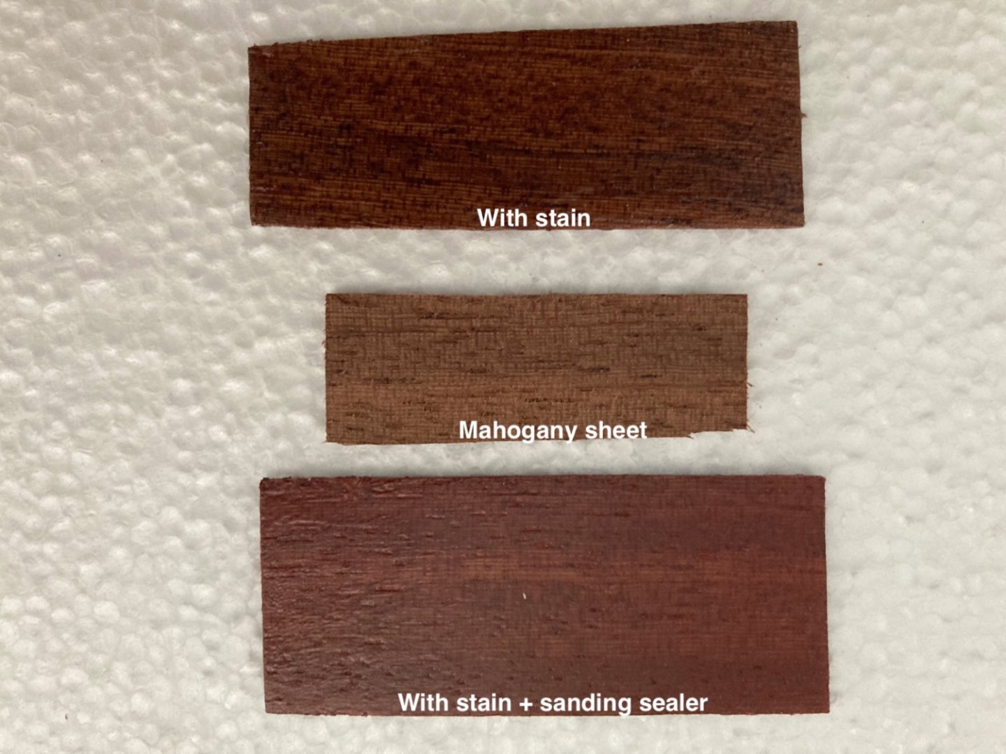
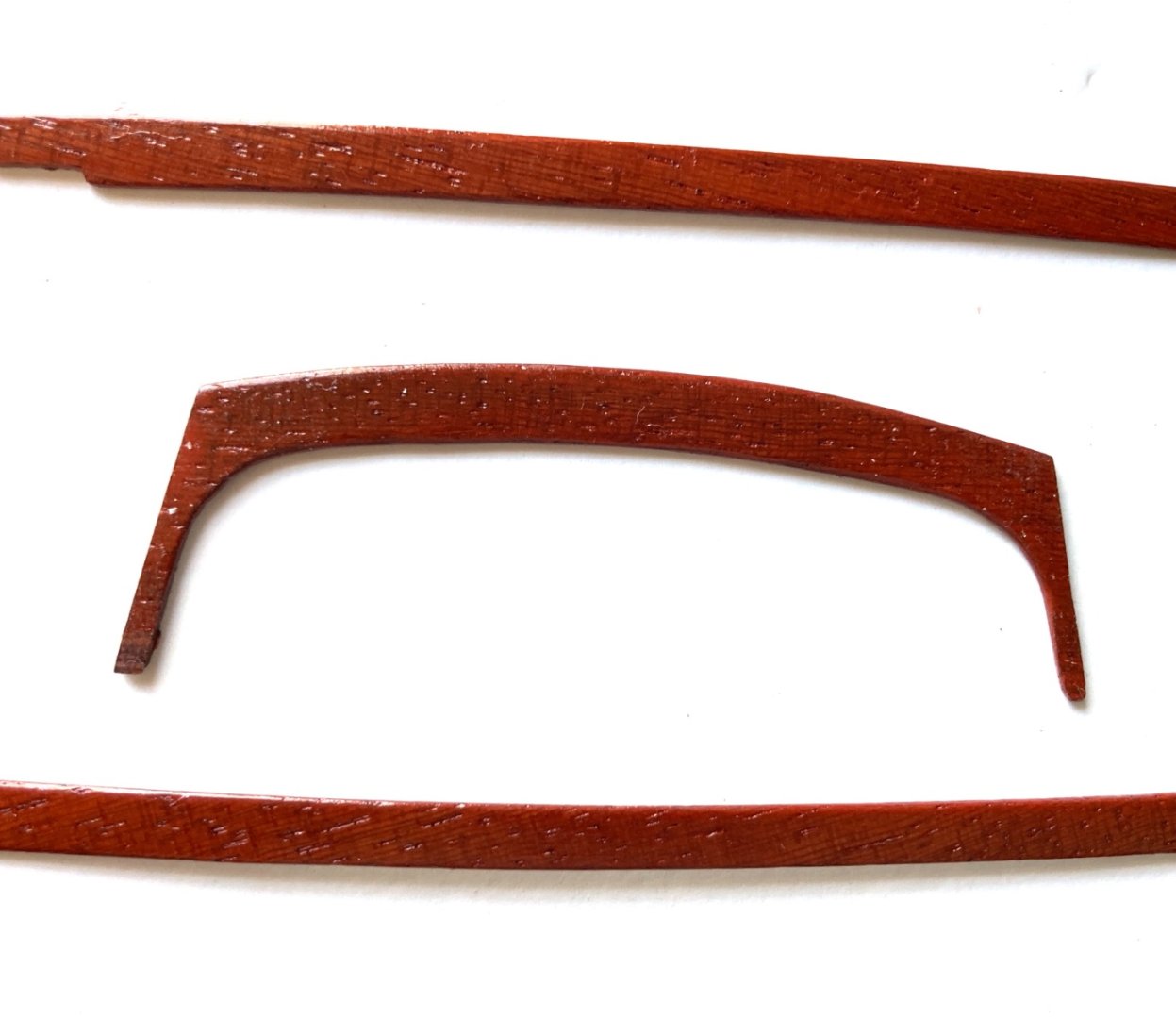
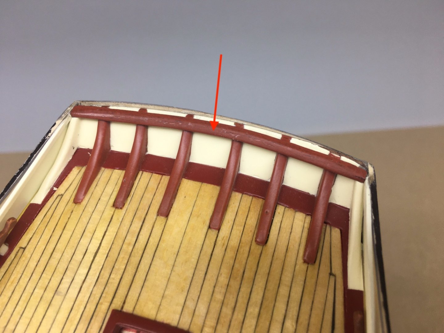
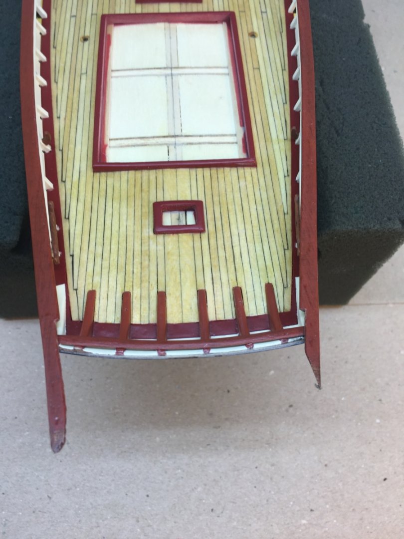
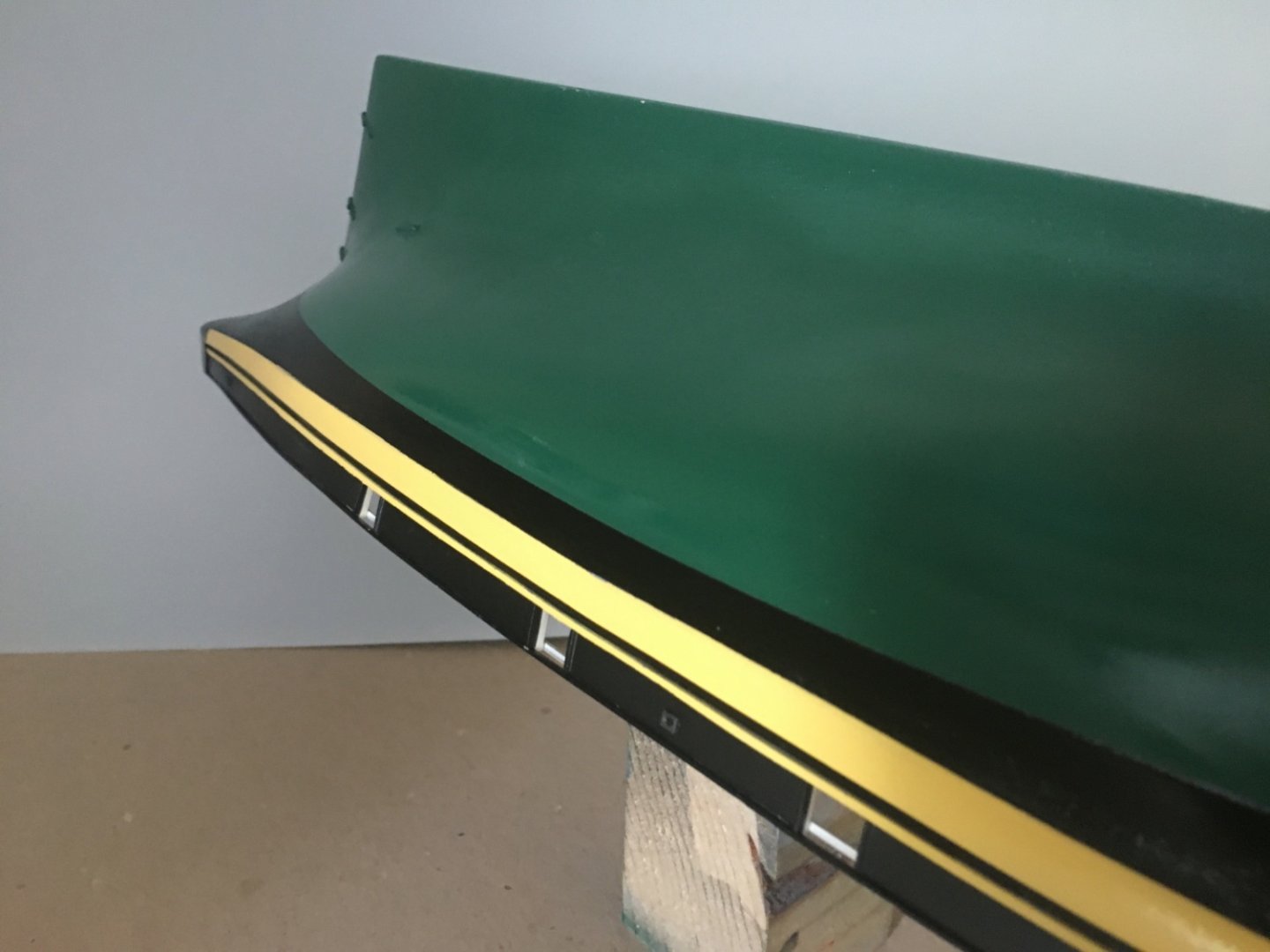
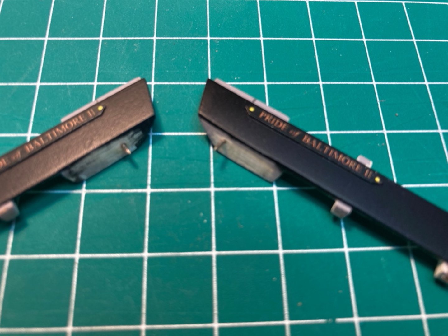
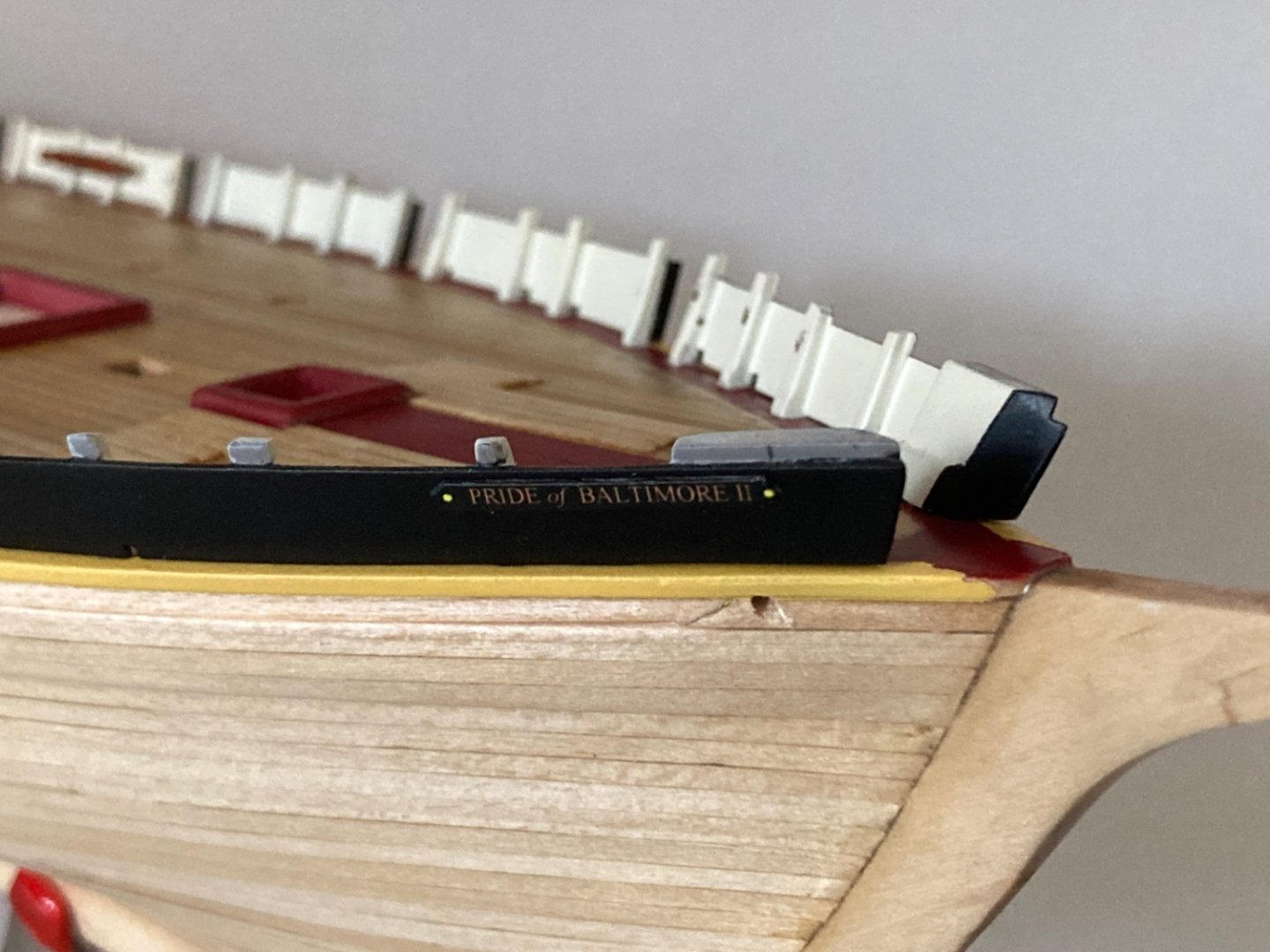
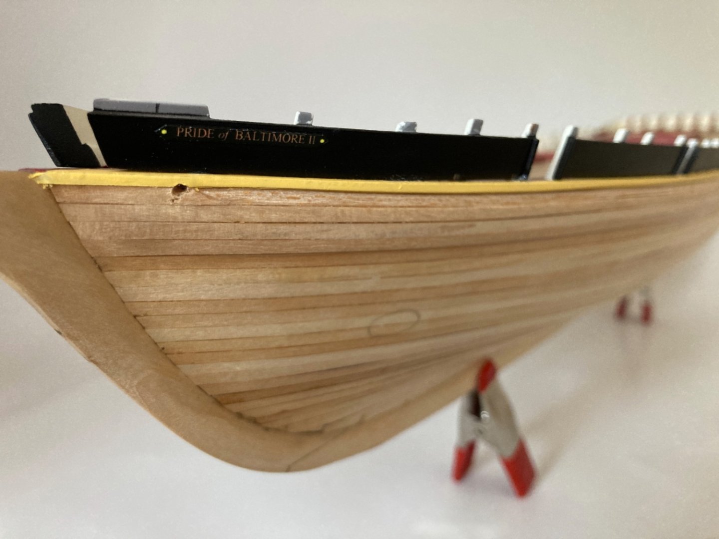
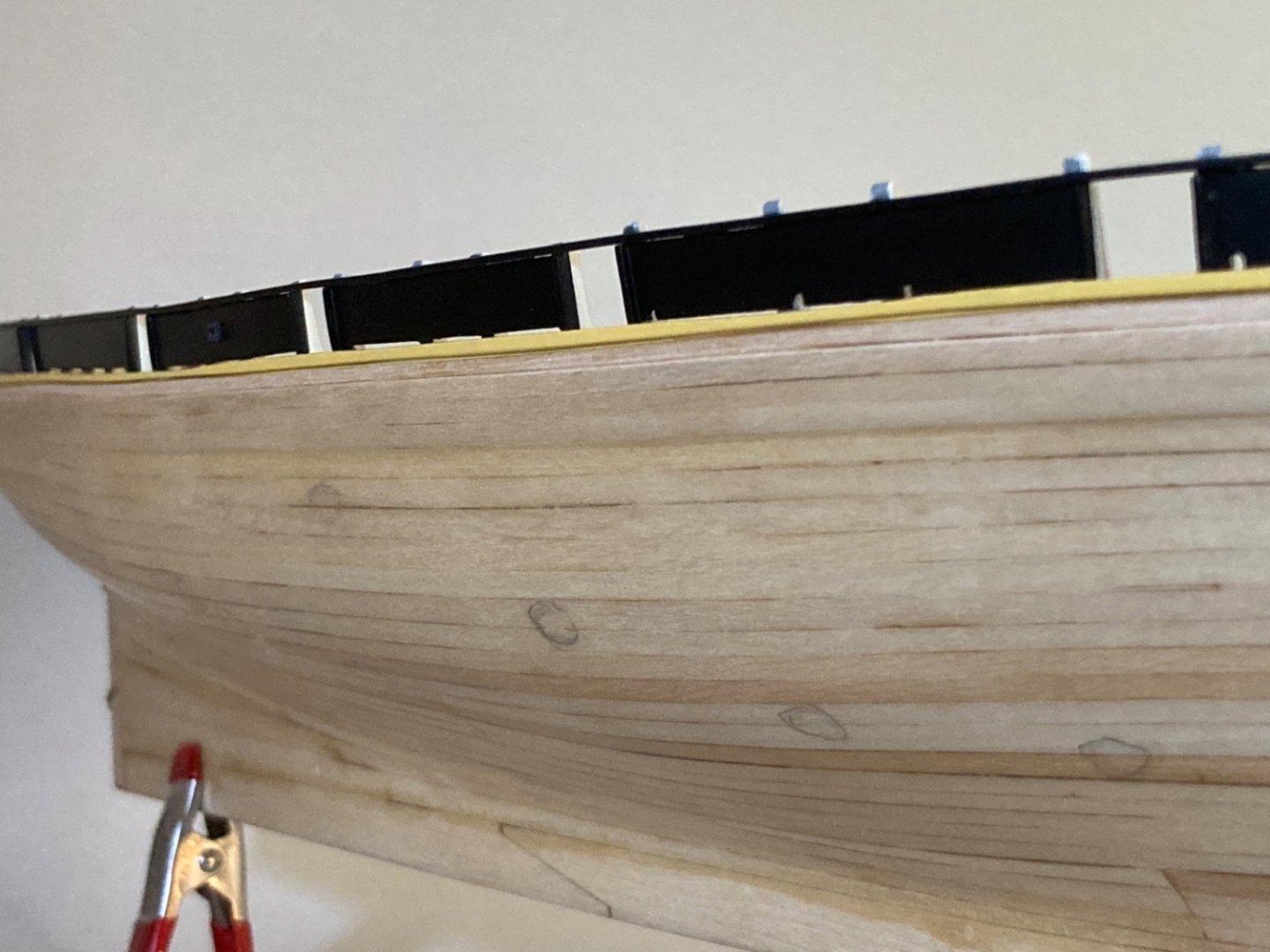
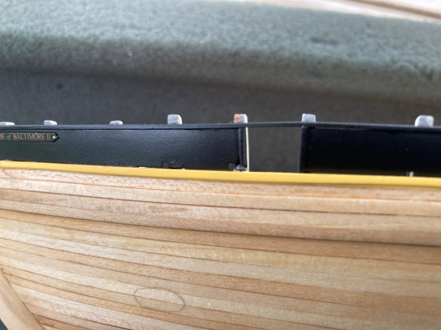
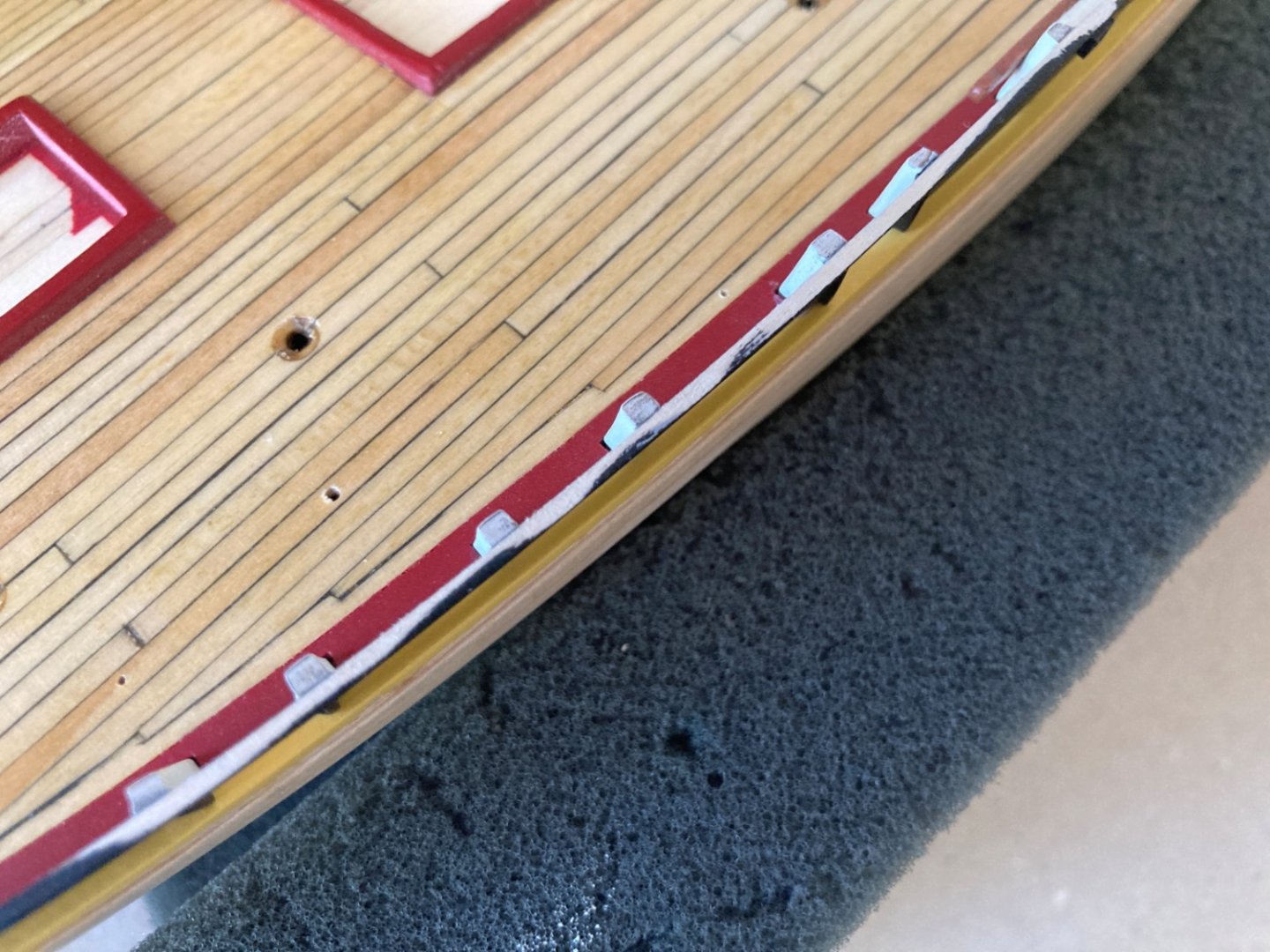
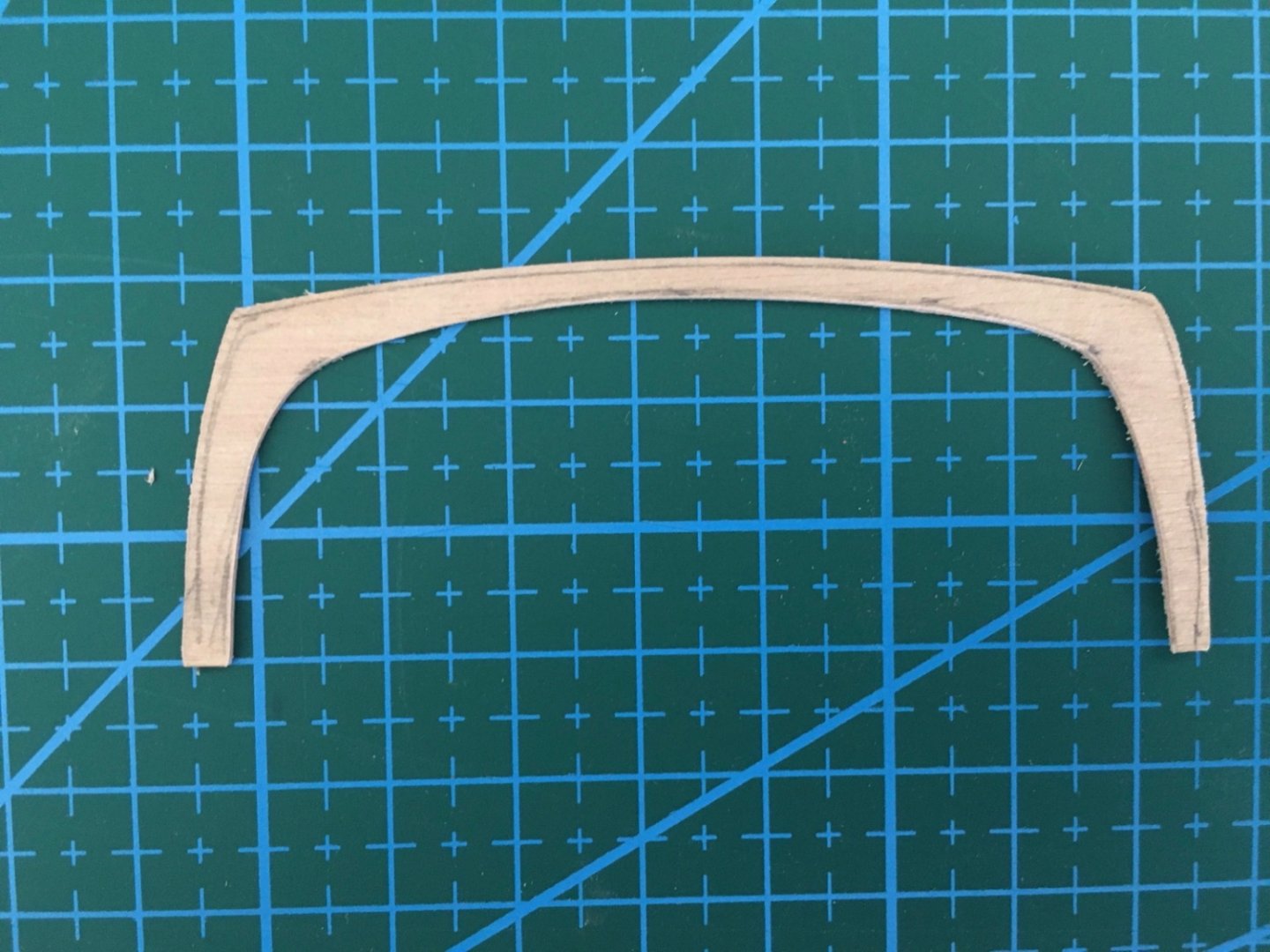
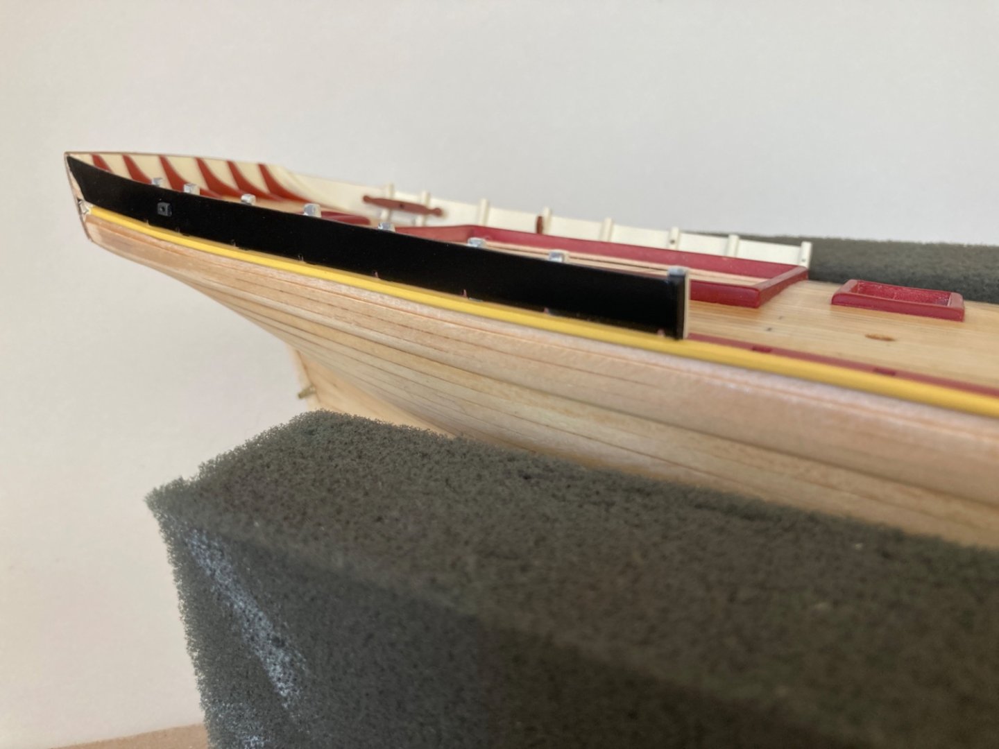
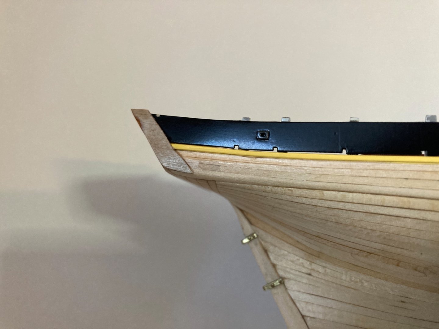
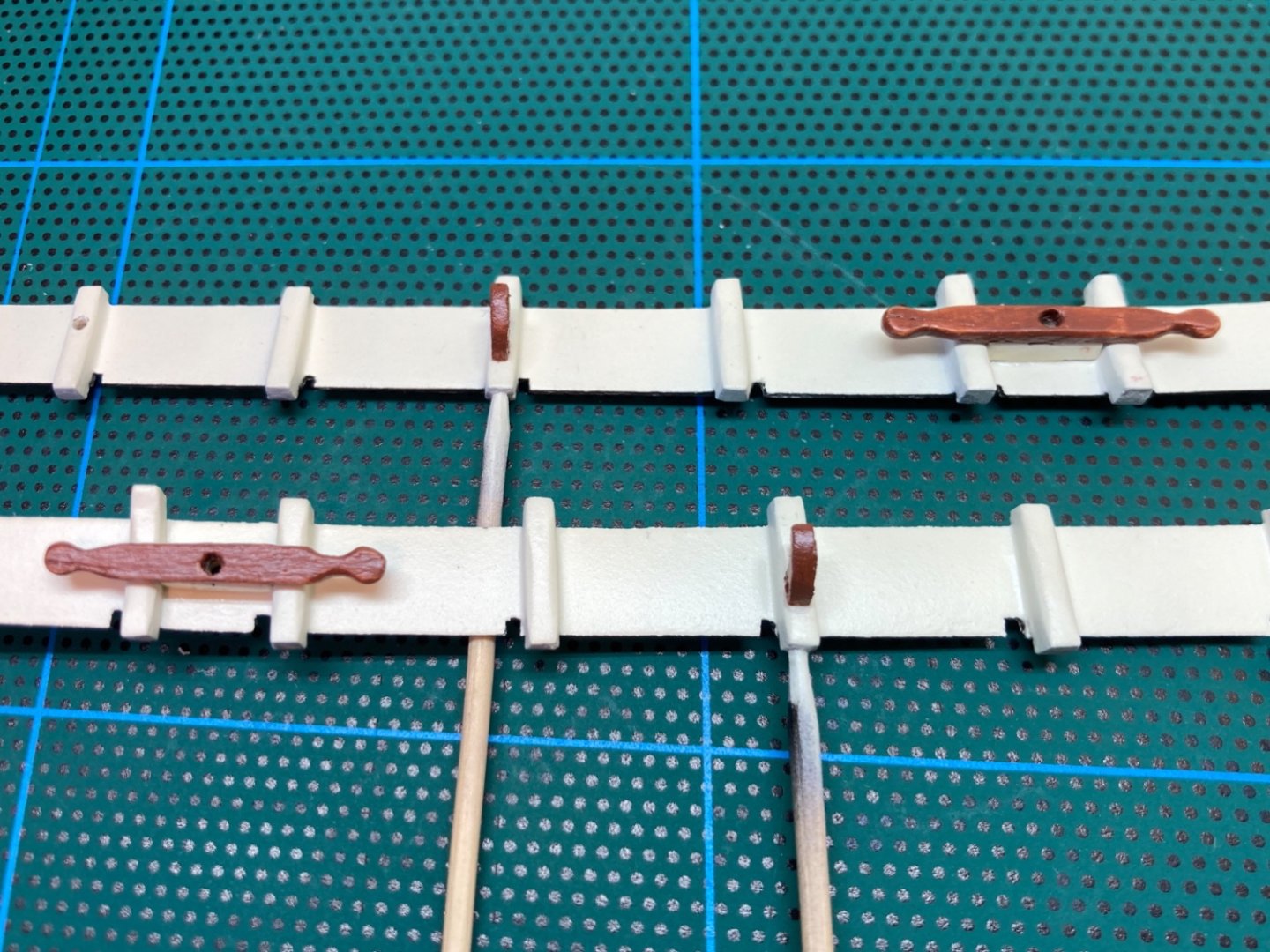
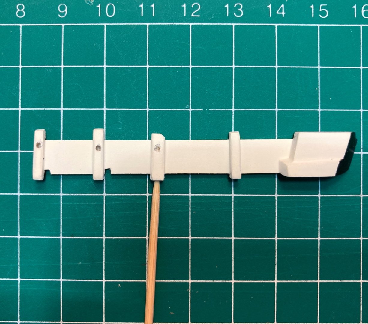
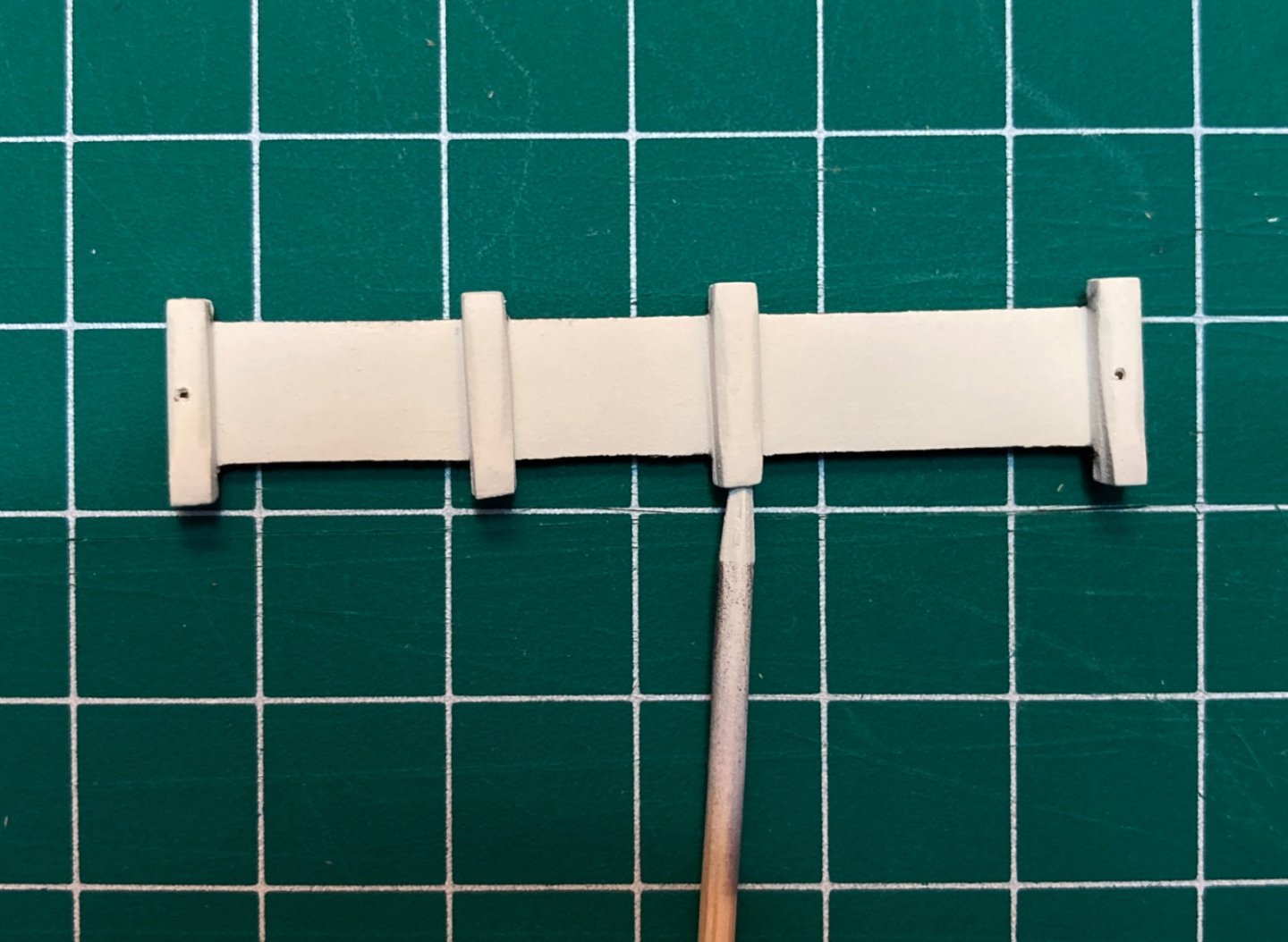
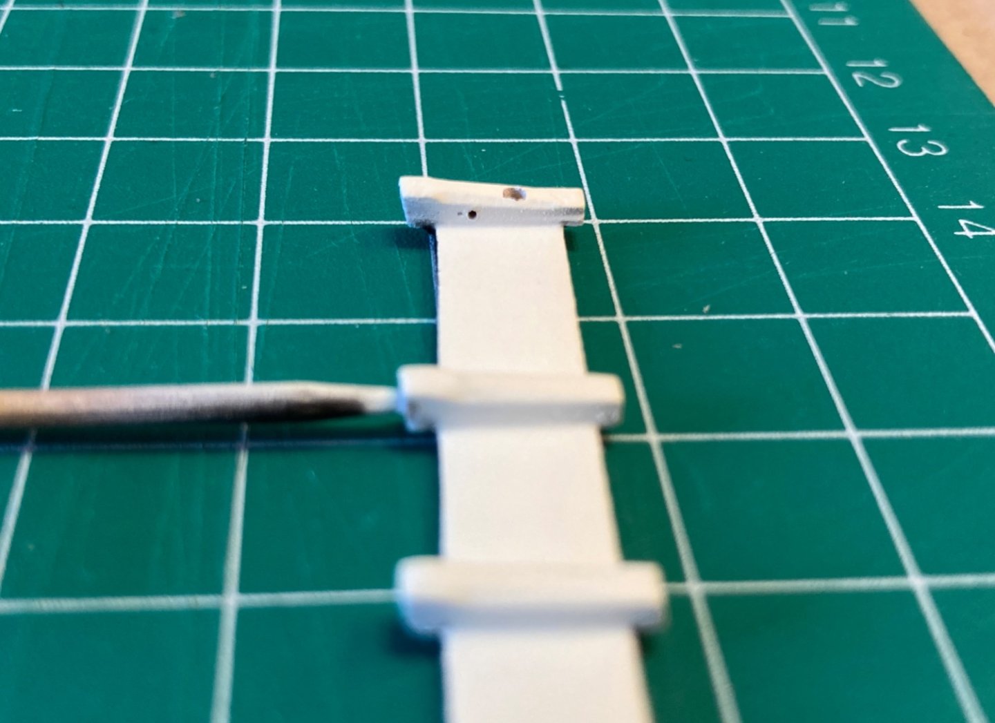
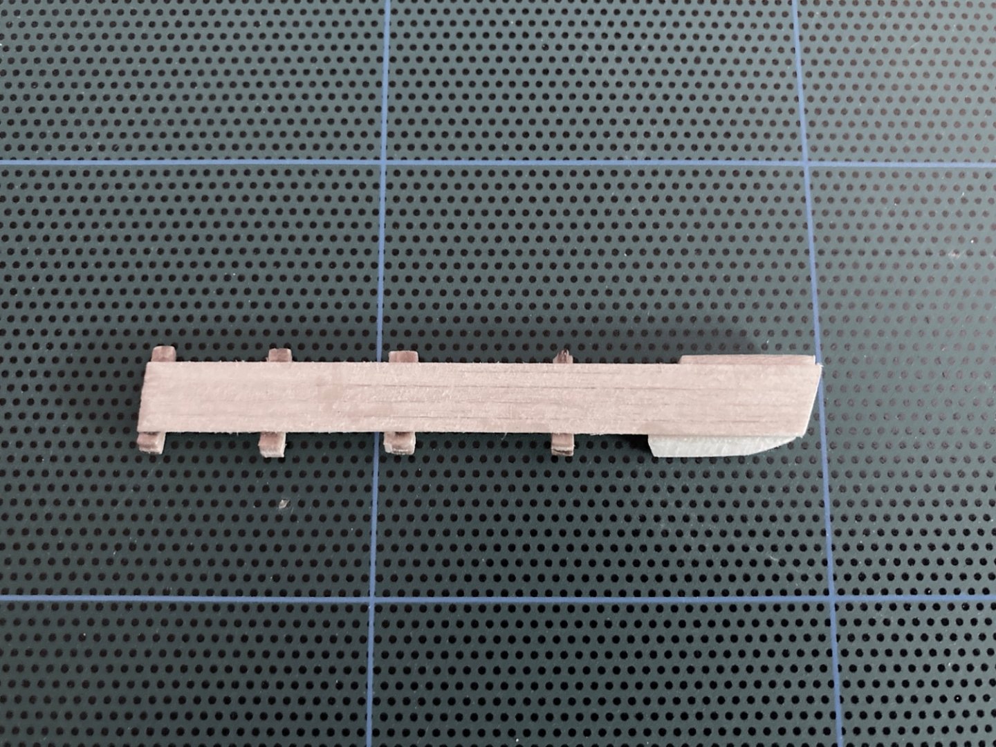
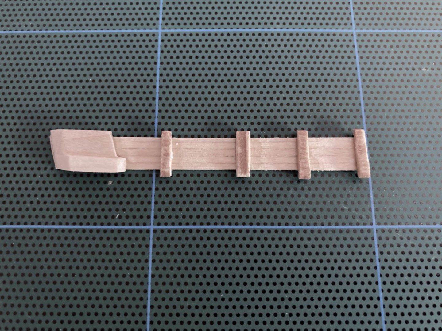
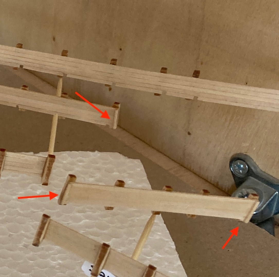
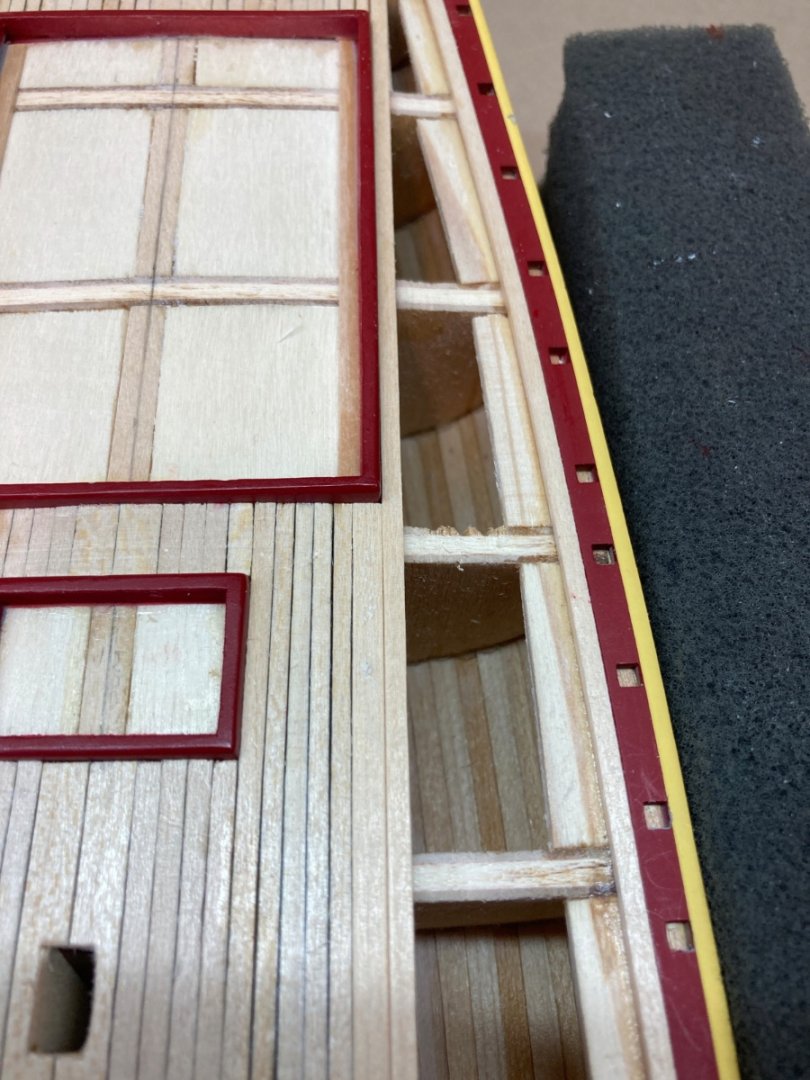
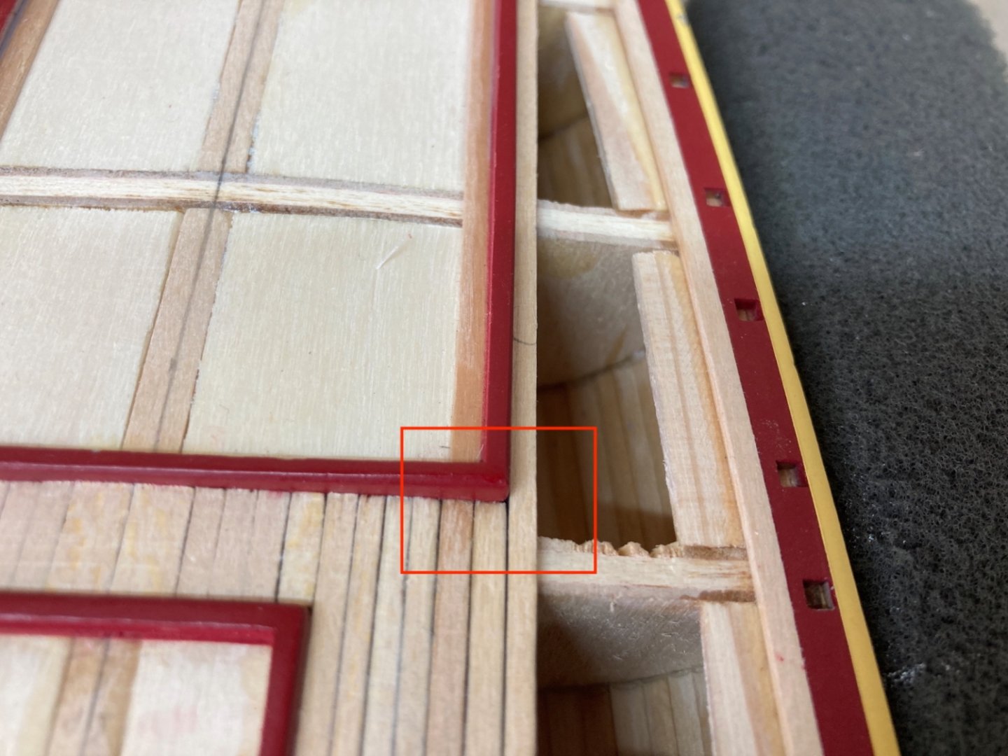
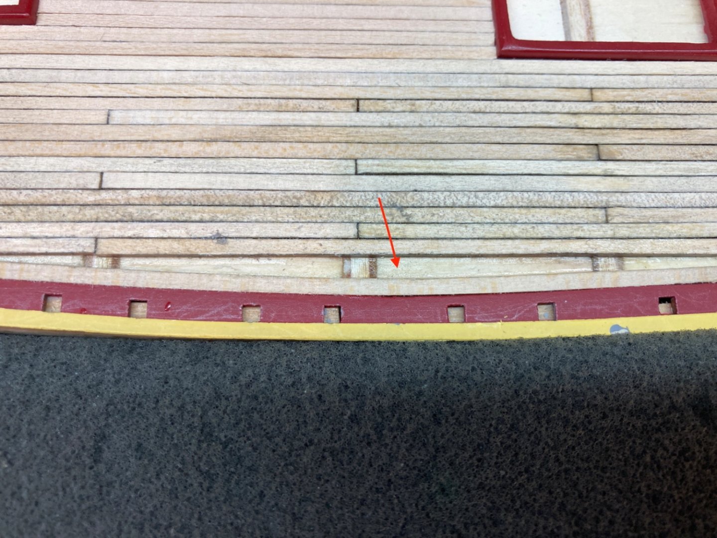
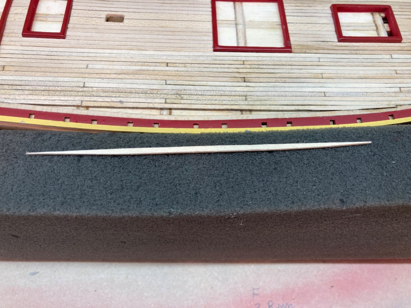
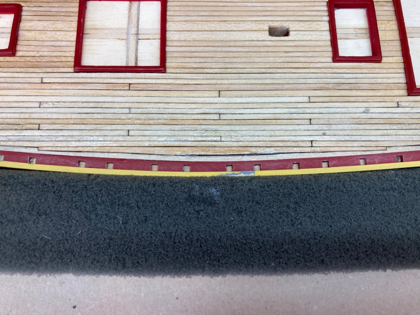
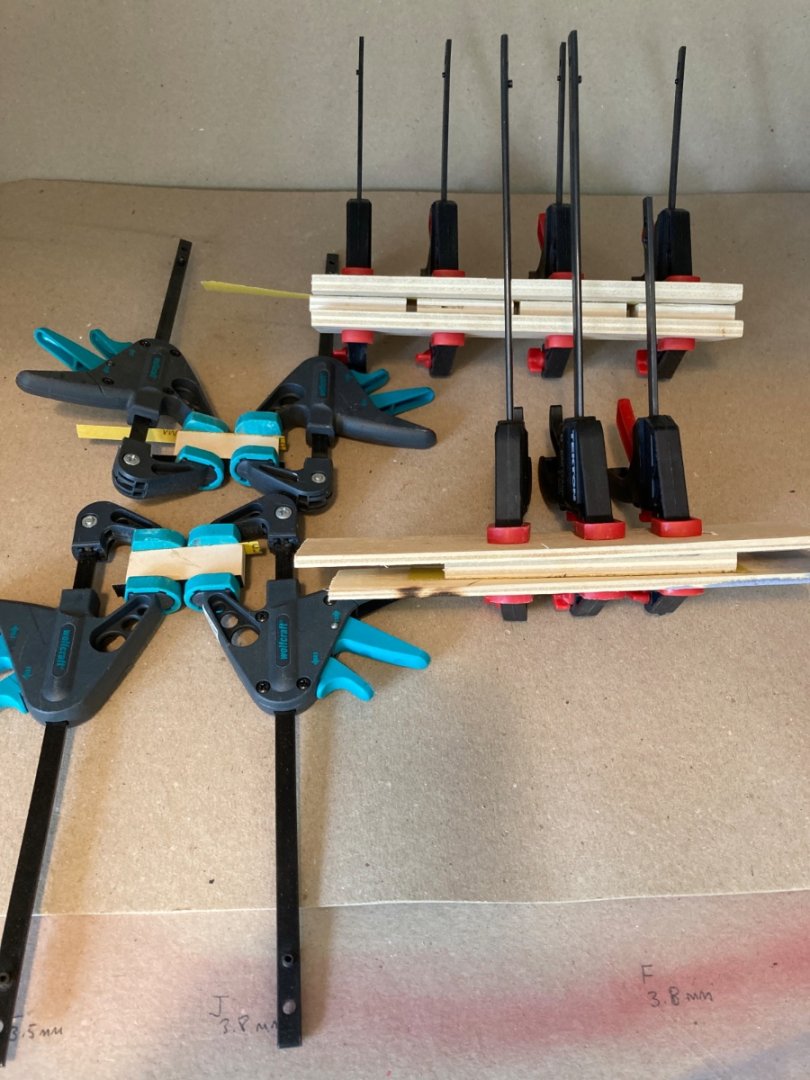
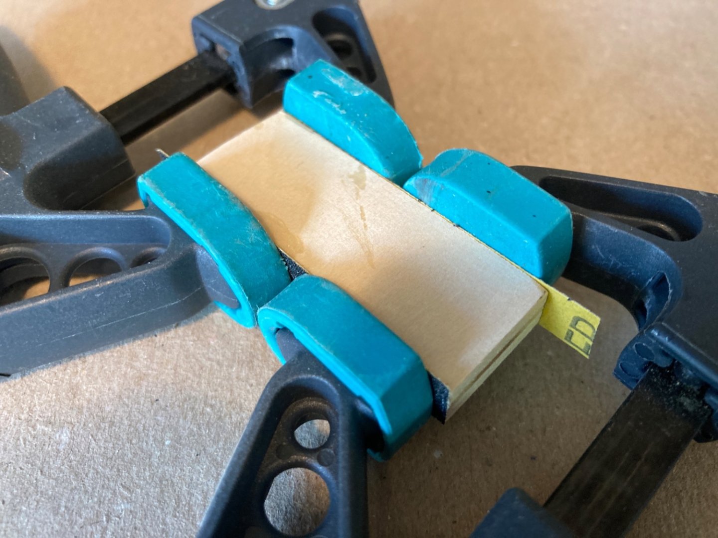
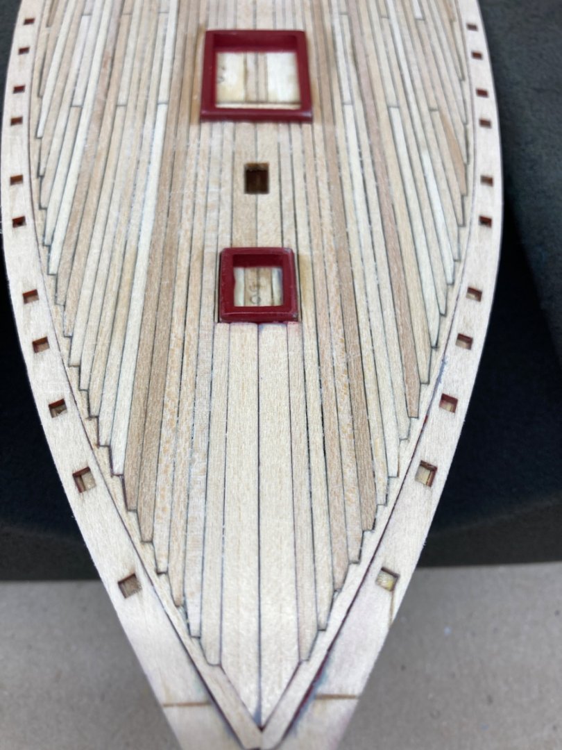
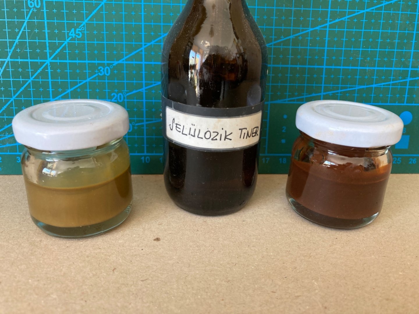
Next comes the installation of the main rail of the bulwarks. The main rail was already prepared before the painting of the hull. Initially I followed the kit's instructions and planned to prepare the main rail as 3 separate pieces . As the finishing of the rails were mahogany in color, I decided to manufacture them directly from mahogany wood instead go basswood. Here are the photos of the initially prepared main rail pieces However in a later stage I changed my mind and decided to prepare them as one piece at each side also from mahogany wood. I cut out the rails from the plan in three pieces; port, starboard and stern pieces. They were glued to 3 mm cardboard and then cut carefully. They were placed on mahogany sheet and after fixing the cardboard with clamps, the outline of the rails were transfered. The stern piece Port and starboard side pieces transferred to wood. The rough cutting of the pieces were done by using Proxxon KS230 Table Saw and Proxxon DS230 Scroll Saw . Then work was done by Dremel large and small drum sanders. Finally suitable sanding wood blocks were used. Final shapes and dry fitting Probably the main rails are the only structure in the ship with a gloss finish. In order to achieve the mahogany color better and the gloss finish, I decided to stain the rails with synthetic mahogany stain. Here is a photo of the experiments with scrap wood. Here is a photo of the rails after stain application After the stain several coats of sanding sealer was airbrushed to smoothen the surface. As the mahogany wood is porous in character more than several coats were needed. The final gloss coat was planned after the installation of the rails. The installation began with a piece (red arrow) right under the stern rail. First the deck and starboard rails were installed. Then the stern piece was trimmed to fit between the aft ends of port and starboard pieces. This step was followed by the trimming of the aft ends of the port and starboard pieces. The neighboring areas between the stern piece and the side ones were filled with mahogany wood sanding dust (to match the color) and gap filling CA was applied . This was followed by light sanding of those areas. Photos of the deck and the other parts of the main rail after installation. Please note that the model is fixed on the jig prepared for LWL drawing and touching the hull is minimized during the handling of the model.


- 114 replies
-
- 4
-
-

-
- Pride of Baltimore II
- Model Shipways
- (and 1 more)
-
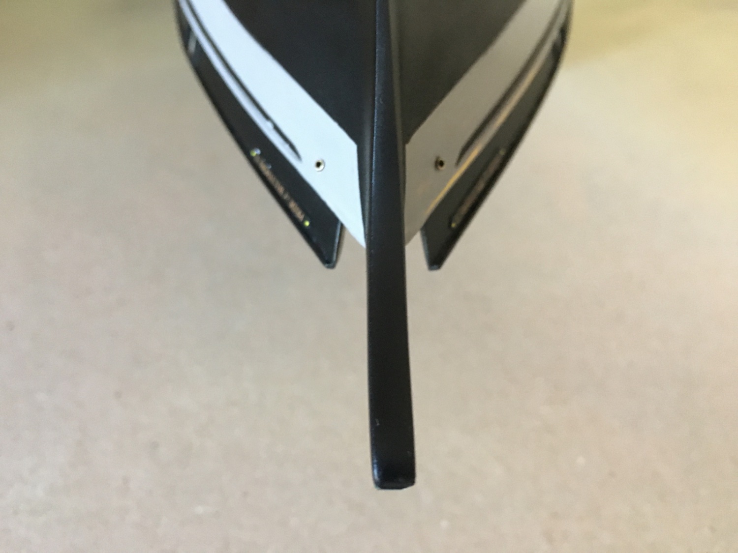
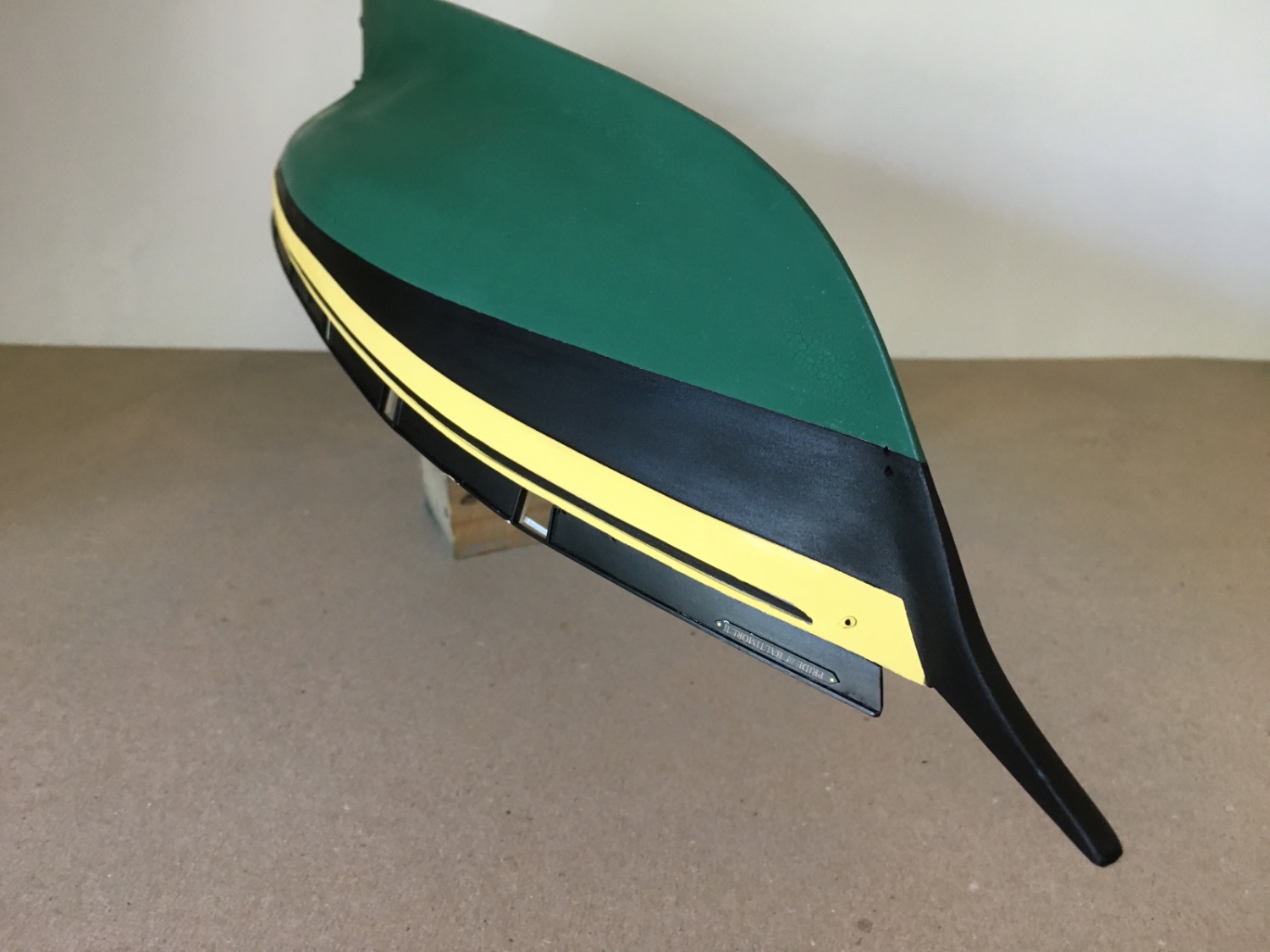
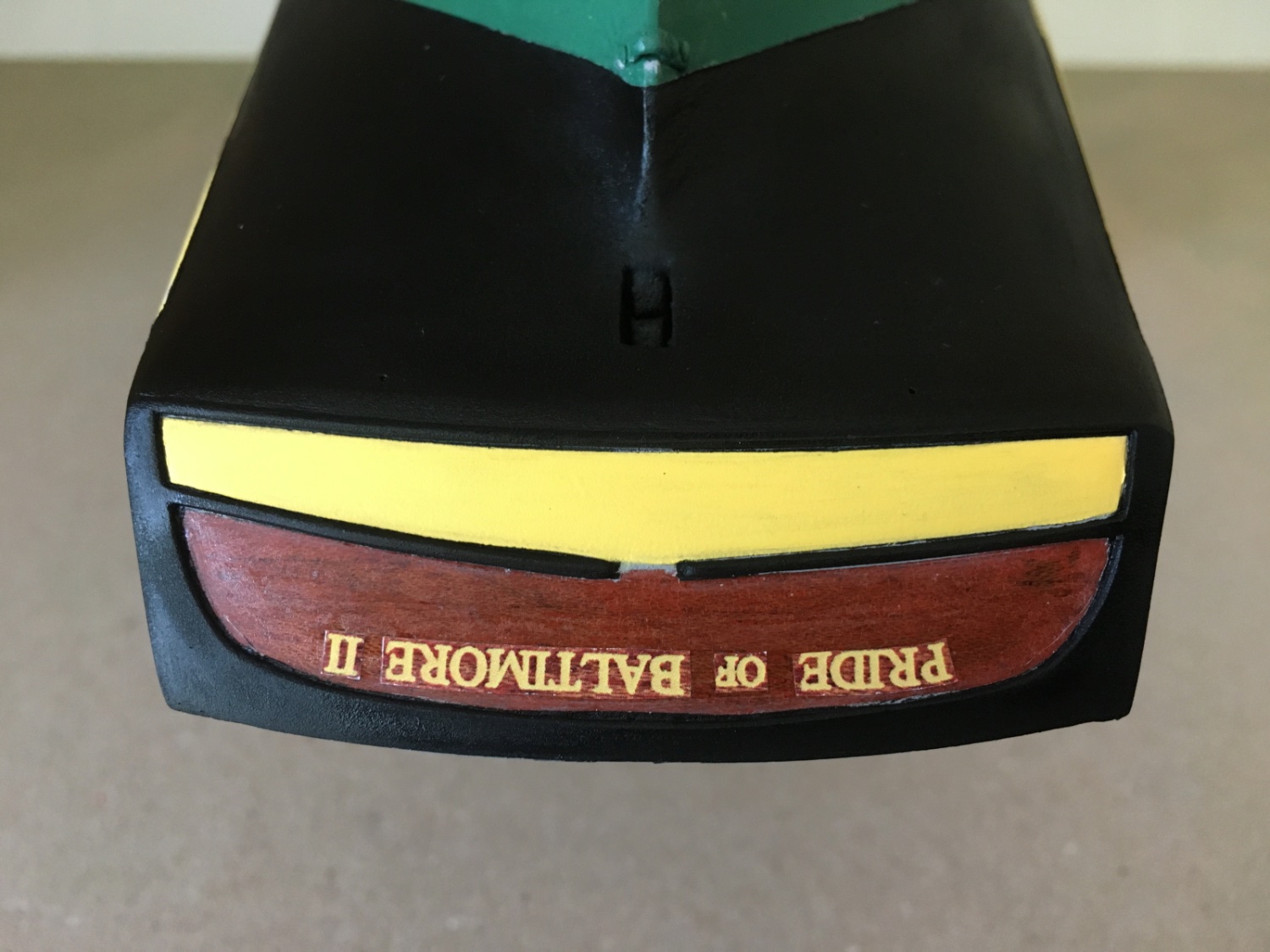
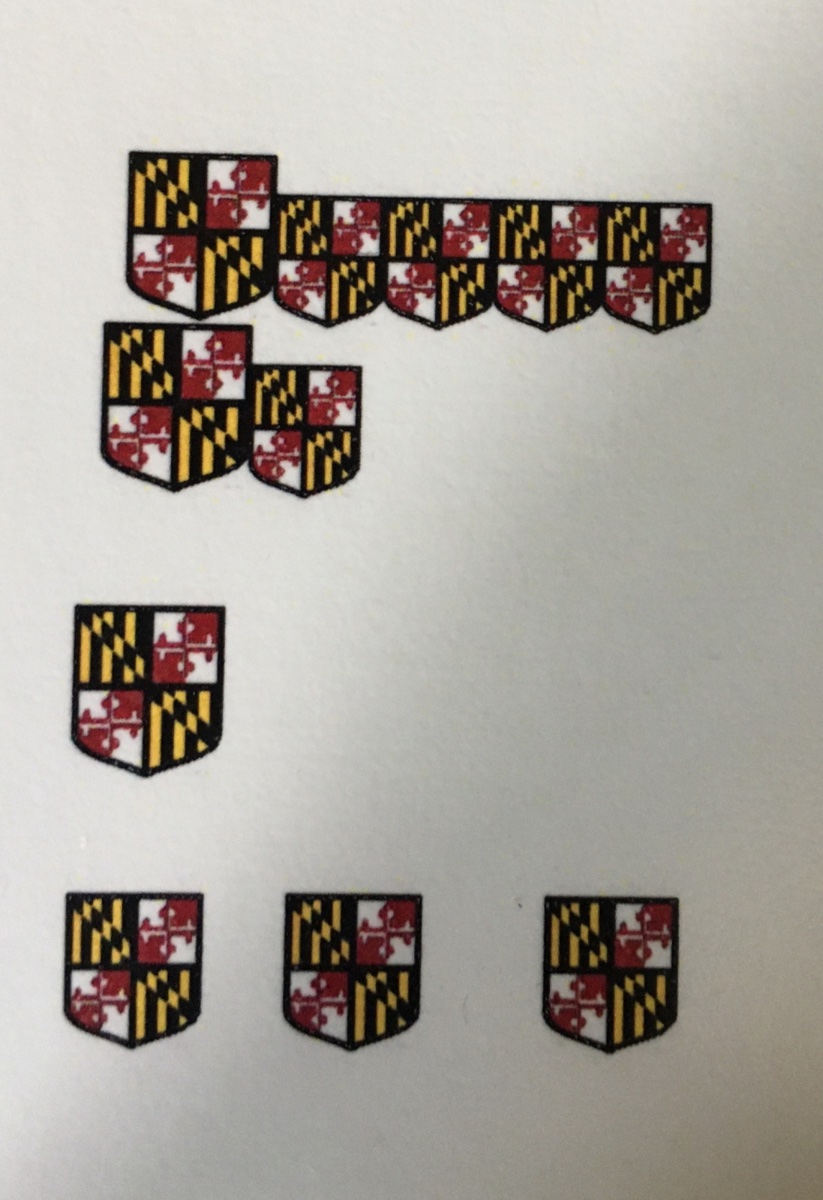
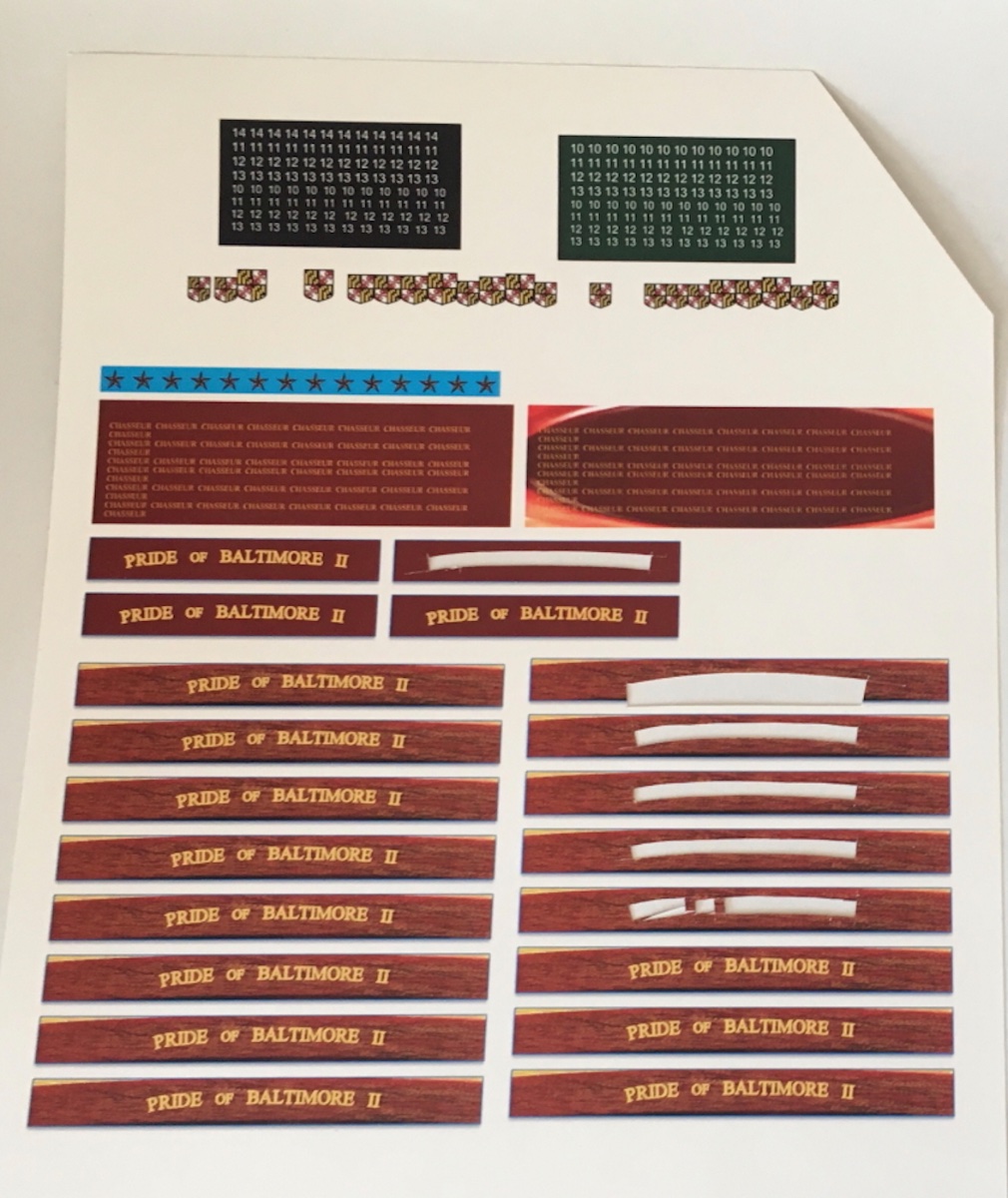
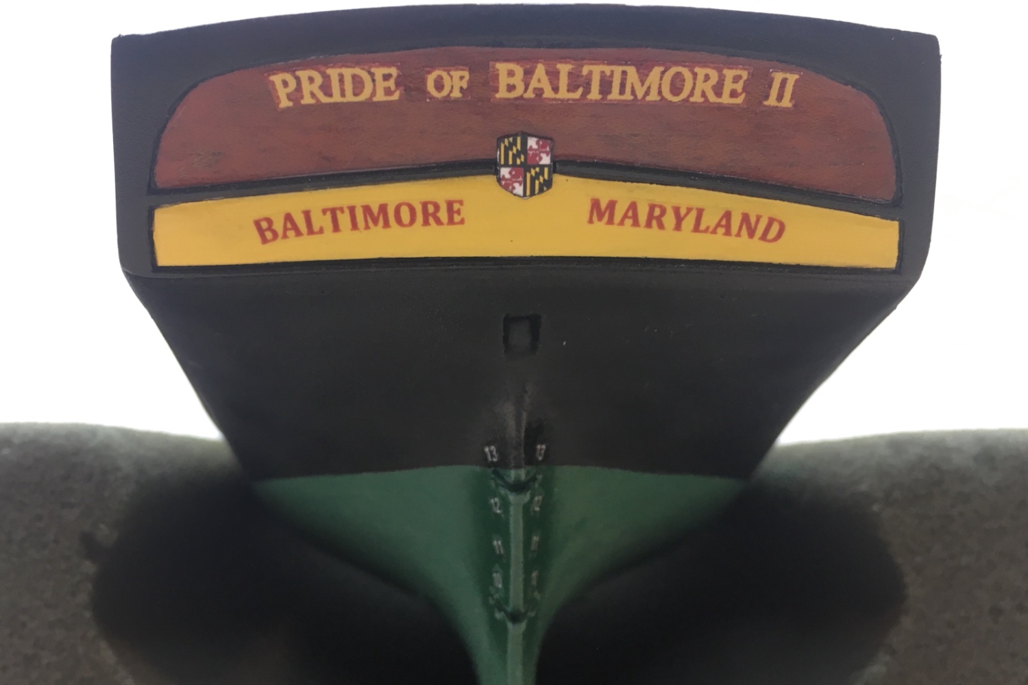
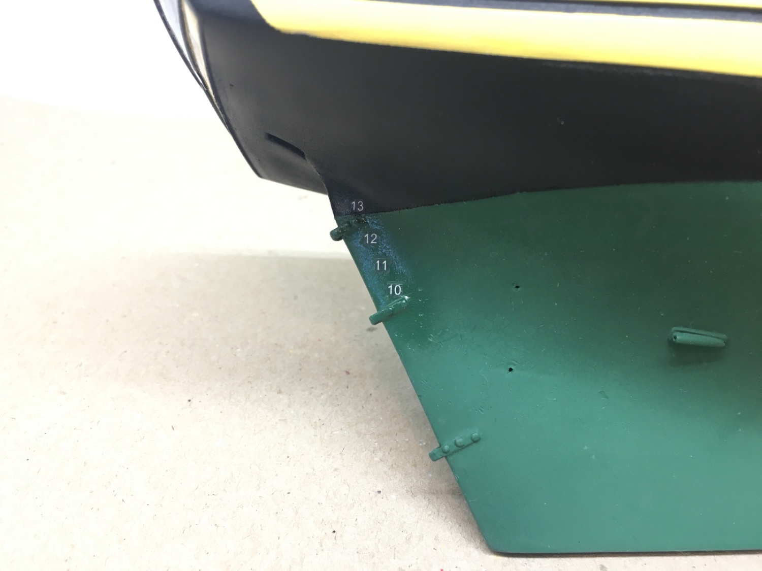
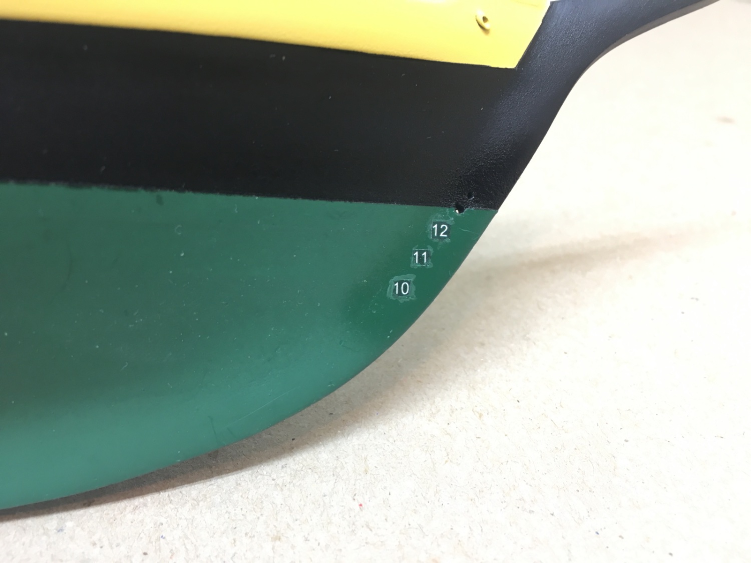
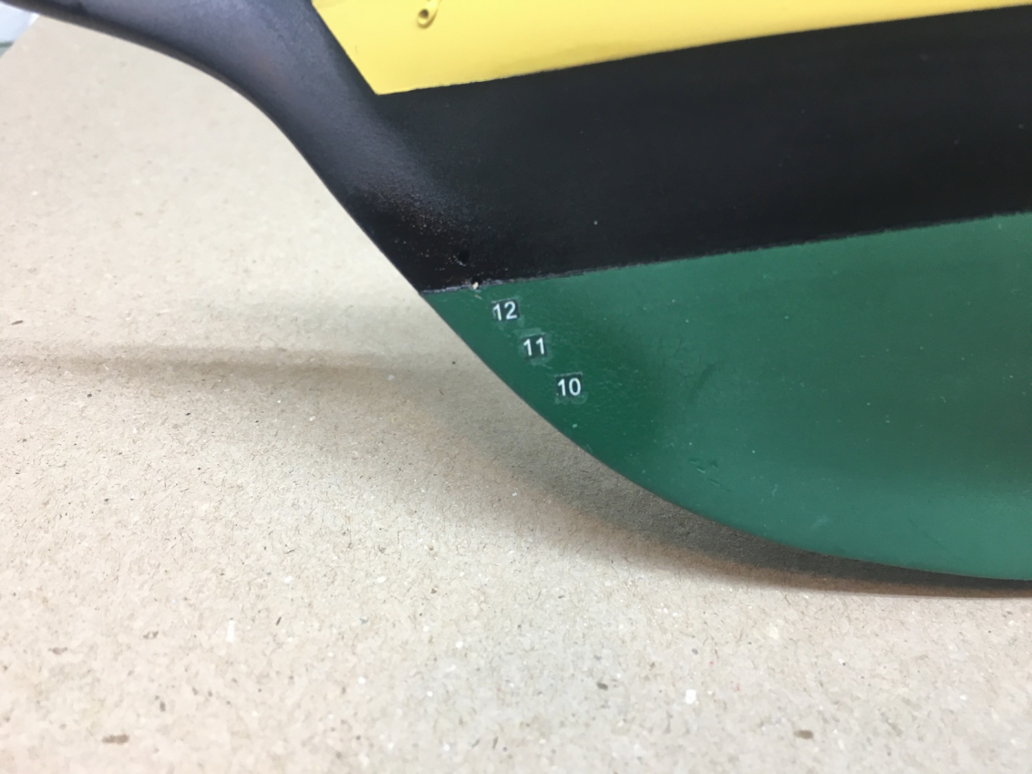
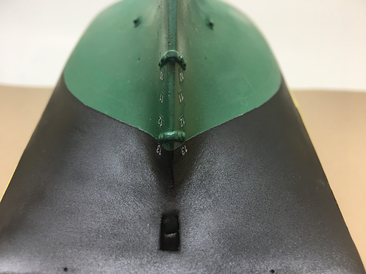
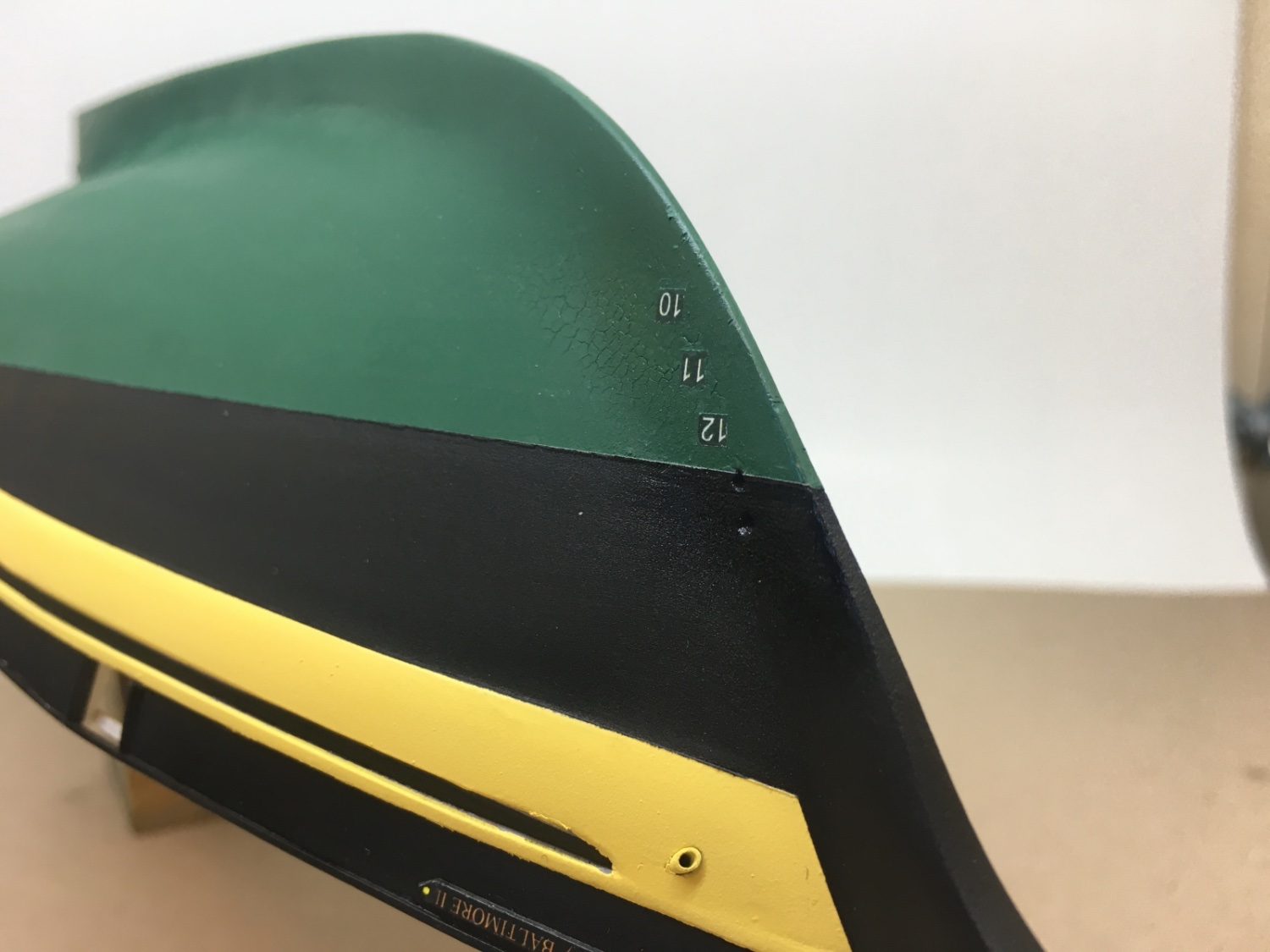
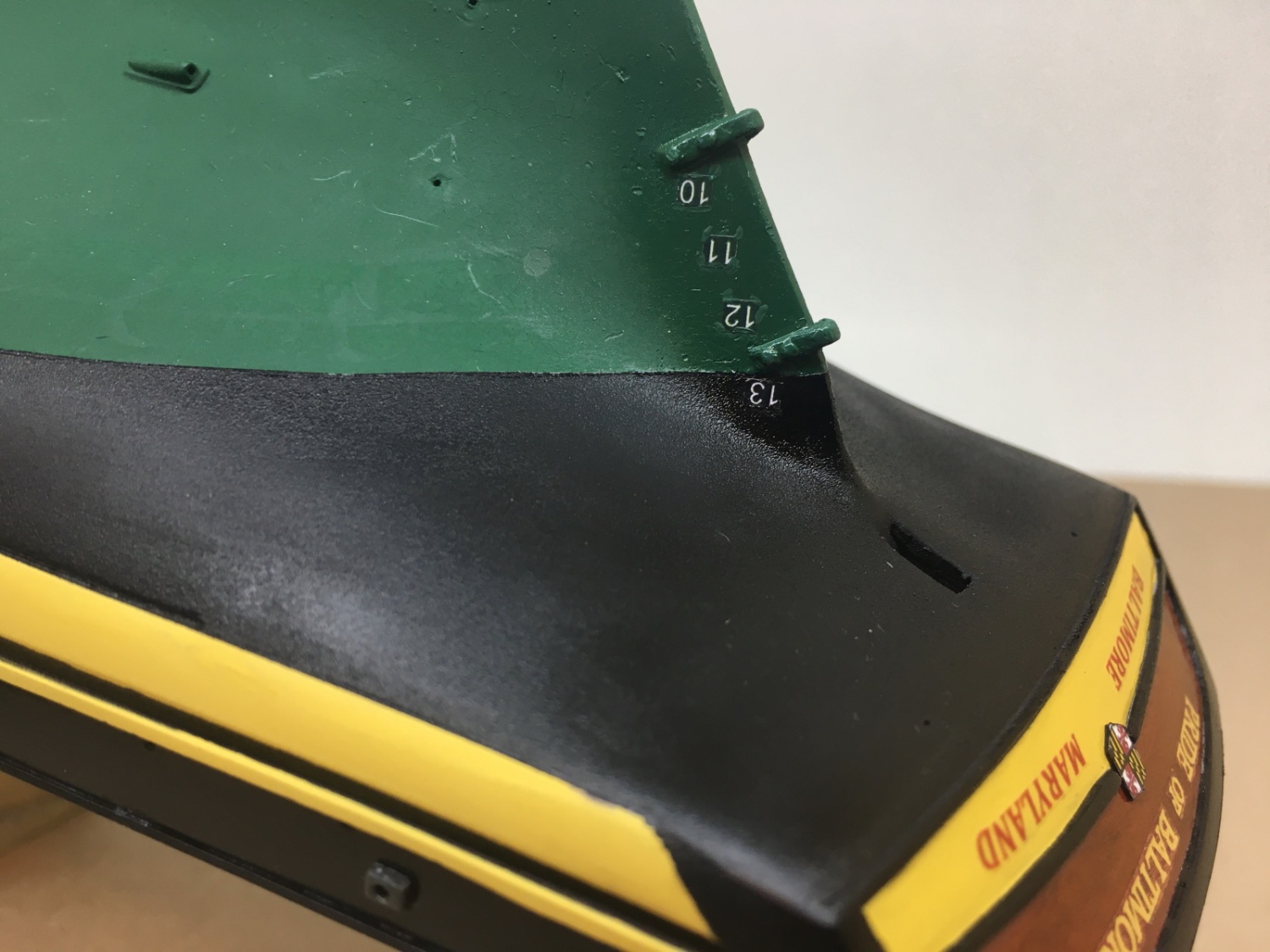
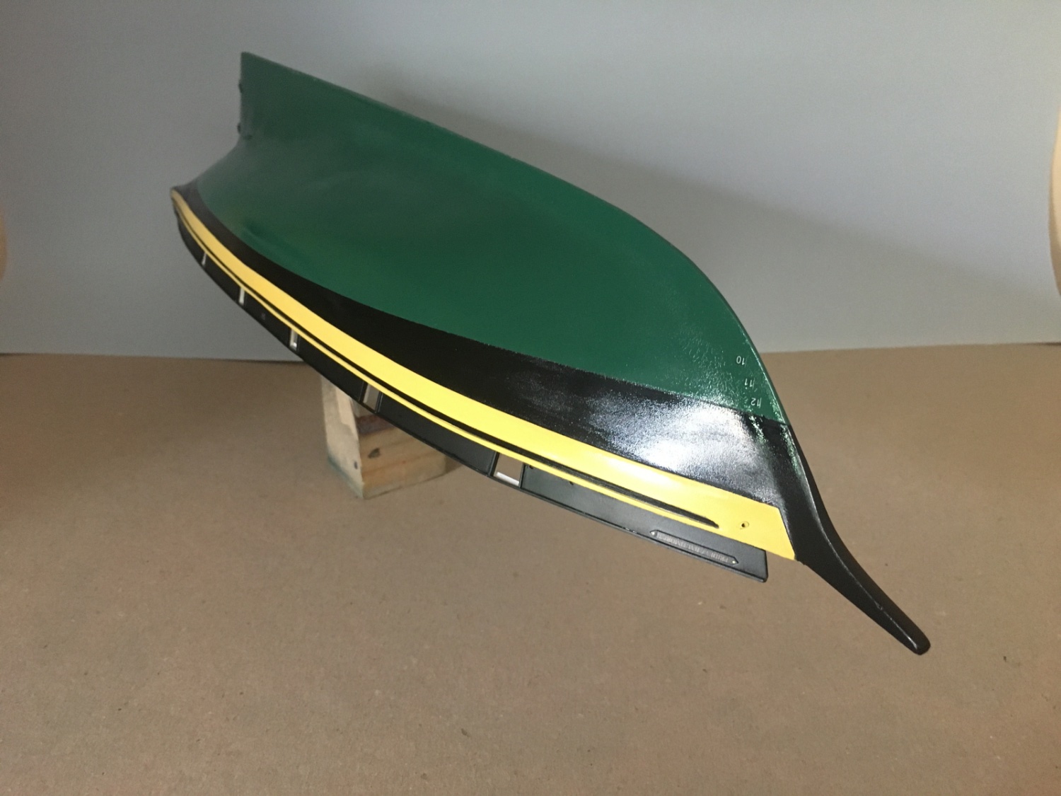
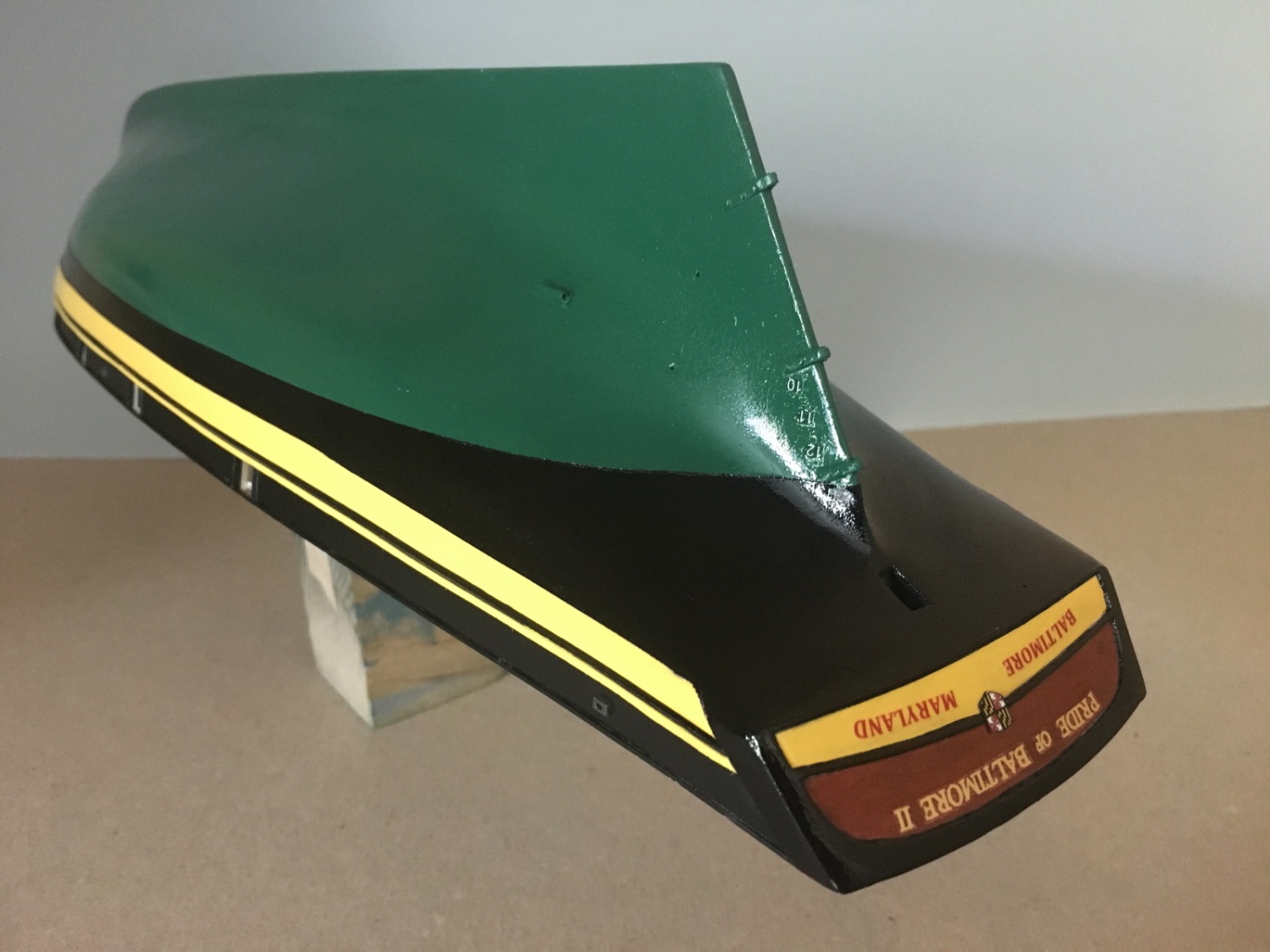
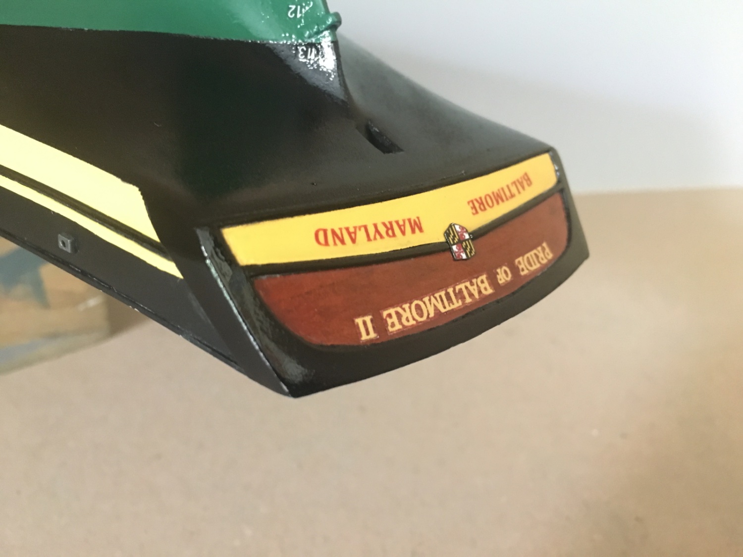
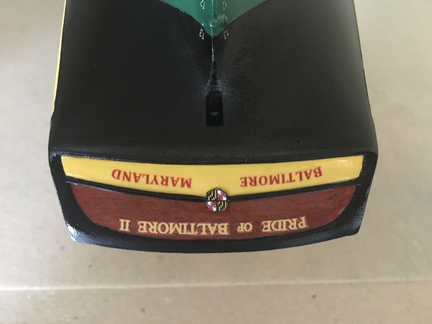
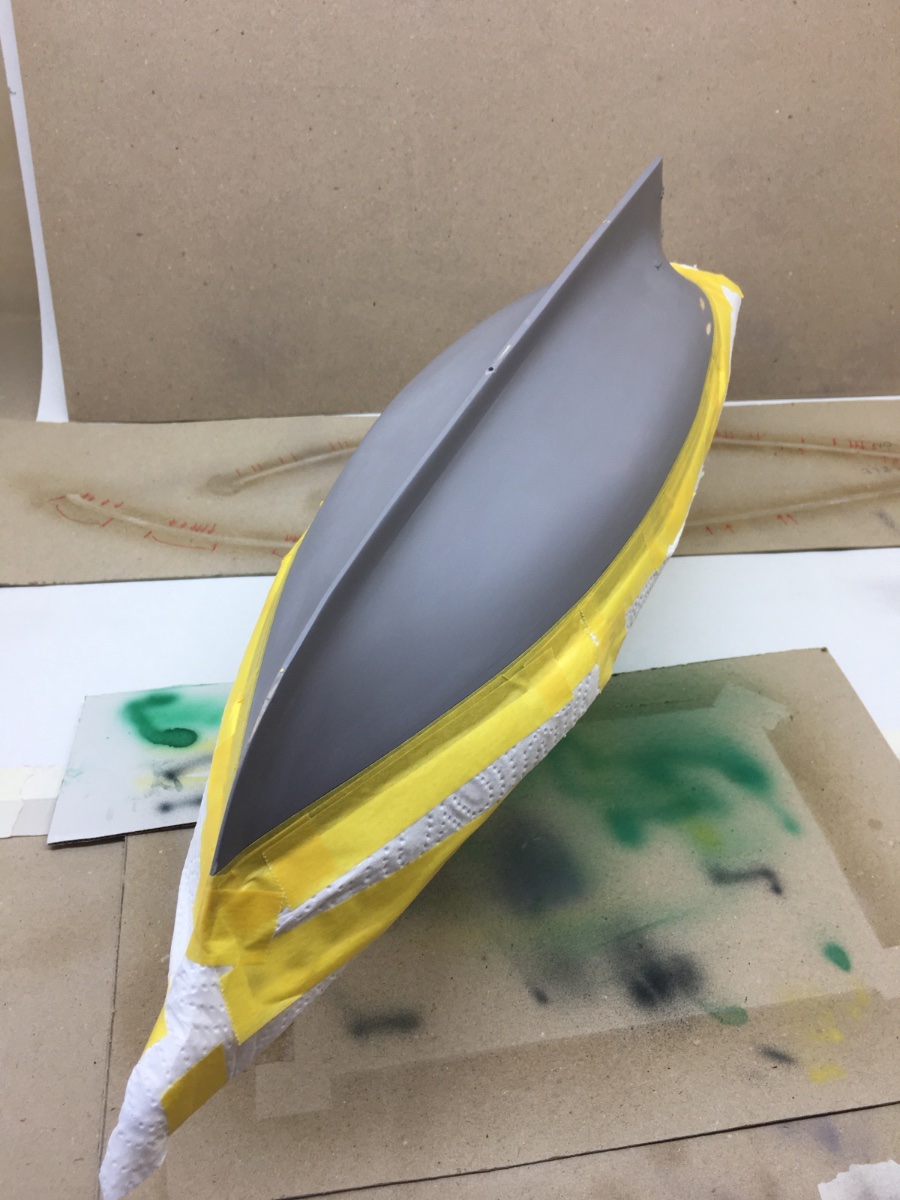
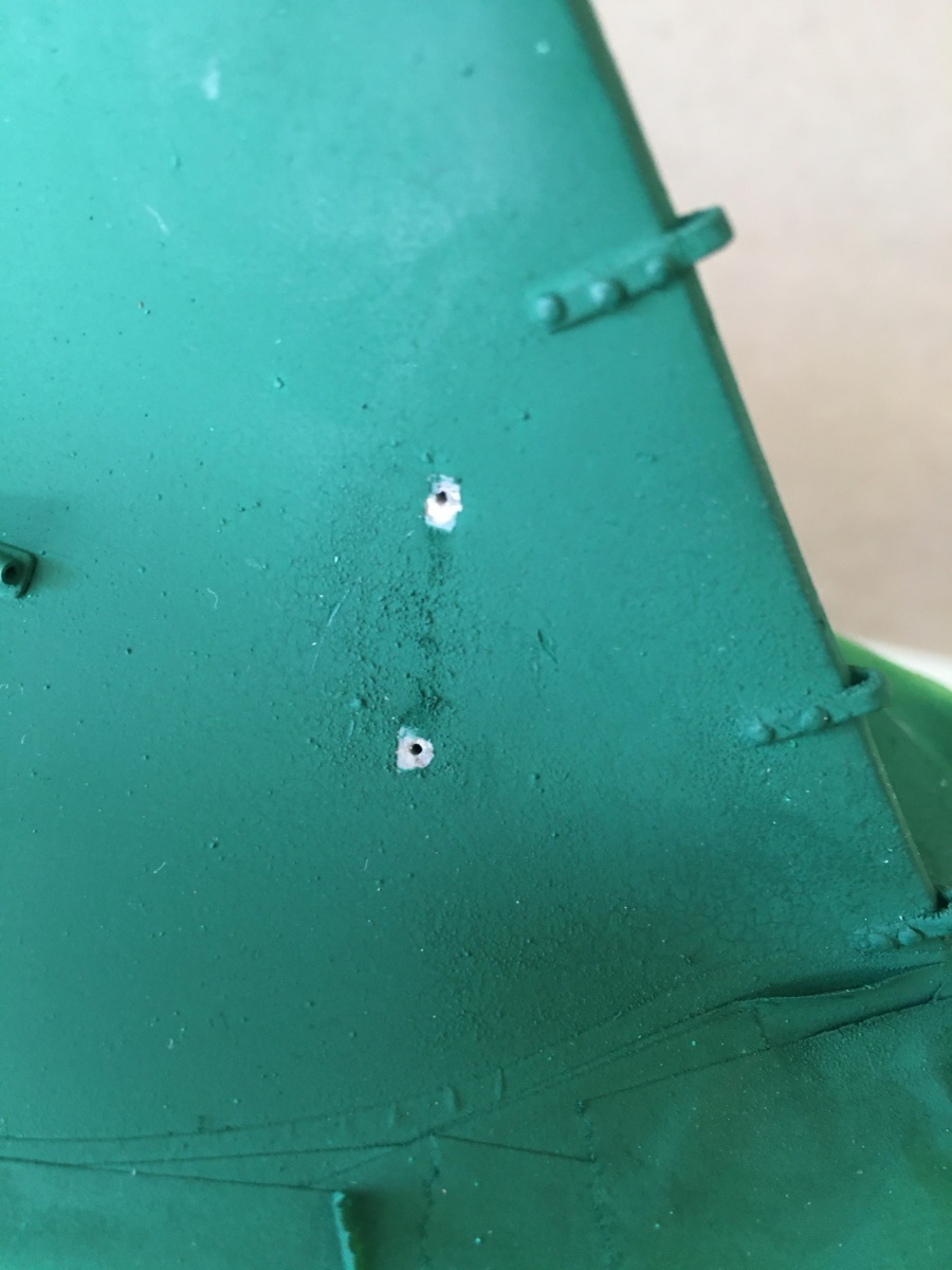
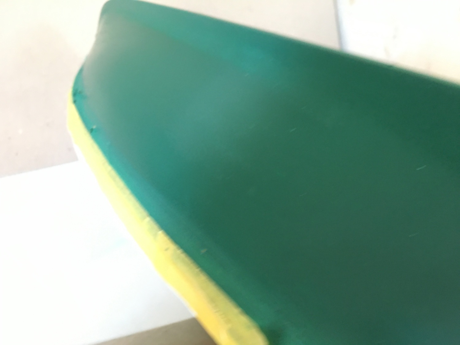
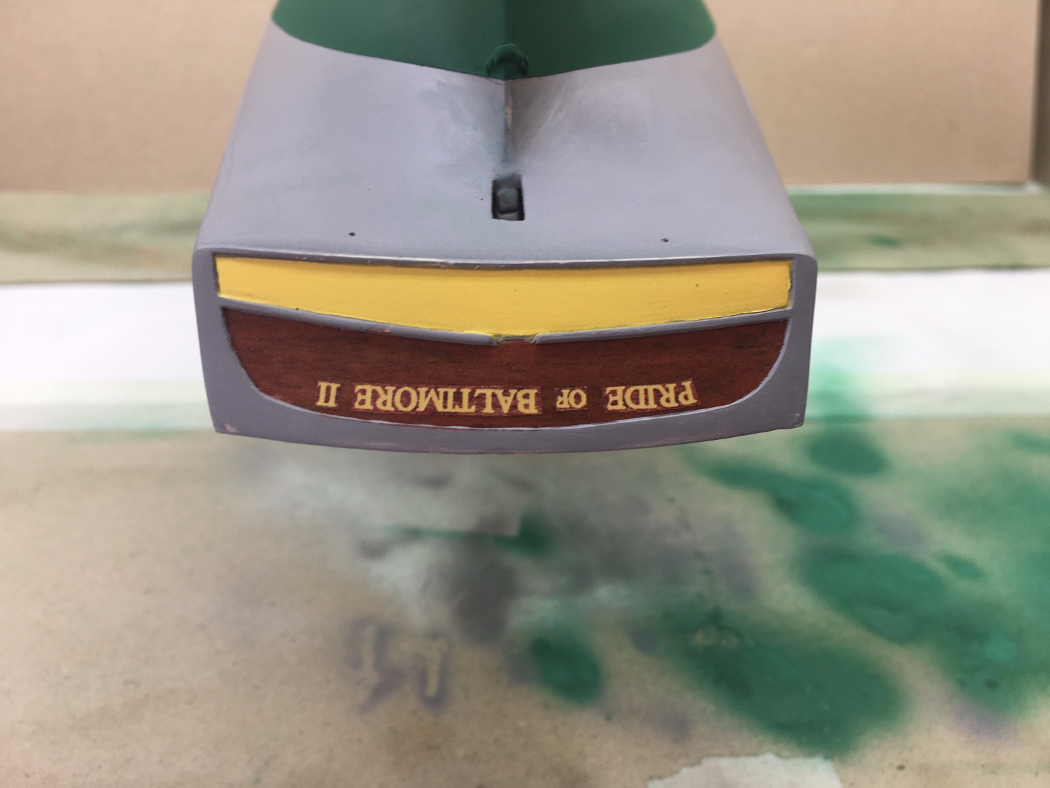
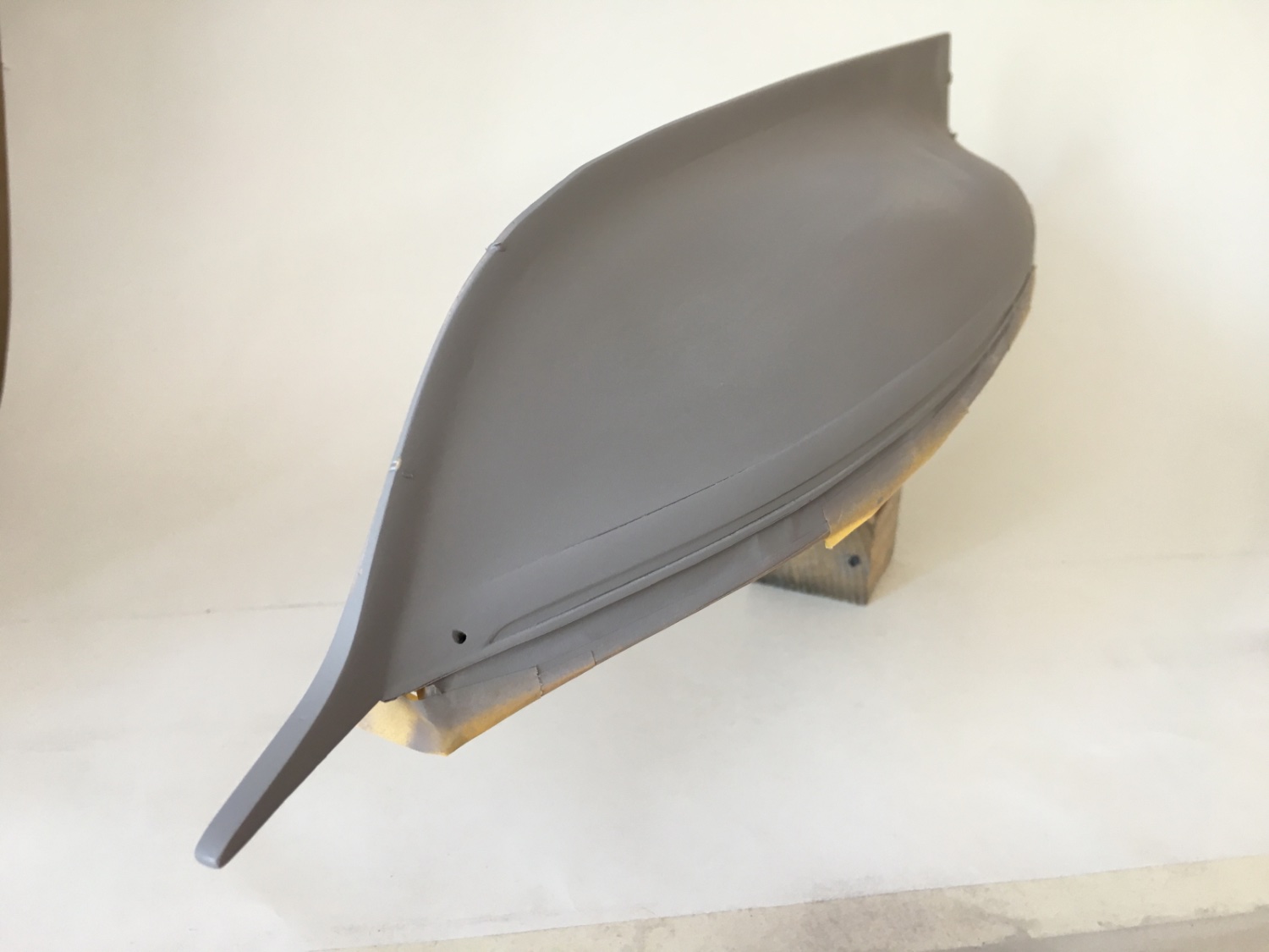
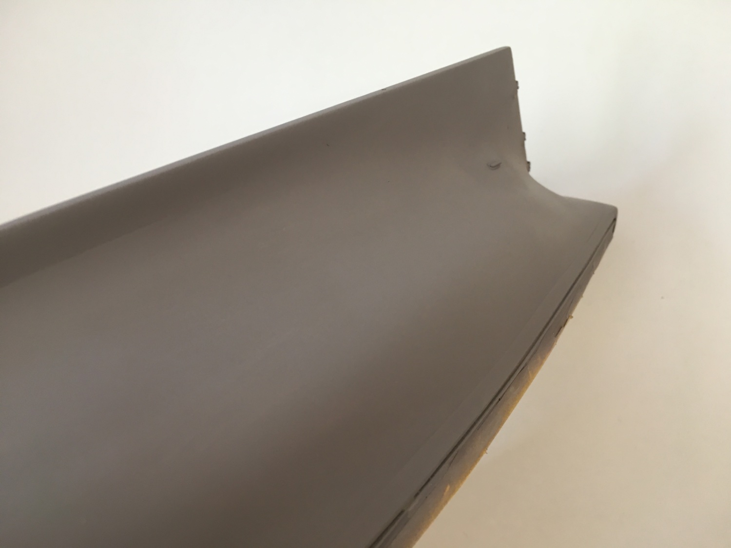
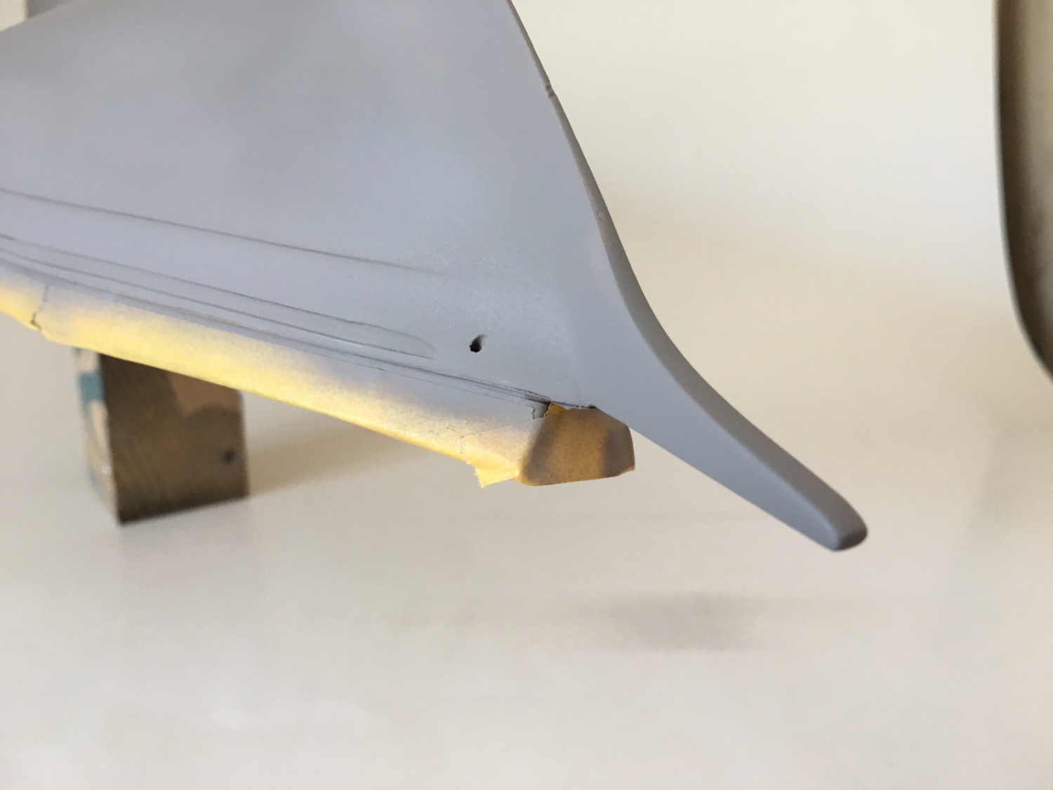
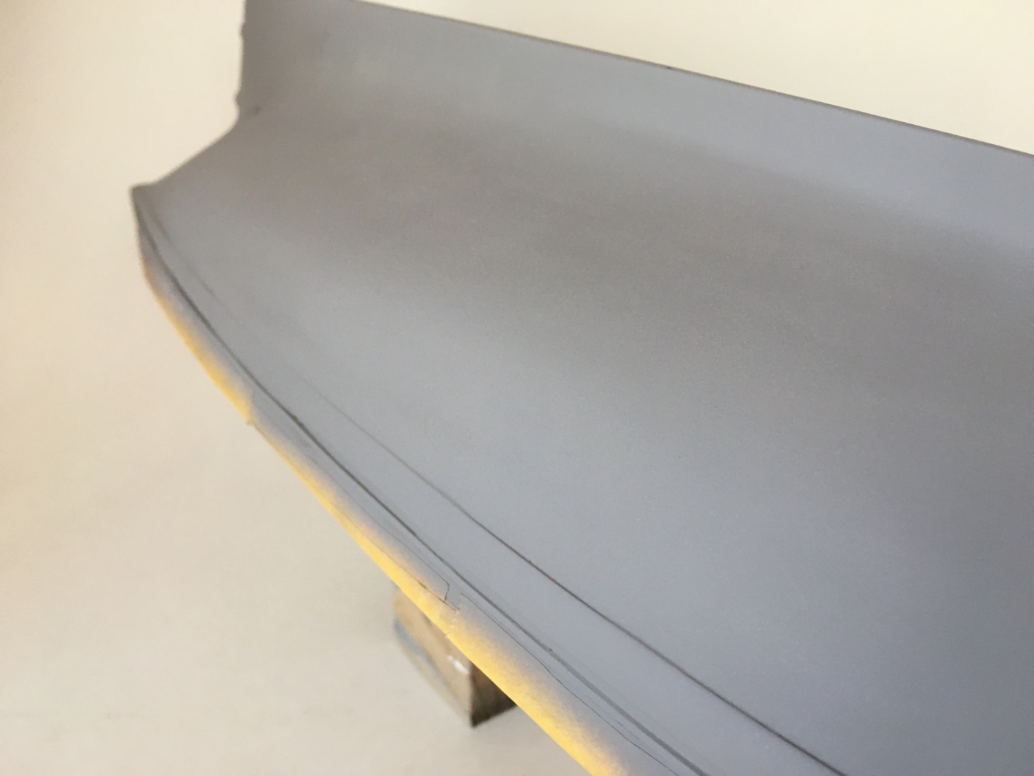
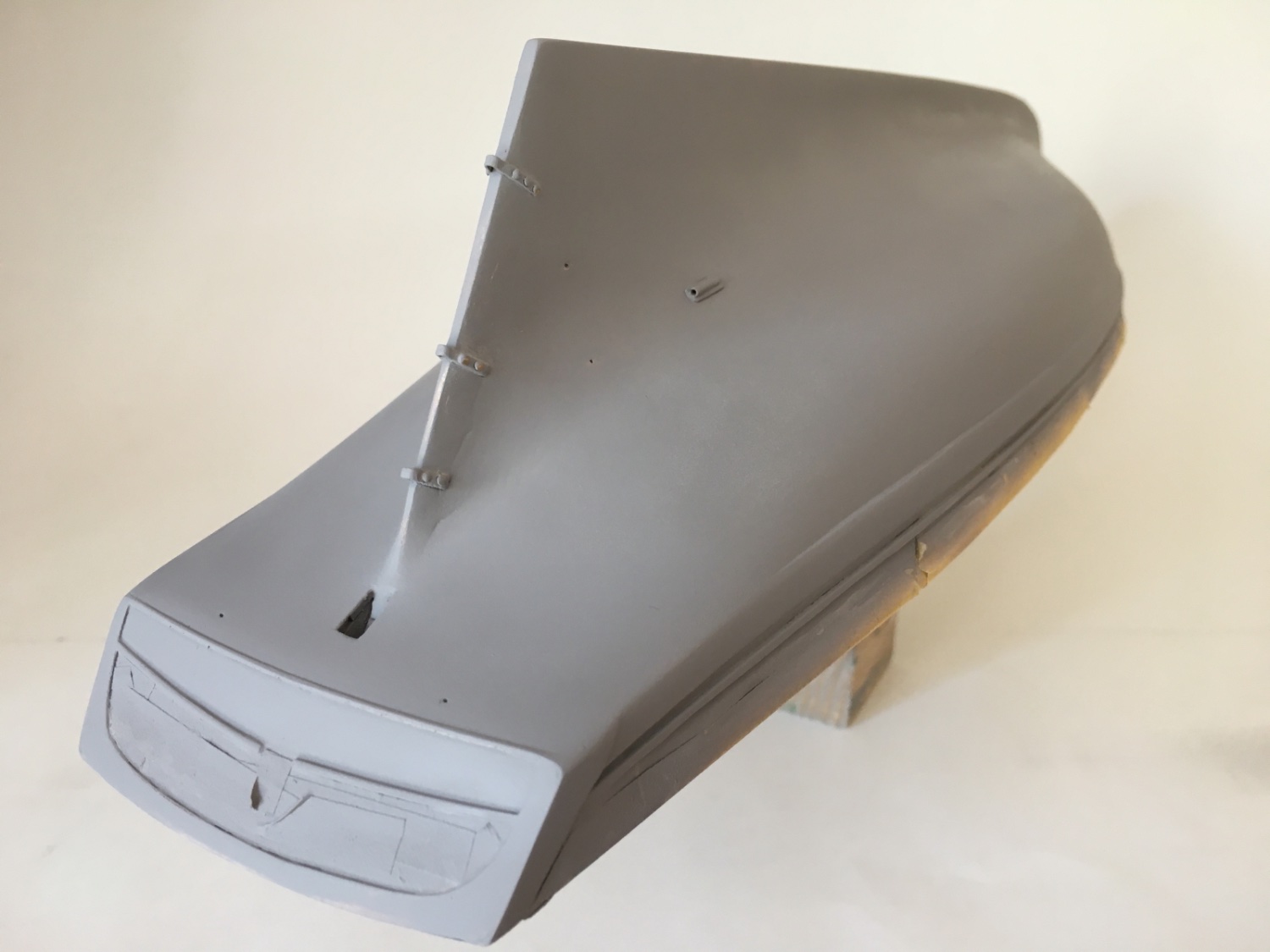
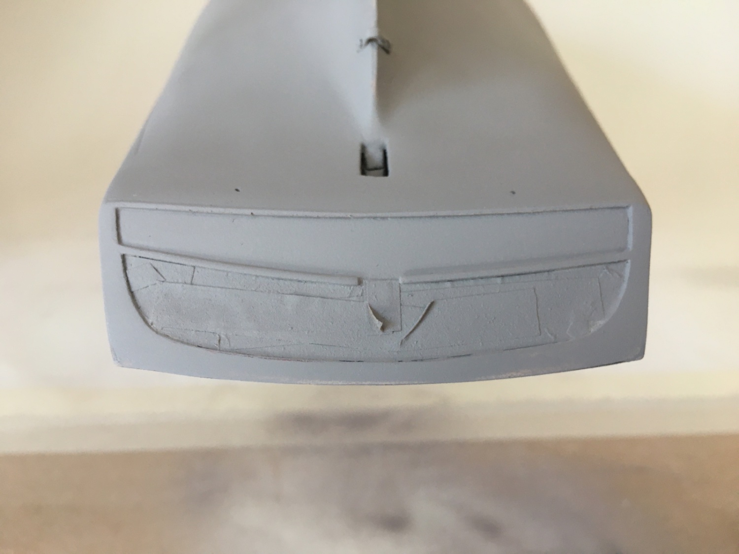
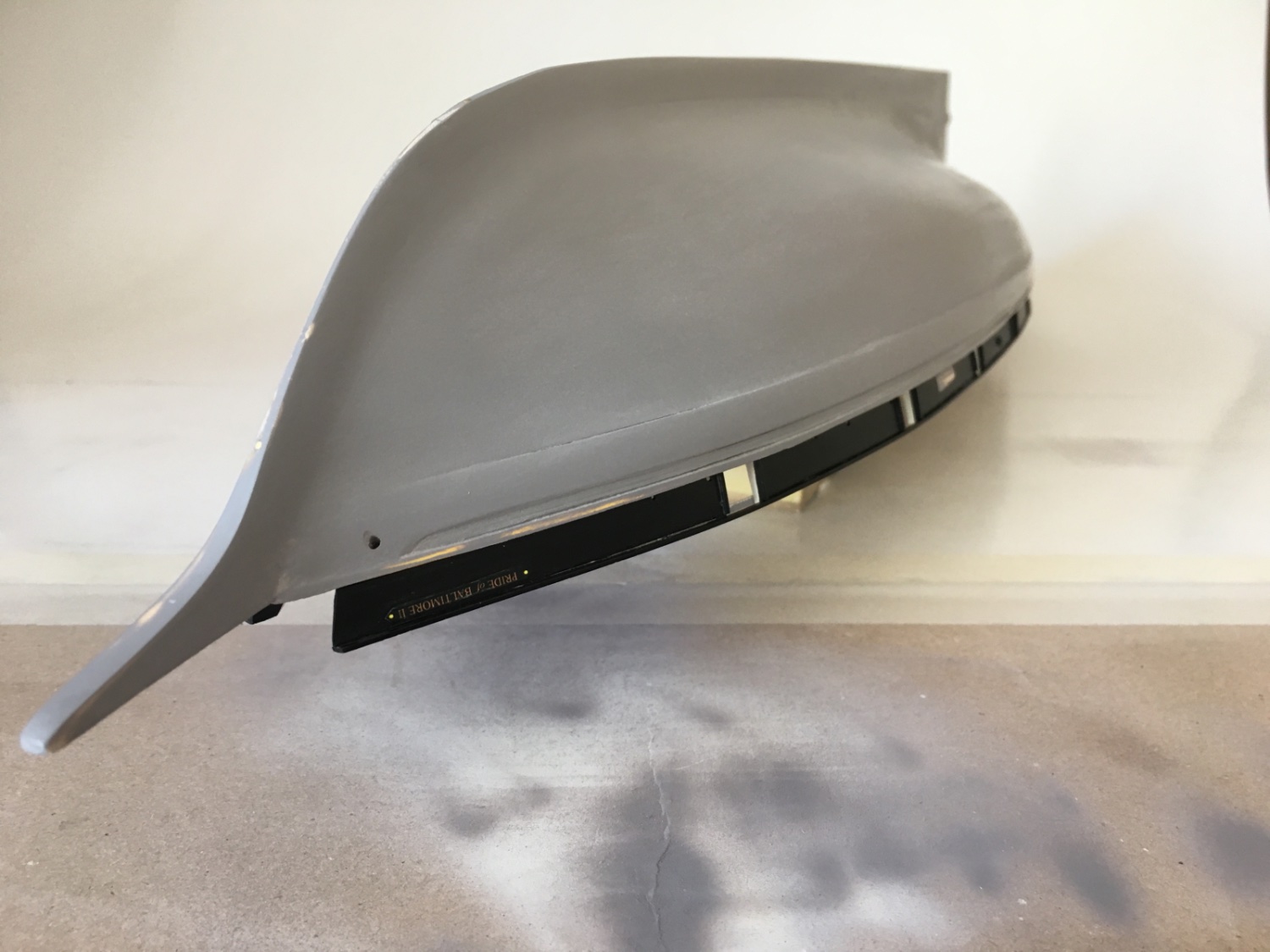
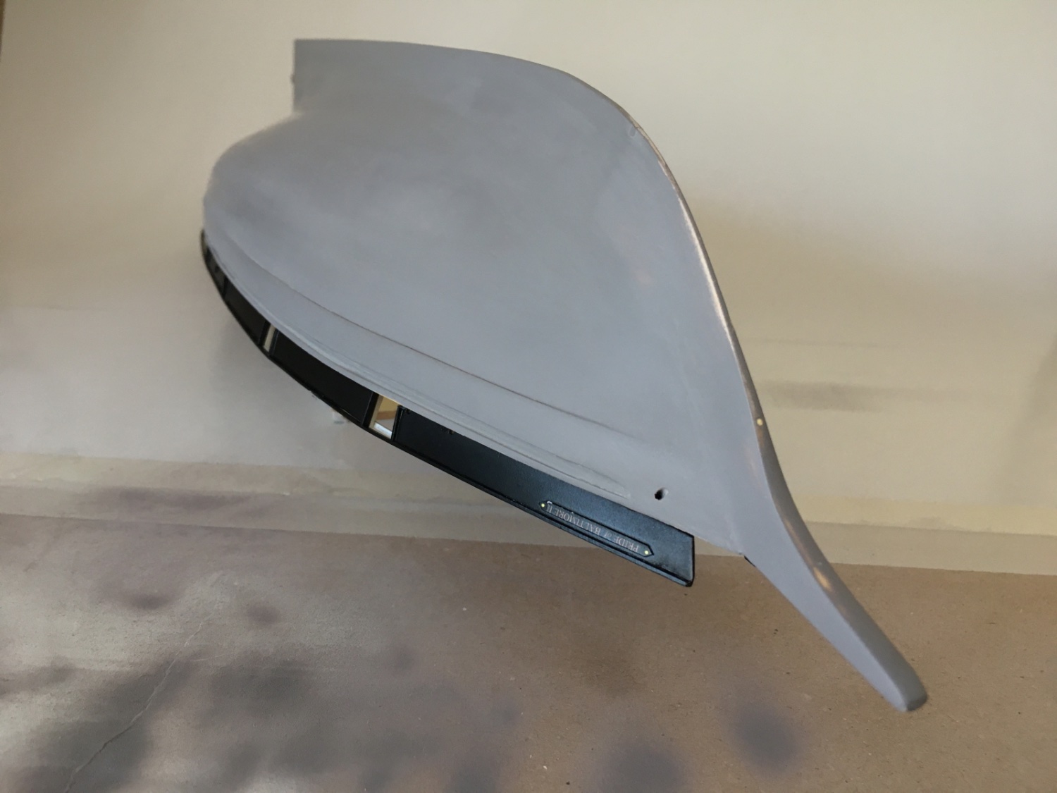
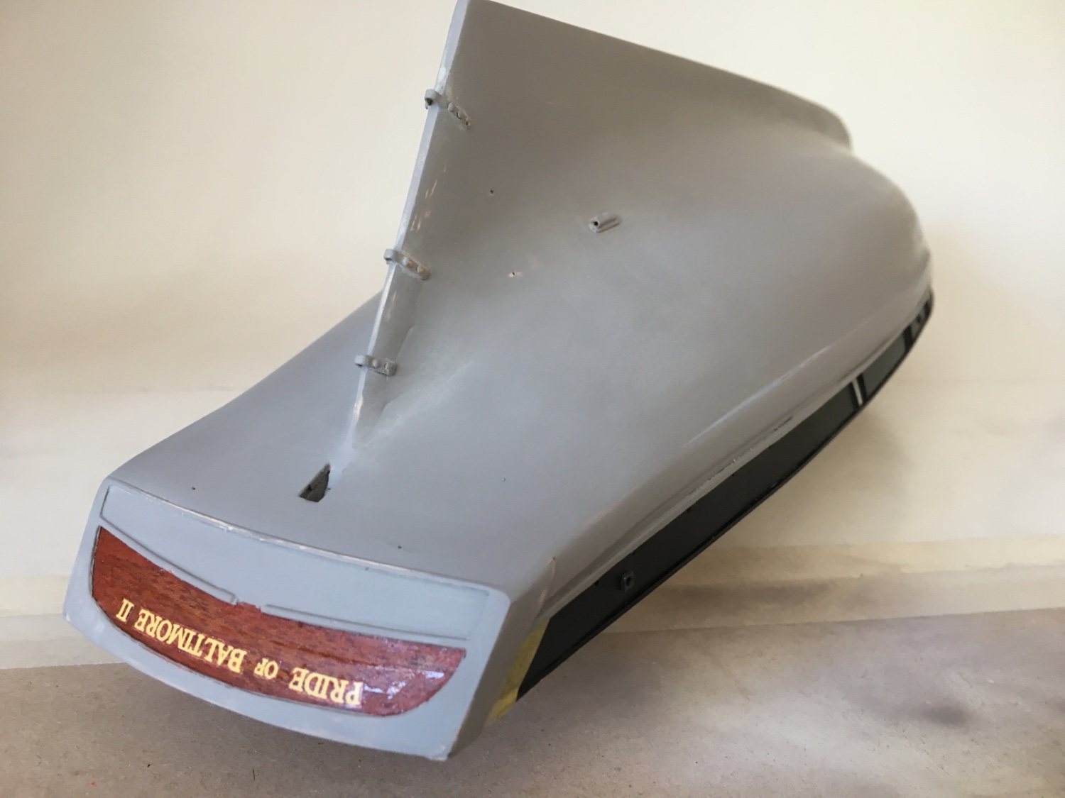
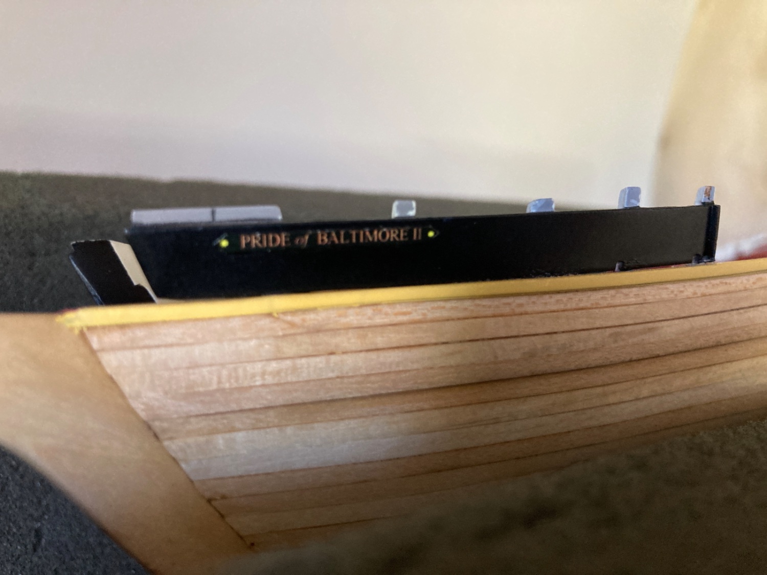
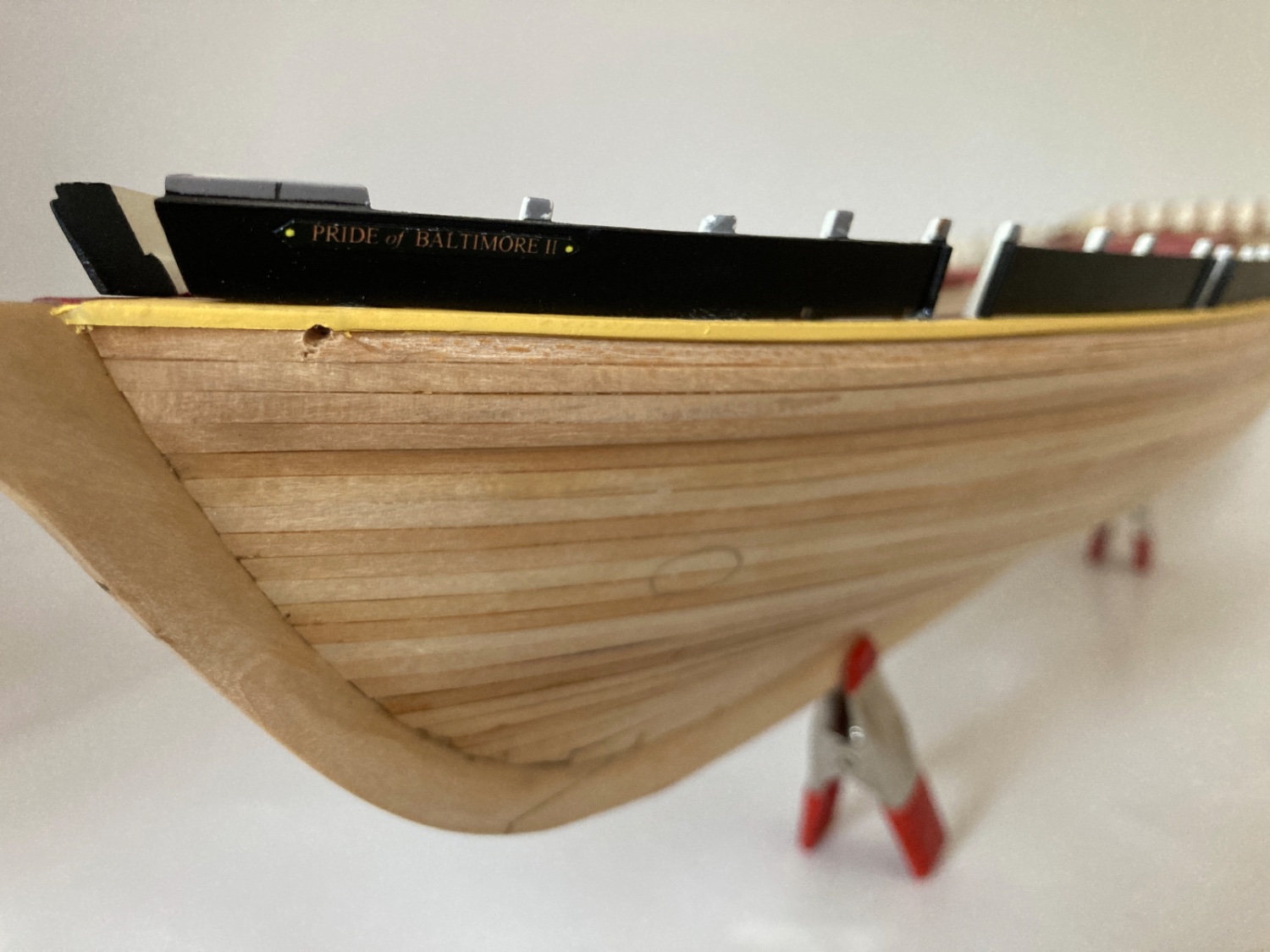
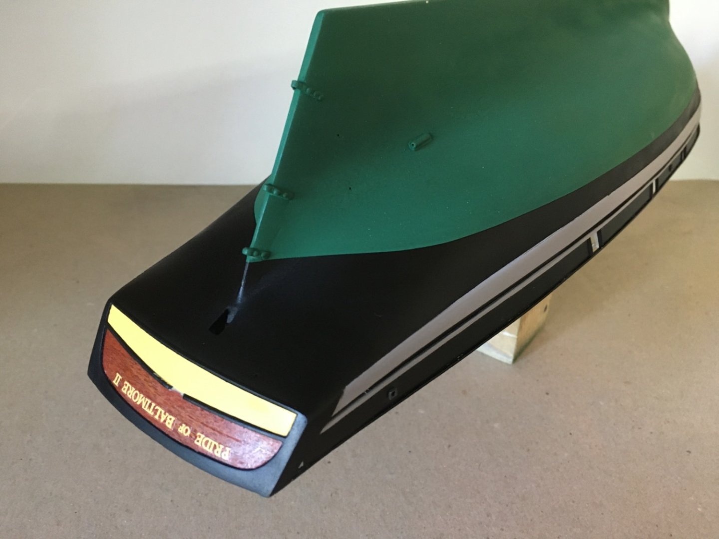
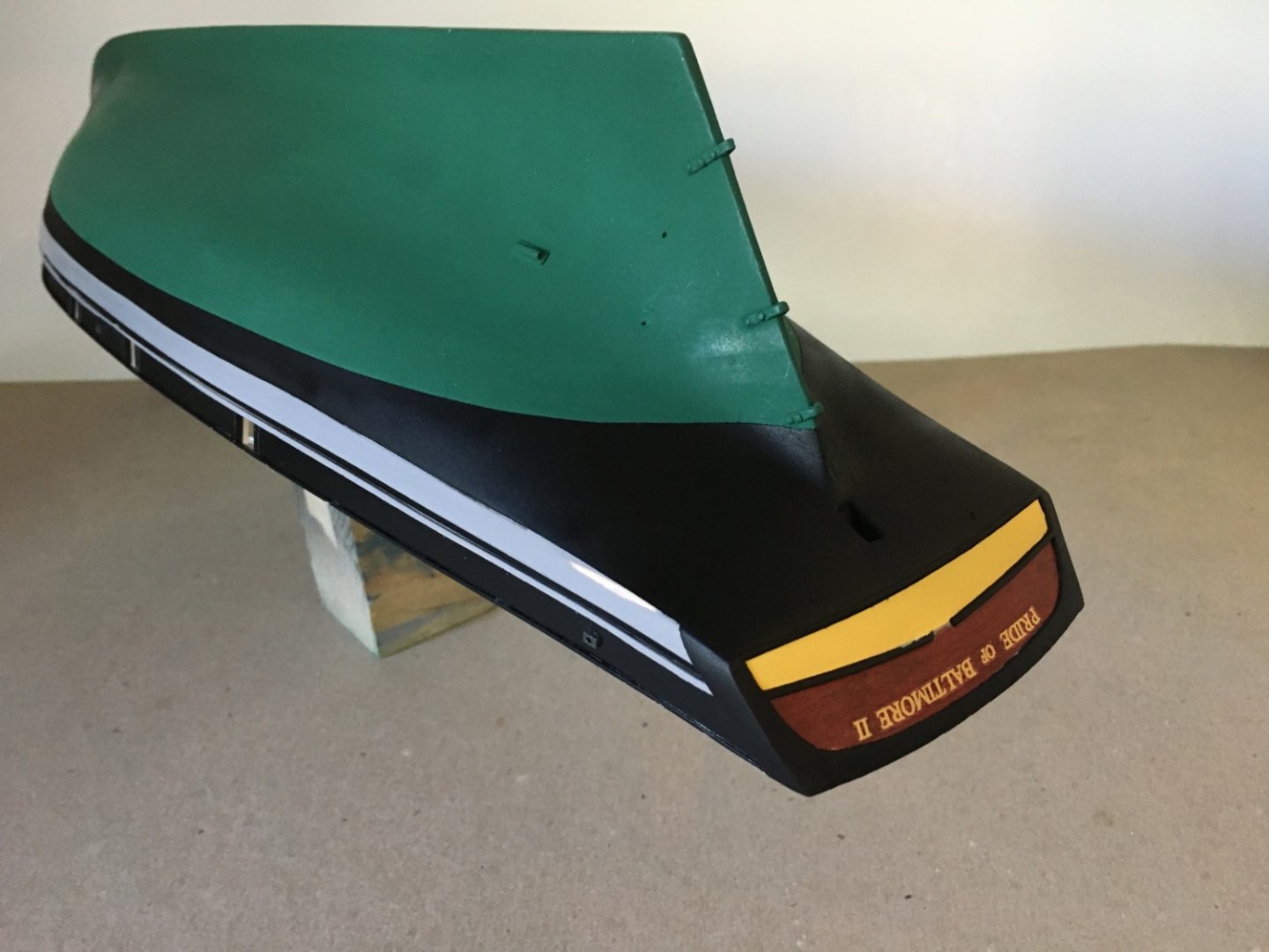
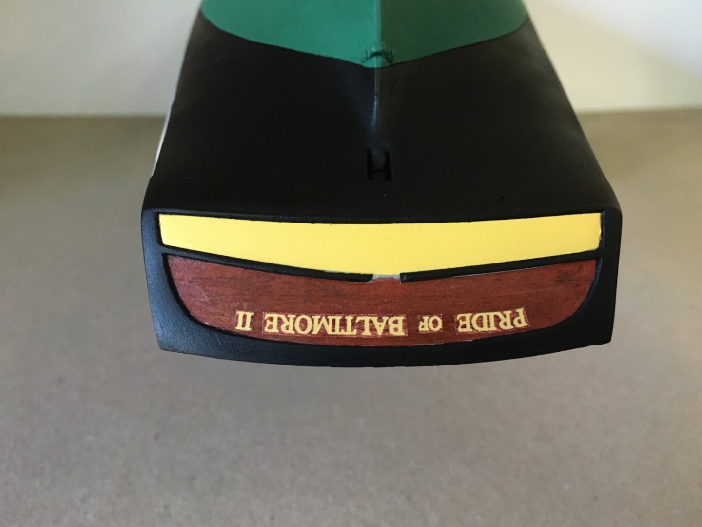
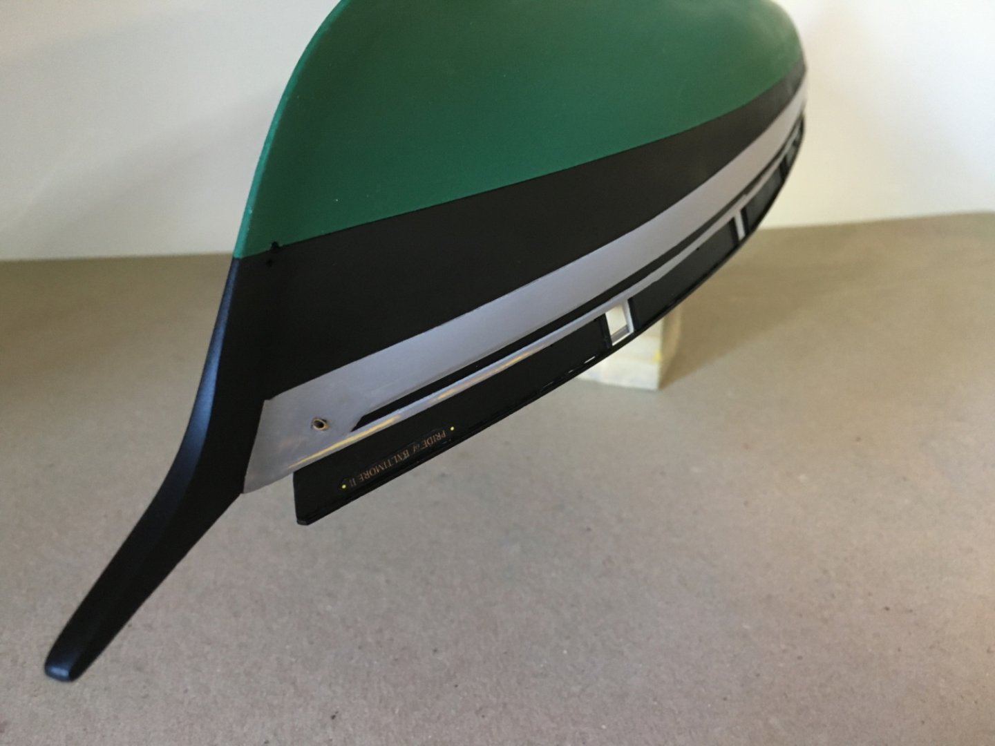
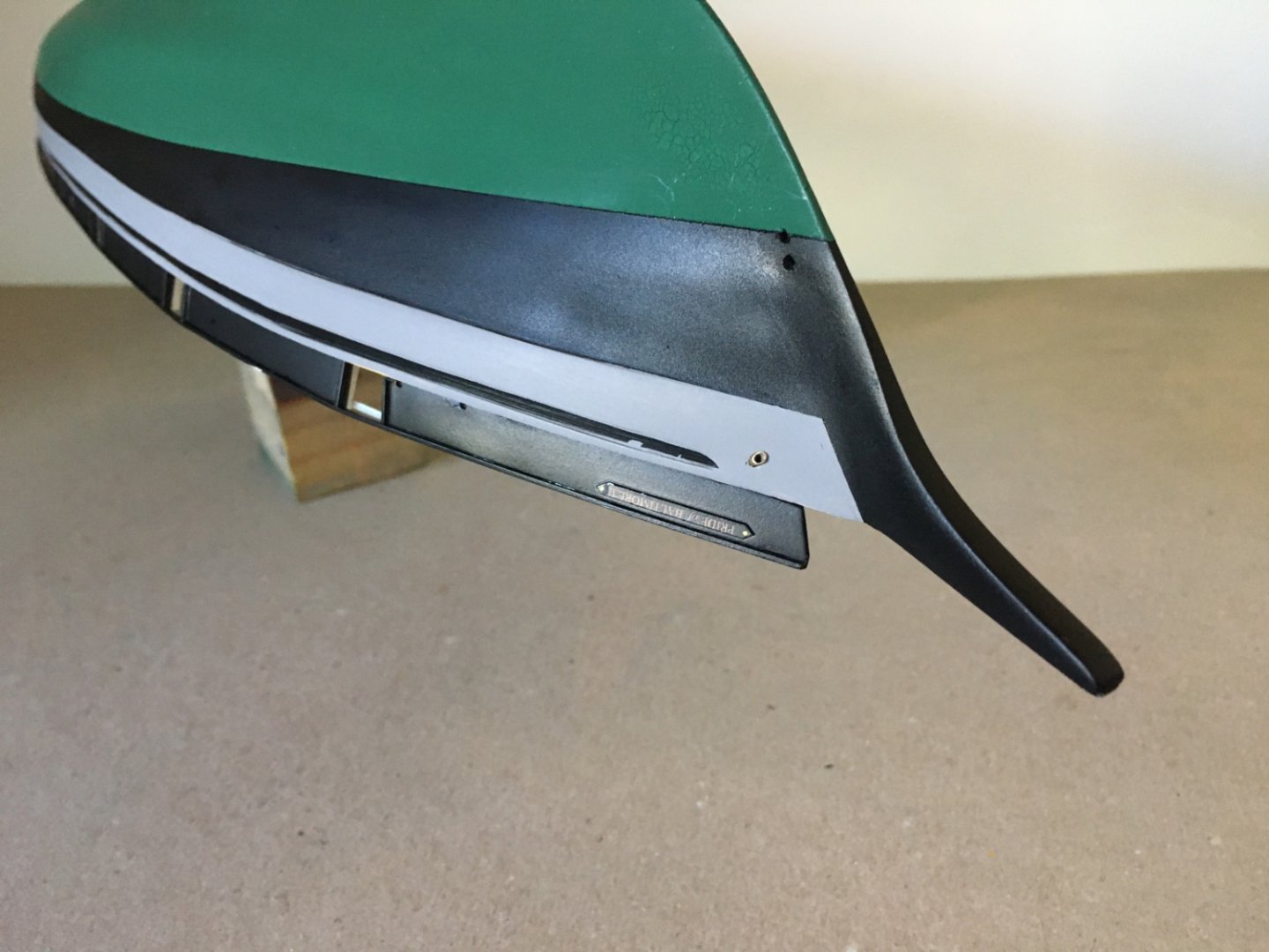
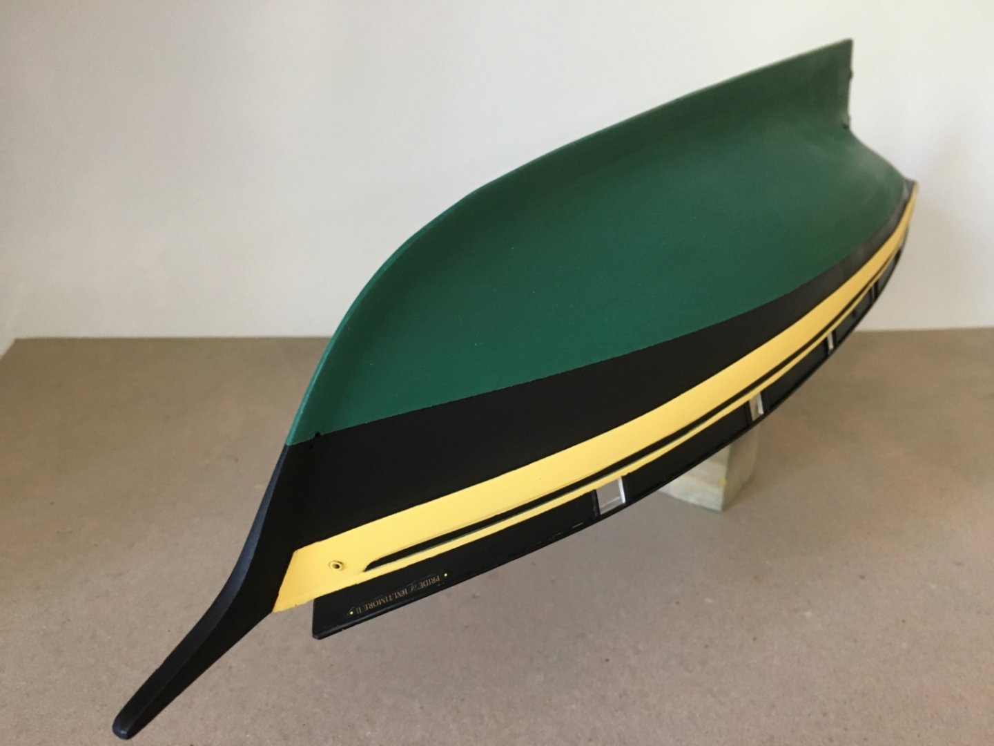
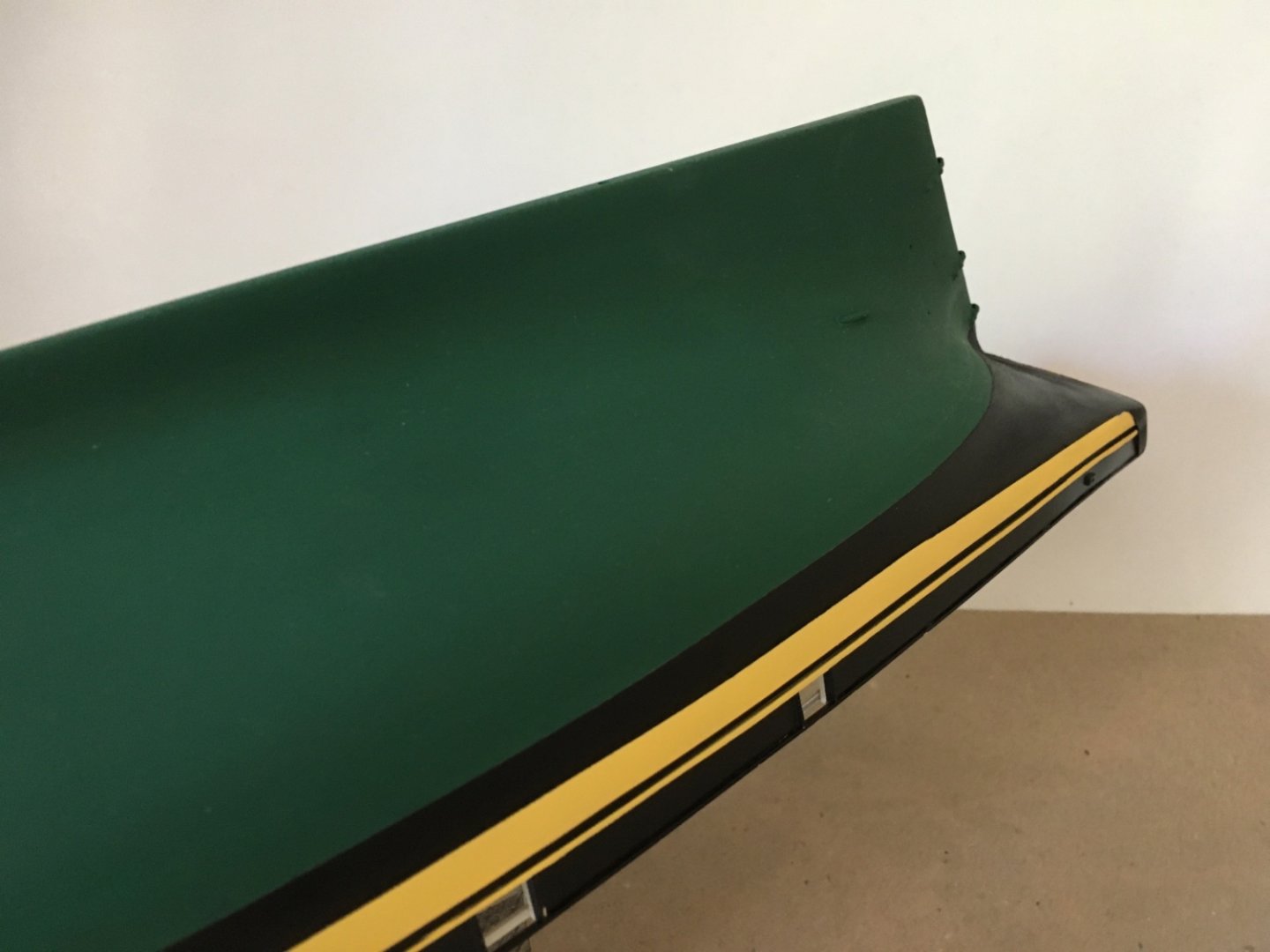
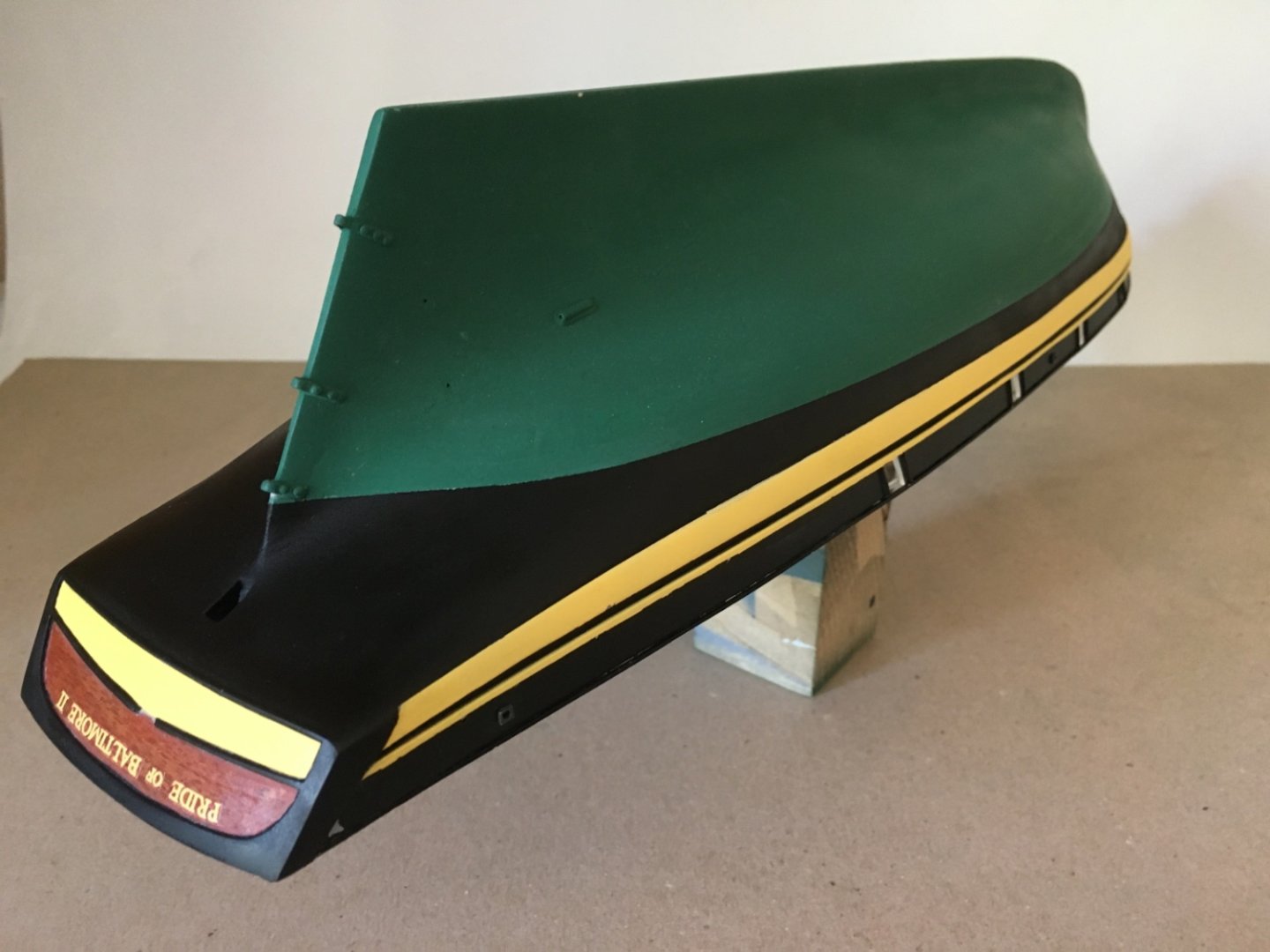
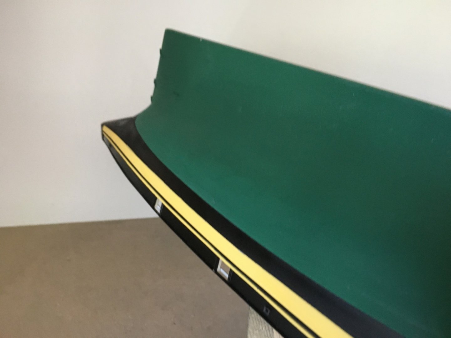
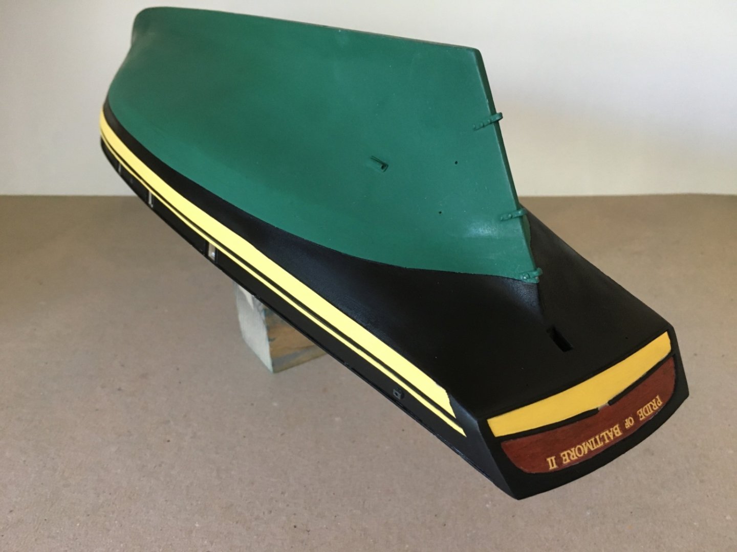
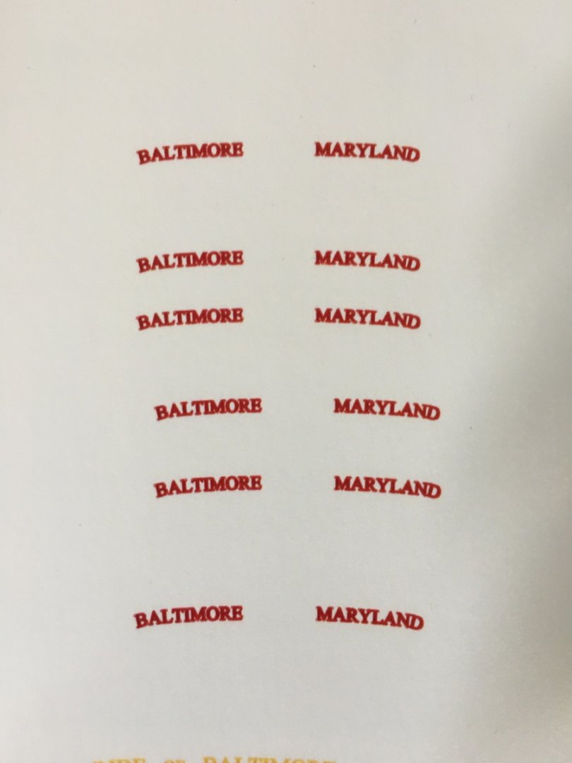
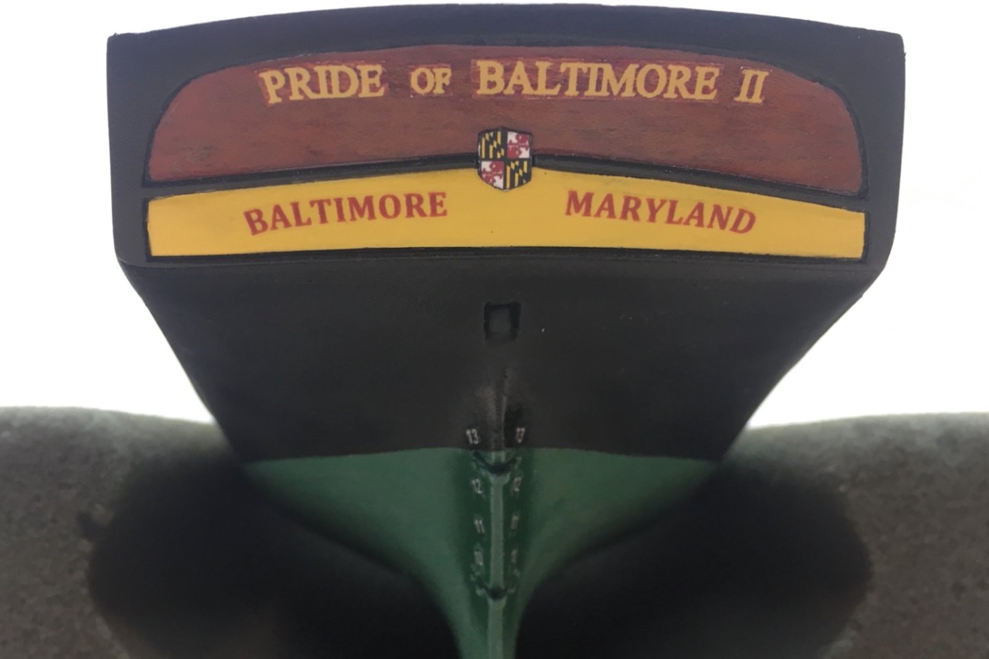
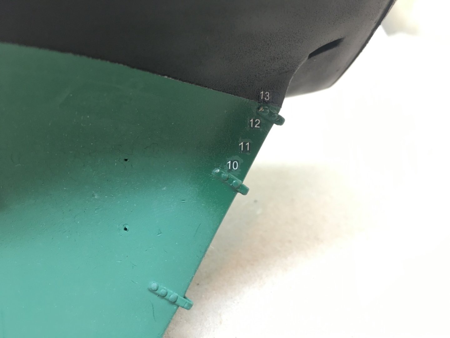
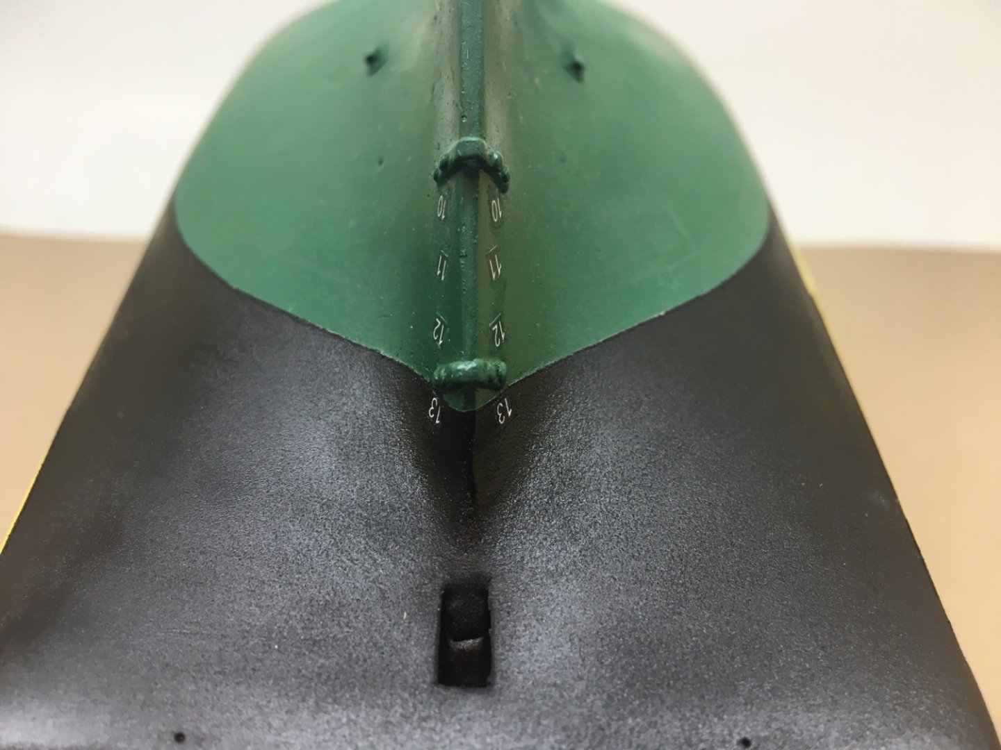
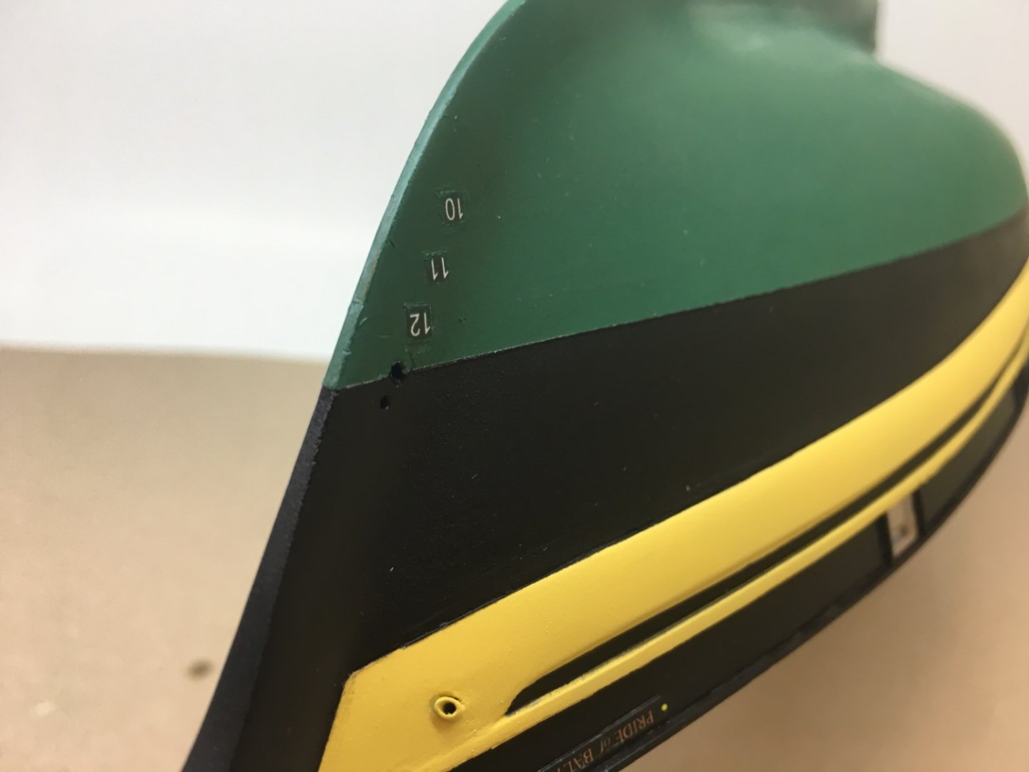
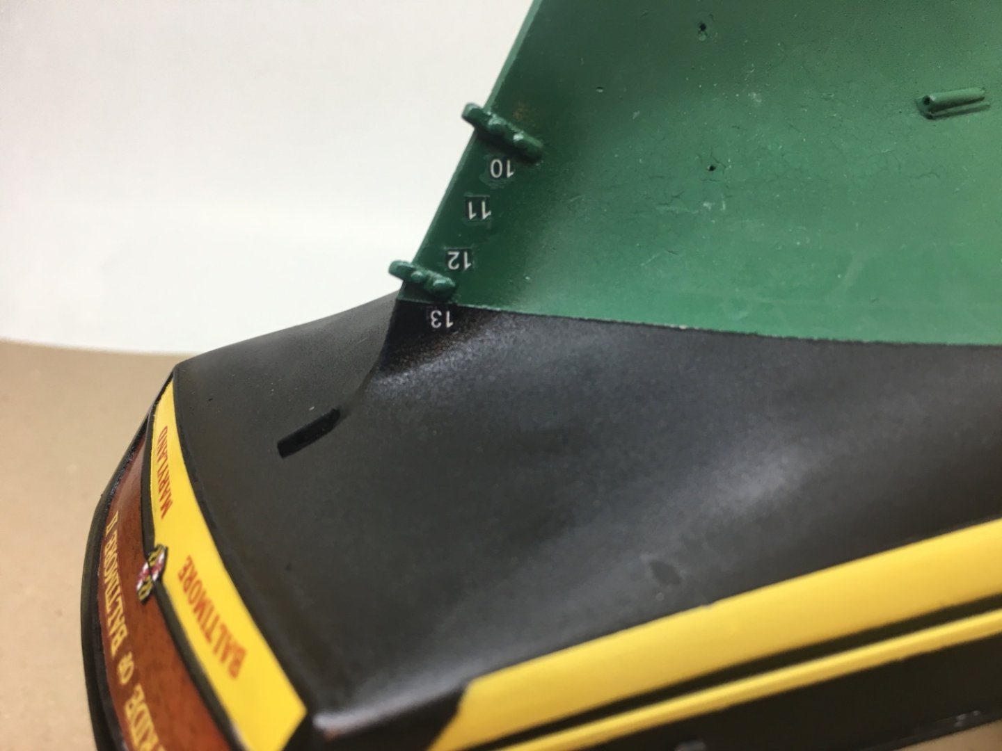
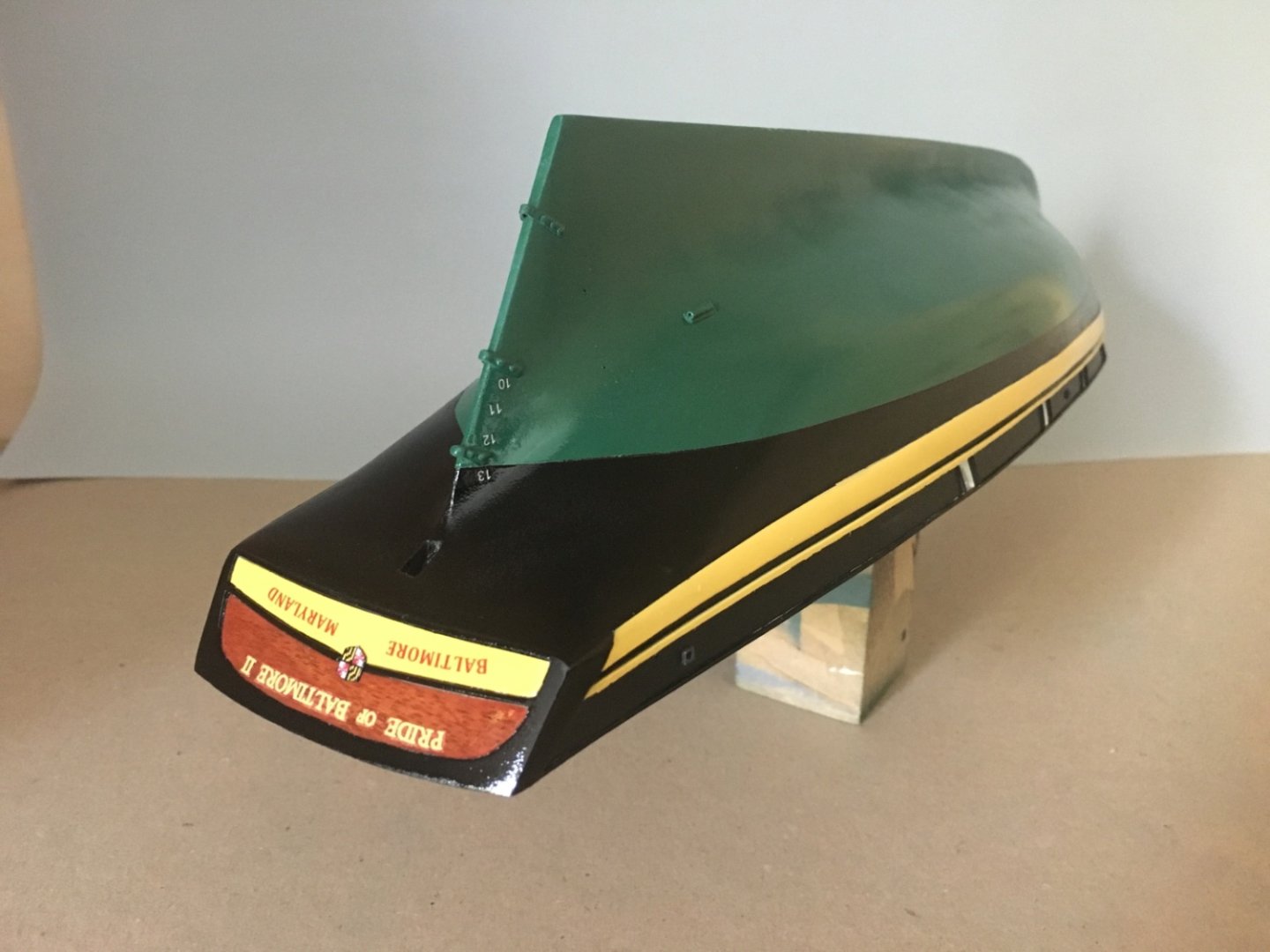
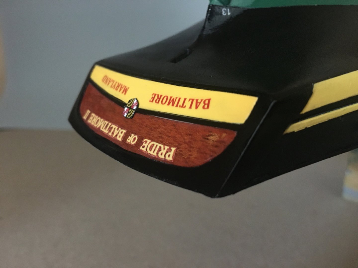
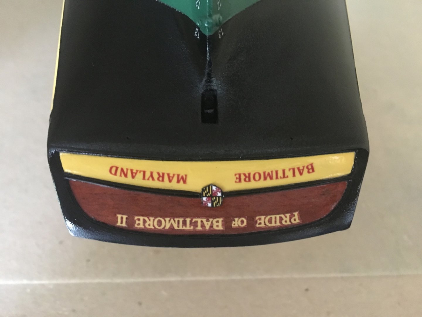
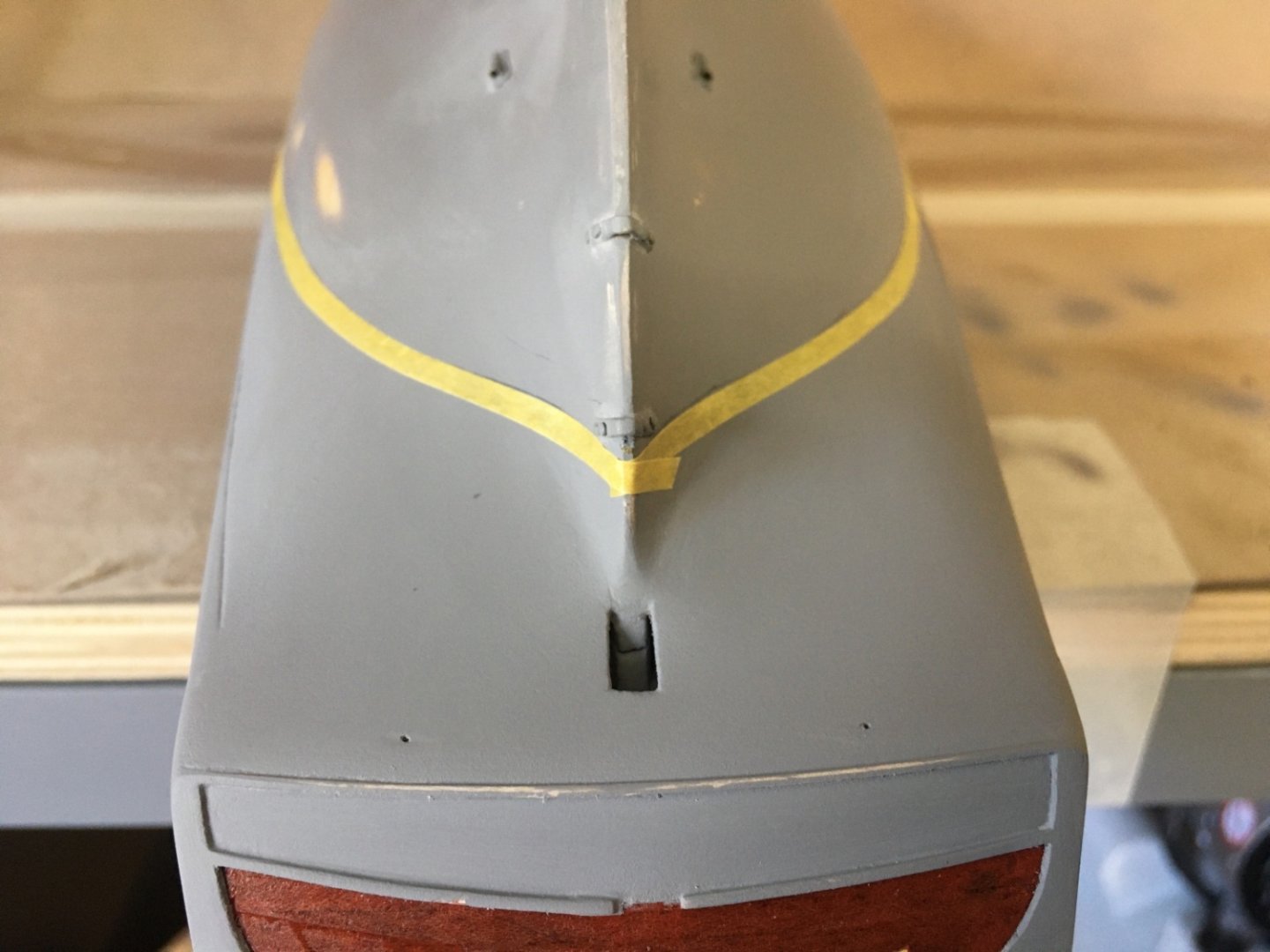
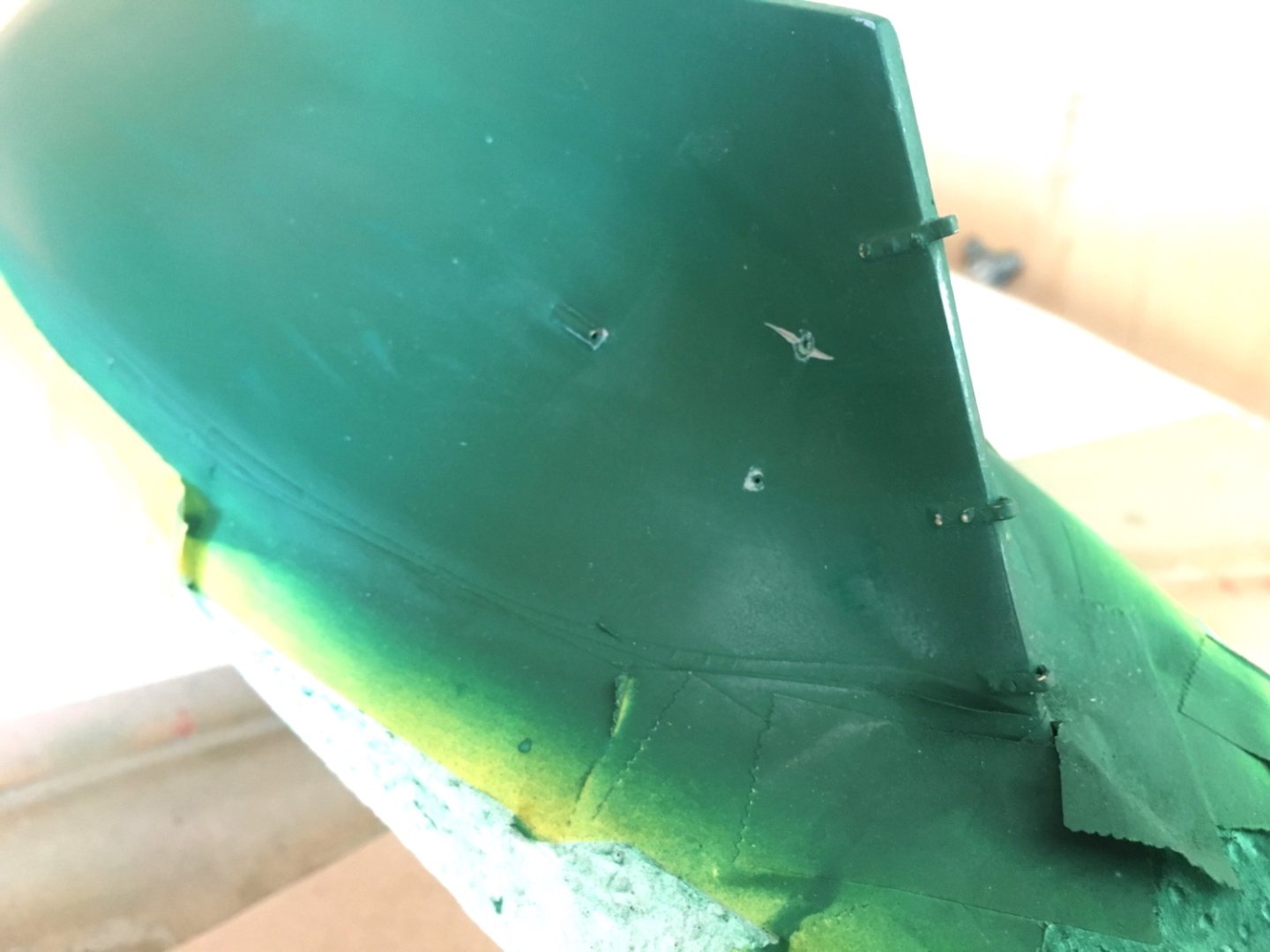
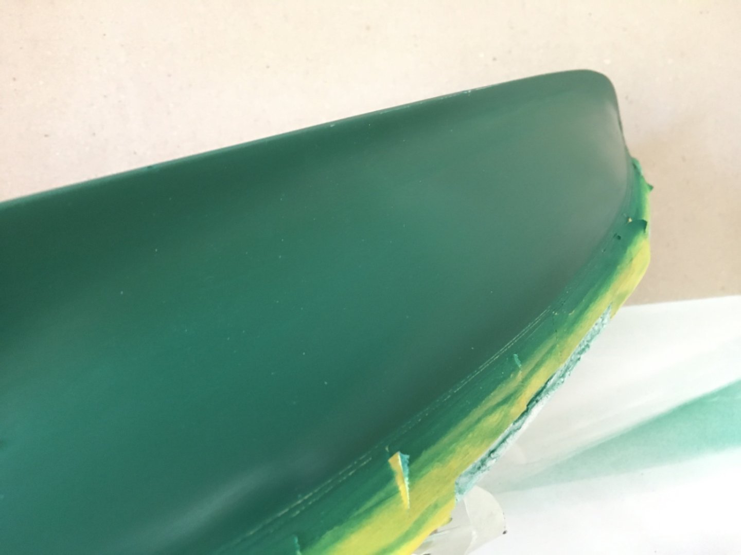
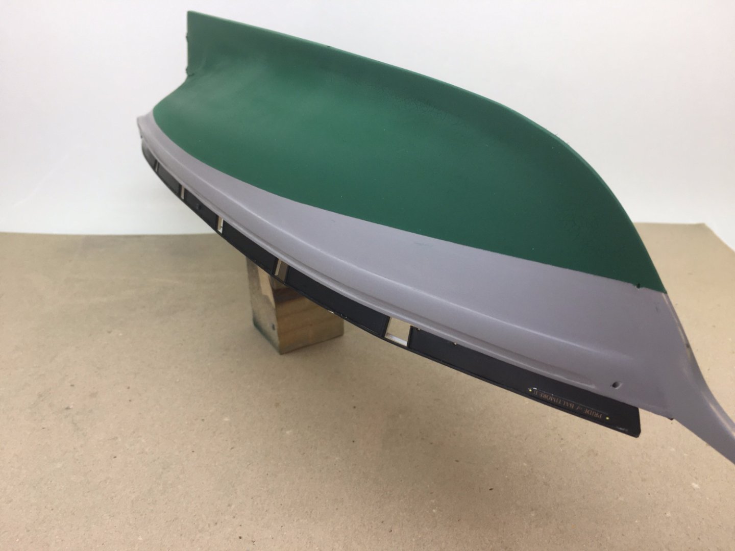
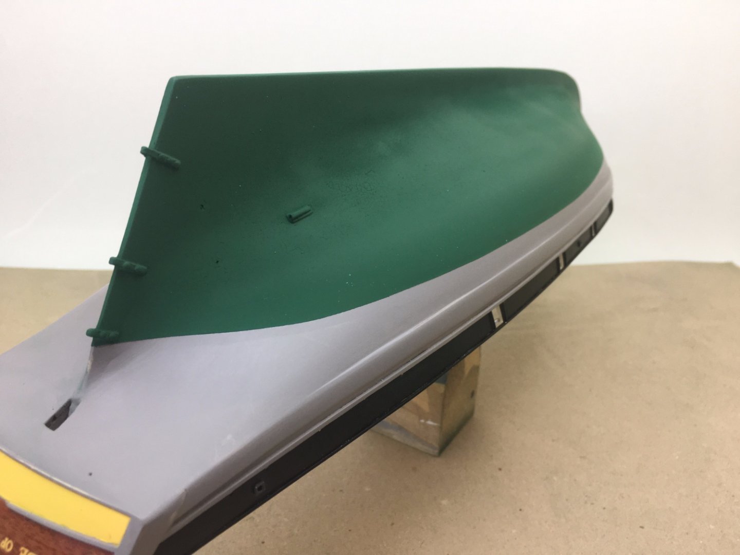
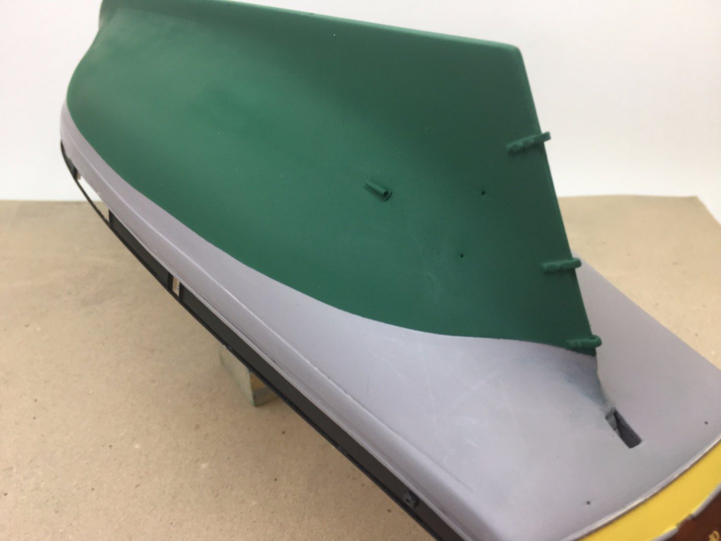
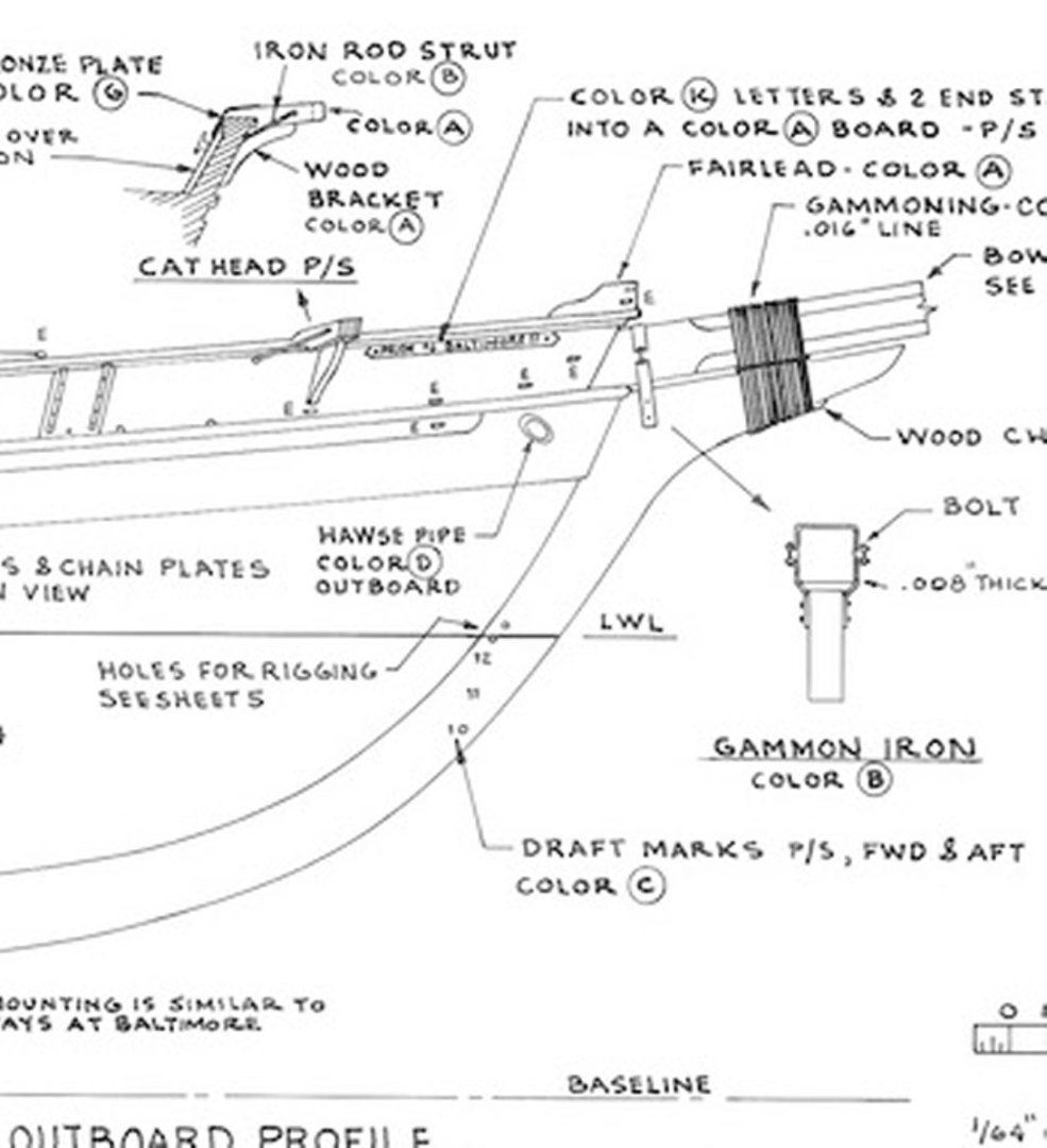
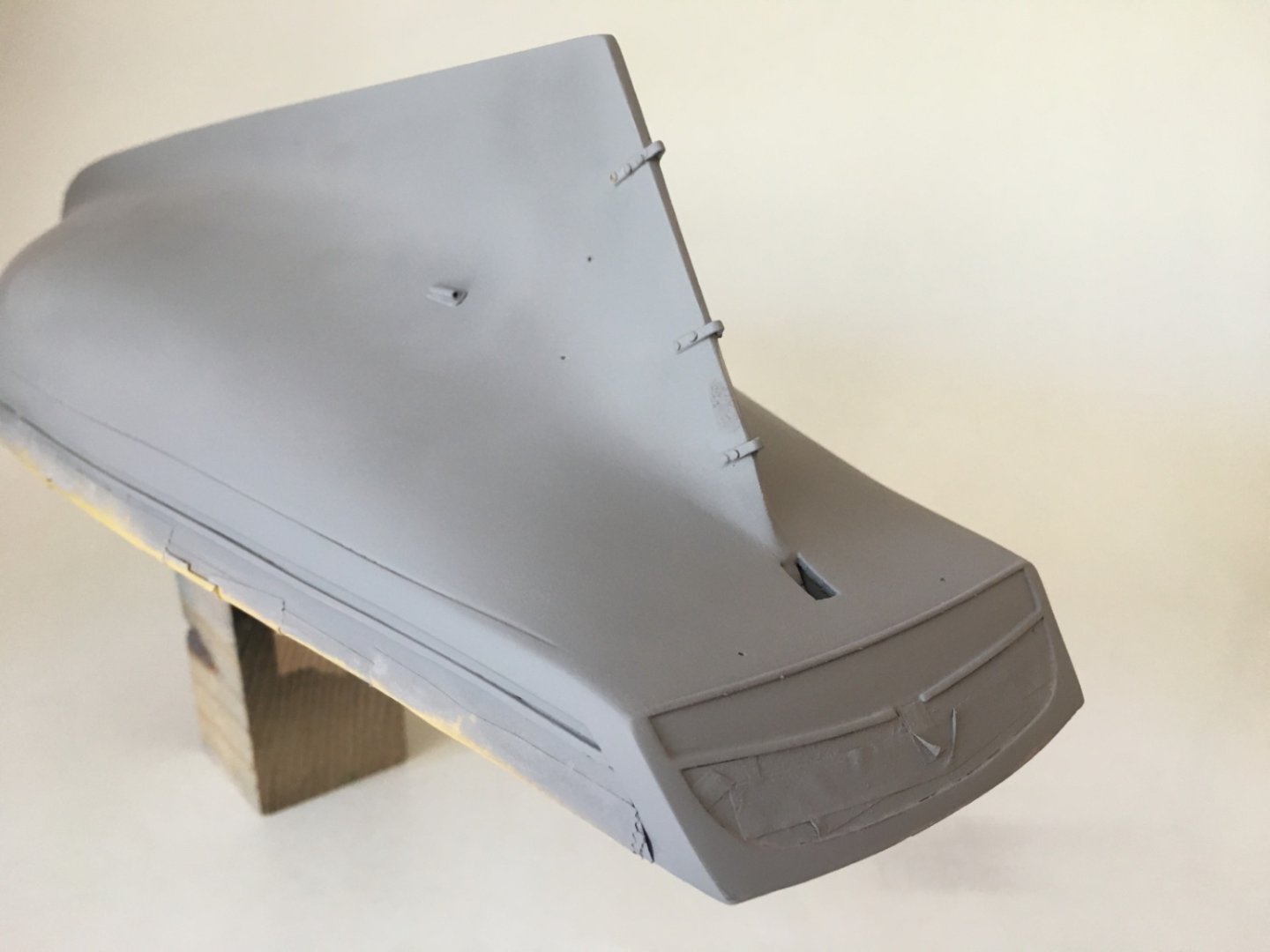
After painting the green of below LWL, I planned to paint first the black areas of the hull and the rudder. The reason of this choice was simple : as the yellow areas to be painted ( the wales and the outboard edge of plank sheers) are higher in level when compared to the neighboring black areas, it would be easier to mask the black painted areas once they are painted. The holes at the stem for bowsprit bobstays were opened at this stage. I think it would have surely been better to drill them before the green paint step. After careful masking, which took almost a day, black paint was airbrushed keeping all the factors causing the disaster in green painting. Masks were removed after 2.5 hours and this time things went as planned. Photos after black painting and mask removal. Rudder After 48 hours and masking again, the yellow paint was airbrushed. Yellow paint was also acyrlic commercial auto paint. Here are the photos after yellow paint which completes the hull painting. After the hull painting was finished , the next step was installing lower transom lettering, Maryland amblem on the transom and depth gauge numbers on the sternpost and stem. ' Baltimore Maryland' lettering was as a decal. After 2 coats of gloss coat to the yellow area of the lower transom, that lettering was placed. Maryland amblem was also ready both as a decal and a print on 300 grams photo paper. I forgot to mention that I found the photo of the amblem on internet. The amblem cut from the photo paper was used and it was placed after the edges were painted black with a marker pen. The depth gauge numbers were also decals. They were prepared as white numbers on either black or dark green backgrounds. Here a photo of the decals on white decal paper. On the paper you can also see the decals of the ships boat 'chasseur' and the figure on the bowsprit cap. Here are the photos after all the lettering above is placed. Now it was time to apply the gloss coats of the hull. There were 3 reasons and need for this step 1. To cover the decals in order to level them with the surface. 2. To improve the borders between color trabssitions 3. To protect the paint until the final satin coats. I used Tamiya X-22 gloss coat thinning it with Tamiya acrylic thinner with a 1:1 ratio. Iwata gravity feed double action airbrush was used under a 0.5-0.8 Bar pressure. 2 coats were applied. Additional one coat was airbrushed on the decal placed areas. The model was kept in a closed environment for 72 hours . Here are the photos of gloss coat step.


- 114 replies
-
- 3
-
-
- Pride of Baltimore II
- Model Shipways
- (and 1 more)
-
Hello Fuji Good luck with your project. I finished POB II a month ago and posting a retrospective blog nowadays. It took me 27 months but believe me , I enjoyed every step of it. Please feel free to check the posts which might give you some ideas on 'how I did it' and 'what must not be done' . Best regards Halit
-
Indeed it was . I don’t think it was the mismatch of the primer and paint because there was no problem in the black and yellow painted areas as you will see in the post I am will be uploading later today,
-
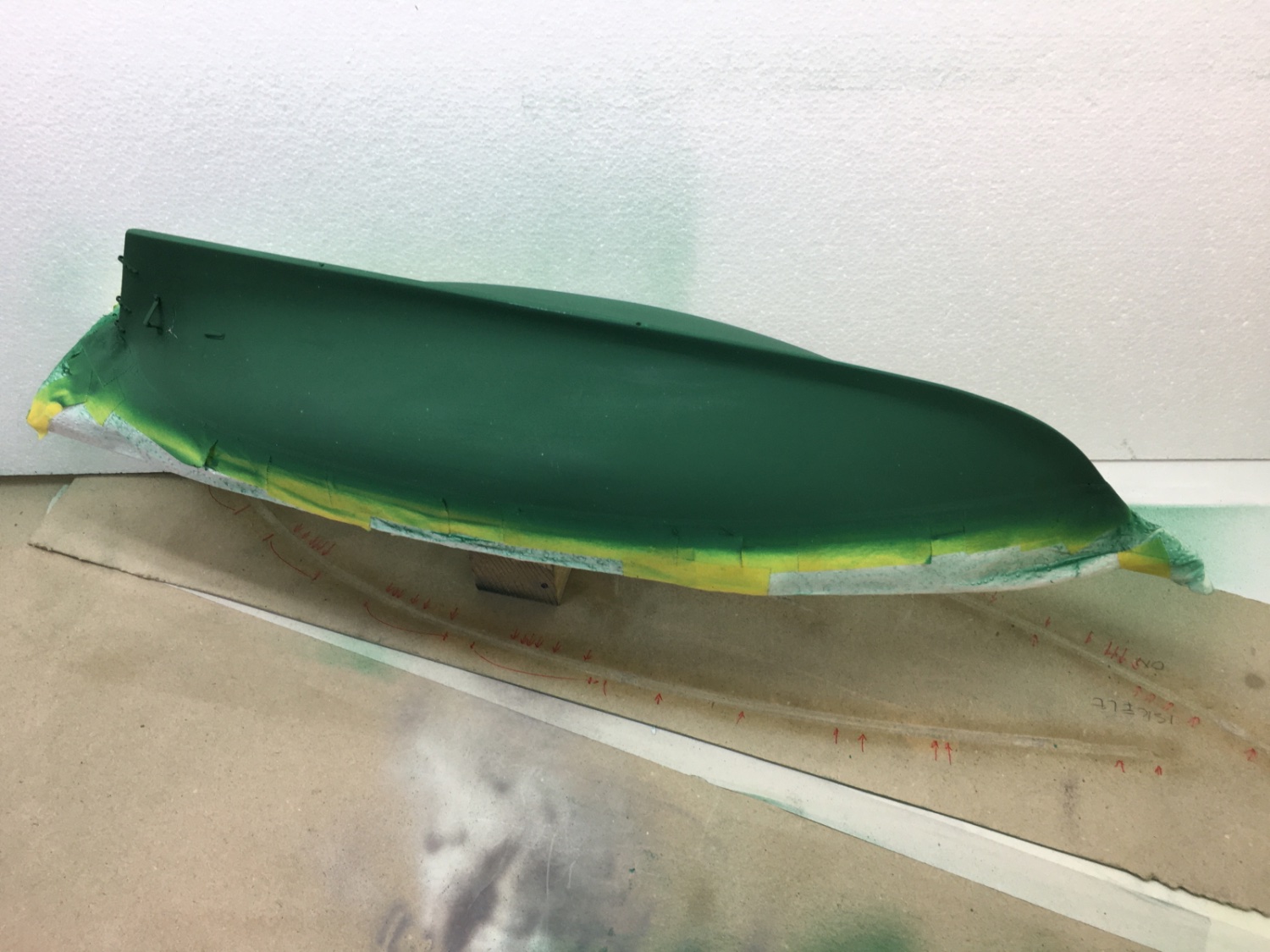
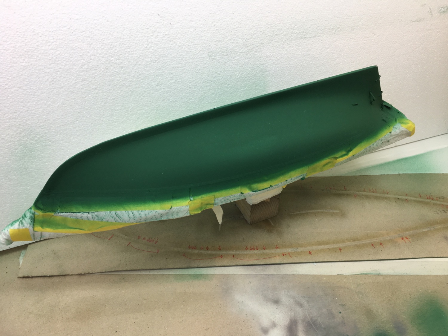
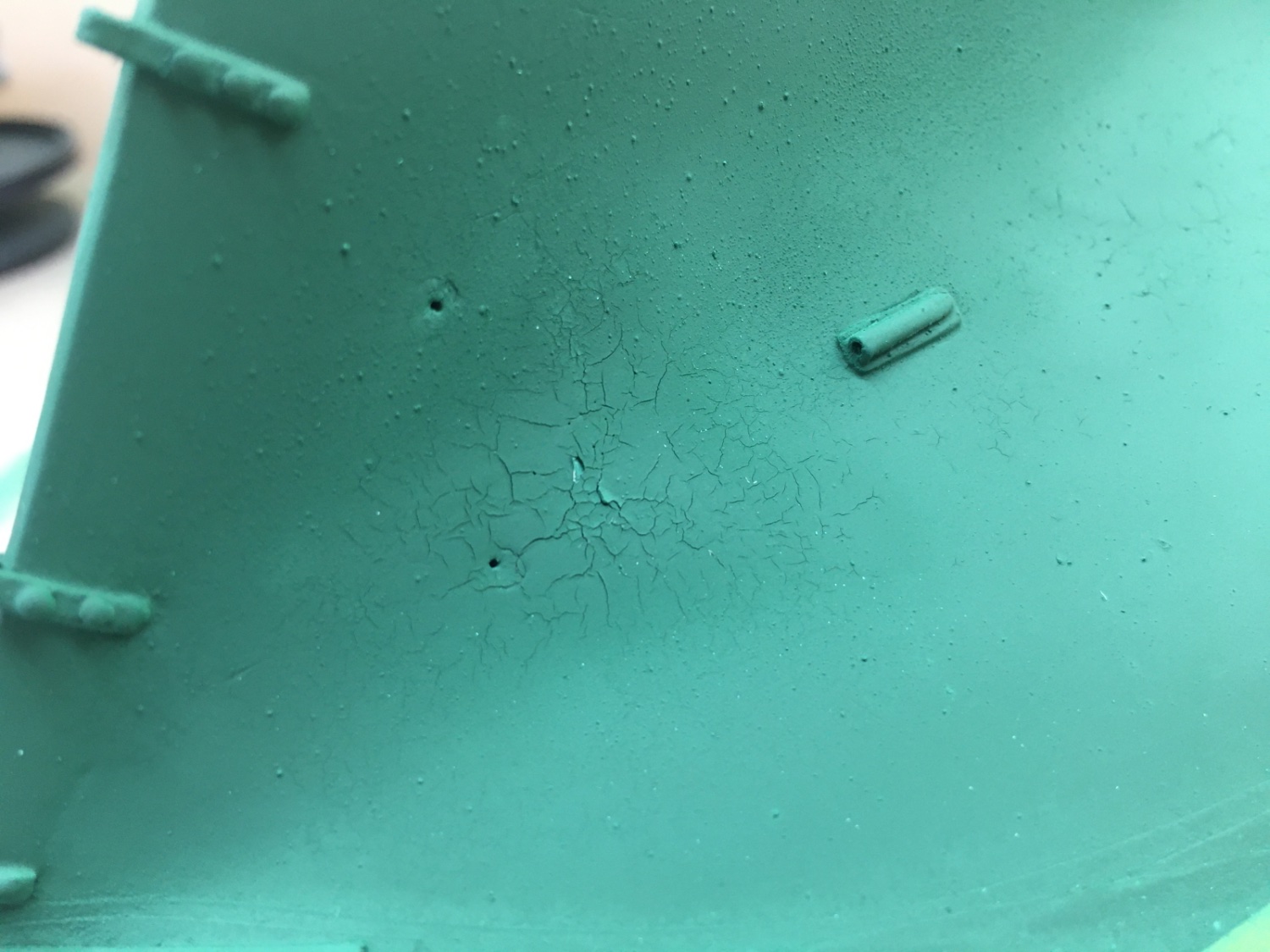
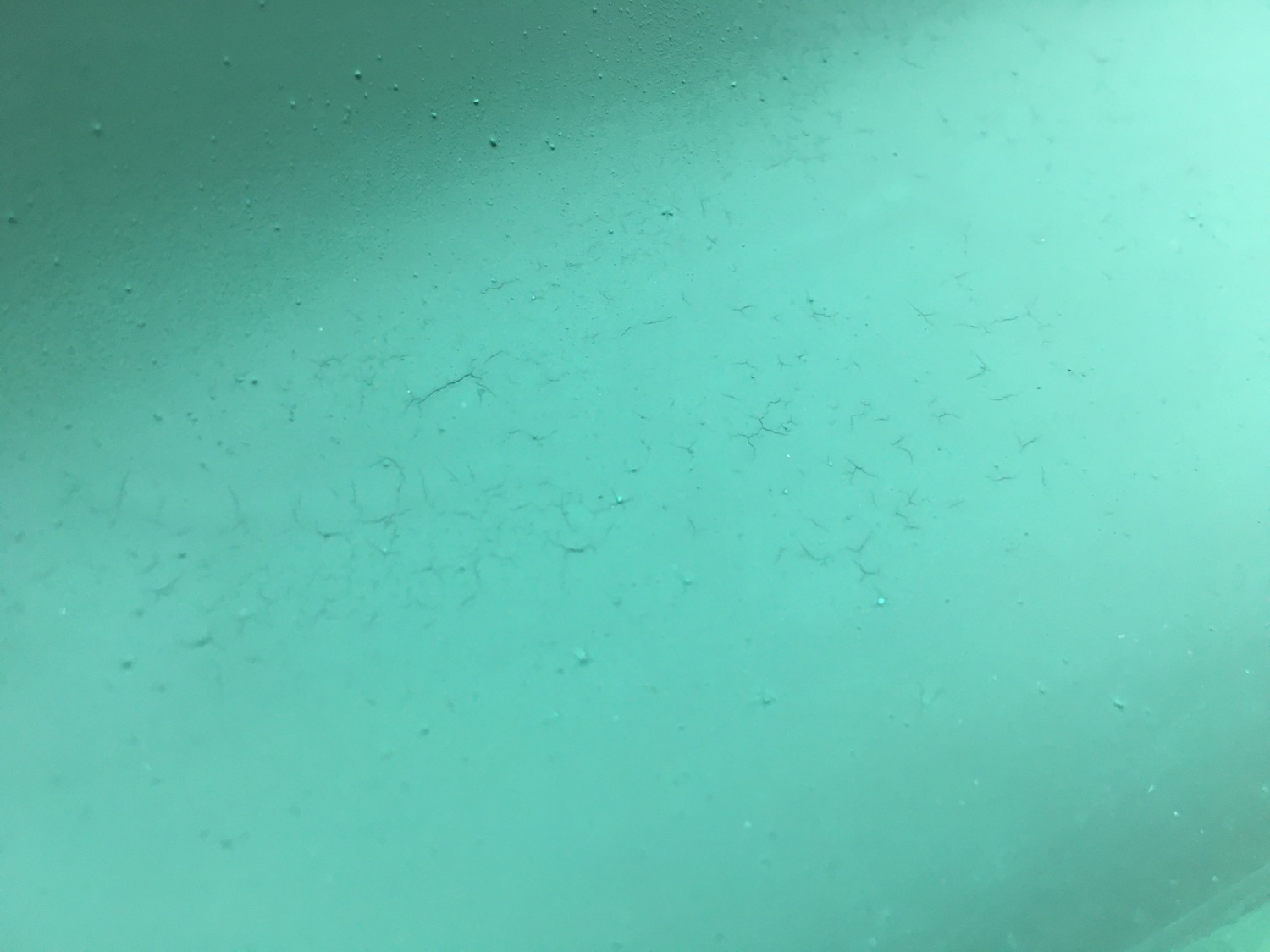
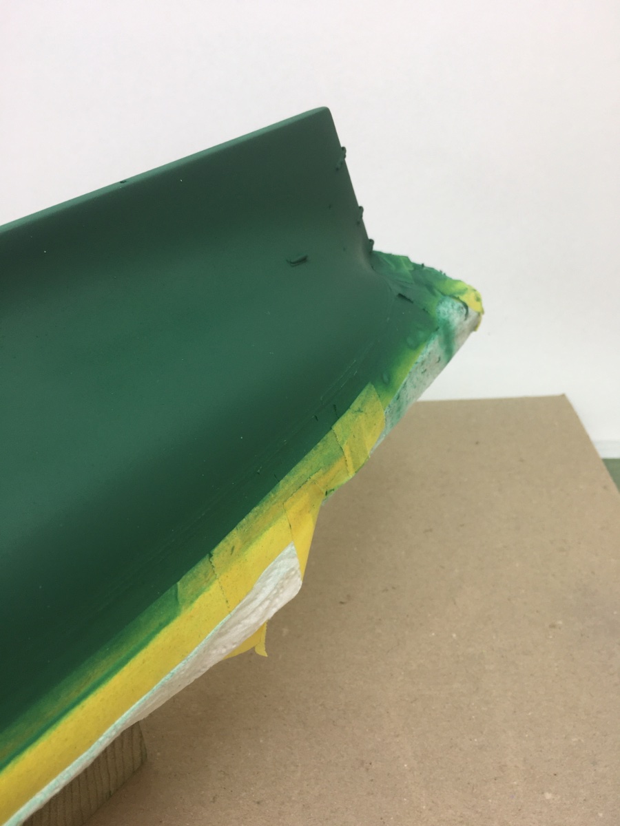
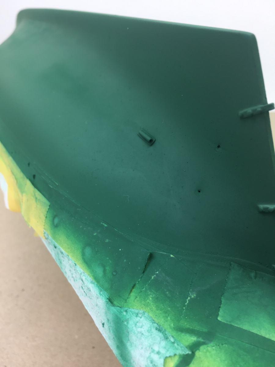
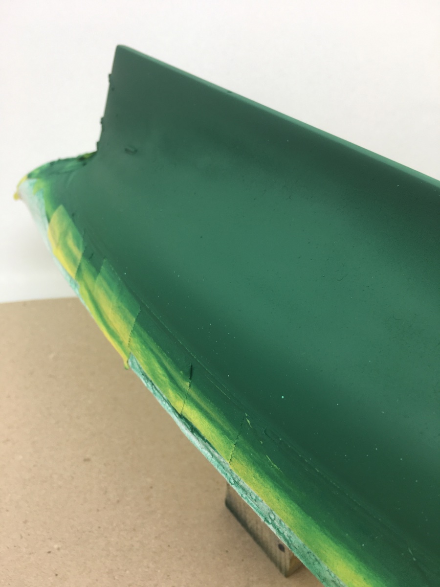
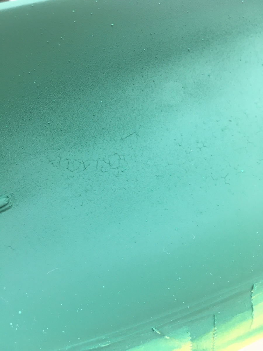
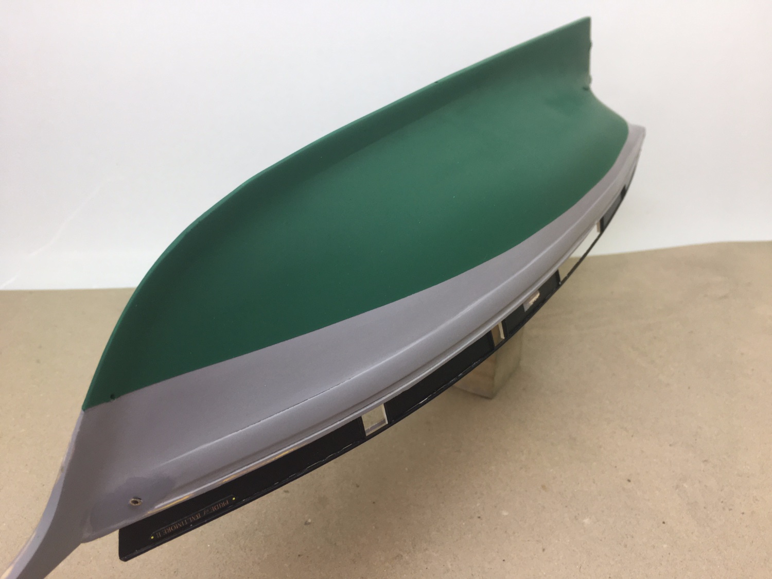
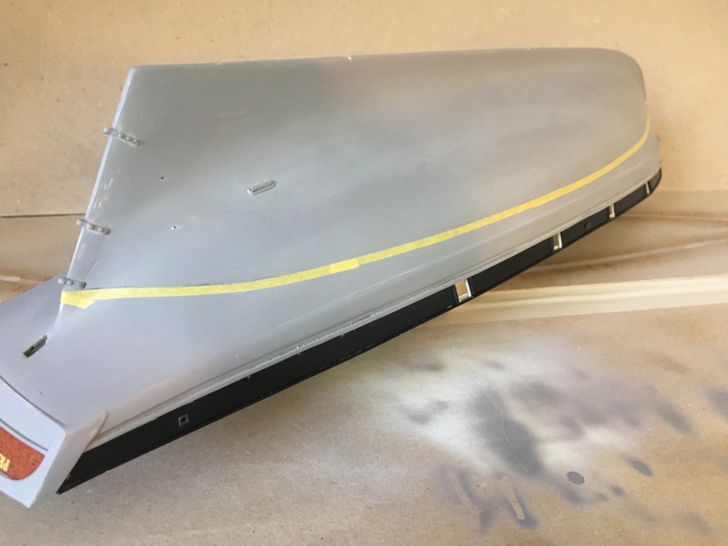
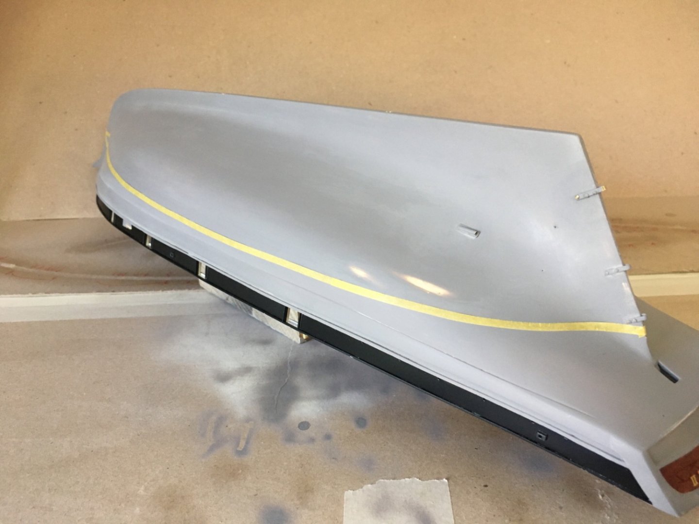
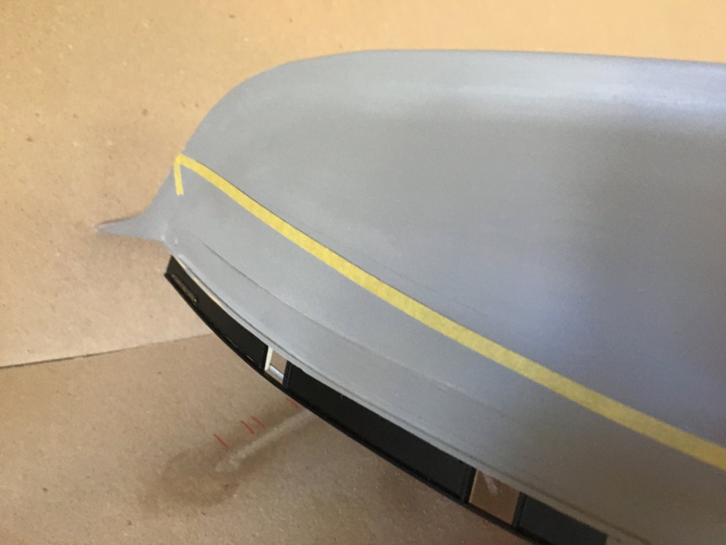
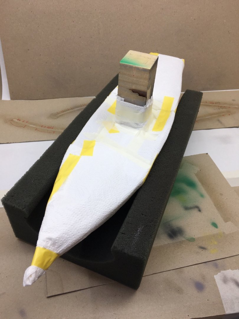
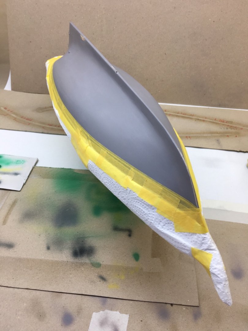
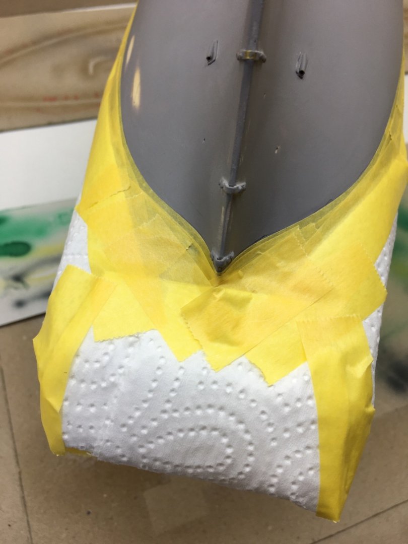
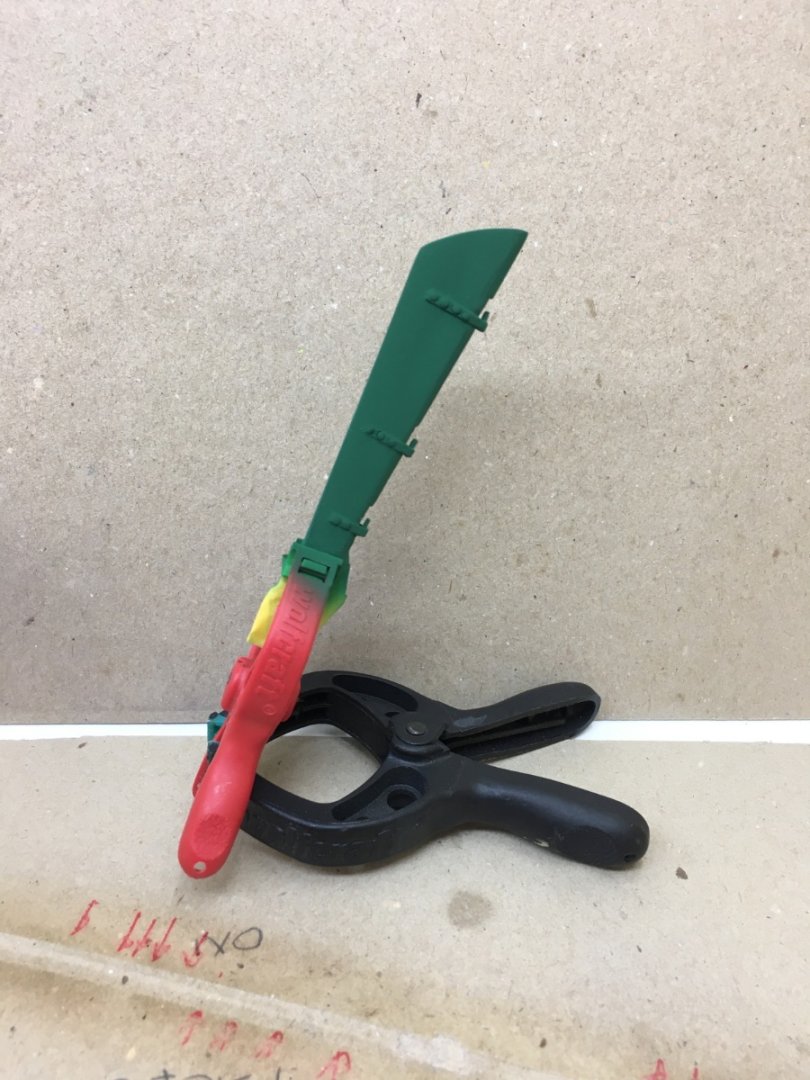
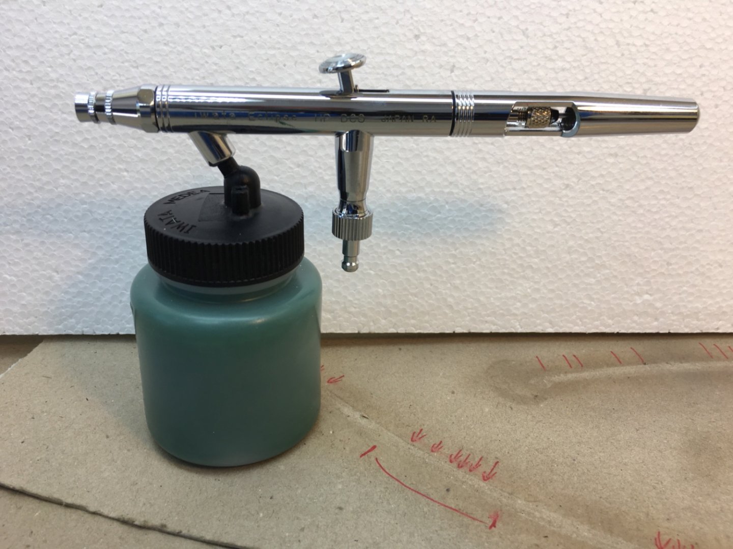
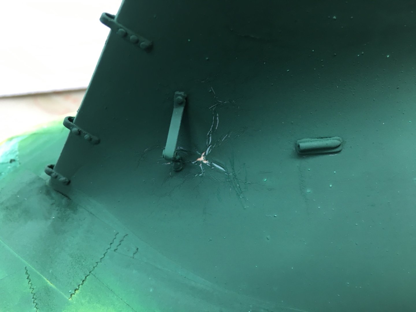
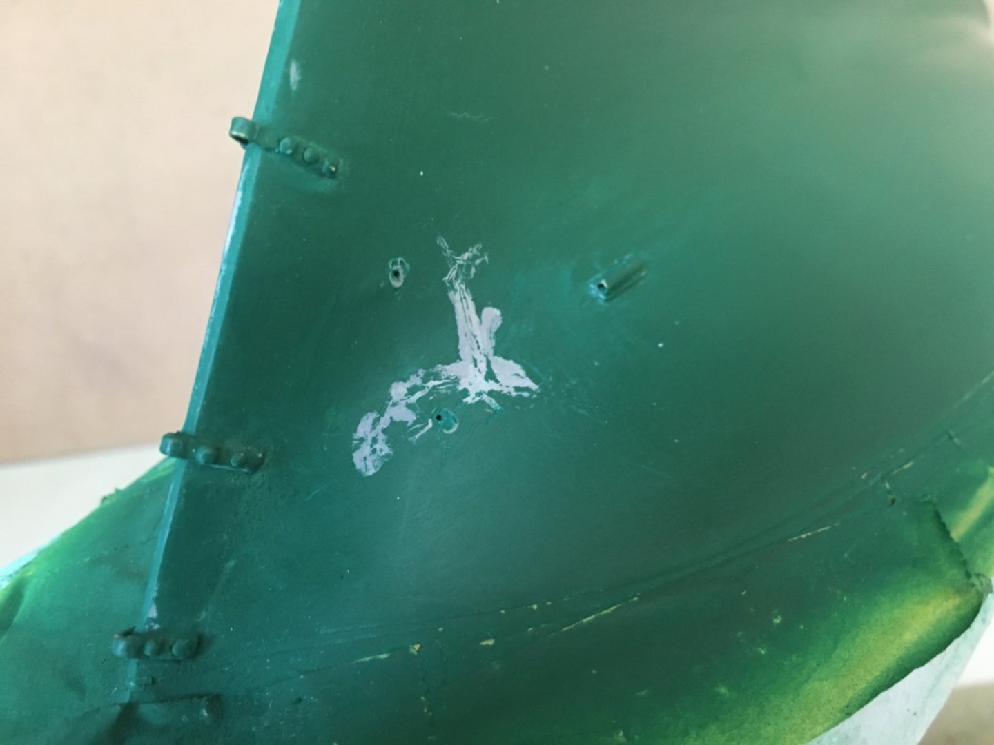
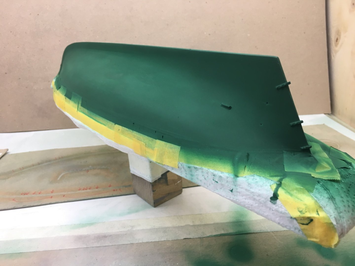
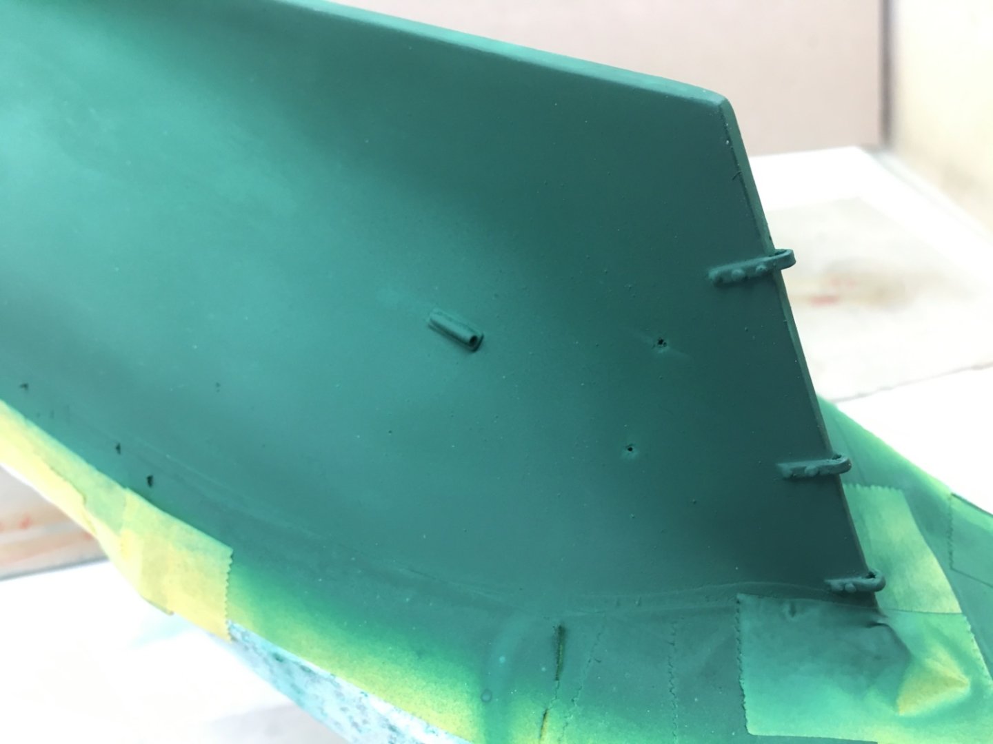
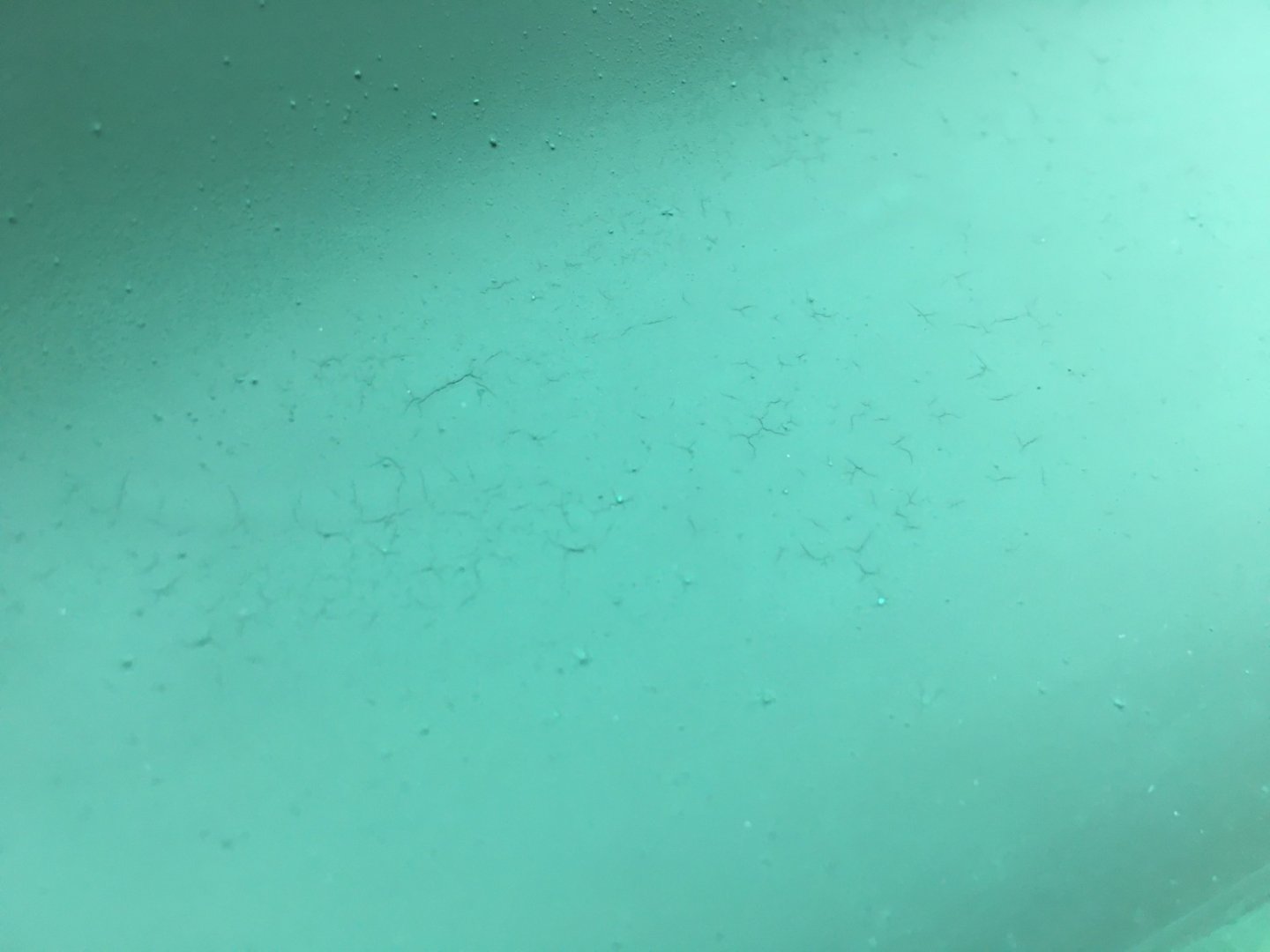
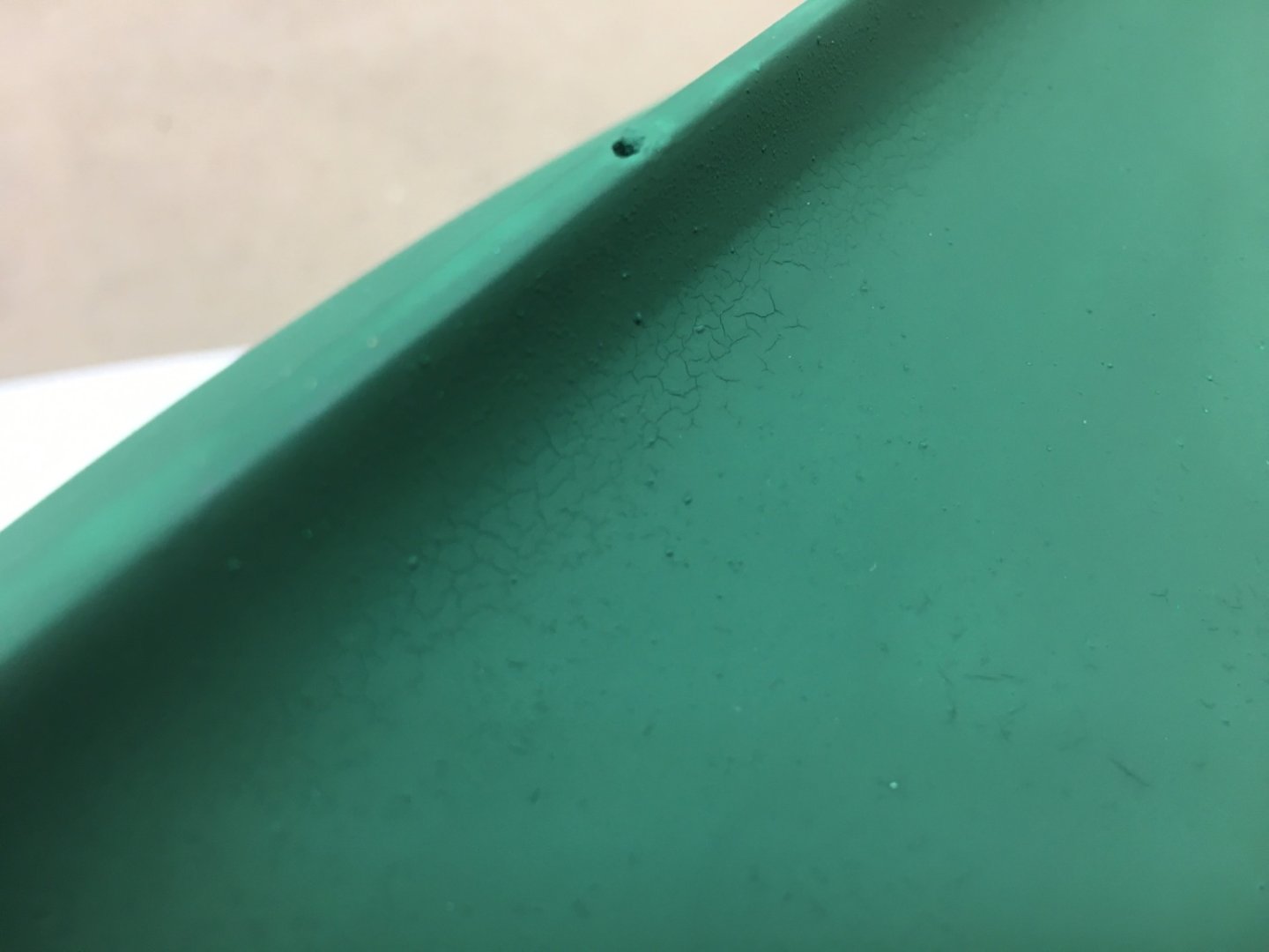
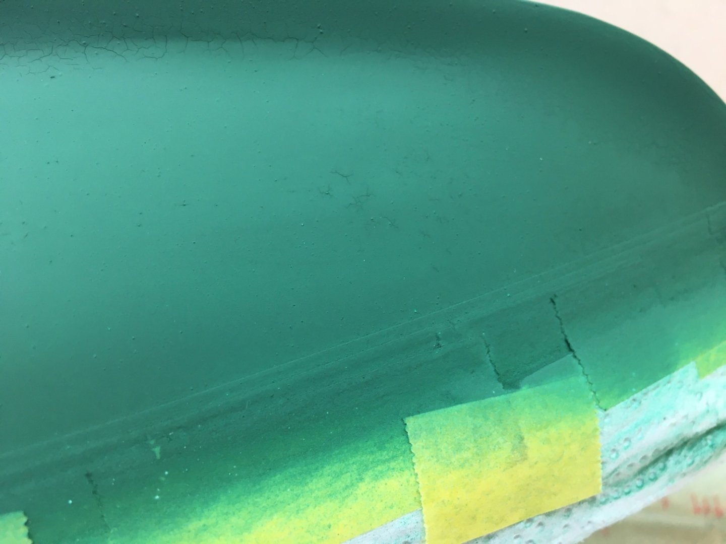
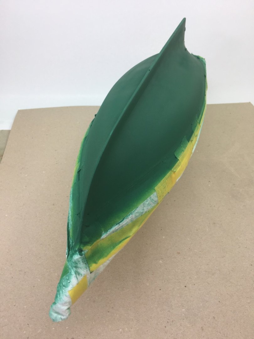
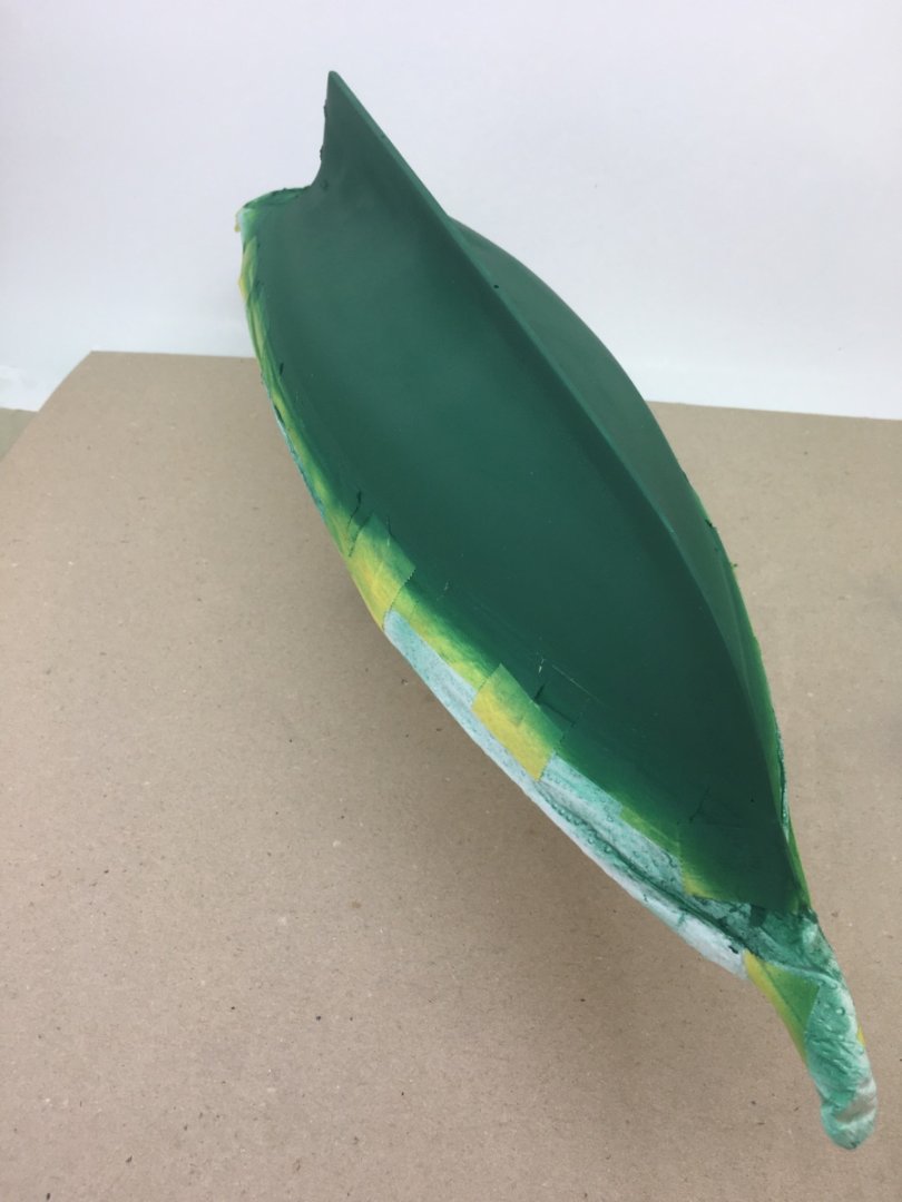
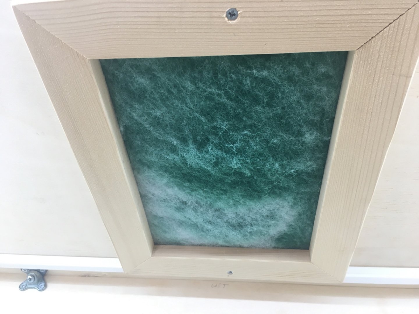
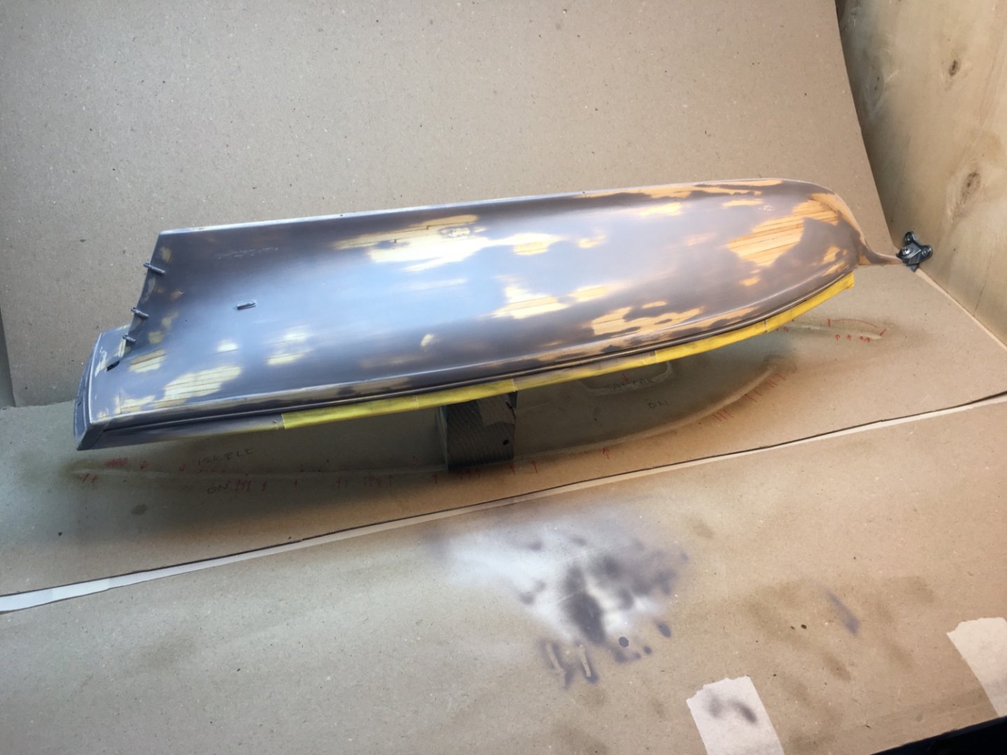
After the cure of the grey primer I decided to start the hull painting with the green below the LWL. A 3 mm wide Tamiya masking, with one edge freshly cut with a new #11 blade using steel ruler on glass surface, was placed right at the upper side of the drawn LWL. The rest of the hull and the deck was masked in the same manner like before the primer coat application. Commercial auto paint was used for matt green color and the code of it was RAL Design 160 30 25. Paint was diluted by commercial acrylic thinner with 1 : 1 ratio. The rudder was painted first. Then the under surface (The side facing the hull) of the propeller shaft struts were painted and they were installed on the hull. Iwata bottom feed double-action airbrush with 0.5 needle was used. 7-8 drops of retarder was added to the paint bottle you see below. Pressure around 1 Bar was used throughout the procedure. The reason for the choice of the type of the airbrush was to provide an easy flow of paint while controlling the flow amount. After the two coats of paint disaster struck. I felt like hitting the wall. There were dry paint particles and droplets almost everywhere. After 30 minutes those particles were cleared off by pressurized air as they were not attached to the paint. I tried to clean the remaining ones by a dry brush. Then I did something which was unnecessary and completely wrong. I tried to sand the surface with #2000 paper wetted by water in which a few drops of dishwashing detergent added. Initially the result seemed OK. After the surface was dry I airbrushed two more coats by using Paasche single action bottom feed airbrush. Unfortunately I was demoralized and did not even took photos after the first two coats. Here are the photos taken at the end of the disaster day. Particles , fisheyes and spider webs can be seen clearly. Although in the photos of the whole hull taken from a distance the result seems to be acceptable, in the ones taken close problems can clearly be seen. The next day , after consulting modeler friends in our local forum, I started the repair process. The propeller shaft struts were removed as they clearly impeded the flow of paint and changed the flow direction. The paint on them was completely removed. They were primed and color painted again and put aside to be installed later. The area where struts were removed on port side, was filled with primer using a brush. After 48 hours I started the sanding the primer filled area and the rest of the hull. Sanding was done in the order of #600, #800 and #1500. The next day after the sanding another coat of paint was applied. This time I used Iwata gravity feed double action airbrush with 0.5 mm needle. 0.5 Bar pressure was used and the the tip of the airbrush was kept around 5 cm from the surface. Although there were minimal paint deposited points, the result on the starboard side was acceptable. However on the port side there were cracks in the paint as well as particle deposits. The cracks started to be seen once the paint started to dry. As the starboard side was better, I thought the insisting problem on port side is not to application technique but underlaying surface problem. However the sanded paint before the process was OK ? Problems persisting on the port side After 48 hours sanding was done again, using #600 and # 1500 papers. After waiting another 48 hours the final green paint coat was airbrushed. The starboard side was OK as seen in the photos below. On the port side , when looking with naked eye from 50 cm, the result is OK. However, although way more in less numbers than the previous coats, when getting closer and looking with a magnifier glass, there were still areas where paint is cracked. At this step I decided to take off the masks and accept the present condition of the port side paint. Hoping the planned gloss coats followed by the final satin coats will improve the still existing problem, I removed the masks , fortunately , without any problem. Had there been any problem at the paint border, I planned to remove all the paint and prime the hull once more ( probably many of you would have done regardless of the mask removal situation and was the correct way to do !) Photos after mask removal. Now looking back to those disaster days and thinking what went wrong or what I did wrong , I come to some conclusions : 1. On day one after the two paint coats were airbrushed, I should have kept cool and waited until the paint was completely dry. 2. I should have used the airbrush type which I was used to. It was first time I used Iwata bottom feed airbrush. Probably I was a bit awkward and used pressure higher than needed thus airbrushing from a bit far distance causing the paint particles to dry before hitting the surface. 3. Wet sanding was a terrible idea at that step. I should have never done it. 3. Trying to remove the particles with pressurized air was another bad idea and probably caused the obvious cracks under the strut on port side. 4. Of course the lack of surface cleanness was an important factor and probably it was enough for the paint adhesion. I am sure you will have many advices different from the above conclusions and I will be more than happy to hear them . There was one silver lining of the paint disaster. When I checked the exhaust air filter of the self-made paint booth , the green color of it proved the system was working ! I will continue the hull painting with black followed by yellow areas. However on the stern lower transom was painted yellow separately beforehand in order to mask the yellow area more easily when painting the half round molds on the stern later than painting the mold's black first and masking them.


- 114 replies
-
- 4
-
-
- Pride of Baltimore II
- Model Shipways
- (and 1 more)
-
Thanks a lot Patrick, I now know what to do…. Regards, Halit
-
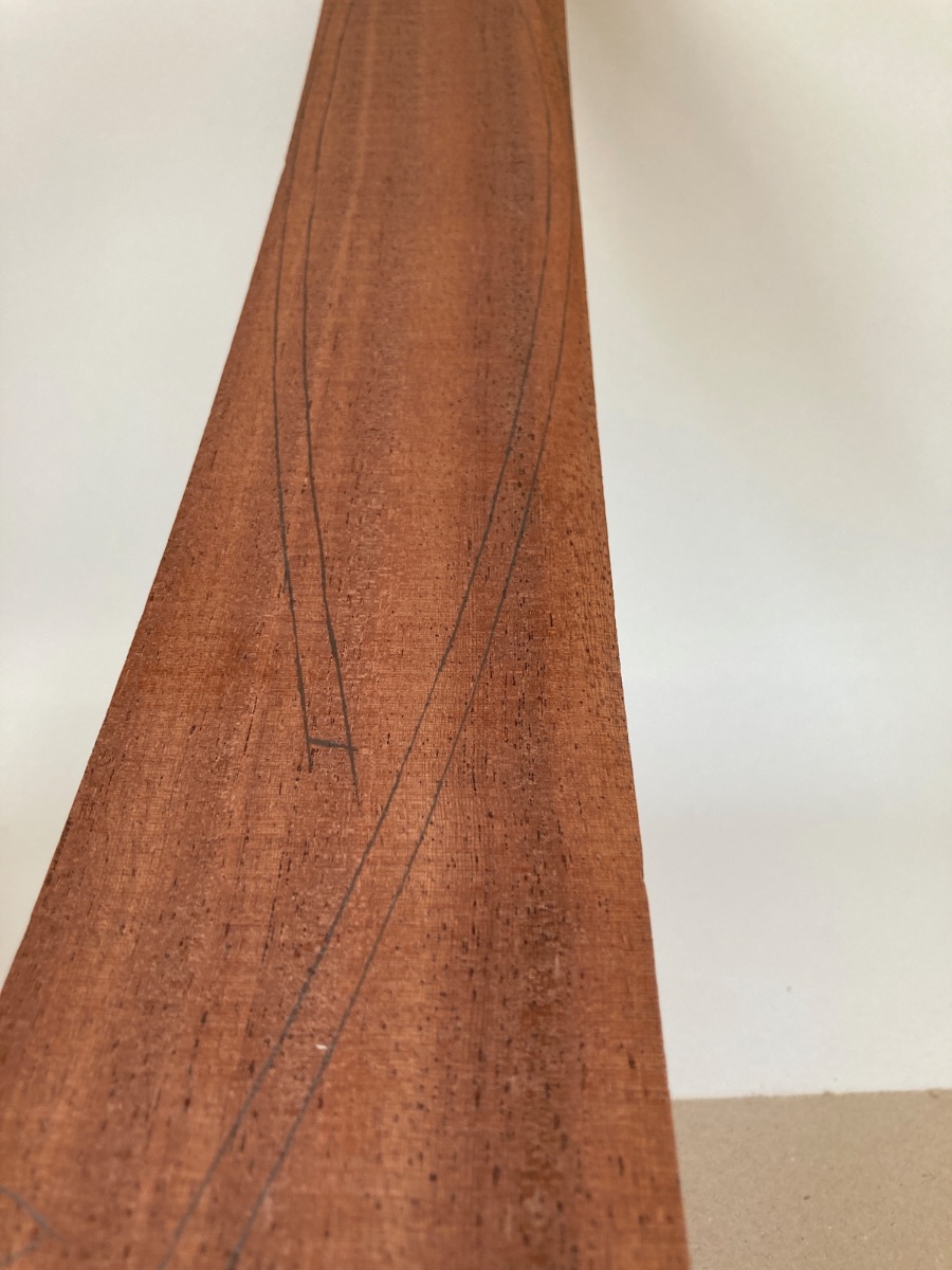
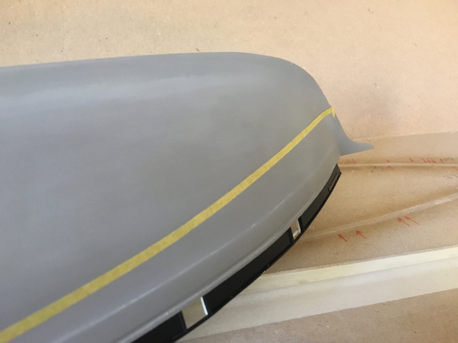
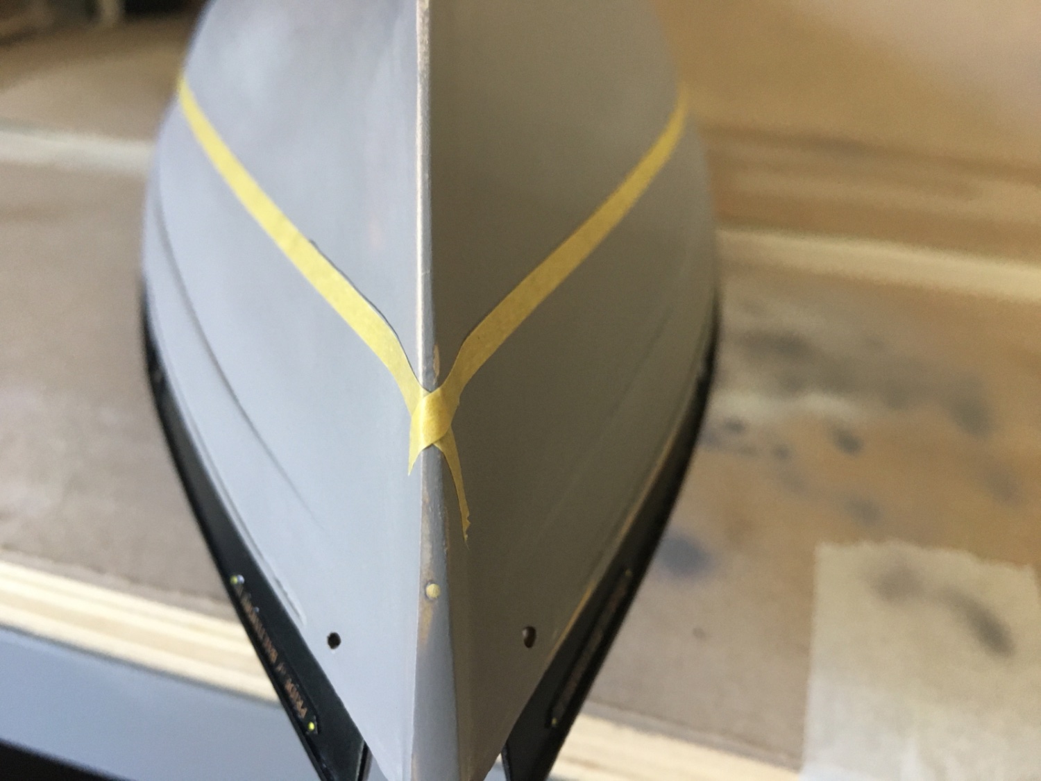
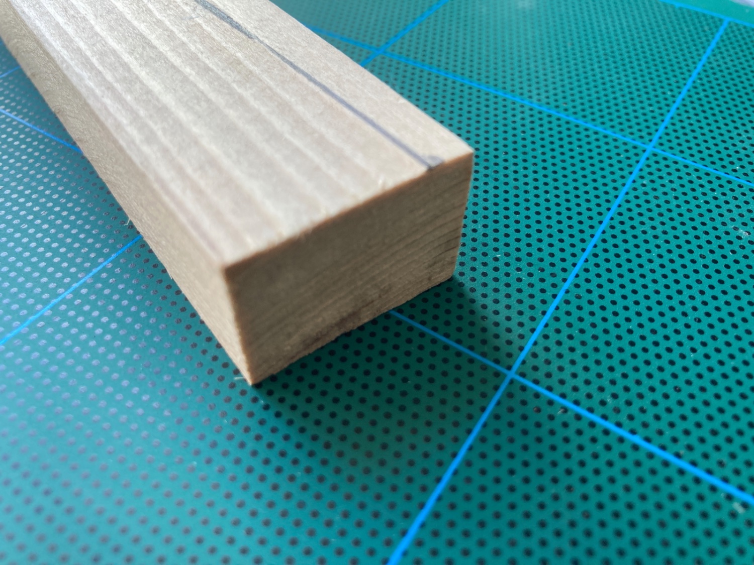
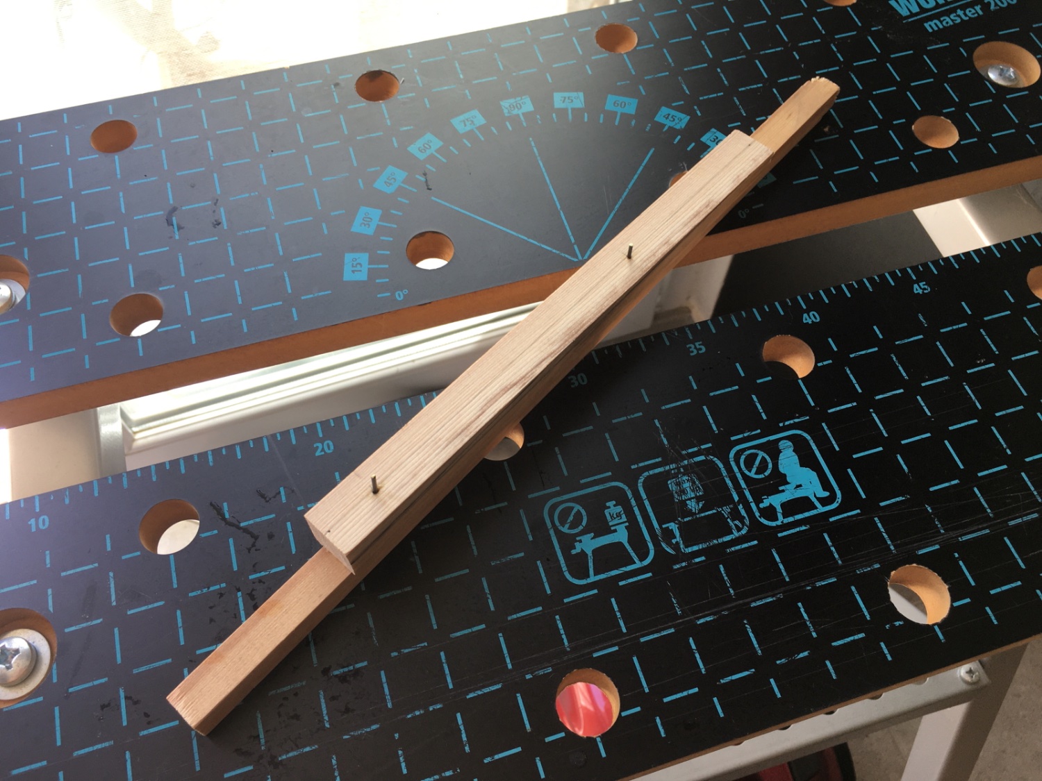
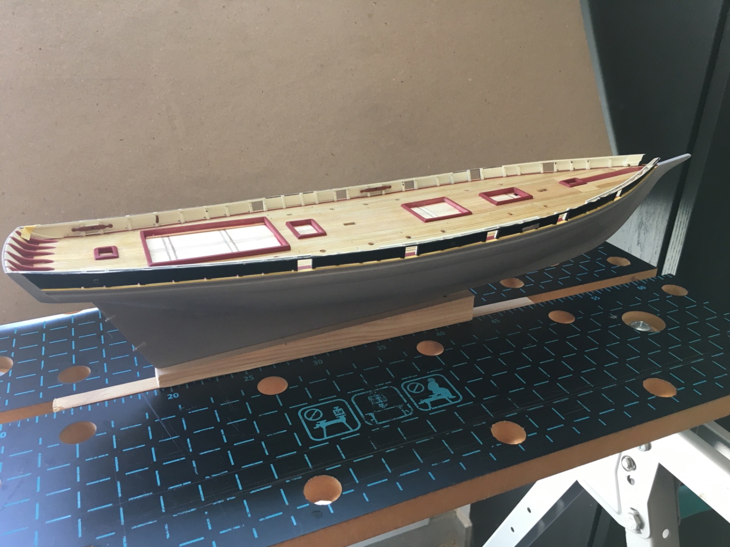
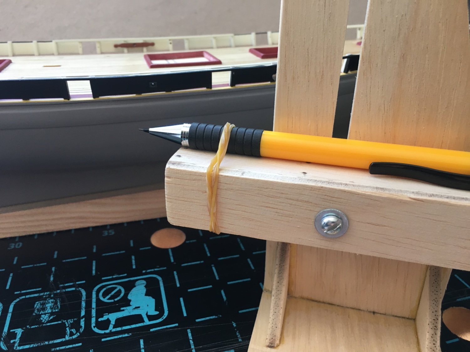
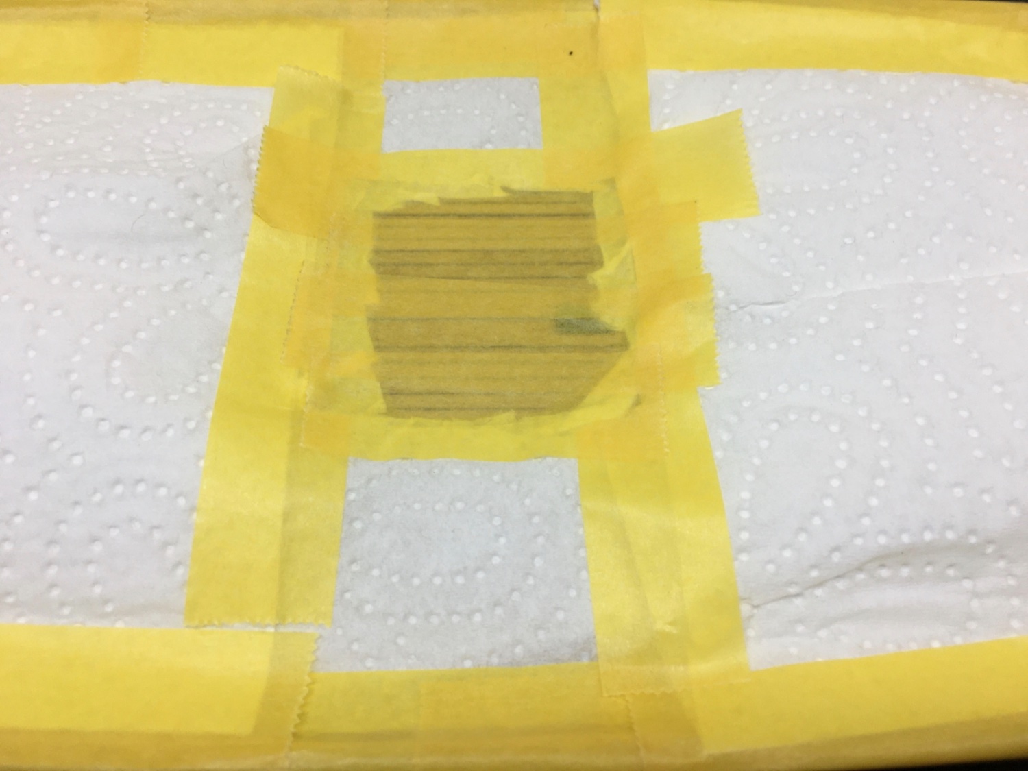
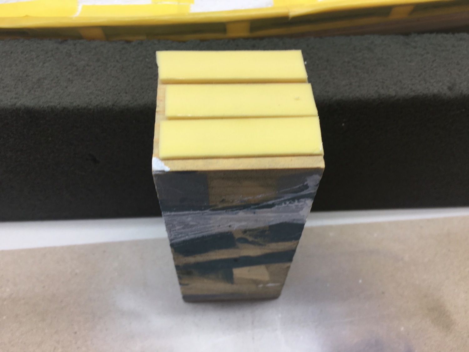
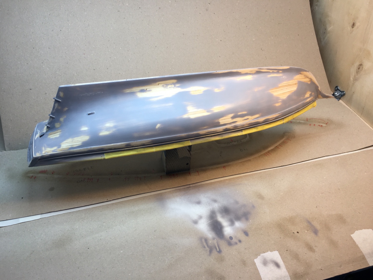
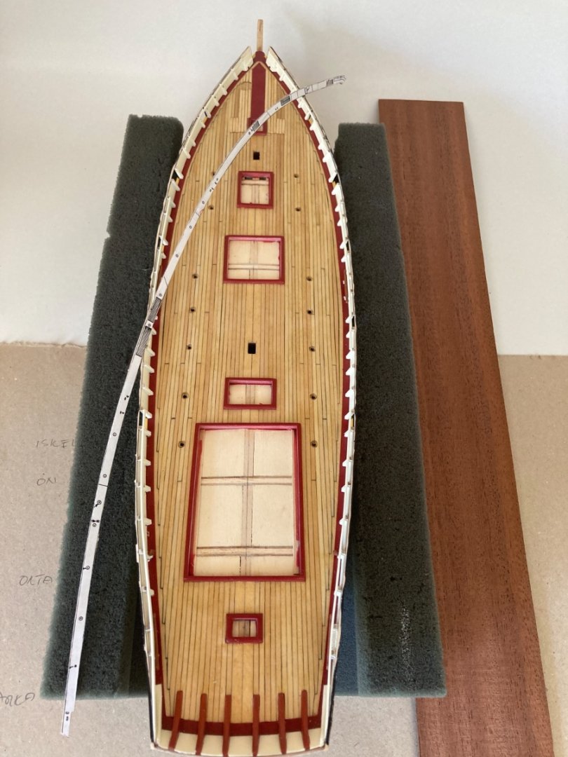
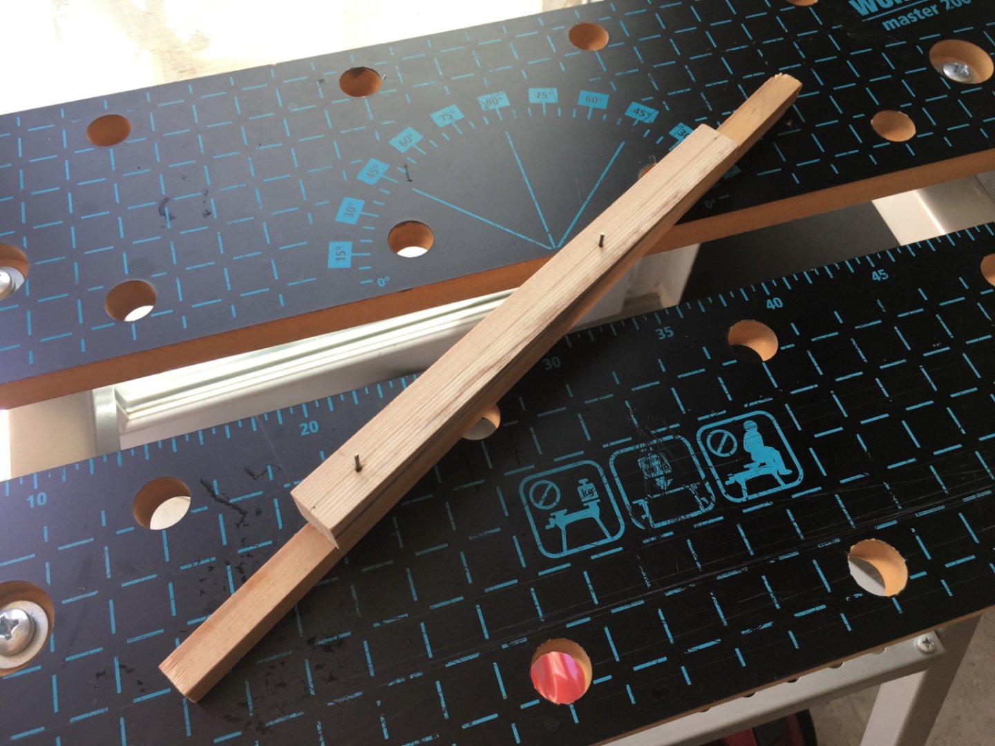
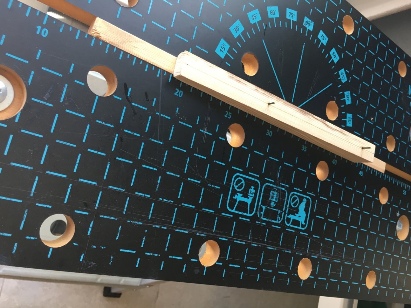
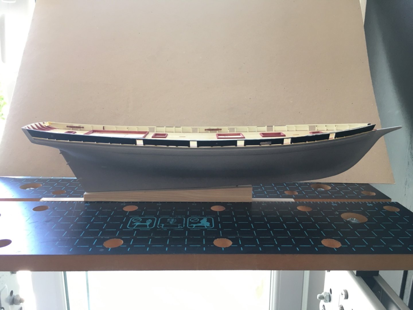
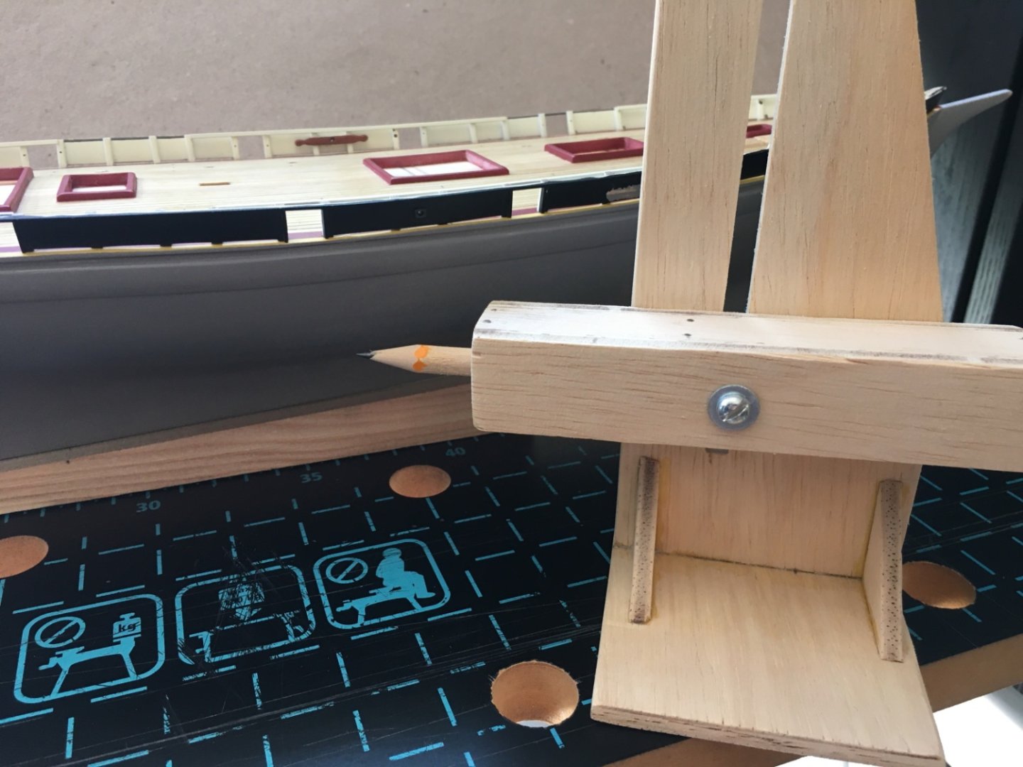
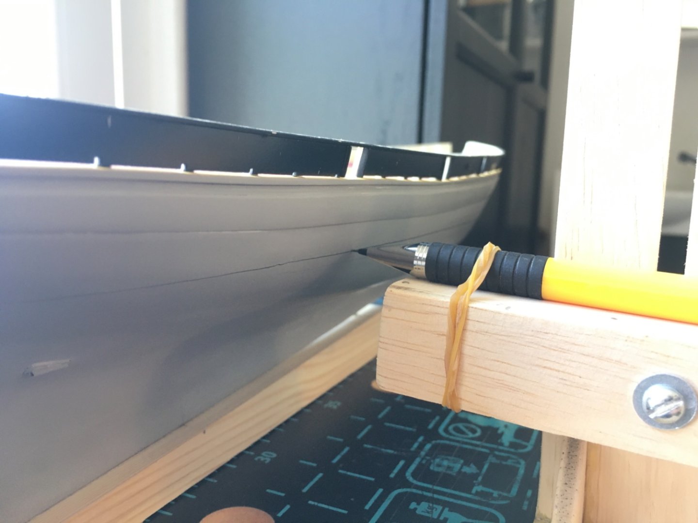
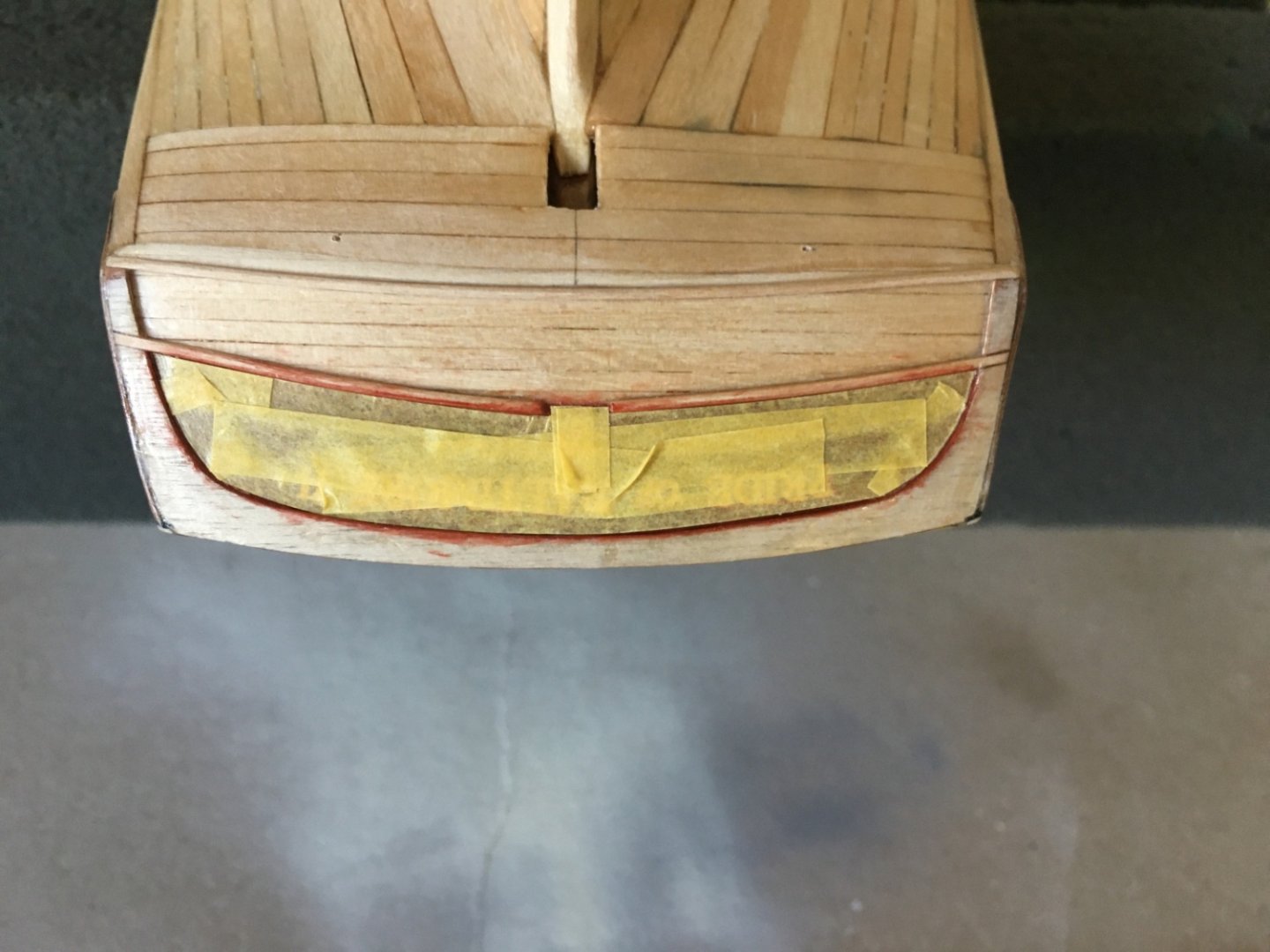
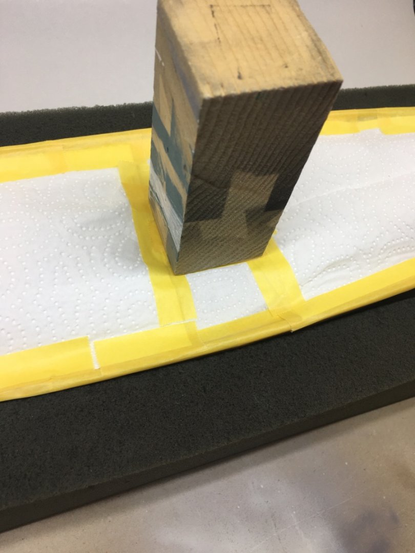
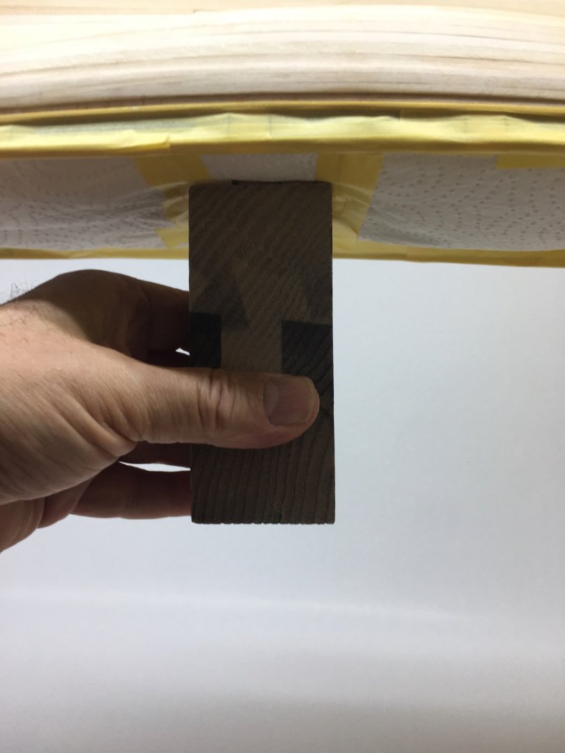
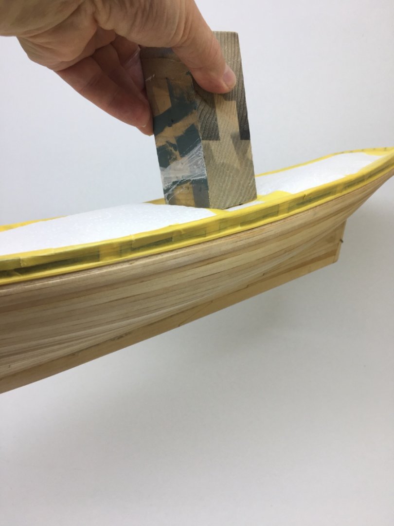
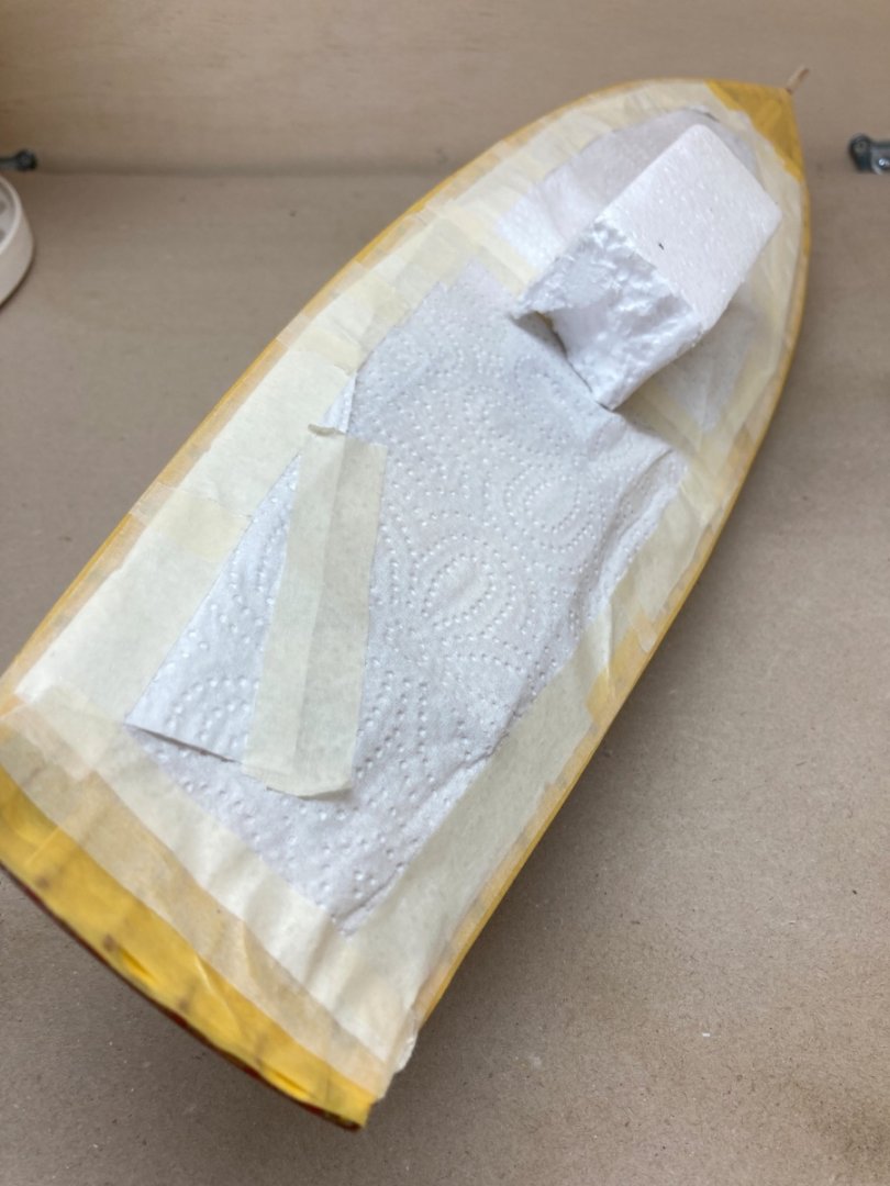
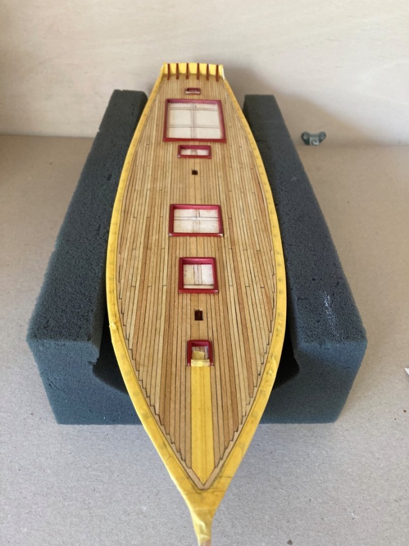
After the primer coat job of the hull, it was time to draw the Load Water Line (LWL). The ship bow is higher than the sternpost-keel corner and makes an angle with the horizontal level as seen in the photo from the plans. The angle measurements were carefully transferred to a square wooden block and a line was drawn. After the wooden was cut with the table saw, another piece of wood with the same length but 1 cm less in wide was cut also. This thinner piece was glued under the first wood piece leaving 0.5 cm space the sides. 1.5 mm diameter holes on the jig and corresponding ones on the model's keel were drilled. Two 1.5 mm brass rods were placed in the holes on the jig. The the jig fixed on the Wolfcraft work table as seen in the photos below. The model was placed on the jig . Modelexpo brand waterline drawer was used. However the drawers original pencil was removed and a 0.35 mm tip pencil was mounted. After careful location measurements taken from, the plans the fore and aft end points of the LWL were marked on the model. Then the LWL was drawn on both side. LWL was also transfered to the rudder at this stage.


- 114 replies
-
- 3
-
-
- Pride of Baltimore II
- Model Shipways
- (and 1 more)
-
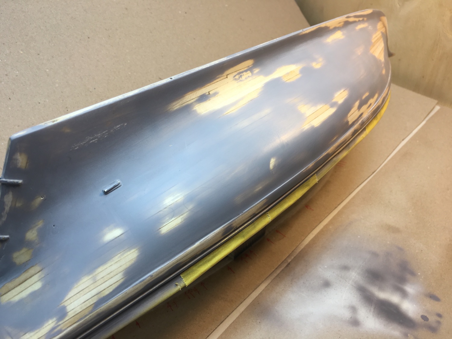
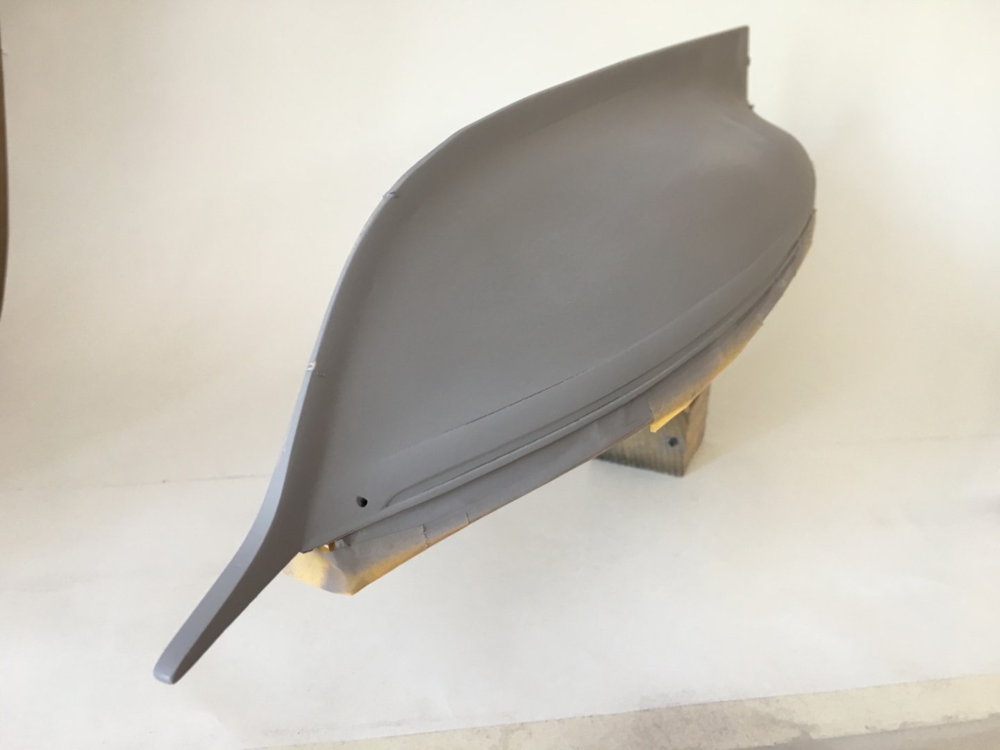
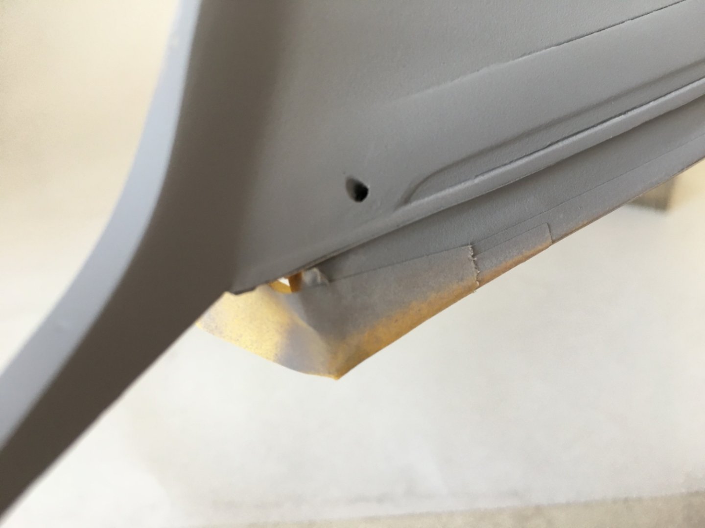
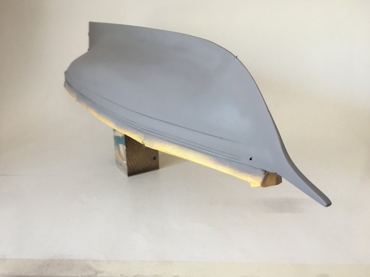
Although the propeller shaft logs were glued to their final location on the hull, propeller shaft struts and hawse pipes were kept aside and prime painted separately. Shaft log starboard side Shaft log port side Propeller shaft struts Hawse pipes The deck, upper mahogany transom , bulwarks and plank sheers (excluding outboard edges) were properly masked. After masking the mid deck with Tamiya masks, a wooden block was placed using double side stickers in order to hold the model safely in various positions. Commercial type grey primer was diluted with lacquer thinner with a ratio of 1:1. Paasche Single action bottom feed was used. 2-3 drops of retarder was added to each application bottle. Airbrushing was carried out with pressure around 1 bar. After the first coat several areas were filled with undiluted primer using a brush. After the curing period wet sanding was done with #800 grit paper. Here are some photos after first coat and sanding. Later 2 more coats were applied. Photos right after second coat. Starboard side Port side Stern Photos after final sanding of primer coats and removal of the masks. Starboard side Port side Black paint was lifted on one location of the bulwarks. This was probably due to inadequate adhesion of the paint and careless mask removal. However the surface cleanness-less and over smoothness of the surface were the factors to begin with. The paint lifted area was handled later with the black paint of the hull.


- 114 replies
-
- 3
-
-
- Pride of Baltimore II
- Model Shipways
- (and 1 more)
-
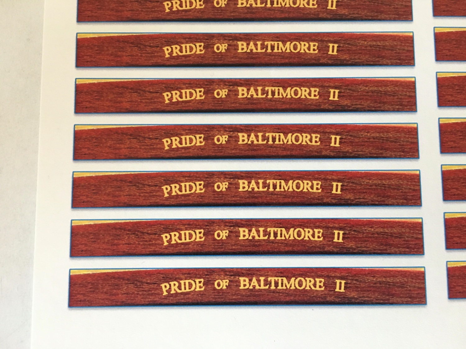
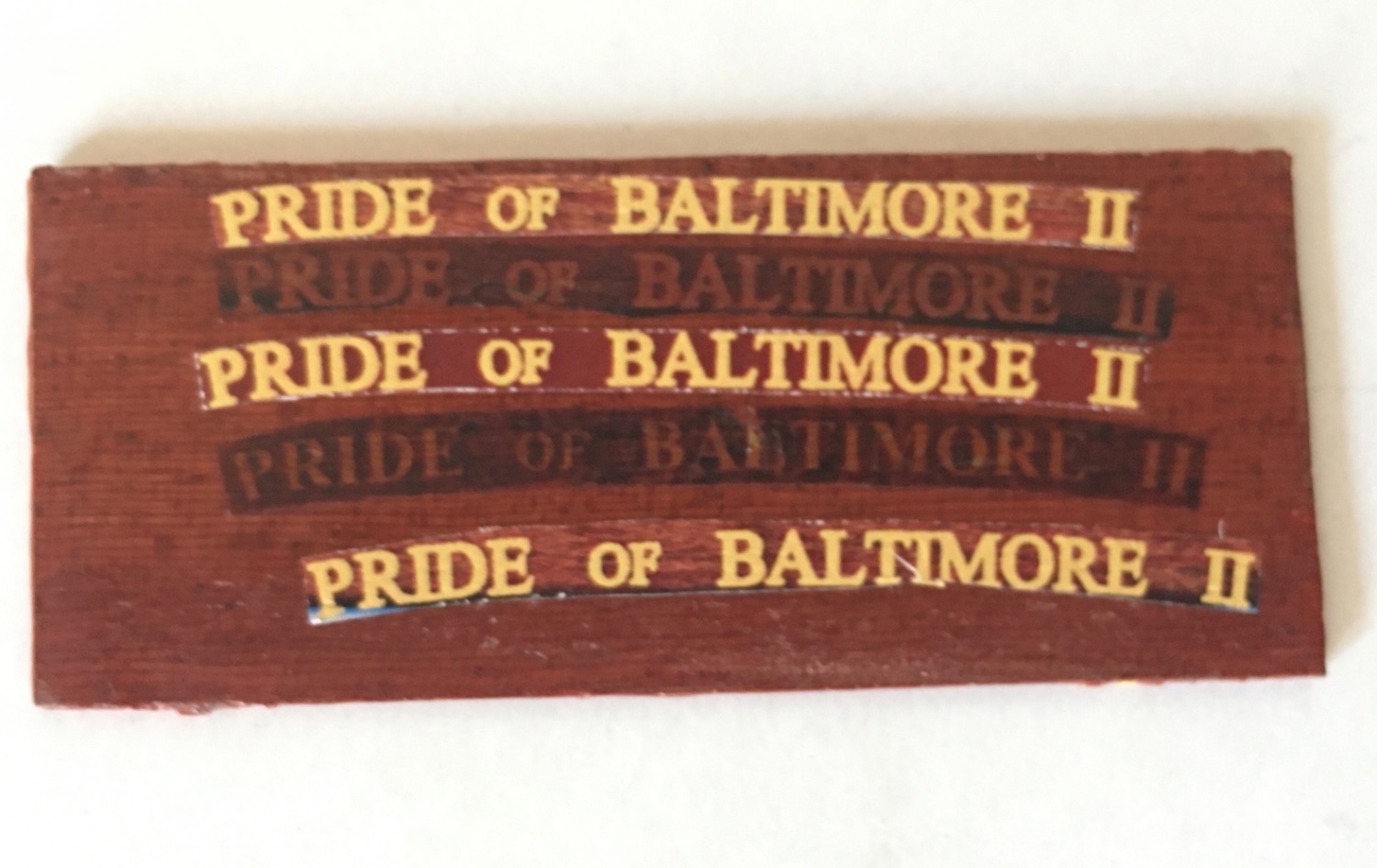
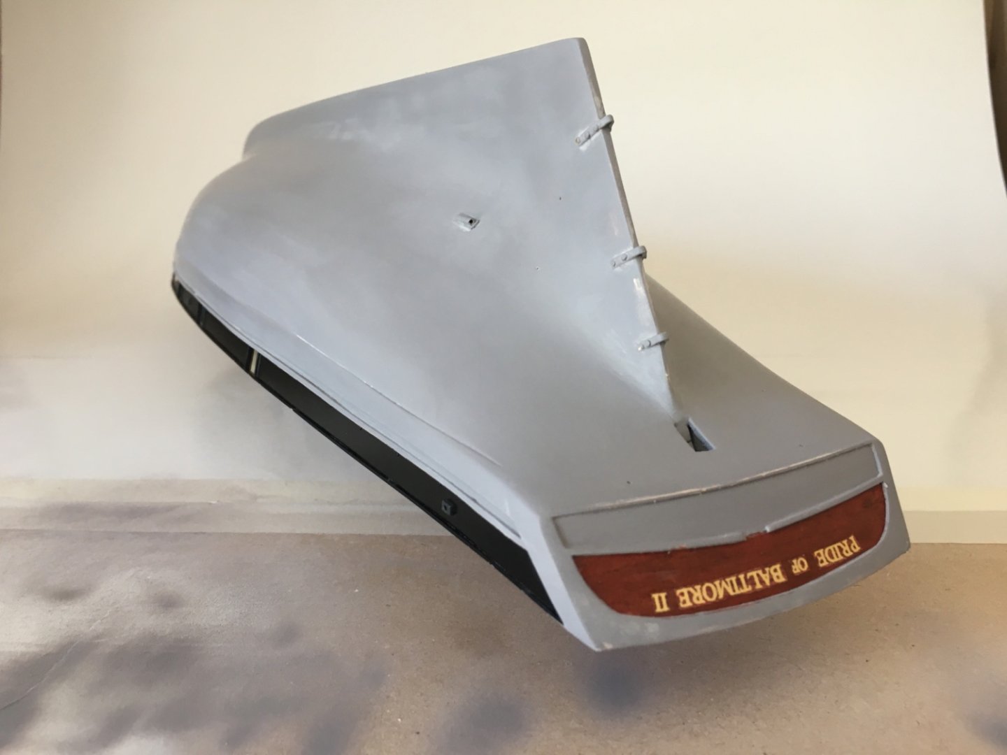
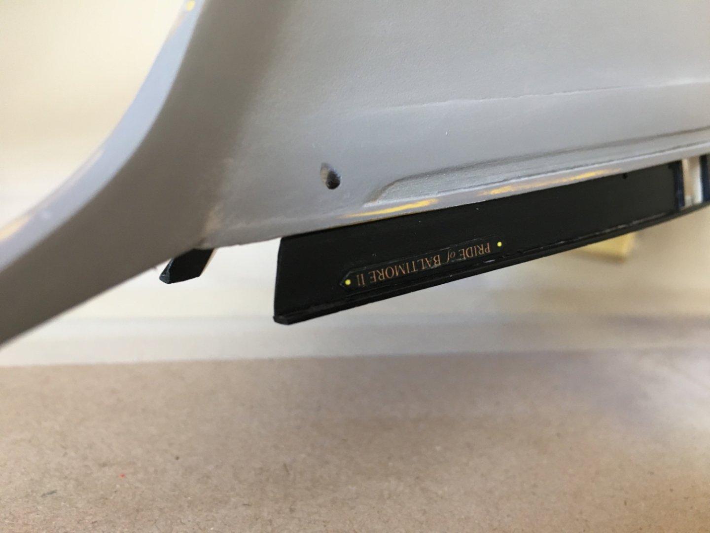
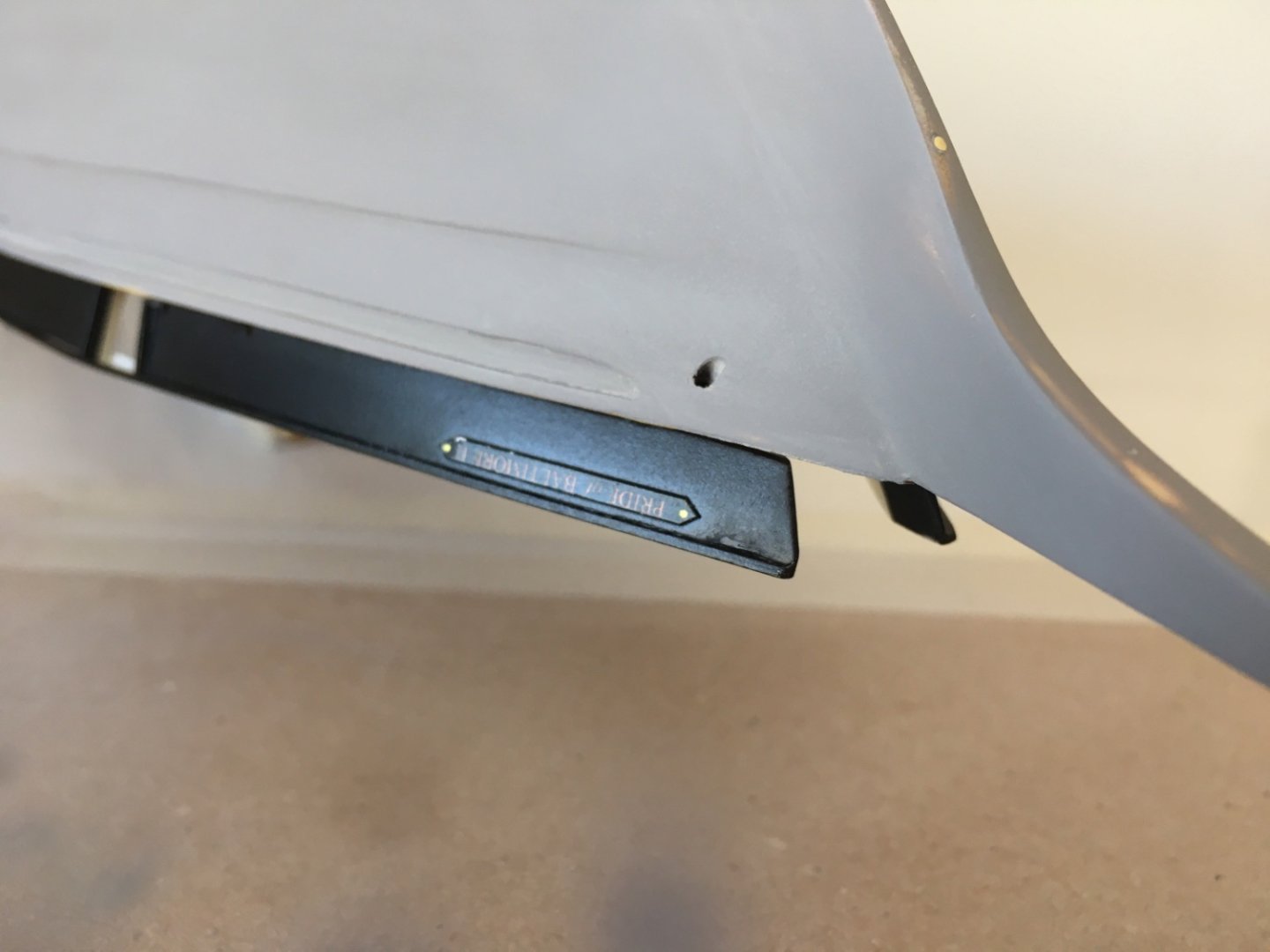
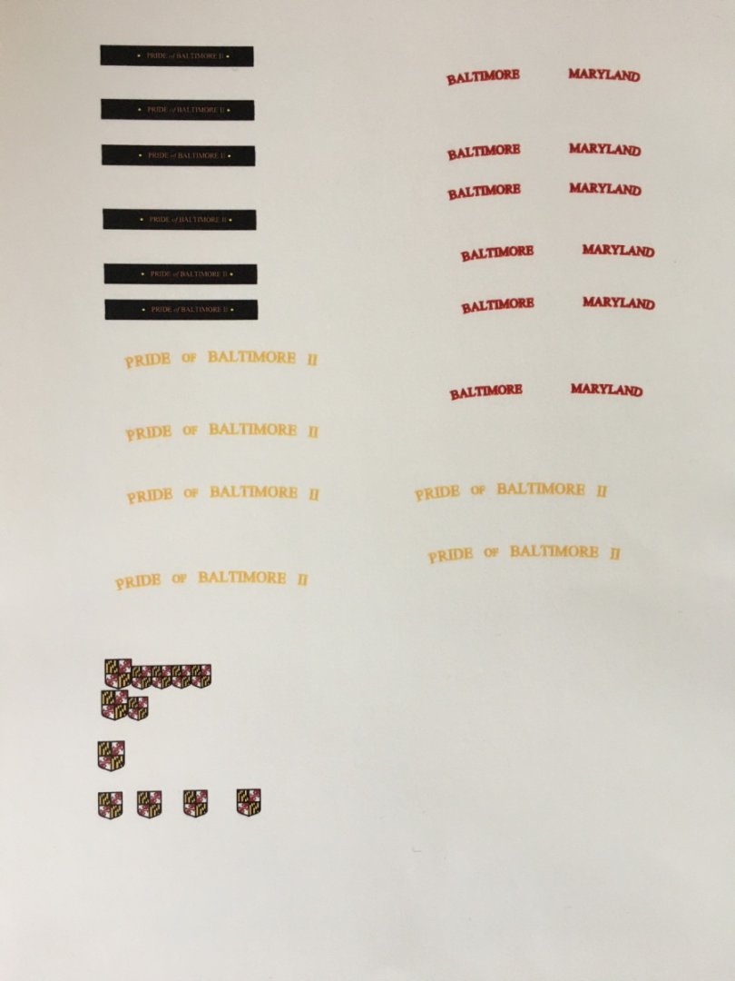
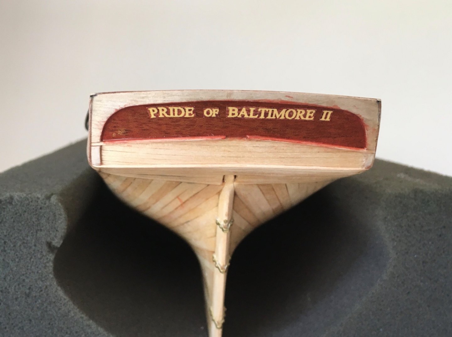
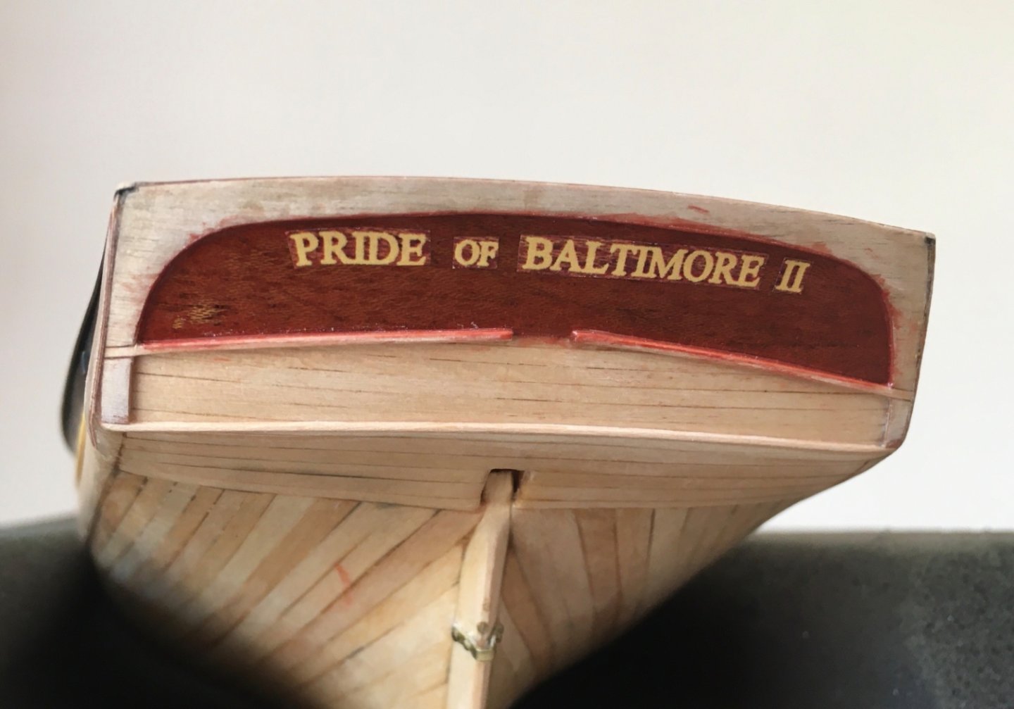
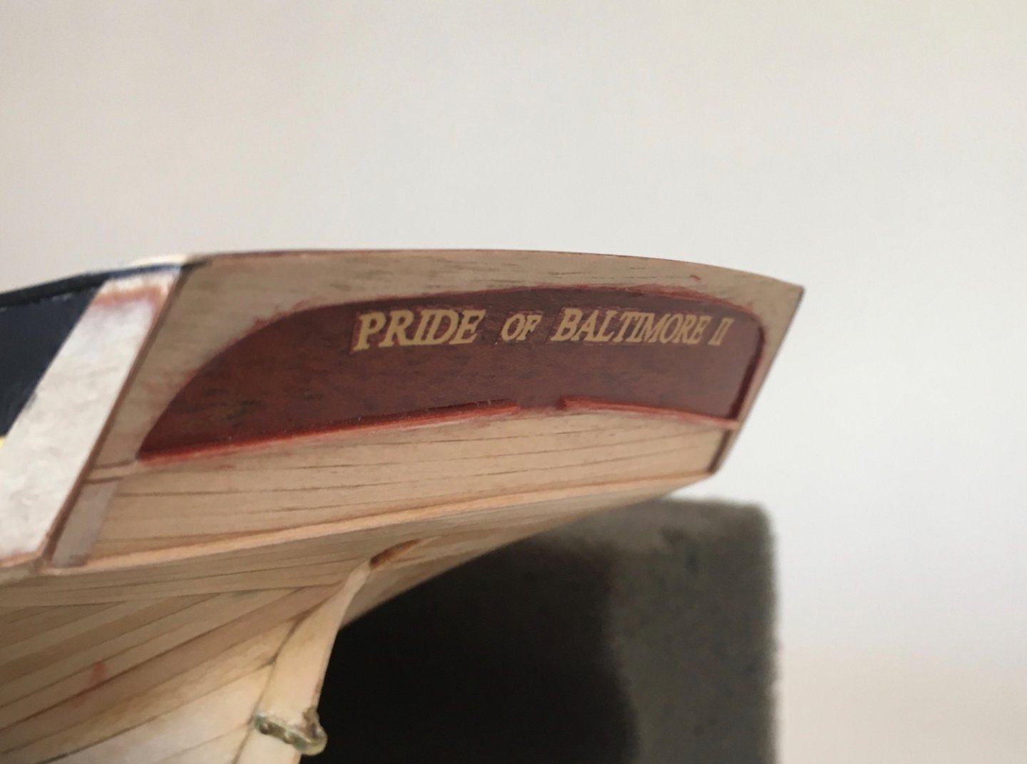
One last step before the primer coat of the hull was the handle the transom lettering. For 'Pride of Baltimore II' and ' Baltimore Maryland ' lettering I planned to prepare and apply decals. I prepared the lettering in a word file. Printout sizes and slightly curved lines were arranged according to measurements taken from the plans. The word file was then laser printed on transparent decal paper in the print shop. On the decal sheet you also see the bow lettering and small transom amblem. Both of their level was higher than their backgrounds and I used 300 gram photo paper for them later as you have already seen in the bow bulwark lettering. 'Pride of Baltimore II' lettering was gold in color to be placed on mahogany background. ' Baltimore Maryland ' lettering was red in color to be placed on yellow background. When I tried to test a 'Pride of Baltimore II' decal I quickly observed the light gold color is lost on the dark mahogany background. There was no problem with the ' Baltimore Maryland' decal as it was dark color (red ) on light background (yellow). I planned to visit the print shop and get printout on an opaque (white) decal paper. However there must also be solution for the hallow areas in letters like p, d, o or b. I found a solution as follows. I took a photo of the mahogany transom area. Than I combined this photo with 'Pride of Baltimore II' lettering in Word program. The word file was used again the print shop but this time to an opaque (white) decal paper. Here is a test application. Rows 2 and 4 are transparent decals. Here the problem was to deal with the white edges of the decal. The white edges have to be dark colored preferably before the final decal placement. After carefully cutting the lettering the edges were colored and the decal was put aside to dry. Then it was applied to the prepared surface. This time I decided to apply mahogany stain to upper transom. followed by sanding sealer coats. After 2-3 clear gloss varnish the surface was ready for decal application. To minimize the pattern difference between decal and backround, I cut the words and placed each of them separately . Here are some photos of the upper transom lettering. After the gloss and final satin varnish coats which were to be applied in the later steps, the lettering will look much more acceptable.


- 114 replies
-
- 4
-
-
-
- Pride of Baltimore II
- Model Shipways
- (and 1 more)
-
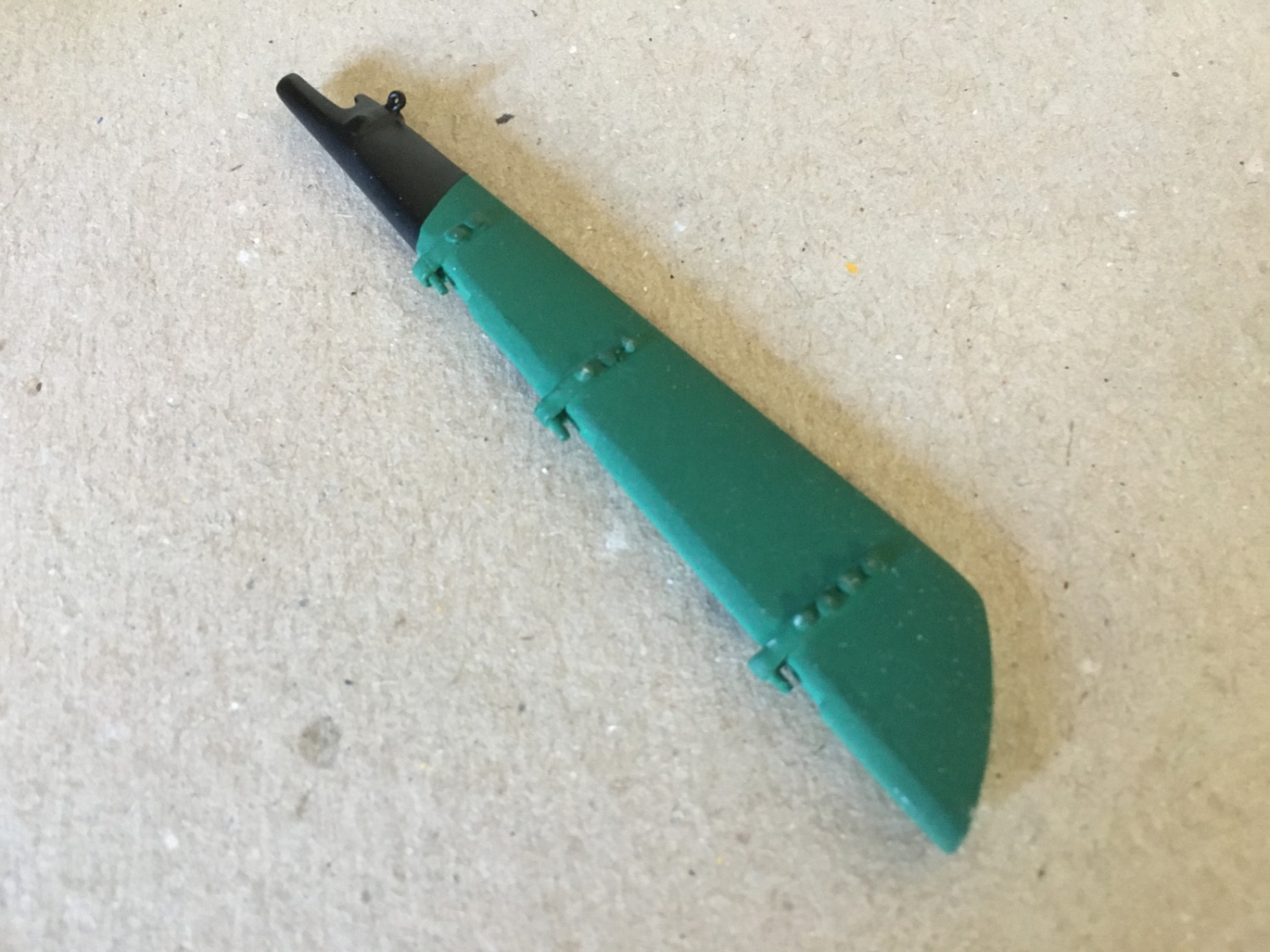
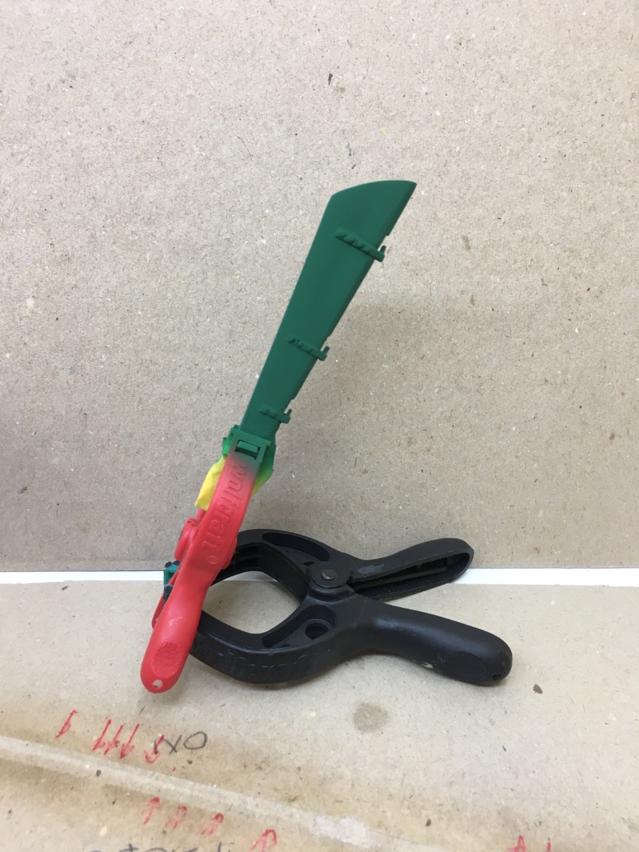
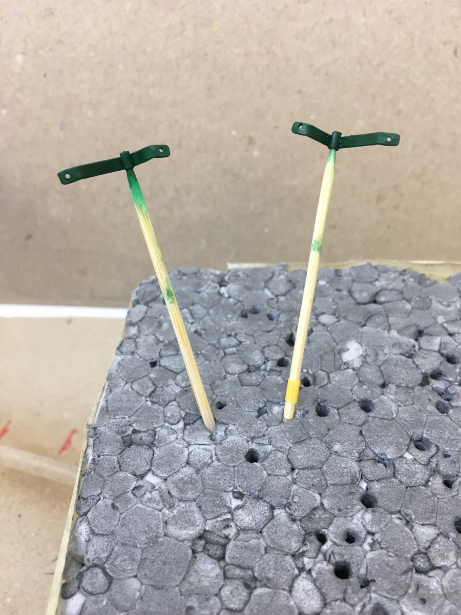
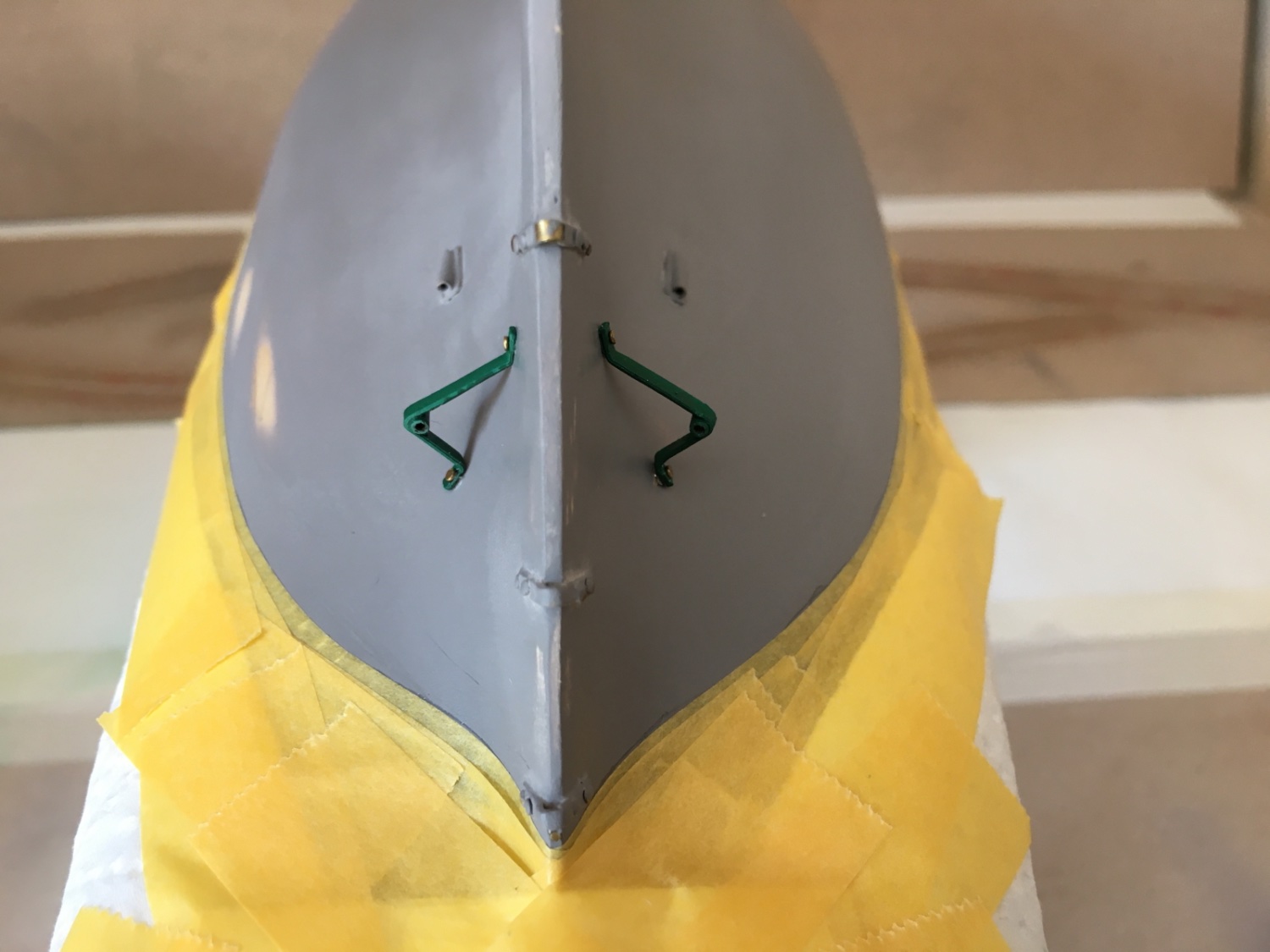
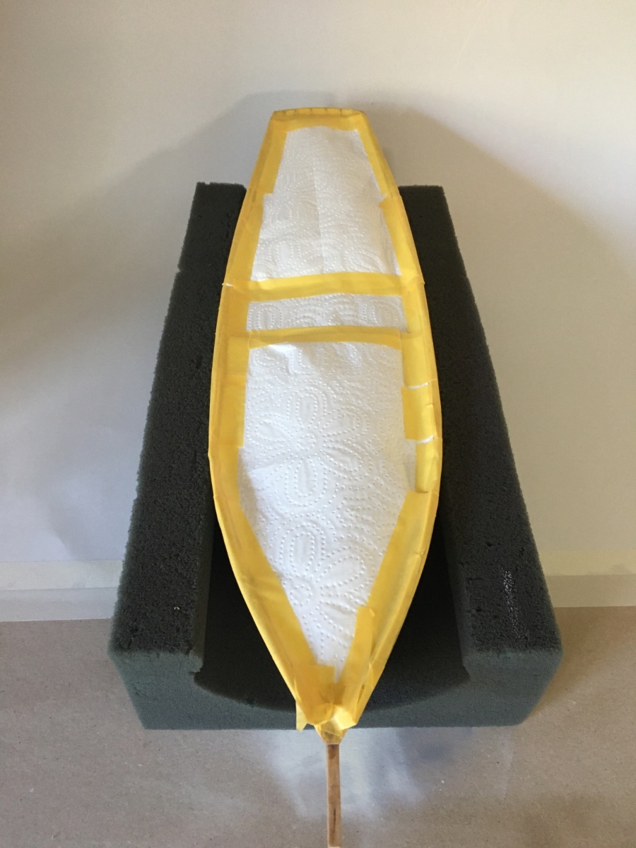
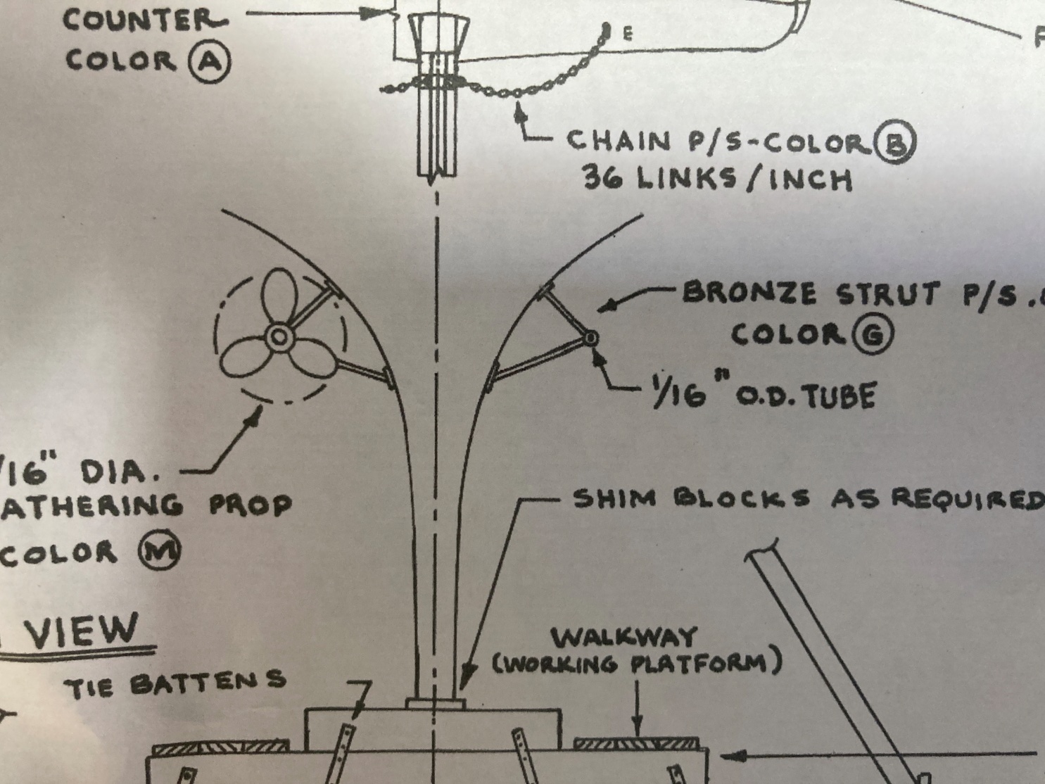
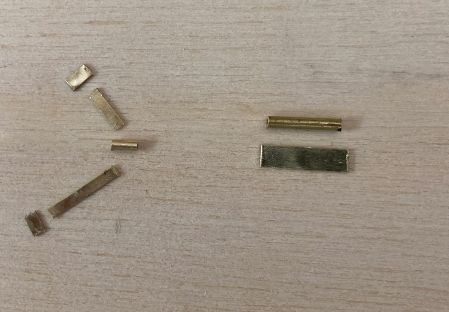
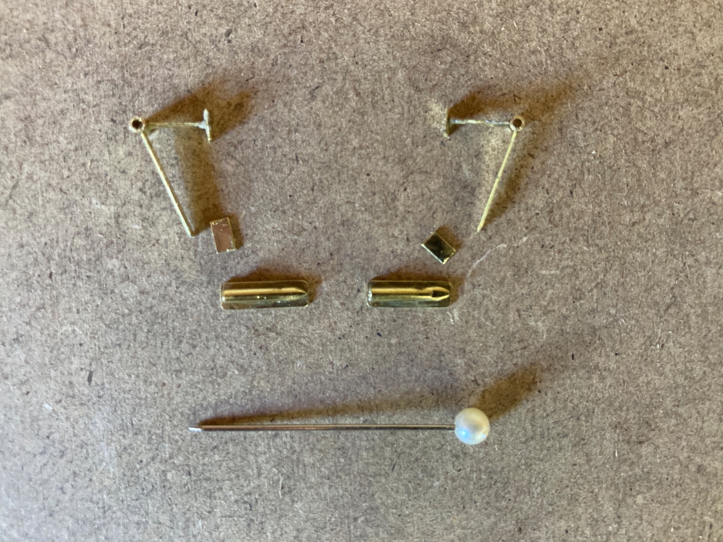
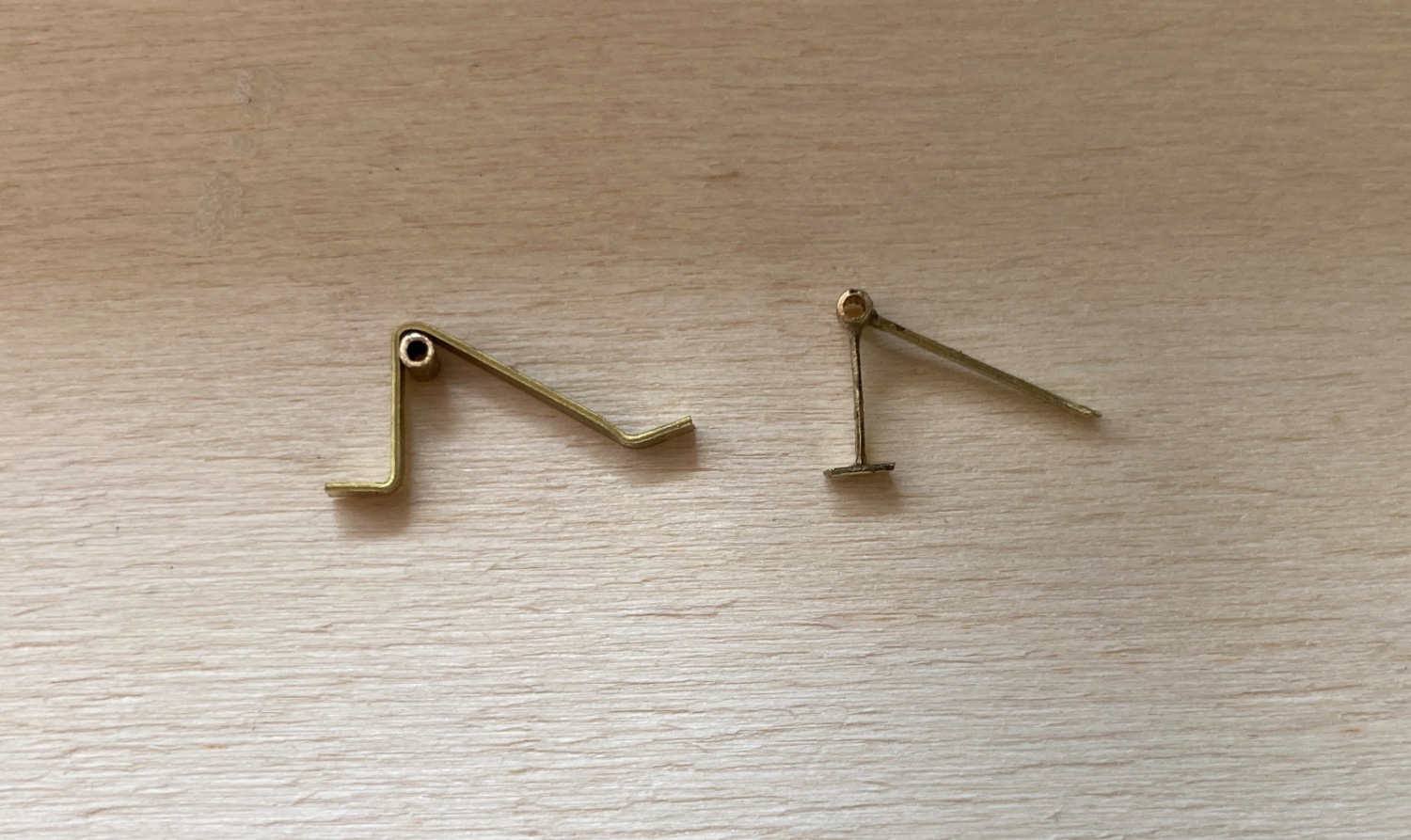
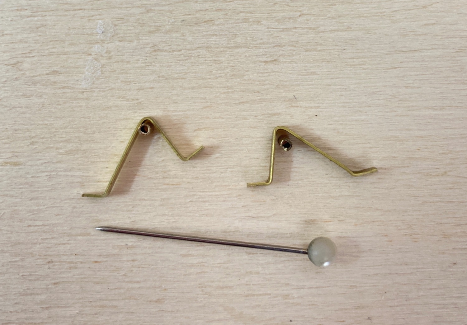
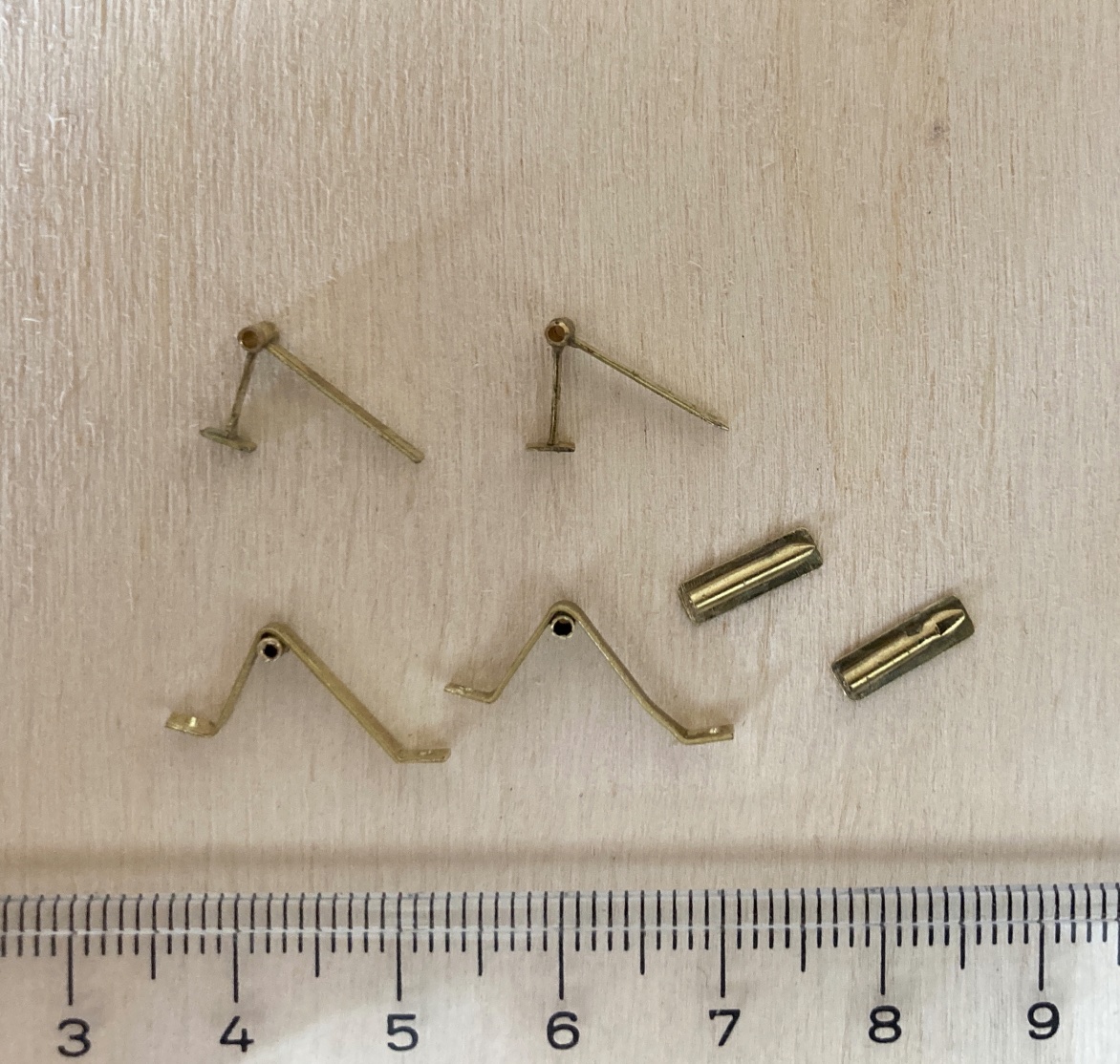
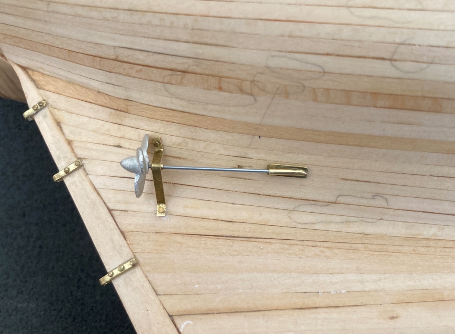
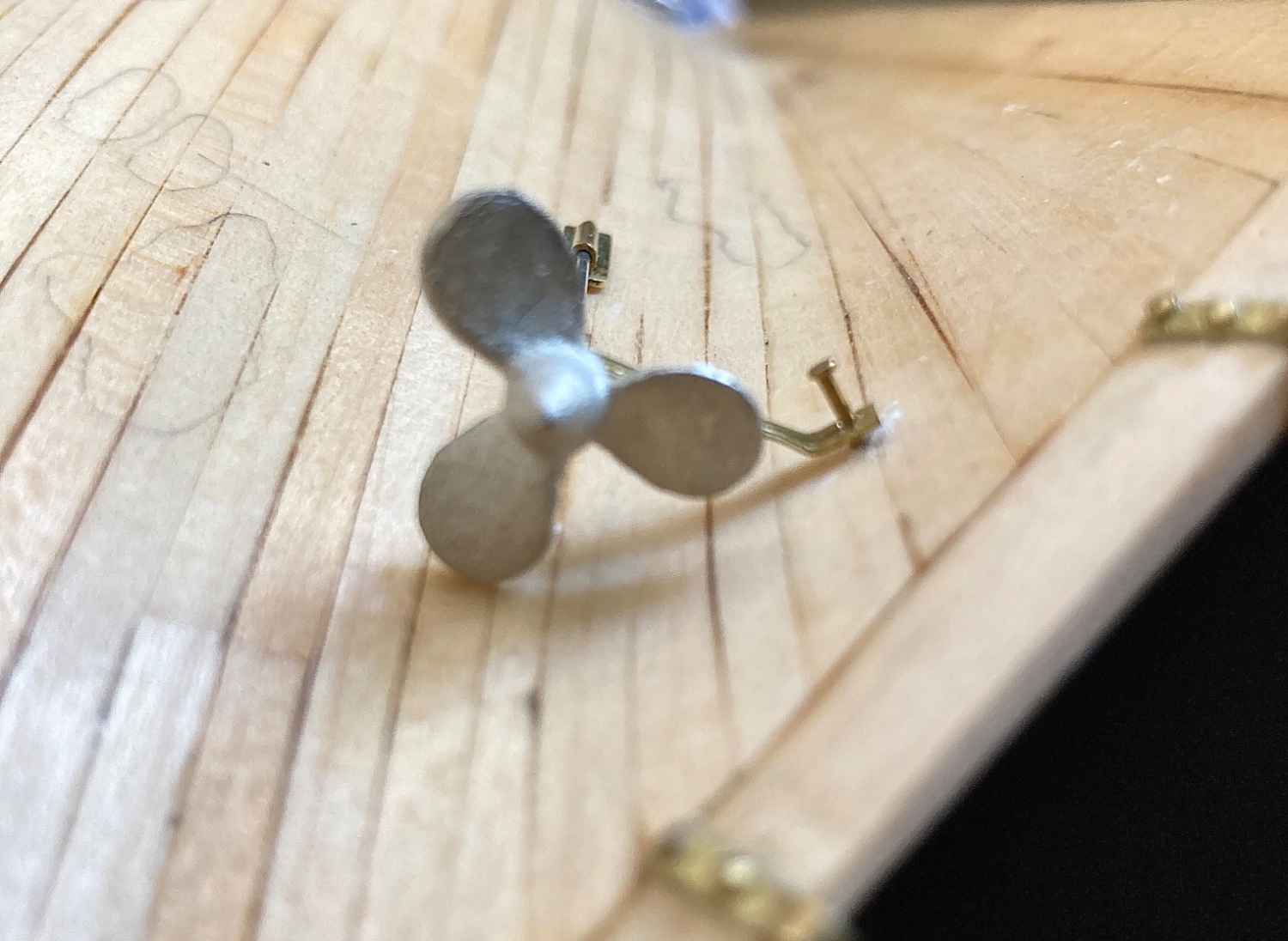
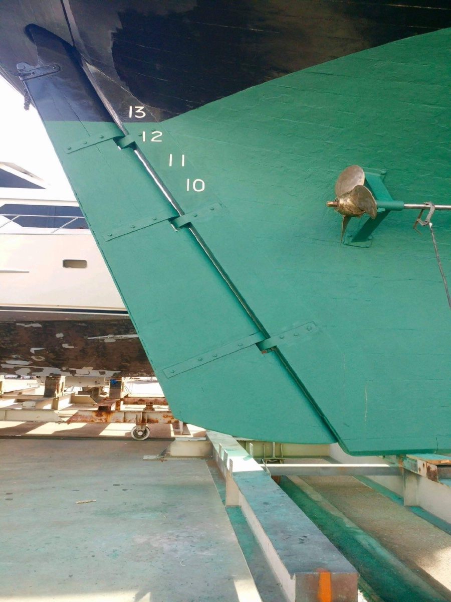
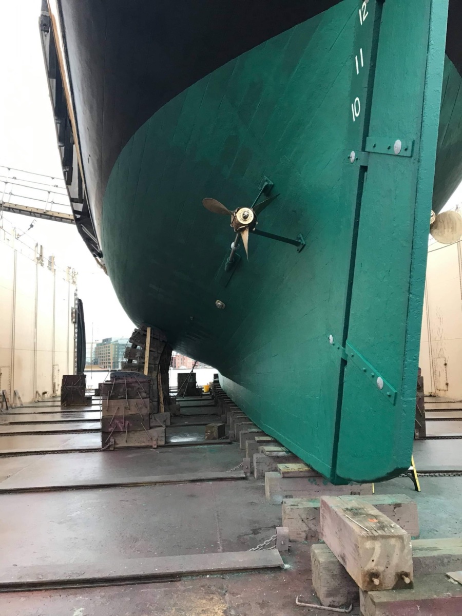
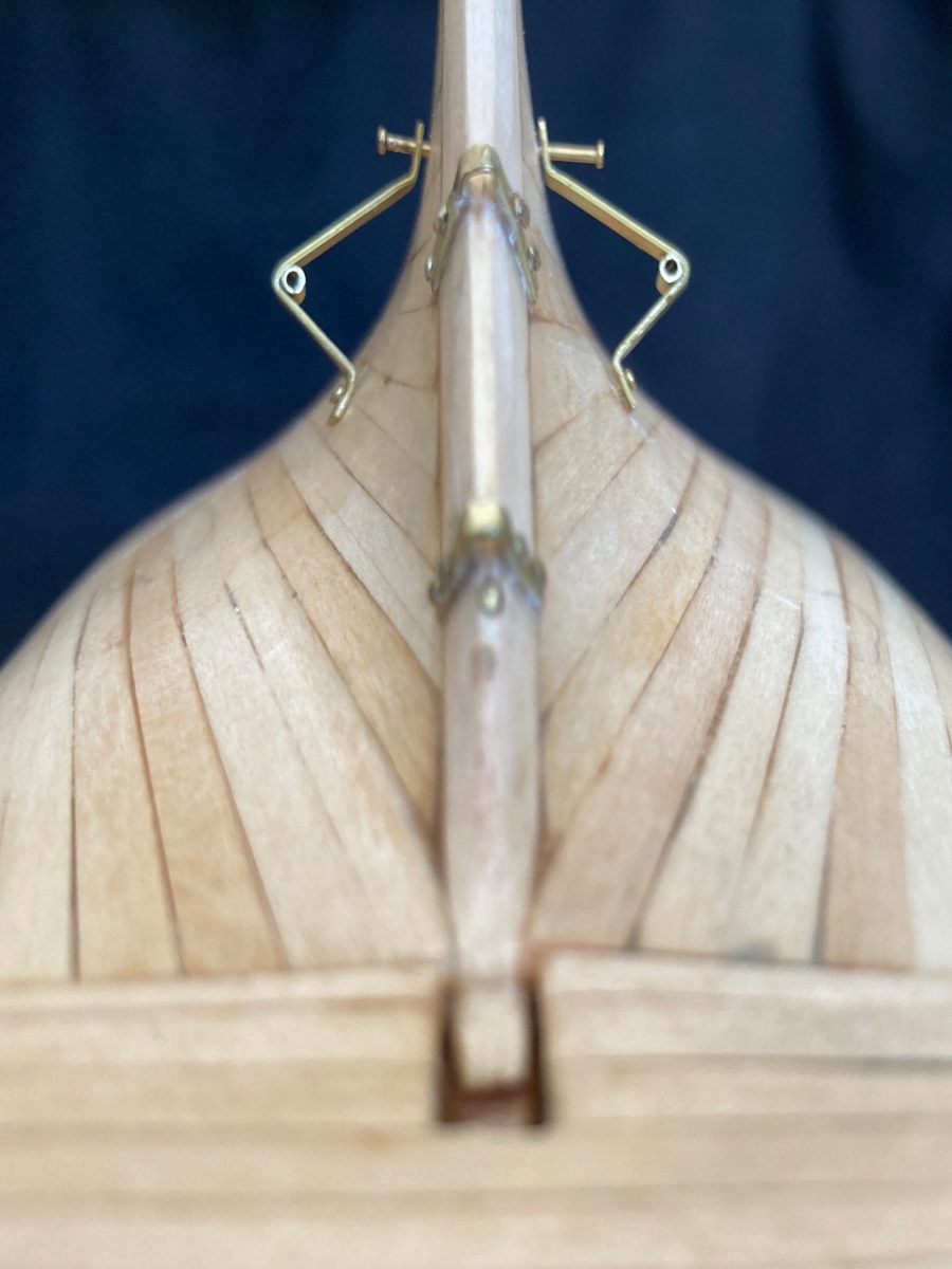
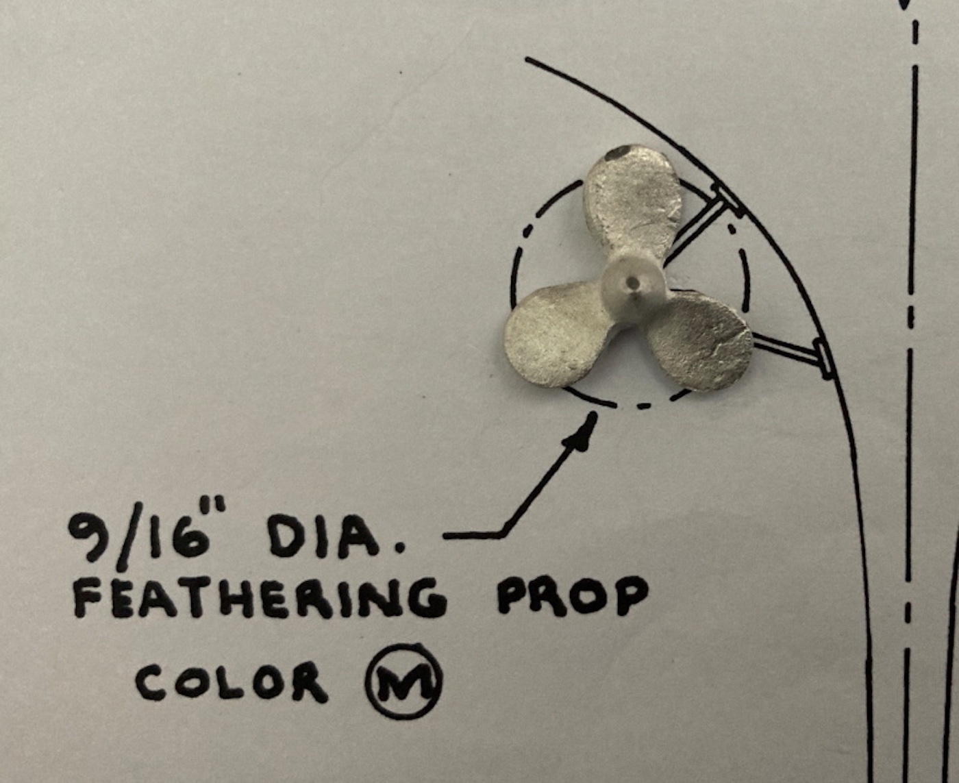
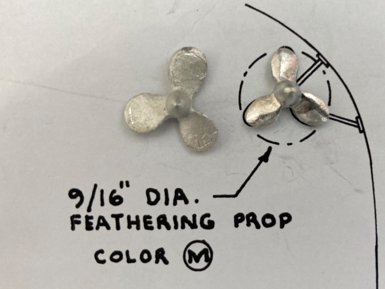
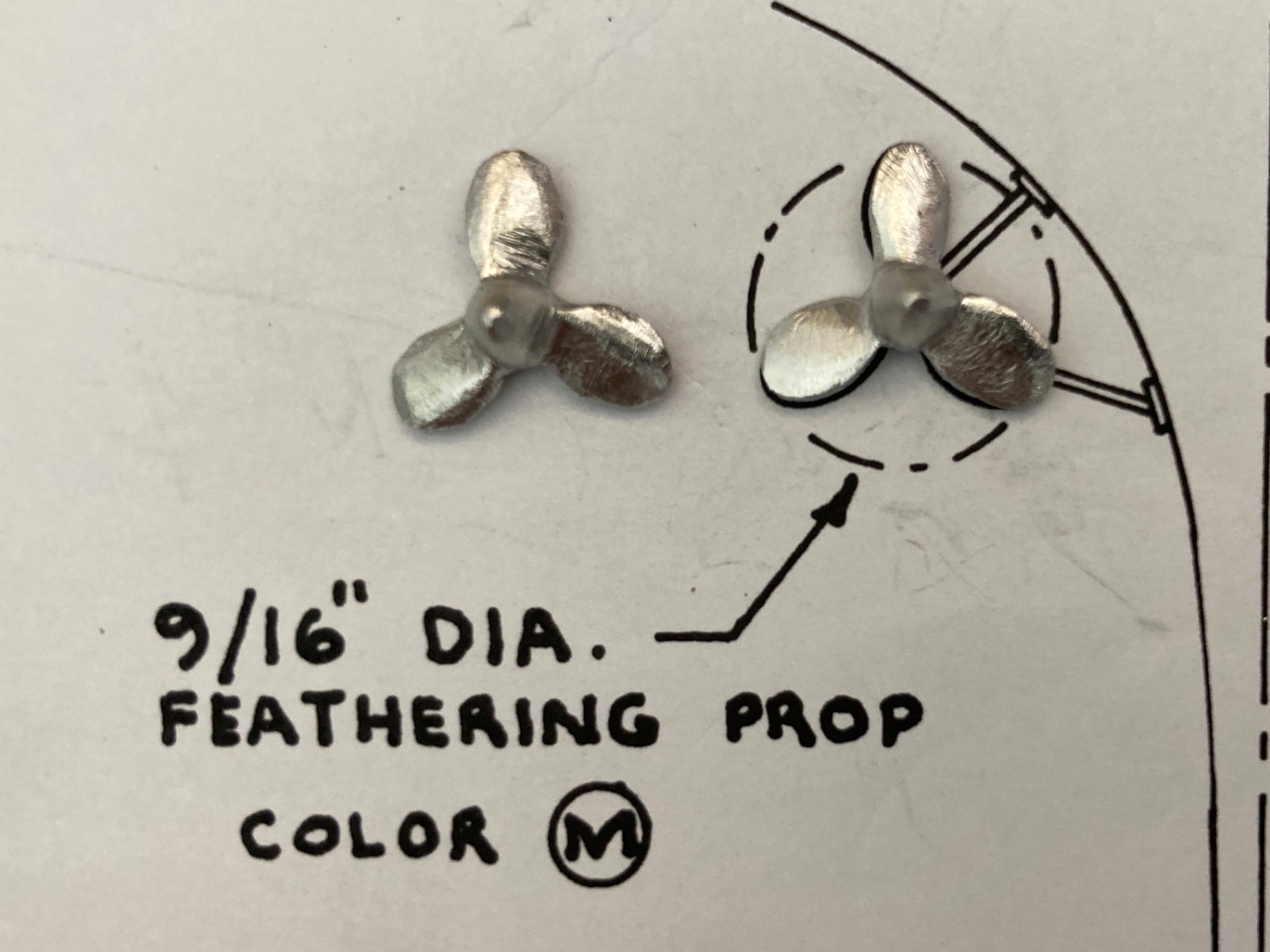
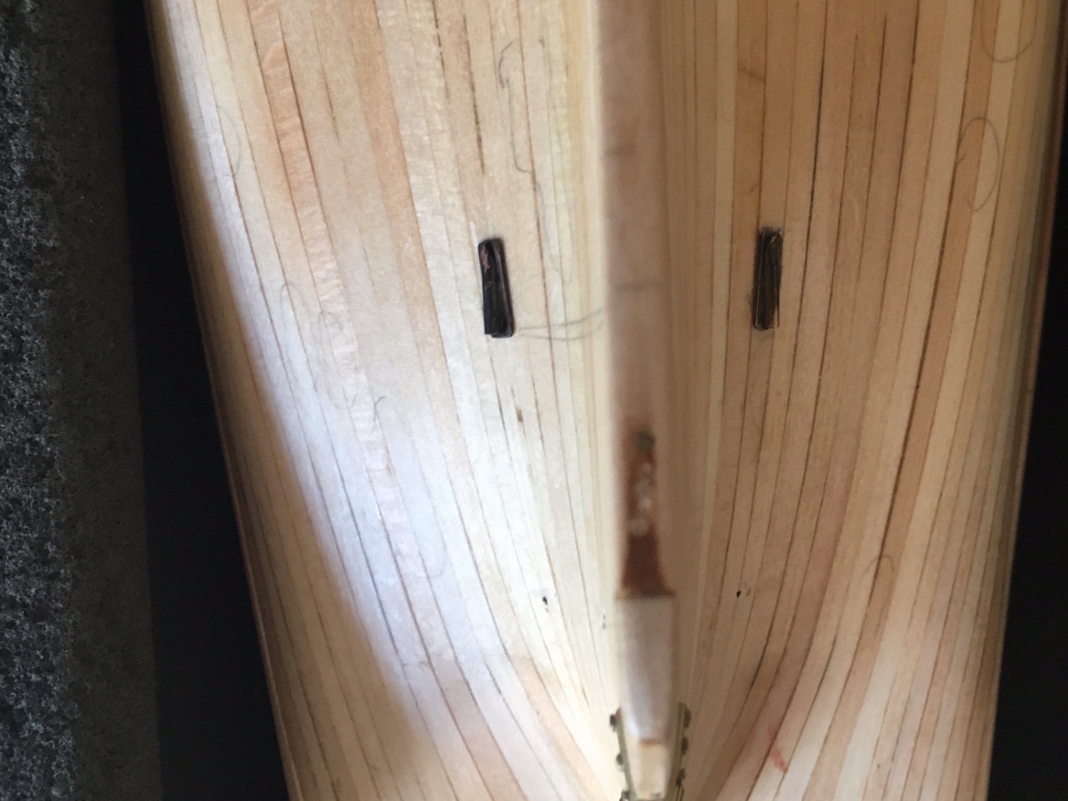
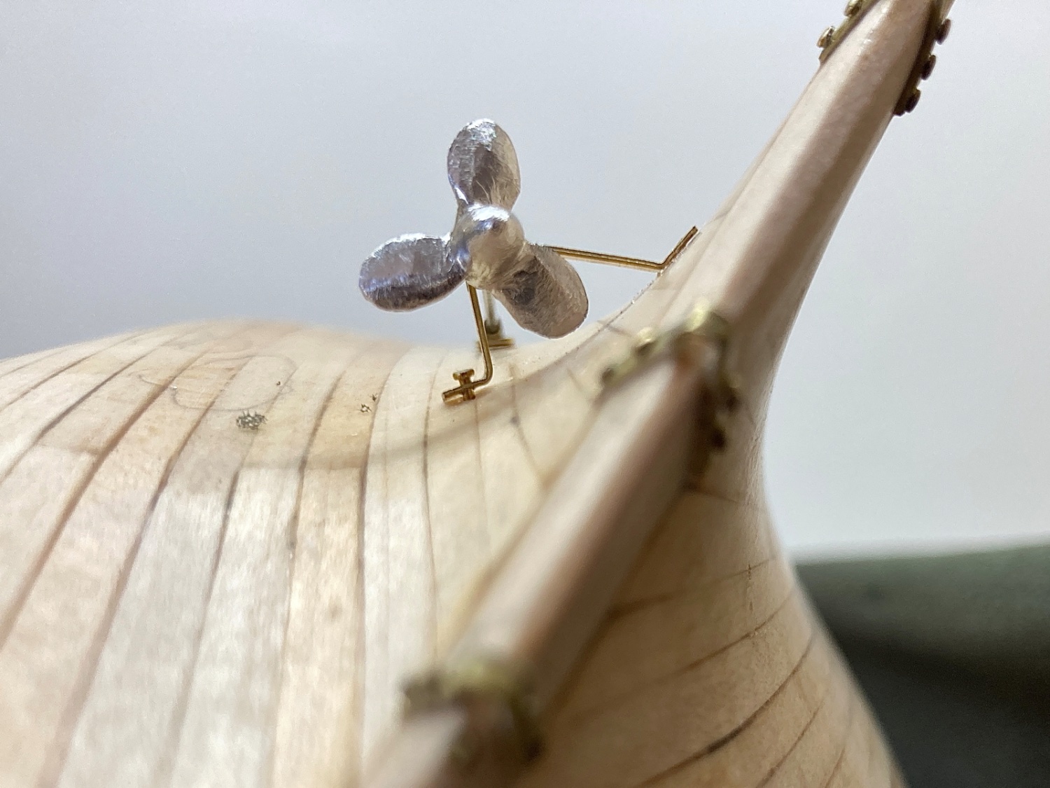
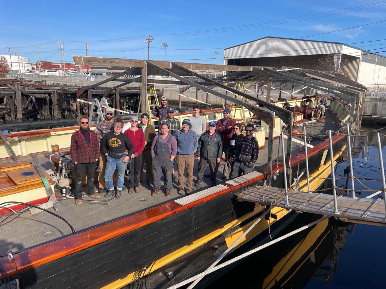
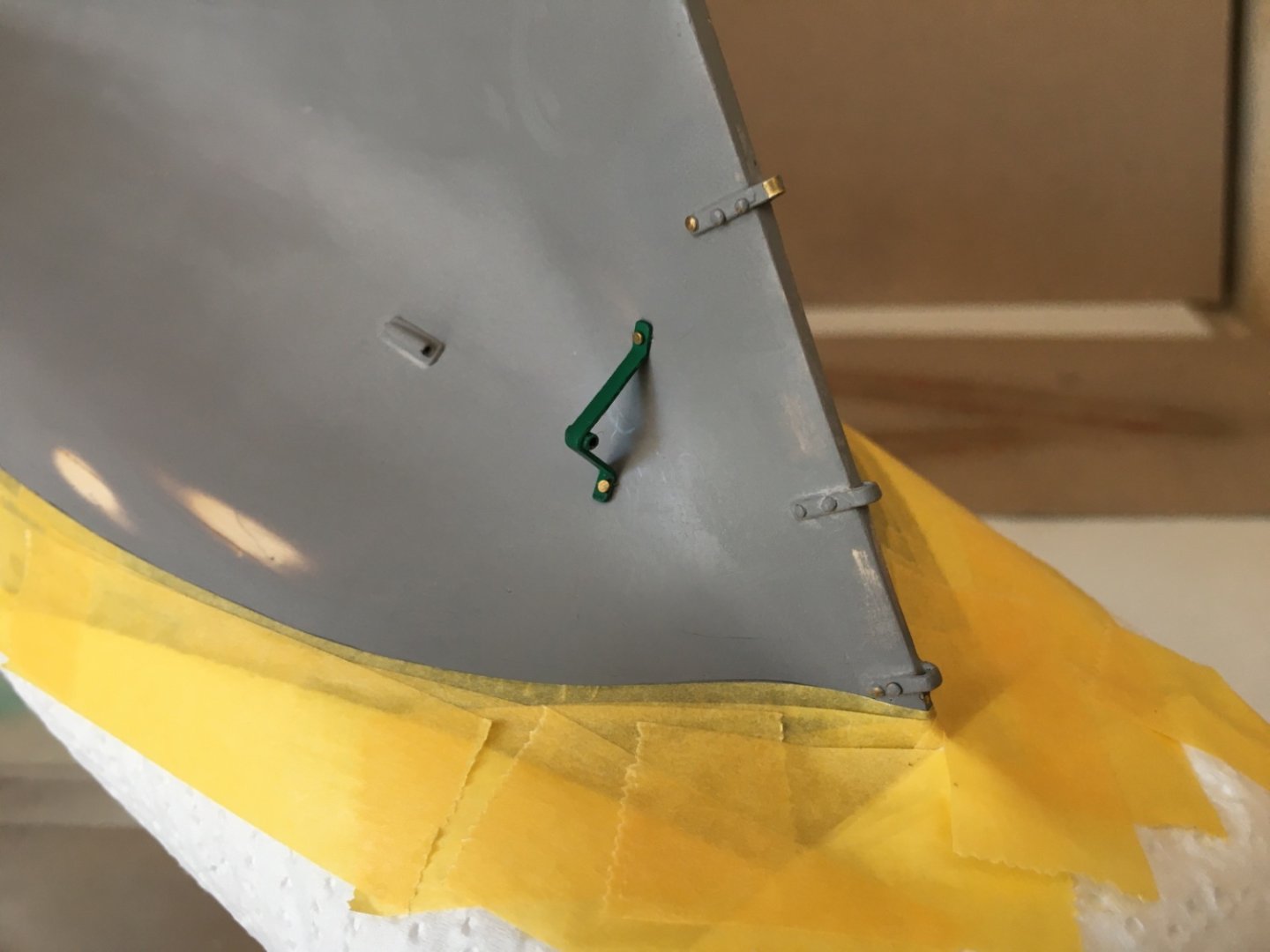
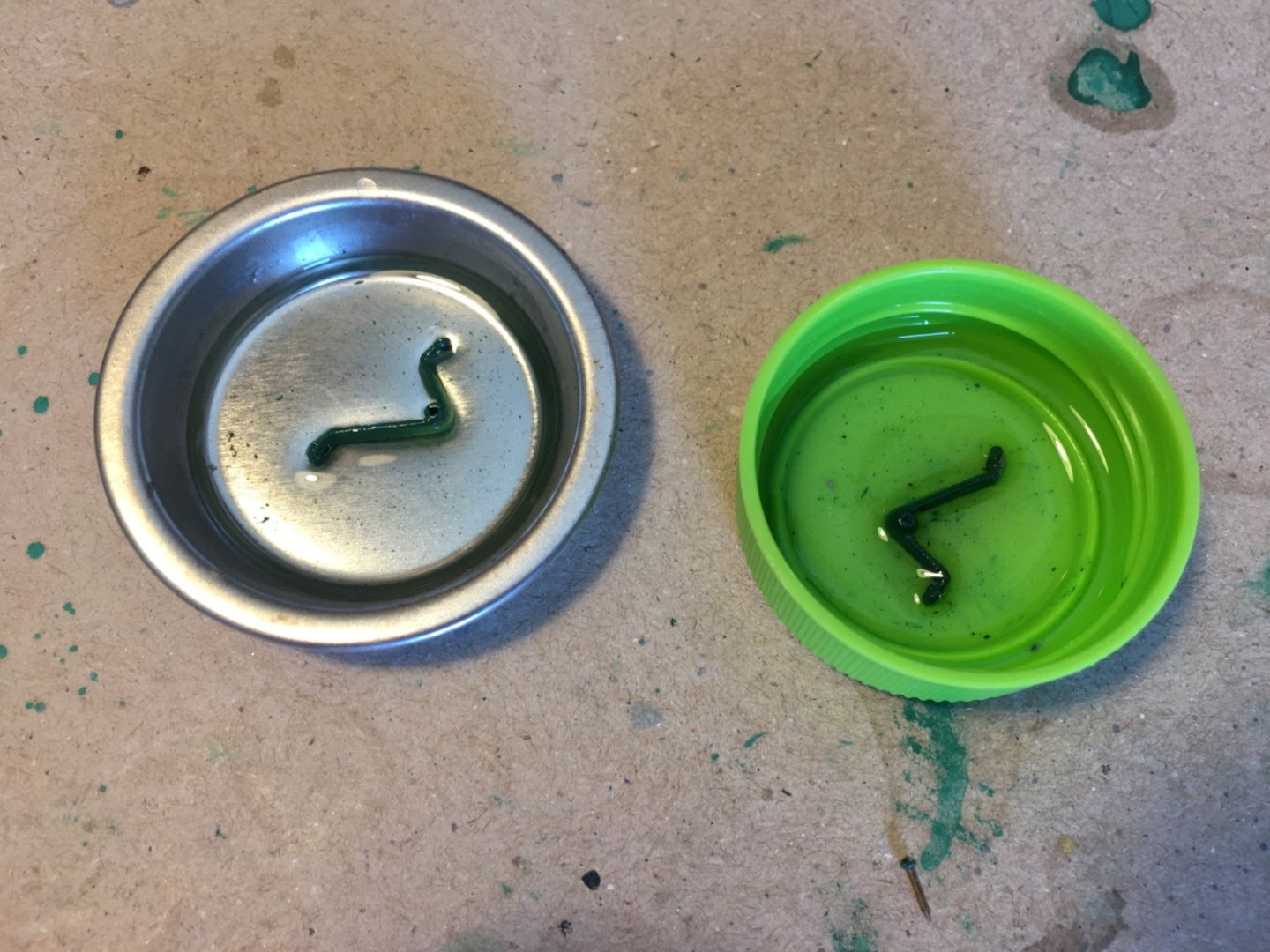
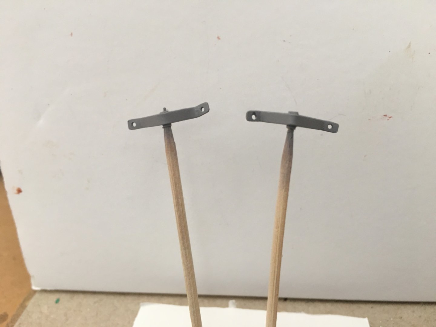
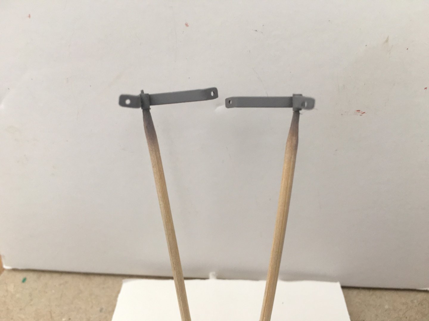
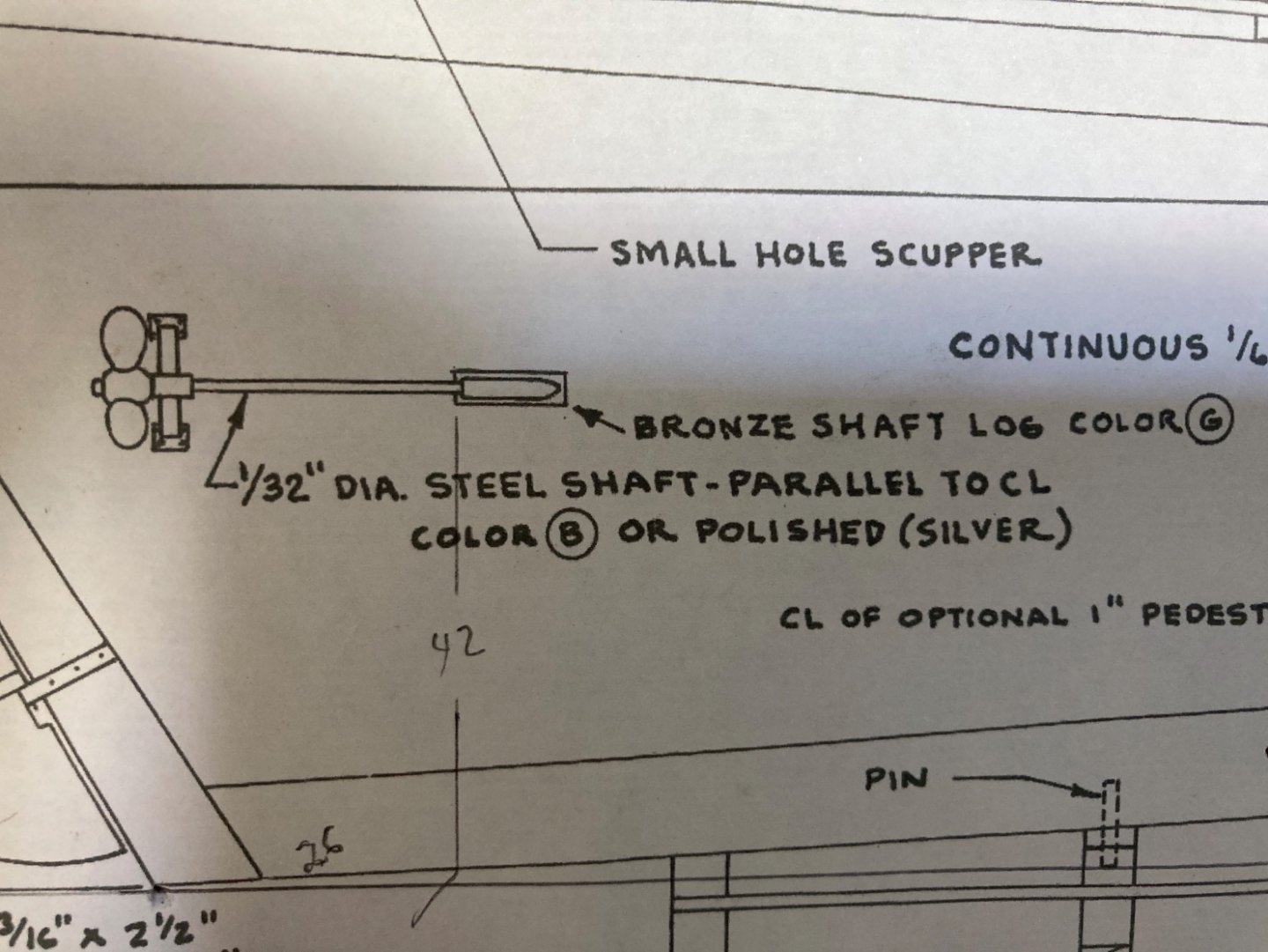
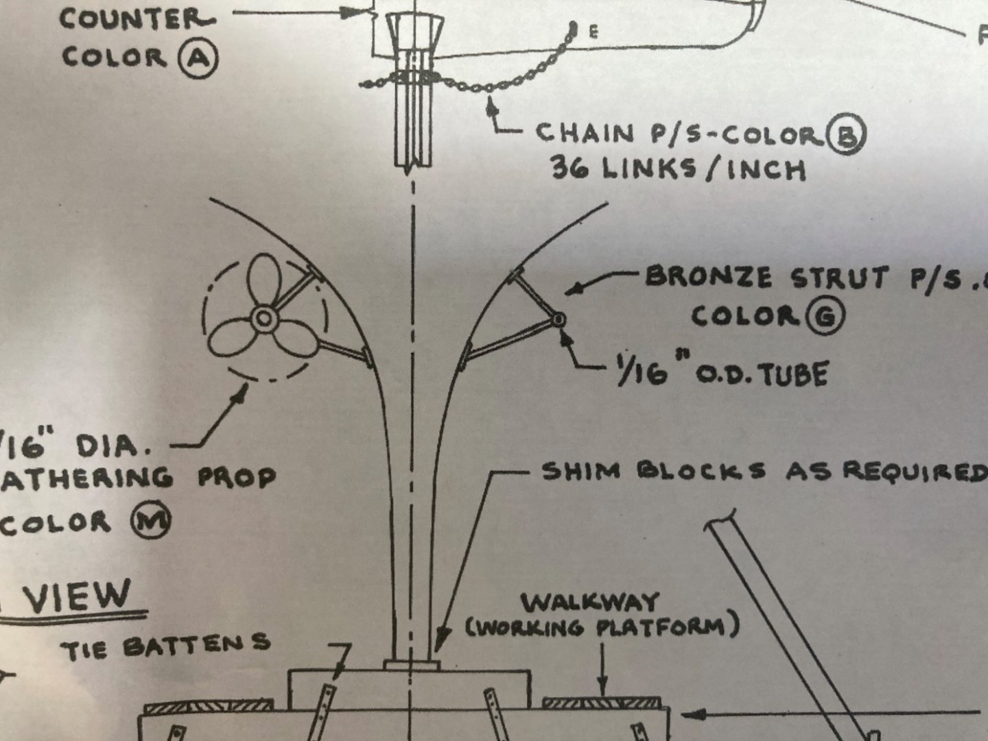
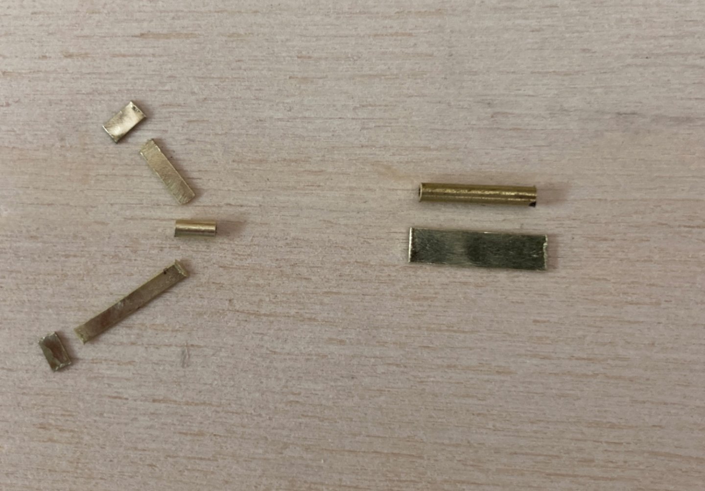
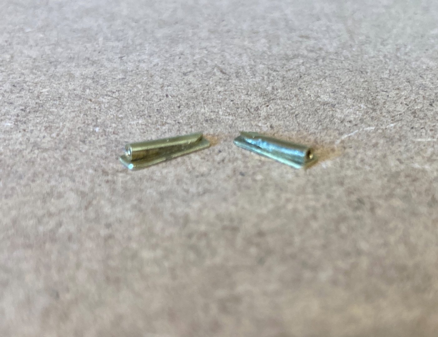
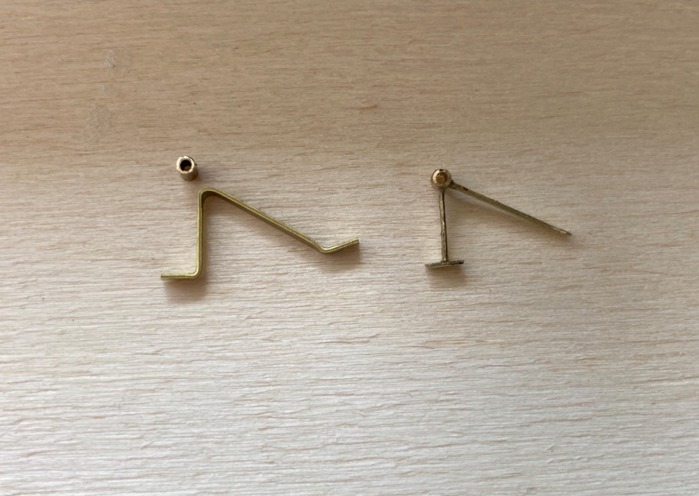
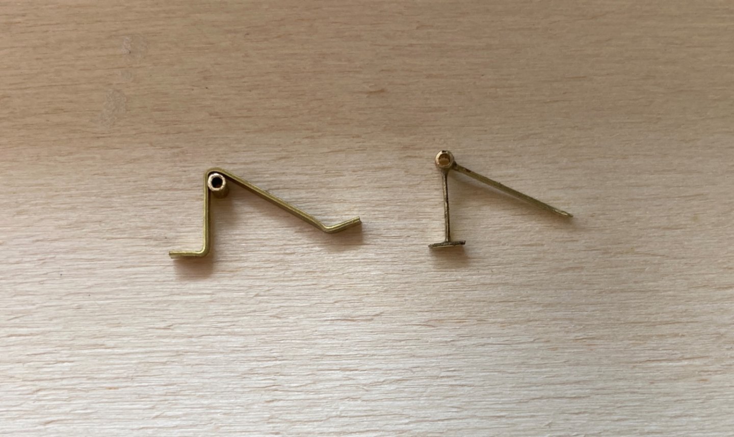
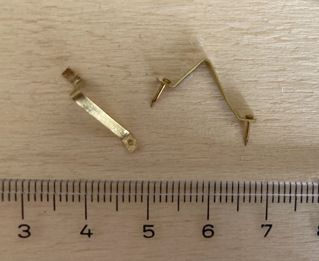
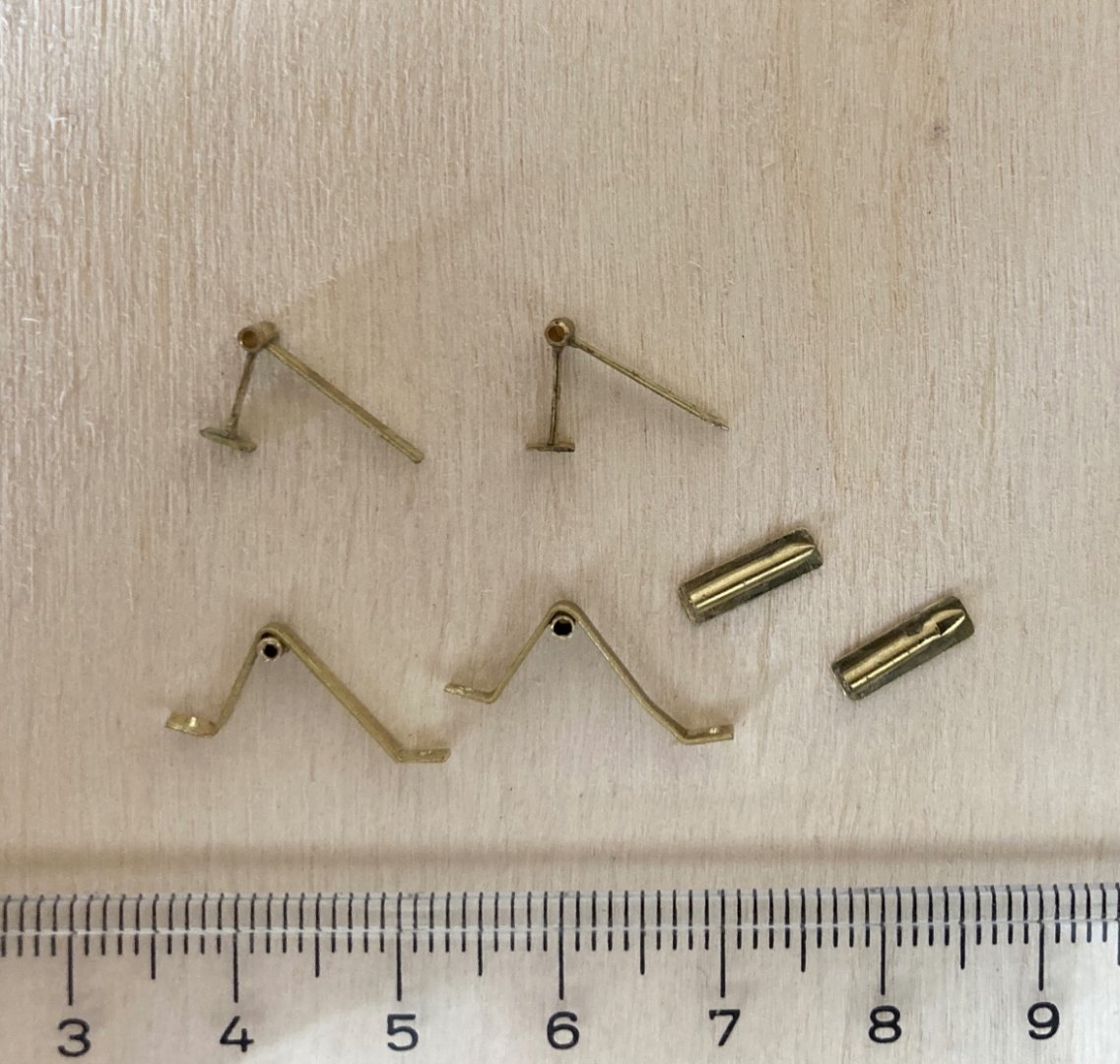
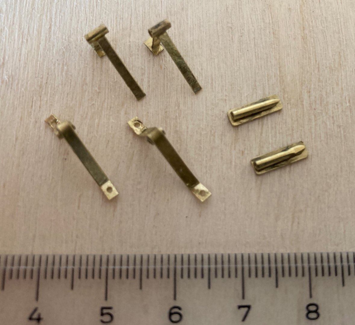
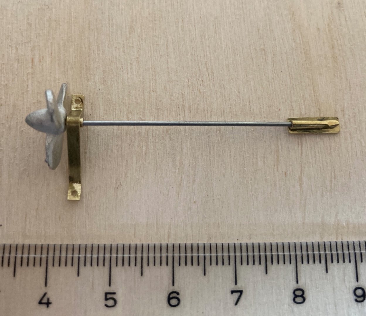
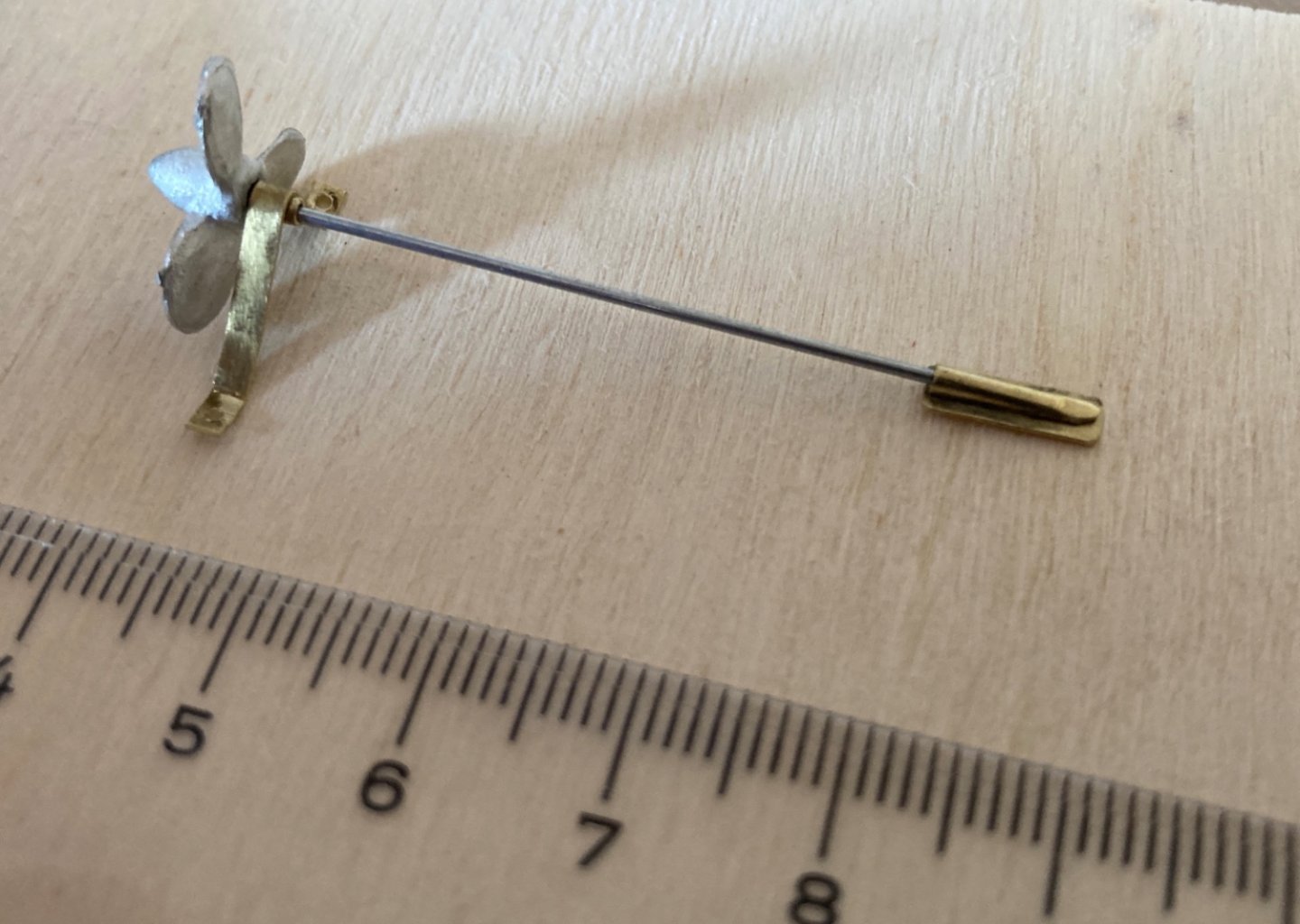
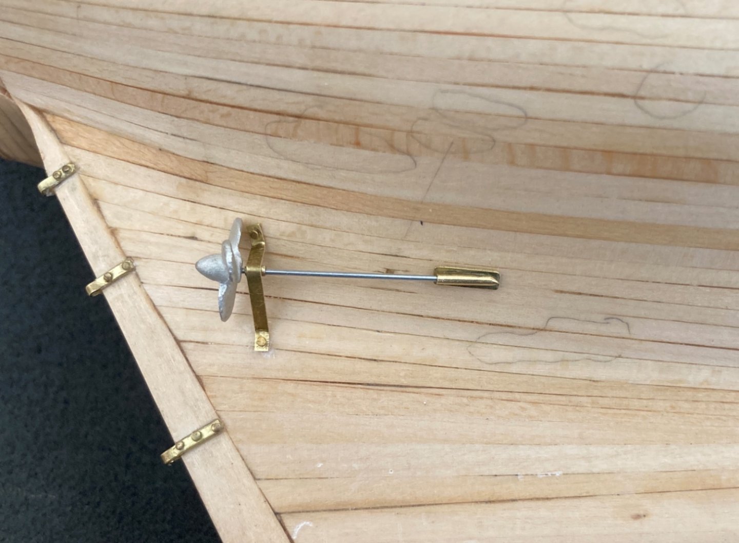
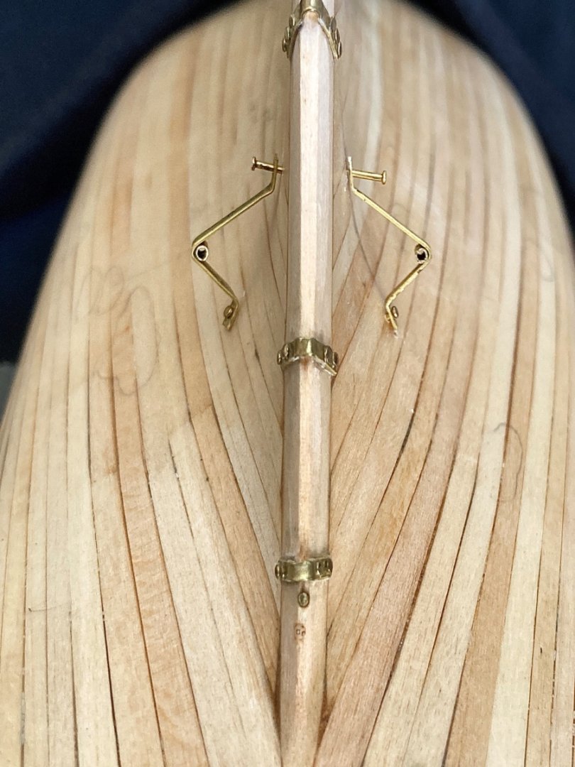
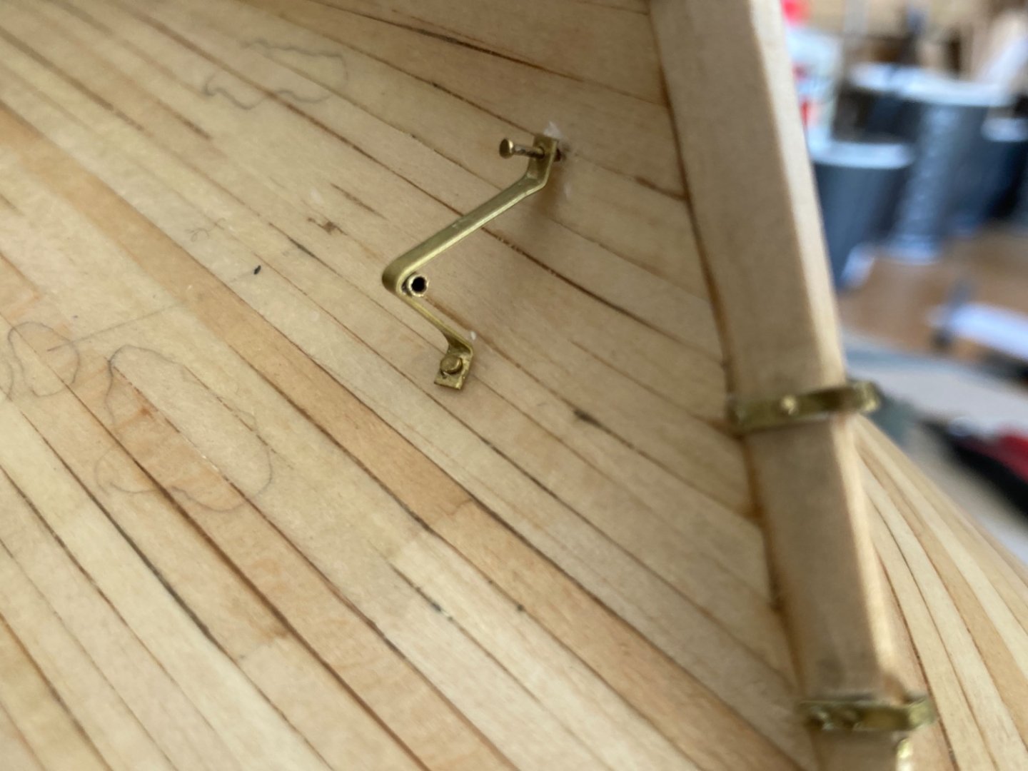
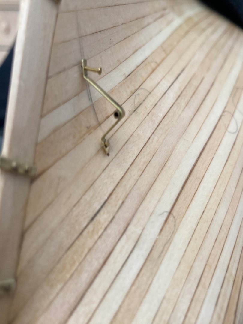
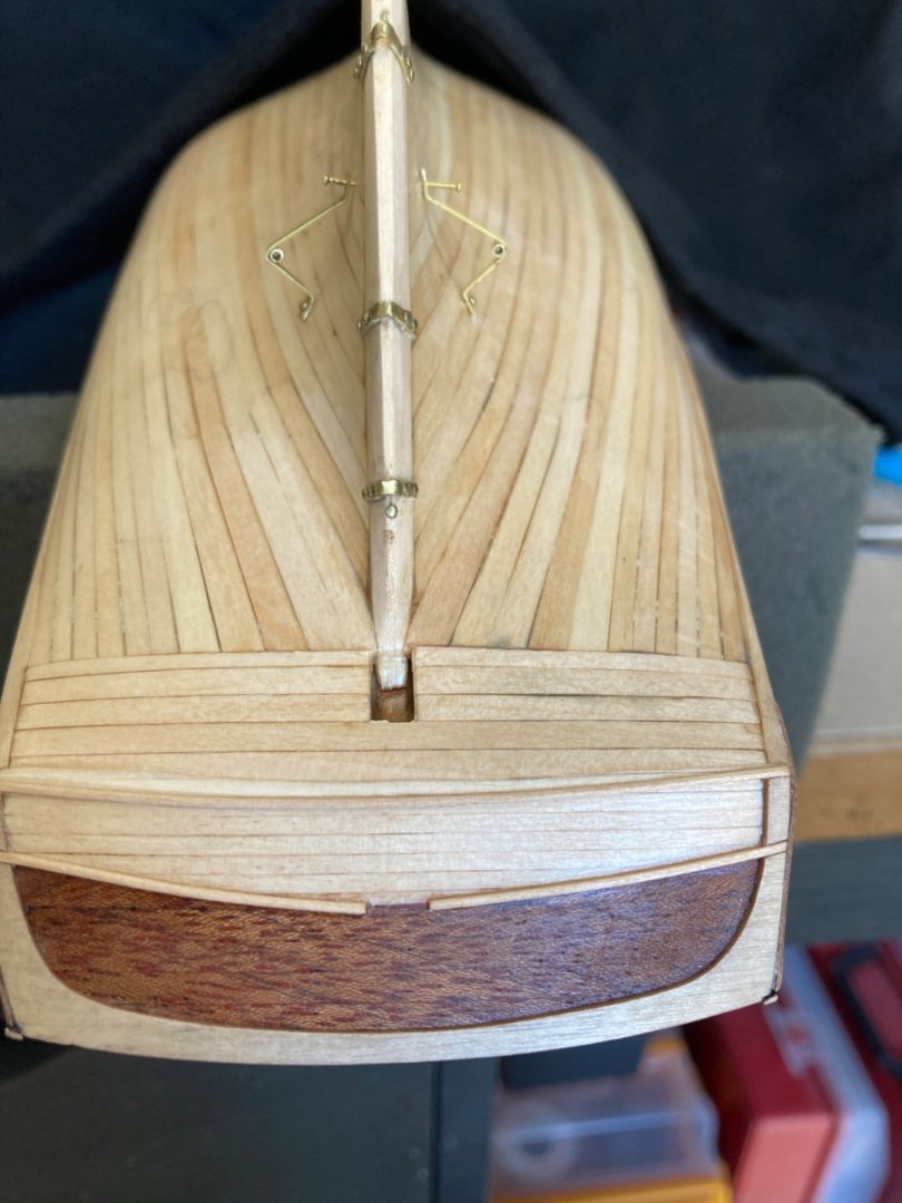
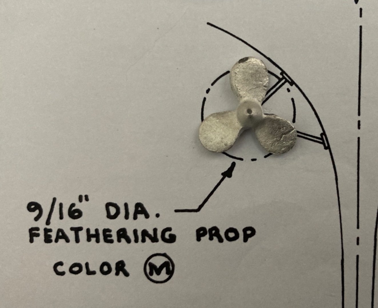
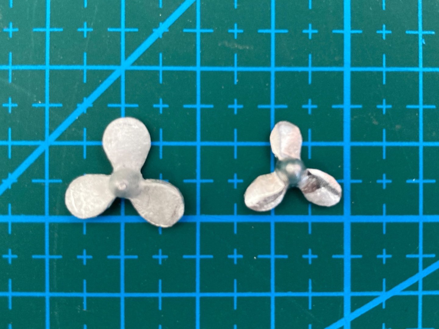
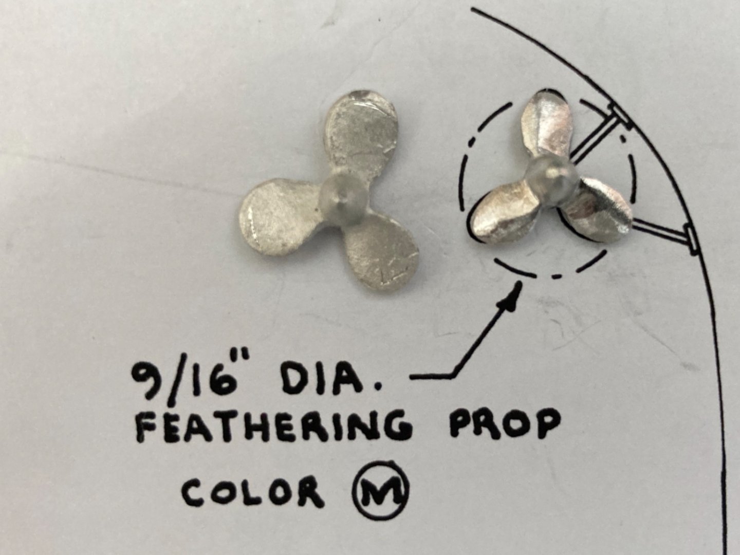
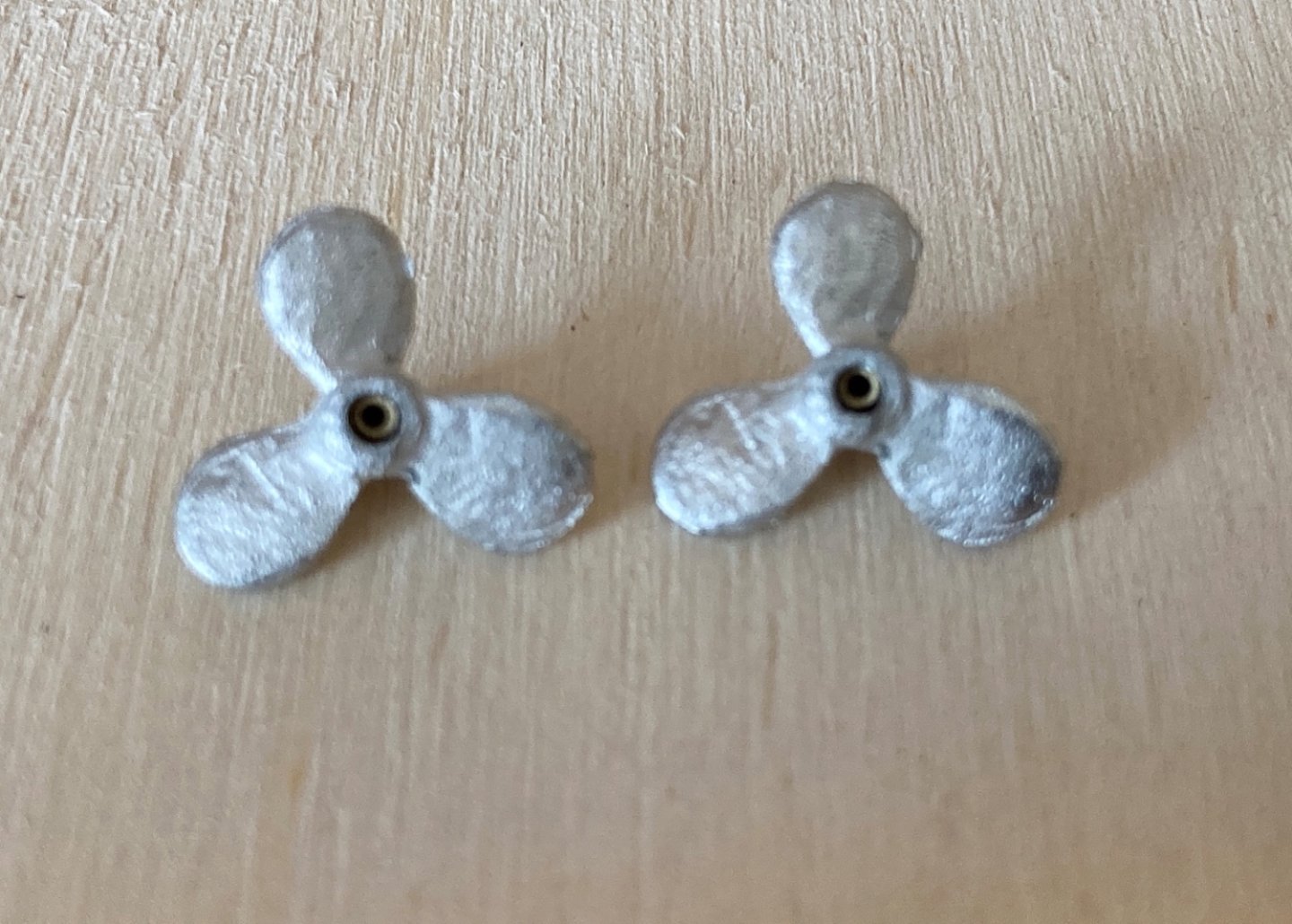
It is now the 9th month of real-build-time of the model.May 2021. Before beginning the paint job on the hull, there were a couple of steps to be finished. One of them was the preparation and installation of the propeller and its related structures like shaft, shaft log and support struts. Of all the models in the forum and in the others found on internet, only one modeler (Jdbondy in MSW Forum) added the propeller system to his model. The reason and argument of the modelers who have not added the prop system to their model, was that they were planning to build the model of the original ships build in early 1800 s which inspired the Baltimore City Council to build a replica. That is understandable if you exclude the engine room hatch from the deck and the POBII lettering from the bow and upper transom. However in many of the models build without propeller system , both engine room hatch and POBII lettering was included making those models somewhat with missing a major part. Imagine a model with an engine room below the deck and missing propeller system ! I decided to follow the plans of with the present ship and began to build the propeller system. The system consists of 4 parts. Propeller, propeller shaft, shaft log and shaft supporting struts. The color of the propeller (Brass) and the propeller shaft (Steel) are the same in the real ship . In the plans shaft log and the struts are shown in Bronze color. However in the below photos of the ship provided by the crew those are the same color as the hull, dark green. I decided to use dark green. The kit instructions dictate to solder the metal pieces when preparing the struts and shaft logs. I had no previous experience with soldering and as the pieces to be soldered were tiny, I decided to use epoxy glue . I was successful with the shaft logs. However although the struts were erected , they felt somewhat weak and probably will dismantle easily when I attempted to attach them to the hull. So I decided to cheat a little here and made the struts from one piece of brass sheet and add a piece of brass tubing later. I drilled 0.5 mm (3/64 inch approx) holes on the strut leg pads for nails. Dry fitting of the system. By taking measurements from certain points on the hull like already installed pintle and gudgeon brackets on sternpost, gunport #5 and corner of keel and sternpost , I marked the places where shaft logs and strut pads to be glued. The corresponding holes on the deck were drilled. Here are some photos of the dry fitted propeller system on the hull. Here there was another example of the out of scale metal parts of the kit. The propellers were larger than the plan. So they have to be reduced in size. The reduced size now fits to scale Here is the dry fitting photo after propeller size reduction. Also the diameter of the holes on the propellers in which the propeller shafts will go, were larger then the shaft's. Small pieces of brass tubing were placed in those holes in order to provide a more stable system when the shaft are inserted. Shaft logs were glued in place. I planned to install the struts after applying the primer paint coat.


- 114 replies
-
- 3
-
-
- Pride of Baltimore II
- Model Shipways
- (and 1 more)
-
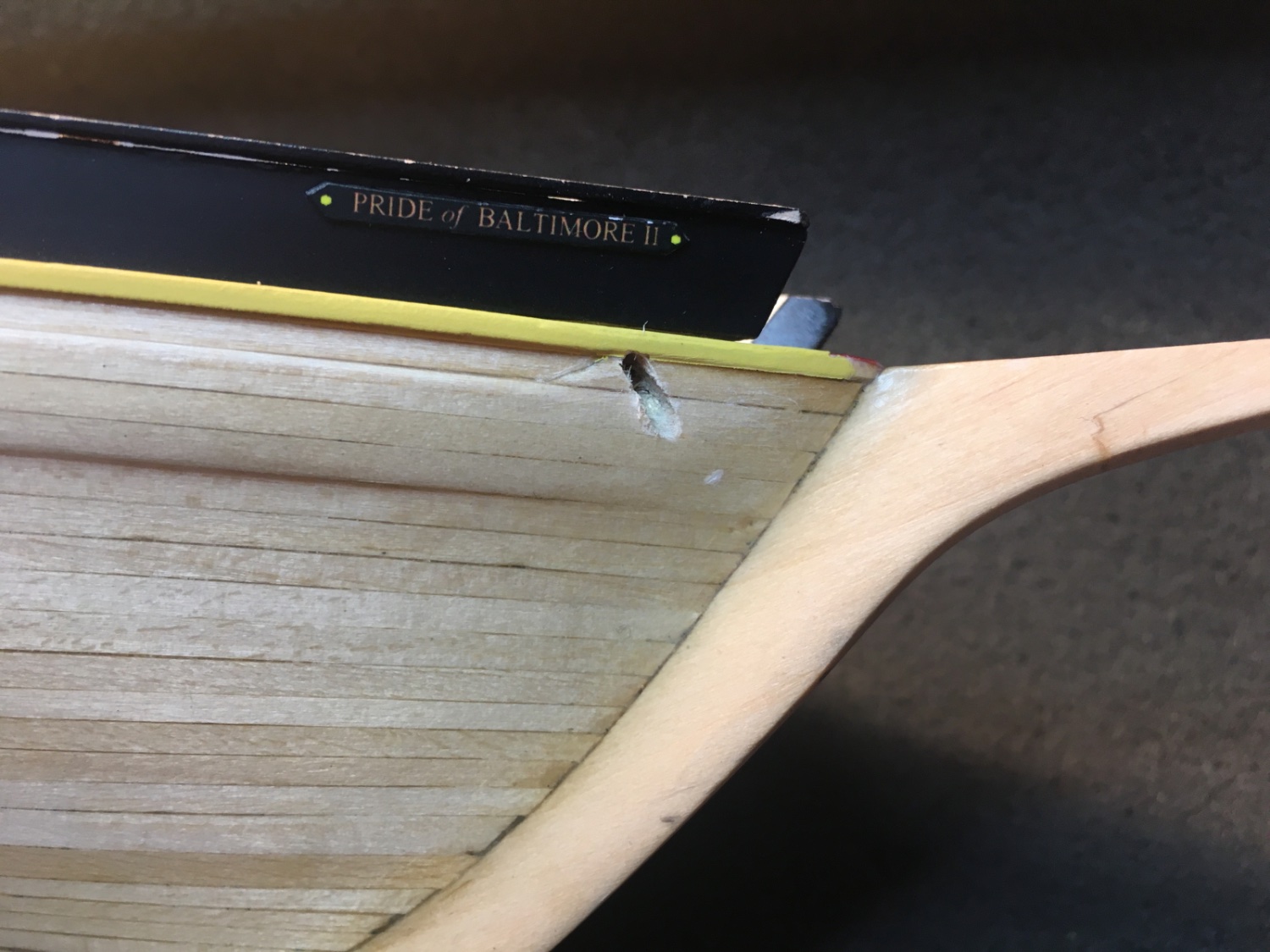
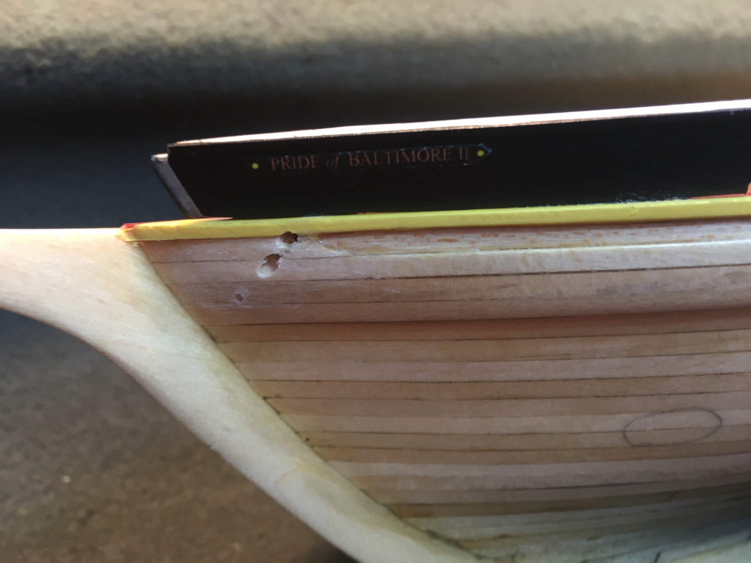
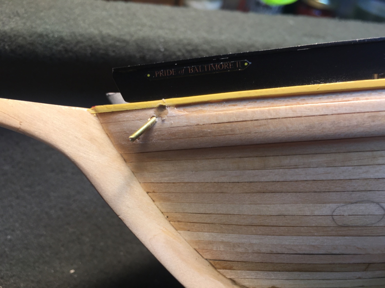
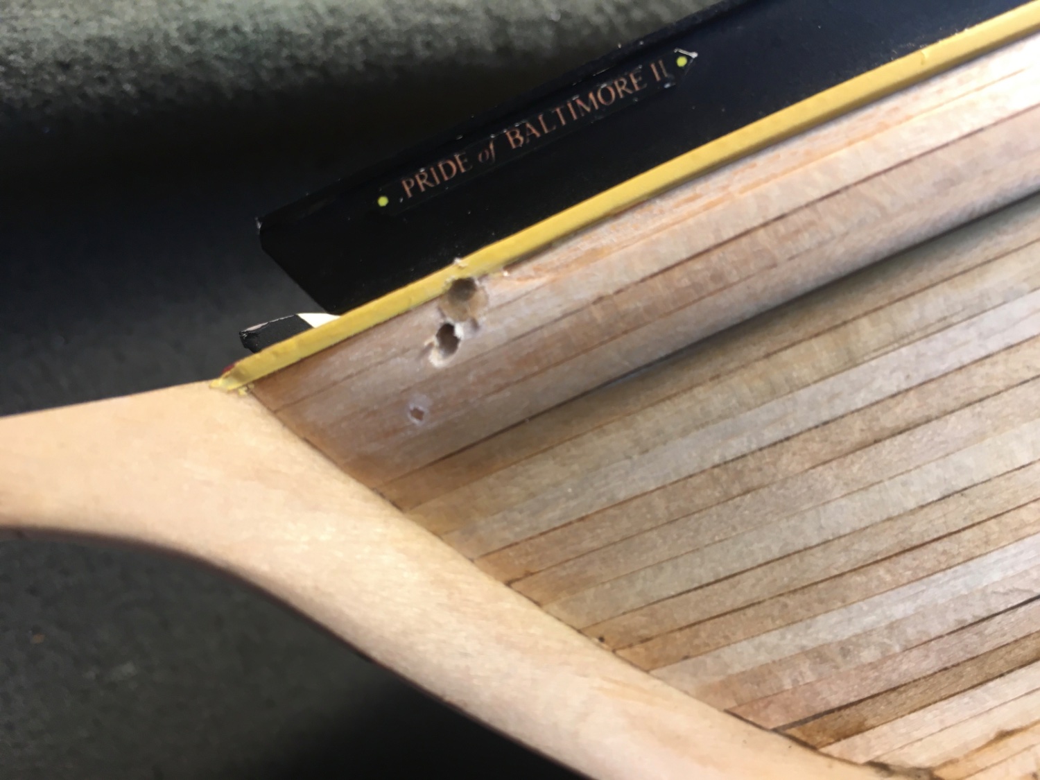
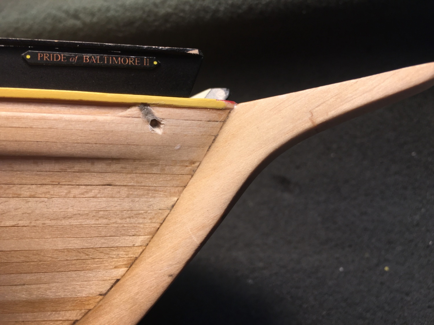
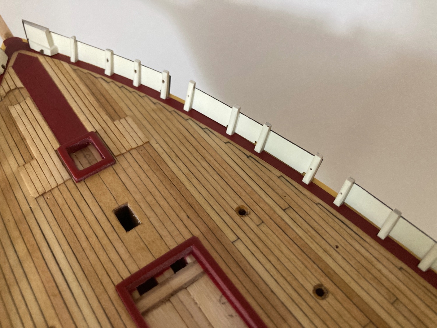
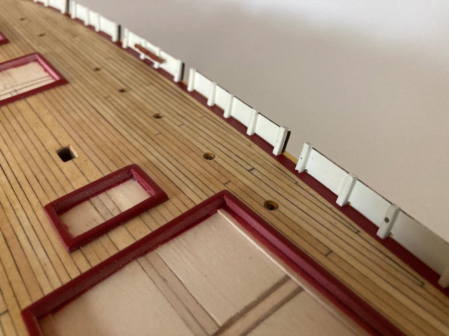
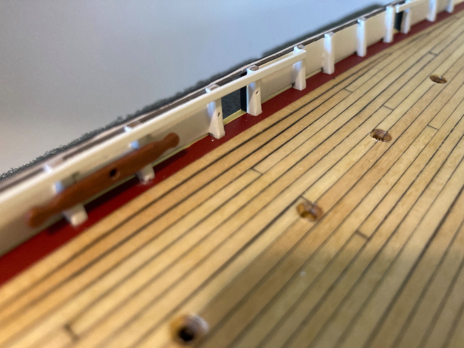
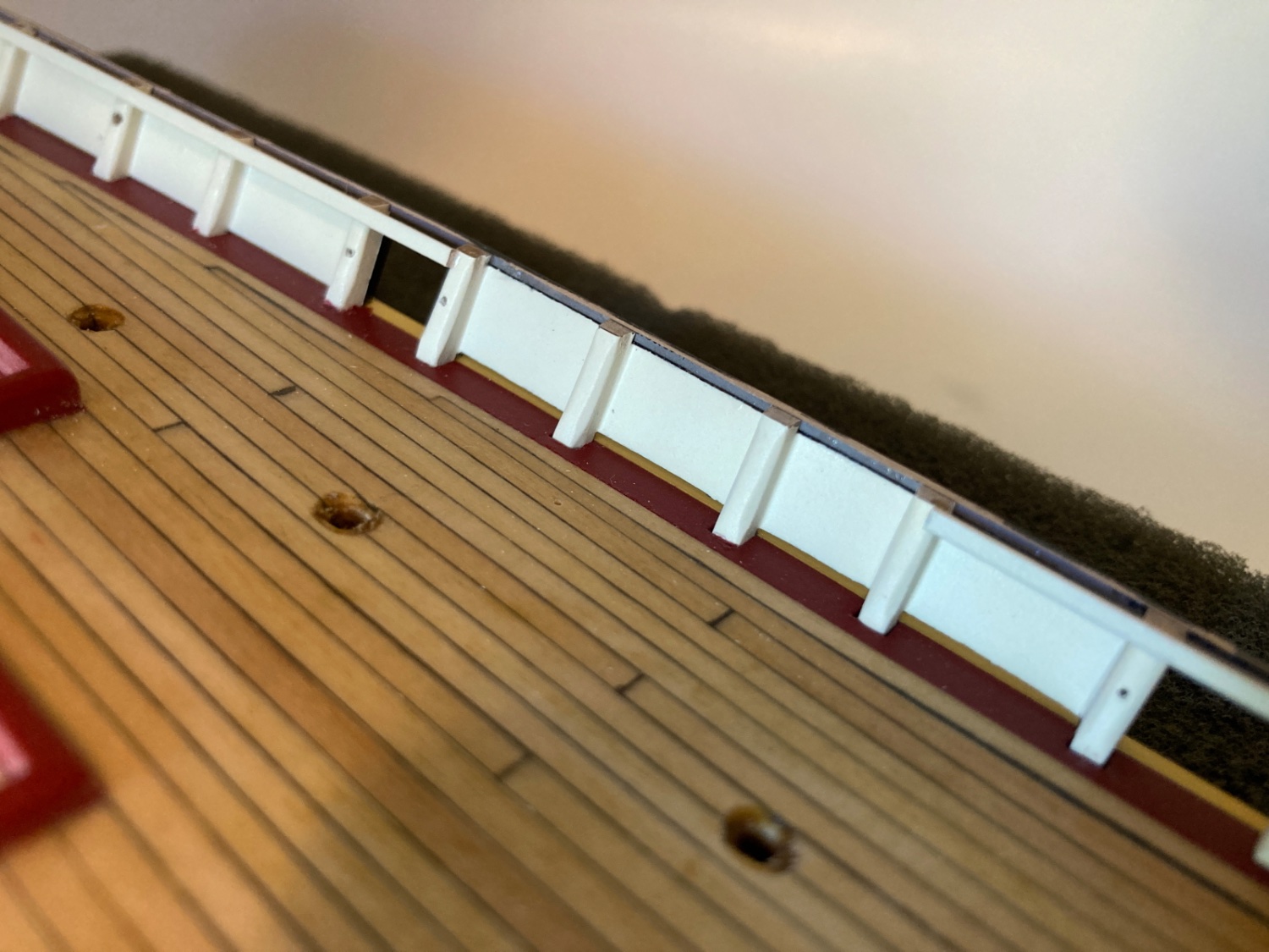
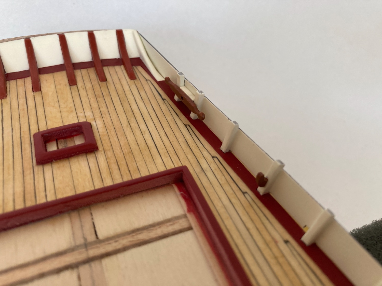
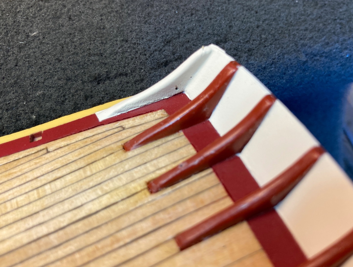
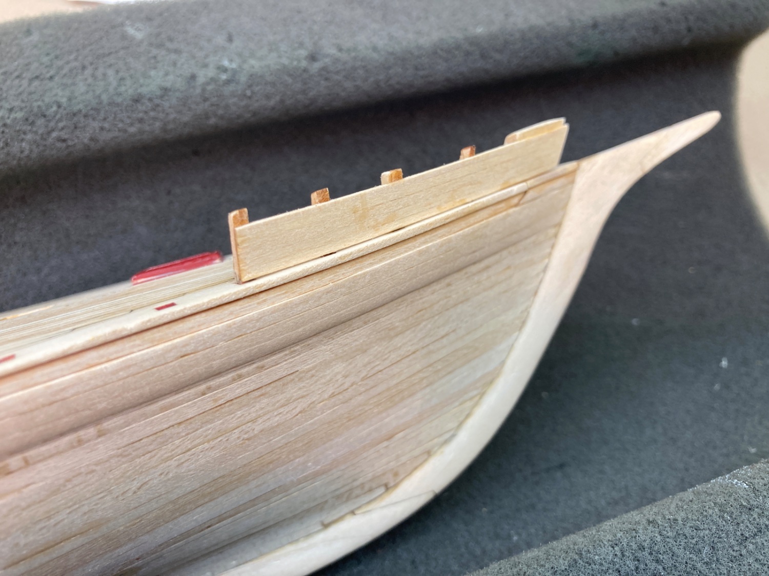
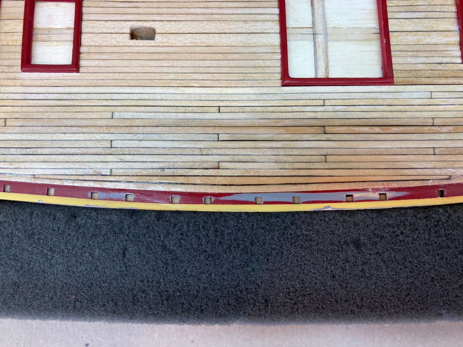
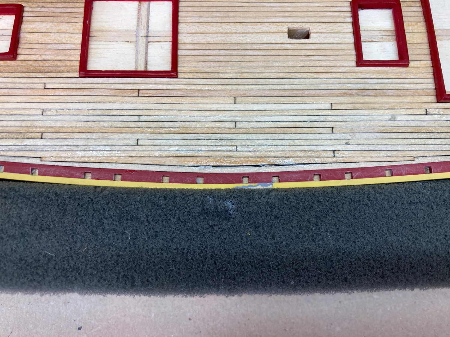
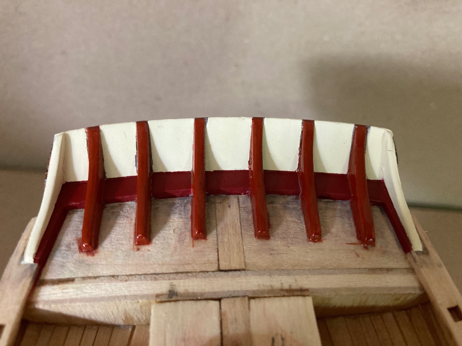
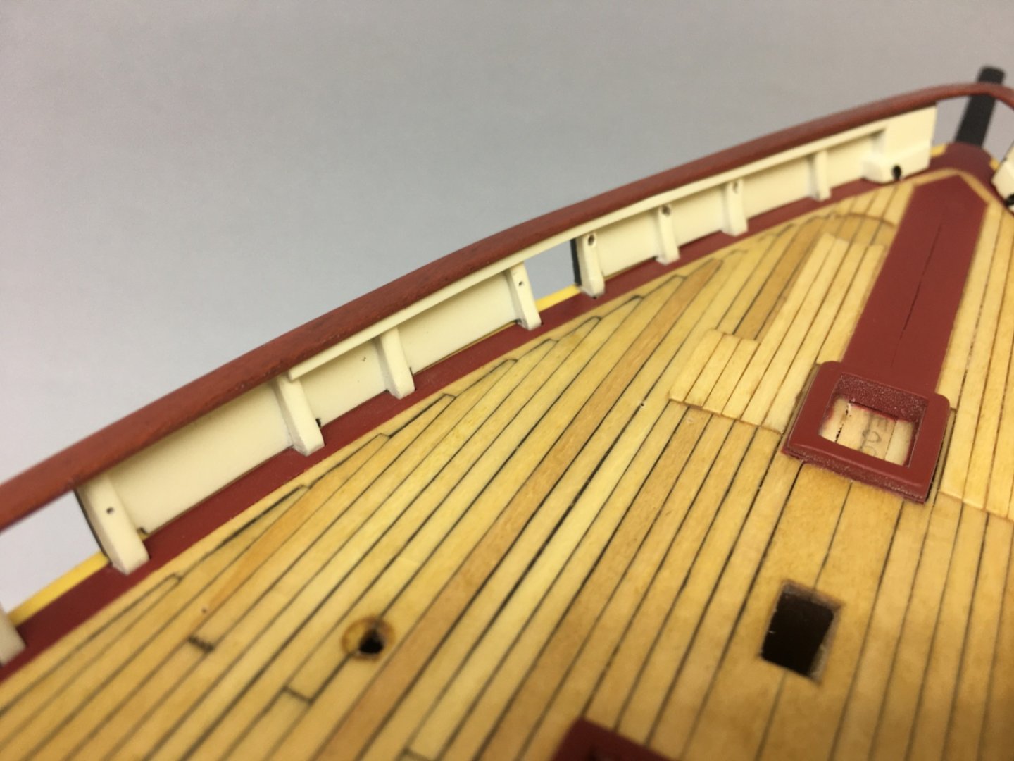
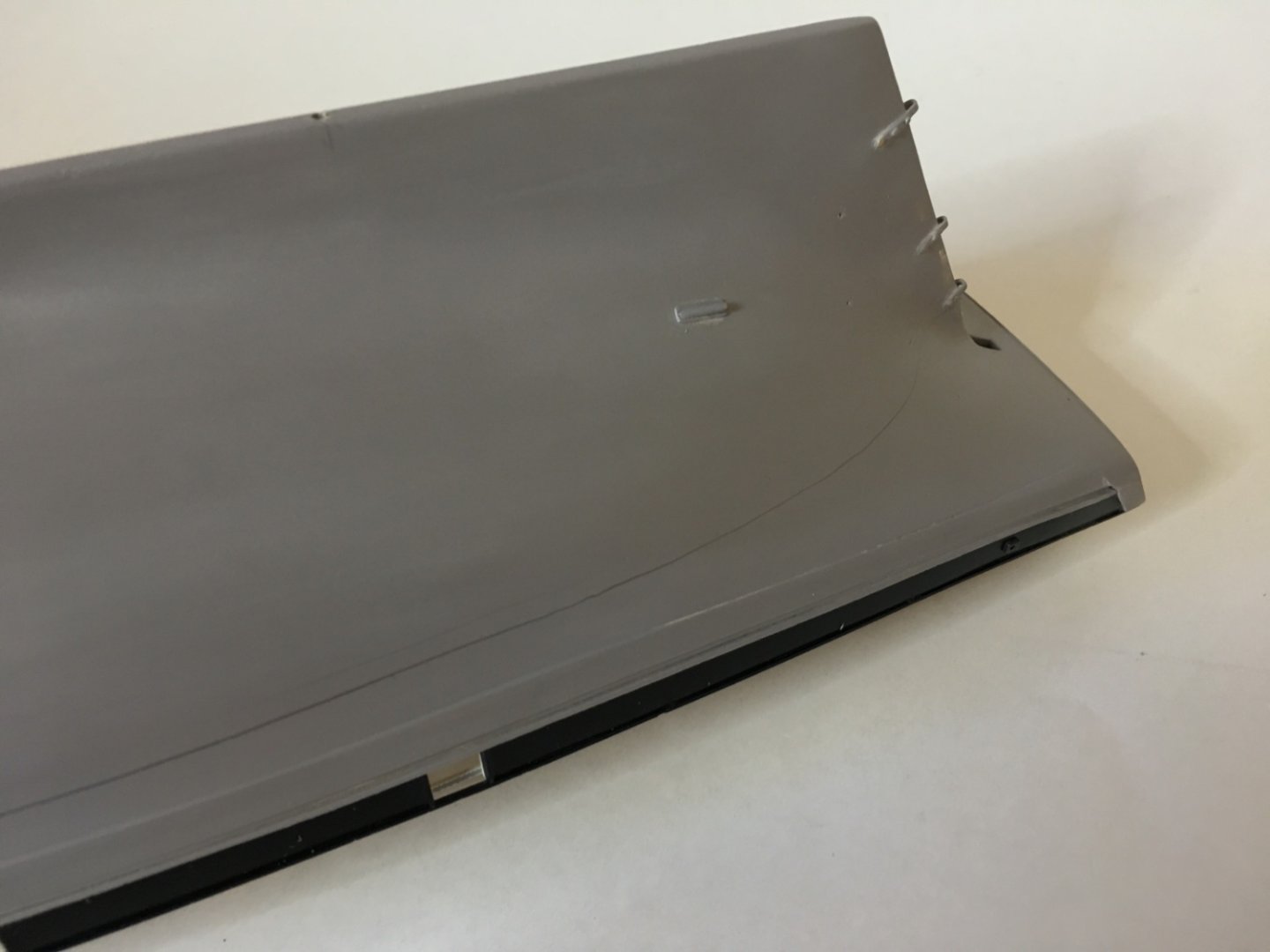
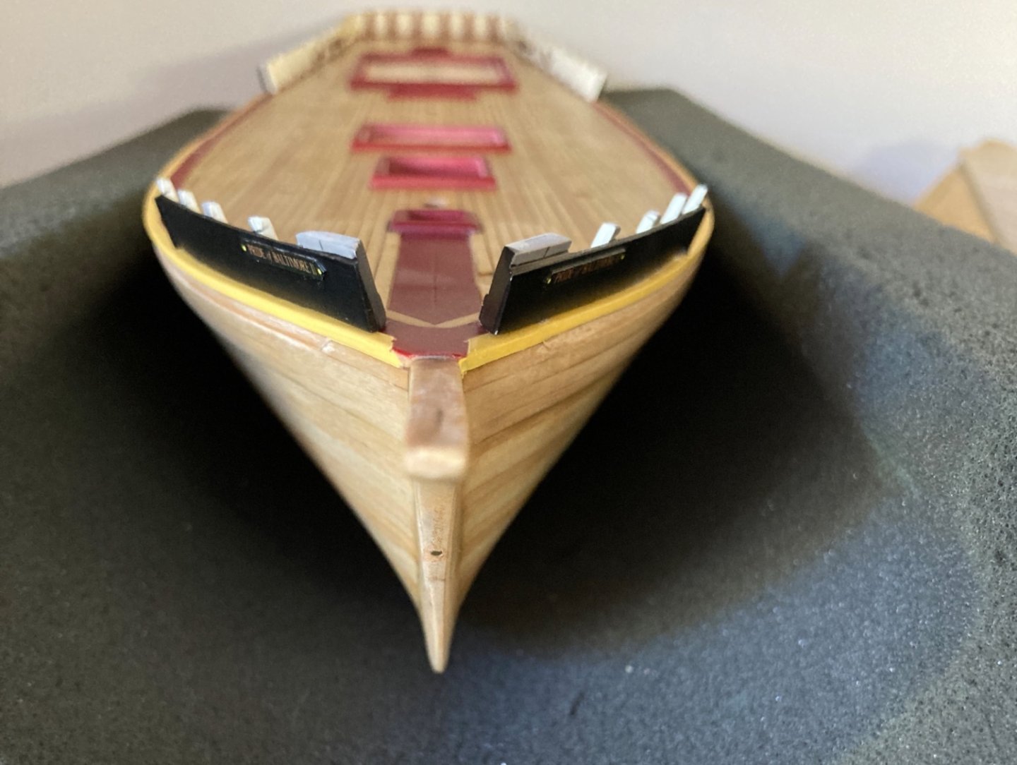
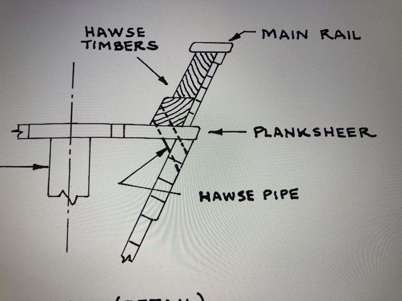
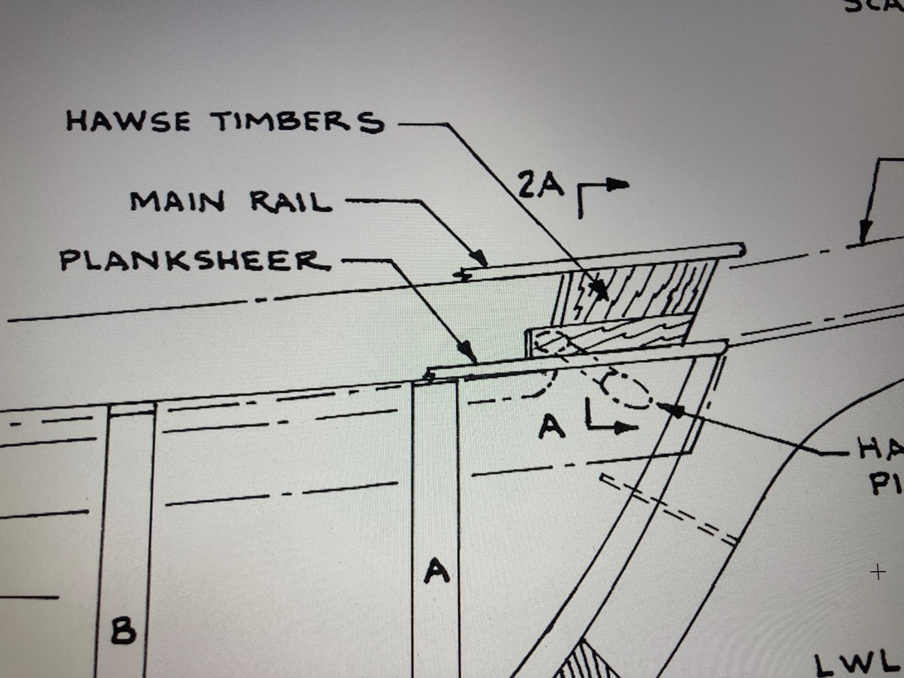
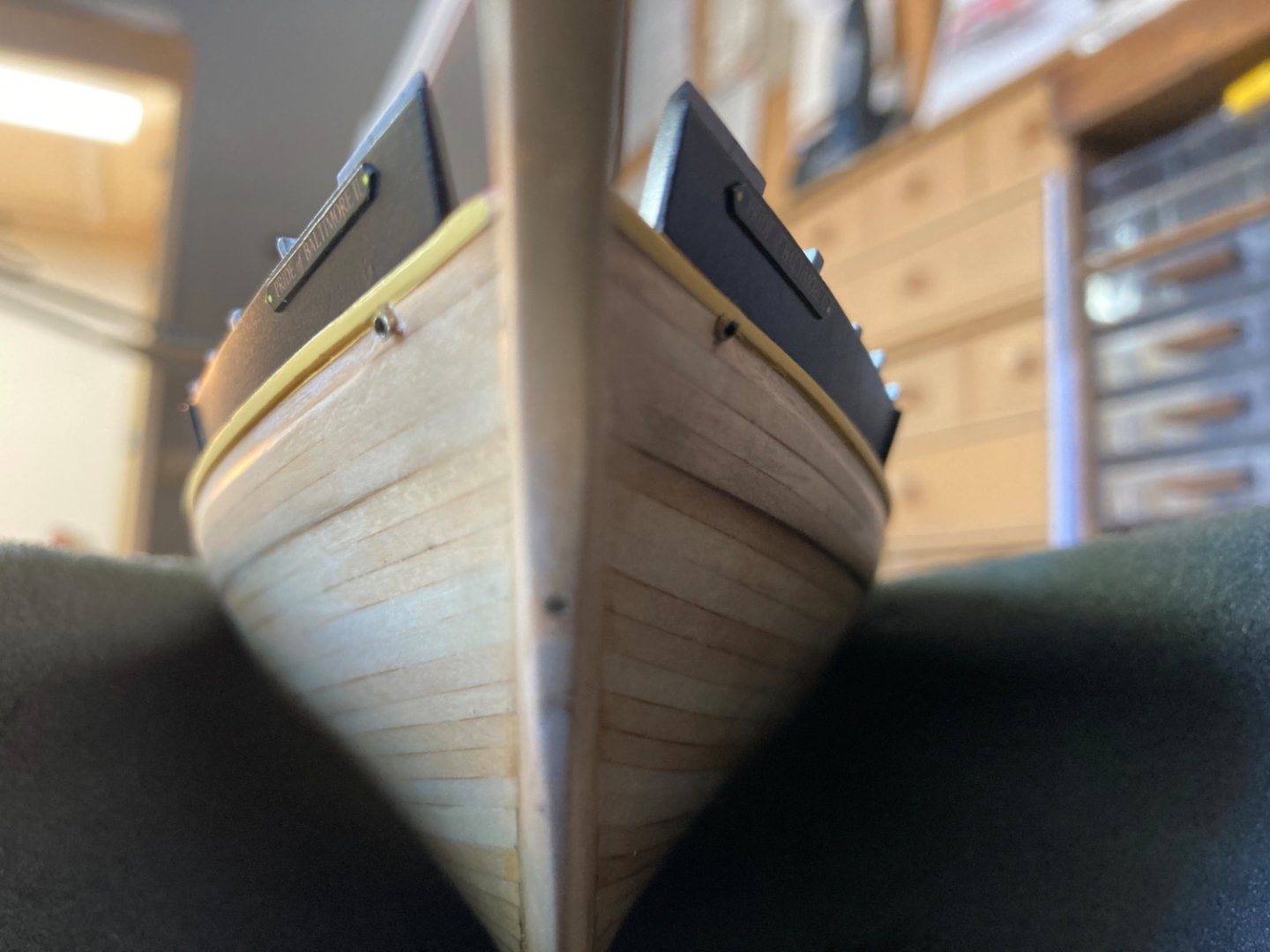
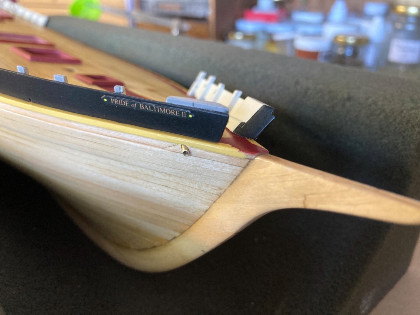
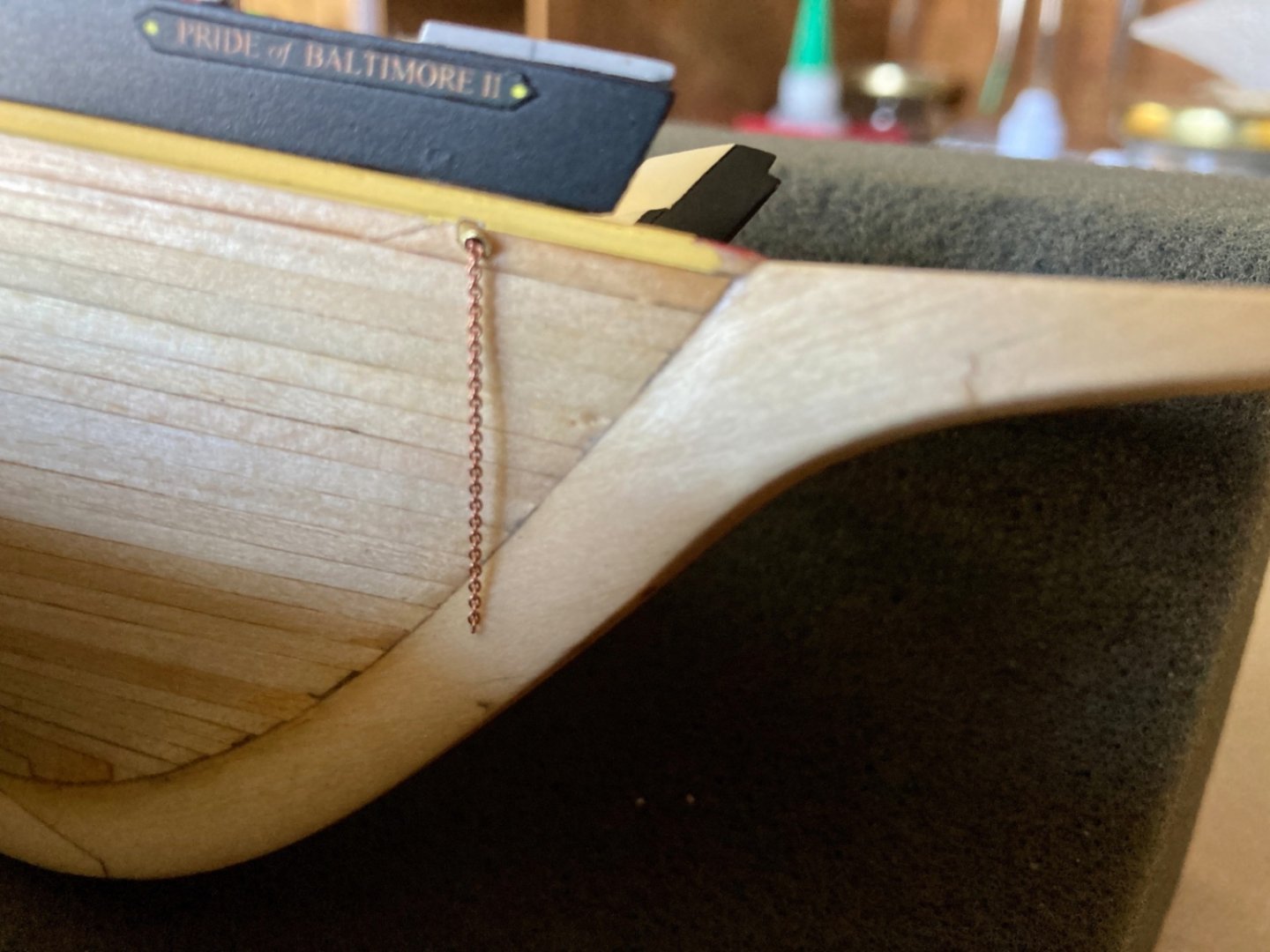
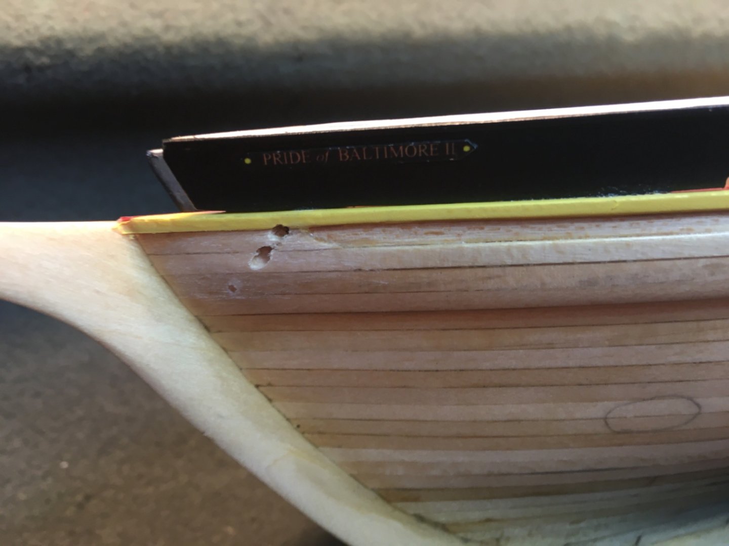
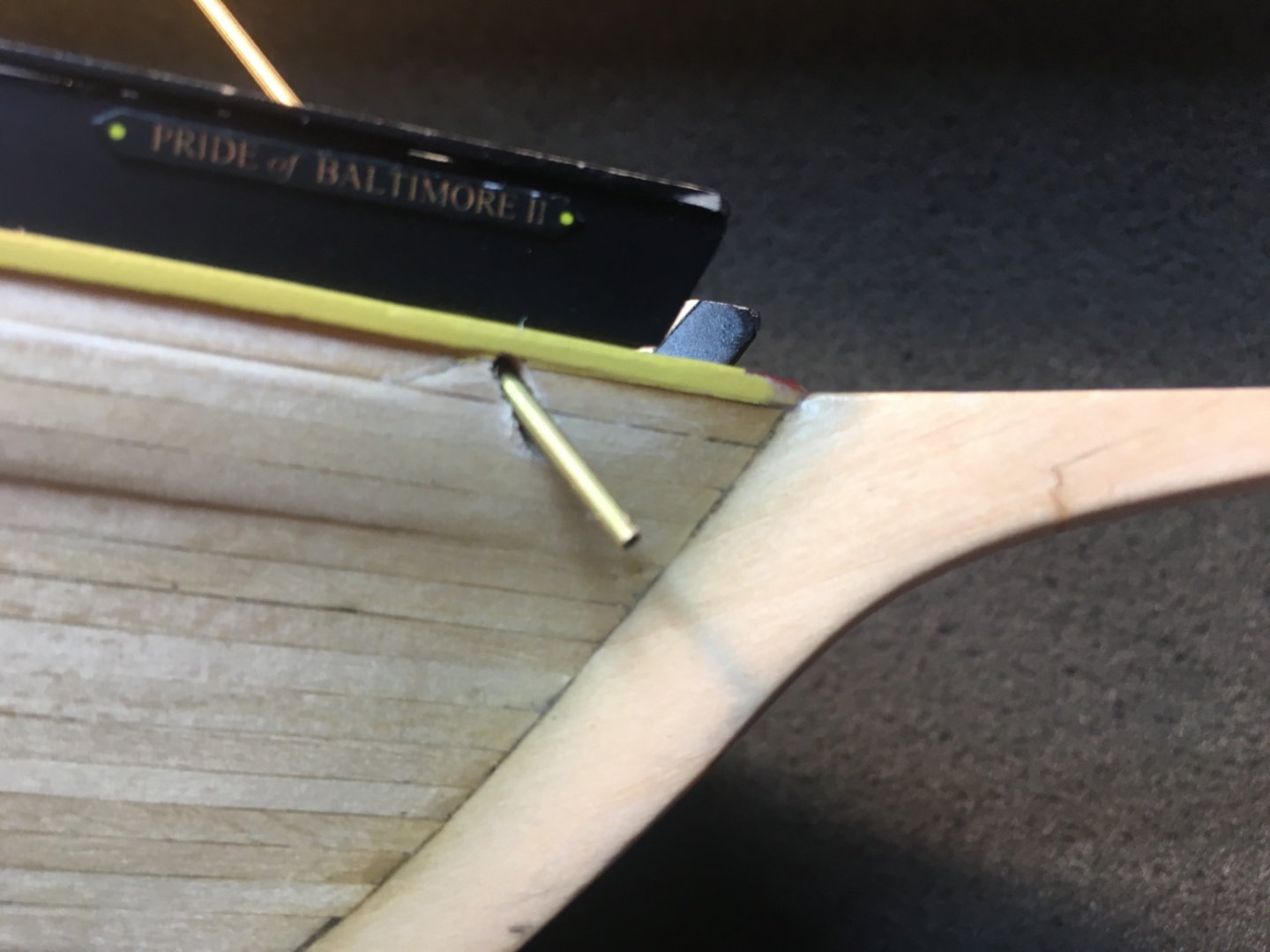
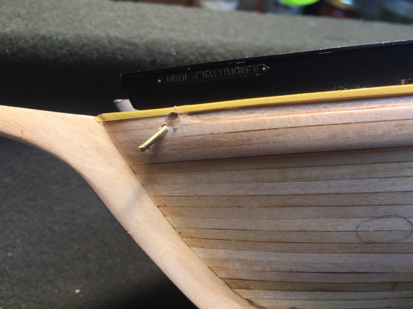
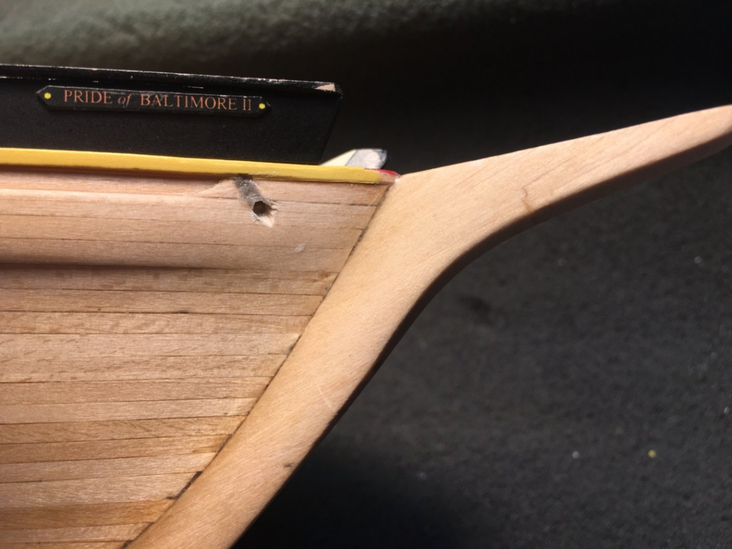
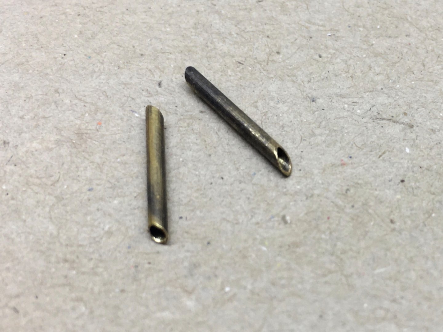
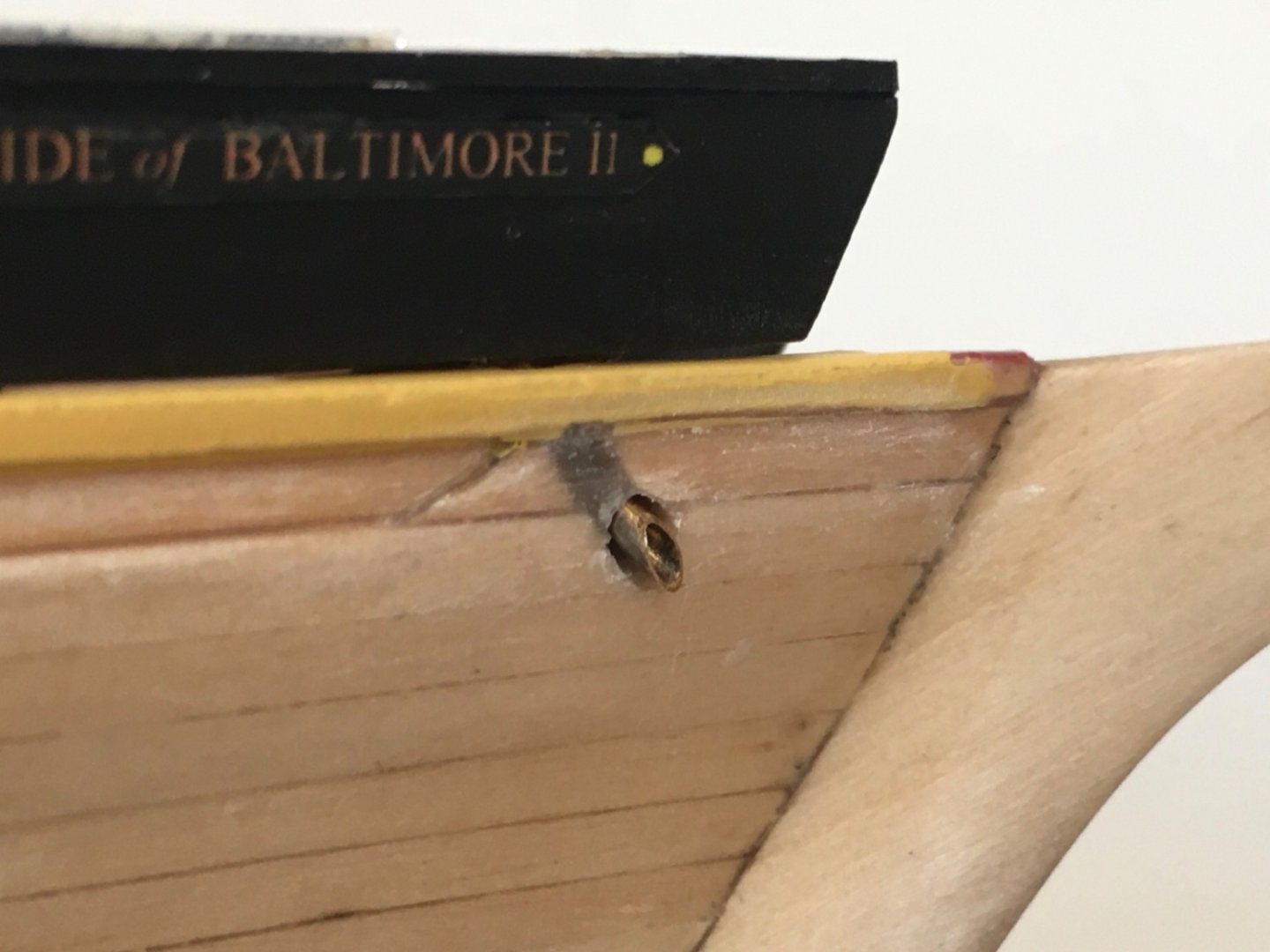
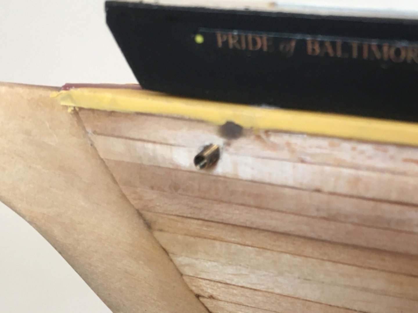
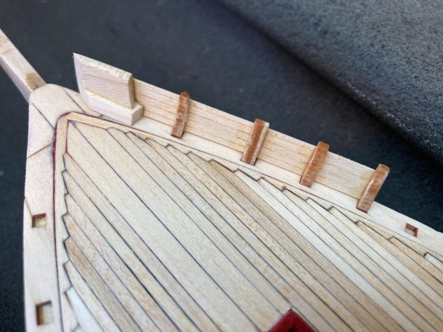
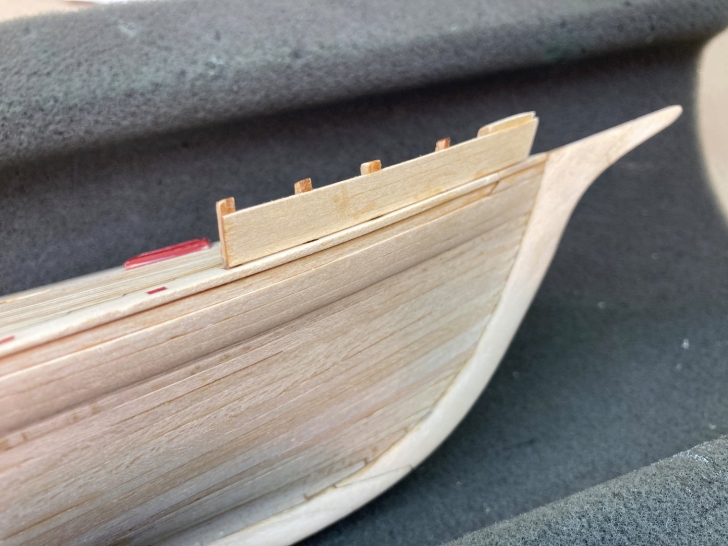
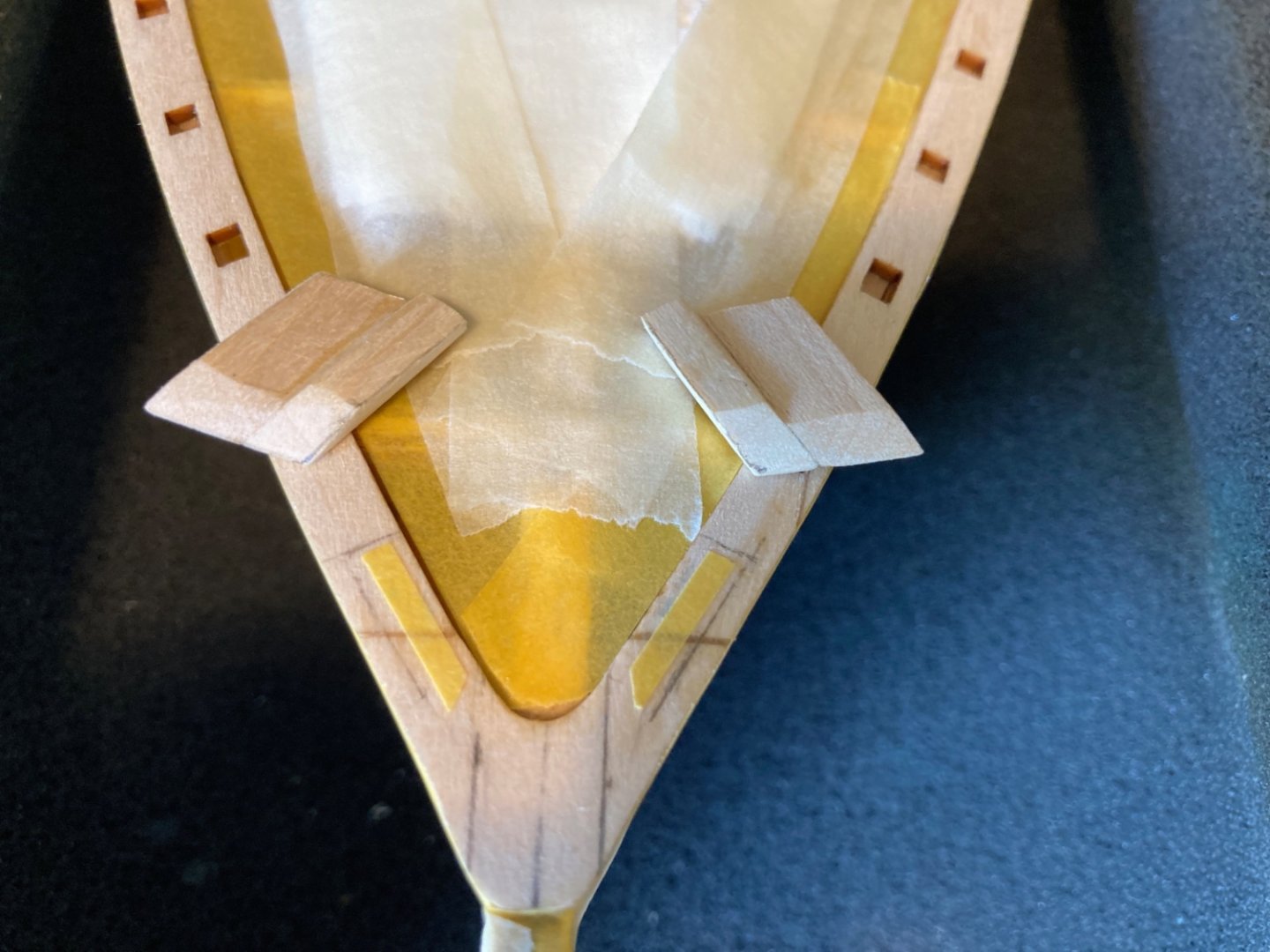
After making peace with the model and hoping to keep the faulty bulwark issue as a secret between us, I moved on with the installation of the bulwarks starting from bow end. The very fore end of the first section of bulwarks is the hawse timber blocks. In order to have sturdy result when gluing this section, I made two corresponding holes on the plank sheer and the bottom of the hawse timber block and placed a nail in the holes as seen in the , unfortunately out off focus, photo. Then the first bulwark sections on both sides were installed. Before continuing with the rest of the bulwarks, I decided to deal with another daunting step which was drilling out the Hawse Pipe holes in the bottom piece of Hawse timbers. The procedure here is a bit tricky and you have to think in three different angles and make a drilling direction plan. From inside to out , from back to front and from above to below. In short words it was HARD. The holes diameter must be 1/16 inch (1.6 mm). I first used 1/32 inch (0.8 mm) diameter drill bit , followed by a 3/64 inch (1.2 mm) one and finally 1/16 inch (1.6 mm). The result was not perfect as expected and the outboard holes were 1-2 mm higher than the designated ones but they were at least symetrical . Checking the anchor chain (on the wrong side !) At that time I continued with the installation of the other bulwarks section which was uneventful. However in some later stage of the build and before the hull painting job, I decided to re-drill the holes. Here I will fast forward the timeline and show you how I did it. This time I started to drill from outboard to inboard direction and started the drilling from the oytboard hole’s exact location. During the procedure the new channel connected with the old one and drill bit tip came out from the original inboard hole. The procedure was perfect on port side but on starboard side the new hole and the old hole were connected which needed a repair. Two 1/32 inch (1.6 mm) brass rods were placed in the new opened channels and the remaining spaces were filled with basswood sanding dust. Gap filling CA was applied with glue applicator on them. Sanding sealer 1:1 concentration with lacquer thinner applied to smoothen the surface. This time the result was more acceptable. Starboard side Port side Brass rod in holes After sanding dust and CA glue application. As the length of the channels were increased new brass tubes were cut with angled ends. OK ! Now back to present build time. As I said before the installation of the remaining bulwarks was uneventful. The next step was the installation of the outboard and inboard bulwark stringers. You have to start with the outboard stringers because they will mark the height of the bulwarks. Here placing their 1/32 inch (0.8 mm ) edges on stachions must not be forgotten. Now as the height of the bulwarks are set by outboard stringers, it is time to sand off the remaining bare tips of the stachions. This was done carefully by holding the bulwark section to be sanded with left hand , wearing a powderless glove of course, and doing the sanding job with the right hand (or vice versa) . Now the inboard stringers, painted light cream, can be placed . This time leaving spaces for pin rails as well as placing 3/64 inch (1.2 mm) edges on stachions must not be forgotten.


- 114 replies
-
- 4
-
-
- Pride of Baltimore II
- Model Shipways
- (and 1 more)
-
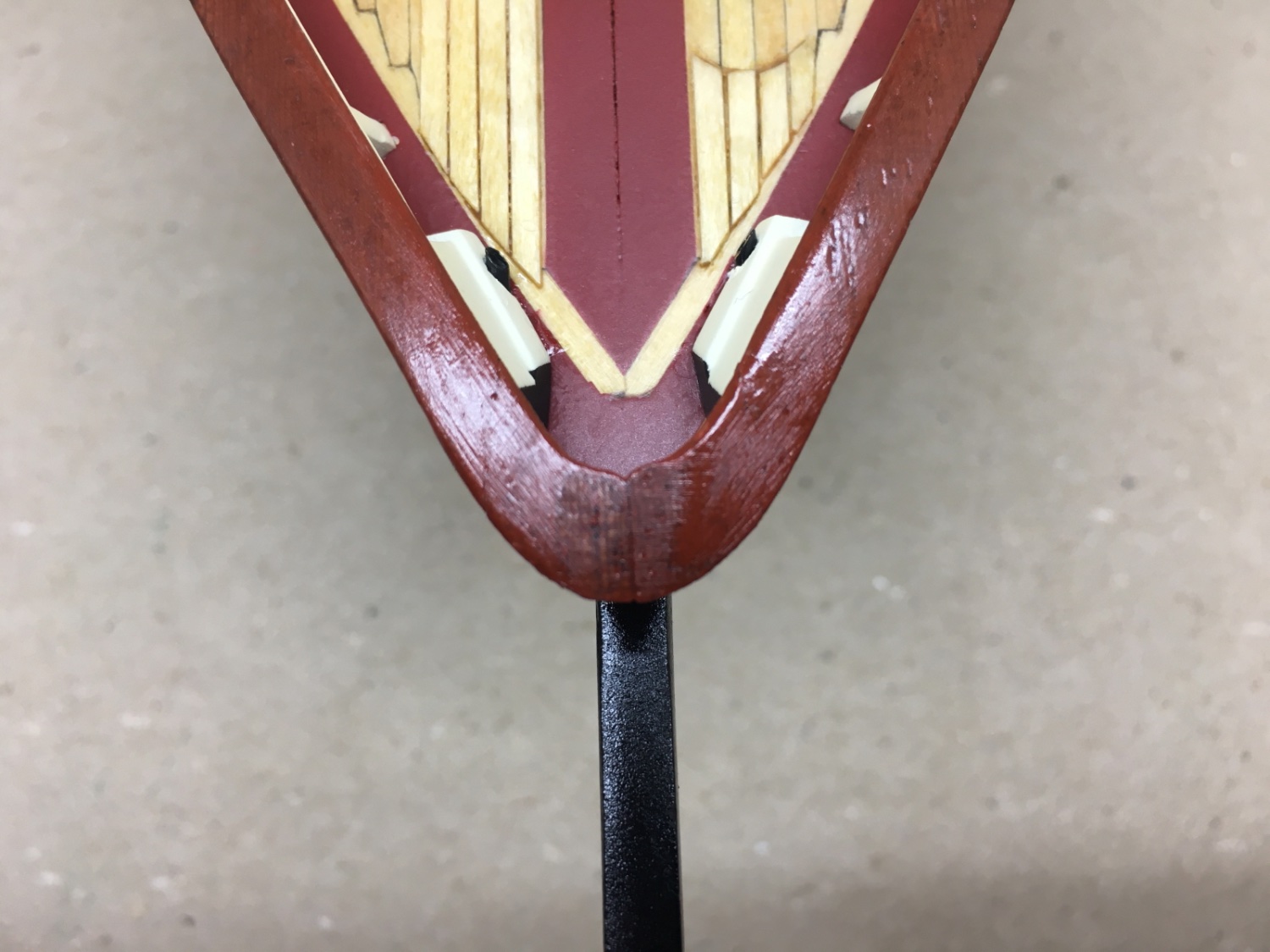
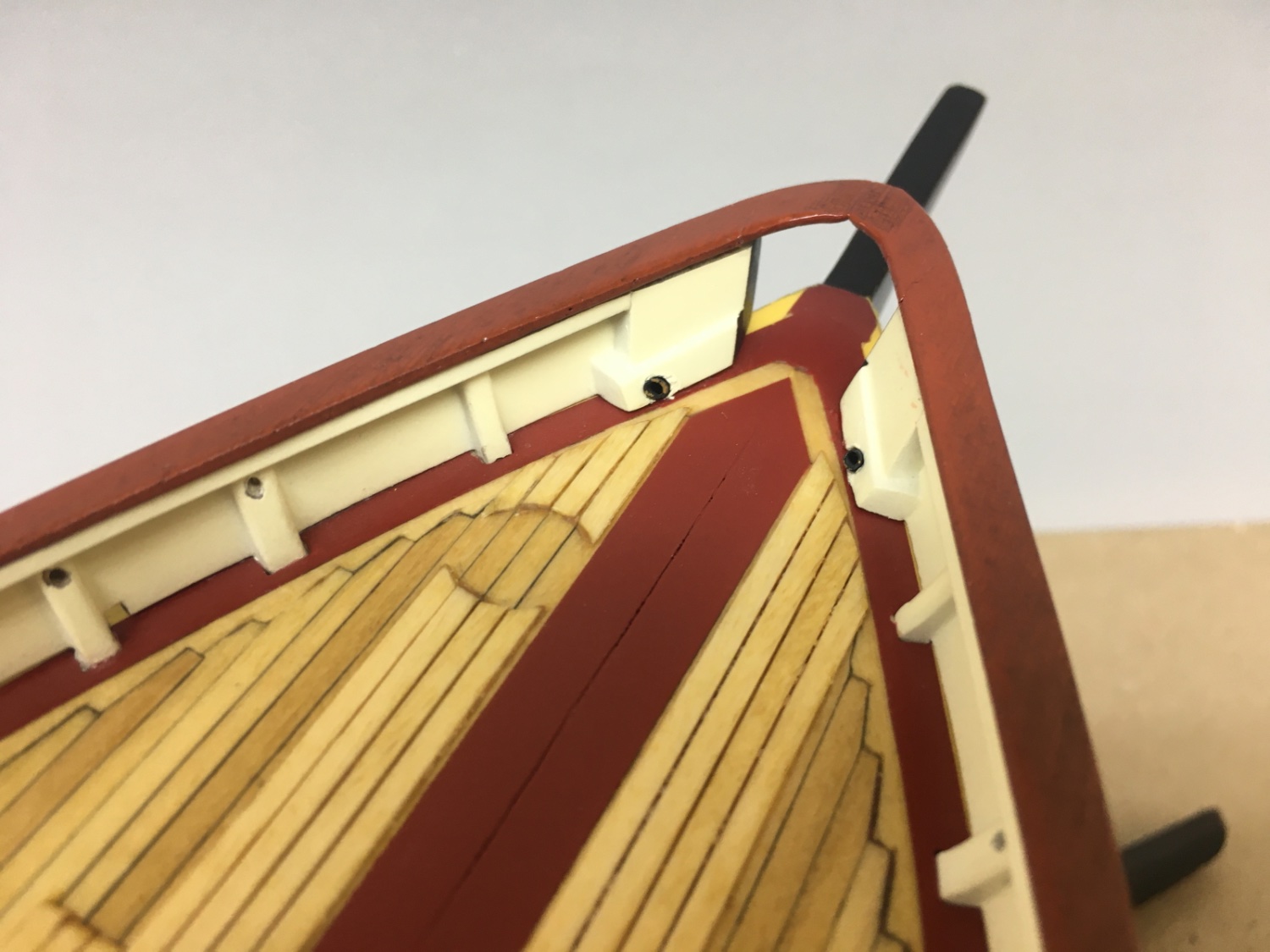
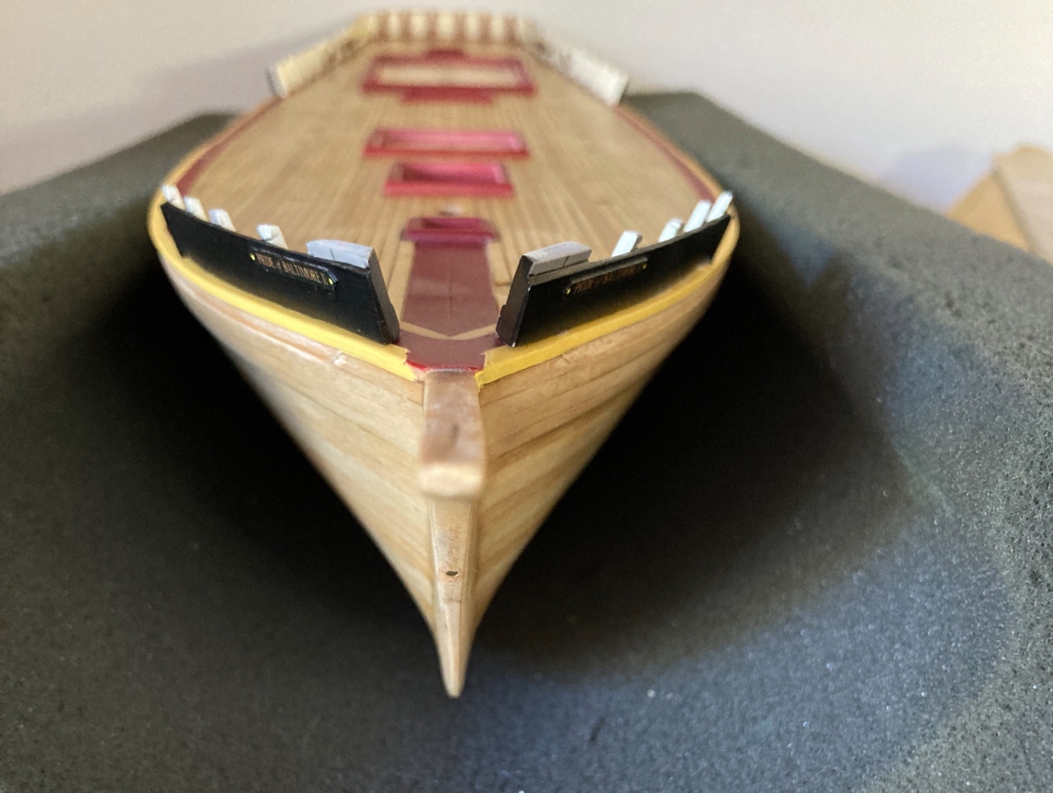
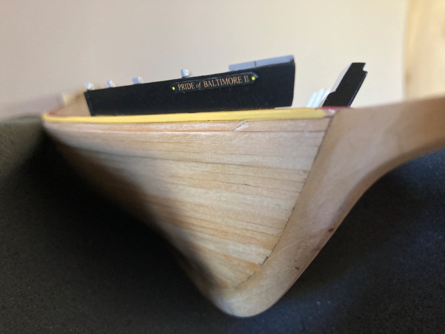
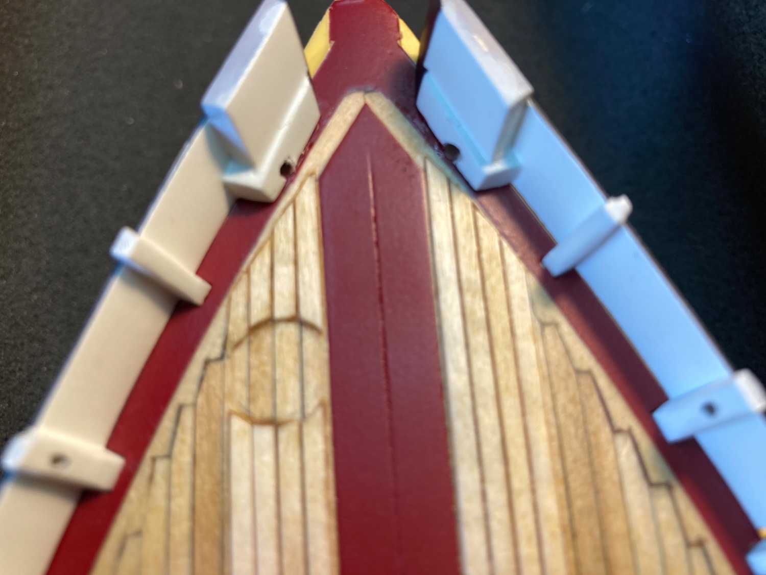
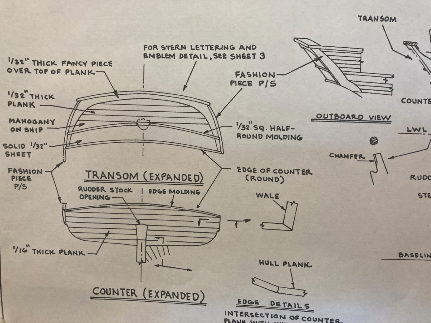
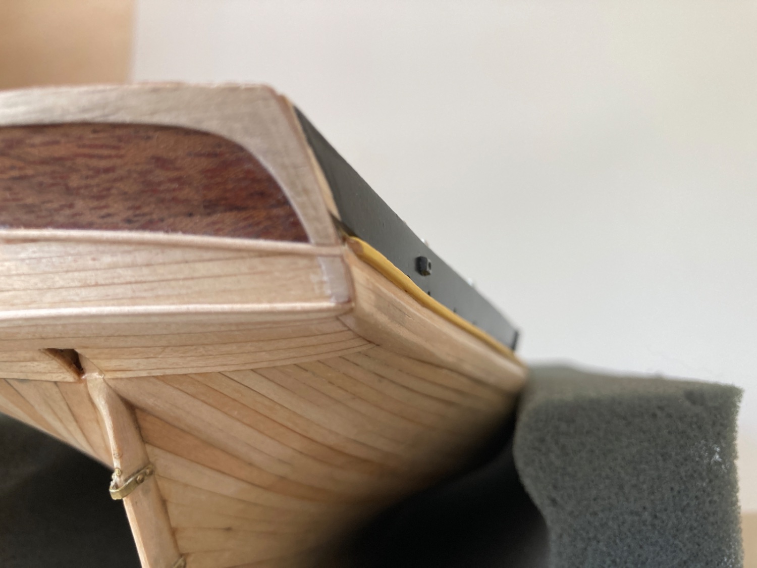
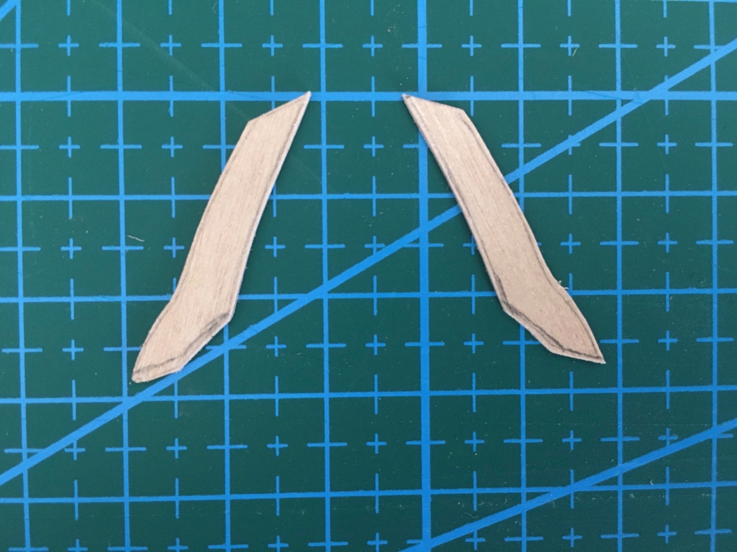
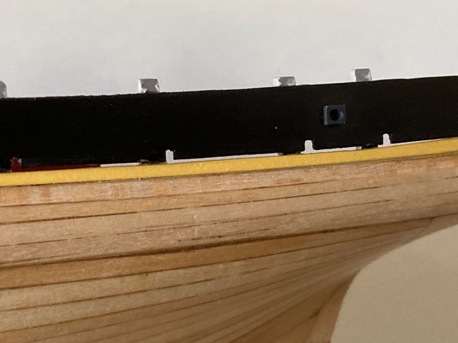
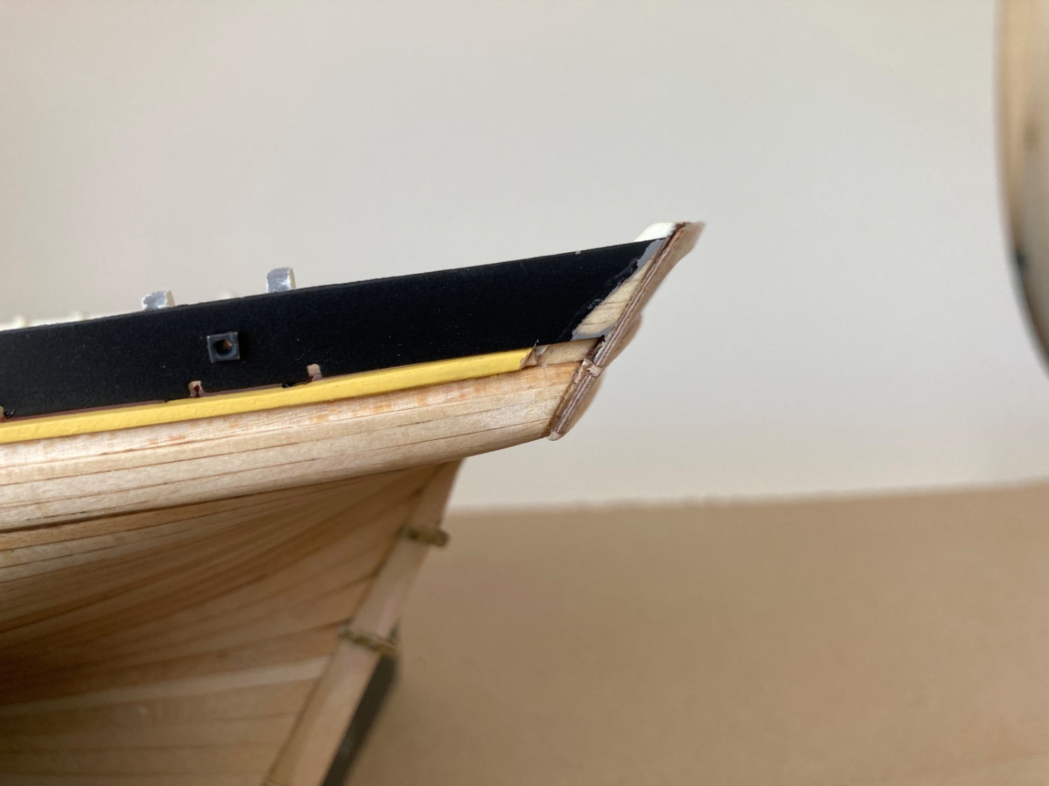
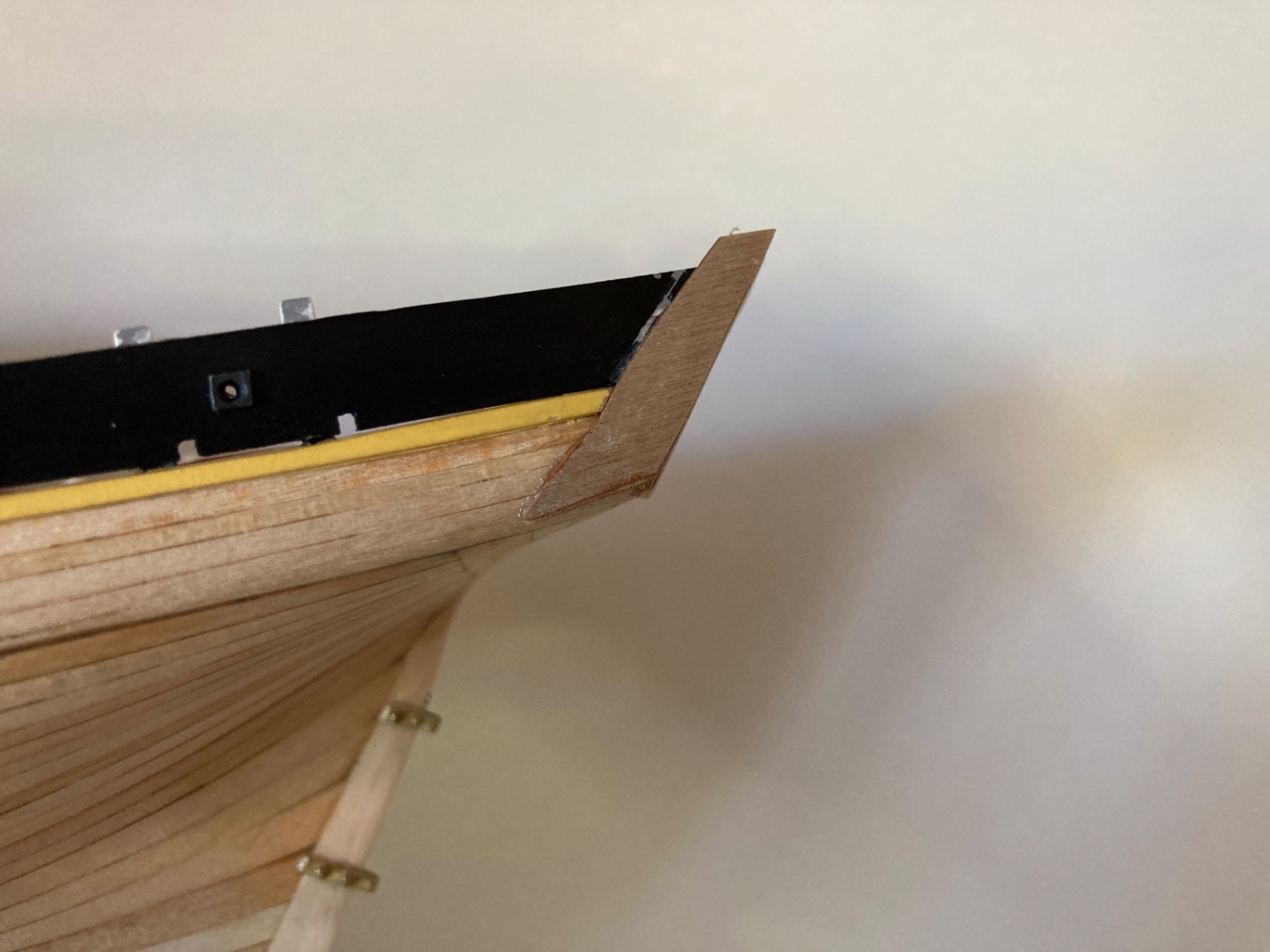
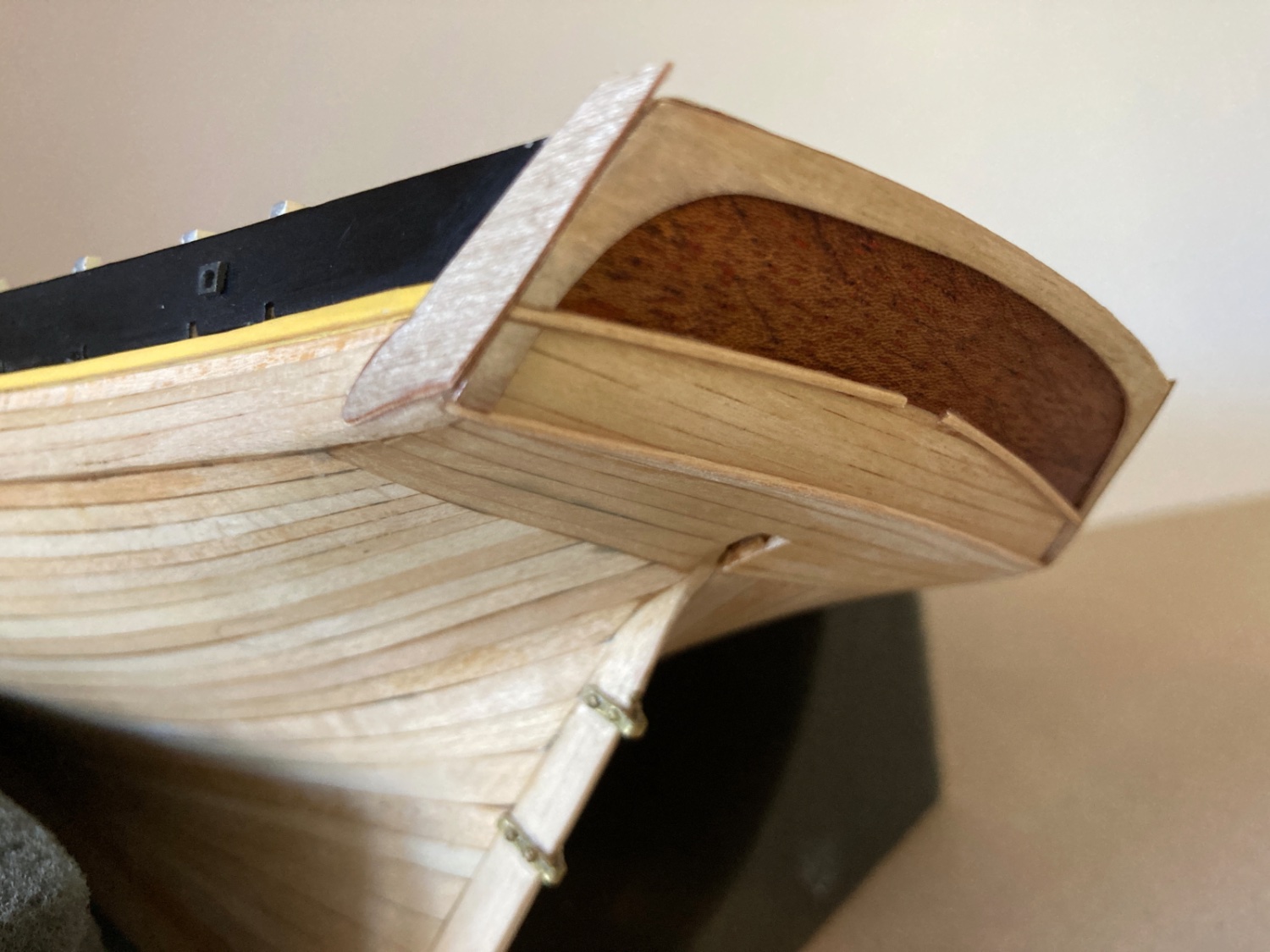
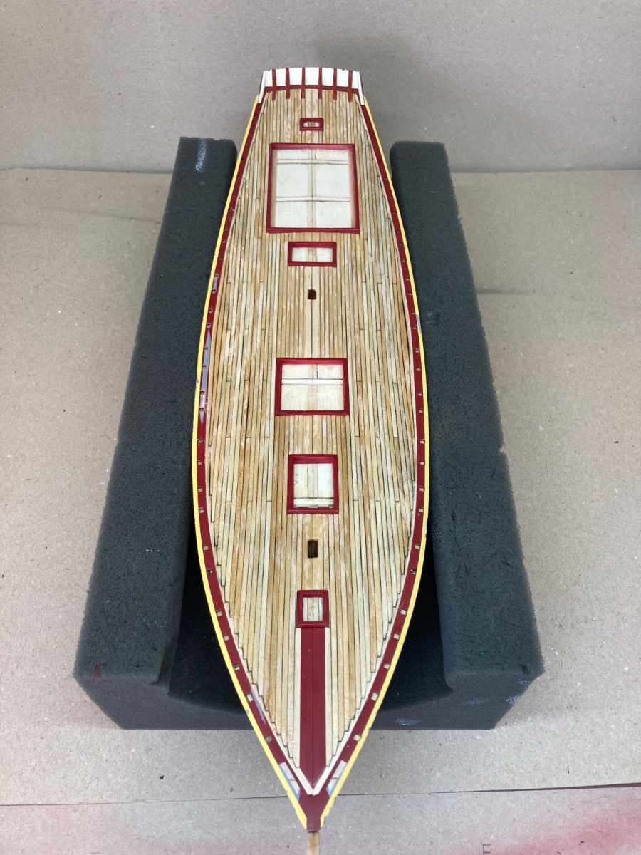
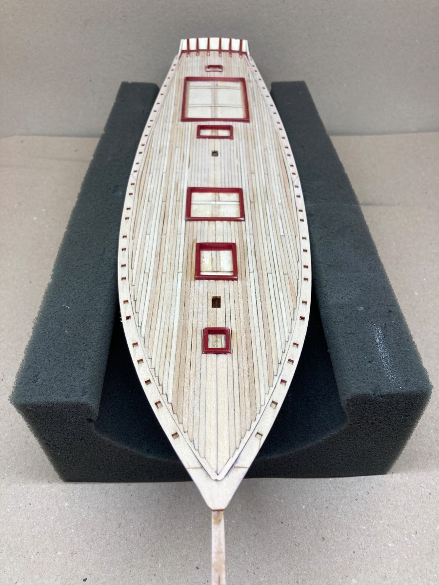
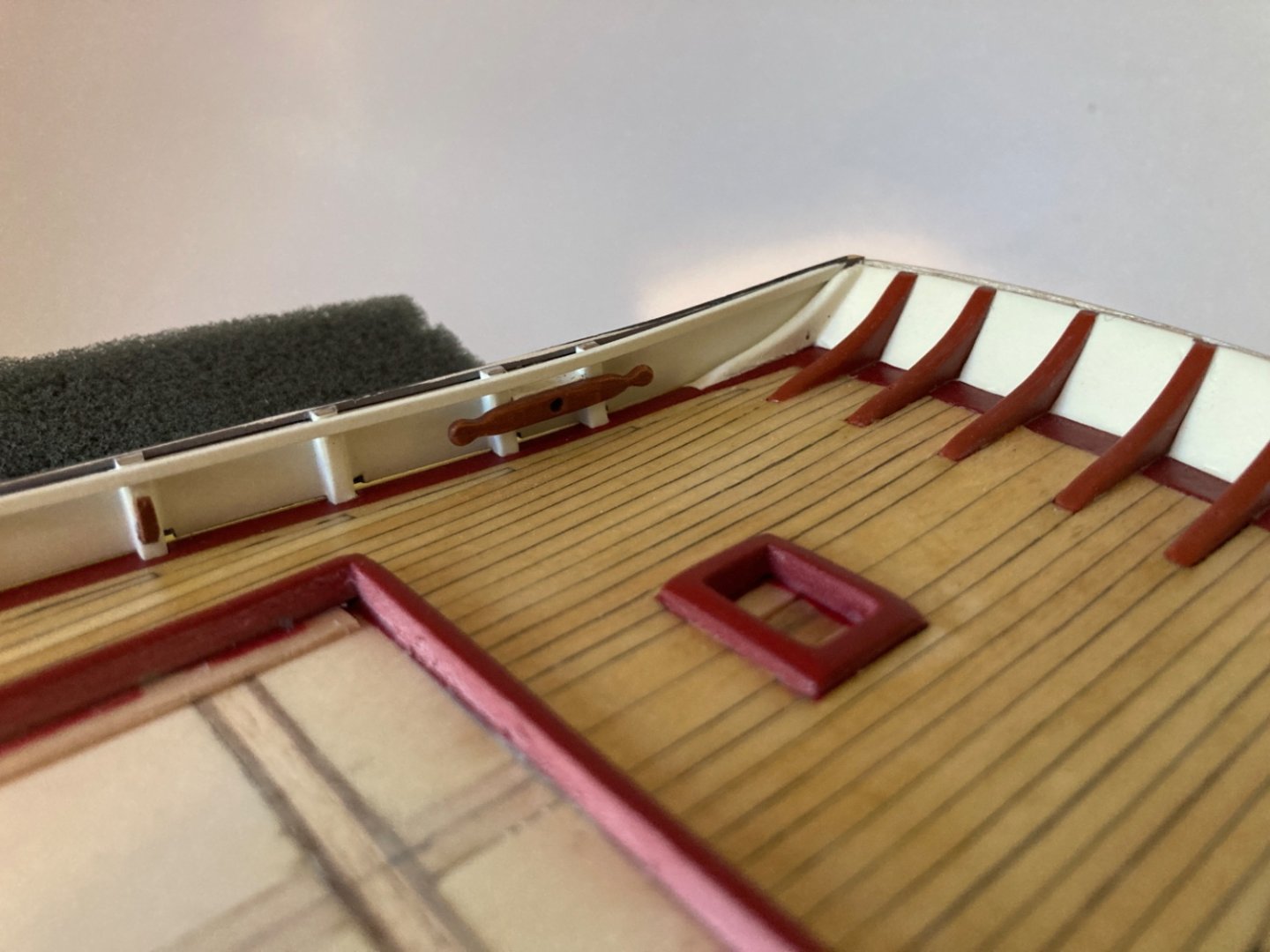
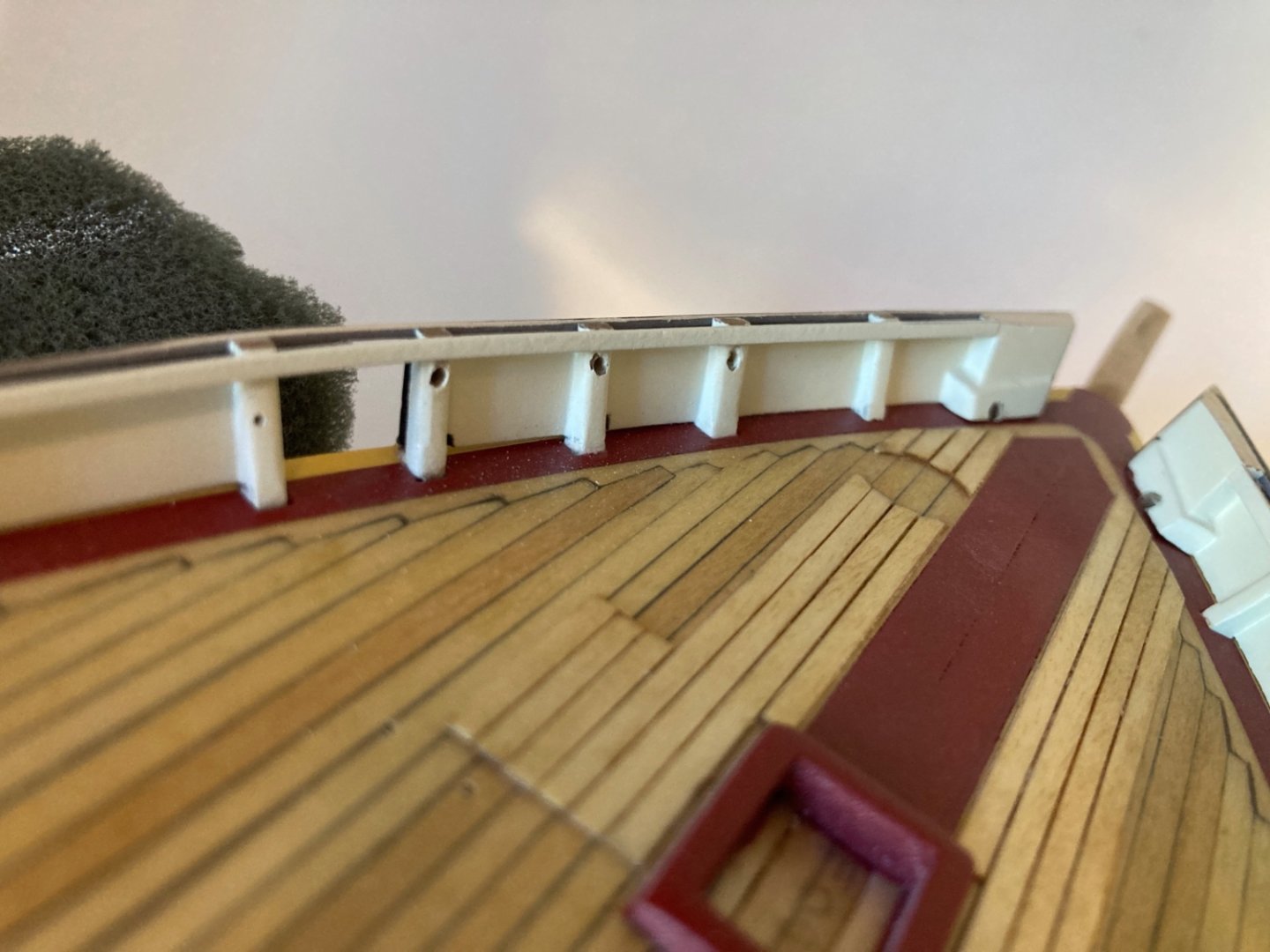
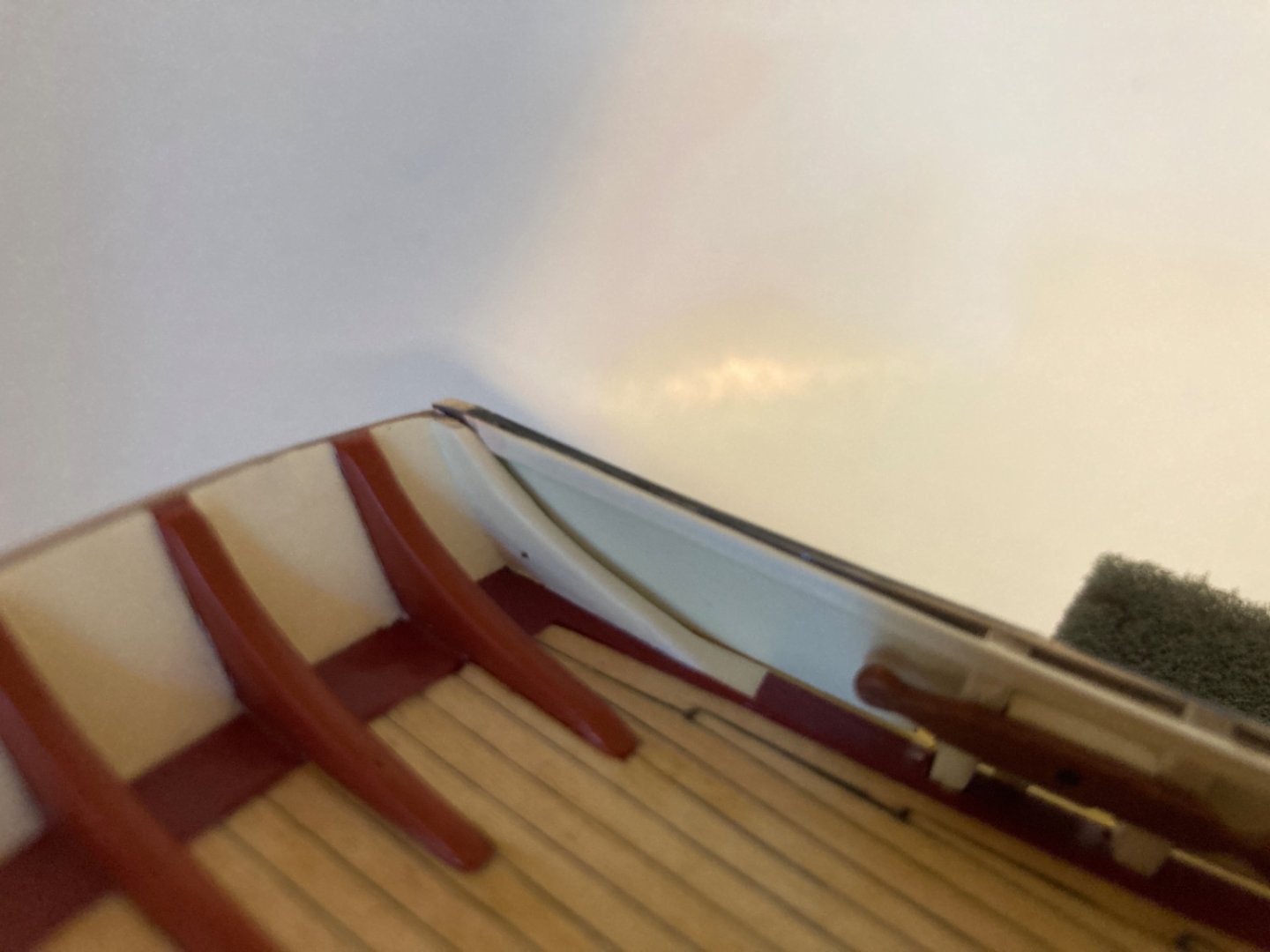
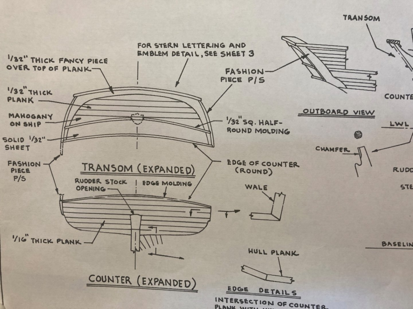
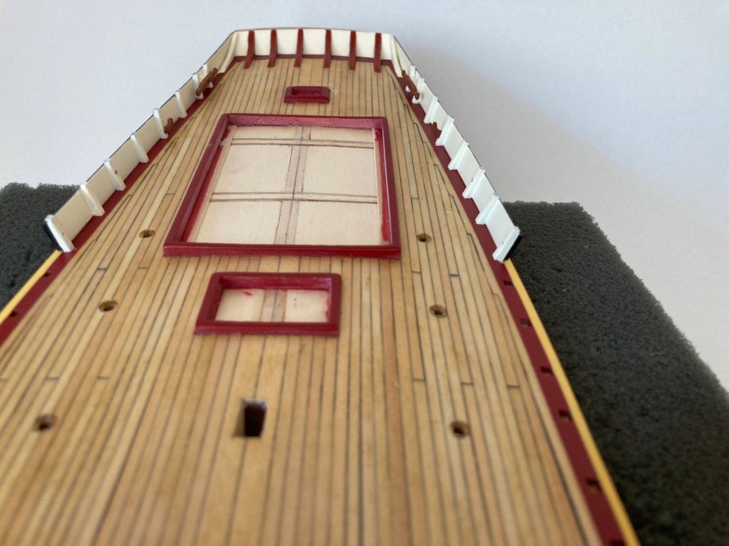
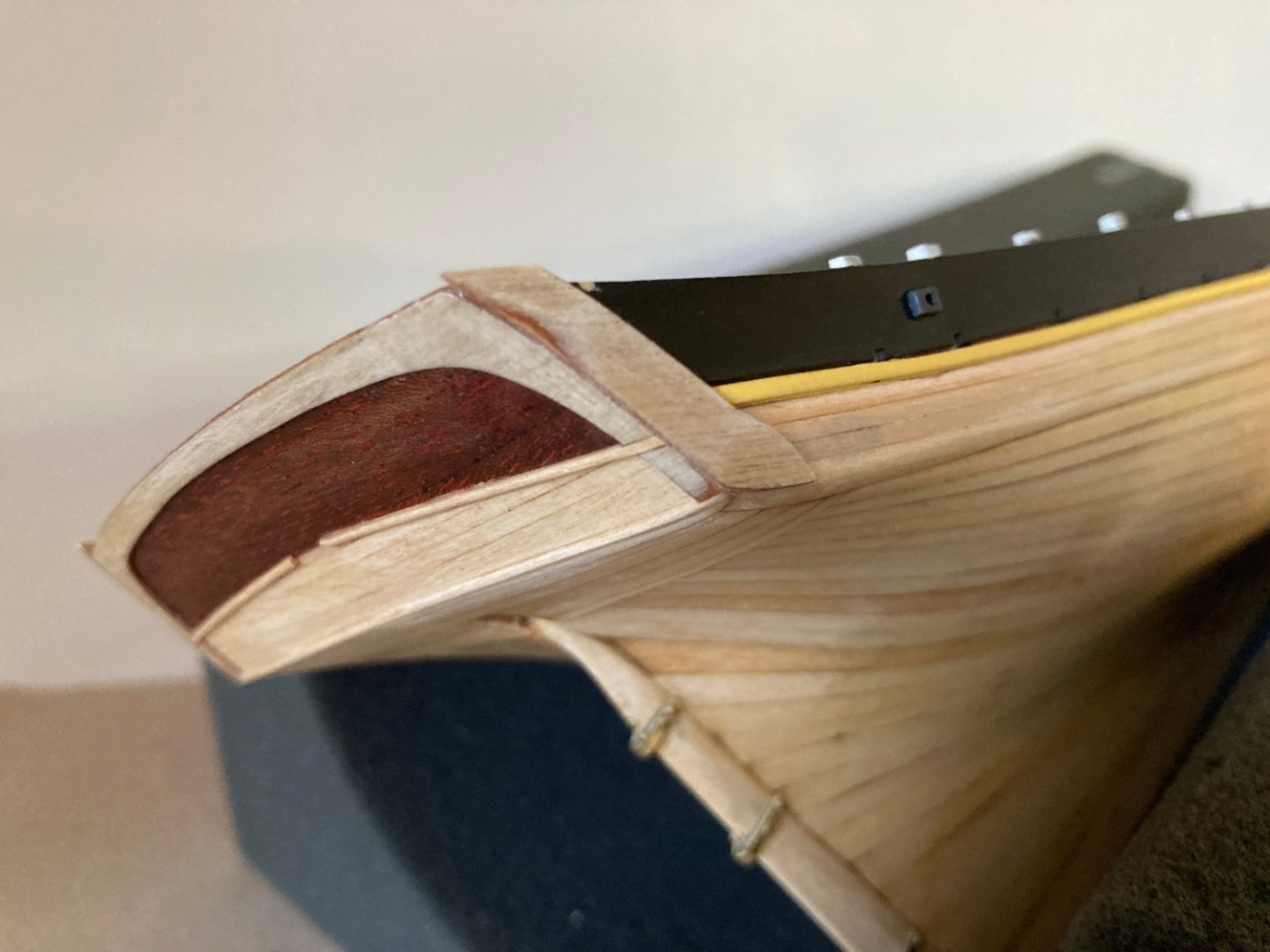
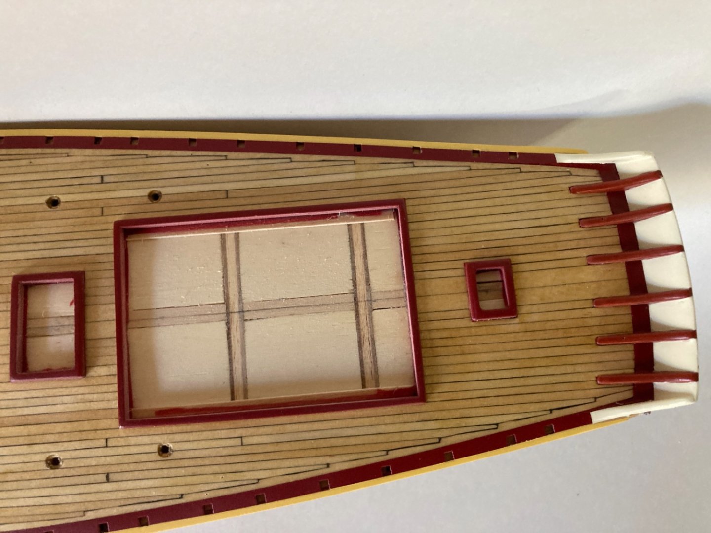
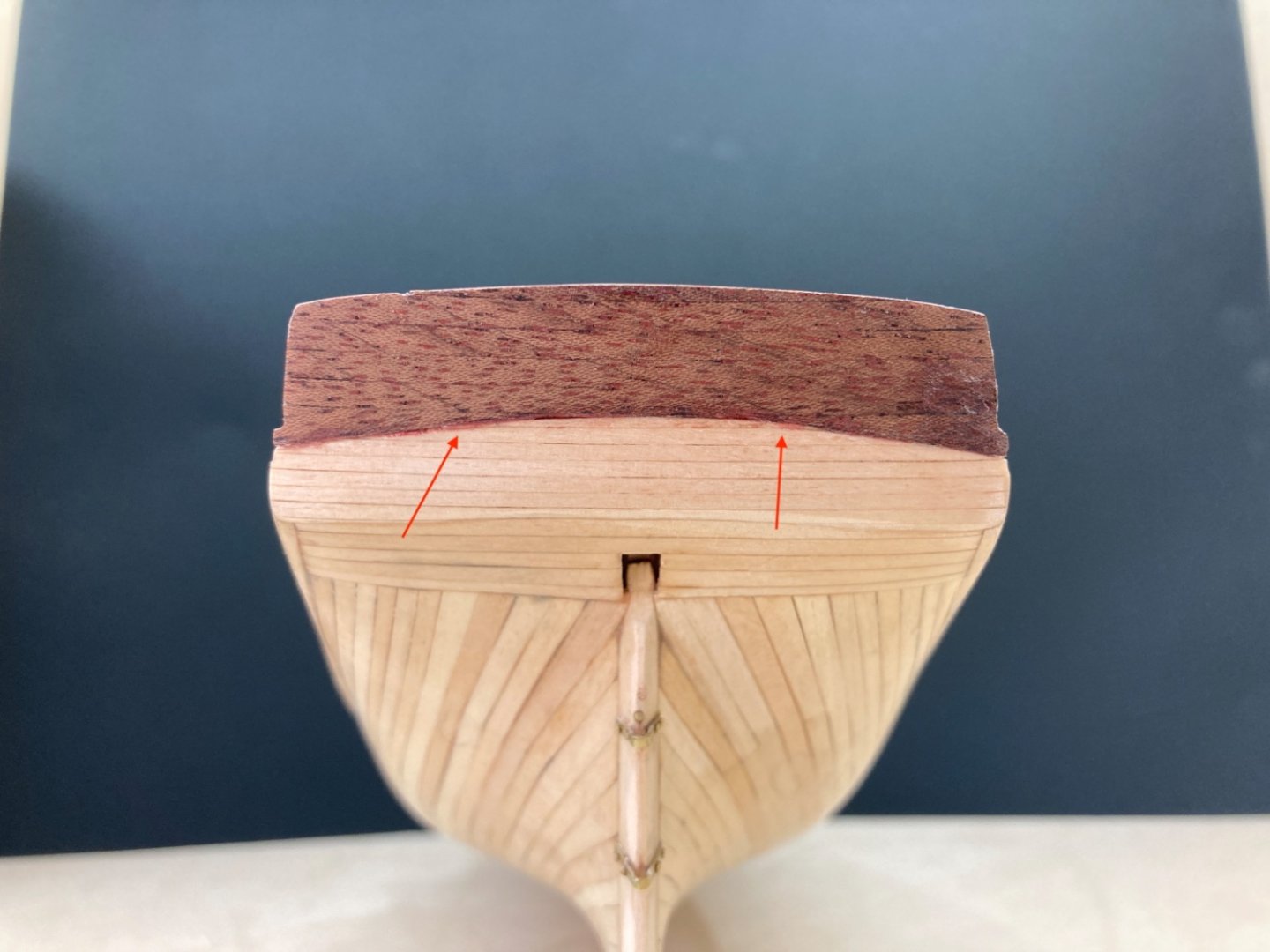
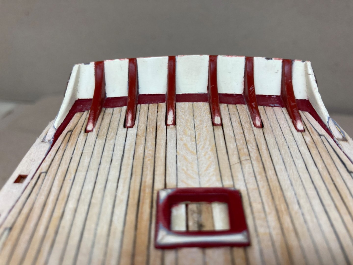
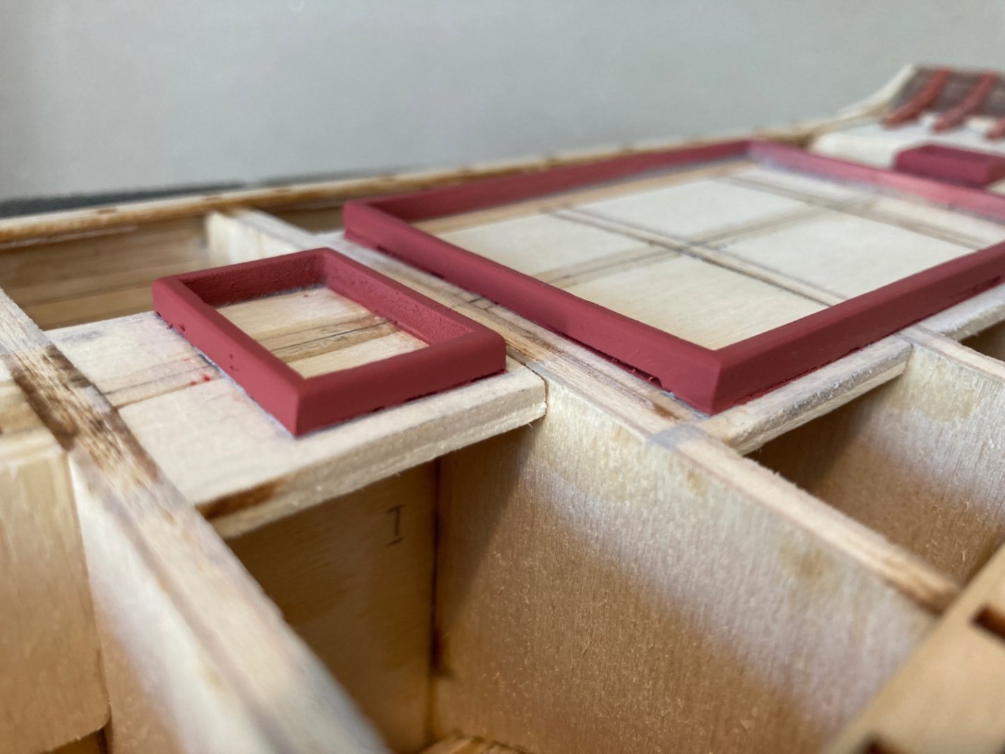
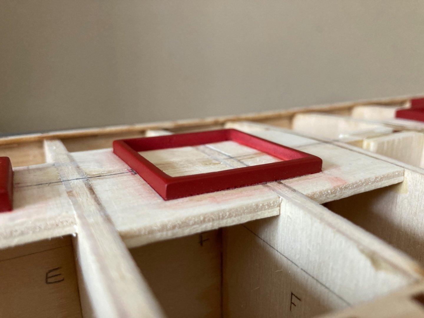
In the next step transom details like Fancy Piece and half round moldings were installed. Fancy Piece is prepared from 1/32 inch (0.8 mm) scrap wood. After fine sanding the edges of it to flush with the edges of transom, it was glued in place. Half round moldings were prepared from 1/32x1/32 inch (0.8x0.8 mm) stock and glued in place. Although the moulding at the border of counter and transom is one piece, the one at the border between upper and lower transom areas is interrupted leaving a small space in the middle for Maryland amblem which will be placed later. There was another structure called Fashion Piece and it was also prepared from scratch . As the Fashion Piece sits at the very aft end of the bulwarks on the bulwark planks , the installation of aft bulwarks is necessary to begin with. That was what I did and I installed the two aft bulwark sections (section 6) on both sides first. After the installation of the aft bulwarks I noticed that the bulwark section on port side showed more inclination towards outboard when compared to starboard side. The angle formed by the bulwark and deck was wider. There was another problem. On both sides and when you look from almost an horizontal view angle you notice a space between the bulwark and deck level. In the photos below the space can not be seen. However from a certain angle one can easily spot them. The installed bulwark sections were the longest ones and there was 8 stachions in each of them. Also they are a bit curved towards the stern in order to fit the sheer line. Those factors probably caused the faulty result. I tried to install the bulwark sections again but nothing changed. So I made peace with the model and moved on. The Fashion Piece was fine sanded and glued in place. Port side Starboard side


- 114 replies
-
- 2
-
-
- Pride of Baltimore II
- Model Shipways
- (and 1 more)
-
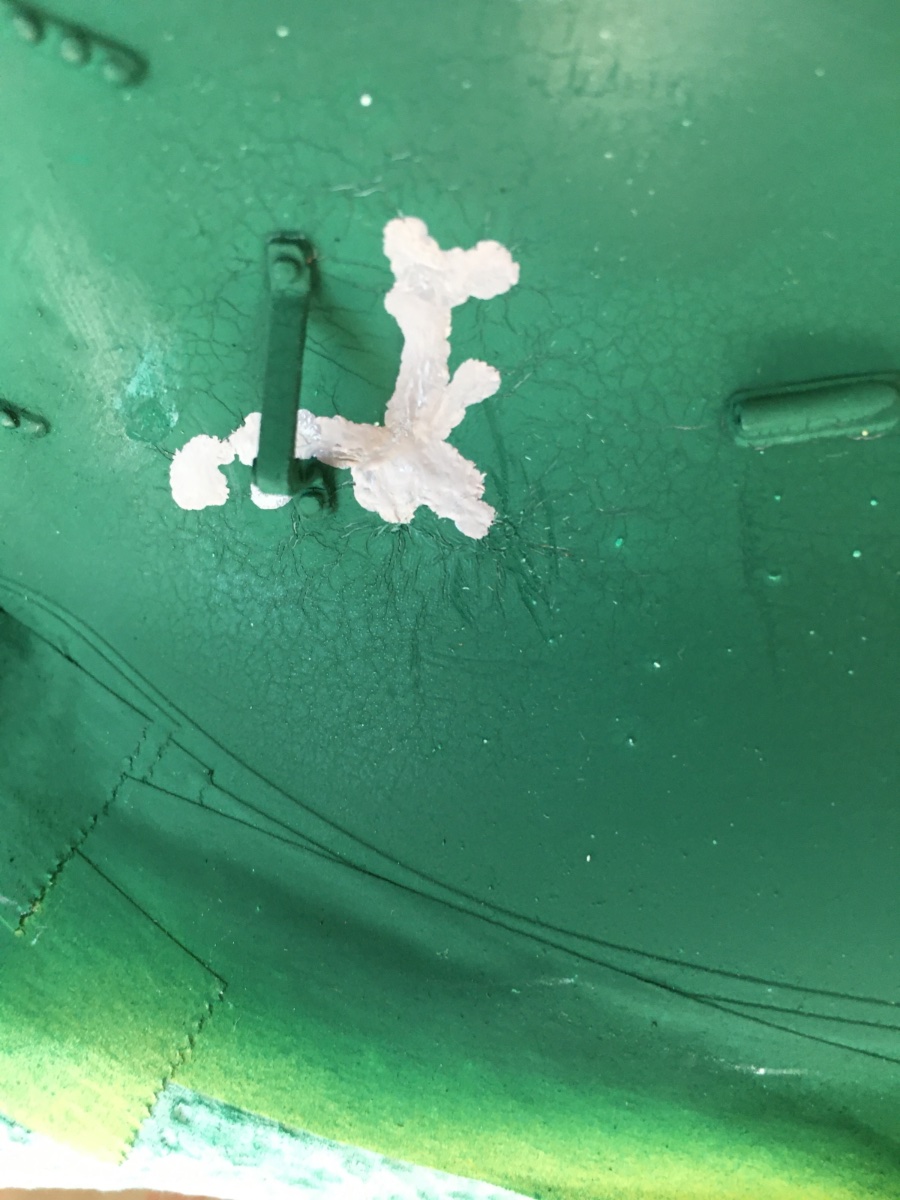
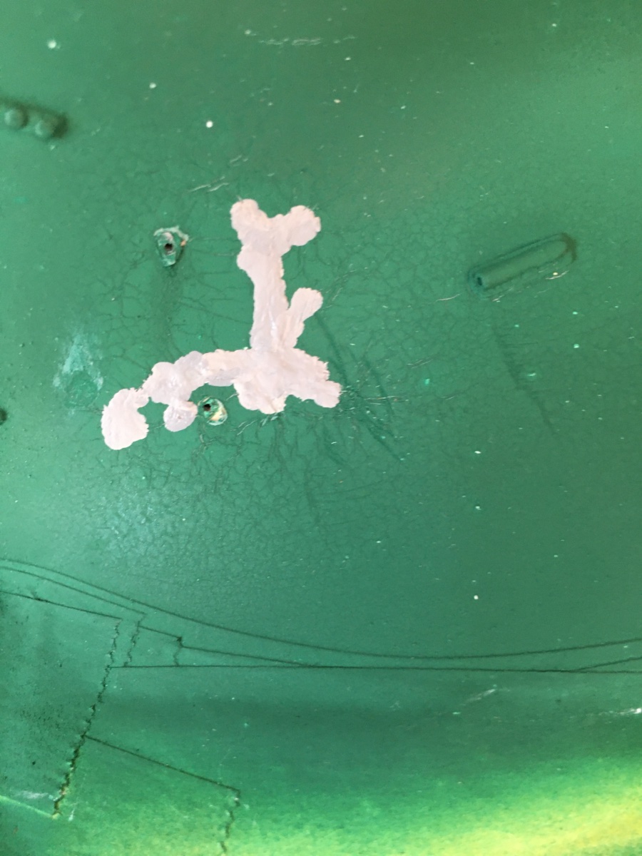
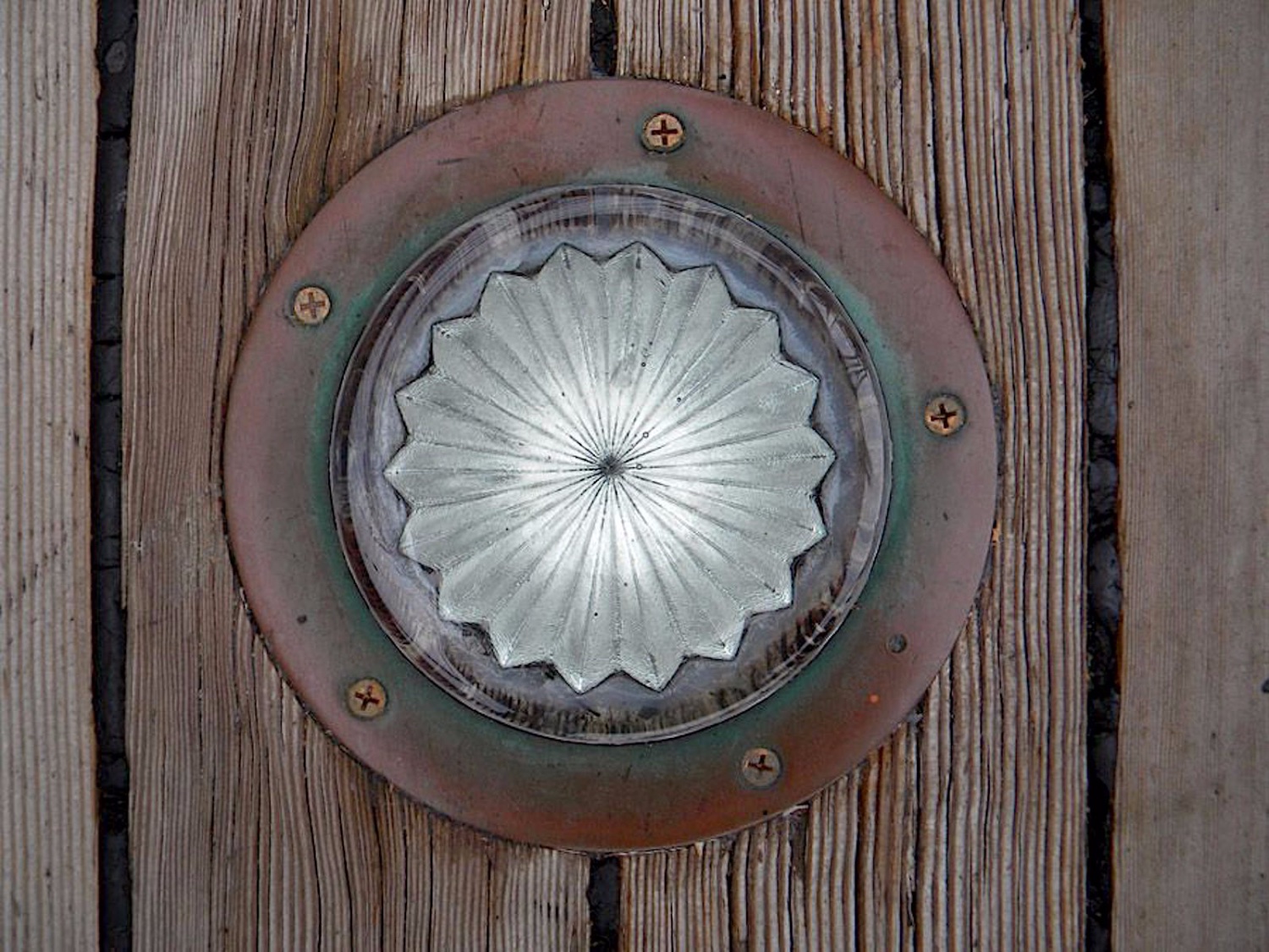
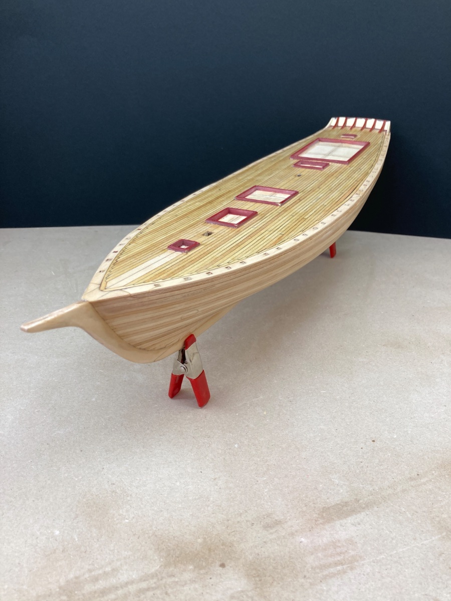
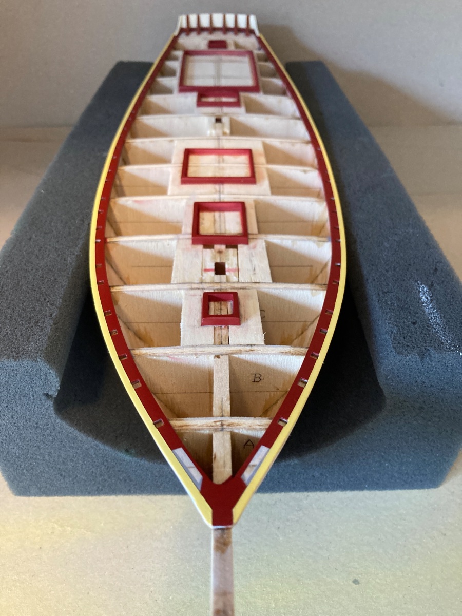
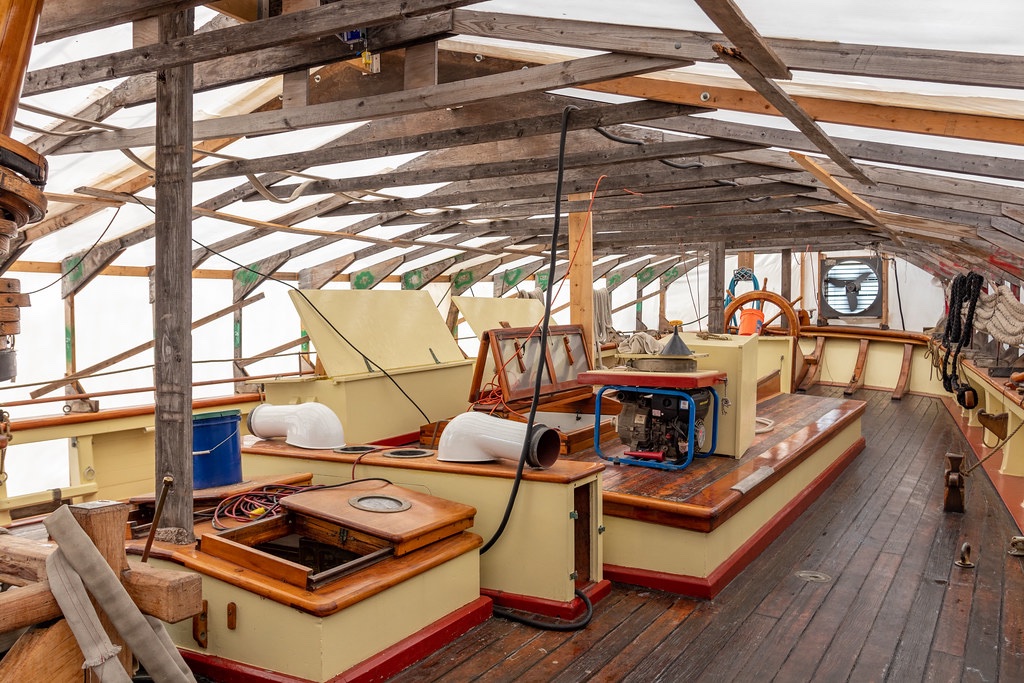
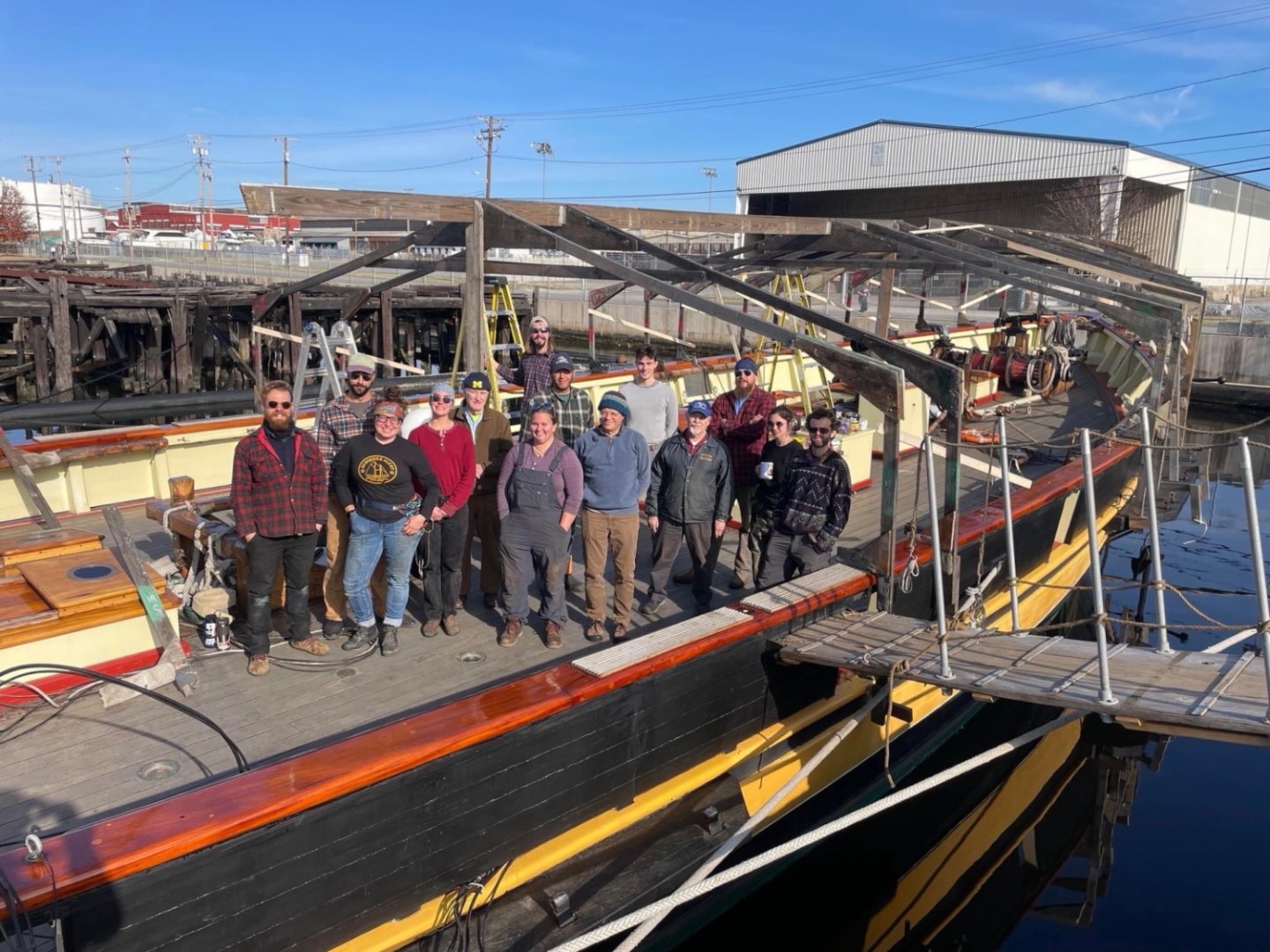
Hello Yves, Thanks for your comment. Those prisms are light tunnels to bring sunlight in the lower decks just like you said. Here is a photo from the real ship. I was not happy with them also but I could not find any other alternative at that time besides using smaller scale ones. They were also used in some other pars of the model. However I used plexiglass ( also used for window glass) from previous projects to simulate window glass in some other parts of the model but was unable to cut so small and circular pieces from them to replace the prisms. French modelers led lights are a clever and superb idea... By the way I kindly remind you that this model is already finished and this is a retrospective blog. The link for the finished photos of the model Wish you a happy and merry Christmas Eve and Day later tomorrow.

- 114 replies
-
- 1
-
-
- Pride of Baltimore II
- Model Shipways
- (and 1 more)
-
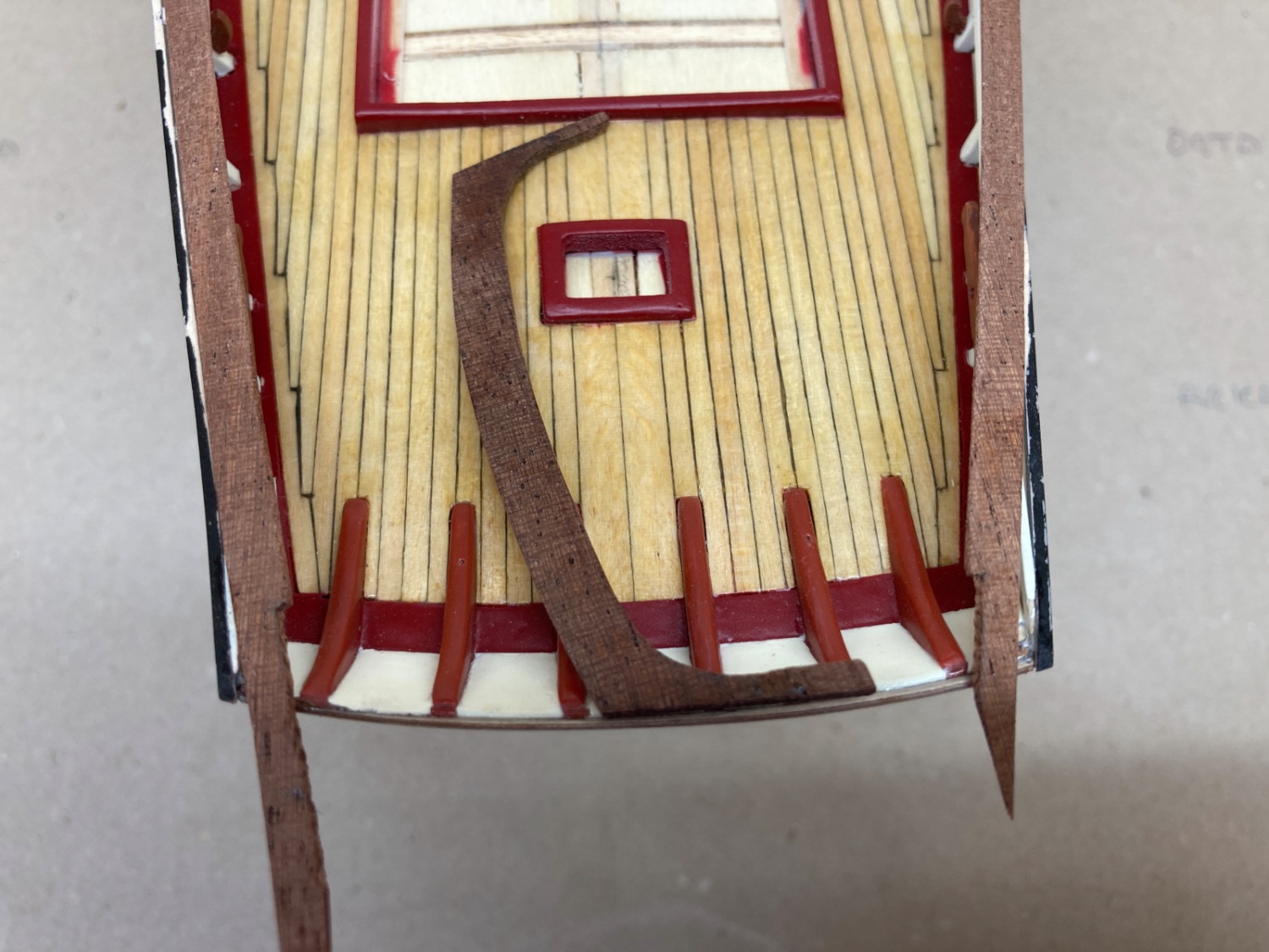
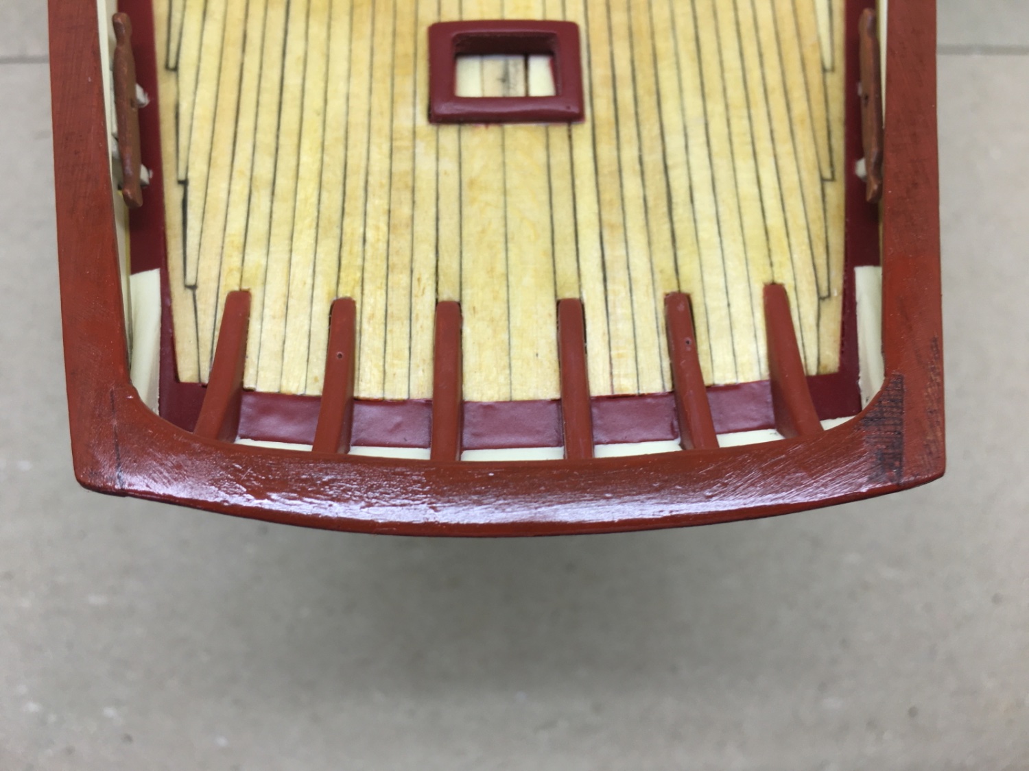
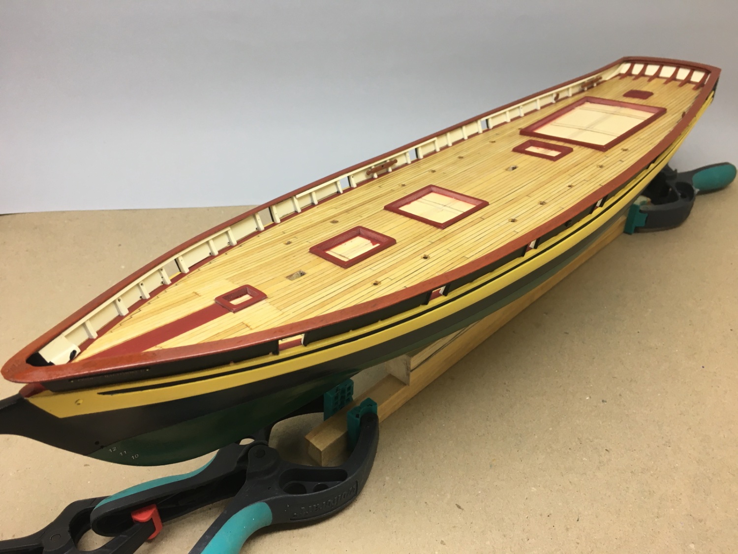
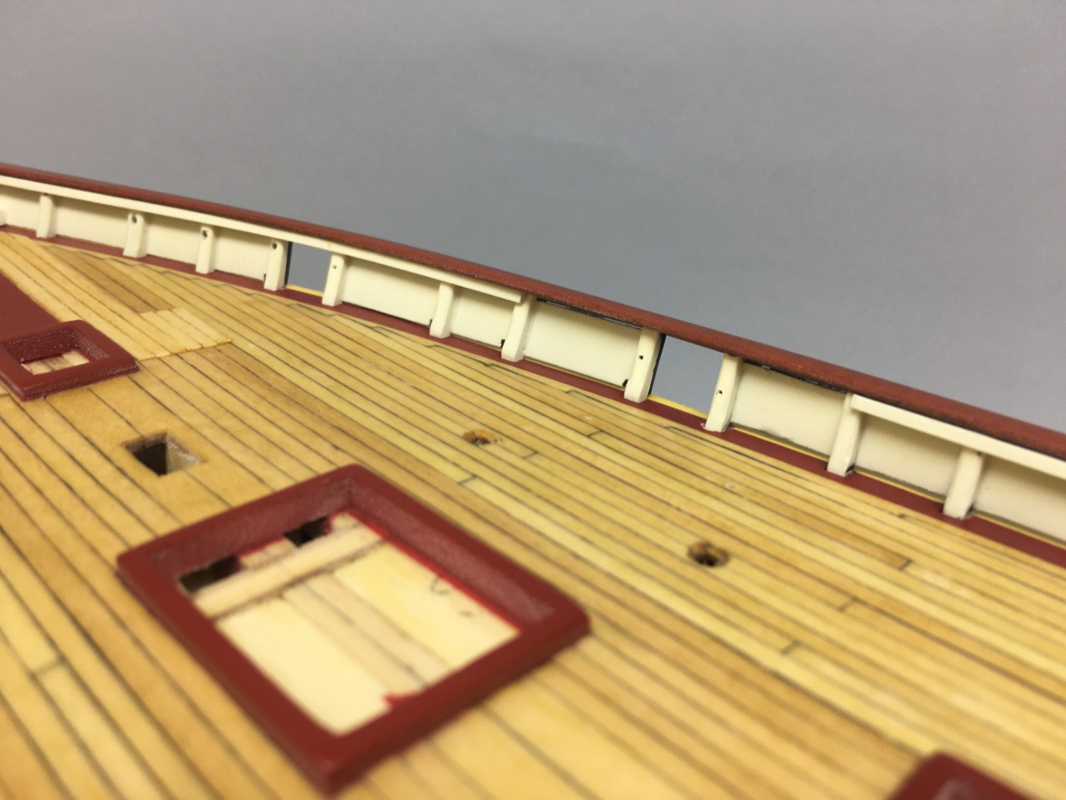
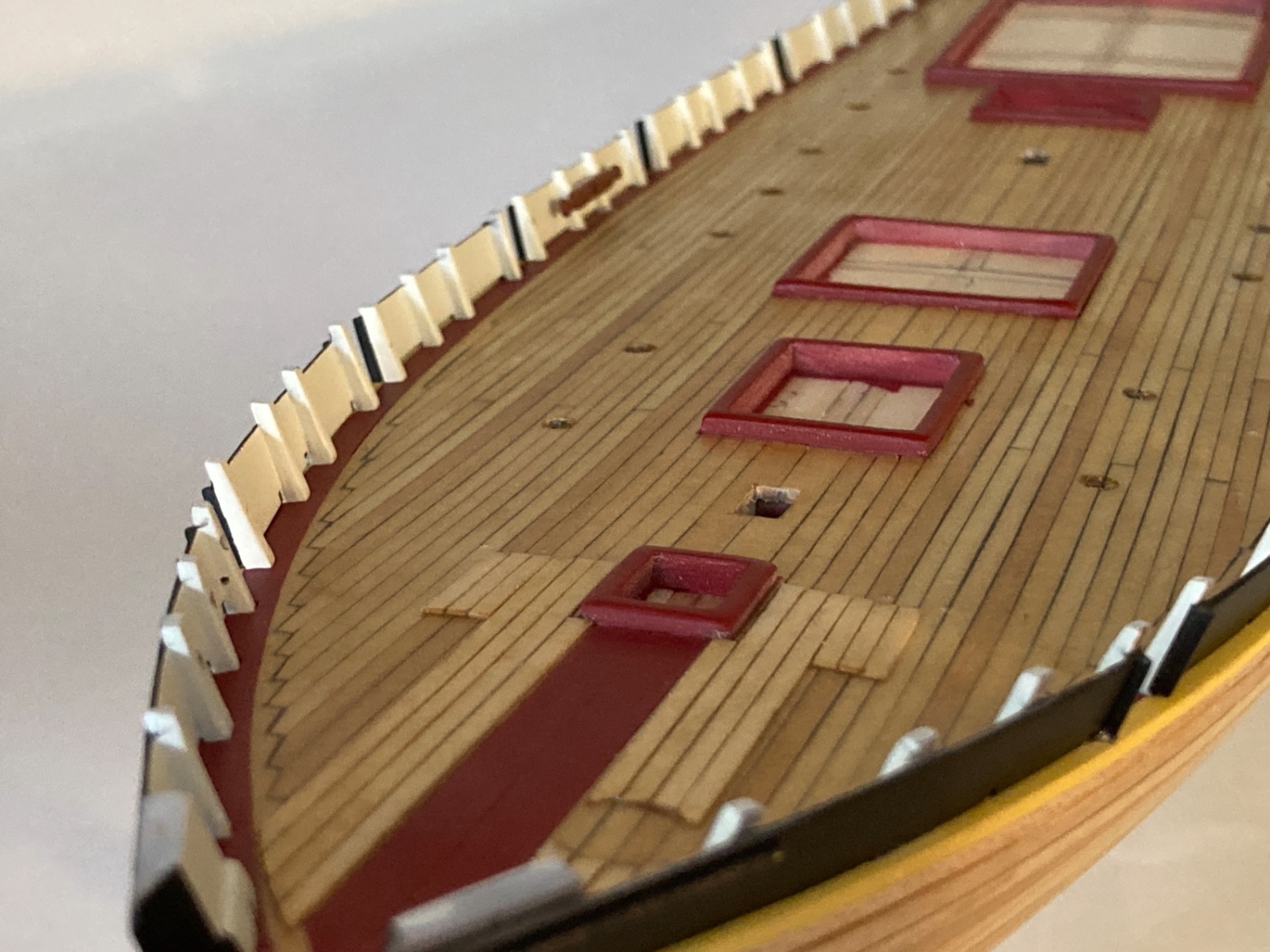
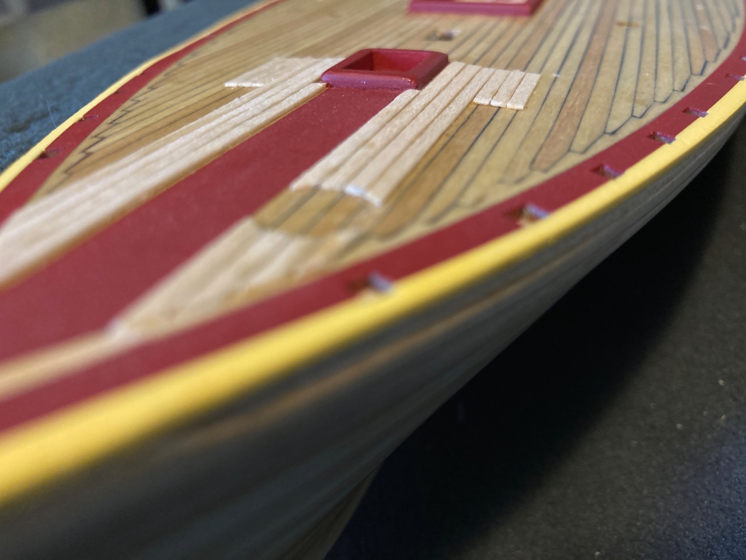
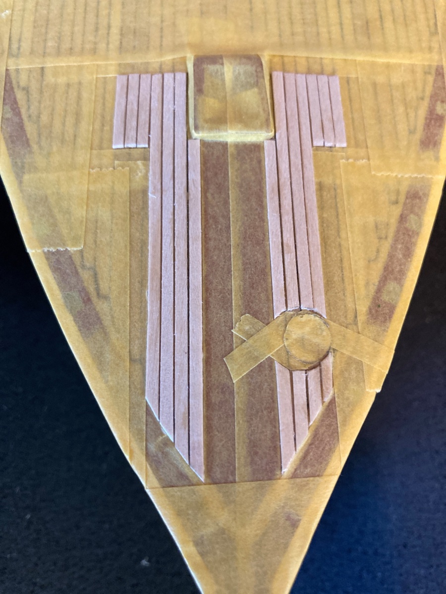
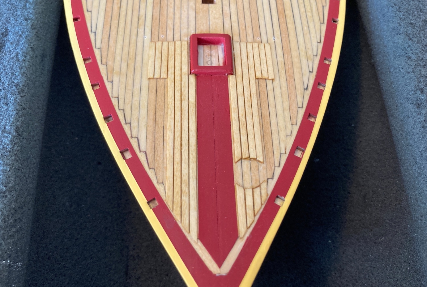
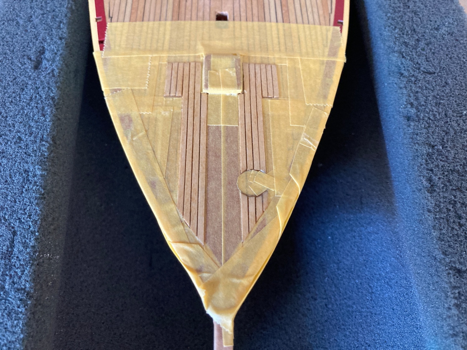
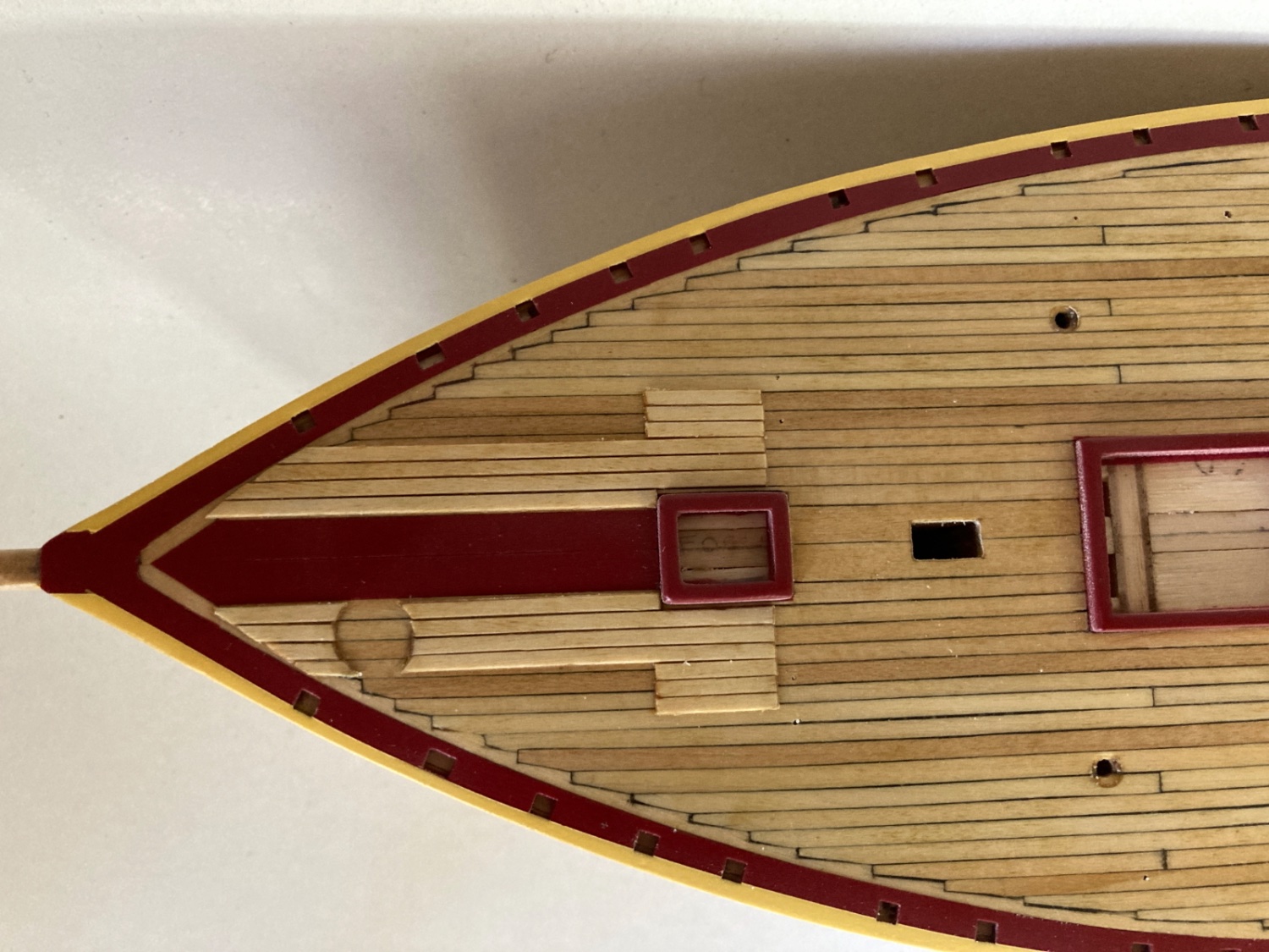
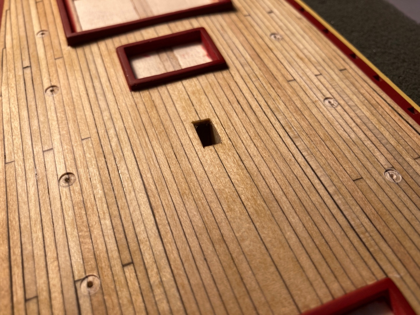
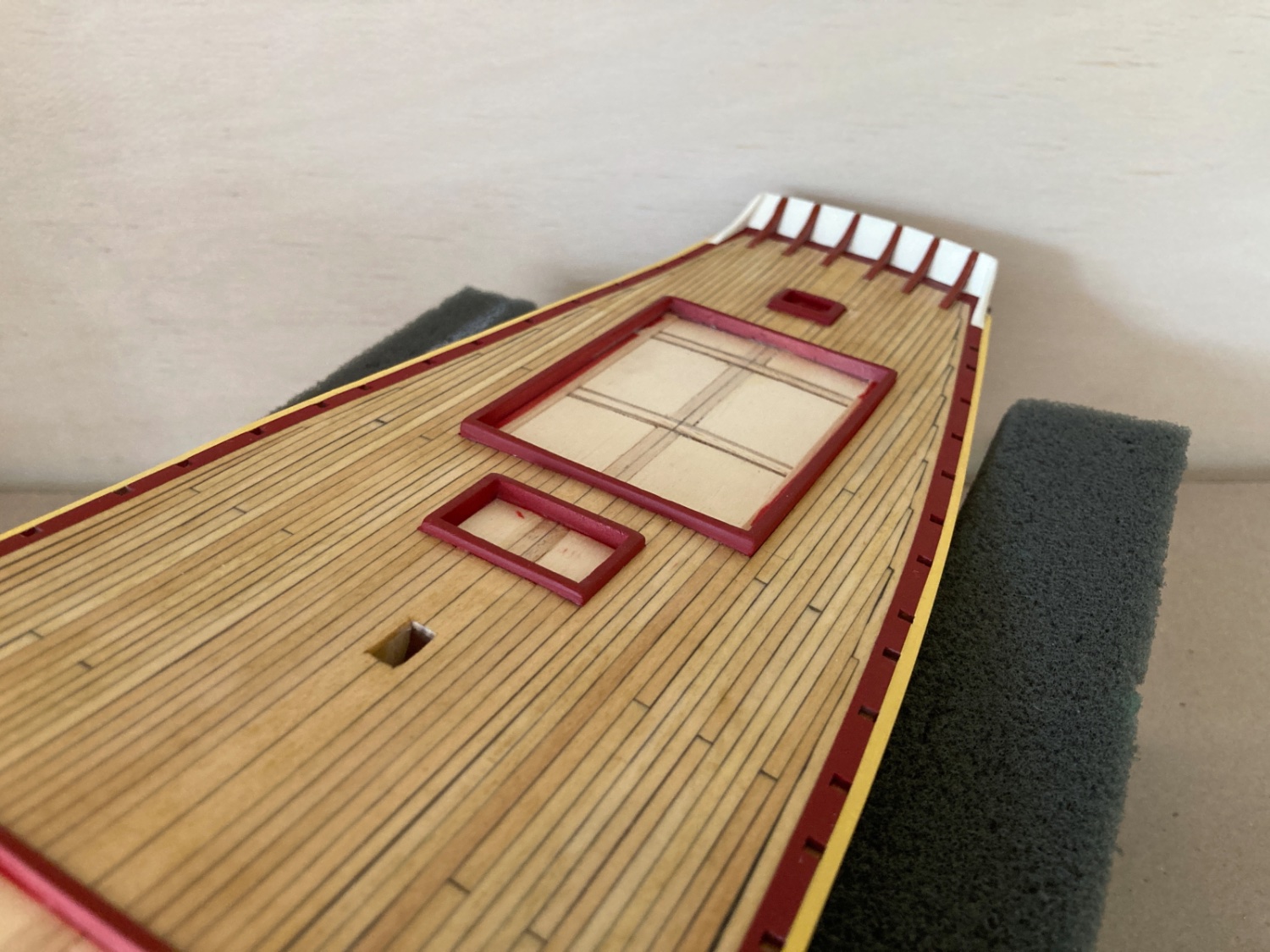
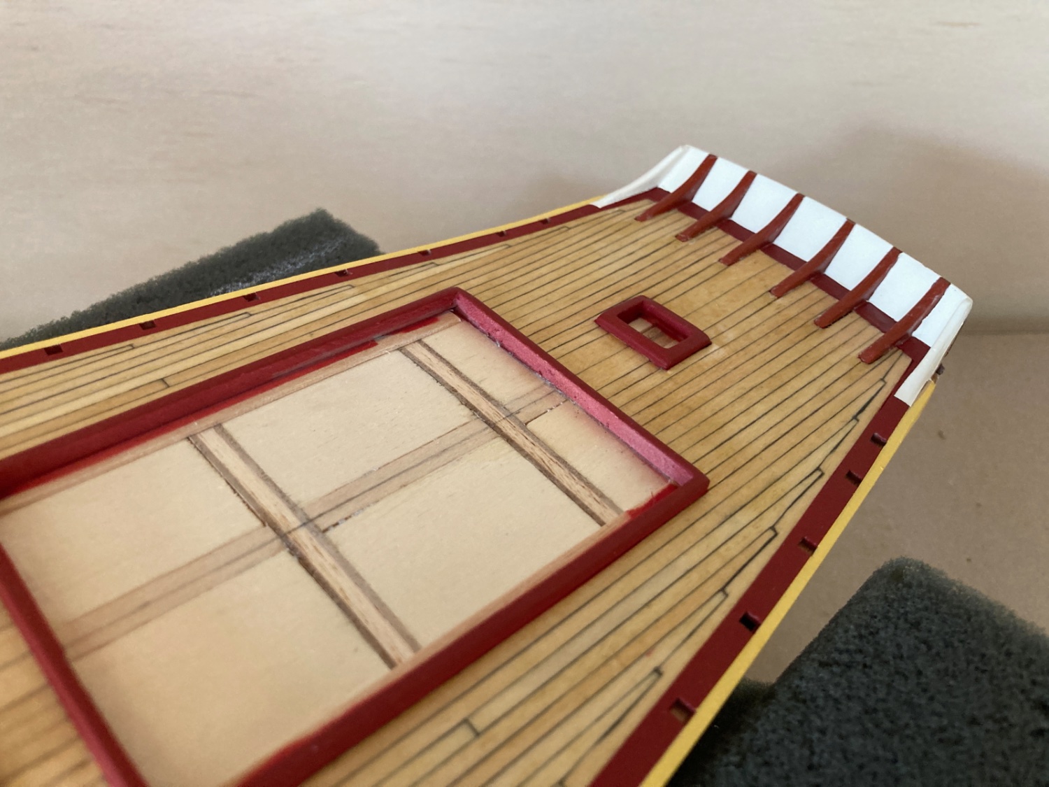
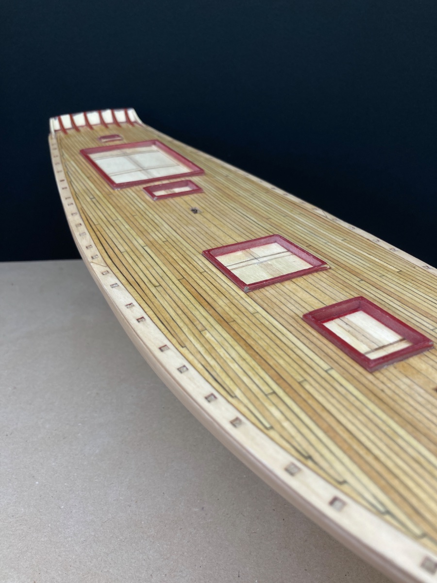
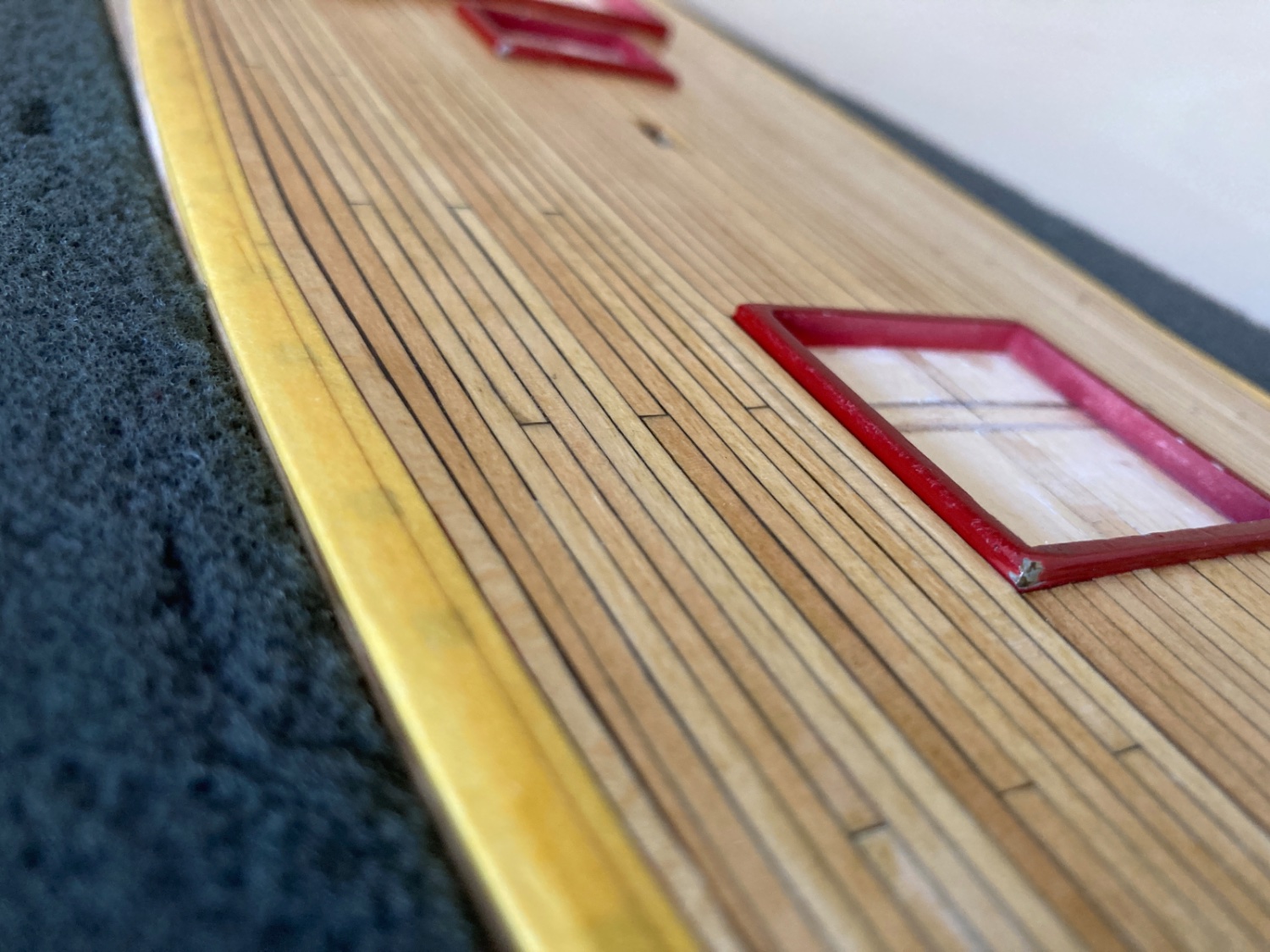
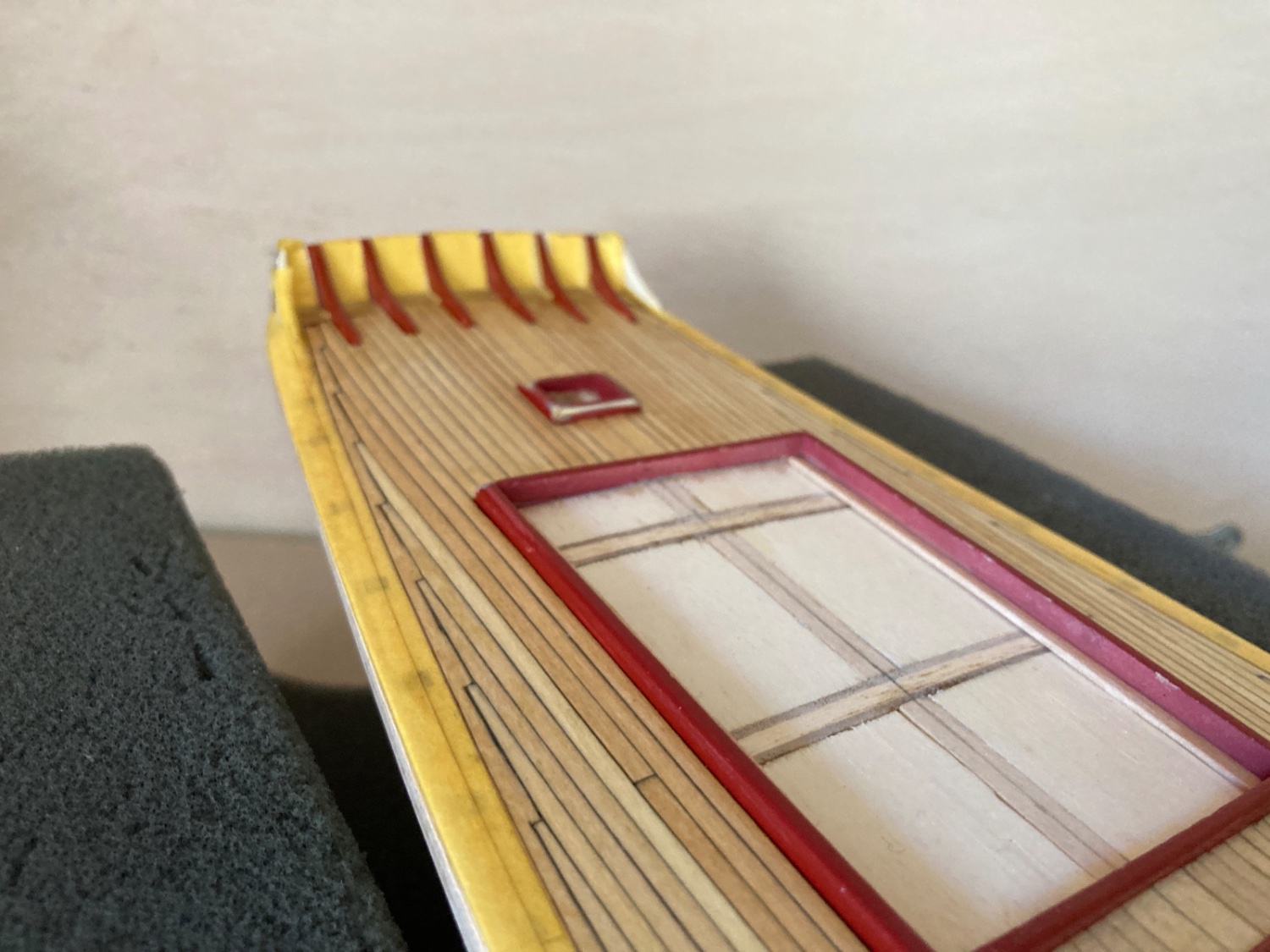
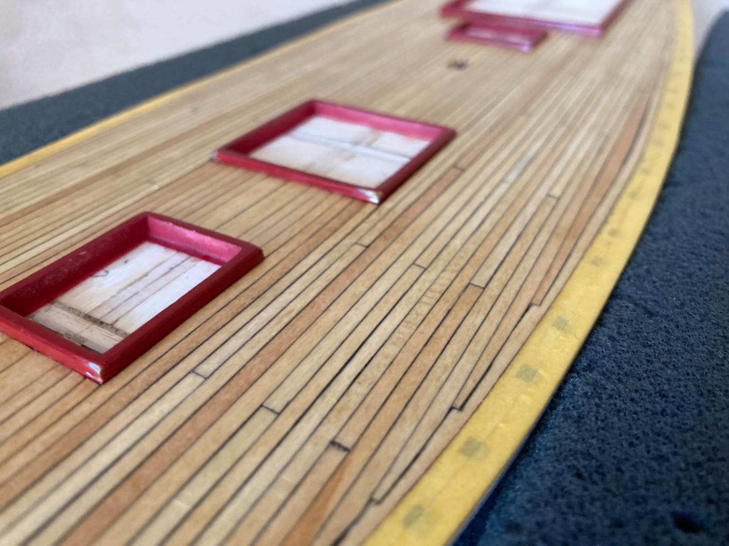
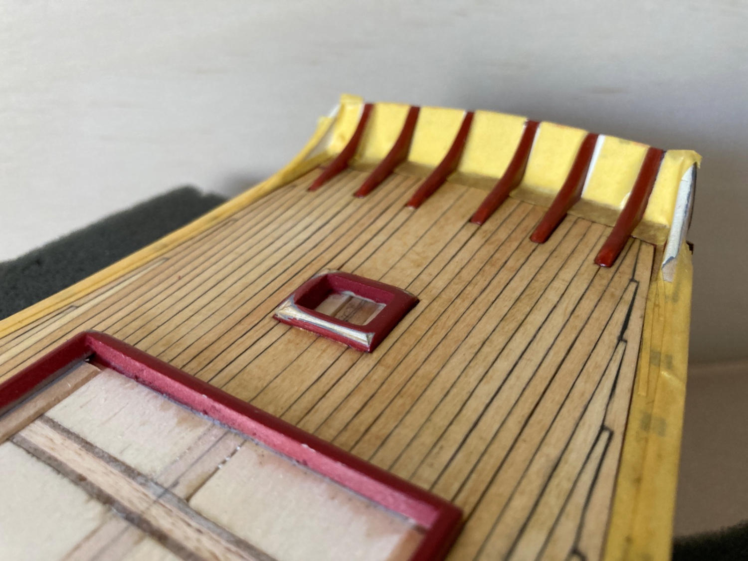
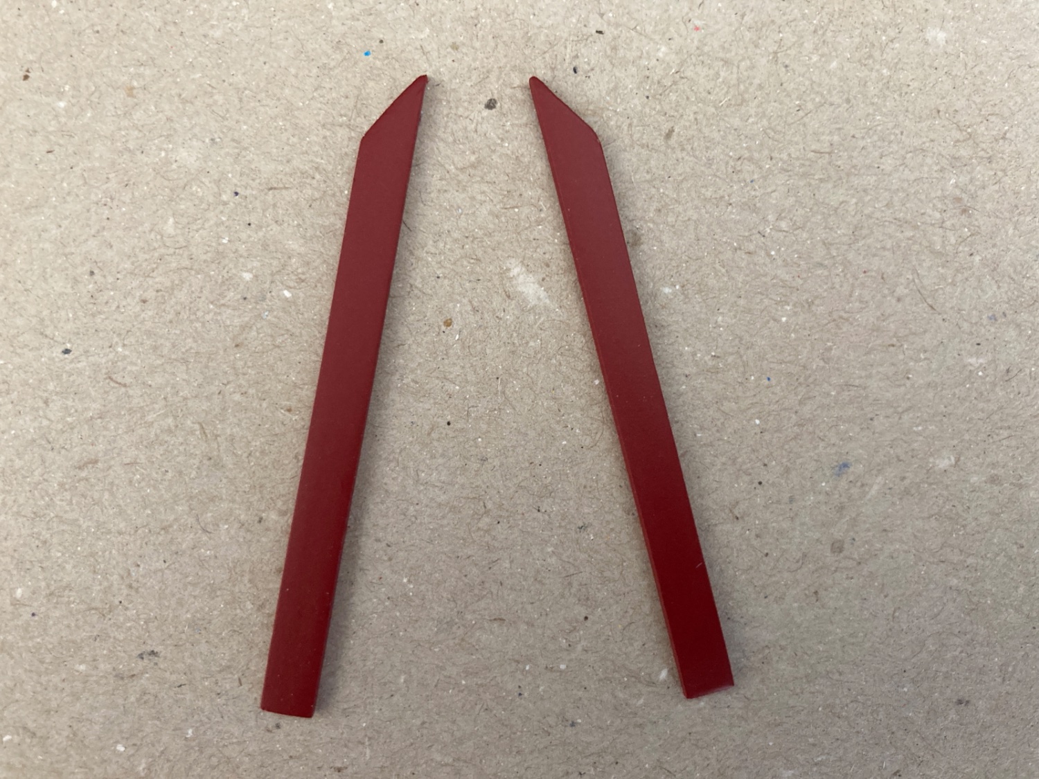
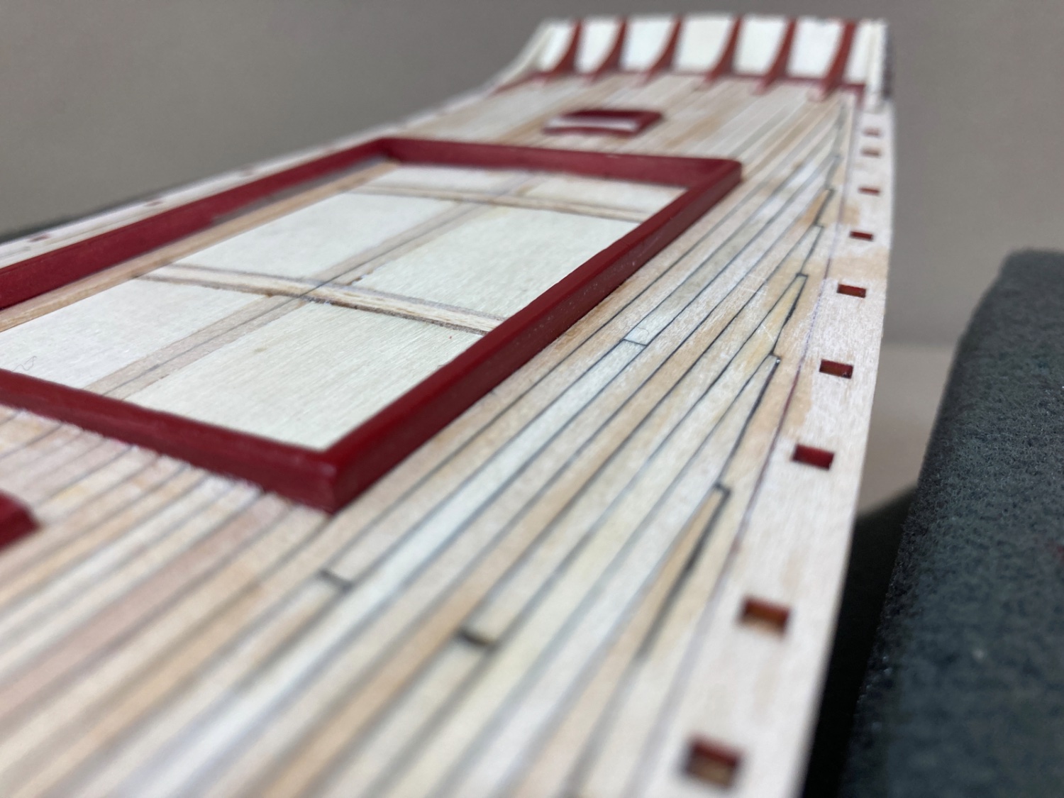
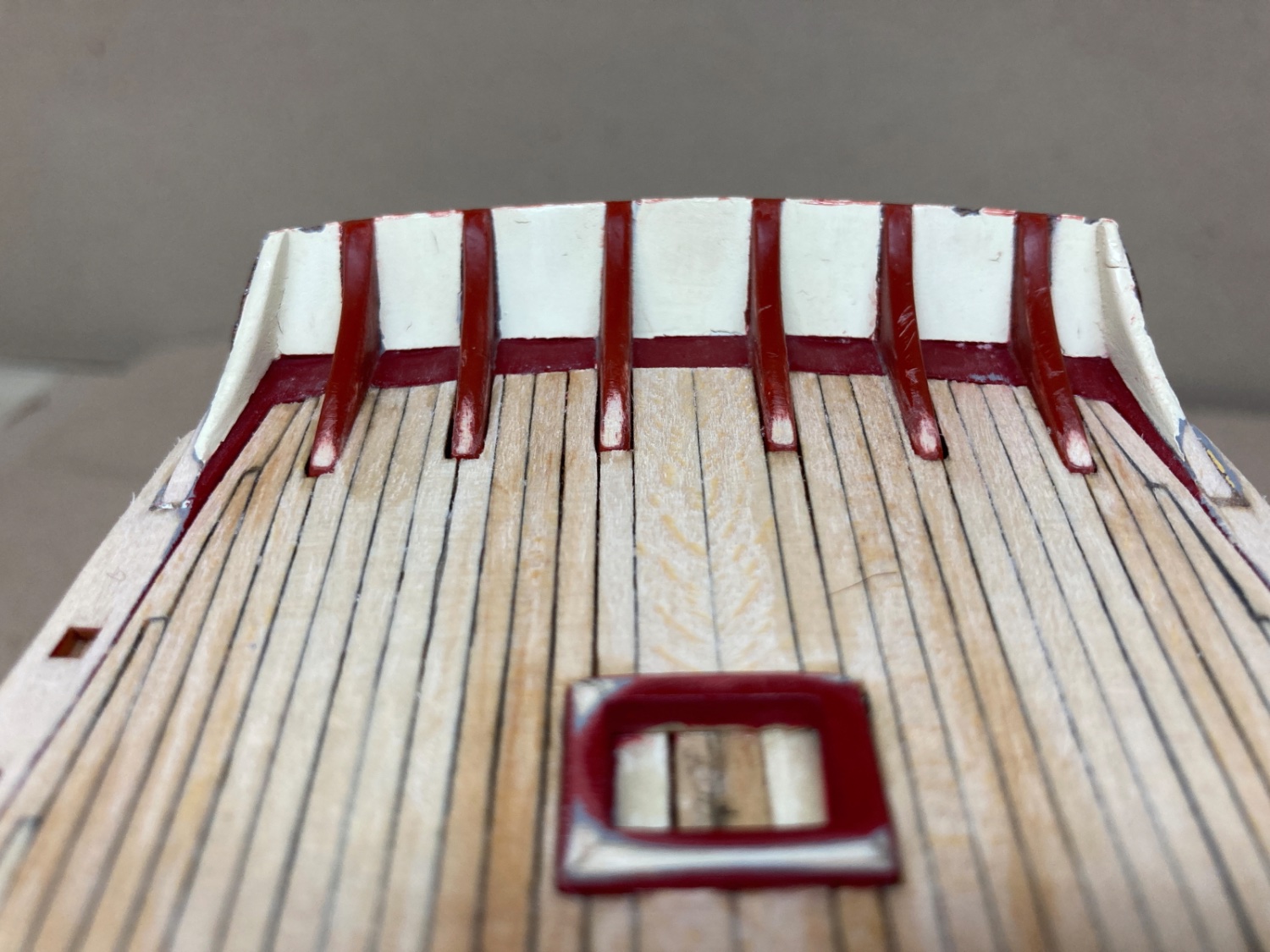
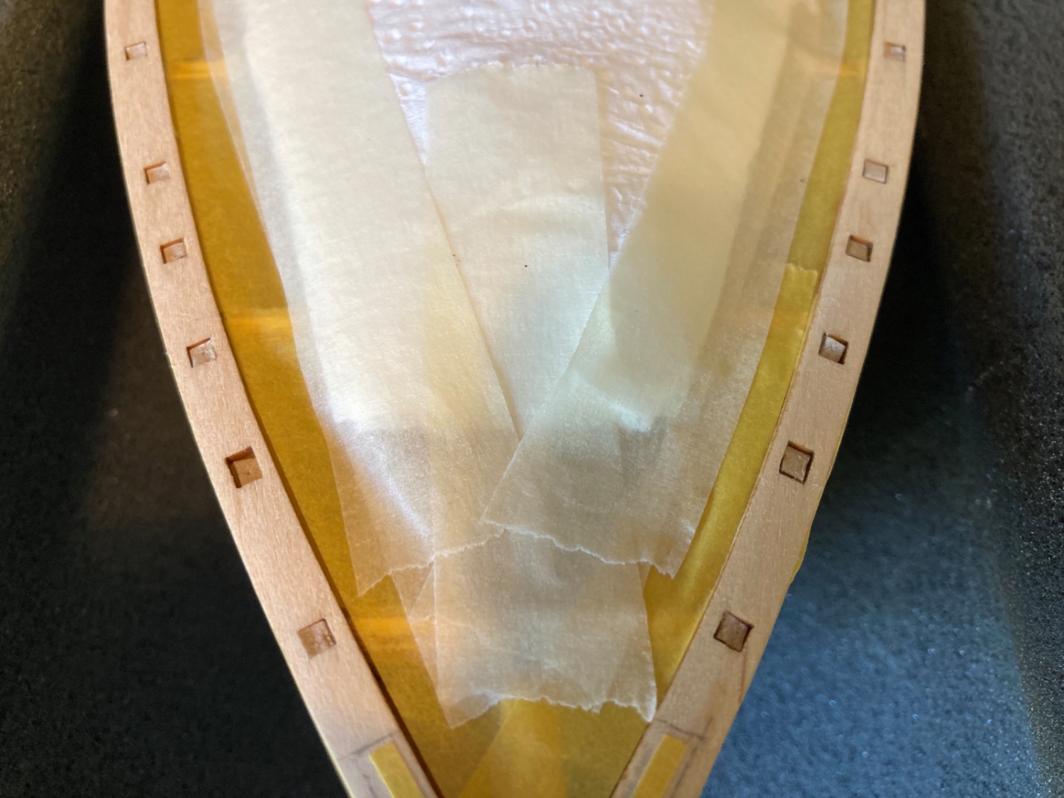
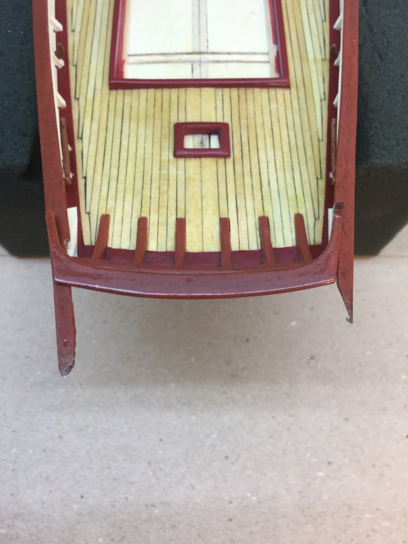
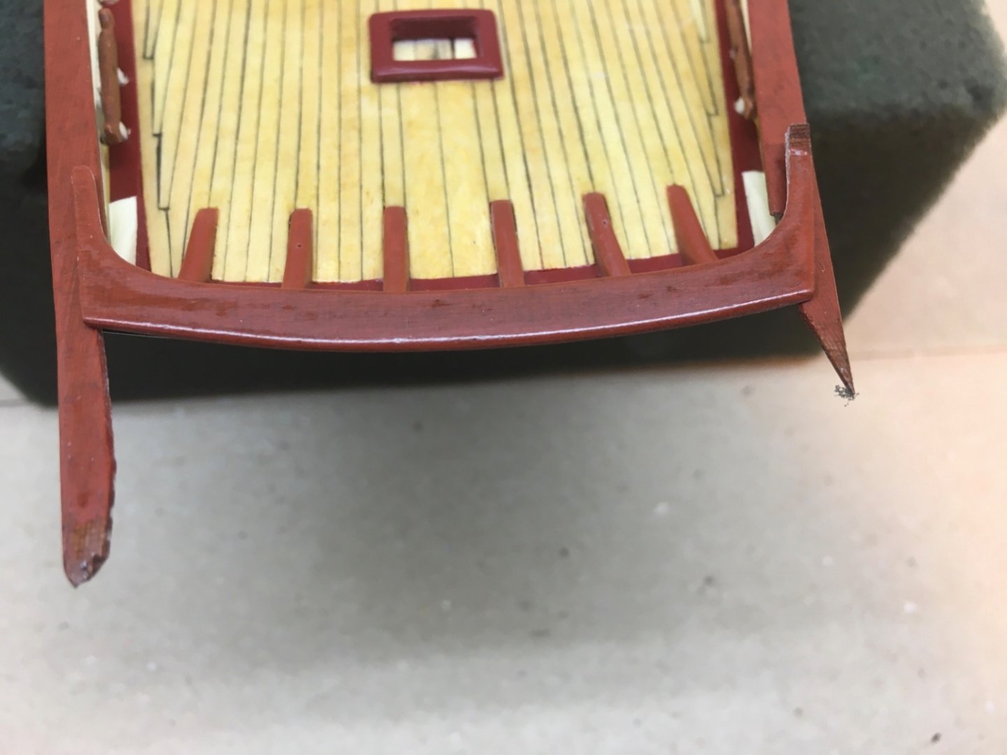
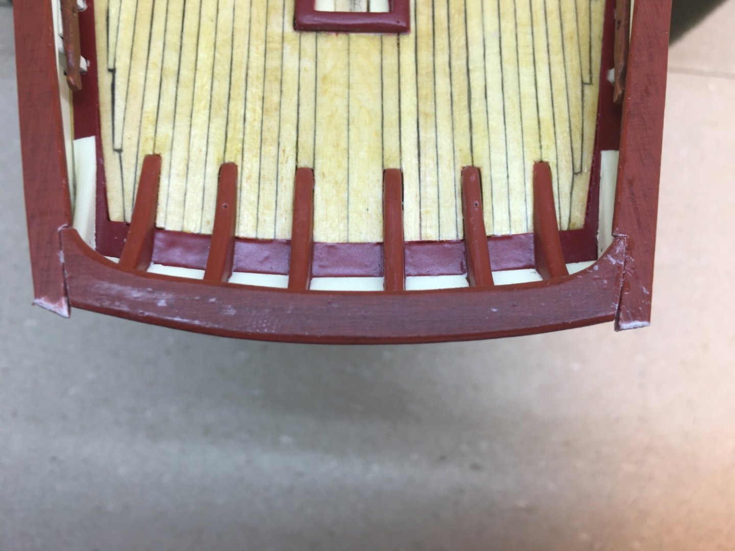
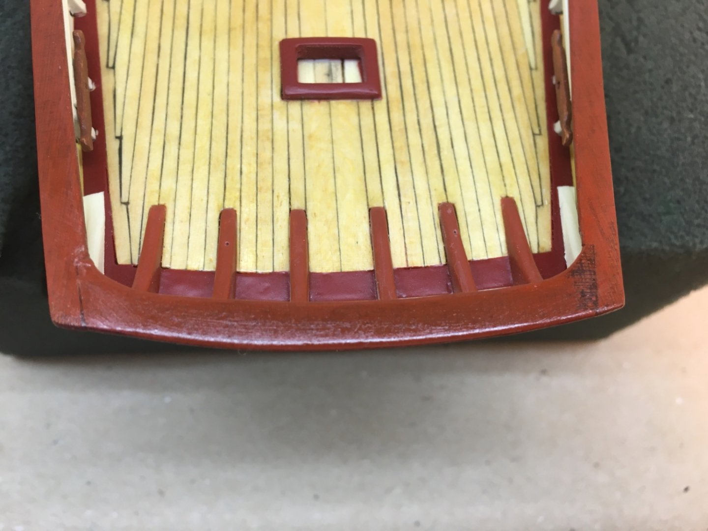
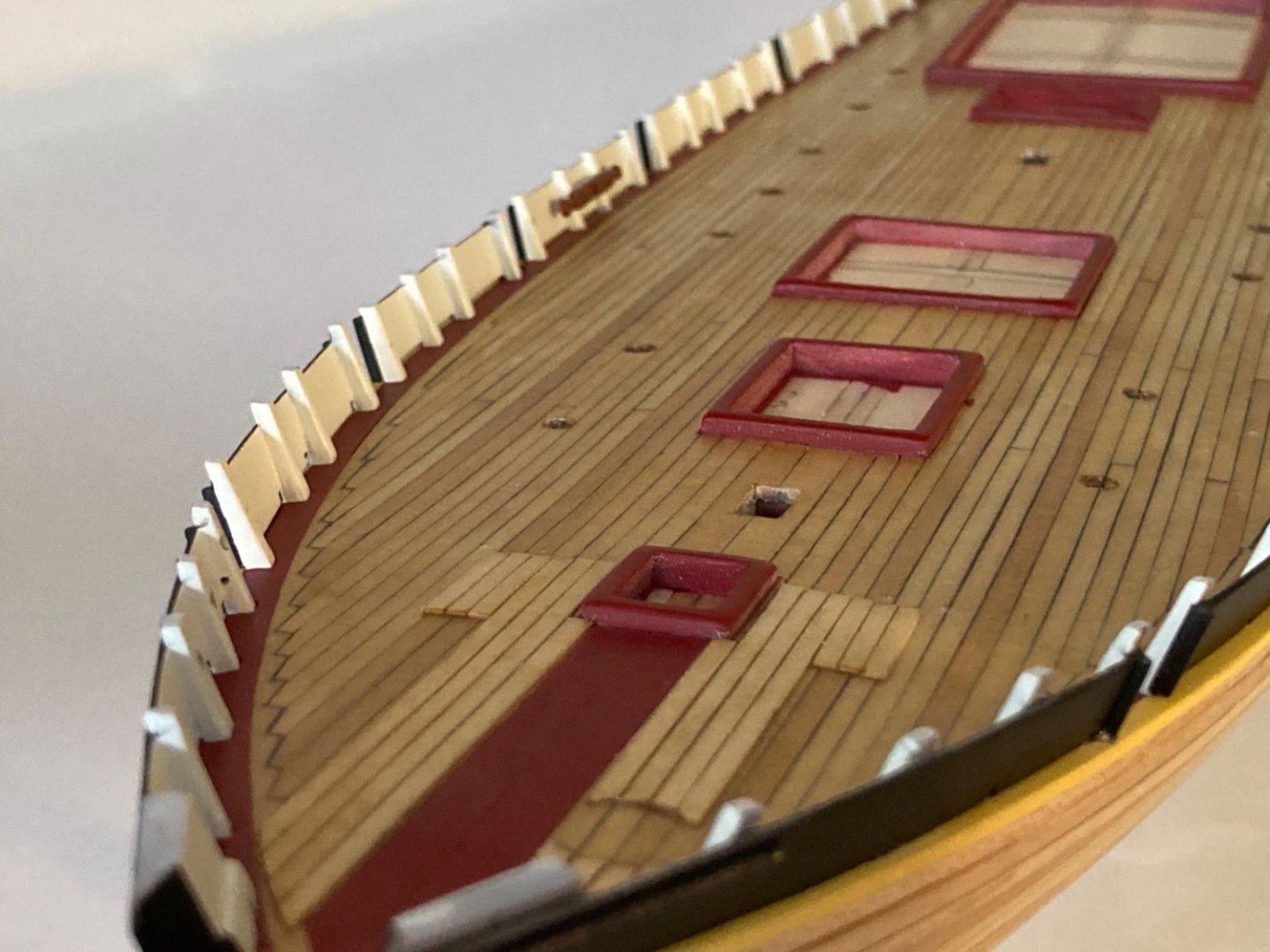
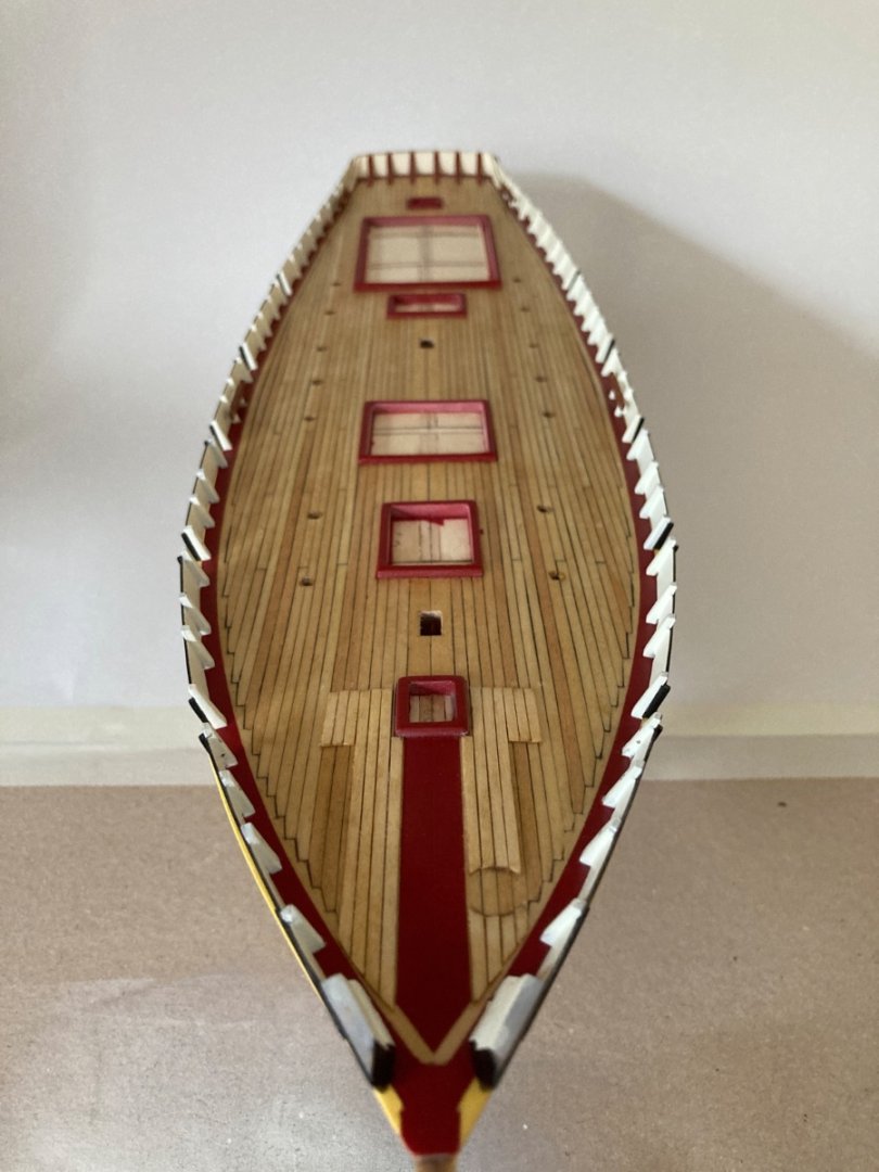
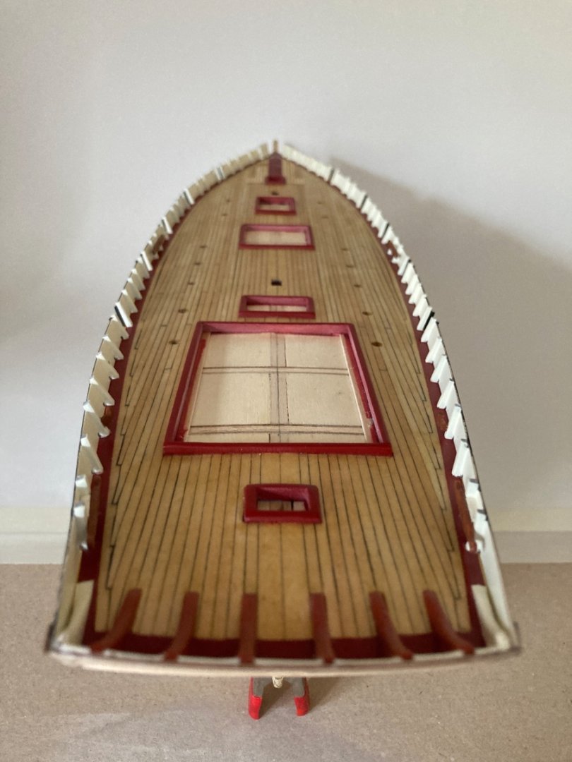
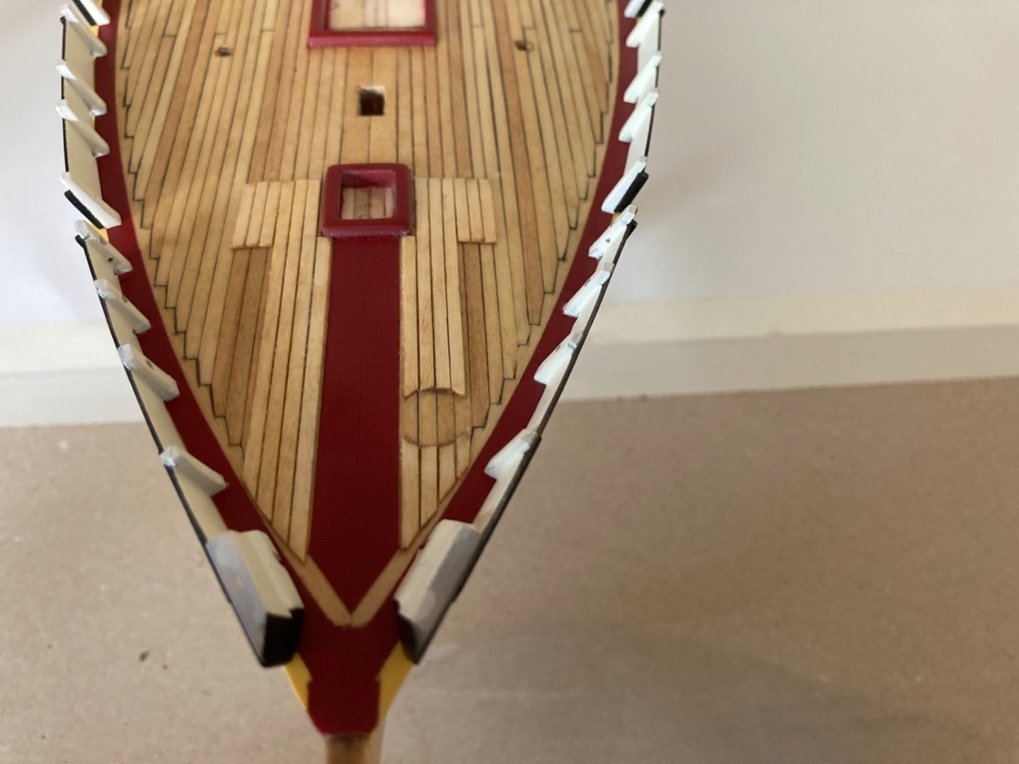
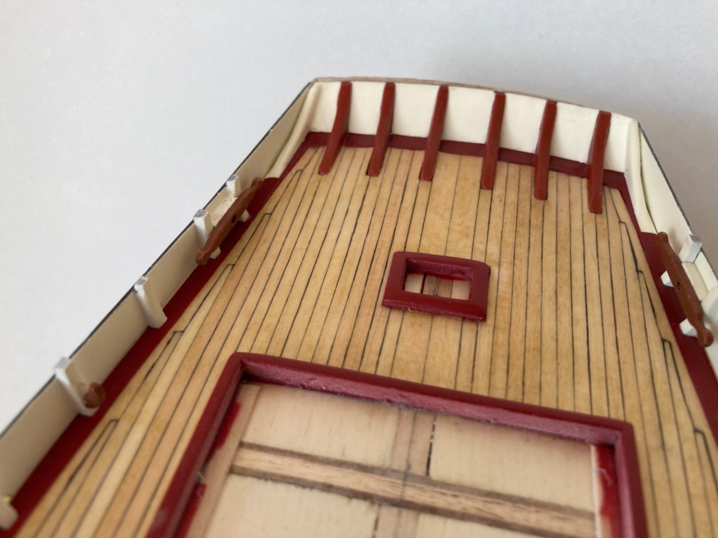
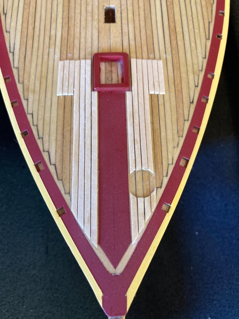
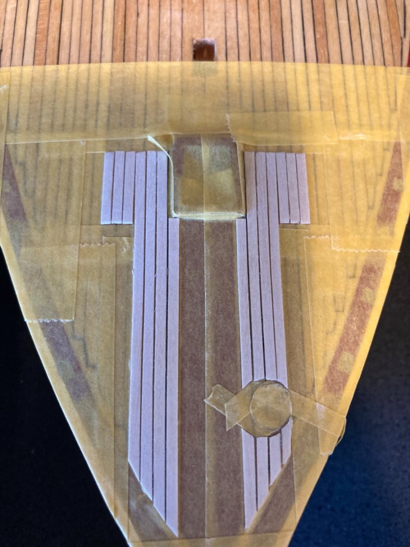
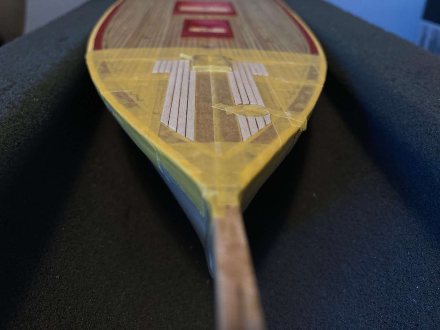
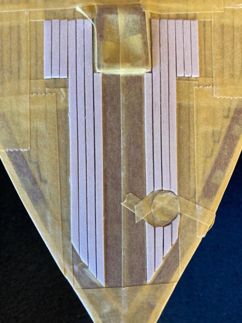
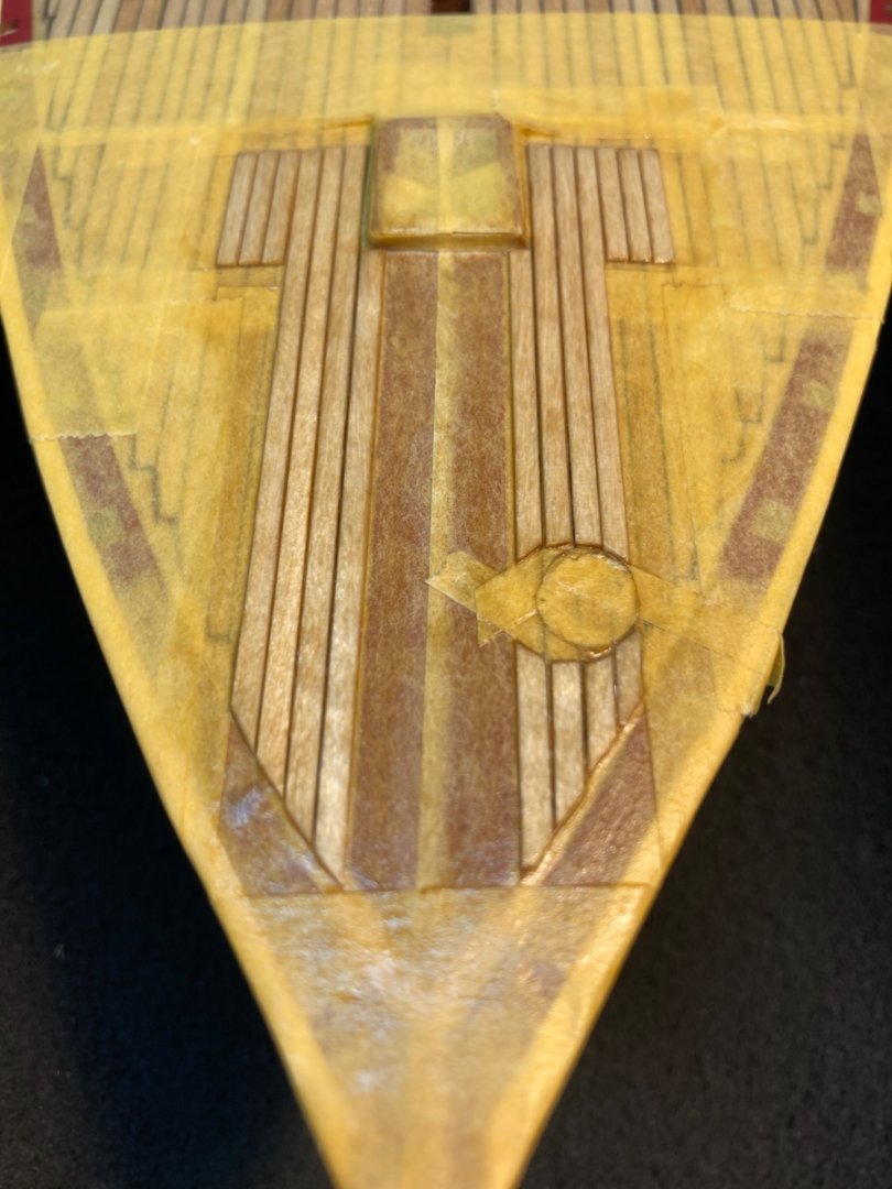
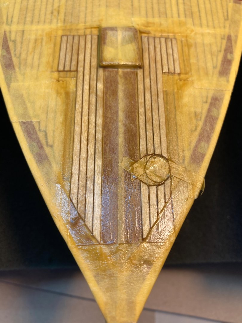
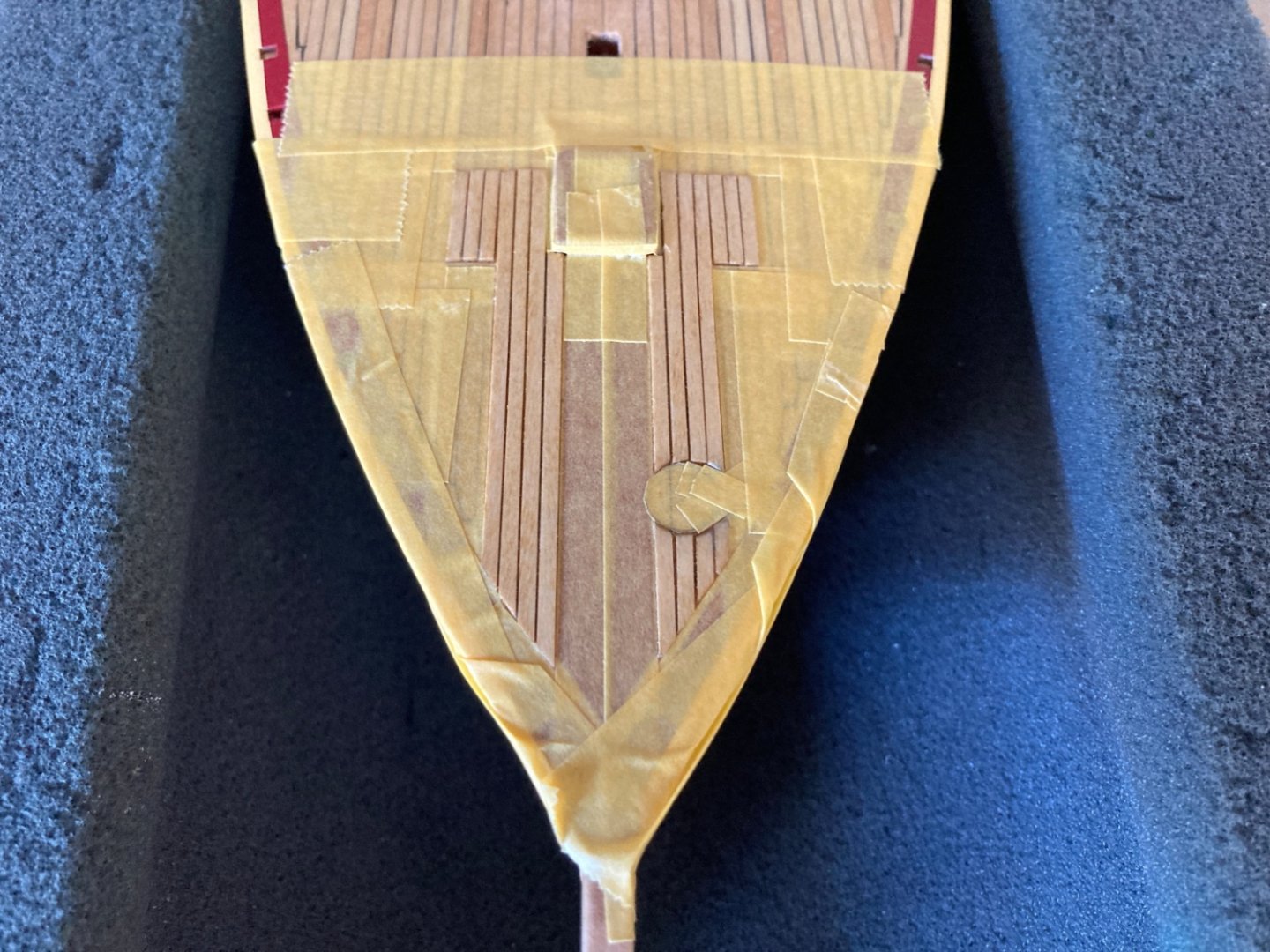
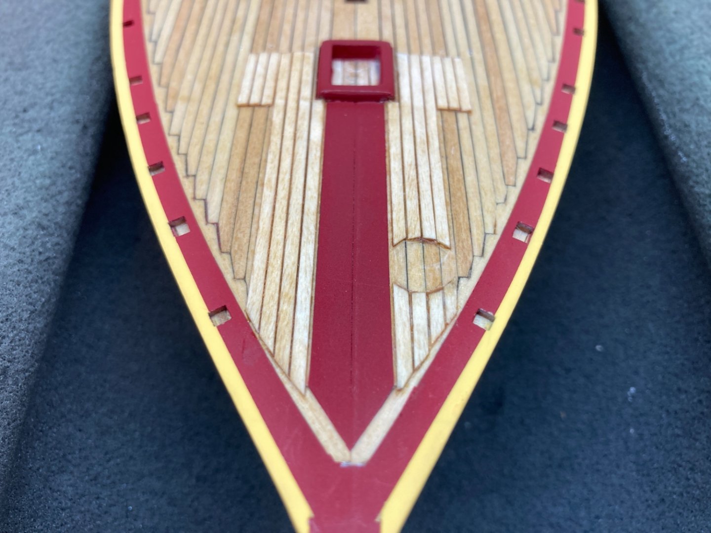
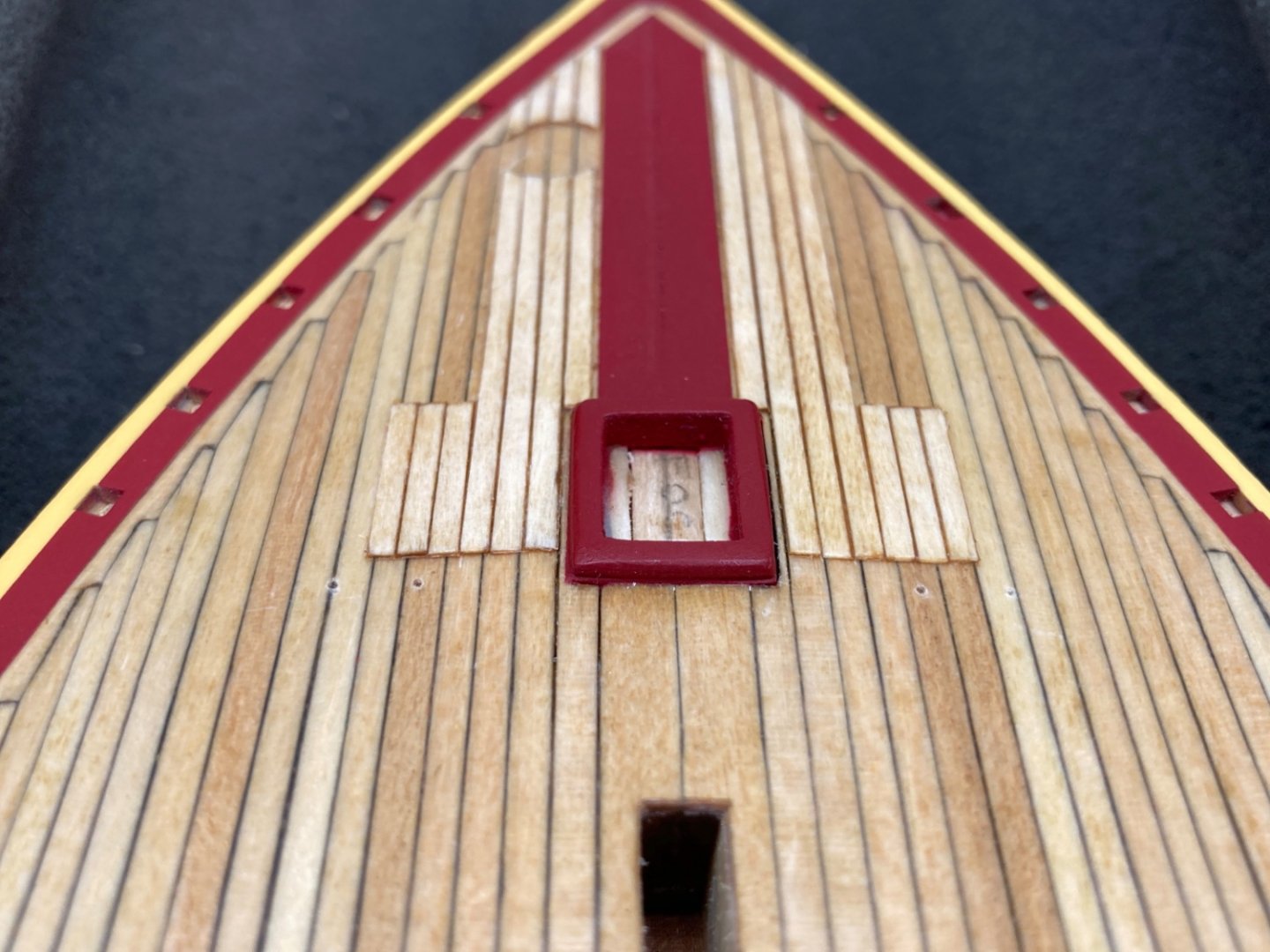
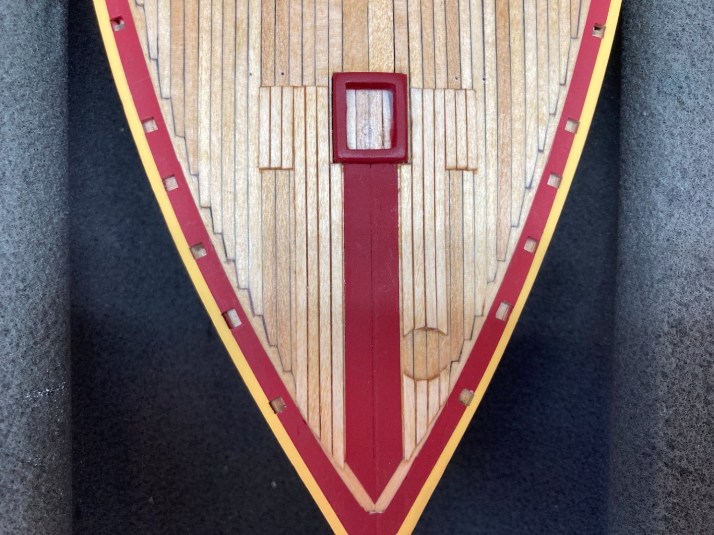
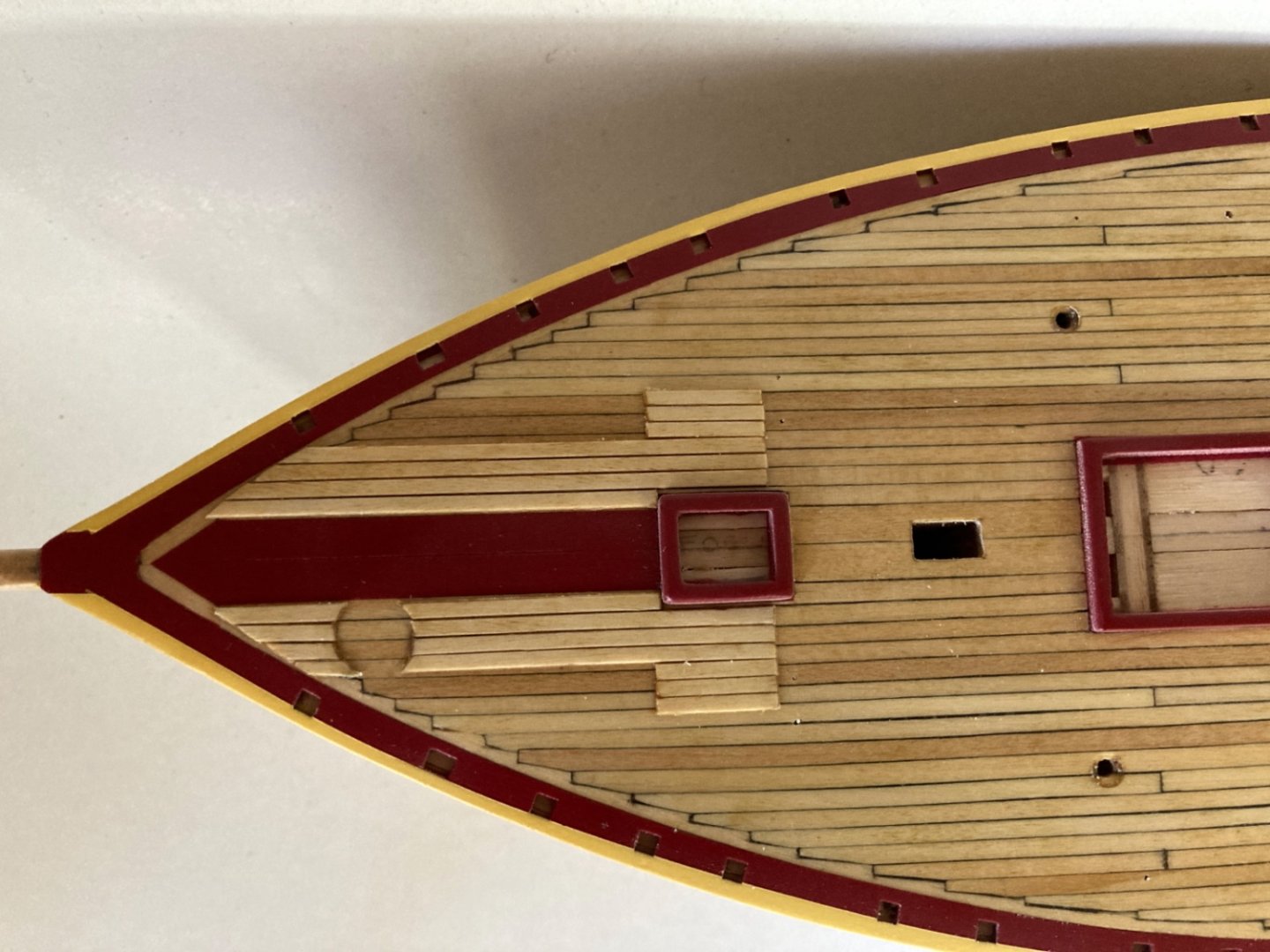
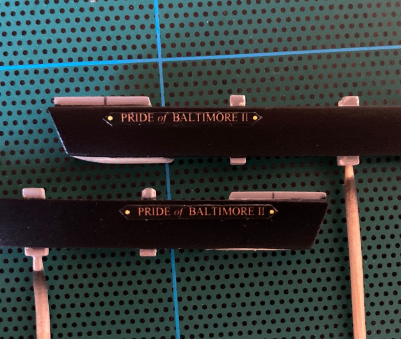
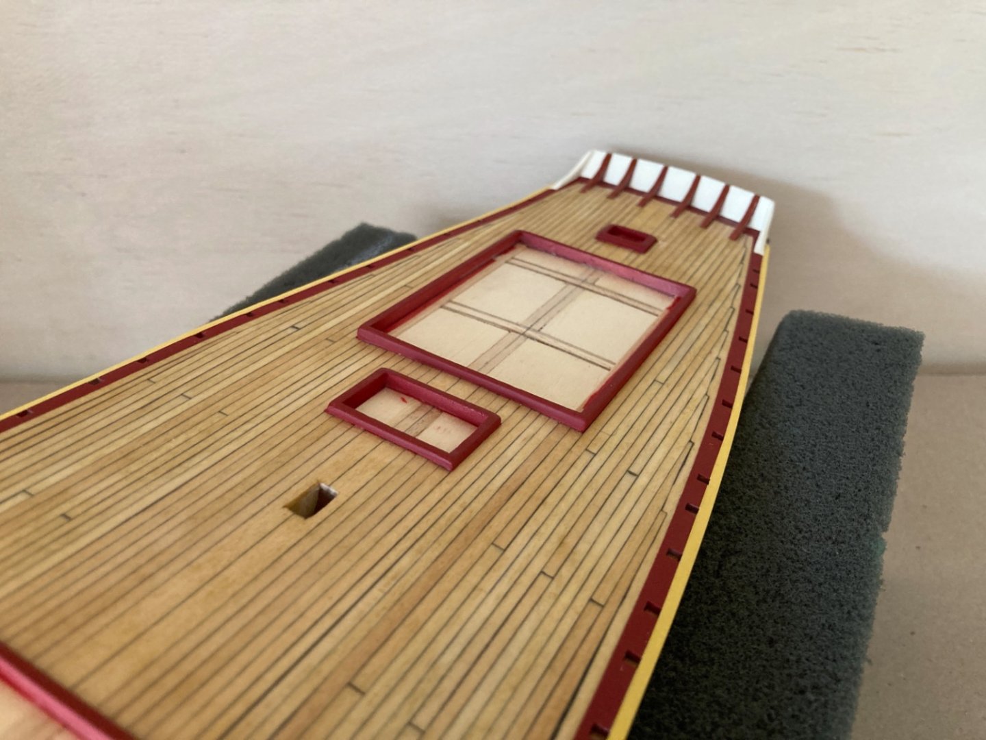
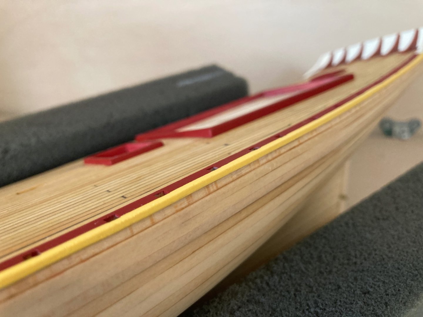
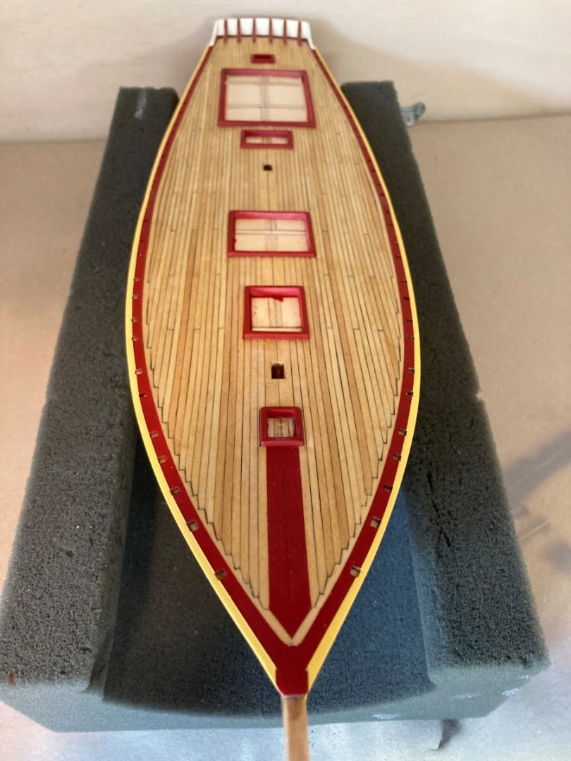
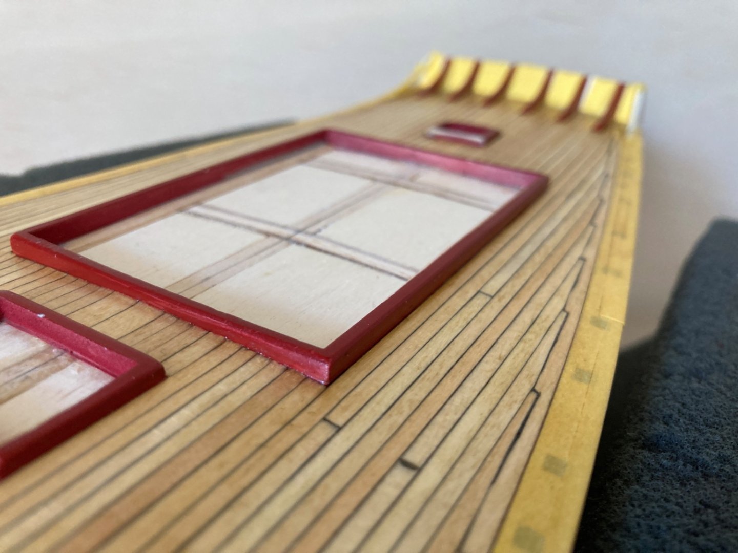
On the fore deck there was a small area of second planking. This was for to prevent the demage that maybe caused by anchor chains and ropes ! to the proper deck. This was last step to be done before the final the application of the clear coat to the deck. The planks here have a narrow space between them contrary to the already placed deck ones. There is also a round circular space at fore port area reserved for the steel hatch which will be built and placed later. The planks are cut to size and glued. After masking Sanding was done after the masking in order to prevent damage to deck. Photos after sanding. After Antique Pine stain application After the stain painted masks were removed, new masking was done for sanding sealer job. Masks were removed and the deck was ready for the final clear coat. Commercial clear matt varnish was used as the final coat on the deck. The varnish was diluted by commercial lacquer thinner with 1:1 ratio and airbrushed by Paasche Single Action Bottom Feed airbrush with a pressure around 1 Bar. Here are the photos after clear matt coat application. Following the deck, final coat job was done on the bulwarks after the bulwark structures (excluding the cleats and eyebolts with rings which were done much more later) were glued in places and the holes connecting the cavil holes to mooring chock holes, through the wood blocks between them, were opened. Also the lettering of the ship's name at the bow on both sides were glued too. Those letterings were prepared before. Here is how I done them. The lettering on the real ship is made of plate attached to the bulwarks. The lettering for the model was prepared in Word program and later printed on to 300 grams photo paper which was thick enough to simulate the thickness of the plate on the real ship. The white edges of the lettering was darkened by a fine tip black marker pen. The photos of the bulwarks after matt clear coat.


- 114 replies
-
- 3
-
-
- Pride of Baltimore II
- Model Shipways
- (and 1 more)
-
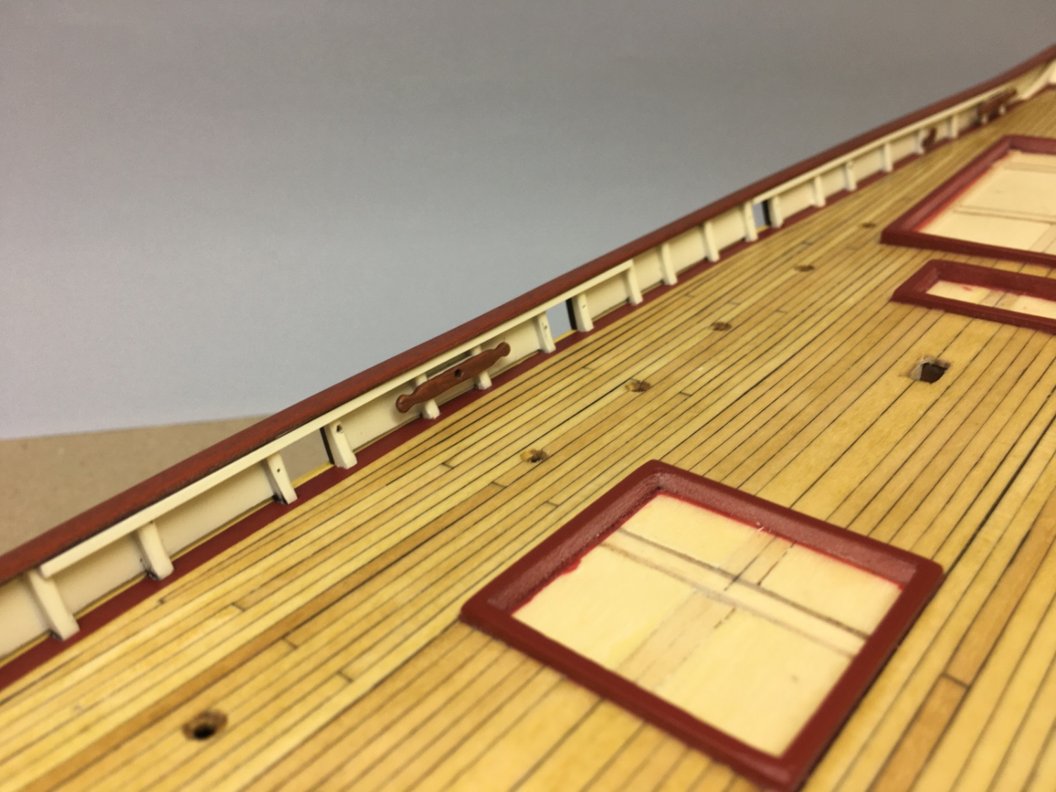
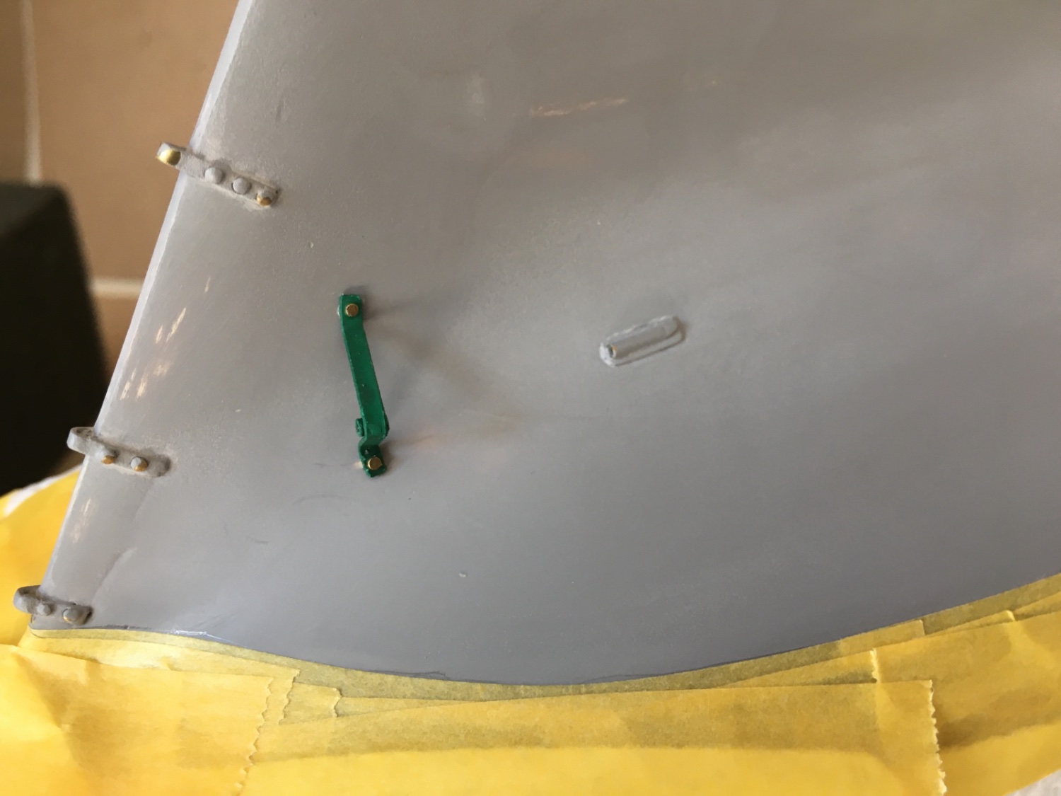
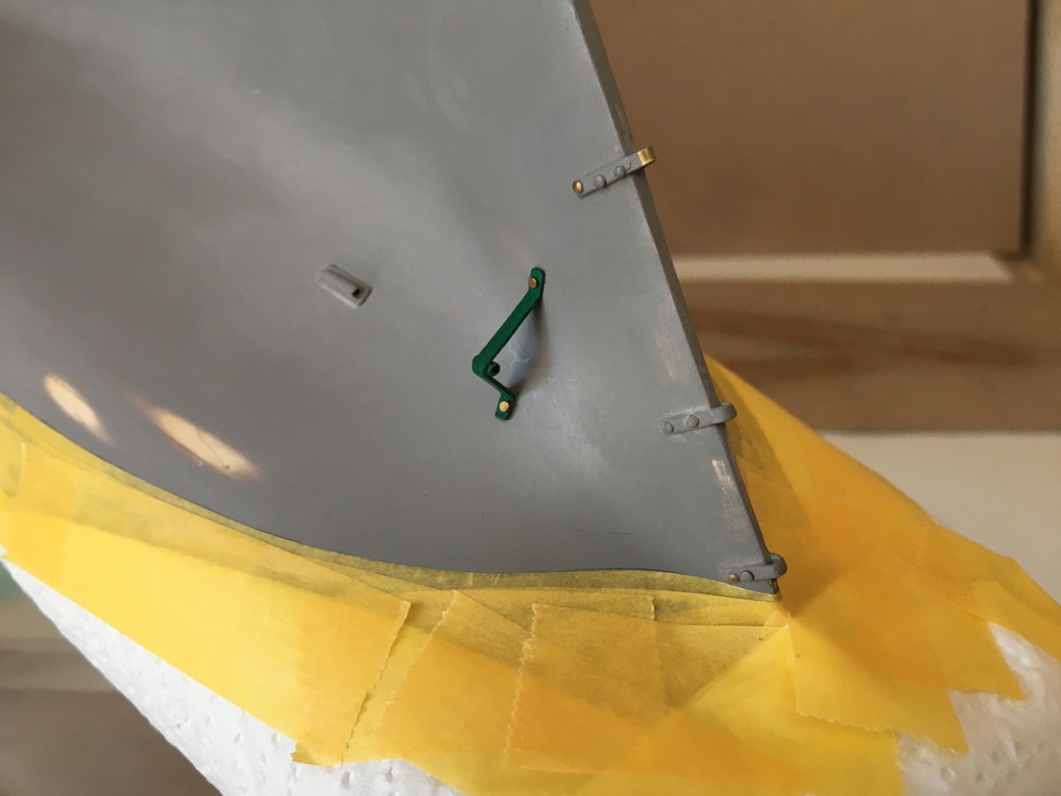
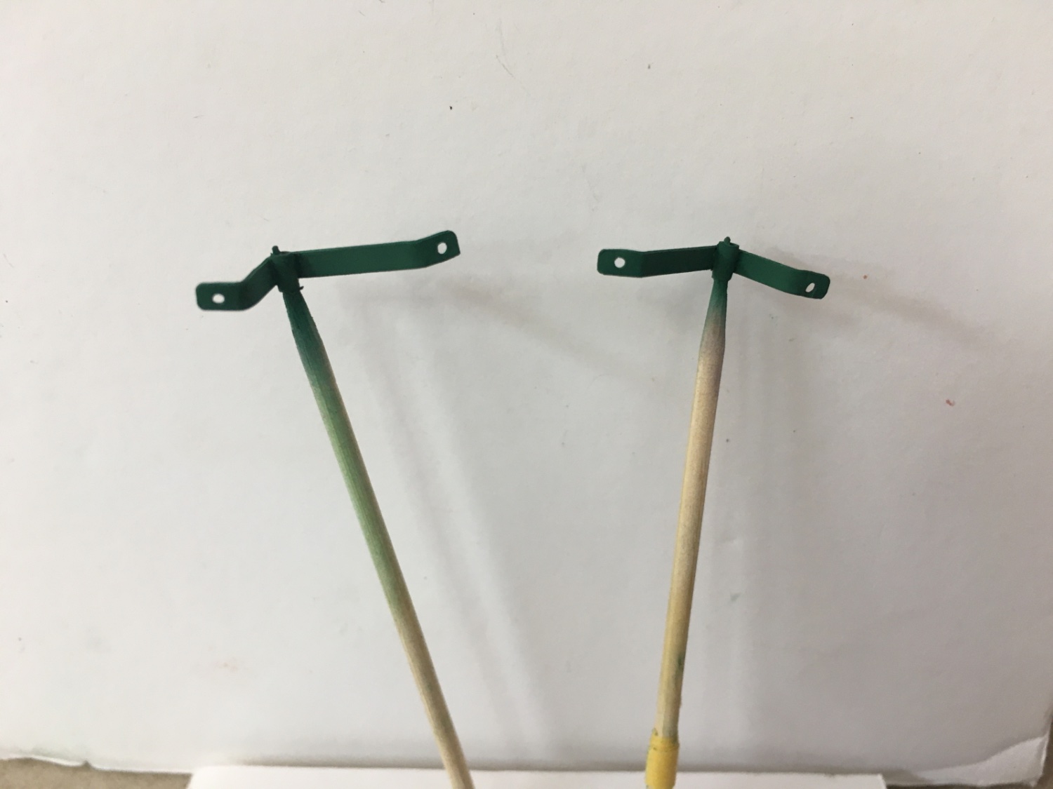
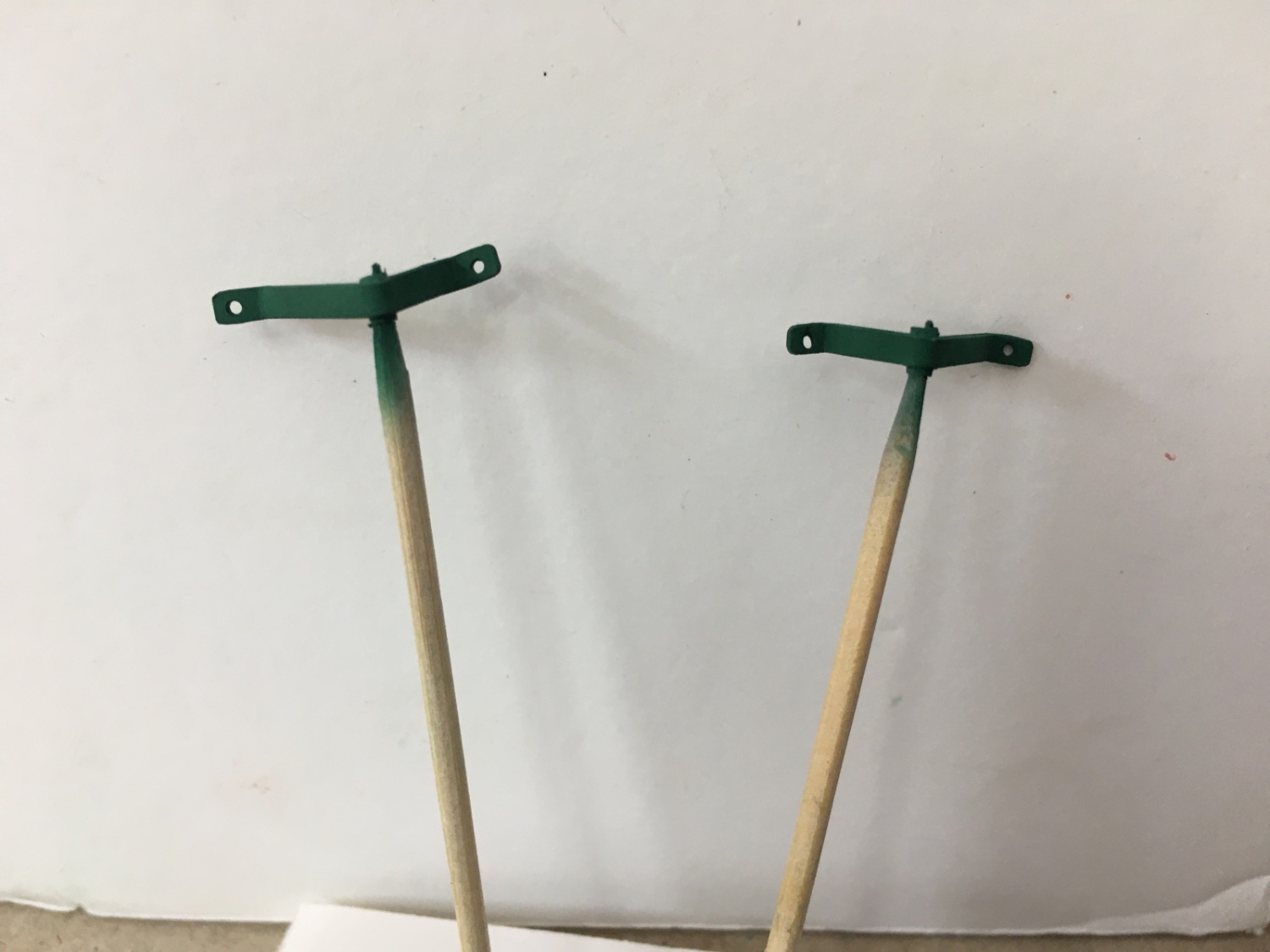
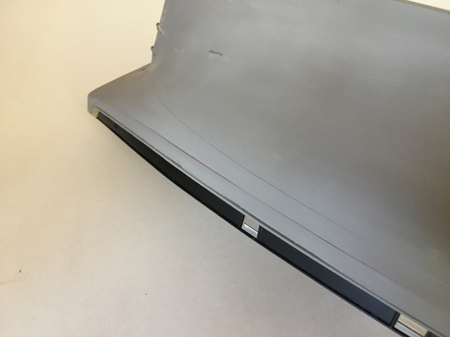
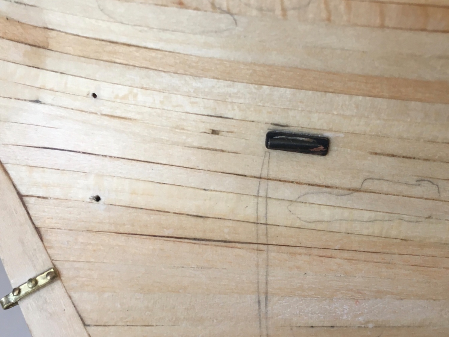
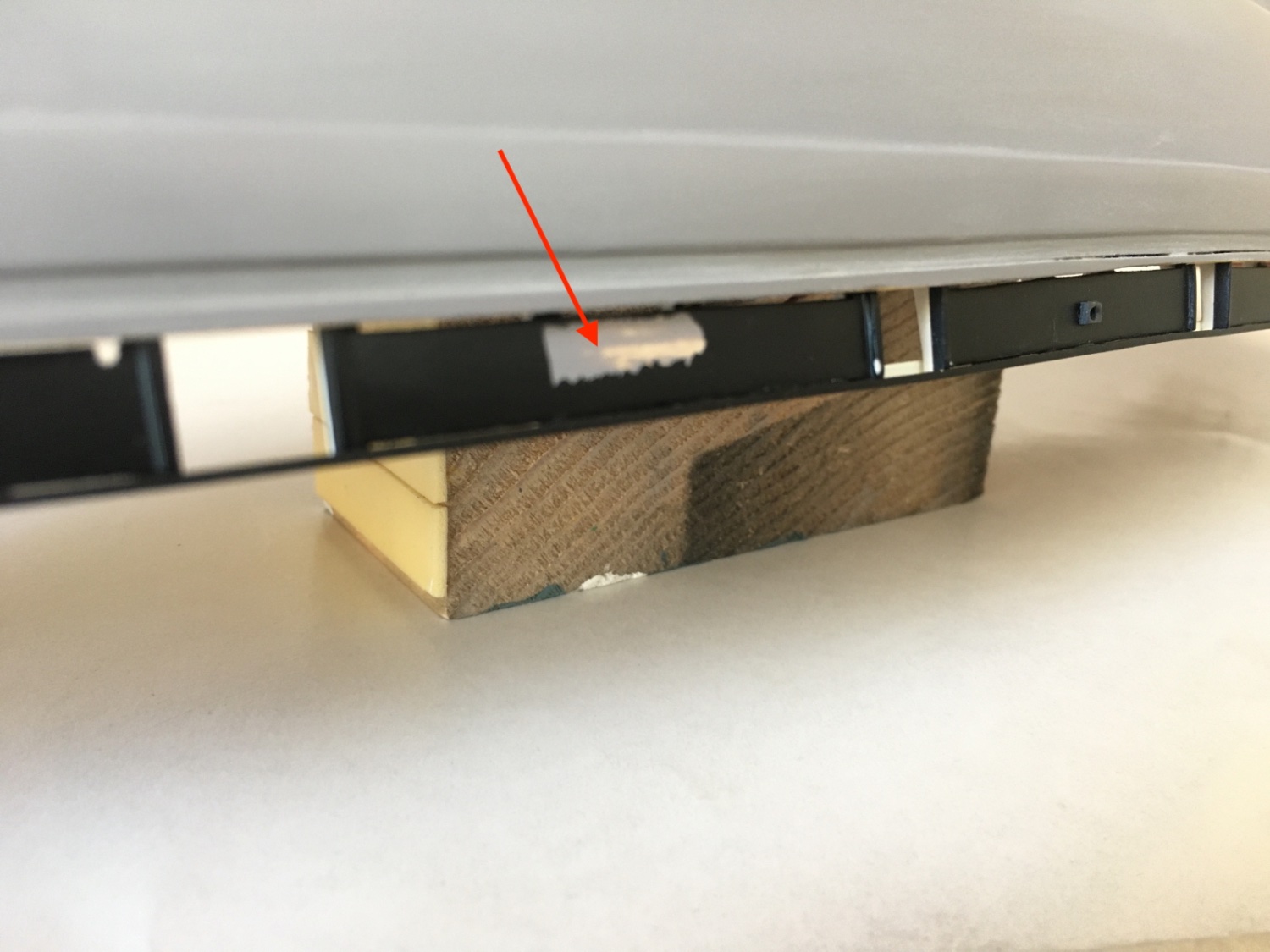
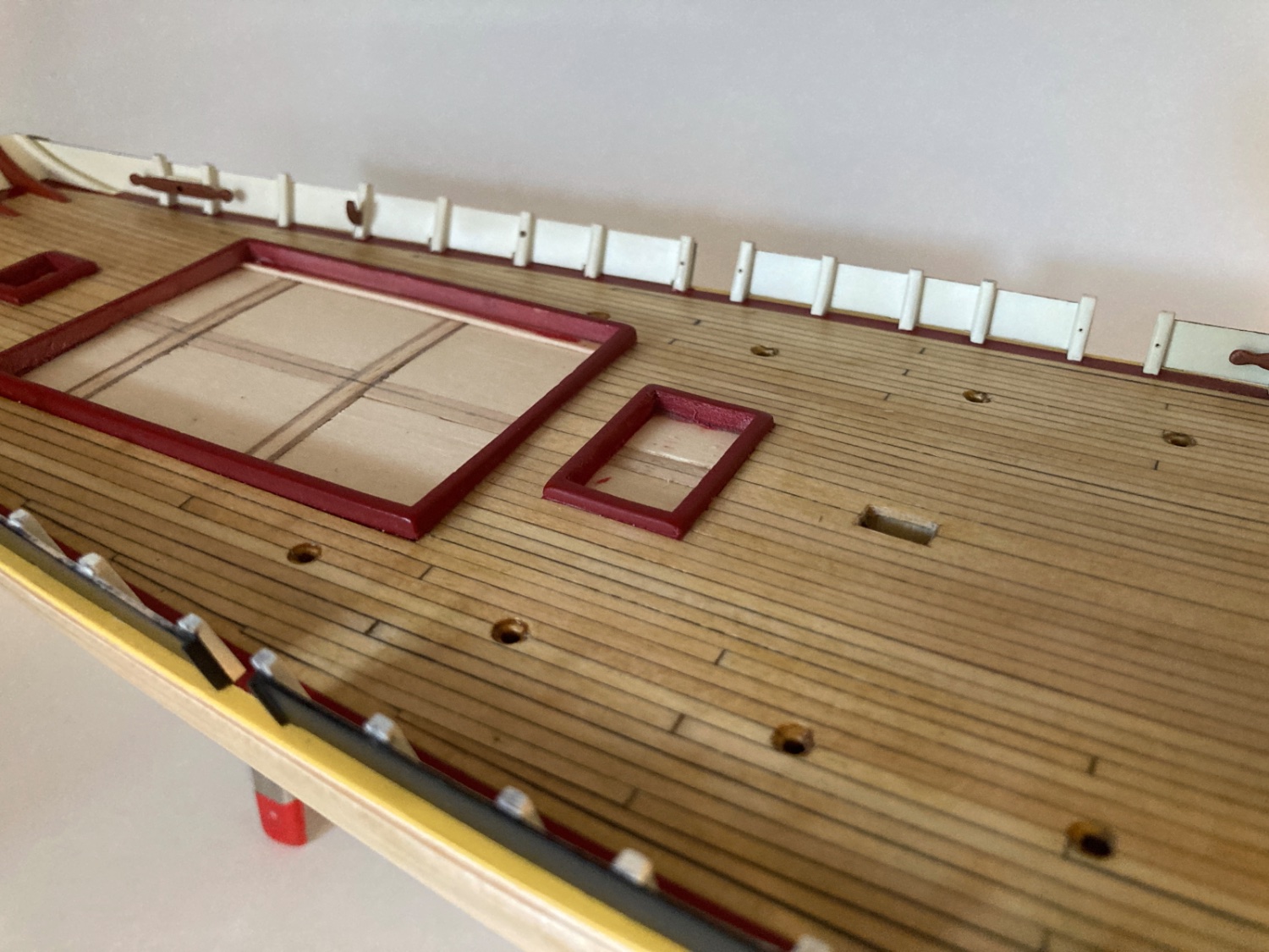
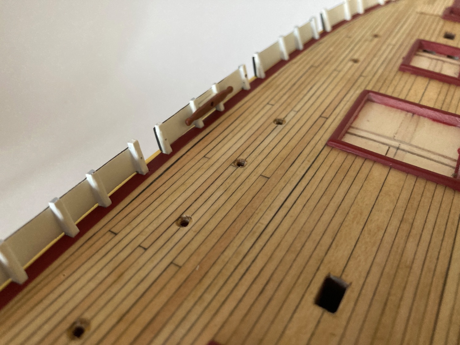
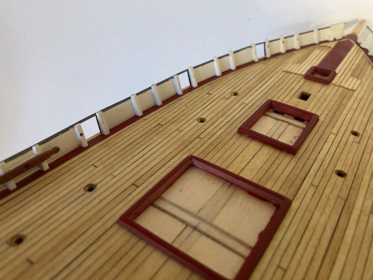
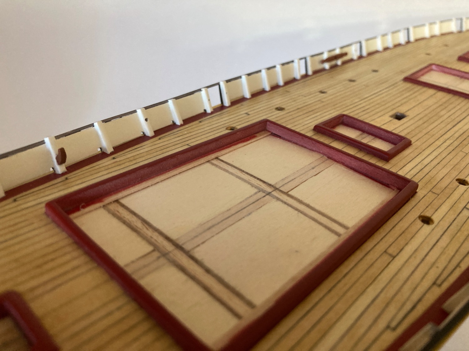
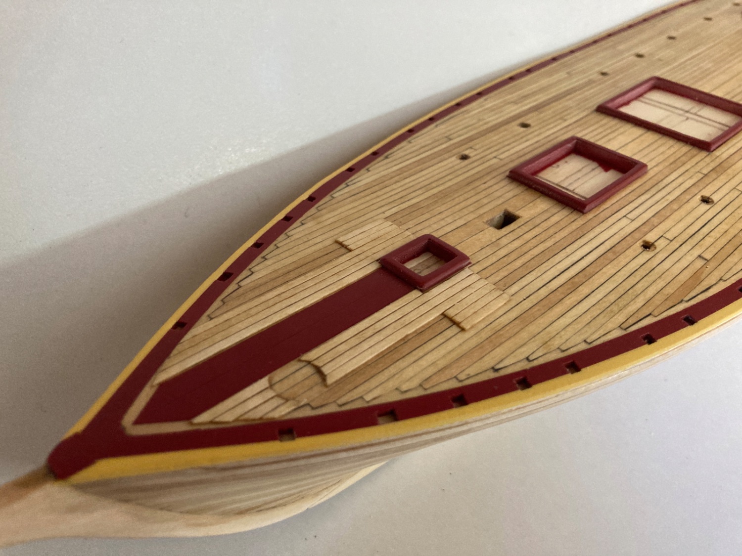
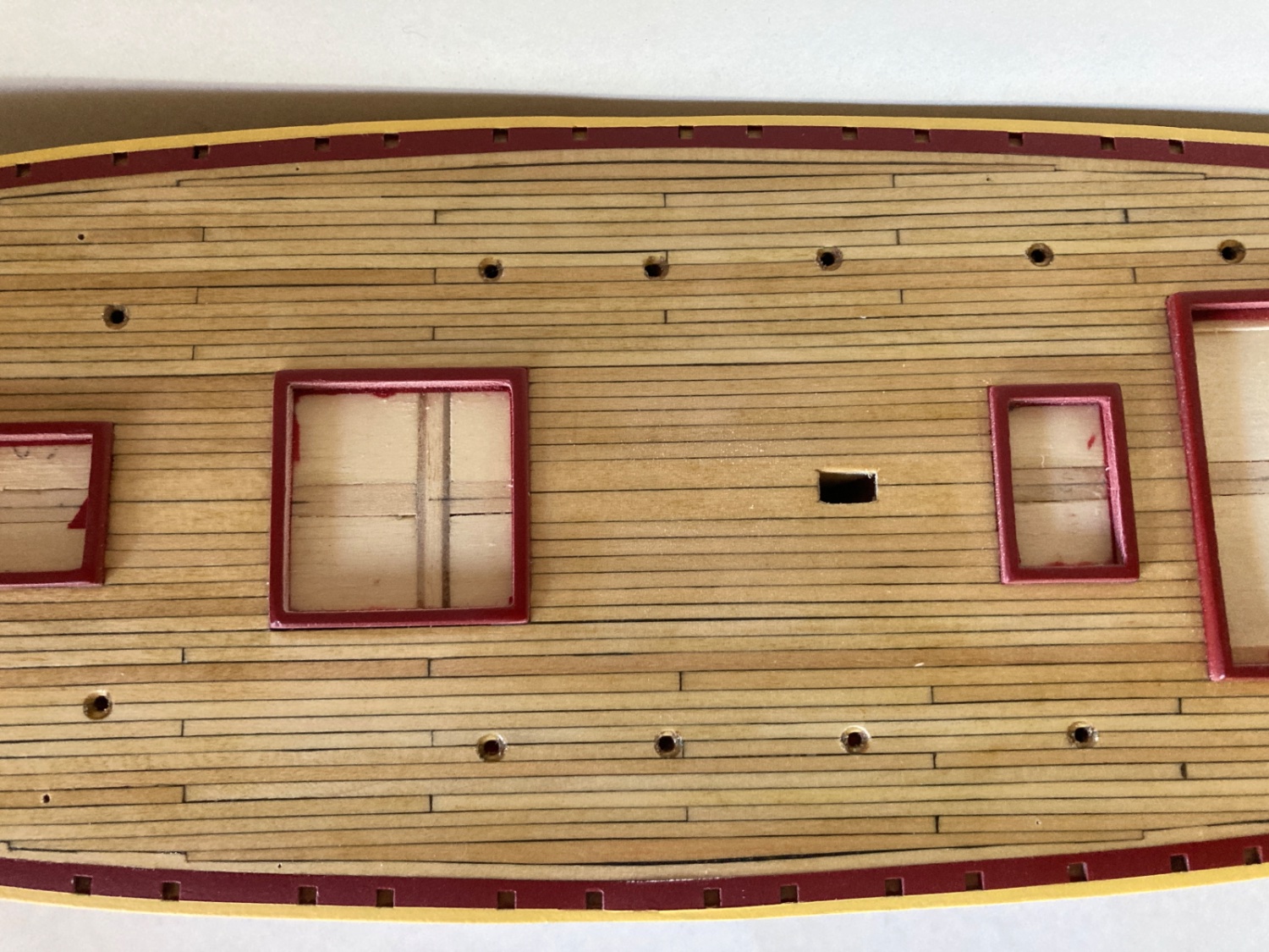
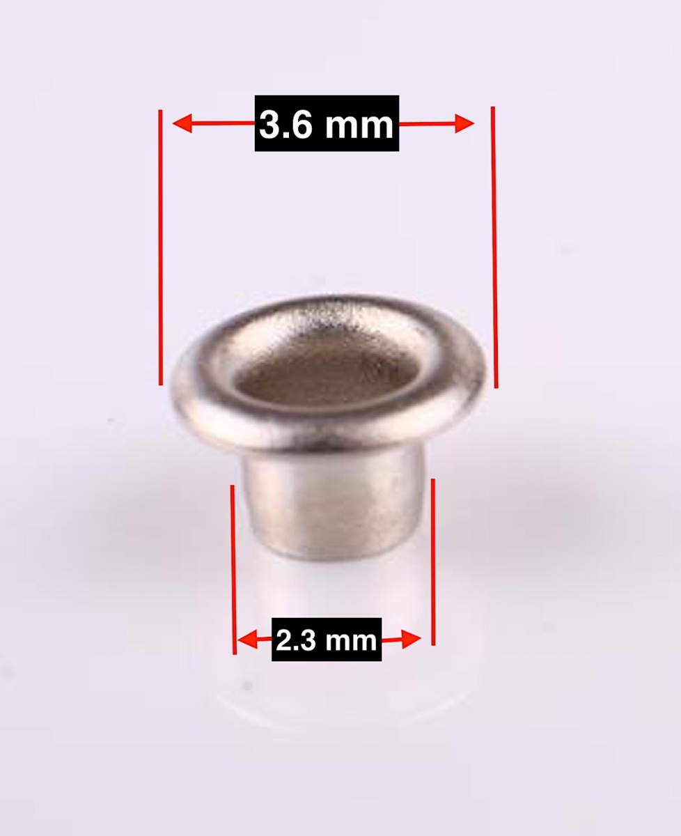
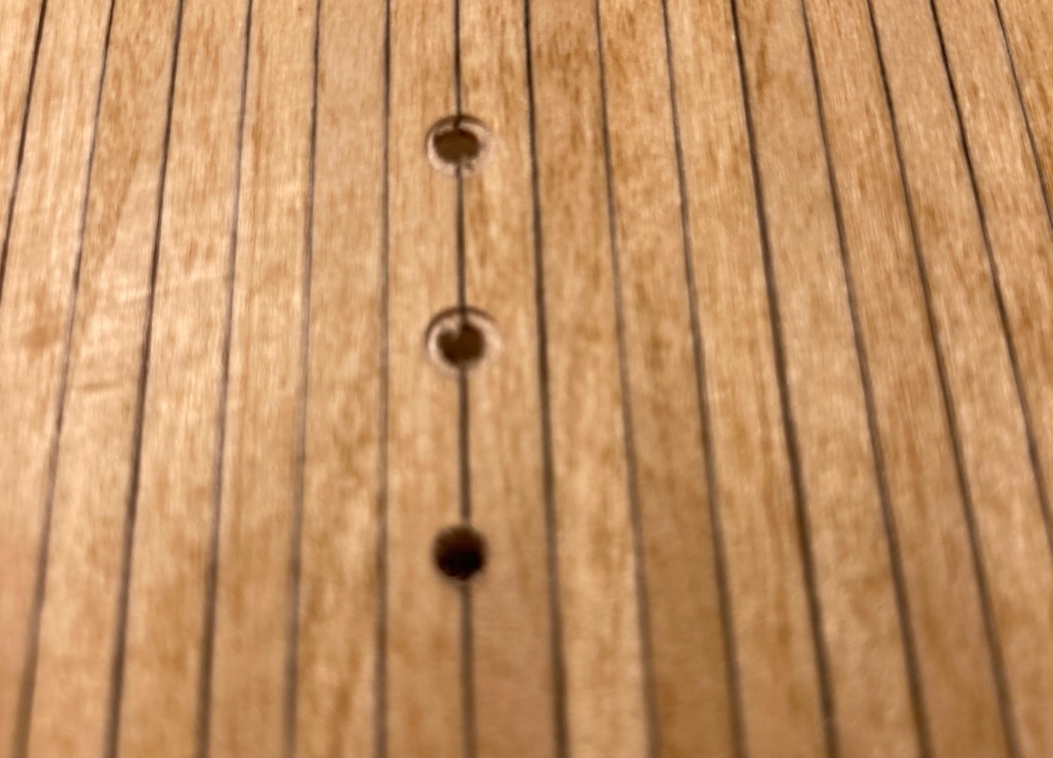
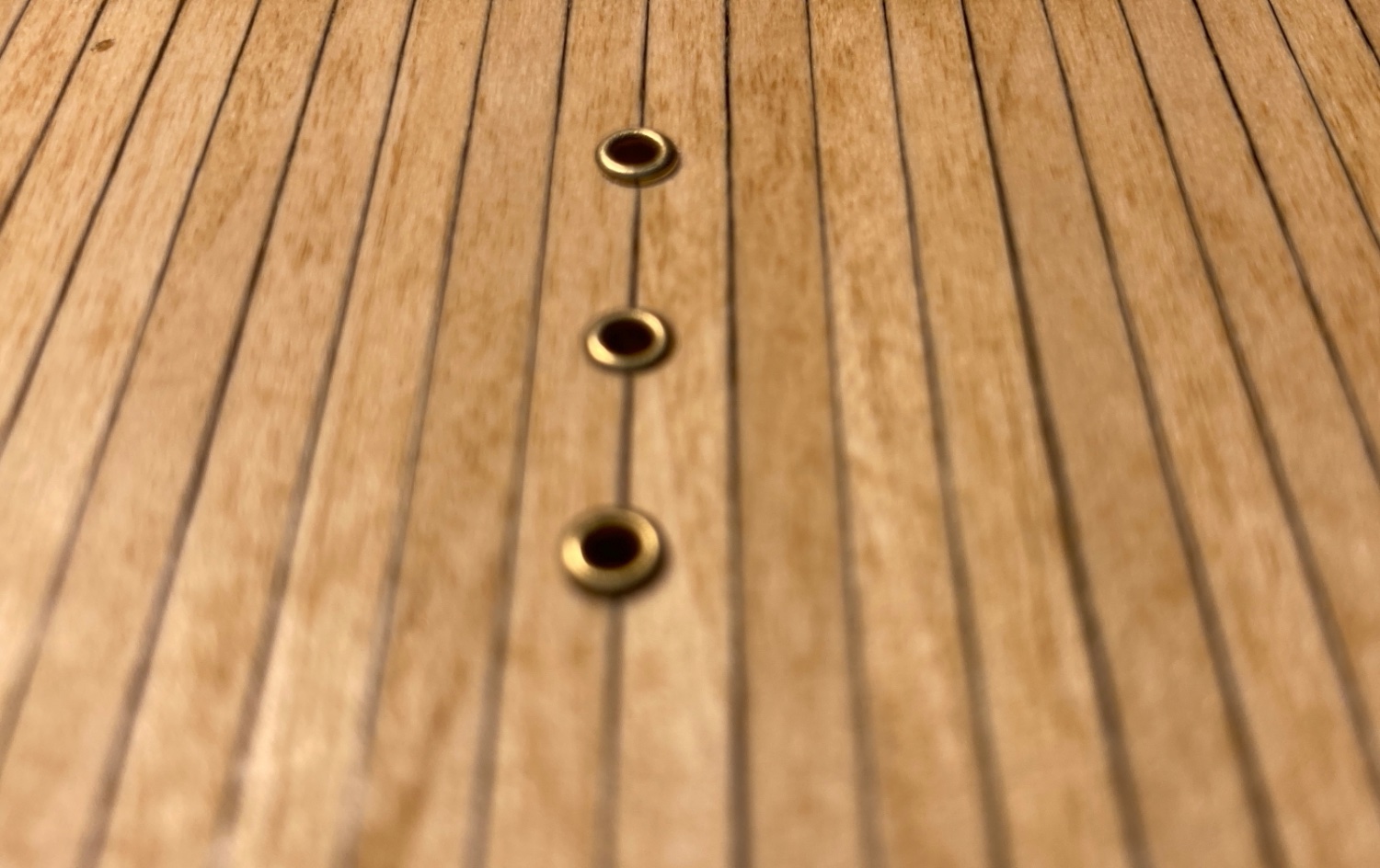
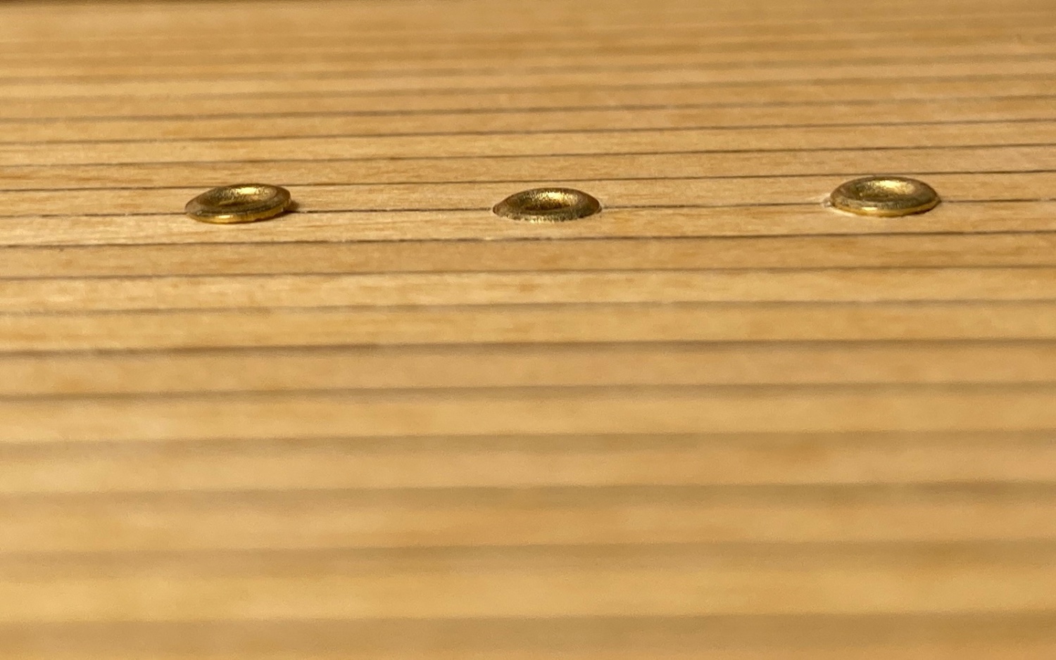
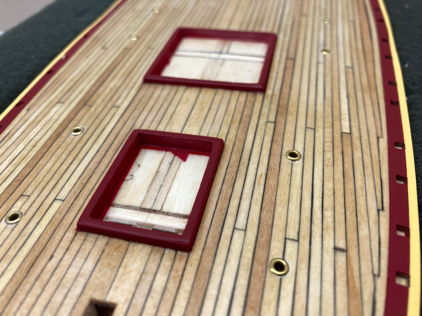
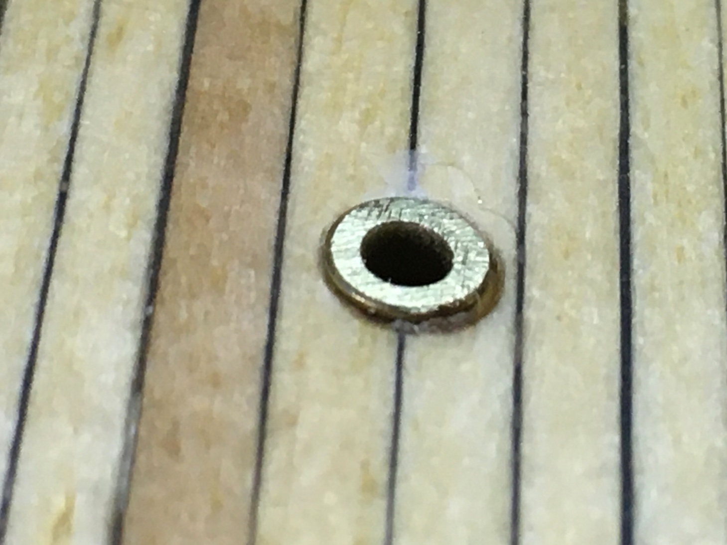
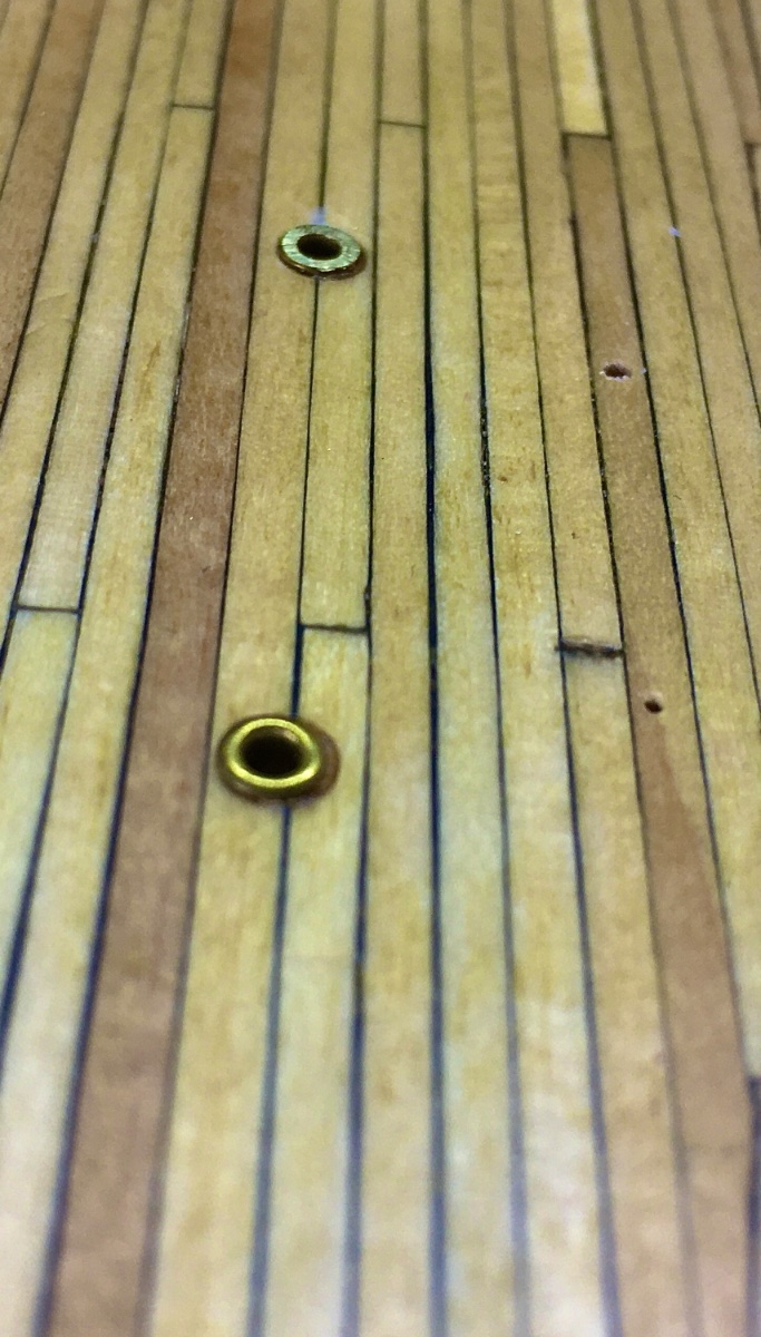
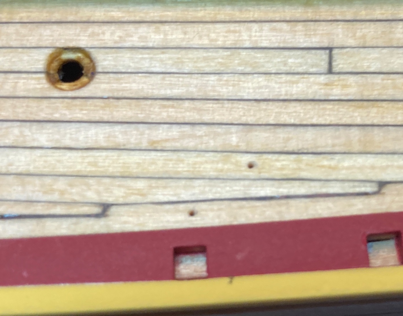
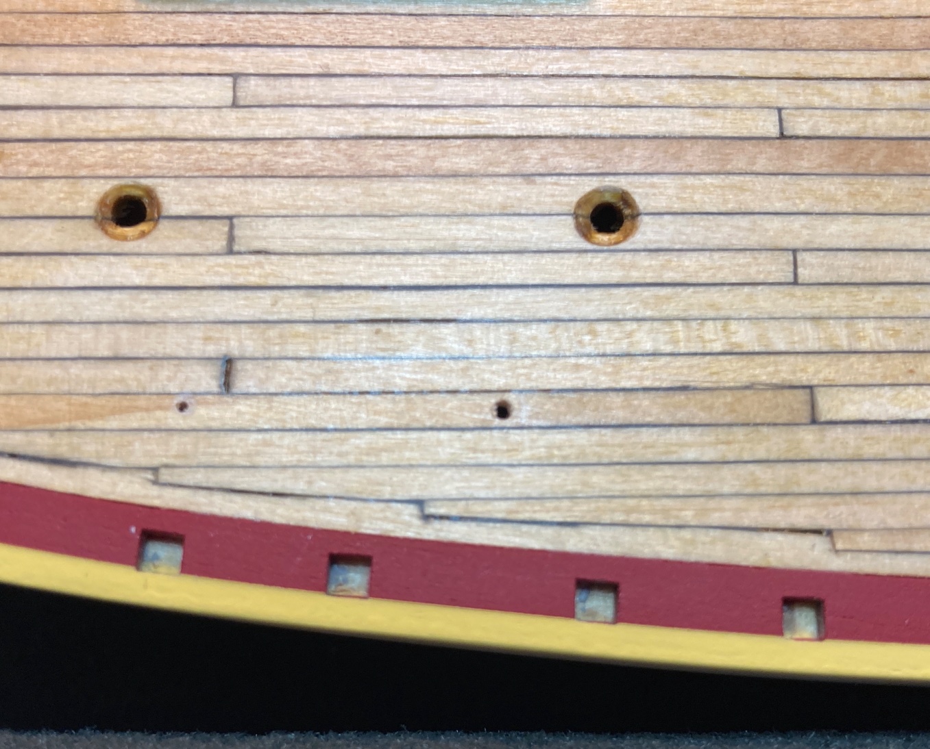
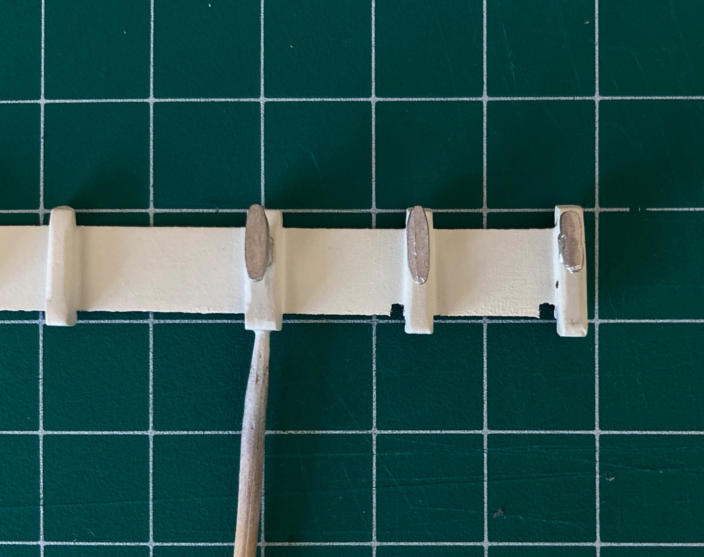
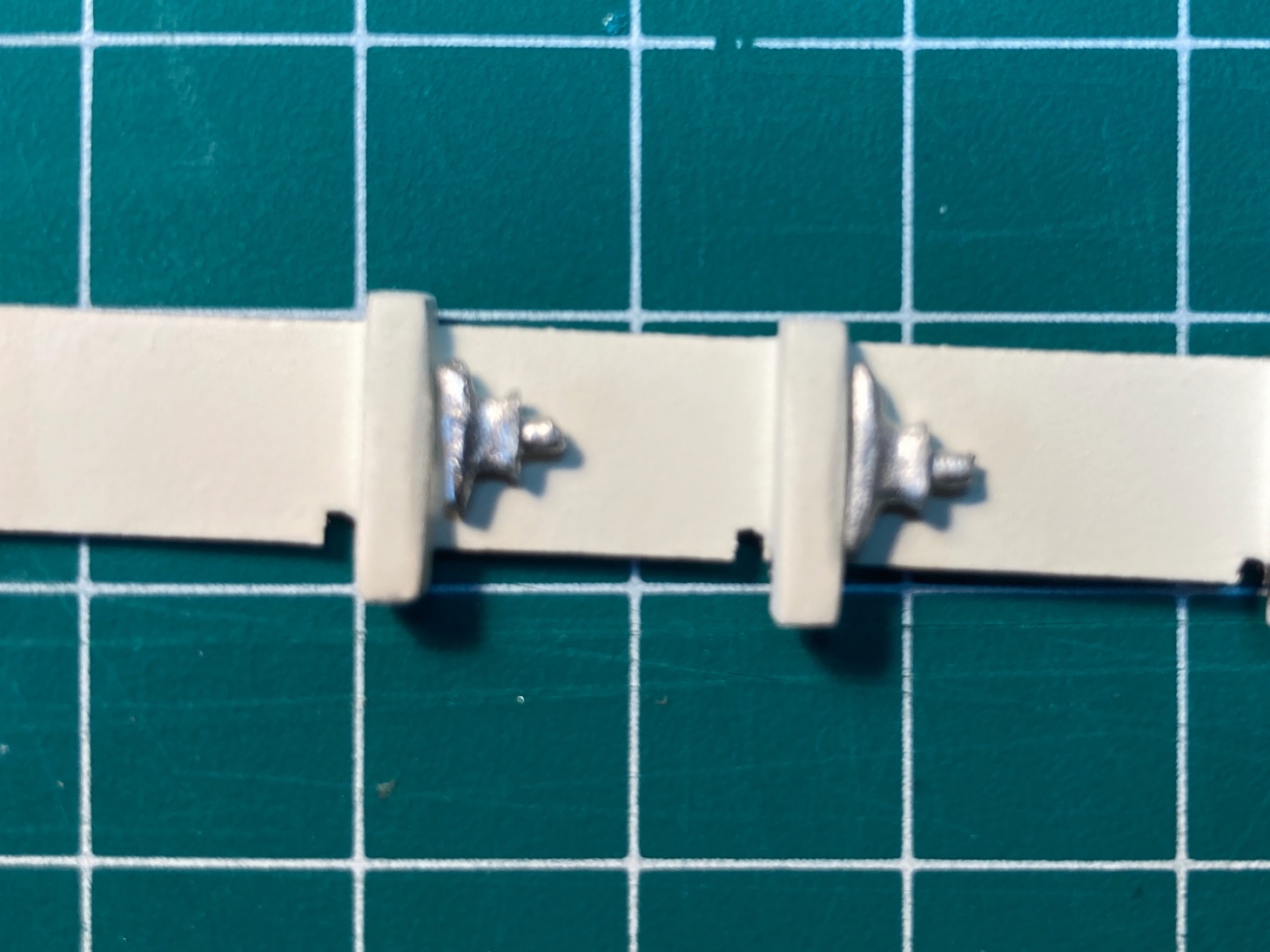
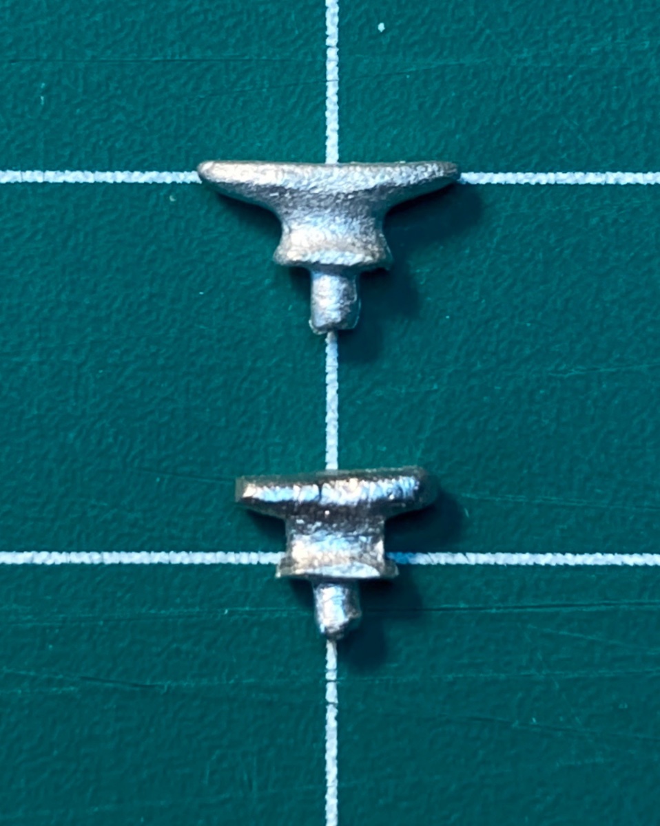
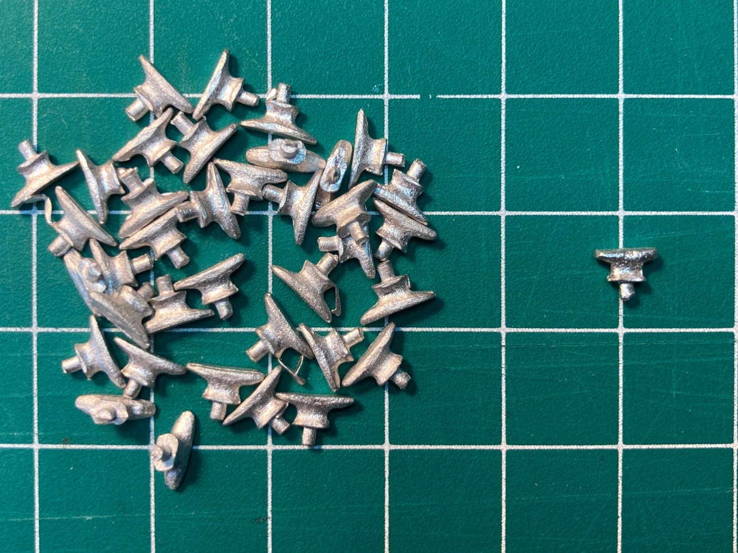
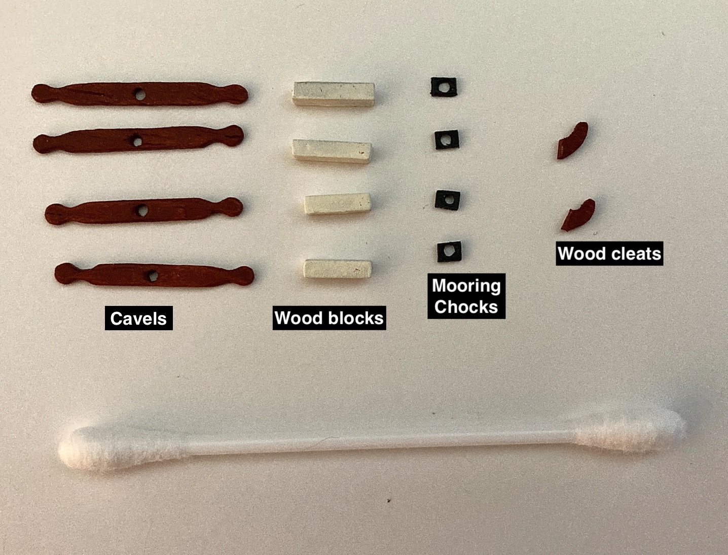
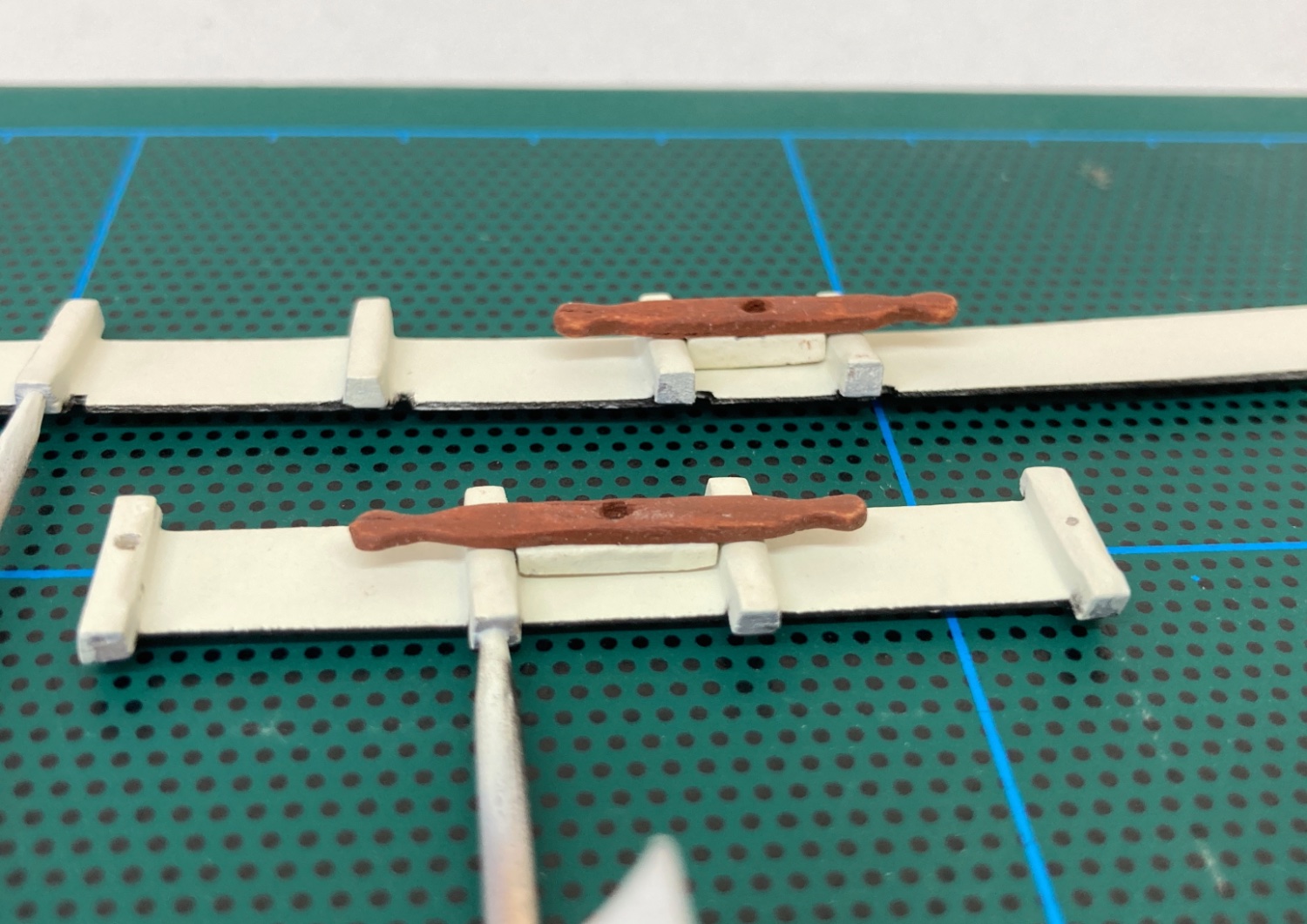
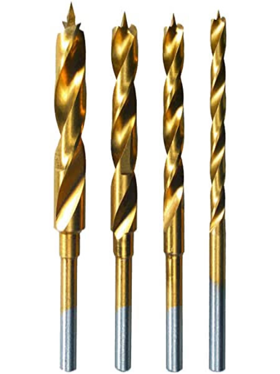
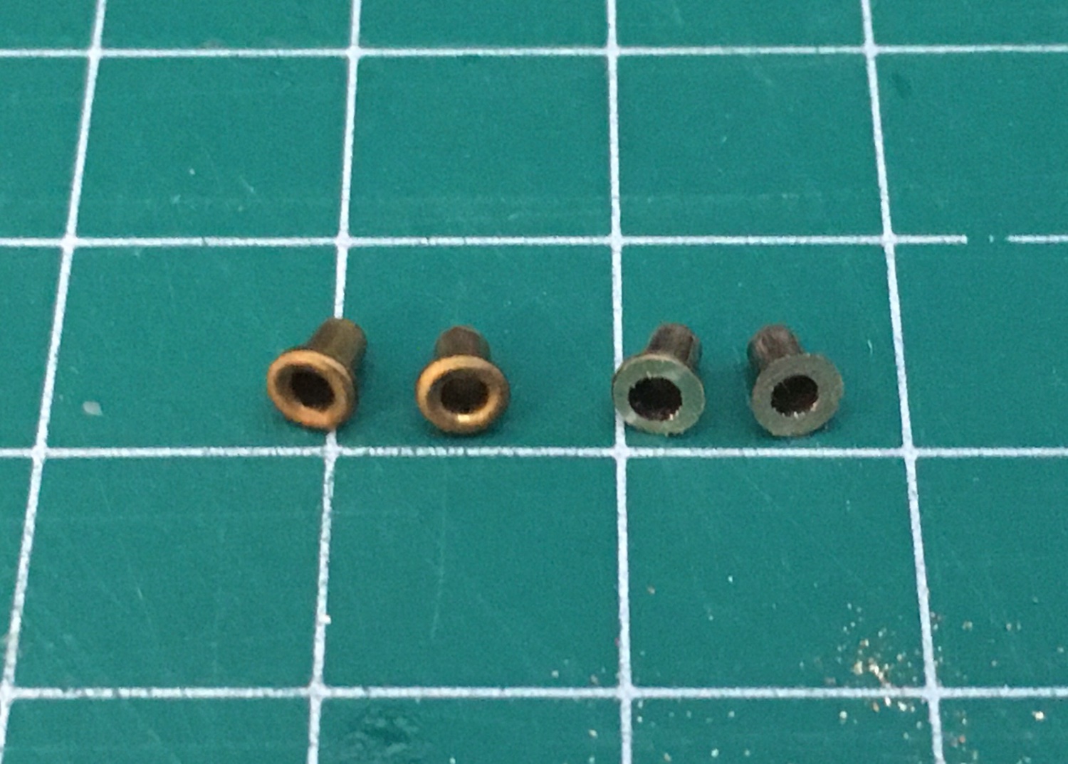
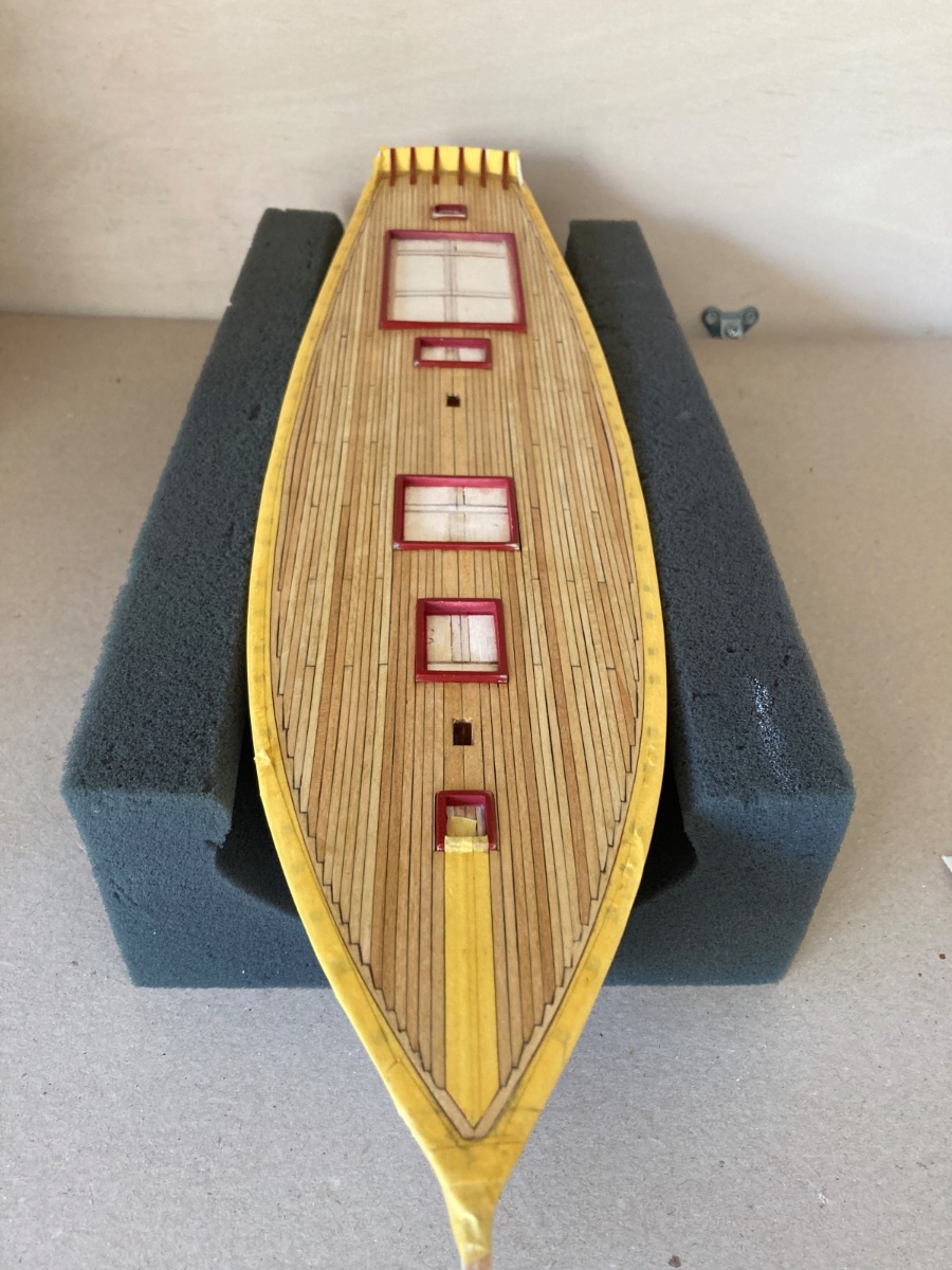
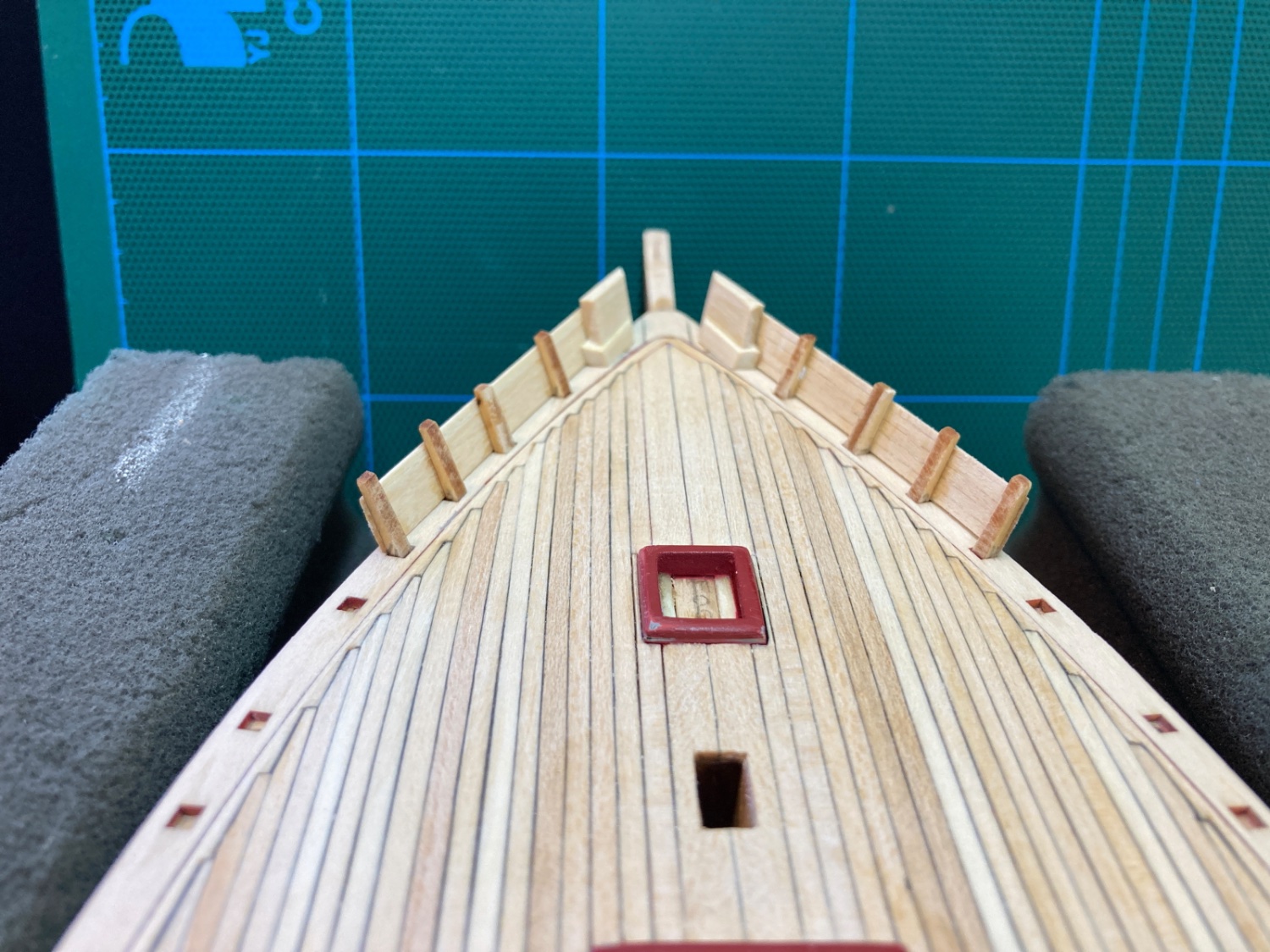
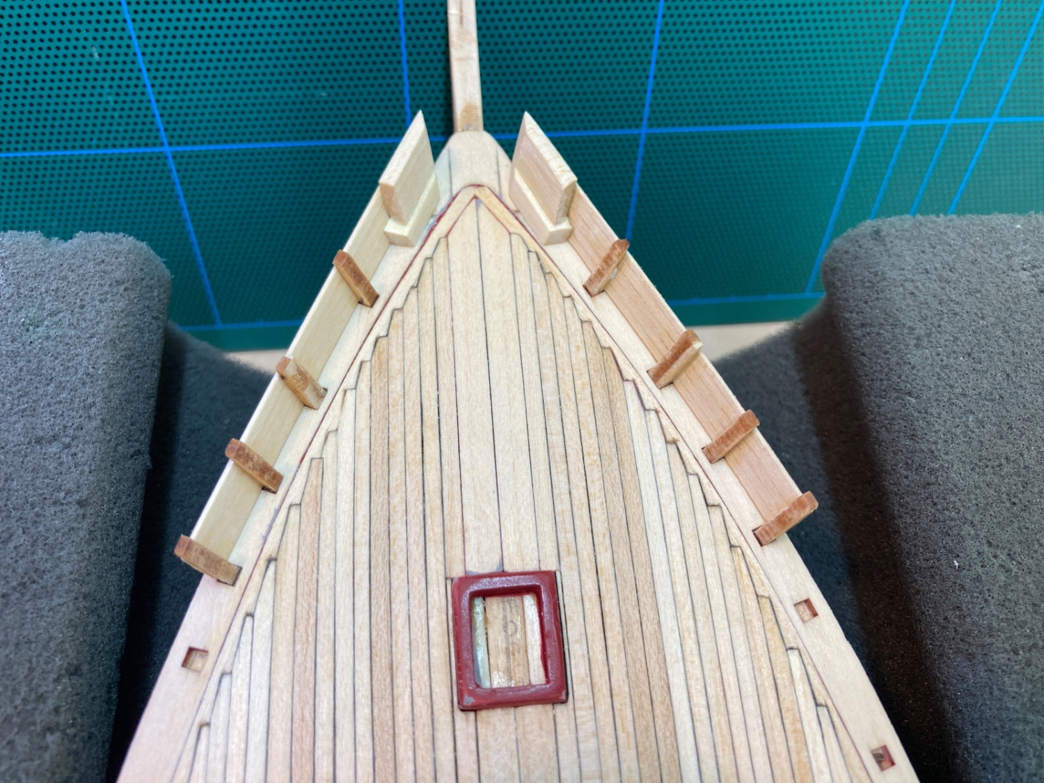
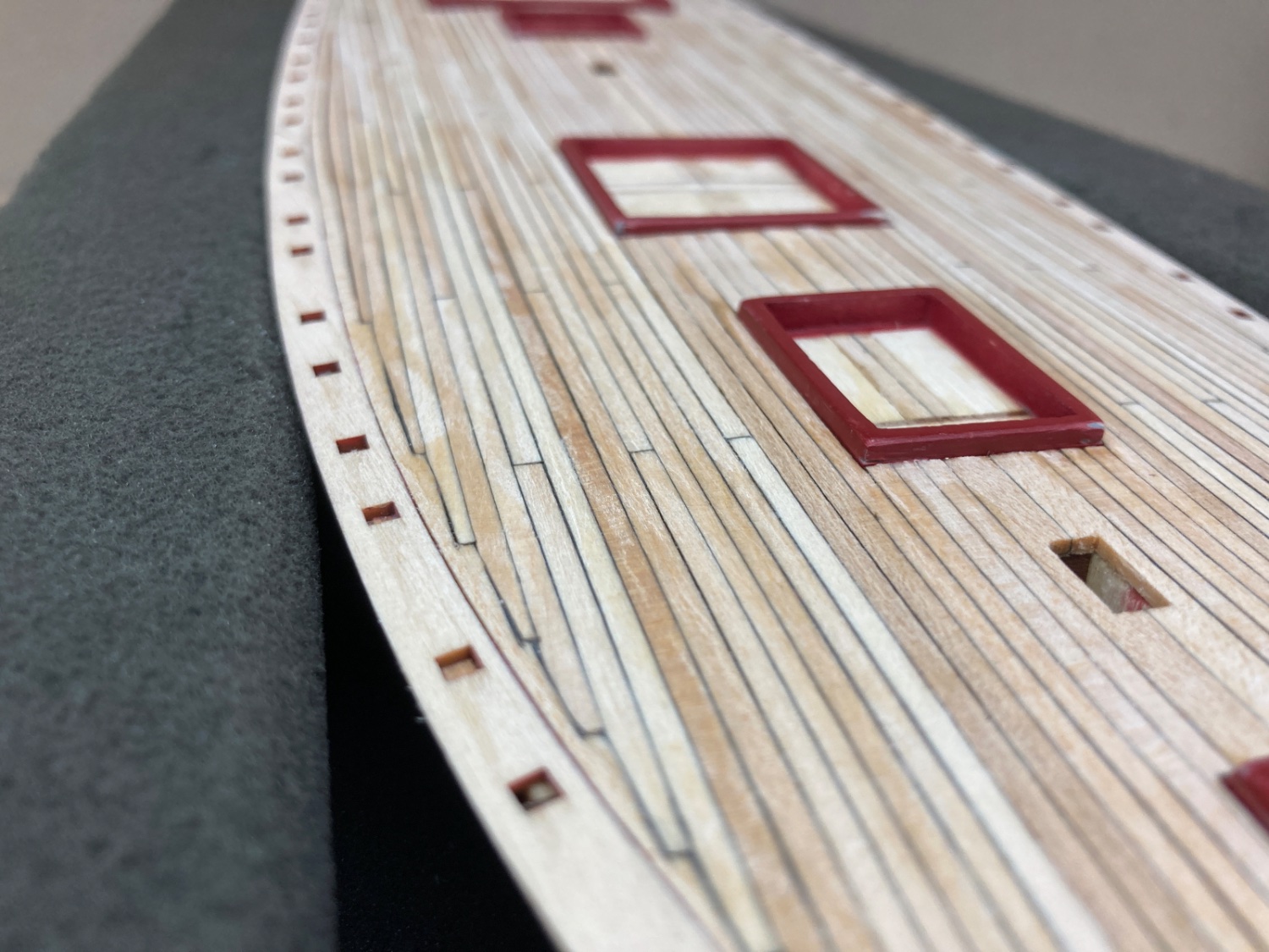
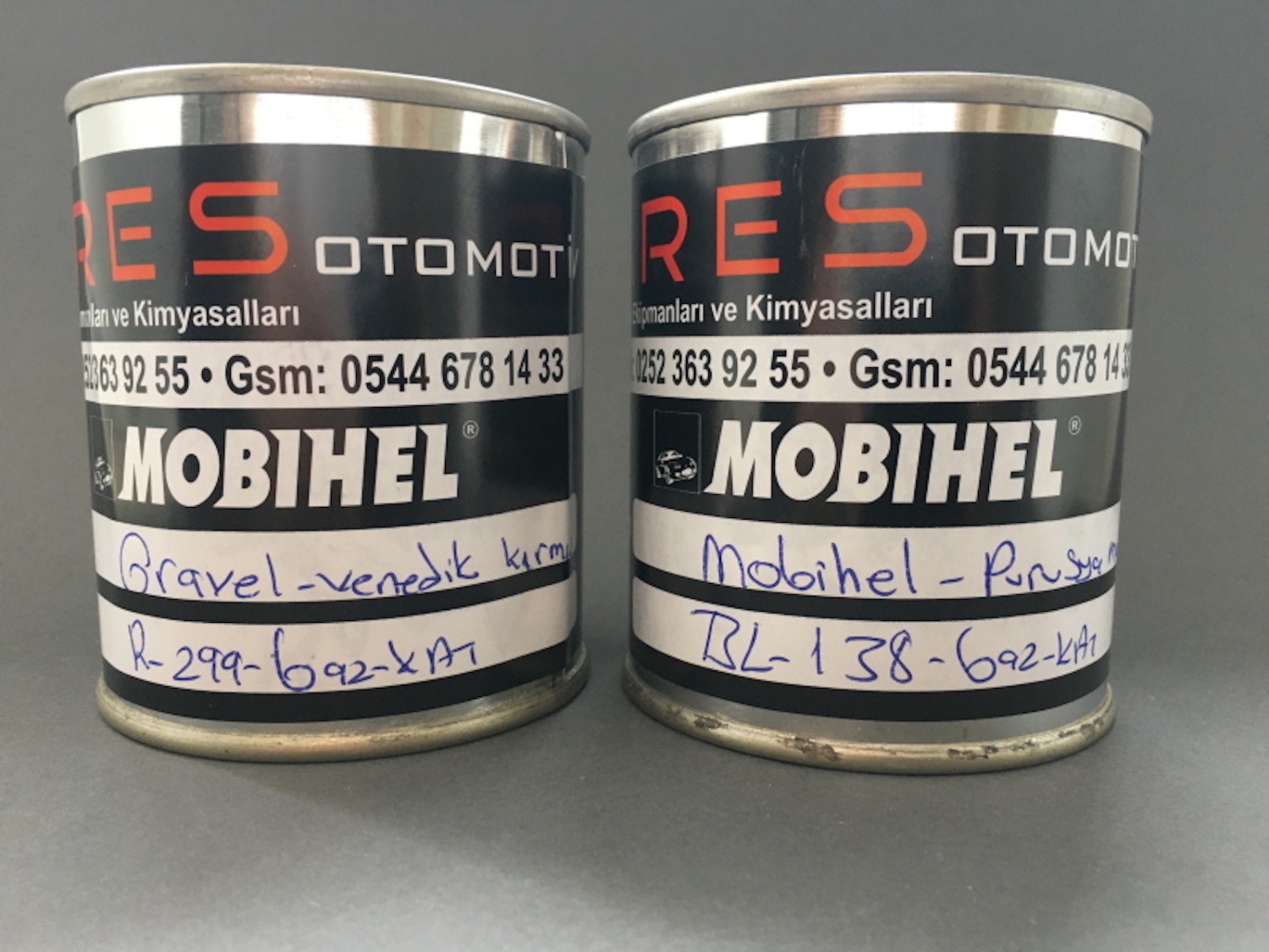
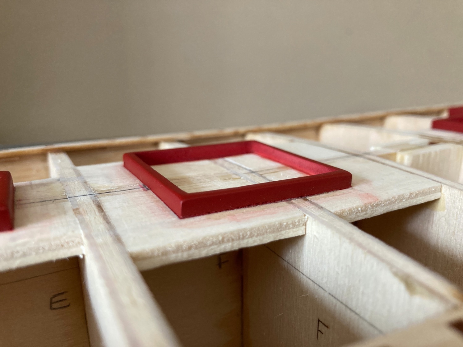
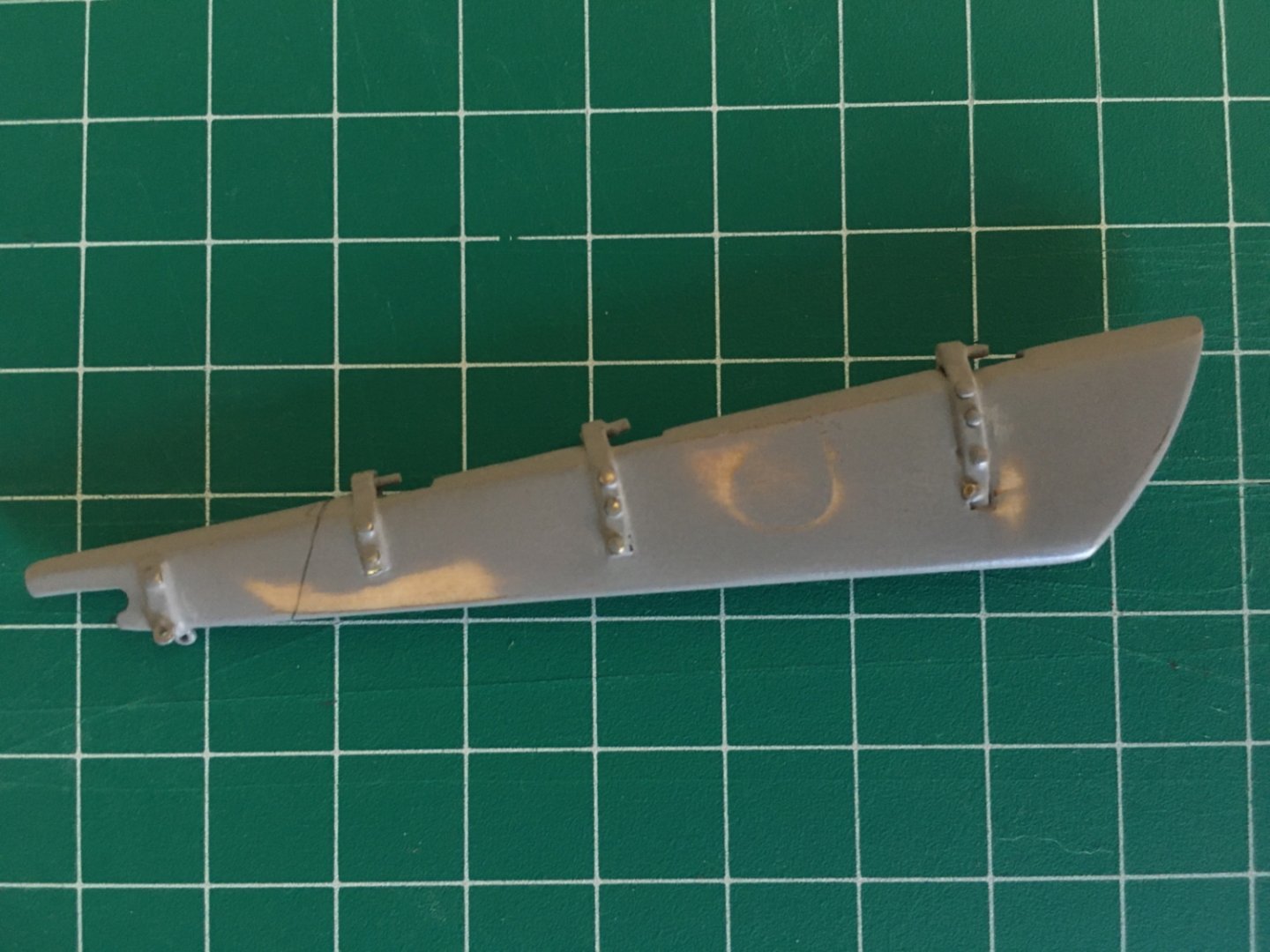
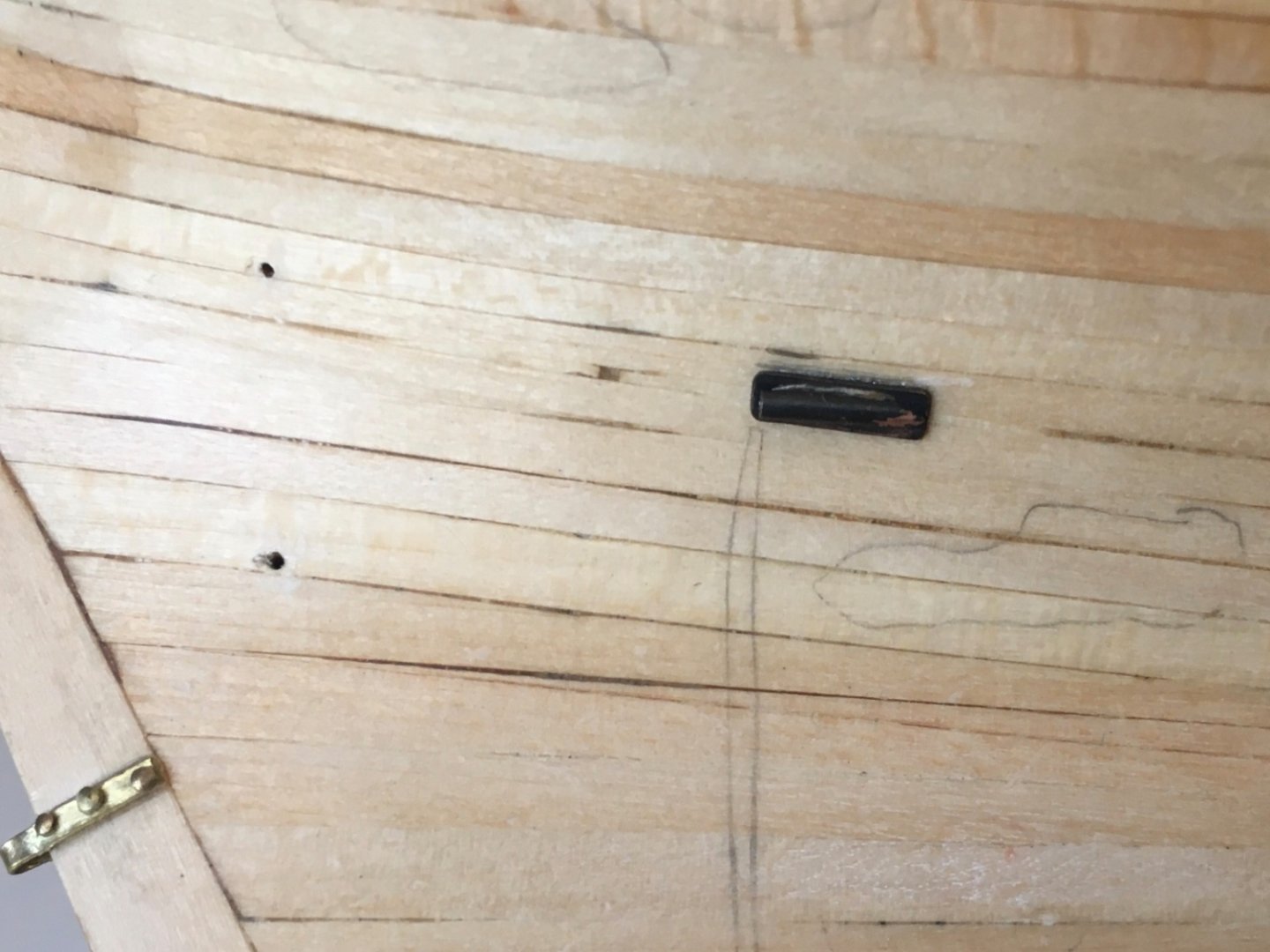
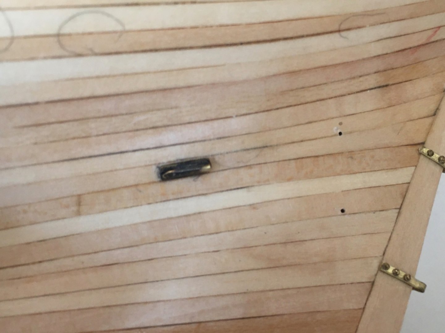
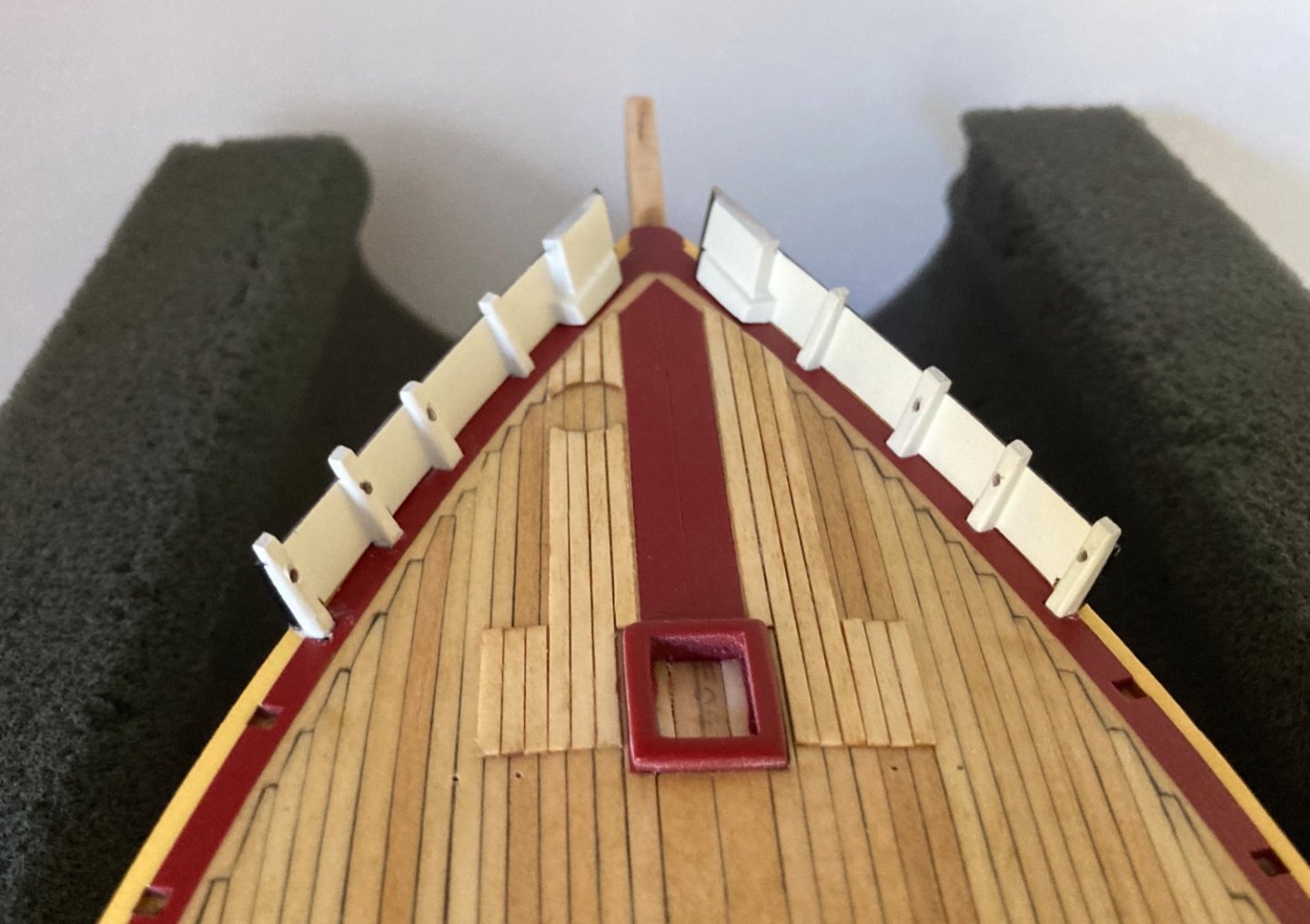
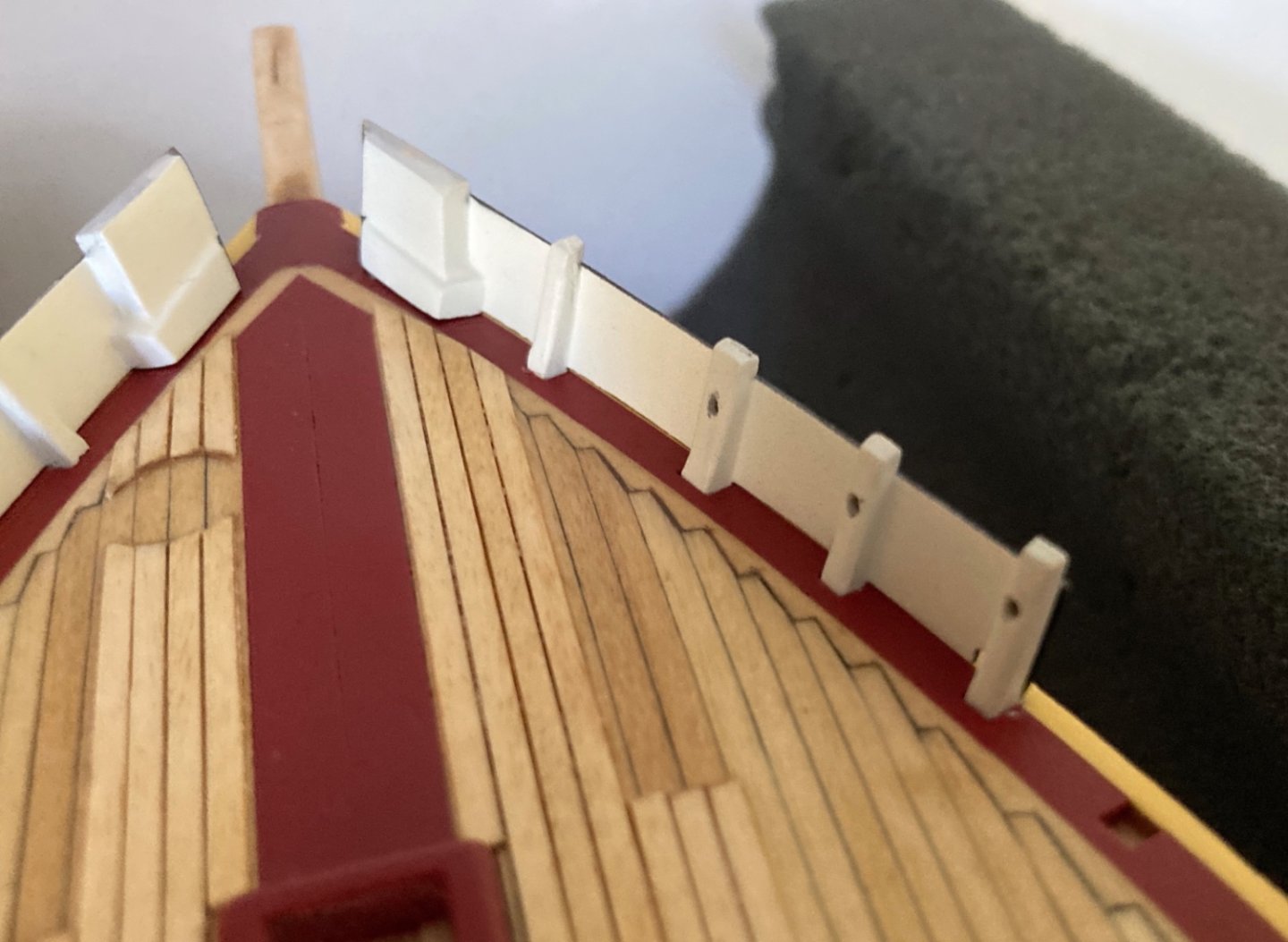
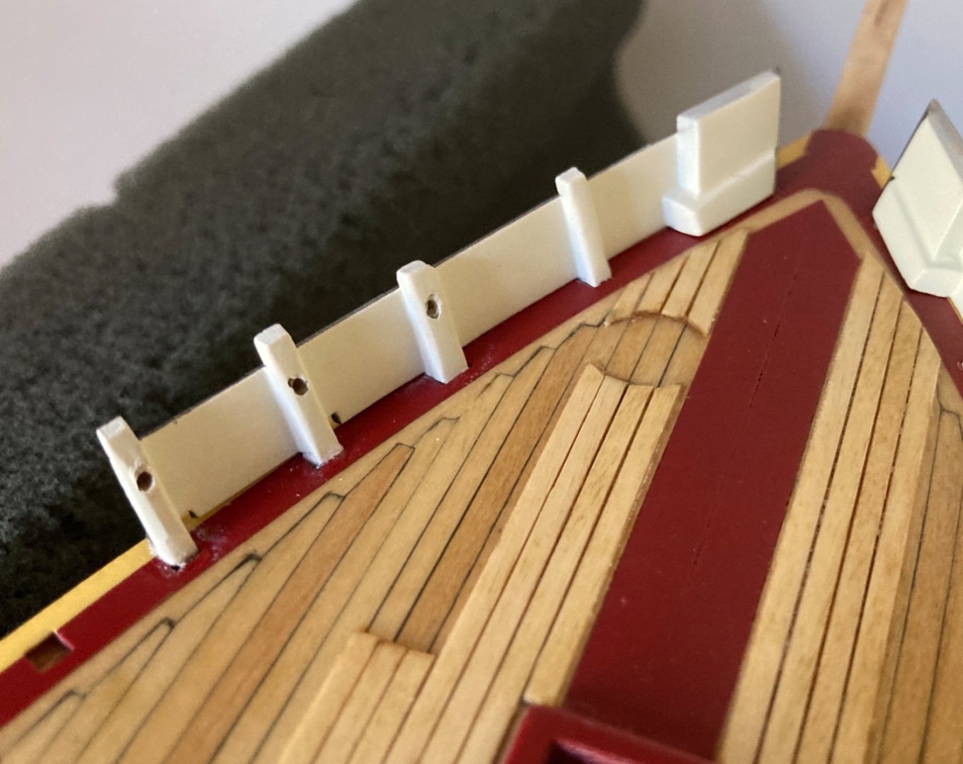
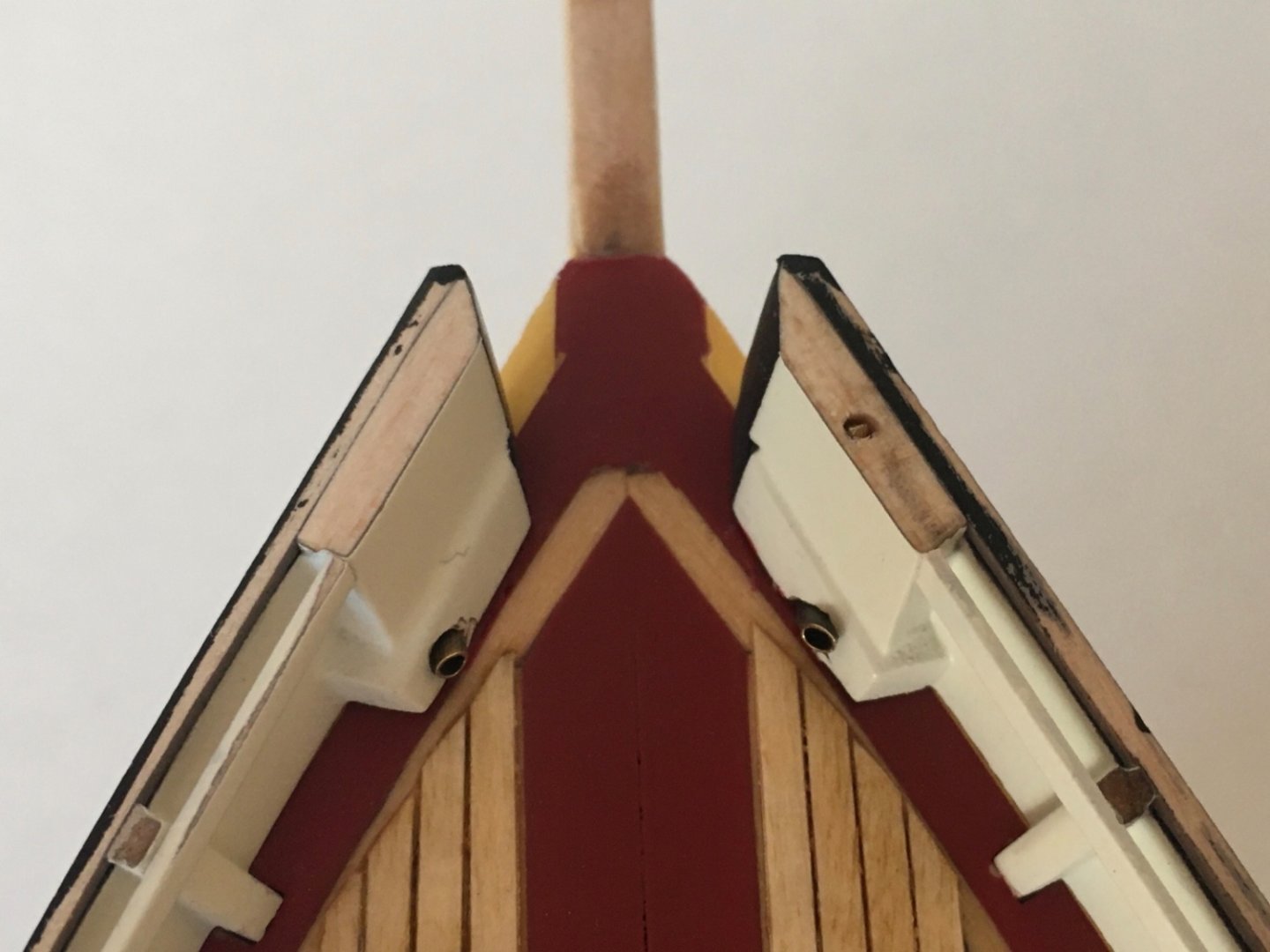
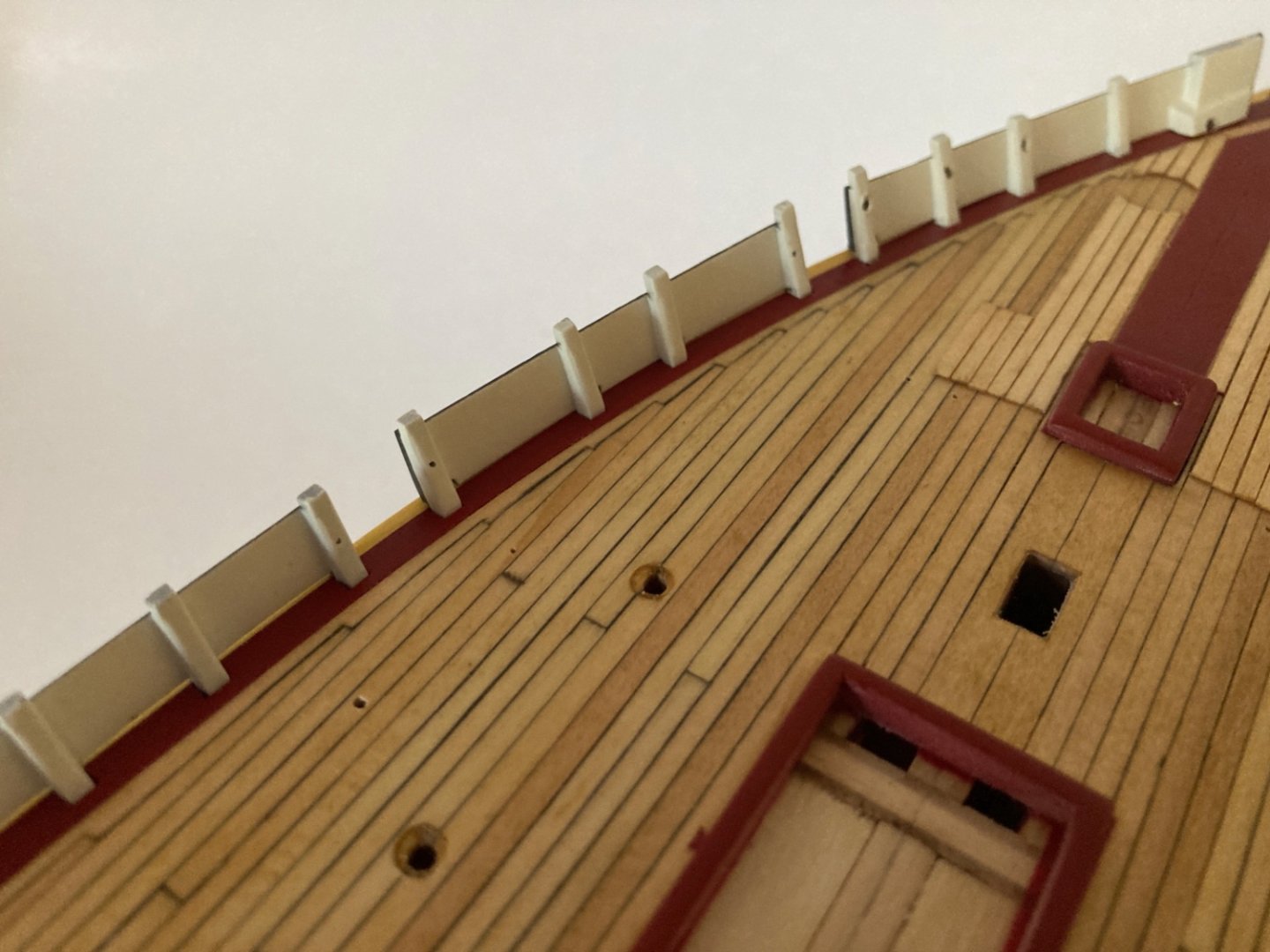
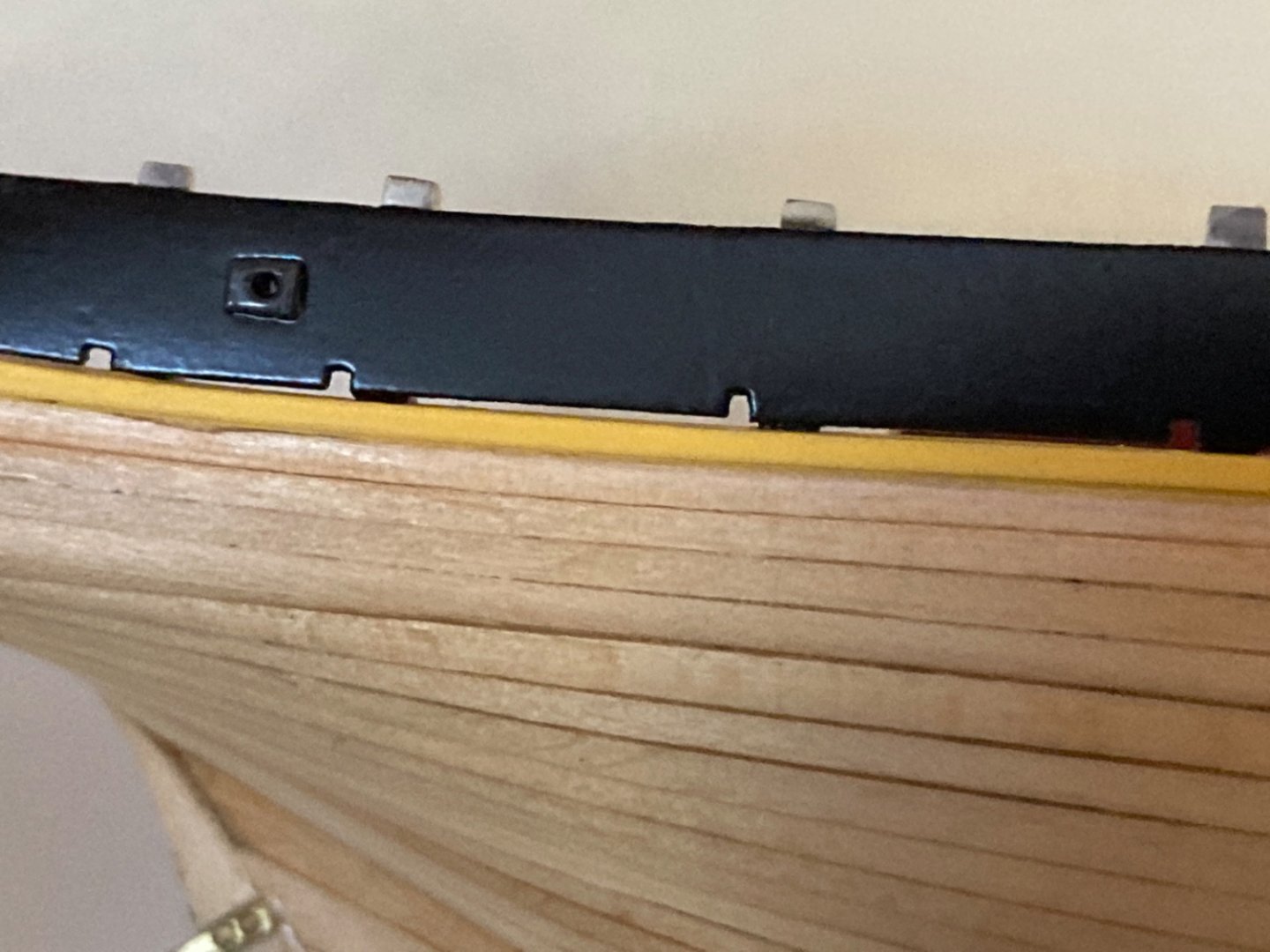
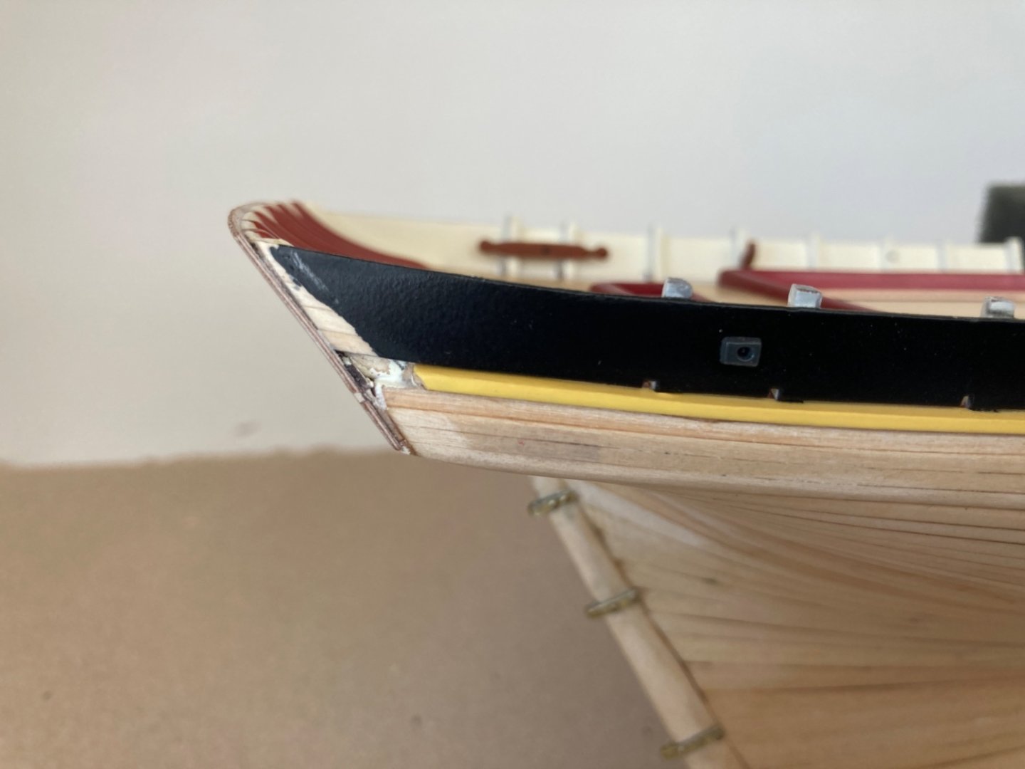
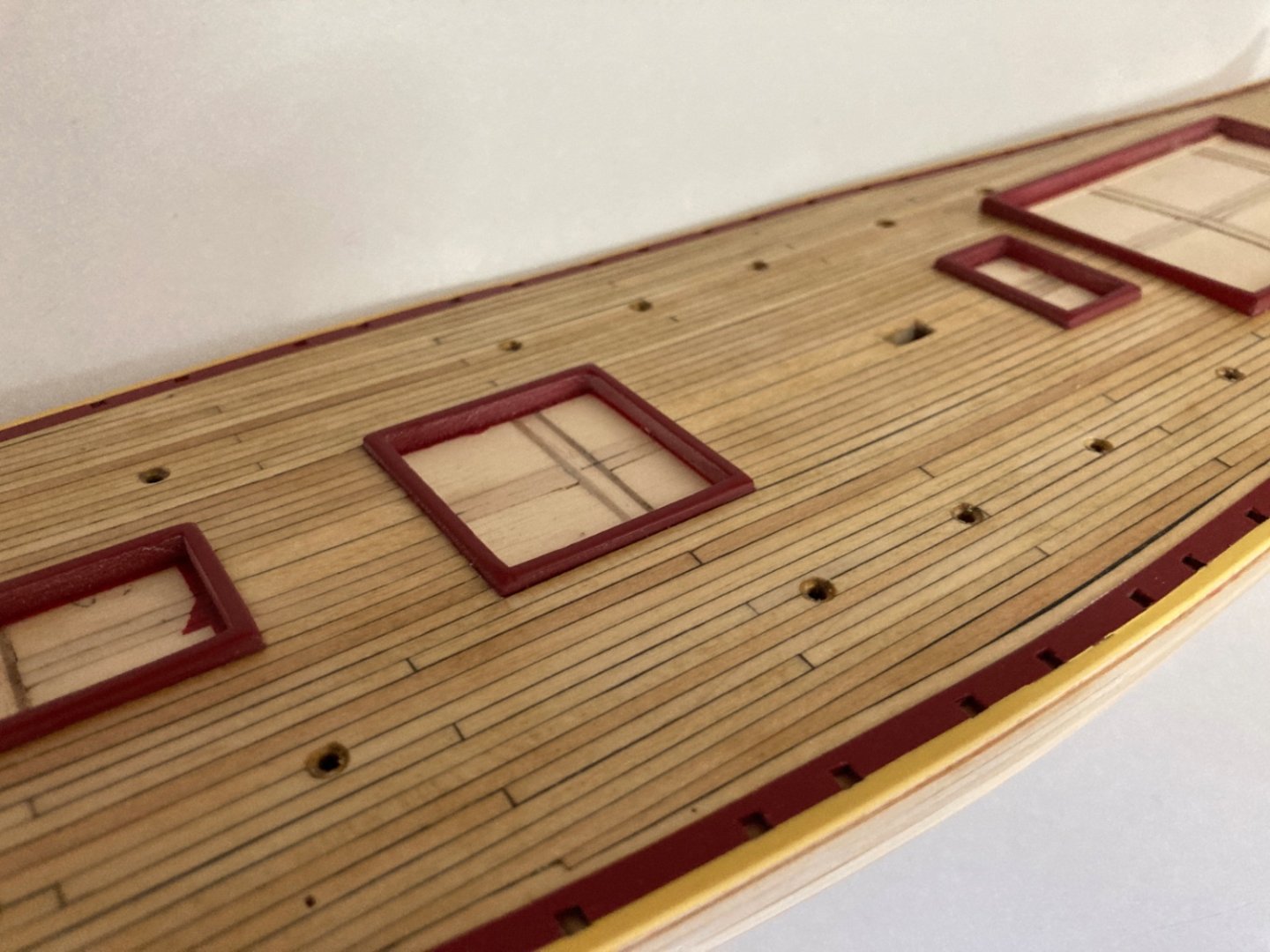
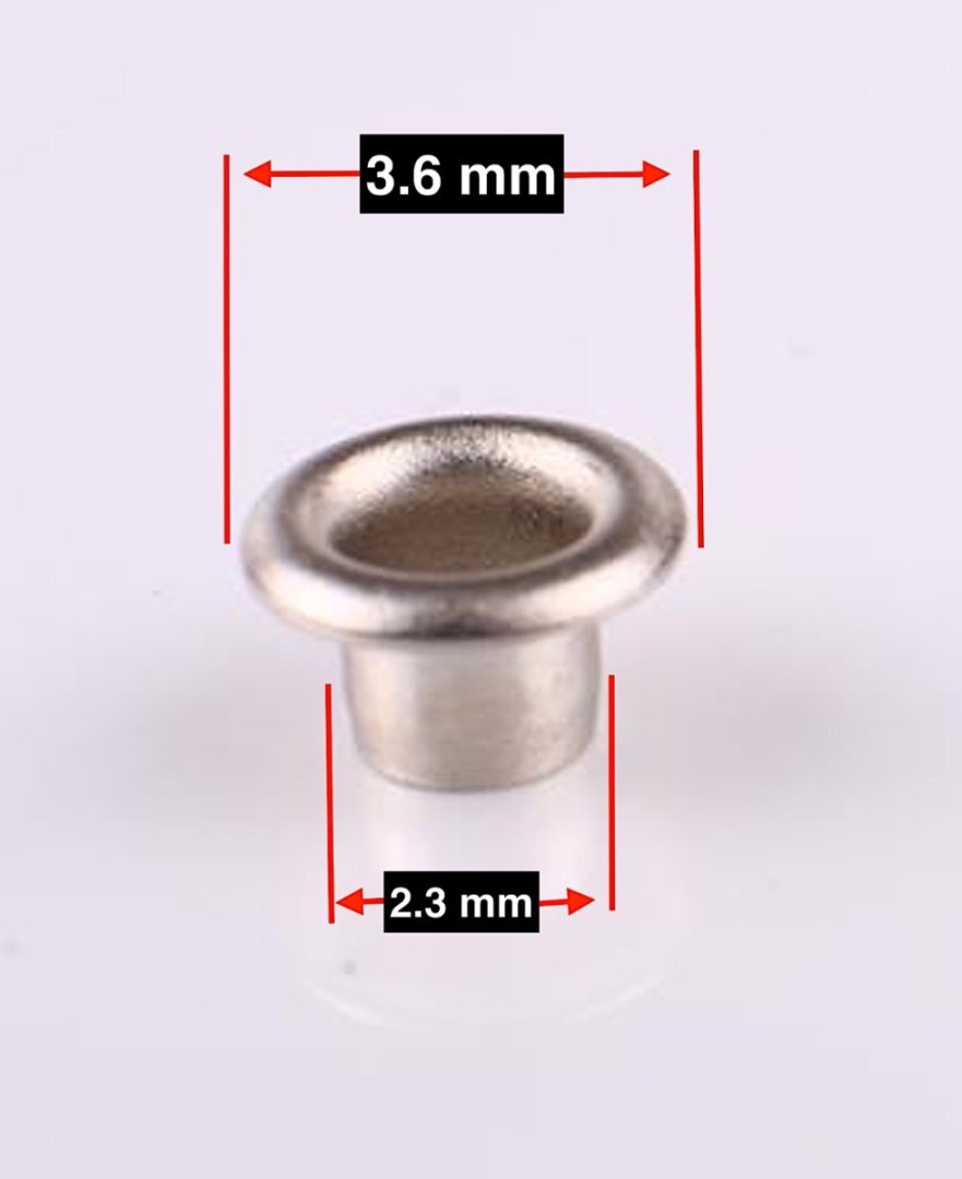
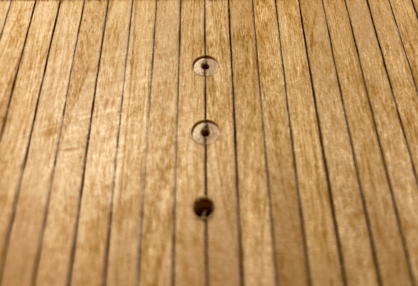
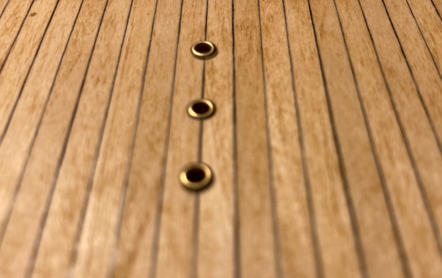
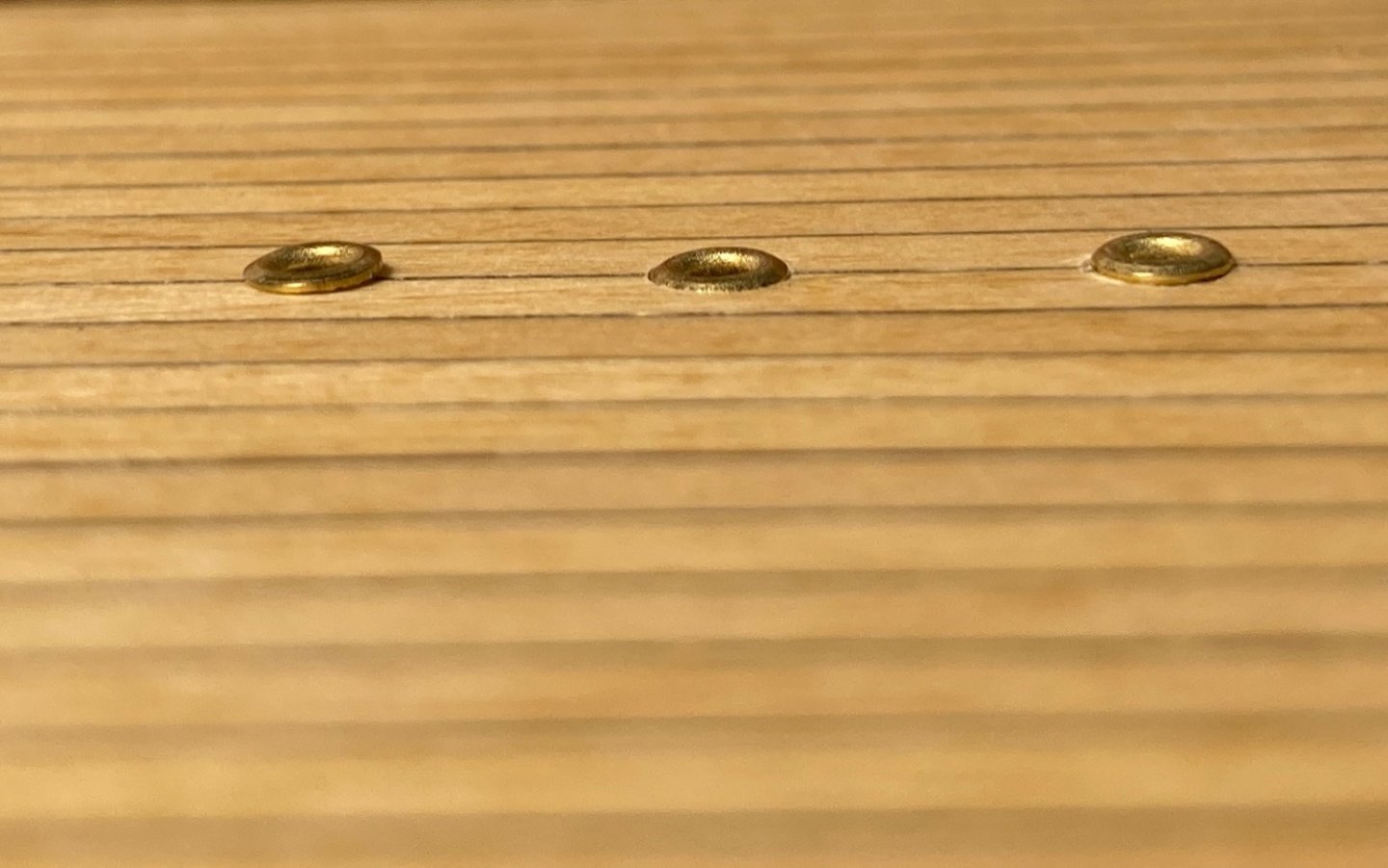
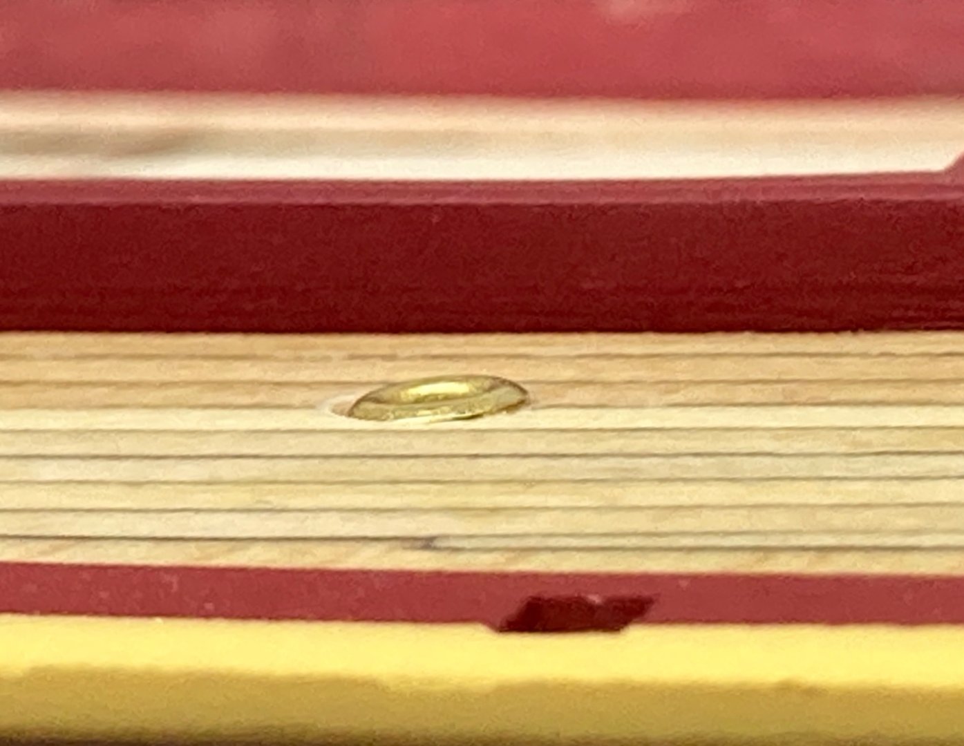
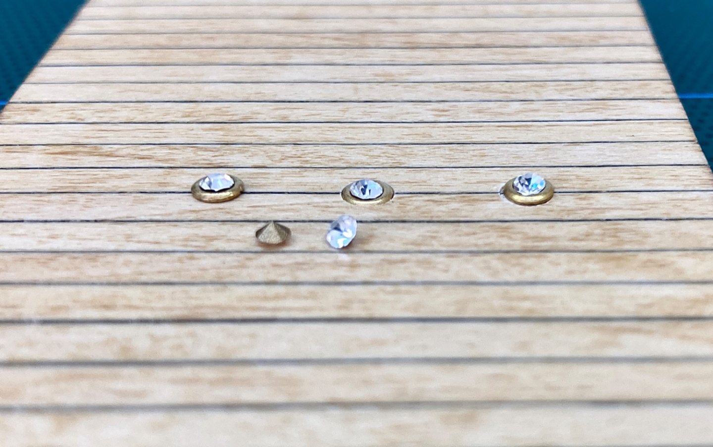
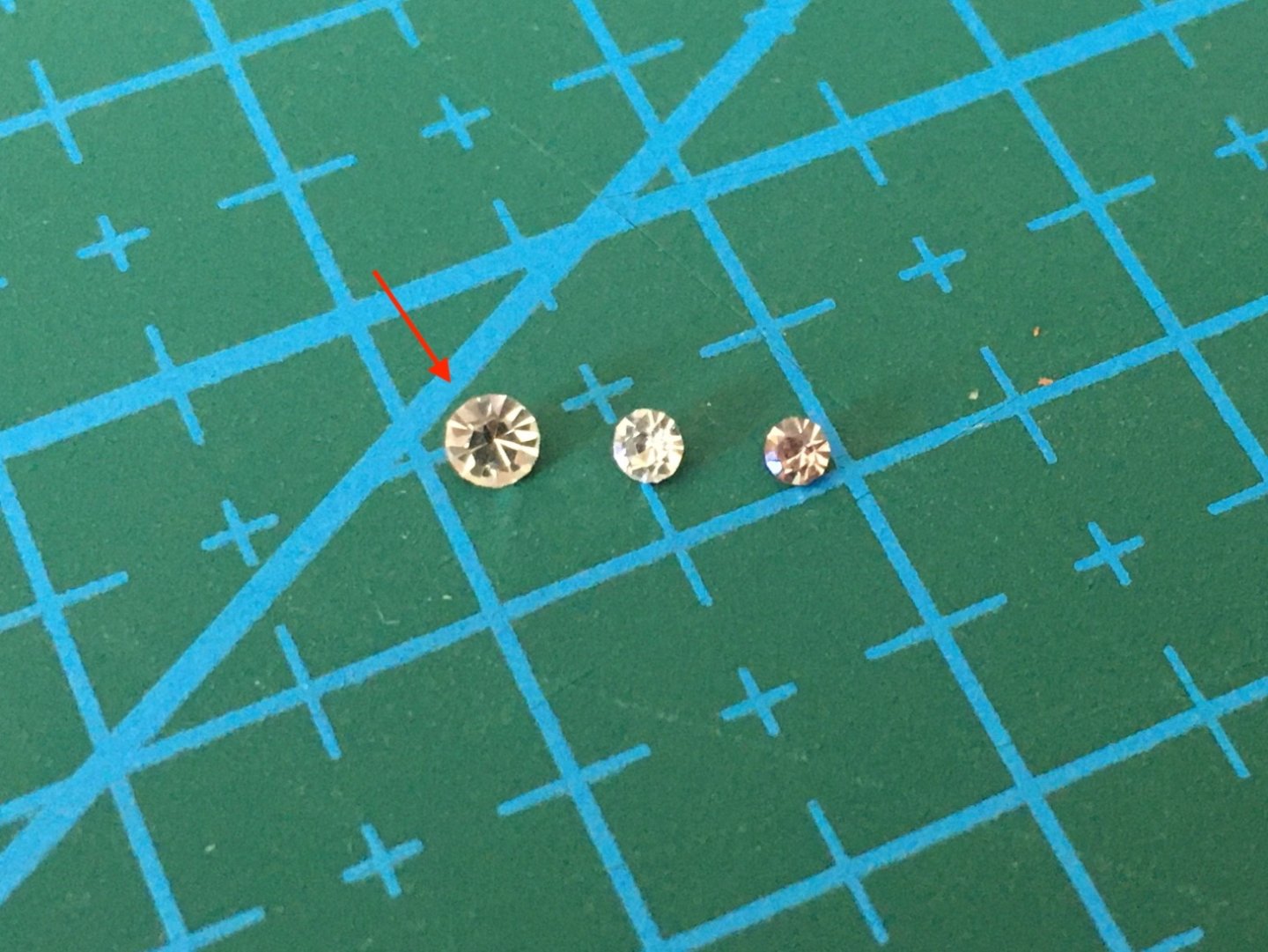
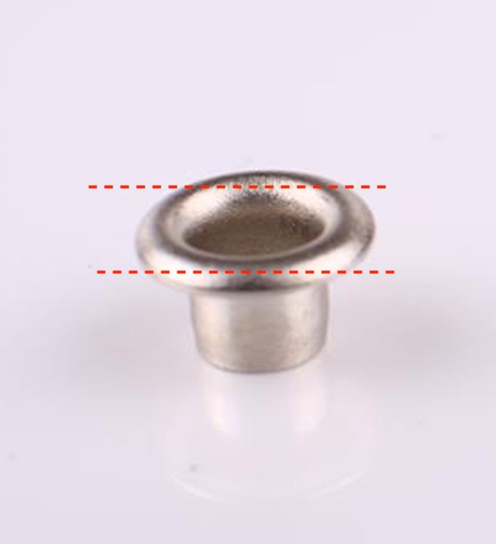
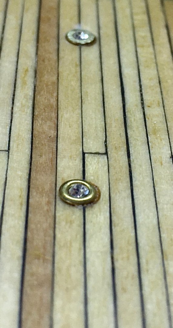
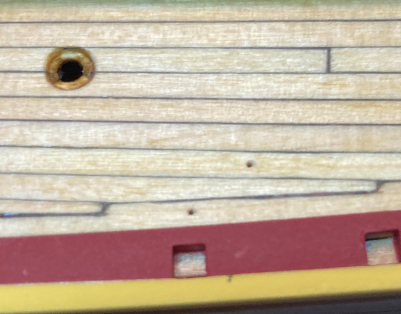
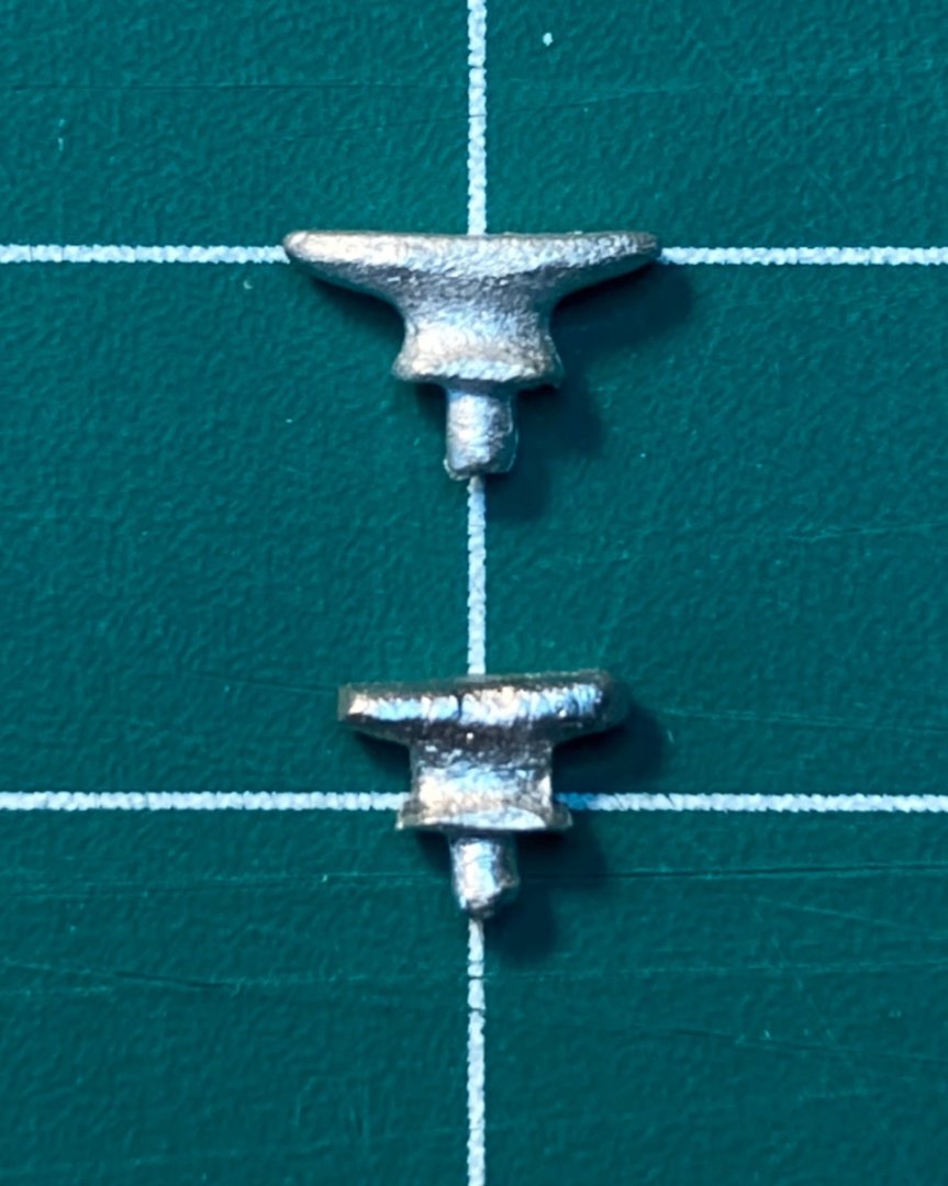
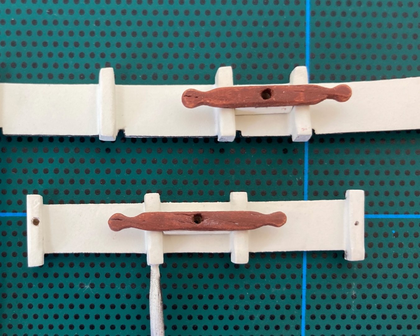
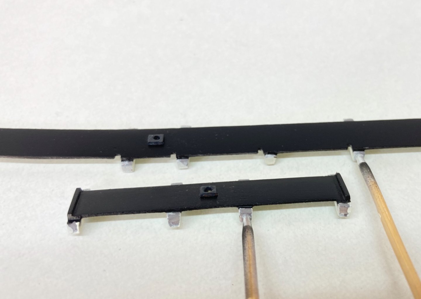
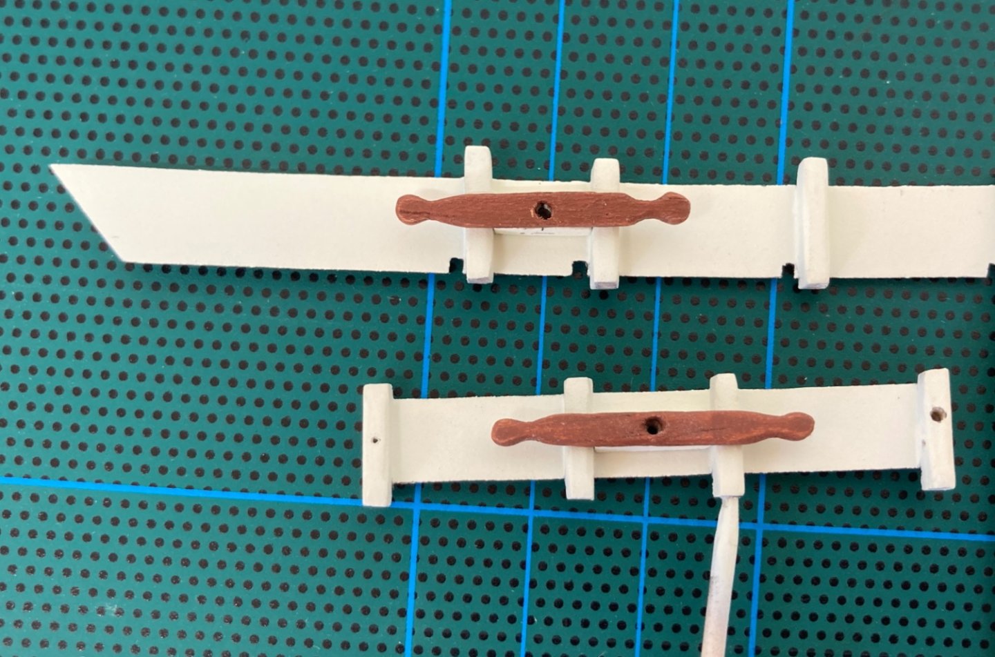
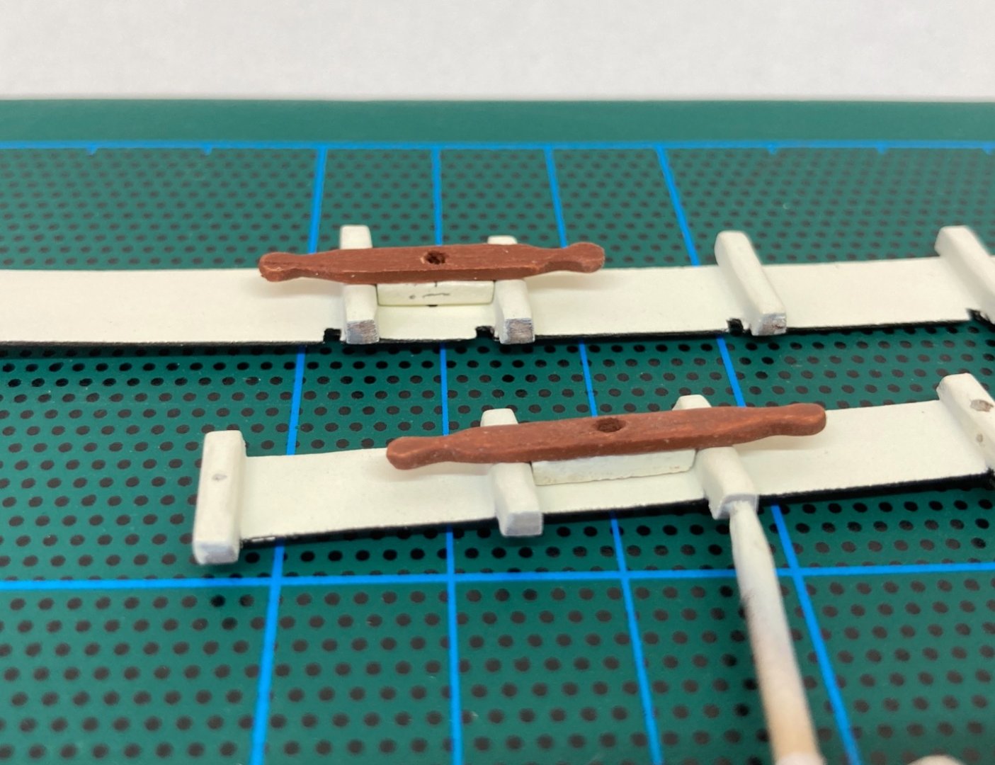
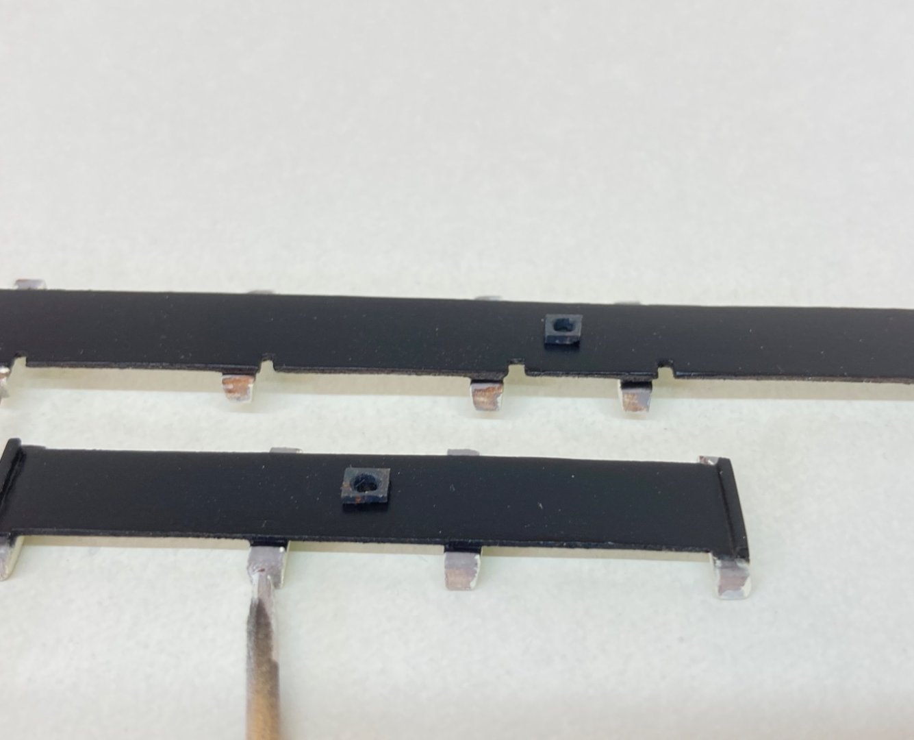
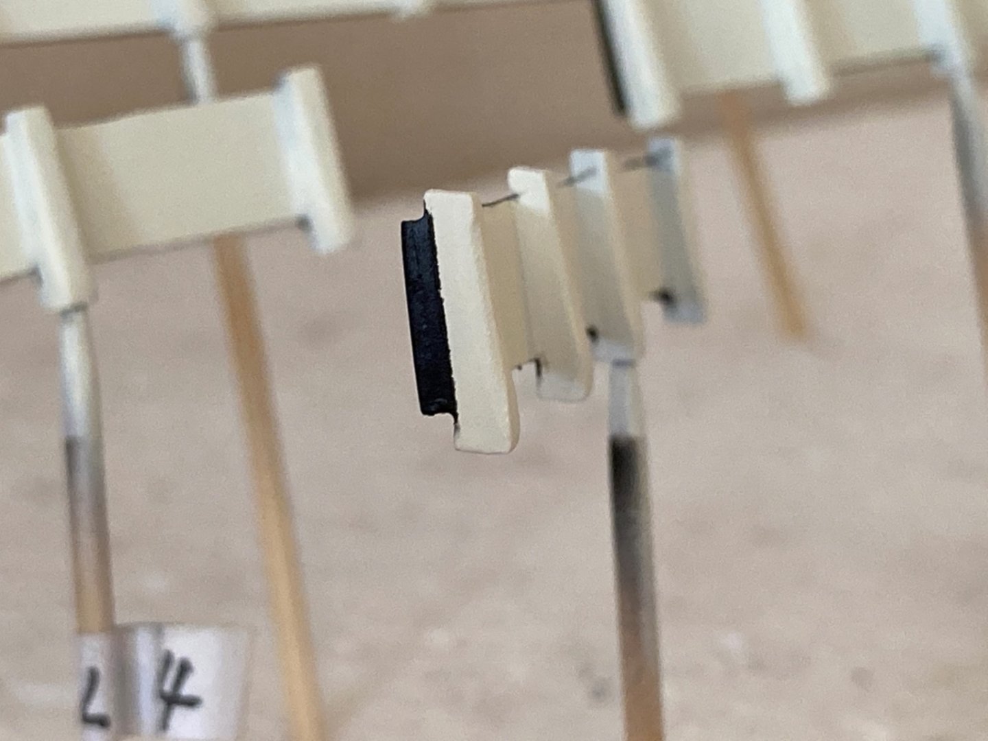
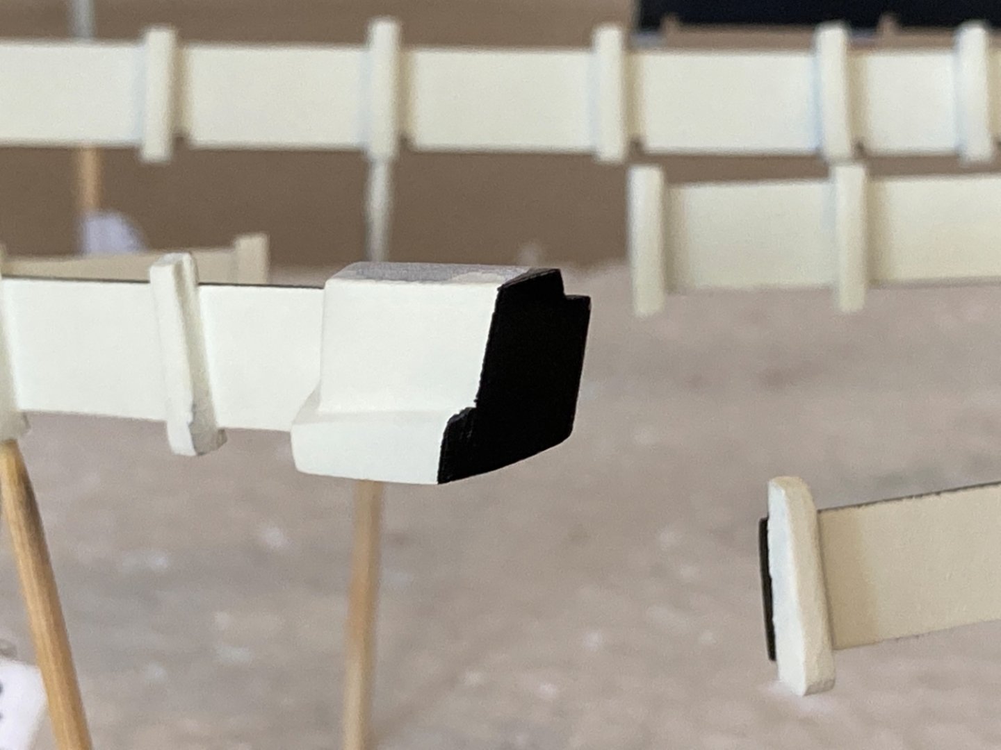
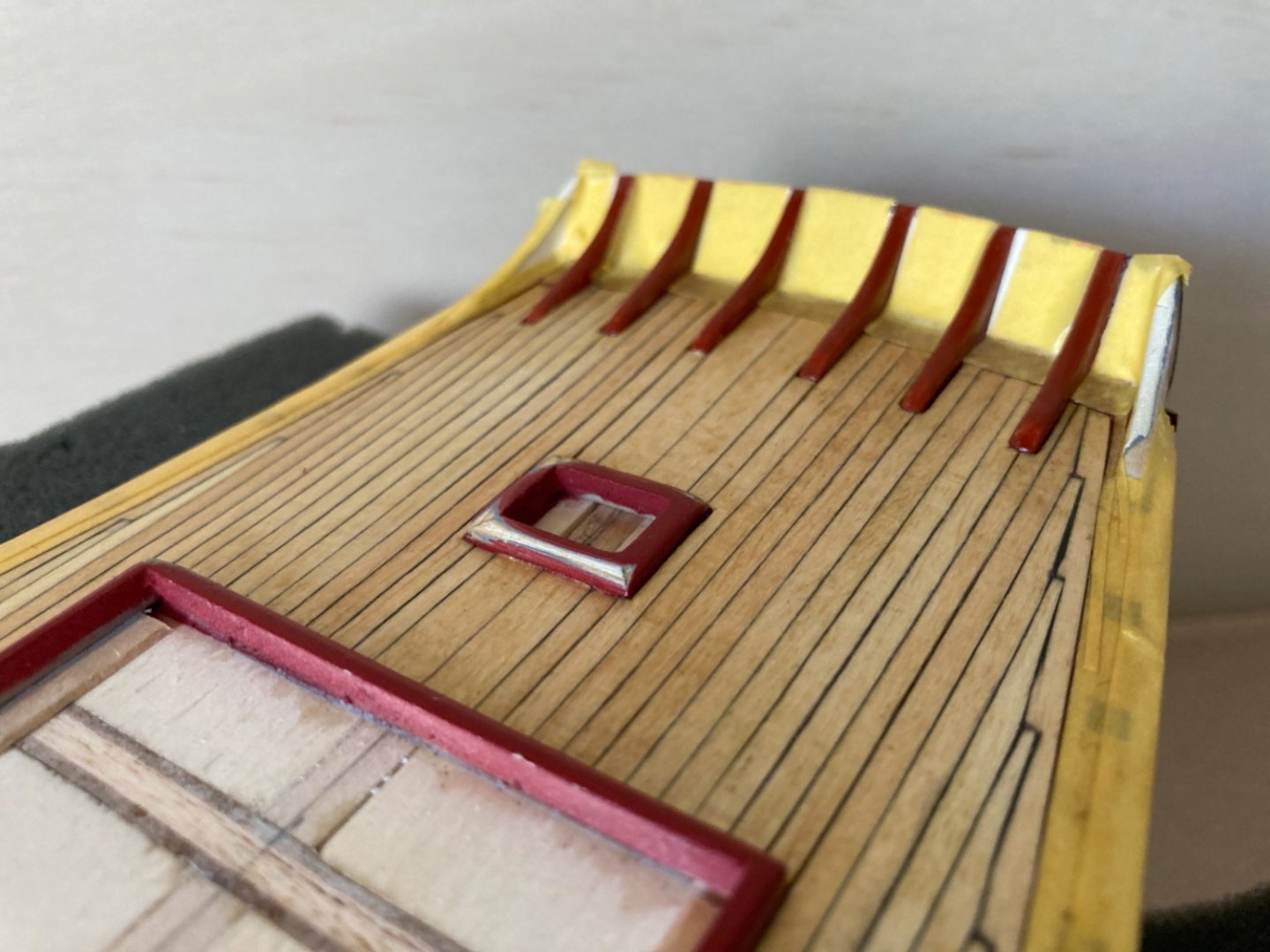
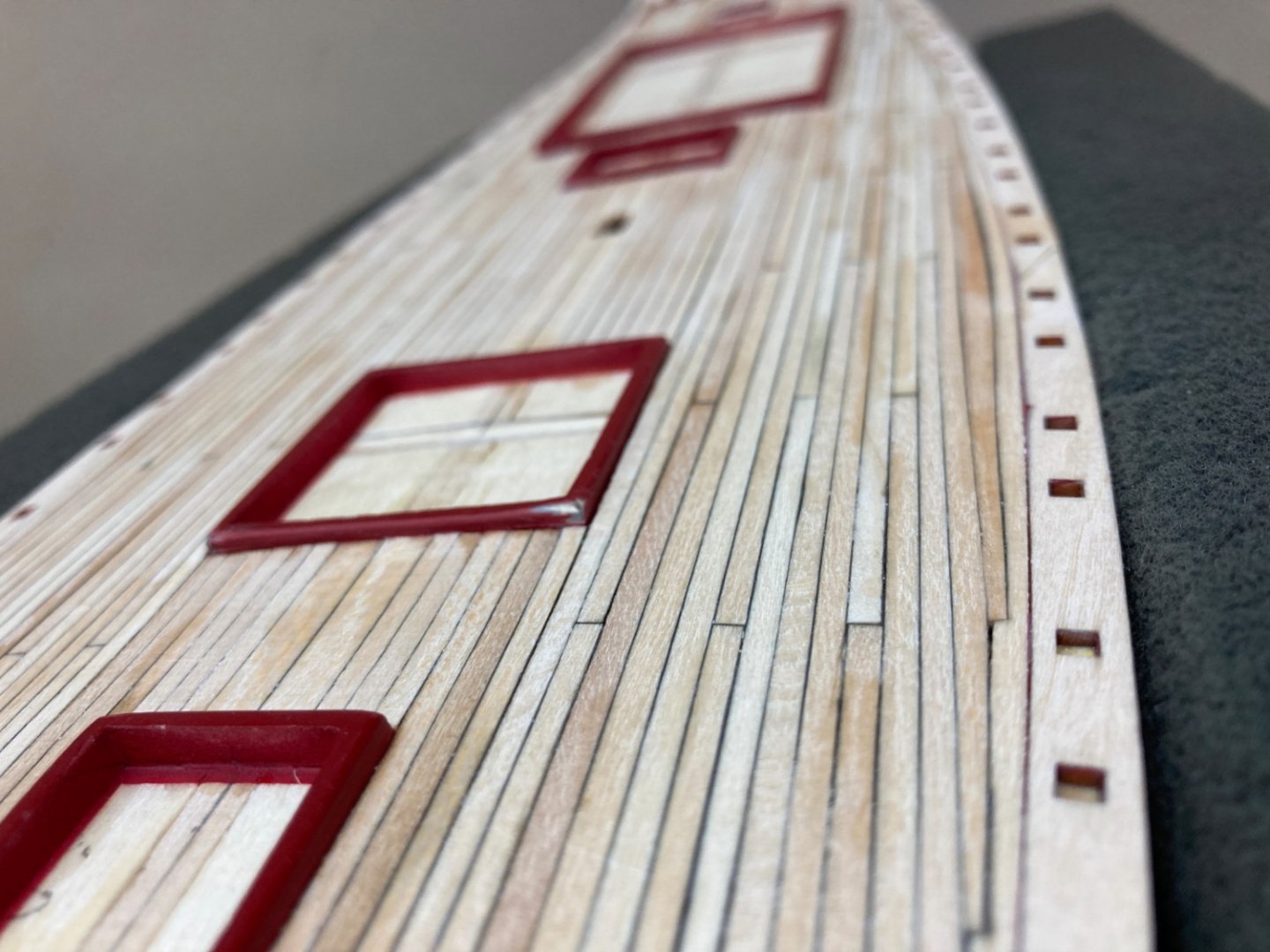
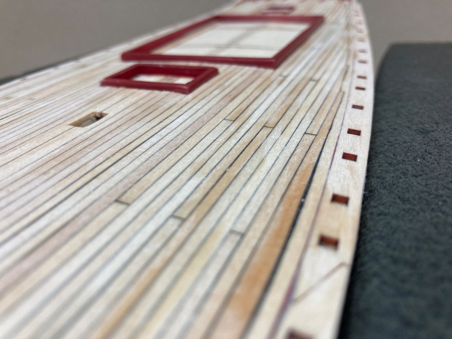
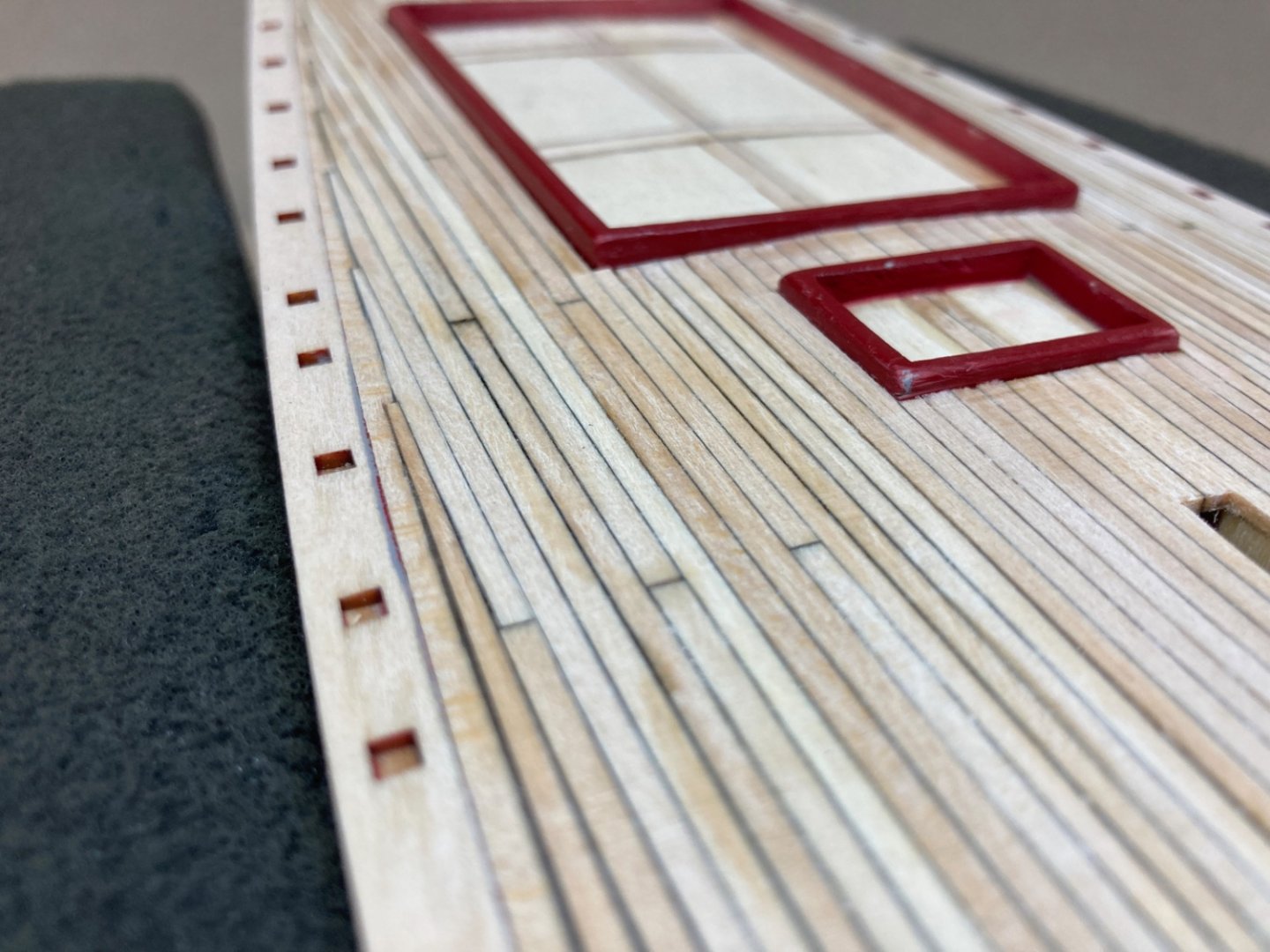
There are several holes on the deck and inboard sides of the bulwarks. These holes were for eyebolts, cleats and brass airport rings for light passage to below deck areas. I started with the holes for brass airport rings. The brass airport ring measurements are seen in the photo below. After marking the places on the deck ,with reference to the plans , with the tip of a needle, I decided to start drilling the holes by using a Dremel 4 mm wood drill bit and Dremel Micro hand piece deep enough to place the flange of the brass airport flush with deck level. Then enlarge the center hole to 2.4 mm size for full insertion of the airport. Drill Bits Before starting the job on the deck , I used already prepared and planked wood pieces for practice. Practice wood photos. Then I drilled the holes on the deck carefully. The airport rings dry fitted . Glass prisms were given by the kit. However those prisms were large and protrude upwards a lot which was not nice. Fortunately a friend of my who has jewelry hobby provided various smaller sizes of those prisms enabling much more acceptable results. Sorry for the low quality outoff focus below photo in which the prism given by the kit marked with red arrow. Later I decided to file the curved upper part of the airport flange to get a more realistic result. Probably down to the red dotted level. Dry fitting of the filed airport and comparison with the original ones. Again sorry for the quality of the photos. Here with the smaller size glass prisms. Then I continued with the holes on the deck. Those holes were for eyebolts and cleats. Drill bits 0.45 mm size for eyebolts and 1.2 mm size for cleats were used. Like the holes for airport rings, first the points for holes were marked with pin tips and holes were drilled first by the smallest size drill bit and gradually increasing the drill bit size up the the final size. Here there are holes which were not to be missed like the ones on the inboard sides of the outboard stern knees and the one right behind the slot for foremast. Please note the holes for airport rings were pine stain colored at this stage. The holes on the inboard sides of the bulwarks are also for cleats and eyebolts with rings. The holes were drilled out in the same manner . Although I tried to be careful , paint lifted off around some of the holes, especially the ones for cleats. Those areas were later revisited and repaired. Holes for cleats Holes for eyebolts Some of the holes for eyebolts have different locations I believe it is now the correct time to emphasise some of the out of scale metal parts given by the kit. The first example is the cleats. The kit stock cleats are way out of scale and have to be reduced. As seen on the photos below , and again sorry for the quality of them, I hope you get the idea. So before moving on I reduced the size of the cleats by filing. As there were a lot of them, the job took a long time.... The structures on the outboard and inboard sides of the bulwarks were prepared at this stage. Those structures are mooring chocks, cavels, solid blocks between the cavels and bulwark, and wood cleats for hanging life rings. They were dry fitted. Starboard side Port side


- 114 replies
-
- 2
-
-
- Pride of Baltimore II
- Model Shipways
- (and 1 more)
-
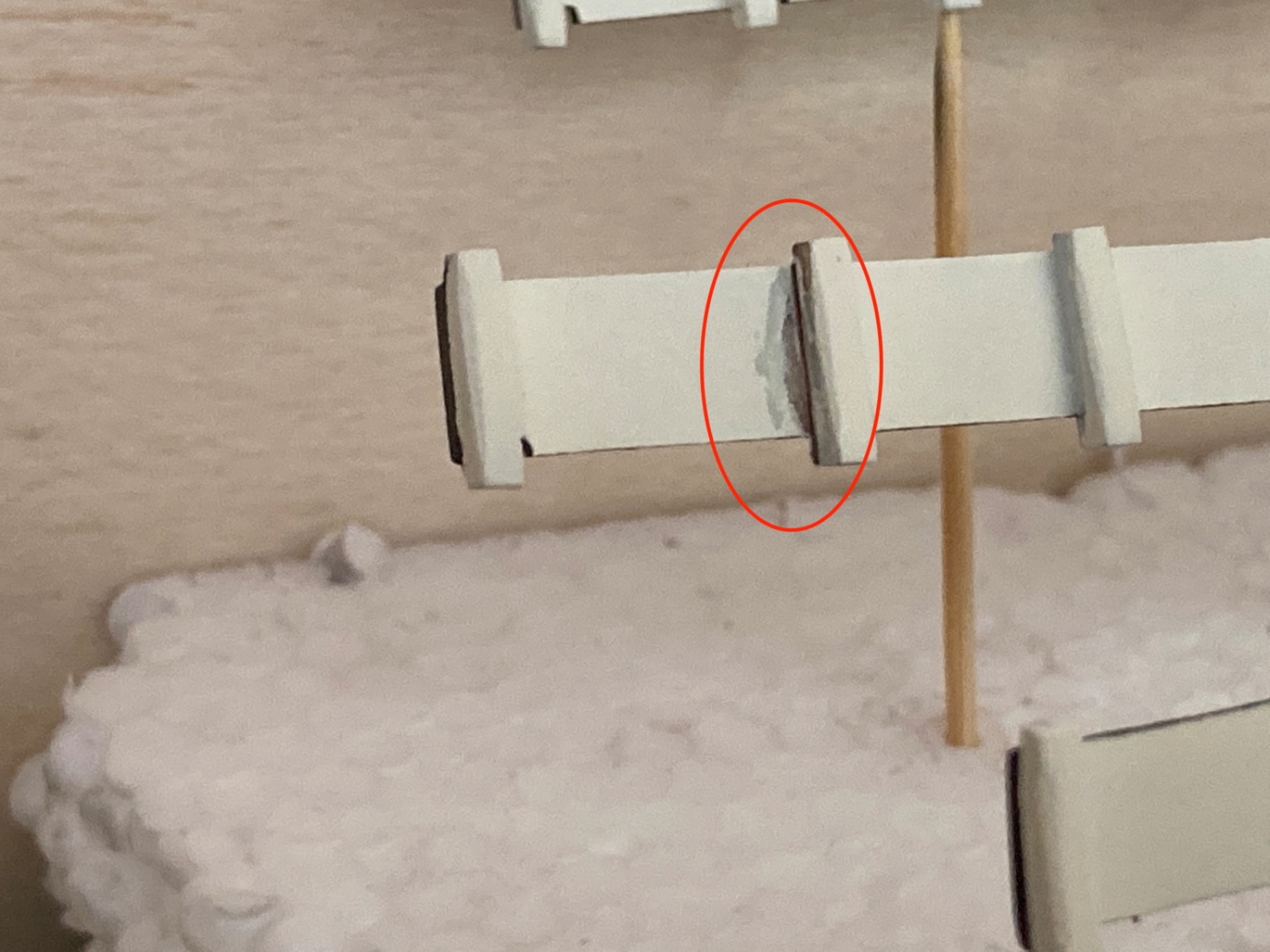
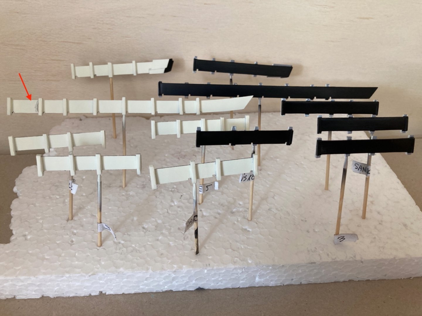
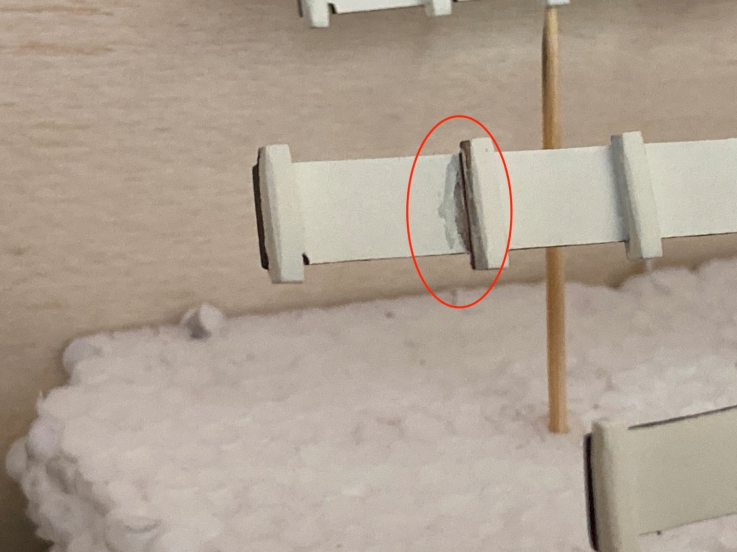
In the next step I painted the sheer planks , coamings, stern knees and upper transom inboard again. This was the final ! painting of those parts. Then I did the painting job on bulwarks. After the grey primer coat ( I used a 1 lt can of commercial grey primer diluted by commercial lacquer thinner) , the inboards were painted first with light cream color and the outboards followed with black. Although I waited for 48 hours, a moment of carelessness , during removing the masks , caused paint liftoff in a small inboard area which was repaired by airbrushing that section again. Photo after grey primer. After painting the in and outboard sides with light cream and black (Both colors are 100 ml cans of acrylic auto paint diluted with commercial acrylic thinner). Red arrow and ellipse indicate the paint liftoff area. At this stage previously prepared inboard and outboard stringers were painted also. Inboard strips were painted light cream and outboard ones with black. By the way all colors used so far were matt. Inboard stringers Outboard stringers Those stringers above were prepared more than necessary in order to have backup ones ready if need arises.

- 114 replies
-
- 3
-
-
- Pride of Baltimore II
- Model Shipways
- (and 1 more)
-
Thank you Yves I really do appreciate your comments. Have a nice day.
- 114 replies
-
- 2
-
-
- Pride of Baltimore II
- Model Shipways
- (and 1 more)
-
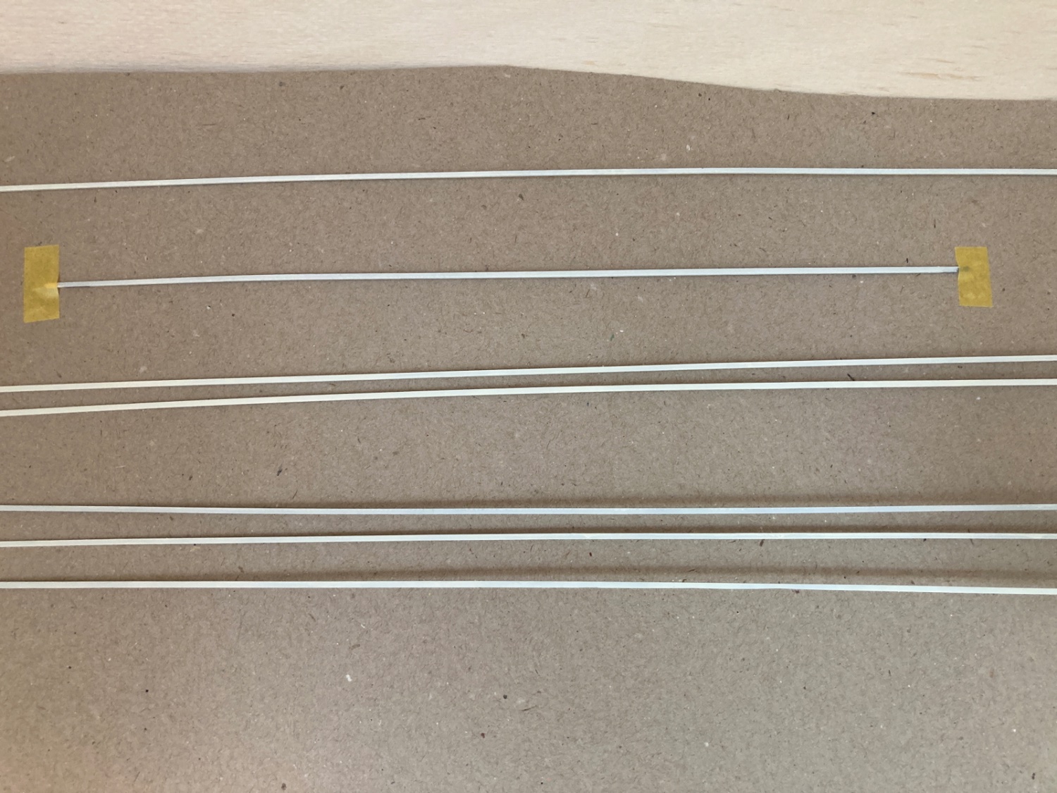
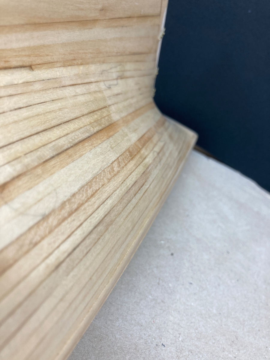
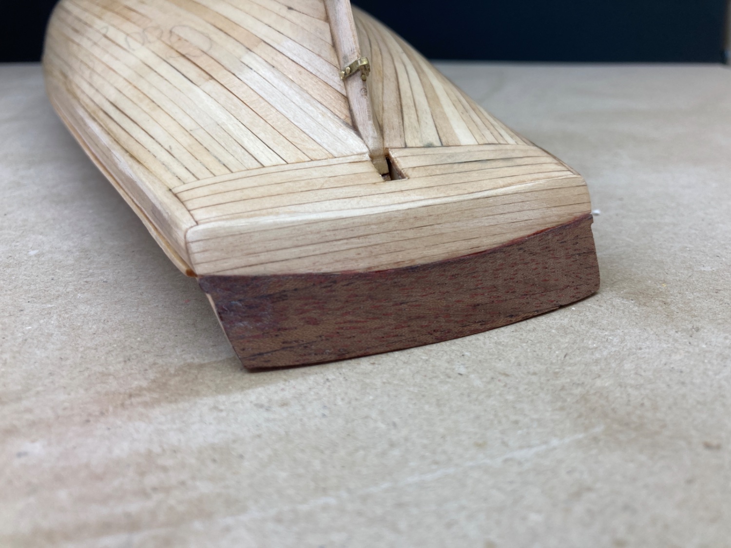
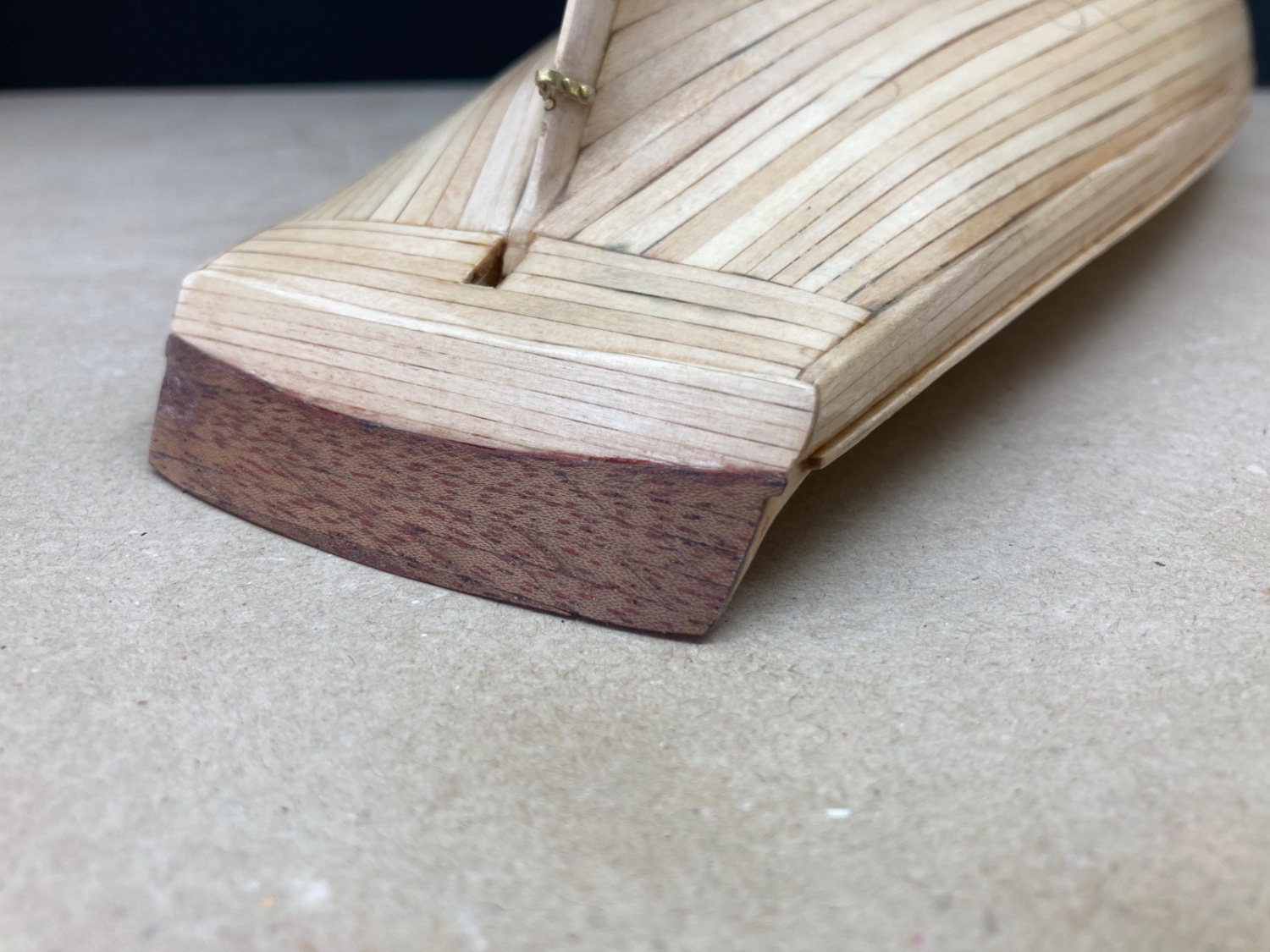
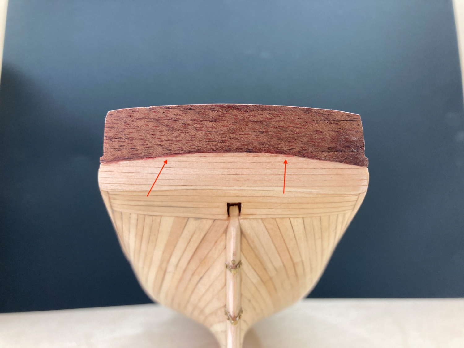
Then came the sanding sealer job stage. Sanding sealer was airbrushed first on the deck planking , followed by the hull and transom and finally to the already prepared bulwark sections and rudder . A total of 5 coats were applied . Sanding sealer/lacquer thinner ratio was 1:1.25 in the first two coats and was 1:1.5 in the final 3 coats. I used Paache Single action bottom feed airbrush , using a pressure of around 1 Bar for the job. Before the application of the 5th coat and especially on the hull, the points which are not yet fully covered by sanding sealer were filled with undiluted sanding sealer using a brush. Between the coats and after the final coat , the surfaces were sanded by 400 grit sanding paper cover blocks. The masking of the deck after its sanding sealer job is done. Bulwarks and rudder. Please note that the bulwark sections are location number and side coded. The photos of the deck , hull and transom after sanding sealer application followed by 400 grit sanding. Please note the red color of the first two middle deck planks at bow were also sanded, however the red silhouette between them and neighboring deck planks is visible. In the final photo of this post below, you see some different color at the border of mahogany and basswood planks indicated by red arrows. It is the color of mahogany stain which I brushed to upper mahogany transom. However I decided not to use it and sanded it off. As the border will be covered with a thin wood and the lower basswood transom be painted yellow, the residual coloration was ignored.


- 114 replies
-
- 5
-
-
- Pride of Baltimore II
- Model Shipways
- (and 1 more)
-
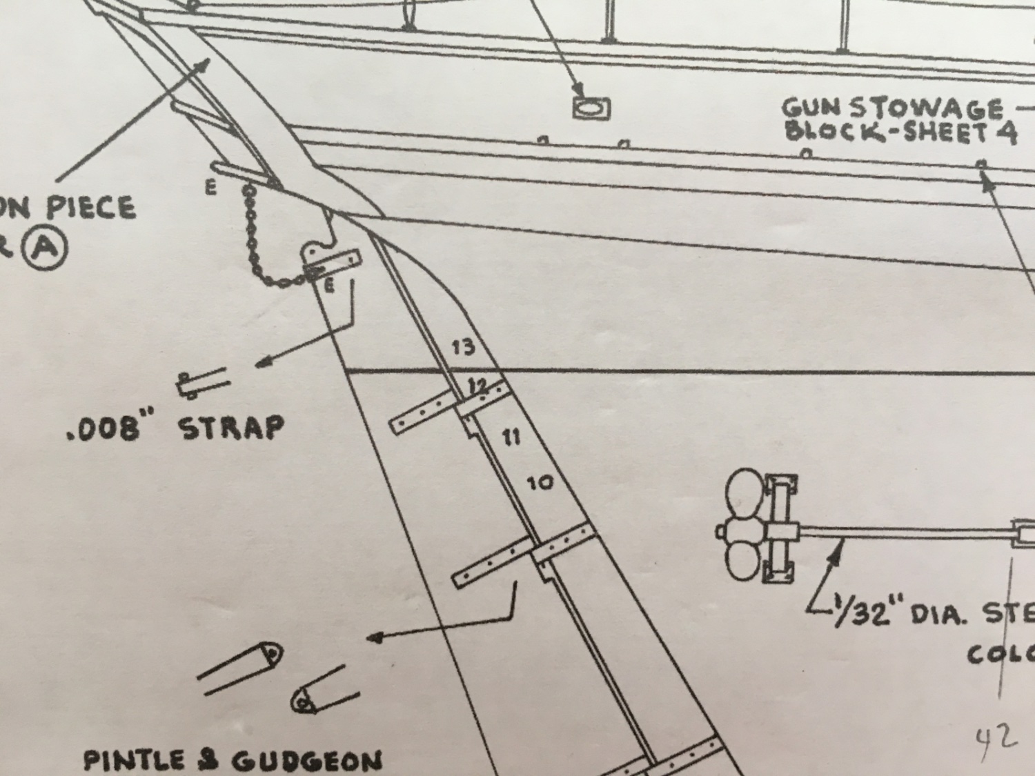
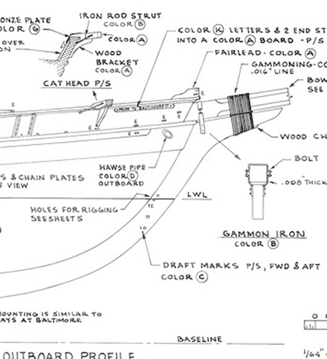
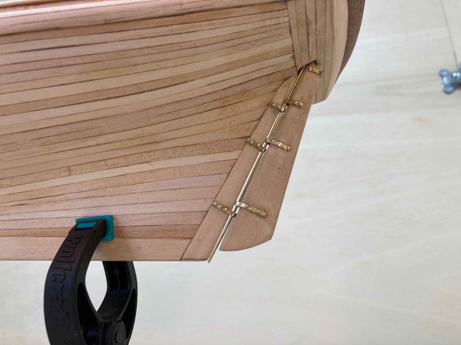
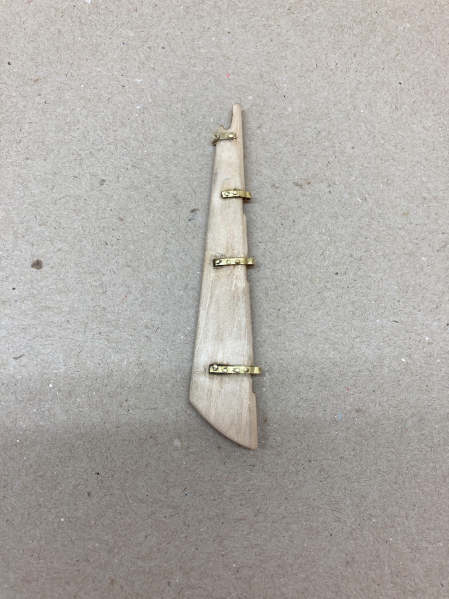
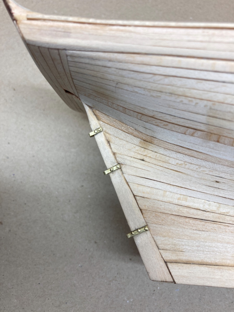
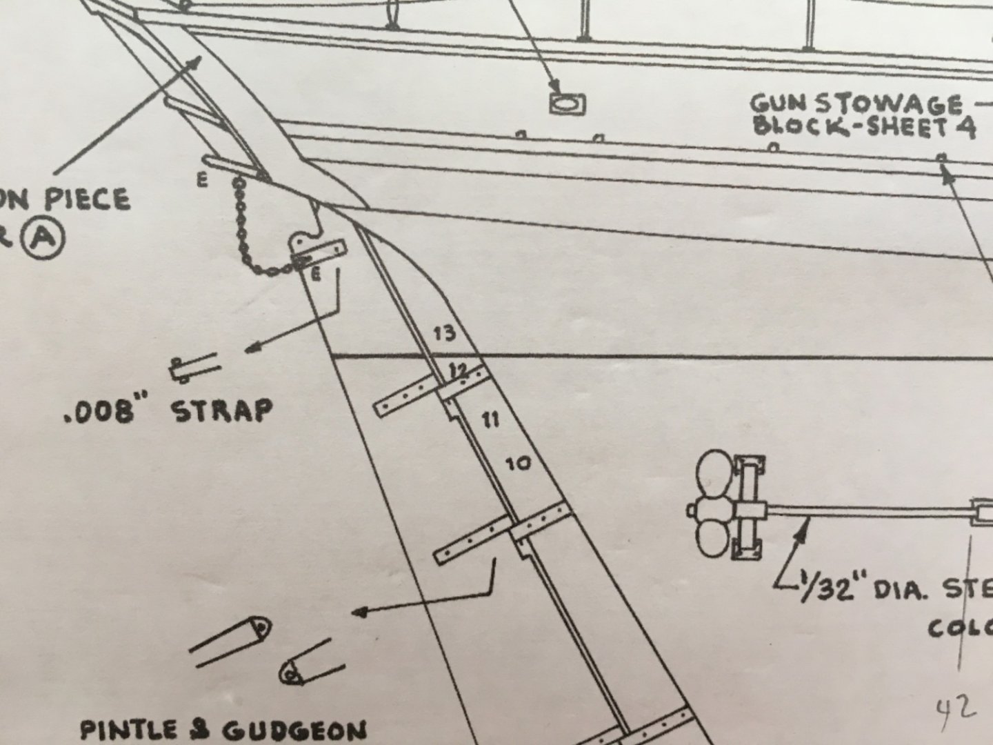
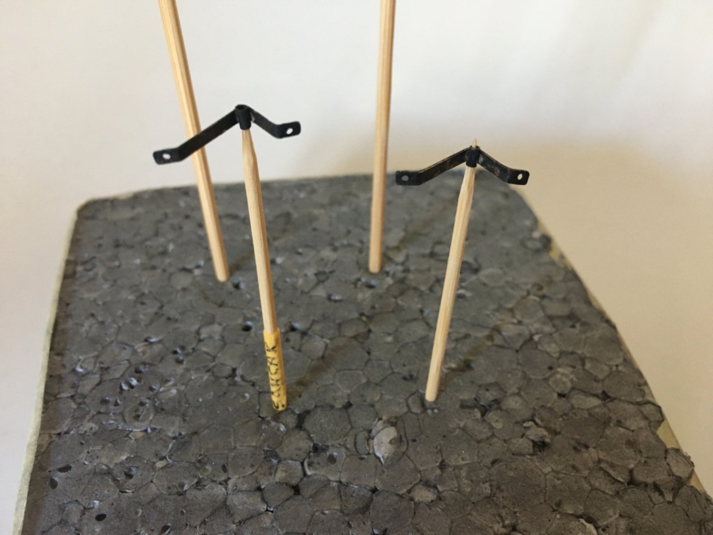
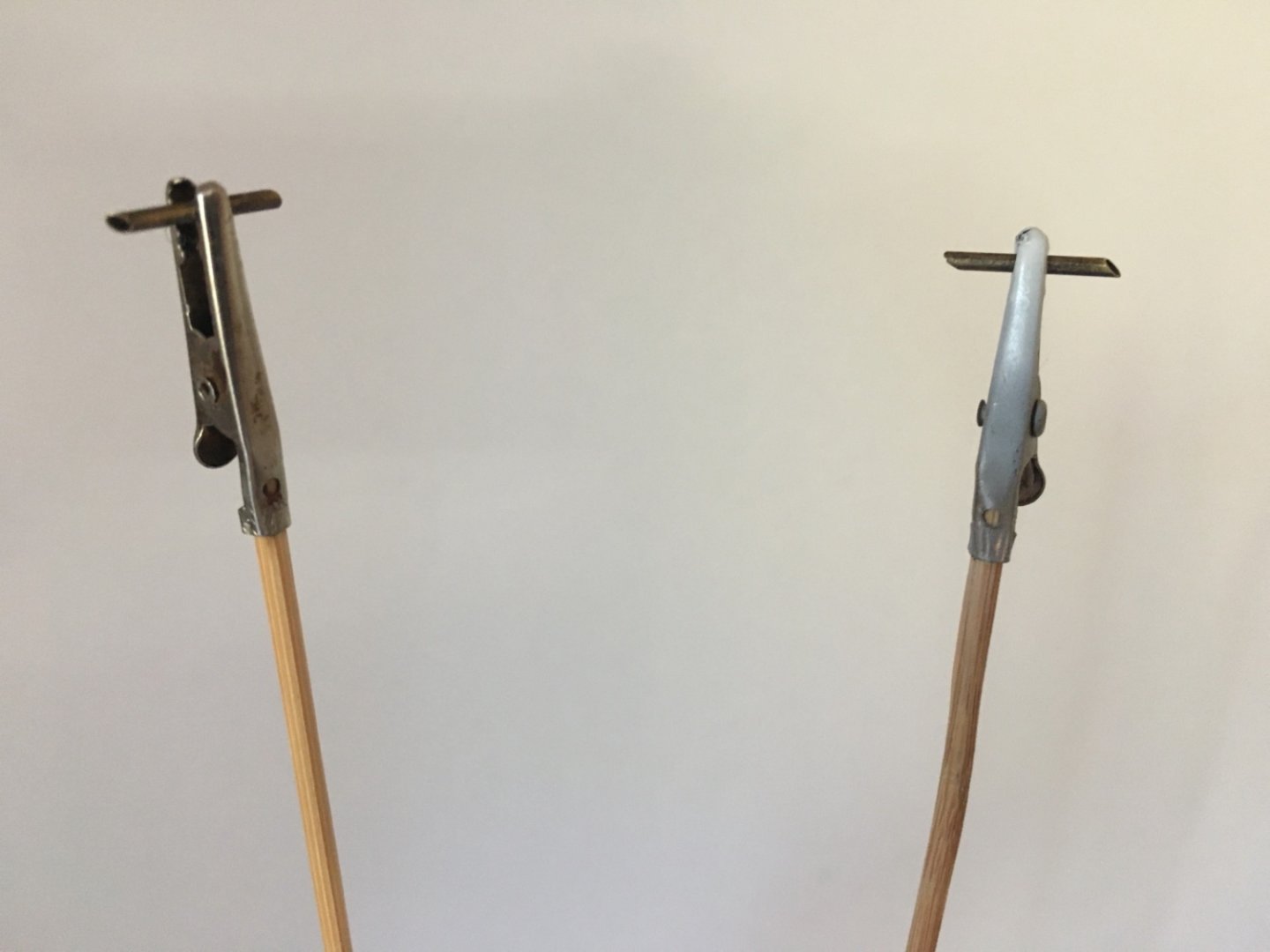
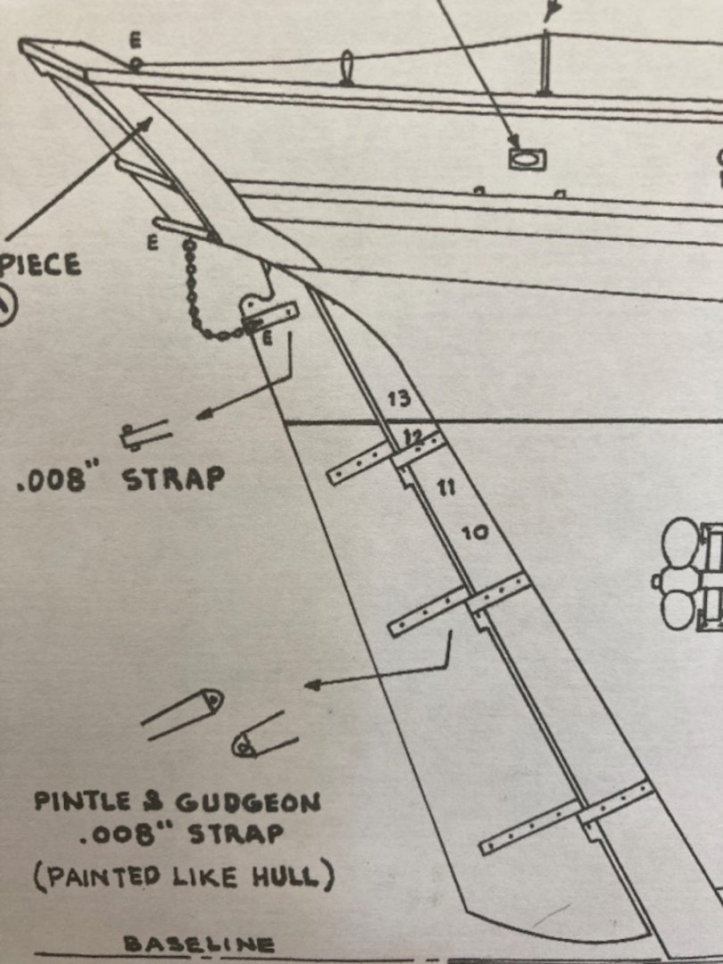
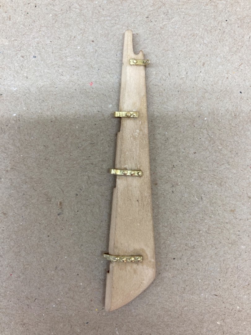
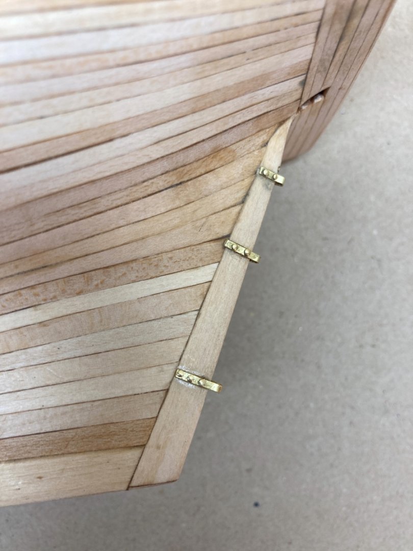
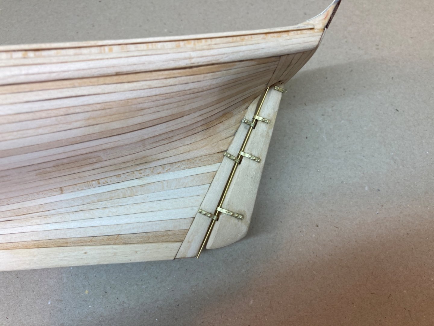
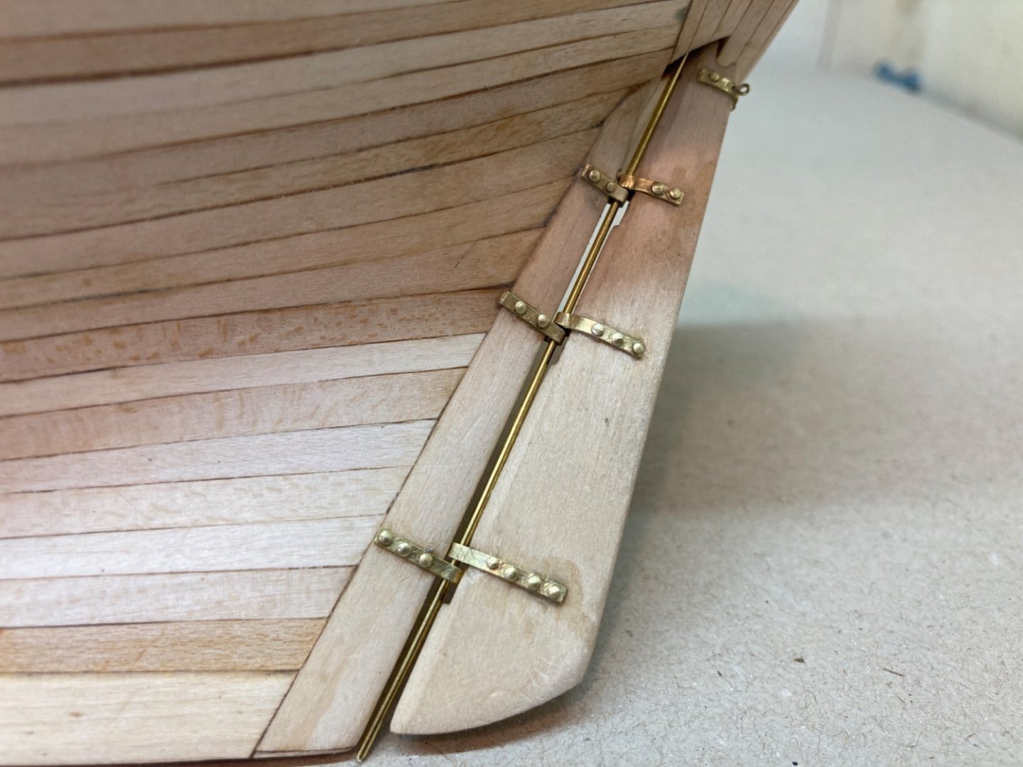
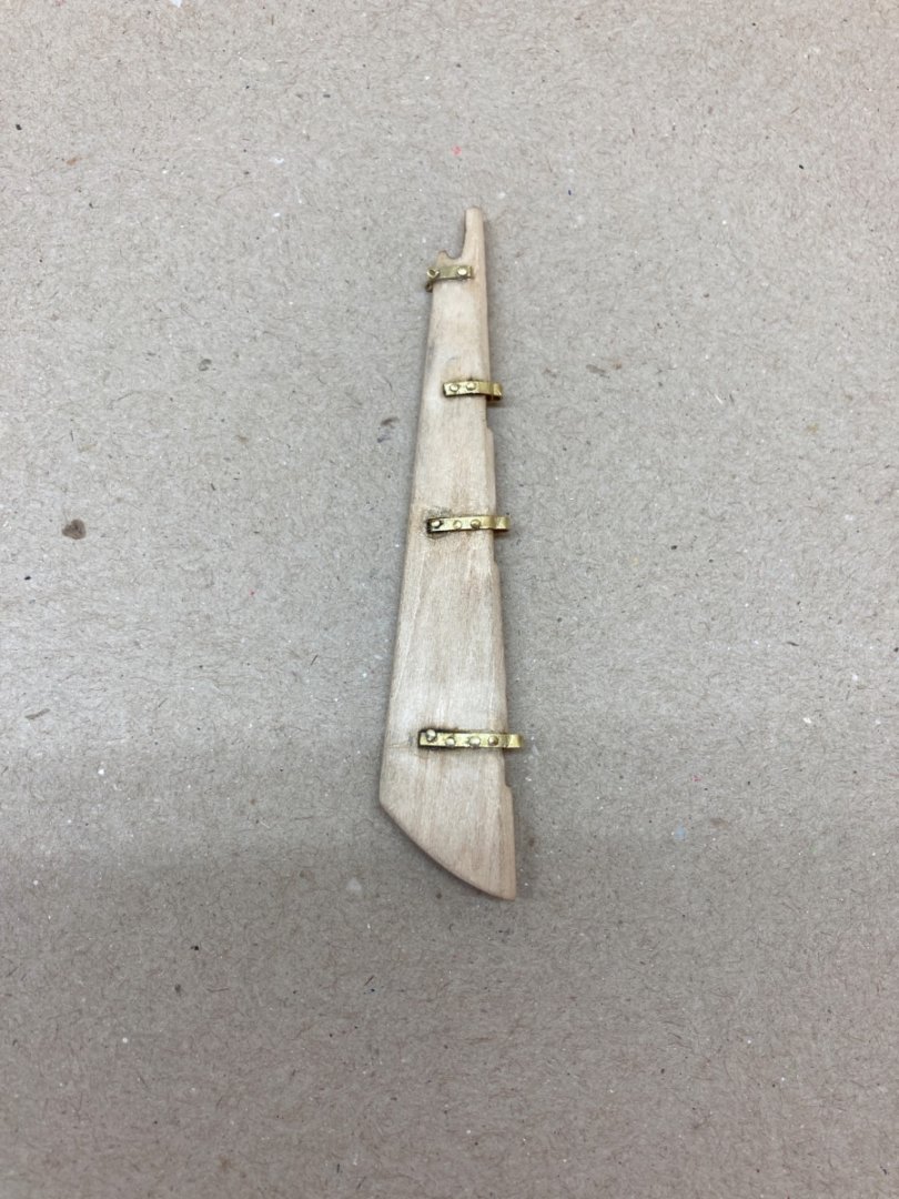
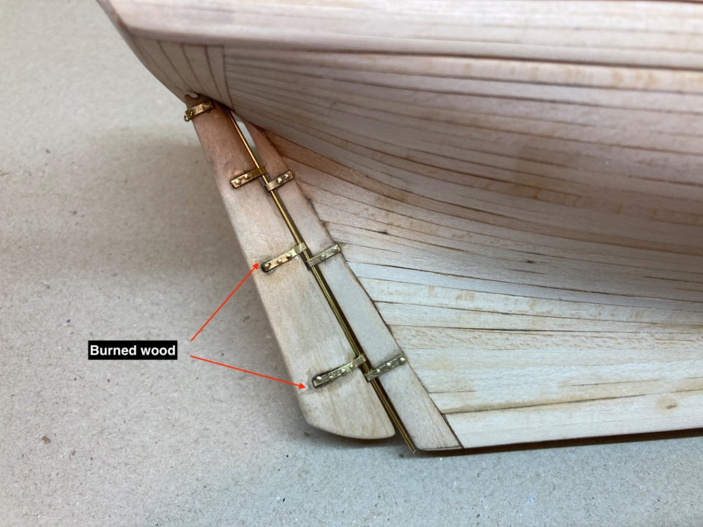
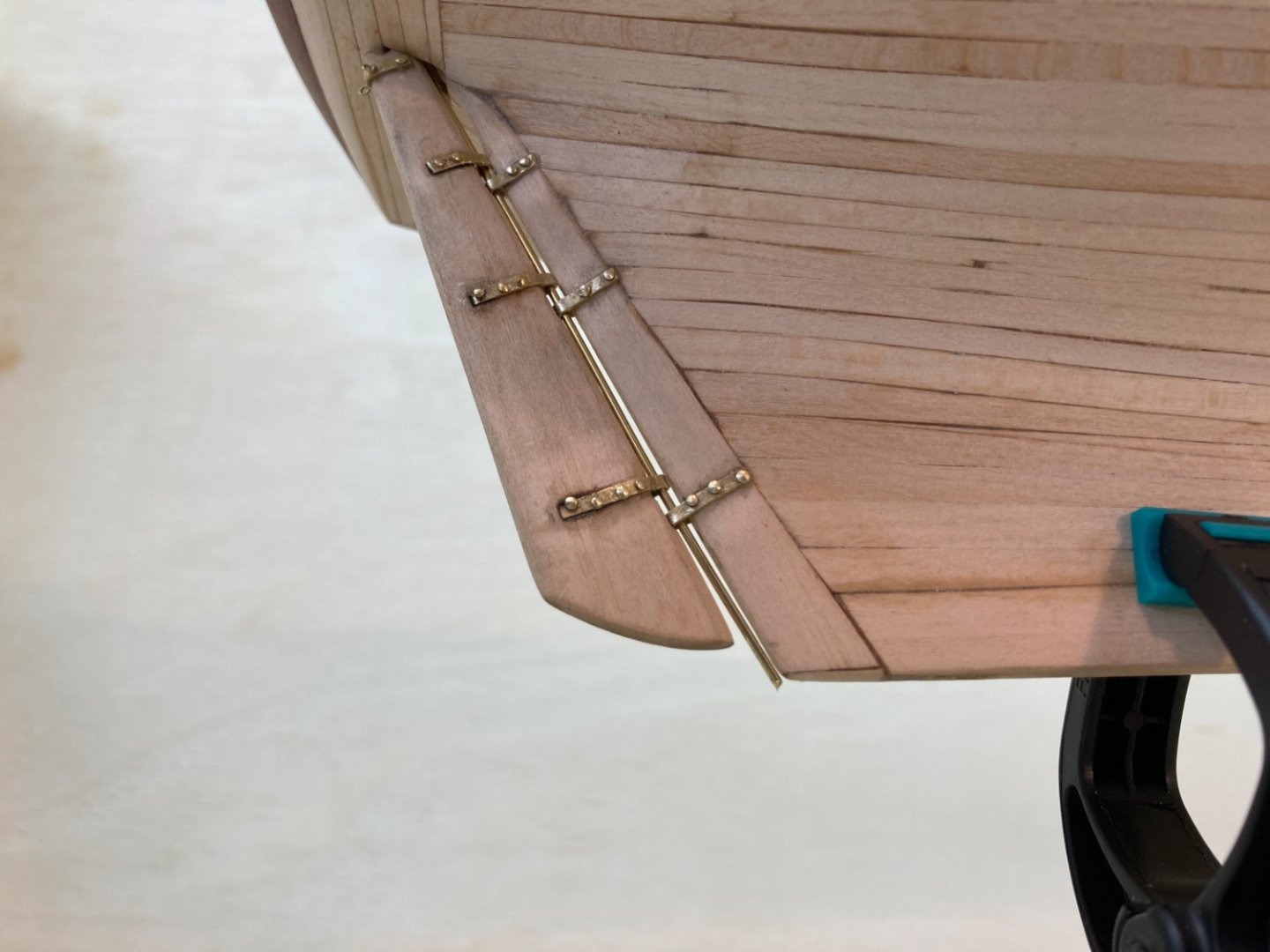
The small step before sanding sealer job ,I mentioned in the previous post , was the preparation of Pintle and Gudgeon brackets on the rudder and sternpost plus the brass bracket at the top of the rudder. The brass sheets used for this purpose were 0.008 inch (0.2 mm) thick and 1/32 inch (1.6 mm) wide and were already in kit stock. After careful location and size measurements , those brass strips were prepared and glued to their final positions. I decided to drill out the holes for nail heads after the brass brackets were glued and fixed. I used #70 drill bit with Dremel Micro handpiece. I started with the port side of the rudder and opened the holes without any complication. However on the starboard side when drilling the holes for the lower two brackets, the underlaying wood was burned. This was probably due to the increased friction and thus heat by forcing the worn-out drill bit. I should have used a new one as soon as I felt the first signs of need to increase the force of the handpiece. So I used a new drill bit for the job on sternpost which was uneventful. The initial nail heads I used on the rudder seemed a bit large and popped out, so I changed them with smaller ones ( 0.2 mm less head diameter) later. The nail heads you see in the photos below are the final ones. The brass rod connecting the rudder and sternpost is temporary and for photographing purposes only. Port side Starboard side


- 114 replies
-
- 7
-
-
- Pride of Baltimore II
- Model Shipways
- (and 1 more)
-
Now it was time to apply stain to deck planks. As I posted before I chose Antique Pine Color. I prepared 40 ml of stain and added 10 ml lacquer thinner. All areas on deck except planks were masked. For stain application I used two same size cut brushes about 2 cm cut edge. While applying the stain mixture by one brush , I used the other dry one immediately after it and removed any stain residue. The brush actions were paralel to the planks on all deck except the narrow areas where only vertical -to -plank action was possible.I waited 24 hours after the first coat and applied the second coat in the same manner the next day. Here is a photo of the deck as reminder before the photos taken after stain apllication. Photos after stain application. Once the deck stain was completely dry ,I planned to start the sanding sealer job on both deck and hull. But there is one small step before it which I will post tomorrow.


- 114 replies
-
- 6
-
-
- Pride of Baltimore II
- Model Shipways
- (and 1 more)
-
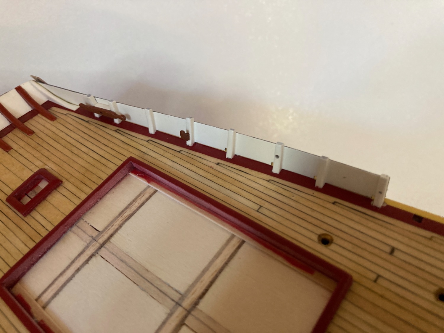
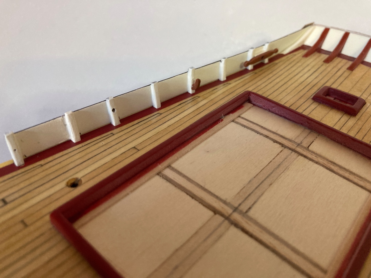
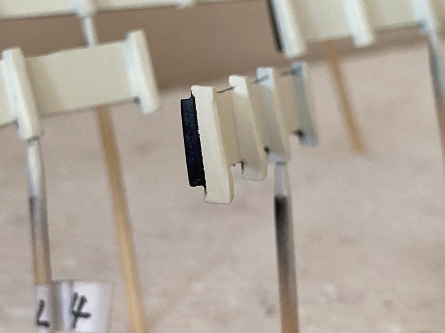
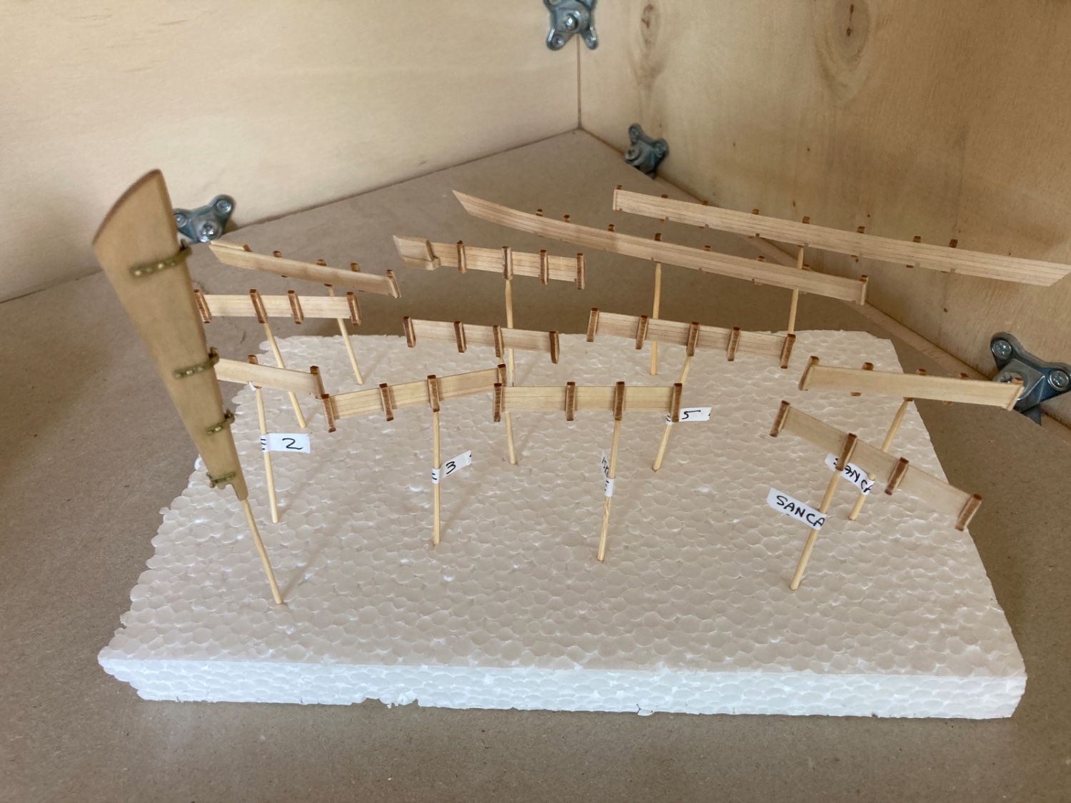
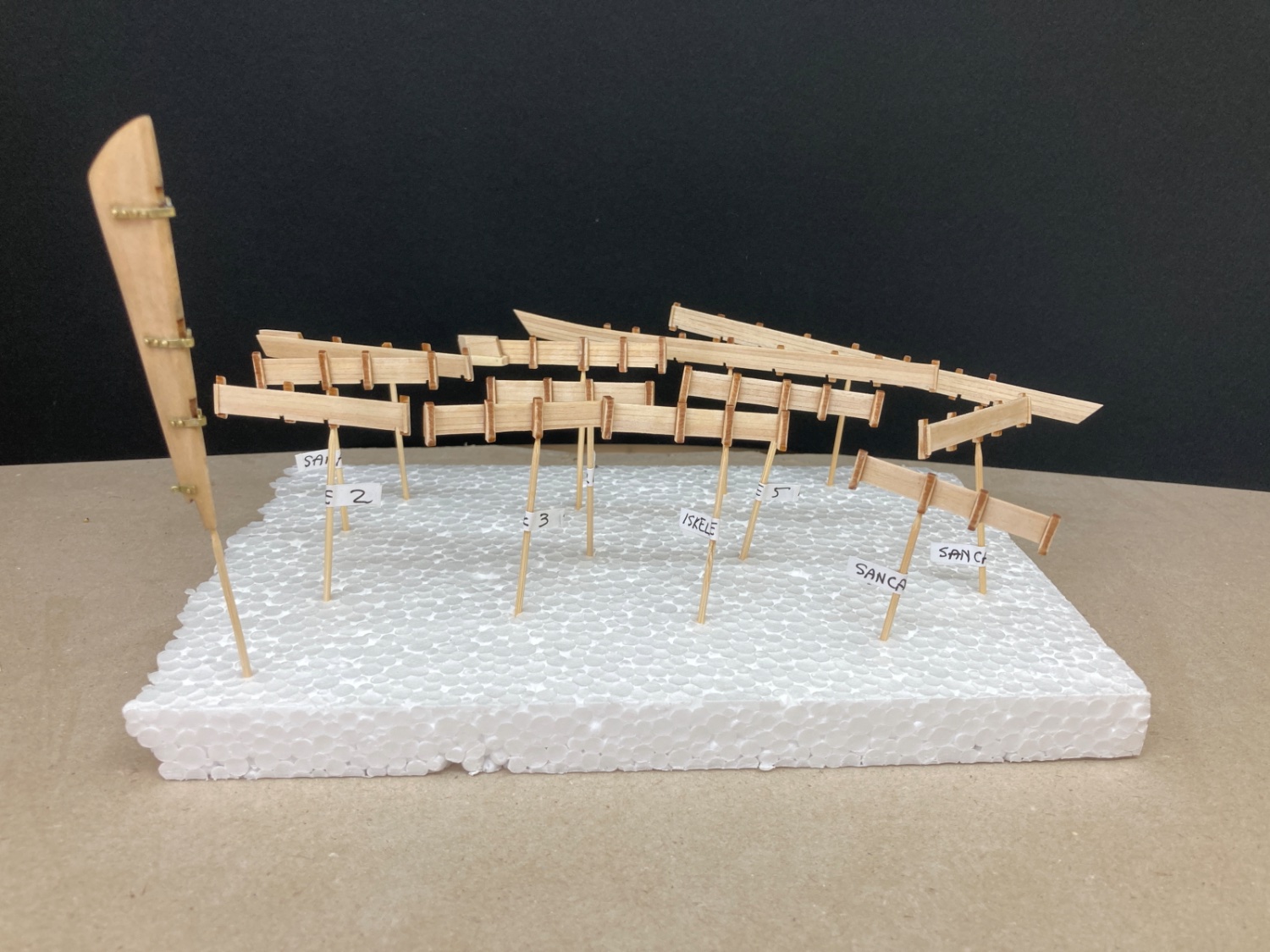
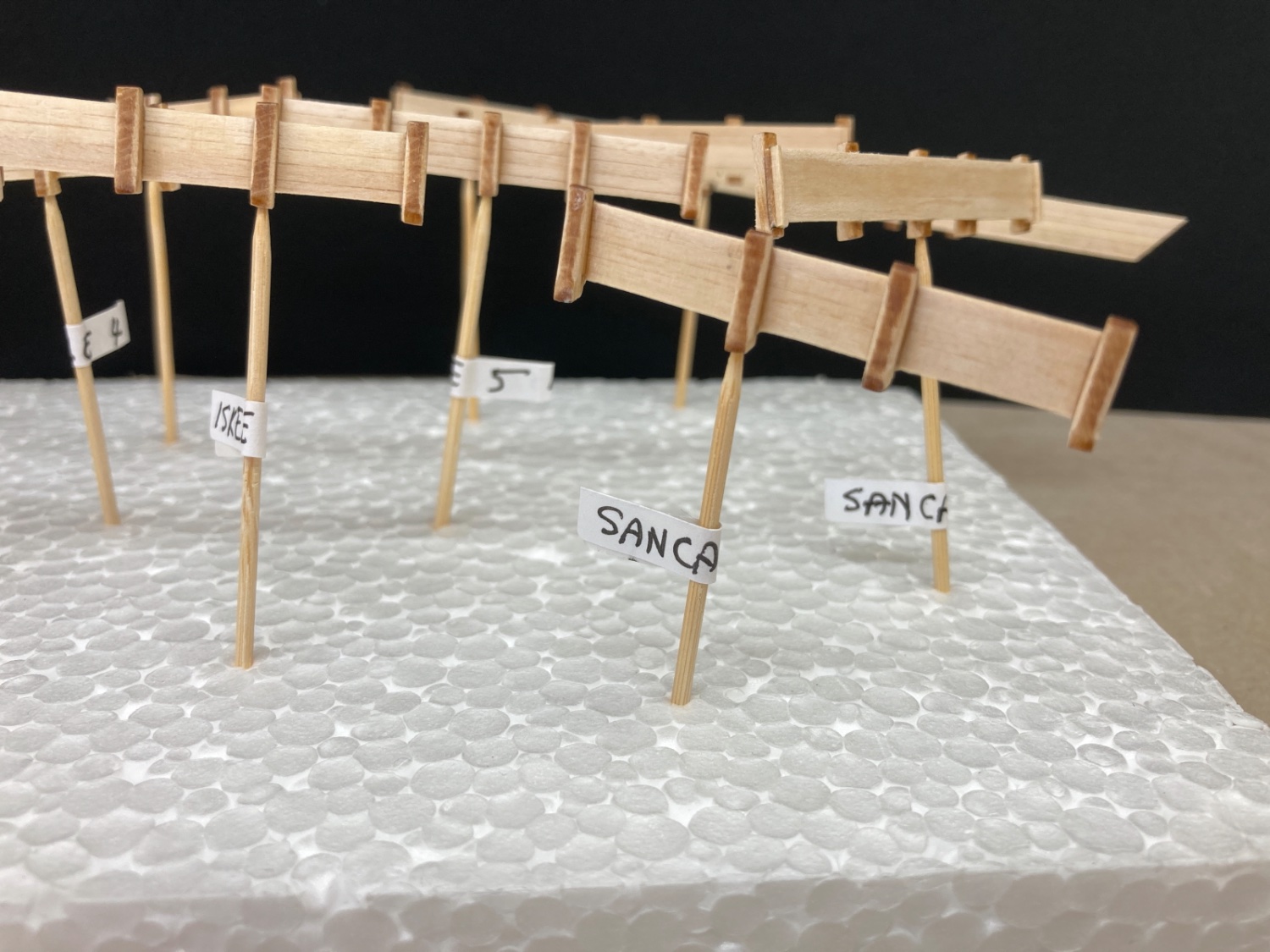
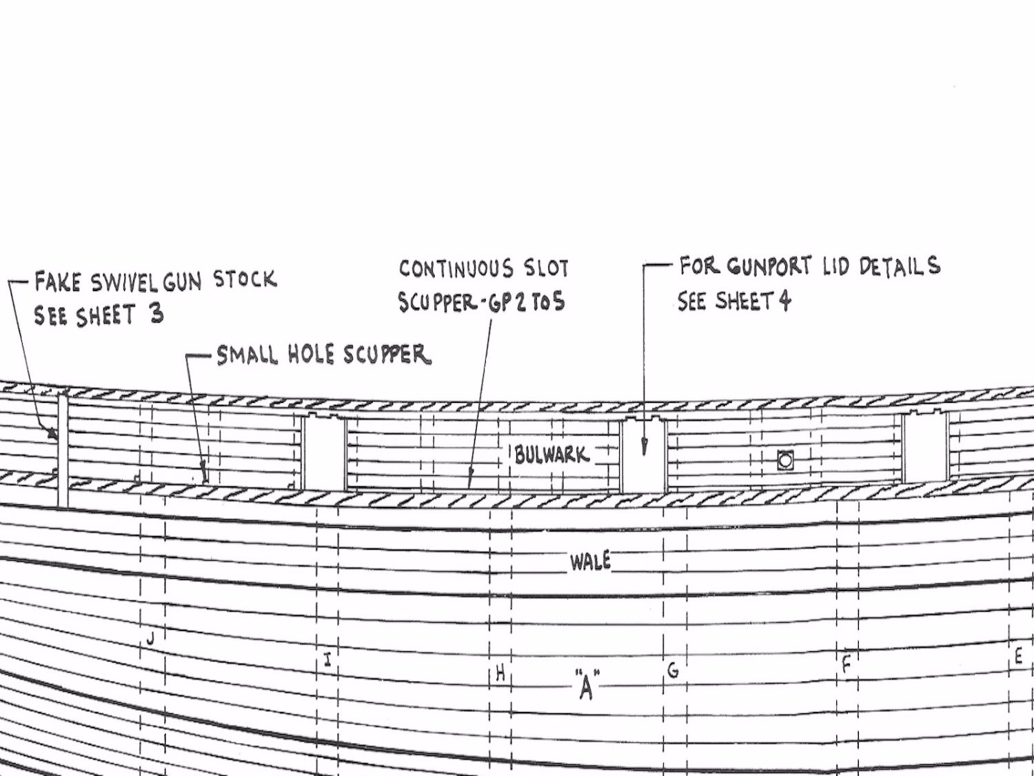
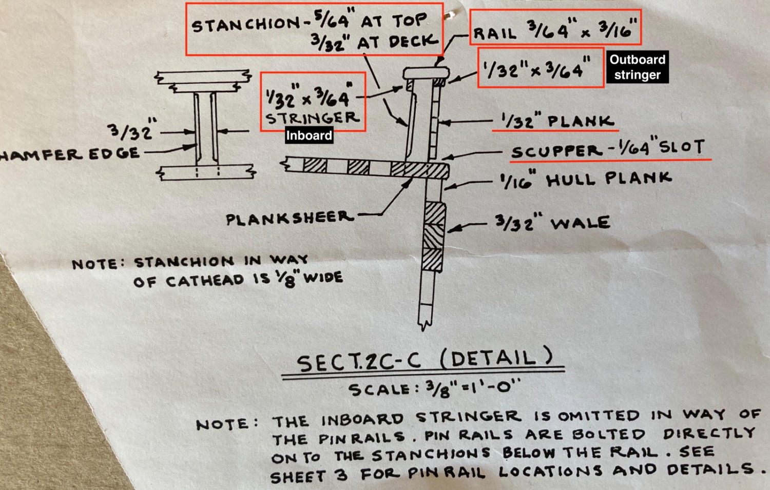
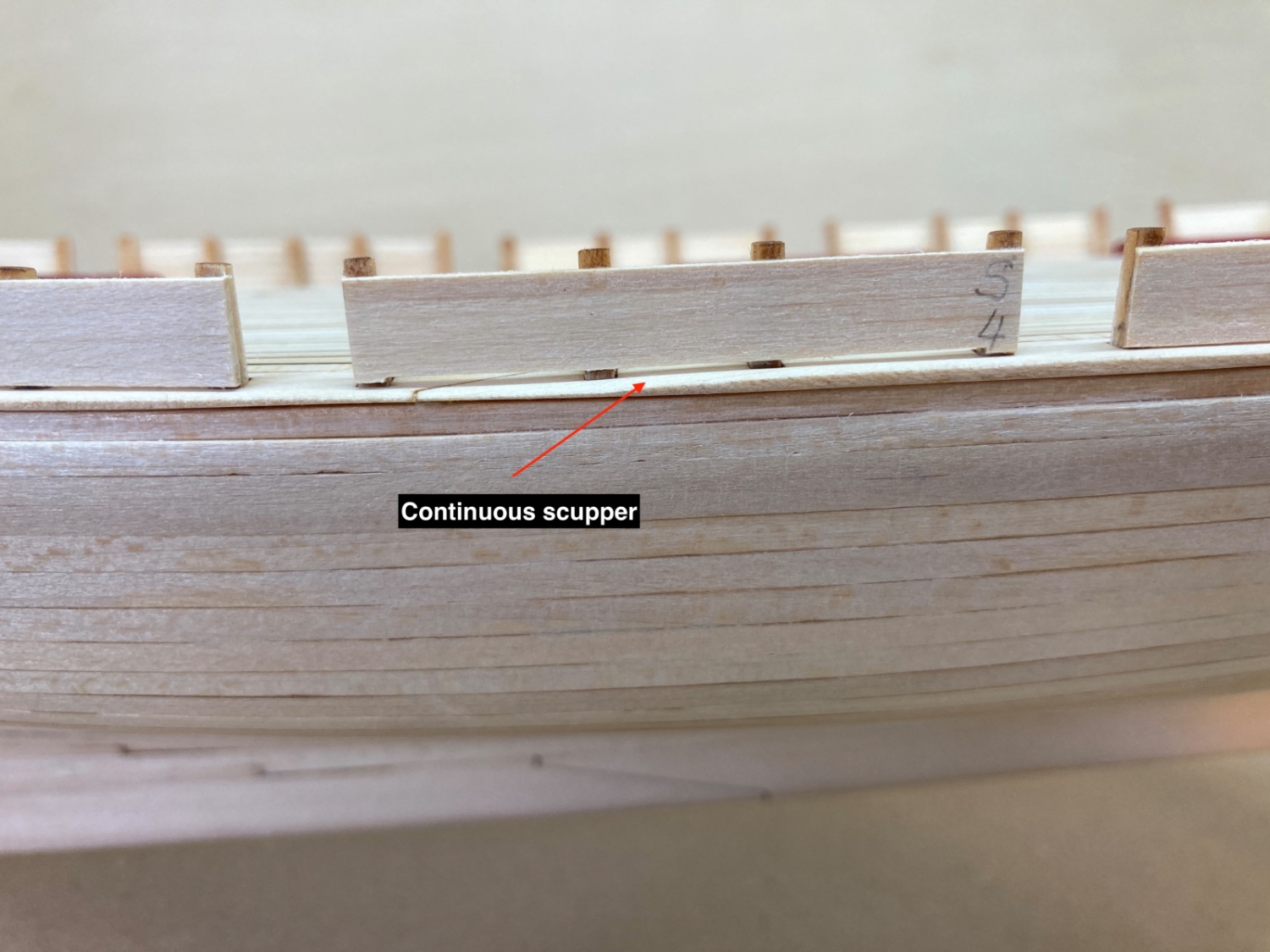
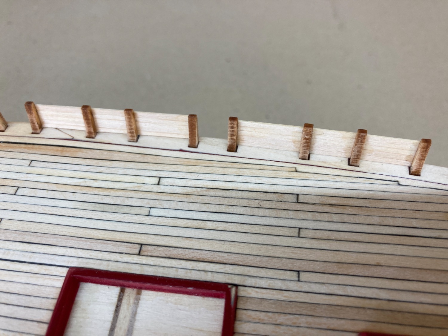
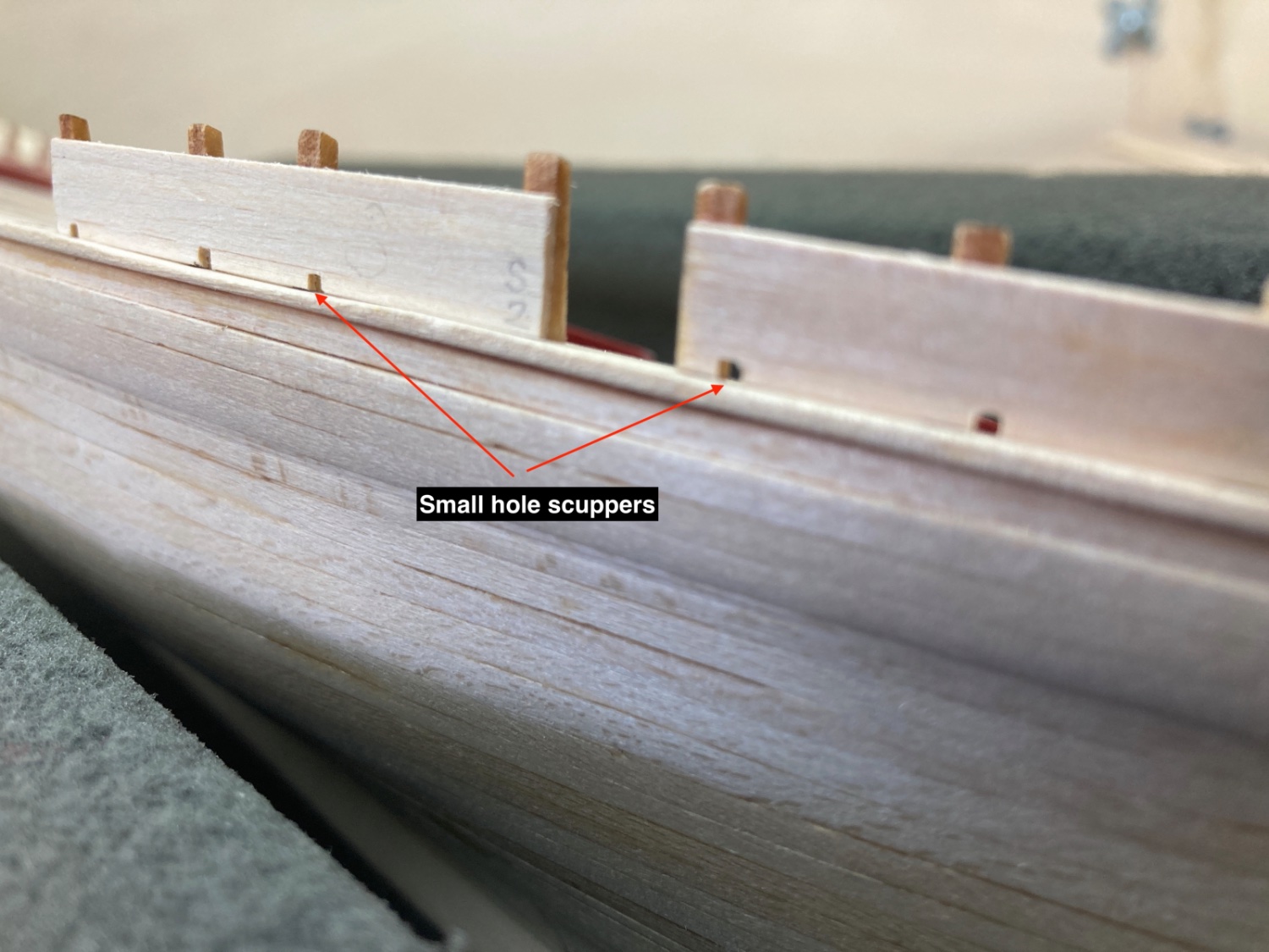
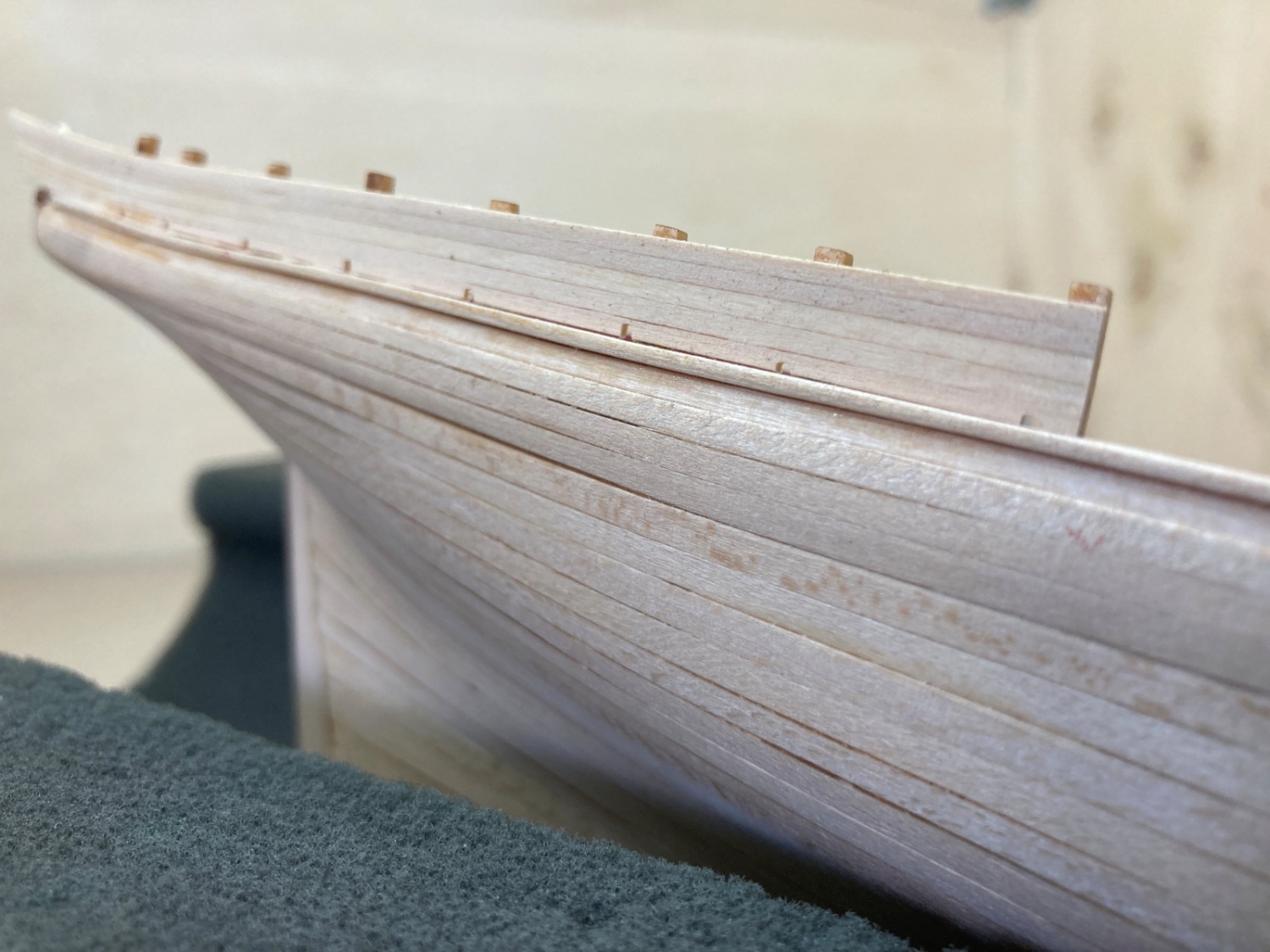
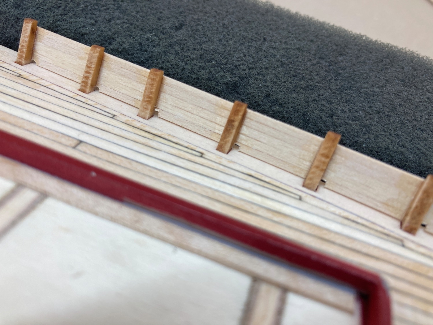
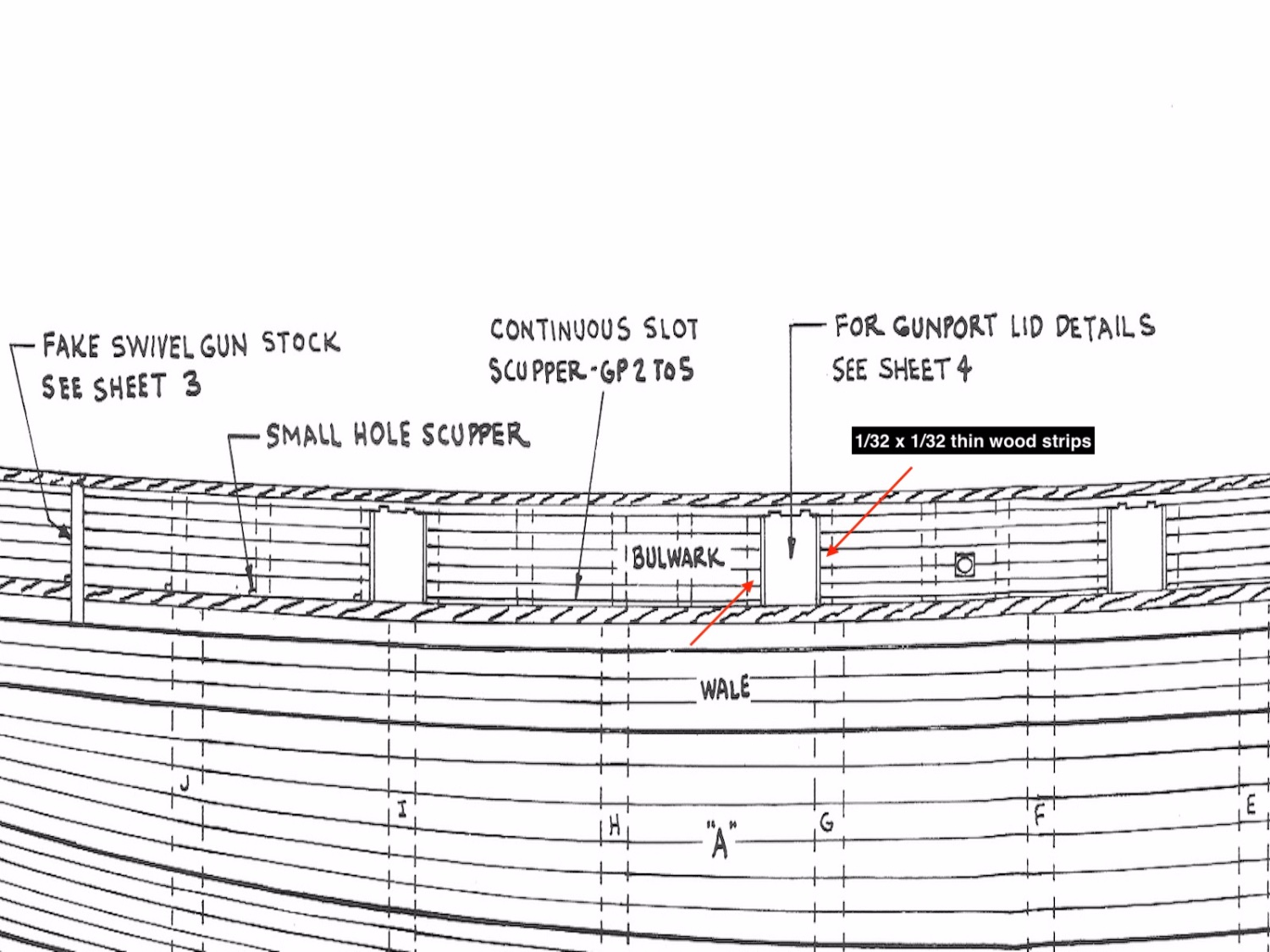
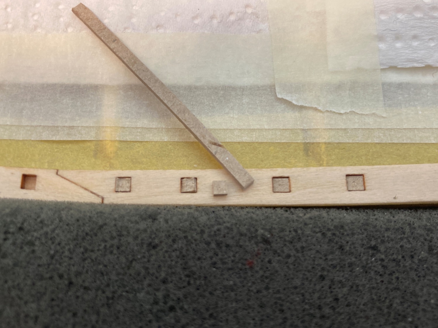
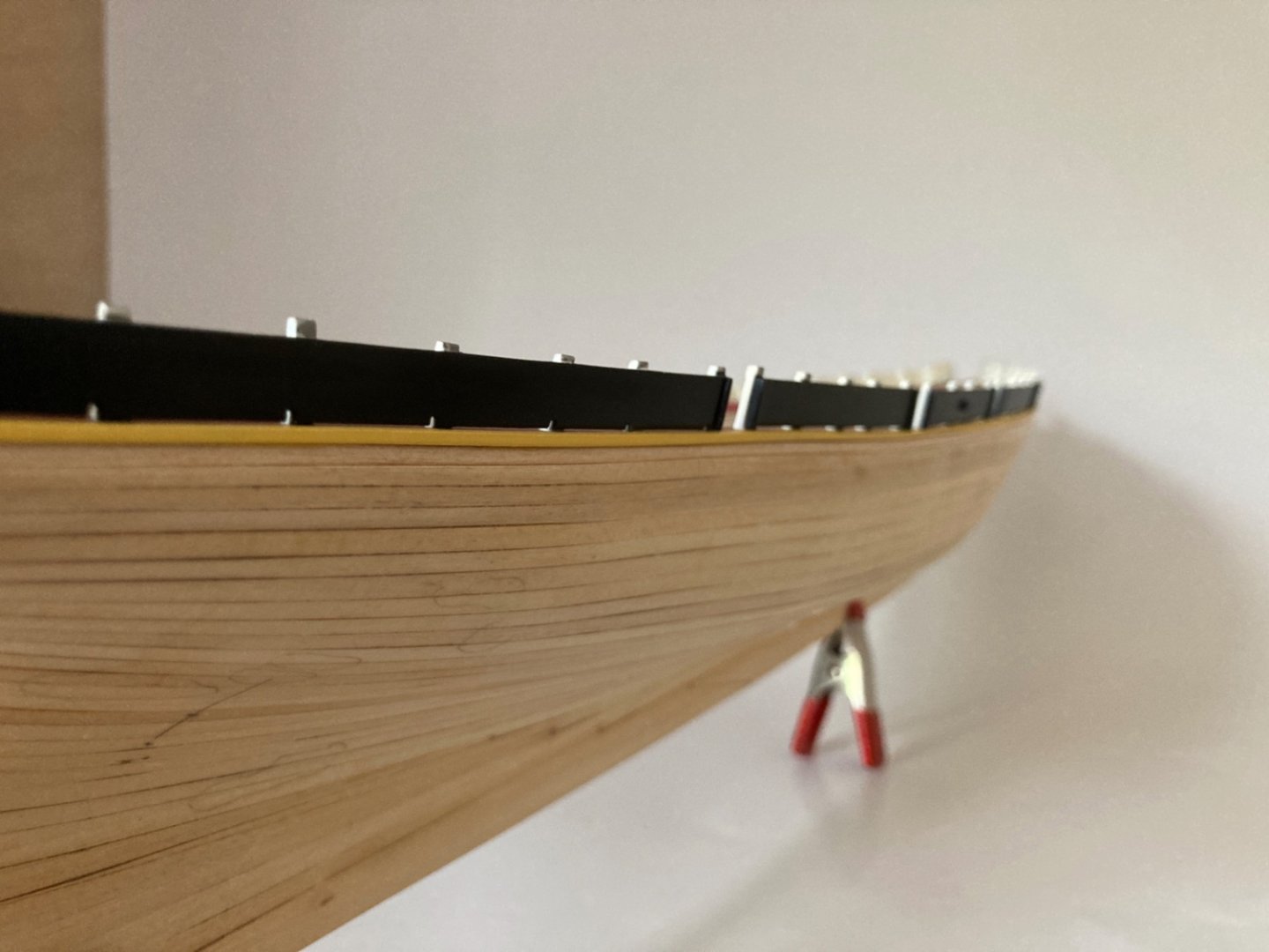
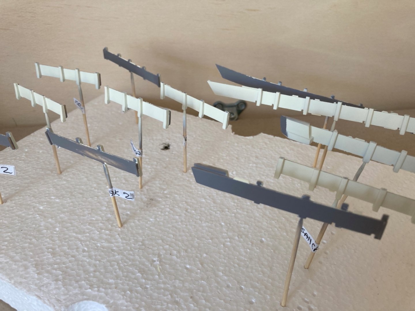
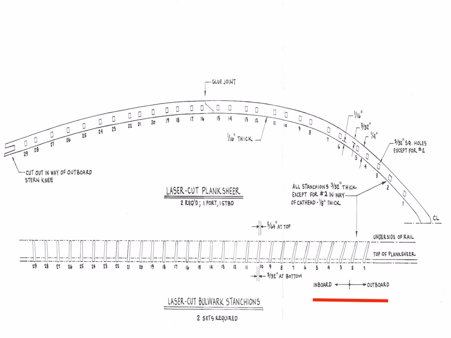
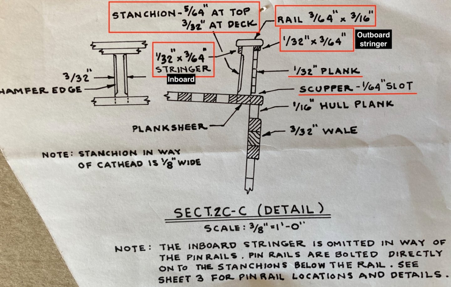
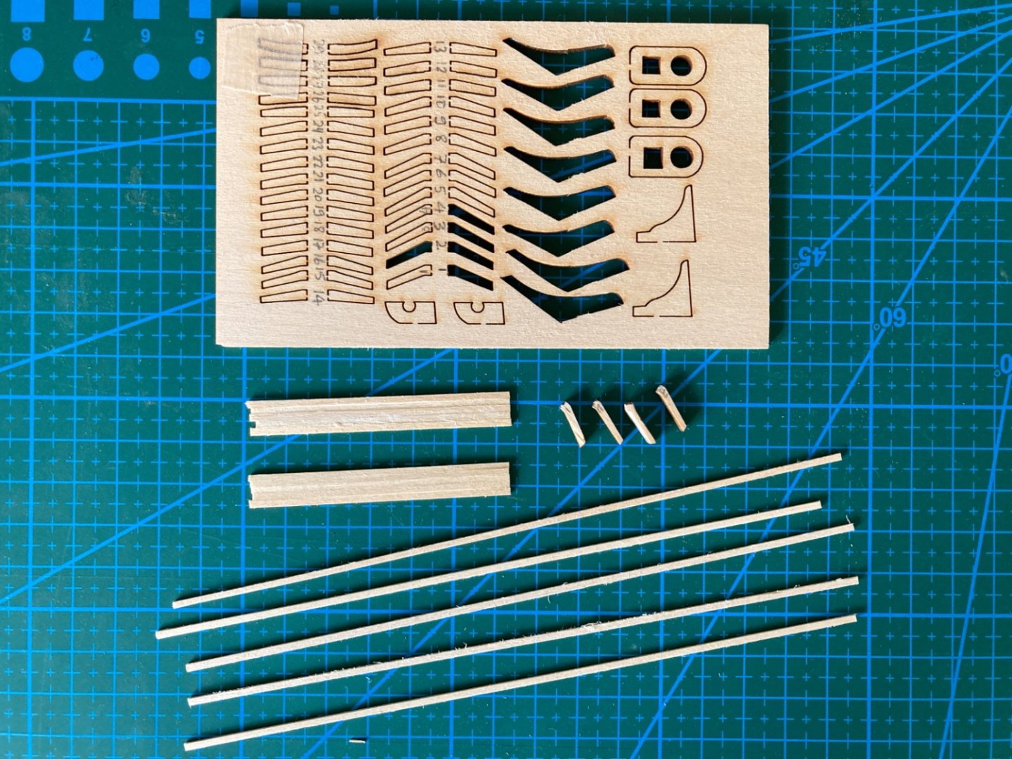
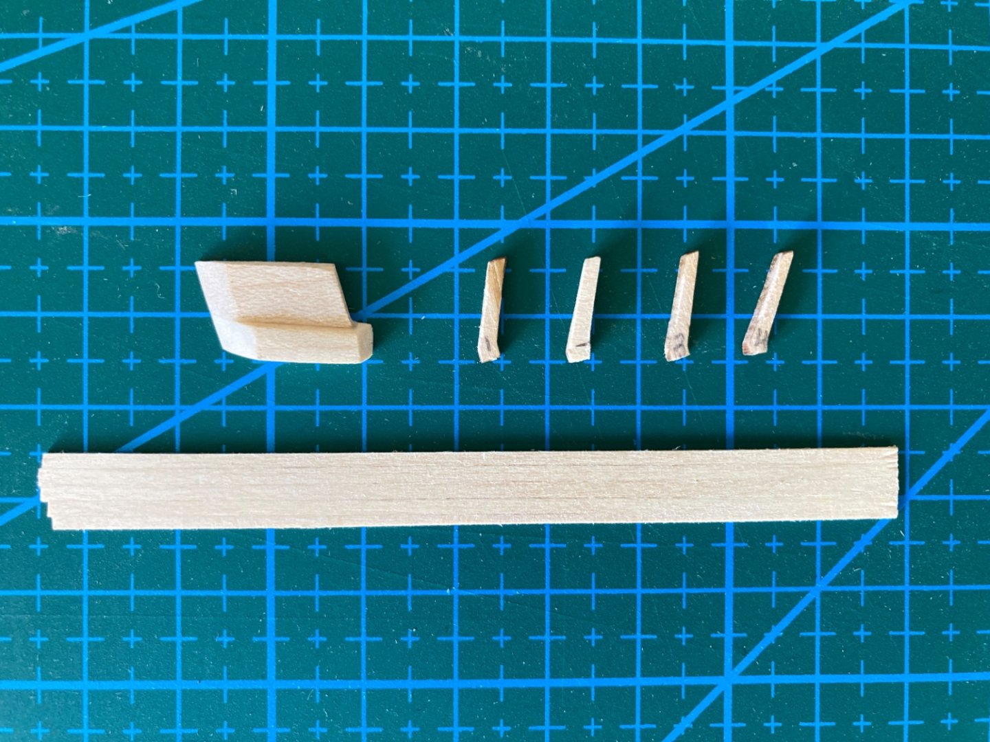
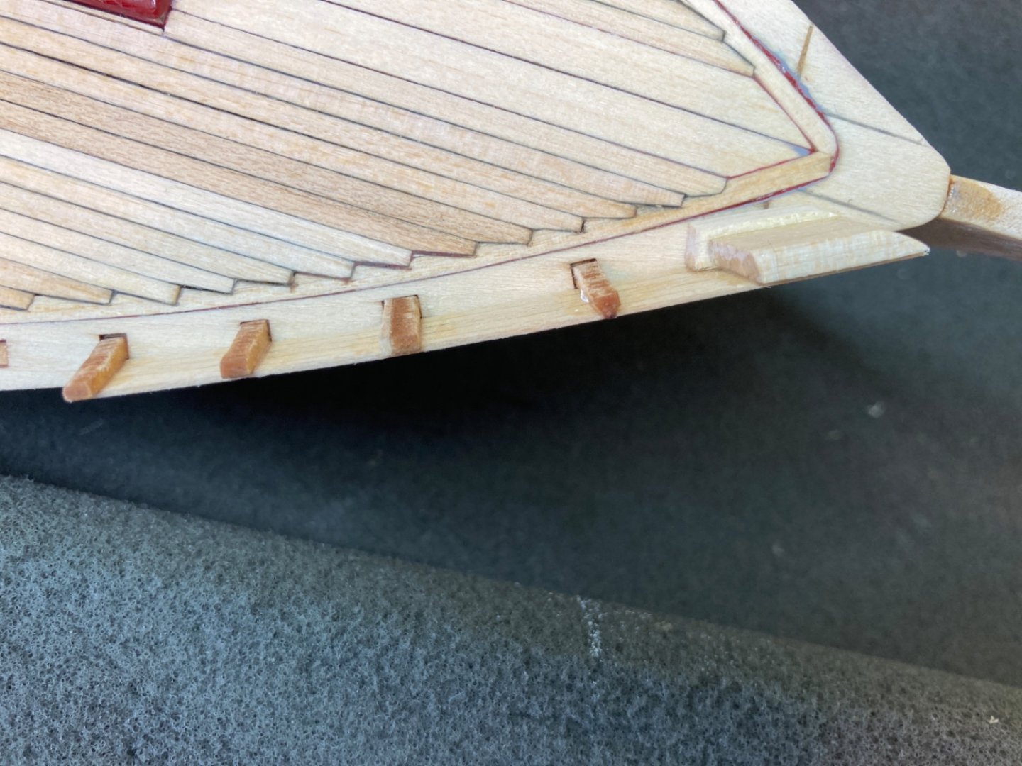
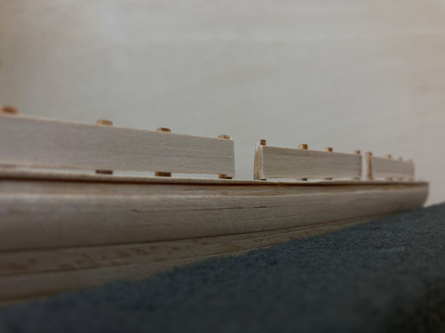
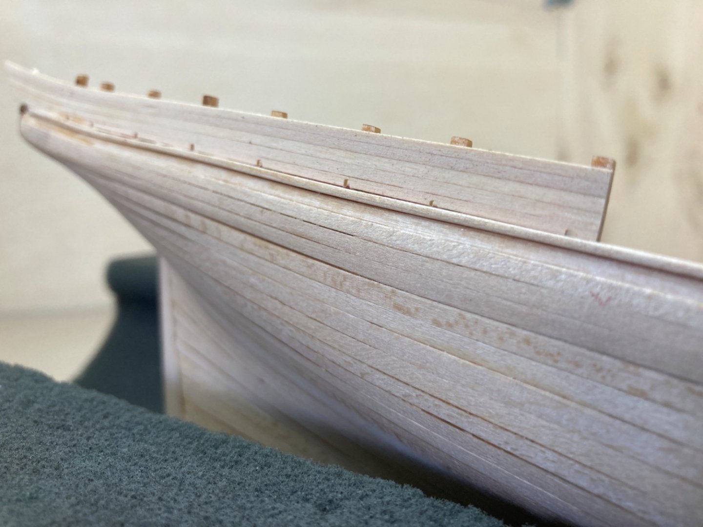
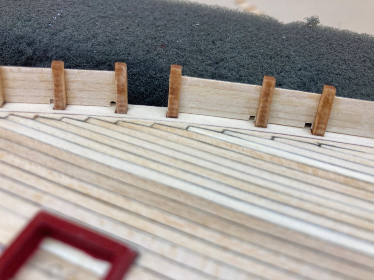
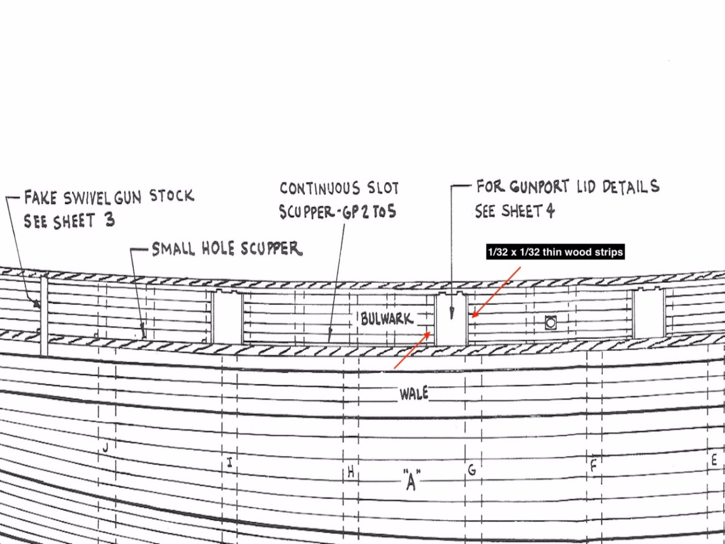
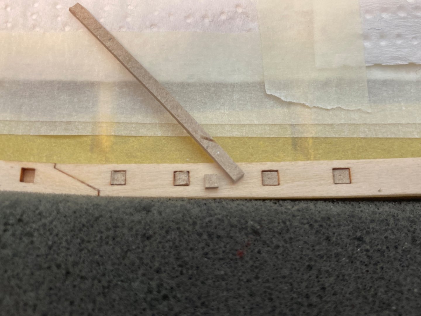
Although the installation of the bulwark stachions and later planking of them was subject to debate (whether to build on the model or build outside of the model and later install) between modelers, I think it was a quick, easy and logical decision for me to built and paint them outside of the model , section by section as their special locations allow you to do so and then install them on the model later. I felt I would be unable to paint them sharp and nicely had I builded them on the model. I thought it would be very hard even to accomplish a healthy build and adequate sanding let alone painting. Bulwarks were made of 29 stachions on each side. The shape and position of almost each stachion is different and special attention must be shown when installing them. There are 5 rows of 1/32 x 1/16 inch ( 0.8 x 1.6 mm) basswood strips on their outboard sides. Bulwarks are interrupted at the 5 gunpoints on each side. This makes 6 sections of bulwarks on each side. At the top of the outboard planks there is a continuous plank (outboard stringer) 1/32 x 3/64 inch ( 0.8 x 1.2 mm) in size. Please note that the 1/32 inch (0.8 mm) edge of this stringer sits on the stachions. On the inboard side, also at the top, there is an inboard stringer. This stringer is also the same size like the outboard one but its 3/64 inch (1.2 mm) edge it sits on stachions. The inboard stringer however is not continuous like the outboard one and interrupts at the two pin rails which were attached to stachions and underface of rail. Some bulwark sections have continuous spaces between them and plank sheers they sit on, called scuppers. Others have small hole scuppers. The photos taken from the plans show the position and sequence of the stachions, bulwark planking characteristics, outboard and inboard stringers and scuppers. First I numbered each stachion on the wood sheet while they are attached to it. I only removed the ones that were to be used on each bulwark section build. Also I glued and prepared the 5 rows of outboard planks before attaching the stachions to them. Starting from the bow I numbered the sections like S1, S2, S3,S4,S5 and S6 on starboard side and as P1,P2,P3,P4,P5 and P6 on port side. Sections 1 , 2 and 6 have small hole scuppers and sections 3, 4 and 5 have continuous scuppers. The creation of those scuppers were done after the preparation of all bulwark sections were finished. Bulwark planks of first section attach to the hawse timbers all the way to their fore edge. I started with bulwark S1. Then P1 section was prepared Then all other sections were prepared in the same manner. After checking every bulwark section from several angles the small hole scuppers were opened and continuous scuppers were cut out. Please note that the bulwark sections were only dry fitted and not installed yet and they were put aside after sanding with 400 grit paper waiting to be painted and their detailed structures to be prepared. Now it was time to apply stain to the deck planks. Edit done later : There are 1/32x1/32 inch (0.8x0.8 mm) thin wood strips placed on bulwarks vertically at gun port sides of them. Those were prepared from kit stock. However is was a good idea to order backups from that size as they would be used on several places during build stages later. Those strips are marked with red arrows on the photos below.


- 114 replies
-
- 4
-
-
- Pride of Baltimore II
- Model Shipways
- (and 1 more)
-
Thanks a lot Yves…
-
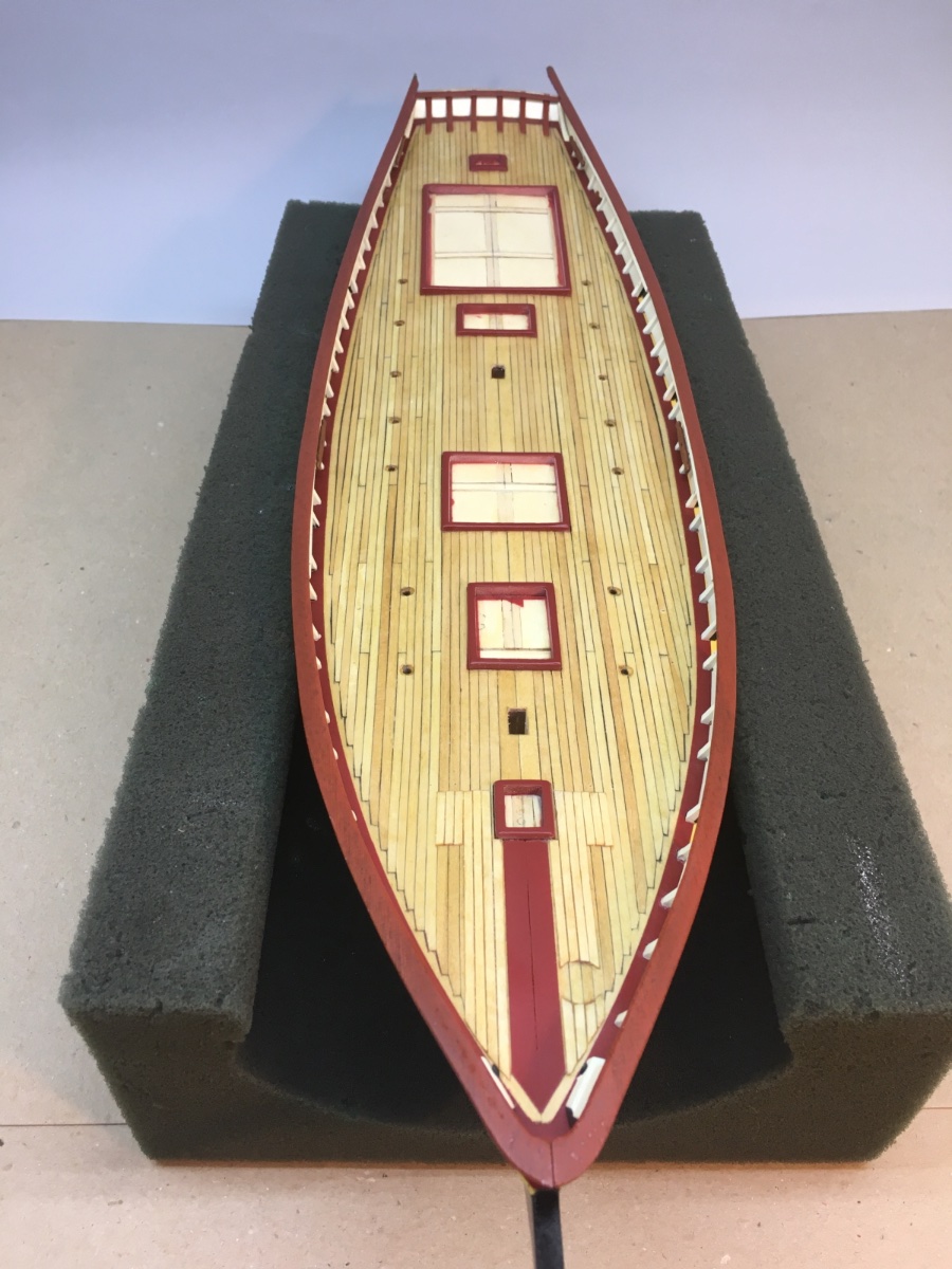
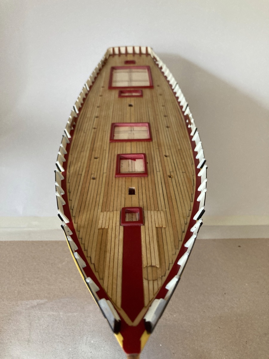
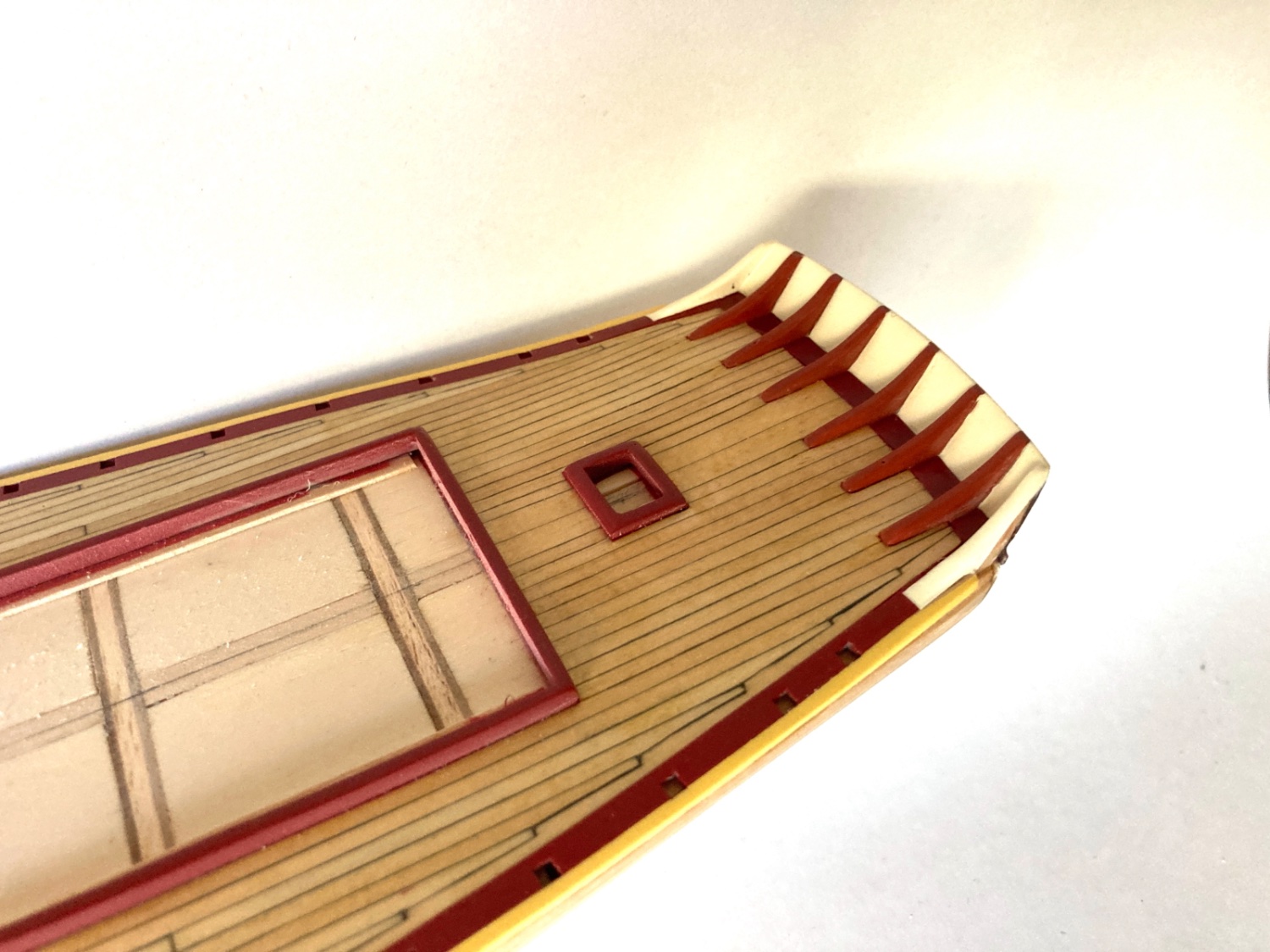
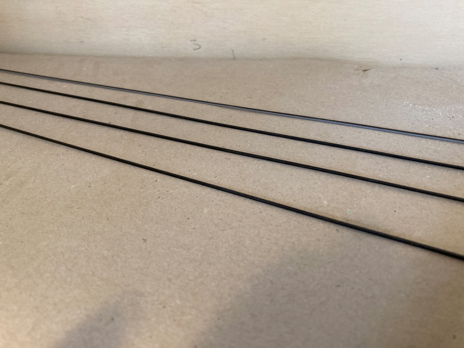
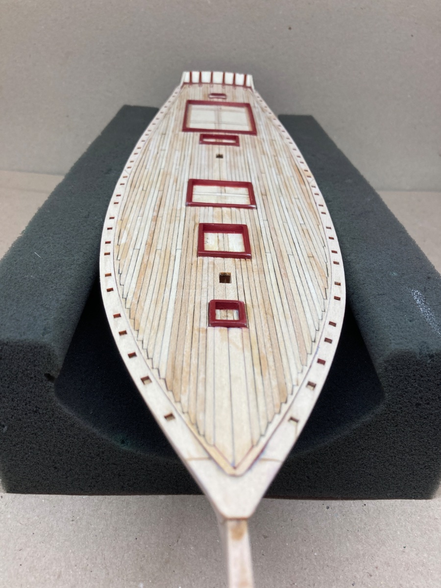
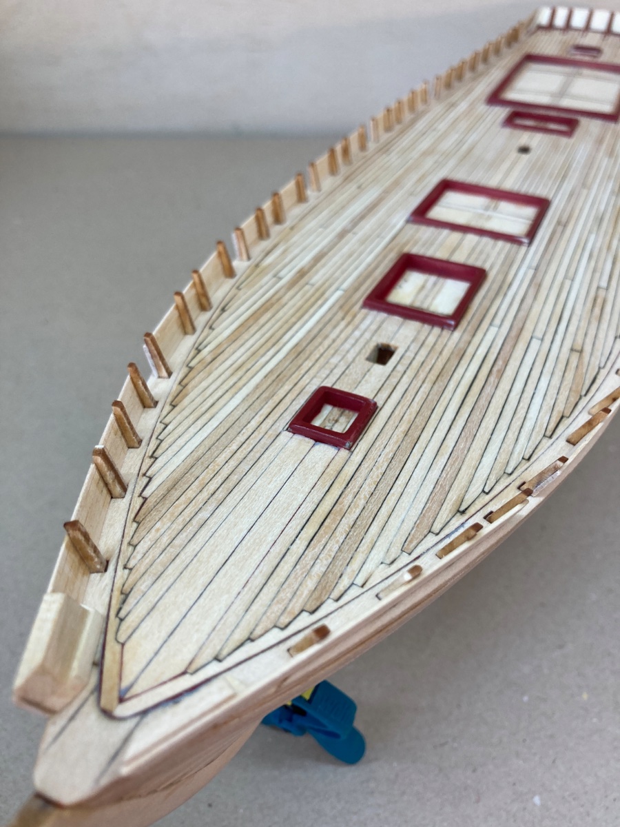
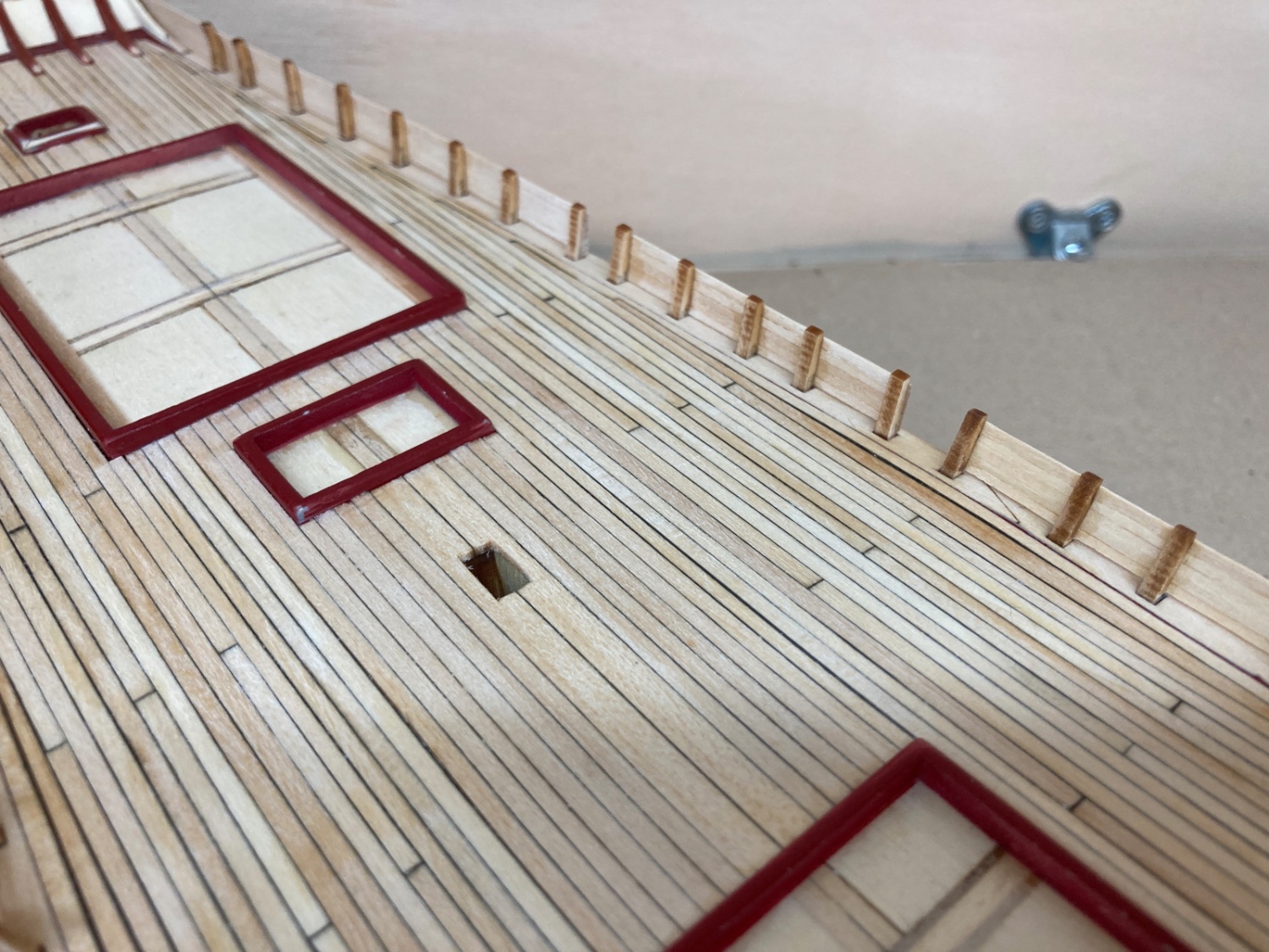
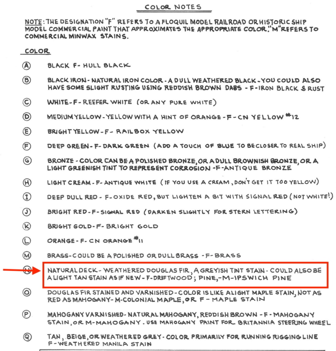
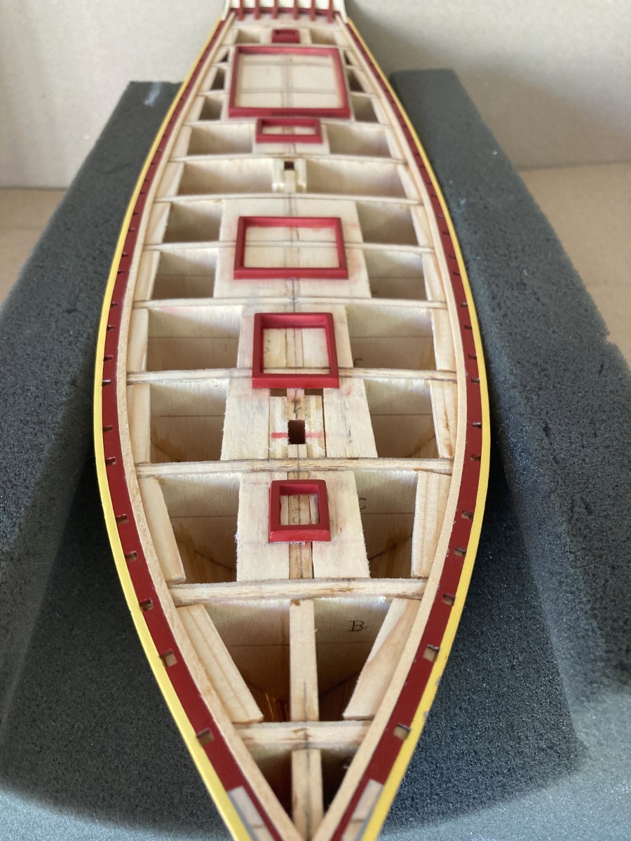
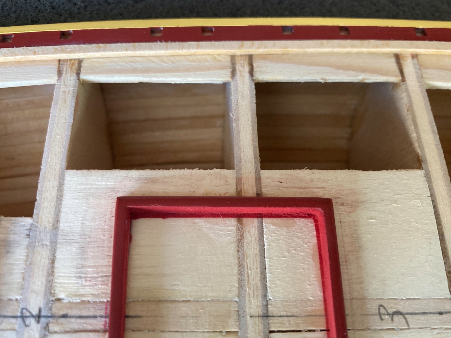
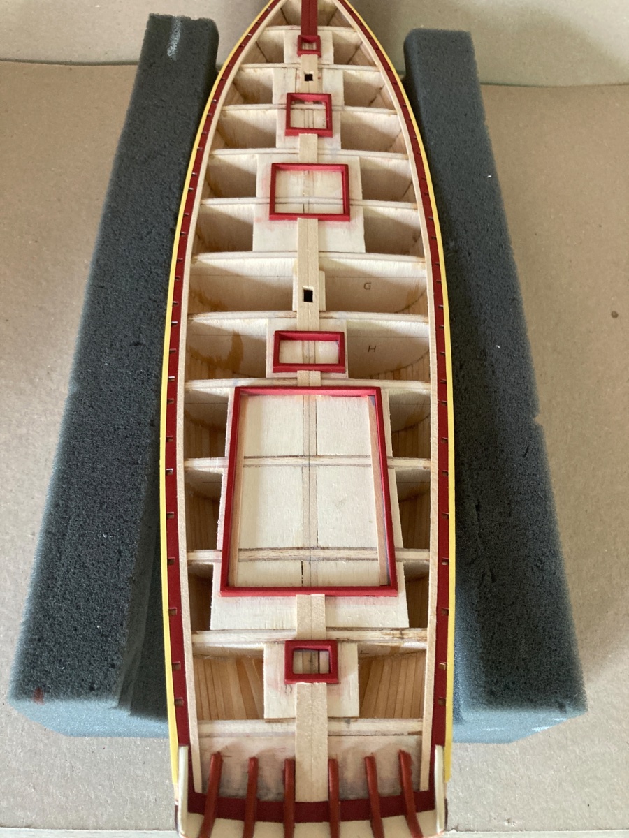
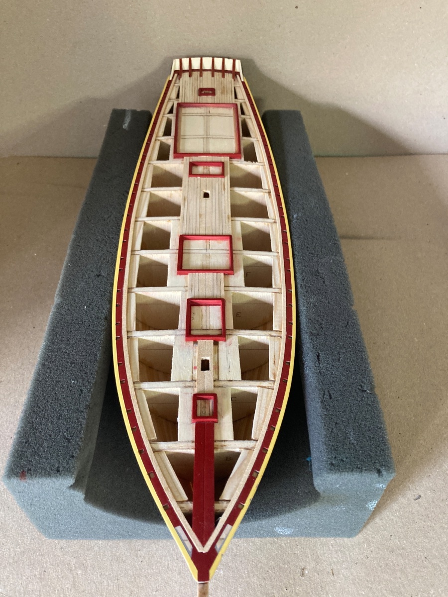
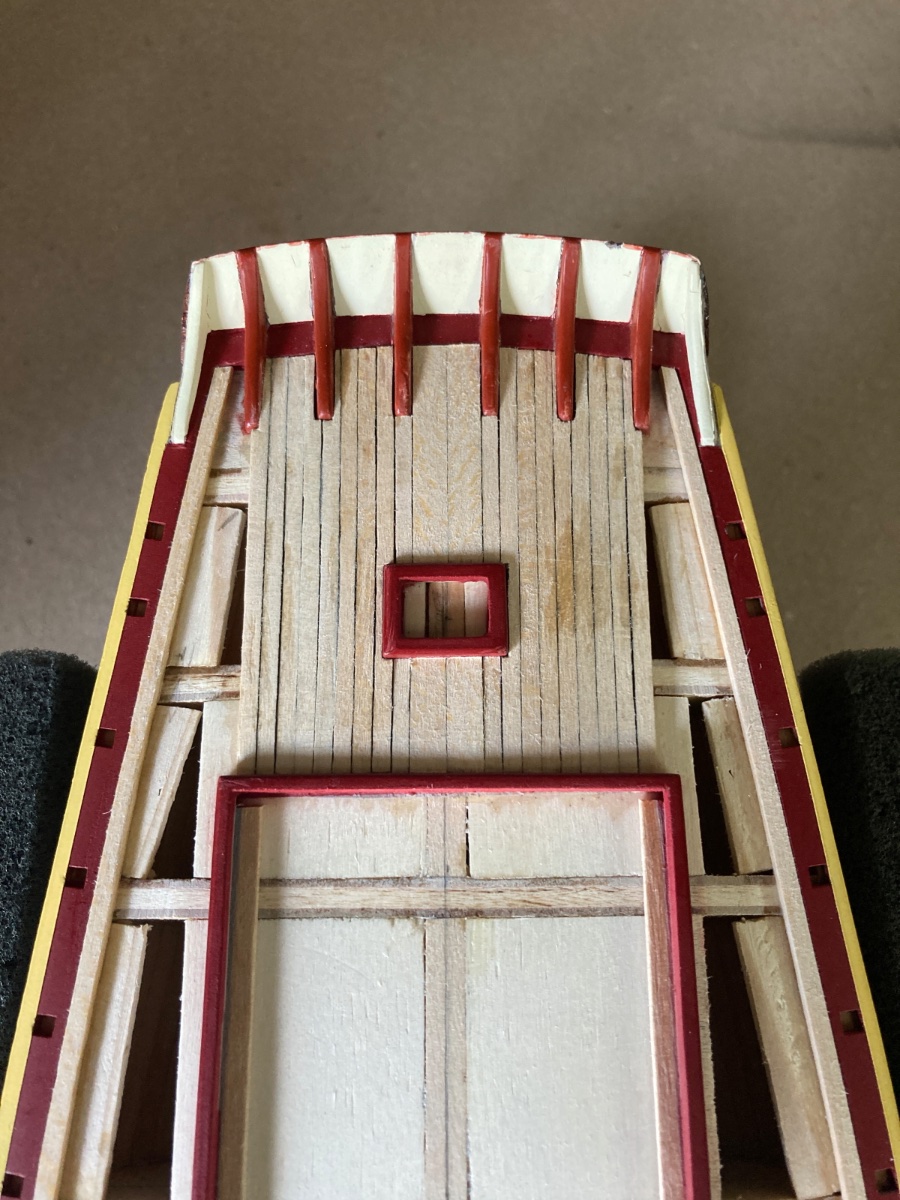
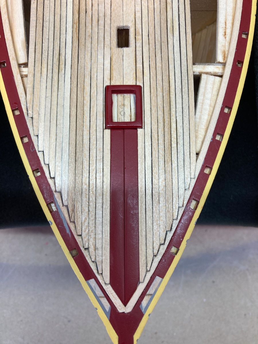
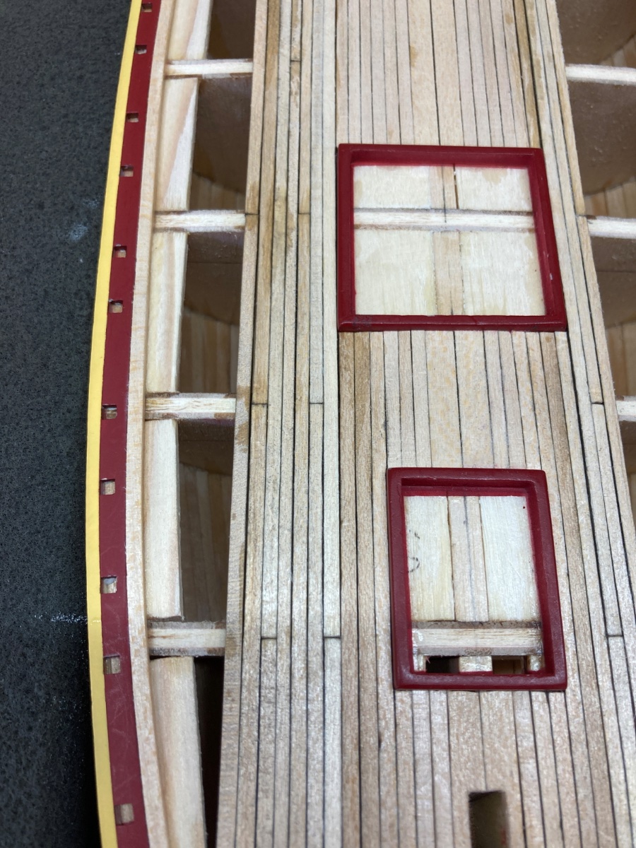
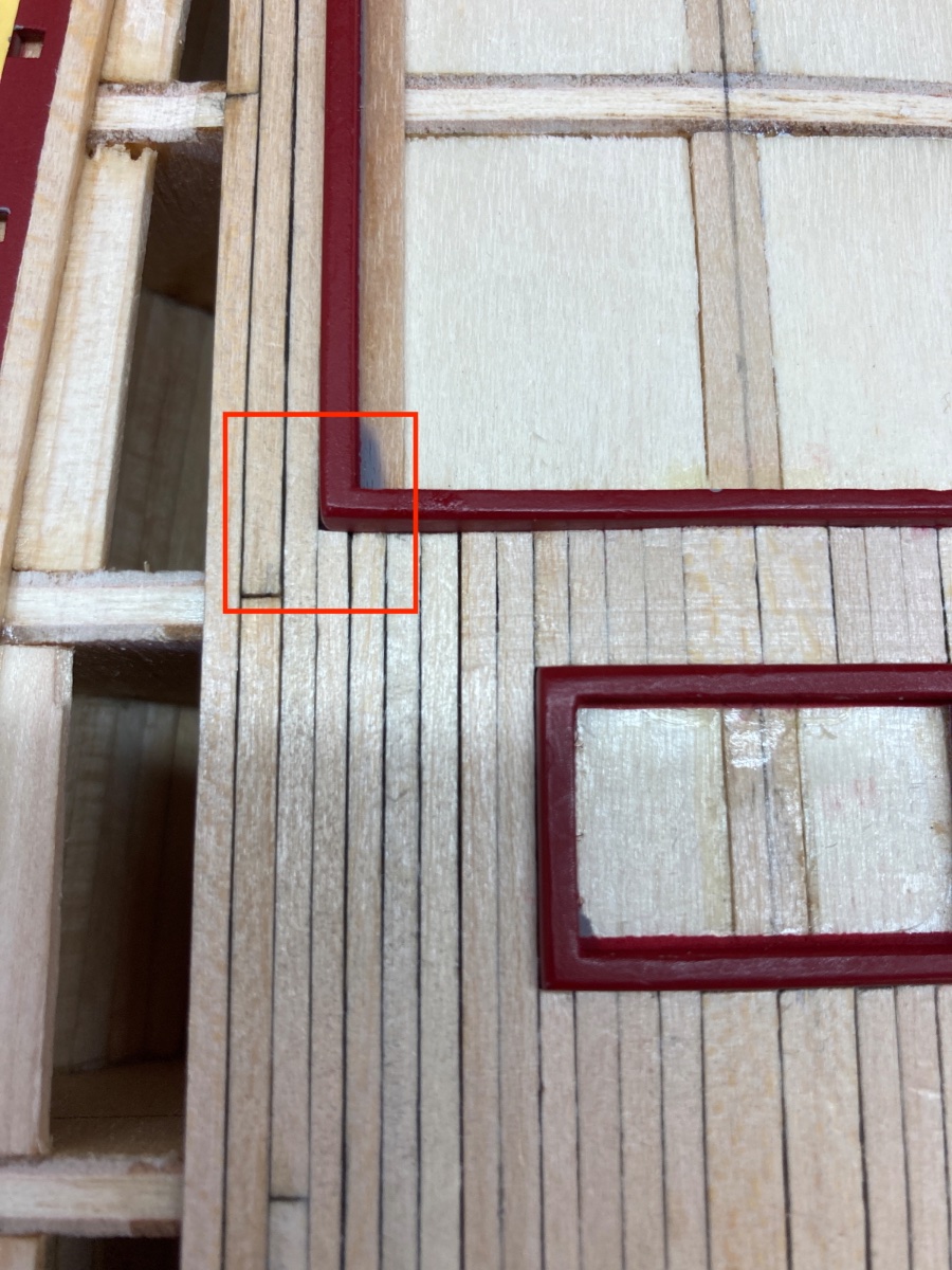
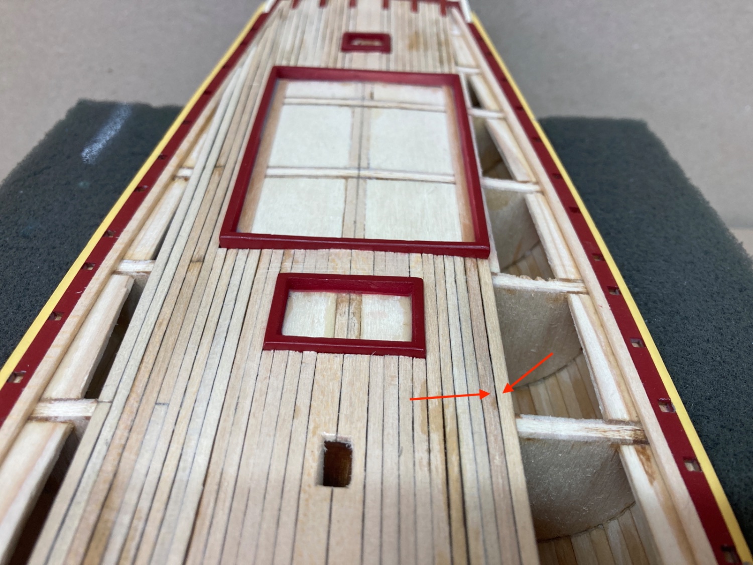
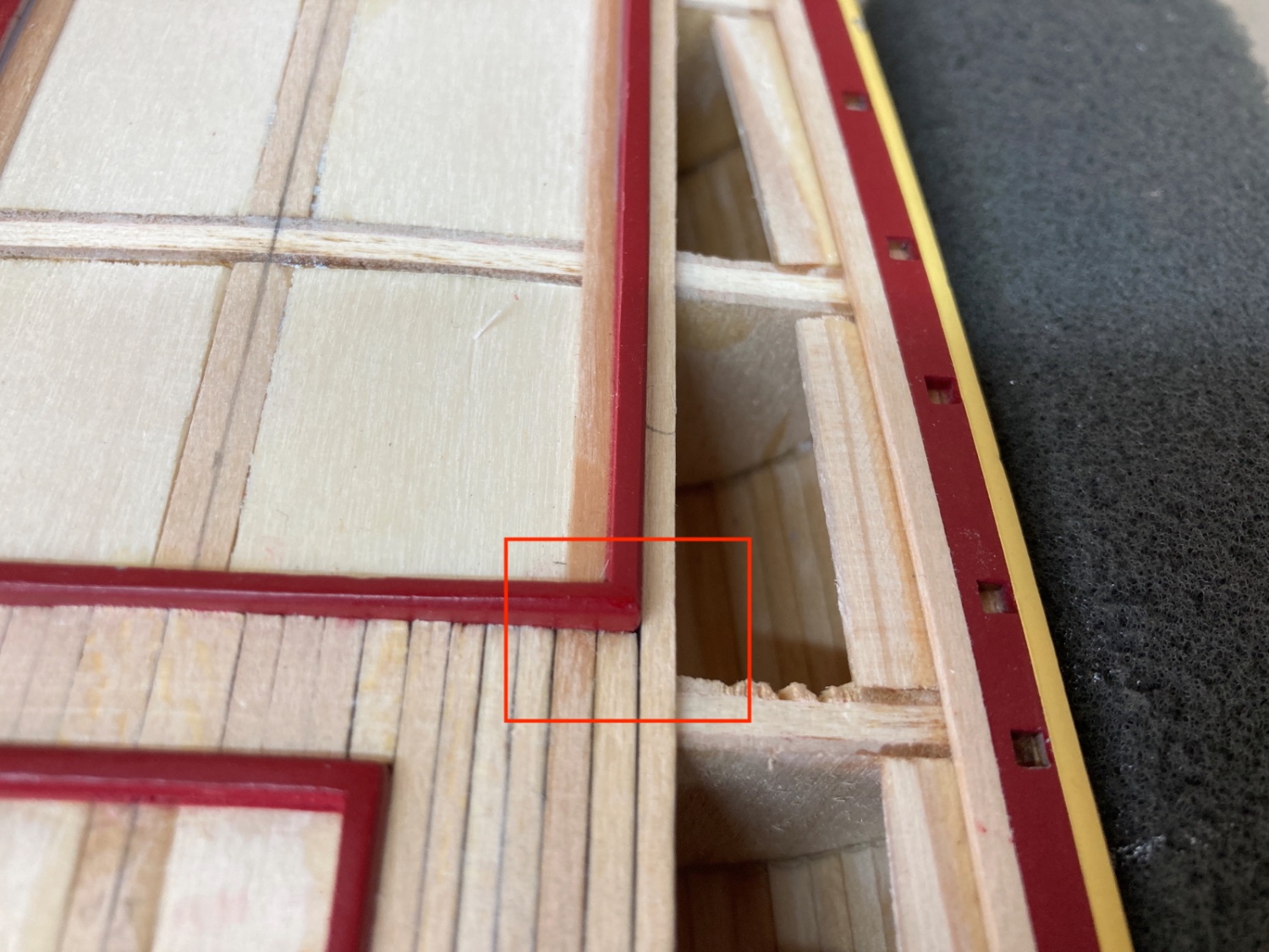
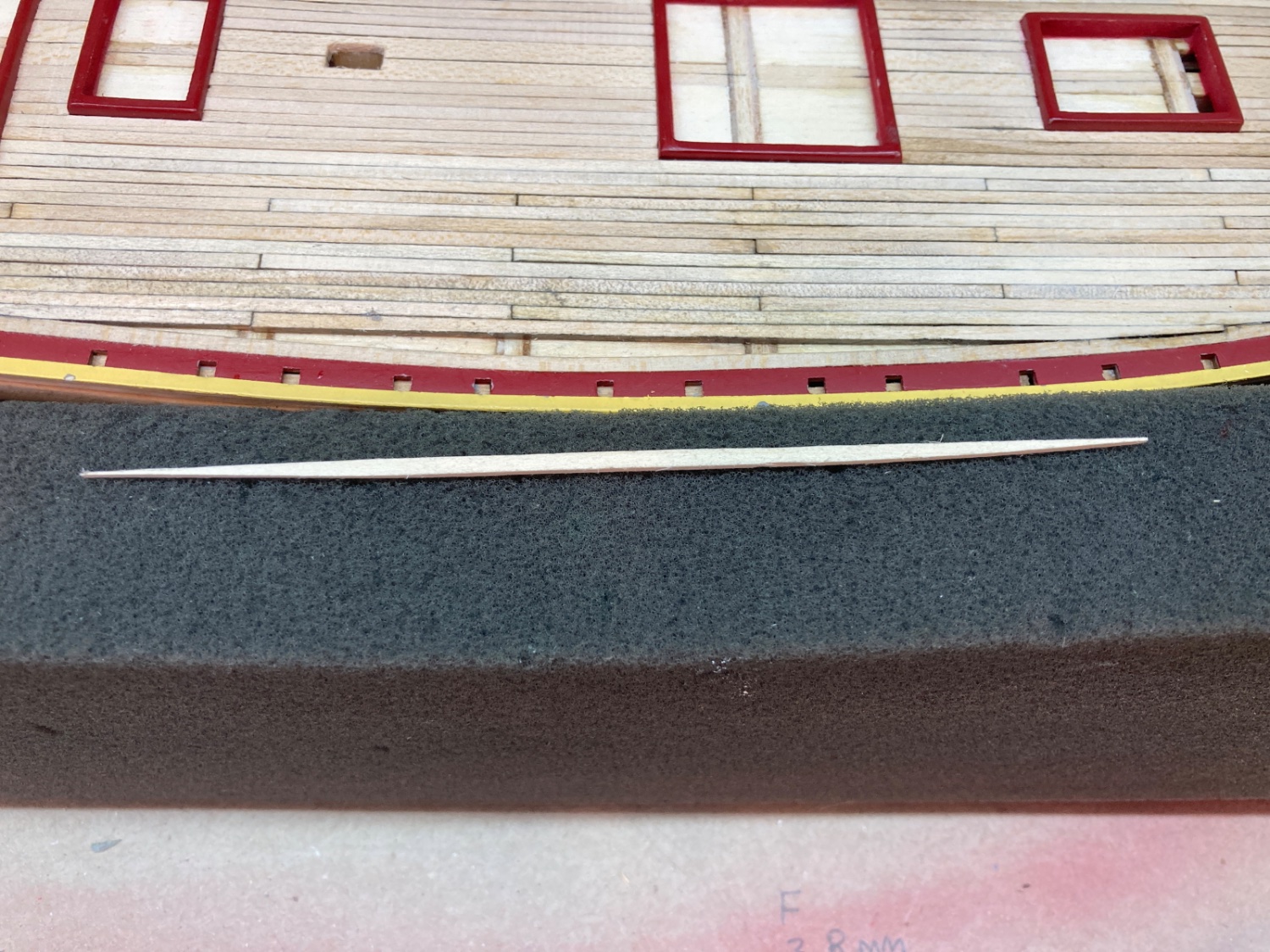
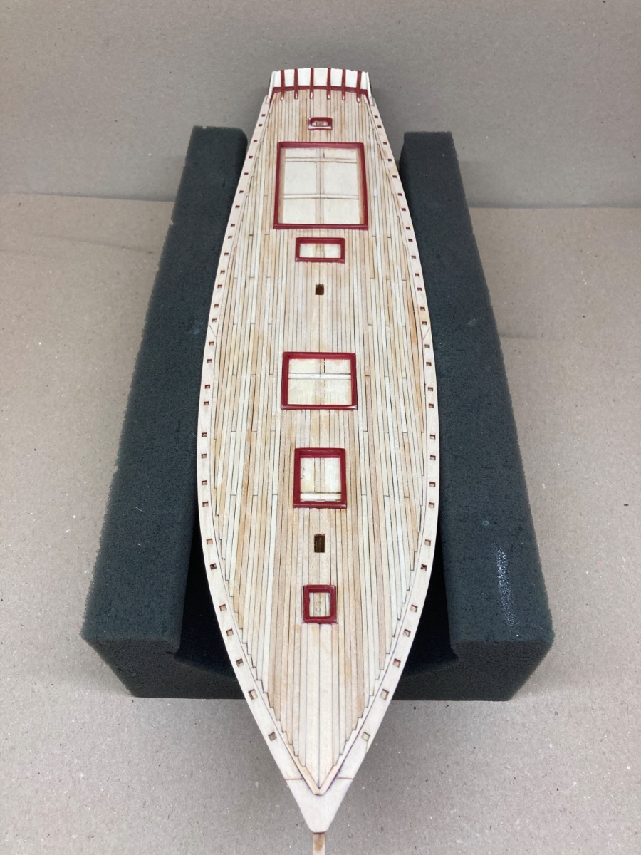
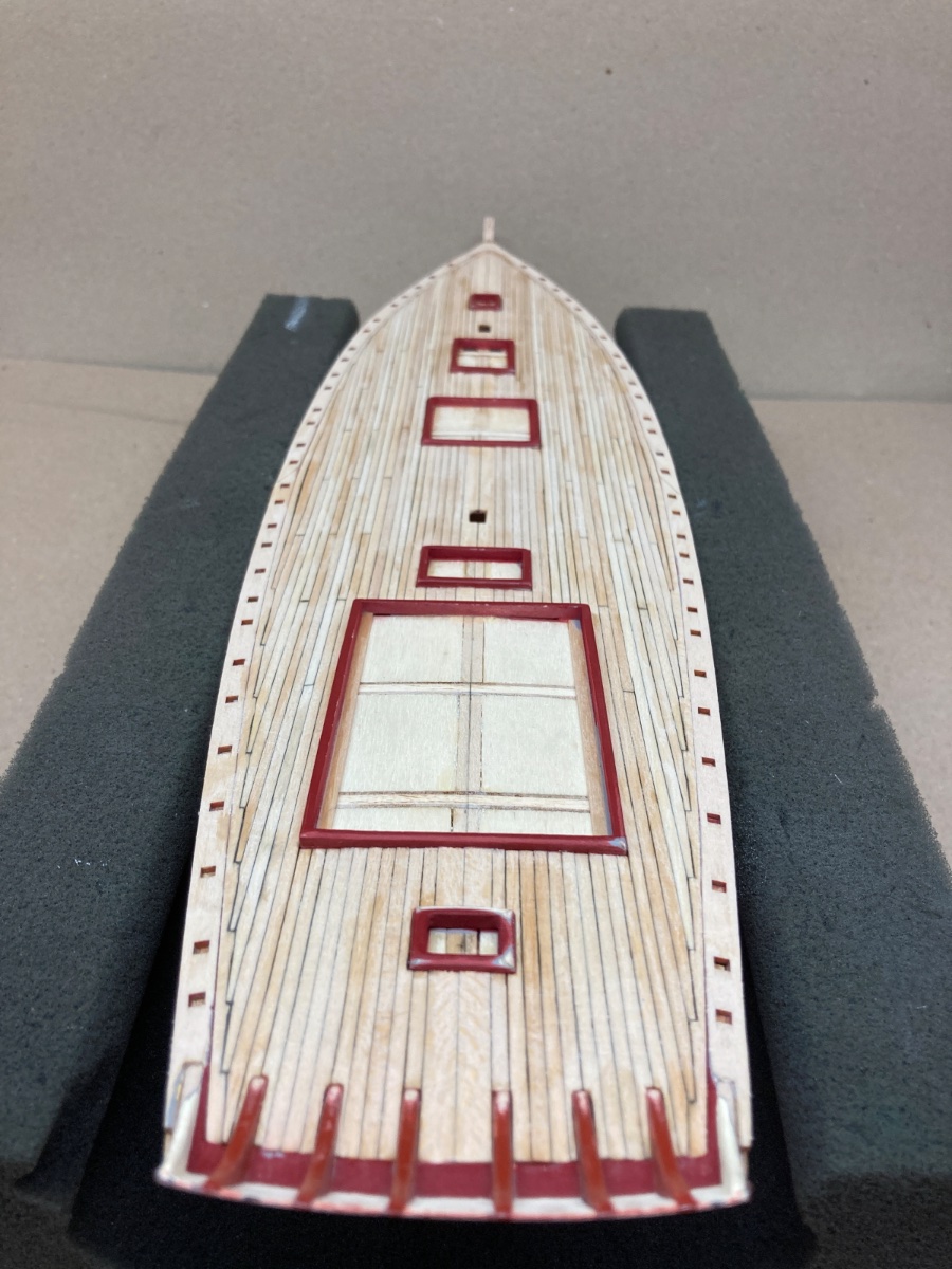
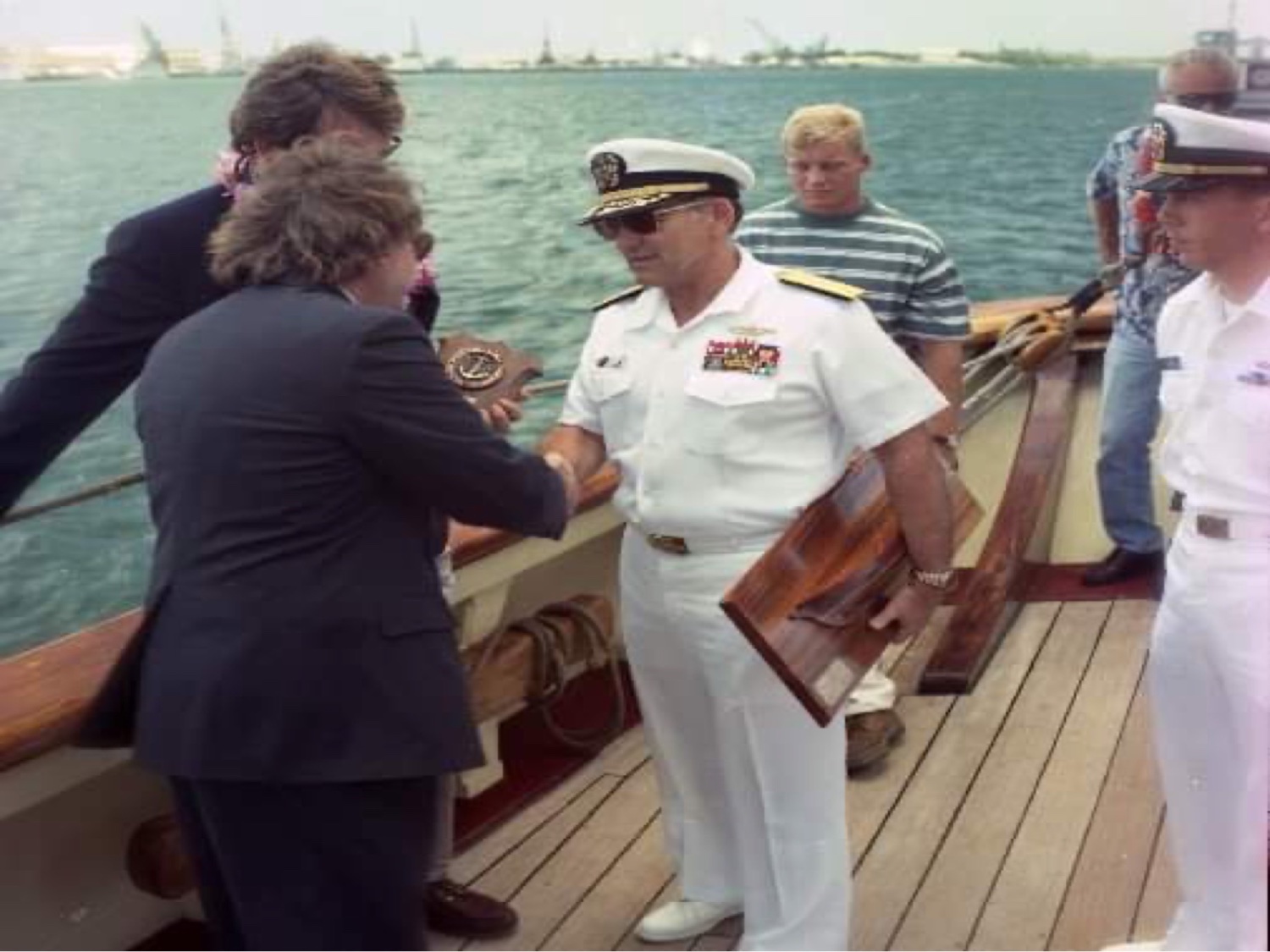
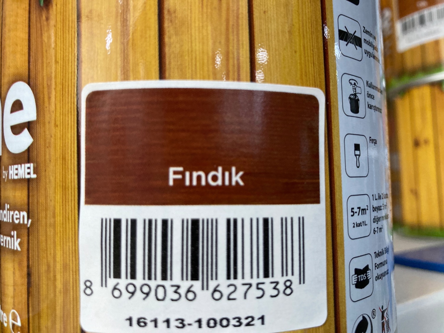
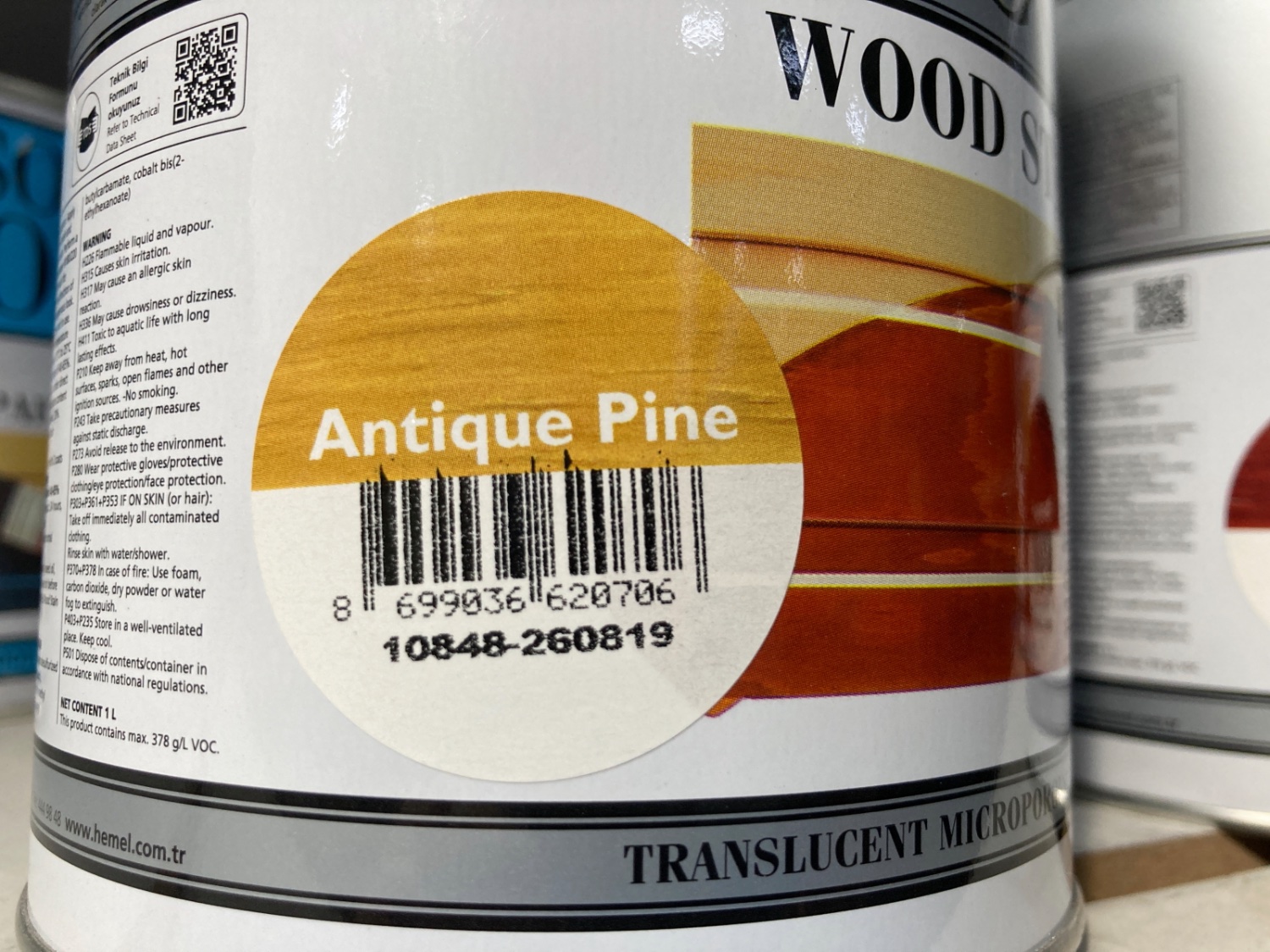
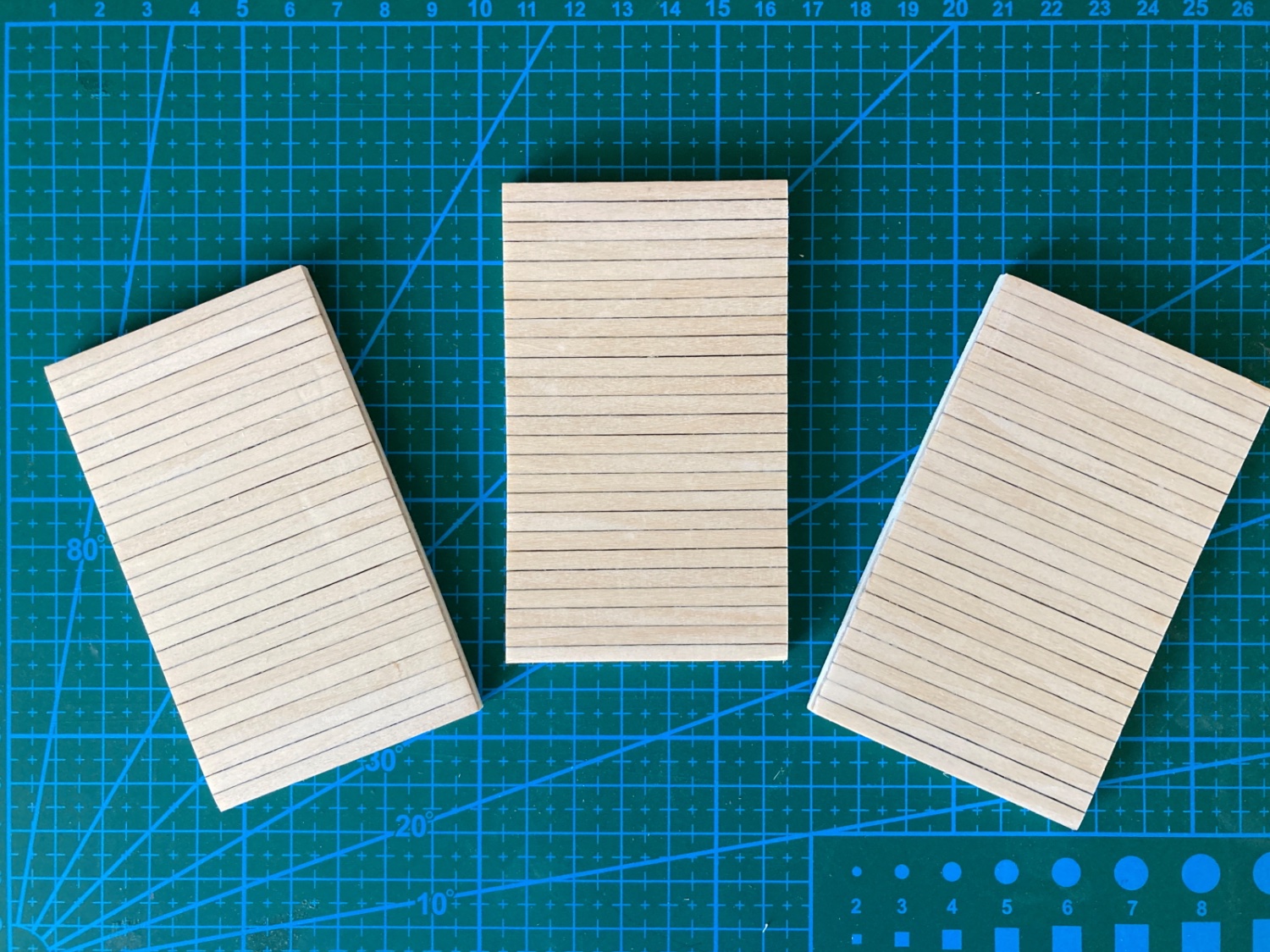
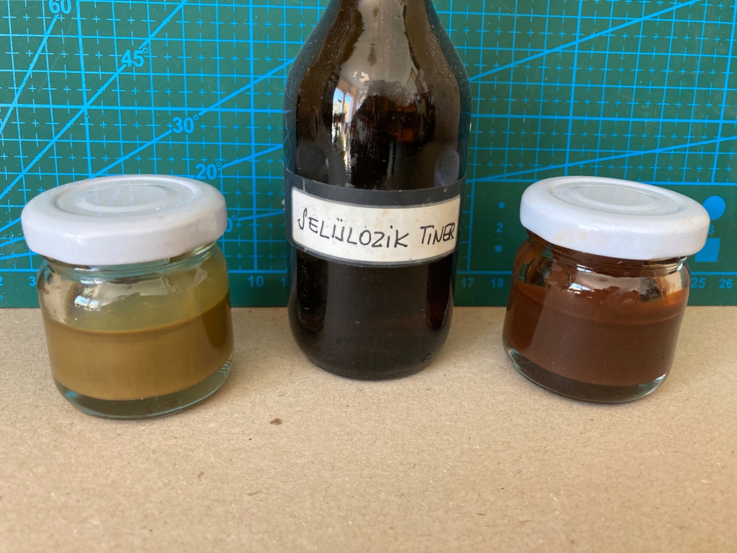
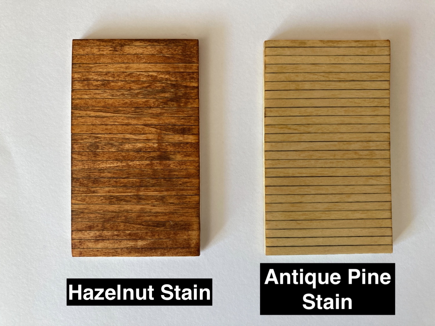
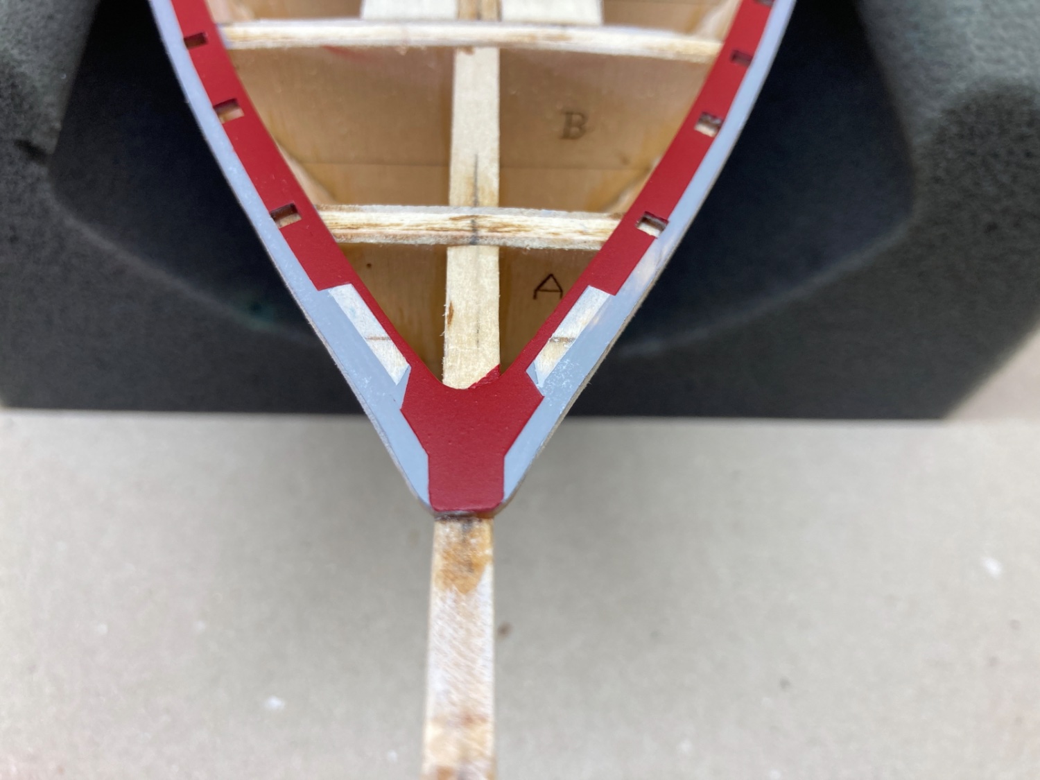
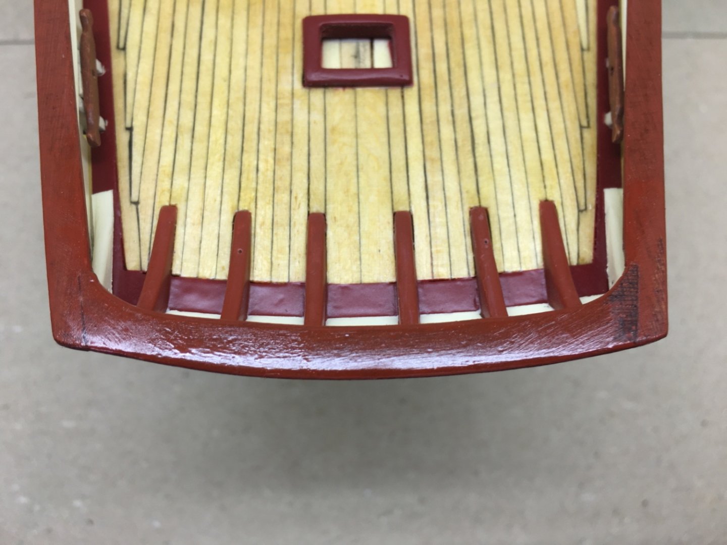
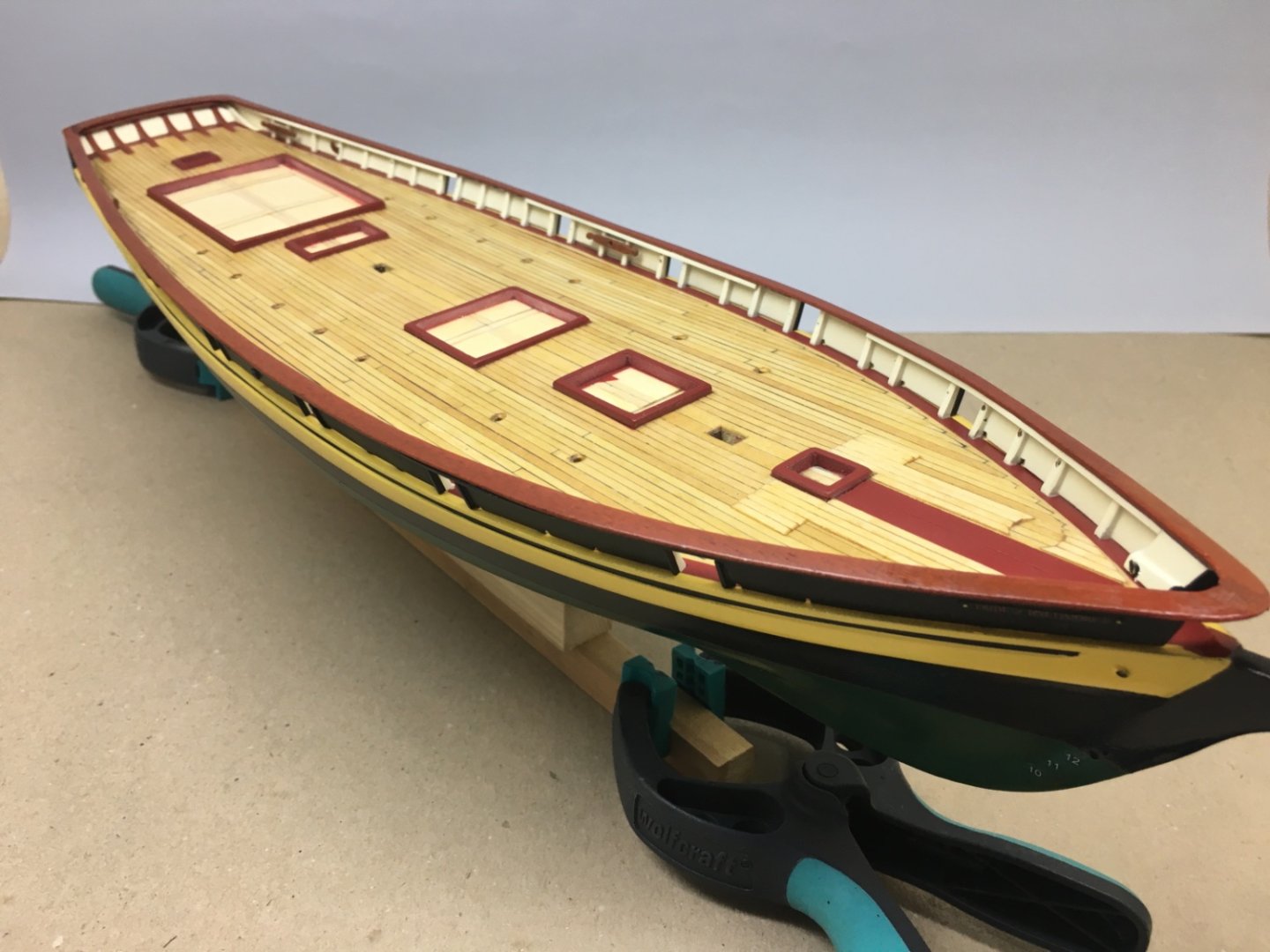
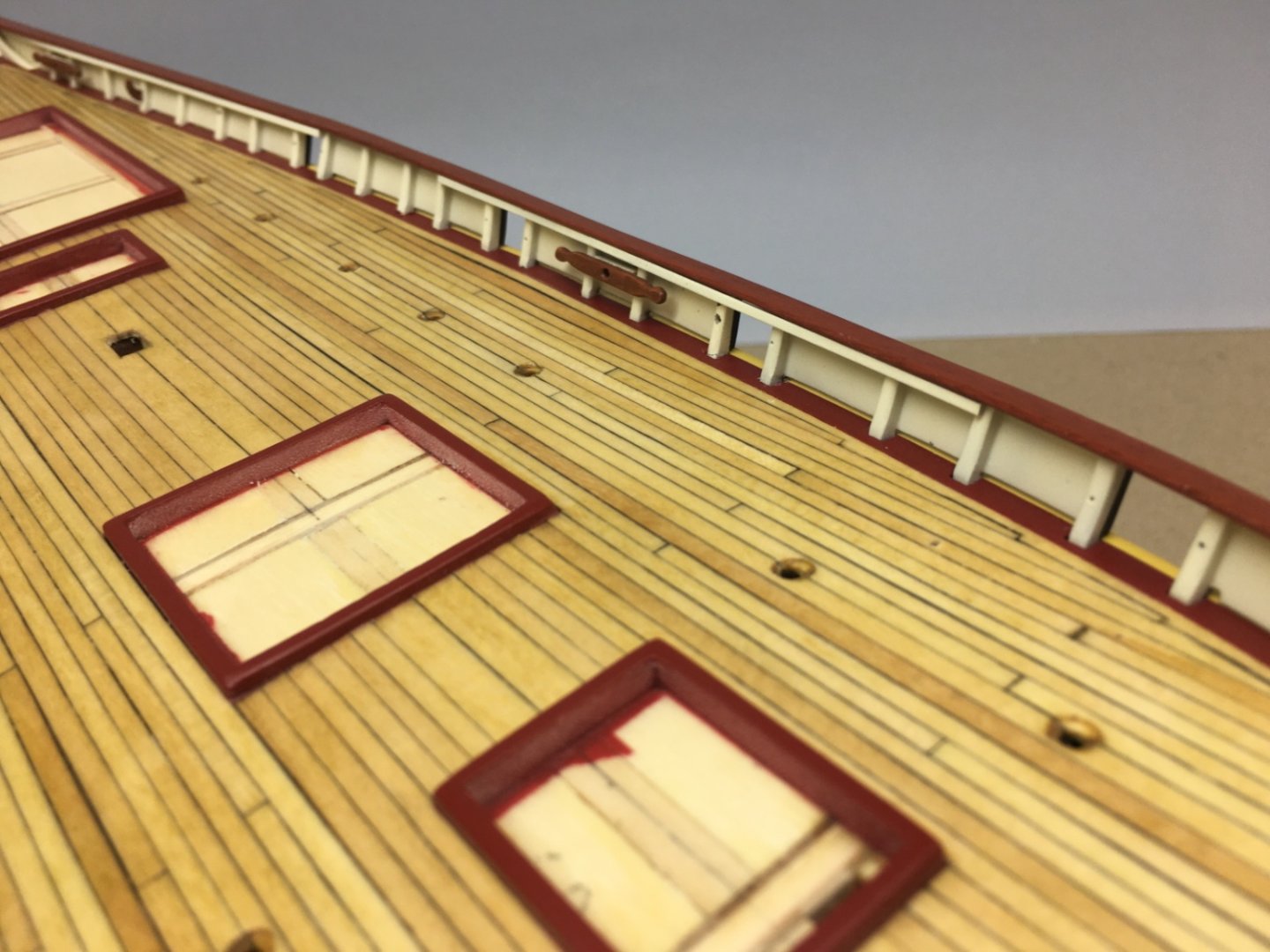
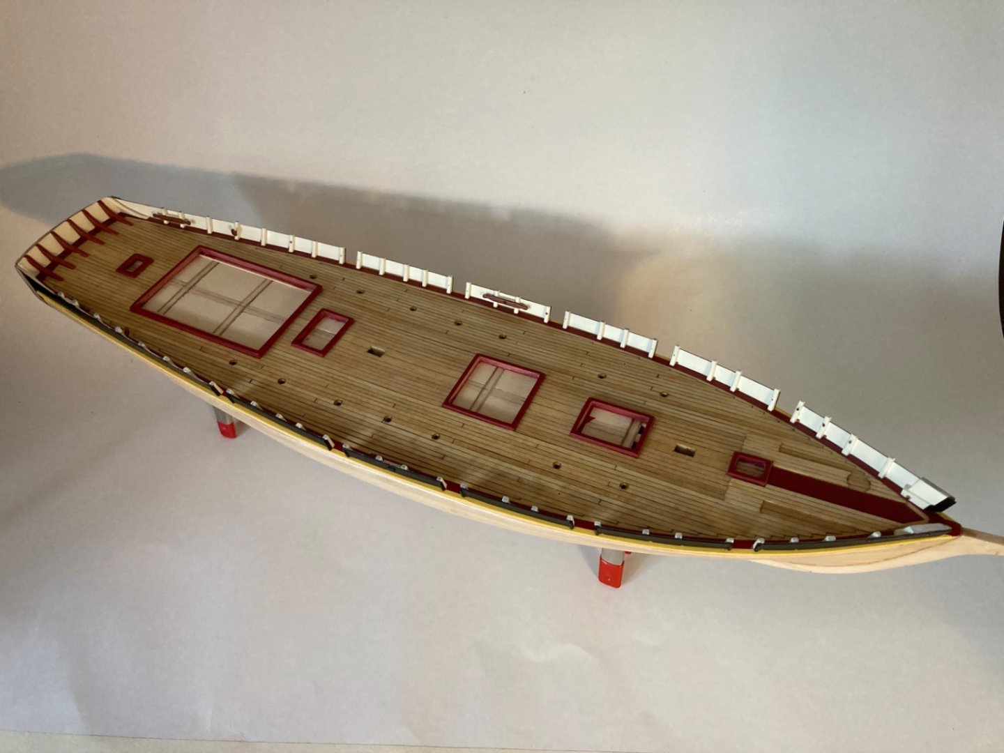
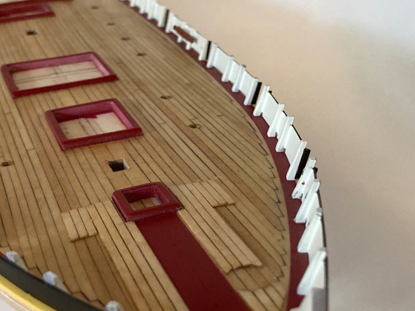
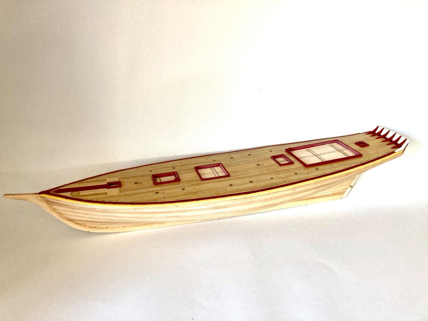
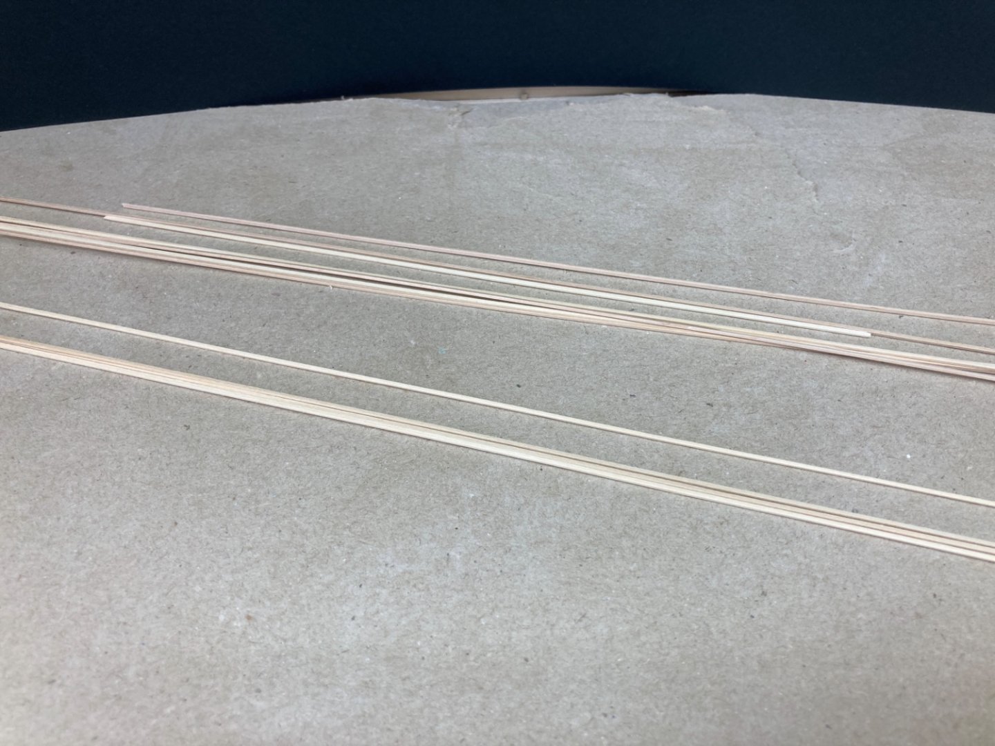
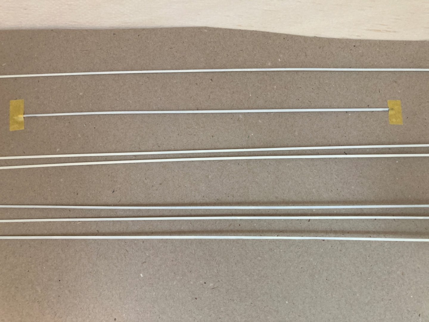
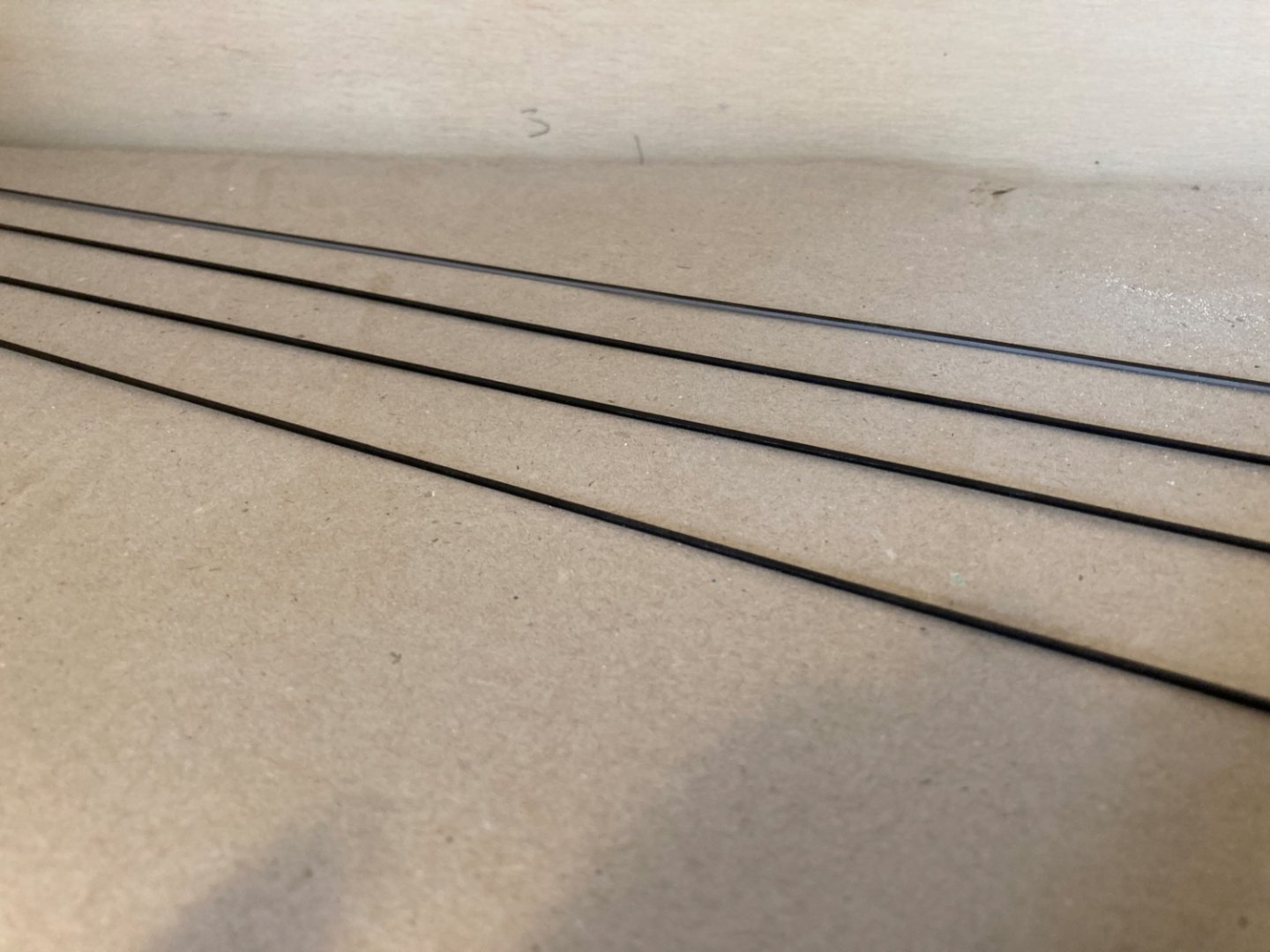
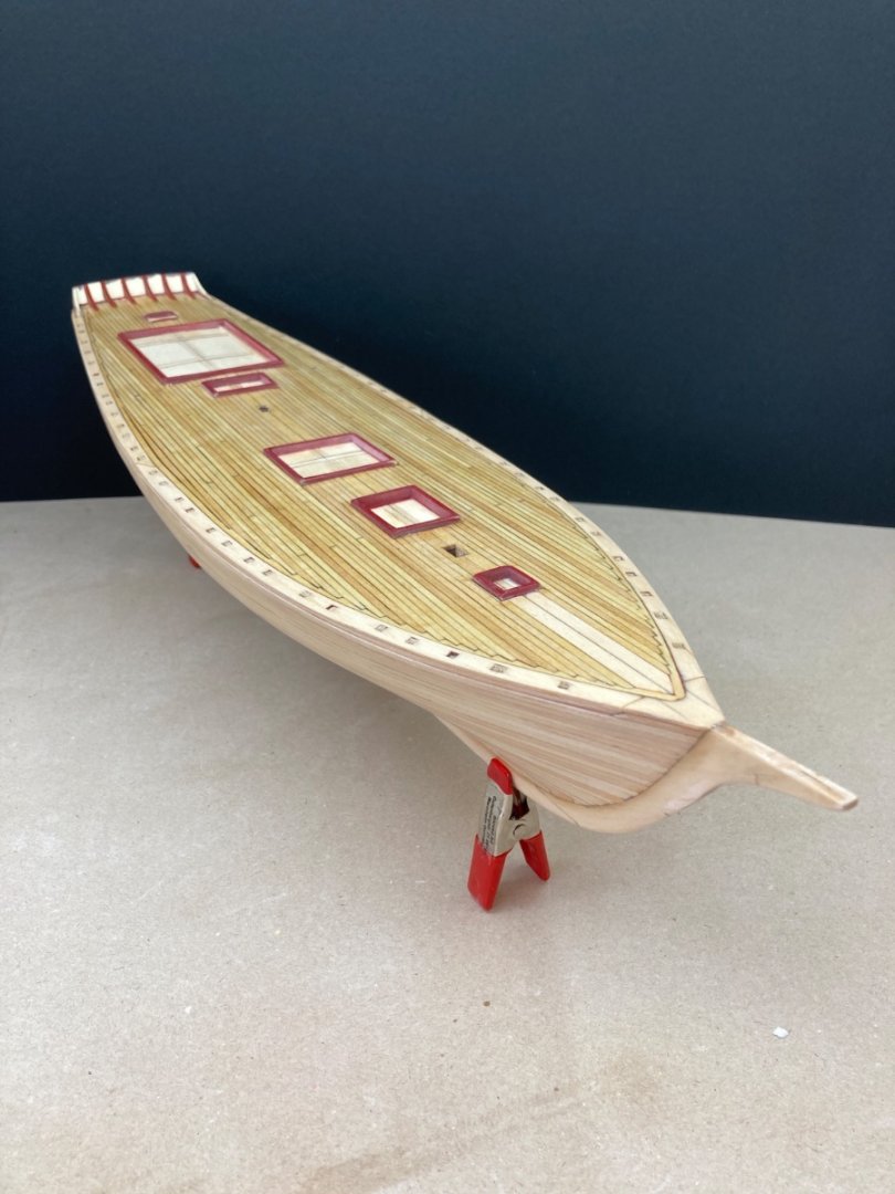
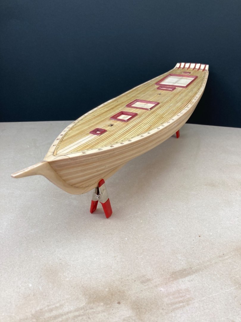
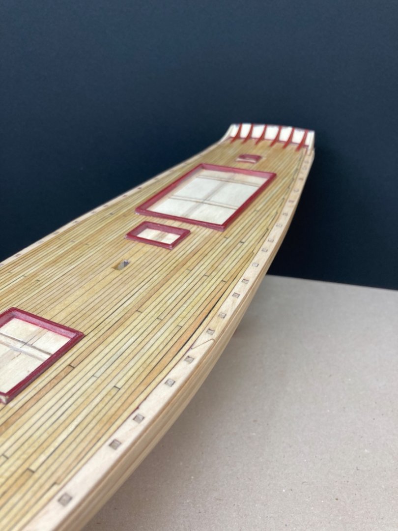
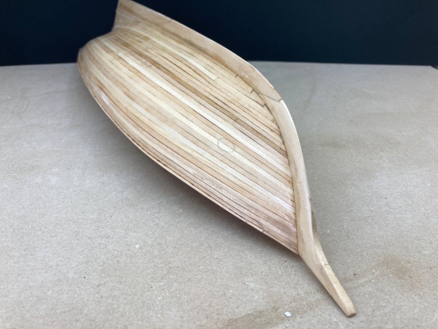
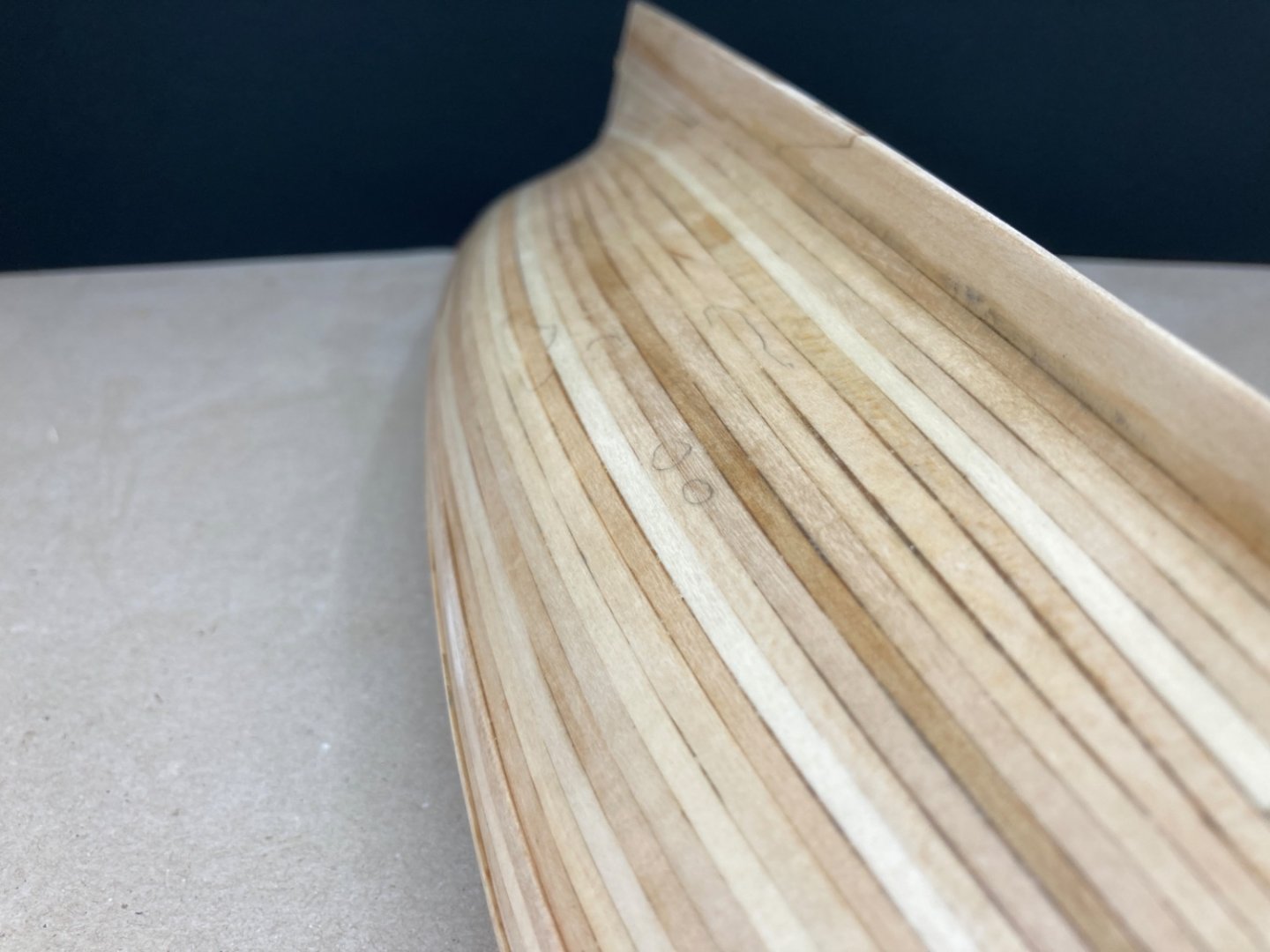
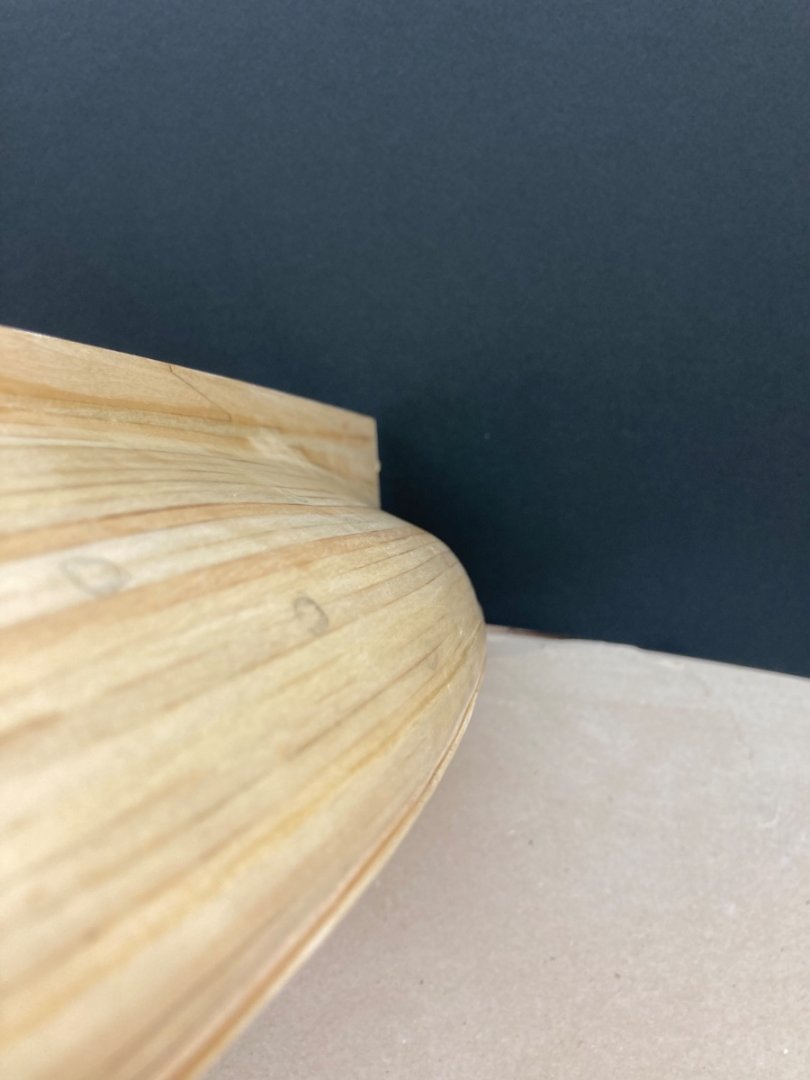
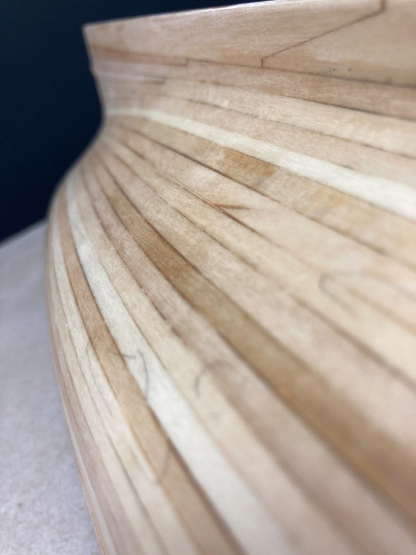
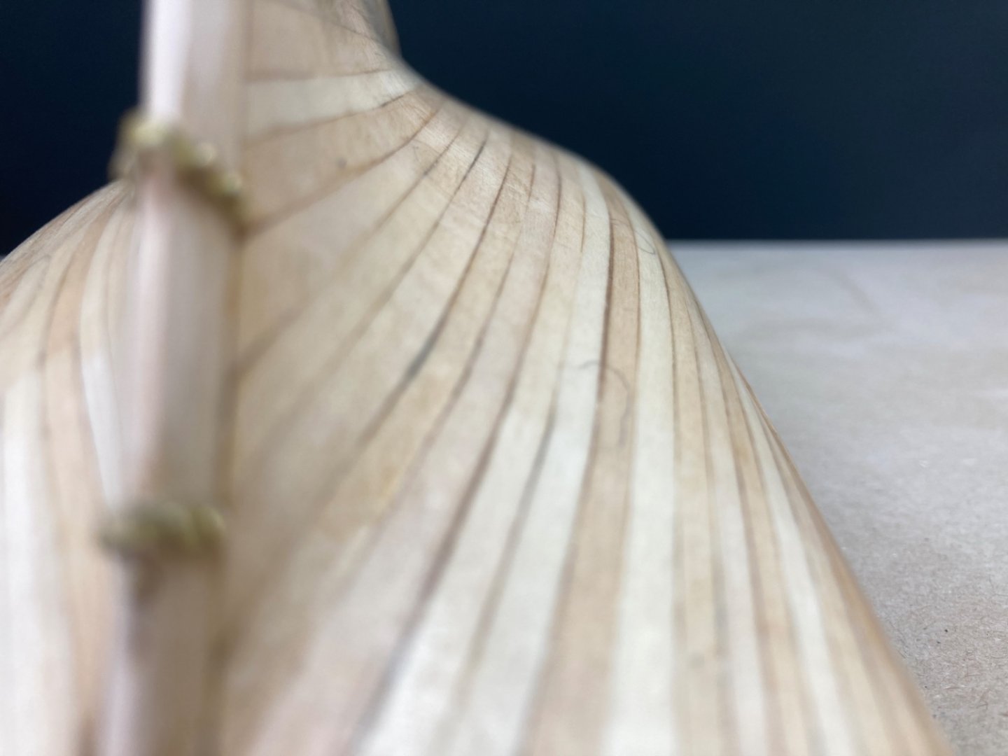
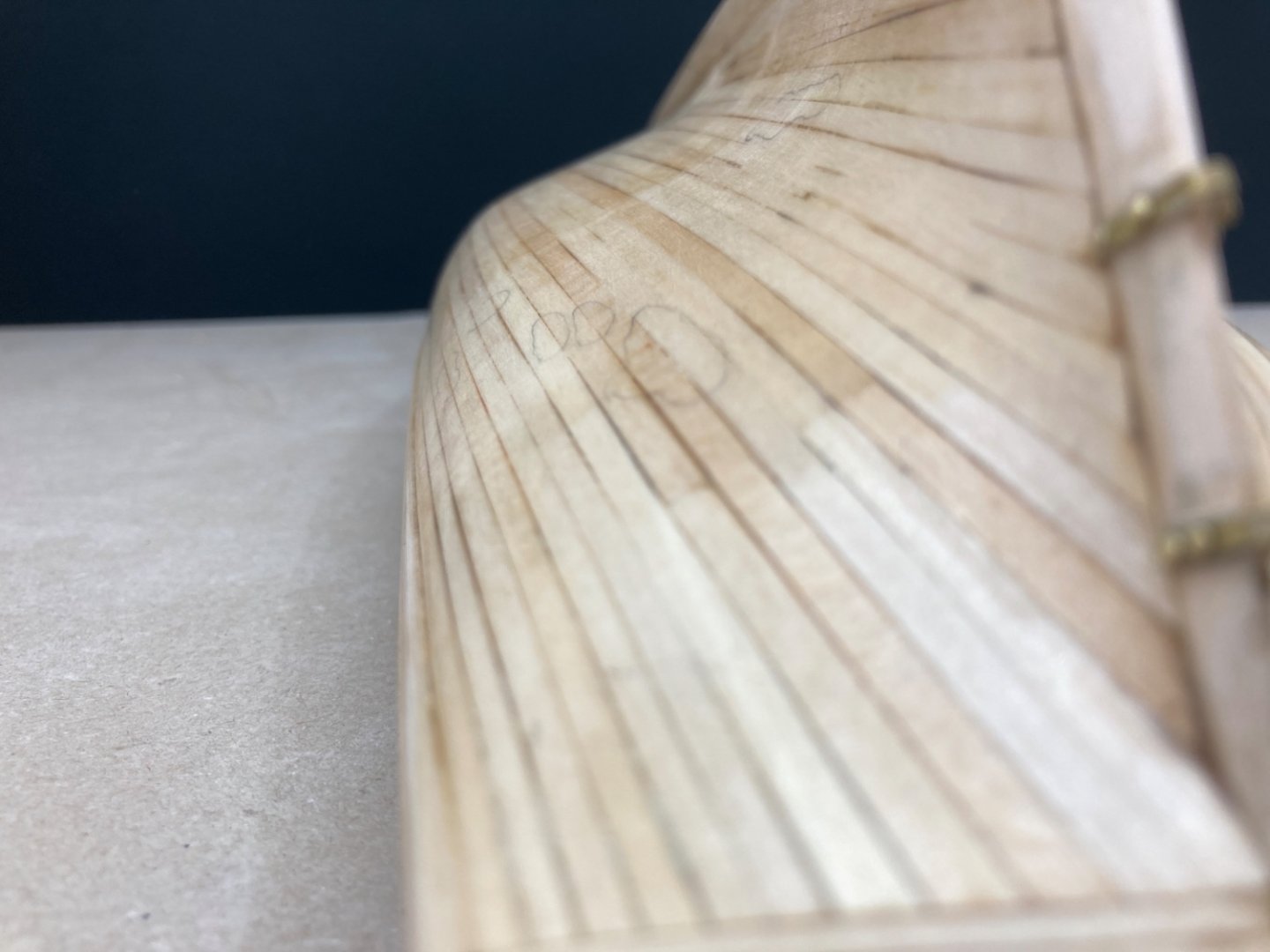
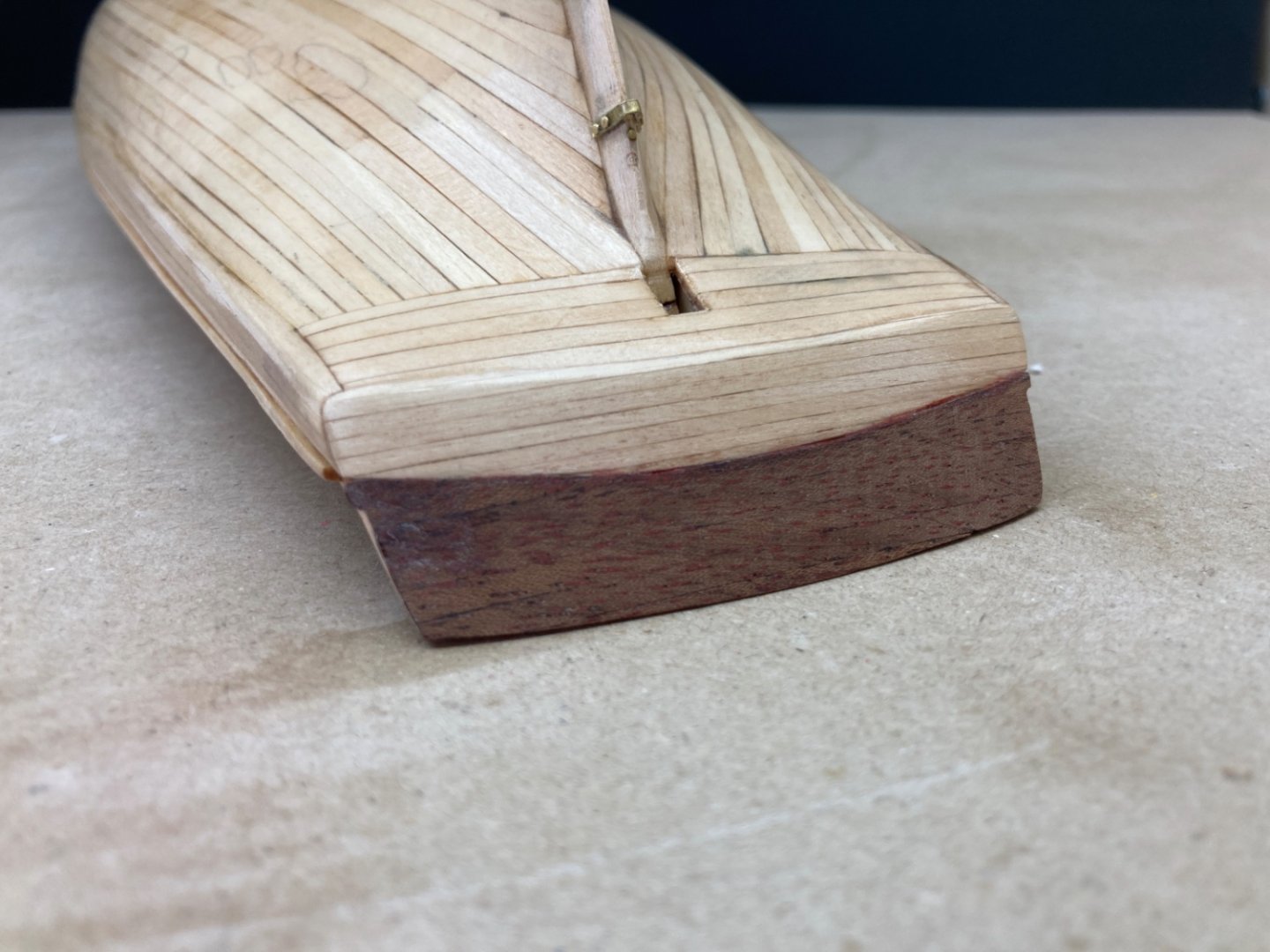
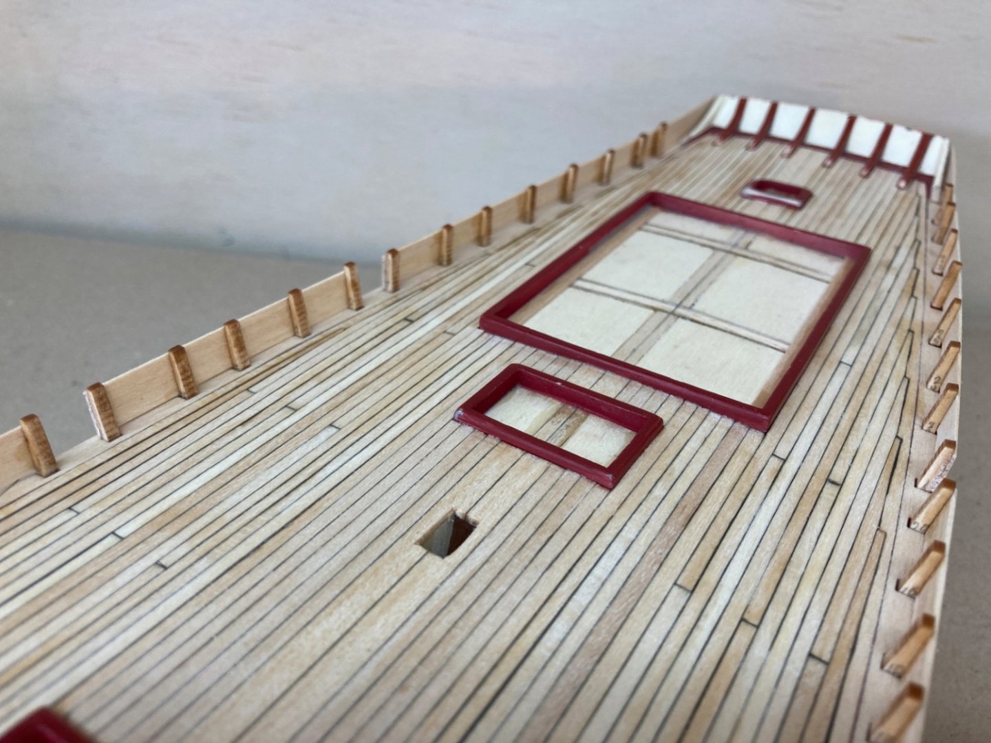
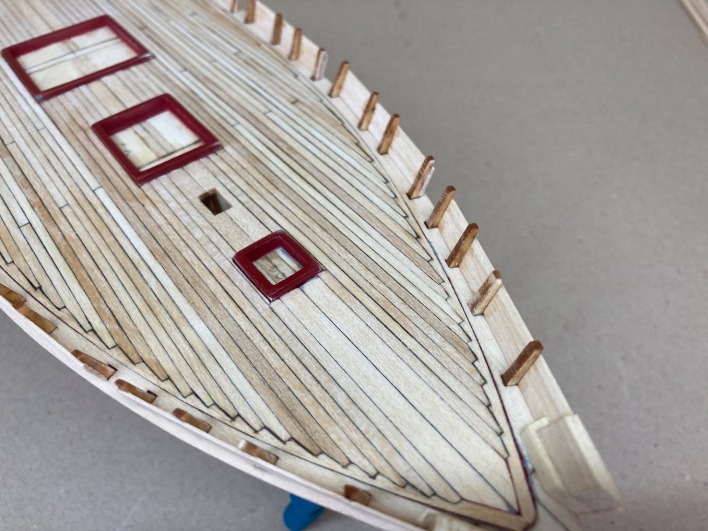
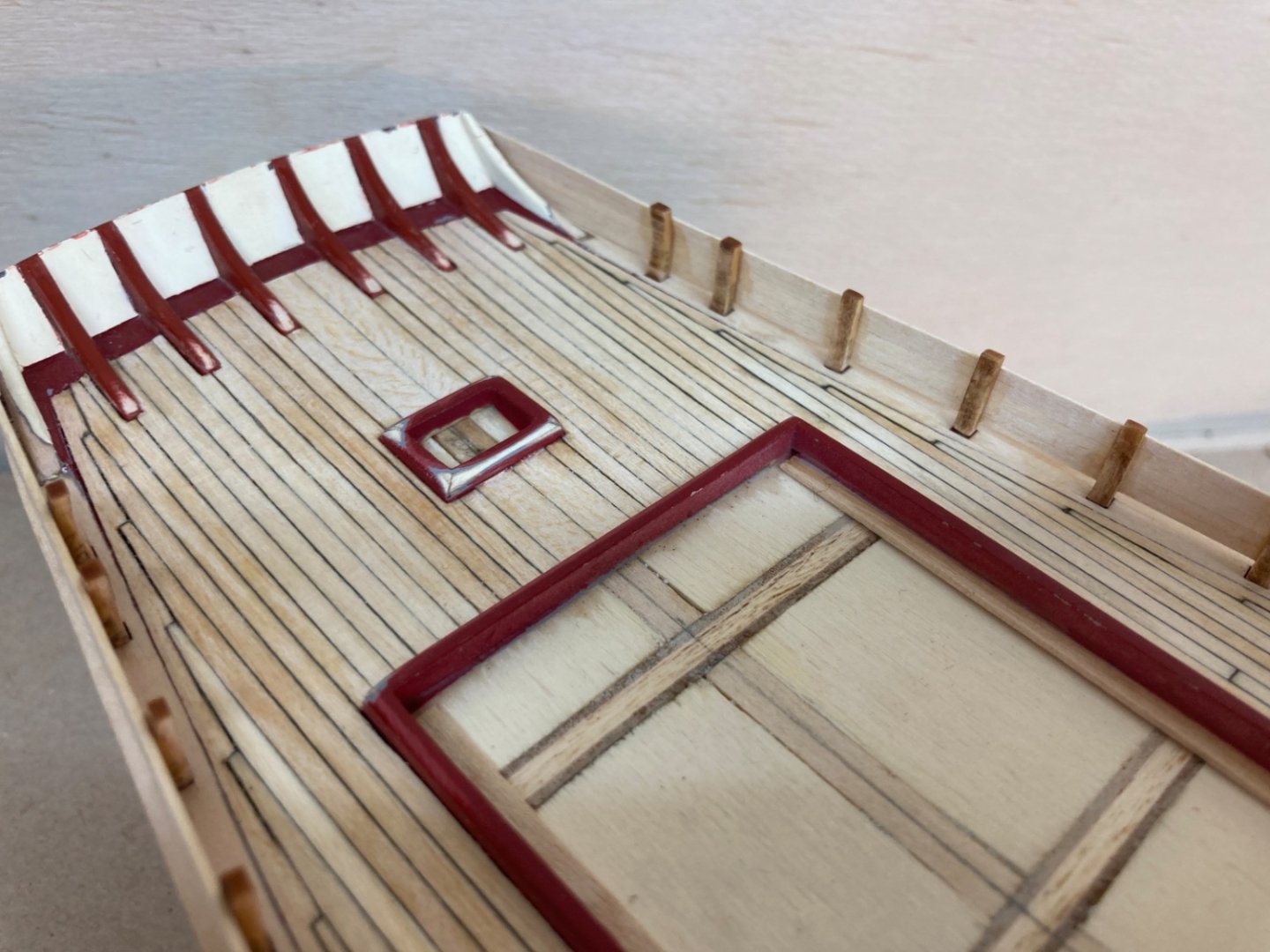
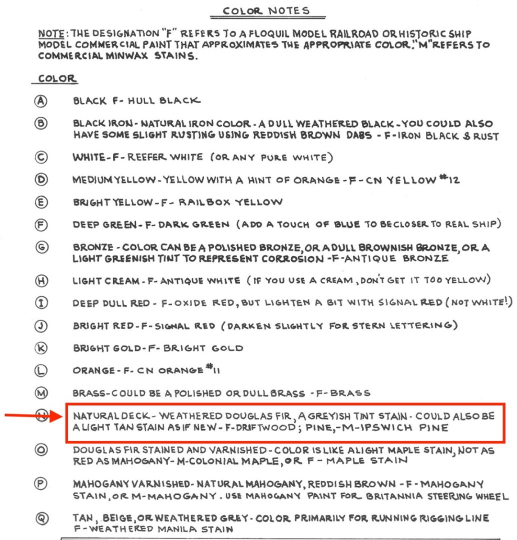
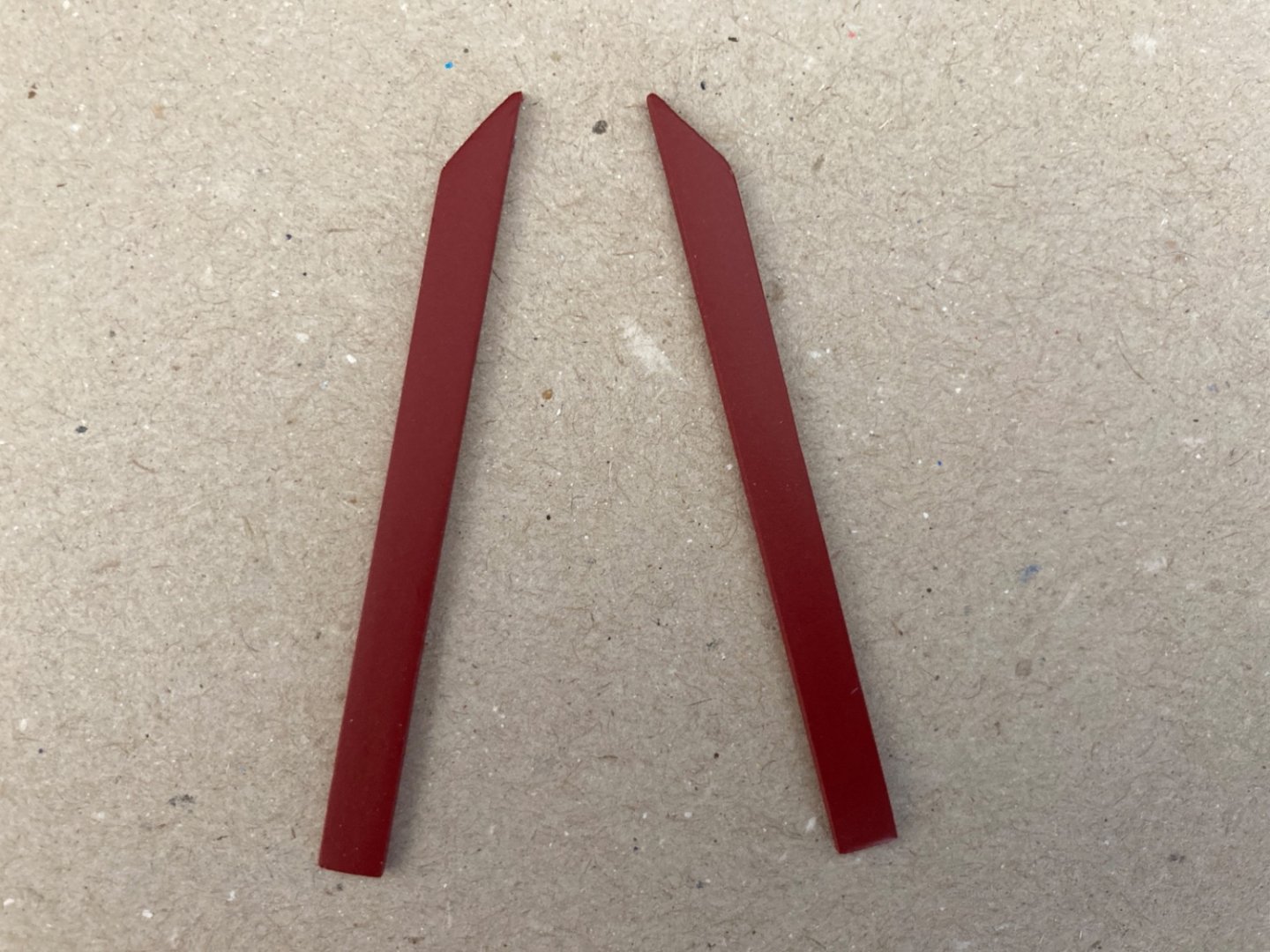
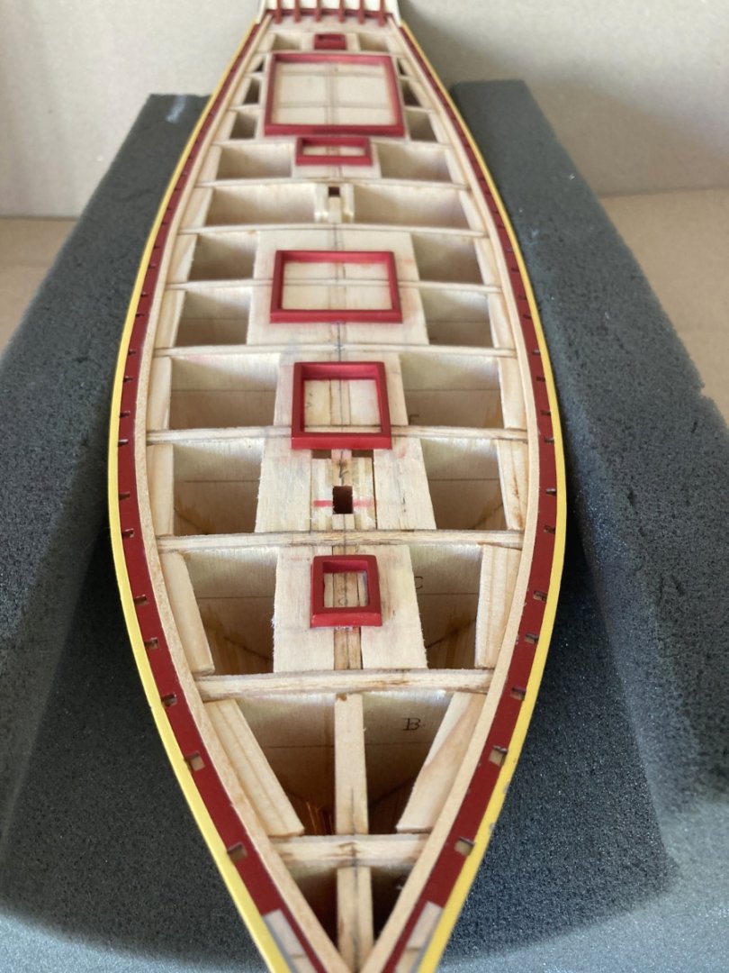
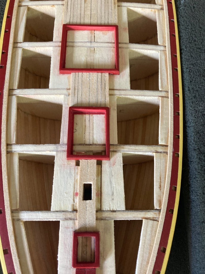
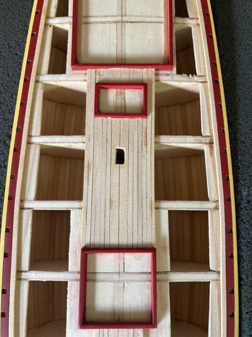
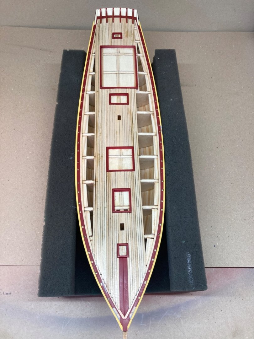
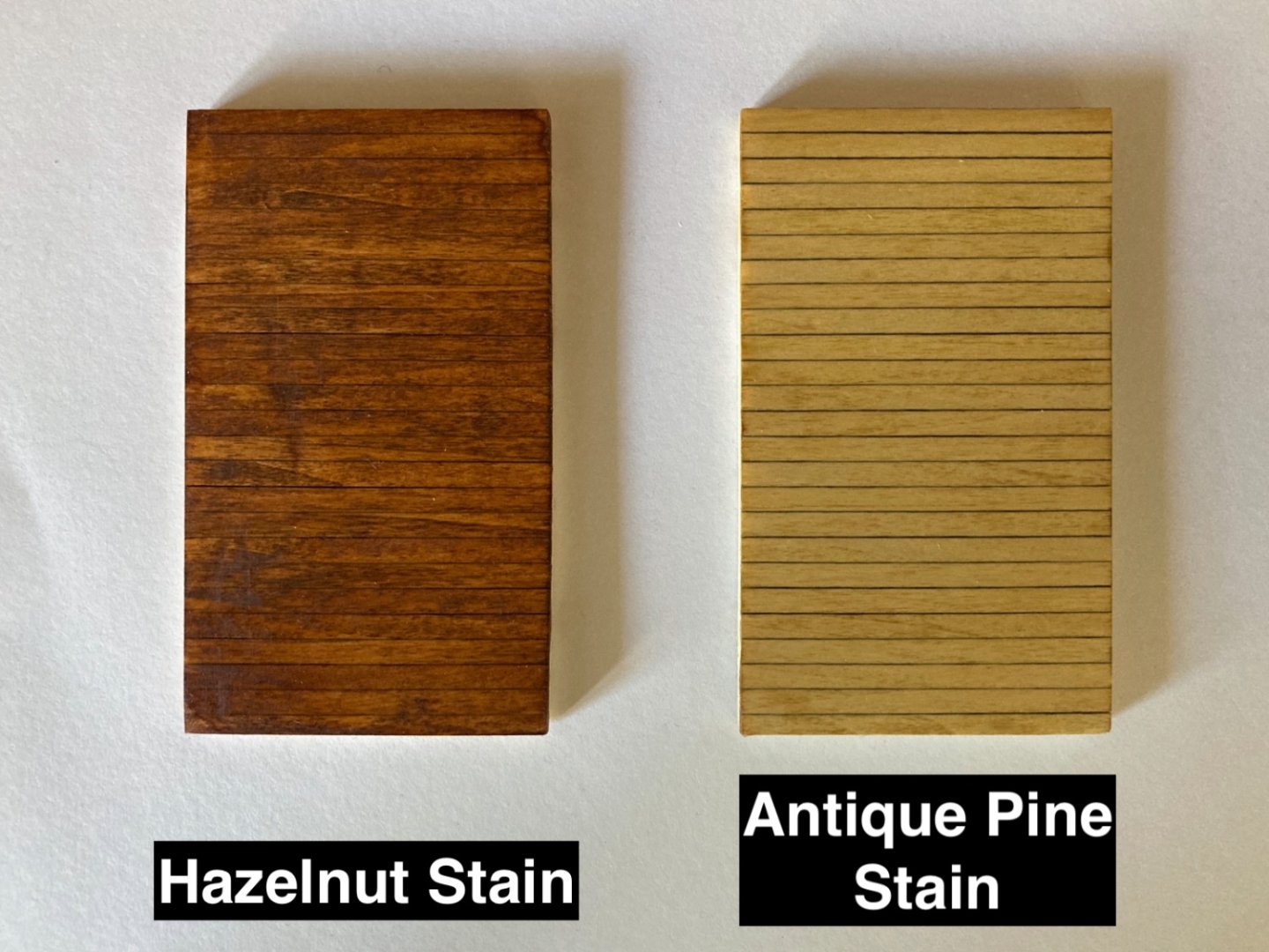
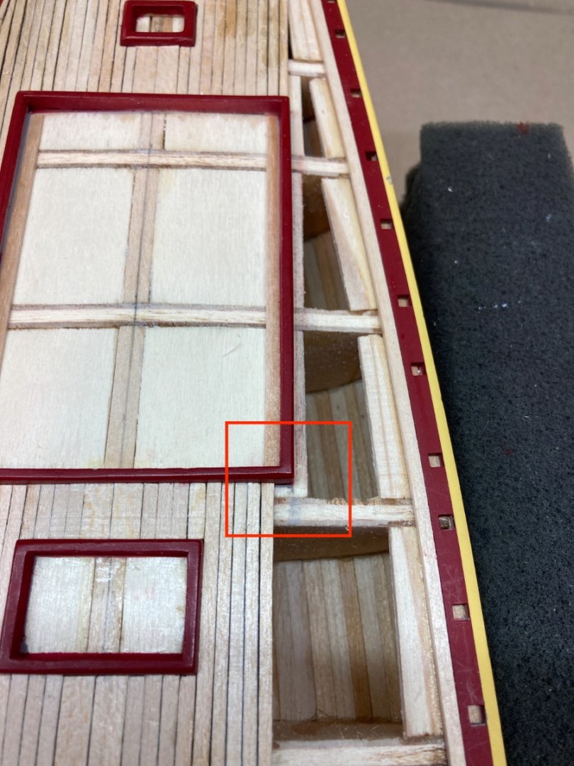
It is now the 6th month of real build time and I was ready to start the deck planking. Deck planking was controversial and caused debates in the build logs I have read. There was a debate about the need for a false deck under the deck planks. And another one about the final color of the planks. As I have placed supports under the coamings and will place more supports under the plank sheers as you will see later in this post, I quickly eliminated the "need for false deck" issue. The deck coloring is given as natural deck- weathered douglas fir and Floquil colors driftwood or pine and Minwax as ipswich pine as references. As the real ship's deck planks are made by douglas fir wood , the ideal wood to use for deck planking in the model was to find douglas fir strips and use them ,leaving you to do the finishing by clear varnish only. However finding douglas fir strips was hard if not possible and I started with the kit's basswood stock of 1/16x3/32 inch ( 1.6x2.4 mm ) strips. I started with the two strips on both sides bordering with plank sheers. They are called nibbing planks or nib strakes. Those planks start at the bow and go all the way back to stern plank sheers. After installing the nibbing planks I added wood pieces under them and plank sheers, just like the ones under the coamings for support the planking . Then I began the deck planking starting from midline. The two planks on both sides of midline are larger than the rest. They are 1/16x3/16 inches (1.6x4.8 mm). The most fore piece of them between the first hatch coaming and bow is red in color.Those were prepared and painted before placing them into final position. The rest of the midline planks are cut and dry fitted first. Here care is needed for aligning the spaces left for mast insertions. After checking their alignment with the midline , from bow to stern , they were glued in place. One thing to mention here is not to forget to color at least one edge of each plank with a 5 or 4 B pencil. This is for the caulking effect. This was done before gluing those two midline planks. My deck planking plan was to do the planks between the coamings and stern sheer planks and bow first. Those planks needed no interruption and are pretty much straight forward. Then comes the fun part. For the planks which meet with the nibbing planks, nibs are cut. The first ones were of course not ideal but as I progressed they became much more better and satisfactory. At this stage I also started to create interruptions and connection lines when cutting and placing the planks. So far I used the planks with their original size and changing was not necessary. Planks at the starboard fore corner of the largest coaming (after cabin) made a smooth and nice border ( Red rectangle) as seen in the photo below. However this was not the case for the same area on port side. The space remaining for planking on the fore edge of the coaming was large for a plank to cover . I was left with a choice of placing one wider plank or continue with 3/32 inch (2.4 mm) original planks. In the latter case 2 planks were needed and one of them will overlap the coaming edge causing the plank coming from stern to be somewhat irregular in size. Had I chosen to place one wide plank ( which must be 3 mm) the visual continuity of the planks will be damaged. This was also the case if I used two 1.5 mm planks. Here is a dry fitting photo if I had used a 3mm plank. Here is how I solved the problem. I stripped off the already placed one row of planks all the way to bow. Then prepared two 2.7 mm planks (red arrows ) and placed them and maintain the visual regularity. The problem at the port side was solved. The rest was easy and straight forward. With the preparation and placement of the most lateral planks , planking of the deck was finished. Starboard side Port side Whole deck. Please note the paint demage already started in planksheer even before sanding. Also note the color changes on the deck which are due to repeated applications of gap filling CA glue in order to seal the caulking as well as fixing the planks and probably to some residual finger skin also !!!. As there some narrow and tight areas to be sanded , between coamings and stern knees , suitable wood sanding blocks are prepared. Sanding was done initially by 220 grit paper blocks and followed by 400 grit ones. The paint on port and starboard plank sheers was completely wiped out , leaving only the red image between them and the nibbing planks, which was my main purpose at the beginning. The paint on coamings and stern knees was also damaged and was dealt later. Here at this stage the deck was checked again throughly and all the visible spaces between the planks are filled with gap filling CA glue and sanded again with 220 and 400 grit paper wood blocks finally finishing the deck planking sanding. It was now the time for coloring the deck. As I stated in the beginning of the post this subject was contraversial and caused debate between previous modelers of this ship. After correspondence with the ship crew they mailed me the below photo and said this was the oldest photo which they had, showing the deck color. Throughout the years of maintenance , service and modifications the color changed and became somewhat darker as seen in the following photo. However I came across to the most recent photo below showing the color almost identical to the oldest one. The ship is under heavy maintenance nowadays , clearly noticed by the removed masts, rigging and rail life lines to name a few. Probably heavy sanding was done on the deck planks reveling the original color of the deck wood. I visited hardware stores and checked almost all the wood stain colors and finally purchased two and made experiments on pieces of wood. The colors were hazelnut and antique pine. Hazelnut Antique pine I prepared planked wood for sampling . Diluted the stains with lacquer thinner. Applied two coats. After first coat After second coat Finally I choosed the light color , probably thinking to achieve a nice contrast with the bulwark rails, mahogany hatch tops and cabin trunks, maple colored masts, dark colored windlass and etc. How to apply the stain ? I was a bit hesitant to use airbrushes , fearing that the cleaning them after use will be a hard job, as I have never used them with stains. So I decided to use two suitable and same sized cut brushes. One for applying the stain and the second one for wiping out the stain residue immediately after the first brush action. Before the stain application to deck I have stop here and this time will follow the chronological timeline of the build, because there was an important step before the stain job. The preparation of bulwarks was done before the deck staining and I have to post how I handled them first.


- 114 replies
-
- 6
-
-
- Pride of Baltimore II
- Model Shipways
- (and 1 more)
-
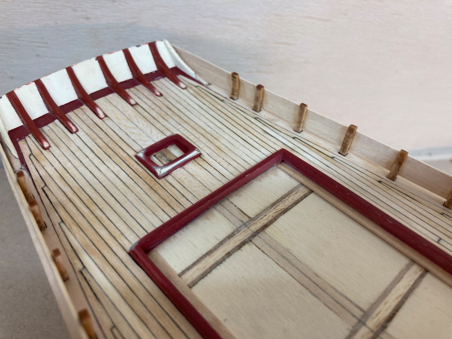
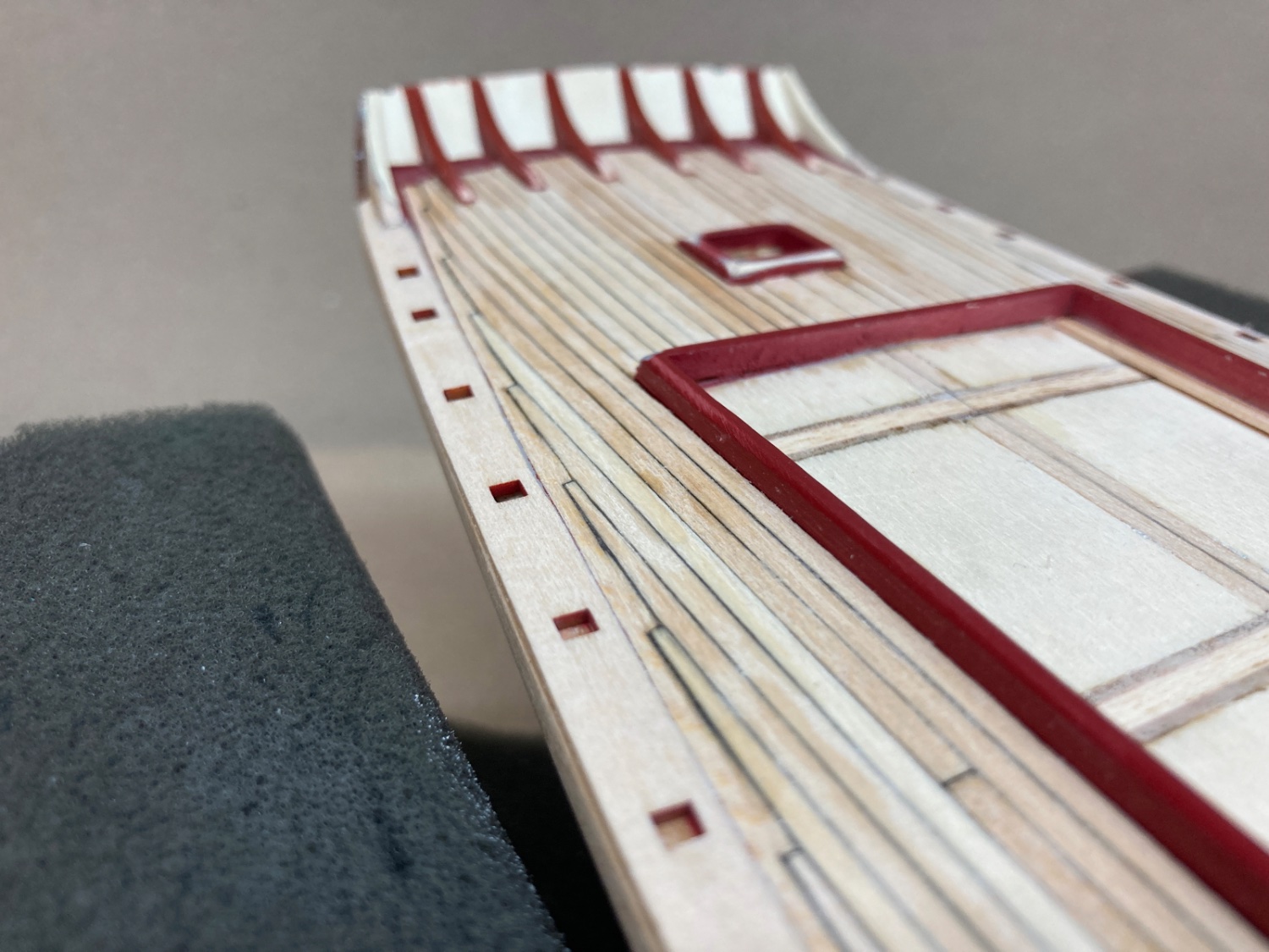
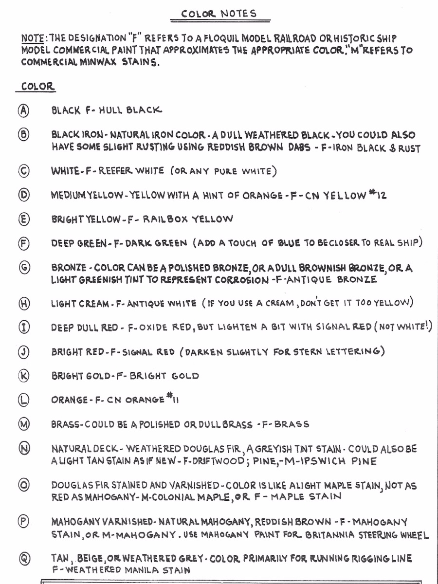
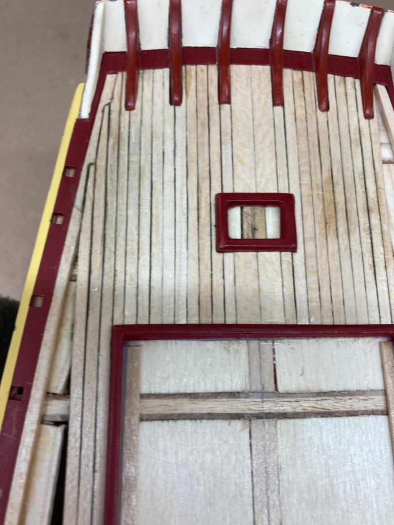
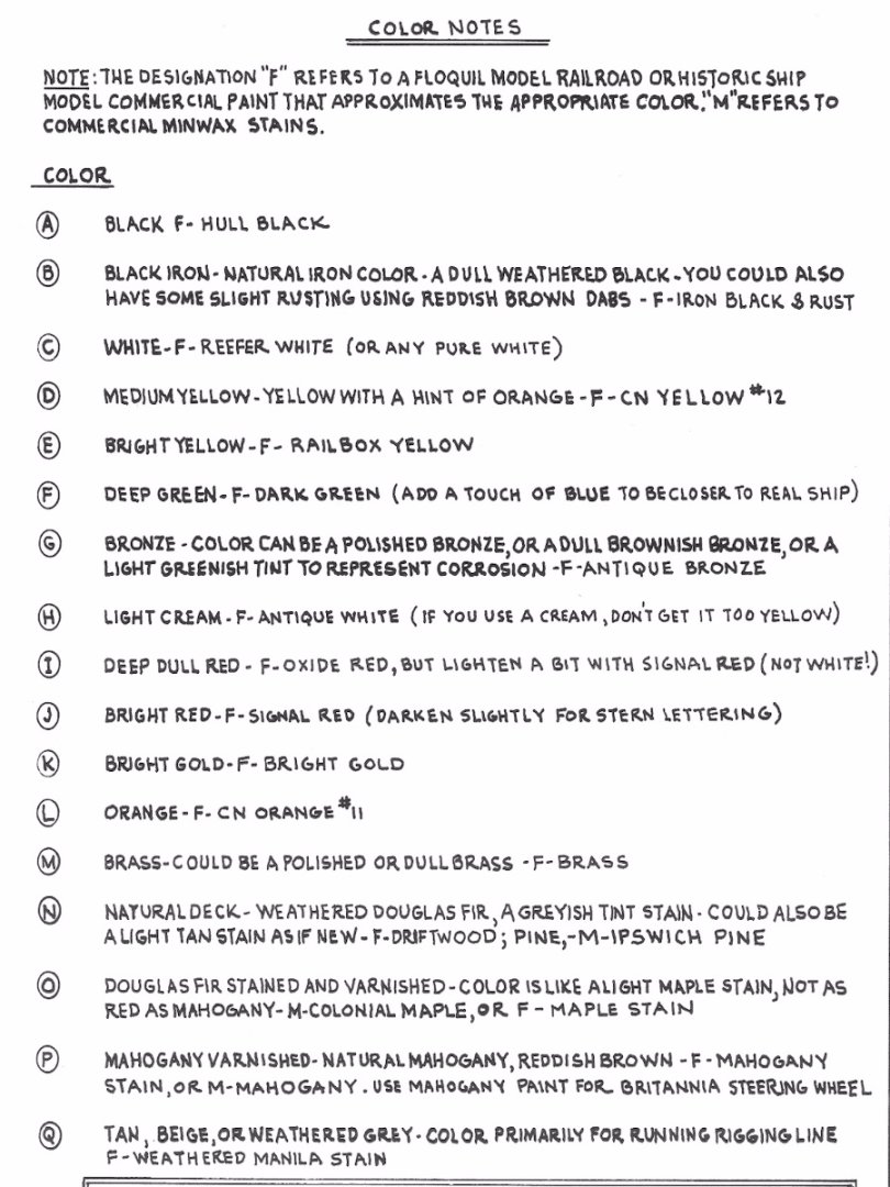
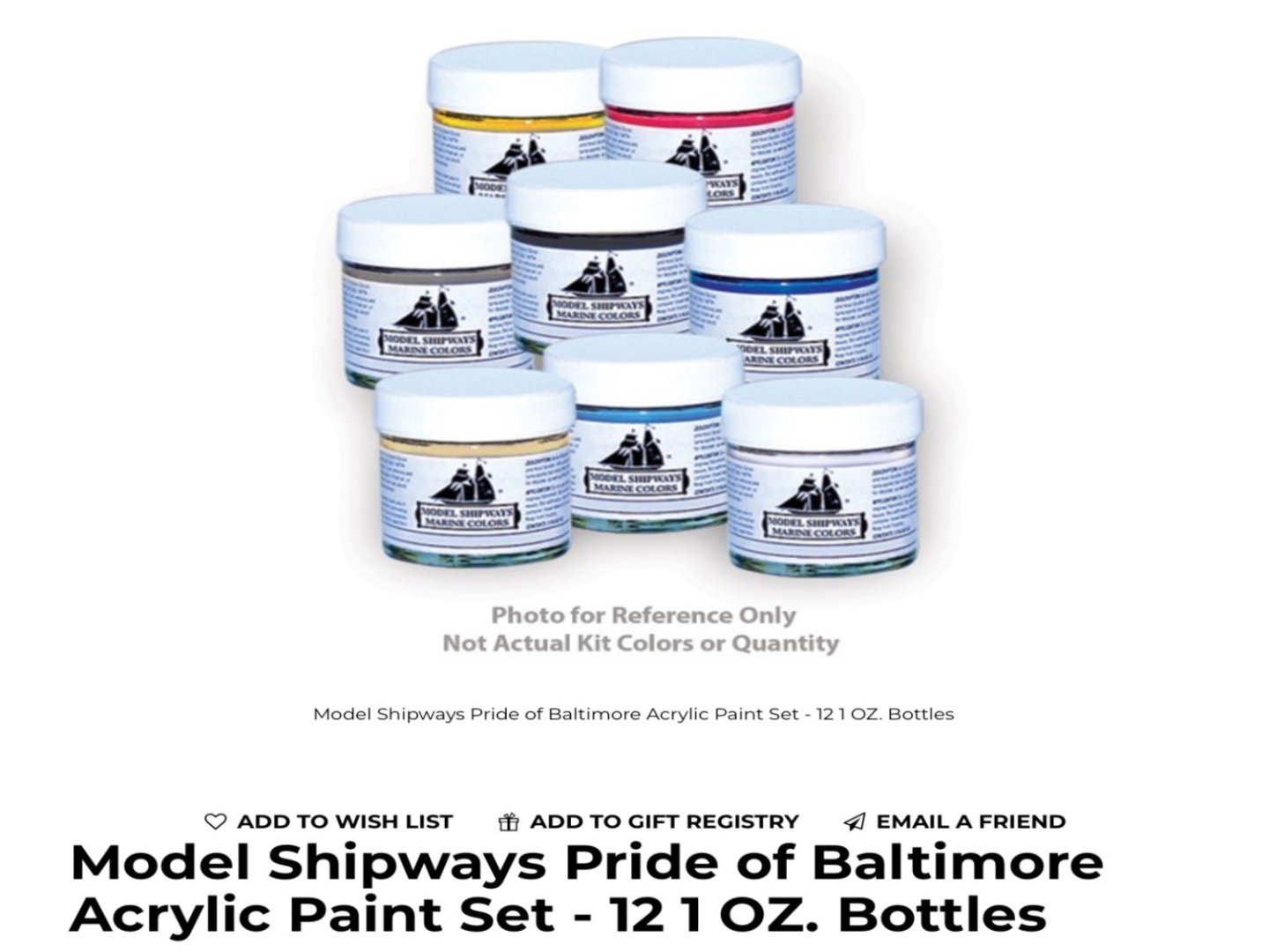
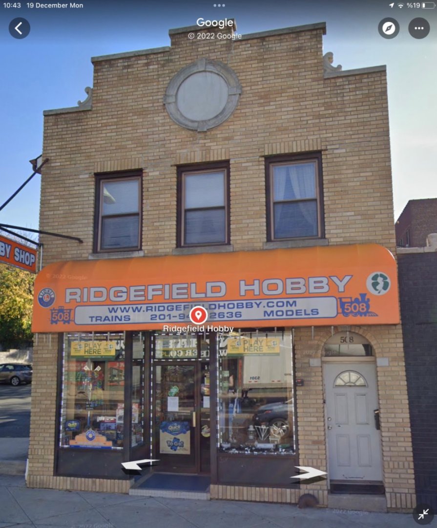
I decided to paint the coamings, plank sheers and stern knees which deck planking will have mutual borders with. My purpose was to have nicely painted edges and a clean border between the coamings, plank sheers and stern knees with the adjacent deck planks . Model's paint list is nice and descriptive. However the color references were given with Floquil brand. A quick search on internet resulted sadly with bad news. Floquil was not produced anymore and almost unavailable on market. I was looking for alternatives solutions at that time and discovered that a 12 bottle paint set for POB II was on sale on Modelexpo web site. So on my next visit to my son in Cliffside Park, NJ in 2014, I did purchase that paint set. During that stay I discovered a small, family run hobby shop (I was always looking for trouble !) in Ridgefield, NJ located at 508 Broad Avenue. One day my son took me there. The shop is run by an old couple and the main theme was model railroad items although there were quite a large collection of plastic models on the shelves as well as paints and other tools. Owners were friendly, especially the lady, and were interested on how I found their shop when I told her where I was from . During the chat I saw a cardboard box with a ' $ a bottle' sign on. I surprisingly found out that the box was full of glass Floquil Paint Bottles. The color choices were narrow but it did not stop me buying 25 bottles, mainly for collection purposes. The lady added another free 5 bottles and I left the shop with some other purchases very happy and proud of myself as if I succeeded a near impossible treasure hunt. I visited the store couple of times more in the following days which resulted in purchasing more Floquil bottles. However those Floquil Bottles never reached to my workshop. Here is the reason why. During my stay , which lasted almost a month, I purchased a lot of hobby supplies like numerous Dremel bits, Iwata airbrushes and Iwata Studio airbrush compressor, a lot tools and etc. I was aware of the TSA rules and how flammable items , like Floquil paints , may cause problems if not trouble. The paints from Modelexpo were water based and non-flammable, so they were OK. I even wrote notes on their boxes addressed to TSA officers stating their non-flammable nature. However I was unsure how to carry the Floquil box. Finally I decided to leave them behind and they were given as a gift to a friend of my wife living there and is a painter. A sad story... Back to POB II painting job again. As the model has a large hull surface to be painted and necessitates more paint than a standart model, I decided to use acrylic auto paint. Auto paint shops can prepare almost any color you want and they have many different catalogs (RAL for example) to choose the color you want.You just choose the color and give the color code to the shop owner. The key words when ordering are ' base color' and 'matt'. They prepare a minimum of 100 ml paints in tin cans and a can costs around $ 3 nowadays. You have to purchase an acrylic thinner also. The paint cans below were Venetian Red and Prussian Blue from a previous project. The thinner in 3 lt metal container. This was way more cheaper than a bottle of acrylic thinner purchased from a hobby shop. BTW I purchase the lacquer thinner the same way in 3 lt containers also. I use almost always airbrushes when painting models. I have two Iwata Eclipse airbrushes. A gravity feed and a bottom feed. I also have a Paasche single action bottom feed airbrush for sanding sealer and base coat applications. Although I did use the Iwata Smart Studio exclusively until 2019, I use a local product compressor with a 24 lt air tank nowadays. Now after this introduction back to POB II painting job. I follow this order when painting areas : Sanding sealer Base coat or primer Color coat Gloss coat (When it is needed such as before decal applications, improving color transitions and preserving the painted area until final coat is applied ) Matt or semigloss coat I started with the red paint on coamings. It is described as Deep Dull Red, oxide red lightened with signal red etc. And there is also photos of the ship and you can find hundreds of them on internet. However there arises a problem. The model was produced in 1994 and all the color references were made at that time. As the ship had continuous services and modifications since then, it is clear that changes in stain or paint colors is probable. Having this in mind I painted the comings with red seen in the photo below. After checking it with the real ship's color I changed it a bit and used the new red throughout the rest of the build. The stern knees, stern plank sheer and inboard surface of transom are painted next. Stern knees are painted with oil based mahogany stain. Plank sheer is the same red as coamings. Light cream colored areas are far from acceptable and will later be revisited. Then the port and starboard plank sheers are painted after masking of the deck and stern area. At this stage care must be taken to mask the areas where hawse timber will go and the holes where the stachions will be inserted. For protecting the holes from paint tiny square pieces of cardboard were placed in all the stachion holes. After grey base color, the red of inboard side of plank sheers were painted followed by the yellow of outboard side. Here you can easily notice the overlap of mahogany transom planking at sides. This will facilitate the flush border between them and the bulwark planks. Although the painting seems nice at this stage, it was needed to be done again in future as you will see in the coming posts.


- 114 replies
-
- 3
-
-
- Pride of Baltimore II
- Model Shipways
- (and 1 more)